JP7087187B2 - Blur correction device, image pickup device, monitoring system, and program - Google Patents
Blur correction device, image pickup device, monitoring system, and program Download PDFInfo
- Publication number
- JP7087187B2 JP7087187B2 JP2021501886A JP2021501886A JP7087187B2 JP 7087187 B2 JP7087187 B2 JP 7087187B2 JP 2021501886 A JP2021501886 A JP 2021501886A JP 2021501886 A JP2021501886 A JP 2021501886A JP 7087187 B2 JP7087187 B2 JP 7087187B2
- Authority
- JP
- Japan
- Prior art keywords
- image
- blur
- correction
- blur correction
- frame
- Prior art date
- Legal status (The legal status is an assumption and is not a legal conclusion. Google has not performed a legal analysis and makes no representation as to the accuracy of the status listed.)
- Active
Links
Images


Classifications
-
- H—ELECTRICITY
- H04—ELECTRIC COMMUNICATION TECHNIQUE
- H04N—PICTORIAL COMMUNICATION, e.g. TELEVISION
- H04N23/00—Cameras or camera modules comprising electronic image sensors; Control thereof
- H04N23/60—Control of cameras or camera modules
- H04N23/68—Control of cameras or camera modules for stable pick-up of the scene, e.g. compensating for camera body vibrations
- H04N23/682—Vibration or motion blur correction
- H04N23/684—Vibration or motion blur correction performed by controlling the image sensor readout, e.g. by controlling the integration time
- H04N23/6845—Vibration or motion blur correction performed by controlling the image sensor readout, e.g. by controlling the integration time by combination of a plurality of images sequentially taken
-
- G—PHYSICS
- G03—PHOTOGRAPHY; CINEMATOGRAPHY; ANALOGOUS TECHNIQUES USING WAVES OTHER THAN OPTICAL WAVES; ELECTROGRAPHY; HOLOGRAPHY
- G03B—APPARATUS OR ARRANGEMENTS FOR TAKING PHOTOGRAPHS OR FOR PROJECTING OR VIEWING THEM; APPARATUS OR ARRANGEMENTS EMPLOYING ANALOGOUS TECHNIQUES USING WAVES OTHER THAN OPTICAL WAVES; ACCESSORIES THEREFOR
- G03B15/00—Special procedures for taking photographs; Apparatus therefor
-
- G—PHYSICS
- G03—PHOTOGRAPHY; CINEMATOGRAPHY; ANALOGOUS TECHNIQUES USING WAVES OTHER THAN OPTICAL WAVES; ELECTROGRAPHY; HOLOGRAPHY
- G03B—APPARATUS OR ARRANGEMENTS FOR TAKING PHOTOGRAPHS OR FOR PROJECTING OR VIEWING THEM; APPARATUS OR ARRANGEMENTS EMPLOYING ANALOGOUS TECHNIQUES USING WAVES OTHER THAN OPTICAL WAVES; ACCESSORIES THEREFOR
- G03B5/00—Adjustment of optical system relative to image or object surface other than for focusing
-
- H—ELECTRICITY
- H04—ELECTRIC COMMUNICATION TECHNIQUE
- H04N—PICTORIAL COMMUNICATION, e.g. TELEVISION
- H04N23/00—Cameras or camera modules comprising electronic image sensors; Control thereof
- H04N23/60—Control of cameras or camera modules
- H04N23/667—Camera operation mode switching, e.g. between still and video, sport and normal or high- and low-resolution modes
-
- H—ELECTRICITY
- H04—ELECTRIC COMMUNICATION TECHNIQUE
- H04N—PICTORIAL COMMUNICATION, e.g. TELEVISION
- H04N23/00—Cameras or camera modules comprising electronic image sensors; Control thereof
- H04N23/60—Control of cameras or camera modules
- H04N23/68—Control of cameras or camera modules for stable pick-up of the scene, e.g. compensating for camera body vibrations
- H04N23/681—Motion detection
- H04N23/6812—Motion detection based on additional sensors, e.g. acceleration sensors
-
- H—ELECTRICITY
- H04—ELECTRIC COMMUNICATION TECHNIQUE
- H04N—PICTORIAL COMMUNICATION, e.g. TELEVISION
- H04N23/00—Cameras or camera modules comprising electronic image sensors; Control thereof
- H04N23/60—Control of cameras or camera modules
- H04N23/68—Control of cameras or camera modules for stable pick-up of the scene, e.g. compensating for camera body vibrations
- H04N23/682—Vibration or motion blur correction
- H04N23/683—Vibration or motion blur correction performed by a processor, e.g. controlling the readout of an image memory
-
- H—ELECTRICITY
- H04—ELECTRIC COMMUNICATION TECHNIQUE
- H04N—PICTORIAL COMMUNICATION, e.g. TELEVISION
- H04N23/00—Cameras or camera modules comprising electronic image sensors; Control thereof
- H04N23/60—Control of cameras or camera modules
- H04N23/68—Control of cameras or camera modules for stable pick-up of the scene, e.g. compensating for camera body vibrations
- H04N23/689—Motion occurring during a rolling shutter mode
Landscapes
- Engineering & Computer Science (AREA)
- Multimedia (AREA)
- Signal Processing (AREA)
- Physics & Mathematics (AREA)
- General Physics & Mathematics (AREA)
- Studio Devices (AREA)
Description
本開示の技術は、ぶれ補正装置、撮像装置、監視システム、及びプログラムに関する。 The techniques of the present disclosure relate to blur correction devices, imaging devices, monitoring systems, and programs.
以下の説明において、「ぶれ」とは、被写体を示す被写体光が光学系を介して受光面に結像される撮像装置において、被写体光が受光面に結像されることで得られる被写体像が、撮像装置に与えられた振動に起因して光学系の光軸と受光面との位置関係が変化することで変動する現象を指す。 In the following description, "blurring" means an image of a subject obtained by forming an image of the subject light on the light receiving surface in an image pickup device in which the subject light indicating the subject is imaged on the light receiving surface via an optical system. , Refers to a phenomenon in which the positional relationship between the optical axis of the optical system and the light receiving surface changes due to vibration given to the image pickup device.
撮像装置の結像面に結像される被写体像は、光学像と、電子像である画像とに大別され、光学像のぶれは機械式補正部によって補正され、画像のぶれは電子式補正部によって補正される。被写体像のぶれを補正するには、検出されたぶれ量に基づいて導出されたぶれ補正量が用いられる。機械式補正部は、ぶれ補正量に基づいて光学系及び/又は撮像素子を機械的に移動させることでぶれを補正する。電子式補正部は、ぶれ補正量に基づいて画像に画像処理を施すことでぶれを補正する。 The subject image formed on the image plane of the image pickup apparatus is roughly classified into an optical image and an image which is an electronic image. The blur of the optical image is corrected by the mechanical correction unit, and the blur of the image is electronically corrected. It is corrected by the part. In order to correct the blur of the subject image, the blur correction amount derived based on the detected blur amount is used. The mechanical correction unit corrects blur by mechanically moving the optical system and / or the image pickup element based on the blur correction amount. The electronic correction unit corrects the blur by performing image processing on the image based on the blur correction amount.
一般的に、1フレームの露光期間の中心位置で取得されたぶれ補正量を用いてぶれを補正することが好ましいとされている(例えば、特開2003-234946号公報参照)。 Generally, it is preferable to correct the blur using the blur correction amount acquired at the center position of the exposure period of one frame (see, for example, Japanese Patent Application Laid-Open No. 2003-234946).
図23には、撮像されることで得られた動画像に含まれる連続する3フレーム分の露光期間と、撮像素子から画像を読み出す読出期間との関係が示されている。撮像装置では、ローリングシャッタ方式で撮像が行われる場合、図23に示すように、各フレームの撮像毎に撮像素子による露光期間の中心位置(露光期間の中央の時刻)にぶれ補正量が取得される。そして、取得されたぶれ補正量が、撮像素子から読み出された画像についてのぶれの補正に供される。 FIG. 23 shows the relationship between the exposure period for three consecutive frames included in the moving image obtained by taking an image and the reading period for reading the image from the image sensor. In the image pickup apparatus, when the image pickup is performed by the rolling shutter method, as shown in FIG. 23, the blur correction amount is acquired at the center position of the exposure period (time at the center of the exposure period) by the image pickup element for each image pickup of each frame. To. Then, the acquired blur correction amount is used for blur correction of the image read from the image sensor.
ローリングシャッタ方式で撮像が行われる場合、図23に示すように、各フレームの撮像において、ぶれ補正量が取得されるタイミング(以下、単に「取得タイミング」とも称する)は、撮像素子から画像の読み出しを開始するタイミング(以下、単に「読出開始タイミング」とも称する)よりも遅い。 When imaging is performed by the rolling shutter method, as shown in FIG. 23, in imaging of each frame, the timing at which the blur correction amount is acquired (hereinafter, also simply referred to as “acquisition timing”) is the timing of reading the image from the image sensor. Is later than the timing to start (hereinafter, also simply referred to as "reading start timing").
そのため、図23に示す例では、1フレーム目の露光期間の中心位置で取得されたぶれ補正量Aは、ぶれ補正量Aの取得タイミング以降に撮像素子から読み出された1フレーム目の画像についてのぶれの補正に供される。また、2フレーム目の露光期間の中心位置で取得されたぶれ補正量Bは、ぶれ補正量Bの取得タイミング以降に撮像素子から読み出された2フレーム目の画像についてのぶれの補正に供される。更に、3フレーム目の露光期間の中心位置で取得されたぶれ補正量Cは、ぶれ補正量Cの取得タイミング以降に撮像素子から読み出された3フレーム目の画像についてのぶれの補正に供される。 Therefore, in the example shown in FIG. 23, the blur correction amount A acquired at the center position of the exposure period of the first frame is the image of the first frame read from the image sensor after the acquisition timing of the blur correction amount A. It is used to correct the blur. Further, the blur correction amount B acquired at the center position of the exposure period of the second frame is used for blur correction of the image of the second frame read from the image sensor after the acquisition timing of the blur correction amount B. To. Further, the blur correction amount C acquired at the center position of the exposure period of the third frame is used for blur correction of the image of the third frame read from the image sensor after the acquisition timing of the blur correction amount C. To.
本開示の技術に係る一つの実施形態は、撮像されることで得られた動画像に含まれる隣接する2フレームの各画像に対して共通のぶれ補正量に基づいてぶれの補正が行われる場合に比べ、撮像されることで得られた動画像のぶれを高精度に補正することができるぶれ補正装置、撮像装置、監視システム、及びプログラムを提供する。 One embodiment according to the technique of the present disclosure is a case where blur correction is performed based on a common blur correction amount for each image of two adjacent frames included in a moving image obtained by imaging. The present invention provides a blur correction device, an image pickup device, a monitoring system, and a program capable of correcting blur of a moving image obtained by being imaged with high accuracy.
本開示の技術に係る第1の態様は、撮像素子により撮像されることで得られた画像のぶれの補正に供するぶれ補正量を、撮像素子での1フレーム分の露光中に取得する取得部と、撮像素子により撮像されることで得られた動画像に含まれる1フレーム分の画像である補正対象画像に対して、補正対象画像を得るのに要する露光中に取得部により取得されたぶれ補正量に基づいて画像処理を施すことでぶれを補正する補正部と、を含むぶれ補正装置である。これにより、撮像されることで得られた動画像に含まれる隣接する2フレームの各画像に対して共通のぶれ補正量に基づいてぶれの補正が行われる場合に比べ、撮像されることで得られた動画像のぶれを高精度に補正することができる。 A first aspect of the technique of the present disclosure is an acquisition unit that acquires a blur correction amount to be used for blur correction of an image obtained by being imaged by an image sensor during one frame of exposure by the image sensor. And, with respect to the correction target image, which is an image for one frame included in the moving image obtained by being imaged by the image sensor, the blur acquired by the acquisition unit during the exposure required to obtain the correction target image. It is a blur correction device including a correction unit that corrects blur by performing image processing based on a correction amount. As a result, compared to the case where blur correction is performed based on a common blur correction amount for each image of two adjacent frames included in the moving image obtained by imaging, the image is obtained. It is possible to correct the blurring of the moving image with high accuracy.
本開示の技術に係る第2の態様は、補正対象画像は記憶部に記憶され、補正部は、記憶部に記憶された補正対象画像に対して、補正対象画像を得るのに要する露光中に取得部によって取得されたぶれ補正量に基づいて画像処理を施すことでぶれを補正する第1の態様に係るぶれ補正装置である。これにより、ぶれ補正量が取得されるタイミングが画像の読み出しを開始するタイミングよりも遅い場合であっても、動画像に含まれる1フレーム内で取得されたぶれ補正量に基づいて同じフレームの補正対象画像のぶれを補正することができる。 In the second aspect of the technique of the present disclosure, the image to be corrected is stored in the storage unit, and the correction unit is required to obtain the image to be corrected with respect to the image to be corrected stored in the storage unit during the exposure. The blur correction device according to the first aspect, which corrects blur by performing image processing based on the blur correction amount acquired by the acquisition unit. As a result, even if the timing at which the blur correction amount is acquired is later than the timing at which the image reading is started, the same frame is corrected based on the blur correction amount acquired within one frame included in the moving image. It is possible to correct the blur of the target image.
本開示の技術に係る第3の態様は、画像は1フレーム毎に記憶部に記憶され、記憶部に記憶された1フレーム毎の画像の各々が補正対象画像である第2の態様に係るぶれ補正装置である。これにより、撮像されることで得られた動画像に含まれる隣接する2フレームの各画像に対して共通のぶれ補正量に基づいてぶれの補正が行われる場合に比べ、動画像に含まれる1フレーム毎の補正対象画像の各々のぶれを高精度に補正することができる。 A third aspect according to the technique of the present disclosure is a blur according to the second aspect, wherein the image is stored in the storage unit for each frame, and each of the images stored in the storage unit for each frame is a correction target image. It is a correction device. As a result, 1 included in the moving image is included in the moving image as compared with the case where the blur is corrected based on the common blur correction amount for each image of two adjacent frames included in the moving image obtained by imaging. It is possible to correct each blur of the image to be corrected for each frame with high accuracy.
本開示の技術に係る第4の態様は、補正部は、隣接する先フレーム及び後フレームのうちの先フレームの画像が撮像素子から読み出される第1読出期間と後フレームの画像が撮像素子から読み出される第2読出期間とが重複しない場合において、後フレームの補正対象画像に対して、第1読出期間と第2読出期間との間の露光中に取得部によって取得されたぶれ補正量に基づいて画像処理を施すことでぶれを補正する第1の態様に係るぶれ補正装置である。これにより、隣接する先フレーム及び後フレームのうちの後フレームの補正対象画像に対するぶれの補正に対して、先フレームの露光中に取得されたぶれ補正量が影響を及ぼすことを回避することができる。 In the fourth aspect according to the technique of the present disclosure, the correction unit has a first readout period in which the image of the earlier frame among the adjacent earlier frames and the posterior frame is read from the image pickup element, and the image of the rear frame is read out from the image pickup element. When the second read period does not overlap, the image to be corrected in the rear frame is based on the blur correction amount acquired by the acquisition unit during the exposure between the first read period and the second read period. It is a blur correction device according to the first aspect of correcting blur by performing image processing. As a result, it is possible to prevent the blur correction amount acquired during the exposure of the front frame from affecting the blur correction for the correction target image of the rear frame of the adjacent front frame and rear frame. ..
本開示の技術に係る第5の態様は、補正部は、後フレームの補正対象画像に対して、第1読出期間と第2読出期間との間の1フレーム分の全露光期間を通じて取得部によって取得されたぶれ補正量に基づいて画像処理を施すことでぶれを補正する第4の態様に係るぶれ補正装置である。これにより、1つのぶれ補正量のみに基づいてぶれが補正される場合に比べ、ぶれの補正精度を高めることができる。 In a fifth aspect of the technique of the present disclosure, the correction unit is used by the acquisition unit for the image to be corrected in the rear frame through the entire exposure period of one frame between the first reading period and the second reading period. This is a blur correction device according to a fourth aspect, which corrects blur by performing image processing based on the acquired blur correction amount. As a result, the accuracy of blur correction can be improved as compared with the case where blur is corrected based on only one blur correction amount.
本開示の技術に係る第6の態様は、取得部は、補正対象画像に対応する露光が行われている期間のうちの特定のラインの露光が行われている間にぶれ補正量を取得する第1の態様から第4の態様の何れか1つの態様に係るぶれ補正装置である。これにより、補正対象画像に対応する露光が行われている期間のうちの特定のラインの露光が行われている間に取得されたぶれ補正量に基づいて補正対象画像のぶれを補正することができる。 A sixth aspect according to the technique of the present disclosure is that the acquisition unit acquires the blur correction amount during the exposure of a specific line during the exposure period corresponding to the image to be corrected. It is a blur correction device according to any one of the first to fourth aspects. As a result, it is possible to correct the blur of the image to be corrected based on the blur correction amount acquired during the exposure of a specific line during the period of the exposure corresponding to the image to be corrected. can.
本開示の技術に係る第7の態様は、取得部は、1フレーム目の露光中において撮像素子からの画像の読み出しの開始時点よりも早くぶれ補正量を取得する第1の態様から第6の態様の何れか1つの態様に係るぶれ補正装置である。これにより、1フレーム目の補正対象画像に対して、1フレーム目に取得されたぶれ補正量に基づいてぶれの補正を行うことができる。 A seventh aspect according to the technique of the present disclosure is the sixth aspect from the first aspect in which the acquisition unit acquires the blur correction amount earlier than the start time of reading the image from the image sensor during the exposure of the first frame. It is a blur correction device according to any one aspect. As a result, it is possible to correct the blur of the image to be corrected in the first frame based on the blur correction amount acquired in the first frame.
本開示の技術に係る第8の態様は、補正部は、第1補正モード又は第2補正モードでぶれを補正し、第1補正モードは、補正対象画像を得るのに要する露光中に取得部により取得されたぶれ補正量に基づいて補正対象画像に対して画像処理を施すことでぶれを補正する補正モードであり、第2補正モードは、撮像素子から読み出し中の1フレームに満たない画像である未完画像に対して、取得部によって取得された最新のぶれ補正量に基づいて画像処理を施すことでぶれを補正する補正モードである第1の態様から第7の態様の何れか1つの態様に係るぶれ補正装置である。これにより、第1補正モードでは、第2補正モードよりもぶれの補正の高精度化を実現することができ、第2補正モードでは、第1補正モードよりもぶれの補正の高速化を実現することができる。 In the eighth aspect according to the technique of the present disclosure, the correction unit corrects the blur in the first correction mode or the second correction mode, and the first correction mode is the acquisition unit during the exposure required to obtain the image to be corrected. This is a correction mode for correcting blur by performing image processing on the image to be corrected based on the blur correction amount acquired by the image sensor, and the second correction mode is an image of less than one frame being read from the image sensor. One of the first to seventh aspects, which is a correction mode for correcting blur by performing image processing on a certain unfinished image based on the latest blur correction amount acquired by the acquisition unit. It is a blur correction device related to. As a result, in the first correction mode, it is possible to realize higher accuracy of blur correction than in the second correction mode, and in the second correction mode, it is possible to realize higher speed of blur correction than in the first correction mode. be able to.
本開示の技術に係る第9の態様は、補正部は、動画像を記憶媒体に記憶させる場合に第1補正モードでぶれを補正する第8の態様に係るぶれ補正装置である。これにより、第2補正モードで未完画像のぶれを補正する場合に比べ、ぶれの補正の精度が高い動画像を保存することができる。 A ninth aspect according to the technique of the present disclosure is a blur correction device according to an eighth aspect, in which the correction unit corrects blur in a first correction mode when a moving image is stored in a storage medium. This makes it possible to save a moving image with higher accuracy in correcting the blur than in the case of correcting the blur in the unfinished image in the second correction mode.
本開示の技術に係る第10の態様は、補正部は、ライブビュー画像を表示部に対して表示させる場合に第2補正モードでぶれを補正する第8の態様又は第9の態様に係るぶれ補正装置である。これにより、補正対象画像が記憶部に記憶されるのを待ってから補正対象画像のぶれを補正して得た補正画像を表示部に表示させる場合に比べ、リアルタイム性の高い動画像を表示部に表示させることができる。 A tenth aspect according to the technique of the present disclosure is the blur according to the eighth aspect or the ninth aspect in which the correction unit corrects the blur in the second correction mode when the live view image is displayed on the display unit. It is a correction device. As a result, compared to the case where the corrected image obtained by correcting the blurring of the corrected image after waiting for the corrected image to be stored in the storage unit is displayed on the display unit, the moving image having high real-time performance is displayed in the display unit. Can be displayed in.
本開示の技術に係る第11の態様は、補正部は、第1補正モード及び第2補正モードのうち、撮像素子からの画像の読み出しを開始する読出開始タイミング及び取得部によるぶれ補正量の取得タイミングに応じて定められた補正モードでぶれを補正する第8の態様に係るぶれ補正装置である。これにより、第1補正モード及び第2補正モードのうち、読出開始タイミング及び取得部によるぶれ補正量の取得タイミングとは無関係に決められた補正モードでぶれが補正される場合に比べ、適切な補正モードでぶれを補正することができる。 In the eleventh aspect according to the technique of the present disclosure, the correction unit acquires the reading start timing for starting the reading of the image from the image sensor and the blur correction amount by the acquisition unit in the first correction mode and the second correction mode. It is a blur correction device according to an eighth aspect of correcting blur in a correction mode determined according to the timing. As a result, an appropriate correction is made as compared with the case where the blur is corrected in the correction mode determined independently of the read start timing and the acquisition timing of the blur correction amount by the acquisition unit among the first correction mode and the second correction mode. You can correct the blur in the mode.
本開示の技術に係る第12の態様は、補正部は、撮像素子による1フレーム分の撮像において、取得タイミングが読出開始タイミング以前であれば第1補正モードでぶれを補正し、取得タイミングが読出開始タイミングよりも遅ければ第2補正モードでぶれを補正する第11の態様に係るぶれ補正装置である。これにより、第1補正モード及び第2補正モードのうち、取得部によるぶれ補正量の取得タイミングと読出開始タイミングとの関係性に依らずに決められた補正モードでぶれが補正される場合に比べ、適切な補正モードでぶれを補正することができる。 In the twelfth aspect of the technique of the present disclosure, the correction unit corrects the blur in the first correction mode if the acquisition timing is before the read start timing in the image pickup for one frame by the image sensor, and the acquisition timing is read. The blur correction device according to the eleventh aspect, which corrects blur in the second correction mode if it is later than the start timing. As a result, compared to the case where the blur is corrected in the correction mode determined regardless of the relationship between the acquisition timing of the blur correction amount by the acquisition unit and the read start timing among the first correction mode and the second correction mode. , You can correct the blur in the appropriate correction mode.
本開示の技術に係る第13の態様は、補正部は、動画像を外部装置に送信する場合に第1補正モードでぶれを補正する第8の態様に係るぶれ補正装置である。これにより、第2補正モードで未完画像のぶれを補正する場合に比べ、ぶれの補正の精度が高い動画像を外部装置に送信することができる。 A thirteenth aspect according to the technique of the present disclosure is a blur correction device according to an eighth aspect, in which the correction unit corrects blur in the first correction mode when a moving image is transmitted to an external device. As a result, it is possible to transmit a moving image with higher accuracy of blur correction to an external device as compared with the case of correcting the blur of the unfinished image in the second correction mode.
本開示の技術に係る第14の態様は、第1の態様から第13の態様の何れか1つの態様に係るぶれ補正装置と、撮像素子と、を含む撮像装置である。これにより、撮像されることで得られた動画像に含まれる隣接する2フレームの各画像に対して共通のぶれ補正量に基づいてぶれの補正が行われる場合に比べ、撮像されることで得られた動画像のぶれを高精度に補正することができる。 A fourteenth aspect according to the technique of the present disclosure is an image pickup device including a blur correction device and an image pickup device according to any one of the first to thirteenth aspects. As a result, compared to the case where blur correction is performed based on a common blur correction amount for each image of two adjacent frames included in the moving image obtained by imaging, the image is obtained. It is possible to correct the blurring of the moving image with high accuracy.
本開示の技術に係る第15の態様は、第14の態様に係る撮像装置と、補正部によりぶれが補正されることで得られた補正済み画像を表示部に対して表示させる制御、及び補正済み画像を記憶装置に対して記憶させる制御のうちの少なくとも一方を行うコントローラと、を含む監視システムである。これにより、撮像されることで得られた動画像に含まれる隣接する2フレームの各画像に対して共通のぶれ補正量に基づいてぶれの補正が行われる場合に比べ、撮像されることで得られた動画像のぶれを高精度に補正することができる。 A fifteenth aspect according to the technique of the present disclosure is a control and correction for displaying a corrected image obtained by correcting blurring by the image pickup apparatus according to the fourteenth aspect and a correction unit on a display unit. A monitoring system that includes a controller that performs at least one of the controls for storing finished images in a storage device. As a result, compared to the case where blur correction is performed based on a common blur correction amount for each image of two adjacent frames included in the moving image obtained by imaging, the image is obtained. It is possible to correct the blurring of the moving image with high accuracy.
本開示の技術に係る第16の態様は、コンピュータを、第1の態様から第13の態様の何れか1つの態様に係るぶれ補正装置に含まれる取得部及び補正部として機能させるためのプログラムである。これにより、撮像されることで得られた動画像に含まれる隣接する2フレームの各画像に対して共通のぶれ補正量に基づいてぶれの補正が行われる場合に比べ、撮像されることで得られた動画像のぶれを高精度に補正することができる。 A sixteenth aspect according to the technique of the present disclosure is a program for making a computer function as an acquisition unit and a correction unit included in the blur correction device according to any one of the first to thirteenth aspects. be. As a result, compared to the case where blur correction is performed based on a common blur correction amount for each image of two adjacent frames included in the moving image obtained by imaging, the image is obtained. It is possible to correct the blurring of the moving image with high accuracy.
本開示の技術に係る第17の態様は、プロセッサを含むぶれ補正装置であって、プロセッサは、撮像素子により撮像されることで得られた画像のぶれの補正に供するぶれ補正量を、撮像素子での1フレーム分の露光中に取得し、撮像素子により撮像されることで得られた動画像に含まれる1フレーム分の画像である補正対象画像に対して、補正対象画像を得るのに要する露光中に取得したぶれ補正量に基づいて画像処理を施すことでぶれを補正するぶれ補正装置である。これにより、撮像されることで得られた動画像に含まれる隣接する2フレームの各画像に対して共通のぶれ補正量に基づいてぶれの補正が行われる場合に比べ、撮像されることで得られた動画像のぶれを高精度に補正することができる。 A seventeenth aspect according to the technique of the present disclosure is a blur correction device including a processor, in which the processor determines a blur correction amount to be used for correcting blur of an image obtained by being imaged by an image sensor. It is necessary to obtain the correction target image for the correction target image which is the image for one frame included in the moving image obtained by acquiring during the exposure for one frame in the image sensor. This is a blur correction device that corrects blur by performing image processing based on the blur correction amount acquired during exposure. As a result, compared to the case where blur correction is performed based on a common blur correction amount for each image of two adjacent frames included in the moving image obtained by imaging, the image is obtained. It is possible to correct the blurring of the moving image with high accuracy.
以下、本開示の技術の実施形態の一例を、図面を参照しつつ説明する。 Hereinafter, an example of the embodiment of the technique of the present disclosure will be described with reference to the drawings.
先ず、以下の説明で使用される文言について説明する。 First, the wording used in the following description will be described.
CPUとは、“Central Processing Unit”の略称を指す。RAMとは、“Random Access Memory”の略称を指す。ROMとは、“Read Only Memory”の略称を指す。 CPU refers to the abbreviation of "Central Processing Unit". RAM is an abbreviation for "Random Access Memory". ROM is an abbreviation for "Read Only Memory".
ASICとは、“Application Specific Integrated Circuit”の略称を指す。PLDとは、“Programmable Logic Device”の略称を指す。FPGAとは、“Field-Programmable Gate Array”の略称を指す。AFEとは、“Analog Front End”の略称を指す。DSPとは、“Digital Signal Processor”の略称を指す。SoCとは、“System-on-a-chip”の略称を指す。 ASIC refers to the abbreviation of "Application Specific Integrated Circuit". PLD refers to the abbreviation of "Programmable Logic Device". FPGA refers to the abbreviation of "Field-Programmable Gate Array". AFE refers to the abbreviation of "Analog Front End". DSP is an abbreviation for "Digital Signal Processor". SoC is an abbreviation for "System-on-a-chip".
SSDとは、“Solid State Drive”の略称を指す。DVD-ROMとは、“Digital Versatile Disc Read Only Memory”の略称を指す。USBとは、“Universal Serial Bus”の略称を指す。HDDとは、“Hard Disk Drive”の略称を指す。EEPROMとは、“Electrically Erasable and Programmable Read Only Memory”の略称を指す。 SSD refers to the abbreviation of "Solid State Drive". DVD-ROM is an abbreviation for "Digital Versail Disc Read Only Memory". USB refers to the abbreviation of "Universal Serial Bus". HDD refers to the abbreviation of "Hard Disk Drive". EEPROM refers to the abbreviation of "Electrically Erasable and Programmable Read Only Memory".
CCDとは、“Charge Coupled Device”の略称を指す。CMOSとは、“Complementary Metal Oxide Semiconductor”の略称を指す。ELとは、“Electro-Luminescence”の略称を指す。A/Dとは、“Analog/Digital”の略称を指す。I/Fとは、“Interface”の略称を指す。UIとは、“User Interface”の略称を指す。WANとは、“Wide Area Network”の略称を指す。また、以下の説明において、ディスプレイに表示される「画像」以外で、「画像」と表現されている場合、「画像」には「画像を示すデータ」の意味も含まれる。 CCD refers to the abbreviation of "Charge Coupled Device". CMOS is an abbreviation for "Complementary Metal Oxide Semiconductor". EL refers to the abbreviation of "Electro-Lumisensence". A / D refers to the abbreviation of "Analog / Digital". I / F refers to the abbreviation of "Interface". UI refers to the abbreviation of "User Interface". WAN is an abbreviation for "Wide Area Network". Further, in the following description, when the term "image" is expressed in addition to the "image" displayed on the display, the "image" also includes the meaning of "data indicating the image".
[第1実施形態]
図1において、監視システム2は、監視カメラ10及び管理装置11を備えている。監視システム2は、本開示の技術に係る「監視システム」の一例であり、監視カメラ10は、本開示の技術に係る「撮像装置」の一例であり、管理装置11は、本開示の技術に係る「外部装置」の一例である。[First Embodiment]
In FIG. 1, the surveillance system 2 includes a
監視カメラ10は、屋内外の柱又は壁等に設置され、被写体である監視対象を撮像し、撮像することで動画像を生成する。動画像には、撮像することで得られた複数フレームの画像が含まれている。監視カメラ10は、撮像することで得た動画像を、通信ライン12を介して管理装置11に送信する。
The
管理装置11は、ディスプレイ13及び二次記憶装置14を備えている。ディスプレイ13としては、例えば、液晶ディスプレイ又は有機ELディスプレイ等が挙げられる。なお、ディスプレイ13は、本開示の技術に係る「表示部(ディスプレイ)」の一例である。
The
二次記憶装置14の一例としては、HDDが挙げられる。二次記憶装置14は、HDDではなく、フラッシュメモリ、SSD、又はEEPROMなどの不揮発性のメモリであればよい。なお、二次記憶装置14は、本開示の技術に係る「記憶装置」の一例である。
An HDD is mentioned as an example of the
管理装置11では、監視カメラ10によって送信された動画像が受信され、受信された動画像がディスプレイ13に表示されたり、二次記憶装置14に記憶されたりする。
In the
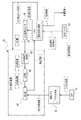
一例として図2に示すように、監視カメラ10は、光学系15及び撮像素子25を備えている。撮像素子25は、光学系15の後段に位置している。光学系15は、対物レンズ15A及びレンズ群15Bを備えている。対物レンズ15A及びレンズ群15Bは、監視対象側から撮像素子25の受光面25A側にかけて、光学系15の光軸OAに沿って、対物レンズ15A及びレンズ群15Bの順に配置されている。レンズ群15Bには、光軸OAに沿って移動可能なフォーカス用のレンズ及びズーム用のレンズ等が含まれており、フォーカス用のレンズ及びズーム用のレンズは、与えられた動力に応じて光軸OAに沿って移動する。このように構成された光学系15によって、監視対象を示す監視対象光は、受光面25Aに結像される。なお、撮像素子25は、本開示の技術に係る「撮像素子」の一例である。ここでは、撮像素子25として、CCDイメージセンサが採用されているが、これはあくまでも一例に過ぎず、撮像素子25は、CMOSイメージセンサ等の他のイメージセンサであってもよい。
As an example, as shown in FIG. 2, the
監視カメラ10は、ドライバ26、AFE30、DSP31、画像メモリ32、ぶれ補正装置33、通信I/F34、RAM35、ROM36、CPU37、ぶれ量検出センサ40、ディスプレイ42、及び受付デバイス43を備えている。ドライバ26、AFE30、DSP31、画像メモリ32、ぶれ補正装置33、通信I/F34、CPU37、ROM36、RAM35、ぶれ量検出センサ40、ディスプレイ42、及び受付デバイス43の各々は、バスライン38に接続されている。なお、ぶれ補正装置33は、本開示の技術に係る「ぶれ補正装置」の一例である。また、画像メモリ32は、本開示の技術に係る「メモリ」の一例である。
The
ROM36には、監視カメラ10用の各種プログラム(以下、単に「撮像装置用プログラム」と称する)が記憶されている。CPU37は、ROM36から撮像装置用プログラムを読み出し、読み出した撮像装置用プログラムをRAM35に展開する。CPU37は、RAM35に展開した撮像装置用プログラムに従って監視カメラ10の全体を制御する。
Various programs for the surveillance camera 10 (hereinafter, simply referred to as "programs for an image pickup device") are stored in the
撮像素子25には、ドライバ26及びAFE30の各々が接続されている。撮像素子25は、ドライバ26の制御の下、既定のフレームレートで監視対象を撮像する。ここで言う「既定のフレームレート」とは、例えば、数フレーム/秒から数十フレーム/秒を指す。
Each of the
受光面25Aは、マトリクス状に配置された複数の感光画素(図示省略)によって形成されている。撮像素子25では、各感光画素が露光され、感光画素毎に光電変換が行われる。感光画素毎に光電変換が行われることで得られた電荷は、監視対象を示すアナログの撮像信号であり、アナログ画像として撮像素子25に蓄積される。各感光画素は、アナログ画像が読み出される前後等のタイミングで、CPU37の制御の下、ドライバ26によってリセットされる。各感光画素に対する露光期間は、シャッタスピードに従って定められ、シャッタスピードは、各感光画素に対するリセットのタイミング及びアナログ画像の読み出しのタイミングが制御されることで調節される。
The
撮像素子25には、ドライバ26から垂直同期信号及び水平同期信号が入力される。垂直同期信号は、1フレーム分のアナログ画像の送信を開始するタイミングを規定する信号である。水平同期信号は、1水平ライン分のアナログ画像の出力を開始するタイミングを規定する信号である。撮像素子25は、ドライバ26から入力された垂直同期信号に従ってフレーム単位でのアナログ画像のAFE30への出力を開始し、ドライバ26から入力された水平同期信号に従って水平ライン単位でのアナログ画像のAFE30への出力を開始する。
A vertical synchronization signal and a horizontal synchronization signal are input to the
AFE30は、撮像素子25からのアナログ画像を受信する。換言すると、アナログ画像は、AFE30によって撮像素子25から読み出される。AFE30は、アナログ画像に対して、相関二重サンプリング及びゲイン調整等のアナログ信号処理を施した後、A/D変換を行うことで、デジタルの撮像信号であるデジタル画像を生成する。ここで、アナログ画像は、本開示の技術に係る「ぶれ補正装置」での撮像素子からの読出対象とされる「画像」の一例である。また、デジタル画像は、本開示の技術に係る「ぶれ補正装置」での補正部による補正対象とされる「画像」の一例である。なお、以下では、説明の便宜上、アナログ画像とデジタル画像とを区別して説明する必要がない場合、単に「画像」と称する。
The
なお、図2に示す例では、AFE30が撮像素子25の外部に設けられているが、本開示の技術はこれに限定されず、AFE30は、撮像素子25内に一体的に組み込まれていてもよい。
In the example shown in FIG. 2, the
DSP31は、デジタル画像に対して、各種デジタル信号処理を施す。各種デジタル信号処理とは、例えば、デモザイク処理、ノイズ除去処理、階調補正処理、及び色補正処理等を指す。DSP31は、1フレーム毎に、デジタル信号処理後のデジタル画像を画像メモリ32に出力する。画像メモリ32は、DSP31からのデジタル画像を記憶する。
The
ところで、監視カメラ10に与えられる振動には、屋外であれば、自動車の通行による振動、風による振動、及び道路工事による振動等があり、屋内であれば、エアコンディショナーの動作による振動、及び人の出入りによる振動等がある。そのため、監視カメラ10では、監視カメラ10に与えられた振動(以下、単に「振動」とも称する)に起因してぶれが生じる。本実施形態において、「ぶれ」とは、監視カメラ10において、デジタル画像が光軸OAと受光面25Aとの位置関係が変化することで変動する現象を指す。
By the way, the vibrations given to the
ぶれ量検出センサ40は、例えば、ジャイロセンサである。ジャイロセンサは、ピッチ軸PA、ヨー軸YA、及びロール軸RA(例えば、図2に示す光軸OAに平行な軸)の各軸(図1参照)周りの回転ぶれの量をぶれ量として検出する。なお、本実施形態での平行の意味には、完全な平行の意味の他に、設計上および製造上において許容される誤差を含む略平行の意味も含まれる。
The shake
なお、ここでは、ぶれ量検出センサ40の一例としてジャイロセンサを挙げているが、これはあくまでも一例であり、ぶれ量検出センサ40は、加速度センサであってもよい。加速度センサは、ピッチ軸PAとヨー軸YAに平行な2次元状の面内でのぶれ量を検出する。ぶれ量検出センサ40は、検出したぶれ量をCPU37に出力する。
Although the gyro sensor is mentioned here as an example of the shake
また、ここでは、ぶれ量検出センサ40という物理的なセンサによってぶれ量が検出される形態例を挙げているが、本開示の技術はこれに限定されない。例えば、画像メモリ32に記憶された時系列的に前後するデジタル画像を比較することで得た動きベクトルをぶれ量として用いてもよい。また、物理的なセンサによって検出されたぶれ量と、画像処理によって得られた動きベクトルとに基づいて最終的に使用されるぶれ量が導出されるようにてもよい。
Further, although an example in which the amount of blur is detected by a physical sensor called the blur
ぶれ補正装置33は、ASICを含むデバイス(本開示の技術に係る「プロセッサ」の一例)であり、ぶれ量検出センサ40によって検出されたぶれ量に応じたぶれ補正量を取得する。ぶれ補正量は、画像メモリ32に記憶されたデジタル画像のぶれの補正に供される。すなわち、ぶれ補正装置33は、取得したぶれ補正量に基づいて、画像メモリ32に記憶されたデジタル画像に対して画像処理を施すことでぶれを補正する。
The
本実施形態では、デジタル画像に対する画像処理の一例として、画像切出処理が採用されている。画像切出処理とは、画像メモリ32に記憶されたデジタル画像から一部の画像領域を切り出す処理を指す。画像切出処理が行われる場合、撮像素子25の撮像領域が、ぶれが補正されたデジタル画像として出力する領域(以下、単に「画像出力領域」)よりも広く設定された上で撮像が行われる。ぶれ補正量は、例えば、画像メモリ32に記憶されたデジタル画像のうちの画像出力領域以外の画像領域を特定する情報である。画像切出処理では、画像メモリ32に記憶されたデジタル画像から、ぶれ補正量に基づいて画像出力領域が特定される。そして、画像メモリ32に記憶されたデジタル画像から、特定された画像出力領域が切り出され、切り出された画像出力領域が、ぶれが補正されたデジタル画像として、CPU37を介して通信I/F34に出力される。
In this embodiment, image cutting processing is adopted as an example of image processing for a digital image. The image cutting process refers to a process of cutting out a part of an image area from a digital image stored in the
なお、本実施形態において、「ぶれの補正」には、ぶれを無くすという意味の他に、ぶれを低減するという意味も含まれる。ぶれ補正装置33は、ぶれを補正したデジタル画像を通信I/F34に出力する。
In the present embodiment, "correction of blurring" includes not only the meaning of eliminating blurring but also the meaning of reducing blurring. The
また、ここでは、ぶれ補正装置33として、ASICを含むデバイスを例示しているが、本開示の技術はこれに限定されるものではなく、例えば、FPGA又はPLDを含むデバイスであってもよい。また、例えば、ぶれ補正装置33は、ASIC、FPGA、及びPLDのうちの複数を含むデバイスであってもよい。また、ぶれ補正装置33として、CPU、ROM、及びRAMを含むコンピュータが採用されてもよい。CPUは、単数であってもよいし、複数であってもよい。また、ぶれ補正装置33は、ハードウェア構成及びソフトウェア構成の組み合わせによって実現されてもよい。
Further, although the device including the ASIC is exemplified here as the
通信I/F34は、例えば、ネットワークインターフェースであり、ネットワークを介して、管理装置11との間で各種情報の伝送制御を行う。ネットワークの一例としては、インターネット又は公衆通信網等のWANが挙げられる。監視カメラ10と管理装置11との間の通信を司る。通信I/F34は、ぶれ補正装置33からCPU37を介して入力されたデジタル画像、すなわち、ぶれ補正装置33によってぶれが補正されたデジタル画像を管理装置11に送信する。
The communication I /
受付デバイス43は、例えば、キーボード、マウス、及びタッチパネル等であり、ユーザからの各種指示を受け付ける。CPU37は、受付デバイス43によって受け付けられた各種指示を取得し、取得した指示に従って動作する。
The
ディスプレイ42は、CPU37の制御下で、各種情報を表示する。ディスプレイ42に表示される各種情報としては、例えば、受付デバイス43によって受け付けられた各種指示の内容、及びぶれ補正装置33によってぶれが補正されたデジタル画像等が挙げられる。
The
一例として図3に示すように、管理装置11は、ディスプレイ13、二次記憶装置14、コントローラ60、受付デバイス62、及び通信I/F66を備えている。コントローラ60は、CPU60A、ROM60B、及びRAM60Cを備えている。受付デバイス62、ディスプレイ13、二次記憶装置14、CPU60A、ROM60B、RAM60C、及び通信I/F66の各々は、バスライン70に接続されている。
As an example, as shown in FIG. 3, the
ROM60Bには、管理装置11用の各種プログラム(以下、単に「管理装置用プログラム」と称する)が記憶されている。CPU60Aは、ROM60Bから管理装置用プログラムを読み出し、読み出した管理装置用プログラムをRAM60Cに展開する。CPU60Aは、RAM60Cに展開した管理装置用プログラムに従って管理装置11の全体を制御する。
Various programs for the management device 11 (hereinafter, simply referred to as "management device program") are stored in the
通信I/F66は、例えば、ネットワークインターフェースである。通信I/F66は、ネットワークを介して、管理装置11の通信I/F34に対して通信可能に接続されており、管理装置11との間で各種情報の伝送制御を行う。例えば、通信I/F66は、管理装置11に対してデジタル画像の送信を要求し、デジタル画像の送信の要求に応じて管理装置11の通信I/F34から送信されたデジタル画像を受信する。
The communication I /
受付デバイス62は、例えば、キーボード、マウス、及びタッチパネル等であり、ユーザからの各種指示を受け付ける。CPU60Aは、受付デバイス62によって受け付けられた各種指示を取得し、取得した指示に従って動作する。
The
ディスプレイ13は、CPU60Aの制御下で、各種情報を表示する。ディスプレイ13に表示される各種情報としては、例えば、受付デバイス62によって受け付けられた各種指示の内容、及び通信I/F66によって受信されたデジタル画像等が挙げられる。
The
二次記憶装置14は、CPU60Aの制御下で、各種情報を記憶する。二次記憶装置14に記憶される各種情報としては、例えば、通信I/F66によって受信されたデジタル画像等が挙げられる。
The
このように、コントローラ60は、通信I/F66によって受信されたデジタル画像をディスプレイ13に対して表示させる制御、及び通信I/F66によって受信されたデジタル画像を二次記憶装置14に対して記憶させる制御を行う。
As described above, the
なお、ここでは、デジタル画像をディスプレイ13に対して表示させ、かつ、通信I/F66によって受信されたデジタル画像を二次記憶装置14に対して記憶させるようにしているが、本開示の技術はこれに限定されない。例えば、デジタル画像のディスプレイ13に対する表示とデジタル画像の二次記憶装置14に対する記憶との何れかが行われるようにしてもよい。
Here, the digital image is displayed on the
監視カメラ10により動画像用の撮像が行われる場合、一例として図4に示すように、CPU37は、フレーム単位で、垂直同期信号を、ドライバ26(図1参照)を介して撮像素子25に出力する。撮像素子25に垂直同期信号が入力されると、撮像素子25からアナログ画像の読み出しが開始される。そして、CPU37は、垂直同期信号が出力されてから既定時間(後述)が経過したときに、ぶれ量検出センサ40に対して、ぶれ量の検出を指示するぶれ量検出信号を出力する。ぶれ量検出センサ40は、CPU37からぶれ量検出信号が入力されると、ぶれ量を検出し、検出したぶれ量をぶれ補正装置33に出力する。
When imaging for a moving image is performed by the
詳しくは後述するが、ぶれ量検出センサ40によって検出されたぶれ量に応じて、ぶれ補正量が算出される。そして、ぶれ補正装置33は、ぶれ補正量取得タイミングで、ぶれ補正量を取得する。ここで言う「ぶれ補正量取得タイミング」とは、ぶれ補正装置33によってぶれ補正量が取得されるタイミングとして予め定められたタイミングを指す。図4に示す例では、ぶれ補正量取得タイミングとして、1フレーム分の露光期間の中央のタイミングが示されている。上記の既定時間とは、例えば、ぶれ補正装置33に対してぶれ補正量取得タイミングでぶれ補正量を取得させるタイミングにてCPU37に対して検出指示信号を出力させるまでに要する時間として予め定められた時間を指す。
As will be described in detail later, the blur correction amount is calculated according to the blur amount detected by the blur
一例として図5に示すように、ぶれ補正装置33は、ぶれ補正量算出部80、取得部82、補正部84、及び補正タイミング判定部88を備えている。なお、取得部82は、本開示の技術に係る「取得部」の一例であり、補正部84は、本開示の技術に係る「補正部」の一例である。
As an example, as shown in FIG. 5, the
ぶれ補正量算出部80は、ぶれ量検出センサ40によって検出されたぶれ量を取得し、取得したぶれ量に基づいてぶれ補正量を算出する。ぶれ補正量算出部80では、ぶれ量を独立変数とし、ぶれ補正量を従属変数とした演算式を用いてぶれ補正量が算出される。
The blur correction
なお、ここでは、ぶれ補正量が演算式を用いて算出される形態例を挙げているが、本開示の技術はこれに限定されない。例えば、ぶれ量とぶれ補正量とが対応付けられたぶれ補正量導出テーブル(図示省略)に基づいてぶれ補正量が導出されるようにしてもよい。 Although a form example in which the blur correction amount is calculated by using an arithmetic expression is given here, the technique of the present disclosure is not limited to this. For example, the blur correction amount may be derived based on the blur correction amount derivation table (not shown) in which the blur amount and the blur correction amount are associated with each other.
取得部82は、ぶれ補正量算出部80によって算出されたぶれ補正量を、上述のぶれ補正量取得タイミング(図4参照)で取得する。ぶれ補正量取得タイミングでぶれ補正量が取得されるということは、撮像素子25での1フレーム分の露光中にぶれ補正量が取得されるということを意味する。
The
補正タイミング判定部88は、画像メモリ32に補正対象画像が記憶されたか否かを判定し、画像メモリ32に補正対象画像が記憶された場合に、ぶれの補正を指示する補正指示信号を補正部84に出力する。補正対象画像とは、撮像素子25により撮像されることで得られた動画像に含まれる1フレーム分のデジタル画像を指す。つまり、ぶれ補正装置33では、DSP31によって画像メモリ32に記憶された1フレーム分のデジタル画像が補正対象画像として扱われる。また、画像メモリ32には、1フレーム毎にデジタル画像が記憶されるので、1フレーム毎のデジタル画像の各々が補正対象画像として扱われる。
The correction
補正タイミング判定部88は、画像メモリ32の記憶内容を監視しており、画像メモリ32に1フレーム分のデジタル画像が記憶された場合に、画像メモリ32に補正対象画像が記憶されたと判定し、補正指示信号を補正部84に出力する。
The correction
補正部84は、補正タイミング判定部88からの補正指示信号が入力されると、画像メモリ32から補正対象画像を取得し、取得した補正対象画像に対して、上述した画像切出処理を行うことで、ぶれを補正する。補正対象画像に対してぶれの補正が行われることで得られた補正画像は、補正部84によってCPU37に出力され、CPU37により通信I/F34を介して管理装置11に送信される。
When the correction instruction signal from the correction
ぶれ補正装置33は、上述した既定のフレームレートに従って撮像されることで得られた動画像に含まれる各デジタル画像に対して、同様の方法で、ぶれを補正する。そして、ぶれを補正することで得た各補正画像は、CPU37を介して管理装置11に順次に送信される。
The
管理装置11では、監視カメラ10のCPU37から送信された各補正画像がコントローラ60に順次に入力される。そして、ディスプレイ13は、コントローラ60の制御下で、コントローラ60に順次に入力された補正画像をライブビュー画像として表示し、二次記憶装置14は、コントローラ60の制御下で、コントローラ60に順次に入力された補正画像を記憶する。なお、コントローラ60は、本開示の技術に係る「コントローラ」の一例である。
In the
図6Aには、監視対象が撮像されることで得られた動画像に含まれる1フレーム目から3フレーム目までの各フレームについての露光期間及び読出期間の一例が示されている。ここで言う「露光期間」とは、撮像素子25に対して露光が行われている期間を指し、読出期間とは、撮像素子25からのアナログ画像の読み出しに要する期間を指す。
FIG. 6A shows an example of the exposure period and the reading period for each frame from the first frame to the third frame included in the moving image obtained by capturing the image of the monitored object. The "exposure period" referred to here refers to a period during which the
監視カメラ10では、ローリングシャッタ方式での撮像が行われる。従って、一例として図6Aに示すように、読出開始タイミングと読出終了タイミングとの間にずれが生じる。読出開始タイミングは、撮像素子25の撮像領域の1行目の水平ラインのアナログ画像の読み出しを行うタイミングであり、読出終了タイミングは、撮像素子25の撮像領域の最終行の水平ラインのアナログ画像の読み出しを行うタイミングである。ローリングシャッタ方式では、水平同期信号に従って撮像素子25の撮像領域の1行目から最終行にかけて1水平ライン毎に順次にアナログ画像の読み出しが行われる。そのため、読出終了タイミングは、読出開始タイミングよりも遅れて到来する。これに伴って、撮像素子25の撮像領域の1行目の露光が行われるタイミングと撮像素子25の撮像領域の最終行の露光が行われるタイミングとの間にずれが生じる。
In the
各フレームにおいて、ぶれ補正量は、撮像素子25の撮像領域の列方向の中央に位置する水平ラインに対する露光が行われているタイミングで取得部82(図5参照)によって取得される。より具体的には、撮像素子25の撮像領域の列方向の中央に位置する水平ラインの中央の感光画素に対する露光が行われるタイミングで取得部82によってぶれ補正量が取得される。なお、撮像素子25の撮像領域の列方向の中央に位置する水平ラインに対する露光が行われているタイミングは、本開示の技術に係る「補正対象画像に対応する露光が行われている期間のうちの特定のラインの露光が行われている間」の一例である。
In each frame, the blur correction amount is acquired by the acquisition unit 82 (see FIG. 5) at the timing when the horizontal line located at the center in the column direction of the image pickup region of the
ここでは、撮像素子25の撮像領域の列方向の中央に位置する水平ラインに対する露光が行われているタイミングで取得部82によってぶれ補正量が取得されているが、本開示の技術はこれに限定されない。例えば、撮像素子25の撮像領域の列方向の中央に位置する水平ラインよりも列方向に複数ライン分(例えば、数ラインから数十ライン分)だけ前又は後に位置する水平ラインに対する露光が行われているタイミングで取得部82によってぶれ補正量が取得されるようにしてもよい。
Here, the blur correction amount is acquired by the
図6Aに示す例では、1フレーム目について撮像素子25の撮像領域の列方向の中央に位置する水平ラインに対する露光が行われているタイミングで取得部82によってぶれ補正量Aが取得される。そして、撮像素子25から読み出された1フレーム目のアナログ画像に対応する1フレーム分のデジタル画像が補正対象画像として画像メモリ32に記憶されると、補正部84は、取得部82によって取得されたぶれ補正量Aに基づいて画像切出処理を行う。これにより、1フレーム目の補正対象画像に対するぶれが補正される。
In the example shown in FIG. 6A, the blur correction amount A is acquired by the
同様に、図6Bに示す例では、2フレーム目について撮像素子25の撮像領域の列方向の中央に位置する水平ラインに対する露光が行われているタイミングで取得部82によってぶれ補正量Bが取得される。そして、撮像素子25から読み出された2フレーム目のアナログ画像に対応する1フレーム分のデジタル画像が補正対象画像として画像メモリ32に記憶されると、補正部84は、取得部82によって取得されたぶれ補正量Bに基づいて画像切出処理を行う。これにより、2フレーム目の補正対象画像に対するぶれが補正される。
Similarly, in the example shown in FIG. 6B, the blur correction amount B is acquired by the
同様に、図6Cに示す例では、3フレーム目について撮像素子25の撮像領域の列方向の中央に位置する水平ラインに対する露光が行われているタイミングで取得部82によってぶれ補正量Cが取得される。そして、撮像素子25から読み出された3フレーム目のアナログ画像に対応する1フレーム分のデジタル画像が補正対象画像として画像メモリ32に記憶されると、補正部84は、取得部82によって取得されたぶれ補正量Cに基づいて画像切出処理を行う。これにより、3フレーム目の補正対象画像に対するぶれが補正される。なお、撮像されることで得られた動画像に含まれる3フレーム目以降の各フレームについても同様の処理が行われる。
Similarly, in the example shown in FIG. 6C, the blur correction amount C is acquired by the
次に、監視システム2の本開示の技術に係る部分の作用について説明する。 Next, the operation of the part of the monitoring system 2 according to the technique of the present disclosure will be described.
先ず、ぶれ補正装置33によって実行されるぶれ補正処理の流れについて図7を参照しながら説明する。
First, the flow of the blur correction process executed by the
図7に示すぶれ補正処理では、先ず、ステップST20で、ぶれ補正量算出部80は、ぶれ量検出センサ40によって検出されたぶれ量が入力されたか否かを判定する。ステップST20において、ぶれ量検出センサ40によって検出されたぶれ量が入力されていない場合は、判定が否定されて、ぶれ量補正処理はステップST34へ移行する。ステップST20において、ぶれ量検出センサ40によって検出されたぶれ量が入力された場合は、判定が肯定されて、ぶれ補正処理はステップST22へ移行する。
In the blur correction process shown in FIG. 7, first, in step ST20, the blur correction
ステップST22で、ぶれ補正量算出部80は、入力されたぶれ量に基づいてぶれ補正量を算出し、算出したぶれ補正量を取得部82に出力する。取得部82は、ぶれ補正量算出部80によって出力されたぶれ補正量を取得し、その後、ぶれ補正処理はステップST24へ移行する。
In step ST22, the blur correction
ステップST24で、補正タイミング判定部88は、画像メモリ32に補正対象画像が記憶されたか否かを判定する。すなわち、補正タイミング判定部88は、画像メモリ32に1フレーム分のデジタル画像が記憶されたか否かを判定する。ステップST24において、画像メモリ32に補正対象画像が記憶されていない場合は、判定が否定されて、ステップST24の判定が再び行われる。ここで、画像メモリ32に補正対象画像が記憶されていない場合とは、例えば、画像メモリ32にデジタル画像が何ら記憶されていない場合、及び画像メモリ32に記憶されているデジタル画像が1フレームに満たない場合を指す。ステップST24において、画像メモリ32に補正対象画像が記憶された場合は、判定が肯定されて、ぶれ補正処理はステップST26へ移行する。
In step ST24, the correction
ステップST26で、補正タイミング判定部88は、補正指示信号を補正部84に出力し、その後、ぶれ補正処理はステップST28へ移行する。
In step ST26, the correction
ステップST28で、補正部84は、補正タイミング判定部88からの補正指示信号が入力されたか否かを判定する。ステップST28において、補正タイミング判定部88からの補正指示信号が入力されていない場合は、判定が否定されて、ステップST28の判定が再び行われる。ステップST28において、補正タイミング判定部88からの補正指示信号が入力された場合は、判定が肯定されて、ぶれ補正処理はステップST30へ移行する。
In step ST28, the
ステップST30で、補正部84は、画像メモリ32に記憶されている補正対象画像を取得する。そして、補正部84は、取得した補正対象画像に対して、ステップST22で取得部82によって取得されたぶれ補正量に基づいて画像切出処理を実行することで、補正対象画像のぶれを補正し、その後、ぶれ補正処理はステップST32へ移行する。
In step ST30, the
ステップST32で、補正部84は、補正対象画像のぶれが補正されることで得られた補正画像をCPU37に出力し、その後、ぶれ補正処理はステップST34へ移行する。なお、CPU37は、補正部84から入力された補正画像を通信I/F34を介して管理装置11に送信する。
In step ST32, the
ステップST34で、補正部84は、ぶれ補正処理を終了する条件(以下、「ぶれ補正処理終了条件」と称する)を満足したか否かを判定する。ぶれ補正処理終了条件としては、例えば、ぶれ補正処理を終了させる指示が受付デバイス43によって受け付けられた、との条件が挙げられる。ステップST34において、ぶれ補正処理終了条件を満足していない場合は、判定が否定されて、ぶれ補正処理はステップST20へ移行する。ステップST34において、ぶれ補正処理終了条件を満足した場合は、判定が肯定されて、ぶれ補正処理が終了する。
In step ST34, the
次に、管理装置11のコントローラ60によって実行される管理処理の流れについて図8を参照しながら説明する。
Next, the flow of the management process executed by the
図8に示す管理処理では、先ず、ステップST40で、コントローラ60は、監視カメラ10から送信された補正画像が通信I/F66によって受信されたか否かを判定する。ステップST40において、監視カメラ10から送信された補正画像が通信I/F66によって受信されていない場合は、判定が否定されて、管理処理はステップST48へ移行する。ステップST40において、監視カメラ10から送信された補正画像が通信I/F66によって受信された場合は、判定が肯定されて、管理処理はステップST41へ移行する。
In the management process shown in FIG. 8, first, in step ST40, the
ステップST41で、コントローラ60は、補正画像がディスプレイ13に表示されているか否かを判定する。ステップST41において、補正画像がディスプレイ13に表示されていない場合、すなわち、補正画像がディスプレイ13に表示されていない場合は、判定が否定されて、管理処理はステップST42へ移行する。ステップST41において、補正画像がディスプレイ13に表示されている場合は、判定が肯定されて、管理処理はステップST44へ移行する。
In step ST41, the
ステップST42で、コントローラ60は、ディスプレイ13に対して、通信I/F66によって受信された最新の補正画像の表示を開始させ、その後、管理処理はステップST46へ移行する。
In step ST42, the
ステップST44で、コントローラ60は、ディスプレイ13に表示されている補正画像を、通信I/F66によって受信された最新の補正画像に更新し、その後、管理処理はステップST46に移行する。
In step ST44, the
ステップST46で、コントローラ60は、通信I/F66によって受信された最新の補正画像を二次記憶装置14に記憶し、その後、管理処理はステップST48へ移行する。
In step ST46, the
ステップST48で、コントローラ60は、管理処理を終了する条件(以下、「管理処理終了条件」と称する)を満足したか否かを判定する。管理処理終了条件としては、例えば、管理処理を終了させる指示が受付デバイス62によって受け付けられた、との条件が挙げられる。ステップST48において、管理処理終了条件を満足していない場合は、判定が否定されて、管理処理はステップST40へ移行する。ステップST48において、管理処理終了条件を満足した場合は、判定が肯定されて、管理処理はステップST50へ移行する。
In step ST48, the
ステップST50で、コントローラ60は、補正画像がディスプレイ13に表示されているか否かを判定する。ステップST50において、補正画像がディスプレイ13に表示されていない場合、すなわち、補正画像がディスプレイ13に表示されていない場合は、判定が否定されて、管理処理が終了する。ステップST50において、補正画像がディスプレイ13に表示されている場合は、判定が肯定されて、管理処理はステップST52へ移行する。
In step ST50, the
ステップST52で、コントローラ60は、ディスプレイ13に対して補正画像の表示を終了させ、その後、管理処理が終了する。
In step ST52, the
以上説明したように、監視カメラ10では、撮像されることで得られた動画像に含まれる補正対象画像に対して、補正対象画像を得るのに要する露光中に取得されたぶれ補正量に基づいて画像処理として画像切出処理が行われることでぶれが補正される。これにより、動画像に含まれる隣接する先フレーム及び後フレームのうち、後フレームのデジタル画像に対するぶれの補正は、先フレームの露光中に取得されたぶれ補正量の影響を受けない。従って、撮像されることで得られた動画像に含まれる隣接する2フレームの各画像に対して共通のぶれ補正量に基づいてぶれの補正が行われる場合に比べ、撮像されることで得られた動画像のぶれを高精度に補正することができる。
As described above, in the
また、監視カメラ10では、画像メモリ32に記憶された補正対象画像に対して、補正対象画像を得るのに要する露光中に取得されたぶれ補正量に基づいて画像処理として画像切出処理が行われることでぶれが補正される。つまり、画像メモリ32に記憶された1フレーム分のデジタル画像に対して、現時点で画像メモリ32に記憶されている1フレーム分のデジタル画像を得るのに要した露光中に取得されたぶれ補正量に基づいてぶれの補正が行われる。従って、ぶれ補正量の取得タイミングがアナログ画像の読出開始タイミングよりも遅い場合であっても、動画像に含まれる1フレーム内で取得されたぶれ補正量に基づいてぶれを補正することができる。
Further, in the
また、監視カメラ10では、デジタル画像が1フレーム毎に画像メモリ32に記憶され、画像メモリ32に記憶された1フレーム毎のデジタル画像の各々が補正対象画像として扱われる。従って、撮像されることで得られた動画像に含まれる隣接する2フレームの各画像に対して共通のぶれ補正量に基づいてぶれの補正が行われる場合に比べ、動画像に含まれる1フレーム毎の補正対象画像の各々のぶれを高精度に補正することができる。
Further, in the
更に、監視カメラ10では、補正対象画像に対応する露光が行われている期間のうちの中央の水平ラインの露光が行われている間にぶれ補正量が取得部82によって取得される。従って、補正対象画像に対応する露光が行われている期間のうちの中央の水平ラインの露光が行われている間に取得されたぶれ補正量に基づいて補正対象画像のぶれを補正することができる。
Further, in the
[第2実施形態]
上記第1実施形態では、ぶれ補正装置33による補正方法として、1種類の補正方法を例示したが、本第2実施形態では、2種類の補正方法を使い分ける形態例について説明する。なお、本第2実施形態では、上記第1実施形態と同一の構成要素については同一の符号を付し、その説明を省略する。以下では、上記第1実施形態と異なる部分について説明する。[Second Embodiment]
In the first embodiment, one type of correction method is exemplified as the correction method by the
一例として図9に示すように、ぶれ補正装置33に対しては、第1補正モード又は第2補正モードが設定され、監視カメラ10により撮像されることで得られた動画像のぶれが補正部84によって第1補正モード又は第2補正モードで補正される。
As an example, as shown in FIG. 9, the first correction mode or the second correction mode is set for the
一例として図9に示すように、ぶれ補正装置33に対しては、監視カメラ10により撮像されることで得られた動画像を管理装置11の二次記憶装置14(図3参照)に記憶させる場合に第1補正モードが設定される。また、ぶれ補正装置33に対しては、監視カメラ10により撮像されることで得られた動画像をライブビュー画像として管理装置11のディスプレイ13(図3参照)に対して表示させる場合に第2補正モードが設定される。
As an example, as shown in FIG. 9, for the
図10は、第1補正モードで画像のぶれが補正される場合のぶれ補正装置33の機能の一例を示す機能ブロック図であり、図11は、第2補正モードで画像のぶれが補正される場合のぶれ補正装置33の機能の一例を示す機能ブロック図である。
FIG. 10 is a functional block diagram showing an example of the function of the
一例として図10に示すように、管理装置11において、動画像記憶指示が受付デバイス62によって受け付けられると、受付デバイス62は、動画像記憶指示信号をコントローラ60に出力する。ここで、動画像記憶指示とは、監視カメラ10により撮像されることで得られた動画像を二次記憶装置14に記憶させる指示を指す。また、動画像記憶指示信号とは、監視カメラ10により撮像されることで得られた動画像を二次記憶装置14に記憶させる指示を示す信号を指す。
As an example, as shown in FIG. 10, when the moving image storage instruction is received by the receiving
コントローラ60は、動画像記憶指示信号を監視カメラ10に送信する。コントローラ60により送信された動画像記憶指示信号は、監視カメラ10の通信I/F34(図2参照)によって受信され、CPU37に動画像記憶指示信号が出力される。
The
CPU37は、動画像記憶指示信号が入力されると、第1補正モードで画像のぶれを補正することを指示する第1補正モード信号をぶれ補正装置33に出力する。ぶれ補正装置33は、第1補正モード信号が入力されると、第1補正モードで作動する。
When the moving image storage instruction signal is input, the
第1補正モードとは、上記第1実施形態で説明したぶれ補正処理(図7参照)が実行される補正モードである。すなわち、第1補正モードでは、補正部84が、補正対象画像を得るのに要する露光中に取得部82により取得されたぶれ補正量に基づいて補正対象画像に対して画像処理を施すことで補正対象画像のぶれを補正する。
The first correction mode is a correction mode in which the blur correction process (see FIG. 7) described in the first embodiment is executed. That is, in the first correction mode, the
一例として図11に示すように、管理装置11において、ライブビュー指示が受付デバイス62によって受け付けられると、受付デバイス62は、ライブビュー指示信号をコントローラ60に出力する。ここで、ライブビュー指示とは、監視カメラ10により撮像されることで得られた動画像をライブビュー画像としてディスプレイ13に対して表示させる指示を指す。また、ライブビュー指示信号とは、監視カメラ10により撮像されることで得られた動画像をライブビュー画像としてディスプレイ13に対して表示させる指示を示す信号を指す。
As an example, as shown in FIG. 11, when the live view instruction is received by the
コントローラ60は、ライブビュー指示信号を監視カメラ10に送信する。コントローラ60により送信されたライブビュー指示信号は、監視カメラ10の通信I/F34(図2参照)によって受信され、CPU37にライブビュー指示信号が出力される。
The
CPU37は、ライブビュー指示信号が入力されると、第2補正モードで画像のぶれを補正することを指示する第2補正モード信号をぶれ補正装置33に出力する。ぶれ補正装置33では、第2補正モード信号が入力されると、第2補正モードで作動する。
When the live view instruction signal is input, the
第2補正モードでは、補正部84は、画像メモリ32から、1フレームに満たないデジタル画像である未完画像を取得し、取得した未完画像のぶれを最新のぶれ補正量に基づいて補正する。すなわち、第2補正モードでは、補正部84は、画像メモリ32にデジタル画像が記憶されると、1フレーム分のデジタル画像が画像メモリ32に記憶される前に、画像メモリ32に既に記憶されたデジタル画像を未完画像として取得する。そして、補正部84は、未完画像に対して、取得部82によって取得された最新のぶれ補正量に基づいて画像切出処理を行うことで、未完画像のぶれを補正する。
In the second correction mode, the
次に、監視システム2の本開示の技術に係る部分の作用について説明する。 Next, the operation of the part of the monitoring system 2 according to the technique of the present disclosure will be described.
先ず、ぶれ補正装置33によって実行されるぶれ補正処理の流れについて図12を参照しながら説明する。
First, the flow of the blur correction process executed by the
図12に示すぶれ補正処理では、先ず、ステップST80で、ぶれ補正装置33は、CPU37から第1補正モード信号が入力されたか否かを判定する。ステップST80において、CPU37から第1補正モード信号が入力された場合、判定が肯定されて、ぶれ補正処理はステップST82へ移行する。ステップST80において、CPU73から第2補正モード信号が入力された場合、判定が否定されて、ぶれ補正処理はステップST84へ移行する。
In the blur correction process shown in FIG. 12, first, in step ST80, the
ステップST82で、ぶれ補正装置33は、第1補正モードぶれ補正処理を実行し、その後、ぶれ補正処理はステップST86へ移行する。ここで、第1補正モードぶれ補正処理とは、上記第1実施形態で説明したぶれ補正処理(図7参照)を指す。
In step ST82, the
ステップST84で、ぶれ補正装置33は、後述の第2補正モードぶれ補正処理(図13参照)を実行し、その後、ぶれ補正処理はステップST86へ移行する。
In step ST84, the
ステップST86で、ぶれ補正装置33は、上記第1実施形態で説明したぶれ補正処理終了条件を満足したか否かを判定する。ステップST86において、ぶれ補正処理終了条件を満足していない場合は、判定が否定されて、ぶれ補正処理はステップST80へ移行する。ステップST86において、ぶれ補正処理終了条件を満足した場合は、判定が肯定されて、ぶれ補正処理が終了する。
In step ST86, the
次に、監視システム2の本開示の技術に係る部分の作用について説明する。なお、本第2実施形態では、上記第1実施形態で説明した作用とは異なる部分について説明する。 Next, the operation of the part of the monitoring system 2 according to the technique of the present disclosure will be described. In the second embodiment, a part different from the operation described in the first embodiment will be described.
先ず、ぶれ補正装置33によって実行される第2補正モードぶれ補正処理の流れについて図13を参照しながら説明する。
First, the flow of the second correction mode blur correction process executed by the
図13に示す第2補正モードぶれ補正処理では、先ず、ステップST100で、ぶれ補正量算出部80は、ぶれ量検出センサ40によって検出されたぶれ量が入力されたか否かを判定する。ステップST100において、ぶれ量検出センサ40によって検出されたぶれ量が入力されていない場合は、判定が否定されて、第2補正モードぶれ量補正処理はステップST112へ移行する。ステップST100において、ぶれ量検出センサ40によって検出されたぶれ量が入力された場合は、判定が肯定されて、第2補正モードぶれ補正処理はステップST102へ移行する。
In the second correction mode blur correction process shown in FIG. 13, first, in step ST100, the blur correction
ステップST102で、ぶれ補正量算出部80は、入力されたぶれ量に基づいてぶれ補正量を算出し、算出したぶれ補正量を取得部82に出力する。取得部82は、ぶれ補正量算出部80によって出力されたぶれ補正量を取得し、その後、ぶれ補正処理はステップST104へ移行する。
In step ST102, the blur correction
ステップST104で、補正部84は、画像メモリ32に未完画像が記憶されているか否かを判定する。ここで、画像メモリ32に未完画像が記憶されていない場合とは、画像メモリ32にデジタル画像が何ら記憶されていない場合を指す。また、画像メモリ32に未完画像が記憶されている場合とは、画像メモリ32に1フレーム未満のデジタル画像が記憶されている場合を指す。
In step ST104, the
ステップST104において、画像メモリ32に未完画像が記憶されていない場合は、判定が否定されて、ステップST104の判定が再び行われる。ステップST104において、画像メモリ32に未完画像が記憶されている場合は、第2補正モードぶれ補正処理はステップST106へ移行する。
If the unfinished image is not stored in the
ステップST106で、補正部84は、画像メモリ32に記憶されている未完画像を取得し、その後、第2補正モードぶれ補正処理はステップST108へ移行する。
In step ST106, the
ステップST108で、補正部84は、取得した未完画像に対して、ステップST102で取得部82によって取得されたぶれ補正量に基づいて画像切出処理を実行することで、未完画像のぶれを補正し、その後、第2補正モードぶれ補正処理はステップST110へ移行する。
In step ST108, the
ステップST110で、補正部84は、未完画像のぶれが補正されることで得られた補正画像をCPU37に出力し、その後、第2補正モードぶれ補正処理はステップST110へ移行する。なお、CPU37は、補正部84から入力された補正画像を通信I/F34を介して管理装置11に送信する。
In step ST110, the
ステップST112で、補正部84は、第2補正モードぶれ補正処理を終了する条件(以下、「第2補正モードぶれ補正処理終了条件」と称する)を満足したか否かを判定する。第2補正モードぶれ補正処理終了条件としては、例えば、第2補正モードぶれ補正処理を終了させる指示が受付デバイス43によって受け付けられた、との条件が挙げられる。ステップST112において、第2補正モードぶれ補正処理終了条件を満足していない場合は、判定が否定されて、第2補正モードぶれ補正処理はステップST100へ移行する。ステップST112において、第2補正モードぶれ補正処理終了条件を満足した場合は、判定が肯定されて、第2補正モードぶれ補正処理が終了する。
In step ST112, the
以上説明したように、本第2実施形態に係る監視カメラ10では、補正部84によって第1補正モード又は第2補正モードによって画像のぶれが補正される。第1補正モードでは、上記第1実施形態で説明したぶれ補正処理が実行され、第2補正モードでは、未完画像のぶれが最新のぶれ補正量に基づいて補正される。つまり、第1補正モードでは、補正対象画像を得るのに要する露光中に取得されたぶれ補正量に基づいて補正対象画像のぶれが補正され、第2補正モードでは、1フレーム未満のデジタル画像である未完画像に対して最新のぶれ補正量に基づいてぶれが補正される。従って、第1補正モードでは、第2補正モードよりもぶれの補正の高精度化を実現することができ、第2補正モードでは、第1補正モードよりもぶれの補正の高速化を実現することができる。
As described above, in the
また、本第2実施形態に係る監視カメラ10では、撮像されることで得られた動画像を二次記憶装置14に記憶させる場合に第1補正モードで補正対象画像のぶれが補正される。従って、第2補正モードで未完画像のぶれを補正する場合に比べ、ぶれの補正の精度が高い動画像を保存することができる。
Further, in the
また、本第2実施形態に係る監視カメラ10では、撮像されることで得られた動画像をライブビュー画像としてディスプレイ13に対して表示させる場合に第2補正モードで未完画像のぶれが補正される。第1補正モードでは、1フレーム分のデジタル画像である補正対象画像が画像メモリ32に記憶されるのを待つ必要があるのに対し、第2補正モードでは、補正対象画像が画像メモリ32に記憶されるのを待つ必要がない。つまり、第2補正モードでは、画像メモリ32に1フレーム分のデジタル画像が記憶される前の段階で、1フレームに満たないデジタル画像である未完画像を対象にしてぶれの補正が行われる。従って、補正対象画像が画像メモリ32に記憶されるのを待ってから補正対象画像のぶれを補正して得た補正画像をディスプレイ13に表示させる場合に比べ、リアルタイム性の高い動画像をディスプレイ13に表示させることができる。
Further, in the
なお、上記第2実施形態では、動画像を二次記憶装置14に記憶させる場合に第1補正モードが設定され、動画像をディスプレイ13に対して表示させる場合に第2補正モードが設定される場合について説明したが、本開示の技術はこれに限定されない。監視カメラ10と管理装置11との間で情報の授受を行う場合、情報を送信してから受信するまでの間、タイムラグが発生する。タイムラグが発生するのであれば、第2補正モードよりもぶれの補正に時間を要する第1補正モードでぶれの補正を行う時間を確保することができる。そこで、一例として図14に示すように、監視カメラ10から管理装置11に動画像が送信される場合にぶれ補正装置33に対して第1補正モードが設定される。また、監視カメラ10から管理装置11に動画像が送信されない場合にぶれ補正装置33に対して第2補正モードが設定される。
In the second embodiment, the first correction mode is set when the moving image is stored in the
この場合、ぶれ補正装置33はデフォルトの状態では第2補正モードで作動し、一例として図15に示すように、ぶれ補正装置33にCPU37から第1補正モード信号が入力されると、第2補正モードから第1補正モードに移行する。
In this case, the
一例として図15に示すように、管理装置11において、送信要求指示が受付デバイス62によって受け付けられると、受付デバイス62は、補正画像送信要求信号をコントローラ60に出力する。ここで、送信要求指示とは、監視カメラ10に対して補正画像の送信を要求する指示を指す。また、補正画像送信要求信号とは、監視カメラ10に対して補正画像の送信を要求する指示を示す信号を指す。
As an example, as shown in FIG. 15, when the transmission request instruction is received by the
コントローラ60は、補正画像送信要求指示信号を監視カメラ10に送信する。コントローラ60により送信された補正画像送信指示信号は、監視カメラ10の通信I/F34(図2参照)によって受信され、CPU37に補正画像送信指示信号が出力される。
The
CPU37は、補正画像送信要求指示信号が入力されると、第1補正モード信号をぶれ補正装置33に出力する。ぶれ補正装置33は、第1補正モード信号が入力されると、第1補正モードで作動する。
When the correction image transmission request instruction signal is input, the
このように、監視カメラ10から動画像を管理装置11に送信する場合に、補正部84によって第1補正モードでぶれの補正が行われる。この場合、監視カメラ10から管理装置11への動画像の送信に要するタイムラグを利用して第2補正モードよりもぶれの補正に時間を要する第1補正モードでぶれの補正を行う時間を確保することができる。従って、第2補正モードで未完画像のぶれを補正する場合に比べ、ぶれの補正の精度が高い動画像を監視カメラ10から管理装置11に送信することができる。
In this way, when the moving image is transmitted from the
[第3実施形態]
上記第2実施形態では、露光期間の長短とは無関係に第1補正モード又は第2補正モードが設定される場合について説明したが、本第3実施形態では、露光期間の長短に応じて第1補正モードと第2補正モードとが選択的に設定される場合について説明する。なお、本第3実施形態では、上記第1及び第2実施形態と同一の構成要素については同一の符号を付し、その説明を省略する。以下では、上記第1及び第2実施形態と異なる部分について説明する。[Third Embodiment]
In the second embodiment, the case where the first correction mode or the second correction mode is set regardless of the length of the exposure period has been described, but in the third embodiment, the first correction mode is set according to the length of the exposure period. A case where the correction mode and the second correction mode are selectively set will be described. In the third embodiment, the same components as those in the first and second embodiments are designated by the same reference numerals, and the description thereof will be omitted. Hereinafter, the parts different from the first and second embodiments will be described.
本第3実施形態に係るぶれ補正装置33に含まれる補正部84は、第1補正モード及び第2補正モードのうち、上記第1実施形態で説明した読出開始タイミング及び取得部82によるぶれ補正量の取得タイミングに応じて定められた補正モードでぶれの補正を行う。具体的には、一例として図16に示すように、撮像素子25による1フレーム分の撮像において、取得部82によるぶれ補正量の取得タイミングが読出開始タイミング以前であれば、補正部84は、第1補正モードでぶれを補正する。また、撮像素子25による1フレーム分の撮像において、取得部82によるぶれ補正量の取得タイミングが読出開始タイミングよりも遅ければ第2補正モードでぶれを補正する。
The
図17には、図6Aに示す例よりも各フレームの露光期間を長くした場合の1フレーム目及び2フレーム目の各々の露光期間及び読出期間の一例が示されている。図17に示す例では、図6Aに示す例の撮像が行われる場合の各フレームのシャッタスピードよりも、各フレームのシャッタスピードが遅く設定されることによって図6Aに示す例よりも露光期間が長く設定されている。 FIG. 17 shows an example of the exposure period and the reading period of each of the first frame and the second frame when the exposure period of each frame is longer than the example shown in FIG. 6A. In the example shown in FIG. 17, the exposure period is longer than the example shown in FIG. 6A because the shutter speed of each frame is set to be slower than the shutter speed of each frame when the example shown in FIG. 6A is imaged. It is set.
図17に示す例では、動画像に含まれる1フレーム目において、取得部82によるぶれ補正量Aの取得タイミングが読出開始タイミングよりも早い。すなわち、取得部82は、1フレーム目の露光中において、ぶれ補正量Aを、読出開始タイミングよりも早く取得している。この場合、1フレーム目の補正対象画像に対しては、ぶれ補正量Aに基づいて画像切出処理が行われることで、ぶれの補正が行われる。なお、図17に示す例において、1フレーム目の読出開始タイミングは、本開示の技術に係る「撮像素子からの画像の読み出しの開始時点」の一例である。
In the example shown in FIG. 17, in the first frame included in the moving image, the acquisition timing of the blur correction amount A by the
図17に示す例では、動画像用の撮像において、隣接する1フレーム目及び2フレーム目のうちの1フレーム目の撮像には第1読出期間が設定されており、2フレーム目の撮像には第2読出期間が設定されている。第1読出期間は、1フレーム目のアナログ画像が撮像素子25から読み出される期間である。第2読出期間は、2フレーム目のアナログ画像が撮像素子25から読み出される期間である。
In the example shown in FIG. 17, in the imaging for a moving image, the first readout period is set for the imaging of the first frame of the adjacent first frame and the second frame, and the imaging of the second frame is performed. The second read period is set. The first reading period is a period during which the analog image of the first frame is read from the
図17に示す例では、第1読出期間と第2読出期間とが重複していない。そして、第1読出期間と第2読出期間との間の露光中に取得部82によってぶれ補正量Bが取得される。この場合、2フレーム目の補正対象画像に対しては、取得部82によって取得されたぶれ補正量Bに基づいて画像切出処理が行われることで、ぶれの補正が行われる。なお、ここで言う「1フレーム目」は、本開示の技術に係る「先フレーム」の一例であり、ここで言う「2フレーム目」は、本開示の技術に係る「後フレーム」の一例である。また、ここでは、1フレーム目と2フレーム目との関係性を例示しているが、これは、あくまでも一例であり、本開示の技術はこれに限定されない。すなわち、撮像されることで得られた動画像に含まれる2フレーム目以降の隣接する先フレーム及び後フレームも、図17に示す例の1フレーム目及び2フレーム目と同様の関係性を有する。
In the example shown in FIG. 17, the first read period and the second read period do not overlap. Then, the blur correction amount B is acquired by the
図18には、第1補正モードで画像のぶれが補正される場合のぶれ補正装置33の機能の一例が示されており、図19には、第2補正モードで画像のぶれが補正される場合のぶれ補正装置33の機能の一例が示されている。
FIG. 18 shows an example of the function of the
図18に示すぶれ補正装置33は、図10に示すぶれ補正装置33に比べ、補正タイミング判定部88を有しない点が異なる。第1補正モードにおいて、補正部84は、補正指示信号の入力がなくとも画像メモリ32からデジタル画像を取得する。具体的には、第1補正モードにおいて、補正部84は、取得部82によってぶれ補正量が取得されたことをトリガーとして、既に画像メモリ32に記憶されているデジタル画像を取得し、取得したデジタル画像に対してぶれ補正量に基づくぶれの補正を行う。
The
すなわち、補正部84は、画像メモリ32内のデジタル画像が未完画像であったとしても、取得部82によってぶれ補正量が取得されたことをトリガーとして、画像メモリ32からデジタル画像を取得し、取得したデジタル画像に対してぶれの補正を行う。現在のフレームでぶれの補正対象とされた1フレーム分のデジタル画像に対するぶれの補正は、次のフレームの露光中に取得部82によってぶれ補正量が取得されるまでに完了する。
That is, even if the digital image in the
一例として図18に示すように、露光期間指示が受付デバイス43によって受け付けられると、受付デバイス43は、露光期間指示信号をコントローラ60に出力する。ここで、露光期間指示とは、1フレーム分の露光期間の指示を指す。また、露光期間指示信号とは、1フレーム分の露光期間の指示を示す信号を指す。
As an example, as shown in FIG. 18, when the exposure period instruction is received by the
コントローラ60は、露光期間指示信号を監視カメラ10に送信する。コントローラ60により送信された露光期間指示信号は、監視カメラ10の通信I/F34(図2参照)によって受信され、CPU37に露光期間指示信号が出力される。
The
CPU37は、露光期間指示信号が入力されると、露光期間指示信号により指示された露光期間が閾値以上か否かを判定する。閾値は、実機による試験及び/又はコンピュータ・シミュレーション等によって、既定の条件を満足する露光期間として予め定められた値である。既定の条件とは、各フレームにおいて、取得部82によるぶれ補正量の取得タイミングが読出開始タイミングよりも早く、かつ、先フレーム読出期間と後フレーム読出期間とが重複しない、との条件を指す。ここで、先フレーム読出期間とは、隣接する先フレーム及び後フレームのうちの先フレームのアナログ画像の読出期間を指す。後フレーム読出期間とは、隣接する先フレーム及び後フレームのうちの後フレームのアナログ画像の読出期間を指す。
When the exposure period instruction signal is input, the
CPU37は、露光期間指示信号により指示された露光期間が閾値以上の場合に第1補正モード信号をぶれ補正装置33に出力する。ぶれ補正装置33は、CPU37から第1補正モード信号が入力されると、第1補正モードで作動する。本第3実施形態において、ぶれ補正装置33に対して第1補正モードが設定されると、補正部84は、既に画像メモリ32に記憶されているデジタル画像を取得し、取得したデジタル画像に対して、現時点で取得部82によって取得されているぶれ補正量に基づいてぶれを補正する。同じぶれ補正量に基づくぶれの補正は、1フレーム分のデジタル画像に対して行われる。結果的に、これは、上記第1及び第2実施形態で説明した補正対象画像に対してぶれの補正が行われることと技術的に同じ意義を有する。
The
一例として図19に示すように、CPU37は、露光期間指示信号により指示された露光期間が閾値未満の場合に第2補正モード信号をぶれ補正装置33に出力する。ぶれ補正装置33は、CPU37から第2補正モード信号が入力されると、上記第2実施形態で説明した第2補正モードで作動する。
As an example, as shown in FIG. 19, the
次に、監視システム2の本開示の技術に係る部分の作用について説明する。なお、本第3実施形態では、上記第2実施形態で説明した作用とは異なる部分について説明する。 Next, the operation of the part of the monitoring system 2 according to the technique of the present disclosure will be described. In the third embodiment, a part different from the operation described in the second embodiment will be described.
図20には、ぶれ補正装置33によって実行される第1補正モードぶれ補正処理の流れの一例が示されている。
FIG. 20 shows an example of the flow of the first correction mode blur correction process executed by the
図20に示す第1補正モードぶれ補正処理では、先ず、ステップST150で、ぶれ補正量算出部80は、ぶれ量検出センサ40によって検出されたぶれ量が入力されたか否かを判定する。ステップST150において、ぶれ量検出センサ40によって検出されたぶれ量が入力されていない場合は、判定が否定されて、第1補正モードぶれ量補正処理はステップST164へ移行する。ステップST150において、ぶれ量検出センサ40によって検出されたぶれ量が入力された場合は、判定が肯定されて、第1補正モードぶれ補正処理はステップST152へ移行する。
In the first correction mode blur correction process shown in FIG. 20, first, in step ST150, the blur correction
ステップST152で、ぶれ補正量算出部80は、入力されたぶれ量に基づいてぶれ補正量を算出し、算出したぶれ補正量を取得部82に出力する。取得部82は、ぶれ補正量算出部80によって出力されたぶれ補正量を取得し、その後、第1補正モードぶれ補正処理はステップST154へ移行する。
In step ST152, the blur correction
ステップST154で、補正部84は、画像メモリ32にデジタル画像が記憶されたか否かを判定する。ステップST154において、画像メモリ32にデジタル画像が記憶されていない場合は、判定が否定されて、ステップST154の判定が再び行われる。ここで、画像メモリ32にデジタル画像が記憶されていない場合とは、例えば、画像メモリ32にデジタル画像が何ら記憶されていない場合を指す。ステップST154において、画像メモリ32にデジタル画像が記憶された場合は、判定が肯定されて、第1補正モードぶれ補正処理はステップST156へ移行する。
In step ST154, the
ステップST156で、補正部84は、画像メモリ32に記憶されているデジタル画像を取得し、その後、第1補正モードぶれ補正処理はステップST158へ移行する。
In step ST156, the
ステップST158で、補正部84は、ステップST156で取得したデジタル画像に対して、ステップST152で取得部82によって取得されたぶれ補正量に基づいて画像切出処理を実行することで、デジタル画像のぶれを補正し、その後、第1補正モードぶれ補正処理はステップST160へ移行する。
In step ST158, the
ステップST160で、補正部84は、デジタル画像のぶれが補正されることで得られた補正画像をCPU37に出力し、その後、第1補正モードぶれ補正処理はステップST162へ移行する。なお、CPU37は、補正部84から入力された補正画像を通信I/F34を介して管理装置11に送信する。
In step ST160, the
ステップST162で、補正部84は、1フレーム分のデジタル画像に対してステップST158の処理が完了したか否かを判定する。ステップST162において、1フレーム分のデジタル画像に対してステップST158の処理が完了していない場合は、判定が否定されて、第1補正モードぶれ補正処理はステップST154へ移行する。ステップST162において、1フレーム分のデジタル画像に対してステップST158の処理が完了した場合は、判定が肯定されて、第1補正モードぶれ補正処理はステップST164へ移行する。
In step ST162, the
ステップST164で、補正部84は、第1補正モードぶれ補正処理を終了する条件(以下、「第1補正モードぶれ補正処理終了条件」と称する)を満足したか否かを判定する。第1補正モードぶれ補正処理終了条件としては、例えば、第1補正モードぶれ補正処理を終了させる指示が受付デバイス43によって受け付けられた、との条件が挙げられる。ステップST164において、第1補正モードぶれ補正処理終了条件を満足していない場合は、判定が否定されて、第1補正モードぶれ補正処理はステップST150へ移行する。ステップST152において、第1補正モードぶれ補正処理終了条件を満足した場合は、判定が肯定されて、第1補正モードぶれ補正処理が終了する。
In step ST164, the
以上説明したように、本第3実施形態に係る監視カメラ10では、1フレーム目の露光中において撮像素子25からのアナログ画像の読み出しの開始時点よりも早くぶれ補正量が取得部82によって取得される。従って、1フレーム目に読み出された1フレーム分のアナログ画像に対応する1フレーム分のデジタル画像である補正対象画像に対して、1フレーム目の露光期間に取得されたぶれ補正量に基づいてぶれの補正を行うことができる。
As described above, in the
また、本第3実施形態に係る監視カメラ10では、第1読出期間と第2読出期間とが重複しない場合において、2フレーム目の1フレーム分のデジタル画像に対して、第1読出期間と第2読出期間との間の露光中に取得されたぶれ補正量に基づいてぶれが補正される。これにより、2フレーム目の1フレーム分のデジタル画像のぶれは、1フレーム目に取得されたぶれ補正量の影響を受けることなく、2フレーム目の露光中に取得されたぶれ補正量に基づいて補正される。3フレーム目以降のデジタル画像に対するぶれについても同様の方法で補正される。従って、隣接する先フレーム及び後フレームのうちの後フレームのデジタル画像に対するぶれの補正に対して、先フレームの露光中に取得されたぶれ補正量が影響を及ぼすことを回避することができる。
Further, in the
また、本第3実施形態に係る監視カメラ10では、第1補正モード及び第2補正モードのうち、読出開始タイミングと取得部82によるぶれ補正量の取得タイミングとに応じて定められた補正モードでぶれが補正される。従って、第1補正モード及び第2補正モードのうち、読出開始タイミング及び取得部82によるぶれ補正量の取得タイミングとは無関係に決められた補正モードでぶれが補正される場合に比べ、適切な補正モードでぶれを補正することができる。
Further, in the
更に、本第3実施形態に係る監視カメラ10では、取得部82によるぶれ補正量の取得タイミングが読出開始タイミング以前であれば第1補正モードでぶれが補正される。また、取得部82によるぶれ補正量の取得タイミングが読出開始タイミングよりも遅ければ第2補正モードでぶれが補正される。従って、第1補正モード及び第2補正モードのうち、取得部82によるぶれ補正量の取得タイミングと読出開始タイミングとの関係性に依らずに決められた補正モードでぶれが補正される場合に比べ、適切な補正モードでぶれを補正することができる。
Further, in the
なお、上記第3実施形態では、第1読出期間と第2読出期間との間の露光期間の中央の時点に取得されたぶれ補正量Bに基づいて2フレーム目のデジタル画像のぶれが補正される形態例を挙げて説明したが、本開示の技術はこれに限定されない。例えば、図21に示すように、第1読出期間と第2読出期間との間の1フレーム分の全露光期間を通じて取得部82によって取得された複数のぶれ補正量Bに基づいて2フレーム目のデジタル画像に対して画像切出処理を施すことでぶれを補正するようにしてもよい。複数のぶれ補正量Bを利用する形態例としては、複数のぶれ補正量B(図21に示す例では、5つのぶれ補正量B)の平均値に基づいて2フレーム目のデジタル画像に対して画像切出処理を施すことでぶれが補正される形態例が挙げられる。3フレーム目以降のデジタル画像に対しても同様の方法でぶれを補正することが可能である。このようにぶれを補正することで、1つのぶれ補正量のみに基づいてぶれが補正される場合に比べ、ぶれの補正精度を高めることができる。
In the third embodiment, blurring of the digital image in the second frame is corrected based on the blurring correction amount B acquired at the center of the exposure period between the first reading period and the second reading period. However, the technique of the present disclosure is not limited to this. For example, as shown in FIG. 21, the second frame is based on the plurality of blur correction amounts B acquired by the
また、上記第3実施形態では、シャッタスピードが調節されることで第1読出期間と第2読出期間とが重複しない露光期間が設定される形態例に挙げて説明したが、本開示の技術はこれに限定されない。例えば、CPU37は、シャッタスピードの調節に加え、撮像素子25の撮像領域の各感光画素に対するリセットのタイミングと、撮像素子25に対する垂直同期信号の入力タイミングとを制御することで、上述した既定の条件を満足する露光期間を設定してもよい。このように制御することで、例えば、隣接する先フレーム及び後フレームのうちの先フレームの読出期間が後フレームの露光期間と重ならないようにすることもできる。これにより、図21に示す例に比べ、先フレームの読出期間の終了時点と後フレームの露光期間中でのぶれ補正量の取得タイミングとが離れるので、図21に示す例に比べ、先フレーム(例えば1フレーム目)のぶれの補正を、余裕をもって行うことができる。また、図21に示す例に比べ、後フレーム(例えば2フレーム目)のぶれの補正も、余裕をもって行うことができる。
Further, in the third embodiment, the technique of the present disclosure has been described as an example in which an exposure period in which the first read period and the second read period do not overlap is set by adjusting the shutter speed. Not limited to this. For example, in addition to adjusting the shutter speed, the
また、上記各実施形態では、ぶれ補正装置33としてASICを含むデバイスを例示しているが、本開示の技術はこれに限定されない。例えば、ぶれ補正装置33は、コンピュータによるソフトウェア構成により実現されるようにしてもよい。
Further, in each of the above embodiments, a device including an ASIC is exemplified as the
この場合、例えば、図22に示すように、ぶれ補正装置33は、コンピュータ1852を備えている。そして、コンピュータ1852に上述したぶれ補正処理を実行させるためのぶれ補正プログラム1902を記憶媒体1900に記憶させておく。コンピュータ1852は、CPU1852A、ROM1852B、及びRAM1852Cを備えている。記憶媒体1900に記憶されているぶれ補正プログラム1902は、コンピュータ1852にインストールされ、CPU1852Aは、ぶれ補正プログラム1902に従って、上述したぶれ補正処理を実行する。
In this case, for example, as shown in FIG. 22, the
図22に示す例では、CPU1852Aは、単数のCPUであるが、本開示の技術はこれに限定されず、複数のCPUを採用してもよい。なお、記憶媒体1900の一例としては、SSD又はUSBメモリなどの任意の可搬型の記憶媒体が挙げられる。
In the example shown in FIG. 22, the
また、通信網(図示省略)を介してコンピュータ1852に接続される他のコンピュータ又はサーバ装置等の記憶部にぶれ補正プログラム1902を記憶させておき、上述の監視カメラ10の要求に応じてぶれ補正プログラム1902がコンピュータ1852にダウンロードされるようにしてもよい。この場合、ダウンロードされたぶれ補正プログラム1902がコンピュータ1852のCPU1852Aによって実行される。
Further, the
また、コンピュータ1852は、ぶれ補正装置33の外部に設けられるようにしてもよい。この場合、コンピュータ1852がぶれ補正プログラム1902に従ってぶれ補正装置33を制御するようにすればよい。
Further, the
上記のぶれ補正処理を実行するハードウェア資源としては、次に示す各種のプロセッサを用いることができる。プロセッサとしては、例えば、上述したように、ソフトウェア、すなわち、プログラムを実行することで、ぶれ補正処理を実行するハードウェア資源として機能する汎用的なプロセッサであるCPUが挙げられる。また、プロセッサとしては、例えば、FPGA、PLD、又はASICなどの特定の処理を実行させるために専用に設計された回路構成を有するプロセッサである専用電気回路が挙げられる。何れのプロセッサにもメモリが内蔵又は接続されており、何れのプロセッサもメモリを使用することでぶれ補正処理を実行する。 As the hardware resource for executing the above-mentioned blur correction process, various processors shown below can be used. Examples of the processor include, as described above, software, that is, a CPU, which is a general-purpose processor that functions as a hardware resource for executing blur correction processing by executing a program. In addition, examples of the processor include a dedicated electric circuit, which is a processor having a circuit configuration specially designed for executing a specific process such as FPGA, PLD, or ASIC. A memory is built-in or connected to any processor, and each processor executes blur correction processing by using the memory.
ぶれ補正処理を実行するハードウェア資源は、これらの各種のプロセッサのうちの1つで構成されてもよいし、同種または異種の2つ以上のプロセッサの組み合わせ(例えば、複数のFPGAの組み合わせ、又はCPUとFPGAとの組み合わせ)で構成されてもよい。また、ぶれ補正処理を実行するハードウェア資源は1つのプロセッサであってもよい。 The hardware resource that performs the blur correction process may consist of one of these various processors, or a combination of two or more processors of the same type or dissimilarity (eg, a combination of multiple FPGAs, or a combination of multiple FPGAs). It may be composed of a combination of a CPU and an FPGA). Further, the hardware resource for executing the blur correction process may be one processor.
1つのプロセッサで構成する例としては、第1に、クライアント及びサーバなどのコンピュータに代表されるように、1つ以上のCPUとソフトウェアの組み合わせで1つのプロセッサを構成し、このプロセッサが、ぶれ補正装置33内の処理を実行するハードウェア資源として機能する形態がある。第2に、SoCなどに代表されるように、ぶれ補正処理を実行する複数のハードウェア資源を含むシステム全体の機能を1つのICチップで実現するプロセッサを使用する形態がある。このように、ぶれ補正装置33内の処理は、ハードウェア資源として、上記各種のプロセッサの1つ以上を用いて実現される。
As an example of configuring with one processor, first, as represented by a computer such as a client and a server, one processor is configured by a combination of one or more CPUs and software, and this processor is used for blur correction. There is a form that functions as a hardware resource for executing processing in the
更に、これらの各種のプロセッサのハードウェア的な構造としては、より具体的には、半導体素子などの回路素子を組み合わせた電気回路を用いることができる。 Further, as the hardware structure of these various processors, more specifically, an electric circuit in which circuit elements such as semiconductor elements are combined can be used.
また、上記各実施形態では、本開示の技術に係る撮像装置の一例として監視カメラ10を挙げたが、本開示の技術はこれに限定されない。例えば、監視カメラ10に代えて、携帯型のレンズ交換式カメラ、携帯型のレンズ固定式カメラ、パーソナル・コンピュータ、スマートデバイス、又はウェアラブル端末装置等の各種の電子機器に対しても本開示の技術は適用可能である。これらの電子機器であっても、上記各実施形態で説明した監視カメラ10と同様の作用及び効果が得られる。
Further, in each of the above embodiments, the
また、上記各実施形態では、ローリングシャッタ方式による撮像を例示したが、本開示の技術はこれに限定されず、グローバルシャッタ方式による撮像が行われる場合であっても本開示の技術は成立する。 Further, in each of the above embodiments, the imaging by the rolling shutter method is exemplified, but the technique of the present disclosure is not limited to this, and the technique of the present disclosure is established even when the imaging by the global shutter method is performed.
また、上記のぶれ補正処理はあくまでも一例である。従って、主旨を逸脱しない範囲内において不要なステップを削除したり、新たなステップを追加したり、処理順序を入れ替えたりしてもよいことは言うまでもない。 Further, the above-mentioned blur correction process is merely an example. Therefore, it goes without saying that unnecessary steps may be deleted, new steps may be added, or the processing order may be changed within a range that does not deviate from the purpose.
以上に示した記載内容及び図示内容は、本開示の技術に係る部分についての詳細な説明であり、本開示の技術の一例に過ぎない。例えば、上記の構成、機能、作用、及び効果に関する説明は、本開示の技術に係る部分の構成、機能、作用、及び効果の一例に関する説明である。よって、本開示の技術の主旨を逸脱しない範囲内において、以上に示した記載内容及び図示内容に対して、不要な部分を削除したり、新たな要素を追加したり、置き換えたりしてもよいことは言うまでもない。また、錯綜を回避し、本開示の技術に係る部分の理解を容易にするために、以上に示した記載内容及び図示内容では、本開示の技術の実施を可能にする上で特に説明を要しない技術常識等に関する説明は省略されている。 The contents described above and the contents shown in the illustration are detailed explanations of the parts related to the technique of the present disclosure, and are merely an example of the technique of the present disclosure. For example, the description of the configuration, function, action, and effect described above is an example of the configuration, function, action, and effect of a portion of the art of the present disclosure. Therefore, unnecessary parts may be deleted, new elements may be added, or replacements may be made to the contents described above and the contents shown above within a range not deviating from the gist of the technique of the present disclosure. Needless to say. Further, in order to avoid confusion and facilitate understanding of the parts related to the technique of the present disclosure, the description contents and the illustrated contents shown above require special explanation in order to enable the implementation of the technique of the present disclosure. The explanation about the common technical knowledge that is not used is omitted.
本明細書において、「A及び/又はB」は、「A及びBのうちの少なくとも1つ」と同義である。つまり、「A及び/又はB」は、Aだけであってもよいし、Bだけであってもよいし、A及びBの組み合わせであってもよい、という意味である。また、本明細書において、3つ以上の事柄を「及び/又は」で結び付けて表現する場合も、「A及び/又はB」と同様の考え方が適用される。 As used herein, "A and / or B" is synonymous with "at least one of A and B." That is, "A and / or B" means that it may be only A, it may be only B, or it may be a combination of A and B. Further, in the present specification, when three or more matters are connected and expressed by "and / or", the same concept as "A and / or B" is applied.
本明細書に記載された全ての文献、特許出願及び技術規格は、個々の文献、特許出願及び技術規格が参照により取り込まれることが具体的かつ個々に記された場合と同程度に、本明細書中に参照により取り込まれる。 All documents, patent applications and technical standards described herein are to the same extent as if it were specifically and individually stated that the individual documents, patent applications and technical standards are incorporated by reference. Incorporated by reference in the book.
Claims (16)
前記プロセッサに内蔵又は接続されたメモリと、を備え、
前記プロセッサは、
撮像素子により撮像されることで得られた画像のぶれの補正に供するぶれ補正量を、前記撮像素子での1フレーム分の露光中に取得し、
前記撮像素子から読み出し中の1フレームに満たない前記画像である未完画像に対して、取得した最新の前記ぶれ補正量に基づいて画像処理を施すことで前記ぶれを補正する
ぶれ補正装置。With the processor
With a memory built in or connected to the processor,
The processor
The amount of blur correction used to correct the blur of the image obtained by being imaged by the image sensor is acquired during the exposure for one frame by the image sensor.
A blur correction device that corrects the blur by performing image processing on an unfinished image, which is an image less than one frame being read from the image sensor, based on the latest acquired blur correction amount.
前記プロセッサは、前記メモリに記憶された前記未完画像に対して、前記未完画像を得るのに要する露光中に取得した前記ぶれ補正量に基づいて前記画像処理を施すことで前記ぶれを補正する請求項1に記載のぶれ補正装置。The unfinished image is stored in the memory and
The processor corrects the blur by performing the image processing on the unfinished image stored in the memory based on the blur correction amount acquired during the exposure required to obtain the unfinished image. Item 1. The blur correction device according to Item 1.
前記未完画像は、前記メモリに記憶される1フレーム毎の前記画像の各々についての画像である請求項2に記載のぶれ補正装置。The image is stored in the memory every frame, and is stored in the memory.
The blur correction device according to claim 2, wherein the unfinished image is an image for each of the images stored in the memory for each frame.
前記プロセッサに内蔵又は接続されたメモリと、を備え、
前記プロセッサは、
撮像素子により撮像されることで得られた画像のぶれの補正に供するぶれ補正量を、前記撮像素子での1フレーム分の露光中に取得し、
第1補正モード又は第2補正モードで前記ぶれを補正し、
前記第1補正モードは、前記撮像素子により撮像されることで得られた動画像に含まれる1フレーム分の画像である補正対象画像に対して、前記補正対象画像を得るのに要する露光中に取得した前記ぶれ補正量に基づいて画像処理を施すことで前記ぶれを補正する補正モードであり、
前記第2補正モードは、前記撮像素子から読み出し中の1フレームに満たない前記画像である未完画像に対して、取得した最新の前記ぶれ補正量に基づいて前記画像処理を施すことで前記ぶれを補正する補正モードである
ぶれ補正装置。With the processor
With a memory built in or connected to the processor,
The processor
The amount of blur correction used to correct the blur of the image obtained by being imaged by the image sensor is acquired during the exposure for one frame by the image sensor.
Correct the blur in the first correction mode or the second correction mode,
The first correction mode is performed during the exposure required to obtain the correction target image for the correction target image which is an image for one frame included in the moving image obtained by being imaged by the image pickup device. This is a correction mode for correcting the blur by performing image processing based on the acquired blur correction amount.
In the second correction mode, the blur is performed by performing the image processing on the unfinished image, which is the image less than one frame being read from the image sensor, based on the latest acquired blur correction amount. A blur correction device that is a correction mode for correction.
前記撮像素子と、
を含む撮像装置。The blur correction device according to any one of claims 1 to 13, and the blur correction device.
With the image sensor
Imaging equipment including.
前記プロセッサにより前記ぶれが補正されることで得られた補正済み画像をディスプレイに対して表示させる制御、及び前記補正済み画像を記憶装置に対して記憶させる制御のうちの少なくとも一方を行うコントローラと、
を含む監視システム。The image pickup apparatus according to claim 14, and the image pickup apparatus according to claim 14.
A controller that performs at least one of a control for displaying the corrected image obtained by correcting the blurring by the processor on the display and a control for storing the corrected image in the storage device.
Monitoring system including.
撮像素子により撮像されることで得られた画像のぶれの補正に供するぶれ補正量を、前記撮像素子での1フレーム分の露光中に取得し、
前記撮像素子から読み出し中の1フレームに満たない前記画像である未完画像に対して、取得した最新の前記ぶれ補正量に基づいて画像処理を施すことで前記ぶれを補正することを含む処理を実行させるためのプログラム。A computer with a processor and memory built into or connected to the processor.
The amount of blur correction used to correct the blur of the image obtained by being imaged by the image sensor is acquired during the exposure for one frame by the image sensor.
An unfinished image, which is less than one frame being read from the image sensor, is subjected to image processing based on the latest acquired blur correction amount to perform processing including correction of the blur. Program to let you.
Applications Claiming Priority (3)
| Application Number | Priority Date | Filing Date | Title |
|---|---|---|---|
| JP2019026813 | 2019-02-18 | ||
| JP2019026813 | 2019-02-18 | ||
| PCT/JP2020/005286 WO2020170904A1 (en) | 2019-02-18 | 2020-02-12 | Shake correction device, image-capturing device, monitoring system, and program |
Publications (3)
| Publication Number | Publication Date |
|---|---|
| JPWO2020170904A1 JPWO2020170904A1 (en) | 2020-08-27 |
| JPWO2020170904A5 JPWO2020170904A5 (en) | 2022-02-03 |
| JP7087187B2 true JP7087187B2 (en) | 2022-06-20 |
Family
ID=72144677
Family Applications (1)
| Application Number | Title | Priority Date | Filing Date |
|---|---|---|---|
| JP2021501886A Active JP7087187B2 (en) | 2019-02-18 | 2020-02-12 | Blur correction device, image pickup device, monitoring system, and program |
Country Status (3)
| Country | Link |
|---|---|
| US (2) | US11490011B2 (en) |
| JP (1) | JP7087187B2 (en) |
| WO (1) | WO2020170904A1 (en) |
Families Citing this family (1)
| Publication number | Priority date | Publication date | Assignee | Title |
|---|---|---|---|---|
| US11956539B2 (en) * | 2021-06-29 | 2024-04-09 | Canon Kabushiki Kaisha | Correction control apparatus, image capturing apparatus, control method, and recording medium |
Citations (4)
| Publication number | Priority date | Publication date | Assignee | Title |
|---|---|---|---|---|
| WO2014156731A1 (en) | 2013-03-29 | 2014-10-02 | ソニー株式会社 | Image-capturing device, solid-state image-capturing element, camera module, electronic devi ce, and image-capturing method |
| JP2015212739A (en) | 2014-05-01 | 2015-11-26 | キヤノン株式会社 | Imaging apparatus and image blur correction method, program, and storage medium |
| JP2017152995A (en) | 2016-02-26 | 2017-08-31 | キヤノン株式会社 | Imaging system, method for controlling the same, imaging apparatus, and lens device |
| JP2017200107A5 (en) | 2016-04-28 | 2019-06-13 |
Family Cites Families (6)
| Publication number | Priority date | Publication date | Assignee | Title |
|---|---|---|---|---|
| JP3865125B2 (en) | 2002-02-08 | 2007-01-10 | ソニー株式会社 | Image processing apparatus and method, recording medium, and program |
| US8068697B2 (en) * | 2006-10-19 | 2011-11-29 | Broadcom Corporation | Real time video stabilizer |
| JP4518197B2 (en) * | 2008-06-20 | 2010-08-04 | ソニー株式会社 | Imaging apparatus, image blur correction method, and program |
| KR102368625B1 (en) * | 2015-07-23 | 2022-03-02 | 삼성전자주식회사 | Digital photographing apparatus and the method for the same |
| US9854170B2 (en) * | 2015-12-29 | 2017-12-26 | Oculus Vr, Llc | Rolling shutter blur reduction using motion data |
| JP6700944B2 (en) * | 2016-04-28 | 2020-05-27 | キヤノン株式会社 | Imaging system, lens device, imaging device, and method of controlling imaging system |
-
2020
- 2020-02-12 WO PCT/JP2020/005286 patent/WO2020170904A1/en active Application Filing
- 2020-02-12 JP JP2021501886A patent/JP7087187B2/en active Active
-
2021
- 2021-08-15 US US17/402,582 patent/US11490011B2/en active Active
-
2022
- 2022-09-15 US US17/946,023 patent/US11706529B2/en active Active
Patent Citations (4)
| Publication number | Priority date | Publication date | Assignee | Title |
|---|---|---|---|---|
| WO2014156731A1 (en) | 2013-03-29 | 2014-10-02 | ソニー株式会社 | Image-capturing device, solid-state image-capturing element, camera module, electronic devi ce, and image-capturing method |
| JP2015212739A (en) | 2014-05-01 | 2015-11-26 | キヤノン株式会社 | Imaging apparatus and image blur correction method, program, and storage medium |
| JP2017152995A (en) | 2016-02-26 | 2017-08-31 | キヤノン株式会社 | Imaging system, method for controlling the same, imaging apparatus, and lens device |
| JP2017200107A5 (en) | 2016-04-28 | 2019-06-13 |
Also Published As
| Publication number | Publication date |
|---|---|
| JPWO2020170904A1 (en) | 2020-08-27 |
| US20210377446A1 (en) | 2021-12-02 |
| US11706529B2 (en) | 2023-07-18 |
| US20230018238A1 (en) | 2023-01-19 |
| WO2020170904A1 (en) | 2020-08-27 |
| US11490011B2 (en) | 2022-11-01 |
Similar Documents
| Publication | Publication Date | Title |
|---|---|---|
| JP4509925B2 (en) | Image processing apparatus, camera system, image processing method, and moving image display method | |
| JP5843454B2 (en) | Image processing apparatus, image processing method, and program | |
| JP2007142929A (en) | Image processing apparatus and camera system | |
| JP2007300595A (en) | Method of avoiding shaking during still image photographing | |
| US9912885B2 (en) | Image pickup apparatus having partial readout function or skip readout function and photographing apparatus including the same | |
| US9832382B2 (en) | Imaging apparatus and imaging method for outputting image based on motion | |
| US9635295B2 (en) | Imaging device | |
| JP2014039223A5 (en) | Image processing apparatus, control method thereof, and control program | |
| US8531537B2 (en) | Imaging apparatus for processing still picture signals and live view signals output from an image sensor | |
| JP6210147B2 (en) | Imaging display device and control method of imaging display device | |
| JP7087187B2 (en) | Blur correction device, image pickup device, monitoring system, and program | |
| JP6578677B2 (en) | Imaging device | |
| JP2009135713A (en) | Method and device for correcting image distortion generated by blurring of imaging apparatus | |
| US11985423B2 (en) | Imaging element, imaging apparatus, operation method of imaging element, and program improving real-time output of shake degree information | |
| CN108476286B (en) | Image output method and electronic equipment | |
| JP2013084124A (en) | Imaging system, imaging device, and image processing method | |
| WO2020042090A1 (en) | Image display method and apparatus, and image processing device | |
| JP6664240B2 (en) | Imaging system, imaging apparatus, and control method therefor | |
| US11729506B2 (en) | Imaging element with processor configured to receive vibration information, imaging apparatus, operation method of imaging element, and program | |
| JP6355324B2 (en) | Imaging apparatus and control method thereof | |
| JP7358653B2 (en) | Imaging device, driving method, and imaging program | |
| CN113329170B (en) | Image shake correction method, image shake correction apparatus, computer device, and readable storage medium | |
| JP2024069348A (en) | Imaging device, imaging device operation method, and program | |
| JP2015061137A (en) | Imaging apparatus, control method of the same, and program | |
| KR101864318B1 (en) | Apparatus and method for processing monitoring image |
Legal Events
| Date | Code | Title | Description |
|---|---|---|---|
| A521 | Request for written amendment filed |
Free format text: JAPANESE INTERMEDIATE CODE: A523 Effective date: 20210805 |
|
| A529 | Written submission of copy of amendment under article 34 pct |
Free format text: JAPANESE INTERMEDIATE CODE: A5211 Effective date: 20210805 |
|
| A621 | Written request for application examination |
Free format text: JAPANESE INTERMEDIATE CODE: A621 Effective date: 20210805 |
|
| TRDD | Decision of grant or rejection written | ||
| A01 | Written decision to grant a patent or to grant a registration (utility model) |
Free format text: JAPANESE INTERMEDIATE CODE: A01 Effective date: 20220517 |
|
| A61 | First payment of annual fees (during grant procedure) |
Free format text: JAPANESE INTERMEDIATE CODE: A61 Effective date: 20220608 |
|
| R150 | Certificate of patent or registration of utility model |
Ref document number: 7087187 Country of ref document: JP Free format text: JAPANESE INTERMEDIATE CODE: R150 |