JP7086927B2 - Specimen measurement method and sample measurement system using batch calibrator test strips - Google Patents
Specimen measurement method and sample measurement system using batch calibrator test strips Download PDFInfo
- Publication number
- JP7086927B2 JP7086927B2 JP2019502636A JP2019502636A JP7086927B2 JP 7086927 B2 JP7086927 B2 JP 7086927B2 JP 2019502636 A JP2019502636 A JP 2019502636A JP 2019502636 A JP2019502636 A JP 2019502636A JP 7086927 B2 JP7086927 B2 JP 7086927B2
- Authority
- JP
- Japan
- Prior art keywords
- sample
- test strip
- sensing chemistry
- gas
- chemistry
- Prior art date
- Legal status (The legal status is an assumption and is not a legal conclusion. Google has not performed a legal analysis and makes no representation as to the accuracy of the status listed.)
- Active
Links
Images


Classifications
-
- A—HUMAN NECESSITIES
- A61—MEDICAL OR VETERINARY SCIENCE; HYGIENE
- A61B—DIAGNOSIS; SURGERY; IDENTIFICATION
- A61B10/00—Other methods or instruments for diagnosis, e.g. instruments for taking a cell sample, for biopsy, for vaccination diagnosis; Sex determination; Ovulation-period determination; Throat striking implements
-
- G—PHYSICS
- G01—MEASURING; TESTING
- G01N—INVESTIGATING OR ANALYSING MATERIALS BY DETERMINING THEIR CHEMICAL OR PHYSICAL PROPERTIES
- G01N33/00—Investigating or analysing materials by specific methods not covered by groups G01N1/00 - G01N31/00
- G01N33/48—Biological material, e.g. blood, urine; Haemocytometers
- G01N33/483—Physical analysis of biological material
- G01N33/497—Physical analysis of biological material of gaseous biological material, e.g. breath
-
- A—HUMAN NECESSITIES
- A61—MEDICAL OR VETERINARY SCIENCE; HYGIENE
- A61B—DIAGNOSIS; SURGERY; IDENTIFICATION
- A61B13/00—Instruments for depressing the tongue
-
- A—HUMAN NECESSITIES
- A61—MEDICAL OR VETERINARY SCIENCE; HYGIENE
- A61B—DIAGNOSIS; SURGERY; IDENTIFICATION
- A61B5/00—Measuring for diagnostic purposes; Identification of persons
- A61B5/08—Detecting, measuring or recording devices for evaluating the respiratory organs
- A61B5/082—Evaluation by breath analysis, e.g. determination of the chemical composition of exhaled breath
-
- A—HUMAN NECESSITIES
- A61—MEDICAL OR VETERINARY SCIENCE; HYGIENE
- A61B—DIAGNOSIS; SURGERY; IDENTIFICATION
- A61B5/00—Measuring for diagnostic purposes; Identification of persons
- A61B5/15—Devices for taking samples of blood
- A61B5/151—Devices specially adapted for taking samples of capillary blood, e.g. by lancets, needles or blades
-
- G—PHYSICS
- G01—MEASURING; TESTING
- G01N—INVESTIGATING OR ANALYSING MATERIALS BY DETERMINING THEIR CHEMICAL OR PHYSICAL PROPERTIES
- G01N1/00—Sampling; Preparing specimens for investigation
- G01N1/28—Preparing specimens for investigation including physical details of (bio-)chemical methods covered elsewhere, e.g. G01N33/50, C12Q
-
- G—PHYSICS
- G01—MEASURING; TESTING
- G01N—INVESTIGATING OR ANALYSING MATERIALS BY DETERMINING THEIR CHEMICAL OR PHYSICAL PROPERTIES
- G01N33/00—Investigating or analysing materials by specific methods not covered by groups G01N1/00 - G01N31/00
- G01N33/48—Biological material, e.g. blood, urine; Haemocytometers
- G01N33/50—Chemical analysis of biological material, e.g. blood, urine; Testing involving biospecific ligand binding methods; Immunological testing
- G01N33/53—Immunoassay; Biospecific binding assay; Materials therefor
- G01N33/543—Immunoassay; Biospecific binding assay; Materials therefor with an insoluble carrier for immobilising immunochemicals
- G01N33/54366—Apparatus specially adapted for solid-phase testing
- G01N33/54373—Apparatus specially adapted for solid-phase testing involving physiochemical end-point determination, e.g. wave-guides, FETS, gratings
- G01N33/5438—Electrodes
-
- G—PHYSICS
- G01—MEASURING; TESTING
- G01N—INVESTIGATING OR ANALYSING MATERIALS BY DETERMINING THEIR CHEMICAL OR PHYSICAL PROPERTIES
- G01N33/00—Investigating or analysing materials by specific methods not covered by groups G01N1/00 - G01N31/00
- G01N33/48—Biological material, e.g. blood, urine; Haemocytometers
- G01N33/50—Chemical analysis of biological material, e.g. blood, urine; Testing involving biospecific ligand binding methods; Immunological testing
- G01N33/53—Immunoassay; Biospecific binding assay; Materials therefor
- G01N33/543—Immunoassay; Biospecific binding assay; Materials therefor with an insoluble carrier for immobilising immunochemicals
- G01N33/551—Immunoassay; Biospecific binding assay; Materials therefor with an insoluble carrier for immobilising immunochemicals the carrier being inorganic
- G01N33/552—Glass or silica
-
- A—HUMAN NECESSITIES
- A61—MEDICAL OR VETERINARY SCIENCE; HYGIENE
- A61B—DIAGNOSIS; SURGERY; IDENTIFICATION
- A61B10/00—Other methods or instruments for diagnosis, e.g. instruments for taking a cell sample, for biopsy, for vaccination diagnosis; Sex determination; Ovulation-period determination; Throat striking implements
- A61B2010/0083—Other methods or instruments for diagnosis, e.g. instruments for taking a cell sample, for biopsy, for vaccination diagnosis; Sex determination; Ovulation-period determination; Throat striking implements for taking gas samples
- A61B2010/0087—Breath samples
-
- G—PHYSICS
- G01—MEASURING; TESTING
- G01N—INVESTIGATING OR ANALYSING MATERIALS BY DETERMINING THEIR CHEMICAL OR PHYSICAL PROPERTIES
- G01N1/00—Sampling; Preparing specimens for investigation
- G01N1/28—Preparing specimens for investigation including physical details of (bio-)chemical methods covered elsewhere, e.g. G01N33/50, C12Q
- G01N2001/2893—Preparing calibration standards
Description
この出願は、「テストストリップの再生方法とテストストリップの再生システム、及びそれらと共に用いる為のサンプルのマニピュレーション」と題する2016年7月19日提出の米国仮出願第62/363,971号に基づく35 U.S.C.§119(e)の優先権を主張し、その内容は、ここに、全体的に組み込まれている。 35 U.S.C.§. Claiming the priority of 119 (e), its contents are incorporated here as a whole.
この出願は、次に挙げられた出願、すなわち、2015年12月23日に提出され、「ケアーガスのクロマトグラフィーテストストリップのミニポイント及び検体の測定方法」と題する国際特許出願第PCT/US15/00180号と、2015年6月9日に提出され、「低コストのテストストリップ及び検体の測定方法」と題する国際特許出願第PCT/US15/34869号とに関連している。当該両出願は、添付の付属書に含まれており、且つ、参照により、全体的に組み込まれている。 This application is the following application, namely, International Patent Application No. PCT / US15 / 00180, filed on December 23, 2015, entitled "Measurement Methods for Minipoints and Specimens of Caregas Chromatography Test Strips". Is related to No. PCT / US15 / 34869, International Patent Application No. PCT / US15 / 34869, filed June 9, 2015, entitled "Low-Cost Test Strips and Methods for Measuring Specimens." Both applications are included in the accompanying annex and are incorporated by reference in their entirety.
この発明は、ガスを測定(計測)するように構成された低コストで限定的に利用されるテストストリップと、該テストストリップにガスを搬送する(供給する、送る、delivering)為のシステムと、該テストストリップの出力(アウトプット)を読み取って制御する為の装置と、を含むガス感知システムに関する。他のアスペクト(見地、観点)において、本発明は、一般に、慢性の呼吸疾患、例えば喘息や慢性の閉塞性肺疾患、を有する患者、及び消化不良、例えば食物不耐性又は過敏性大腸症候群等、を有する患者、の為の治療の診断とモニタリング(監視)に関する。ガスの検知(検出、detection)を目的とする、他の医学的及び非医学的なアプリケーション(適用、応用)は、本発明の精神から逸脱することなく、可能である。例としては、水素、メタン、二酸化硫黄、一酸化窒素、二酸化窒素、窒素酸化物(NOx)、オゾン、アンモニア等を含むが、これらのものに限定されない。追加的な背景は、著作者によって、既に、記載されている。 The present invention comprises a low-cost, limited-use test strip configured to measure (measure) gas, a system for transporting (supplying, sending, delivering) gas to the test strip. It relates to a gas sensing system including a device for reading and controlling the output of the test strip. In other aspects, the invention generally relates to patients with chronic respiratory diseases such as asthma and chronic obstructive lung disease, and digestive disorders such as food intolerance or irritable colon syndrome. Regarding the diagnosis and monitoring of treatment for patients with. Other medical and non-medical applications (applications, applications) aimed at gas detection are possible without departing from the spirit of the invention. Examples include, but are not limited to, hydrogen, methane, sulfur dioxide, nitric oxide, nitrogen dioxide, nitrogen oxides (NOx), ozone, ammonia and the like. Additional background has already been provided by the author.
当該技術において知られている、ガス及び検体の検知に役立つ、多数の異なるタイプのセンサーや技術が存在している。これらのセンサーや検知システムに関連する問題は、上記著作者による関連出願において、論じられている。それらの欠点(短所)の幾つかは、コスト、複雑さ(複雑性)、校正(較正、目盛定め、キャリブレーション)、品質制御、貯蔵寿命(保管寿命)、使い易さ等を含む。これは、網羅的なリスト(目録、列記、一覧)であることを意図していない。 There are many different types of sensors and techniques known in the art to help detect gas and specimens. Issues related to these sensors and detection systems are discussed in the relevant application by the authors mentioned above. Some of these drawbacks (weaknesses) include cost, complexity (complexity), calibration (calibration, grading, calibration), quality control, shelf life (shelf life), ease of use, etc. This is not intended to be an exhaustive list (catalog, list, list).
存在しているガスセンサーの欠点の1つは、校正に関するコストと複雑さである。存在しているセンサーは、バッチ製造され得るが、個々の各センサーは、校正を必要とする。これは、しばしば、複数の(多数の、multiple)検体の濃度、温度及び湿度にわたる校正曲線(キャリブレーションカーブ)の構築を必要とする。校正には、センサーによっては、何時間も何日も要することがあり、これは、有意に、そのコストを増す。センサーは、又、変動するベースライン(基準線、baseline)を補償する為に、及び/又はエージング(老化)を補償する為に、しばしば、再校正され、或いは品質制御が行われねばならず、これは、又、そのコストを増す。これに関する一例は、金属酸化物半伝導性センサー(MOS又はCMOS)である。これらのセンサーは、半導体製造施設において、単一のウエハー上で製造される。製造後、初期抵抗又はベースライン抵抗における変動性(変動度、variability)は、そのウエハーを跨いで(横切って)5倍になる(5x across the wafer)可能性があり、そして、内部加熱エレメントは、安定したベースラインに達するのに、一定の電力で、最大で24時間必要になるかも知れない。対象の検体(対象となる検体、興味のある検体)に対する非線形レスポンス(非線形応答)と結び付けられる上記変動性は、抵抗の変化を正確に計算して、その変化を検体の濃度と相互に関連付ける為に、各センサーが個々に校正されることを要する。製造(生産)をバッチ式で行うと共に、ガスセンサーの校正をバッチ式で行う能力は、既存技術に対する有意な改良となる。何故なら、それは、製造と校正に関連するコストを低減し、センサーが使用後に処分されることを可能にするからである。 One of the drawbacks of existing gas sensors is the cost and complexity of calibration. The existing sensors can be batch manufactured, but each individual sensor requires calibration. This often requires the construction of a calibration curve over the concentration, temperature and humidity of multiple (multiple) specimens. Calibration can take hours or days, depending on the sensor, which significantly increases its cost. Sensors also often have to be recalibrated or quality controlled to compensate for fluctuating baselines and / or to compensate for aging. This also increases its cost. An example in this regard is a metal oxide semiconducting sensor (MOS or CMOS). These sensors are manufactured on a single wafer in a semiconductor manufacturing facility. After manufacturing, the variability in the initial resistance or baseline resistance can be 5x across the wafer, and the internal heating element It may take up to 24 hours with constant power to reach a stable baseline. The above variability associated with the non-linear response (non-linear response) to the target sample (target sample, sample of interest) is to accurately calculate the change in resistance and correlate the change with the concentration of the sample. In addition, each sensor needs to be calibrated individually. The ability to batch-manufacture (produce) and calibrate gas sensors in batch is a significant improvement over existing technology. This is because it reduces the costs associated with manufacturing and calibration and allows the sensor to be disposed of after use.
これらの問題に対処する為、単一使用で使い捨てのセンサーと、再使用可能な測定システムとは、上に組み込まれているPCT特許出願の出願人により、既に、記載されている。 To address these issues, single-use, disposable sensors and reusable measurement systems have already been described by the applicant for the PCT patent application incorporated above.
本発明の1つのアスペクトは、低コストのテストストリップと、呼気サンプルにおける検体の測定方法とに関する。 One aspect of the invention relates to a low cost test strip and a method of measuring a sample in an exhaled breath sample.
本発明の他のアスペクトにおいて、流体サンプルにおける少なくとも1つの検体の濃度を測定する為のシステムが開示される。このシステムは、著作者によって、既に、記載されているような、テストストリップと、使用者からの流体サンプルを受け入れるように構成された計器(計量器、メーター、meter)とを有する。幾つかの実施形態において、該計器は、対象の検体を、測定されるべき他の検体に変換する為のチャンバを有する。幾つかの実施形態において、上記計器は、その対象の検体の物理的状態及び/又は化学的状態を変更する為のチャンバを有する。一実施形態において、該チャンバは、一酸化窒素を、上記テストストリップによって計測されるべき二酸化窒素に変換する。本発明の一実施形態において、コンバージョンチャンバ(変換チャンバ)は、使い捨てである。他の実施形態において、コンバージョンチャンバは、取り外し可能なカートリッジとして構成される。他の実施形態において、コンバージョンチャンバは、制限された寿命を有する。本発明の他の実施形態において、コンバージョンチャンバは、取り外し可能であり、使用者によって、任意に、置換されることができる。 In another aspect of the invention, a system for measuring the concentration of at least one sample in a fluid sample is disclosed. This system has a test strip, as already described by the author, and an instrument (measurement, meter, meter) configured to receive fluid samples from the user. In some embodiments, the instrument has a chamber for converting the sample of interest into another sample to be measured. In some embodiments, the instrument has a chamber for altering the physical and / or chemical state of the specimen of interest. In one embodiment, the chamber converts nitric oxide to nitrogen dioxide to be measured by the test strip. In one embodiment of the invention, the conversion chamber is disposable. In another embodiment, the conversion chamber is configured as a removable cartridge. In other embodiments, the conversion chamber has a limited lifespan. In another embodiment of the invention, the conversion chamber is removable and can optionally be replaced by the user.
幾つかの実施形態において、上記計器は、呼気(呼息された息)の流路の少なくとも1部分を逸らせる(迂回させる)為のバルブを有する。他の実施形態において、その計器は、分析の為に、呼気の少なくとも1部分をトラップ(捕捉)する為のバルブを有する。他の実施形態において、その計器は、その使用者の呼息流量を計測する為の、圧力センサー又は流量センサーを有する。 In some embodiments, the instrument has a valve to divert (detour) at least one portion of the exhalation (exhaled breath) flow path. In another embodiment, the instrument has a valve for trapping at least one portion of the exhaled breath for analysis. In another embodiment, the instrument has a pressure sensor or flow rate sensor for measuring the expiratory flow rate of the user.
幾つかの実施形態において、上記計器は、上記テストストリップを収容する為の他のチャンバを有する。幾つかの実施形態において、上記計器は、測定前に、検体サンプルをバッファ(buffer)する為の他のチャンバを有する。幾つかの実施形態において、ポンプは、そのサンプルを、そのバッファチャンバと、センサーチャンバとの間で、移動させる。他の実施形態において、そのサンプルは、ポンプによって、再循環せしめられる。ファン又はブロワーは、ポンプの適切な代替物であり得る。 In some embodiments, the instrument has another chamber for accommodating the test strip. In some embodiments, the instrument has another chamber for buffering the sample sample prior to measurement. In some embodiments, the pump moves the sample between its buffer chamber and the sensor chamber. In other embodiments, the sample is recirculated by a pump. Fans or blowers can be suitable alternatives to pumps.
幾つかの実施形態において、上記計器は、上記テストストリップを、綺麗にする(汚れを取る、clean)ように、再設定(re-set)するように、再ベースライン化(re-baseline)するように、又は再校正(re-calibrate)するように、デザイン(設計、構成)される。一実施形態において、上記テストストリップを有する上記チャンバは、又、エネルギー源を備える。幾つかの実施形態において、このエネルギー源は、UV(紫外線)、RF(高周波/無線周波)又はIR(赤外線)(非網羅的なリスト)である。幾つかの実施形態において、上記チャンバは、上記テストストリップに対する上記検体の結着性(binding properties)を変化させる為の、そのテストストリップを綺麗にする為の、そのテストストリップを再設定する為の、そのテストストリップを再ベースライン化する為の、又は、そのテストストリップを再校正する為の、磁界(磁場)を含む。他の実施形態において、上記計器は、上記テストストリップを、綺麗にし、再設定し、再ベースライン化し、又は再校正する為の、付加的な電流又は電圧を供給する。幾つかの実施形態において、適用されるエネルギーは、感知前に、化学種(chemical species)を取り除くように、デザインされる。幾つかの実施形態において、これは、貯蔵寿命を延ばす為に、又は、校正目的で、なされる。他の実施形態において、これは、分析(解析)中に、複数のポイントでなされる。一実施形態において、これは、そのサンプルの少なくとも1部分がテストストリップに搬送されている間に、なされる。 In some embodiments, the instrument re-baselines the test strip to re-set it to clean it. Designed to or re-calibrate. In one embodiment, the chamber with the test strip also comprises an energy source. In some embodiments, the energy source is UV (ultraviolet), RF (radio frequency / radio frequency) or IR (infrared) (non-exhaustive list). In some embodiments, the chamber is used to change the binding properties of the specimen to the test strip, to clean the test strip, and to reconfigure the test strip. Includes a magnetic field to rebaseline the test strip or to recalibrate the test strip. In another embodiment, the instrument provides additional current or voltage to clean, reconfigure, rebaseline, or recalibrate the test strip. In some embodiments, the applied energy is designed to remove chemical species prior to sensing. In some embodiments, this is done to extend shelf life or for calibration purposes. In other embodiments, this is done at multiple points during the analysis. In one embodiment, this is done while at least one portion of the sample is being transported to the test strip.
他の実施形態において、上記エネルギー源は、上記サンプルにおける少なくとも1つの検体の化学的状態を変更するように、デザインされる。更に、他の実施形態において、上記磁界は、上記サンプルにおける少なくとも1つの検体の電子的状態、物理的状態、又は化学的状態を変更するように、デザインされる。 In other embodiments, the energy source is designed to alter the chemical state of at least one sample in the sample. Furthermore, in other embodiments, the magnetic field is designed to alter the electronic, physical, or chemical state of at least one sample in the sample.
他の実施形態において、バルブ、計器、チャンバ、及び流量測定器の組み合わせは、上記テストストリップへのサンプルの搬送を制御することによって、対象の検体を正確に測定(計測)する為に用いられる。 In another embodiment, a combination of a valve, an instrument, a chamber, and a flow meter is used to accurately measure (measure) a sample of interest by controlling the transfer of the sample to the test strip.
他の実施形態において、上記チャンバは、測定されるべき上記サンプル用のインレット(入口)とアウトレット(出口)の両方を有する。他の実施形態において、上記チャンバは、インレットのみを有する。他の実施形態において、上記チャンバは、上記サンプル用の少なくとも1つのインレットを有する。 In another embodiment, the chamber has both an inlet and an outlet for the sample to be measured. In another embodiment, the chamber has only an inlet. In another embodiment, the chamber has at least one inlet for the sample.
他の実施形態において、上記計器は、この装置から、湿気及び/又は少なくとも1つの干渉物質を除去する。例としては、ナフィオンチューブ、乾燥剤、エネルギー源、酸化性物質又は還元性物質(oxidizing or reducing materials)等を含むが、これらのものに限定されない。 In another embodiment, the instrument removes moisture and / or at least one interfering substance from the device. Examples include, but are not limited to, nafion tubes, desiccants, energy sources, oxidizing or reducing materials, and the like.
1つのアスペクトにおいて、本発明は、流体サンプルにおける少なくとも1つの検体の濃度を測定する為のシステムに関する。幾つかの実施形態において、このシステムは、上記サンプルにおける少なくとも1つの検体の化学的状態を変更するようになっているチャンバと、テストストリップと、を有し、該テストストリップは、ベース基板と、該基板上に設けられた第1の電極対と、該第1の電極対と電気的に通じている(つまり、電気的につながっている)アクティブな(活性の)感知ケミストリーと、を有する。上記感知ケミストリーは、化学的に変更された上記検体に反応する。他の実施形態において、上記システムは、上記基板上に設けられた第2の電極対と、該第2の電極対と電気的に通じている第2の感知ケミストリーと、を有する。他の実施形態において、第1の上記感知ケミストリー、又は上記第2の感知ケミストリーは、カルボキシル基、ナノ構造体、機能的有機系染料、複素環マクロサイクル(heterocyclic macrocycles)、金属酸化物、又は遷移金属の中の1つ以上を含み得る。 In one aspect, the invention relates to a system for measuring the concentration of at least one sample in a fluid sample. In some embodiments, the system comprises a chamber and a test strip that are adapted to change the chemical state of at least one sample in the sample, wherein the test strip comprises a base substrate. It has a first electrode pair provided on the substrate and an active (active) sensing chemistry that is electrically connected (ie, electrically connected) to the first electrode pair. The sensing chemistry reacts to the chemically modified specimen. In another embodiment, the system has a second electrode pair provided on the substrate and a second sensing chemistry that is electrically connected to the second electrode pair. In another embodiment, the first sense chemistry, or the second sense chemistry, is a carboxyl group, a nanostructure, a functional organic dye, heterocyclic macrocycles, a metal oxide, or a transition. It may contain one or more of the metals.
他の実施形態において、上記検体の分子は、上記感知ケミストリーに結合し、 その結合された検体の分配係数は、測定に必要とされる条件下において、0.5未満である。他の実施形態において、非結合(非結合性)の検体(unbound analyte)に変化する上記結合された検体(bound analyte)の分配係数は、測定に必要とされる条件下において、0.25未満である。他の実施形態において、上記結合された検体の分配係数は、測定に必要とされる条件下において、0.1未満である。他の実施形態において、上記結合された検体の分配係数は、測定に必要とされる条件下において、0.05未満である。他の実施形態において、上記結合された検体の分配係数は、測定に必要とされる条件下において、0.01未満である。 In another embodiment, the molecule of the sample is bound to the sensing chemistry and the partition coefficient of the bound sample is less than 0.5 under the conditions required for measurement. In other embodiments, the partition coefficient of the bound analyte, which changes to an unbound analyte, is less than 0.25 under the conditions required for measurement. .. In other embodiments, the partition coefficient of the bound specimen is less than 0.1 under the conditions required for measurement. In other embodiments, the partition coefficient of the bound specimen is less than 0.05 under the conditions required for measurement. In other embodiments, the partition coefficient of the bound specimen is less than 0.01 under the conditions required for measurement.
幾つかの実施形態において、上記検体は、該検体への単一暴露の後に、上記感知ケミストリーを飽和させる。幾つかの実施形態において、上記検体は、該検体への複数回暴露の後に、上記感知ケミストリーを飽和させる。幾つかの実施形態において、上記検体は、該検体への365回の暴露の後に、上記感知ケミストリーを飽和させる。幾つかの実施形態において、上記検体は、該検体への52回の暴露の後に、上記感知ケミストリーを飽和させる。幾つかの実施形態において、上記検体は、該検体への12回の暴露の後に、上記感知ケミストリーを飽和させる。幾つかの実施形態において、化学的な上記結合は、配位結合、共有結合、水素結合、イオン結合及び極性結合からなるグループから選択される。幾つかの実施形態において、上記感知ケミストリーは、カルボキシル基、ナノ構造体、機能的有機系染料、複素環マクロサイクル、金属酸化物、又は遷移金属の中の1つ以上を含む。 In some embodiments, the specimen saturates the sensing chemistry after a single exposure to the specimen. In some embodiments, the specimen saturates the sensing chemistry after multiple exposures to the specimen. In some embodiments, the specimen saturates the sensing chemistry after 365 exposures to the specimen. In some embodiments, the specimen saturates the sensing chemistry after 52 exposures to the specimen. In some embodiments, the specimen saturates the sensing chemistry after 12 exposures to the specimen. In some embodiments, the chemical bond is selected from the group consisting of coordination bonds, covalent bonds, hydrogen bonds, ionic bonds and polar bonds. In some embodiments, the sensing chemistry comprises one or more of a carboxyl group, a nanostructure, a functional organic dye, a heterocyclic macrocycle, a metal oxide, or a transition metal.
幾つかの実施形態において、上記感知ケミストリーは、上記電極対をブリッジ(橋渡し)するライン形状(列形状、a line shape)である。幾つかの実施形態において、上記感知ケミストリーは、上記電極対をブリッジするコーヒーリング形状(a coffee ring shape)である。 In some embodiments, the sensing chemistry is a line shape that bridges the electrode pairs. In some embodiments, the sensing chemistry is a coffee ring shape that bridges the pair of electrodes.
幾つかの実施形態において、上記システムは、上記感知ケミストリーを少なくとも1つの検体に暴露する為のウインドーを形成(画定)する層を有する。幾つかの実施形態において、その層は、接着剤(粘着剤、adhesive)を含む。幾つかの実施形態において、その接着剤は、感圧接着剤である。 In some embodiments, the system has a layer that forms (defines) a window for exposing the sensing chemistry to at least one specimen. In some embodiments, the layer comprises an adhesive (adhesive). In some embodiments, the adhesive is a pressure sensitive adhesive.
幾つかの実施形態において、上記システムは、一酸化窒素、二酸化窒素、水素、メタン、アセトン、二酸化硫黄、一酸化炭素、又はオゾンの中の1つ以上を感知するようになっている。 In some embodiments, the system is adapted to sense one or more of nitric oxide, nitrogen dioxide, hydrogen, methane, acetone, sulfur dioxide, carbon monoxide, or ozone.
幾つかの実施形態において、上記システムは、上記流体サンプルを上記テストストリップに移動するように構成された、ブロワー、ファン又はポンプの中の1つ以上を有する。幾つかの実施形態において、上記流体サンプルは、呼気の力を利用して、上記テストストリップに移動する。 In some embodiments, the system has one or more of blowers, fans or pumps configured to move the fluid sample to the test strip. In some embodiments, the fluid sample utilizes the force of exhalation to move to the test strip.
幾つかの実施形態において、上記システムは、上記コンバージョンチャンバと流体連通している、上記テストストリップを収容する為のテストストリップチャンバを有する。幾つかの実施形態において、上記テストストリップは、このテストストリップチャンバから取り外し可能である。幾つかの実施形態において、上記システムは、上記コンバージョンチャンバの使用回数を追跡するようになっている。幾つかの実施形態において、ブロワー、ポンプ、ファン又は呼気の力の中の1つ以上が、上記流体サンプルを、上記コンバージョンチャンバを通過させる。幾つかの実施形態において、上記流体サンプルは、上記コンバージョンチャンバと、上記テストストリップチャンバとの間で、再循環せしめられる。幾つかの実施形態において、上記システムは、湿度、温度又は圧力の中の1つ以上を測定する為の少なくとも1つのセンサーを有する。 In some embodiments, the system has a test strip chamber for accommodating the test strip, which is in fluid communication with the conversion chamber. In some embodiments, the test strip is removable from the test strip chamber. In some embodiments, the system is adapted to track the number of times the conversion chamber has been used. In some embodiments, one or more of the blower, pump, fan or expiratory force passes the fluid sample through the conversion chamber. In some embodiments, the fluid sample is recirculated between the conversion chamber and the test strip chamber. In some embodiments, the system has at least one sensor for measuring one or more of humidity, temperature or pressure.
幾つかの実施形態において、上記システムは、テストストリップの製造ロット又はバッチの校正に関する情報を決定するか又は受け入れるようになっているマイクロプロセッサーを有する。 In some embodiments, the system comprises a microprocessor that is adapted to determine or accept information regarding calibration of test strip production lots or batches.
幾つかの実施形態において、上記システムは、上記サンプルから湿気を取り除くようになっている除湿器を有する。幾つかの実施形態において、その除湿器は、ナフィオンチューブを有する。幾つかの実施形態において、その除湿器は、乾燥剤を有する。幾つかの実施形態において、その乾燥剤は、シリカゲルを有する。幾つかの実施形態において、その乾燥剤は、酸化剤を含む。 In some embodiments, the system has a dehumidifier designed to remove moisture from the sample. In some embodiments, the dehumidifier has a Nafion tube. In some embodiments, the dehumidifier has a desiccant. In some embodiments, the desiccant has silica gel. In some embodiments, the desiccant comprises an oxidizing agent.
幾つかの実施形態において、上記システムは、上記センサーに干渉すると判定された(決定された、determined)、上記サンプルからのガスを除去するようになっているフィルターを有する。幾つかの実施形態において、該フィルターは、ナフィオンチューブを有する。 In some embodiments, the system has a filter that is designed to remove gas from the sample that has been determined to interfere with the sensor. In some embodiments, the filter has a Nafion tube.
幾つかの実施形態において、上記コンバージョンチャンバは、取り外し可能である。幾つかの実施形態において、上記コンバージョンチャンバは、酸化剤、還元剤、電荷移動剤、付加物(adduct)、又は複合体生成剤の中の1つ以上を有する。幾つかの実施形態において、上記コンバージョンチャンバは、一酸化窒素を二酸化窒素に酸化するように構成される。幾つかの実施形態において、上記コンバージョンチャンバは、過マンガン酸カリウムを有する。幾つかの実施形態において、上記過マンガン酸カリウムは、基板上に懸架支持(サスペンド)(suspended)されている。幾つかの実施形態において、上記過マンガン酸カリウムは、シリカゲル上に懸架支持(suspended)されている。幾つかの実施形態において、上記コンバージョンチャンバは、過マンガン酸ナトリウムを有する。幾つかの実施形態において、上記過マンガン酸ナトリウムは、基板上に懸架支持されている。 In some embodiments, the conversion chamber is removable. In some embodiments, the conversion chamber comprises one or more of an oxidizing agent, a reducing agent, a charge transfer agent, an adduct, or a complex-forming agent. In some embodiments, the conversion chamber is configured to oxidize nitric oxide to nitrogen dioxide. In some embodiments, the conversion chamber has potassium permanganate. In some embodiments, the potassium permanganate is suspended on a substrate. In some embodiments, the potassium permanganate is suspended on silica gel. In some embodiments, the conversion chamber has sodium permanganate. In some embodiments, the sodium permanganate is suspended and supported on a substrate.
幾つかの実施形態において、上記コンバージョンチャンバは、紫外線源、赤外線源、RF波源又はコロナ放電源の中の1つ以上を有する。幾つかの実施形態において、上記コンバージョンチャンバは、一酸化窒素を二酸化窒素に酸化するようになっている。幾つかの実施形態において、上記感知ケミストリーは、二酸化窒素に反応するように構成されている。 In some embodiments, the conversion chamber has one or more of an ultraviolet source, an infrared source, an RF wave source or a corona release power source. In some embodiments, the conversion chamber is adapted to oxidize nitric oxide to nitrogen dioxide. In some embodiments, the sensing chemistry is configured to react with nitrogen dioxide.
他のアスペクトにおいて、本発明は、流体のサンプルにおける検体の濃度を測定する為の方法を含む。この方法は、
流体のサンプルにおける少なくとも1つの検体の濃度を測定する為のシステムを提供するステップにして、
上記サンプルにおける少なくとも1つの検体の化学的状態を変化させる為のコンバージョンチャンバと、
テストストリップと、を有し、
該テストストリップは、
ベース基板と、
該基板上に設けられた第1の電極対と、
該第1の電極対と電気的に通じているアクティブな感知ケミストリーと、を有し、
上記感知ケミストリーは、化学的に変更された上記検体に反応する、システムを提供するステップと、
上記第1の電極対を横切る電圧と、第1の電極対を横切る抵抗と、第1の電極対を横切る電流、の中の少なくとも1つを計測するステップと、を有する。幾つかの実施形態において、上記流体は、ガスである。幾つかの実施形態において、上記テストストリップは、製造ロットと、製造バッチと、該製造ロット又は該製造バッチ内におけるセンサー位置との中の少なくとも1つによって、校正される。幾つかの実施形態は、上記テストストリップに関連する校正を受け入れる(accepting)更なるステップを有する。幾つかの実施形態において、その校正は、デジタル信号、光信号又はマニュアル信号(manual signal)の中の1つ以上によって、受け入れられる。幾つかの実施形態において、上記システムは、上記テストストリップと電気的に通じている(電気的につながっている)マイクロプロセッサーを有する。幾つかの実施形態において、そのマイクロプロセッサーは、アナログの電圧、抵抗又は電流を、その校正に基づいて、検体濃度に変換する。
In another aspect, the invention includes a method for measuring the concentration of a sample in a fluid sample. This method
As a step to provide a system for measuring the concentration of at least one sample in a fluid sample,
A conversion chamber for changing the chemical state of at least one sample in the above sample,
With a test strip,
The test strip
With the base board
With the first electrode pair provided on the substrate,
It has an active sensing chemistry that is electrically connected to the first pair of electrodes.
The sensing chemistry is a step of providing a system that reacts to the chemically modified sample.
It has a step of measuring at least one of a voltage across the first electrode pair, a resistance across the first electrode pair, and a current across the first electrode pair. In some embodiments, the fluid is a gas. In some embodiments, the test strip is calibrated by at least one of a production lot, a production batch, and a sensor position within the production lot or production batch. Some embodiments have a further step of accepting the calibration associated with the test strip. In some embodiments, the calibration is accepted by one or more of digital, optical or manual signals. In some embodiments, the system has a microprocessor that is electrically connected (electrically connected) to the test strip. In some embodiments, the microprocessor converts an analog voltage, resistance or current into sample concentration based on its calibration.
他のアスペクトにおいて、本発明は、流体サンプルにおける少なくとも1つの検体の濃度を測定する為のシステムを含む。このシステムは、複数のテストストリップであって、各テストストリップは、ベース基板と、該基板上に設けられた第1の電極対と、該第1の電極対と電気的に通じているアクティブな(活性の)感知ケミストリーとを備えた、複数のテストストリップを有する。上記感知ケミストリーは、上記検体に反応する。ここにおいて、上記感知ケミストリーは、上記複数のテストストリップのうちのサブセットからの校正情報が上記複数のテストストリップのために用いられるのを許容するのに十分に均一(均質)である。幾つかの実施形態において、上記感知ケミストリーは、上記電極対上にラインになって(一列になって、in a line)設けられており、その電極対間の感知ケミストリーの大部分は、該ライン内に集められている(集中している、concentrated)。幾つかの実施形態において、上記感知ケミストリーは、上記電極対上にコーヒーリングをなして(in a coffee ring)設けられており、その電極対間にある感知ケミストリーの大部分は、該コーヒーリング内に集められている(集中している、concentrated)。 In another aspect, the invention includes a system for measuring the concentration of at least one sample in a fluid sample. The system is a plurality of test strips, each of which is active and electrically connected to a base substrate, a first electrode pair provided on the substrate, and the first electrode pair. It has multiple test strips with (active) sensing chemistry. The sensing chemistry reacts to the sample. Here, the sensing chemistry is uniform enough to allow calibration information from a subset of the plurality of test strips to be used for the plurality of test strips. In some embodiments, the sensing chemistries are provided in a line on the electrode pairs, and most of the sensing chemistry between the electrode pairs is in line. Collected within (concentrated, concentrated). In some embodiments, the sensing chemistry is provided in a coffee ring on the electrode pairs, and most of the sensing chemistry between the electrode pairs is in the coffee ring. Collected in (concentrated, concentrated).
他のアスペクトにおいて、本発明は、流体サンプルにおける少なくとも1つの検体の濃度を測定する為のシステムを含む。このシステムは、ベース基板と、 該基板上に設けられた第1の電極対と、該第1の電極対と電気的に通じているアクティブな感知ケミストリーと、を有する。上記感知ケミストリーは、上記検体に反応する。ここにおいて、上記感知ケミストリーは、測定に必要とされる条件下において、0.5未満の分配係数を有する上記検体と化学結合をなす。幾つかの実施形態において、その化学結合は、配位結合、共有結合、水素結合、イオン結合及び極性結合のグループから選択される。幾つかの実施形態において、上記感知ケミストリーは、カルボキシル基、ナノ構造体、機能的有機系染料、複素環マクロサイクル、金属酸化物、又は遷移金属の中の1つ以上を含む。幾つかの実施形態において、結合された上記検体の上記分配係数は、測定に必要とされる条件下において、0.25未満である。幾つかの実施形態において、上記結合された検体の上記分配係数は、測定に必要とされる条件下において、0.1未満である。幾つかの実施形態において、上記結合された検体の上記分配係数は、測定に必要とされる条件下において、0.05未満である。幾つかの実施形態において、上記結合された検体の上記分配係数は、測定に必要とされる条件下において、0.01未満である。 In another aspect, the invention includes a system for measuring the concentration of at least one sample in a fluid sample. The system has a base substrate, a first electrode pair provided on the substrate, and an active sensing chemistry that is electrically connected to the first electrode pair. The sensing chemistry reacts to the sample. Here, the sensing chemistry forms a chemical bond with the sample having a partition coefficient of less than 0.5 under the conditions required for measurement. In some embodiments, the chemical bond is selected from the group of coordination bonds, covalent bonds, hydrogen bonds, ionic bonds and polar bonds. In some embodiments, the sensing chemistry comprises one or more of a carboxyl group, a nanostructure, a functional organic dye, a heterocyclic macrocycle, a metal oxide, or a transition metal. In some embodiments, the partition coefficient of the bound sample is less than 0.25 under the conditions required for measurement. In some embodiments, the partition coefficient of the bound sample is less than 0.1 under the conditions required for measurement. In some embodiments, the partition coefficient of the bound sample is less than 0.05 under the conditions required for measurement. In some embodiments, the partition coefficient of the bound sample is less than 0.01 under the conditions required for measurement.
図において、 In the figure
図1Aは、ガス状サンプル(ガス状試料、ガス状標本)における検体を測定する為の、一実施形態100の検体測定用システムの使用法を示している。ここにおいて、患者101は、計器112に接続されているマウスピース102を通して、吸息する。このマウスピースは、ワンウェイバルブ104と、スクラバー(ガス除去装置)103とに流体連通している。ワンウェイバルブ104は、ガスが、外部環境から、患者の方向にのみ通過することを許容する。スクラバー103は、患者の肺の中に流入する周囲の空気から、特定のガスを取り除く。一実施形態において、このスクラバーは、周囲の空気から、NOとNO2とを取り除くように構成される。適切な除去材料は、活性炭である。しかし、所望される検体の除去に応じて、多数の材料(物質)が可能である。他の例は、過マンガン酸カリウム、又はシリカ上の過マンガン酸カリウムである。更なる他の例は、活性アルミナである。その患者は、次いで、上記マウスピース102を通して、この計器の流体経路105内に、呼息する。この流体経路は、又、そのサンプルの流れから湿気を取り除く為の又は特定の化学種を除去する為の構造を有し得る。適切な例は、活性炭、活性アルミナ、過マンガン酸カリウム、乾燥剤、ナフィオン、又はナフィオンチュービング(nafion tubing)等を含む。これは、網羅的なリストであることを意図していない。以下に、より詳しく記載される、(ここでは、コンバージョンチャンバとも称される)リアクションチャンバ(反応チャンバ)106が、上記マウスピースと流体接続している。図示されていないものの、ワンウェイバルブが、上記マウスピース102から上記リアクションチャンバ106に向かう流体経路内に含まれており、これにより、流れがリアクションチャンバのみに向かうことが許容される。流量測定装置(例えば、流量計、圧力センサー、ベンチャーチューブ(venture tube)、流管、ピート管等)107が、上記計器の流体経路105内に設けられている。この流量測定装置107は、又、その主たる流体経路からのサイドストリーム(副流、側流)にあっても良い。この流量測定装置107は、上記コンバージョンチャンバ106に対して、基端側、又は末端側、に位置することができる。上記の如く、この流量測定装置は、圧力、及び/又はオリフィス或いは流量計を横切る差圧、を測定することができる。これは、網羅的なリストであることを意図していない。上記リアクションチャンバと、テストストリップチャンバ109とに流体接続しているバルブ108は、そのサンプルの少なくとも一部分をその装置から逸らせる(例えば、テストストリップ110をバイパスつまり迂回する)ことを許容するか、又は、そのサンプルの少なくとも一部分が他のバルブ111に関連して用いられることを許容することで、その検体サンプルが上記テストストリップチャンバ109でトラップされるようにする。多くのタイプのバルブが、本発明の精神から逸脱することなく可能である。バルブのタイプと、それらの機能とは、当該技術において知られている。一実施形態において、バルブ108と111は、コントローラーによって調節されるソレノイドバルブである。他の実施形態において、バルブ108が大気に対して開放されている間、呼息されたサンプルの第1の部分は、このバルブ108を通過する。幾つかの実施形態において、上記サンプルがバルブ108を通って通気される(排出される、vented)時間(期間、duration)は、0秒と10秒の間である。一実施形態において、その時間は、7秒以下である。所定時間が経過した後、バルブ108は、コントローラーによって閉じられ、そのサンプルは、上記テストストリップチャンバ109の方向に進む。バルブ111は、大気に対して、開き始めるか、閉じ始めることができる。一実施形態において、バルブ108がそのガスの流れを上記チャンバ109に向け始める時、上記コントローラーは、バルブ111を大気に対して開放する。呼息の開始から所定時間が経過した後、そのコントローラーは、両方のバルブ108と111を閉じて、上記テストストリップ110を有する上記チャンバ109内に、ガスサンプルをトラップする。幾つかの実施形態において、上記システムは、所定時間、上記トラップされたガスを上記テストストリップの上で循環させるように、構成され得る。この実施形態において、そのトラップされたガスは、当該技術で知られているあらゆる方法、例えば、ファン、ポンプ、又はブロワー、を用いて、循環され得る。一実施形態において、上記システムは、10秒の呼息の中の最後の3秒の少なくとも一部分をトラップするように、構成される。更に、他の実施形態において、バルブ108は、一定の設定圧の下で開き、これは、バルブ111が閉じている時に、そのサンプルを放出する(vent)ように働く。この実施形態において、上記コントローラーは、バルブ111を調節して開き、サンプルが上記テストストリップチャンバを通過するようにする。これにより、バブル108は、閉じられる。幾つかの実施形態において、上記計器を通しての吸息は、必ずしも必要ではなく、患者は、上記計器を通して、呼息のみを行い得る。これらの実施形態において、103と104は、任意である。幾つかの実施形態において、上記テストストリップチャンバは、テストストリップを、完全には包囲しない(取り囲まない)。この実施形態においては、テストストリップチャンバにより、テストストリップと計器との間の電気通信(電気的連絡)が確保される。他の実施形態において、上記テストストリップチャンバにより、流体サンプルが上記テストストリップ上の感知ケミストリーの正確な位置に向けられることが、保証される。
FIG. 1A shows how to use the sample measurement system of
図1Bは、ポンプ又はブロワー又はファン、コンバージョンチャンバ、及びセンサー又はセンサーチャンバ間における、流路及びイベントのシーケンスに関する選択的な形態を示している。上記計器における、これらのエレメントの位置は、上記流体サンプル115に沿ったものであるか、又は主たる流体サンプルの経路からのサイドストリーム114に沿ったものであり得る。流体サンプル113は、第1エレメント116に入り、次いで、順次、117と118を通過する。116,117と118は、種々の形態における、ポンプ/ファン/ブロワー、又はコンバージョンチャンバ、又はセンサー/センサーチャンバから構成され得る。任意に、これらのエレメントの1つ以上が、省かれても良い。幾つかの実施形態において、流体サンプルは、上記エレメントの少なくとも2つの間で、再循環せしめられる。幾つかの実施形態において、流量計及び/又は任意の数のバルブが、上記エレメントに対して、基端側及び/又は末端側に配置され、及び/又は、流量計及び/又は任意の数のバルブが、上記エレメント116,117,118の間に、配置される。幾つかの実施形態において、上記コンバージョンチャンバは、そのサンプルから、湿気のみを取り除き得る。上記コンバージョンチャンバは、酸化剤、還元剤(a reducing)、電荷輸送剤、付加物(adduct)、又は複合体生成剤(a complexation agent)の中の1つ以上を含み得る。これらの物質の例は、次のものを含む。
酸化剤
・過マンガン酸塩(例えば、過マンガン酸カリウム、過マンガン酸ナトリウム)
・過塩素酸塩(例えば、過塩素酸アンモニウム、過塩素酸)
・過酸化物(例えば、過酸化水素、過酸化マグネシウム)
・硝酸塩(例えば、硝酸鉄、硝酸ナトリウム、硝酸)
・オゾンガス
・ペルオキシ酸(Peroxy acids)(例えば、ペルオキシ二硫酸)
・次亜塩素酸塩(例えば、次亜塩素酸ナトリウム)
(還元剤)
・金属水素化物(例えば、水素化アルミニウムリチウム、水素化ホウ素ナトリウム)
・水素ガス
・鉄(II)化合物(例えば、FeCl2)
・シュウ酸
・アスコルビン酸
電荷輸送剤
・酸(例えば、クエン酸、塩酸)
・塩基(例えば、水酸化ナトリウム、アンモニア)
・イオン交換樹脂
付加物
・ルイス酸(例えば、ボラン)
・ルイス塩基(例えば、テトラヒドロフラン、アンモニア)
複合体生成剤
・エチレンジアミン四酢酸
・複素環マクロサイクル
・有機金属化合物
FIG. 1B shows selective embodiments of flow paths and sequence of events between pumps or blowers or fans, conversion chambers, and sensors or sensor chambers. The location of these elements in the instrument may be along the
Oxidizing agent ・ Permanganate (for example, potassium permanganate, sodium permanganate)
-Perchlorate (eg ammonium perchlorate, perchloric acid)
-Peroxides (eg hydrogen peroxide, magnesium peroxide)
-Nitrate (eg iron nitrate, sodium nitrate, nitric acid)
-Ozone gas-Peroxy acids (for example, peroxydisulfuric acid)
・ Hypochlorite (for example, sodium hypochlorite)
(Reducing agent)
-Metallic hydride (eg lithium aluminum hydride, sodium borohydride)
-Hydrogen gas-Iron (II) compound (eg FeCl 2 )
・ Oxalic acid ・ Ascorbic acid Charge transporter ・ Acid (eg citric acid, hydrochloric acid)
-Bases (eg sodium hydroxide, ammonia)
-Ion exchange resin adduct-Lewis acid (eg borane)
-Lewis base (eg, tetrahydrofuran, ammonia)
Complex generator ・ Ethylenediaminetetraacetic acid ・ Heterocyclic macrocycle ・ Organometallic compound
一実施形態において、上記装置は、一酸化窒素と二酸化窒素の環境濃度を測定するように構成される。好ましい実施形態において、一酸化窒素源は、人間の息である(つまり、部分的呼気中一酸化窒素FeNO試験(a fractional exhaled nitric oxide FeNO test))。この実施形態において、テストストリップは、二酸化窒素に対して敏感であり、コンバージョンカートリッジは、一酸化窒素を二酸化窒素に酸化するように構成されている。第2のコンバージョンカートリッジが提供されて、環境の(周囲の)二酸化窒素のレベル(濃度、度合い)が記録され得る。この実施形態において、そのコンバージョンカートリッジは、一酸化窒素を二酸化窒素に酸化しない。このカートリッジは、空のチャンバとして構成され得る(つまり、その検体の化学的な改変(変更、変化)は生じない)。この実施形態の変形形態において、コンバージョンカートリッジは、乾燥剤を含む。他の変形形態において、コンバージョンカートリッジは、サンプルの化学的状態を変更し得るが、しかし、一酸化窒素を二酸化窒素に酸化しない。これが適切であろうところのアプリケーションは、喘息やCOPDにおける悪化のリスクの指標である呼息中の一酸化窒素を測定するのと同一の装置での、室内又は室外の環境汚染レベルの測定である。該室内又は室外の環境汚染レベルは、喘息やCOPD(慢性閉塞性肺疾患)を有する患者において、呼吸症状を引き起こして悪化させることが知られている。 In one embodiment, the device is configured to measure the environmental concentrations of nitric oxide and nitrogen dioxide. In a preferred embodiment, the nitric oxide source is human breath (ie, a fractional exhaled nitric oxide FeNO test). In this embodiment, the test strip is sensitive to nitrogen dioxide and the conversion cartridge is configured to oxidize nitric oxide to nitrogen dioxide. A second conversion cartridge may be provided to record the environmental (surrounding) nitrogen dioxide level (concentration, degree). In this embodiment, the conversion cartridge does not oxidize nitric oxide to nitrogen dioxide. The cartridge can be configured as an empty chamber (ie, no chemical modification (modification, change) of the specimen occurs). In a variant of this embodiment, the conversion cartridge comprises a desiccant. In other variants, the conversion cartridge can change the chemical state of the sample, but does not oxidize nitric oxide to nitrogen dioxide. An application where this would be appropriate is the measurement of indoor or outdoor environmental pollution levels with the same device that measures nitric oxide in exhaled breath, which is an indicator of the risk of exacerbations in asthma and COPD. .. The indoor or outdoor environmental pollution levels are known to cause and exacerbate respiratory symptoms in patients with asthma and COPD (chronic obstructive pulmonary disease).
図2は、ガス状サンプルにおける検体を測定する為の、他の実施形態200の検体測定用システムの使用法を示している。ここにおいて、ダイバージョンバルブ(迂回路バルブ)201が、リアクションチャンバ202と、流量測定装置203との間に設けられている。全てが、計器204の呼気流体流路と流体連通している。第2バルブ205が、上記リアクションチャンバ202の下流側に、且つ、テストストリップ207及びテストストリップチャンバ206の上流側に、設けられている。他のバルブ208が、上記テストストリップチャンバ206の下流側にあり、該他のバルブ208は、上記検体、若しくは上記検体の一部、を上記テストストリップチャンバ206内にトラップする為に用いられ得る。多くの組み合わせが、本発明の精神から逸脱することなく、可能である。図1Aに関連して記載された実施形態のように、上記バルブは、コントローラーにより、開閉の調節が行われることができ、或いは、幾つかのバルブは、或る設定圧力の下で開き、そして、その圧力が閾値よりも低下した時に、閉じることができる。このようにして、バルブ205と208は、サンプルを上記テストストリップチャンバ206内にトラップする。
FIG. 2 shows the use of another sample measurement system of
図3は、ガス状サンプルにおける検体を測定する為の、他の実施形態300の検体測定用システムの使用法を示している。ここにおいて、流量測定装置301は、リアクションチャンバ302の上流側にある。流量の測定値は、種々のタイプの圧力センサー又は流量計によって、計算又は測定され得る。例としては、環流計、熱流量計、音波流速計、ドップラ流量計、熱線式流量計、差圧センサー、質量流量計、及び、圧力センサーを含み(但し、これらに限定されない。)、これらの全てのものは、当該技術に熟練した人達に知られている。リアクションチャンバの多数の異なる形態、及び該リアクションチャンバの数(numbers)は、本発明の精神から逸脱することなく、可能である。上記流量は、本発明の精神から逸脱することなく、任意の数の箇所(位置)において、計測可能である。一実施形態において、上記システムは、患者が、50mL/秒±10%の流量で呼息するように、構成される。
FIG. 3 shows the use of another sample measurement system of
図4は、ガス状サンプルにおける検体を測定する為の、他の実施形態400の検体測定用システムの使用法を示している。ここにおいて、流量測定装置402は、バッファチャンバ401から標本が抽出される(サンプルが取られる)。幾つかの例において、このバッファチャンバ401は、入ってくるサンプルの少なくとも一部のためのアキュムレーター(滞留装置、蓄圧装置、accumulator)である。このバッファチャンバ401は、静的チャンバ(static chamber)であるか、若しくは、拡張可能(なチャンバ)であることができ、該チャンバは、組み入れられている出願に記載されている如きものである。このバッファチャンバからのサンプリング(標本抽出、見本抽出)は、サンプルの少なくとも一部分を圧力センサー又は流量計に逸らす(方向転換させる)ことにより、生じ得る。このバッファチャンバは、それが不活性(inert)である点で、リアクションチャンバ403とは異なる。このバッファチャンバは、リアクションチャンバに対して、上流側又は下流側に設けられることができる。幾つかの実施形態において、上記コンバージョンチャンバを、バッファチャンバとしても機能させることが適切かも知れない。
FIG. 4 shows the use of another sample measurement system of
図5は、ガス状サンプルにおける検体を測定する為の、他の実施形態500の検体測定用システムの使用法を示している。ここにおいて、ポンプ又はブロワー503は、テストストリップチャンバ504と、少なくとも1つの他のチャンバ503とに、流体連通している。そのポンプは、1つのチャンバ501から他のチャンバ504へのサンプルの流れを制御する為に用いられ得る。チャンバ501は、バッファチャンバ又はリアクションチャンバであることができる。他の実施形態において、(不図示の)第2のチャンバが、上記チャンバ501の上流側又は下流側に設けられるが、該第2のチャンバは、これらの2つのチャンバが、流体連通するところの少なくとも1つのバッファチャンバと1つのリアクションチャンバとを含むように、上記チャンバ501の上流側又は下流側に設けられる。幾つかの実施形態において、(不図示の)コントローラーは、上記ポンプ503を制御し、設定流量のサンプルガスが、チャンバ501からチャンバ504に供給される。
FIG. 5 shows the use of another sample measurement system of
図6Aは、ガス状サンプルにおける検体を測定する為の、他の実施形態600の検体測定用システムの使用法を示している。ここにおいて、計器601の流体流路は、2つ以上のストリーム(流れ)に分かれている。一実施形態において、呼息されたストリームは、二股602に分かれ、1つのストリーム603は、テストストリップ606を有する第1テストストリップチャンバ605と流体連通しているリアクションチャンバ604を通過し、又、第2のストリーム607は、第2のテストストリップ609を有する第2テストストリップチャンバ608と流体連通している。一実施形態において、その2つのガスストリームは、分離した経路610と611で、この計器を出て行く。一実施形態において、2つのテストストリップ上に存在する感知ケミストリーは、同一のものである。他の実施形態において、2つのテストストリップ上に存在する感知ケミストリーは、互いに異なる。幾つかの実施形態において、上記第2のストリーム607の目的は、上記テストストリップ606が、変換された検体に暴露されるように、且つ、上記第2のテストストリップ609が、変換された検体を有していない同一のサンプルに暴露されるように、信号分析の為の基準を提供することである。一実施形態において、上記システムは、その流れを上記2つのストリームの間で均一に配分するように、構成される。一実施形態において、(不図示の)バッファチャンバと、1つのポンプ又は(不図示の)複数のポンプとは、上記2つのチャンバを通過する流れを制御する為に用いられる。あるいは、圧電気タイプ又はファンタイプ又は他のタイプのブロワーが、ポンプの変わりに用いられ得る。
FIG. 6A shows the use of another sample measurement system of
図6Bは、ガス状サンプルにおける検体を測定する為の、他の実施形態612の検体測定用システムの使用法を示している。該使用法は、図6Aに示した使用法600に類似しているが、二股に分かれたストリーム613の各支流が、分離したリアクションチャンバ(チャンバ614と615の各々)を通過する点で異なっている。幾つかの実施形態において、それらのリアクションチャンバは、同一の材料(物質、materials)を有している。他の実施形態において、それらのリアクションチャンバは、異なる材料(物質)を有している。一実施形態において、一方のチャンバ614は、酸化剤を有しており、チャンバ615は、有していない。一例において、リアクションチャンバ614には、シリカ上にKMnO4を充填することができ、リアクションチャンバ615には、シリカを充填することができる。幾つかの実施形態において、これら2つのストリームへの流れは、図6Aに関連して記載した例で説明したように、制御される。幾つかの実施形態において、ガス状サンプルは、異なる材料(物質)を含むか含まないn個のリアクションチャンバを通過させる為に、n個の流路に分割されることができる。この実施形態において、分割された流路は、n個のサンプルチャンバに流動することができ、或いは、再結合されることができ、或いは、更に、任意の数のサンプルチャンバに分割されることができる。この実施形態において、それらのサンプルチャンバは、同一タイプのテストストリップを含んでいても良く、或いは、異なるタイプのテストストリップを含んでいても良く、或いは、それらのあらゆる組み合わせを含んでいても良い。二重流路装置の一例は、乳糖不耐症アセスメント(乳糖不耐症診断)を目的とする、水素とメタンの両方を測定する装置であろう。
FIG. 6B shows the use of another
図7は、ガス状サンプルにおける検体を測定する為の、他の実施形態700の検体測定用システムの使用法を示している。ここにおいて、その計器の流体流路701は、2つ以上のストリームに分割されている。一実施形態において、呼息されたストリームは、二股702に分かれ、1つのストリーム703は、リアクションチャンバ704を通過する。該リアクションチャンバ704は、第1テストストリップチャンバ705と流体連通しており、該第1テストストリップチャンバ705により、そのストリーム703のサンプルは、テストストリップ708上の第1感知ケミストリー707に暴露される。第2の呼息されたストリームは、第2テストストリップチャンバ709と流体連通しており、該第2テストストリップチャンバ709により、ストリーム706のサンプルは、同じテストストリップ708上の第2感知ケミストリー710に暴露される。幾つかの実施形態において、それらの感知ケミストリーは、同一である。他の実施形態において、それらの感知ケミストリーは、相違する。幾つかの実施形態において、そのサンプルは、再結合711され、そして、その計器から流出する。幾つかの実施形態において、そのガス状サンプルは、異なる材料(物質)を含むか含まないn個のリアクションチャンバを通過させる為に、n個の流路に分割されることができる。上記の如く複数のリアクションチャンバを通過する流体サンプルの例は、本発明の精神を逸脱することなく、可能である。何れか一方又は両方のストリームへの流れを制御する為の技術は、単一のストリームの実施形態、又は2つのストリームの実施形態を目的として、ここに記載されている全てのものを含む。
FIG. 7 shows the use of another sample measurement system of
図8は、ガス状サンプルにおける検体を測定する為の、他の実施形態800の検体測定用システムの使用法を示している。ここにおいて、テストストリップ802を含むチャンバ801は、コンピューター制御された電動装置を有しており、これにより、ガスサンプル803を循環させ、再循環させ、攪乱し、かき混ぜ、又は刺激するか、或いは別な方法でエネルギー状態又は磁気状態を変更するようにしている。多数の例が、本発明の精神を逸脱することなく、可能である。例としては、ファン、紫外線(UV)エネルギー源、高周波(RF)エネルギー源、磁気源、ヒーター、クーラー、ポンプ、オーガー(auger)、泡立て器(whisk)、ブレード(刃)、ブロワー、圧電気タイプのファン又はブロワー等を含むが、これらのものに限定されない。(同一項目の2つ以上のものを含む)あらゆる組み合わせが、本発明の精神から逸脱することなく、可能である。一実施形態において、装置803は、測定時間を短縮する。他の実施形態において、上記テストストリップ802は、対象の検体を完全に引き込む(使い果たす、consumes)か又は該対象の検体に不可逆的に結合し、装置803は、テストストリップチャンバ801内に入れられているかトラップされているサンプル全体にテストストリップ802が暴露されることを確実なものとするように構成されている。他の実施形態において、その装置は、上記検体が反応することを許容するのに十分なエネルギーを供給する。他の実施形態において、その装置は、検体の化学的状態を変化させて、その検体の上記テストストリップに対する反応性(反応度)を変更する。
FIG. 8 shows the use of another sample measurement system of
図9は、ガス状サンプルにおける検体を測定する為の、他の実施形態900の検体測定用システムの使用法を示している。ここにおいて、テストストリップ902を含むチャンバ901は、エネルギー源903を有している。一実施形態において、そのエネルギー源は、センサーを綺麗(clean)にする為に使用される。一実施形態において、そのエネルギー源は、UV源又はRF源である。センサーを綺麗にするのは、その表面から化学種を取り除く目的の為、又はベースライン測定(基線測定)を安定化させる為、又は校正の為、又は検体測定の為であり得る。他の実施形態において、上記エネルギー源は、サンプルを変更する為に用いられる。一実施形態において、これは、安定した率(割合、rate)又は変動する率で、電圧又は電流を印加することにより、達成され得る。1つ以上のエネルギー源を含む実施形態は、上記組み入れられた出願に開示されている実施形態及び技術に関連して用いられ得る。
FIG. 9 shows the use of another sample measurement system of
図10は、ガス状サンプルにおける検体を測定する為の、他の実施形態1000の検体測定用システムの使用法を示している。ここにおいて、リアクションチャンバ1001は、サンプル・インレット(サンプル入口)1002と、サンプル・アウトレット(サンプル出口)1003とを有している。サンプルが、そのリアクションチャンバを通過せしめられることで、そのサンプルの物理的、化学的、又は電気化学的な性質は、変更され、及び/又は、根本的に、変化せしめられる。例としては、酸化、還元、イオン交換反応、整合反応(調整反応、coordination reactions)、オリゴマー化、ガスフェーズ又は流体フェーズからのコンデンセイション、固体フェーズ又は流体フェーズからの揮散、キャリヤガス又はキャリヤ流体内への溶解、二次成分上への吸着、高エネルギー分子状態の形成(例えば、電磁放射による刺激等)、検体の分子分極(例えば、磁界の使用を通して等)、検体のイオン化(例えば、電磁放射、電子、微粒子銃、又は、当該分野の人々に知られている他の方法、の使用を通して)等を含むが、これらのものに限定されない。他の実施形態において、上記リアクションチャンバは、サンプルを加熱するようにデザインされる。他の実施形態において、上記リアクションチャンバは、サンプルの化学的構造を変更し、そのサンプルを加熱する、ようにデザインされる。一実施形態において、上記リアクションチャンバは、NOをNO2に変換するように構成される。酸化は、本発明の精神から逸脱することなく、幾つもの方法によって、起こり得る。他のボディ(another body)において、上記リアクションチャンバは、又、サンプルストリームの湿気を除去する。幾つかの実施形態において、上記リアクションチャンバ(図10、図11及び図12)と、上記サンプルチャンバ(例えば、図8)は、同一のチャンバであっても良い。サンプルチャンバと、テストストリップチャンバとは、交換可能に使用され、同一構造に言及している。
FIG. 10 shows the use of another sample measurement system of
図11は、種々の実施形態のリアクションチャンバ1101,1101a,1101b,1101cと、酸化方法と、を示している。一実施形態において、リアクションチャンバ1101aは、サンプルの化学的性質を変更する為の触媒を有している。他の実施形態において、リアクションチャンバ1101aにおける基板は、触媒を用いて機能化(官能基化、functionalized)されている。一実施形態において、触媒は、酸化剤である。一実施形態において、リアクションチャンバは、上記触媒として、過マンガン酸ナトリウム又は過マンガン酸カリウムを含む。他の実施形態において、その過マンガン酸カリウムは、シリカ基板上にある。他の実施形態において、その過マンガン酸カリウムは、活性アルミナ基板上にある。他の実施形態において、触媒は、多孔性基板上に含侵されている。上記リアクションチャンバは、又、その触媒を入れる装置を有し得る。一実施形態において、フィルター、メッシュ(網)、又は金属メッシュは、患者による吸息中/呼息中に、その触媒が上記インレットのポート(孔)又は上記アウトレットのポートから逃げる(escaping)ことを、防止する。他の実施形態において、リアクションチャンバ1101bは、熱線触媒、又はビーズ触媒を有する。他の実施形態において、リアクションチャンバ1101cは、コンピューター制御されたエネルギー源を有し、これにより、サンプルがそのチャンバを通過する時に、エネルギーが該サンプルに印加される。例としては、紫外線(UV)、紫外線発光ダイオード(UV LED)、紫外線電球(UV電球)、赤外線(IR)、高周波/無線周波(RF)、コロナ放電等を含むが、これらのものに限定されない。一実施形態において、エネルギーは、オゾンを発生させ、NOをNO2に酸化させる為に用いられる。オゾン製造の種々の方法は、本発明の精神から逸脱することなく、可能である。
FIG. 11 shows various embodiments of
図12は、種々の形態のリアクションチャンバ1200,1202,1204,1205,1206を示している。一実施形態において、これらのリアクションチャンバは、制限された寿命を有する使い捨てカートリッジである。他の実施形態において、そのカートリッジは、又、使用回数を管理して制御する為の(不図示の)装置を含み得る。例としては、RFID(無線IDタグ)、バーコード、バーンアウト回路又はバーンアウトフューズ(circuit or fuse burn out)、カートリッジ上のメモリー等を含む。一例において、上記カートリッジの寿命は、パッケージで販売されるセンサーの数にマッチ(適合)するようにデザインされる。これらの実施形態の各々において、上記カートリッジは、流体サンプルが出入りできるように構成される。他の実施形態において、上記リアクションチャンバは、上記サンプルチャンバの一部である。一実施形態において、上記コンバージョン/リアクションチャンバは、光学的信号、デジタル信号又は物理的信号の中の少なくとも1つにより、その計器によって受け入れられることができるそれ自身の(特有の)校正を有する。
FIG. 12 shows various forms of
図13は、本発明の一実施形態に従う、ガス状サンプルにおける検体を測定する為のシステムのためのコンパクトなデザイン(設計品)を説明する。装置1300は、リアクションチャンバ1301、複数のバルブ1302a,1302b,1302c、テストストリップ1303、テストストリップチャンバ1304、及び、周囲空気から化学種を除去する為のフィルター1305を有する。この実施形態1300において、患者1306は、マウスピース1307を通して吸息して、フィルター1305と一方向機械弁1302aとを介して周囲空気1309を引き込む。上記患者は、マウスピース1307と、コンピューター制御されたソレノイドバルブ1302bとを通して呼息1308し、そのサンプルは、周囲空気に放出される。その呼息流量は、既に記載されているように(この実施形態においては、示されていない)、測定される。一実施形態において、その流量は、50ml/秒±10%である。一実施形態において、その圧力は、5 cm H20と20cm H20の間である。所定時間(例えば、7秒未満)の後、上記バルブ1302bは、周囲(周囲空気)に対して閉じられ、その流れは、サンプル内にあるNOをNO2に酸化する物質を含んでいるリアクションチャンバ1301に向けられる。その酸化されたサンプルは、上記テストストリップチャンバ1304を通過し、バルブ1302cを介して装置から出る。バルブ1302cは、一方向機械弁、又はコンピューター制御されたソレノイドバルブであり得る。ソレノイドバルブの場合には、その開始位置は、開いていても、閉じていても良いが、しかし、上記バルブ1302bが流れを上記リアクションチャンバ1301に向けている時には、そのバルブ1302cは、開き位置にある。
FIG. 13 illustrates a compact design for a system for measuring a specimen in a gaseous sample according to an embodiment of the invention. The
上記テストストリップからの測定は、連続的に、又は、その測定におけるどのような各ポイント(各点)でも、又は、その測定におけるどのような複数のポイント(複数の点)でも、行われ得る。一実施形態において、バルブ1302b,1302cは、そのサンプルの一部を上記テストストリップチャンバ1304内にトラップして、10秒後に閉じる。バルブ1302cは、ソレノイドバルブの場合のように、電子的に閉じられ得るか、或いは、一方向機械弁の場合のように、圧力低下により機械的に閉じられ得る。選択的に、バルブ1302bは、リアクションチャンバ1301の下流側であって、上記テストストリップチャンバ1304の上流側に設けられ得る。代替的に、(不図示の)バッファチャンバが、上記リアクションチャンバに対して、上流側又は下流側に設けられ得る。
Measurements from the test strip can be made continuously or at any point (points) in the measurement, or at any number of points (points) in the measurement. In one embodiment,
図14Aと図14Bは、ガス状サンプルにおける検体を測定する為の装置1403を示している。該装置1403は、取り外し可能なテストストリップ1401と、リアクションチャンバ/カートリッジ1402とを有している。この装置1403は、又、上記テストストリップ1401と上記リアクションチャンバ/カートリッジ1402とを装置1403内に密閉して覆うカバー1404を有している。図14Aは、開いた形態のカバー1404を例示しており、一方、図14Bは、閉じた形態のカバー1404を示している。該カバー1404は、ヒンジ又は他の知られている技術をもって、その装置1403に取り付けられることができる。内部の働き(作用)は、先の実施形態(例えば、1300)に記載されている。
14A and 14B show a
図15Aと図15Bは、一実施形態の装置1500を示している。この装置1500は、該装置1500内に、テストストリップ1502とリアクションチャンバ/カートリッジ1503とを密閉する為のヒンジ付き上面1501を有している。この実施形態において、分離しているマウスピース1504は、又、装置1500に接続される。図15Aは、マウスピース1504が所定位置にある、閉じた形態のカバー1501を例示しており、一方、図15Bは、マウスピース1504が取り外された状態にある、開いた形態のカバー1501を示している。
15A and 15B show the
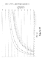
本発明の幾つかの実施形態において、上記装置のアウトプット(出力)は、複数のエンドポイント(終点、終止点)から選択される。一実施形態において、抵抗又は電圧の測定値は、複数の検体の濃度範囲の中の少なくとも1つに対応する。一実施形態において、そのアウトプットは、定量的(量的)、又は半定量的である。他の実施形態において、そのアウトプットは、定性的である。更に、他の実施形態において、上記エンドポイントは、患者の年齢から決定され得る。12歳未満の年齢について、エンドポイントは、(i)20ppb未満の検体濃度範囲、(ii)20ppbと35ppbの間の検体濃度範囲、(iii)35 ppbより大きい検体濃度範囲、の3つの検体濃度範囲と相関がある。12歳より大きい年齢については、そのエンドポイントは、(i)25ppb未満の検体濃度範囲、(ii)25ppbと50ppbの間の検体濃度範囲、(iii)50ppbより大きい検体濃度範囲、の3つの範囲と相関している。他の実施形態において、上記装置は、1つ又は複数のソース(源)から受け取られるインプット(入力)に基づいて、アウトプットのタイプを決定し得る。幾つかの実施において、そのアウトプットは、所定の検体濃度より上または下にある。幾つかの実施形態において、予め設定された検体濃度は、1ppbと50ppbの間にある濃度の範囲から選択される。検体が一酸化窒素である時、上記予め設定された検体濃度は、好ましくは、20ppb、25ppb、30ppb、35ppb、40ppb、50ppbであることができる。検体がメタンである時、上記予め設定された検体濃度は、好ましくは、15ppm又は20ppmである。検体が水素である時、上記予め設定された検体濃度は、好ましくは、15ppm又は20ppmである。 In some embodiments of the invention, the output of the device is selected from a plurality of endpoints (end points, end points). In one embodiment, the resistance or voltage measurement corresponds to at least one of the concentration ranges of the plurality of specimens. In one embodiment, the output is quantitative (quantitative) or semi-quantitative. In other embodiments, the output is qualitative. Moreover, in other embodiments, the endpoint may be determined from the age of the patient. For ages under 12 years, the endpoints are three sample concentrations: (i) sample concentration range <20 ppb, (ii) sample concentration range between 20 ppb and 35 ppb, and (iii) sample concentration range greater than 35 ppb. Correlates with range. For ages older than 12 years, the endpoints are (i) a sample concentration range of less than 25 ppb, (ii) a sample concentration range between 25 ppb and 50 ppb, and (iii) a sample concentration range greater than 50 ppb. Correlates with. In other embodiments, the device may determine the type of output based on the inputs received from one or more sources. In some practices, the output is above or below a given sample concentration. In some embodiments, the preset sample concentration is selected from a concentration range between 1 ppb and 50 ppb. When the sample is nitric oxide, the preset sample concentration can preferably be 20ppb, 25ppb, 30ppb, 35ppb, 40ppb, 50ppb. When the sample is methane, the preset sample concentration is preferably 15 ppm or 20 ppm. When the sample is hydrogen, the preset sample concentration is preferably 15 ppm or 20 ppm.
(テストストリップ - 一般)
その最も基本的な観点(レベル)において、上記テストストリップは、基板/ベースと、感知ケミストリーとから構成されている。そのテストストリップの実施形態は、基板と、電気接続を確立する手段(つまり、電極)と、少なくとも1つの感知ケミストリーと、任意的に、少なくとも1つの付加的な層と、を含む。その形態とデザインとは、対象のガスと、テストストリップが配置されるであろう環境とに基づいて、変更され得る。感知ケミストリーは、対象のガスに基づいて、選択される。そして、電極は、検体との相互作用中に生じる、その感知ケミストリーの特性(性質)の変化を測定するように、構成される。上記1つ又は複数の層は、その感知物質及び感知ケミストリーの為の支持、検体の感知、ケミストリーのデポジション(堆積、沈積、蒸着、成膜、deposition)用のマスキング、複数の層間のアドヒージョン(粘着、接着、付着、adhesion)、干渉物質からの保護、上記テストストリップの選択性及び/又は感受性の向上(増大)、上記感知ケミストリーの保護、及びスペーシング(間隔あけ)を含む複数の目的に役立つことができるが、これらの目的に限定されない。層は、その流体サンプルの少なくとも一部分が通過することを許容する為のウインドーや孔(穴)等の特徴を含み得る。上記電極、ケミストリー及び層に関する詳細は、以下に記載される。
(Test strip--general)
From its most basic point of view (level), the test strip is composed of a substrate / base and sensing chemistry. Embodiments of the test strip include a substrate, means for establishing electrical connections (ie, electrodes), at least one sensing chemistry, and optionally at least one additional layer. Its form and design can be modified based on the gas of interest and the environment in which the test strip will be placed. Sensing chemistry is selected based on the gas of interest. The electrodes are then configured to measure changes in the properties of their sensing chemistry that occur during interaction with the specimen. The one or more layers may include support for its sensing material and sensing chemistry, sample sensing, masking for chemistry deposition (deposition, deposition, deposition, deposition, deposition), and interference between multiple layers (deposition). For multiple purposes including adhesion (adhesion), protection from interfering substances, increased selectivity and / or sensitivity (increased) of the test strips, protection of the sensed chemistry, and spacing (spacing). It can be useful, but not limited to these purposes. The layer may include features such as windows and holes to allow at least a portion of the fluid sample to pass through. Details regarding the electrodes, chemistry and layers are described below.
幾つかの実施形態において、上記テストストリップは、1回用(使い捨て)である。幾つかの実施形態において、上記テストストリップは、複数回用である。幾つかの実施形態において、上記テストストリップは、使用が制限されている。更に、他の実施形態において、上記テストストリップは、3回以下の使用に用いられ得る。 In some embodiments, the test strip is a one-time use (disposable). In some embodiments, the test strip is for multiple uses. In some embodiments, the test strips have limited use. Furthermore, in other embodiments, the test strip can be used for up to 3 uses.
一実施形態において、上記テストストリップは、表示するべきアウトプットのタイプを上記装置に示す特定の抵抗の電極又は特定の形態の電極を有し得る。他の実施形態において、バーコードが、表示するべきアウトプットのタイプを決定するのに用いられる。このバーコードは、本発明の精神から逸脱することなく、どのような数の箇所にも設けられ得る。例としては、上記テストストリップ又はパッケージを含むが、これらのものに限定されない。他の実施形態において、チップが、その装置内に挿入され、これにより、複数のアウトプットの少なくとも1つに関する情報が提供される。他の実施形態において、そのアウトプットのタイプは、その装置内に、手動で入力される。 In one embodiment, the test strip may have an electrode of a particular resistance or an electrode of a particular form indicating the type of output to be displayed on the device. In other embodiments, barcodes are used to determine the type of output to be displayed. This barcode can be placed in any number of places without departing from the spirit of the invention. Examples include, but are not limited to, the test strips or packages described above. In another embodiment, the chip is inserted into the device, which provides information about at least one of the plurality of outputs. In other embodiments, the type of output is manually entered into the device.
他の実施形態において、上記バーコード又は上記チップは、又、上記装置が特定の校正表(キャリブレーションテーブル)を用いることを可能にし得る。他の実施形態において、そのバーコード又はチップは、校正表に関する情報を含み得る。 In other embodiments, the barcode or chip may also allow the device to use a particular calibration table. In other embodiments, the barcode or chip may contain information about the calibration table.
他の実施形態において、上記複数のアウトプットに関する情報、又は校正に関する情報は、対をなすモバイル式の(可動性の)コンピューティングデバイスから受け取られる。 In other embodiments, the information about the plurality of outputs, or the information about calibration, is received from a pair of mobile (mobile) computing devices.
(テストストリップ感知ケミストリー)
多数の感知ケミストリーが、本発明の精神から逸脱することなく、可能である。一実施形態において、その感知ケミストリーは、検体に結合するように機能化(官能基化 functionalized)されたナノ構造体から構成されており、該ナノ構造体を跨いで(横切って)、電気抵抗の変化を生じる。他の実施形態において、上記検体は、センサー表面で、レドックス反応(酸化還元反応)を生じさせ、それが測定される、他の実施形態において、上記検体は、その感知ケミストリーの電子環境における変化を引き起こし、この結果、測定される光学的特性に変化をもたらす。ナノ構造体は、(単層の、多層の、幾つかの層の)カーボンナノチューブ、グラフェン、グラフェンオキシド、ナノワイヤー等を含み得るが、これらのものに限定されない。このナノ構造体は、組み立てられて、例えば、紙、泡(フォーム)、フィルム等のマクロ的(巨視的)な特徴をなすことができる。或いは、このナノ構造体は、マクロ組織内に埋め込まれるか、又は該マクロ組織上にデポジット(堆積、沈積、蒸着、成膜、deposited)されることができる。例としての官能基化物質(functionalization materials)は、次のものを含む。
複素環マクロサイクル
例としては、クラウンエーテル、フタロシアニン、ポルフィリン等を含むが、これらのものに限定されない。
金属酸化物
例としては、AgO,CeO2,CO2O3,CrO2,PdO,RuO2,TiO2を含むが、これらのものに限定されない。
遷移金属
例としては、Ag,Cu,Co,Cr,Fe,Ni,Pt,Ru,Rh,Tiを含むが、これらのものに限定されない。
カルボニル基
例としては、カルボン酸、アミド類、アルデヒド類等を含むが、これらのものに限定されない。
機能性有機系色素(functional organic dyes)
例としては、アゾ染料、シアニン、フルオロン、インジゴ染料、フォトクロミック染料、フタロシアニン、キサンテン誘導体等を含むが、これらのものに限定されない。
(Test strip sensing chemistry)
Numerous sensing chemistries are possible without departing from the spirit of the invention. In one embodiment, the sensing chemistry is composed of nanostructures that have been functionalized to bind to the specimen, straddling (crossing) the nanostructures and of electrical resistance. Make a change. In other embodiments, the sample causes a redox reaction (oxidation-reduction reaction) on the surface of the sensor, which is measured. In other embodiments, the sample exhibits changes in its sensing chemistry in an electronic environment. It causes, and as a result, changes in the measured optical properties. Nanostructures may include, but are not limited to, carbon nanotubes (single-layer, multi-layer, several layers), graphene, graphene oxide, nanowires and the like. The nanostructures can be assembled to form macroscopic features such as paper, foam, film and the like. Alternatively, the nanostructures can be embedded within the macrostructure or deposited on the macrostructure. Functionalization materials as an example include:
Examples of the heterocyclic macrocycle include, but are not limited to, crown ethers, phthalocyanines, porphyrins and the like.
Examples of metal oxides include, but are not limited to, AgO, CeO 2 , CO 2 O 3 , CrO 2 , PdO, RuO 2 , TiO 2 .
Examples of transition metals include, but are not limited to, Ag, Cu, Co, Cr, Fe, Ni, Pt, Ru, Rh, Ti.
Examples of the carbonyl group include, but are not limited to, carboxylic acids, amides, aldehydes and the like.
Functional organic dyes
Examples include, but are not limited to, azo dyes, cyanine, fluorones, indigo dyes, photochromic dyes, phthalocyanines, xanthene derivatives and the like.
上記機能化されたナノ構造体(機能を有するナノ構造体)は、ここでは、感知ケミストリーと称されるが、これは、基板上に設けられて、テストストリップの基礎的(基本的)なコンポーネントを形成する。電極は、下記のように、上記感知ケミストリーと通信状態にある。 The functionalized nanostructures (functional nanostructures) are referred to herein as sensing chemistry, which are provided on the substrate and are the basic (basic) components of the test strip. To form. The electrodes are in communication with the sensing chemistry as described below.
感知ケミストリーとは、検体に暴露された時に、物理的特性を変化させる、1種類の化合物(a compound)、若しくは複数種類の化合物の組み合わせ(a set of compounds)、を意味している。その物理的特性は、電気信号に変換されることができ、そして、該物理的特性は、抵抗、電圧、又は電流の中の少なくとも1つとして、測定されることができる。この感知ケミストリーは、アクティブであることができる。該アクティブとは、対象の1つの検体又は複数の検体に反応するように、又は基準となる感知ケミストリー(a reference sensing chemistry)に反応するように、デザインされていることを意味している。基準となる感知ケミストリーは、少なくとも1つの検体との相互作用から保護されているか、若しくは、少なくとも、対象の検体には反応しない、1種類の化合物(a compound)、若しくは複数種類の化合物の組み合わせ(a set of compounds)である。 Sensing chemistry means one type of compound (a compound) or a set of compounds that changes physical properties when exposed to a sample. Its physical properties can be converted into electrical signals, and the physical properties can be measured as at least one of resistance, voltage, or current. This sensing chemistry can be active. The active means that it is designed to react to one or more specimens of interest, or to respond to a reference sensing chemistry. The reference sensing chemistry is protected from interaction with at least one sample, or at least one compound that does not react with the sample of interest, or a combination of multiple compounds (a compound). a set of compounds).
他の実施形態において、上記感知ケミストリーは、機能化されていない(つまり、敏感にされない)ナノ構造体である。この実施形態は、機能化されたナノ構造体に関連して用いられ得るか、又はスタンドアロン(独立型、単独型)であり得る。 In other embodiments, the sensing chemistry is a non-functionalized (ie, non-sensitive) nanostructure. This embodiment can be used in connection with functionalized nanostructures or can be stand-alone (stand-alone, stand-alone).
補助的な(二次的な)添加剤を用いて、基板上でのデポジションに関し、上記感知ケミストリーの乾燥特性と加工性とに影響を及ぼし得る。デポジション法(堆積法)の非制限的な例は、図16に一覧表を載せている。添加剤は、粘度(粘性)、表面張力、湿潤性、アドヒージョン、乾燥時間、ゲル化、膜厚の均一性等を変化させる為に、用いられ得る。これらの添加剤は、二次溶剤、増粘剤(濃厚剤 thickners)、塩、及び/又は、界面活性剤を含むが、これらのものに限定されない。これらの添加剤は、1つ又は複数の目的に仕え得る。例としては、図16におけるものと、次のものとを含み得るが、これらのものに限定されない。
増粘剤 - 重合体及び非重合体
グリセリン
ポリプロピレングリコール
界面活性剤 - イオン性及び非イオン性
ドデシル硫酸ナトリウム
トリトンX-100
Auxiliary (secondary) additives can be used to affect the drying properties and processability of the sensing chemistry with respect to deposition on the substrate. Non-limiting examples of the deposition method are listed in FIG. Additives can be used to change viscosity (viscosity), surface tension, wettability, adhesion, drying time, gelation, film thickness uniformity, and the like. These additives include, but are not limited to, secondary solvents, thickeners (thickeners), salts, and / or surfactants. These additives may serve one or more purposes. Examples may include, but are not limited to, those in FIG. 16 and:
Thickener-Polymer and Non-Polymer Glycerin Polypropylene Glycol Surfactant-Ionic and Nonionic Dodecyl Sulfate Triton X-100
幾つかの実施形態において、上記基板上に設けられる感知ケミストリーの体積は、物質(材料、material)の1ミリリットル以下であり得る。 In some embodiments, the volume of sensing chemistry provided on the substrate can be less than 1 milliliter of material.
幾つかの実施形態において、上記感知ケミストリーは、測定の為の特定の条件下において、上記対象の検体に不可逆的に結合する。不可逆的な相互作用の例としては、共有結合、イオン間相互作用、又は大きな平衡定数を有する非共有結合相互作用、例えば、配位結合、双極子間相互作用、イオン交換反応、又は水素結合ネットワーク等を含むが、これらのものに限定されない。ここで用いられているように、上記センサーが上記検体に暴露されるのを止めた後に、適切な動作条件の範囲内で関連する時間スケールにわたって信号の回復が皆無かそれに近い場合には、1つの結合は、不可逆的だと考えられる(例えば、分配係数は、0.5未満である)。新しい検体に対する更なる暴露時に、そのセンサーは或る度合いの感度を保持していることが、期待される。幾つかの実施形態において、上記条件の範囲は、通常動作の間にそのセンサーが暴露される条件、例えば、通常の動作レベルの温度、圧力、湿度、光暴露等、を含む。関連する時間スケールに関して、理想的には、不可逆的システムは、その初期のベースラインに100%回復することはない。1つの実施において、或るセンサーは、該センサーが最早その検体に暴露されなくなった後に、感知時間の2倍で、10%未満、回復する。このように、もし、その感知時間が3日である場合には、不可逆的結合システムに関する、そのセンサー信号は、そのセンサーが最早その検体に暴露されなくなった後の6日で10%未満減少し、その初期のベースラインに完全には回復しないであろう。同様に、もし、感知時間が10秒である場合には、その信号は、検体からの取り外しに続く20秒で、10%未満、減少し、その初期のベースラインに完全には回復しないであろう。不可逆的結合を表現する他の方法は、結合箇所の数が、その検体によって飽和されてしまうポイント(時点)迄は、その結合が決して定常状態の平衡には達しない、ということである。むしろ、検体は、各追加的な暴露によって、そのセンサー上に蓄積してゆく。 In some embodiments, the sensing chemistry irreversibly binds to the sample of interest under certain conditions for measurement. Examples of irreversible interactions are covalent bonds, ion-ion interactions, or non-covalent bonds with large equilibrium constants, such as coordination bonds, dipole interactions, ion exchange reactions, or hydrogen bond networks. Etc., but not limited to these. As used herein, 1 if there is no or near signal recovery over the relevant time scale within the appropriate operating conditions after the sensor has stopped being exposed to the specimen. The two bonds are considered irreversible (eg, the partition coefficient is less than 0.5). It is expected that the sensor will retain some sensitivity upon further exposure to new specimens. In some embodiments, the range of conditions includes conditions under which the sensor is exposed during normal operation, such as temperature, pressure, humidity, light exposure, etc. at normal operating levels. Ideally, an irreversible system does not recover 100% to its initial baseline with respect to the associated time scale. In one practice, a sensor recovers less than 10% at twice the sensing time after the sensor is no longer exposed to the specimen. Thus, if the sensing time is 3 days, the sensor signal for the irreversible coupling system is reduced by less than 10% 6 days after the sensor is no longer exposed to the specimen. , Will not fully recover to its initial baseline. Similarly, if the sensing time is 10 seconds, the signal will decrease by less than 10% in the 20 seconds following removal from the specimen and will not fully recover to its initial baseline. Let's go. Another way to express irreversible binding is that the binding never reaches steady-state equilibrium until the number of binding sites is saturated by the sample. Rather, the specimen accumulates on its sensor with each additional exposure.
幾つかの実施形態において、その感知面を去る結合された分子の割合(比率、fraction)が、例えば、0.5未満である時、検体は、上記感知ケミストリーに不可逆的に結合されている、と考えられる。この割合は、ここでは、分配係数(partition coefficient)と称される。この分配係数は、そのアプリケーションの使用温度における、その検体に対する暴露を終えた後の、その感知面を去る結合された検体の分子の割合として、定義される。一実施形態において、上記分配係数は、0.5未満である。他の実施形態において、上記分配係数は、0.25未満である。他の実施形態において、上記分配係数は、0.1未満である。他の実施形態において、上記分配係数は、0.05未満である。更に、他の実施形態において、上記分配係数は、0.01未満である。 In some embodiments, when the percentage of bound molecules leaving the sensing surface is, for example, less than 0.5, the specimen is considered to be irreversibly bound to the sensing chemistry. Be done. This ratio is referred to herein as the partition coefficient. This partition coefficient is defined as the percentage of molecules of the bound specimen that leave the sensing surface after exposure to the specimen at the operating temperature of the application. In one embodiment, the partition coefficient is less than 0.5. In other embodiments, the partition coefficient is less than 0.25. In other embodiments, the partition coefficient is less than 0.1. In other embodiments, the partition coefficient is less than 0.05. Furthermore, in other embodiments, the partition coefficient is less than 0.01.
上記ケミストリーの上記不可逆的性質により、幾つかの実施形態において、テストストリップが使用される度に、前回の測定からの検体の殆どは、そのテストストリップ上に留まっている。従って、各測定前には、ベースライン測定が行われる。幾つかの実施形態において、その初期のベースラインが、又、ケアーの時点で、或いは使用の時点で、取られる。これは、温度、湿度、及び圧力等の周囲条件が、幾つかのタイプの測定に影響を及ぼし得るからである。このベースライン測定に続いて、そのセンサーは、検体に暴露され、測定が行われる。その信号は、そのベースラインと比較されたときの相対的変化として、又は絶対的な変化として、測定され得る。 Due to the irreversible nature of the chemistry, in some embodiments, each time a test strip is used, most of the specimens from previous measurements remain on the test strip. Therefore, a baseline measurement is performed before each measurement. In some embodiments, the initial baseline is also taken at the time of care or at the time of use. This is because ambient conditions such as temperature, humidity, and pressure can affect some types of measurements. Following this baseline measurement, the sensor is exposed to the specimen and the measurement is made. The signal can be measured as a relative change or as an absolute change when compared to its baseline.
幾つかの実施形態において、そのテストストリップは、使い捨てである。これは、その感知ケミストリーが、検体に一度暴露した後(単一暴露の後)に、飽和することを意味している。幾つかの実施形態において、そのテストストリップは、複数回用である。これは、その感知ケミストリーが、検体に一度暴露した後には、飽和しないことを意味している。代わって、この感知ケミストリーは、各暴露をもって検体を蓄積し、該感知ケミストリーは、それが複数回暴露されてしまう迄は、飽和されない。幾つかの実施形態において、上記検体は、該検体に対して365回の暴露の後に、その感知ケミストリーを飽和させる。幾つかの実施形態において、上記検体は、該検体に対して52回の暴露の後に、その感知ケミストリーを飽和させる。幾つかの実施形態において、上記検体は、該検体に対して12回の暴露の後に、その感知ケミストリーを飽和させる。 In some embodiments, the test strip is disposable. This means that the sensing chemistry is saturated after one exposure to the specimen (after a single exposure). In some embodiments, the test strip is for multiple uses. This means that the sensing chemistry does not saturate once exposed to the specimen. Instead, this sensing chemistry accumulates specimens with each exposure, and the sensing chemistry is not saturated until it has been exposed multiple times. In some embodiments, the sample saturates its sensing chemistry after 365 exposures to the sample. In some embodiments, the sample saturates its sensing chemistry after 52 exposures to the sample. In some embodiments, the sample saturates its sensing chemistry after 12 exposures to the sample.
(テストストリップ - 基板、電極、感知ケミストリーの形態及び層) (Test strips-boards, electrodes, sensing chemistry morphology and layers)
上記基板、電極、及びケミストリーのデポジションに関して、種々の形態又は組み合わせが、本発明の精神から逸脱することなく、可能である。形態は、上記感知ケミストリー、対象の検体、及びそのユニットが配置されるであろう環境、の特性によって、規定される。感知ケミストリーは、又、化学抵抗ブリッジ回路(chemresistive bridge ciruit)におけるようなレファレンス(基準)を提供するように、(例えば、上記検体との相互作用等の)特定の相互作用を防止する目的で、被覆されるか、又は覆われることができる。多重分析(multiplexed analysis)を目的として、或いは信号の平均値算出を目的として、レファレンスとして働くように、複数の(多数の)感知ケミストリーが使用可能であり、或いは、同一のケミストリーが、一度以上、デポジットされ得る。図17Aは、上記テストストリップの基板、電極、感知ケミストリー及び層についての種々の形態の例を示している。一実施形態1709において、上記テストストリップは、ベース基板1701と、少なくとも1つの電極対1702と、該電極対1702と電気的につながっている少なくとも1つの感知ケミストリー1703と、組み立てられた時1707に少なくとも上記感知ケミストリーを露出させる為のウインドー又は孔(穴)1705を備えた任意的な付加層1704と、から構成されている。該付加層1704は、スペーシング層(間隔をあける層)又は保護層として仕え得る。任意的に、上記テストストリップは、第2の感知ケミストリー1706を有し得る。任意的に、上記テストストリップは、第2の層1708を含まなくても良い。付加層は、その感知ケミストリー、電極の形態、干渉物質、及び製造プロセスに依存する種々の理由により、上記テストストリップ内に組み入れられることができる。例としては、ケミストリーのデポジション用のマスキング、ケミストリーのデポジション用のサポート(支持、支持体)、干渉物質からの保護、そのテストストリップの選択性及び/又は感度の向上、感知ケミストリーとしての機能(acting)、スペーシング、感知ケミストリーの保護、ガスチャンバの形成、テストストリップの剛性、又は構造的形態を含むが、これらのものに限定されない。層は、多孔性及び非多孔性ポリマー、複合材料、紙や繊維ガラス等の繊維状物質、織布及び不織布、メンブレン(膜)、ポリマー、接着剤(粘着剤、adhesives)、フィルム、ゲル等から構成され得る。幾つかの実施形態において、上記層は、例えば、化学的に処理することにより、又はコーティングすることにより、及び/又は機械的に変更することにより、修正(手直し、modified)され得る。上記層は、1つ、又は2つ以上の目的に仕え得る。例えば、幾つかの実施形態において、1つの層は、構造的コンポーネントとして(例えば、剛性を改善したり、スペーサーとして)、又、選択的にガスを透過させるメンブレンとして、仕え得る。他の例において、1つの層は、構造的コンポーネント(例えば、スペーサー又は保護層)として働くことができ、又、該1つの層は、更に、ウインドーを形成(画定)することができ、これにより、上記対象の検体は、上記感知ケミストリー及び/又はレファレンスケミストリー(上記レファレンスとなるケミストリー)に到達可能になる。複数の層は、互いに関連して用いられることができ、これにより、上記テストストリップを干渉物質から保護する一方で、対象となるガスの選択的透過が実現される。幾つかの実施形態において、上記電極上には、絶縁体層(誘電体層)が設けられる。
Various forms or combinations of the substrates, electrodes, and chemistry deposition are possible without departing from the spirit of the invention. Morphology is defined by the characteristics of the sensing chemistry, the specimen of interest, and the environment in which the unit will be located. Sensing chemistry is also intended to prevent certain interactions (eg, interactions with the specimens, etc.) so as to provide a reference, such as in a chemresistive bridge circuit. It can be covered or covered. Multiple (many) sensing chemistries may be used, or the same chemistry may be used more than once, to act as a reference for the purpose of multiplexed analysis or for the purpose of calculating the mean value of a signal. Can be deposited. FIG. 17A shows examples of various forms of the test strip substrate, electrodes, sensing chemistry and layers. In one
図17Bと図17Cは、上記テストストリップの1つの層上の基板、電極及び感知ケミストリーの種々の形態の例1701~1712及び1722~1726を示している。 17B and 17C show examples 1701-1712 and 1722-1726 of various forms of substrates, electrodes and sensing chemistry on one layer of the test strip.
一実施形態1701において、基板1713は、1つの面上に、電極1714と、該電極1714に交差してデポジットされた感知ケミストリー1715とを有する。基板1716の裏面も、又、電極と感知ケミストリーとを有する。基板1716の裏面は、対称的又は非対称的であることができる。非対称は、異なる感知ケミストリー
、異なるケミストリー形態、又は異なる電極形態等、を含むことができる。その第2の感知ケミストリー1717は、第1の感知ケミストリー1715に対して、同一であっても、異なっていても良い。これは、対象の検体に対する、感度と選択性との調整に用いられ得る。他の実施形態1708において、2つのテストストリップ1731,1732が、別々に、製造され、次いで、分離した1つの基板1718上に集合せしめられて(組み立てられて)、完成したテストストリップを形成する。これは、その感知ケミストリーが異なっている場合に、製造の容易さを増す為に、なされ得る。上記感知ケミストリーが横並び1709になっている他の実施形態において、その2つの感知ケミストリーの一方は、被覆1721されている。他の実施形態1710は、列をなしたケミストリーを有する。他の実施形態1711において、その基板1722は、感知ケミストリーへのガス1721aの通過を許容する。これは、記載されているように、そのテストストリップが、そのガスストリームから外方を向いて設けられることを許容する。追加的な形態の例1722及び1723が、そのテストストリップ上で1つの電極を共有してオフセットしている(中心線を外して設けられている、中心線から逸らせて設けられている)2つのケミストリーをもって、示されている。一例1723において、これらの2つのケミストリーの一方は、被覆されている。他の実施形態1724において、複数の感知ケミストリーが示されている。この例において、それらのケミストリーは、少なくとも1つの電極を共有し得る。他の実施形態1725において、それらの複数のケミストリーの少なくとも1つが、被覆されている。他の実施形態1726は、3つの電極をブリッジする1つのケミストリーを示している。この実施形態において、それらの3つの電極は、作用電極と、レファレンス電極と、対向電極を表し得る。
In one
図17Dは、より複雑な構成の実施形態を示している。幾つかの実施形態1727,1728及び1729において、一体型ヒーター(一体化されたヒーター)1731,1733,1734が、そのテストストリップ内の、感知ケミストリー1732a,1732b,1732cと同じ(1728で示すような)層上に、又は、異なる(1727で示すような)層上に、組み込まれている。他の実施形態1729において、そのテストストリップは、少なくとも1つの層上に、付加的なセンサーエレメント1735と、一体型電子装置1736と、を有する。付加的なセンサーエレメント1735の例としては、温度センサー、及び/又は湿度センサーを含み得るが、これらのものに限定されない。一体型電子装置1736の例としては、レジスター(抵抗器)、フューズ、キャパシター(コンデンサー、蓄電器)、スイッチ等を含み得るが、これらのものに限定されない。上記テストストリップは、又、(不図示の)用途の数を管理又は制御する為の手段を含み得る。例としては、RFID、バーコード、バーンアウト回路又はバーンアウトフューズ、テストストリップ上のメモリー、通し番号、スイッチ等を含む。
FIG. 17D shows an embodiment of a more complex configuration. In some
図18Aは、複数(多数)の層を備えたテストストリップの例を示している。層は、感知ケミストリー、電極形態、干渉物質、及び製造プロセスに依存する様々な理由により、テストストリップ内に組み込まれることができる。例としては、ケミストリーのデポジション用のマスキング、ケミストリーのデポジション用のサポート、干渉物質からの保護、上記テストストリップの選択性及び/又は感度の向上、感知ケミストリーとしての機能、スペーシング、ガスチャンバの形成、テストストリップの剛性、又は構造的形態を含むが、これらのものに限定されない。層は、多孔性及び非多孔性ポリマー、複合材料、紙や繊維ガラス等の繊維状物質、織布及び不織布、メンブレン、ポリマー、接着剤(粘着剤、adhesives)、フィルム、ゲル等から構成され得る。幾つかの実施形態において、上記層は、例えば、化学的に処理することにより、又はコーティングすることにより、及び/又は機械的に変更することにより、修正(手直し、modified)され得る。上記層は、1つ、又は2つ以上の目的に仕え得る。例えば、幾つかの実施形態において、1つの層は、構造的コンポーネントとして(例えば、剛性を改善したり、スペーサーとして)、又、選択的にガスを透過させるメンブレンとして、仕え得る。複数の層は、互いに関連して用いられることができ、これにより、上記テストストリップを干渉物質から保護する一方で、対象となるガスの選択的透過が実現される。幾つかの実施形態において、上記電極上には、絶縁体層(誘電体層)が設けられる。 FIG. 18A shows an example of a test strip with multiple layers. Layers can be incorporated into test strips for a variety of reasons depending on sensing chemistry, electrode morphology, interfering substances, and manufacturing process. Examples include masking for chemistry deposition, support for chemistry deposition, protection from interfering substances, increased selectivity and / or sensitivity of the test strips, functioning as sensing chemistry, spacing, gas chambers. Includes, but is not limited to, the formation of, the rigidity of the test strip, or the structural form. The layer may be composed of porous and non-porous polymers, composite materials, fibrous materials such as paper and fibrous glass, woven and non-woven fabrics, membranes, polymers, adhesives (adhesives, adhesives), films, gels and the like. .. In some embodiments, the layer can be modified (modified), for example, by chemical treatment or coating, and / or by mechanical modification. The layer may serve one or more purposes. For example, in some embodiments, one layer can serve as a structural component (eg, to improve stiffness or as a spacer) and as a membrane that selectively permeates gas. Multiple layers can be used in association with each other, which protects the test strip from interfering substances while providing selective permeation of the gas of interest. In some embodiments, an insulator layer (dielectric layer) is provided on the electrodes.
デユアルチャンバの例1821に示されるように、スペーシング層1825は、又、単一のチャンバ又は複数のチャンバ1826を形成する為に用いられ得る。このスペーシング層1825は、電極と感知ケミストリーとを備えた基板1827上に設けられる。それらのチャンバは、均一に被覆されても、異なるように被覆1835されても、良い。一実施形態において、上記異なるように被覆されたチャンバは、異なるガスが、その感知ケミストリーに検知されるようにする為に、異なるチャンバ内に拡散することを許容する。他の実施形態1822において、ガス選択層1830が、電極と感知ケミストリーとを有する基板1827上に設けられている。そのスペーシング層1825は、小さい単一のチャンバ1829を有しており、該スペーシング層1825は、上記ガス選択層1830上に設けられている。湿気バリアー1828が、上記スペーシング層上に設けられており、その小さいチャンバ1829を覆っている。他の実施形態1823において、2つのスペーシング層1825が用いられている。これらの2つのスペーシング層は、ガスがセンサー表面で蓄積するようにする為のより大きいチャンバを形成する為に、又は複数の拡散層を分離する為に、用いられ得る。上記スペーシング層は、又、上記テストストリップ及びその層の為の構造的支持体として、役立ち得る。ナフィオン層1833が、上記電極と感知ケミストリーとを有する基板1827上に設けられている。スペーシング層1825は、そのナフィオン層1833上に設けられている。選択的拡散層1832が、第1の上記スペーシング層1825上に設けられている。第2のスペーシング層1825が、上記選択的拡散層1832上に設けられている。フォイルバリアー(箔バリアー)1831が、上記第2のスペーシング層1825上に設けられている。他の実施形態1824において、複数の層の異なる組み合わせが用いられる。選択的透過層1833が、上記電極と感知ケミストリーとを有する基板1827上に設けられている。2つの選択的拡散層1832と、1つのプラグ1834とが、上記スペーシング層1825上に設けられている。一実施形態において、上記プラグ1834は、テストストリップがチャンバ内に挿入された時に、シーリング機構(密閉機構)として機能する。
As shown in Example 1821 of the dual chamber, the
層は、幾つかのガスに対して反応するようにデザインされ得る。 The layer can be designed to react to several gases.
上記層は、それらのものに限定されないが、図16に例示された複数の方法を含む、種々のコーティング法(塗工法)によって、塗布され得る。 The layers can be applied by various coating methods (coating methods), including but not limited to those, including the plurality of methods exemplified in FIG.
干渉の例としては、ガス、濃縮された液体(condensed liquids)、溶解した固体、微粒子物質(微粒子材料)、湿気、温度変化等を含み得るが、これらのものに限定されない。呼気における一酸化窒素の測定の例において、干渉の例は、次のものを含み得る。 Examples of interference may include, but are not limited to, gas, condensed liquids, dissolved solids, particulate matter (fine particle material), moisture, temperature changes, and the like. In the example of measuring nitric oxide in exhaled breath, examples of interference may include:
呼気における一酸化窒素の測定に関連する干渉物質(妨害物質、Interfering Substances)

図18Bは、一実施形態を説明している。この例1800において、そのテストストリップは、電極1806及び感知ケミストリー1808及びレファレンスケミストリー1807を備えたベース基板1801と、任意的な絶縁体層1802と、上記レファレンスケミストリーを覆い且つ上記感知ケミストリーを露出1810する層1803と、メンブレン層(膜層)1804と、保護層1805と、を有している。該保護層1805は、ガスが上記メンブレン層1804に流動することを許容する手段を用いている。一実施形態において、そのメンブレン層1804は、シリコーンを含有している。
FIG. 18B illustrates one embodiment. In this example 1800, the test strip covers the reference chemistry and exposes the sensing chemistry to a
図18Cは、組み立てられたテストストリップの例を説明している。1812は、完全に組み立てられたテストストリップを示している。実施形態1813は、コンパニオン装置との穿刺用フォイルバリアーを有するテストストリップを示している。実施形態1814は、手で除去するタブを備えたフォイルバリアーを有するテストストリップを示している。実施形態1815は、テストストリップそれ自体の上ではなくて、測定ユニット内に電極を備えたテストストリップを示している。この後の実施形態において、コンパニオン装置に設けられている電極は、その装置とテストストリップとがかみ合った時に、該テストストリップ上の感知ケミストリーに当接する。
FIG. 18C illustrates an example of an assembled test strip. 1812 shows a fully assembled test strip.
他の実施形態において、上記ヒーター、付加的なセンサーエレメント、及びここに記載されている一体型電子装置は、そのリーダーメーター(リーダー計器、reader meter)内に組み込まれる。 In other embodiments, the heater, additional sensor elements, and the integrated electronic device described herein are incorporated within the reader meter.
他の実施形態において、上記ヒーター、付加的なセンサーエレメント、及びここに記載されている一体型電子装置は、そのリーダー内、及び/又は上記テストストリップが配置されているところのチャンバ内、に組み込まれる。 In other embodiments, the heater, additional sensor elements, and the integrated electronic device described herein are incorporated within its reader and / or in the chamber where the test strip is located. Is done.
(不図示の)他の例は、電気化学反応を測定するのに適した電極形態(つまり、作用電極、対向電極(counter electrode)、レファレンス電極)を有し得る。 Other examples (not shown) may have electrode morphology suitable for measuring electrochemical reactions (ie, working electrode, counter electrode, reference electrode).
一実施形態において、上記テストストリップは、1つの基板、少なくとも1つの電極、少なくとも1つの感知ケミストリー、及び、任意に、その感知ケミストリーを干渉物質から保護する為の少なくとも1つの層、から構成され得る。その感知領域は、1つ以上の電気接点と電気的につながっている少なくとも2つのナノネットワークから構成され得る。1つのネットワークは、能動的感知ケミストリーとして機能し、特定の1組の検体(例えば、一酸化窒素又は二酸化窒素)に対しては敏感であろう。付加的なネットワークは、異なる検体用のセンサーとしてのレファレンスとして機能するか、又は信号の平均値算出の為の同一の検体用のセンサーとしてのレファレンスとして機能するか、のいずれかであろう。上記レファレンスは、上記能動的感知ケミストリーと上記レファレンスとの間の差分信号(差動信号、differential signal)が、単一の検体、又は小さい1組の検体、又は1サブセットの検体、に向けての信号感度(signal sensitivity)であって、該信号感度をもってそのテストストリップが敏感であるところの信号感度、に帰着するように、異なる1組の検体に対して、敏感であり得る。多重分析のケースにおいては、2つ以上のレファレンスが存在し得る。 In one embodiment, the test strip may consist of one substrate, at least one electrode, at least one sensing chemistry, and optionally at least one layer to protect the sensing chemistry from interfering substances. .. The sensing area may consist of at least two nanonetworks that are electrically connected to one or more electrical contacts. One network will act as an active sensing chemistry and will be sensitive to a particular set of specimens (eg, nitric oxide or nitrogen dioxide). The additional network will either serve as a reference as a sensor for different specimens, or as a reference as a sensor for the same specimen for calculating the mean value of the signal. In the reference, the difference signal (differential signal) between the active sensing chemistry and the reference is directed to a single sample, a small set of samples, or a subset of samples. It may be sensitive to different sets of specimens such that it results in signal sensitivity, where the test strip is sensitive with that signal sensitivity. In the case of multiple analysis, there can be more than one reference.
他の実施形態において、上記テストストリップは、1つの基板と、少なくとも1つの電極と、少なくとも1つの感知ケミストリーと、任意に、その感知ケミストリーを干渉物質から保護する為の少なくとも1つの層と、から構成され得る。その感知領域は、2つ以上の電極間にデポジットされた、少なくとも2つのナノネットワークから構成され得る。1つのネットワークは、能動的感知ケミストリーとして機能し、特定の1組の検体(例えば、一酸化窒素、二酸化窒素、二酸化炭素、水素、又はメタン)に対して敏感であろう。第2のネットワークは、レファレンスとして機能するであろう。該レファレンスは、能動的ナノネットワークとして、同一の感知ケミストリーから構成され得る。そして、このレファレンスは、被覆されていても、被覆されていなくても良い。上記テストストリップと、ケミストリーとは、抵抗性回路としても、ブリッジ回路としても、構成され得る。 In other embodiments, the test strip comprises one substrate, at least one electrode, at least one sensing chemistry, and optionally at least one layer to protect the sensing chemistry from interfering substances. Can be configured. The sensing area may consist of at least two nanonetworks deposited between two or more electrodes. One network will act as an active sensing chemistry and will be sensitive to a particular set of specimens (eg, nitric oxide, nitrogen dioxide, carbon dioxide, hydrogen, or methane). The second network will serve as a reference. The reference can be composed of the same sensing chemistry as an active nanonetwork. And this reference may or may not be coated. The test strip and the chemistry can be configured as a resistance circuit or a bridge circuit.
幾つかの実施形態において、上記能動的ケミストリーと、感知ケミストリーとは、その基板上でのデポジション前に、プレミックス(予備混合)される。幾つかの実施形態において、その能動的ケミストリーと感知ケミストリーとは、4ステップ(工程)以下のステップ(工程)で、デポジットされる。 In some embodiments, the active chemistry and the sensing chemistry are premixed prior to deposition on the substrate. In some embodiments, the active chemistry and the sensing chemistry are deposited in 4 steps or less.
本発明の幾つかの実施形態において、そのテストストリップは、クロマトグラフィー層を有する。クロマトグラフィー層は、サンプル内における複数の検体(例えば、息と周囲空気)の中の少なくとも1つが、他の複数の検体の移動に対して、異なる速度で、このクロマトグラフィー層内を移動することを許容する。 In some embodiments of the invention, the test strip has a chromatographic layer. A chromatographic layer is one in which at least one of a plurality of specimens (eg, breath and ambient air) in the sample moves within the chromatographic layer at a different rate with respect to the movement of the other plurality of specimens. Tolerate.
本発明の1つのアスペクトは、複数の検体を含む流体サンプル内における少なくとも1つの検体の濃度を測定する為のシステムを提供する。このシステムは、ベース基板と、該ベース基板上に設けられた第1電極対と、上記第1電極対と電気的に通じており、サンプル内における少なくとも1つの検体に反応する第1感知ケミストリーと、少なくとも1つの感知ケミストリー上に設けられた第1クロマトグラフィー層とを備え、上記複数の検体の中の少なくとも1つ検体は、上記第1クロマトグラフィー層内を、上記複数の検体の中の他の複数の検体の移動に対して異なる速度で移動する。 One aspect of the invention provides a system for measuring the concentration of at least one sample in a fluid sample containing multiple samples. This system has a base substrate, a first electrode pair provided on the base substrate, and a first sensing chemistry that electrically communicates with the first electrode pair and reacts with at least one sample in the sample. The first chromatographic layer provided on at least one sensing chemistry is provided, and at least one sample among the plurality of samples has the inside of the first chromatography layer and the other among the plurality of samples. It moves at different speeds for the movement of multiple specimens.
他の実施形態において、上記システムは、更に、ブロッキング層と、第2感知ケミストリー上に設けられた第2クロマトグラフィー層、の中の少なくとも1つを有する。ここで、そのブロッキング層は、第2感知ケミストリーと、上記流体サンプル内の少なくとも1つの検体との接触を阻止する。そして、上記複数の検体の中の少なくとも1つの検体は、第2クロマトグラフィー層内を、上記複数の検体の中の他の複数の検体の移動に対して、異なる速度で、移動する。本発明の他のアスペクトは、どのような数のクロマトグラフィー層でも含み得る。 In another embodiment, the system further comprises at least one of a blocking layer and a second chromatographic layer provided on the second sensing chemistry. Here, the blocking layer blocks contact between the second sensing chemistry and at least one sample in the fluid sample. Then, at least one of the plurality of samples moves in the second chromatography layer at a different speed with respect to the movement of the other plurality of samples in the plurality of samples. Other aspects of the invention may include any number of chromatographic layers.
本発明の他のアスペクトは、流体サンプル内における少なくとも1つの検体の濃度を測定する為の方法を提供する。この方法は、ベース基板と、該ベース基板上に設けられた第1電極対と、サンプル内における少なくとも1つの検体に反応する第1感知ケミストリーであって、上記第1電極対と電気的に通じている第1感知ケミストリーと、少なくとも1つの感知ケミストリー上に設けられた第1クロマトグラフィー層であって、該層内を、上記複数の検体の中の少なくとも1つ検体は、上記複数の検体の中の他の複数の検体の移動に対して、異なる速度で、移動する、第1クロマトグラフィー層とを有するシステムを提供するステップと、上記第1電極対に跨る電圧と、上記第1電極対に跨る抵抗と、上記第1電極対に跨る電流の中の少なくとも1つを計測するステップと、を有する。 Another aspect of the invention provides a method for measuring the concentration of at least one sample in a fluid sample. This method is a first sensing chemistry that reacts with a base substrate, a first electrode pair provided on the base substrate, and at least one sample in the sample, and is electrically communicated with the first electrode pair. The first sensing chemistry and the first chromatography layer provided on at least one sensing chemistry, in which at least one of the plurality of specimens is a plurality of specimens. A step of providing a system having a first chromatographic layer that moves at different speeds with respect to the movement of other plurality of specimens in, a voltage across the first electrode pair, and the first electrode pair. It has a resistance straddling the first electrode pair and a step of measuring at least one of the currents straddling the first electrode pair.
図30は、一実施形態のテストストリップ3009であって、クロマトグラフィー分離層を用いて、ガスを検知するように構成されたテストストリップ3009を説明している。このテストストリップは、基板3001と、電極3002と、少なくとも1つの感知ケミストリー3003と、クロマトグラフィーの分離材料(分離物質)3006を含む層3004と、から構成されている。好ましい実施形態において、そのクロマトグラフィーの分離材料3006は、電極対3002をブリッジする感知ケミストリー3003の上に設けられる。そのクロマトグラフィーの分離材料は、他の層内に一体化されるか、又はそれ自体の層としてあり得る。一体化される場合には、上記層3004は、例えば、クロマトグラフィーの材料(物質)の構造的支持を提供し得る一方で、その層3004は、その検体がそのクロマトグラフィー層3008と感知ケミストリー3003とに到達することを可能にする為のウインドー3005を画定(形成)する。完全に組み立てられた、クロマトグラフィー層を備えたテストストリップは、3007に示されている。ここで、クロマトグラフィー層とは、サンプル内の複数の検体の中の少なくとも1つの検体が、クロマトグラフィー(色層分析)の材料内を、その複数の検体の中の他の複数の検体の移動に対し、異なる速度で移動することを可能にするクロマトグラフィーの材料(物質)を含む、あらゆる層を意味している。そのクロマトグラフィーの材料と、あらゆる付加的な層とは、一体化前に、多数の方法で加工処理され得る。加工処理の例としては、型抜き、レーザー切断、キスカット(kiss cutting)、表面エネルギー処置(surface energy modification)(UV照射、プラズマ放電及びコロナ放電、火炎処理又は酸処理によるもの、又はその技術において知られている他の技術)、感圧接着剤を有する接着積層又は感圧接着剤を有さない接着積層による噴霧処理等を含むが、これらのものに限定されない。
FIG. 30 illustrates a
図31は、一実施形態のテストストリップ3109であって、クロマトグラフィー分離層を用いて、ガスを検知するように構成されたテストストリップ3109を説明している。このテストストリップは、基板3101と、電極3102と、(不図示の)任意の絶縁体層と、2つの感知ケミストリー3103と、該感知ケミストリーの一方を覆うと共に第2の(他方の)感知ケミストリーを露出するようにデザインされた層3104と、クロマトグラフィー分離層3106と、そのセンサーをガス又はガス混合物(ガス混合体)に暴露する為のウインドー3108を有する保護層3107と、から構成されている。上記層3104と3107とは、上記検知用のケミストリーの一方を露出する開口3108と3105を形成する多数の方法で、加工処理され得る。加工処理の例としては、型抜き、又はレーザー切断を含むが、これらに限定されない。上記層3104,3106,3107は、該層が一緒にテストストリップに組み立てられる前に、多数の方法で、加工処理され得る。加工処理の例としては、型抜き、レーザー切断、キスカット、表面エネルギー処置(UV照射、プラズマ放電及びコロナ放電、火炎処理又は酸処理によるもの、又はその技術において知られている他の技術)、接着剤による噴霧処理等を含むが、これらに限定されない。
FIG. 31 describes a
他の実施形態において、上記テストストリップは、クロマトグラフィー層としてのみ役立ち、感知要素を含まない(図32)。この実施形態において、クロマトグラフィー層3213を備えた、そのテストストリップは、他のセンサー3214に関連して用いられる。テストストリップに加えて、他のセンサーは、金属酸化物(MOS,CMOS等)センサー、電気化学センサー、光学センサー、MEMSセンサー、FETセンサー、MOSFETセンサー、ChemFETセンサー、又は、その技術において知られている他のタイプのセンサーを含み得る。上記テストストリップ3213は、1回使用、複数回使用、又は限定使用であり得る。それは、使い捨て可能であるか、又は繰り返し使用が可能であり得る。それは、又、一人の患者が使用するものであり得る。クロマトグラフィー層としてのみ役立つ、一実施形態のテストストリップが、3220に示されている。この実施形態において、そのクロマトグラフィー層3217は、2つの基板3216と3218との間で層を形成している。これらの基板は、ガスがそのクロマトグラフィー層3217を通過することを許容するウインドー3215と3219とを有し得る。他の基板の形態は、本発明の精神から逸脱することなく、可能である。一例は、クロマトグラフィー材料3217と、構造層3216であろう。他の例は、クロマトグラフィー層用の構造的支持を提供する基板、或いは、クロマトグラフィー層をセンサー又は装置と一体化するのに用いられる基板を含むが、これらに限定されない。
In other embodiments, the test strip serves only as a chromatographic layer and does not contain sensing elements (FIG. 32). In this embodiment, the test strip with the
幾つかの実施において、クロマトグラフィー拡散及び/又は透過層は、含侵したもの(an impregnate)から構成されることができ、多孔性及び非多孔性ポリマー、複合材料、紙や繊維ガラス等の繊維状材料、織布及び不織布、メンブレン、ポリマー、接着剤(粘着剤、adhesives)、フィルム、ゲル等から構成されることができる。幾つかの実施において、上記層は、例えば、幾つかの実施形態において、化学的に処理することにより、又はコーティングすることにより、及び/又はその表面を機械的に変更することにより、修正(手直し、modified)され得る。クロマトグラフィー層に適した材料の他の例は、ここに(テストストリップ - 層)、組み入れられている。幾つかの実施において、その層は、付加的な材料(物質)を含むことができ、或いは、それを製造に適したものとする為に、付加的な加工処理を経ることができる。 In some practices, the chromatographic diffusion and / or transmission layer can be composed of an impregnate, porous and non-porous polymers, composites, fibers such as paper and fibrous glass. It can be composed of a material, a woven fabric and a non-woven fabric, a membrane, a polymer, an adhesive (adhesive, adhesives), a film, a gel and the like. In some embodiments, the layer is modified (reworked), for example, in some embodiments, by chemical treatment or coating, and / or by mechanically modifying its surface. , Modified). Other examples of suitable materials for chromatographic layers are incorporated here (test strips-layers). In some practices, the layer can contain additional materials (substances) or can undergo additional processing to make it suitable for manufacture.
一実施形態において、上記クロマトグラフィー層は、シリコーン、或いはシリコーンを含むメンブレン又はフィルムから形成される。一実施形態において、その厚さは、迅速な解析(分析)を目的として、1μmと200μmの間である。他の実施形態において、その厚さは、遅延解析(遅延分析)(何時間又は何日)を目的として、200μmよりも大きい。他の実施形態において、その厚さは、何日か、何週間か、何年かの期間にわたる解析を目的として、1インチよりも大きい。 In one embodiment, the chromatographic layer is formed of silicone, or a membrane or film containing silicone. In one embodiment, the thickness is between 1 μm and 200 μm for the purpose of rapid analysis (analysis). In other embodiments, the thickness is greater than 200 μm for the purpose of delayed analysis (delayed analysis) (hours or days). In other embodiments, the thickness is greater than an inch for analysis over a period of days, weeks, or years.
他の実施形態において、上記クロマトグラフィー層は、化学物質及び/又は(水蒸気を含む)水を選択的に取り除く材料(物質)をもって、処理される。処理は、被覆(コーティング)、噴霧、化学結合等を含むが、これらに限定されない。 In other embodiments, the chromatographic layer is treated with a material (substance) that selectively removes chemicals and / or water (including water vapor). Treatments include, but are not limited to, coatings, sprays, chemical bonds, and the like.
他の実施形態において、上記クロマトグラフィー層は、水蒸気が上記感知ケミストリー上で凝結することを防止するように、デザインされる。 In other embodiments, the chromatographic layer is designed to prevent water vapor from condensing on the sensing chemistry.
他の実施形態において、上記クロマトグラフィー層は、ナフィオンで処理される。 In other embodiments, the chromatographic layer is treated with Nafion.
他の実施形態において、上記クロマトグラフィー層は、スルホン酸で処理される。 In another embodiment, the chromatographic layer is treated with sulfonic acid.
他の実施形態において、上記クロマトグラフィー層は、シリコーンとナフィオンとを含む。 In another embodiment, the chromatographic layer comprises silicone and nafion.
他の実施形態において、上記クロマトグラフィー層は、シリコーンとスルホン酸とを含む。 In another embodiment, the chromatographic layer comprises silicone and sulfonic acid.
他の実施形態において、上記複数のテストストリップ層の中の1つは、スルホン酸とナフィオンとを含む。 In other embodiments, one of the plurality of test strip layers comprises a sulfonic acid and a naphthion.
他の実施形態において、上記クロマトグラフィー層は、そのクロマトグラフィーの特性を修正(変更)する為の吸着微粒子、例えば、活性炭、機能化されたシリカ、アルミナ、粘度、珪藻土、ミネラルカーボネート(mineral carbonates)、ポリマー、及び、その技術に熟練した人達に知られている他の充填材、を含み得る。 In other embodiments, the chromatographic layer comprises adsorbed fine particles for modifying (altering) its chromatographic properties, such as activated carbon, functionalized silica, alumina, viscosity, diatomaceous earth, mineral carbonates. , Polymers, and other fillers known to those skilled in the art.
他の実施形態において、上記クロマトグラフィー層は、そのクロマトグラフィーの特性を修正(変更)する為の乳化コンポーネント、例えば、乳化された水、乳化された油、乳化されたガス、乳化された有機溶剤、乳化されたポリマー、乳化された有機分子、及び、その技術に熟練した人達に知られている他の二相性化学物質(biphasic chemicals)、を含み得る。 In other embodiments, the chromatographic layer is an emulsifying component for modifying (modifying) its chromatographic properties, such as emulsified water, emulsified oil, emulsified gas, emulsified organic solvent. , Emulsified polymers, emulsified organic molecules, and other biphasic chemicals known to those skilled in the art.
(クロマトグラフ検出)
この後に言及されている、ガス検知(検出)の方法は、クロマトグラフィー層の選択的に拡散及び/又は透過する特性に基づく。この方法は、単一のガス、又は複数(多数)のガス、の濃度を分離して解析する為に、次の手段の中の少なくとも1つを用いる。すなわち、該手段とは、その物質の物理的及び化学的特性、材料の厚さ、時間、温度、圧力、信号の強度/大きさ、及び/又は信号の傾き(傾度、傾斜)、単一のベースラインからの変化及び/又は複数のベースラインに対する変化、不動点(例えば、そのベースライン)に対するオーバーシュート及び/又はアンダーシュート、信号の第1又は第2の導関数(derivative)における変化、信号の形状(ピークの半値全幅、ピーク位置、曲線の様相等)における変化、2つ以上の信号の特性に関する比率、信号のあらゆる特性に関する変化、又は上記したクロマトグラフィー層のあらゆる特性における変化、である。複数の手段を組み合わせて用いることは、又、本発明の精神から逸脱することなく、可能である。上記方法は、センサーの感度と選択性を改善し、そして、単一のケミストリーからの複合マルチプレクシング(複合的な多重化、complex multiplexing)を可能とする。水蒸気を含めて、上記クロマトグラフィー層を通過するガスは、この後に、この方法を取り入れる。
(Chromatograph detection)
The method of gas detection (detection) referred to below is based on the selectively diffusing and / or permeating properties of the chromatographic layer. This method uses at least one of the following means to separate and analyze the concentration of a single gas or multiple (many) gases. That is, the means is a single physical and chemical property of the substance, material thickness, time, temperature, pressure, signal intensity / magnitude, and / or signal tilt (inclination, tilt). Changes from baseline and / or changes to multiple baselines, overshoots and / or undershoots to immobility points (eg, their baselines), changes in the first or second derivative of a signal, signals. Changes in the shape (half-width of the peak, peak position, curve aspect, etc.), ratios for the characteristics of two or more signals, changes in any characteristics of the signal, or changes in any characteristics of the chromatography layer described above. .. It is also possible to use a combination of a plurality of means without departing from the spirit of the present invention. The above method improves the sensitivity and selectivity of the sensor and allows for complex multiplexing from a single chemistry. Gases that pass through the chromatographic layer, including water vapor, then incorporate this method.
一実施形態において、上記テストストリップは、対象となる1つ又は複数のガスに対して、校正される。上記テストストリップは、対象となるガスと干渉する可能性があるガスに対しても校正され得る。校正は、1種類のガス又は複数種類のガスに対するセンサー信号の線形化(直線化)を含み、これにより、該信号を、検体の量(例えば、10億分率(ppb)又は100万分率(ppm))に変換し得る。 In one embodiment, the test strip is calibrated for one or more gases of interest. The test strip can also be calibrated for gases that may interfere with the gas of interest. Calibration involves linearizing (straightening) the sensor signal for one type of gas or multiple types of gas, thereby delivering the signal to the amount of sample (eg, parts per million (ppb) or parts per million (ppb)). Can be converted to ppm)).
一実施形態において、上記センサー及び/又は感知ケミストリーは、上記対象となるガスと、干渉するガス(interfering gases)とに対して、反応差を有するように、デザインされる。 In one embodiment, the sensor and / or sensing chemistry is designed to have a reaction difference between the gas of interest and the interfering gases.
他の実施形態において、上記クロマトグラフィー層は、分離と特定性(specificity)との両方を、上記センサー及び/又は感知ケミストリーに提供するように、デザインされる。 In other embodiments, the chromatographic layer is designed to provide both separation and specificity to the sensor and / or sensing chemistry.
図33Aは、説明のためにクロマトグラフィー層3301が分離されたテストストリップ3302を示しており、該クロマトグラフィー層の上方にガス分子の混合物3303が存在している。2つの分子が描かれているが、如何なる数の分子も、本発明の精神から逸脱することなく、可能である。時間が経過するにつれて、クロマトグラフィー層上のガスは、該層を通過し始める。そのクロマトグラフィー層の特性(固有性、属性)により、時系列的な(つまり時間ベースの)分離が生じせしめられ、これにより、検知(検出)を目的として、ガスが選択的且つ予測的にその感知ケミストリーに向けて上記層を通過する。図33Aに示される一実施形態において、暗い円で表されているガス1と、明るい円で表されているガス2(集合的に、3303)とが、上記テストストリップ3302に向けて上記クロマトグラフィー層3301上方に到着する。その初期状態であるゼロ秒時において、0%のガス1と、0%のガス2とが、上記クロマトグラフィー層の一方の面(片面)上にある。1秒後、平衡に達するのに必要とされる43%迄のガス1[3305]及び[3308]が、そのクロマトグラフィー層3307を通過済みである一方、平衡に達するのに必要とされる0%のガス2[3306]が通過済みである。2秒の時点で(図33B)、ガス1[3312]及び[3315]は、そのクロマトグラフィー層3314のセンサー側において、71%の平衡濃度にあり、又、ガス2[3313]及び[3316]は、40%迄の平衡濃度にある。或る時点で、この例においては100秒で、ガス1[3319]及び[3324]と、ガス2[3320]及び[3323]とは、そのクロマトグラフィー層3321の下にあるテストストリップ3325のレベルにおいて、それらの100%の平衡値にある。この状況(文脈)において、平衡とは、そのメンブレンを横切るガスの拡散の平衡の事を言っており、そのセンサー表面との平衡の事を言ってはいない。この図面でガスとして表されているものは、液体を含むあらゆる流体であり得る。
FIG. 33A shows a
図34は、シリコーンを100μmの厚さで含む上記クロマトグラフィー層によって提供されるガス―時間の分離を示している。この例において、各ガスは、そのガス混合物から、個々に、プロットされて(座標に従って点が決定されて)いる。そして、該各ガスは、それ自体の平衡濃度に関連して表現されている(つまり、時間0において、個々のガスの100%がクロマトグラフィー層上にあり、そして、0より大きい時間において、個々のガスの幾らかのパーセンテージがクロマトグラフィー層を通過してその平衡値に達する)。図34において、ガスは、時間0[3406]において、上記テストストリップのクロマトグラフィー層上に達する。0.75秒[3401]で、ガス1の最初の分子が、クロマトグラフィー層を通過して、センサーの表面に達する。1秒[3402]で、ガス2の最初の分子が、クロマトグラフィー層を通過して、センサーに達する。2秒[3403]で、ガス5が、クロマトグラフィー層を通過し始める。2秒と3秒の間の種々の時間(期間)にわたって、残りのガスが、クロマトグラフィー層を通過し始める。最終的に、十分な時間が経過した後、そのガスの全ては、(図34には示されていない)クロマトグラフィー層の下で、それらの100%の平衡濃度に達するであろう。どのような数の種類のガスでも、本発明の精神から逸脱することなく、可能である。
FIG. 34 shows the gas-time separation provided by the chromatographic layer containing silicone in a thickness of 100 μm. In this example, each gas is individually plotted (points determined according to coordinates) from its gas mixture. And each gas is expressed in relation to its own equilibrium concentration (ie, at
上記クロマトグラフィー層の近傍に設けられるセンサー又は検知器(検出器)は、どのような数のガス感知装置又は液体感知装置であっても良く、該装置による信号は、光学的、音響的、機械的又は電子的なものであって良いが、これらに限定されない。他の実施形態、例えば、この中における何処かで説明されている実施形態等、は、本発明の精神から逸脱することなく、可能である。 The sensor or detector (detector) provided in the vicinity of the chromatography layer may be any number of gas sensing devices or liquid sensing devices, and the signal by the device may be optical, acoustic, or mechanical. It may be physical or electronic, but it is not limited to these. Other embodiments, such as those described elsewhere, are possible without departing from the spirit of the invention.
1秒の時点[3402]で、センサーによって生成される信号は、ガス2~7の平衡濃度の0%に対して、ガス1の平衡濃度が20%である。2秒の時点[3403]で、そのセンサーによって生成される信号は、ガス2の平衡濃度の25%と、ガス3,4,5,6及び7の平衡濃度の0%とに対して、ガス1の平衡濃度が35%である。4.25秒の時点[3404]で、そのセンサーによって生成される信号は、ガス2の50%と、ガス3~7の40%未満とに対して、ガス1が約58%である。どのような数の種類のガスでも、本発明の精神から逸脱することなく、可能である。
At 1 second [3402], the signal generated by the sensor has an equilibrium concentration of
一実施形態において、ガス1とガス2の濃度は、他のガスがクロマトグラフィー層を通過してしまう前の所定時間に、その信号を校正表と比較することによって決定され得る。その信号は、テストストリップがその環境に順応している時のベースライン表示(ベースラインの読み、baseline reading)から決定され得る。
In one embodiment, the concentrations of
他の実施形態において、ガス2の濃度は、ガス1に対してよりも、ガス2に対して、より有利に反応するように、上記感知ケミストリーを高める(強化する、enhancing)ことによって、決定され得る。上記システムは、ガス2の前に上記クロマトグラフィー層を通過するガス1又は他のガスの混合物に対して、ガス2の信号を検知するように、校正され得る。所定時点において、例えば図34における2秒、において、その信号は、ガス1のみをバックグラウンド(背景)として、ガス2の全濃度の25%を示している。該ガス2の全濃度は、25%におけるその信号を、校正表における該信号の100%の線形出力と比較することによって、決定され得る。
In another embodiment, the concentration of
一実施形態において、上記テストストリップと感知システムは、呼息される人間の息(呼気)の中に見出されるガスに対して、校正される。 In one embodiment, the test strip and sensing system are calibrated for the gas found in the exhaled human breath (exhalation).
一実施形態において、上記テストストリップと感知ケミストリーは、水蒸気を含む、呼息される人間の息の中に見出される複数のガスの中の少なくとも1つのガスのバックグラウンドに対して、校正される。 In one embodiment, the test strip and sensing chemistry are calibrated for a background of at least one of the gases found in the exhaled human breath, including water vapor.
他の実施形態において、上記テストストリップと感知ケミストリーは、水蒸気及び対象となるガスに対して、異なる反応を有するように、デザインされる。 In other embodiments, the test strip and sensing chemistry are designed to have different reactions to water vapor and the gas of interest.
図35Aと図35Bは、100μmのクロマトグラフィー層を備えた上記センサーにより記録されプロットされた、時間に対する単一の呼吸プロフィールを示している。その信号は、ベーライン測定(値)からの相対的な測定(値)(例えば、ミリボルト対時間で表現される変化)を表している。このミリボルト信号は、定量分析及び/又は定性分析を目的として、校正表と比較される(例えば、一酸化窒素に関して、信号は、10ppbに等しいか、又は20ppb未満である)。この例においては、人間の息の中に見出される複数のガスを含んでいるガス混合物は、時間0でそのテストストリップに達する。検出されるべき対象となるガスは、一酸化窒素である。1秒[3501]で、一酸化窒素は、クロマトグラフィー層を通過し始める。2秒[3502]で、その信号は、4.75mVになるが、この4.75mVは、10億分率の量に換算することができる。一実施形態において、その信号の測定値は、種々の時間3501,3502,3503,3504で標本抽出(サンプリング)され、第2の単一の又は複数のガスの量が決定され、及び/又は、標本抽出された初期信号が確認される。
35A and 35B show a single respiratory profile over time recorded and plotted by the above sensors with a 100 μm chromatographic layer. The signal represents a relative measurement (value) from a Beline measurement (value) (eg, a change expressed in millivolts vs. time). This millivolt signal is compared to the calibration table for quantitative and / or qualitative analysis (eg, for nitric oxide, the signal is equal to or less than 20 ppb). In this example, a gas mixture containing multiple gases found in human breath reaches its test strip in time zero. The target gas to be detected is nitric oxide. At 1 second [3501], nitric oxide begins to pass through the chromatographic layer. In 2 seconds [3502], the signal becomes 4.75 mV, which can be converted into a fraction of 1 billion. In one embodiment, the measured values of the signal are sampled at
一実施形態において、一酸化窒素は、二酸化窒素に変換され、そして、上記クロマトグラフィー層とセンサーとは、二酸化窒素が通過して感知されるように、構成される。 In one embodiment, nitric oxide is converted to nitrogen dioxide, and the chromatographic layer and sensor are configured such that nitrogen dioxide passes through and is sensed.
一実施形態において、ベースラインは、ガスサンプルの導入前に、テストストリップの精度(正確度、accuracy)(例えば、品質監査)を確認する為に、取られる。 In one embodiment, a baseline is taken to confirm the accuracy of the test strip (eg, quality audit) prior to the introduction of the gas sample.
一実施形態において、ガスサンプルは、ここで更に説明されるところの、テストストリップと感知ケミストリーとに対して相互作用し、例えば、ミリボルトで測定されて表示される、センサーの抵抗又は他の電気的特性を変化させる。 In one embodiment, the gas sample interacts with the test strip and sensing chemistry, as further described herein, for example, sensor resistance or other electrical, measured and displayed in millivolts. Change the characteristics.
一実施形態において、知られている電流が、テストストリップの電極を通過し、これにより、その抵抗測定又は電圧測定が行われる。 In one embodiment, a known current passes through the electrodes of the test strip, whereby its resistance or voltage measurements are taken.
一実施形態において、抵抗が、直接、測定される。 In one embodiment, resistance is measured directly.
一実施形態において、テストストリップの電極を通過する電流は、パルス化(pulsed)される。 In one embodiment, the current passing through the electrodes of the test strip is pulsed.
一実施形態において、その信号は、周波数領域(frequency domain)に変換される。 In one embodiment, the signal is converted into a frequency domain.
他の実施形態において、テストストリップと感知システムは、液体を測定する。 In other embodiments, the test strip and sensing system measure the liquid.
他の実施形態において、テストストリップと感知システムは、生体液を測定する。 In other embodiments, the test strip and sensing system measure body fluids.
他の実施形態において、テストストリップと感知システムは、呼気凝縮液を測定する。 In another embodiment, the test strip and sensing system measure the exhaled fluid.
他の実施形態において、上記システムは、予想されるガスの流れ(gas stream)における複数のガスの各々に対して個々にかつ互いに対して校正される。各ガスの信号は線形化されており、その濃度は所定の時点において決定され得る。 In another embodiment, the system is calibrated individually and relative to each of the plurality of gases in the expected gas stream. The signal of each gas is linearized and its concentration can be determined at a given time point.
他の実施形態において、上記クロマトグラフィー層をゆっくり通過するガスは、対象となるガスである。例えば、図34において、ガス3は、対象となるガスであり、ガス1とガス2の信号は、所定のパーセンテージのガス3が上記クロマトグラフィー層を通過してしまう迄、各時点において、取り除かれる(減算される、subtracted)か、又は再ベースライン化(re-baselined)される。幾つかの実施形態において、各時点で再ベースライン化に用いられる情報は、知られている複数のガスの知られている複数の濃度を有するガス混合物に基づき、経験的に決定される。
In another embodiment, the gas that slowly passes through the chromatographic layer is the gas of interest. For example, in FIG. 34,
他の実施形態において、上記テストストリップ上の又は上記テストストリップ近傍の環境の温度を上げ下げすることが、ガス分離の特性を変化させる為に利用される。 In other embodiments, raising or lowering the temperature of the environment on or near the test strip is utilized to alter the properties of gas separation.
他の実施形態において、上記テストストリップそれ自体が、加熱されるか、又は冷却される。 In other embodiments, the test strip itself is heated or cooled.
他の実施形態において、1種類のガスのその濃度は、他の複数種類のガスがそのセンサーに達する(つまり、上記クロマトグラフィー層を通過する)前に、決定される。 In other embodiments, the concentration of one gas is determined before the other gases reach the sensor (ie, pass through the chromatographic layer).
そのガス混合物におけるどのようなガスの測定も、それが何時そのクロマトグラフィー層を通過するかにかかわらず、本発明の精神から逸脱することなく、可能である。 Measurement of any gas in the gas mixture is possible without departing from the spirit of the invention, regardless of when it passes through the chromatographic layer.
図36、図37、図38及び図39は、種々の厚さのクロマトグラフィー層のタイムセパレーションを説明している。これらの図面は、個々のガスの濃度であって、上記クロマトグラフィー層を通して拡散するパーセンテージとして表現され、プロットされた、対時間濃度、を示している。これらの図面において、上記ガスは、時間0において、上記クロマトグラフィー層上に達している。
36, 37, 38 and 39 illustrate the time separation of chromatographic layers of various thicknesses. These drawings show the concentrations of the individual gases, expressed as percentages diffused through the chromatographic layer, and plotted against time. In these drawings, the gas reaches the chromatographic layer at
図40は、一実施形態のクロマトグラフィー層を備えたテストストリップの信号のアウトプットを表している。そのセンサーは、窒素の流れの中に置かれ、次いで、湿気と一酸化窒素とからなる、混合されたガスの流れに暴露される。湿気は、そのクロマトグラフィー層を通過する第1のガス(最初のガス)であり、該湿気は、そのセンサーの抵抗の上昇を引き起こしている。次いで、一酸化窒素が続き、窒素が再導入される迄、該一酸化窒素は、抵抗の急激な下降を引き起こしている。この例において、N2は、又、周囲空気であることができ、一酸化窒素は、二酸化窒素に酸化されることができる。 FIG. 40 represents the signal output of a test strip with a chromatographic layer of one embodiment. The sensor is placed in a stream of nitrogen and then exposed to a stream of mixed gas consisting of moisture and nitric oxide. Moisture is the first gas (first gas) that passes through the chromatographic layer, which causes an increase in the resistance of the sensor. Nitric oxide is then followed by nitric oxide, which causes a sharp drop in resistance until nitrogen is reintroduced. In this example, N2 can also be ambient air and nitric oxide can be oxidized to nitrogen dioxide.
図41は、他の実施形態のクロマトグラフィー層を備えたテストストリップの信号のアウトプットを説明している。そのセンサーは、窒素の流れの中に置かれ、次いで、湿気と一酸化窒素と二酸化炭素とからなる、混合されたガスの流れに暴露されている。湿気は、そのクロマトグラフィー層を通過する第1のガス(最初のガス)であり、該湿気は、そのセンサーの抵抗の上昇を引き起こしている。次いで、一酸化窒素が続き、該一酸化窒素は、抵抗の急激な下降を引き起こしている。二酸化炭素は、その層を通過する第3のガス(3番目のガス)であり、該二酸化炭素は、窒素が再導入される迄、傾き(傾度)に変化を生じさせている。 FIG. 41 illustrates the signal output of a test strip with a chromatographic layer of another embodiment. The sensor is placed in a stream of nitrogen and then exposed to a stream of mixed gas consisting of moisture, nitric oxide and carbon dioxide. Moisture is the first gas (first gas) that passes through the chromatographic layer, which causes an increase in the resistance of the sensor. This is followed by nitric oxide, which causes a sharp drop in resistance. Carbon dioxide is a third gas (third gas) that passes through the layer, and the carbon dioxide causes a change in slope until nitrogen is reintroduced.
図42は、人の呼吸(息)に対する、一実施形態のクロマトグラフィー層を備えたテストストリップの反応の一例である。そのセンサーとクロマトグラフィー層とは、一酸化窒素に対して、敏感であり且つ特異的(specific)であるように、構成されている。湿気は、特定の上記感知ケミストリーとテストストリップの形態に基づく、人の呼吸における主要な知られた干渉物質である。そのセンサーは、室内の空気で、ベースライン化(baselined)される。息の流れが導入され、湿気が、そのクロマトグラフィー層を通過する第1のガス(最初のガス)になり、該湿気は、抵抗の初期の急激な上昇を引き起こしている。そのクロマトグラフィー層は、呼息される息の中の他の知られた複数のガスを排除(除外)するように、デザインされている。一酸化窒素は、そのセンサーに達する第2のガス(2番目のガス)であり、該一酸化窒素は、抵抗の下降を引き起こしている。そのセンサーは、次いで、室内の空気に、再度、暴露される。興味ある信号の特性曲線の例は、ガス暴露の初期の傾き(傾度)、ガス暴露中の傾き、帰還信号の初期の傾き、ガス暴露の終わりにおける傾き、種々の時間における傾きの変化、センサーの特性(物理的、電子的、光学的等)における絶対変化、ガス暴露に前後するベースラインからのオーバーシュート又はアンダーシュート、校正曲線からのオーバーシュート又はアンダーシュート、及び複数のガスがそのクロマトグラフィー層を通過する時の複数の時点での回帰直線を含むが、これらに限定されない。 FIG. 42 is an example of the reaction of a test strip with a chromatographic layer of one embodiment to human breath (breath). The sensor and the chromatographic layer are configured to be sensitive and specific to nitric oxide. Moisture is a major known interfering substance in human respiration, based on the particular sensation chemistry and test strip morphology described above. The sensor is baselined with indoor air. A flow of breath is introduced and the moisture becomes the first gas (the first gas) that passes through its chromatographic layer, which causes an initial sharp rise in resistance. The chromatographic layer is designed to eliminate (exclude) other known gases in the exhaled breath. Nitric oxide is the second gas (second gas) that reaches the sensor, which causes a drop in resistance. The sensor is then exposed again to the indoor air. Examples of signal characteristic curves of interest are the initial slope of gas exposure (slope), the slope during gas exposure, the initial slope of the feedback signal, the slope at the end of gas exposure, the change in slope at various times, and the sensor. Absolute changes in properties (physical, electronic, optical, etc.), overshoot or undershoot from baseline before and after gas exposure, overshoot or undershoot from calibration curve, and multiple gases in its chromatography layer. Includes, but is not limited to, regression lines at multiple time points when passing through.
図43は、人の呼吸に対する、一実施形態のクロマトグラフィー層を備えたテストストリップの反応の一例である。そのセンサーは、一酸化窒素に対して敏感であるように、構成されている。そのクロマトグラフィー層は、センサーから予測可能に吸着と放出する湿気を除き、全ての干渉物質を排除するように、デザインされている。そのセンサーは、室内の空気でベースライン化される。その息の流れが導入され、湿気と一酸化窒素の両方が、そのクロマトグラフィー層を通過し、その湿気コンポーネントの為に、抵抗の急激な初期の上昇を引き起こしている。そのセンサーは、次いで、室内の空気に、再度、暴露され、そして、その二次ベースラインが、その初期ベースラインと比較されることで、そのセンサーと相互作用したガスの量が決定される。興味ある信号の特性曲線の他の例は、ガス暴露の初期の傾き、ガス暴露中の傾き、帰還信号の初期の傾き、ガス暴露の終わりにおける傾き、種々の時間における傾きの変化、センサーの特性(物理的、電子的、光学的等)における絶対変化、ガス暴露に前後するベースラインからのオーバーシュート又はアンダーシュート、校正曲線からのオーバーシュート又はアンダーシュート、及び複数のガスがそのクロマトグラフィー層を通過する時の複数の時点での回帰直線を含むが、これらに限定されない。 FIG. 43 is an example of the reaction of a test strip with a chromatographic layer of one embodiment to human respiration. The sensor is configured to be sensitive to nitric oxide. The chromatographic layer is designed to eliminate all interfering substances except for the moisture that is predictably adsorbed and released from the sensor. The sensor is baselined with indoor air. The flow of breath is introduced and both moisture and nitric oxide pass through the chromatographic layer, causing a sharp initial rise in resistance due to the moisture component. The sensor is then exposed again to the air in the room, and its secondary baseline is compared to its initial baseline to determine the amount of gas that interacts with the sensor. Other examples of signal characteristic curves of interest are the initial slope of gas exposure, the slope during gas exposure, the initial slope of the feedback signal, the slope at the end of gas exposure, the change in slope at various times, the characteristics of the sensor. Absolute changes (physical, electronic, optical, etc.), overshoots or undershoots from baseline before and after gas exposure, overshoots or undershoots from calibration curves, and multiple gases form the chromatography layer. Includes, but is not limited to, regression lines at multiple time points as they pass.
図44は、人の呼吸に対する、一実施形態のクロマトグラフィー層を備えたテストストリップの反応の他の例である。その感知ケミストリーと、センサーと、クロマトグラフィー層とは、二酸化炭素に対して敏感であるように、構成されている。そして、その装置におけるコンバージョンチャンバは、一酸化窒素を二酸化窒素に酸化するようにデザインされている。湿気は、特定の感知ケミストリーとテストストリップの形態に基づく、人の呼吸における主要な知られた干渉物質である。そのセンサーは、室内の空気4401で、ベースライン化される。その息の流れが導入され、湿気4403が、そのクロマトグラフィー層を通過する第1のガス(最初のガス)になり、該湿気は、抵抗の初期の上昇(増加)を引き起こしている。そのクロマトグラフィー層は、呼息される息の中の他の知られた複数のガスを排除するように、デザインされている。二酸化窒素4404は、そのセンサーに達する第2のガス(2番目のガス)であり、湿気4403に対して、傾きに変化を生じさせている。他の実施形態において、そのテストストリップにおける層は、一酸化窒素を二酸化窒素に酸化する。他の実施形態において、そのセンサーは、一酸化窒素に対して、敏感である。興味ある信号の特性曲線の他の例は、ガス暴露の初期の傾き、ガス暴露中の傾き、帰還信号の初期の傾き、ガス暴露の終わりにおける傾き、種々の時間における傾きの変化、センサーの特性(物理的、電子的、光学的等)における絶対変化、ガス暴露に前後するベースラインからのオーバーシュート又はアンダーシュート、校正曲線からのオーバーシュート又はアンダーシュート、及び複数のガスがそのクロマトグラフィー層を通過する時の複数の時点での回帰直線を含むが、これらに限定されない。
FIG. 44 is another example of the reaction of a test strip with a chromatographic layer of one embodiment to human breathing. The sensing chemistry, the sensor, and the chromatographic layer are configured to be sensitive to carbon dioxide. And the conversion chamber in the device is designed to oxidize nitric oxide to nitrogen dioxide. Moisture is a major known interfering substance in human respiration, based on specific sensing chemistry and test strip morphology. The sensor is baselined with
他の実施形態において、そのテストストリップ及びリーダー(読み取り装置、reader)は、物質(例えば、果糖、乳糖、蔗糖、アイソトープ(同位体)等)と人体との間、又は該物質と動物の体との間、における相互作用の結果である、息又は屁におけるガス濃度を測定するように、構成され得る。物質は、真皮(つまり、経皮パッチ)を通して、挿入され、摂取され、消化され、吸息され、注入され、又は透過し得る。例としては、水素呼気試験(Hydrogen Breath Test)(この試験は、メタン、及び/又は一酸化炭素、及び/又は二酸化炭素の測定も含み得る)、或いは尿素呼気試験を含む。他の例としては、癌、腫瘍、血液、ウイルス、バクテリア、プリオン、寄生生物等と相互作用して、測定されるガスを発生する複数の種類の物質を含み得るが、これらに限定されない。これらの実施形態において、ガスの搬送装置(供給装置)は、任意的である。 In other embodiments, the test strip and reader (reader) are between a substance (eg, fructose, lactose, sucrose, isotopes, etc.) and the human body, or between the substance and the animal body. Can be configured to measure gas concentration in breath or flatulence, which is the result of the interaction between. The substance can be inserted, ingested, digested, inhaled, injected or permeated through the dermis (ie, transdermal patch). Examples include the Hydrogen Breath Test (which may also include measurements of methane and / or carbon monoxide, and / or carbon dioxide), or a urea breath test. Other examples may include, but are not limited to, multiple types of substances that interact with cancer, tumors, blood, viruses, bacteria, prions, parasites, etc. to generate the gas to be measured. In these embodiments, the gas transfer device (supply device) is optional.
(テストストリップ - 感知ケミストリーのデポジション、乾燥形態及びバッチ校正) (Test strip-sensing chemistry deposition, dry form and batch calibration)
デポジション法の非制限的な例は、図16に列挙されている。好ましい一実施形態において、デポジションと乾燥の適切な方法は、その感知ケミストリーが、2つの電極間において、均一な(均質な)電気経路を形成するように、選択される。該経路は、幾つかの実施形態において、少なくともその感知物質(感知材料)と、その感知ケミストリー溶液に対する、可能なあらゆる非揮発性添加物と、から構成された、集積されたアセンブリであり得る。上記経路のジオメトリー(形状、外形)は、そのデポジションの同質性(均質性、均一性)が、それらの複数のテストストリップの間で十分に保たれており、この結果、センサーの性能が、精度と再現性とに関して必要とされているガイドライン(指標)を満足させている限り、重要ではない。実際問題として、フィルムは、感知物質の十分な均一性の達成には失敗しており、ベースライン抵抗とセンサー反応における変動を生じており、各センサーの個々の校正が必要なものとなっている。1つの理想的なジオメトリーは、均等的な(均一の)ライン(線、line)又はコーヒーリングの形成である。複数のライン及び複数のコーヒーリングは、その感知物質を、小さい領域(面積)内に集める。そして、該複数のライン及び複数のコーヒーリングは、再現性良く形成されることができ、そのテストストリップセンサーのバッチ校正を可能にする。例えば、幾つかの実施形態において、1つのリングの場合にあっては、その電極間隙を跨ぐ、該リングのその部分は、その電極間材料(電極間物質)の80%より多い材料(物質)を有すべきであり、そのリングにより境界が形成されている、その電極間隙の面積のうちの20%未満の面積内に集められる。同様に、1本のラインは、例えば、幅が0.5mm未満であり且つ電極間ギャップ(電極間の空隙)の全体を横切る該ギャップ、に跨る一定の面積上(領域上)に集められ配置された材料を有するべきである。いずれの場合にあっても、付加的な材料が、所望されるあらゆる方法で、その電極面上に(例えば、その電極ギャップの外側に)設けられ得る。何故なら、この材料は、感知する検体において、役目を果たさないからである。その電極対は、あらゆるジオメトリーを有し得る。例えば、その電極対は、平行なアレイ(配列)、又は互いに組み合わされたアレイ、であることができる。 Non-limiting examples of the deposition method are listed in FIG. In a preferred embodiment, the appropriate method of deposition and drying is selected so that its sensing chemistry forms a uniform (homogeneous) electrical path between the two electrodes. The pathway can be, in some embodiments, an integrated assembly composed of at least the sensing material (sensing material) and any possible non-volatile additives to the sensing chemistry solution. The geometry (shape, contour) of the path is such that the homogeneity (homogeneity, uniformity) of its deposition is well preserved among those multiple test strips, resulting in sensor performance. It is not important as long as it meets the required guidelines for accuracy and reproducibility. As a practical matter, the film has failed to achieve sufficient uniformity of the sensing material, resulting in variations in baseline resistance and sensor response, requiring individual calibration of each sensor. .. One ideal geometry is the formation of uniform lines or coffee rings. Multiple lines and multiple coffee rings collect their sensing material in a small area. The plurality of lines and the plurality of coffee rings can be formed with good reproducibility, enabling batch calibration of the test strip sensor. For example, in some embodiments, in the case of one ring, the portion of the ring straddling the electrode gap is more than 80% of the inter-electrode material (inter-electrode material) material (substance). Should be collected within less than 20% of the area of the electrode gap where the ring forms the boundary. Similarly, one line is collected and arranged on a certain area (on a region), for example, having a width of less than 0.5 mm and straddling the gap across the entire inter-electrode gap (gap between electrodes). You should have the material. In any case, additional material can be provided on the electrode surface (eg, outside the electrode gap) in any desired manner. This is because this material does not play a role in the specimen to be sensed. The electrode pair can have any geometry. For example, the electrode pair can be a parallel array or an array combined with each other.
本発明の一実施形態において、プロセッサーは、校正情報を用いて、アナログ信号(例えば、ミリボルト、抵抗、電流等)を検体濃度に変換する。一実施形態において、そのアナログ信号は、移動式計算機器に送られる。ここで、その移動式計算機器又は他の計算機器のソフトウェアは、上記アナログ信号を検体濃度に変換する為の、その校正情報を有している。上記プロセッサーは、内部メモリー、外部チップ、SIMカード、USBドライブ、対になった移動式計算機器から、又は、移動網或いは無線ネットワークを通して、その校正情報を受け取ることができる。一実施形態において、上記テストストリップは、そのテストストリップの校正を上記装置に示す、特定の形態の電極、又は特定の抵抗の電極、を有し得る。他の実施形態において、そのテストストリップの校正を決定する為に、バーコードが用いられる。該バーコードは、本発明の精神から逸脱することなく、どのような数の箇所にも、設けられることができる。例としては、そのテストストリップ又はパッケージング(包装)を含むが、これらに限定されない。他の実施形態において、RFIDタグ(無線IDタグ)は、校正情報を含む。このRFIDタグは、本発明の精神から逸脱することなく、どのような数の箇所にも、設けられることができる。例としては、そのテストストリップ又はパッケージングを含むが、これらに限定されない。他の実施形態において、チップ又は外部のメモリー源が、その必要な校正情報を提供する為に、その装置内に挿入される。他の実施形態において、その基準目盛(calibration)、又は校正を表すコードは、その装置内に、手動で挿入される。 In one embodiment of the invention, the processor uses calibration information to convert an analog signal (eg, millivolts, resistance, current, etc.) into sample concentration. In one embodiment, the analog signal is sent to a mobile computing device. Here, the software of the mobile computing device or other computing device has the calibration information for converting the analog signal into the sample concentration. The processor can receive its calibration information from an internal memory, an external chip, a SIM card, a USB drive, a pair of mobile computing devices, or through a mobile or wireless network. In one embodiment, the test strip may have a particular form of electrode, or a particular resistance electrode, which indicates the calibration of the test strip to the device. In other embodiments, barcodes are used to determine the calibration of the test strip. The barcode can be provided at any number of locations without departing from the spirit of the invention. Examples include, but are not limited to, the test strip or packaging. In another embodiment, the RFID tag (radio ID tag) includes calibration information. This RFID tag can be provided in any number of places without departing from the spirit of the present invention. Examples include, but are not limited to, the test strip or packaging. In other embodiments, a chip or external memory source is inserted into the device to provide the required calibration information. In other embodiments, the calibration, or code representing the calibration, is manually inserted into the device.
図19は、一実施形態の、テストストリップ1901と、拡大して示されている1つの電極対1903及び1904と電気的につながっている1本のライン(線)の感知ケミストリー1902とを、説明している。1本のラインは、上記電極対をブリッジする、明確に形成(画定)されたエッジ(縁、へり)を有している点で、1枚のフィルムとは相違する。例えば、濃淡値(grey value)1902aとして表されている画素強度は、その感知ケミストリー1902の上記ラインに対応している。その1902aの強度は、対応する強度1905aを有するそのベース基板1905と、対応する強度1906aを有するそのベース基板1906と、から区別できる。上記ラインは、その複数の電極を跨いで、且つ、その感知材料を通して、その感知電流を運ぶ、極めて均一な伝導経路(conductive pathway)を提供している。
FIG. 19 illustrates an embodiment of the
図20Aは、他の実施形態の、テストストリップ2001と、コーヒーリング2006に構成された感知ケミストリーと、を説明している。コーヒーリングは、エッジが中心から区別できないフィルム2005との対比において、十分に画定された、区別可能なエッジ2002,2003,2004を有している。理想的なコーヒーリングと、理想的なフィルムとの間には、辺縁特性に関する連続性が存在する(a continuum of edge features)。中心の厚さは、辺縁の厚さに対して増大するので、上記コーヒーリングは、フィルムに接近する。限りなく狭いエッジに感知材料(感知物質)の全てを含み、その場所(スポット、spot)の中心にはデポジットされた材料(物質)が存在しない、理想的なコーヒーリングに接近するリングの形成を通して、より良い性能が達成される。ライン又はリングエッジの高さ形状は、急速に形成されたピーク(最高点)であって、該ピークにプラトー(水平域)若しくは局所極小が存在しない、ピークを示す。
FIG. 20A illustrates another embodiment of the
図20Bは、一実施形態の、テストストリップ2007と、コーヒーリング2008として構成された感知ケミストリーとを説明している。該感知ケミストリー2008は、1つの電極対2009及び2010と電気的につながっている。コーヒーリングは、それが、その電極対をブリッジする明確に画定(形成)されたエッジを有している点で、フィルムとは相違している。例えば、濃淡値2008aとして示されている画素強度は、上記感知ケミストリーのコーヒーリング2008に対応しており、ここでは、該感知ケミストリーは、上記電極対2009及び2010をブリッジしている。2008aで示されている2008の強度は、対応する強度2011a,2012a及び2013aを夫々有するベース基板2011,2012及び2013から、区別できる。他の実施形態において、フィルムは、上記感知ケミストリーにふさわしい形態のものであり得る。フィルムは、上記電極対をブリッジする部分を跨いで、略均一な強度(intensity)を有する。フィルムが、ライン又はコーヒーリングよりも好ましいところの一例は、検体の有無を決定(測定)する為の、定性測定、又は半定量的測定を含み得る。
FIG. 20B illustrates an embodiment of a
図21Aは、同一のロットで製造された2バッチのセンサーの初期ベースライン信号(ミリボルト単位で測定)を示している。この例において、その製造ロットは、複数のセンサー/テストストリップを含んでいる。ここにおいて、上記複数のテストストリップのうちの1つのサブセット(例えば、1つのロット内におけるバッチ)からの校正情報が、上記複数のテストストリップに適用されるように、その原材料、感知ケミストリー、及び感知ケミストリーのジオメトリーは、十分に、均一(均質)である。この例2101において、x-軸は、バッチ1とバッチ2とに分割された1つの製造ロットからの10個の個々のセンサーを表しており、y-軸は、対応するベースラインアナログ信号(mV)である。対応する記述統計量2103は、その2つのバッチのベースライン信号を跨ぐ8.87%の変動係数(CV)を説明している。図21Bは、x-軸上でプロットされている化学ルミネッセンス(化学発光法)により測定された実際の濃度に対する、y-軸上でプロットされているバッチ1とバッチ2に分割されたその製造ロットにおける10個のセンサーの対応するアナログ出力(mV)である。この例は、同一の製造ロットの校正されていないセンサーのアナログ信号が、化学ルミネッセンスで計測された実際の検体濃度と強い相関性(決定係数r2(r-squared)>0.983)を有していることを示している。この例において、対象の検体は、一酸化窒素又は二酸化窒素である。しかしながら、バッチ校正を許容するのは、ケミストリーの特定のタイプ若しくは形態ではなく、複数のセンサー間における高均一性/高均質性である。
FIG. 21A shows the initial baseline signal (measured in millivolts) of two batches of sensors manufactured in the same lot. In this example, the production lot contains multiple sensors / test strips. Here, the raw material, sensing chemistry, and sensing so that calibration information from one subset of the plurality of test strips (eg, batch in one lot) is applied to the plurality of test strips. The chemistry geometry is sufficiently uniform (homogeneous). In Example 2101, the x-axis represents 10 individual sensors from one production lot divided into
バッチ校正は、1つの製造ロット及び/又は製造バッチから所定数のセンサーを選択すること、及び、関連する範囲にわたる既知の濃度に対するこれらのセンサーの反応に基づいて標準曲線を作成することを伴う。その標準曲線を定義する方程式は、その入力濃度が不明である時、そのセンサーのアナログ信号を濃度に正確に変換する。その標準曲線又は校正方程式は、1つの製造ロット又は製造バッチにおける、少なくとも1つのグループのセンサーに当てはまる。例えば、図21Aにおける製造ロットは、それぞれ5つのセンサーを有する2つのバッチ(バッチ1とバッチ2)に分けられている。バッチ2のための校正曲線を作成する為に、バッチ1からセンサーが選択される。バッチ2が不明の検体濃度に暴露される時、バッチ1からの校正方程式が用いられて、バッチ2のアナログ信号は、測定された検体濃度に変換される。図22Aは、バッチ1からの5つのセンサーのうちの4つを用いて4点標準曲線を作成するバッチ校正を説明している。その標準曲線を形成するには、本発明の精神から逸脱することなく、どのような数のセンサーを用いても良い。y-軸は、x-軸上にプロットされた化学ルミネッセンスで測定た実際の濃度に対して、バッチ1における4つのセンサーの、測定されたアナログ信号(単位ミリボルト)を表している。直線回帰(線形回帰)によって、Y = -1.67 + 0.1889*X及び相関係数1が求まる。実際の(x-軸)濃度は、現実の設定(real-world setting)において不明であるから、この方程式は、再編成される。対応する校正曲線は、
不明濃度=(アナログ信号-切片)/傾き
となる。環境パラメーター、例えば、温度、圧力、及び/又は湿度、を考慮に入れる校正方程式のような、他の非線形校正方程式は、本発明の精神から逸脱することなく、可能である。図22Bは、バッチ1(図22A)から得られた校正曲線の、その製造ロットにおける残りの5つのセンサー(図21Aと図21Bにおいて、前もって、バッチ2に分けられたもの)に対する、アプリケーションを説明している。この例において、上記バッチ2のセンサーは、個々に、校正されておらず、該センサーは、不明の濃度の検体に暴露される。バッチ1から得られた校正曲線は、そのアナログ信号をバッチ2のセンサーのための測定濃度に変換する為に、用いられる。この例において、測定濃度は、x-軸上にプロットされた化学ルミネッセンスで測定された実際の濃度に対して、y-軸上にプロットされている。その結果の回帰方程式は、相関係数0.999を有する、
Y = 0.3598 + 1.098*X
となる。
Batch calibration involves selecting a predetermined number of sensors from one production lot and / or production batch and creating a standard curve based on the response of these sensors to known concentrations over the relevant range. The equation that defines the standard curve accurately converts the analog signal of the sensor to the concentration when the input concentration is unknown. The standard curve or calibration equation applies to at least one group of sensors in a production lot or batch. For example, the production lot in FIG. 21A is divided into two batches (
Unknown concentration = (analog signal-intercept) / slope. Other non-linear calibration equations, such as calibration equations that take into account environmental parameters such as temperature, pressure, and / or humidity, are possible without departing from the spirit of the invention. FIG. 22B illustrates an application of the calibration curve obtained from batch 1 (FIG. 22A) to the remaining five sensors in its production lot (previously divided into
Y = 0.3598 + 1.098 * X
Will be.
他の実施形態において、1つの製造ロットは、複数のセンサー/テストストリップを含む。ここにおいて、1つのサブセットの複数のテストストリップ(つまり、1つのロット内におけるバッチ)からの校正情報が、上記複数のテストストリップに適用されるように、その原材料、感知ケミストリー、及び感知ケミストリーのジオメトリーは、十分に、均一(均質)である。この例においては、40個のセンサーが製造され、そして、該40個のセンサーは、各々が10個のセンサーを含む4つのサブバッチに分割される。各サブバッチから、センサーの5つが選択され、上記同一の方法を用いて、校正曲線が作成される。

各サブバッチにおいて選択された5つのセンサーから得られた上記校正方程式は、次いで、対応するサブバッチにおける残りの5つのセンサーに適用される。各バッチにおける、個々に校正されていない、その残りの5つのセンサーは、不明の検体濃度に暴露される。そのアナログ信号は、対応する校正方程式を用いて(例えば、バッチ1のセンサーは、X = (Y-1.908)/0.2943)を用いる)、測定された濃度に変換される。実際の濃度に対してプロットされた、その測定された濃度の結果の回帰分析は、等式Y = 0.7114+0.9859*Xによって記述され、該回帰分析は、その元の製造ロットにおける残りの20個のセンサーに関して、0.986の相関係数を有する。本発明の他の実施形態は、0.8,0.85,0.9,0.95,0.96,0.97,0.98,0,99よりも大きい相関係数を含む。例えば、幾つかの実施形態のシステムに関して、上記複数のテストストリップの各々の感知ケミストリーの経路ジオメトリー(幾何学的構造、形状、pathway geometry)は、その複数のテストストリップの中の第1のサブセットの校正された複数のテストストリップからの校正情報が、少なくとも0.9の相関係数をもって、その複数のテストストリップの中の第2のサブセットの校正されていない複数のテストストリップに適用されるように、十分に均一(均質)である。ここにおいて、その校正情報は、その複数のテストストリップの電気信号を、その検体の測定された濃度と関連付け、そして、その相関係数は、その検体の実際の濃度に対する、その検体の測定された濃度の正確度(精度)の尺度となる(measures)。
The calibration equations obtained from the five sensors selected in each subbatch are then applied to the remaining five sensors in the corresponding subbatch. In each batch, the remaining five sensors, not individually calibrated, are exposed to unknown sample concentrations. The analog signal is converted to the measured concentration using the corresponding calibration equation (eg, the sensor in
図23は、大量生産のためのテストストリップのレイアウトを示している。ロール又はシート2301からの連続的な基板が、ケミストリーのデポジションを目的として、供給される。その基板は、既に、電極2302を有し得る。或いは、それらの電極は、製造プロセス(つまり、スクリーン印刷、又はレーザーアブレーション)の間に、形成され得る。ケミストリー2303は、図16に列挙したコーティング技術と、任意の数の方法とを用いて、その基板上にデポジットされる。これは、網羅的なリストであることを意図していない。個々のテストストリップ2304は、当該技術において知られている方法(例えば、ダイカット、ロータリーカット、レーザーカット等)を用いて、切断される。2つのケミストリーが、ロール又はシートからの基板上にデポジット(不図示)されることもできる。どのような数の列(並び)でも、本発明の精神から逸脱することなく、可能である。電極を含むシートが、ケミストリーをデポジットするようにデザインされた機械装置内に供給される。ケミストリーを備えたシートは、次いで、任意の数の方法により、乾燥される。例としては、空気乾燥、対流、熱、赤外線、紫外線等を含むが、これらに限定されない。当業者は、上記付加的な層が、それらの層が又適用(塗布)され得る感圧材料又は感熱材料を含むことを理解するであろう。上記シートは、当該技術において知られている任意の数の方法(例えば、ダイカット)により、より小さいストリップ(細長い片)2304に切断され得る。
FIG. 23 shows the layout of test strips for mass production. A continuous substrate from rolls or
図24は、その感知ケミストリー2404、電極対2403、及び基板2402の上に設けられた層2401を示している。該層は、対象となる検体が上記感知ケミストリーに達することを許容する為のウインドー2405を有している。幾つかの実施形態において、上記層は、接着剤(粘着剤、adhesive)を含んでいる。好ましい一実施形態において、上記層は、感圧接着剤を含んでいる。
FIG. 24 shows the
幾つかの実施形態において、上記感知ケミストリーを被覆する層は、実質的に、その対象となる検体を透過できる。幾つかの実施形態において、その複数の層の1つは、そのレファレンス感知ケミストリーを被覆すると共に、そのアクティブ感知ケミストリーを露出するウインドーを有する、ブロッキング層である。幾つかの実施形態において、そのブロッキング層は、接着剤(粘着剤、adhesive)を含み得る。当業者は、感熱接着剤又は感圧接着剤を含む多数の接着剤(但し、これらに限定されない。)のいずれでも、適切であろうことを理解するであろう。 In some embodiments, the layer covering the sensing chemistry is substantially permeable to the sample of interest. In some embodiments, one of the plurality of layers is a blocking layer having a window that covers the reference sensing chemistry and exposes the active sensing chemistry. In some embodiments, the blocking layer may include an adhesive (adhesive). Those skilled in the art will appreciate that any of a number of adhesives, including but not limited to thermal adhesives or pressure sensitive adhesives, may be appropriate.
幾つかの実施形態において、1つの層は、少なくとも1つの検体に対して選択的透過性のあるメンブレン層であり得る。当業者は、1つのメンブレン層が、多孔性ポリマー、非多孔性ポリマー、複合材料、繊維状材料、織布、不織布、ポリマー、接着剤(粘着剤、adhesives)、フィルム、ゲル、PTFE及びシリコーンを含む、多数の異なる材料(物質)を含み得るが、これらに限定されないことを理解するであろう。幾つかの実施形態において、シリコーン転送層が用いられ、これにより、そのメンブレン層を、少なくとも1つの他の層に取り付けることができる。 In some embodiments, one layer can be a membrane layer that is selectively permeable to at least one sample. One membrane layer can be a porous polymer, a non-porous polymer, a composite material, a fibrous material, a woven fabric, a non-woven fabric, a polymer, an adhesive (adhesive, adhesives), a film, a gel, a PTFE and a silicone. It will be appreciated that it may include, but is not limited to, a number of different materials (substances), including. In some embodiments, a silicone transfer layer is used, which allows the membrane layer to be attached to at least one other layer.
主に、ここに組み入れられている上記例は、ガス検知(ガス検出)に関するものである。しかしながら、記載されている、その概念、ケミストリー、及びセンサーのデザイン(設計、仕様)は、本発明の精神から逸脱することなく、他の流体や検体等の検知(検出)にも適用され得る。この発明に記載されている、その概念、ケミストリー、及びセンサーのデザインは、本発明の精神から逸脱することなく、他のガス、流体や検体等の検知(検出)にも適用され得る。この次に述べるリストは、そのようなアプリケーションの複数の例を提供する。そのリストは、網羅的であることを意図していない。インダストリー(業界)(非網羅的なリスト):工業、自動車産業、環境産業、軍事産業、農業、獣医学産業、及び医療産業。医療産業の中で、特定の例(非網羅的なリスト)としては、次のものを含む。
1)次の分野(非網羅的なリスト)つまり臨床化学及び免疫測定法、呼気分析、血液学及び止血法、尿検査、分子診断、組織診断、ポイントオブケア診断、呼気及び/又はコンデンセート、ウイルス学、タンパク質及び/又は抗体の分析、DNA/RNA、腫瘍学、心臓病学及びメタボリズム、感染症、炎症性及び自己免疫性疾患、婦人の健康、救命救急、及び毒物学、に関係する健康診断。
2)ポリメラーゼ連鎖反応法(PCR & qPCR)、核酸増幅、酵素結合性免疫吸着検定法、及び蛍光発光を含む技術(非網羅的なリスト)。
3)性病、呼気検査、消化器系疾患、泌尿器の、ロイコトリエンE4、黄色ブドウ球菌、インフルエンザ、ウイルスの検出、及びバクテリアの検出を含む特定の疾患(非網羅的なリスト)。
The above examples incorporated herein are primarily related to gas detection (gas detection). However, the concepts, chemistry, and sensor designs described are applicable to the detection of other fluids, specimens, etc. without departing from the spirit of the invention. The concept, chemistry, and sensor design described in the present invention can also be applied to the detection of other gases, fluids, specimens, etc. without departing from the spirit of the present invention. This following list provides multiple examples of such applications. The list is not intended to be exhaustive. Industry (non-exhaustive list): industry, automobile industry, environmental industry, military industry, agriculture, veterinary industry, and medical industry. Specific examples (non-exhaustive list) within the medical industry include:
1) The following areas (non-exhaustive list): clinical chemistry and immunoassay, breath analysis, hematology and hemostatic, urine testing, molecular diagnosis, histology, point of care diagnosis, breath and / or condensate, virus Health diagnosis related to science, protein and / or antibody analysis, DNA / RNA, oncology, hematology and metabolism, infectious diseases, inflammatory and autoimmune diseases, women's health, critical care, and toxicology. ..
2) Techniques including polymerase chain reaction (PCR & qPCR), nucleic acid amplification, enzyme-binding immunoadsorption assay, and fluorescence emission (non-exhaustive list).
3) Specific diseases (non-exhaustive list) including venereal diseases, breath tests, digestive system diseases, urinary tracts, Leukotrien E4, Staphylococcus aureus, influenza, virus detection, and bacterial detection.
上記技術、装置及びシステムは、患者の呼気における検体の検知(検出)について、記載されてきた。しかしながら、その技術、装置及びシステムは、又、インダストリアル、自動車、環境、軍事、火災と安全、農業、及び獣医学の分野等における、ガス気流中の特定のコンパウンド(化合物、混合物、調合物)の存在及び/又は量の検知が望ましいところの、あらゆるアプリケーションに有用である。 The techniques, devices and systems described above have been described for the detection of specimens in the exhaled breath of a patient. However, the technology, equipment and systems are also of certain compounds (compounds, mixtures, formulations) in gas streams, such as in the fields of industrial, automotive, environmental, military, fire and safety, agriculture, and veterinary medicine. It is useful for any application where presence and / or quantity detection is desirable.
インダストリアル・アプリケーションの例としては、オイル及びガス、製造プロセス(製造過程、製造工程)、発電、化学物質、一次材、鉱業、商業施設等のインダストリーを含むが、これらに限定されない。一実施形態の上記装置は、炭鉱における危険なガスの検知に用いられ、その装置は、炭鉱夫によって着用される。他の実施形態において、上記テストストリップは、高純度のガスを必要とする製造プロセスにおける品質制御を目的としてガスを測定するように、構成される。 Examples of industrial applications include, but are not limited to, industries such as oils and gases, manufacturing processes (manufacturing processes, manufacturing processes), power generation, chemicals, primary materials, mining, and commercial facilities. The device of one embodiment is used to detect dangerous gases in a coal mine, the device being worn by a coal miner. In another embodiment, the test strip is configured to measure gas for quality control in manufacturing processes that require high purity gas.
自動車適用(自動車応用)の例としては、自動車のキャビン(車室、運転室)における空気の質のモニタリング、及び/又はエンジンからの排気気流のモニタリングを含むが、これらに限定されない。 Examples of automotive applications include, but are not limited to, monitoring of air quality in the cabin (cab, cab) of the vehicle and / or monitoring of exhaust airflow from the engine.
環境適用(環境応用)の例としては、家庭生活での安全(home safety)、大気汚染、及び大気質を含む。一実施形態において、上記テストストリップ及びリーダーは、市街地における多数の所在地に配置され、そして、そのデータは、大気質のモニタリングの為に、1中心部(a central location)に送信される。 Examples of environmental applications include home safety, air pollution, and air quality. In one embodiment, the test strips and readers are located at multiple locations in the city and the data is transmitted to a central location for air quality monitoring.
農工業における例としては、農業生産、食品包装、及び加工産業を含むが、これらに限定されない。一実施形態において、上記テストストリップとリーダーは、損傷をモニタリングする為に、食品と共にパッケージされる。他の実施形態において、上記テストストリップは、損傷をモニタリングして遠隔検針する為、食品と共にパッケージされるRFIDタグの一部である。他の実施形態において、上記テストストリップとリーダーは、畜産廃棄物におけるメタン又はその他のガスの濃度を測定するように、構成される。 Examples in the agricultural industry include, but are not limited to, agricultural production, food packaging, and processing industries. In one embodiment, the test strip and reader are packaged with food to monitor damage. In another embodiment, the test strip is part of an RFID tag packaged with food for monitoring damage and remote meter reading. In another embodiment, the test strip and reader are configured to measure the concentration of methane or other gas in livestock waste.
軍事及び火災と安全のインダストリーにおける一実施形態において、上記テストストリップは、ロボット/ドローンと組み合わされるか、又は他の手段、例えば、投げられ得るボール、と組み合わされる。そのテストストリップは、次いで、対象となるガスを検知する為、人の存在の必要性なしに、1つの領域内に送られる。 In one embodiment in the military and fire and safety industries, the test strip is combined with a robot / drone or with other means, such as a ball that can be thrown. The test strip is then sent into one area to detect the gas of interest, without the need for human presence.
医学的利用のための他の実施形態において、医師達は、本発明を用いて、彼等の処方された治療法(prescribed therapy)の効果をモニタリングすると共に、各患者の特性(特質)に基づき最も効果的な治療法を探ることができる。上記システムは、収集されたデータ(つまり、症状や、生物標識等)における傾向を追跡することにより、また、処方された治療法にその情報を関連付けることにより、この情報を提供する。上記システムは、一人の患者又は複数の患者の全体にわたって、その治療法の効果を比較することができる。上記システムは、医師が、各患者の特性を入力することを許容するであろう。そして、本発明の実施により、同様の患者が見い出されて、成功した治療法と、成功しなかった治療法と、の両方が、示されるであろう。これは、上記医師が、一人の与えられた患者についての特性を入力することを許容し、そして、上記医師が、その試行錯誤の必要性を減じるべく、上記(患者の)全体における集団(population)から、効果的な治療計画を利用することを許容する。 In other embodiments for medical use, physicians use the invention to monitor the effects of their prescribed therapy and based on the characteristics of each patient. You can find the most effective treatment. The system provides this information by tracking trends in the collected data (ie, symptoms, biomarkers, etc.) and by associating that information with the prescribed treatment. The system can compare the effectiveness of the treatment across a single patient or multiple patients. The system will allow the physician to enter the characteristics of each patient. And by practicing the present invention, similar patients will be found and both successful and unsuccessful treatments will be shown. This allows the physician to enter characteristics for a given patient, and the physician populates the entire population to reduce the need for trial and error. ), Allows the use of effective treatment plans.
医師達は、又、本発明を用いて、患者達の症状の根本原因を特定することができる。この実施形態において、上記システムは、症状と生物学的データとにおける傾向を比較し、該データを上記処方された治療法に関連付け、環境データに対して、及び/又は処方箋(処方薬)の使用に対して、照合(確認)することができる。 Physicians can also use the invention to identify the root cause of a patient's symptoms. In this embodiment, the system compares trends in symptoms and biological data, associates the data with the prescribed treatment, and / or uses a prescription (prescription drug) for environmental data. Can be collated (confirmed).
他の実施形態は、集められた情報を用いて、薬の効用を比較し、治療法に対する追従性(順守、adherence)をモニタリングし、リスク報告書を作成し(つまり、危険査定目的の為)、又は、結果に基づく支払いを成立させる。 Other embodiments use the information gathered to compare drug efficacy, monitor treatment adherence (adherence), and produce risk reports (ie, for risk assessment purposes). Or, make a payment based on the result.
他の実施形態は、集められた情報を用いて、生物標識(バイオマーカー、生物マーカー)の値により又は本発明により集められた情報の組み合わせにより決定された治療に対する患者の反応に基づき、薬の最適な服用量を決定する。生物標識の例としては、血清ペリオスチン、呼息された一酸化窒素、DPP4(ジペプチジルペプチダーゼIV)、血中好酸球、血中好中球、唾液好酸球、IgE、或いは、好酸球性、好中球性、微顆粒球性、混合顆粒球性、Th2またはTh1型の炎症の有無を示す他の生物標識を含むが、これらに限定されない。 Other embodiments of the drug are based on the patient's response to treatment determined by the value of the biomarker (biomarker, biomarker) or by the combination of information gathered according to the invention, using the information gathered. Determine the optimal dosage. Examples of biological labels are serum periostin, exhaled nitrogen monoxide, DPP4 (dipeptidylpeptidase IV), blood eosinophils, blood neutrophils, salivary eosinophils, IgE, or eosinophils. Includes, but is not limited to, sex, eosinophils, microgranulocytic, mixed granulocytic, and other biomarkers indicating the presence or absence of Th2 or Th1 type inflammation.
他の実施形態は、1つの生物指標、又は複数の生物指標の組み合わせ、を用いて、薬物反応を予測する。生物指標の例は、網羅的なリストであることを意図するものではないが、既に記載されている。薬物反応の例は、肺機能の改善、悪化(病状再燃、exacerbations)の低減、ステロイド又は救急薬に対する必要性の低減として、定義され得る。薬は、慢性呼吸器病を治療するようにデザインされた、それらの療法(therapies)を含み得る。 Other embodiments use one biomarker, or a combination of multiple biomarkers, to predict drug response. Examples of biomarkers are not intended to be an exhaustive list, but have already been given. Examples of drug reactions can be defined as improvement of lung function, reduction of exacerbations (relapse of pathology, excursions), reduction of need for steroids or emergency drugs. The drug may include those therapies designed to treat chronic respiratory illness.
他の実施形態は、その集められた情報を用いて、患者コンプライアンス(患者の受容状態)、又は治療法に対する追従性を決定する。コンプライアンスは、1つ又は幾つかの生物標識について、経時的に、1回又は複数回の測定を行うことによって、そして、それらの測定値を患者のベースライン又は既知の生物標識の閾値と比較することによって、決定され得る。ベースラインより低い測定値は、治療法に対するコンプライアンスを示している。ベースラインより高い測定値は、治療法に対するノンコンプライアンスを示している可能性がある。生物標識の例は、既に、記載されている。これは、網羅的なリストであることを意図していない。 Other embodiments use the information gathered to determine patient compliance, or followability to treatment. Compliance is performed by making one or more measurements over time for one or several biolabels, and comparing those measurements to the patient's baseline or known biolabel thresholds. Can be determined by. Measurements below baseline indicate compliance with the treatment. Measurements above baseline may indicate non-compliance with the treatment. Examples of biolabels have already been described. This is not intended to be an exhaustive list.
本発明の他の実施形態は、その集められた情報を用いて、ステロイド難治性喘息及び/又はステロイド非感受性喘息を診断又は特定(識別)する。一実施形態において、ステロイド難治性喘息又はステロイド非感受性喘息は、高投与量のステロイドにもかかわらず、又、1つの生物標識又は1群(1グループ)の複数の生物標識によるコンプライアンスの確認にもかかわらず、喘息の症状(兆候)を示し続ける患者によって決められ得る。この実施形態は、ステロイドに対する反応を予測し、及び/又は該ステロイドに対する追従性をモニタリングする為に、1つの生物標識又は1群の複数の生物標識の使用の文書化をも含み得る。これは、その服用量が、一連の治療を通して、増加するからである。このデータは、本発明によって集められた他の情報と、組み合わされることができる。 Other embodiments of the invention use the information gathered to diagnose or identify (identify) steroid-refractory asthma and / or steroid-insensitive asthma. In one embodiment, steroid-refractory asthma or steroid-insensitive asthma, despite high doses of steroids, also confirms compliance with one biolabel or multiple biolabels in a group (group). Regardless, it can be determined by the patient who continues to show symptoms (signs) of asthma. This embodiment may also include documentation of the use of one biolabel or a group of biolabels to predict response to a steroid and / or to monitor followability to that steroid. This is because the dose increases over the course of treatment. This data can be combined with other information gathered by the present invention.
本発明の他の実施形態は、特定の喘息のフェノタイプ(表現型、phenotype)を診断又は特定する為に、用いられることができる。 Other embodiments of the invention can be used to diagnose or identify a particular asthma phenotype.
本発明の他の実施形態は、好酸球性の気道炎症の有無を診断又は特定する為に、用いられることができる。 Other embodiments of the invention can be used to diagnose or identify the presence or absence of eosinophilic airway inflammation.
本発明の他の実施形態は、生物学的な経口療法又は吸気療法(吸息療法、inhaled therapy)に対する、同様の反応を決定する為に、用いられることができる。生物学的療法の例としては、Th2細胞の高炎症又はTh2細胞の低炎症(Th2 high or Th2 low inflammation)を標的とする療法を含むが、これらに限定されない。特定の例は、インターロイキン13、インターロイキン4、インターロイキン5、免疫グロブリン、TLR9、胸腺間質性リンパ球新生因子等を含むが、これらに限定されない。経口療法又は吸気療法の例は、CrTH2(Th2細胞に発現する化学物質誘因受容体類似分子)、ロイコトリエン・モディファイ(leukotriene modifies)、副腎皮質モルモン、テオフィリン、ムスカリン性拮抗阻害体(muscarinic antagonists)、チオトロピウム、又は、複数の活性成分(例えば、吸入される副腎皮質モルモン/長時間作用型β2刺激薬又は吸入される副腎皮質モルモン/長時間作用型β2刺激薬/長時間作用型ムスカリン性拮抗阻害体等)を含む組み合わせ療法を含む。治療法は、短時間作用型であっても、長時間作用型であっても、良い。
Other embodiments of the invention can be used to determine a similar response to biological oral therapy or inhaled therapy (inhaled therapy). Examples of biological therapies include, but are not limited to, therapies that target Th2 high or Th2 low inflammation. Specific examples include, but are not limited to,
本発明の他の実施形態は、その集められた情報を用いて、一人の患者、又は1つの患者集団、における疾病管理のレベル(程度)を決定することができる。 Other embodiments of the invention can use the information gathered to determine the level of disease management in one patient, or one patient population.
本発明の他の実施形態は、吸入された副腎皮質モルモンに関与する治療ミスを特定する為に、用いられることができる。 Other embodiments of the invention can be used to identify therapeutic errors associated with inhaled corticosteroids.
本発明の他の実施形態において、その集められた情報を用いて、治療法の効果又は治療法の不成功を決定することができる。効果は、1つ又は幾つかの生物標識を所定のベースライン示度(a baseline reading)に保つか、若しくは該生物標識を該所定のベースライン示度よりも下に保つ、薬剤能力によって決定され得る。治療法の非有効性又は不成功は、特定の患者に対するベースライン示度よりも上にある生物標識の測定値によって決定され得る。 In other embodiments of the invention, the information gathered can be used to determine the efficacy or failure of a treatment. The effect is determined by the ability of the drug to keep one or several biolabels at a predetermined baseline reading or below the predetermined baseline reading. obtain. The ineffectiveness or failure of a treatment can be determined by measurements of biolabels above the baseline indication for a particular patient.
本発明の一実施形態において、その集められた情報を用いて、吸入者の適切な技術を決定することができる。この実施形態においては、1つ又は複数の生物標識が用いられて、肺に対する薬剤のデポジション、又は薬力学的効果、が確認され得る。 In one embodiment of the invention, the information gathered can be used to determine the appropriate technique for the inhaler. In this embodiment, one or more biolabels can be used to confirm the deposition or pharmacodynamic effect of the drug on the lungs.
一実施形態において、呼息された一酸化窒素を生物標識として用いることで、吸入された副腎皮質ホルモンに対する反応を予測し、該副腎皮質ホルモンに対する追従性と効能をモニタリングする。この情報は、本発明によって集められた他のデータと組み合わされることができる。 In one embodiment, exhaled nitric oxide is used as a biological marker to predict response to inhaled corticosteroids and monitor follow-up and efficacy against the inhaled corticosteroids. This information can be combined with other data collected by the present invention.
他の実施形態は、上記データを使用して、薬剤研究とその開発、及び医用技術研究とその開発用のデータを生成し、臨床試験の為の患者を特定し、そして、マーケティングを目的として患者及び医師と通信する。 Other embodiments use the above data to generate data for drug research and development, and medical technology research and development, identify patients for clinical trials, and patients for marketing purposes. And communicate with the doctor.
患者は、本発明の実施物を用いて、経時的に、彼等の状態に関する現状と進行過程についての情報を目にし(検討し、view)、彼等自身に関する情報を入力し、又、そのデータベースにおける集団に基づく効果的な治療法を見い出すことができる。 Using the embodiments of the present invention, patients see (examine, view) information about their condition and progress over time, enter information about themselves, and also their information. Effective population-based therapies can be found in the database.
本発明の他の実施形態の下で、熟練した医療従事者は、患者が健康上の問題を有する前に、又は患者が救急処置室を訪れる等の高価な医療資源を消費する前に、傾向を特定して先を見越して介入する、ソフトウェアをモニタリングする上記システムと共同して(協力して)、働くことができる。 Under other embodiments of the invention, skilled health care workers tend to have a tendency before the patient has a health problem or consumes expensive medical resources such as the patient visiting a first aid room. Can work in collaboration with the above systems that monitor software, identify and proactively intervene.
図25は、患者から集められた、その情報のタイプの一例である。 FIG. 25 is an example of the type of information collected from a patient.
図26は、本発明の例示的な実装例を示している。この実装例では、モバイルアプリケーション2607で各患者2604,2605,2606からデータ2601,2602,2603を集め、そして、そのデータ2608を遠隔データベース2609に送信する。その遠隔データベース2609において、そのデータは、支払者、プロバイダー、患者、及びインダストリー2610によって、分析され、又、問い合わせ(クエリー)が行われ得る。
FIG. 26 shows an exemplary implementation of the present invention. In this implementation example, the
図27は、各患者について、手動で集められるか、又は自動で集められた、異なるタイプのデータの例を示している。生物学的データ2701が、自宅、医師のオフィス、又は薬局にいる一人の患者2711から集められる。生物標識、例えば、呼気検査2704からの呼息された一酸化窒素の測定値、及び血液と肺機能つまり肺活量測定2706、からのペリオスチン2705、は、計算機器(つまり、電話、コンピューター、タブレット等)に接続された装置から集められることができ、或いは、その試験結果は、手動で入力されることができる。他の適切な血液の生物標識は、血中好酸球を含む。付加的な生物標識を集めることは、本発明の精神から逸脱することなく、可能である。治療歴及び処方された治療2702に関して集められるデータは、自宅で、及び/又は医師のオフィスで収集されることが可能で、該データは、その医師2707によって、監督される。このデータは、手動で入力されることができ、或いは、治療記録から自動的に引っ張り出されることができる。環境及び症状のデータ2703は、自動で、及び手動で、集められる。環境データ2708は、天候の、大気汚染の、及び/又はアレルゲンの、指標を含み得る。場所データ(位置データ)は、スマートフォンの内側にあるセンサーによって提供されることができ、そして、環境データに上乗せされることができる。微粒子状物質は、装置によって、患者の自宅に設けられた埋設型センサーと同期され得る。彼等の症状の頻度や激しさに関する、及び、その状態が彼等の日常生活を害している程度に関する、症状のデータ2709は、訪問の合間に、患者に問い合わせること(クエリーを行うこと)によって、集められる。この情報の全ては、格納と分析2710の為に、遠隔サーバーに送られる。
FIG. 27 shows examples of different types of data collected manually or automatically for each patient. Biological data 2701 is collected from a single patient 2711 at home, in a doctor's office, or in a pharmacy. Biolabels, such as exhaled nitrogen monoxide measurements from the
図28は、慢性呼吸器疾患のためのモニタリング・システムを例示している。データは、本発明に記載されているような種々の方法で、患者2802から集められて送信2804される。その情報は、遠く離れて格納され2803、そして、医療従事者2801により、役務としてモニタリングされる。この医療従事者は、彼等の健康状態に関連する様々な理由により、患者と通信する2805ことができる。
FIG. 28 illustrates a monitoring system for chronic respiratory illness. Data are collected from
図29は、ソフトウェアに基づく、慢性呼吸器疾患のためのモニタリング・システムを例示している。データは、本発明に記載されているような種々の方法で、患者2903から集められて送信2902される。そのデータは、遠く離れて格納され、モニタリング2905される。そして、患者の情報が、所定の閾値を超える傾向にあるか、又は該閾値を超える時、警報装置2906がトリガー(発動)される。例えば、患者の一酸化窒素のレベルが、以前の測定値と比較して、10%~20%の間に上昇した時、或いは、そのレベルが、25ppb又は50ppbを超えた時。上記閾値は、所定の診療ガイドライン(治療ガイドライン)、及び/又は患者の特質(例えば、年齢、身長、体重等)に基づき得る。環境汚染のレベルは、又、警報をトリガーし得る。警報がトリガーされた時、その医療従事者及び/又は看護者2901と、各患者2908には、注意が喚起される。その健康管理者及び/又は看護者は、彼等の健康状態に関連する様々な理由により、患者と通信2907することができる。
FIG. 29 illustrates a software-based monitoring system for chronic respiratory illness. Data are collected from patient 2903 and transmitted 2902 in various ways as described in the present invention. The data is stored far away and monitored 2905. Then, when the patient's information tends to exceed a predetermined threshold value or exceeds the threshold value, the
ここに記載されているような、流体サンプルにおける検体の濃度測定、及び/又は上記装置での校正の実行、に関する上記技術とシステムのアスペクトは、例えば、プロセッサー/マイクロプロセッサー等を用いる計算機化された電子装置と共に用いられる、又はコンピューターシステムと共に用いられる、コンピュータープログラム製品として、実施され得る。このような実施は、一連のコンピューターの命令又はロジックであって、有形媒体(tangible medium)/非一過性媒体(non-transitory medium)の何れかに固定(fixed)された命令又はロジック、を含み得る。該有形媒体/非一過性媒体の例としては、コンピューター可読媒体(例えば、ディスケット、CD-ROM、ROM、フラッシュメモリーや他のメモリー、又は固定ディスク)がある。上記命令又はロジックは、或いは、モデム、又は他のインタフェース機器、例えば、媒体上のネットワークに接続されている通信アダプター等、を介して、コンピューターシステム又は装置に送信可能である。 The techniques and system aspects of measuring the concentration of a sample in a fluid sample and / or performing calibration in the device as described herein have been computerized using, for example, a processor / microprocessor or the like. It can be implemented as a computer program product used with electronic devices or with computer systems. Such an implementation is a set of computer instructions or logic that is fixed to either a tangible medium or a non-transitory medium. Can include. Examples of the tangible / non-transient medium are computer readable media (eg, diskettes, CD-ROMs, ROMs, flash memory and other memories, or fixed disks). The instructions or logic can also be transmitted to a computer system or device via a modem, or other interface device, such as a communication adapter connected to a network on the medium.
上記媒体は、有形媒体(例えば、光通信回線、又はアナログ通信回線)か、又は、無線技術(例えば、Wi-Fi、セルラー、マイクロ波、赤外線、又は他の伝送技術)をもって実施される媒体か、の何れかであり得る。その一連のコンピューターの命令は、上記システムに関して、ここに記載した上記機能性の少なくとも一部を具体化(実施)する。その技術に熟練した人達は、そのようなコンピューターの命令が、多くのコンピューターアーキテクチャー又はオペレーティングシステムと共に用いられる多数のプログラム言語で書かれ得ることを、理解すべきである。 Is the medium a tangible medium (eg, an optical communication line or an analog communication line) or a medium implemented with wireless technology (eg, Wi-Fi, cellular, microwave, infrared, or other transmission technology)? , Can be either. The series of computer instructions embodies (implements) at least some of the functionality described herein with respect to the system. Those skilled in the art should understand that such computer instructions can be written in many programming languages used with many computer architectures or operating systems.
そのような命令は、あらゆる有形記憶装置に、例えば、半導体記憶装置、磁気記憶装置、光学記憶装置、又は他の記憶装置等に、格納され得る。そして、その命令は、あらゆる通信技術を用いて、例えば、光技術、赤外線技術、マイクロ波技術、又は他の伝送技術を用いて、伝送され得る。 Such instructions may be stored in any tangible storage device, such as a semiconductor storage device, a magnetic storage device, an optical storage device, or another storage device. The command can then be transmitted using any communication technique, eg, optical technique, infrared technique, microwave technique, or other transmission technique.
そのようなコンピュータープログラム製品は、付随的な印刷文書又は電子文書を有する、取り外し可能な媒体(例えば、収縮包装されたソフトウェア(shrink wrapped software))として配布されるか、コンピューターシステムをもって(例えば、システムのROM又は固定ディスクに)プレロードされるか、或いは、サーバー又はネットワーク(例えば、インターネット又はワールドワイドウェブ)上の電子掲示板から配布され得ることが、期待される。勿論、本発明の幾つかの実施形態は、ソフトウェア(例えば、コンピュータープログラム製品)とハードウェアとの組み合わせとして、実施され得る。本発明の、更に、他の実施形態は、 もっぱらハードウェアとして、或いは、もっぱらソフトウェア(例えば、コンピュータープログラム製品)として、実施される。 Such computer program products are distributed as removable media (eg, shrink-wrapped software) with ancillary printed or electronic documents, or with a computer system (eg, a system). It is expected that it can be preloaded (to ROM or fixed disk) or distributed from electronic bulletin boards on servers or networks (eg, the Internet or the Worldwide Web). Of course, some embodiments of the present invention may be implemented as a combination of software (eg, a computer program product) and hardware. Yet another embodiment of the present invention is implemented exclusively as hardware or exclusively as software (eg, computer program products).
この開示を読んだ当業者にとって明らかであろうように、本開示は、上記具体的に記載した形態以外の他の形態で、実施され得る。上記特定の実施形態は、従って、例示的なものとして、且つ、非制限的なものとして、考慮されるべきである。当業者は、ルーチン実験のみを用いて、ここに記載された特定に実施形態の多数の等価物(同等物)を認識又は確認することができるであろう。 As will be apparent to those skilled in the art who have read this disclosure, the present disclosure may be carried out in forms other than those specifically described above. The particular embodiment is therefore to be considered as exemplary and non-restrictive. One of ordinary skill in the art will be able to recognize or confirm a number of specific equivalents of the particular embodiments described herein using only routine experiments.
Claims (23)
ベース基板と、
該基板上に設けられた第1の電極対と、
該第1の電極対と電気的に通じている感知ケミストリーと、
を備え、
上記感知ケミストリーは、上記検体に反応し、
上記感知ケミストリーはコーヒーリングの形状に形成されており、
上記コーヒーリングは、第1の部分と第2の部分とを含み、上記第1の部分は上記第2の部分と境を接しており、上記第1の部分は上記コーヒーリングの面積の20%以下を構成しており、上記第1の部分は上記第1の電極対をブリッジしており、上記第1の部分は上記感知ケミストリーの材料の80%以上を含んでおり、
上記感知ケミストリーは、検体と化学結合をなす、システム。 A system for determining the concentration of at least one sample in a fluid sample.
With the base board
With the first electrode pair provided on the substrate,
The sensing chemistry that is electrically connected to the first electrode pair,
Equipped with
The sensed chemistry reacts to the sample and
The above-mentioned sensing chemistry is formed in the shape of a coffee ring.
The coffee ring includes a first part and a second part, the first part borders the second part, and the first part is 20% of the area of the coffee ring. The first portion comprises the following, the first portion bridges the first electrode pair, and the first portion contains 80% or more of the material of the sensing chemistry.
The above-mentioned sensing chemistry is a system that chemically bonds with a sample.
上記感知ケミストリーは、化学的に変更された上記検体に反応する、請求項1または2に記載のシステム。 Further equipped with a conversion chamber designed to change the chemical state of at least one sample in the above sample.
The system according to claim 1 or 2, wherein the sensing chemistry reacts to the chemically modified sample.
該第2の電極対と電気的に通じている第2の感知ケミストリーと、を備える、請求項1から3のいずれか1つに記載のシステム。 Further, with the second electrode pair provided on the substrate,
The system according to any one of claims 1 to 3, comprising a second sensing chemistry that is electrically connected to the second pair of electrodes.
上記検体は、該検体への複数回暴露の後に、上記感知ケミストリーを飽和させる、請求項1~5のいずれか1つに記載のシステム。 The specimen saturates or saturates the sensing chemistry after a single exposure to the specimen.
The system according to any one of claims 1 to 5, wherein the sample saturates the sensing chemistry after multiple exposures to the sample.
上記検体は、該検体への52回の暴露の後に、上記感知ケミストリーを飽和させる、または、
上記検体は、該検体への12回の暴露の後に、上記感知ケミストリーを飽和させる、請求項6に記載のシステム。 The specimen saturates or saturates the sensing chemistry after 365 exposures to the specimen.
The specimen saturates or saturates the sensing chemistry after 52 exposures to the specimen.
The system of claim 6, wherein the specimen saturates the sensing chemistry after 12 exposures to the specimen.
上記除湿器は、乾燥剤を有する、請求項9に記載のシステム。 The system of claim 9 , wherein the dehumidifier has a Nafion tube and / or the dehumidifier has a desiccant.
上記乾燥剤は、酸化剤を有する、請求項10に記載のシステム。 The system according to claim 10 , wherein the desiccant has silica gel and / or the desiccant has an oxidizing agent.
上記コンバージョンチャンバは、過マンガン酸ナトリウムを有する、請求項17に記載のシステム。 17. The system of claim 17, wherein the potassium permanganate is suspended on silica gel and / or the conversion chamber has sodium permanganate.
流体サンプルにおける少なくとも1つの検体の濃度を決定する為のシステムであって、ベース基板と、該基板上に設けられた第1の電極対と、該第1の電極対と電気的に通じている感知ケミストリーとを備え、上記感知ケミストリーは、上記検体に反応し、上記感知ケミストリーはコーヒーリングの形状に形成されており、上記コーヒーリングは、第1の部分と第2の部分とを含み、上記第1の部分は上記第2の部分と境を接しており、上記第1の部分は上記コーヒーリングの面積の20%以下を構成しており、上記第1の部分は上記第1の電極対をブリッジしており、上記第1の部分は上記感知ケミストリーの材料の80%以上を含んでおり、上記感知ケミストリーは、検体と化学結合をなす、システム
を提供するステップと、
上記第1の電極対間の電圧と、上記第1の電極対間の抵抗と、上記第1の電極間の電流と、の中の少なくとも1つを計測するステップと、を備える方法。 A method for determining the concentration of a sample in a fluid sample.
A system for determining the concentration of at least one sample in a fluid sample, which is electrically connected to a base substrate, a first electrode pair provided on the substrate, and the first electrode pair. It comprises a sensing chemistry, the sensing chemistry reacts to the sample, the sensing chemistry is formed in the shape of a coffee ring, the coffee ring comprising a first portion and a second portion, the said. The first part borders on the second part, the first part constitutes 20% or less of the area of the coffee ring, and the first part is the first electrode pair. The first part contains more than 80% of the material of the sensed chemistry, which is a step of providing a system that chemically binds to the specimen.
A method comprising a step of measuring at least one of a voltage between the first electrode pairs, a resistance between the first electrode pairs, and a current between the first electrode pairs.
Priority Applications (2)
| Application Number | Priority Date | Filing Date | Title |
|---|---|---|---|
| JP2022092914A JP7358563B2 (en) | 2016-07-19 | 2022-06-08 | Analyte measurement method and system using batch calibrated test strips |
| JP2023164189A JP2023171847A (en) | 2016-07-19 | 2023-09-27 | Methods of and systems for measuring analytes using batch calibratable test strips |
Applications Claiming Priority (3)
| Application Number | Priority Date | Filing Date | Title |
|---|---|---|---|
| US201662363971P | 2016-07-19 | 2016-07-19 | |
| US62/363,971 | 2016-07-19 | ||
| PCT/US2017/042830 WO2018017699A1 (en) | 2016-07-19 | 2017-07-19 | Methods of and systems for measuring analytes using batch calibratable test strips |
Related Child Applications (1)
| Application Number | Title | Priority Date | Filing Date |
|---|---|---|---|
| JP2022092914A Division JP7358563B2 (en) | 2016-07-19 | 2022-06-08 | Analyte measurement method and system using batch calibrated test strips |
Publications (3)
| Publication Number | Publication Date |
|---|---|
| JP2019526049A JP2019526049A (en) | 2019-09-12 |
| JP2019526049A5 JP2019526049A5 (en) | 2020-08-27 |
| JP7086927B2 true JP7086927B2 (en) | 2022-06-20 |
Family
ID=60992826
Family Applications (3)
| Application Number | Title | Priority Date | Filing Date |
|---|---|---|---|
| JP2019502636A Active JP7086927B2 (en) | 2016-07-19 | 2017-07-19 | Specimen measurement method and sample measurement system using batch calibrator test strips |
| JP2022092914A Active JP7358563B2 (en) | 2016-07-19 | 2022-06-08 | Analyte measurement method and system using batch calibrated test strips |
| JP2023164189A Pending JP2023171847A (en) | 2016-07-19 | 2023-09-27 | Methods of and systems for measuring analytes using batch calibratable test strips |
Family Applications After (2)
| Application Number | Title | Priority Date | Filing Date |
|---|---|---|---|
| JP2022092914A Active JP7358563B2 (en) | 2016-07-19 | 2022-06-08 | Analyte measurement method and system using batch calibrated test strips |
| JP2023164189A Pending JP2023171847A (en) | 2016-07-19 | 2023-09-27 | Methods of and systems for measuring analytes using batch calibratable test strips |
Country Status (7)
| Country | Link |
|---|---|
| US (2) | US11255840B2 (en) |
| EP (1) | EP3487407A4 (en) |
| JP (3) | JP7086927B2 (en) |
| CN (2) | CN109715067B (en) |
| AU (1) | AU2017300528C1 (en) |
| CA (1) | CA3031247A1 (en) |
| WO (1) | WO2018017699A1 (en) |
Families Citing this family (13)
| Publication number | Priority date | Publication date | Assignee | Title |
|---|---|---|---|---|
| US11175268B2 (en) | 2014-06-09 | 2021-11-16 | Biometry Inc. | Mini point of care gas chromatographic test strip and method to measure analytes |
| CA2951690A1 (en) | 2014-06-09 | 2015-12-17 | Biometry Inc. | Low cost test strip and method to measure analyte |
| US11172876B2 (en) * | 2018-03-13 | 2021-11-16 | Charles Gilmartin | Acoustic sensor platform method and apparatus for pain mitigation, apnea detection, aspiration detection and patient communication in anesthesia patients |
| GB201818584D0 (en) | 2018-11-14 | 2018-12-26 | Exhalation Tech Limited | A device to measure breath humidity |
| EP3908836B1 (en) * | 2019-01-11 | 2024-03-13 | ETH Zürich | Device and method for detecting methanol and/or ethanol |
| WO2020154740A1 (en) * | 2019-01-25 | 2020-07-30 | Biometry Inc. | System and method for conditioning gas for analysis |
| KR20210022318A (en) * | 2019-08-20 | 2021-03-03 | 삼성전자주식회사 | Gas concentration measurement apparatus and method |
| CN110487872B (en) * | 2019-09-09 | 2021-05-07 | 北京大学 | Electrochemical biosensor based on tongue depressor |
| US20210393163A1 (en) * | 2020-06-09 | 2021-12-23 | Graham Biosciences Llc | Device and methods for collecting and processing analytes in air/breath |
| EP4236788A1 (en) | 2020-10-29 | 2023-09-06 | Telophase Corporation | Rapid test breathalyzer and methods of use thereof |
| WO2022094576A1 (en) * | 2020-10-29 | 2022-05-05 | Telophase Corporation | Rapid test breathalyzer and methods of use thereof |
| US20220134030A1 (en) * | 2020-11-02 | 2022-05-05 | Covidien Lp | Pathogen sensing adaptors for use in breathing circuits |
| CN114002423A (en) * | 2021-12-31 | 2022-02-01 | 深圳市帝迈生物技术有限公司 | Sample analyzer and detection method thereof |
Citations (7)
| Publication number | Priority date | Publication date | Assignee | Title |
|---|---|---|---|---|
| JP2010048580A (en) | 2008-08-19 | 2010-03-04 | Toppan Printing Co Ltd | Device and method for measuring fluid, and apparatus for measuring space fluid distribution |
| US20110077544A1 (en) | 2009-09-28 | 2011-03-31 | Klaus Abraham-Fuchs | Method for optimizing the gas conversion rate in a respiratory gas analyzer |
| WO2014045584A1 (en) | 2012-09-19 | 2014-03-27 | パナソニックヘルスケア株式会社 | Biosensor and method for manufacturing biosensor |
| JP2014522973A (en) | 2011-06-28 | 2014-09-08 | フレッド ハッチンソン キャンサー リサーチ センター | End-tidal gas monitoring device |
| US20150112221A1 (en) | 2013-10-17 | 2015-04-23 | Robert Bosch Gmbh | Method and device for measuring the concentration of nitrogen monoxide in the respiratory air of a patient |
| WO2015191558A1 (en) | 2014-06-09 | 2015-12-17 | Biometry Inc. | Low cost test strip and method to measure analyte |
| JP2016136152A (en) | 2010-10-29 | 2016-07-28 | アトナープ株式会社 | Sampling device |
Family Cites Families (72)
| Publication number | Priority date | Publication date | Assignee | Title |
|---|---|---|---|---|
| US4802487A (en) * | 1987-03-26 | 1989-02-07 | Washington Research Foundation | Endoscopically deliverable ultrasound imaging system |
| DE3811713A1 (en) | 1988-04-08 | 1989-10-19 | Bosch Gmbh Robert | PLANAR POLAROGRAPHIC PROBE FOR DETERMINING THE (LAMBDA) VALUE OF GAS MIXTURES |
| GB8927567D0 (en) | 1989-12-06 | 1990-02-07 | Gen Electric Co Plc | Detection of chemicals |
| JP2834962B2 (en) | 1993-04-01 | 1998-12-14 | 三菱電機株式会社 | Gas sensor |
| US5698083A (en) | 1995-08-18 | 1997-12-16 | Regents Of The University Of California | Chemiresistor urea sensor |
| DE19612680C2 (en) * | 1996-03-29 | 2000-02-03 | Inst Chemo Biosensorik | Cation selective sensor |
| US6134461A (en) | 1998-03-04 | 2000-10-17 | E. Heller & Company | Electrochemical analyte |
| US6612306B1 (en) | 1999-10-13 | 2003-09-02 | Healthetech, Inc. | Respiratory nitric oxide meter |
| JP2002357589A (en) | 2001-03-30 | 2002-12-13 | Ngk Spark Plug Co Ltd | Gas sensor element and gas sensor |
| DE10121262A1 (en) | 2001-04-30 | 2002-11-14 | Siemens Ag | Device for the quantitative measurement of nitrogen oxides in exhaled air and use |
| US6638416B2 (en) | 2001-09-24 | 2003-10-28 | Delphi Technologies, Inc. | Hydrogen sensing process |
| US7956525B2 (en) | 2003-05-16 | 2011-06-07 | Nanomix, Inc. | Flexible nanostructure electronic devices |
| US7189360B1 (en) * | 2002-01-24 | 2007-03-13 | Sandia Corporation | Circular chemiresistors for microchemical sensors |
| US7179421B1 (en) | 2002-01-24 | 2007-02-20 | Sandia Corporation | Multi-pin chemiresistors for microchemical sensors |
| US20070048180A1 (en) | 2002-09-05 | 2007-03-01 | Gabriel Jean-Christophe P | Nanoelectronic breath analyzer and asthma monitor |
| AU2003225839A1 (en) | 2002-03-15 | 2003-09-29 | Nanomix. Inc. | Modification of selectivity for sensing for nanostructure device arrays |
| US9237865B2 (en) | 2002-10-18 | 2016-01-19 | Medtronic Minimed, Inc. | Analyte sensors and methods for making and using them |
| US20070281288A1 (en) | 2004-01-27 | 2007-12-06 | Shimshon Belkin | Method and System for Detecting Analytes |
| WO2005082934A2 (en) | 2004-02-20 | 2005-09-09 | Five Prime Therapeutics, Inc. | Novel apo2l and il-24 polypeptides, polynucleotides, and methods of their use |
| WO2006012451A2 (en) | 2004-07-22 | 2006-02-02 | Five Prime Therapeutics, Inc. | Compositions and methods of use for mgd-csf in disease treatment |
| US20080214917A1 (en) | 2004-12-30 | 2008-09-04 | Dirk Boecker | Method and apparatus for analyte measurement test time |
| KR20080027832A (en) | 2005-07-11 | 2008-03-28 | 사노피-아벤티스 | Novel 2,4-dianilinopyrimidine derivatives, the preparation thereof, their use as medicaments, pharmaceutical compositions and, in particular, as ikk inhibitors |
| EP1941270A4 (en) | 2005-07-20 | 2011-03-16 | Nanomix Inc | Improved carbon dioxide nanosensor, and respiratory co2 monitors |
| ES2274712B1 (en) | 2005-10-06 | 2008-03-01 | Laboratorios Almirall S.A. | NEW IMIDAZOPIRIDINE DERIVATIVES. |
| US20070114130A1 (en) | 2005-11-18 | 2007-05-24 | Lankheet Earl W | Gas sensors and methods of manufacture |
| EP1790977A1 (en) | 2005-11-23 | 2007-05-30 | SONY DEUTSCHLAND GmbH | Nanoparticle/nanofiber based chemical sensor, arrays of such sensors, uses and method of fabrication thereof, and method of detecting an analyte |
| CA2631757A1 (en) | 2005-12-02 | 2007-06-07 | Elan Pharma International Limited | Novel mometasone compositions and methods of making and using the same |
| WO2007136523A2 (en) | 2006-05-18 | 2007-11-29 | Nanomix, Inc. | Nanoelectronic breath analyzer and asthma monitor |
| GB0611114D0 (en) | 2006-06-06 | 2006-07-19 | Perkinelmer Ltd | Analysis technique |
| KR100859343B1 (en) | 2006-10-30 | 2008-09-25 | 염충균 | Analyzer of Gas Permeation through Polymeric Membrane |
| US20100089772A1 (en) | 2006-11-10 | 2010-04-15 | Deshusses Marc A | Nanomaterial-based gas sensors |
| DE102007049715A1 (en) | 2006-12-29 | 2008-07-03 | Robert Bosch Gmbh | Sensor unit for use as e.g. lambda sensor, for determining e.g. oxygen concentration of exhaust gas, has inner electrode separated from gas area and reference gas area over diaphragm that is selectively permeable for gas component |
| FR2911137B1 (en) | 2007-01-05 | 2009-02-20 | Sanofi Aventis Sa | NOVEL 2,4-DIANILINOPYRIMIDE DERIVATIVES, THEIR PREPARATION AS MEDICAMENTS, PHARMACEUTICAL COMPOSITIONS AND IN PARTICULAR AS INHIBITORS OF IKK |
| WO2008088780A1 (en) | 2007-01-12 | 2008-07-24 | University Of Pittsburgh-Of The Commonwealth System Of Higher Education | Detection of nitric oxide by nanostructured sensor |
| JP2008180529A (en) | 2007-01-23 | 2008-08-07 | Furukawa Electric Co Ltd:The | Gas sensor |
| CN101742964A (en) | 2007-06-27 | 2010-06-16 | 皇家飞利浦电子股份有限公司 | Device for analysing an inflammatory status of a respiratory system |
| EP2280284A4 (en) | 2008-05-26 | 2014-10-29 | Panasonic Healthcare Co Ltd | Biosensor |
| EP2281193B1 (en) | 2008-05-29 | 2012-08-15 | Technion Research and Development Foundation, Ltd. | Carbon nanotube structures in sensor apparatuses for analyzing biomarkers in breath samples |
| JP2010025721A (en) | 2008-07-18 | 2010-02-04 | Sharp Corp | Gas sensing device |
| US9011670B2 (en) | 2008-08-14 | 2015-04-21 | The Charles Stark Draper Laboratory, Inc. | Three-dimensional metal ion sensor arrays on printed circuit boards |
| DE102008049768A1 (en) | 2008-09-30 | 2010-04-08 | Siemens Aktiengesellschaft | Non-consuming gas conversion module |
| CA2744555A1 (en) | 2008-11-26 | 2010-06-03 | Five Prime Therapeutics, Inc. | Compositions and methods for regulating collagen and smooth muscle actin expression by serpine2 |
| WO2010106898A1 (en) | 2009-03-16 | 2010-09-23 | シャープ株式会社 | Chemical substance sensing device, and chemical substance sensing system equipped with the device |
| DE102009016848B4 (en) | 2009-04-08 | 2011-12-01 | Siemens Aktiengesellschaft | Gas analyzer with a combination of gas dehumidifier and gas converter |
| US8226825B2 (en) | 2009-04-09 | 2012-07-24 | The United States of America, as represented by the Sectretary of Commerce, The National Institute of Standards and Technology | Recirculating temperature wave focusing chromatography |
| KR101679522B1 (en) | 2009-04-24 | 2016-11-24 | 아이슈티카 피티와이 리미티드 | Method for improving the dissolution profile of a biologically active material |
| CN102438592B (en) | 2009-04-24 | 2016-09-14 | 伊休蒂卡有限公司 | The dosage form of naproxen |
| NZ595903A (en) | 2009-04-24 | 2014-03-28 | Iceutica Pty Ltd | A novel formulation of metaxalone |
| GB2469803A (en) | 2009-04-27 | 2010-11-03 | Kanichi Rs Ltd | Electrochemical sensor |
| BR112012007893A2 (en) | 2009-08-06 | 2017-11-07 | Dsm Ip Assets Bv | surgical repair article based on high performance polyethylene material |
| DE102009029621A1 (en) | 2009-09-21 | 2011-03-24 | Robert Bosch Gmbh | Detection device for detecting gas within operating temperature range of detection device, has electrically conductive metal electrode and rear electrode made of metal or semiconductor material |
| JP5763658B2 (en) * | 2009-11-03 | 2015-08-12 | コーニンクレッカ フィリップス エヌ ヴェ | Measuring device for specific gas concentration in exhaled breath |
| EP2322176A1 (en) | 2009-11-11 | 2011-05-18 | Almirall, S.A. | New 7-phenyl-[1,2,4]triazolo[4,3-a]pyridin-3(2H)-one derivatives |
| EP2386555A1 (en) | 2010-05-13 | 2011-11-16 | Almirall, S.A. | New cyclohexylamine derivatives having beta2 adrenergic agonist and m3 muscarinic antagonist activities |
| ITRM20110083U1 (en) | 2010-05-13 | 2011-11-14 | De La Cruz Jose Antonio Freire | PLATE FOR THE CONSTRUCTION OF TRUCKS FOR AIRPLANES |
| DE102011003291B4 (en) | 2011-01-28 | 2021-12-30 | Robert Bosch Gmbh | Operating procedures for a gas sensor and a gas sensor |
| CN102253105B (en) | 2011-06-15 | 2013-09-25 | 郑州炜盛电子科技有限公司 | Electrochemical sensor |
| DE102011080765A1 (en) | 2011-07-08 | 2013-01-10 | Siemens Aktiengesellschaft | Monitoring the functionality of a converter of a breath analyzer |
| EP2592077A1 (en) | 2011-11-11 | 2013-05-15 | Almirall, S.A. | New cyclohexylamine derivatives having beta2 adrenergic agonist and M3 muscarinic antagonist activities |
| EP2592078A1 (en) | 2011-11-11 | 2013-05-15 | Almirall, S.A. | New cyclohexylamine derivatives having beta2 adrenergic agonist and M3 muscarinic antagonist activities |
| EP2819645A2 (en) | 2012-02-28 | 2015-01-07 | Iceutica Holdings Inc. Bvi | Inhalable pharmaceutical compositions |
| JP5832479B2 (en) | 2012-08-09 | 2015-12-16 | 日本特殊陶業株式会社 | Gas sensor |
| BR112015007029A2 (en) | 2012-09-28 | 2017-07-04 | Univ Arizona State | nozzle for accurate exhalation detection |
| DE102012220598A1 (en) | 2012-11-13 | 2014-05-28 | BSH Bosch und Siemens Hausgeräte GmbH | Monitoring system and method for monitoring and adjusting air parameters in a room, extractor device for use in a monitoring system |
| SG11201504452WA (en) | 2012-12-18 | 2015-07-30 | Almirall Sa | New cyclohexyl and quinuclidinyl carbamate derivatives having beta2 adrenergic agonist and m3 muscarinic antagonist activity |
| DE102013206111A1 (en) | 2013-04-08 | 2014-10-09 | Robert Bosch Gmbh | Device for combined respiratory gas analysis and pulmonary function testing |
| DE102014210574A1 (en) | 2014-06-04 | 2015-12-17 | Robert Bosch Gmbh | Measuring device and method for determining the asthmatic load in a human or animal |
| DE102014219132A1 (en) | 2014-09-23 | 2016-03-24 | Robert Bosch Gmbh | Device for analyzing the exhaled air with a gas sensor device |
| DE102014219161A1 (en) | 2014-09-23 | 2016-03-24 | Robert Bosch Gmbh | Apparatus for analyzing exhaled air and use of the apparatus |
| DE102014219561A1 (en) | 2014-09-26 | 2016-03-31 | Robert Bosch Gmbh | Device for analyzing substances in a sample, respiratory gas analyzer, fuel sensor and method |
| EP3237084A4 (en) * | 2014-12-24 | 2017-12-06 | Biometry Inc. | Mini point of care gas chromatographic test strip and method to measure analytes |
| KR101786803B1 (en) | 2016-05-24 | 2017-11-15 | 연세대학교 산학협력단 | The Gas Sensor Platform and the Manufacturing Method Using Coffee-Ring Effect |
-
2017
- 2017-07-19 CN CN201780056025.5A patent/CN109715067B/en active Active
- 2017-07-19 AU AU2017300528A patent/AU2017300528C1/en active Active
- 2017-07-19 US US16/319,173 patent/US11255840B2/en active Active
- 2017-07-19 CA CA3031247A patent/CA3031247A1/en active Pending
- 2017-07-19 WO PCT/US2017/042830 patent/WO2018017699A1/en unknown
- 2017-07-19 JP JP2019502636A patent/JP7086927B2/en active Active
- 2017-07-19 EP EP17831778.0A patent/EP3487407A4/en active Pending
- 2017-07-19 CN CN202210510150.1A patent/CN114859028A/en active Pending
-
2022
- 2022-01-13 US US17/575,090 patent/US20220299499A1/en active Pending
- 2022-06-08 JP JP2022092914A patent/JP7358563B2/en active Active
-
2023
- 2023-09-27 JP JP2023164189A patent/JP2023171847A/en active Pending
Patent Citations (8)
| Publication number | Priority date | Publication date | Assignee | Title |
|---|---|---|---|---|
| JP2010048580A (en) | 2008-08-19 | 2010-03-04 | Toppan Printing Co Ltd | Device and method for measuring fluid, and apparatus for measuring space fluid distribution |
| US20110077544A1 (en) | 2009-09-28 | 2011-03-31 | Klaus Abraham-Fuchs | Method for optimizing the gas conversion rate in a respiratory gas analyzer |
| JP2016136152A (en) | 2010-10-29 | 2016-07-28 | アトナープ株式会社 | Sampling device |
| JP2014522973A (en) | 2011-06-28 | 2014-09-08 | フレッド ハッチンソン キャンサー リサーチ センター | End-tidal gas monitoring device |
| WO2014045584A1 (en) | 2012-09-19 | 2014-03-27 | パナソニックヘルスケア株式会社 | Biosensor and method for manufacturing biosensor |
| US20150112221A1 (en) | 2013-10-17 | 2015-04-23 | Robert Bosch Gmbh | Method and device for measuring the concentration of nitrogen monoxide in the respiratory air of a patient |
| WO2015191558A1 (en) | 2014-06-09 | 2015-12-17 | Biometry Inc. | Low cost test strip and method to measure analyte |
| JP2017521679A (en) | 2014-06-09 | 2017-08-03 | バイオメトリー・インコーポレイテッドBiometry Inc. | Low cost test strip and method for measuring an analyte |
Also Published As
| Publication number | Publication date |
|---|---|
| US20220299499A1 (en) | 2022-09-22 |
| CN114859028A (en) | 2022-08-05 |
| AU2017300528A1 (en) | 2019-01-31 |
| CN109715067B (en) | 2022-05-17 |
| US11255840B2 (en) | 2022-02-22 |
| AU2017300528B2 (en) | 2022-04-07 |
| CN109715067A (en) | 2019-05-03 |
| JP7358563B2 (en) | 2023-10-10 |
| WO2018017699A1 (en) | 2018-01-25 |
| JP2019526049A (en) | 2019-09-12 |
| AU2017300528C1 (en) | 2022-10-20 |
| JP2023171847A (en) | 2023-12-05 |
| JP2022120051A (en) | 2022-08-17 |
| CA3031247A1 (en) | 2018-01-25 |
| EP3487407A4 (en) | 2019-11-13 |
| EP3487407A1 (en) | 2019-05-29 |
| US20200200733A1 (en) | 2020-06-25 |
Similar Documents
| Publication | Publication Date | Title |
|---|---|---|
| JP7086927B2 (en) | Specimen measurement method and sample measurement system using batch calibrator test strips | |
| JP7308239B2 (en) | Low cost test strips and methods for measuring analytes | |
| JP6749912B2 (en) | Minipoint of Care Gas Chromatography Test Strips and Methods for Measuring Specimens | |
| Guntner et al. | E-nose sensing of low-ppb formaldehyde in gas mixtures at high relative humidity for breath screening of lung cancer? | |
| US20220240808A1 (en) | Disposable wearable sensor for continuous monitoring of breath biochemistry | |
| US9301709B2 (en) | Method for optimizing the gas conversion rate in a respiratory gas analyzer | |
| JP2022518041A (en) | Systems and methods for regulating analytical gas | |
| US20210239665A1 (en) | Mini point of care gas chromatographic test strip and method to measure analytes | |
| WO2022094576A1 (en) | Rapid test breathalyzer and methods of use thereof |
Legal Events
| Date | Code | Title | Description |
|---|---|---|---|
| A521 | Request for written amendment filed |
Free format text: JAPANESE INTERMEDIATE CODE: A523 Effective date: 20200716 |
|
| A621 | Written request for application examination |
Free format text: JAPANESE INTERMEDIATE CODE: A621 Effective date: 20200716 |
|
| A977 | Report on retrieval |
Free format text: JAPANESE INTERMEDIATE CODE: A971007 Effective date: 20210421 |
|
| A131 | Notification of reasons for refusal |
Free format text: JAPANESE INTERMEDIATE CODE: A131 Effective date: 20210427 |
|
| A601 | Written request for extension of time |
Free format text: JAPANESE INTERMEDIATE CODE: A601 Effective date: 20210705 |
|
| A601 | Written request for extension of time |
Free format text: JAPANESE INTERMEDIATE CODE: A601 Effective date: 20210907 |
|
| A521 | Request for written amendment filed |
Free format text: JAPANESE INTERMEDIATE CODE: A523 Effective date: 20211026 |
|
| A131 | Notification of reasons for refusal |
Free format text: JAPANESE INTERMEDIATE CODE: A131 Effective date: 20220105 |
|
| A521 | Request for written amendment filed |
Free format text: JAPANESE INTERMEDIATE CODE: A523 Effective date: 20220328 |
|
| TRDD | Decision of grant or rejection written | ||
| A01 | Written decision to grant a patent or to grant a registration (utility model) |
Free format text: JAPANESE INTERMEDIATE CODE: A01 Effective date: 20220510 |
|
| A61 | First payment of annual fees (during grant procedure) |
Free format text: JAPANESE INTERMEDIATE CODE: A61 Effective date: 20220608 |
|
| R150 | Certificate of patent or registration of utility model |
Ref document number: 7086927 Country of ref document: JP Free format text: JAPANESE INTERMEDIATE CODE: R150 |