JP7086552B2 - Information processing equipment, imaging equipment, information processing methods and programs - Google Patents
Information processing equipment, imaging equipment, information processing methods and programs Download PDFInfo
- Publication number
- JP7086552B2 JP7086552B2 JP2017182620A JP2017182620A JP7086552B2 JP 7086552 B2 JP7086552 B2 JP 7086552B2 JP 2017182620 A JP2017182620 A JP 2017182620A JP 2017182620 A JP2017182620 A JP 2017182620A JP 7086552 B2 JP7086552 B2 JP 7086552B2
- Authority
- JP
- Japan
- Prior art keywords
- image
- thumbnail
- display
- fisheye
- thumbnail image
- Prior art date
- Legal status (The legal status is an assumption and is not a legal conclusion. Google has not performed a legal analysis and makes no representation as to the accuracy of the status listed.)
- Active
Links
- 230000010365 information processing Effects 0.000 title claims description 16
- 238000003672 processing method Methods 0.000 title claims description 3
- 238000003384 imaging method Methods 0.000 title description 9
- 238000001514 detection method Methods 0.000 claims description 37
- 238000012545 processing Methods 0.000 claims description 31
- 238000012937 correction Methods 0.000 claims description 18
- 238000000034 method Methods 0.000 description 49
- 238000004891 communication Methods 0.000 description 12
- 238000010586 diagram Methods 0.000 description 7
- 238000012986 modification Methods 0.000 description 7
- 230000004048 modification Effects 0.000 description 7
- 230000002194 synthesizing effect Effects 0.000 description 3
- 230000005540 biological transmission Effects 0.000 description 2
- 238000006243 chemical reaction Methods 0.000 description 1
- 230000006835 compression Effects 0.000 description 1
- 238000007906 compression Methods 0.000 description 1
- 238000009434 installation Methods 0.000 description 1
- 239000004973 liquid crystal related substance Substances 0.000 description 1
- 238000001454 recorded image Methods 0.000 description 1
Images


Classifications
-
- H—ELECTRICITY
- H04—ELECTRIC COMMUNICATION TECHNIQUE
- H04N—PICTORIAL COMMUNICATION, e.g. TELEVISION
- H04N21/00—Selective content distribution, e.g. interactive television or video on demand [VOD]
- H04N21/40—Client devices specifically adapted for the reception of or interaction with content, e.g. set-top-box [STB]; Operations thereof
- H04N21/47—End-user applications
-
- G—PHYSICS
- G06—COMPUTING; CALCULATING OR COUNTING
- G06F—ELECTRIC DIGITAL DATA PROCESSING
- G06F16/00—Information retrieval; Database structures therefor; File system structures therefor
- G06F16/70—Information retrieval; Database structures therefor; File system structures therefor of video data
- G06F16/74—Browsing; Visualisation therefor
-
- G—PHYSICS
- G06—COMPUTING; CALCULATING OR COUNTING
- G06F—ELECTRIC DIGITAL DATA PROCESSING
- G06F16/00—Information retrieval; Database structures therefor; File system structures therefor
- G06F16/50—Information retrieval; Database structures therefor; File system structures therefor of still image data
- G06F16/54—Browsing; Visualisation therefor
-
- G—PHYSICS
- G06—COMPUTING; CALCULATING OR COUNTING
- G06T—IMAGE DATA PROCESSING OR GENERATION, IN GENERAL
- G06T3/00—Geometric image transformations in the plane of the image
- G06T3/04—Context-preserving transformations, e.g. by using an importance map
- G06T3/047—Fisheye or wide-angle transformations
-
- H—ELECTRICITY
- H04—ELECTRIC COMMUNICATION TECHNIQUE
- H04N—PICTORIAL COMMUNICATION, e.g. TELEVISION
- H04N23/00—Cameras or camera modules comprising electronic image sensors; Control thereof
- H04N23/60—Control of cameras or camera modules
-
- H—ELECTRICITY
- H04—ELECTRIC COMMUNICATION TECHNIQUE
- H04N—PICTORIAL COMMUNICATION, e.g. TELEVISION
- H04N23/00—Cameras or camera modules comprising electronic image sensors; Control thereof
- H04N23/60—Control of cameras or camera modules
- H04N23/698—Control of cameras or camera modules for achieving an enlarged field of view, e.g. panoramic image capture
-
- H—ELECTRICITY
- H04—ELECTRIC COMMUNICATION TECHNIQUE
- H04N—PICTORIAL COMMUNICATION, e.g. TELEVISION
- H04N5/00—Details of television systems
- H04N5/222—Studio circuitry; Studio devices; Studio equipment
- H04N5/262—Studio circuits, e.g. for mixing, switching-over, change of character of image, other special effects ; Cameras specially adapted for the electronic generation of special effects
- H04N5/2628—Alteration of picture size, shape, position or orientation, e.g. zooming, rotation, rolling, perspective, translation
-
- H—ELECTRICITY
- H04—ELECTRIC COMMUNICATION TECHNIQUE
- H04N—PICTORIAL COMMUNICATION, e.g. TELEVISION
- H04N5/00—Details of television systems
- H04N5/76—Television signal recording
- H04N5/91—Television signal processing therefor
- H04N5/93—Regeneration of the television signal or of selected parts thereof
-
- H—ELECTRICITY
- H04—ELECTRIC COMMUNICATION TECHNIQUE
- H04N—PICTORIAL COMMUNICATION, e.g. TELEVISION
- H04N7/00—Television systems
- H04N7/18—Closed-circuit television [CCTV] systems, i.e. systems in which the video signal is not broadcast
- H04N7/183—Closed-circuit television [CCTV] systems, i.e. systems in which the video signal is not broadcast for receiving images from a single remote source
Landscapes
- Engineering & Computer Science (AREA)
- Multimedia (AREA)
- Theoretical Computer Science (AREA)
- Signal Processing (AREA)
- Physics & Mathematics (AREA)
- General Physics & Mathematics (AREA)
- Databases & Information Systems (AREA)
- Data Mining & Analysis (AREA)
- General Engineering & Computer Science (AREA)
- Human Computer Interaction (AREA)
- Television Signal Processing For Recording (AREA)
- Image Processing (AREA)
- Closed-Circuit Television Systems (AREA)
- User Interface Of Digital Computer (AREA)
Description
本発明は、情報処理装置、撮像装置、情報処理方法及びプログラムに関する。 The present invention relates to an information processing device, an image pickup device, an information processing method and a program.
近年、ネットワークを利用した監視カメラシステムが広く普及している。監視カメラは、大規模な公共機関や量販店など幅広い分野で利用されており、様々な機能的特徴をもったものが存在する。例えば、全方位ミラーまたは全周魚眼レンズを搭載した全方位カメラは、全周囲の景観を撮像する撮像装置であり、監視カメラやロボットナビゲーション等の様々な利用が考えられている。このカメラの特徴としては、一台のカメラで360度円環あるいは円形などの魚眼画像を撮像可能なことが挙げられる。さらに、全方位カメラにおいては、魚眼画像から特定位置の画像を切り出し、魚眼画像のひずみや傾きを調整し、最適なアングルに変換して表示する画像切出し機能(デワープ)も知られている。 In recent years, surveillance camera systems using networks have become widespread. Surveillance cameras are used in a wide range of fields such as large-scale public institutions and mass retailers, and some have various functional features. For example, an omnidirectional camera equipped with an omnidirectional mirror or an omnidirectional fisheye lens is an image pickup device that captures an omnidirectional landscape, and is considered to be used in various ways such as a surveillance camera and robot navigation. A feature of this camera is that one camera can capture a fish-eye image such as a 360-degree annulus or a circle. Further, in an omnidirectional camera, an image cutting function (dewarp) is also known, which cuts out an image at a specific position from a fisheye image, adjusts the distortion and tilt of the fisheye image, converts it to an optimum angle, and displays it. ..
監視カメラで撮像され、録画された画像を再生する方法としては、画像のリストを一覧表示して、その中から選択した画像を再生する方法が知られている。この画像リストの一覧表示の際に、サムネイルや関連付けられた情報を合わせて表示することで録画された画像の内容をわかりやすくユーザに提供することも行われている。特許文献1には、映像において特定の人物を検出し、映像コンテンツの一覧表示の際に、特定の人物が表示されるシーンをサムネイルとして表示する技術が開示されている。 As a method of reproducing an image captured and recorded by a surveillance camera, a method of displaying a list of images and reproducing an image selected from the list is known. When displaying the list of the image list, the contents of the recorded image are provided to the user in an easy-to-understand manner by displaying the thumbnail and the associated information together. Patent Document 1 discloses a technique of detecting a specific person in a video and displaying a scene in which the specific person is displayed as a thumbnail when displaying a list of video contents.
しかしながら、全方位カメラのように360度円環を表す魚眼画像をサムネイル表示してしまうと、表示内容が細かくなり過ぎてしまい、どの部分が特徴を表す部分なのかがわかり難くなってしまうという課題がある。 However, if a fisheye image representing a 360-degree circle is displayed as a thumbnail like an omnidirectional camera, the display content becomes too detailed and it becomes difficult to understand which part represents the feature. There are challenges.
本発明はこのような問題点に鑑みなされたもので、ユーザがサムネイル画像から元の画像を認識し易くすることを目的とする。 The present invention has been made in view of such problems, and an object of the present invention is to make it easier for a user to recognize an original image from a thumbnail image.
そこで、本発明は、情報処理装置であって、動体の検出状態に基づいて、魚眼レンズを用いて撮像された魚眼画像全体のサムネイル画像、および、魚眼画像の一部の領域に対応する部分画像のサムネイル画像のうちいずれか一方を表示手段に表示させる表示制御手段と、前記魚眼画像全体の前記サムネイル画像、または、前記部分画像の前記サムネイル画像の選択指示を受け付ける受付手段とを有し、前記表示制御手段は、前記受付手段が前記魚眼画像全体の前記サムネイル画像の前記選択指示、または、前記部分画像の前記サムネイル画像の前記選択指示を受け取った場合、前記選択指示に応じた前記サムネイル画像に対応する前記魚眼画像を前記表示手段に表示させることを特徴とする。 Therefore, the present invention is an information processing apparatus, and a portion corresponding to a thumbnail image of the entire fisheye image captured by a fisheye lens based on the detection state of a moving object and a part of the fisheye image. It has a display control means for displaying one of the thumbnail images of the image on the display means, and a reception means for receiving a selection instruction for the thumbnail image of the entire fisheye image or the thumbnail image of the partial image. When the reception means receives the selection instruction of the thumbnail image of the entire fish-eye image or the selection instruction of the thumbnail image of the partial image, the display control means responds to the selection instruction. It is characterized in that the fisheye image corresponding to the thumbnail image is displayed on the display means.
本発明によれば、ユーザがサムネイル画像から元の画像を認識し易くすることができる。 According to the present invention, it is possible for the user to easily recognize the original image from the thumbnail image.
以下、本発明の実施形態について図面に基づいて説明する。
(第1の実施形態)
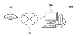
図1は、第1の実施形態に係る撮像システム100の全体図である。撮像システム100は、監視カメラ110と、クライアント装置120と、を有している。監視カメラ110とクライアント装置120は、ネットワーク130を介して相互に通信可能に接続している。監視カメラ110は、全方位ミラーまたは全周魚眼レンズを有し、全周囲の景観を撮像し、360度円環あるいは円形などの魚眼画像を撮像する。なお、監視カメラ110は、実空間が歪んだ状態で撮像される魚眼画像を撮像するものであればよく、そのための構成は実施形態に限定されるものではない。監視カメラ110は、所定の場所に設置されているものとする。監視カメラ110の設置位置としては、天井、机上、壁等が挙げられる。クライアント装置120は、監視カメラ110に対して、カメラ調整等の各種コマンドを送信する。監視カメラ110は、それらのコマンドに対するレスポンスをクライアント装置120に送信する。なお、監視カメラ110は、全周/全方位を撮像可能でなくともよく、一般的なレンズよりも広角に撮像できるカメラであればよい。魚眼画像とは、一般的なレンズよりも歪んだ状態で撮像された画像であればよい。
Hereinafter, embodiments of the present invention will be described with reference to the drawings.
(First Embodiment)
FIG. 1 is an overall view of the
図2は、撮像システム100のハードウェア構成図である。まず、監視カメラ110について説明する。監視カメラ110は、撮像装置の一例である。撮像部211は、レンズ及び撮像素子を有し、被写体の撮像及び電気信号への変換を行う。画像処理部212は、撮像部211において撮像、光電変換された信号の所定の画像処理、圧縮符号化処理を行い、魚眼画像を生成する。なお、本実施形態においては、魚眼画像は動画であるものとするが、他の例としては、静止画であってもよい。通信部217は、クライアント装置120との通信を行う。通信部217は、生成された画像データをクライアント装置120に配信する。また通信部217は、クライアント装置120から送信されるカメラ制御コマンドを受信し、システム制御部213へ伝達する。通信部217はまた、コマンドに対するレスポンスをクライアント装置120へ送信する。
FIG. 2 is a hardware configuration diagram of the
システム制御部213は、CPUを有し、監視カメラ110の全体を制御する。記憶部216は、内部ストレージ及び外部ストレージを含み、これらのストレージには撮像部211により撮像された映像が記録される。さらに、記憶部216は、ROMやRAMを有し、各種情報やプログラムを記憶している。後述する監視カメラ110の機能や処理は、システム制御部213が記憶部216に格納されているプログラムを読み出し、このプログラムを実行することにより実現されるものある。
The
システム制御部213は、例えば、伝達されたカメラ制御コマンドを解析し、コマンドに応じた処理を行う。システム制御部213はまた、画像処理部212に対して画質調整を指示する。システム制御部213はまた、レンズ制御部215に対してズームやフォーカス制御を指示する。レンズ制御部215は、伝達された指示に基づいて、レンズ駆動部214の制御を行う。レンズ駆動部214は、撮像部211のフォーカスレンズ及びズームレンズの駆動系及びその駆動源のモータを有し、その動作はレンズ制御部215により制御される。
For example, the
本実施形態においては、画像処理部212は、システム制御部213と別のハードウェアとして設けられている。他の例としては、監視カメラ110は、画像処理部212を有さず、システム制御部213が画像処理部212による処理を実行することとしてもよい。
In the present embodiment, the
次に、クライアント装置120について説明する。クライアント装置120は、情報処理装置の一例であり、例えばパーソナルコンピュータなどの汎用コンピュータが用いられる。表示部221は、例えば液晶表示装置であり、監視カメラ110から取得した画像や、カメラ制御を行うためのグラフィックユーザインターフェース(以下、GUIと称する)を表示する。入力部222は、例えばキーボードやマウス等のポインティング・デバイスである。ユーザは、入力部222を介してGUIを操作する。通信部224は、監視カメラ110との通信を行う。
Next, the
システム制御部223は、CPUを有し、クライアント装置120の全体を制御する。記憶部225は、ROMやRAM、HDD等を有し、各種情報やプログラムを記憶している。後述するクライアント装置120の機能や処理は、システム制御部223が記憶部225に格納されているプログラムを読み出し、このプログラムを実行することにより実現されるものである。システム制御部223は、例えば、ユーザのGUI操作に応じてカメラ制御コマンドを生成し、通信部224を介して監視カメラ110へ送信する。また、システム制御部223は、通信部224を介して受信した監視カメラ110からの画像データも表示部221に表示する。このようにクライアント装置120は、ネットワーク130を介して、監視カメラ110の撮像画像の取得や各種のカメラ制御を行うことができる。
The
図3は、撮像システム100の機能構成図である。監視カメラ110の画像取得部311は、画像処理部212により得られた魚眼画像を取得し、これを記憶部216に保存する。動体検出部312は、画像取得部311が取得した魚眼画像において動体を検出する。動体検出部312は、具体的には、予め背景のみが撮像された映像より背景モデルを生成しておき、これと入力映像との差分により検出する背景差分による方法で動体を検出する。なお、動体を検出するための具体的な処理はこれに限定されるものではない。他の例としては、動体検出部312は、生成された撮像映像において隣接する2フレーム間の画像の差分を求めることで、フレームから動体を検出してもよい。
FIG. 3 is a functional configuration diagram of the
切出部313は、魚眼画像の一部の領域を切り出す。具体的には、切出部313は、動体検出部312により動体が検出された領域を切り出す。補正部314は、切出部313により切り出された領域の画像に対し歪み補正を行う。補正部314は、歪み補正として、例えば切り出し画像のひずみや傾きの調整、最適なアングルへの変換等の処理を行う。サムネイル画像生成部315は、補正部314による歪み補正後の画像に基づいてサムネイル画像を生成し、これを切り出し元の魚眼画像に対応付けて記憶部216に保存する。通信制御部316は、クライアント装置120との間での情報の送受信を制御する。撮像制御部317は、通信制御部316を介してクライアント装置120から受け付けた指示に従い、撮像部211による撮像を制御する。なお、動体検出部312、切出部313、補正部314及びサムネイル画像生成部315の処理うち少なくとも1つの処理は、システム制御部213と別のハードウェアである画像処理部212により実行されることとしてもよい。
The
クライアント装置120の通信制御部321は、監視カメラ110との間での情報の送受信を制御する。表示制御部322は、表示部221への表示を制御する。受付部323は、入力部222へのユーザ操作に応じて情報を受け付ける。
The
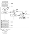
図4は、監視カメラ110による録画処理を示すフローチャートである。S400において、画像取得部311は、映像(魚眼画像)の録画を開始する。具体的には、画像取得部311は、撮像部211から魚眼画像を取得すると、これを記憶部216に保存する。次に、S401において、動体検出部312は、動体検出を開始する。動体検出部312は、映像のフレーム単位で動体検知処理を行うものとする。なお、動体検出部312は、複数フレームおきに動体検知処理を行うものとしてもよい。次に、S402において、動体検出部312は、動体を検出したか否かを確認する。動体検出部312は、動体を検出した場合には(S402でYES)、処理をS403へ進める。動体検出部312は、動体を検出しなかった場合には(S402でNO)、処理をS406へ進める。
FIG. 4 is a flowchart showing a recording process by the
S403において、切出部313は、動体が検出されたフレームにおいて、動体が検出された領域の画像を切り出す。次に、S404において、補正部314は、S403において切り出された画像に対し、歪み補正を行う。次に、S405において、サムネイル画像生成部315は、S404における歪み補正後の画像のサムネイル画像を生成する。そして、サムネイル画像生成部315は、サムネイル画像を切り出し元の魚眼画像に対応付けて記憶部216に保存する。次に、S406において、システム制御部213は、録画が終了したか否かを確認する。システム制御部213は、録画が終了していない場合には(S406でNO)、処理をS402へ進める。システム制御部213は、録画が終了した場合には(S406でYES)、録画処理を終了する。以上のようにして生成、保存されたサムネイル画像は切り出し元の魚眼画像と紐付けされ、通信制御部316によりクライアント装置120に送信される。
In S403, the
図5は、サムネイル画像を生成する処理の説明図である。図5(a)に示すように、魚眼画像のフレーム500において、動体501が検出されたとする。この場合には、動体501を含む領域502の画像が切り出される。そして、領域502の画像に対し、歪み補正が行われ、補正後の画像から図5(b)に示すようなサムネイル画像510が生成される。
FIG. 5 is an explanatory diagram of a process for generating a thumbnail image. As shown in FIG. 5A, it is assumed that the moving
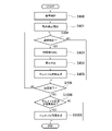
図6は、クライアント装置120による表示制御処理を示すフローチャートである。S600において、通信制御部321は、紐付けされた魚眼画像とサムネイル画像を監視カメラ110から受信し、受信した画像を記憶部225に保存する。以上の処理により、複数のサムネイル画像が記憶部225に保存されるものとする。次に、S601において、表示制御部322は、記憶部225に保存されているサムネイル画像を示す一覧画面を表示部221に表示するよう制御する。次に、S602において、受付部323は、サムネイル画像の選択指示を受け付けたか否かを確認する。一覧画面に表示された複数のサムネイル画像のうち1つのサムネイル画像をユーザが選択すると、受付部323は、選択指示を受け付ける。本処理は、受付処理の一例である。受付部323は、選択指示を受け付けると(S602でYES)、処理をS603へ進める。S603において、表示制御部322は、選択指示に係るサムネイル画像に紐付けされた魚眼画像を再生表示するよう制御する。以上で表示制御処理が完了する。
FIG. 6 is a flowchart showing a display control process by the
図7は、一覧画面700の表示例を示す図である。一覧画面700には、複数のサムネイル画像701が一覧表示されている。さらに各サムネイル画像701に対応付けて、詳細情報702が表示されている。詳細情報702は、魚眼画像に関する情報であり、例えば撮像日時、検知内容等を示す情報である。
FIG. 7 is a diagram showing a display example of the
以上のように、第1の実施形態に係るクライアント装置120は、歪み補正後の魚眼画像から生成されたサムネイル画像を表示する。すなわち、クライアント装置120は、ユーザが容易に魚眼画像の特徴を認識できるような画像を表示させる。これにより、ユーザがサムネイル画像から元の画像を認識し易くすることができる。
As described above, the
第1の実施形態の第1の変形例としては、クライアント装置120は、歪み補正後の魚眼画像に基づいて、サムネイル画像を生成すればよく、サムネイル画像の表示内容は実施形態に限定されるものではない。クライアント装置120は、例えば、魚眼画像の一部の領域ではなく、魚眼画像の全体のサムネイル画像を生成してもよい。例えば、魚眼画像において動体が検出された領域が画像全体の80%を超える場合には、魚眼画像の一部を示すサムネイル画像を表示するよりも、魚眼画像の全体を示すサムネイル画像を表示する方が好ましい。なお、この場合には、補正部314は、適宜、魚眼画像を複数の領域に分割し、各領域に対し歪み補正を施してもよい。この場合には、サムネイル画像生成部315は、例えば、歪み補正後の複数領域の画像を1つの画像に合成し、合成した画像のサムネイル画像を生成する。また、クライアント装置120は、動体以外の特徴を示す領域のサムネイル画像を表示してもよい。この場合には、監視カメラ110は、動体に替えて、クライアント装置120の表示対象となる特徴を示す領域を切り出して、サムネイル画像を生成、記録することとする。
As a first modification of the first embodiment, the
また、第2の変形例としては、クライアント装置120は、魚眼画像の一部の領域に対応したサムネイル画像上に魚眼画像の全体を示す画像を重畳してもよい。図8は、魚眼画像の全体の画像が重畳されたサムネイル画像を示す図である。図8(a)に示すサムネイル画像800は、魚眼画像の一部の領域に対応したサムネイル画像801上に、魚眼画像の全体のサムネイル画像802が重畳された画像である。図8(b)に示すサムネイル画像810は、サムネイル画像800と同様に、魚眼画像の一部の領域に対応したサムネイル画像811上に、魚眼画像の全体のサムネイル画像812が重畳された画像である。ただし、サムネイル画像810においては、サムネイル画像812には、切り出し領域の境界位置を示す枠線813が描画されている。なお、いずれの場合も、サムネイル画像801,811は、歪み補正後の画像に対応している。これにより、ユーザは、魚眼画像とサムネイル画像の位置関係を容易に把握することができる。このように、クライアント装置120が、魚眼画像の全体と特徴部分とをサムネイル画像として表示することにより、ユーザは、サムネイル画像に対応した撮像画像が魚眼画像であるか否かを容易に認識することができる。
Further, as a second modification, the
また、第3の変形例としては、クライアント装置120は、魚眼画像に対応したサムネイル画像を表示する場合に、サムネイル画像が魚眼画像に対応することを示す情報をサムネイル画像に対応付けて表示してもよい。具体的には、監視カメラ110は、魚眼画像の切り出し画像に対応したサムネイル画像に魚眼画像であることを示すマークや文字を重畳したものをサムネイル画像として生成し、これをクライアント装置120に送信することとする。これにより、クライアント装置120は、魚眼画像であることを示すマーク等が重畳されたサムネイル画像を表示することができる。また、他の例としては、クライアント装置120は、詳細情報として、魚眼画像であることを示す情報をサムネイル画像に対応付けて表示してもよい。
Further, as a third modification, when the
また、第4の変形例としては、監視カメラ110が魚眼画像を録画するタイミングは実施形態に限定されるものではない。他の例としては、監視カメラ110は、動体が検出されたタイミングから録画を開始することとしてもよい。監視カメラ110は、さらに一定時間分の魚眼画像をバッファに保持しておき、動体が検出された時点でバッファに保持された魚眼画像についても記憶部216に保存することとしてもよい。
Further, as a fourth modification, the timing at which the
また、第4の変形例としては、監視カメラ110の動体検出部312、切出部313、補正部314及びサムネイル画像生成部315の処理のうち少なくとも1つの処理を、クライアント装置120が行うこととしてもよい。例えば、クライアント装置120は、監視カメラ110から魚眼画像を取得し、動体検出、切り出し、サムネイル生成を行い、サムネイルを一覧表示するよう制御してもよい。
Further, as a fourth modification, the
(第2の実施形態)
第2の実施形態に係る撮像システム100は、動体の検出結果から、置き去り等のイベントを検出し、イベントの検出結果に応じたサムネイル画像を生成、表示する。以下、第2の実施形態に係る撮像システム100について、第1の実施形態に係る撮像システム100と異なる点を説明する。監視カメラ110の動体検出部312は、動体検出だけでなく、置き去りや、監視カメラ110に対するいたずらなど複数のイベントの検出も行う。動体検出部312は、例えば、動体が一定時間所定の場所に置かれた状態が継続した場合に、置き去りのイベントを検出する。イベントの種類によっては、必ずしもイベントの検出タイミングに撮像された画像(フレーム)がその撮像画像(映像)の特徴を表す静止画とは限らない。例えば、置き去り検出においては、物体が置き去られたタイミング(つまり置き去りを検出したタイミングが重要であり、このタイミングの静止画を、特徴を表す画像とするのが望ましい。また、いたずら検出においても、いたずらを検出した時点よりも前の時点の静止画の方が特徴を表している場合がある。第2の実施形態に係る監視カメラ110は、このようなイベントの検出結果に応じて、サムネイル画像を生成する。
(Second embodiment)
The
図9は、監視カメラ110による録画処理を示すフローチャートである。S900において、画像取得部311は、映像(魚眼画像)の録画を開始する。次に、S901において、動体検出部312は、動体検出を開始する。なお、S900及びS901の処理は、それぞれ図4を参照しつつ説明したS400及びS401の処理と同様である。次に、S902において、動体検出部312は、動体検出の結果に基づいて、イベントを検出したか否かを確認する。動体検出部312は、置き去りを検出した場合には(S902でYES)、処理をS903へ進める。動体検出部312は、いたずらを検出した場合には(S902でNO、S904でYES)、処理をS905へ進める。動体検出部312は、置き去り及びいたずら以外のその他のイベントを検出した場合には(S906でYES)、処理をS907へ進める。動体検出部312は、いずれのイベントも検出しなかった場合には(S902でNO、S904でNO、S906でNO)、処理をS908へ進める。
FIG. 9 is a flowchart showing the recording process by the
S903において、切出部313は、置き去りを検出したタイミングから第1時間前のフレームを、切り出しの対象として選択し、その後処理をS908へ進める。ここで、第1時間は、予め設定された値とする。第1時間は、例えば、動体検出から置き去りと判断するまでに必要な、置き去りの状態の継続時間(例えば10秒等)と等しい値である。S905において、切出部313は、いたずらを検出したタイミングから第2時間前のフレームを、切り出しの対象として選択し、その後処理をS908へ進める。ここで、第2時間は、予め設定された値とする。第2時間は、例えば、動体検出から、いたずらと判断するまでに必要な時間(例えば2秒等)と等しい値である。S907において、切出部313は、イベントを検出したタイミングのフレームを切り出しの対象として選択し、その後処理をS908へ進める。S908において、切出部313は、S903、S905又はS907において選択されたフレームを処理対象として画像の切り出しを行う。続く、S909~S912の処理は、S404~S407(図4)の処理と同様である。なお、第2の実施形態に係る撮像システム100のこれ以外の構成及び処理は、第1の実施形態に係る撮像システム100の構成及び処理と同様である。
In S903, the
以上のように、第2の実施形態に係る監視カメラ110は、イベントを検出した場合に、イベントの種類に応じて、サムネイル画像として用いるフレームを適切に選択することで、イベントに特徴的なサムネイル画像を生成することができる。また、クライアント装置120は、イベントに対応した適切なサムネイル画像を表示することができる。
As described above, when the
なお、変形例としては、イベントが検出された撮像画像のサムネイル画像は、イベントに特徴的なフレームであればよく、実施形態に限定されるものではない。他の例としては、サムネイル画像は、第1時間や第2時間のように所定時間前のフレーム全体から生成されるサムネイル画像であってもよい。また、他の例としては、監視カメラ110は、イベントが検出される直前のフレームのうち、検出対象の動体にフォーカスが合っているフレームを用いてサムネイル画像を生成してもよい。
As a modification, the thumbnail image of the captured image in which the event is detected may be a frame characteristic of the event, and is not limited to the embodiment. As another example, the thumbnail image may be a thumbnail image generated from the entire frame before a predetermined time, such as the first time or the second time. As another example, the
(第3の実施形態)
第3の実施形態に係る撮像システム100は、1つの魚眼画像から複数のサムネイル画像が生成された場合に、複数のサムネイル画像からサムネイル表示用の動画(サムネイル動画)を生成し、これを表示する。以下、第3の実施形態に係る撮像システム100について、他の実施形態に係る撮像システム100と異なる点を説明する。
(Third embodiment)
When a plurality of thumbnail images are generated from one fisheye image, the
図10は、第3の実施形態に係る監視カメラ110による録画処理を示すフローチャートである。なお、図10に示す録画処理の各処理のうち、図4を参照しつつ説明した第1の実施形態に係る録画処理の各処理と同一の処理には、同一の番号を付している。第3の実施形態においては、監視カメラ110のシステム制御部213は、S406において、録画が終了した場合に(S406でYES)、処理をS1000へ進める。S1000において、サムネイル画像生成部315は、1つの魚眼画像から複数のサムネイル画像を生成したか否かを確認する。サムネイル画像生成部315は、複数のサムネイル画像を生成した場合には(S1000でYES)、処理をS1001へ進める。サムネイル画像生成部315は、複数のサムネイル画像を生成しなかった場合、すなわちサムネイル画像が1枚又は0枚の場合には(S1000でNO)、録画処理を終了する。
FIG. 10 is a flowchart showing a recording process by the
S1001において、サムネイル画像生成部315は、1つの魚眼画像から生成された複数のサムネイル画像を合成することにより、1つのサムネイル動画を生成する。そして、サムネイル画像生成部315は、サムネイル動画を魚眼画像に対応付けて記憶部216に保存する。以上で、録画処理が完了する。これに対応し、クライアント装置120は、一覧画面において、サムネイル動画を再生表示する。なお、第3の実施形態に係る撮像システム100のこれ以外の構成及び処理は、他の実施形態に係る撮像システム100の構成及び処理と同様である。
In S1001, the thumbnail
以上のように、第3の実施形態に係る監視カメラ110は、複数のサムネイル画像を合成したサムネイル動画を生成する。そして、クライアント装置120は、サムネイル動画を再生表示する。これにより、ユーザは、魚眼画像を再生表示させる前に、対応するサムネイル動画の再生表示を見ることで、その魚眼画像の内容を確認することができる。
As described above, the
(第4の実施形態)
第4の実施形態に係る撮像システム100は、魚眼画像から切り出された一部の領域を示すサムネイル画像と、魚眼画像の全体を示すサムネイル画像とを合成してサムネイル動画を生成し、これを表示する。以下、第4の実施形態に係る撮像システム100について、他の実施形態に係る撮像システム100と異なる点を説明する。
(Fourth Embodiment)
The
図11は、第4の実施形態に係る撮像システム100による録画処理を示すフローチャートである。なお、図11に示す録画処理の各処理のうち、図4を参照しつつ説明した第1の実施形態に係る録画処理の各処理と同一の処理には、同一の番号を付している。第4の実施形態においては、監視カメラ110のシステム制御部213は、S404の処理の後、処理をS1100へ進める。S1100において、サムネイル画像生成部315は、動体が検出されたフレームから切り出され、歪み補正が施された画像のサムネイル画像を生成する。サムネイル画像生成部315はまた、動体が検出されたフレームの全体を示すサムネイル画像を生成する。そして、サムネイル画像生成部315は、フレームから切り出された画像のサムネイル画像と、フレームの全体を示すサムネイル画像とを合成することにより、1つのサムネイル動画を生成する。そして、サムネイル画像生成部315は、サムネイル動画を魚眼画像に対応付けて記憶部216に保存する。以上で、録画処理が完了する。これに対応し、クライアント装置120は、一覧画面において、サムネイル動画を再生表示する。なお、第4の実施形態に係る撮像システム100のこれ以外の構成及び処理は、他の実施形態に係る撮像システム100の構成及び処理と同様である。
FIG. 11 is a flowchart showing a recording process by the
以上のように、第4の実施形態に係る監視カメラ110は、魚眼画像から切り出された一部の領域を示すサムネイル画像と、魚眼画像の全体を示すサムネイル画像とを合成してサムネイル動画を生成する。そして、クライアント装置120は、サムネイル動画を再生表示する。これにより、ユーザは、魚眼画像を再生表示させる前に、対応するサムネイルと魚眼画像の全体を示すサムネイルの動画の再生表示を見ることで、その魚眼画像の内容を確認することができる。
As described above, the
以上、本発明の好ましい実施形態について詳述したが、本発明は係る特定の実施形態に限定されるものではなく、特許請求の範囲に記載された本発明の要旨の範囲内において、種々の変形・変更が可能である。 Although the preferred embodiments of the present invention have been described in detail above, the present invention is not limited to the specific embodiment, and various modifications are made within the scope of the gist of the present invention described in the claims.・ Can be changed.
(その他の実施例)
本発明は、上述の実施形態の1以上の機能を実現するプログラムを、ネットワーク又は記憶媒体を介してシステム又は装置に供給し、そのシステム又は装置のコンピュータにおける1つ以上のプロセッサーがプログラムを読出し実行する処理でも実現可能である。また、1以上の機能を実現する回路(例えば、ASIC)によっても実現可能である。
(Other examples)
The present invention supplies a program that realizes one or more functions of the above-described embodiment to a system or device via a network or storage medium, and one or more processors in the computer of the system or device reads and executes the program. It can also be realized by the processing to be performed. It can also be realized by a circuit (for example, ASIC) that realizes one or more functions.
100 撮像システム
110 撮像装置
120 クライアント装置
100
Claims (13)
前記魚眼画像全体の前記サムネイル画像、または、前記部分画像の前記サムネイル画像の選択指示を受け付ける受付手段と
を有し、
前記表示制御手段は、前記受付手段が前記魚眼画像全体の前記サムネイル画像の前記選択指示、または、前記部分画像の前記サムネイル画像の前記選択指示を受け取った場合、前記選択指示に応じた前記サムネイル画像に対応する前記魚眼画像を前記表示手段に表示させることを特徴とする情報処理装置。 One of the thumbnail image of the entire fisheye image captured by the fisheye lens based on the detection state of the moving object and the thumbnail image of the partial image corresponding to a part of the fisheye image is used as the display means. Display control means to display and
It has a receiving means for receiving a selection instruction of the thumbnail image of the entire fish-eye image or the thumbnail image of the partial image .
When the reception means receives the selection instruction of the thumbnail image of the entire fish-eye image or the selection instruction of the thumbnail image of the partial image, the display control means responds to the selection instruction. An information processing apparatus characterized in that the fish-eye image corresponding to an image is displayed on the display means.
前記表示制御手段は、前記魚眼画像に含まれる1つのフレームのサムネイル画像を表示手段に表示させることを特徴とする請求項1又は2に記載の情報処理装置。 The fisheye image is a moving image,
The information processing apparatus according to claim 1 or 2, wherein the display control means causes the display means to display a thumbnail image of one frame included in the fisheye image.
動体の検出状態に基づいて、前記歪み補正が施された前記部分画像のサムネイル画像、および、魚眼レンズを用いて撮像された魚眼画像全体のサムネイル画像のうちいずれか一方を生成する生成手段と、
前記部分画像の前記サムネイル画像と前記魚眼画像全体の前記サムネイル画像のそれぞれについて、対応する前記魚眼画像に対応付けて記憶手段に保存する保存手段と
を有することを特徴とする撮像装置。 A correction means for correcting distortion of a partial image corresponding to a part of a region of a fisheye image captured by a fisheye lens, and a correction means.
A generation means for generating either a thumbnail image of the partial image to which the distortion has been corrected or a thumbnail image of the entire fisheye image captured by the fisheye lens based on the detection state of the moving object .
An image pickup apparatus comprising: each of the thumbnail image of the partial image and the thumbnail image of the entire fisheye image are stored in a storage means in association with the corresponding fisheye image.
前記魚眼画像全体の前記サムネイル画像、または、前記部分画像の前記サムネイル画像の選択指示を受け付ける受付ステップと
を含み、
前記表示制御ステップにおいては、前記受付ステップにおいて、前記魚眼画像全体の前記サムネイル画像の前記選択指示、または、前記部分画像の前記サムネイル画像の前記選択指示を受け取った場合、前記選択指示に応じた前記サムネイル画像に対応する前記魚眼画像を前記表示手段に表示させることを特徴とする情報処理方法。 One of the thumbnail image of the entire fisheye image captured by the fisheye lens based on the detection state of the moving object and the thumbnail image of the partial image corresponding to a part of the fisheye image is used as the display means. Display control steps to be displayed and
The reception step for receiving the selection instruction of the thumbnail image of the whole fisheye image or the thumbnail image of the partial image is included.
In the display control step, when the selection instruction of the thumbnail image of the entire fish-eye image or the selection instruction of the thumbnail image of the partial image is received in the reception step, the selection instruction is responded to. An information processing method characterized in that the fisheye image corresponding to the thumbnail image is displayed on the display means.
Priority Applications (4)
| Application Number | Priority Date | Filing Date | Title |
|---|---|---|---|
| JP2017182620A JP7086552B2 (en) | 2017-09-22 | 2017-09-22 | Information processing equipment, imaging equipment, information processing methods and programs |
| US16/134,674 US20190098250A1 (en) | 2017-09-22 | 2018-09-18 | Information processing apparatus, imaging apparatus, information processing method, and recording medium |
| CN201811099802.7A CN109547743A (en) | 2017-09-22 | 2018-09-20 | Information processing unit, photographic device, information processing method and recording medium |
| EP18195999.0A EP3460674A1 (en) | 2017-09-22 | 2018-09-21 | Appartus, method and program for displaying thumbnails of fisheye images |
Applications Claiming Priority (1)
| Application Number | Priority Date | Filing Date | Title |
|---|---|---|---|
| JP2017182620A JP7086552B2 (en) | 2017-09-22 | 2017-09-22 | Information processing equipment, imaging equipment, information processing methods and programs |
Publications (3)
| Publication Number | Publication Date |
|---|---|
| JP2019057891A JP2019057891A (en) | 2019-04-11 |
| JP2019057891A5 JP2019057891A5 (en) | 2020-11-05 |
| JP7086552B2 true JP7086552B2 (en) | 2022-06-20 |
Family
ID=63833770
Family Applications (1)
| Application Number | Title | Priority Date | Filing Date |
|---|---|---|---|
| JP2017182620A Active JP7086552B2 (en) | 2017-09-22 | 2017-09-22 | Information processing equipment, imaging equipment, information processing methods and programs |
Country Status (4)
| Country | Link |
|---|---|
| US (1) | US20190098250A1 (en) |
| EP (1) | EP3460674A1 (en) |
| JP (1) | JP7086552B2 (en) |
| CN (1) | CN109547743A (en) |
Families Citing this family (5)
| Publication number | Priority date | Publication date | Assignee | Title |
|---|---|---|---|---|
| US20190088108A1 (en) * | 2017-09-18 | 2019-03-21 | Qualcomm Incorporated | Camera tampering detection |
| JP7268369B2 (en) * | 2019-01-30 | 2023-05-08 | 株式会社リコー | Imaging system, development system, imaging method, and program |
| WO2021077279A1 (en) * | 2019-10-22 | 2021-04-29 | 深圳市大疆创新科技有限公司 | Image processing method and device, and imaging system and storage medium |
| CN113496458A (en) * | 2020-03-18 | 2021-10-12 | 杭州海康威视数字技术股份有限公司 | Image processing method, device, equipment and storage medium |
| CN111565300B (en) * | 2020-05-22 | 2020-12-22 | 深圳市百川安防科技有限公司 | Object-based video file processing method, device and system |
Citations (11)
| Publication number | Priority date | Publication date | Assignee | Title |
|---|---|---|---|---|
| JP2000224542A (en) | 1999-01-29 | 2000-08-11 | Hitachi Ltd | Image storage device, monitor system and storage medium |
| US20100002071A1 (en) | 2004-04-30 | 2010-01-07 | Grandeye Ltd. | Multiple View and Multiple Object Processing in Wide-Angle Video Camera |
| JP2013080998A (en) | 2011-09-30 | 2013-05-02 | Dainippon Printing Co Ltd | Image processing device, image processing method, and image processing program |
| JP2013179498A (en) | 2012-02-28 | 2013-09-09 | Glory Ltd | Image processing method and image processing device |
| JP2016158021A (en) | 2015-02-23 | 2016-09-01 | キヤノン株式会社 | Image processing system and image processing method |
| JP2017063402A (en) | 2015-09-25 | 2017-03-30 | ソニー株式会社 | Representative image generating apparatus, representative image generating method, and program |
| WO2017056942A1 (en) | 2015-09-30 | 2017-04-06 | 富士フイルム株式会社 | Image processing device, imaging device, image processing method, and program |
| JP2017118472A (en) | 2015-12-22 | 2017-06-29 | カシオ計算機株式会社 | Image processing device, image processing method and program |
| US20170244959A1 (en) | 2016-02-19 | 2017-08-24 | Adobe Systems Incorporated | Selecting a View of a Multi-View Video |
| WO2017146012A1 (en) | 2016-02-24 | 2017-08-31 | コニカミノルタ株式会社 | Monitored-person monitoring device, method and system |
| JP2017152804A (en) | 2016-02-22 | 2017-08-31 | 株式会社キーエンス | Safety scanner, optical safety system and setting support device for safety scanner |
Family Cites Families (2)
| Publication number | Priority date | Publication date | Assignee | Title |
|---|---|---|---|---|
| JP2015038640A (en) * | 2010-04-19 | 2015-02-26 | 株式会社東芝 | Video display device and video display method |
| FR3041134B1 (en) * | 2015-09-10 | 2017-09-29 | Parrot | DRONE WITH FRONTAL VIEW CAMERA WHOSE PARAMETERS OF CONTROL, IN PARTICULAR SELF-EXPOSURE, ARE MADE INDEPENDENT OF THE ATTITUDE. |
-
2017
- 2017-09-22 JP JP2017182620A patent/JP7086552B2/en active Active
-
2018
- 2018-09-18 US US16/134,674 patent/US20190098250A1/en not_active Abandoned
- 2018-09-20 CN CN201811099802.7A patent/CN109547743A/en active Pending
- 2018-09-21 EP EP18195999.0A patent/EP3460674A1/en not_active Withdrawn
Patent Citations (11)
| Publication number | Priority date | Publication date | Assignee | Title |
|---|---|---|---|---|
| JP2000224542A (en) | 1999-01-29 | 2000-08-11 | Hitachi Ltd | Image storage device, monitor system and storage medium |
| US20100002071A1 (en) | 2004-04-30 | 2010-01-07 | Grandeye Ltd. | Multiple View and Multiple Object Processing in Wide-Angle Video Camera |
| JP2013080998A (en) | 2011-09-30 | 2013-05-02 | Dainippon Printing Co Ltd | Image processing device, image processing method, and image processing program |
| JP2013179498A (en) | 2012-02-28 | 2013-09-09 | Glory Ltd | Image processing method and image processing device |
| JP2016158021A (en) | 2015-02-23 | 2016-09-01 | キヤノン株式会社 | Image processing system and image processing method |
| JP2017063402A (en) | 2015-09-25 | 2017-03-30 | ソニー株式会社 | Representative image generating apparatus, representative image generating method, and program |
| WO2017056942A1 (en) | 2015-09-30 | 2017-04-06 | 富士フイルム株式会社 | Image processing device, imaging device, image processing method, and program |
| JP2017118472A (en) | 2015-12-22 | 2017-06-29 | カシオ計算機株式会社 | Image processing device, image processing method and program |
| US20170244959A1 (en) | 2016-02-19 | 2017-08-24 | Adobe Systems Incorporated | Selecting a View of a Multi-View Video |
| JP2017152804A (en) | 2016-02-22 | 2017-08-31 | 株式会社キーエンス | Safety scanner, optical safety system and setting support device for safety scanner |
| WO2017146012A1 (en) | 2016-02-24 | 2017-08-31 | コニカミノルタ株式会社 | Monitored-person monitoring device, method and system |
Also Published As
| Publication number | Publication date |
|---|---|
| CN109547743A (en) | 2019-03-29 |
| US20190098250A1 (en) | 2019-03-28 |
| EP3460674A1 (en) | 2019-03-27 |
| JP2019057891A (en) | 2019-04-11 |
Similar Documents
| Publication | Publication Date | Title |
|---|---|---|
| JP7086552B2 (en) | Information processing equipment, imaging equipment, information processing methods and programs | |
| JPWO2004066632A1 (en) | Remote video display method, video acquisition device, method and program thereof | |
| US20170061686A1 (en) | Stage view presentation method and system | |
| JPWO2008114499A1 (en) | Imaging apparatus and imaging method | |
| GB2485036A (en) | Preventing subject occlusion in a dual lens camera PIP display | |
| JP2007295335A (en) | Camera device and image recording and reproducing method | |
| JP6497965B2 (en) | Image processing apparatus and image processing method | |
| JP2013027021A (en) | Omnidirectional imaging device and omnidirectional imaging method | |
| JP4924228B2 (en) | Image processing apparatus, image processing method, and program | |
| KR20180129667A (en) | Display control apparatus, display control method, and storage medium | |
| JP2017175319A (en) | Image processing apparatus, image processing method, and program | |
| JP2012119804A (en) | Image recorder | |
| US9137448B2 (en) | Multi-recording image capturing apparatus and control method for multi-recording image capturing apparatus for enabling the capture of two image areas having two different angles of view | |
| JP6312426B2 (en) | Imaging apparatus and control method thereof | |
| JP6261191B2 (en) | Display control apparatus, display control method, and program | |
| US20230217084A1 (en) | Image capture apparatus, control method therefor, image processing apparatus, and image processing system | |
| JP2009088850A (en) | Moving image distribution system and moving image distributing method | |
| JP2010263269A (en) | Imaging apparatus | |
| JP2004248171A (en) | Moving image recorder, moving image reproduction device, and moving image recording and reproducing device | |
| JP2019032448A (en) | Control unit, control method, and program | |
| US11825191B2 (en) | Method for assisting the acquisition of media content at a scene | |
| JP4857297B2 (en) | Video processing device | |
| JP4172352B2 (en) | Imaging apparatus and method, imaging system, and program | |
| JP2017063276A (en) | Video display device, video display method and program | |
| JP2013084124A (en) | Imaging system, imaging device, and image processing method |
Legal Events
| Date | Code | Title | Description |
|---|---|---|---|
| A521 | Request for written amendment filed |
Free format text: JAPANESE INTERMEDIATE CODE: A523 Effective date: 20200914 |
|
| A621 | Written request for application examination |
Free format text: JAPANESE INTERMEDIATE CODE: A621 Effective date: 20200914 |
|
| A977 | Report on retrieval |
Free format text: JAPANESE INTERMEDIATE CODE: A971007 Effective date: 20210907 |
|
| A131 | Notification of reasons for refusal |
Free format text: JAPANESE INTERMEDIATE CODE: A131 Effective date: 20211026 |
|
| A521 | Request for written amendment filed |
Free format text: JAPANESE INTERMEDIATE CODE: A523 Effective date: 20211210 |
|
| TRDD | Decision of grant or rejection written | ||
| A01 | Written decision to grant a patent or to grant a registration (utility model) |
Free format text: JAPANESE INTERMEDIATE CODE: A01 Effective date: 20220510 |
|
| A61 | First payment of annual fees (during grant procedure) |
Free format text: JAPANESE INTERMEDIATE CODE: A61 Effective date: 20220608 |
|
| R151 | Written notification of patent or utility model registration |
Ref document number: 7086552 Country of ref document: JP Free format text: JAPANESE INTERMEDIATE CODE: R151 |