JP7069002B2 - Field work vehicle and field map data generation system - Google Patents
Field work vehicle and field map data generation system Download PDFInfo
- Publication number
- JP7069002B2 JP7069002B2 JP2018239576A JP2018239576A JP7069002B2 JP 7069002 B2 JP7069002 B2 JP 7069002B2 JP 2018239576 A JP2018239576 A JP 2018239576A JP 2018239576 A JP2018239576 A JP 2018239576A JP 7069002 B2 JP7069002 B2 JP 7069002B2
- Authority
- JP
- Japan
- Prior art keywords
- field
- shore
- work
- position coordinates
- vehicle body
- Prior art date
- Legal status (The legal status is an assumption and is not a legal conclusion. Google has not performed a legal analysis and makes no representation as to the accuracy of the status listed.)
- Active
Links
Images


Landscapes
- Guiding Agricultural Machines (AREA)
- Instructional Devices (AREA)
Description
本発明は、圃場の畔によって境界付けられた圃場面の外形を示す圃場面地図データを生成する地図データ生成機能を有する圃場作業車、及びそのような地図データ生成機能を有する圃場地図データ生成システムに関する。 The present invention is a field work vehicle having a map data generation function for generating field scene map data indicating the outline of a field scene bounded by the shore of the field, and a field map data generation system having such a map data generation function. Regarding.
圃場作業車が、衛星測位技術を用いて圃場を自動走行するために、走行目標となる走行経路を生成する必要がある。圃場を網羅する走行経路を生成するためには、圃場の形状を正確に示す地図データが必要である。圃場は、私的な農道や畔などを境界線として区画されているので、一般的な地図データから正確な圃場の形状を得ることは困難である。 In order for a field work vehicle to automatically travel in a field using satellite positioning technology, it is necessary to generate a travel route that is a travel target. In order to generate a traveling route that covers the field, map data that accurately shows the shape of the field is required. Since the fields are divided by private farm roads and shores as boundaries, it is difficult to obtain an accurate field shape from general map data.
特許文献1には、圃場面の周囲を手動で走行する外形ティーチング走行を通じて圃場面の外形データを取得するトラクタが開示されている。このトラクタはGPS測位機能を有し、トラクタの左右前後の外端部の位置座標が算出可能である。外形ティーチング走行では、多角形状の圃場面の各形状特徴点(多角形の頂点)にトラクタが移動する毎に、その地点のGPS位置座標を取得する。圃場面の全ての形状特徴点の位置座標が取得されると、圃場面の形状が算出される。その際、トラクタが圃場面に出入するための出入口の両側の端点の位置座標も取得され、当該出入口の位置も圃場面の外形データに登録される。算出された圃場面の外形データに基づいて作業対象領域が設定され、トラクタが当該作業対象領域を自動走行するための走行経路が生成される。 Patent Document 1 discloses a tractor that acquires external shape data of a field scene through external teaching running that manually travels around the field scene. This tractor has a GPS positioning function, and the position coordinates of the left, right, front, rear, and outer ends of the tractor can be calculated. In the external teaching run, each time the tractor moves to each shape feature point (polygon apex) of the polygonal field scene, the GPS position coordinates of that point are acquired. When the position coordinates of all the shape feature points of the field scene are acquired, the shape of the field scene is calculated. At that time, the position coordinates of the end points on both sides of the doorway for the tractor to enter and exit the field scene are also acquired, and the position of the doorway is also registered in the external shape data of the field scene. A work target area is set based on the calculated external shape data of the field scene, and a travel route for the tractor to automatically travel in the work target area is generated.
特許文献1では、トラクタが圃場面の各コーナまで走行する毎に、圃場面の境界に近いトラクタのエッジ部の位置座標を取得し、これらの位置座標に基づいて圃場面の外形データが生成される。このため、一般的な地図データから圃場面の外形データを求めるよりは、正確な外形データが得られる。しかしながら、トラクタの操縦性や圃場面の状態を考えるとは、トラクタの特定部位が圃場面の境界に正確に近接することは困難である。このため、さらに正確な圃場面地図データを生成するための、新しい技術が要望されている。 In Patent Document 1, each time the tractor travels to each corner of the field scene, the position coordinates of the edge portion of the tractor near the boundary of the field scene are acquired, and the outline data of the field scene is generated based on these position coordinates. To. Therefore, more accurate outer shape data can be obtained than to obtain the outer shape data of the field scene from general map data. However, considering the maneuverability of the tractor and the state of the field scene, it is difficult for a specific part of the tractor to be accurately close to the boundary of the field scene. Therefore, a new technique for generating more accurate field map data is required.
本発明による圃場作業車は、走行車体と、圃場の畔に対する作業を行うために前記走行車体に装備された畔作業装置と、測位データに基づいて算出された車体基準位置と、当該車体基準位置と前記畔作業装置と当該畔作業装置の前記畔に対する作業箇所との位置関係から前記作業箇所の位置座標を算出し、算出された前記作業箇所の位置座標に基づいて、前記畔と圃場面との間の境界線上の境界点の位置座標を算出する境界位置算出部と、前記境界位置算出部によって経時的に算出された前記境界点の位置座標に基づいて、前記圃場面の外形を示す圃場面地図データを生成する地図データ生成部とを備えている。 The field work vehicle according to the present invention includes a traveling vehicle body, a shore work device equipped on the traveling vehicle body for performing work on the shore of the field, a vehicle body reference position calculated based on positioning data, and the vehicle body reference position. And the position coordinates of the work place are calculated from the positional relationship between the shore work device and the work place with respect to the shore of the shore work device, and based on the calculated position coordinates of the work place, the shore and the field scene. The outline of the farm scene is shown based on the boundary position calculation unit that calculates the position coordinates of the boundary point on the boundary line between the two and the position coordinates of the boundary point calculated over time by the boundary position calculation unit. It is equipped with a map data generation unit that generates field scene map data.
この構成では、圃場面の外形境界線を作り出す畔に対して作業を行う畔作業装置の作業箇所が測定点となり、この測定点の位置座標に基づいて圃場面地図データが生成される。作業箇所である測定点の位置座標は、圃場面の境界線上の位置座標、つまり圃場面の外形線上の点の位置座標とほぼ一致する。圃場が農道に隣接している場合、圃場面の一辺が農道によって境界付けられているが、その他の圃場面の辺は畔によって境界付けられている。このことから、本発明によって生成される圃場面地図データは従来に比べて、実質的に高い精度を有する。 In this configuration, the work point of the shore work device that performs work on the shore that creates the outer boundary line of the field scene becomes the measurement point, and the field scene map data is generated based on the position coordinates of the measurement point. The position coordinates of the measurement point, which is the work place, substantially match the position coordinates on the boundary line of the field scene, that is, the position coordinates of the points on the outline line of the field scene. When the field is adjacent to the farm road, one side of the field scene is bounded by the farm road, while the other side of the field scene is bounded by the shore. From this, the field map data generated by the present invention has substantially higher accuracy than the conventional one.
圃場面の一辺が農道の土手等の境界物によって境界付けられている場合、その一辺には畔が存在しないので、その圃場面の一辺に対応する畔作業装置の作業箇所(測定点)の位置座標は得られない。この場合、走行車体が境界物にできるだけ接近し、境界物に沿って走行することで、畔作業装置の動作停止中であっても、境界物と圃場面との間の境界線上の境界点に近似する測定点の位置座標は算出することができる。したがって、本発明の好適な実施形態の圃場作業車は、前記畔が欠損している欠損領域での前記境界点の位置座標は、前記走行車体の非畔作業状態での前記欠損領域に沿った走行によって得られる前記測位データに基づいて算出されるように構成されている。 When one side of the field scene is bounded by a boundary object such as a bank of a farm road, there is no shore on that side, so the position of the work location (measurement point) of the shore work device corresponding to one side of the field scene. No coordinates are available. In this case, the traveling vehicle body approaches the boundary object as close as possible and travels along the boundary object so that the traveling vehicle body reaches the boundary point on the boundary line between the boundary object and the field scene even when the operation of the shore work device is stopped. The position coordinates of the approximate measurement points can be calculated. Therefore, in the field work vehicle of the preferred embodiment of the present invention, the position coordinates of the boundary point in the defective region where the shore is defective are along the defective region in the non-shore working state of the traveling vehicle body. It is configured to be calculated based on the positioning data obtained by traveling.
同様に、圃場面への進入及び圃場面からの退出のための圃場出入口の領域も、畔が存在しない。したがって、圃場出入口の領域でも、畔作業装置を利用した位置座標の算出が不可能である。圃場出入り口を通過する際には、ほとんどの場合、畔作業装置への動力伝達は遮断され、畔作業装置は非作業姿勢に退避している。したがって、畔作業装置の作業状態から、走行車体の圃場出入口の通過が検知可能であるので、走行車体の圃場出入口の通過の前後の走行車体または畔作業装置の位置座標から、圃場出入口の位置座標を決定することが可能である。このことを実現するため、本発明の好適な実施形態の1つでは、前記畔作業装置の状態を示す信号に基づいて、前記圃場面への進入及び前記圃場面からの退出のための圃場出入口の位置座標を決定する出入口決定部が備えられている。 Similarly, the area of the field entrance / exit for entering and exiting the field scene does not have a shore. Therefore, it is impossible to calculate the position coordinates using the shore work device even in the area of the field entrance / exit. When passing through the field entrance, in most cases, the power transmission to the shore work equipment is cut off, and the shore work equipment is evacuated to the non-working posture. Therefore, since it is possible to detect the passage of the traveling vehicle body through the field entrance / exit from the working state of the shore work device, the position coordinates of the field entrance / exit from the position coordinates of the traveling vehicle body or the shore work device before and after the passage of the traveling vehicle body through the field entrance / exit. It is possible to determine. In order to realize this, in one of the preferred embodiments of the present invention, a field entrance / exit for entering and exiting the field scene is based on a signal indicating the state of the shore work device. It is equipped with an entrance / exit determination unit that determines the position coordinates of.
圃場作業車が圃場出入口を通って圃場から出る場合、圃場出入口は狭く、かつ傾斜面となっているので、その走行には細心の注意が必要であり、圃場作業車に対しても種々の制限条件(片ブレーキの禁止、搭載作業装置の安定姿勢維持、低車速の維持、大きな操舵角の禁止など)が課せられる。したがって、出入口決定部によって決定されている圃場出入口の位置座標を圃場作業車が通過する際には、運転者にそのような制限条件が守られているかどうか確認させることが好ましい。このことから、本発明の好適な実施形態の1つでは、前記測位データに基づいて算出された前記走行車体の位置座標と前記圃場出入口の位置座標とに基づいて、前記走行車体の前記圃場出入口の通過を認識する出入口通過認識部が備えられ、前記走行車体の前記圃場出入口の通過が報知される。 When a field work vehicle exits the field through a field entrance / exit, the field entrance / exit is narrow and has a sloping surface, so great care must be taken when traveling, and there are various restrictions on the field work vehicle. Conditions (prohibition of one-sided braking, maintenance of stable posture of mounted work equipment, maintenance of low vehicle speed, prohibition of large steering angle, etc.) are imposed. Therefore, when the field work vehicle passes the position coordinates of the field entrance / exit determined by the entrance / exit determination unit, it is preferable to have the driver confirm whether such a restriction condition is observed. From this, in one of the preferred embodiments of the present invention, the field entrance / exit of the traveling vehicle body is based on the position coordinates of the traveling vehicle body and the position coordinates of the field entrance / exit calculated based on the positioning data. An entrance / exit passage recognition unit for recognizing the passage of the vehicle is provided, and the passage of the traveling vehicle body through the field entrance / exit is notified.
走行とともに直線状の畔を形成する畔作業装置を装備した圃場作業車は、正確な直線走行軌跡となるように走行することが重要である。このような走行は、直線距離が長い場合、熟練していない運転者にとっては、困難である。この問題を解消するため、本発明の好適な実施形態の1つでは、所定距離の手動走行で取得された前記測位データに基づいて算出された基準走行方位を目標走行方位として、前記走行車体を自動操舵する方位維持制御部が備えられている。この構成では、畔作業装置を用いて畔を形成しながら所定距離だけ手動での直進走行が行われると、その手動走行で得られた基準走行方位を自動操舵の目標走行方位とする自動走行が可能となる。運転者は、所定距離(数m)だけ慎重に直線走行を行えば、そのあとは、自動走行に切り替えることができる。自動走行に切り替えられると、運転者は、操舵から開放され、他の操作や形成された畔のチェックを行うことができる。 It is important that the field work vehicle equipped with the shore work device that forms a straight shore with the running travels so as to have an accurate straight shore. Such traveling is difficult for an unskilled driver when the straight line distance is long. In order to solve this problem, in one of the preferred embodiments of the present invention, the traveling vehicle body is set as a target traveling direction with a reference traveling direction calculated based on the positioning data acquired by manual traveling of a predetermined distance as a target traveling direction. It is equipped with an azimuth maintenance control unit that automatically steers. In this configuration, when the vehicle is manually driven straight for a predetermined distance while forming a shore using a shore work device, automatic driving is performed in which the reference driving direction obtained by the manual driving is set as the target driving direction for automatic steering. It will be possible. The driver can carefully drive in a straight line for a predetermined distance (several meters) and then switch to automatic driving. When switched to autonomous driving, the driver is released from steering and can perform other operations and check the formed shores.
畔の高さや畔周辺の圃場面の起伏状態などは、水田形成にとって重要なデータであるので、これらのデータを管理することは、水田営農において重要である。このことから、本発明の好適な実施形態の1つでは、前記畔作業装置は、昇降機構を介して前記走行車体に装備されており、前記昇降機構の昇降量、前記走行車体の傾斜度、前記測位データに含まれている高さデータのうちの少なくとも1つを用いて、前記圃場面の起伏状態を示す起伏データを生成する起伏データ生成部が備えられている。 Since the height of the shore and the undulation state of the field scene around the shore are important data for paddy field formation, it is important to manage these data in paddy field farming. From this, in one of the preferred embodiments of the present invention, the shore work device is mounted on the traveling vehicle body via an elevating mechanism, and the elevating amount of the elevating mechanism, the inclination degree of the traveling vehicle body, and the like. An undulation data generation unit that generates undulation data indicating the undulation state of the field scene is provided by using at least one of the height data included in the positioning data.
上述した畔作業装置は、トラクタのような走行車体に装備されており、走行車体の移動にともなって畔を形成するように構成されている。人力によって移動される歩行型畔作業装置によっても、畔作業は行われる。そのような歩行型畔作業装置が、上述したような圃場面地図データを生成する圃場地図データ生成システムを搭載することも可能である。本発明による圃場地図データ生成システムは、測位データに基づいて算出された車体の車体基準位置と、当該車体基準位置と前記畔に対する作業を行うために前記車体に装備された畔作業装置の前記畔に対する作業箇所との位置関係から前記作業箇所の位置座標を算出し、算出された前記作業箇所の位置座標に基づいて、前記畔と前記圃場面との間の境界線上の境界点の位置座標を算出する境界位置算出部と、前記境界位置算出部によって経時的に算出された前記境界点の位置座標に基づいて前記圃場面地図データを生成する地図データ生成部とを備えている。なお、圃場によっては、コンクリートによって半永久的に形成されている畔がある。このようなコンクリート製の畔を走行する畔作業装置に本発明による圃場地図データ生成システムを搭載しても、コンクリート製の畔によって境界付けられた圃場面の外形を示す圃場面地図データを生成することができる。 The above-mentioned shore work device is equipped on a traveling vehicle body such as a tractor, and is configured to form a shore as the traveling vehicle body moves. The shore work is also performed by a walking type shore work device that is moved by human power. It is also possible for such a walking type shore work device to be equipped with a field map data generation system that generates field map data as described above. The field map data generation system according to the present invention has a vehicle body reference position calculated based on positioning data, and the shore of the shore work device equipped on the vehicle body to perform work on the vehicle body reference position and the shore. The position coordinates of the work place are calculated from the positional relationship with the work place, and the position coordinates of the boundary point on the boundary line between the shore and the field scene are calculated based on the calculated position coordinates of the work place. It includes a boundary position calculation unit for calculation and a map data generation unit for generating field scene map data based on the position coordinates of the boundary point calculated over time by the boundary position calculation unit. Depending on the field, there are shores that are semi-permanently formed by concrete. Even if the field map data generation system according to the present invention is mounted on such a shore work device traveling on a concrete shore, field scene map data showing the outline of the field scene bounded by the concrete shore is generated. be able to.
この実施形態では、圃場作業車は測位データを用いて自動走行できるトラクタである。図1に示されているように、このトラクタは、前輪11と後輪12とによって支持された走行車体(以下、単に車体と略称する)1の中央部に運転室20が設けられている。車体1の後部には、作業装置としての畔作業装置30が、油圧式の昇降機構31を介して動力伝達可能に装備されている。畔作業装置30の畝に対する作業箇所は、車体1から側方にオフセットされており、旧い畔を切り崩す前処理部と、切り崩された土盛りを旧い畔に塗り付けて新しい畔を作り出す畔形成部とからなる。
In this embodiment, the field work vehicle is a tractor that can automatically travel using positioning data. As shown in FIG. 1, in this tractor, a driver's
前輪11は操向輪として機能し、その操舵角を変更することでトラクタの走行方向が変更される。前輪11の操舵角は操舵機構13の動作によって変更される。操舵機構13には自動操舵のための操舵モータ14が含まれている。手動走行の際には、前輪11の操舵は運転室20に配置されているステアリングホイール22の操作によって行われる。運転室20には、ユーザによる指令を受け付けるとともにユーザに情報を提供する汎用端末4が装備されている。トラクタには、車体1の現在位置を計測するために測位ユニット80が備えられている。この測位ユニット80は、衛星測位機能と慣性航法機能とを有する。
The
図2には、畔作業装置30を用いて畔形成作業を行っているトラクタが示されている。畔形成作業を開始する前に、トラクタは、運転者によって運転され、農道から圃場の出入口を通って、圃場面に進入する。図2で示されているWPは、畔作業装置30の畔に対する作業箇所を示しており、この例では、土を畔に塗り付ける畔形成部の下端部である。ほぼ作業箇所:WPの位置に、畔と圃場面との間の境界点(境界線)が存在するので、作業箇所:WPの位置と境界点の位置は同一に扱ってもよい。
FIG. 2 shows a tractor performing shore forming work using the
圃場面に入ったトラクタは、畔作業装置30を用いて、出入口の一端である地点P1から地点P2まで走行して、直線状の畔を形成する。その際、GNSS衛星SAからの電波を利用して、畔作業装置30の畔に対する作業箇所:WP(境界点)の位置座標が算出され、記録される。続いて、地点P2から地点P3までの直線状の畔の形成、及びその間の位置座標の算出が行われ、最後に、地点P3から地点P4までの直線状の畔の形成、及びその走行中での境界点の位置座標の算出が行われる。地点P4から地点P1までの圃場面は、農道の土手によって境界付けられており、畔は形成されないので、畔作業装置30を用いた畔作業が行われず、その間の境界点の位置座標の算出も行われない。しかしながら、地点P4と地点P1の境界点の位置座標は算出されているので、地点P4と地点P1との間を直線とみなせば、記録されている境界点の位置座標から、圃場面の境界線による外形を正確に示す圃場面地図データを生成することができる。また、P4での畔塗り作業を終えた後に出入口時点までトラクタが走行する際の走行データを基に圃場面の境界線による外形を正確に示す圃場面地図データを生成することもできる。なお、P4とP1の間を畔塗り作業を行いながら圃場面地図データを生成することもできる。
The tractor that has entered the field scene travels from the point P1 to the point P2, which is one end of the entrance / exit, to form a straight shore by using the
圃場面地図データが生成されると、この圃場面をトラクタが自動走行するための目標となる走行経路が生成される。図3に例示された走行経路は、圃場作業では良く用いられている走行経路であり、実質的には、直進経路とこの直進経路同士をつなぐUターン経路とからなる内側走行経路、圃場の外周領域を周回する周回走行経路、農道から出入口を通過して圃場に進入する進入経路、圃場から出入口を通過して農道に抜ける退出経路から構成される。つまり、圃場は、外周領域と、外周領域の内側に位置する中央領域とに区分けされ、中央領域には内側走行経路が設定され、外周領域には周回走行経路が設定される。外周領域は、Uターン経路に必要なスペースを確保するための領域であり、その幅は、作業車の作業幅と最小旋回半径とに基づいて決定される。内側走行経路における直進経路の間隔は作業車の作業幅、詳しくはオーバーラップを考慮した作業幅となる。なお、図3においては、直進経路は記号SL、Uターン経路は記号TL、内側走行経路は記号IL、周回走行経路は記号CL、進入経路は記号ML1、退出経路は記号ML2で示されている。 When the field scene map data is generated, a target traveling route for the tractor to automatically travel in this field scene is generated. The traveling route exemplified in FIG. 3 is a traveling route often used in field work, and is substantially an inner traveling route consisting of a straight route and a U-turn route connecting the straight routes, and an outer circumference of the field. It consists of a circuit route that goes around the area, an approach route that passes through the entrance and exit from the farm road and enters the field, and an exit route that passes through the entrance and exit from the field and exits to the farm road. That is, the field is divided into an outer peripheral region and a central region located inside the outer peripheral region, an inner traveling route is set in the central region, and a circular traveling route is set in the outer peripheral region. The outer peripheral region is an region for securing the space required for the U-turn path, and the width thereof is determined based on the working width of the work vehicle and the minimum turning radius. The interval of the straight route in the inner traveling route is the working width of the work vehicle, specifically, the working width considering the overlap. In FIG. 3, the straight route is indicated by the symbol SL, the U-turn route is indicated by the symbol TL, the inner traveling route is indicated by the symbol IL, the circular traveling route is indicated by the symbol CL, the approach route is indicated by the symbol ML1, and the exit route is indicated by the symbol ML2. ..
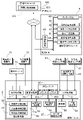
図4には、このトラクタに構築されている制御系が示されている。この実施形態の制御系には、グラフィカルユーザインターフェースを備えた汎用端末4と、トラクタの車体1や畔作業装置30の制御を行う制御ユニット5とが含まれている。制御ユニット5には上述した測位ユニット80も含まれている。測位ユニット80は、衛星測位機能を有する衛星測位ユニット80aと、慣性航法機能を有する慣性航法ユニット80bとを備えている。測位ユニット80は、衛星測位ユニット80aからの検出信号または慣性航法ユニット80bからの検出信号、あるいはその両方の信号に基づいて測位データを生成して、出力する。
FIG. 4 shows the control system built on this tractor. The control system of this embodiment includes a general-purpose terminal 4 provided with a graphical user interface, and a control unit 5 for controlling a vehicle body 1 of a tractor and a
トラクタの制御系の中核要素であり、コンピュータシステムとして構築されている制御ユニット5には、入出力インタフェースとして機能する、出力処理部7、入力処理部8、通信処理部70が備えられている。
The control unit 5, which is a core element of the control system of the tractor and is constructed as a computer system, includes an
出力処理部7は、トラクタに装備されている、車両走行機器群71、作業装置機器群72、報知デバイス73などと接続している。車両走行機器群71には、操舵モータ14(図1参照)や、非図示の、変速機構やエンジンユニットなど車両走行のために制御される機器が含まれている。作業装置機器群72には、畔作業装置30の駆動機構や、畔作業装置30を昇降させる昇降機構31などが含まれている。報知デバイス73には、ディスプレイやランプやスピーカが含まれている。報知デバイス73は、走行注意事項や自動操舵走行での目標走行経路からの外れなど、注意情報や警告情報を運転者や監視者に報知するために用いられる。通信処理部70は、制御ユニット5で処理されたデータを管理コンピュータ100に送信するとともに、管理コンピュータ100から種々のデータを受信する機能を有する。
The
入力処理部8は、走行系検出センサ群81、作業系検出センサ群82、自動手動切替操作具83などと接続している。走行系検出センサ群81には、エンジン回転数や変速状態などの走行状態を検出するセンサが含まれている。作業系検出センサ群82には、畔作業装置30の位置や傾きを検出するセンサ、作業負荷などを検出するセンサなどが含まれている。自動手動切替操作具83は、自動操舵で走行する自動走行モードと手動操舵で走行する手動操舵モードとのいずれかを選択するスイッチである。
The
制御ユニット5には、走行制御部50、自車位置算出部53、作業制御部54、走行経路設定部55、報知部56が備えられている。自車位置算出部53は、測位ユニット80から送られてくる測位データに基づいて、自動操舵に適した車体1の基準位置である自車位置を算出する。車両走行機器群71を制御する走行制御部50には、このトラクタが自動走行(自動操舵)と手動走行(手動操舵)の両方で走行可能に構成されているため、手動走行制御部51と自動走行制御部52とが含まれている。手動走行制御部51は、運転者による操作に基づいて車両走行機器群71を制御する。自動走行制御部52は、走行経路設定部55で設定された自動操舵の目標として設定された走行経路と自車位置との間の方位ずれ及び位置ずれを算出し、自動操舵指令を生成し、出力処理部7を介して操舵モータ14に出力する。自動走行制御部52は、変速指令や停車指令も出力する。この実施形態では、走行経路設定部55は、汎用端末4によって生成された走行経路を受け取り、トラクタの目標走行経路として設定する。
The control unit 5 includes a
作業制御部54は、畔作業装置30の動きを制御するために、作業装置機器群72に制御信号を与える。報知部56は、運転者や監視者に必要な情報を報知するための報知データ(表示データや音声データ)を生成して、計器パネルに組み込まれた報知デバイス73や、汎用端末4に送る。
The
汎用端末4は、タブレットコンピュータで構成されており、通信制御部40やタッチパネル60など、一般的なコンピュータシステムの諸機能を備え、車載LANによって、制御ユニット5とデータ交換可能に接続されている。さらに、汎用端末4は、遠隔地の管理センタKSに構築された管理コンピュータ100とも、無線回線やインターネットを通じて、データ交換可能である。
The general-purpose terminal 4 is composed of a tablet computer, has various functions of a general computer system such as a
さらに、この実施形態では、汎用端末4には、圃場管理モジュール6が、実質的にコンピュータプログラムとして備えられている。圃場管理モジュール6は、境界位置算出部61と、地図データ生成部62と、出入口決定部63と、走行経路生成部64とを備えている。
Further, in this embodiment, the general-purpose terminal 4 is provided with the
境界位置算出部61は、測位ユニット80からの測位データ、好ましくは衛星測位ユニット80aからの衛星測位データに基づいて、畔作業装置30の畔に対する作業箇所の位置座標である作業位置座標を算出し、その作業位置座標から畔と圃場面との間の境界線上の境界点(畔の立ち上がり箇所)の位置座標を算出する。作業箇所と境界点とが近接している場合には、作業位置座標がそのまま境界点の位置座標として用いられる。
The boundary
境界位置算出部61は、図2で例示しているように、圃場面の全周にわたって畔が形成されておらず、畔が欠損している欠損領域がある場合に、その欠損領域における境界点の位置座標も推定することができる。欠損領域における位置座標の推定は、以下に示すいくつかの方法で算出することができる。
(1)車体1が畔作業装置30の非作動状態(非畔作業状態)で欠損領域に沿って走行することで得られる車体1の基準点の位置座標を想定される境界点の位置にずらす演算から算出される。
(2)欠損領域の両端の位置(図2においてP1とP4とで示された位置)で算出された位置座標から、境界位置算出部61が欠損領域における境界点の位置座標を補間する。
(3)運転者がタッチパネル60を用いて欠損領域における境界線を入力し、入力された境界線に基づいて、境界位置算出部61が欠損領域における境界点の位置座標を算出する。
As illustrated in FIG. 2, the boundary
(1) The position coordinates of the reference point of the vehicle body 1 obtained by traveling along the defective region in the non-operating state (non-shore working state) of the vehicle body 1 are shifted to the position of the assumed boundary point. Calculated from the calculation.
(2) The boundary
(3) The driver inputs a boundary line in the defective area using the
地図データ生成部62は、境界位置算出部61によって経時的に算出された境界点の位置座標、または推定された境界点の位置座標に基づいて、圃場面の外形を示す圃場面地図データを生成する。
The map
出入口決定部63は、トタクタが圃場面へ進入及び圃場面から退出するための圃場出入口の位置座標を決定する。トタクタが圃場出入口を通過する際には、畔作業装置30への動力伝達は遮断されており、さらに、畔作業装置30は非作業姿勢(上方位置)に退避している。また、一般に圃場出入口は傾斜しており、車体1も傾斜することになるので、傾斜センサによりその傾斜を検知することができる。このような畔作業装置30の状態や車体1の状態から、トタクタが圃場出入口を通過していることが検知できる。トタクタの圃場出入口の通過時の測位データに基づいて算出される位置座標を用いて、出入口決定部63は、圃場出入口の位置座標を決定する。もちろん、出入口決定部63は、運転者がタッチパネル60を用いて入力したデータに基づいて、圃場出入口の位置座標を決定することも可能である。その際、運転者は、トタクタの圃場出入口の通過を確定した時点で、何らかの操作を行い、出入口決定部63は、その時点での位置座標が圃場出入口の位置座標であると決定する。決定された圃場出入口の位置座標は、地図データ生成部62に与えられ、圃場面地図データに書き込まれる。
The
走行経路生成部64は、地図データ生成部62によって生成された、圃場面の外形を示す圃場面地図データに基づいて、圃場面を作業(例えば、作業装置を耕耘装置に取り換えて行われる耕耘作業)する際に用いられる走行経路を生成して、走行経路設定部55に与える。圃場面地図データに、出入口の位置座標が含まれている場合、走行経路生成部64は、出入口の近傍を出発点とし、出入口の近傍を終了点とする走行経路を生成する。そのような走行経路の一例が図3に示されている。
The travel
図3で用いられている走行パターンは、圃場面の外周領域を渦巻き状に周回する周回走行パターンと、外周領域の内周側に位置する中央領域を直線状(又は湾曲状)に往復する直進走行パターンとからなる。周回走行パターンで用いられる走行経路は、圃場面の各辺に沿った直進経路と、圃場面の各コーナでの方向転換経路とからなる。直進走行パターンで用いられる走行経路は、複数の平行な直進経路と、各直進経路をつなぐUターン経路とからなる。外周領域の幅は、Uターン経路に必要な面積から決定される。直線経路は、圃場面の各辺に平行に延びるとともに、その間隔は、トラクタの作業幅(正確にはオーバーラップ幅を考慮した作業幅)に基づいて決定される。 The traveling pattern used in FIG. 3 is a circular traveling pattern that spirally orbits the outer peripheral region of the field scene and a straight line that reciprocates linearly (or curvedly) the central region located on the inner peripheral side of the outer peripheral region. It consists of a running pattern. The traveling route used in the orbiting traveling pattern consists of a straight route along each side of the field scene and a turning route at each corner of the field scene. The travel path used in the straight travel pattern consists of a plurality of parallel straight routes and a U-turn route connecting each straight route. The width of the outer peripheral region is determined from the area required for the U-turn path. The straight path extends parallel to each side of the field scene, and the spacing is determined based on the working width of the tractor (more precisely, the working width considering the overlap width).
さらに、農道から出入口を通過して圃場に進入し、内側走行経路と接続する進入経路、及び周回走行経路に接続して圃場から出入口を通過して農道に抜ける退出経路が決定される。耕耘作業の場合、先に直進走行パターンでの作業走行が行われ、次いで周回走行パターンでの作業走行が行われ、そのまま出入口を通って圃場から出るやり方が一般的である。したがって、進入経路は、出入口の通過方向に沿って延びて直進走行パターンにおける直進経路の端点にスムーズにつながるように決定され、退出経路は、出入口の通過方向に沿って延びて周回走行パターンの直進経路にスムーズにつながるように決定される。 Further, an approach route that passes through the entrance / exit from the farm road and enters the field and connects to the inner travel route, and an exit route that connects to the circuit traveling route and passes through the entrance / exit from the field to the farm road are determined. In the case of cultivating work, it is common that the work running in the straight running pattern is performed first, then the working running in the orbiting running pattern is carried out, and then the farm goes out of the field as it is through the doorway. Therefore, the approach route is determined to extend along the passage direction of the entrance and exit and smoothly connect to the end point of the straight route in the straight travel pattern, and the exit route extends along the passage direction of the entrance and exit and travels straight in the orbital travel pattern. It is decided to connect smoothly to the route.
走行経路生成部64は、このようにして生成された、進入経路、周回走行パターンでの走行経路、周回走行パターンでの走行経路、退出経路を順次つなぐことにより、この圃場面をトラクタが自動走行するための全ての走行経路を生成する。
The travel
この実施形態では、圃場管理モジュール6は、さらに起伏データ生成部65を備えている。起伏データ生成部65は、畔作業における、昇降機構31の昇降量、車体1の傾斜度、測位データに含まれている高さデータのうちの少なくとも1つを用いて、畔の高さ及び畔近傍の圃場面の起伏状態を示す起伏データを生成する。もちろん、起伏データ生成部65は、畔作業以外の圃場作業中においても、圃場面の起伏状態を示す起伏データを生成することができる。
In this embodiment, the
圃場管理モジュール6で生成されたデータは、通信制御部40を介して管理コンピュータ100の圃場情報格納部101に格納される。これにより、トラクタ以外の圃場作業車(田植機、コンバイン、施肥機など)との間で、圃場面地図データなどのデータ共有が可能となる。
The data generated by the
この実施形態では、制御ユニット5に、出入口通過認識部57が備えられている。出入口通過認識部57は、自車位置算出部53によって算出された車体1の位置座標と、出入口決定部63で決定された出入口の位置座標に基づいて、車体1の出入口の通過を認識し、その際、認識信号が出力される。認識信号が出力されると、報知部56は、車体1の出入口通過の際に守らなければならない制限条件を運転者に報知する。その報知内容は、片ブレーキの禁止、搭載作業装置の安定姿勢維持、低車速の維持、大きな操舵角の禁止などである。もちろん、認識信号が出力されると、自動的に、制限条件を守るべく、車両走行機器群71や作業装置機器群72が強制制御される構成を採用してもよい。
In this embodiment, the control unit 5 is provided with an entrance / exit
さらに、この実施形態では、畔作業装置30を用いた畔作業が効率的に行われるように、走行制御部50に方位維持制御部52aが備えられている。方位維持制御部52aは、所定距離の手動走行で取得された測位データに基づいて算出された基準走行方位を目標走行方位として、車体1を自動操舵する。方位維持制御部52aは、畔作業装置30を用いて畔を形成しながら所定距離だけ手動で直進走行している間に車体1の位置座標を取得し、当該位置座標に基づいて、その直進走行における走行方位(走行軌跡の向き)を求める。走行方位が求められると、方位維持制御部52aは、当該走行方位を目標走行方位として自動操舵を行う。これにより、運転者は、最初の数mを慎重に手動走行をするだけで、その後は、自動操舵で直線走行が行われるので、畔作業が簡単となる。
Further, in this embodiment, the traveling
〔別実施の形態〕
(1)上述した実施形態では、畔作業装置30は、トラクタに連結され、トラクタから動力を受けるものであった。これに代えて、畔作業装置30は、自走式または人力式(歩行型)で構成することができる。そのような畔作業装置30にも、本発明による圃場地図データ生成システムを搭載することで、上述した実施形態と同様な圃場地図データを生成することが可能である。この圃場地図データ生成システムは、畔作業装置30に測位ユニット80(衛星測位ユニット80aだけでもよい)、境界位置算出部61、地図データ生成部62を搭載することで、実現する。
[Another embodiment]
(1) In the above-described embodiment, the
(2)コンクリート製などの畔が形成されている圃場において、圃場地図データを生成するためには、畔を自動または手動で走行する畔走行車に、測位ユニット80(衛星測位ユニット80aだけでもよい)、境界位置算出部61、地図データ生成部62を搭載すればよい。
(2) In a field made of concrete or the like on which a shore is formed, in order to generate field map data, only the positioning unit 80 (
(3)図4で示された機能ブロック図における各機能部は、主に説明目的で区分けされている。実際には、各機能部は他の機能部と統合または複数の機能部に分けることができる。例えば、圃場管理モジュール6の少なくとも一部は制御ユニット5に構築されてもよい。また、簡易な圃場管理モジュール6は、スマートフォンなどの衛星測位可能な汎用機器を用いて構築することも可能である。
(3) Each functional unit in the functional block diagram shown in FIG. 4 is mainly divided for explanatory purposes. In practice, each functional unit can be integrated with other functional units or divided into a plurality of functional units. For example, at least a part of the
本発明は、畔作業装置を装備する圃場作業車、及び畔作業装置単体に適用可能である。 The present invention is applicable to a field work vehicle equipped with a shore work device and a shore work device alone.
1 :車体(走行車体)
4 :汎用端末
30 :畔作業装置
5 :制御ユニット
50 :走行制御部
51 :手動走行制御部
52 :自動走行制御部
52a :方位維持制御部
53 :自車位置算出部
54 :作業制御部
55 :走行経路設定部
56 :報知部
57 :出入口通過認識部
6 :圃場管理モジュール
61 :境界位置算出部
62 :地図データ生成部
63 :出入口決定部
64 :走行経路生成部
65 :起伏データ生成部
73 :報知デバイス
80 :測位ユニット
80a :衛星測位ユニット
80b :慣性航法ユニット
100 :管理コンピュータ
101 :圃場情報格納部
P1 :地点
P2 :地点
P3 :地点
P4 :地点
SA :GNSS衛星
1: Body (running body)
4: General-purpose terminal 30: Side work device 5: Control unit 50: Travel control unit 51: Manual travel control unit 52: Automatic
Claims (8)
走行車体と、
圃場の畔に対する作業を行うために前記走行車体に装備された畔作業装置と、
測位データに基づいて算出された車体基準位置と、当該車体基準位置と前記畔作業装置と当該畔作業装置の前記畔に対する作業箇所との位置関係から前記作業箇所の位置座標を算出し、算出された前記作業箇所の位置座標に基づいて、前記畔と圃場面との間の境界線上の境界点の位置座標を算出する境界位置算出部と、
前記境界位置算出部によって経時的に算出された前記境界点の位置座標に基づいて、前記圃場面の外形を示す圃場面地図データを生成する地図データ生成部と、を備えた圃場作業車。 It ’s a field work vehicle,
With the running body
The shore work device equipped on the traveling vehicle body to perform work on the shore of the field,
The position coordinates of the work location are calculated and calculated from the vehicle body reference position calculated based on the positioning data, the positional relationship between the vehicle body reference position, the shore work device, and the work location of the shore work device with respect to the shore. A boundary position calculation unit that calculates the position coordinates of the boundary point on the boundary line between the shore and the field scene based on the position coordinates of the work place.
A field work vehicle including a map data generation unit that generates field scene map data indicating the outer shape of the field scene based on the position coordinates of the boundary point calculated over time by the boundary position calculation unit.
前記昇降機構の昇降量、前記走行車体の傾斜度、前記測位データに含まれている高さデータのうちの少なくとも1つを用いて、前記圃場面の起伏状態を示す起伏データを生成する起伏データ生成部が備えられている請求項1から6のいずれか一項に記載の圃場作業車。 The shore work device is mounted on the traveling vehicle body via an elevating mechanism.
Undulation data that generates undulation data indicating the undulation state of the field scene using at least one of the elevating amount of the elevating mechanism, the inclination of the traveling vehicle body, and the height data included in the positioning data. The field work vehicle according to any one of claims 1 to 6, which is provided with a generator.
測位データに基づいて算出された車体の車体基準位置と、当該車体基準位置と前記畔に対する作業を行うために前記車体に装備された畔作業装置の前記畔に対する作業箇所との位置関係から前記作業箇所の位置座標を算出し、算出された前記作業箇所の位置座標に基づいて、前記畔と前記圃場面との間の境界線上の境界点の位置座標を算出する境界位置算出部と、
前記境界位置算出部によって経時的に算出された前記境界点の位置座標に基づいて前記圃場面地図データを生成する地図データ生成部と、を備えた圃場地図データ生成システム。 It is a field map data generation system that generates field map data showing the outline of the field scene bounded by the shore of the field.
The work is based on the positional relationship between the vehicle body reference position calculated based on the positioning data and the vehicle body reference position and the work location of the shore work device equipped on the vehicle body for performing the work on the shore. A boundary position calculation unit that calculates the position coordinates of the location and calculates the position coordinates of the boundary point on the boundary line between the shore and the field scene based on the calculated position coordinates of the work location.
A field map data generation system including a map data generation unit that generates the field scene map data based on the position coordinates of the boundary point calculated over time by the boundary position calculation unit.
Priority Applications (1)
| Application Number | Priority Date | Filing Date | Title |
|---|---|---|---|
| JP2018239576A JP7069002B2 (en) | 2018-12-21 | 2018-12-21 | Field work vehicle and field map data generation system |
Applications Claiming Priority (1)
| Application Number | Priority Date | Filing Date | Title |
|---|---|---|---|
| JP2018239576A JP7069002B2 (en) | 2018-12-21 | 2018-12-21 | Field work vehicle and field map data generation system |
Publications (2)
| Publication Number | Publication Date |
|---|---|
| JP2020099240A JP2020099240A (en) | 2020-07-02 |
| JP7069002B2 true JP7069002B2 (en) | 2022-05-17 |
Family
ID=71138884
Family Applications (1)
| Application Number | Title | Priority Date | Filing Date |
|---|---|---|---|
| JP2018239576A Active JP7069002B2 (en) | 2018-12-21 | 2018-12-21 | Field work vehicle and field map data generation system |
Country Status (1)
| Country | Link |
|---|---|
| JP (1) | JP7069002B2 (en) |
Families Citing this family (2)
| Publication number | Priority date | Publication date | Assignee | Title |
|---|---|---|---|---|
| JP7343405B2 (en) * | 2020-01-14 | 2023-09-12 | 株式会社クボタ | agricultural vehicle |
| CN114485610B (en) * | 2021-12-27 | 2023-07-18 | 广州极飞科技股份有限公司 | Vector map construction method and device and path planning method and device |
Citations (8)
| Publication number | Priority date | Publication date | Assignee | Title |
|---|---|---|---|---|
| JP2015112070A (en) | 2013-12-12 | 2015-06-22 | 株式会社クボタ | Field work machine |
| JP2016024540A (en) | 2014-07-17 | 2016-02-08 | 株式会社クボタ | Traveling work machine and automatic steering system used therein |
| JP2016156690A (en) | 2015-02-24 | 2016-09-01 | 井関農機株式会社 | Working vehicle |
| JP2017046656A (en) | 2015-09-03 | 2017-03-09 | 松山株式会社 | Guide system for agricultural implement |
| JP2018116608A (en) | 2017-01-20 | 2018-07-26 | 株式会社クボタ | Travel route generating device and travel route generating program |
| JP2018151845A (en) | 2017-03-13 | 2018-09-27 | 井関農機株式会社 | Working ground map data preparation device of agricultural work vehicle |
| US20180325015A1 (en) | 2017-04-18 | 2018-11-15 | CropZilla Software, Inc. | Machine Control System Providing Actionable Management Information and Insight Using Agricultural Telematics |
| JP2018184100A (en) | 2017-04-26 | 2018-11-22 | 株式会社クボタ | Working vehicle |
-
2018
- 2018-12-21 JP JP2018239576A patent/JP7069002B2/en active Active
Patent Citations (8)
| Publication number | Priority date | Publication date | Assignee | Title |
|---|---|---|---|---|
| JP2015112070A (en) | 2013-12-12 | 2015-06-22 | 株式会社クボタ | Field work machine |
| JP2016024540A (en) | 2014-07-17 | 2016-02-08 | 株式会社クボタ | Traveling work machine and automatic steering system used therein |
| JP2016156690A (en) | 2015-02-24 | 2016-09-01 | 井関農機株式会社 | Working vehicle |
| JP2017046656A (en) | 2015-09-03 | 2017-03-09 | 松山株式会社 | Guide system for agricultural implement |
| JP2018116608A (en) | 2017-01-20 | 2018-07-26 | 株式会社クボタ | Travel route generating device and travel route generating program |
| JP2018151845A (en) | 2017-03-13 | 2018-09-27 | 井関農機株式会社 | Working ground map data preparation device of agricultural work vehicle |
| US20180325015A1 (en) | 2017-04-18 | 2018-11-15 | CropZilla Software, Inc. | Machine Control System Providing Actionable Management Information and Insight Using Agricultural Telematics |
| JP2018184100A (en) | 2017-04-26 | 2018-11-22 | 株式会社クボタ | Working vehicle |
Also Published As
| Publication number | Publication date |
|---|---|
| JP2020099240A (en) | 2020-07-02 |
Similar Documents
| Publication | Publication Date | Title |
|---|---|---|
| CN108334065B (en) | Travel route generation device and travel route generation program | |
| US10598505B2 (en) | Travel route generation apparatus and method for generating travel route | |
| US10231374B2 (en) | Travel support system, travel support method, and work vehicle | |
| JP6727944B2 (en) | Field travel route generation system and field work vehicle | |
| US20180011495A1 (en) | Route search method, route search system, non-transitory computer-readable storage medium, and work vehicle | |
| CN108334068B (en) | Travel route generation device | |
| JP2018073050A (en) | Running route creating device | |
| JP6812247B2 (en) | Travel route generator and travel route generation program | |
| KR102534336B1 (en) | Route generation system | |
| JP6884092B2 (en) | Travel route selection system for work vehicles and work vehicles | |
| JP7072496B2 (en) | Control device for self-driving work vehicles | |
| US10989541B2 (en) | Travel route generation device and travel route generation method | |
| JP7069285B2 (en) | Field work vehicle | |
| JP7069002B2 (en) | Field work vehicle and field map data generation system | |
| JP7479425B2 (en) | Traveling work machine | |
| JP7045979B2 (en) | Traveling work machine | |
| WO2020129704A1 (en) | Travel working machine | |
| JP7113875B2 (en) | A route search program, a route search system, and a work vehicle incorporating this route search system | |
| WO2022149389A1 (en) | Automatic travel system and automatic travel method |
Legal Events
| Date | Code | Title | Description |
|---|---|---|---|
| A621 | Written request for application examination |
Free format text: JAPANESE INTERMEDIATE CODE: A621 Effective date: 20201225 |
|
| A977 | Report on retrieval |
Free format text: JAPANESE INTERMEDIATE CODE: A971007 Effective date: 20211029 |
|
| A131 | Notification of reasons for refusal |
Free format text: JAPANESE INTERMEDIATE CODE: A131 Effective date: 20211116 |
|
| A521 | Request for written amendment filed |
Free format text: JAPANESE INTERMEDIATE CODE: A523 Effective date: 20220114 |
|
| A131 | Notification of reasons for refusal |
Free format text: JAPANESE INTERMEDIATE CODE: A131 Effective date: 20220201 |
|
| A521 | Request for written amendment filed |
Free format text: JAPANESE INTERMEDIATE CODE: A523 Effective date: 20220330 |
|
| TRDD | Decision of grant or rejection written | ||
| A01 | Written decision to grant a patent or to grant a registration (utility model) |
Free format text: JAPANESE INTERMEDIATE CODE: A01 Effective date: 20220405 |
|
| A61 | First payment of annual fees (during grant procedure) |
Free format text: JAPANESE INTERMEDIATE CODE: A61 Effective date: 20220502 |
|
| R150 | Certificate of patent or registration of utility model |
Ref document number: 7069002 Country of ref document: JP Free format text: JAPANESE INTERMEDIATE CODE: R150 |