JP7065780B6 - Methods and equipment for packet start detection in digital communication systems - Google Patents
Methods and equipment for packet start detection in digital communication systems Download PDFInfo
- Publication number
- JP7065780B6 JP7065780B6 JP2018546844A JP2018546844A JP7065780B6 JP 7065780 B6 JP7065780 B6 JP 7065780B6 JP 2018546844 A JP2018546844 A JP 2018546844A JP 2018546844 A JP2018546844 A JP 2018546844A JP 7065780 B6 JP7065780 B6 JP 7065780B6
- Authority
- JP
- Japan
- Prior art keywords
- packet start
- subset
- start information
- stage
- sop
- Prior art date
- Legal status (The legal status is an assumption and is not a legal conclusion. Google has not performed a legal analysis and makes no representation as to the accuracy of the status listed.)
- Active
Links
Images


Classifications
-
- H—ELECTRICITY
- H04—ELECTRIC COMMUNICATION TECHNIQUE
- H04B—TRANSMISSION
- H04B13/00—Transmission systems characterised by the medium used for transmission, not provided for in groups H04B3/00 - H04B11/00
- H04B13/005—Transmission systems in which the medium consists of the human body
-
- H—ELECTRICITY
- H04—ELECTRIC COMMUNICATION TECHNIQUE
- H04L—TRANSMISSION OF DIGITAL INFORMATION, e.g. TELEGRAPHIC COMMUNICATION
- H04L1/00—Arrangements for detecting or preventing errors in the information received
- H04L1/0078—Avoidance of errors by organising the transmitted data in a format specifically designed to deal with errors, e.g. location
- H04L1/0083—Formatting with frames or packets; Protocol or part of protocol for error control
-
- H—ELECTRICITY
- H04—ELECTRIC COMMUNICATION TECHNIQUE
- H04L—TRANSMISSION OF DIGITAL INFORMATION, e.g. TELEGRAPHIC COMMUNICATION
- H04L27/00—Modulated-carrier systems
- H04L27/26—Systems using multi-frequency codes
- H04L27/2601—Multicarrier modulation systems
- H04L27/2647—Arrangements specific to the receiver only
- H04L27/2655—Synchronisation arrangements
- H04L27/2656—Frame synchronisation, e.g. packet synchronisation, time division duplex [TDD] switching point detection or subframe synchronisation
-
- H—ELECTRICITY
- H04—ELECTRIC COMMUNICATION TECHNIQUE
- H04L—TRANSMISSION OF DIGITAL INFORMATION, e.g. TELEGRAPHIC COMMUNICATION
- H04L7/00—Arrangements for synchronising receiver with transmitter
- H04L7/04—Speed or phase control by synchronisation signals
- H04L7/041—Speed or phase control by synchronisation signals using special codes as synchronising signal
- H04L7/042—Detectors therefor, e.g. correlators, state machines
-
- A—HUMAN NECESSITIES
- A61—MEDICAL OR VETERINARY SCIENCE; HYGIENE
- A61B—DIAGNOSIS; SURGERY; IDENTIFICATION
- A61B5/00—Measuring for diagnostic purposes; Identification of persons
- A61B5/0002—Remote monitoring of patients using telemetry, e.g. transmission of vital signals via a communication network
- A61B5/0015—Remote monitoring of patients using telemetry, e.g. transmission of vital signals via a communication network characterised by features of the telemetry system
- A61B5/0024—Remote monitoring of patients using telemetry, e.g. transmission of vital signals via a communication network characterised by features of the telemetry system for multiple sensor units attached to the patient, e.g. using a body or personal area network
-
- A—HUMAN NECESSITIES
- A61—MEDICAL OR VETERINARY SCIENCE; HYGIENE
- A61B—DIAGNOSIS; SURGERY; IDENTIFICATION
- A61B5/00—Measuring for diagnostic purposes; Identification of persons
- A61B5/0002—Remote monitoring of patients using telemetry, e.g. transmission of vital signals via a communication network
- A61B5/0026—Remote monitoring of patients using telemetry, e.g. transmission of vital signals via a communication network characterised by the transmission medium
- A61B5/0028—Body tissue as transmission medium, i.e. transmission systems where the medium is the human body
Description
いくつかの実施形態は、排他的ではないが特に身体結合装置で使用するためのパケット開始(SOP)検出のための方法及び装置に関する。 Some embodiments relate to methods and devices for packet initiation (SOP) detection, although not exclusive, especially for use in body binding devices.
身体結合通信(BCC)又は身体ベース通信が、電気電子技術者協会(IEEE)の802.15.6タスクグループによって標準化されるように、ボディエリアネットワーク(BAN)の基礎として提案されている。BCCは、人間又は動物の身体にある又は近接している複数の装置間で情報の交換を許容する。これは、体表面への低エネルギー電界の容量又はガルバニック結合によって達成されることができる。 Body-coupling communication (BCC) or body-based communication has been proposed as the basis for a body area network (BAN) to be standardized by the 802.15.6 task group of the Institute of Electrical and Electronics Engineers (IEEE). BCC allows the exchange of information between multiple devices in or in close proximity to the human or animal body. This can be achieved by the capacitance of a low energy electric field or galvanic coupling to the body surface.
身体結合通信(BCC)システムにおいて、ユーザの身体にわたって信号を介して送信装置から受信器装置に情報が送信される。身体結合通信は、情報を送信するために電界を活用する。 In a blind carbon copy (BCC) system, information is transmitted from the transmitter to the receiver device via a signal across the user's body. Body-coupled communication utilizes an electric field to transmit information.
身体結合通信(BCC)は通信路として人体を使用する。それは、人体と接触している装置間でその人体にわたってワイヤレス通信を可能にする。信号は、空気を通しての代わりに身体にわたって伝達される。そのため、通信は、身体に近い領域に限定される。したがって、身体に位置する、接続される、又は近接して置かれる装置間で通信が可能である。 Body-bound communication (BCC) uses the human body as a communication channel. It enables wireless communication across the human body between devices in contact with the human body. The signal is transmitted across the body instead of through the air. Therefore, communication is limited to areas close to the body. Therefore, communication is possible between devices located on the body, connected, or placed in close proximity.
ここで、知られているパケット開始(SOP)検出器203を図示する図6を参照する。パケット開始データを含むフィールドを有するデータパケット300が受信される。パケット開始検出器は、基準SOPデータを有する基準SOPバッファ601、受信したデータパケットからSOPを受け取るSOPバッファ602、及び比較回路603を有する。比較回路は、基準SOPと受信したSOPとの間で一致があるかどうかを判定し、適切な出力604を提供することになる。比較回路は、受信したメッセージにおけるSOPデータを検出するために並列マルチビット相関(PMBC)手法を使用する。
Here we refer to FIG. 6, which illustrates the known packet start (SOP)
米国特許出願公開第2012/027149号では、連続的に送られるシフトレジスタと単一の基準語との間で一致が検査される同期検出器を記載している。 U.S. Patent Application Publication No. 2012/027149 describes a synchronous detector that checks for a match between a continuously transmitted shift register and a single reference language.
EP0549247では、奇数及び偶数フレーム同期シーケンスに対する比較の結果の論理和がとられるD2 MACシステムのための同期検出器を記載している。 EP0549247 describes a synchronization detector for a D2 MAC system in which the logical sum of the results of comparisons for odd and even frame synchronization sequences is taken.
特開昭6133040では、アナログ同期検出器を記載している。 Japanese Patent Application Laid-Open No. 613340 describes an analog synchroscope.
CA2215380では、同期検出器を有するコーディングシステム及び装置を記載している。 CA2215380 describes a coding system and device with a sync detector.
この技法はいくつかの状況でうまく機能する。信号対雑音比が低い場合、検出は信頼できなくなることがあり、典型的な解決策はSOPをより長くすることである。しかしながら、SOPの増加した長さでは、SOP検出器の複雑度及び電力消費の増加が一定の用途で不利となる。 This technique works well in some situations. If the signal-to-noise ratio is low, the detection can be unreliable and the typical solution is to make the SOP longer. However, with the increased length of SOP, the complexity of the SOP detector and the increased power consumption are disadvantageous in certain applications.
一態様によれば、パケット開始情報を含む入力データを受信するように構成された入力部と、基準パケット開始情報のそれぞれの部分集合と受信したパケット開始情報のそれぞれの部分集合との間で一致があるかどうかを判定するように構成された第1のステージであって、受信したパケット開始情報の部分集合の各々及び基準パケット開始情報のそれぞれの部分集合に対して上記判定することを繰り返すように構成され、基準パケット開始情報のそれぞれの部分集合と受信したパケット開始情報のそれぞれの部分集合との間で一致があればカウンタの値が変更される第1のステージと、第1のステージの上記判定することについての、カウンタの値と閾値との比較に依存してパケット開始検出出力を提供するように構成された出力部とを備えるパケット開始検出器が提供される。 According to one aspect, an input unit configured to receive input data including packet start information is matched between each subset of reference packet start information and each subset of received packet start information. It is a first stage configured to determine if there is, and repeats the above determination for each of the received packet start information subsets and each of the reference packet start information subsets. If there is a match between each subset of the reference packet start information and each subset of the received packet start information, the value of the counter is changed in the first stage and the first stage. A packet start detector is provided that includes an output unit configured to provide a packet start detection output depending on a comparison of a counter value with a threshold for the determination.
より大きな長さのSOPが使用される場合、本発明のいくつかの実施形態は、より小型且つ/又は電力効率的なSOP検出器が提供されるのを許容する。これは、パケット開始情報の部分集合に注目するために同じ回路が使用されるからである。これは、必要とされる回路量が低減されることができることを意味する。これは電力消費も低減させる。 When larger length SOPs are used, some embodiments of the invention allow smaller and / or power efficient SOP detectors to be provided. This is because the same circuit is used to focus on the subset of packet start information. This means that the amount of circuit required can be reduced. This also reduces power consumption.
カウンタが、基準パケット開始情報のどのそれぞれの部分集合が第1のステージによって使用されるかを制御するように構成される。これは、基準パケット開始情報の各部分集合が正しい順序で使用されることを確実にする。他の実施形態において異なる論理が使用されることが認識されるべきである。 Counters are configured to control which subset of the reference packet start information is used by the first stage. This ensures that each subset of the reference packet start information is used in the correct order. It should be recognized that different logics are used in other embodiments.
基準パケット開始情報のそれぞれの部分集合と受信したパケット開始情報のそれぞれの部分集合との間で一致があればカウンタの値が変更される。カウンタはインクリメント又はデクリメントされる。このように、カウンタの所与の値が達成されると、SOPの全体が検査されたと判定されることができる。 If there is a match between each subset of the reference packet start information and each subset of the received packet start information, the value of the counter is changed. The counter is incremented or decremented. Thus, when a given value of the counter is achieved, it can be determined that the entire SOP has been inspected.
第1のステージは、一致があるかどうかを判定するために閾値を使用するように構成されており、閾値が各部分集合に対して設定可能である。これは、閾値が、例えば雑音レベルに応じて変更されることを可能にする。 The first stage is configured to use a threshold to determine if there is a match, and the threshold can be set for each subset. This allows the threshold to be changed, for example, depending on the noise level.
第1のステージは、受信したパケット開始情報部分集合とそれぞれの基準パケット開始情報部分集合との間でそれぞれの排他的論理和を行うように構成された排他的論理和機能を含む。排他的論理和機能は有利には、基準及び受信値が同じであるときに1つの値を、そして基準及び受信値が異なるときに異なる値を提供することになる。 The first stage includes an exclusive OR function configured to perform an exclusive OR between the received packet start information subset and each reference packet start information subset. The exclusive OR function will advantageously provide one value when the reference and received values are the same, and different values when the reference and received values are different.
第1のステージは、排他的論理和機能の出力を加算して合計した出力を、第1の比較器に提供するように構成された加算器機能を含み、第1の比較器は、上記合計した出力と閾値とを比較するように構成される。有利には、排他的論理和機能の出力を合計することによって、基準及び受信したパケット開始情報間の一致の程度を示すことになる値が得られる。この値を閾値と比較することによって、情報のそれぞれの部分集合が一致であると考えられるか否かが簡単に判定されることができる。 The first stage includes an adder function configured to provide the first comparator with the sum of the outputs of the exclusive OR functions, the first comparator being the sum of the above. It is configured to compare the output and the threshold value. Advantageously, by summing the outputs of the exclusive-OR function, a value that will indicate the degree of matching between the reference and the received packet start information is obtained. By comparing this value with the threshold, it can be easily determined whether or not each subset of the information is considered to be a match.
第1のステージは、パケット開始情報の全ての部分集合が一致すると判定されれば、出力部によってパケット開始検出出力が出力されるように構成される。これは、いずれかのそれぞれの部分集合が一致しなければ、一致がないと考えられるという点で実装するのが簡単である。 The first stage is configured so that the output unit outputs a packet start detection output if it is determined that all the subsets of the packet start information match. This is easy to implement in that if any subset of each does not match, then it is considered non-matching.
パケット開始検出器は、パケット開始の全ての部分集合が一致と判定されたかどうかを判定し、そうであれば出力部によってパケット開始検出出力が出力されるようにするための第2の比較器を備える。 The packet start detector determines if all subsets of the packet start have been determined to match, and if so, a second comparator to ensure that the output unit outputs the packet start detection output. Be prepared.
パケット開始検出器は、第1のステージと並列に配置される第2のステージであって、受信したパケット開始情報のそれぞれの部分集合を基準パケット開始情報のそれぞれの部分集合の反転と比較するように構成された第2のステージを備え、出力部は、第1のステージ又は第2のステージの上記判定することに依存してパケット開始検出出力を提供するように構成される。これは、共通接地を有する装置に関して有用である。検出器はしたがって、受信したメッセージを反対極性であると解釈する(すなわち2進数の1は0と解釈され、その逆も同じである)。したがって、第2のステージを有することによって、SOP検出器は両方の可能な極性を考慮することができる。 The packet start detector is a second stage arranged in parallel with the first stage so that each subset of the received packet start information is compared with the inversion of each subset of the reference packet start information. The output unit is configured to provide a packet start detection output depending on the determination of the first stage or the second stage. This is useful for devices with a common ground. The detector therefore interprets the received message as having opposite polarity (ie, the binary number 1 is interpreted as 0 and vice versa). Therefore, by having a second stage, the SOP detector can take into account both possible polarities.
出力部は、パケット開始検出出力が第1のステージ又は第2のステージの上記判定することに依存しているかを示す情報を出力するように構成される。いくつかの実施形態において、これは、パケットの内容を理解するために使用される。 The output unit is configured to output information indicating whether the packet start detection output depends on the determination of the first stage or the second stage. In some embodiments, this is used to understand the contents of the packet.
別の態様によれば、上記したようなパケット開始検出器を備える身体結合装置が提供される。身体結合装置は有利には、低電力装置であるべきであり、且ついくつかの実施形態によってサポートされるより長いパケット開始情報を必要とする比較的雑音が多い要件で動作される。 According to another aspect, a body coupling device including the packet start detector as described above is provided. The body coupling device should advantageously be a low power device and is operated with relatively noisy requirements that require longer packet start information supported by some embodiments.
別の態様によれば、受信したパケット開始情報の第1の部分集合を受け取るステップと、受信したパケット開始情報の第1の部分集合を基準のそれぞれの第1の部分集合と比較して、一致があるかどうかを判定するステップと、受信したパケット開始情報の後続の部分集合及び基準パケット開始情報のそれぞれの部分集合に対して上記受け取るステップ及び比較するステップを繰り返すステップと、上記比較するステップに依存してパケット開始検出出力を提供するステップとを有するパケット開始を検出する方法が提供される。 According to another aspect, the step of receiving the first subset of the received packet start information and the first subset of the received packet start information are compared and matched with their respective first subsets of the reference. In the step of determining whether or not there is, the step of repeating the above-mentioned receiving step and the above-mentioned comparison step for each subsequent subset of the received packet start information and the respective subset of the reference packet start information, and the above-mentioned comparison step. A method of detecting a packet start with a step of depending on providing a packet start detection output is provided.
比較するステップは、一致があるかどうかを判定するために閾値を使用することを有する。 The step of comparison involves using a threshold to determine if there is a match.
比較するステップは、受信したパケット開始情報の第1の部分集合に関しては第1の閾値を、及び受信したパケット開始情報の少なくとも1つの他の部分集合に関しては第2の異なる閾値を使用することを有する。 The step of comparison is to use a first threshold for the first subset of received packet start information and a second different threshold for at least one other subset of received packet start information. Have.
本方法は、パケット開始情報の全ての部分集合が一致すると判定されればパケット開始検出出力を提供するステップを有する。 The method has a step of providing a packet start detection output if it is determined that all subsets of the packet start information match.
本方法は、基準パケット開始情報のどのそれぞれの部分集合が使用されるかを制御するためにカウント値を使用するステップを有してもよい。 The method may include a step of using the count value to control which subset of the reference packet start information is used.
本方法は、基準パケット開始情報のそれぞれの部分集合と受信したパケット開始情報のそれぞれの部分集合との間で一致があればカウント値を変更するステップを有する。 The method comprises a step of changing the count value if there is a match between each subset of the reference packet start information and each subset of the received packet start information.
本方法は、受信したパケット開始情報部分集合とそれぞれの基準パケット開始情報部分集合との間で排他的論理和機能を行うステップを有してもよい。 The method may include a step of performing an exclusive OR function between the received packet start information subset and each reference packet start information subset.
本方法は、排他的論理和の結果を加算して合計した出力を提供する加算機能を行うステップと、合計した出力を閾値と比較するステップとを有してもよい。 The method may include a step of performing an addition function that adds up the results of the exclusive OR and provides a summed output, and a step of comparing the summed output with a threshold.
本方法は、基準パケット開始情報の反転を使用して上記方法を繰り返すステップを有してもよく、パケット開始検出出力は、基準パケット開始情報又はその反転を使用する上記判定するステップに依存している。 The method may include a step of repeating the above method using inversion of the reference packet start information, and the packet start detection output depends on the reference packet start information or the determination step using the inversion thereof. There is.
本方法は、パケット開始検出出力が基準パケット開始情報又はその反転に依存しているかを示す情報を提供するステップを有してもよい。 The method may include a step of providing information indicating whether the packet start detection output depends on the reference packet start information or its inversion.
すなわち、本実施形態では、様々な雑音条件下の改善されたパケット開始(SOP)検出の方法を記載する。 That is, the present embodiment describes an improved method of packet initiation (SOP) detection under various noise conditions.
ここで、いくつかの実施形態が単に例として且つ添付の図を参照して記載されることになる。 Here, some embodiments will be described merely as examples and with reference to the accompanying figures.
いくつかの実施形態は、パケット開始情報を含む入力データを受信するように構成された入力部と、基準パケット開始情報のそれぞれの部分集合と受信したパケット開始情報のそれぞれの部分集合との間で一致があるかどうかを判定するように構成された第1のステージであって、受信したパケット開始情報の部分集合の各々及び基準パケット開始情報のそれぞれの部分集合に対して判定することを繰り返すように構成された第1のステージと、第1のステージの判定することに依存してパケット開始検出出力を提供するように構成された出力部とを備えるパケット開始検出器を提供する。より大きな長さのSOPが使用される場合、本発明のいくつかの実施形態は、より小型且つ/又は電力効率的なSOP検出器が提供されるのを許容する。これは、パケット開始情報の部分集合に注目するために同じ回路が使用されるからである。これは、必要とされる回路量が低減されることができることを意味する。これは電力消費も低減させる。 Some embodiments are between an input unit configured to receive input data, including packet start information, and each subset of reference packet start information and each subset of received packet start information. The first stage, configured to determine if there is a match, repeats the determination for each of the received packet start information subsets and each of the reference packet start information subsets. Provided is a packet start detector comprising a first stage configured in the above and an output unit configured to provide a packet start detection output depending on the determination of the first stage. When larger length SOPs are used, some embodiments of the invention allow smaller and / or power efficient SOP detectors to be provided. This is because the same circuit is used to focus on the subset of packet start information. This means that the amount of circuit required can be reduced. This also reduces power consumption.
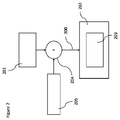
ここで、第1のBCC装置101及び第2のBCC装置102を備えるワイヤレスボディエリアネットワーク(WBAN)100を図示する図1を参照する。いくつかの実施形態において、3つ以上のBCC装置が活用される。第1のBCC装置101は、人104の身体における通信路103を介して第2のBCC装置102と通信することができる。例えば、第1のBCC装置101は送信器201を含み、第2のBCC装置102は受信器202を含む。第1のBCC装置101が送信器も受信器も有するか又は送信器だけを有してもよいことが認識されるべきである。第2のBCC装置102は、送信器も受信器も有するか又は受信器だけを有してもよい。
Here, reference is made to FIG. 1 illustrating a wireless body area network (WBAN) 100 comprising a
ここで、BCC通信システム200を概略的に図示する図2を参照する。いくつかの実施形態において、送信器201は、通信路103を介して受信器202にメッセージパケット300を送信する。いくつかの実施形態において、受信器202は、パケット開始(SOP)検出器203に受信したメッセージパケット300を渡す。メッセージパケット300が通信路103を介して送信器201から受信器202に伝わるにつれて、メッセージパケット300は、潜在的なBCC通信路雑音要因205により雑音204が多くなる。典型的に、BCC通信路雑音には2つの形態、連続雑音及びバースト雑音がある。連続雑音エラーはメッセージパケット全体にわたってランダムに拡散される。バースト雑音エラーは連続ビットに影響する。
Here, reference is made to FIG. 2, which schematically illustrates the BCC communication system 200. In some embodiments, the
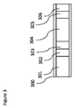
ここで、送信器201から受信器202に送信されるデータパケット300の実施形態を図示する図3を参照する。いくつかの実施形態において、データパケット300は例えば、プリアンブル301、パケット開始(SOP)インジケータ302、パケット長インジケータ(PLI)303、データバイト304、巡回冗長検査305及びパケット終了インジケータ(EOP)306を備える。
Here, reference is made to FIG. 3, which illustrates an embodiment of the
パケット長インジケータ(PLI)303は、パケット300に存在するデータバイト304の数について受信器202に情報を提供する。巡回冗長検査(CRC)305は、メッセージ(データバイト)304におけるエラーを検出するために活用される。データバイト304に先行するプリアンブル301は一連のゼロから成る。プリアンブルは100μs期間程度持続する。プリアンブル301は、クロック同期目的で後述することになるアナログフロントエンド(AFE)によって使用される。パケットの開始(SOP)302は、データパケット300の開始を識別するために受信器202によって使用される。SOP302が正しく検出されれば、それはパケット再送信の必要を低減させる。受信器がパケットの開始を検出することができなければ、パケット全体が失われ、情報を復元するためにその情報の再送信が必要とされる。再送信の数が低減されれば、これは通信スループット(実効データレート)を改善することになる。実効データレートは、受信器に達した情報の尺度である。実効データレートは、再送信及び喪失パケットによる全ての損失を考慮する。
The packet length indicator (PLI) 303 provides information to the
他の実施形態において他のデータパケット形式が使用されることが認識されるべきである。1つ又は複数のフィールドが省略されてもよい。1つ又は複数の追加フィールドが設けられてもよい。フィールドの順序は変更されてもよい。 It should be recognized that other data packet formats are used in other embodiments. One or more fields may be omitted. One or more additional fields may be provided. The order of the fields may be changed.
いくつかの実施形態は集積回路身体結合通信(BCC)送受信器を提供する。 Some embodiments provide integrated circuit body coupling communication (BCC) transmitters and receivers.
身体結合通信(BCC)システムの課題の1つは、比較的低電力動作で高堅牢性を達成することができる送受信器アーキテクチャの形態である。これはいくつかの実施形態によって達成される。 One of the challenges of body-coupling communication (BCC) systems is the form of a transmitter / receiver architecture that can achieve high robustness at relatively low power operation. This is achieved by some embodiments.
身体結合システムは有利には低消費電力を伴う。低消費電力は例えば低熱放散を伴う傾向がある。これは、装置がユーザの皮膚に対して使用されている場合に有利である。低消費電力は、装置が再充電される必要がある、又はエネルギー供給が限られている(例えば運動又は太陽エネルギー)用途で有利である。 The body-coupling system is advantageously associated with low power consumption. Low power consumption tends to be accompanied by, for example, low heat dissipation. This is advantageous when the device is used against the user's skin. Low power consumption is advantageous in applications where the device needs to be recharged or the energy supply is limited (eg kinetic or solar energy).
実施形態は任意の他の適切な通信システムにおける用途を有する。通信システムは低消費電力を伴っても又は伴わなくてもよい。 The embodiments have uses in any other suitable communication system. The communication system may or may not have low power consumption.
いくつかの実施形態は、送信器と受信器との間の距離が利用可能な電力と比較して比較的大きい場合に使用される。 Some embodiments are used when the distance between the transmitter and the receiver is relatively large compared to the available power.
送受信器は、いくつかの実施形態において単一の集積回路によって実装される。他の実施形態において、送受信器は、より大きい機能又は装置に組み込まれる。いくつかの実施形態において、1つの装置が送信器を有し、別の装置が受信器を有する。いくつかの実施形態において、別々の送信器及び受信器が装置に設けられる。 The transmitter / receiver is implemented by a single integrated circuit in some embodiments. In other embodiments, the transmitter / receiver is incorporated into a larger function or device. In some embodiments, one device has a transmitter and another has a receiver. In some embodiments, separate transmitters and receivers are provided on the device.
送受信器は比較的高データレート(例えば、1Mb/s)を達成する。 The transmitter / receiver achieves a relatively high data rate (eg, 1 Mb / s).
送受信器は雑音に耐性がある。 The transmitter / receiver is resistant to noise.
パケット開始検出器は、関連回路のための面積及び/又は必要電力に関して経済的である。身体結合通信装置の電力使用はいくつかの状況で関心事である。これは、いくつかの実施形態によって対処される。 The packet start detector is economical in terms of area and / or required power for the associated circuit. The power usage of body-coupled communication devices is of concern in some situations. This is addressed by some embodiments.
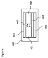
ここで、身体結合通信(BCC)装置アーキテクチャ400の実施形態を図示する図4を参照する。いくつかの実施形態において、BCC装置アーキテクチャ400は、BCC送受信器集積回路401、ホストプロセッサ402、電極403、並びにバッテリ及び電力管理モジュール404を備える。BCC送受信器集積回路401は、シリアルペリフェラルインタフェース405を介してホストプロセッサ402と通信する。電極403は身体と接触しており、信号を送受信するために使用される。バッテリ及び電力管理モジュール404は、BCC送受信器集積回路401及びホストプロセッサ402に接続される。
Here, reference is made to FIG. 4, which illustrates an embodiment of the body-coupling communication (BCC)
いくつかの実施形態において、ホストプロセッサ402は、BCC機能を使用して他のBCC対応センサ/装置と通信する装置の一部である。ホストプロセッサ402は(最初に)設定を構成し、そしてBCC集積回路送受信器401に、別のBCC装置に送信されることになる関連又は他のデータを渡す。BCC集積回路401は、データをパケット化して送るように構成される。BCC集積回路は、データパケットからデータを受信及び抽出するように構成される。ホストプロセッサ402は次いで、シリアルペリフェラルインタフェース(SPI)405を介してBCC集積回路401によって受信された抽出センサデータを読み取る。
In some embodiments, the
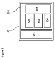
ここで、身体結合通信BCC送受信器集積回路401の一実施形態を図示する図5を参照する。いくつかの実施形態において、BCC送受信器集積回路401は、アナログフロントエンド(AFE)501及びデジタルサブシステム502を備える。デジタルサブシステム502は、ホストインタフェース制御論理503、システム制御論理504、受信論理505及び送信論理506を備える。AFE501は、電極403を駆動するためのインタフェーシング及びバッファリング、送信集積回路レベルのエンコーディング及びデコーディング、ローカルクロック同期、入力信号増幅などを扱う。デジタルサブシステム502は、送受信パケット処理、システム制御及びホストプロセッサインタフェーシングなどの機能を扱う。
Here, reference is made to FIG. 5, which illustrates an embodiment of the body-coupled communication BCC transmitter / receiver integrated
BCC受信器は、できる限り正確にパケット開始(SOP)を検出するべきである。典型的に、SOPが大きいほど、検出の精度は高くなる。いくつかの実施形態は、64/128ビットであるSOPを使用する。しかしながら、これは例としてであり、SOPのためにより小さい又はより大きいビット長が使用されてもよい。SOPは、同期目的で使用される1000ビットのプリアンブルによって先行される。プリアンブルは代替的に、このビット数より大きく又は小さくできる。例えば、プリアンブルは、100クロックサイクルより少なく又は多くできる。雑音の結果として、受信器は破損メッセージパケットを取り上げる。受信器は、したがって、SOPパケットにおける破損ビットの存在にもかかわらずSOPパケットを正確に解釈することができなければならない。SOP検出器が許容することができ、なお且つSOPパケットを正確に解釈することができる破損ビット数は、「閾値」又は「耐雑音性レベル」と呼ばれる。設定することができる閾値を有することは、システムが、主要オーバーホールの必要なしに1つの使用法から別の使用法に有利に適合されることを意味する。 BCC receivers should detect packet start (SOP) as accurately as possible. Typically, the higher the SOP, the higher the accuracy of detection. Some embodiments use SOP, which is 64/128 bits. However, this is an example, and smaller or larger bit lengths may be used for SOP. The SOP is preceded by a 1000-bit preamble used for synchronization purposes. The preamble can optionally be greater than or less than this number of bits. For example, the preamble can be less or more than 100 clock cycles. As a result of the noise, the receiver picks up the corrupted message packet. The receiver must therefore be able to correctly interpret the SOP packet despite the presence of corrupted bits in the SOP packet. The number of corrupted bits that the SOP detector can tolerate and still correctly interpret the SOP packet is called the "threshold" or "noise resistance level". Having a threshold that can be set means that the system is advantageously adapted from one usage to another without the need for a major overhaul.
実施形態において、受信器によって活用されることになる閾値は動的に設定される。有効な閾値が雑音に依存する一方、システムにおける実際の雑音レベルは演繹的に知られていない。実際の雑音(より高い又はより低い)と一致しない閾値レベルは正確な検出を低減させる。したがって、いくつかの実施形態は、雑音レベルに依存して設定することができる閾値を有するパケット開始検出器を提供する。 In embodiments, the thresholds that will be utilized by the receiver are dynamically set. The actual noise level in the system is deductively unknown, while the effective threshold depends on the noise. Threshold levels that do not match the actual noise (higher or lower) reduce accurate detection. Therefore, some embodiments provide a packet start detector with a threshold that can be set depending on the noise level.
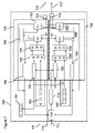
ここで、パケット開始検出器の実施形態を図示する図7を参照する。ブロックの1つ又は複数が専用ハードウェアで実装される。代替的に又は追加的に、1つ又は複数の機能がソフトウェアによって実装される。例えば、汎用ハードウェアが専用ソフトウェアを使用してこの機能を行う。いくつかの実施形態は、ハードウェアもソフトウェアも使用して実装される。以下の例では、8ビットレジスタなどが使用される。8ビットが単に例としてであり、他の実施形態がNビットレジスタなどとともに使用され、ここでNが適切な整数であることが認識されるべきである。パケット開始検出器は、正常極性ブロック718及び反対極性ブロック720を有する。
Here, reference is made to FIG. 7, which illustrates an embodiment of the packet start detector. One or more blocks are implemented with dedicated hardware. Alternatively or additionally, one or more functions are implemented by the software. For example, general purpose hardware uses dedicated software to perform this function. Some embodiments are implemented using both hardware and software. In the following example, an 8-bit register or the like is used. It should be recognized that 8 bits is merely an example and other embodiments are used with N-bit registers and the like, where N is a suitable integer. The packet start detector has a
図7は入力信号701を図示しており、それは8ビットレジスタ702に入る。これが、受信されるパケット開始データである。レジスタ702は正常極性ブロック内にある。
FIG. 7 illustrates the
正常極性ブロック718が最初に記載されることになる。レジスタ702は8ビットXOR演算子703に出力を提供する。別に、基準SOP記憶域704(正常極性ブロック外)からの8ビットの記憶された基準SOPコードが8ビットXOR演算子703に提供される。いくつかの実施形態において、SOPの長さは8ビットより長い。いくつかの実施形態において、SOPはmXNビット長である。Nは上記した通りであり、整数である。ここで記載される例では、mは8である。しかしながら、これが単に例としてであることが認識されるべきである。
The
いくつかの実施形態が、SOPのビット数がmxNに等しくなく使用されることが認識されるべきである。 It should be recognized that some embodiments use SOP bits unequal to mxN.
基準パケット開始情報のどのそれぞれの部分集合が第1のステージによって使用されるかを制御するために、カウンタが設けられる。これは、基準パケット開始情報の各部分集合が正しい順序で使用されることを確実にする。他の実施形態において異なる論理が使用されることが認識されるべきである。基準パケット開始情報のそれぞれの部分集合と受信したパケット開始情報のそれぞれの部分集合との間で一致があればカウンタの値が変更される。カウンタはインクリメント又はデクリメントされる。このように、カウンタの所与の値が達成されると、SOPの全体が検査されたと判定されることができる。 A counter is provided to control which subset of the reference packet start information is used by the first stage. This ensures that each subset of the reference packet start information is used in the correct order. It should be recognized that different logics are used in other embodiments. If there is a match between each subset of the reference packet start information and each subset of the received packet start information, the value of the counter is changed. The counter is incremented or decremented. Thus, when a given value of the counter is achieved, it can be determined that the entire SOP has been inspected.
この実施形態において、バイトカウンタが設けられる。バイトカウンタ機能705が、基準SOP記憶域から得られる基準バイトを規定する。バイトカウンタは正常極性ブロックの外に設けられてもよい。バイトカウンタ機能は、後記することになるようにいくつかの機能ブロックによって表される。機能ブロック705はバイトカウンタの現在値を提供する。これは、XOR機能703への入力のために基準SOP記憶域から基準SOPバイトのどのバイトが検索されるかを制御する。バイトカウンタが、例えば、値1を有するとき、SOP基準記憶域から第1バイトが検索される。
In this embodiment, a byte counter is provided. The
第1バイトがレジスタ702から読み出されるにつれて、受信したSOPの次のバイトが読み込まれることが認識されるべきである。クロックカウンタ機能が設けられる。クロックカウンタ機能は、後記することになるようにいくつかの機能ブロックによって表される。このクロックカウンタは、バイトカウンタによってリセットされない限り、8までカウントする。これは、より詳細に後記される。
It should be recognized that as the first byte is read from
第1のステージはしたがって、受信したパケット開始情報部分集合とそれぞれの基準パケット開始情報部分集合との間でそれぞれの排他的論理和を行うように構成された排他的論理和機能を含む。排他的論理和機能は有利には、基準及び受信値が同じであるときに1つの値を、そして基準及び受信値が異なるときに異なる値を提供することになる。 The first stage therefore includes an exclusive OR function configured to perform an exclusive OR between the received packet start information subset and each reference packet start information subset. The exclusive OR function will advantageously provide one value when the reference and received values are the same, and different values when the reference and received values are different.
XOR演算子は、基準SOPバイトをSOPバイトの受信したバイトと効果的に比較する。8ビットXOR演算子703の出力は、バイトカウンタ705の入力が0であり且つ8ビットレジスタ702の入力が1である場合に1を生成することになり、その逆も同じである(受信したSOP値とそれぞれの基準SOP値との間の不一致を示す)。しかしながら入力が両方とも0であれば、又は両入力が1であれば(受信したSOP値とそれぞれの基準SOP値との間の一致を示す)、8ビットXOR演算子703の出力は0を生成することになる。XOR演算子703はしたがって、基準SOPと受信したSOPデータを比較して、一致があるかどうかを判定する。一致したビットは0値出力を提供することになる。
The XOR operator effectively compares the reference SOP byte with the received byte of the SOP byte. The output of the 8-
第1のステージは、排他的論理和機能の出力を加算して合計した出力を、第1の比較器に提供するように構成された加算器機能を含み、第1の比較器は、上記合計した出力を閾値と比較するように構成される。有利には、排他的論理和機能の出力を合計することによって、基準及び受信したパケット開始情報間の一致の程度を示すことになる値が得られる。この値を閾値と比較することによって、情報のそれぞれの部分集合が一致であると考えられるか否かが簡単に判定されることができる。 The first stage includes an adder function configured to provide the first comparator with the sum of the outputs of the exclusive OR functions, the first comparator being the sum of the above. The output is configured to be compared with the threshold. Advantageously, by summing the outputs of the exclusive-OR function, a value that will indicate the degree of matching between the reference and the received packet start information is obtained. By comparing this value with the threshold, it can be easily determined whether or not each subset of the information is considered to be a match.
1つの実施形態において、XOR演算子703の8ビット出力は次いで8ビットADD演算子706に渡される。このADD演算子は、XOR演算子からの8値出力を合計することになる。8ビットADD演算子706は和を、受け取った和を閾値入力719によって設定される第1の閾値と比較する比較器707に提供する。
In one embodiment, the 8-bit output of the
第1のステージはしたがって、一致があるかどうかを判定するために閾値を使用するように構成されており、閾値が各部分集合に対して設定可能である。これは、閾値が、例えば雑音レベルに応じて変更されることを可能にする。 The first stage is therefore configured to use a threshold to determine if there is a match, and the threshold can be set for each subset. This allows the threshold to be changed, for example, depending on the noise level.
いくつかの実施形態において、閾値入力はバイトごとに変更されることができる。他の実施形態において、閾値入力はSOPごとに変更されることができる。他の実施形態において、閾値は制御される。いくつかの実施形態において、閾値は可変ではない。閾値は、いくつかの実施形態において、許容されることができ、なお且つ一致を提供することができる雑音量を決定することになる。 In some embodiments, the threshold input can be changed byte by byte. In other embodiments, the threshold input can be changed on a per SOP basis. In other embodiments, the threshold is controlled. In some embodiments, the threshold is not variable. The threshold will, in some embodiments, determine the amount of noise that can be tolerated and yet can provide a match.
パケット開始検出器は、パケット開始の全ての部分集合が一致と判定されたかどうかを判定し、そうであれば出力部によってパケット開始検出出力が出力されるようにするための第2の比較器を備える。 The packet start detector determines if all subsets of the packet start have been determined to match, and if so, a second comparator to ensure that the output unit outputs the packet start detection output. Be prepared.
ADD演算子706からの和が閾値以下であれば、機能ブロック708によって表されるように、バイトカウンタの値を1の値だけ増加させる出力が提供される。これは、信号のアサーションによって又は任意の他の適切なやり方であってもよく、また第2の比較器を介してであってもよい。出力は、第2の比較器713が、更新したバイトカウンタをm(この例では8)の値と比較して、SOPのバイトの全てがそれぞれの基準SOPと比較されたかどうかを判定するようにする。そうでなければ、第2の比較器の出力は、バイトカウンタが1だけインクリメントするようにすることになる。言い換えれば、基準及び受信したSOP間で一致があると思われ、且つ比較されたバイト数が最大量より少ないとの条件で、バイトカウンタがインクリメントされることになる。
If the sum from the
和が閾値より大きければ、機能709によって表される第1の比較器707の出力は、バイトカウンタをインクリメントしない。この出力は、機能ブロック712によって表されるように、クロックカウントを1だけインクリメントすることになるクロックカウンタ機能710に提供される。これは、より詳細に後記される。他の実施形態において、カウンタが代わりにデクリメントされてもよいことが認識されるべきである。
If the sum is greater than the threshold, the output of the
第1のステージは、パケット開始情報の全ての部分集合が一致すると判定されれば、出力部によってパケット開始検出出力が出力されるように構成される。これは、いずれかのそれぞれの部分集合が一致しなければ、一致がないと考えられるという点で実装するのが簡単である。 The first stage is configured so that the output unit outputs a packet start detection output if it is determined that all the subsets of the packet start information match. This is easy to implement in that if any subset of each does not match, then it is considered non-matching.
パケット開始検出器は、第1のステージと並列に配置される第2のステージであって、受信したパケット開始情報のそれぞれの部分集合を基準パケット開始情報のそれぞれの部分集合の反転と比較するように構成された第2のステージを備える。これは、共通接地を有する装置に関して有用である。検出器はしたがって、受信したメッセージを反対極性であると解釈する(すなわち2進数の1は0と解釈され、その逆も同じである)。したがって、第2のステージを有することによって、SOP検出器は両方の可能な極性を考慮することができる。 The packet start detector is a second stage arranged in parallel with the first stage so that each subset of the received packet start information is compared with the inversion of each subset of the reference packet start information. It is equipped with a second stage configured in. This is useful for devices with a common ground. The detector therefore interprets the received message as having opposite polarity (ie, the binary number 1 is interpreted as 0 and vice versa). Therefore, by having a second stage, the SOP detector can take into account both possible polarities.
BCC受信器及び送信器は典型的に共通接地を有さず、そのため基準電圧が存在しない。受信器はしたがって、受信したメッセージを反対極性であると解釈する(すなわち2進数の1は0と解釈され、その逆も同じである)。したがって、SOP検出器は、どちらの極性が受信されているかについて確信がないので、両方の可能な極性を考慮するべきである。前述したように、正常極性ブロック718及び反対極性ブロックがある。 BCC receivers and transmitters typically do not have a common ground, so there is no reference voltage. The receiver therefore interprets the received message as having opposite polarity (ie, the binary number 1 is interpreted as 0 and vice versa). Therefore, the SOP detector is uncertain which polarity is being received and should consider both possible polarities. As mentioned above, there are normal polarity blocks 718 and opposite polarity blocks.
反対極性ブロックにおいて基準SOPの値を反転し、XOR演算子703’に反転した基準SOP値を出力するために、NOT機能721が設けられる。
A
反対極性ブロックは正常極性ブロックと同じ機能及びブロックを有するが、それらの機能及びブロックは同じ参照番号及び添え字として’で参照符がつけられる、例えば、703’である。 The opposite polarity block has the same function and block as the normal polarity block, but those functions and blocks are referenced by'with the same reference number and subscript, eg, 703'.
正常極性ブロックの第2の比較器の出力は、第1のORゲート714への入力として提供される。反対極性ブロックの第2の比較器の出力は、第1のORゲートへの第2の入力として提供される。第2の比較器の出力のいずれかが、SOPの全てのバイトが比較されたことを示すとき、ORゲートの出力はハイであり同期出力715を提供することになる。これは、受信データのSOPが受信されたことを示す。
The output of the second comparator of the normal polarity block is provided as an input to the first OR
出力部は、パケット開始検出出力が第1のステージ又は第2のステージの上記判定することに依存しているかを示す情報を出力するように構成される。いくつかの実施形態において、これは、パケットの内容を理解するために使用される。これは、回路がデータにおいて論理1を表すもの及び論理0を表すものを理解するのを可能にする。 The output unit is configured to output information indicating whether the packet start detection output depends on the determination of the first stage or the second stage. In some embodiments, this is used to understand the contents of the packet. This allows the circuit to understand what represents logic 1 and what represents logic 0 in the data.
第2のORゲート716も設けられる。このORゲートの出力は、第1のORゲートによって同期出力が提供されるときに、SOPが正常極性SOPブロック又は反対極性SOPブロックによって一致されたかを判定するために使用される。したがって、正常極性ブロックの第2の比較器713が全てのバイトが比較されたと判定すると、正常極性ブロックの第2の比較器713は第2のORゲート716に0を出力することになる。反対極性ブロックの第2の比較器713’が全てのSOPバイトが比較されたと判定すると、反対極性ブロックの第2の比較器713’は第2のORゲート716に1を出力することになる。したがって、第2のORゲートの出力は極性情報717を提供する。
A second OR
値は次いで、正常極性ブロック718におけるバイトカウンタブロック705及び反対極性ブロック720におけるバイトカウンタブロック705’に渡される。値が機能ブロック708に渡され、そしてバイトカウンタ705が1の値だけ増加されれば、値は次いで第2の閾値演算子713に渡され、ここで値が第2の閾値演算子713の値以下であれば、値はOR演算子714に渡され、最終的に正常出力715を形成する。しかしながら、値が第2の閾値演算子713の値以下であれば、値はOR演算子716に渡され、最終的に反対極性出力717を形成する。これらのステップは正常極性ブロック718で行われる。反対極性ブロック720も存在し、反対極性であるビットを除けば、以上に開示したのと同一組のステップを有する。
The values are then passed to the
いくつかの実施形態において、受信したSOPパケット300は8ビットセグメントに分割される。SOP検出成功のためには、受信したビットにおいて8バイトが連続して検出されなければならない。例えば、2つの8ビットレジスタ702及び702’は、正常極性ブロック718のレジスタ702における各ビットをゼロに設定する(0x00)ことによって及び反対極性ブロック720のレジスタ702’における各ビットを1に設定する(0xFF)ことによって初期化される。反対極性ブロック720のレジスタ702’は、反対極性ブロック720のSOPの前のコード(例えばプリアンブル)が8つのゼロで始まり、そのため各ビットをゼロに設定することによってレジスタを初期化することは第1バイトに対する誤った一致を引き起こすので、各ビットを1に設定することによって初期化される。反対極性ブロックのためのシフトレジスタは、誤った第1バイト一致を防止するために、残りのプリアンブルビット数が8より小さいときに必要とされる。より大きなビット数に関しては、1つだけで十分であるように、両シフトレジスタは等しい値を有する。
In some embodiments, the received
いくつかの実施形態において、受信したビットは、クロックサイクルごとに8ビットレジスタ702及び702’にシフトされる。第1のステージを示すゼロの初期値から始まって、現在の比較が行われるべきであるステージ数をカウントするために、クロックカウンタが使用される。各ステージは、ゼロに初期化されてSOPの第1バイトを示すバイトカウンタに8ビット一致成功のそれ自身の履歴を保存する。
In some embodiments, the received bits are shifted to the 8-
例えば、第1クロックサイクルに対する正常極性ブロック718において、クロックカウンタの初期値(ゼロ)はアルゴリズムの第1のステージを示す。第1の受信したビット701が8ビットレジスタ702(反対極性ブロック720ではレジスタ702’)の第1の(最下位ビット)位置にシフトされることになる一方、その他のビットは位置1つだけ上へ(最上位ビット位置に向けて)シフトされる。レジスタ702の8ビットは次いで、SOPのb番目のセグメントと比較され、ここでbの値はバイトカウンタによって示される。初期値が第1バイトを示すので、比較のために第1基準SOPバイトが使用される。比較が閾値限界より低い誤差を生じれば、バイトカウンタはインクリメント又はその他リセットされる。
For example, in the
第2のクロックサイクルでは、次の受信したビットがレジスタ702(反対極性ブロック720ではレジスタ702’)にシフトされ、そしてクロックカウンタが1だけインクリメントされる。ここで、アルゴリズムの第2のステージは、そのバイトカウンタ値(再び最初にゼロである)を比較することによって実行され、それに応じてバイトカウンタを更新する。これが全ての8つのステージに対して続く。8クロックサイクル後に、第1のステージが再び実行されるように、クロックカウンタ712はゼロにリセットされる。しかしながら今回は、レジスタ702(反対極性ブロック720ではレジスタ702’)の8ビットは基準SOPの第2バイトと比較され(前回のバイトが一致である場合)、それに応じてバイトカウンタが更新される。SOPの全ての8バイト又はセグメントが連続して検出されるまでこの工程が繰り返され、次いで同期信号715がハイ状態に設定される。同様の動作が反対極性ブロック720において続き、相違点は検索したSOPセグメントが比較前に反転される(NOT721)ことである。SOPが検出されたブロックに基づいて、極性情報が生成される。
In the second clock cycle, the next received bit is shifted to register 702 (register 702'in opposite polarity block 720) and the clock counter is incremented by 1. Here, the second stage of the algorithm is performed by comparing its byte counter values (again, initially zero), updating the byte counters accordingly. This continues for all eight stages. After eight clock cycles, the
いくつかの実施形態は比較的長いSOP、例えば64ビット又は128ビットとともに使用される。これは単に例としてであり、異なる実施形態において、異なる長さのSOPが使用される。 Some embodiments are used with relatively long SOPs such as 64-bit or 128-bit. This is merely an example, and different lengths of SOP are used in different embodiments.
SOPの実装が通信リンクの質を規定しており、それは、使用されるプロトコル、ビットレート、データ処理能力、再送信、雑音レベルなどといった1つ又は複数の態様に依存する。 The implementation of SOP defines the quality of the communication link, which depends on one or more aspects such as protocol used, bit rate, data processing power, retransmission, noise level, and the like.
本実施形態において、8ステージ、8ビット相関器が図示されており、Nステージがnビットとともに使用され得ることが認識されるべきである。例えば、本実施形態は、64ビットSOPに対して8ステージ、8ビット半並列検出手法を活用する。例えば、別の実施形態は、128ビットSOPに対して16ステージ、16ビット半並列検出手法を活用する。さらに、様々なステージ数(Nステージ)が様々なビット数(nビット)とともに使用され得ることが認識されるべきである。 In this embodiment, an 8-stage, 8-bit correlator is illustrated and it should be recognized that the N-stage can be used with n-bits. For example, this embodiment utilizes an 8-stage, 8-bit semi-parallel detection method for a 64-bit SOP. For example, another embodiment utilizes a 16-stage, 16-bit semi-parallel detection method for a 128-bit SOP. Furthermore, it should be recognized that different numbers of stages (N stages) can be used with different numbers of bits (n bits).
いくつかの実施形態において、耐雑音性レベル(閾値)はバイトごとに適用される。いくつかの実施形態は、SOPパケット長にかかわりなく低コスト8ビットXOR及びADDユニットの再利用を可能にする。これは、削減された(例えば2倍)物理的面積及び電力消費に至る。いくつかの実施形態においてバイトごとに雑音閾値を有することは、雑音レベルのより大きな変化にわたる高い割合の正確な検出を提供する固定最適閾値レベルを可能にする。 In some embodiments, the noise immunity level (threshold) is applied byte by byte. Some embodiments allow low cost 8-bit XOR and ADD unit reuse regardless of SOP packet length. This leads to reduced (eg, double) physical area and power consumption. Having a noise threshold per byte in some embodiments allows for a fixed optimal threshold level that provides a high percentage of accurate detection over larger changes in noise level.
いくつかの実施形態において、バイトごとの閾値条件が緩和される。比較されるバイトの例えば1つだけが閾値限界を超えることができてもよい。閾値限界を超えることができるバイト数は設計選択である。いくつかの実施形態において、これはSOPにおけるバイト数に依存している。いくつかの実施形態において、適用可能な閾値は一次バイト閾値より例えば1つ大きい。例えば、一次閾値がバイトごとに3であれば、欠陥バイトは4の閾値を満たさなければならない。SOPが例えば8バイトであれば、これはバイトの1つが閾値を満たすことができなくとも、依然SOPが検出されるのを可能にする。与えられる値が単に例としてであり、異なる実施形態において異なることが認識されるべきである。閾値実装は、バイト当たり所与の数を超えるビットが破損したときにフラグを与える論理を使用する。その場合、バイト全体が破損したと考えられる。閾値論理は、パケット全体が放棄される前に何個の破損バイトが認められるかを決定する。 In some embodiments, the byte-by-byte threshold condition is relaxed. For example, only one of the bytes being compared may be able to exceed the threshold limit. The number of bytes that can exceed the threshold limit is a design choice. In some embodiments, this depends on the number of bytes in the SOP. In some embodiments, the applicable threshold is, for example, one greater than the primary byte threshold. For example, if the primary threshold is 3 per byte, the defective byte must satisfy the threshold of 4. If the SOP is, for example, 8 bytes, this allows the SOP to still be detected even if one of the bytes fails to meet the threshold. It should be recognized that the values given are merely examples and are different in different embodiments. The threshold implementation uses the logic of flagging when more than a given number of bits per byte are corrupted. In that case, the entire byte is considered to be damaged. Threshold logic determines how many corrupted bytes are allowed before the entire packet is abandoned.
記載した実施形態において、論理機能の種類の例は、例えばXOR及びORである。これらは単に例としてであり、異なる実施形態が異なる論理機能を有する。 In the described embodiments, examples of types of logical functions are, for example, XOR and OR. These are merely examples, and different embodiments have different logical functions.
記載した実施形態において、1及び0の値は特定の条件を示す。例えば、「1」は同期を示す。しかしながら、これが例としてであり、他の実施形態において他の「0」及び「1」が使用されることが認識されるべきである。 In the embodiments described, the values 1 and 0 indicate specific conditions. For example, "1" indicates synchronization. However, this is an example and it should be recognized that the other "0" and "1" are used in other embodiments.
記載した実施形態において、加算器機能が使用されたが、これは単に例としてである。異なる実施形態において、異なる機能が使用される。 In the embodiments described, the adder function was used, but this is merely an example. In different embodiments, different functions are used.
代替実施形態において、パケット開始検出器は、IEEE規格:IEEE802.11b/g/n(WiFi)及びIEEE802.15(ブルートゥース(登録商標))に応じたものなどのSOP検出器を使用する任意の適切なデジタル通信システムのために提供される。他の実施形態は、IEEE 802.15.4又は他の適切な低レートワイヤレスパーソナルエリアネットワークとともに使用される。 In an alternative embodiment, the packet start detector is any suitable using a SOP detector such as one according to the IEEE standards: IEEE802.11b / g / n (WiFi) and IEEE802.15 (Bluetooth®). Provided for digital communication systems. Other embodiments are used with IEEE 802.15.4 or other suitable low rate wireless personal area networks.
いくつかの実施形態がデジタル領域でSOP検出を使用することが認識されるべきである。 It should be recognized that some embodiments use SOP detection in the digital domain.
いくつかの実施形態において、複雑な自動閾値調節論理の必要なしに閾値がユーザによって簡単に特定されることが認識されるべきである。 It should be recognized that in some embodiments, the threshold is easily identified by the user without the need for complex automatic threshold adjustment logic.
いくつかの実施形態は、エンコードされもしないし、広がり機能を使用して拡散されもしないSOPを検出するために、単純な直接相関ベースの手法を使用する。 Some embodiments use a simple direct correlation-based approach to detect SOPs that are neither encoded nor spread using the spread function.
1つの変形例において、受信したSOPの一部と基準SOPとの間の各比較に対して値が記憶される。値は、一致があれば1つの値を、そうでなければ異なる値を有することになる。SOPの全てが基準SOPと比較されたとき、値は、SOP全体が基準値と一致すると考えられるかどうかを判定するために使用される。これは、各比較に対する値が1つの値を有することを必要とする。他の実施形態において、1つの値を有することを必要とされる値の閾値数がある。 In one variant, a value is stored for each comparison between a portion of the received SOP and the reference SOP. The values will have one value if there is a match, and different values otherwise. When all of the SOPs are compared to the reference SOP, the values are used to determine if the entire SOP is considered to match the reference values. This requires that the value for each comparison have one value. In other embodiments, there is a threshold number of values that are required to have one value.
別の変形例において、各比較に対する値は前回の比較値と累算される。累積値は、一致があるかどうかを判定するために閾値と比較される。 In another variant, the value for each comparison is cumulative with the previous comparison value. The cumulative value is compared to the threshold to determine if there is a match.
上記した構成が、集積回路、チップセット、共に若しくは異なるパッケージにパッケージ化される1つ若しくは複数のダイ、個別の回路、又はこれらのオプションの任意の組合せによって少なくとも部分的に実装されることが認識されるべきである。 Recognized that the above configuration is at least partially implemented by integrated circuits, chipsets, one or more dies packaged together or in different packages, individual circuits, or any combination of these options. It should be.
いくつかの実施形態の方法を図示する図8を参照する。ステップS1では、受信したパケット開始情報の第1の部分集合が受け取られる。 See FIG. 8, which illustrates the methods of some embodiments. In step S1, the first subset of received packet start information is received.
ステップS2では、受信SOP情報の受け取った第1の部分集合が基準SOP情報のそれぞれの第1の部分集合と比較される。 In step S2, the received first subset of the received SOP information is compared with each first subset of the reference SOP information.
ステップS3では、基準SOP情報の第1の部分集合と受信SOP情報の対応する第1の部分集合との間で一致があるかどうかが判定される。いくつかの実施形態において、一致があるか否かに関する情報が記憶される。 In step S3, it is determined whether there is a match between the first subset of the reference SOP information and the corresponding first subset of the received SOP information. In some embodiments, information about whether or not there is a match is stored.
ステップS4では、受信SOP情報の別の部分集合があるかどうかが判定される。そうであれば、次のステップはステップS5である。 In step S4, it is determined whether there is another subset of the received SOP information. If so, the next step is step S5.
ステップS5では、受信SOP情報の次の部分集合が受け取られる。 In step S5, the next subset of received SOP information is received.
ステップS6では、受信SOP情報の次の部分集合が基準SOP情報のそれぞれの部分集合と比較される。 In step S6, the next subset of received SOP information is compared to each subset of reference SOP information.
ステップS7では、情報のそれぞれの基準SOP部分集合と情報の受信SOP部分集合との間で一致があるかどうかが判定される。方法は次いでステップS4にループして戻る。 In step S7, it is determined whether there is a match between each reference SOP subset of the information and the received SOP subset of the information. The method then loops back to step S4.
受信SOP情報の部分集合がもうないことがステップS4で判定されれば、次のステップはステップS8である。ステップS8では、比較の全てが一致すれば、検出SOP出力が提供される。したがって、受け取ったSOP情報の部分集合の全てがそれぞれの基準SOP情報と一致すれば、SOPが検出されたことを示す出力が提供される。 If it is determined in step S4 that the subset of received SOP information is no longer present, the next step is step S8. In step S8, if all of the comparisons match, a detection SOP output is provided. Therefore, if all of the subsets of the received SOP information match the respective reference SOP information, an output indicating that the SOP has been detected is provided.
一致があるか否かを判定するときに(ステップS3及びS7)、それぞれの閾値が設けられることが認識されるべきである。これは前記した通りである。 It should be recognized that each threshold is set when determining if there is a match (steps S3 and S7). This is as described above.
異なる変形をもつ様々な実施形態が、ここに上記された。当業者がこれらの様々な実施形態及び変形の様々な要素を組み合わせてもよいことが留意されるべきである。 Various embodiments with different variants are described herein. It should be noted that one of ordinary skill in the art may combine various elements of these various embodiments and variants.
そのような変更、変形及び改善は本開示の一部であるものと意図され、且つ本発明の範囲内であるものと意図される。したがって、上記の説明は単に例としてであり、限定的であるものとは意図されない。本発明は以下の請求項及びその等価物で定められるように限定されるのみである。 Such changes, modifications and improvements are intended to be part of this disclosure and are intended to be within the scope of the present invention. Therefore, the above description is merely an example and is not intended to be limiting. The present invention is limited only as set forth in the following claims and their equivalents.
Claims (11)
基準パケット開始情報のそれぞれの部分集合と受信した前記パケット開始情報のそれぞれの部分集合との間で一致があるかどうかを判定する第1のステージであって、受信した前記パケット開始情報の部分集合の各々及び前記基準パケット開始情報の前記それぞれの部分集合に対して前記判定することを繰り返し、前記基準パケット開始情報の前記それぞれの部分集合と受信した前記パケット開始情報の前記それぞれの部分集合との間で一致があればカウンタの値が変更される第1のステージと、
前記第1のステージと並列に配置される第2のステージであって、受信した前記パケット開始情報の前記それぞれの部分集合を前記基準パケット開始情報の前記それぞれの部分集合の反転と比較する第2のステージと、
前記第2のステージ又は前記第1のステージの判定に依存してパケット開始検出出力を提供する出力部であって、前記カウンタの前記値と閾値との比較に依存してパケット開始検出出力を提供する出力部とを備え、
前記出力部は、前記パケット開始検出出力が前記第1のステージの判定に依存しているか又は前記第2のステージの判定に依存しているかを示す情報を出力する、パケット開始検出器。 An input unit that receives input data including packet start information,
A first stage for determining whether there is a match between each subset of the reference packet start information and each subset of the received packet start information, which is a subset of the received packet start information. The determination is repeated for each of the above and the respective subsets of the reference packet start information, and the respective subsets of the reference packet start information and the respective subsets of the received packet start information are obtained. If there is a match between them, the value of the counter will be changed in the first stage, and
A second stage arranged in parallel with the first stage, wherein the respective subsets of the received packet start information are compared with the inversion of the respective subsets of the reference packet start information. Stage and
An output unit that provides a packet start detection output depending on the determination of the second stage or the first stage, and provides a packet start detection output depending on the comparison between the value of the counter and the threshold value. Equipped with an output unit
The output unit is a packet start detector that outputs information indicating whether the packet start detection output depends on the determination of the first stage or the determination of the second stage .
前記受信したパケット開始情報の前記第1の部分集合を基準のそれぞれの第1の部分集合と比較して、一致があるかどうかを判定する第1の判定を行うステップと、
前記受信したパケット開始情報の前記第1の部分集合を前記基準のそれぞれの前記第1の部分集合の反転と比較して、一致があるかどうかを判定する第2の判定を行うステップと、
一致が判定されればカウントの値を変更するステップと、
前記受信したパケット開始情報の後続の部分集合及び前記基準のパケット開始情報のそれぞれの部分集合に対して前記受け取るステップ及び比較するステップを繰り返すステップと、
前記カウントの前記値と閾値とを比較するステップに依存してパケット開始検出出力を提供するステップとを有し、
前記パケット開始検出出力を提供するステップは、前記パケット開始検出出力が前記第1の判定に依存しているか又は前記第2の判定に依存しているかを示す情報を出力するステップを含む、パケット開始を検出する方法。 The step of receiving the first subset of the received packet start information,
A step of comparing the first subset of the received packet start information with each first subset of the reference and performing a first determination to determine if there is a match.
A step of comparing the first subset of the received packet start information with the inversion of each of the first subsets of the reference and performing a second determination to determine if there is a match.
If a match is determined, the step to change the count value and
A step of repeating the receiving step and the comparing step for each subsequent subset of the received packet start information and each subset of the reference packet start information, and
It has a step of providing a packet start detection output depending on a step of comparing the value of the count with a threshold.
The step of providing the packet start detection output includes a step of outputting information indicating whether the packet start detection output depends on the first determination or the second determination. How to detect.
Applications Claiming Priority (3)
| Application Number | Priority Date | Filing Date | Title |
|---|---|---|---|
| EP16159293 | 2016-03-09 | ||
| EP16159293.6 | 2016-03-09 | ||
| PCT/EP2017/054263 WO2017153181A1 (en) | 2016-03-09 | 2017-02-24 | Method and apparatus for start-of-packet detection in digital communication systems |
Publications (4)
| Publication Number | Publication Date |
|---|---|
| JP2019508977A JP2019508977A (en) | 2019-03-28 |
| JP2019508977A5 JP2019508977A5 (en) | 2020-04-02 |
| JP7065780B2 JP7065780B2 (en) | 2022-05-12 |
| JP7065780B6 true JP7065780B6 (en) | 2022-06-06 |
Family
ID=55527325
Family Applications (1)
| Application Number | Title | Priority Date | Filing Date |
|---|---|---|---|
| JP2018546844A Active JP7065780B6 (en) | 2016-03-09 | 2017-02-24 | Methods and equipment for packet start detection in digital communication systems |
Country Status (5)
| Country | Link |
|---|---|
| US (1) | US10623113B2 (en) |
| EP (1) | EP3427415B1 (en) |
| JP (1) | JP7065780B6 (en) |
| CN (1) | CN108702224B (en) |
| WO (1) | WO2017153181A1 (en) |
Citations (3)
| Publication number | Priority date | Publication date | Assignee | Title |
|---|---|---|---|---|
| WO2009075420A1 (en) | 2007-12-13 | 2009-06-18 | Electronics And Telecommunications Research Institute | Human body communication system and communication method thereof |
| US20130003886A1 (en) | 2011-07-01 | 2013-01-03 | Electonics And Telecommunications Research Institute | Method for generating and detecting preamble, and digital communication system based on the same |
| JP2013051613A (en) | 2011-08-31 | 2013-03-14 | Kawasaki Microelectronics Inc | Reception apparatus |
Family Cites Families (28)
| Publication number | Priority date | Publication date | Assignee | Title |
|---|---|---|---|---|
| JPS6133040A (en) | 1984-07-26 | 1986-02-15 | Nec Corp | Detector for frame synchronizing pattern |
| JPH01160232A (en) * | 1987-12-17 | 1989-06-23 | Nec Corp | Correlation detecting circuit |
| KR950013805B1 (en) | 1991-12-23 | 1995-11-16 | 삼성전자주식회사 | Synchronous detecting circuit of digital signal |
| TW280068B (en) | 1995-03-14 | 1996-07-01 | Adaptive Networks Inc | Method and apparatus for data encoding and communication over noisy media |
| US7151759B1 (en) | 2001-03-19 | 2006-12-19 | Cisco Systems Wireless Networking (Australia) Pty Limited | Automatic gain control and low power start-of-packet detection for a wireless LAN receiver |
| KR100542039B1 (en) * | 2002-07-02 | 2006-01-10 | 삼성탈레스 주식회사 | Apparatus for generating frame sync signal in mobile communication device |
| US7062703B1 (en) | 2003-07-28 | 2006-06-13 | Cisco Technology, Inc | Early detection of false start-of-packet triggers in a wireless network node |
| US7809020B2 (en) | 2003-10-31 | 2010-10-05 | Cisco Technology, Inc. | Start of packet detection for multiple receiver combining and multiple input multiple output radio receivers |
| US7480234B1 (en) | 2003-10-31 | 2009-01-20 | Cisco Technology, Inc. | Initial timing estimation in a wireless network receiver |
| US7480282B2 (en) * | 2005-03-17 | 2009-01-20 | Agere Systems Inc. | Methods and apparatus for controlling ethernet packet transfers between clock domains |
| TWI309939B (en) * | 2006-01-06 | 2009-05-11 | Princeton Technology Corp | Packet preamble search method and device thereof |
| US8139582B2 (en) | 2007-05-17 | 2012-03-20 | Samsung Electronics Co., Ltd. | Method and apparatus for making transport frame and method and apparatus for processing transport frame |
| US8179920B2 (en) * | 2008-09-11 | 2012-05-15 | Entropic Communications, Inc. | High efficiency preambles for communications systems over pseudo-stationary communication channels |
| US8811547B2 (en) * | 2008-10-31 | 2014-08-19 | Koninklijke Philips N.V. | Wideband communication for body-coupled communication systems |
| EP2226002B1 (en) * | 2009-03-04 | 2012-01-18 | Fujitsu Limited | Improvements to body area networks |
| US20100287402A1 (en) * | 2009-05-11 | 2010-11-11 | Electronics And Telecommunications Research Institute | Timestamping apparatus and method |
| US20110085505A1 (en) * | 2009-10-12 | 2011-04-14 | Electronics And Telecommunications Research Institute | Method for producing communication frame of body area network and communication network of body area network using the same |
| US8989330B2 (en) * | 2010-07-30 | 2015-03-24 | Silicon Laboratories Inc. | Method and apparatus to detect a synchronization delimiter |
| JP5924880B2 (en) * | 2011-07-12 | 2016-05-25 | ラピスセミコンダクタ株式会社 | Data communication system, preamble length optimization method, and communication apparatus |
| KR20130104289A (en) * | 2012-03-13 | 2013-09-25 | 삼성전자주식회사 | Apparatus and method for estimating offset value, receiving apparatus, and method for processing signal in the same |
| EP2936709B1 (en) * | 2012-12-21 | 2019-06-05 | Koninklijke Philips N.V. | Electronic devices for, a system for and a method of controlling one of the electronic devices |
| KR20150004497A (en) * | 2013-07-02 | 2015-01-13 | 한국전자통신연구원 | Apparatus and method for transmitting of tag and apparatus for receiving of reader |
| US9240816B2 (en) * | 2013-08-09 | 2016-01-19 | Samsung Electronics Co., Ltd. | Timing synchronization system and method of super regenerative receiver based on ultra low power communication |
| JP6261774B2 (en) * | 2014-05-27 | 2018-01-17 | コーニンクレッカ フィリップス エヌ ヴェKoninklijke Philips N.V. | Humanoid communication device with synchronization |
| US10313027B2 (en) | 2014-09-11 | 2019-06-04 | Koninklijke Philips N.V. | Wide band through-body ultrasonic communication system |
| US9898611B2 (en) * | 2015-03-30 | 2018-02-20 | Rockwell Automation Technologies, Inc. | Method and apparatus for scrambling a high speed data transmission |
| US10033491B2 (en) * | 2015-11-25 | 2018-07-24 | Electronics And Telecommunications Research Institute | Data transmission device for human body communication, preamble generation method thereof, and frame synchronization method thereof |
| US9967039B2 (en) * | 2015-12-17 | 2018-05-08 | Electronics And Telecommunications Research Institute | Transceiver for human body communication and wireless communication and operating method thereof |
-
2017
- 2017-02-24 JP JP2018546844A patent/JP7065780B6/en active Active
- 2017-02-24 EP EP17707265.9A patent/EP3427415B1/en active Active
- 2017-02-24 WO PCT/EP2017/054263 patent/WO2017153181A1/en active Application Filing
- 2017-02-24 US US16/082,994 patent/US10623113B2/en active Active
- 2017-02-24 CN CN201780015911.3A patent/CN108702224B/en active Active
Patent Citations (3)
| Publication number | Priority date | Publication date | Assignee | Title |
|---|---|---|---|---|
| WO2009075420A1 (en) | 2007-12-13 | 2009-06-18 | Electronics And Telecommunications Research Institute | Human body communication system and communication method thereof |
| US20130003886A1 (en) | 2011-07-01 | 2013-01-03 | Electonics And Telecommunications Research Institute | Method for generating and detecting preamble, and digital communication system based on the same |
| JP2013051613A (en) | 2011-08-31 | 2013-03-14 | Kawasaki Microelectronics Inc | Reception apparatus |
Also Published As
| Publication number | Publication date |
|---|---|
| JP7065780B2 (en) | 2022-05-12 |
| EP3427415A1 (en) | 2019-01-16 |
| US20190103924A1 (en) | 2019-04-04 |
| CN108702224A (en) | 2018-10-23 |
| EP3427415B1 (en) | 2020-05-27 |
| CN108702224B (en) | 2021-05-25 |
| US10623113B2 (en) | 2020-04-14 |
| JP2019508977A (en) | 2019-03-28 |
| WO2017153181A1 (en) | 2017-09-14 |
Similar Documents
| Publication | Publication Date | Title |
|---|---|---|
| US11071116B2 (en) | Coding/decoding method, apparatus, and device | |
| US9543981B2 (en) | CRC-based forward error correction circuitry and method | |
| Sachenko et al. | Increasing the data transmission robustness in WSN using the modified error correction codes on residue number system | |
| US20110022916A1 (en) | Method and system for saving power for packet re-transmission in an encrypted bluetooth low power link layer connection | |
| US8571021B2 (en) | Packet based data transmission with reduced data size | |
| US20140269666A1 (en) | Method and apparatus for efficient signaling of communication mode and delimiter information | |
| US10129371B2 (en) | Serial communication device and serial communication method | |
| KR101410947B1 (en) | Method and apparatus for indicating a temporary block flow using a piggybacked ack/nack field | |
| US8488648B2 (en) | Apparatus and method for symbol error correctable modulation and demodulation using frequency selective baseband | |
| US10938512B2 (en) | Correlation-based detection of encoded address in packet | |
| JP7065780B6 (en) | Methods and equipment for packet start detection in digital communication systems | |
| JP3217716B2 (en) | Wireless packet communication device | |
| US9450705B2 (en) | Method and apparatus for detecting frame delimiters in Ethernet passive optical networks with forward error correction | |
| CN102208963B (en) | Decoding method for determining rate-free codes through binary system | |
| US10705906B2 (en) | Apparatus and control method thereof | |
| WO2014074069A1 (en) | Radio communication devices, access points, method for controlling a radio communication device, and methods for controlling an access point | |
| JP2012124642A (en) | Receiving device, data transfer device, and program | |
| EP2285003B1 (en) | Correction of errors in a codeword | |
| US8699624B2 (en) | Receiving apparatus and data transmission apparatus | |
| US11750677B2 (en) | Data transmission framing | |
| CN109600196B (en) | Method, device and system for detecting frame boundary | |
| US7761769B1 (en) | Method and apparatus for using valid bits for erasure correction | |
| JPS62136939A (en) | Code reception system | |
| CN116982276A (en) | Method and apparatus for detecting partial Discontinuous Transmission (DTX) using bit reconstruction |
Legal Events
| Date | Code | Title | Description |
|---|---|---|---|
| A521 | Request for written amendment filed |
Free format text: JAPANESE INTERMEDIATE CODE: A523 Effective date: 20200221 |
|
| A621 | Written request for application examination |
Free format text: JAPANESE INTERMEDIATE CODE: A621 Effective date: 20200221 |
|
| A977 | Report on retrieval |
Free format text: JAPANESE INTERMEDIATE CODE: A971007 Effective date: 20210125 |
|
| A131 | Notification of reasons for refusal |
Free format text: JAPANESE INTERMEDIATE CODE: A131 Effective date: 20210205 |
|
| A601 | Written request for extension of time |
Free format text: JAPANESE INTERMEDIATE CODE: A601 Effective date: 20210422 |
|
| A521 | Request for written amendment filed |
Free format text: JAPANESE INTERMEDIATE CODE: A523 Effective date: 20210803 |
|
| A131 | Notification of reasons for refusal |
Free format text: JAPANESE INTERMEDIATE CODE: A131 Effective date: 20220105 |
|
| A521 | Request for written amendment filed |
Free format text: JAPANESE INTERMEDIATE CODE: A523 Effective date: 20220311 |
|
| TRDD | Decision of grant or rejection written | ||
| A01 | Written decision to grant a patent or to grant a registration (utility model) |
Free format text: JAPANESE INTERMEDIATE CODE: A01 Effective date: 20220328 |
|
| A61 | First payment of annual fees (during grant procedure) |
Free format text: JAPANESE INTERMEDIATE CODE: A61 Effective date: 20220426 |
|
| R150 | Certificate of patent or registration of utility model |
Ref document number: 7065780 Country of ref document: JP Free format text: JAPANESE INTERMEDIATE CODE: R150 |