JP7065594B2 - Image coding device and its control method, and program - Google Patents
Image coding device and its control method, and program Download PDFInfo
- Publication number
- JP7065594B2 JP7065594B2 JP2017236294A JP2017236294A JP7065594B2 JP 7065594 B2 JP7065594 B2 JP 7065594B2 JP 2017236294 A JP2017236294 A JP 2017236294A JP 2017236294 A JP2017236294 A JP 2017236294A JP 7065594 B2 JP7065594 B2 JP 7065594B2
- Authority
- JP
- Japan
- Prior art keywords
- value
- plane
- correction
- block
- quantization
- Prior art date
- Legal status (The legal status is an assumption and is not a legal conclusion. Google has not performed a legal analysis and makes no representation as to the accuracy of the status listed.)
- Active
Links
Images


Classifications
-
- H—ELECTRICITY
- H04—ELECTRIC COMMUNICATION TECHNIQUE
- H04N—PICTORIAL COMMUNICATION, e.g. TELEVISION
- H04N19/00—Methods or arrangements for coding, decoding, compressing or decompressing digital video signals
- H04N19/10—Methods or arrangements for coding, decoding, compressing or decompressing digital video signals using adaptive coding
- H04N19/102—Methods or arrangements for coding, decoding, compressing or decompressing digital video signals using adaptive coding characterised by the element, parameter or selection affected or controlled by the adaptive coding
- H04N19/124—Quantisation
-
- H—ELECTRICITY
- H04—ELECTRIC COMMUNICATION TECHNIQUE
- H04N—PICTORIAL COMMUNICATION, e.g. TELEVISION
- H04N19/00—Methods or arrangements for coding, decoding, compressing or decompressing digital video signals
- H04N19/10—Methods or arrangements for coding, decoding, compressing or decompressing digital video signals using adaptive coding
- H04N19/169—Methods or arrangements for coding, decoding, compressing or decompressing digital video signals using adaptive coding characterised by the coding unit, i.e. the structural portion or semantic portion of the video signal being the object or the subject of the adaptive coding
- H04N19/17—Methods or arrangements for coding, decoding, compressing or decompressing digital video signals using adaptive coding characterised by the coding unit, i.e. the structural portion or semantic portion of the video signal being the object or the subject of the adaptive coding the unit being an image region, e.g. an object
- H04N19/176—Methods or arrangements for coding, decoding, compressing or decompressing digital video signals using adaptive coding characterised by the coding unit, i.e. the structural portion or semantic portion of the video signal being the object or the subject of the adaptive coding the unit being an image region, e.g. an object the region being a block, e.g. a macroblock
-
- H—ELECTRICITY
- H04—ELECTRIC COMMUNICATION TECHNIQUE
- H04N—PICTORIAL COMMUNICATION, e.g. TELEVISION
- H04N19/00—Methods or arrangements for coding, decoding, compressing or decompressing digital video signals
- H04N19/10—Methods or arrangements for coding, decoding, compressing or decompressing digital video signals using adaptive coding
- H04N19/169—Methods or arrangements for coding, decoding, compressing or decompressing digital video signals using adaptive coding characterised by the coding unit, i.e. the structural portion or semantic portion of the video signal being the object or the subject of the adaptive coding
- H04N19/18—Methods or arrangements for coding, decoding, compressing or decompressing digital video signals using adaptive coding characterised by the coding unit, i.e. the structural portion or semantic portion of the video signal being the object or the subject of the adaptive coding the unit being a set of transform coefficients
-
- H—ELECTRICITY
- H04—ELECTRIC COMMUNICATION TECHNIQUE
- H04N—PICTORIAL COMMUNICATION, e.g. TELEVISION
- H04N19/00—Methods or arrangements for coding, decoding, compressing or decompressing digital video signals
- H04N19/10—Methods or arrangements for coding, decoding, compressing or decompressing digital video signals using adaptive coding
- H04N19/169—Methods or arrangements for coding, decoding, compressing or decompressing digital video signals using adaptive coding characterised by the coding unit, i.e. the structural portion or semantic portion of the video signal being the object or the subject of the adaptive coding
- H04N19/186—Methods or arrangements for coding, decoding, compressing or decompressing digital video signals using adaptive coding characterised by the coding unit, i.e. the structural portion or semantic portion of the video signal being the object or the subject of the adaptive coding the unit being a colour or a chrominance component
-
- H—ELECTRICITY
- H04—ELECTRIC COMMUNICATION TECHNIQUE
- H04N—PICTORIAL COMMUNICATION, e.g. TELEVISION
- H04N19/00—Methods or arrangements for coding, decoding, compressing or decompressing digital video signals
- H04N19/10—Methods or arrangements for coding, decoding, compressing or decompressing digital video signals using adaptive coding
- H04N19/169—Methods or arrangements for coding, decoding, compressing or decompressing digital video signals using adaptive coding characterised by the coding unit, i.e. the structural portion or semantic portion of the video signal being the object or the subject of the adaptive coding
- H04N19/1883—Methods or arrangements for coding, decoding, compressing or decompressing digital video signals using adaptive coding characterised by the coding unit, i.e. the structural portion or semantic portion of the video signal being the object or the subject of the adaptive coding the unit relating to sub-band structure, e.g. hierarchical level, directional tree, e.g. low-high [LH], high-low [HL], high-high [HH]
-
- H—ELECTRICITY
- H04—ELECTRIC COMMUNICATION TECHNIQUE
- H04N—PICTORIAL COMMUNICATION, e.g. TELEVISION
- H04N19/00—Methods or arrangements for coding, decoding, compressing or decompressing digital video signals
- H04N19/60—Methods or arrangements for coding, decoding, compressing or decompressing digital video signals using transform coding
- H04N19/63—Methods or arrangements for coding, decoding, compressing or decompressing digital video signals using transform coding using sub-band based transform, e.g. wavelets
-
- H—ELECTRICITY
- H04—ELECTRIC COMMUNICATION TECHNIQUE
- H04N—PICTORIAL COMMUNICATION, e.g. TELEVISION
- H04N19/00—Methods or arrangements for coding, decoding, compressing or decompressing digital video signals
- H04N19/65—Methods or arrangements for coding, decoding, compressing or decompressing digital video signals using error resilience
Landscapes
- Engineering & Computer Science (AREA)
- Multimedia (AREA)
- Signal Processing (AREA)
- Compression Or Coding Systems Of Tv Signals (AREA)
- Compression Of Band Width Or Redundancy In Fax (AREA)
Description
本発明は、動画像の符号化技術に関するものである。 The present invention relates to a moving image coding technique.
デジタルビデオカメラ等に代表される撮像装置では、撮像センサで得られた生の画像データ(RAW画像)はデベイヤー処理(或いはデモザイク処理とも呼ばれる)され、1つの輝度成分データと2つの色差成分データから成る信号に変換され、各信号についてノイズ除去、光学的な歪補正、画像の適正化などの所謂現像処理が行われる。そして、この現像処理された輝度信号及び色差信号は圧縮符号化して、記録媒体に記録されるのが一般的である。 In an image pickup device typified by a digital video camera or the like, raw image data (RAW image) obtained by an image pickup sensor is subjected to debayer processing (also called demosaic processing) from one luminance component data and two color difference component data. Each signal is subjected to so-called development processing such as noise removal, optical distortion correction, and image optimization. Then, the developed luminance signal and the color difference signal are generally compressed and encoded and recorded on a recording medium.
一方で、RAW画像を記録できる装置も存在する。RAW画像は、記録されるデータ量が膨大になるが、現像処理前の実質的に無加工の画像データであり、後になって高度な編集が可能である利点から、上級者が好んで使われる記録画像データの形式である。 On the other hand, there are also devices that can record RAW images. Although the amount of data to be recorded is enormous, RAW images are substantially unprocessed image data before development processing, and are preferred by advanced users because of the advantage that advanced editing is possible later. This is the format of recorded image data.
ただし、RAW画像は上記の通り、そのデータ量が膨大であるため、限りある記録媒体に記録するために圧縮させたい。しかしながら、撮影条件によっては、この圧縮によって画質劣化を招くことがある。 However, as described above, the amount of data in a RAW image is enormous, so we want to compress it for recording on a limited recording medium. However, depending on the shooting conditions, this compression may cause deterioration of image quality.
特許文献1には、視覚特性に応じて量子化係数を変更する適応量子化による符号化の構成が記載されている。しかしながら、視覚特性で量子化係数を変更する場合、補正個所の多い画像では、補正度合いが弱くする、もしくは符号量が制御出来なくなってしまう等の問題が発生する。 Patent Document 1 describes a configuration of coding by adaptive quantization in which the quantization coefficient is changed according to the visual characteristics. However, when the quantization coefficient is changed according to the visual characteristics, problems such as a weak correction degree or an uncontrollable code amount occur in an image having many correction points.
本発明はかかる問題に鑑みなされたものであり、目標符号量への符号量制御を行いながらも、画質劣化の抑制した符号化データを生成する技術を提供しようとするものである。 The present invention has been made in view of such a problem, and an object of the present invention is to provide a technique for generating coded data in which image quality deterioration is suppressed while controlling the code amount to a target code amount.
この課題を解決するため、例えば本発明の画像符号化装置は以下の構成を備える。すなわち、
動画像を符号化する画像符号化装置であって、
入力した動画像のフレームを、それぞれが単一の成分で構成される複数のプレーンに分離する分離手段と、
分離して得た前記複数のプレーンにおける着目プレーンをウェーブレット変換するウェーブレット変換手段と、
該ウェーブレット変換手段で得られた各サブバンドから、画像の同じ領域を表すブロックを順に抽出する抽出手段と、
量子化パラメータを用いて、前記ブロック毎にウェーブレット変換係数を量子化する量子化手段と、
該量子化手段による量子化後のウェーブレット変換係数を符号化する符号化手段とを有し、
前記量子化手段は、
前記ブロック毎に、当該ブロックの直流値及び交流値及び複数の補正パラメータとの対応関係とに基づいて、前記複数の補正パラメータの中から前記量子化パラメータを補正するための補正パラメータを選択する決定手段を含み、
前記決定手段で選択した補正パラメータで補正した量子化パラメータに従って、ウェーブレット変換係数を量子化し、
前記対応関係は、各補正パラメータを選択するために、直流値の閾値及び交流値の閾値を有しており、直流値及び交流値が小さいほど量子化パラメータが減少するように補正される減少補正パラメータが設定され、直流値及び交流値が大きいほど量子パラメータが増加するように補正される増加補正パラメータが設定されており、
前記決定手段は、
前記複数の補正パラメータの各補正パラメータが選択された回数に応じて前記対応関係を変更し、
前記減少補正パラメータが選択された回数が、予め設定された回数よりも大きい場合は、前記対応関係における直流値の閾値または交流値の閾値を小さい値に変更することを特徴とする。
In order to solve this problem, for example, the image coding apparatus of the present invention has the following configuration. That is,
An image coding device that encodes moving images.
A separation means that separates the input moving image frame into multiple planes, each of which is composed of a single component.
A wavelet transform means for wavelet transforming the planes of interest in the plurality of planes obtained separately,
An extraction means for sequentially extracting blocks representing the same region of an image from each subband obtained by the wavelet transform means,
A quantization means that quantizes the wavelet transform coefficient for each block using the quantization parameter.
It has a coding means for encoding the wavelet transform coefficient after the quantization by the quantization means.
The quantization means is
For each block, a determination to select a correction parameter for correcting the quantization parameter from the plurality of correction parameters based on the DC value and AC value of the block and the correspondence with the plurality of correction parameters. Including means
The wavelet transform coefficient is quantized according to the quantization parameter corrected by the correction parameter selected by the determination means .
The correspondence has a DC value threshold and an AC value threshold for selecting each correction parameter, and the reduction correction is corrected so that the smaller the DC value and the AC value, the smaller the quantization parameter. Parameters are set, and increase correction parameters are set so that the quantum parameters increase as the DC value and AC value increase.
The determination means is
The correspondence is changed according to the number of times each correction parameter of the plurality of correction parameters is selected.
When the number of times the reduction correction parameter is selected is larger than the number of times preset, the threshold value of the DC value or the threshold value of the AC value in the correspondence relationship is changed to a smaller value .
本発明によれば、目標符号量への符号量制御を行いながらも、画質劣化の抑制した符号化データを生成することが可能になる。 According to the present invention, it is possible to generate coded data in which image quality deterioration is suppressed while controlling the code amount to the target code amount.
以下添付図面に従って本発明に係る実施形態を詳細に説明する。 Hereinafter, embodiments according to the present invention will be described in detail with reference to the accompanying drawings.
[第1の実施形態]
図1は、第1の実施形態の画像符号化装置が適用する撮像装置100のブロック構成図である。
[First Embodiment]
FIG. 1 is a block configuration diagram of an
撮像装置100は、装置全体の制御を司る制御部150、及び、ユーザの指示操作を受け付ける操作部151を有する。制御部150は、例えばCPU及びCPUが実行するプログラムを格納したROM及びワークエリアとして使用されるRAMで構成される。そして、撮像装置100は、撮像光学部101、撮像センサ部102、センサ信号処理部103、現像部104、表示処理部105、表示部106、外部出力端子107、RAW圧縮部109、RAW伸長部110、バッファ111、記録部112を有する。
The
以下は、上記構成における記録時の処理の説明である。この処理は操作部151から記録が指示された場合における制御部150による制御下で行われるものである。
The following is a description of the processing at the time of recording in the above configuration. This process is performed under the control of the
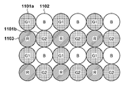
撮像対象となる被写体の光学像は、撮像光学部101を介して、撮像センサ部102上に結像する。撮像センサ部102は、赤、緑、青のカラーフィルタを前面に配置した2次元配列の多数の撮像素子で構成され、それぞれで得られた光の強度に応じた電気信号を生成する。そして、撮像センサ部102は、30フレーム/秒で撮像して得た画像の電気信号を出力する。実施形態における撮像センサ部102のカラーフィルタの配列は、図2に示すようになっている。この配列における2×2画素は、2つの緑(G1、G2)の画素(参照符号1101a,1101b)、1つの青(B)の画素(参照符号1102)、1つの赤(R)の画素(参照符号1103)で構成される。そして、この2×2の画素が周期的に配置されている。このような配列は一般にベイヤー配列と呼ばれる。
The optical image of the subject to be imaged is formed on the image
撮像センサ部102によって得られた電気信号は、センサ信号処理部103によってデジタルデータに変換され、画素の修復処理が施される。修復処理には、撮像センサ部102における欠落画素や信頼性の低い画素の値に対し、周辺画素値を用いて修復対象の画素を補間したり、所定のオフセット値を減算したりする処理が含まれる。本実施形態では、センサ信号処理部103から出力されるベイヤ配列の画像情報を、生(未現像)の画像を意味するRAW画像もしくはRAW画像データと称す。
The electric signal obtained by the image
現像部104は、センサ信号処理部103、或いは、後述するRAW伸長部110からのRAW画像に対し現像処理を行う。具合的には、現像部104は、RAW画像に対してデベイヤー処理(デモザイク処理)を施し、ホワイトバランス調整を行い、1画素が1つの輝度成分と2つの色差成分から成る信号に変換して、各信号に含まれるノイズを除去、光学的な歪を補正し、画像を適正化するなどの所謂現像処理を行う。そして、現像部104は現像後の画像データを表示処理部105に供給する。
The developing
表示処理部105は、現像部104からの画像データを、表示部106の解像度に応じてリサイズし、表示部106に出力し、画像を表示させる。表示処理部105は、現像処理された画像データを映像出力端子107により、外部に接続された表示機器に出力してもよい。映像出力端子107は、例えばHDMI(登録商標)やSDIのような汎用インタフェースである。
The
RAW圧縮部109は、センサ信号処理部103からのRAW画像を受信し、ウェーブレット変換や、差分符号化等の技術を用いて高能率符号化して符号化データを生成し、RAW画像データの符号化データとしてバッファ111に格納する。記録部112は、バッファに格納された符号化データを、RAW画像のファイルとして、記録媒体113に格納(保存)する。記録媒体113は、内蔵式の大容量メモリやハードディスク、又は、着脱式のメモリカードやネットワーク上の記録領域等であり、その種類は特に問わない。
The
次に、上記構成における再生時の処理を説明する。この処理は操作部151から再生が指示された場合における制御部150による制御下で行われるものである。
Next, the process at the time of reproduction in the above configuration will be described. This process is performed under the control of the
再生動作が開始されると、記録部112は、ユーザが指定したRAW画像の符号化データであるファイルを記録媒体113からバッファ111に読み出す。そして、RAW伸長部110は、バッファ111に読み出されたRAW画像の符号化データを伸長(復号)し、その結果であるRAW画像を現像部104に供給する。これ以降は、記録時と同じであり、伸長して得られRAW画像が表す画像が表示部106に表示される、又は外部出力端子107に接続された不図示の表示装置に表示されることになる。
When the reproduction operation is started, the
次に実施形態における特徴であるRAW圧縮部109の構造と処理について詳細に説明する。
Next, the structure and processing of the
図3は、実施形態におけるRAW圧縮部109のブロック構成図である。RAW圧縮部109は、プレーン分離部301、DWT(ウェーブレット変換)部302、バッファ303、ブロック抽出部304、量子化部305、エントロピー符号化部306、符号量算出部307、パラメータ処理部308、符号量制御部309を含む。
FIG. 3 is a block configuration diagram of the
プレーン分離部301は、センサ信号処理部103からのRAW画像を受信し、RAW画像を複数プレーンに分離する。具体的には、図4に示すように、プレーン分離部301は、RAW画像を、G1成分のみで構成されるG1プレーン、G2成分のみで構成されるG2プレーン、R成分のみで構成されるRプレーン、及び、B成分のみで構成されるBプレーンに分離する。RAW画像の水平方向画素数をW,垂直方向画素数をHとすると、これら4つのプレーンの各々は水平方向画素数W/2、垂直方向画素数H/2のサイズであり、各プレーンは、1画素1成分のモノクロ多値画像を表すものと言える。そして、プレーン分離部301は、分離処理で得られたG1プレーン、G2プレーン、Rプレーン、Bプレーンをその順にDWT部301に供給する。また、これ以降の処理は、G1プレーン、G2プレーン、Rプレーン、Bプレーンの種類を問わず、1つのプレーン、つまり、モノクロ多値画像としての符号化処理となる。また、以下では、符号化対象のプレーンを着目プレーンと称する。
The
DTW部302は、プレーン分離部301から供給された着目プレーン(G1プレーン、G2プレーン、Rプレーン、Bプレーンのいずれか)をモノクロ多値画像としてウェーブレット変換する。一般に、ウェーブレット変換は、前回の変換で得られたサブバンドLLに対して再帰的に適用できるが、実施形態では説明を単純化するため、ウェーブレット変換は1回だけ行うものとして説明する。図5は、1回のウェーブレット変換で得られるサブバンドLL,HL,LH,HHの位置関係を示している。DWT部302はウェーブレット変換を行って得た各サブバンド内の変換係数をバッファ303に格納する。
The
ブロック抽出部304は、バッファ303に格納されたサブバンドLL,HL,LH,HHから、予め設定されたm×n個(複数)の変換係数で構成されるブロック501乃至504をラスタースキャン順に抽出していく。そして、ブロック抽出部304は、抽出したブロック501乃至504を、量子化部305及びパラメータ処理部308に供給する。なお、当業者であればわかるように、ブロック501乃至504は、それぞれが属するサブバンドの種類は異なるものの、符号化対象の画像の同一領域のウェーブレット変換係数の集合を表す。また、以降、符号化しようとしているブロック501乃至504を着目ブロックと称する。
The
量子化部305は、ブロック抽出部から供給された着目ブロックの変換係数を、符号量制御部308から設定された量子化パラメータQで規定される量子化ステップを用いて量子化し、その結果をエントロピー符号化部306に供給する。
The
エントロピー符号化部306は、着目ブロックにおける量子化係数をエントロピー符号化し、生成された符号化データをバッファ111(図1参照)に出力する。また、エントロピー符号化部306は、着目ブロックから得られた符号化データの符号量を示す情報を符号量算出部307に供給する。なお、エントロピー符号化としては、ゴロム符号とするが、その種類は問わない。
The
符号量算出部307は、着目ブロックの直前のブロックまでに発生した符号化データの累積符号量と、直前のブロックの時点での目標符号量との差を算出し、その結果を符号量制御部308に供給する。
The code
1つのサブバンドに含まれるブロック数がNであるとする。また、制御部150から設定される1プレーンの目標符号量をTと表す。故に、1ブロック当たりの目標符号量は『T/N』と表せる。また、着目プレーンの第i番目のブロックをBiと表し、ブロックBiを符号化することで得られた符号化データの符号量をC(Bi)と表す。すると、そのブロックBiから生成された符号の符号量と、1ブロック当たりの目標符号量T/Nの差E(i)は以下のように表せる。
E(i)=C(Bi)-T/N
今、符号化しようとする着目ブロックが第i番目のブロックBkであるとする。つまり、先頭のブロックB1から直前のブロックBi-1までは、符号化が完了しているとする。この場合、符号量算出部307は、最初のブロックB1の差E(1)から、直前のブロックBi-1の差E(i-1)まで累積加算(合算)した値『ΣE(i-1)』(以下、累積符号量差)を求め、符号量制御部308に供給する。
ΣE(i-1)=Σ{C(Bk)-T/N}
又は
ΣE(i-1)=ΣC(Bk)-(i-1)×T/N
(但し、k=1、2、…、i-1)
パラメータ処理部308は、着目ブロックBiのウェーブレット変換係数に基づき、着目ブロック用の量子化パラメータを補正するための補正パラメータPxを算出し、符号量制御部309に設定する(詳細後述)。
It is assumed that the number of blocks included in one subband is N. Further, the target code amount of one plane set by the
E (i) = C (B i ) -T / N
Now, it is assumed that the block of interest to be encoded is the i-th block B k . That is, it is assumed that the coding is completed from the first block B 1 to the immediately preceding block B i-1 . In this case, the code
ΣE (i-1) = Σ {C (B k ) -T / N}
Or ΣE (i-1) = ΣC (B k )-(i-1) × T / N
(However, k = 1, 2, ..., i-1)
The
符号量制御部309は、次式に従って、着目ブロックBiの量子化パラメータQを決定し、量子化部305に設定する。
Q=Qini+r×ΣE(i-1)+Px …(1)
ここで、Qiniは初期量子化パラメータ、rは制御感度を示す係数であり、これらは共に制御部150より設定されるものである。感度rは、その値が大きいほど、量子化パラメータQの変動幅が大きくなり、符号量の制御が容易となる。反面、ブロック刊での量子化パラメータの差が大きくなりやすいので、ブロック間の画質の差となって現れる。
The code
Q = Q ini + r × ΣE (i-1) + Px… (1)
Here, Q ini is an initial quantization parameter, and r is a coefficient indicating control sensitivity, both of which are set by the
ここで、式(1)の補正パラメータPxが無い、或いはPx=0の場合について考察する。 Here, a case where there is no correction parameter Px in the equation (1) or Px = 0 will be considered.
図6(a)は、この場合の着目プレーンの符号化処理における符号量の推移を示すグラフである。水平軸がブロック数、垂直軸が符号量を表している。直線601は、y=i×T/Nを表している。直線601は、最終ブロックの位置のプレーンの目標符号量Tと原点とを結ぶ直線と言うこともできる。一方、曲線602は、実際に符号化処理していく過程での累積符号量を表している。具体的には、y=ΣC(Bi)を表している。
FIG. 6A is a graph showing the transition of the code amount in the coding process of the plane of interest in this case. The horizontal axis represents the number of blocks, and the vertical axis represents the amount of code. The
図示の如く、直前のブロックBi-1の時点での累積符号量が、直線601を上回った場合、式(1)に従って着目ブロックBi用の量子化パラメータQは、より大きな値に更新される。故に、着目ブロックBiにおける量子化後の変換係数の値は小さくなり易くなり、結果、着目ブロックBiの符号量を少なくなる傾向に制御できる。
As shown in the figure, when the cumulative code amount at the time of the immediately preceding block B i-1 exceeds the
一方、直前のブロックBi-1の時点での累積符号量が、直線601を下回った場合、式(1)に従って着目ブロックBi用の量子化パラメータQは、より小さな値に更新される。故に、着目ブロックBiにおける量子化後の変換係数の値は大きくなり易くなり、結果、着目ブロックBiの符号量を増やす傾向に制御できる。
On the other hand, when the cumulative code amount at the time of the immediately preceding block B i-1 is less than the
上記の処理を最終ブロックまで継続して行うことで、着目プレーンの総符号量は目標符号量Tに近似させるように制御できる。 By continuing the above processing until the final block, the total code amount of the plane of interest can be controlled so as to be close to the target code amount T.
しかしながら、上記の符号量制御処理は、専らブロック毎の符号化によって得られた符号量のみに着目したものであり、画質の劣化の程度は考慮されていない。ウェーブレット変換によって得られる変換係数が比較的小さい値の場合、その量子化後の値は0となってしまい、もともと変換係数が持っていた情報が失われてしまう。特に、画像中の暗部から得たウェーブレット変換係数は、どのサブバンドにおいても、概ね小さい値となる傾向がある。この結果、復号して得た画像の暗部は本来有していた階調数よりも少ない階調で表現されることになり、画質は悪いものとなる。そこで、実施形態では、画像における暗部では、量子化パラメータは小さい値になり易くする。 However, the above-mentioned code amount control process focuses only on the code amount obtained by coding for each block, and does not consider the degree of deterioration of the image quality. If the conversion coefficient obtained by the wavelet transform is a relatively small value, the quantized value becomes 0, and the information originally possessed by the transform coefficient is lost. In particular, the wavelet transform coefficient obtained from the dark part in the image tends to be generally small in any subband. As a result, the dark part of the image obtained by decoding is expressed with a gradation smaller than the originally possessed gradation number, and the image quality becomes poor. Therefore, in the embodiment, the quantization parameter tends to be a small value in the dark part of the image.
先に説明したように、着目ブロックBiが暗部に属している程度は、ウェーブレット変換で得られた量子化前の変換係数から推定できる。そこで、実施形態におけるパラメータ処理部308は、ウェーブレット変換で得られた着目ブロックBiの変換係数を表すブロック501乃至504に基づき、補正パラメータPxを算出する。つまり、着目ブロックBiが暗部に属している程度が強いほど、符号量制御部309が発生する符号化パラメータが小さくなり易くするための補正パラメータPxを決定する。
As described above, the degree to which the block B i of interest belongs to the dark part can be estimated from the conversion coefficient before quantization obtained by the wavelet transform. Therefore, the
具体的には、パラメータ処理部308は、着目ブロックBiのブロック501乃至504におけるウェーブレット変換係数の平均値LLave、HLave、LHave,HHaveを算出する。このうち、HLave、LHave,HHaveの最大値を、着目ブロックの周波数の高低の程度を表す値とする。この値を以降、AC値(又は交流値)と言う。また、LLaveは、着目ブロックの直流成分である明度の程度を表す値とする。以降、この値をDC値(直流値)と言う。
AC=max{HLave,LHave,HHave}
DC=LLave
(ここで、max{…}は括弧内の最大値を返す関数である)
そして、パラメータ処理部308は、図7(a)のように、2次元座標空間で示される補正パラメータテーブルを参照し、上記処理で求めた座標{DC,AC}の位置に格納された1つの値を選択し、補正パラメータPxとして符号量制御部309に供給する。
Specifically, the
AC = max {HL ave , LH ave , HH ave }
DC = LL ave
(Here, max {...} is a function that returns the maximum value in parentheses)
Then, the
図7(a)の補正パラメータテーブルにおいて、水平右方向が明るさに対応し、垂直下方向が周波数に対応するものである。図示のテーブルでは、明るさ軸について閾値Th_01,Th_02が設定され、周波数軸について閾値Th_10、Th_20が設定されている。そして、これらの閾値により、明度、周波数の座標空間が3×3個の領域に分割される。各領域における括弧内の記号は、その領域が表す補正パラメータの値の正負を表す符号を表し、領域における補正パラメータの関係は次の通りである。
P00<P10<P01=P20<P11=0<P21<P02<P12<P22
つまり、暗く、周波数が低いほどゼロより小さい値となり、明るく、周波数が高くなるほどゼロより大きな値(正の値)となる。
In the correction parameter table of FIG. 7A, the horizontal right direction corresponds to the brightness and the vertical downward direction corresponds to the frequency. In the illustrated table, the thresholds Th_01 and Th_02 are set for the brightness axis, and the thresholds Th_10 and Th_20 are set for the frequency axis. Then, by these threshold values, the coordinate space of brightness and frequency is divided into 3 × 3 regions. The symbols in parentheses in each area represent the sign indicating the positive / negative of the value of the correction parameter represented by the area, and the relationship between the correction parameters in the area is as follows.
P00 <P10 <P01 = P20 <P11 = 0 <P21 <P02 <P12 <P22
That is, the darker the frequency, the smaller the value than zero, and the brighter the frequency, the larger the value (positive value) than zero.
今、着目ブロックBiが符号化対象のプレーンの暗部に属する場合を考察する。この場合、先に説明した理由から、着目ブロックのDC値、AC値は共に小さくなるだろう。結果、パラメータ処理部308は、負の値の補正パラメータをテーブルから選択し、符号量制御部309に補正パラメータPxとして設定することになる。従って、着目ブロックBiを符号化する際に用いられる量子化パラメータQは、先に説明した補正パラメータPxが無い場合と比較して、より小さい値に補正されることになる。そして、符号量制御部309は、この補正後の量子化パラメータを量子化部305に設定することになる。この結果、量子化による情報損失を少なくなるように制御できることになり、特に暗部の画質劣化を抑制できるようになる。
Now, consider the case where the block B i of interest belongs to the dark part of the plane to be encoded. In this case, both the DC value and the AC value of the block of interest will be small for the reason explained above. As a result, the
ここで注意したいのは、先に示した式(1)は符号量制御だけでなく、画質劣化の抑制のための補正パラメータPxが新たに加わっている点である。単純に符号量制御だけ行えば図6(a)に示すように、着目プレーンの総符号量を目標符号量Tに近似させることができる。一方、上記DC、AC成分に基づく補正パラメータPxの画質劣化抑制の利き目を必要以上に大きくしてしまうと、図6(b)に示すように、補正過多となってしまい、目標符号量Tよりも多い符号量となるプレーンが連続して発生する可能性がでてくる。 It should be noted here that the equation (1) shown above not only controls the amount of code but also newly adds a correction parameter Px for suppressing deterioration of image quality. As shown in FIG. 6A, the total code amount of the plane of interest can be approximated to the target code amount T by simply controlling the code amount. On the other hand, if the dominant eye of the correction parameter Px based on the DC and AC components for suppressing image quality deterioration is made larger than necessary, the correction becomes excessive as shown in FIG. 6B, and the target code amount T There is a possibility that planes with a larger amount of code will be generated continuously.
そこで、実施形態のパラメータ処理部308は、このような連続して補正過多に陥らないように、補正パラメータPxを決定する。以下に、その課題の具体的解決する例を示す。
Therefore, the
パラメータ処理部308は、図8に示すように、3×3個のカウンタC00乃至C22を有する。カウンタC00乃至C22は、図7(a)に示した補正パラメータテーブルにおける3×3個の補正パラメータP00乃至P22に対応する。そして、パラメータ処理部308は、符号化対象が4つのプレーンのうちのG1プレーンである場合、図7(a)に示す補正パラメータテーブルにおける補正パラメータP00乃至P22の中の1つを選択する度に、対応するカウンタを"1"だけカウントアップする処理を行う。例えば、パラメータ処理部308が、補正パラメータP00を選択し、それを補正パラメータPxとして符号量制御部309に設定した場合、カウンタC00を"1"だけ増加させる。上記の結果、G1プレーンの符号化が完了した場合、カウンタC00乃至C22から、そのG1プレーンを符号化した際に、補正パラメータP00乃至P22の使用頻度がわかる。
As shown in FIG. 8, the
なお、G1プレーン以外のG2プレーン、Rプレーン、Bプレーンについては後述することとし、ここではG1プレーンについての説明を継続する。 The G2 plane, R plane, and B plane other than the G1 plane will be described later, and the description of the G1 plane will be continued here.
図7(a)からわかるように、負の値の補正パラメータはP00,P10、P01、P20であるので、G1プレーンの符号化処理で負の値の補正パラメータPxを用いた回数CはC00、C10、C01、C20の合計である。
C=C00+C10+C01+C20
As can be seen from FIG. 7A, since the negative value correction parameters are P00, P10, P01, and P20, the number of times C using the negative value correction parameter Px in the coding process of the G1 plane is C00. It is the total of C10, C01, and C20.
C = C00 + C10 + C01 + C20
パラメータ処理部308は所定の記憶保持部を有し、G1プレーンの符号化が完了した場合、上記回数Cが表す値を記憶保持部に記憶する。
The
また、パラメータ処理部308は、G1プレーンの符号化が完了したとき、プレーンの目標符号量Tに対する差分符号量ΣE(N)を記憶保持部に格納する。差分符号量ΣE(N)が0の場合、G1プレーンの符号量が目標符号量Tと同じであることを示す。また、差分符号量ΣE(N)が正の場合、G1プレーンの符号量は目標符号量Tを超えたことを示す。差分符号量ΣE(N)が負の場合はG1プレーンの符号量は目標符号量T未満であったことを示すことになる。
Further, when the coding of the G1 plane is completed, the
さて、パラメータ処理部308は、着目フレーム(RAW画像)から得た4つのプレーンの中の最初のG1プレーンの符号化を開始するとき、1つ前のフレームのG1プレーン(以下、前G1プレーン、或いは、単に前プレーンと言う)の符号化完了時の差分符号量ΣE(N)と値Cを記憶保持部から読み出す。
Now, when the
そして、パラメータ処理部308は、前G1プレーンの符号化で補正過多があったか否か、つまり、必要以上に負の補正パラメータPxの使い過ぎが原因の符号量増大を招いたか否かを、差分符号量ΣE(N)と値Cに基づき判定する。
Then, the
具体的には、パラメータ処理部308は、予め設定された正の閾値Th_a、Th_bを用いて、次の条件を満たす場合、前G1プレーンの符号化処理にて、補正過多があったと判定する。
条件: ΣE(N)>Th_a 且つ C>Th_b
Specifically, the
Conditions: ΣE (N)> Th_a and C> Th_b
前G1プレーンが補正過多であった場合、パラメータ処理部308は、着目G1プレーンの符号化に先立って、図7の補正パラメータテーブルを定義する閾値Th_01、Th_02、Th_10、Th_20を次式(2)に従って更新する。
Th_01←Th_01-ΔT0
Th_02←Th_02-ΔT0
Th_10←Th_10-ΔT1
Th_20←Th_20-ΔT1 …(2)
ここで、ΔT0,ΔT1は、予め設定された正の値である。
When the previous G1 plane is overcorrected, the
Th_01 ← Th_01-ΔT0
Th_02 ← Th_02-ΔT0
Th_10 ← Th_10-ΔT1
Th_20 ← Th_20-ΔT1… (2)
Here, ΔT0 and ΔT1 are preset positive values.
上記の結果、図7(a)の補正パラメータテーブルは、同図(b)の補正パラメータテーブルのように更新され、負の補正パラメータが表す論理的な面積は小さくなる分、負の補正パラメータが選択されにくくなる。 As a result of the above, the correction parameter table of FIG. 7A is updated like the correction parameter table of FIG. 7B, and the logical area represented by the negative correction parameter becomes smaller, so that the negative correction parameter becomes smaller. It becomes difficult to be selected.
そして、着目G1プレーンを符号化する場合、パラメータ処理部308は、ブロック抽出部304から受信したウェーブレット変換係数に基づき、AC値、DC値を算出し、更新後の図7(b)の補正パラメータテーブルを参照して、補正パラメータPxを決定し、符号量制御部309に供給する。
Then, when encoding the G1 plane of interest, the
以上の結果、前G1プレーンの符号化にて、補正過多が原因で符号量が目標符号量Tを超過したとしても、その超過状態が連続して発生することを抑制することが可能となる。 As a result of the above, even if the code amount exceeds the target code amount T due to excessive correction in the coding of the front G1 plane, it is possible to suppress the continuous occurrence of the excess state.
なお、上記説明では、補正パラメータテーブルを決める閾値をΔT0,ΔT1で減じるものとしたが、次式(2’)に示すように、係数R0、R1(0<R0,R1<1)を以前の閾値に乗算することで、更新させても良い。
Th_01←Th_01×R0
Th_02←Th_02×R0
Th_10←Th_10×R1
Th_20←Th_20×R1 …(2’)
なお、前G1プレーンの差分符号量ΣE(N)が負となり、且つ、補正パラメータのテーブルの閾値が初期値よりも小さい場合、閾値を元に戻すように増加させるものとする。増加処理は、以下の演算に従って実行すればよいであろう。
Th_01←Th_01+ΔT0
Th_02←Th_02+ΔT0
Th_10←Th_10+ΔT1
Th_20←Th_20+ΔT1 …(3)
In the above description, the threshold value for determining the correction parameter table is divided by ΔT0 and ΔT1, but as shown in the following equation (2'), the coefficients R0 and R1 (0 <R0, R1 <1) are previously used. It may be updated by multiplying the threshold value.
Th_01 ← Th_01 × R0
Th_02 ← Th_02 × R0
Th_10 ← Th_10 × R1
Th_20 ← Th_20 × R1… (2')
If the difference code amount ΣE (N) of the front G1 plane is negative and the threshold value in the correction parameter table is smaller than the initial value, the threshold value is increased so as to return to the original value. The increase process may be executed according to the following operation.
Th_01 ← Th_01 + ΔT0
Th_02 ← Th_02 + ΔT0
Th_10 ← Th_10 + ΔT1
Th_20 ← Th_20 + ΔT1… (3)
上記は着目プレーンから生成されたG1プレーンについてのものであったが、G2プレーン、Rプレーン、Bプレーンにおける符号化処理時における補正パラメータについては以下の通りである。 The above is for the G1 plane generated from the plane of interest, but the correction parameters at the time of coding processing in the G2 plane, R plane, and B plane are as follows.
まず、G2プレーンであるが、このG2プレーンはG1プレーンと同じ色成分であるので、G1プレーンで決定された補正パラメータテーブルをそのまま用いて符号化する。Rプレーンについては、着目G1プレーンを符号化する際に決定した補正パラメータのテーブルの閾値に、所定の値を乗算して、Rプレーン用の補正パラメータのテーブルの閾値を決定する。BプレーンプレーンもRプレーンと同様、着目G1プレーンを符号化する際に決定した補正パラメータのテーブルの閾値に所定の値を乗算して、Bプレーン用の補正パラメータのテーブルの閾値を決定する。 First, regarding the G2 plane, since this G2 plane has the same color component as the G1 plane, the correction parameter table determined by the G1 plane is used as it is for encoding. For the R plane, the threshold value in the correction parameter table for the R plane is determined by multiplying the threshold value in the correction parameter table determined when encoding the G1 plane of interest by a predetermined value. Similar to the R plane, the B plane plane also determines the threshold value of the correction parameter table for the B plane by multiplying the threshold value of the correction parameter table determined when encoding the G1 plane of interest by a predetermined value.
上記を踏まえ、実施形態におけるRAW圧縮部109の符号化処理を図9のフローチャートに従って説明する。
Based on the above, the coding process of the
まず、ステップS101にて、制御部150は、RAW画像の動画像の記録に先立ち、動画像の記録の最初のフレームの符号化時に用いるG1プレーン用の補正パラメーテーブルの閾値Th_01、Th_02、Th_10、Th_10を初期化(初期値設定)する。また、制御部150は、Rプレーン、Bプレーン用の補正パラメーテーブルの閾値を初期化する。また、最初のフレームより前のフレームは存在しないが、便宜的に前G1プレーンの差分符号量ΣE(N)が"0"であったとして設定する。
First, in step S101, the
ステップS102にて、パラメータ処理部308は、G1プレーンの補正パラメータテーブルの閾値Th_01、Th_02、Th_10、Th_10を更新すべきか否かを判定する。次に示す条件1、2の少なくとも一方が満たされる場合、更新すべきと判定される。
条件1:前G1プレーンが補正過多であった。
条件2:前G1プレーンの総符号量が目標符号量T未満(つまり、E(N)<0)であり、G1プレーンの補正パラメータテーブルの閾値が、初期設定した値よりも小さい。
In step S102, the
Condition 1: The front G1 plane was overcorrected.
Condition 2: The total code amount of the front G1 plane is less than the target code amount T (that is, E (N) <0), and the threshold value of the correction parameter table of the G1 plane is smaller than the initially set value.
先に説明したように、ステップS102では、ΣE(N)=0としているので、条件1、2はいずれも満たされない。故に、最初のフレームの符号化時では、初期設定された補正パラメータテーブルが用いられることになり、処理はステップS105に分岐することになる。 As described above, in step S102, since ΣE (N) = 0, neither of the conditions 1 and 2 is satisfied. Therefore, at the time of encoding the first frame, the initialized correction parameter table is used, and the process branches to step S105.
また、先頭以降のフレームの符号化が行われていく過程で上記条件1、条件2のいずれかが満たされた場合、パラメータ処理部308はステップS103にて、G1プレーンの補正パラメータテーブルの閾値を更新する。
If either condition 1 or condition 2 is satisfied in the process of coding the frames after the beginning, the
具体的には、条件1が満たされた場合、パラメータ処理部308は、先に示した式(1)に従って、G1プレーン用の補正パラメータテーブルの閾値Th_01、Th_02、Th_10、Th_10を更新する。
Specifically, when the condition 1 is satisfied, the
また、条件2が満たされた場合、パラメータ処理部308は、先に示した式(2)に従って、G1プレーン用の補正パラメータテーブルの閾値Th_01、Th_02、Th_10、Th_10を更新する。
When the condition 2 is satisfied, the
G1プレーンの補正パラメータテーブルの閾値の更新処理を終えると、パラメータ処理部308は処理をステップS104に進める。このステップS104では、更新後のG1プレーンの補正パラメータテーブルの閾値に基づき、Rプレーン及びBプレーンの補正パラメータテーブルの閾値を予め設定された関数やテーブルを用いて決定する。なお、先に説明したようにG2プレーンを符号化する際にはG1プレーンの補正パラメータテーブルをそのまま利用することになるので、更新処理は不要である。
After finishing the update processing of the threshold value of the correction parameter table of the G1 plane, the
ステップS105にて、プレーン分離部301は、センサ信号処理部103から着目フレームであるRAW画像データを入力し、RAW画像データからG1プレーン、G2プレーン、Rプレーン、Bプレーンの4つのプレーンを生成し、この順番にDWT部302に供給する。この結果、ステップS106におけるG1プレーンの符号化処理、ステップS107におけるG2プレーン、Rプレーン、Bプレーンの符号化処理が行われる。
In step S105, the
そして、ステップS108にて、制御部150は、操作部151を介してユーザから動画像の記録終了の指示を受けたか否かを判定する。終了指示があった場合、制御部150はRAW圧縮部109による符号化処理を終了する。また、終了指示が無い場合、制御部150は処理をステップS102に戻し、次のフレームの符号化処理を継続する。
Then, in step S108, the
ここで、ステップS106のG1プレーンの符号化処理を図10のフローチャートに従って説明する。 Here, the coding process of the G1 plane in step S106 will be described according to the flowchart of FIG.
ステップS111にて、DWT部302はプレーン分離部301から供給されたG1プレーンを受信し、ウェーブレット変換を実行する。そして、DWT部302は、ウェーブレット変換で得られた各サブバンドのウェーブレット変換係数をバッファ303に格納する。
In step S111, the
ステップS112にて、ブロック抽出部304は、バッファ303から、符号化対象の着目ブロックBi(図5の501乃至504)を抽出し、パラメータ処理部308、量子化部305に供給する。
In step S112, the
ステップS113にて、パラメータ処理部308は、ブロック抽出部304より供給された着目ブロックBiのDC値、AC値を算出する。そして、パラメータ処理部308は、算出したDC値,AC値に基づき、補正パラメータテーブル(図7参照)内の補正パラメータP00乃至P22の1つを選択し、それを補正パラメータPxとして符号量制御部309に供給する。このとき、パラメータ処理部308は、図8に示すカウンタC00乃至C22内の該当する1つを"1"だけ増加させる。
In step S113, the
ステップS114にて、符号量制御部309は、パラメータ処理部308からの補正パラメータPx、符号量算出部307からの着目ブロックiの直前のブロックまでの差分符号量ΣE(i-1)に基づき、着目ブロックBiの量子化パラメータQを決定する(式(1)参照)。そして、符号量制御部309は、決定した量子化パラメータQを量子化部305に設定する。
In step S114, the code
ステップS115にて、量子化部305は、ブロック抽出部304から供給された着目ブロックBiのウェーブレット変換係数を量子化する。そして、量子化部305は、量子化後のウェーブレット変換係数をエントロピー符号化部306に供給する。
In step S115, the
ステップS116にて、エントロピー符号化部306は、量子化部305からの量子化後の変換係数を符号化して符号化データを生成しバッファ111に出力する。このとき、エントロピー符号化部306は、着目ブロックBiの符号量C(Bi)を符号量算出部307に供給する。
In step S116, the
ステップS117にて、符号量算出部307は、符号量算出部307からの符号量C(Bi)を受信し、着目G1プレーンの先頭ブロックから着目ブロックBiまでの差分符号量ΣE(i)を更新する。
In step S117, the code
そして、制御部150は、ステップS118にて、着目ブロックBiが、着目G1プレーンの最後のブロックであるか否かを判定する。着目ブロックが最後のブロックでない場合、次のブロックの符号化のため、制御部150は処理はS112に戻す。一方、着目ブロックが最後のブロックの場合、制御部150は、符号量制御部309に対し、着目プレーンの差分符号量E(N)、及び、負の補正パラメータの選択回数を表す値Cを記憶部に保存させ、本処理を終える。
Then, in step S118, the
以上がG1プレーンの符号化処理である。G2プレーン、Rプレーン、Bプレーンの符号化は、基本的に図9と同じであるので、その説明は省略する。 The above is the coding process of the G1 plane. Since the coding of the G2 plane, the R plane, and the B plane is basically the same as that in FIG. 9, the description thereof will be omitted.
以上説明したように本実施形態によれば、画像中の暗部の階調性の劣化を抑制しつつ、局所的にはフレームの目標符号量を超えることがあったとしても、フレーム当たりの平均の符号量は目標符号量に近似させることが可能になる。 As described above, according to the present embodiment, while suppressing the deterioration of the gradation of the dark part in the image, even if the target code amount of the frame is locally exceeded, the average per frame is used. The code amount can be approximated to the target code amount.
なお、上記実施形態では、G1プレーンについて補正パラメータテーブルの閾値更新を行うか否かを判定し、R,BプレーンについてはG1プレーンに判定に従うものとした。しかし、G2プレーンはG1プレーンと同じで良いものの、R,BプレーンについてもG1プレーンと同じように判定しても良い。 In the above embodiment, it is determined whether or not to update the threshold value of the correction parameter table for the G1 plane, and the determination is followed for the R and B planes according to the G1 plane. However, although the G2 plane may be the same as the G1 plane, the R and B planes may be determined in the same manner as the G1 plane.
また、上記実施形態での補正パラメータテーブルは、直流値を表す軸方向、並びに、周波数を表す軸方向を共に3分割した3×3個の領域で構成されるものとした。しかし、この個数に限定されるものではなく、一般にn×m個の補正パラメータを持つテーブルを利用できる。 Further, the correction parameter table in the above embodiment is composed of 3 × 3 regions in which both the axial direction representing the DC value and the axial direction representing the frequency are divided into three. However, the number is not limited to this, and a table having n × m correction parameters can generally be used.
なお、上記実施形態では、ウェーブレット変換を1回行うものとして説明したが、ウェーブレット変換の回数は特に問わない。例えば、ウェーブレット変換を例えばn回行うものとする。この場合、n回目のウェーブレット変換で得たサブバンドにおけるブロックのサイズは、1回目に対し、水平、垂直とも1/2n-1のサイズとなる。DC値はn回目のサブバンドLL内の変換係数を平均値から求めればよい。そして、AC値は、各段階でのサブバンドをHL、LH,HHの平均値の最大値に、適当な重み係数αを乗算した和を求めればよい。 In the above embodiment, the wavelet transform has been described as being performed once, but the number of wavelet transforms is not particularly limited. For example, it is assumed that the wavelet transform is performed n times, for example. In this case, the size of the block in the subband obtained by the nth wavelet transform is 1/2 n-1 in both horizontal and vertical directions with respect to the first time. For the DC value, the conversion coefficient in the nth subband LL may be obtained from the average value. Then, the AC value may be obtained by multiplying the maximum value of the average value of HL, LH, and HH by the appropriate weighting coefficient α for the subband at each stage.
具体的には、第j回目のウェーブレット変換で得られたサブバンドHL,LH,HHにおける変換係数の平均値をHLave(j),LHave(j),HHave(j)と表現し、j回目用の乗算係数をαjすると、着目ブロックBiのAC値は次式のように表せる。
AC= αn×max{HLave(n)、LHave(n)、HHave(n)+αn-1×max{HLave(n-1)、LHave(n-1)、HHave(n-1)+…+α1×max{HLave(1)、LHave(1)、HHave(1)
そして、ウェーブレット変換をn回行う場合には、パラメータ処理部308は、上記のようにして算出したDC値、AC値に基づいて補正パラメータを選択すればよい。
Specifically, the average value of the conversion coefficients in the subbands HL, LH, and HH obtained by the jth wavelet transform is expressed as HL ave (j), LH ave (j), and HH ave (j). When the multiplication coefficient for the jth time is α j , the AC value of the block B i of interest can be expressed as the following equation.
AC = α n × max {HL ave (n), LH ave (n), HH ave (n) + α n-1 × max {HL ave (n-1), LH ave (n-1), HH ave ( n-1) +… + α 1 × max {HL ave (1), LH ave (1), HH ave (1)
Then, when the wavelet transform is performed n times, the
[第2の実施形態]
上記第1の実施形態では、RAW画像からG1,G2,R,Bプレーンを分離し、それぞれを符号化するものとして説明した。符号化データからRAW画像を再構成できれば良いので、上記4つのプレーンに限定されるものではない。
[Second Embodiment]
In the first embodiment, the G1, G2, R, and B planes are separated from the RAW image, and each of them is encoded. It is not limited to the above four planes as long as the RAW image can be reconstructed from the coded data.
例えば、プレーン分離部301は、次式(4)に従って1つの明度成分Yと、3つの色差成分C1,C2,C3を算出する。
For example, the

そして、プレーン分離部301は、単一成分で構成されるYプレーン、C1プレーン、C2プレーン、C3プレーンを生成する。この場合、明度を表すYプレーンについて補正パラメータテーブルの更新処理の可否判定を行い、色差プレーンC1,C2,C3プレーンについては、明度Yプレーンに追従するように更新させていけば良い。RAW伸長部110は、符号化データの復号結果であるY,C1,C2,C3プレーンからG1,G2,R,B値を逆算し、ベイヤ配列のRAW画像を生成すれば良い。
Then, the
[第3の実施形態]
第1の実施形態では、前G1プレーンの符号化処理にて補正過多があった場合、補正パラメータテーブルの閾値を小さくすることで、着目G1プレーンの符号化処理中には負の補正パラメータの選択されにくくするようにした。しかし、複数のフレームに渡って補正過多が発生する可能性は否定できない。補正過多が連続して発生すると、目標符号量Tを超えるフレームが連続してしまい、許容できる符号量の上限を超える可能性があることを意味する。
[Third Embodiment]
In the first embodiment, when there is an excessive correction in the coding process of the front G1 plane, the threshold value of the correction parameter table is reduced to select a negative correction parameter during the coding process of the G1 plane of interest. I tried to make it harder to do. However, it cannot be denied that overcorrection may occur over multiple frames. If the overcorrection occurs continuously, the frames exceeding the target code amount T will be continuous, which means that the upper limit of the allowable code amount may be exceeded.
そこで、本第3の実施形態では、補正過多の連続するフレーム数が例えばM0になった場合、それ以降では補正パラメータテーブルの閾値Th_01、Th_02、Th_10、Th_20の更新はせず、補正パラメータテーブルの補正パラメータP00乃至P22そのものを補正する例を説明する。 Therefore, in the third embodiment, when the number of consecutive frames with excessive correction becomes, for example, M0, the threshold values Th_01, Th_02, Th_10, Th_20 of the correction parameter table are not updated after that, and the correction parameter table is not updated. An example of correcting the correction parameters P00 to P22 itself will be described.
図7に示すように、初期値の設定における補正パラメータP00乃至P22の関係は次に示す関係である。
P00<P10<P01=P20<P11=0<P21<P02<P12<P22
補正過多が発生して、その連続回数がM0回未満の場合には第1の実施形態に従った処理を行う。そして、補正過多がM0回連続した場合、制御部150はパラメータ処理部308に対して、以下の設定を行う。
P00<P10<P01=P20=0<P11<P21<P02<P12<P22
そして、更に、補正過多がM1回連続した場合、制御部150はパラメータ処理部308に対して、以下の設定を行う。
P00<P10=0<P01=P20<P11<P21<P02<P12<P22
つまり、補正過多の回数が増えるほど、明、高周波から暗、低周波に向かって、正の補正パラメータの個数を増やしていく。還元すれば、補正過多の回数が増えるほど、暗、低周波から明、高周波に向かって負の補正パラメータの数を減らしていく。
As shown in FIG. 7, the relationship between the correction parameters P00 to P22 in setting the initial value is the relationship shown below.
P00 <P10 <P01 = P20 <P11 = 0 <P21 <P02 <P12 <P22
If an excessive correction occurs and the number of consecutive times is less than M 0 , the process according to the first embodiment is performed. Then, when the overcorrection is repeated M 0 times, the
P00 <P10 <P01 = P20 = 0 <P11 <P21 <P02 <P12 <P22
Further, when the overcorrection is continued M 1 time, the
P00 <P10 = 0 <P01 = P20 <P11 <P21 <P02 <P12 <P22
That is, as the number of overcorrections increases, the number of positive correction parameters increases from bright and high frequencies to dark and low frequencies. As the number of overcorrections increases, the number of negative correction parameters decreases from dark and low frequencies to bright and high frequencies.
また、前G1プレーンの差分符号量ΣE(N)が負(目標符号量T未満)になった場合には、制御部150は初期の関係:
P00<P10<P01=P20<P11=0<P21<P02<P12<P22
に戻す処理を行う。
Further, when the difference code amount ΣE (N) of the front G1 plane becomes negative (less than the target code amount T), the
P00 <P10 <P01 = P20 <P11 = 0 <P21 <P02 <P12 <P22
Perform the process of returning to.
以上の結果、本第3の実施形態によれば、補正過多に起因する符号量増加を抑制できるようになる。なお、第3の実施形態は、第1の実施形態を前提とするものとしたが、第2の実施形態に適用しても構わない。 As a result of the above, according to the third embodiment, it becomes possible to suppress an increase in the amount of code due to excessive correction. Although the third embodiment is premised on the first embodiment, it may be applied to the second embodiment.
(その他の実施例)
本発明は、上述の実施形態の1以上の機能を実現するプログラムを、ネットワーク又は記憶媒体を介してシステム又は装置に供給し、そのシステム又は装置のコンピュータにおける1つ以上のプロセッサーがプログラムを読出し実行する処理でも実現可能である。また、1以上の機能を実現する回路(例えば、ASIC)によっても実現可能である。
(Other examples)
The present invention supplies a program that realizes one or more functions of the above-described embodiment to a system or device via a network or storage medium, and one or more processors in the computer of the system or device reads and executes the program. It can also be realized by the processing to be performed. It can also be realized by a circuit (for example, ASIC) that realizes one or more functions.
301…プレーン分離部、302…DWT部、303…バッファ、304…ブロック抽出部、305…量子化部、306…エントロピー符号化部、307…符号量算出部、308…パラメータ処理部、309…符号量制御部 301 ... plane separation unit, 302 ... DWT unit, 303 ... buffer, 304 ... block extraction unit, 305 ... quantization unit, 306 ... entropy coding unit, 307 ... code amount calculation unit, 308 ... parameter processing unit, 309 ... code Quantity control unit
Claims (11)
入力した動画像のフレームを、それぞれが単一の成分で構成される複数のプレーンに分離する分離手段と、
分離して得た前記複数のプレーンにおける着目プレーンをウェーブレット変換するウェーブレット変換手段と、
該ウェーブレット変換手段で得られた各サブバンドから、画像の同じ領域を表すブロックを順に抽出する抽出手段と、
量子化パラメータを用いて、前記ブロック毎にウェーブレット変換係数を量子化する量子化手段と、
該量子化手段による量子化後のウェーブレット変換係数を符号化する符号化手段とを有し、
前記量子化手段は、
前記ブロック毎に、当該ブロックの直流値及び交流値及び複数の補正パラメータとの対応関係とに基づいて、前記複数の補正パラメータの中から前記量子化パラメータを補正するための補正パラメータを選択する決定手段を含み、
前記決定手段で選択した補正パラメータで補正した量子化パラメータに従って、ウェーブレット変換係数を量子化し、
前記対応関係は、各補正パラメータを選択するために、直流値の閾値及び交流値の閾値を有しており、直流値及び交流値が小さいほど量子化パラメータが減少するように補正される減少補正パラメータが設定され、直流値及び交流値が大きいほど量子パラメータが増加するように補正される増加補正パラメータが設定されており、
前記決定手段は、
前記複数の補正パラメータの各補正パラメータが選択された回数に応じて前記対応関係を変更し、
前記減少補正パラメータが選択された回数が、予め設定された回数よりも大きい場合は、前記対応関係における直流値の閾値または交流値の閾値を小さい値に変更する
ことを特徴とする画像符号化装置。 An image coding device that encodes moving images.
A separation means that separates the input moving image frame into multiple planes, each of which is composed of a single component.
A wavelet transform means for wavelet transforming the planes of interest in the plurality of planes obtained separately,
An extraction means for sequentially extracting blocks representing the same region of an image from each subband obtained by the wavelet transform means,
A quantization means that quantizes the wavelet transform coefficient for each block using the quantization parameter.
It has a coding means for encoding the wavelet transform coefficient after the quantization by the quantization means.
The quantization means is
For each block, a determination to select a correction parameter for correcting the quantization parameter from the plurality of correction parameters based on the DC value and AC value of the block and the correspondence with the plurality of correction parameters. Including means
The wavelet transform coefficient is quantized according to the quantization parameter corrected by the correction parameter selected by the determination means .
The correspondence has a DC value threshold and an AC value threshold for selecting each correction parameter, and the reduction correction is corrected so that the smaller the DC value and the AC value, the smaller the quantization parameter. Parameters are set, and increase correction parameters are set so that the quantum parameters increase as the DC value and AC value increase.
The determination means is
The correspondence is changed according to the number of times each correction parameter of the plurality of correction parameters is selected.
When the number of times the reduction correction parameter is selected is larger than the preset number of times, the DC value threshold value or the AC value threshold value in the correspondence relationship is changed to a smaller value.
An image coding device characterized by this.
ことを特徴とする請求項1に記載の画像符号化装置。 The quantization means corrects the quantization parameter determined according to the code amount of the coded data generated before the block of interest to be encoded by the correction parameter determined by the determination means, and the quantization after the correction. The image coding apparatus according to claim 1 , wherein the wavelet transform coefficient in the block of interest is quantized according to a parameter.
前記着目プレーンの目標符号量をT、前記着目プレーンに含まれるブロック数をNとし、
前記着目ブロックが第i番目のブロックBiであって、着目ブロックBiの直流値、交流値に基づいて決定される前記補正パラメータをPxと表したとき、
前記量子化手段は、前記着目ブロックBi用の量子化パラメータQを、
Q=Qini+r×Σ{C(Bk)-T/N}+Px
(ここで、Σはk=1、2、…、i-1の合算を表し、Qiniは初期の量子化パラメータ、rは予め設定された感度を表す係数を示す)
として決定することを特徴とする請求項2に記載の画像符号化装置。 The code amount of the coded data of the i-th block B i is expressed as C (B i ).
Let T be the target code amount of the plane of interest, and N be the number of blocks included in the plane of interest.
When the block of interest is the i-th block B i and the correction parameter determined based on the DC value and the AC value of the block B i of interest is expressed as Px.
The quantization means sets the quantization parameter Q for the block B i of interest.
Q = Q ini + r × Σ {C (Bk) -T / N} + Px
(Here, Σ represents the sum of k = 1, 2, ..., I-1, Q ini represents the initial quantization parameter, and r represents the coefficient representing the preset sensitivity).
The image coding apparatus according to claim 2 , wherein the image coding apparatus is determined to be.
サブバンドLL,HL,LH,HHにおける、前記着目ブロックのウェーブレット変換係数の平均値LLave、HLave、LHave,HHaveを求め、前記着目ブロックの直流値を示すDC値、及び、交流値を示すAC値を次式に従って決定し、
DC=LLave
AC=max{HLave,LHave,HHave}
(ここで、max{…}は括弧内の最大値を返す関数である)
予め設定された直流値と交流値の2次元座標空間に割り当てられた1つの値を、前記DC値、AC値が表す座標に基づいて前記補正パラメータであるPxとして選択する
ことを特徴とする請求項3に記載の画像符号化装置。 The determination means is
The average values LL ave , HL ave , LH ave , and HH ave of the wavelet transform coefficients of the block of interest in the subbands LL, HL, LH, and HH are obtained, and the DC value and the AC value indicating the DC value of the block of interest are obtained. The AC value indicating is determined according to the following equation,
DC = LL ave
AC = max {HL ave , LH ave , HH ave }
(Here, max {...} is a function that returns the maximum value in parentheses)
A claim characterized in that one value assigned to a preset two-dimensional coordinate space of a DC value and an AC value is selected as the correction parameter Px based on the coordinates represented by the DC value and the AC value. Item 3. The image coding apparatus according to Item 3.
前記n×m個の領域に割り当てられる値は、直流値が小さく、交流値が小さいほどゼロより小さい値となり、直流値が大きく、交流値が大きいほどゼロより大きな値が割り当てられる
ことを特徴とする請求項4に記載の画像符号化装置。 The two-dimensional coordinate space is composed of n × m regions divided according to a preset number of threshold values along the axial direction of the DC value and the AC value.
The values assigned to the n × m regions are characterized in that the smaller the DC value and the smaller the AC value, the smaller the value, and the larger the DC value and the larger the AC value, the larger the value than zero. The image coding apparatus according to claim 4 .
負の値の前記補正パラメータの選択回数が予め設定された回数を上回り、符号化データの符号量が目標符号量を超過したことを表す補正過多が、前記前プレーンにおいてあったか否かを判定する判定手段と、
前記判定手段により前記前プレーンの符号化にて前記補正過多があったと判定された場合、前記n×m個の領域を決定するための閾値を、より小さい値に補正する補正手段と、
を更に有することを特徴とする請求項5に記載の画像符号化装置。 When the plane having the same component as the plane of interest in the frame immediately before the frame to which the plane of interest belongs is used as the front plane,
Judgment as to whether or not there is an excessive correction indicating that the number of times of selection of the correction parameter having a negative value exceeds a preset number of times and the code amount of the coded data exceeds the target code amount in the front plane. Means and
When the determination means determines that the correction is excessive in the coding of the front plane, the correction means for correcting the threshold value for determining the n × m regions to a smaller value.
The image coding apparatus according to claim 5 , further comprising.
ことを特徴とする請求項6に記載の画像符号化装置。 The sixth aspect of claim 6 is characterized in that the separation means separates the G1 plane, the G2 plane, the R plane, and the B plane, which are components of each of the 2 × 2 pixels of the bayer arrangement, from the image of the frame of the bayer arrangement. Image encoding device.

入力した動画像のフレームを、それぞれが単一の成分で構成される複数のプレーンに分離する分離工程と、
分離して得た前記複数のプレーンにおける着目プレーンをウェーブレット変換するウェーブレット変換工程と、
該ウェーブレット変換工程で得られた各サブバンドから、画像の同じ領域を表すブロックを順に抽出する抽出工程と、
量子化パラメータを用いて、前記ブロック毎にウェーブレット変換係数を量子化する量子化工程と、
該量子化工程による量子化後のウェーブレット変換係数を符号化する符号化工程とを有し、
前記量子化工程は、
前記ブロック毎に、当該ブロックの直流値及び交流値及び複数の補正パラメータとの対応関係に基づいて、前記複数の補正パラメータの中から前記量子化パラメータを補正するための補正パラメータを選択する決定工程を含み、
前記決定工程で選択した補正パラメータで補正した量子化パラメータに従って、ウェーブレット変換係数を量子化し、
前記対応関係は、各補正パラメータを選択するために、直流値の閾値及び交流値の閾値を有しており、直流値及び交流値が小さいほど量子化パラメータが減少するように補正される減少補正パラメータが設定され、直流値及び交流値が大きいほど量子パラメータが増加するように補正される増加補正パラメータが設定されており、
前記決定工程は、
前記複数の補正パラメータの各補正パラメータが選択された回数に応じて前記対応関係を変更し、
前記減少補正パラメータが選択された回数が、予め設定された回数よりも大きい場合は、前記対応関係における直流値の閾値または交流値の閾値を小さい値に変更する
ことを特徴とする画像符号化装置の制御方法。 It is a control method of an image coding device that encodes a moving image.
A separation process that separates the input moving image frame into multiple planes, each of which is composed of a single component.
A wavelet transform process for wavelet transforming the planes of interest in the plurality of planes obtained separately,
From each subband obtained in the wavelet transform step, an extraction step of sequentially extracting blocks representing the same region of the image, and an extraction step.
A quantization process that quantizes the wavelet transform coefficient for each block using the quantization parameter.
It has a coding step of coding the wavelet transform coefficient after the quantization by the quantization step.
The quantization step is
A determination step of selecting a correction parameter for correcting the quantization parameter from the plurality of correction parameters based on the correspondence between the DC value and the AC value of the block and the plurality of correction parameters for each block. Including
The wavelet transform coefficient is quantized according to the quantization parameter corrected by the correction parameter selected in the determination step .
The correspondence has a DC value threshold and an AC value threshold for selecting each correction parameter, and the reduction correction is corrected so that the smaller the DC value and the AC value, the smaller the quantization parameter. Parameters are set, and increase correction parameters are set so that the quantum parameters increase as the DC value and AC value increase.
The determination step is
The correspondence is changed according to the number of times each correction parameter of the plurality of correction parameters is selected.
When the number of times the reduction correction parameter is selected is larger than the preset number of times, the DC value threshold value or the AC value threshold value in the correspondence relationship is changed to a smaller value.
A control method for an image coding device, characterized in that.
Priority Applications (2)
| Application Number | Priority Date | Filing Date | Title |
|---|---|---|---|
| JP2017236294A JP7065594B2 (en) | 2017-12-08 | 2017-12-08 | Image coding device and its control method, and program |
| US16/205,299 US10771785B2 (en) | 2017-12-08 | 2018-11-30 | Image encoding apparatus, method of controlling the same, and storage medium |
Applications Claiming Priority (1)
| Application Number | Priority Date | Filing Date | Title |
|---|---|---|---|
| JP2017236294A JP7065594B2 (en) | 2017-12-08 | 2017-12-08 | Image coding device and its control method, and program |
Publications (2)
| Publication Number | Publication Date |
|---|---|
| JP2019106572A JP2019106572A (en) | 2019-06-27 |
| JP7065594B2 true JP7065594B2 (en) | 2022-05-12 |
Family
ID=66697529
Family Applications (1)
| Application Number | Title | Priority Date | Filing Date |
|---|---|---|---|
| JP2017236294A Active JP7065594B2 (en) | 2017-12-08 | 2017-12-08 | Image coding device and its control method, and program |
Country Status (2)
| Country | Link |
|---|---|
| US (1) | US10771785B2 (en) |
| JP (1) | JP7065594B2 (en) |
Families Citing this family (5)
| Publication number | Priority date | Publication date | Assignee | Title |
|---|---|---|---|---|
| US10979737B1 (en) | 2019-01-30 | 2021-04-13 | Vulcan Inc. | Key and difference block video compression |
| US11134276B1 (en) * | 2019-01-30 | 2021-09-28 | Vulcan Inc. | Key and difference block video decompression |
| US10939138B1 (en) * | 2019-01-30 | 2021-03-02 | Vulcan Inc. | Quality control engine for video decompression |
| US11470355B1 (en) | 2019-01-30 | 2022-10-11 | Vulcan Inc. | Quality control engine for video compression |
| US11483497B2 (en) | 2020-05-29 | 2022-10-25 | Canon Kabushiki Kaisha | Encoding apparatus and method, image capture apparatus, and storage medium |
Citations (1)
| Publication number | Priority date | Publication date | Assignee | Title |
|---|---|---|---|---|
| JP2016005205A (en) | 2014-06-18 | 2016-01-12 | キヤノン株式会社 | Imaging device and imaging device control method |
Family Cites Families (6)
| Publication number | Priority date | Publication date | Assignee | Title |
|---|---|---|---|---|
| JPH06165154A (en) * | 1992-11-24 | 1994-06-10 | Victor Co Of Japan Ltd | Image coder, image decoder and image coding/decoding device |
| JP3406336B2 (en) * | 1992-12-15 | 2003-05-12 | ソニー株式会社 | Image encoding device, image encoding method, image decoding device, and image decoding method |
| JP4714044B2 (en) | 2006-03-08 | 2011-06-29 | 日本放送協会 | Color image signal encoding apparatus |
| JP5695080B2 (en) * | 2009-12-16 | 2015-04-01 | レッド.コム,インコーポレイテッド | Resolution-based format for compressed image data |
| US9230340B2 (en) * | 2012-05-04 | 2016-01-05 | Semiconductor Components Industries, Llc | Imaging systems with programmable fixed rate codecs |
| TWI525382B (en) * | 2012-11-21 | 2016-03-11 | 豪威科技股份有限公司 | Camera array systems including at least one bayer type camera and associated methods |
-
2017
- 2017-12-08 JP JP2017236294A patent/JP7065594B2/en active Active
-
2018
- 2018-11-30 US US16/205,299 patent/US10771785B2/en active Active
Patent Citations (1)
| Publication number | Priority date | Publication date | Assignee | Title |
|---|---|---|---|---|
| JP2016005205A (en) | 2014-06-18 | 2016-01-12 | キヤノン株式会社 | Imaging device and imaging device control method |
Also Published As
| Publication number | Publication date |
|---|---|
| JP2019106572A (en) | 2019-06-27 |
| US10771785B2 (en) | 2020-09-08 |
| US20190182483A1 (en) | 2019-06-13 |
Similar Documents
| Publication | Publication Date | Title |
|---|---|---|
| JP7065594B2 (en) | Image coding device and its control method, and program | |
| RU2740034C1 (en) | Linear encoder for image / video processing | |
| JP5773984B2 (en) | Video camera | |
| US8654221B2 (en) | Image processing device and method, and program | |
| US5235434A (en) | Method and apparatus for selectively adjusting the brightness of large regions of an image | |
| US8750390B2 (en) | Filtering and dithering as pre-processing before encoding | |
| JP4145665B2 (en) | Image processing apparatus and image processing method | |
| US7804896B2 (en) | Content adaptive noise reduction filtering for image signals | |
| US20080123971A1 (en) | Image processing apparatus | |
| JP2007094742A (en) | Image signal processor and image signal processing program | |
| JP2008533937A (en) | Apparatus and method for objectively evaluating the quality of a DCT coded video with or without an original video sequence | |
| US8265391B1 (en) | Localized, adaptive video contrast enhancement using controlled histogram equalization | |
| JP2004040235A (en) | Image processing apparatus and image processing method | |
| US8050506B2 (en) | Image enhancement device | |
| JP2005167399A (en) | Image noise eliminating method | |
| US10497093B2 (en) | Image processing apparatus for minimizing deterioration of image quality of a raw image | |
| EP1173026B1 (en) | A method of compressing digital images | |
| JP6685198B2 (en) | Imaging device, control method thereof, and program | |
| JP6871727B2 (en) | Imaging equipment, image processing methods, and programs | |
| JP6700798B2 (en) | Imaging device and control method thereof | |
| JP2012222453A (en) | Data processing device, data processing method, program, and camera system | |
| JP4380498B2 (en) | Block distortion reduction device | |
| US20020039451A1 (en) | Method of compressing digital images | |
| US20020041716A1 (en) | Method of compressing digital images | |
| US10951891B2 (en) | Coding apparatus capable of recording raw image, control method therefor, and storage medium storing control program therefor |
Legal Events
| Date | Code | Title | Description |
|---|---|---|---|
| A621 | Written request for application examination |
Free format text: JAPANESE INTERMEDIATE CODE: A621 Effective date: 20201110 |
|
| RD01 | Notification of change of attorney |
Free format text: JAPANESE INTERMEDIATE CODE: A7421 Effective date: 20210103 |
|
| A521 | Request for written amendment filed |
Free format text: JAPANESE INTERMEDIATE CODE: A523 Effective date: 20210113 |
|
| A977 | Report on retrieval |
Free format text: JAPANESE INTERMEDIATE CODE: A971007 Effective date: 20210922 |
|
| A131 | Notification of reasons for refusal |
Free format text: JAPANESE INTERMEDIATE CODE: A131 Effective date: 20211001 |
|
| A521 | Request for written amendment filed |
Free format text: JAPANESE INTERMEDIATE CODE: A523 Effective date: 20211119 |
|
| TRDD | Decision of grant or rejection written | ||
| A01 | Written decision to grant a patent or to grant a registration (utility model) |
Free format text: JAPANESE INTERMEDIATE CODE: A01 Effective date: 20220328 |
|
| A61 | First payment of annual fees (during grant procedure) |
Free format text: JAPANESE INTERMEDIATE CODE: A61 Effective date: 20220426 |
|
| R151 | Written notification of patent or utility model registration |
Ref document number: 7065594 Country of ref document: JP Free format text: JAPANESE INTERMEDIATE CODE: R151 |