JP7064190B2 - Surgical instrument control device and surgical instrument control method - Google Patents
Surgical instrument control device and surgical instrument control method Download PDFInfo
- Publication number
- JP7064190B2 JP7064190B2 JP2018008700A JP2018008700A JP7064190B2 JP 7064190 B2 JP7064190 B2 JP 7064190B2 JP 2018008700 A JP2018008700 A JP 2018008700A JP 2018008700 A JP2018008700 A JP 2018008700A JP 7064190 B2 JP7064190 B2 JP 7064190B2
- Authority
- JP
- Japan
- Prior art keywords
- link
- surgical instrument
- movement
- body cavity
- end effector
- Prior art date
- Legal status (The legal status is an assumption and is not a legal conclusion. Google has not performed a legal analysis and makes no representation as to the accuracy of the status listed.)
- Active
Links
Images


Classifications
-
- A—HUMAN NECESSITIES
- A61—MEDICAL OR VETERINARY SCIENCE; HYGIENE
- A61B—DIAGNOSIS; SURGERY; IDENTIFICATION
- A61B34/00—Computer-aided surgery; Manipulators or robots specially adapted for use in surgery
- A61B34/30—Surgical robots
- A61B34/35—Surgical robots for telesurgery
-
- A—HUMAN NECESSITIES
- A61—MEDICAL OR VETERINARY SCIENCE; HYGIENE
- A61B—DIAGNOSIS; SURGERY; IDENTIFICATION
- A61B34/00—Computer-aided surgery; Manipulators or robots specially adapted for use in surgery
- A61B34/30—Surgical robots
- A61B34/37—Master-slave robots
-
- B—PERFORMING OPERATIONS; TRANSPORTING
- B25—HAND TOOLS; PORTABLE POWER-DRIVEN TOOLS; MANIPULATORS
- B25J—MANIPULATORS; CHAMBERS PROVIDED WITH MANIPULATION DEVICES
- B25J3/00—Manipulators of master-slave type, i.e. both controlling unit and controlled unit perform corresponding spatial movements
Landscapes
- Engineering & Computer Science (AREA)
- Health & Medical Sciences (AREA)
- Life Sciences & Earth Sciences (AREA)
- Robotics (AREA)
- Surgery (AREA)
- Medical Informatics (AREA)
- Biomedical Technology (AREA)
- Heart & Thoracic Surgery (AREA)
- Nuclear Medicine, Radiotherapy & Molecular Imaging (AREA)
- Molecular Biology (AREA)
- Animal Behavior & Ethology (AREA)
- General Health & Medical Sciences (AREA)
- Public Health (AREA)
- Veterinary Medicine (AREA)
- Mechanical Engineering (AREA)
- Manipulator (AREA)
Description
本開示は、マスタースレーブ型手術支援ロボットシステムにおける制御技術に関し、特に患者の体腔内に挿入される手術用器具の制御技術に関する。 The present disclosure relates to a control technique in a master-slave type surgery support robot system, and particularly to a control technique of a surgical instrument inserted into a patient's body cavity.
胸腔ないし腹腔の内視鏡下手術用ロボットとして、マスタースレーブ型のロボットシステムが開発されている。日本では平成21年に、da Vinch(登録商標)サージカルシステムが一般消化器外科、胸部外科(心臓外科を除く)、泌尿器科、婦人科を適応対象として薬事承認を受け、現在では多くの病院に導入されている。このシステムでは、胸部ないし腹部上に設けたポートから、エンドエフェクタを保持した手術用器具を体腔内に挿入し、術者が内視鏡画像を見ながらマスターとなる遠隔操作装置を両手で操作する。遠隔操作装置に入力された指先の動作は、スレーブである手術用器具およびエンドエフェクタに伝達され、指先の動作がエンドエフェクタにより再現されることで、低侵襲な手術が実現される。 A master-slave robot system has been developed as a robot for endoscopic surgery of the thoracic cavity or abdominal cavity. In Japan, in 2009, da Vinch® Surgical System received regulatory approval for general gastrointestinal surgery, thoracic surgery (excluding cardiac surgery), urology, and gynecology, and is now in many hospitals. Has been introduced. In this system, a surgical instrument holding an end effector is inserted into the body cavity from a port provided on the chest or abdomen, and the operator operates the master remote control device with both hands while viewing the endoscopic image. .. The movement of the fingertip input to the remote control device is transmitted to the surgical instruments and end effectors that are slaves, and the movement of the fingertip is reproduced by the end effector, so that minimally invasive surgery is realized.
特許文献1は、外科手術用器具の遠位端にエンドエフェクタを保持し、遠隔操作でアクチュエータを制御することによりエンドエフェクタを動かす外科手術用システムを開示する。特許文献1には、近位器具本体部分と遠位器具本体部分とを関節で結合して、エンドエフェクタの位置決め自由度を高めた外科手術用器具が開示されている。
腹側に設けたポートから手術用器具を挿入して背側の患部を手術する場合、ポートから患部までの間に組織構造が存在すると、手術用器具は組織構造を傷つけないように体腔深部に入り込んで、エンドエフェクタを患部に到達させる必要がある。従来型の直線状の硬い手術用器具は組織構造を避けられないことがあるため、手術用器具を多関節化することで、エンドエフェクタが組織構造を傷つけることなく、患部まで進入できるようになると考えられる。 When surgical instruments are inserted from the ventral port to operate on the affected area on the dorsal side, if there is a tissue structure between the port and the affected area, the surgical instruments should be deep inside the body cavity so as not to damage the tissue structure. It is necessary to get in and bring the end effector to the affected area. Traditional linear, rigid surgical instruments can inevitably have tissue structure, so articulation of surgical instruments allows end effectors to enter the affected area without damaging the tissue structure. Conceivable.
一方で多関節化された手術用器具は、マスターとなる遠隔操作装置の操作自由度を超えた冗長な自由度をもつようになる。そのため術者は、エンドエフェクタ周りに動作指令を与えることはできるものの、他の関節部分などに動作指令を与えることはできず、したがってシステム側で関節部分の制御を行って、手術用器具の位置や姿勢を管理する必要がある。このような背景から、本開示者は、低侵襲手術を実現可能とする関節付き手術用器具の動きの制御手法を想到するに至った。 On the other hand, the articulated surgical instrument has a redundant degree of freedom that exceeds the operational freedom of the remote control device that is the master. Therefore, the surgeon can give motion commands around the end effector, but cannot give motion commands to other joints, etc. Therefore, the system controls the joints and positions the surgical instruments. And posture need to be managed. Against this background, the present disclosure has come up with a method for controlling the movement of a surgical instrument with a joint that enables minimally invasive surgery.
本開示はこうした状況に鑑みてなされており、その目的とするところの1つは、マスタースレーブ型の手術支援ロボットシステムにおいて、関節付き手術用器具の動きを制御する技術を提供することにある。 The present disclosure has been made in view of these circumstances, and one of the purposes thereof is to provide a technique for controlling the movement of a surgical instrument with a joint in a master-slave type surgical support robot system.
上記課題を解決するために、本開示のある態様の手術用器具制御装置は、ポートから体腔内に挿入されている手術用器具の動きを制御する。手術用器具は、エンドエフェクタを保持する第1リンクと、第2リンクと、第1リンクと第2リンクを相対回転可能に連結する第1ジョイント部とを少なくとも有して構成される。制御装置は、ユーザから、第1リンクまたはエンドエフェクタの所定部分の体腔内における移動位置の指定操作を受け付ける受付部と、所定部分が、位置指定操作に応じた指定位置に移動するように、手術用器具の動きを制御する制御部と、を備える。制御部は、所定部分が指定位置に移動するまでの間に、第1リンクおよび第2リンクの姿勢を、体腔内における所定部分の移動軌跡にもとづいて算出する。 In order to solve the above problems, the surgical instrument control device of one aspect of the present disclosure controls the movement of the surgical instrument inserted into the body cavity from the port. The surgical instrument is configured to have at least a first link for holding the end effector, a second link, and a first joint portion that rotatably connects the first link and the second link. The control device is operated so that the reception unit that receives the operation of designating the movement position in the body cavity of the predetermined part of the first link or the end effector from the user and the predetermined part move to the designated position according to the position designation operation. It is equipped with a control unit that controls the movement of equipment. The control unit calculates the postures of the first link and the second link based on the movement locus of the predetermined portion in the body cavity until the predetermined portion moves to the designated position.
なお、以上の構成要素の任意の組合せ、本開示の表現を方法、装置、システム、記録媒体、コンピュータプログラムなどの間で変換したものもまた、本開示の態様として有効である。 It should be noted that any combination of the above components and the conversion of the expression of the present disclosure between methods, devices, systems, recording media, computer programs and the like are also effective as aspects of the present disclosure.
本開示によれば、マスタースレーブ型の手術支援ロボットシステムにおいて、関節付き手術用器具の動きを制御する技術を提供できる。 According to the present disclosure, it is possible to provide a technique for controlling the movement of a surgical instrument with a joint in a master-slave type surgical support robot system.
図1は、実施形態に係る手術支援ロボットシステム1の構成例を示す。手術支援ロボットシステム1は、遠隔操作装置2、手術ロボット装置3および制御装置30を備え、低侵襲手術を実施可能とする。遠隔操作装置2および手術ロボット装置3は離れて配置されてよいが、遠隔操作装置2と手術ロボット装置3との間の通信遅延は可能な限り小さく設定される必要がある。
FIG. 1 shows a configuration example of the surgery
手術ロボット装置3は、例えば患者が横たわる手術台の横に設けられる。患者の腹部または胸部には一つ又は複数の穴が開けられて、その穴にポートと呼ばれる筒状の器具が取り付けられる。手術ロボット装置3は複数のロボットアーム4a、4b、4cを有し、この例ではロボットアーム4a、4bが、遠位端にエンドエフェクタを保持する手術用器具5a、5bを支持し、ロボットアーム4cが、カメラプローブ6を支持している。
The
エンドエフェクタは処置具であって、たとえば鉗子、高周波ナイフ、クリップアプライヤ、ステープラなどであってよい。手術用器具5a、5b(以下、特に区別しない場合には「手術用器具5」と呼ぶ)は、ポートを介して患者の体腔内に挿入され、エンドエフェクタを患部近傍に配置する。
The end effector is a treatment tool and may be, for example, forceps, a high frequency knife, a clip applier, a stapler, or the like.
カメラプローブ6は先端にカメラを搭載し、ポートを介して患者体腔内に挿入される。プローブ先端のカメラは患部近傍に配置されて、手術部位を撮影する。カメラは3次元画像を撮影できる機能を有してよい。撮影した画像はリアルタイムで遠隔操作装置2に出力される。
The
遠隔操作装置2は術者によって利用され、カメラプローブ6によって撮影された画像を表示できるディスプレイを有して構成されている。遠隔操作装置2は、手術ロボット装置3を操作するための操作部材を有し、術者はディスプレイに表示される内視鏡画像を見ながら操作部材を操作することで、手術ロボット装置3におけるロボットアーム4、手術用器具5およびエンドエフェクタ、カメラプローブ6などの動作を制御する。
The
制御装置30は、術者による入力操作を受け付けて、手術ロボット装置3におけるロボットアーム4、手術用器具5およびエンドエフェクタ、カメラプローブ6などの制御信号に変換し、手術ロボット装置3に供給する。また制御装置30は、カメラプローブ6から内視鏡画像信号を取得して、遠隔操作装置2に供給する。制御装置30は、遠隔操作装置2の筐体または手術ロボット装置3の筐体に組み込まれてもよい。手術支援ロボットシステム1では、術者による操作部材の操作がロボットアーム4や手術用器具5およびエンドエフェクタの動きに変換されて、術者の指先の動きをエンドエフェクタの動きとして再現する遠隔手術が実施される。
The
実施形態において、手術用器具5は、1以上のジョイント部を有する関節付き器具として構成される。
図2は、手術用器具5の機構を示す。手術用器具5は、エンドエフェクタ13を保持する第1リンク10aと、第2リンク10bと、第1リンク10aと第2リンク10bを相対回転可能に連結する第1ジョイント部11aとを少なくとも有して構成される。第1リンク10aは、手術用器具5の遠位端12を備え、エンドエフェクタ13は遠位端12に保持される。手術用器具5は、図示されるように、さらに第3リンク10c、第4リンク10dと、第2リンク10bと第3リンク10cを相対回転可能に連結する第2ジョイント部11b、第3リンク10cと第4リンク10dを相対回転可能に連結する第3ジョイント部11cを有した多関節器具として構成されてよく、さらなるリンクおよびジョイント部を有してもよい。
In an embodiment, the
FIG. 2 shows the mechanism of the
各リンク10は、短い直線状の硬い部材として形成されてよく、各リンク10ないし各ジョイント部11にはアクチュエータ又はアクチュエータの駆動力を伝達する要素が搭載され、アクチュエータが制御装置30により駆動制御されることで、リンク間の相対的な角度(姿勢)が定められる。ジョイント部11は、連結するリンクを任意の方向に相対回転可能とすることが好ましい。なおエンドエフェクタ13を保持する第1リンク10aは、エンドエフェクタ13の姿勢を精緻に制御するために短いことが好ましい。一方で遠位端12から離れた位置にあるリンク10ほど、高い剛性をもたせるために長く形成されることが好ましい。そのため手術用器具5は、エンドエフェクタ13側から、次第に長くなるようにリンク10が配列されることが好ましく、つまり第1リンク10a、第2リンク10b、第3リンク10c、第4リンク10dの順に、次第に長くなるように形成されることが好ましい。
Each
図3は、患者体内の模式図を示す。手術用器具5は、ポート7を介して体腔内に挿入される。手術用器具5の体腔内への挿入は、遠隔操作装置2の操作部材を術者が操作することで制御される。具体的に術者は遠隔操作装置2から、手術用器具5の先端側所定部分の体腔内における移動位置の指定操作を入力する。遠隔操作装置2は、当該指定操作を制御装置30に送信し、制御装置30は指定操作を受け付けると、手術用器具5の所定部分が位置指定操作に応じた指定位置に移動するように、手術用器具5を体腔内で動かす。ここで手術用器具5の先端側所定部分は、第1リンク10aまたはエンドエフェクタ13のいずれかの位置に設定される。以下では、所定部分が第1リンク10aにおける遠位端12であるものとして説明するが、第1リンク10aまたはエンドエフェクタ13の他の部分であってよい。
FIG. 3 shows a schematic diagram of the inside of a patient. The
軌跡20は、手術用器具5の挿入時に遠位端12の通った位置を示す。この例では、ポート7から患部の間に組織構造T1、T2が存在しており、術者は、手術用器具5の先端に設けたエンドエフェクタ13が組織構造T1、T2を傷つけないように、内視鏡画像を見ながら遠位端12の向きや進む方向、速度を指定操作して、エンドエフェクタ13を患部まで移動させる。実施形態の手術支援ロボットシステム1において、術者が指定した遠位端12の移動方向および移動速度は、遠位端12の移動する位置を定めるものであり、以下では、遠位端12の移動に関する指定操作を、遠位端12の体腔内における移動位置を指定する操作として説明する。
The
たとえば手術用器具5が、1本の直線状の硬い器具として形成されていると、組織構造T1、T2が存在することによって、エンドエフェクタ13を患部まで到達させられないことがある。実施形態では手術用器具5を関節付き器具として形成することで、術者が内視鏡画像を見ながら、エンドエフェクタ13を組織構造T1、T2の間を通り抜けるように、手術用器具5を動かすことが可能となる。
For example, if the
しかしながら術者が手動で移動位置を指定できるのは、手術用器具5の所定部分(この例では遠位端12)であり、所定部分よりもポート7側に位置するリンク部分の姿勢や位置を操作することはできない。そこで実施形態の制御装置30は、当該リンク部分が組織構造T1、T2などを傷つけることのないように当該リンク部分の姿勢や位置を適切に制御する機能をもつ。
However, the surgeon can manually specify the movement position only in the predetermined part of the surgical instrument 5 (
図4は、制御装置30の機能ブロック構成を示す。制御装置30は、制御部40、記憶部42、受付部44および画像送信部46を備える。これらの機能ブロックは、ハードウェア的には、回路ブロック、メモリ、その他のLSIで構成することができ、ソフトウェア的には、メモリにロードされたプログラムなどによって実現される。したがって、これらの機能ブロックがハードウェアのみ、ソフトウェアのみ、またはそれらの組合せによっていろいろな形で実現できることは当業者には理解されるところであり、いずれかに限定されるものではない。
FIG. 4 shows a functional block configuration of the
術者ないしは手術補助者(以下、単に「ユーザ」とも呼ぶ)は遠隔操作装置2を操作して、ロボットアーム4cに支持されたカメラプローブ6を最初に体腔内に導入し、体腔内の様子をディスプレイに映し出す。ユーザはディスプレイに映し出された内視鏡画像を見ながら、ロボットアーム4a、4bに支持された手術用器具5を体腔内に導入し、エンドエフェクタ13を手術部位の近傍に位置させる。その際、必要であればエンドエフェクタ13を用いて手術部位までの経路を確保するための処置も同時に行う。そしてユーザはエンドエフェクタ13を適切に操作して手術部位に対する手術動作を行う。このように、エンドエフェクタ13を体腔内において動かすモードを「移動モード」と呼び、以下、移動モードにおける手術用器具5の動作制御について説明する。
The surgeon or surgical assistant (hereinafter, also simply referred to as “user”) operates the
制御部40がカメラプローブ6から撮影画像を取得すると、画像送信部46は、撮影画像を遠隔操作装置2に送信する。遠隔操作装置2はディスプレイに撮影画像を表示し、ユーザは、撮影画像を見ながら遠隔操作装置2の操作部材を操作して、エンドエフェクタ13を手術部位に近づけるように、ロボットアーム4および手術用器具5を動かす。たとえば図3に示すように、エンドエフェクタ13を組織構造T1、T2の間を通過させようとする場合には、組織構造T1、T2の位置関係がディスプレイに映し出されるように、カメラプローブ6を適切な位置に動かすことが好ましい。
When the
移動モードにおいて、受付部44は、ユーザから、手術用器具5における所定部分の体腔内における移動位置の指定操作を受け付け、制御部40に供給する。移動モードでは、ユーザによる操作部材の操作は、手術用器具5の所定部分が移動する位置を指定する操作として取り扱われる。なお上記したように所定部分は、第1リンク10aまたはエンドエフェクタ13の任意の部分であってよいが、実施形態では、エンドエフェクタ13を保持する基準位置となる遠位端12としている。したがって受付部44は、ユーザの操作部材の操作を、遠位端12の移動先となる位置を指定するための操作として受け付ける。
In the movement mode, the
所定部分(ここでは遠位端12)が位置指定操作に応じた指定位置に移動するように、制御部40は、ロボットアーム4および手術用器具5の動きを制御する。エンドエフェクタ13を手術部位まで動かす場合、制御部40は、ロボットアーム4を患者側に向けて動かすことで手術用器具5を体腔内で前進させつつ、手術用器具5の姿勢を調整することで組織構造T1、T2に衝突しないように回避させる。
The
ユーザは内視鏡画像を見ながら、エンドエフェクタ13が組織構造T1、T2を傷つけないように遠位端12の移動先となる位置を指定するため、遠位端12は組織構造T1、T2を傷つけない経路を通って移動することになる。そこで制御部40は、遠位端12の下流側におけるリンク部分も当該経路をできるだけ通るように制御して、手術用器具5が組織構造T1、T2の間を低侵襲で移動するようにする。そのために制御部40は、遠位端12が指定位置に移動するまでの間に、少なくとも第1リンク10aおよび第2リンク10bの位置および姿勢を、体腔内における遠位端12の移動軌跡にもとづいて算出する。
While looking at the endoscopic image, the user specifies the position to which the
受付部44がユーザによる位置指定操作を受け付けると、制御部40は、その位置指定操作から遠位端12が移動する方向および距離を算出し、遠隔操作装置2が当該移動方向および移動距離で示される位置(指定位置)に移動するように、ロボットアーム4および手術用器具5のアクチュエータを駆動する。このとき制御部40は、算出した指定位置を記憶部42に記憶させる。制御部40は、指定位置を算出するたびに記憶部42に記憶させる処理を行い、したがって記憶部42には、遠位端12の複数の指定位置、つまりは移動軌跡が記憶される。
When the
遠位端12の移動軌跡は、ユーザによって組織構造T1、T2を傷つけないように動かされた軌跡であり、低侵襲な経路である。そのため制御部40は、遠位端12の下流側のリンク部分も、この低侵襲経路に沿って移動させることで、低侵襲な移動モードを実現する。制御部40は、遠位端12よりもポート7側に位置するリンク部分が遠位端12の移動軌跡に沿って移動するように、少なくとも第1リンク10aおよび第2リンク10bの姿勢を算出する。なお、制御部40が算出するべきリンク10の姿勢は、体腔内に挿入されているリンク10の姿勢であり、第3リンク10cも体腔内に挿入されていれば、制御部40は、第1リンク10a、第2リンク10bおよび第3リンク10cの姿勢を算出する。
The movement locus of the
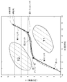
図5は、リンク姿勢算出処理のシミュレーション結果の一例を示す。ここでX軸は体の横方向を示し、ポート7の位置を基準値0としたとき、負のX値はポート7よりも左位置を、正のX値はポート7よりも右位置を表現する。Y軸は体内深部方向を示し、ポート7の位置を基準値0としたとき、負のY値は体外位置を、正のY値は体内の深さ位置を表現する。なお実際の体内空間は3次元であるが、ここでは2次元空間でのシミュレーションを行っている。
FIG. 5 shows an example of the simulation result of the link posture calculation process. Here, the X-axis indicates the lateral direction of the body, and when the position of the
図5において、白丸は、記憶部42に記憶された遠位端12の指定位置を示す。図5には、手術用器具5の第1リンク10a、第2リンク10b、第3リンク10cがポート7から体腔内に挿入されている様子が模式的に示されている。
In FIG. 5, the white circle indicates the designated position of the
制御部40は、移動軌跡と手術用器具5の位置との誤差が最小となるように、各リンク10の姿勢を算出する。従来から誤差を最小化するためのアルゴリズムは様々提案されているが、制御部40は任意の誤差最小化アルゴリズムを採用してよく、採用したアルゴリズムにより移動軌跡と手術用器具5の位置との誤差が最小となる各リンク10の姿勢を算出してよい。
The
具体的に制御部40は、第1リンク10aの先端位置(遠位端12の指定位置)とポート7の位置とを拘束条件として取り扱い、したがって遠位端12の指定位置とポート7の位置とは、誤差が0となるようにする。この拘束条件のもとで、制御部40は、過去の指定位置を滑らかに繋いだ移動軌跡と、各リンクの位置との誤差が最小となるように、最適化問題を計算する。
Specifically, the
たとえば制御部40は、過去の指定位置から各リンク10に対して垂線を下ろし、それぞれの垂線の二乗を求めて、その二乗の総和が最小となるように、各リンク10の姿勢を定めてよい。このとき制御部40は、最急降下法を用いて、誤差最小値を探索してよい。なお、過去の指定位置が所定時間ごとに算出されていると、指定位置の間隔は、時間帯によって異なることになる。そこで制御部40は、各リンク10における重みを調整するために、垂線長の二乗に対して、各リンク10ごとの重み係数を乗算することが好ましい。
For example, the
なお制御部40は、各リンク10を所定長に分割し、各リンク10の各分割点を通ってリンク10に垂直な平面と移動軌跡との交点を求め、交点と分割点の長さ(垂線長)を二乗して、最小二乗法により、各リンク10の姿勢を算出してよい。垂線を所定長ごとに引くことで、各リンク10の重みを均等にできる。各リンク10の姿勢は、連結するジョイント部11の制御パラメータとして利用され、制御部40は、各リンク10間が算出した姿勢となるように、各ジョイント部11を駆動する。なお制御部40は、遠位端12が指定位置に移動するまでの間を所定時間ごとに分割し、その分割した時間ごとに、各リンク10の姿勢を算出して、各ジョイント部11を駆動してよい。このようにして制御部40は、手術用器具5を、低侵襲経路に沿って体腔内で移動させることが可能となる。
The
制御部40は、体腔内に位置する全てのリンク10の位置と移動軌跡との誤差が最小となるように各リンク10の姿勢を算出することが好ましいが、体腔内に位置する一部のリンク10の位置と移動軌跡との誤差が最小となるように各リンク10の姿勢を算出してもよい。前者の場合、制御部40は、体腔内に位置する全てのリンク10の姿勢を同時に算出することで、目的とする誤差最小化を実現する。
It is preferable that the
一方で後者の場合、たとえば制御部40は、誤差最小化アルゴリズムをリンク10ごとに遠位端12側のリンク10から順番に適用して、各リンク10の姿勢を算出してよい。このとき制御部40は、各リンク10ごとに誤差最小となる姿勢を順番に算出することで、前者の場合と比べると計算量を大幅に低減できるが、ポート7を通る最後のリンク10の姿勢は、その一つ手前のリンク10の姿勢に依存して自動的に定まる。つまりポート7を通る最後のリンク10の姿勢の算出には、誤差最小化アルゴリズムが適用されない。しかしながら、この場合であっても遠位端12側のリンク10から最後のリンク10の一つ手前のリンク10までの姿勢は、誤差最小化アルゴリズムによって算出され、制御部40は、体腔内に挿入されている少なくとも一部のリンク10の姿勢を誤差最小化アルゴリズムにより算出することで、低侵襲な移動モードを実現できる。
On the other hand, in the latter case, for example, the
なお制御部40は、手術用器具5を体腔内で後退させるとき、すなわち手術用器具5を体腔内から引き抜く方向に動かすときも、同様に、低侵襲経路に沿って後退させてよい。制御部40は、記憶部42に記憶された過去の指定位置を用いて各ジョイント部11の姿勢を算出するが、後退時には、遠位端12よりも深部側に存在する過去の指定位置については演算負荷を低減するために、計算対象から除外してよい。
The
以上、本開示を実施例をもとに説明した。この実施例は例示であり、それらの各構成要素や各処理プロセスの組合せにいろいろな変形例が可能なこと、またそうした変形例も本開示の範囲にあることは当業者に理解されるところである。 The present disclosure has been described above based on the examples. It will be appreciated by those skilled in the art that this embodiment is exemplary and that various variations of each of these components and combinations of processing processes are possible and that such modifications are also within the scope of the present disclosure. ..
実施形態では、ユーザが遠隔操作装置2において操作部材を操作することで、位置指定操作を入力することを説明した。変形例では、遠隔操作装置2に設けた撮像装置がユーザの動きを撮影し、ユーザの動きが画像解析されることで、位置指定操作を入力できるようにしてもよい。また実施形態では、体腔内をカメラプローブ6により撮影することを説明したが、体腔内を撮影するカメラは手術用器具5に組み込まれていてもよい。
In the embodiment, it has been described that the user inputs the position designation operation by operating the operation member in the
本開示の態様の概要は、次の通りである。本開示のある態様は、ポートから体腔内に挿入されている手術用器具の動きを制御する制御装置である。手術用器具は、エンドエフェクタを保持する第1リンクと、第2リンクと、第1リンクと第2リンクを相対回転可能に連結する第1ジョイント部とを少なくとも有して構成される。制御装置は、ユーザから、第1リンクまたはエンドエフェクタの所定部分の体腔内における移動位置の指定操作を受け付ける受付部と、所定部分が、位置指定操作に応じた指定位置に移動するように、手術用器具の動きを制御する制御部と、を備える。制御部は、所定部分が指定位置に移動するまでの間に、第1リンクおよび第2リンクの姿勢を、体腔内における所定部分の移動軌跡にもとづいて算出する。 The outline of the aspects of the present disclosure is as follows. One aspect of the present disclosure is a control device that controls the movement of a surgical instrument inserted into a body cavity from a port. The surgical instrument is configured to have at least a first link for holding the end effector, a second link, and a first joint portion that rotatably connects the first link and the second link. The control device is operated so that the reception unit that receives the operation of designating the movement position in the body cavity of the predetermined part of the first link or the end effector from the user and the predetermined part move to the designated position according to the position designation operation. It is equipped with a control unit that controls the movement of equipment. The control unit calculates the postures of the first link and the second link based on the movement locus of the predetermined portion in the body cavity until the predetermined portion moves to the designated position.
この態様によると、手術用器具における第1リンクおよび第2リンクの姿勢を、既に体腔内を移動した所定部分の移動軌跡にもとづいて算出するため、手術用器具を低侵襲で移動させることが可能となる。 According to this aspect, since the postures of the first link and the second link in the surgical instrument are calculated based on the movement trajectory of the predetermined portion that has already moved in the body cavity, the surgical instrument can be moved with minimal invasiveness. It becomes.
制御部は、所定部分よりもポート側に位置するリンク部分が所定部分の移動軌跡に沿って移動するように、第1リンクおよび第2リンクの姿勢を算出してよい。制御部は、所定部分の移動軌跡と、手術用器具の位置との誤差が最小となるように、第1リンクおよび第2リンクの姿勢を算出してよい。 The control unit may calculate the postures of the first link and the second link so that the link portion located on the port side of the predetermined portion moves along the movement locus of the predetermined portion. The control unit may calculate the postures of the first link and the second link so that the error between the movement locus of the predetermined portion and the position of the surgical instrument is minimized.
本開示の別の態様は、ポートから体腔内に挿入されている手術用器具の動きを制御する方法である。手術用器具は、エンドエフェクタを保持する第1リンクと、第2リンクと、第1リンクと第2リンクを相対回転可能に連結する第1ジョイント部とを少なくとも有して構成される。この手術用器具制御方法は、ユーザから、第1リンクまたはエンドエフェクタの所定部分の体腔内における移動位置の指定操作を受け付けるステップと、所定部分が、位置指定操作に応じた指定位置に移動するように、手術用器具の動きを制御するステップと、を備える。手術用器具の動きを制御するステップは、所定部分が指定位置に移動するまでの間に、第1リンクおよび第2リンクの姿勢を、体腔内における所定部分の移動軌跡にもとづいて算出する。 Another aspect of the present disclosure is a method of controlling the movement of a surgical instrument inserted into a body cavity from a port. The surgical instrument is configured to have at least a first link for holding the end effector, a second link, and a first joint portion that rotatably connects the first link and the second link. This surgical instrument control method includes a step of accepting an operation of designating a movement position in a body cavity of a predetermined part of the first link or an end effector from a user, and the predetermined part is moved to a designated position according to the position designation operation. Also provided with a step to control the movement of the surgical instrument. The step of controlling the movement of the surgical instrument calculates the postures of the first link and the second link based on the movement trajectory of the predetermined portion in the body cavity until the predetermined portion moves to the designated position.
1・・・手術支援ロボットシステム、2・・・遠隔操作装置、3・・・手術ロボット装置、4・・・ロボットアーム、5,5a,5b・・・手術用器具、6・・・カメラプローブ、7・・・ポート、10a・・・第1リンク、10b・・・第2リンク、10c・・・第3リンク、10d・・・第4リンク、11a・・・第1ジョイント部、11b・・・第2ジョイント部、11c・・・第3ジョイント部、12・・・遠位端、13・・・エンドエフェクタ、30・・・制御装置、40・・・制御部、42・・・記憶部、44・・・受付部、46・・・画像送信部。 1 ... Surgical support robot system, 2 ... Remote control device, 3 ... Surgical robot device, 4 ... Robot arm, 5,5a, 5b ... Surgical instrument, 6 ... Camera probe , 7 ... Port, 10a ... 1st link, 10b ... 2nd link, 10c ... 3rd link, 10d ... 4th link, 11a ... 1st joint part, 11b ... 2nd joint part, 11c ... 3rd joint part, 12 ... distal end, 13 ... end effector, 30 ... control device, 40 ... control unit, 42 ... memory Department, 44 ... Reception department, 46 ... Image transmission department.
Claims (7)
ユーザから、第1リンクまたはエンドエフェクタの所定部分の体腔内における移動位置の指定操作を受け付ける受付部と、
所定部分が、位置指定操作に応じた指定位置に移動するように、手術用器具の動きを制御する制御部と、を備え、
前記制御部は、所定部分が指定位置に移動するまでの間に、所定部分よりもポート側に位置するリンク部分が体腔内における所定部分の移動軌跡に沿って移動するように、第1リンクおよび第2リンクの姿勢を算出する、
ことを特徴とする手術用器具制御装置。 A control device that controls the movement of a surgical instrument inserted into a body cavity from a port, wherein the surgical instrument has a first link, a second link, a first link, and a second link that hold an end effector. It is configured to have at least a first joint that connects the links so that they can rotate relative to each other.
A reception unit that accepts from the user an operation to specify the movement position in the body cavity of the predetermined part of the first link or the end effector.
It is equipped with a control unit that controls the movement of the surgical instrument so that the predetermined portion moves to the designated position according to the position designation operation.
In the control unit, the first link and the link portion located on the port side of the predetermined portion move along the movement trajectory of the predetermined portion in the body cavity until the predetermined portion moves to the designated position. Calculate the attitude of the second link,
A surgical instrument control device characterized by this.
ユーザから、第1リンクまたはエンドエフェクタの所定部分の体腔内における移動位置の指定操作を受け付ける受付部と、
位置指定操作から指定位置を算出して、所定部分が、当該指定位置に移動するように、手術用器具の動きを制御する制御部と、
前記制御部が算出した指定位置を記憶する記憶部と、を備え、
前記制御部は、所定部分が指定位置に移動するまでの間に、第1リンクおよび第2リンクの姿勢を、前記記憶部に記憶された複数の過去の指定位置を繋いだ移動軌跡にもとづいて算出する、
ことを特徴とする手術用器具制御装置。 A control device that controls the movement of a surgical instrument inserted into a body cavity from a port, wherein the surgical instrument has a first link, a second link, a first link, and a second link that hold an end effector. It is configured to have at least a first joint that connects the links so that they can rotate relative to each other.
A reception unit that accepts from the user an operation to specify the movement position in the body cavity of the predetermined part of the first link or the end effector.
A control unit that calculates the designated position from the position designation operation and controls the movement of the surgical instrument so that the predetermined part moves to the designated position.
A storage unit that stores a designated position calculated by the control unit is provided.
The control unit determines the postures of the first link and the second link based on the movement locus connecting a plurality of past designated positions stored in the storage unit until the predetermined portion moves to the designated position. calculate,
A surgical instrument control device characterized by this.
ことを特徴とする請求項1または2に記載の手術用器具制御装置。 The control unit calculates the postures of the first link and the second link so that the error between the movement locus of the predetermined portion and the position of the surgical instrument is minimized.
The surgical instrument control device according to claim 1 or 2.
前記制御装置が、
ユーザから、第1リンクまたはエンドエフェクタの所定部分の体腔内における移動位置の指定操作を受け付けるステップと、
位置指定操作から、所定部分の移動先となる指定位置を算出するステップと、
所定部分よりもポート側に位置するリンク部分が体腔内における所定部分の移動軌跡に沿って移動するように、第1リンクおよび第2リンクの姿勢を算出するステップと、
を実施することを特徴とする手術用器具制御方法。 A control device is a method of calculating the posture of a surgical instrument inserted into a body cavity from a port, wherein the surgical instrument has a first link, a second link, and a first link for holding an end effector. It is configured to have at least a first joint portion that connects the second link and the second link so as to be relatively rotatable.
The control device
A step of accepting an operation of designating a movement position in a predetermined part of the first link or the end effector from the user, and
From the position specification operation, the step to calculate the specified position to move the predetermined part, and
A step of calculating the postures of the first link and the second link so that the link portion located on the port side of the predetermined portion moves along the movement trajectory of the predetermined portion in the body cavity .
A surgical instrument control method characterized by performing .
前記制御装置が、
ユーザから、第1リンクまたはエンドエフェクタの所定部分の体腔内における移動位置の指定操作を受け付けるステップと、
位置指定操作から、所定部分の移動先となる指定位置を算出するステップと、
算出した指定位置を記憶部に記憶するステップと、
第1リンクおよび第2リンクの姿勢を、前記記憶部に記憶された複数の過去の指定位置を繋いだ移動軌跡にもとづいて算出するステップと、
を実施することを特徴とする手術用器具制御方法。 A control device is a method of calculating the posture of a surgical instrument inserted into a body cavity from a port, wherein the surgical instrument has a first link, a second link, and a first link for holding an end effector. It is configured to have at least a first joint portion that connects the second link and the second link so as to be relatively rotatable.
The control device
A step of accepting an operation of designating a movement position in a predetermined part of the first link or the end effector from the user, and
From the position specification operation, the step to calculate the specified position to move the predetermined part, and
A step to store the calculated specified position in the storage unit,
A step of calculating the postures of the first link and the second link based on a movement locus connecting a plurality of past designated positions stored in the storage unit, and
A surgical instrument control method characterized by performing .
ユーザから、手術用器具の所定部分の体腔内における移動位置の指定操作を受け付ける機能と、
所定部分が、位置指定操作に応じた指定位置に移動するように、手術用器具の動きを制御する機能と、を実現させるためのプログラムであって、
当該手術用器具は、エンドエフェクタを保持する第1リンクと、第2リンクと、第1リンクと第2リンクを相対回転可能に連結する第1ジョイント部とを少なくとも有して構成されており、
手術用器具の動きを制御する機能は、所定部分が指定位置に移動するまでの間に、所定部分よりもポート側に位置するリンク部分が体腔内における所定部分の移動軌跡に沿って移動するように、第1リンクおよび第2リンクの姿勢を算出する機能を含む、
ことを特徴とするプログラム。 A computer that controls the movement of surgical instruments inserted into the body cavity from the port,
A function that accepts from the user an operation to specify the movement position in the body cavity of a predetermined part of the surgical instrument,
It is a program for realizing a function of controlling the movement of a surgical instrument so that a predetermined part moves to a designated position according to a position designation operation.
The surgical instrument is configured to have at least a first link for holding an end effector, a second link, and a first joint portion that rotatably connects the first link and the second link.
The function to control the movement of the surgical instrument is that the link part located on the port side of the predetermined part moves along the movement trajectory of the predetermined part in the body cavity until the predetermined part moves to the specified position. Including the function of calculating the posture of the first link and the second link,
A program characterized by that.
ユーザから、手術用器具の所定部分の体腔内における移動位置の指定操作を受け付ける機能と、
位置指定操作から指定位置を算出する機能と、
所定部分が、算出した指定位置に移動するように、手術用器具の動きを制御する機能と、
算出した指定位置を記憶部に記憶する機能と、を実現させるためのプログラムであって、
当該手術用器具は、エンドエフェクタを保持する第1リンクと、第2リンクと、第1リンクと第2リンクを相対回転可能に連結する第1ジョイント部とを少なくとも有して構成されており、
手術用器具の動きを制御する機能は、所定部分が指定位置に移動するまでの間に、第1リンクおよび第2リンクの姿勢を、前記記憶部に記憶された複数の過去の指定位置を繋いだ移動軌跡にもとづいて算出する機能を含む、
ことを特徴とするプログラム。 A computer that controls the movement of surgical instruments inserted into the body cavity from the port,
A function that accepts from the user an operation to specify the movement position in the body cavity of a predetermined part of the surgical instrument,
A function to calculate the specified position from the position specification operation and
A function to control the movement of the surgical instrument so that the predetermined part moves to the calculated specified position,
It is a program to realize the function of storing the calculated specified position in the storage unit .
The surgical instrument is configured to have at least a first link for holding an end effector, a second link, and a first joint portion that rotatably connects the first link and the second link.
The function of controlling the movement of the surgical instrument connects the postures of the first link and the second link to a plurality of past designated positions stored in the storage unit until the predetermined portion moves to the designated position. Including the function to calculate based on the movement trajectory,
A program characterized by that.
Priority Applications (2)
| Application Number | Priority Date | Filing Date | Title |
|---|---|---|---|
| JP2018008700A JP7064190B2 (en) | 2018-01-23 | 2018-01-23 | Surgical instrument control device and surgical instrument control method |
| PCT/JP2019/000553 WO2019146417A1 (en) | 2018-01-23 | 2019-01-10 | Device for controlling surgical instrument, and method for controlling surgical instrument |
Applications Claiming Priority (1)
| Application Number | Priority Date | Filing Date | Title |
|---|---|---|---|
| JP2018008700A JP7064190B2 (en) | 2018-01-23 | 2018-01-23 | Surgical instrument control device and surgical instrument control method |
Publications (2)
| Publication Number | Publication Date |
|---|---|
| JP2019126450A JP2019126450A (en) | 2019-08-01 |
| JP7064190B2 true JP7064190B2 (en) | 2022-05-10 |
Family
ID=67394954
Family Applications (1)
| Application Number | Title | Priority Date | Filing Date |
|---|---|---|---|
| JP2018008700A Active JP7064190B2 (en) | 2018-01-23 | 2018-01-23 | Surgical instrument control device and surgical instrument control method |
Country Status (2)
| Country | Link |
|---|---|
| JP (1) | JP7064190B2 (en) |
| WO (1) | WO2019146417A1 (en) |
Families Citing this family (2)
| Publication number | Priority date | Publication date | Assignee | Title |
|---|---|---|---|---|
| CN110464469B (en) * | 2019-09-10 | 2020-12-01 | 深圳市精锋医疗科技有限公司 | Surgical robot, method and device for controlling distal end instrument, and storage medium |
| CN116400671B (en) * | 2023-04-27 | 2024-04-05 | 广州鼎盛医疗技术服务有限公司 | Master-slave control time delay test method, system and medium of remote ultrasonic diagnosis and treatment equipment |
Citations (5)
| Publication number | Priority date | Publication date | Assignee | Title |
|---|---|---|---|---|
| JP2004129782A (en) | 2002-10-09 | 2004-04-30 | Hitachi Ltd | Surgical manipulator and its operation input apparatus |
| JP2009107074A (en) | 2007-10-30 | 2009-05-21 | Olympus Medical Systems Corp | Manipulator apparatus and medical device system |
| JP2009539573A5 (en) | 2007-06-13 | 2010-08-05 | ||
| US20110319714A1 (en) | 2010-06-24 | 2011-12-29 | Hansen Medical, Inc. | Methods and devices for controlling a shapeable medical device |
| US20140058406A1 (en) | 2012-08-24 | 2014-02-27 | Nikolaos V. Tsekos | Robotic Device and Systems for Image-Guided and Robot-Assisted Surgery |
Family Cites Families (2)
| Publication number | Priority date | Publication date | Assignee | Title |
|---|---|---|---|---|
| FR2884965B1 (en) * | 2005-04-26 | 2007-06-08 | Commissariat Energie Atomique | ADJUSTABLE MASK WHITE STRUCTURE FOR EUV MASK WITH PHASE SHIFT |
| US20080065101A1 (en) * | 2006-06-13 | 2008-03-13 | Intuitive Surgical, Inc. | Minimally invasive surgical apparatus with side exit instruments |
-
2018
- 2018-01-23 JP JP2018008700A patent/JP7064190B2/en active Active
-
2019
- 2019-01-10 WO PCT/JP2019/000553 patent/WO2019146417A1/en active Application Filing
Patent Citations (5)
| Publication number | Priority date | Publication date | Assignee | Title |
|---|---|---|---|---|
| JP2004129782A (en) | 2002-10-09 | 2004-04-30 | Hitachi Ltd | Surgical manipulator and its operation input apparatus |
| JP2009539573A5 (en) | 2007-06-13 | 2010-08-05 | ||
| JP2009107074A (en) | 2007-10-30 | 2009-05-21 | Olympus Medical Systems Corp | Manipulator apparatus and medical device system |
| US20110319714A1 (en) | 2010-06-24 | 2011-12-29 | Hansen Medical, Inc. | Methods and devices for controlling a shapeable medical device |
| US20140058406A1 (en) | 2012-08-24 | 2014-02-27 | Nikolaos V. Tsekos | Robotic Device and Systems for Image-Guided and Robot-Assisted Surgery |
Also Published As
| Publication number | Publication date |
|---|---|
| WO2019146417A1 (en) | 2019-08-01 |
| JP2019126450A (en) | 2019-08-01 |
Similar Documents
| Publication | Publication Date | Title |
|---|---|---|
| JP7434246B2 (en) | System and method for positioning a manipulator arm by clutching in zero orthogonal space simultaneously with zero space movement | |
| JP7022709B2 (en) | Computer-aided medical system and method | |
| CN108143497B (en) | System and method for tracking a path using null space | |
| JP6535653B2 (en) | System and method for facilitating access to the edge of Cartesian coordinate space using zero space | |
| KR102229337B1 (en) | Systems and methods for proximal control of a surgical instrument | |
| CN107595392B (en) | Avoidance of manipulator arm collisions with patient using null space | |
| JP2019111352A (en) | Systems and methods for using null space to emphasize manipulator joint motion anisotropically | |
| US20140343569A1 (en) | Grip force normalization for surgical instrument | |
| JP2015535693A (en) | Phantom freedom for manipulating machine body movement | |
| JP2015502768A (en) | Robotic operating table | |
| JP2023549687A (en) | Laparoscopic surgical robot system with internal joint degrees of freedom | |
| JP2022543572A (en) | Robot arm with extendable prism link | |
| US11832911B2 (en) | Surgical platform supported by multiple arms | |
| KR20230002996A (en) | Remote kinematic center control for surgical robots | |
| JP7064190B2 (en) | Surgical instrument control device and surgical instrument control method | |
| US11918312B2 (en) | Regulating joint space velocity of a surgical robotic arm | |
| EP4125686A1 (en) | Systems and methods for constrained motion control of medical instruments | |
| Boyraz et al. | Robotic surgery | |
| Ahmad et al. | Design and shared control of a flexible endoscope with autonomous distal tip alignment | |
| CN115363772A (en) | Surgical robot adjusting method, readable storage medium and surgical robot system |
Legal Events
| Date | Code | Title | Description |
|---|---|---|---|
| A621 | Written request for application examination |
Free format text: JAPANESE INTERMEDIATE CODE: A621 Effective date: 20210119 |
|
| A131 | Notification of reasons for refusal |
Free format text: JAPANESE INTERMEDIATE CODE: A131 Effective date: 20210831 |
|
| A521 | Request for written amendment filed |
Free format text: JAPANESE INTERMEDIATE CODE: A523 Effective date: 20211022 |
|
| A521 | Request for written amendment filed |
Free format text: JAPANESE INTERMEDIATE CODE: A523 Effective date: 20211025 |
|
| A521 | Request for written amendment filed |
Free format text: JAPANESE INTERMEDIATE CODE: A523 Effective date: 20211104 |
|
| TRDD | Decision of grant or rejection written | ||
| A01 | Written decision to grant a patent or to grant a registration (utility model) |
Free format text: JAPANESE INTERMEDIATE CODE: A01 Effective date: 20220315 |
|
| A61 | First payment of annual fees (during grant procedure) |
Free format text: JAPANESE INTERMEDIATE CODE: A61 Effective date: 20220408 |
|
| R150 | Certificate of patent or registration of utility model |
Ref document number: 7064190 Country of ref document: JP Free format text: JAPANESE INTERMEDIATE CODE: R150 |