JP7063560B2 - Methods and equipment for adaptive robotic end effectors - Google Patents
Methods and equipment for adaptive robotic end effectors Download PDFInfo
- Publication number
- JP7063560B2 JP7063560B2 JP2017169203A JP2017169203A JP7063560B2 JP 7063560 B2 JP7063560 B2 JP 7063560B2 JP 2017169203 A JP2017169203 A JP 2017169203A JP 2017169203 A JP2017169203 A JP 2017169203A JP 7063560 B2 JP7063560 B2 JP 7063560B2
- Authority
- JP
- Japan
- Prior art keywords
- end effector
- workpiece
- feature
- contact
- adaptive
- Prior art date
- Legal status (The legal status is an assumption and is not a legal conclusion. Google has not performed a legal analysis and makes no representation as to the accuracy of the status listed.)
- Active
Links
Images


Classifications
-
- B—PERFORMING OPERATIONS; TRANSPORTING
- B25—HAND TOOLS; PORTABLE POWER-DRIVEN TOOLS; MANIPULATORS
- B25J—MANIPULATORS; CHAMBERS PROVIDED WITH MANIPULATION DEVICES
- B25J9/00—Programme-controlled manipulators
- B25J9/16—Programme controls
- B25J9/1679—Programme controls characterised by the tasks executed
- B25J9/1692—Calibration of manipulator
-
- B—PERFORMING OPERATIONS; TRANSPORTING
- B25—HAND TOOLS; PORTABLE POWER-DRIVEN TOOLS; MANIPULATORS
- B25J—MANIPULATORS; CHAMBERS PROVIDED WITH MANIPULATION DEVICES
- B25J15/00—Gripping heads and other end effectors
-
- B—PERFORMING OPERATIONS; TRANSPORTING
- B25—HAND TOOLS; PORTABLE POWER-DRIVEN TOOLS; MANIPULATORS
- B25J—MANIPULATORS; CHAMBERS PROVIDED WITH MANIPULATION DEVICES
- B25J17/00—Joints
- B25J17/02—Wrist joints
- B25J17/0208—Compliance devices
-
- B—PERFORMING OPERATIONS; TRANSPORTING
- B25—HAND TOOLS; PORTABLE POWER-DRIVEN TOOLS; MANIPULATORS
- B25J—MANIPULATORS; CHAMBERS PROVIDED WITH MANIPULATION DEVICES
- B25J13/00—Controls for manipulators
- B25J13/08—Controls for manipulators by means of sensing devices, e.g. viewing or touching devices
- B25J13/081—Touching devices, e.g. pressure-sensitive
-
- B—PERFORMING OPERATIONS; TRANSPORTING
- B25—HAND TOOLS; PORTABLE POWER-DRIVEN TOOLS; MANIPULATORS
- B25J—MANIPULATORS; CHAMBERS PROVIDED WITH MANIPULATION DEVICES
- B25J17/00—Joints
- B25J17/02—Wrist joints
- B25J17/0208—Compliance devices
- B25J17/0233—Compliance devices with radial compliance, i.e. perpendicular to the longitudinal wrist axis
-
- B—PERFORMING OPERATIONS; TRANSPORTING
- B25—HAND TOOLS; PORTABLE POWER-DRIVEN TOOLS; MANIPULATORS
- B25J—MANIPULATORS; CHAMBERS PROVIDED WITH MANIPULATION DEVICES
- B25J17/00—Joints
- B25J17/02—Wrist joints
- B25J17/0258—Two-dimensional joints
- B25J17/0275—Universal joints, e.g. Hooke, Cardan, ball joints
-
- B—PERFORMING OPERATIONS; TRANSPORTING
- B25—HAND TOOLS; PORTABLE POWER-DRIVEN TOOLS; MANIPULATORS
- B25J—MANIPULATORS; CHAMBERS PROVIDED WITH MANIPULATION DEVICES
- B25J9/00—Programme-controlled manipulators
- B25J9/16—Programme controls
- B25J9/1628—Programme controls characterised by the control loop
- B25J9/1633—Programme controls characterised by the control loop compliant, force, torque control, e.g. combined with position control
-
- B—PERFORMING OPERATIONS; TRANSPORTING
- B25—HAND TOOLS; PORTABLE POWER-DRIVEN TOOLS; MANIPULATORS
- B25J—MANIPULATORS; CHAMBERS PROVIDED WITH MANIPULATION DEVICES
- B25J9/00—Programme-controlled manipulators
- B25J9/16—Programme controls
- B25J9/1656—Programme controls characterised by programming, planning systems for manipulators
- B25J9/1669—Programme controls characterised by programming, planning systems for manipulators characterised by special application, e.g. multi-arm co-operation, assembly, grasping
-
- G—PHYSICS
- G01—MEASURING; TESTING
- G01B—MEASURING LENGTH, THICKNESS OR SIMILAR LINEAR DIMENSIONS; MEASURING ANGLES; MEASURING AREAS; MEASURING IRREGULARITIES OF SURFACES OR CONTOURS
- G01B3/00—Measuring instruments characterised by the use of mechanical techniques
- G01B3/20—Slide gauges
-
- G—PHYSICS
- G01—MEASURING; TESTING
- G01B—MEASURING LENGTH, THICKNESS OR SIMILAR LINEAR DIMENSIONS; MEASURING ANGLES; MEASURING AREAS; MEASURING IRREGULARITIES OF SURFACES OR CONTOURS
- G01B3/00—Measuring instruments characterised by the use of mechanical techniques
- G01B3/22—Feeler-pin gauges, e.g. dial gauges
- G01B3/28—Depth gauges
-
- G—PHYSICS
- G01—MEASURING; TESTING
- G01B—MEASURING LENGTH, THICKNESS OR SIMILAR LINEAR DIMENSIONS; MEASURING ANGLES; MEASURING AREAS; MEASURING IRREGULARITIES OF SURFACES OR CONTOURS
- G01B5/00—Measuring arrangements characterised by the use of mechanical techniques
- G01B5/02—Measuring arrangements characterised by the use of mechanical techniques for measuring length, width or thickness
- G01B5/06—Measuring arrangements characterised by the use of mechanical techniques for measuring length, width or thickness for measuring thickness
Description
本開示は概してロボット式の製造動作に関し、詳細には、製造への応用のためにロボットアームに取り付けられるエンドエフェクタの位置付けに関する。より詳細には、本開示は、ターゲット位置が変動する被加工物にロボット式エンドエフェクタを正確に位置付けるための方法及び装置に関する。 The present disclosure relates generally to robotic manufacturing operations and, in particular, to the positioning of end effectors attached to robotic arms for manufacturing applications. More specifically, the present disclosure relates to methods and devices for accurately positioning a robotic end effector on a workpiece whose target position fluctuates.
ロボットアームデバイスの制御を伴う、製造への応用においては、任意の動作が実施される被加工物に対して、ロボットマニピュレータ又はロボットエンドエフェクタを精密に位置付けることが必要になる。ロボットアームデバイスを使用する多くの応用では、ロボットの位置付け及び配向の制御に対する決定論的アプローチが前提とされる。この決定論的アプローチはロボットの作業セル条件が一定であることを予期するものであり、ロボットの運動制御により、全ての新規被加工物に常に同じ結果が発生することになる。 In manufacturing applications involving the control of robot arm devices, it is necessary to precisely position the robot manipulator or robot end effector with respect to the workpiece on which any movement is to be performed. Many applications using robotic arm devices presuppose a deterministic approach to controlling the positioning and orientation of the robot. This deterministic approach expects the robot's working cell conditions to be constant, and the robot's motion control will always produce the same result for all new workpieces.
しかし、一部の応用、特に大型部品を伴う応用に関しては、一定の作業セル及び被加工物条件についての決定論的な前提は、通常有効ではない。例えば、被加工物の熱膨張及び/又は収縮といった変化する環境的条件は、多くの場合、被加工物におけるターゲット位置の変動をもたらす。被加工物におけるターゲット位置が変動しうる、このようなロボット応用形態に関しては、エンドエフェクタと被加工物フィーチャとの正確な位置合わせを実現することが困難である。 However, for some applications, especially those involving large parts, deterministic assumptions about certain working cell and workpiece conditions are usually not valid. For example, changing environmental conditions such as thermal expansion and / or contraction of the workpiece often result in variations in the target position in the workpiece. For such robot applications where the target position on the workpiece can fluctuate, it is difficult to achieve accurate alignment of the end effector with the workpiece feature.
ある動作により、被加工物のフィーチャとエンドエフェクタを精密に位置合わせする(例えば、測定のようなタスクのために穴の中にツールを挿入する)ことが必要な状況では、エンドエフェクタの不正確な配置が、エンドエフェクタ、被加工物、又はその両方に損傷を引き起こしうる。エンドエフェクタが不正確に配置されると、ロボットによって実行されるあらゆる自動タスクが停止せざるをえない。この問題に対処するために作業人員が介入することが、たびたび必要とされる。 End effector inaccuracies in situations where certain movements require precise alignment of the features of the workpiece with the end effector (eg, inserting a tool into the hole for a task such as measurement). The arrangement can cause damage to the end effector, the workpiece, or both. Improper placement of the end effector forces all automated tasks performed by the robot to stop. It is often necessary for workers to intervene to address this issue.
被加工物フィーチャの付近でのエンドエフェクタの正確な位置付けを伴う、標準的なロボット制御の応用では、位置ずれが起こると、オペレータがロボット制御プログラムを停止させて被加工物又はロボットの位置調整を実施し、次いで制御プログラム再始動させることが必要になる。人間の介入を伴うこの中断、調整、及び再始動というアプローチによりタスクを完遂することは、可能であるが、非常に非効率的である。 In standard robot control applications, which involve accurate positioning of the end effector near the workpiece feature, the operator stops the robot control program to reposition the workpiece or robot when misalignment occurs. It will be necessary to implement and then restart the control program. It is possible, but very inefficient, to complete the task with this interruption, coordination, and restart approach involving human intervention.
より順応性のある応用では、位置ずれ問題に対処するために視覚システムが使用されてきた。視覚システムは、典型的には、カメラが取り付けられているエンドエフェクタをフィーチャ位置に移動させることを伴う。カメラは対象のエリアの写真を撮る。制御システムは、画像内の正しいフィーチャを特定し、エンドエフェクタを正しい位置に移動させるために必要な局所的オフセットを算出する。ロボットは次いで、別のロボット移動を実行することによって、エンドエフェクタを正しい位置に移動させる。 In more adaptable applications, visual systems have been used to address misalignment problems. The visual system typically involves moving the end effector to which the camera is mounted to a feature location. The camera takes a picture of the area of interest. The control system identifies the correct features in the image and calculates the local offset required to move the end effector to the correct position. The robot then moves the end effector to the correct position by performing another robot movement.
視覚システムは、表面外観に変動のない被加工物に対して、及び、厳密に制御された照明条件のもとでは、良好に機能しうる。しかし、視覚システムは、高価であることも、既存のロボットシステムへの統合が困難なこともある。更に、視覚システムには、多くの場合、相当量の初期校正及び稼働中の校正、並びに特殊な整備が必要になる。 The visual system can work well for workpieces with no variation in surface appearance and under tightly controlled lighting conditions. However, visual systems can be expensive and difficult to integrate into existing robotic systems. In addition, visual systems often require a significant amount of initial calibration, in-service calibration, and special maintenance.
外部カメラシステムが、別種の既存手法である。外部カメラシステムは、ロボット自体ではなく環境の中に配置された、一又は複数の外部カメラ又は他のセンサを使用する。外部カメラシステムのような応用では、フィーチャに対するエンドエフェクタの相対的な位置及び配向が測定される。しかし、他の視覚システムと同様に、外部カメラシステムも、変動のない表面外観、及び厳密に制御された照明条件のもとにあることに、大きく依拠する。 The external camera system is another type of existing method. The external camera system uses one or more external cameras or other sensors located in the environment rather than the robot itself. In applications such as external camera systems, the relative position and orientation of the end effector with respect to the feature is measured. However, like other visual systems, external camera systems rely heavily on their stable surface appearance and tightly controlled lighting conditions.
光学的モーションキャプチャシステムは、上述の外部カメラシステムの一変形例である。光学的モーションキャプチャシステムは、エンドエフェクタ及び被加工物に配置された再帰反射マーカーを利用する。再帰反射マーカーが他のカメラシステムにある照明問題の一部を克服するので、光学的モーションキャプチャシステムは、他のものよりは、表面外観又は周囲の照明条件に依存しなくなる。しかし、他の種類の視覚ベースのシステムと同様に、光学的モーションキャプチャシステムも、初期校正及び特殊整備の問題を有しており、典型的には非常に高価である。 The optical motion capture system is a modification of the external camera system described above. Optical motion capture systems utilize retroreflective markers placed on end effectors and workpieces. Optical motion capture systems are less dependent on surface appearance or ambient lighting conditions than others, as retroreflective markers overcome some of the lighting problems found in other camera systems. However, like other types of visual-based systems, optical motion capture systems have initial calibration and special maintenance issues and are typically very expensive.
特殊な座標測定機器(CMM)は、多種多様な測定タスクに使用されるガントリのようなデバイスである。しかしCMMは、典型的には、作業量が限定されている大型で重いデバイスである。大型の又は複雑な被加工物に対する動作にCMMを使用するのは、困難で時間がかかることである。 A special coordinate measuring device (CMM) is a gantry-like device used for a wide variety of measurement tasks. However, CMMs are typically large, heavy devices with limited workload. The use of CMMs for operations on large or complex workpieces is difficult and time consuming.
したがって、上述の問題の少なくとも一部、並びに他の起こりうる問題を考慮している、方法及び装置を有することが望ましいと言える。 Therefore, it may be desirable to have methods and devices that take into account at least some of the above problems, as well as other possible problems.
一実施例では、装置は、ロボットデバイスに取り付けられる多軸適応型(multi-axis compliant)エンドエフェクタを備える。このエンドエフェクタは、適応型接触プローブを備える。適応型接触プローブは、被加工物フィーチャの実際の位置を接触によって判定するよう構成される。エンドエフェクタは、それに加えて、適応型接触プローブに関連する、少なくとも1つの並進式接合部と、少なくとも1つの回転式接合部とを備える。少なくとも1つの並進式接合部及び少なくとも1つの回転式接合部は、被加工物フィーチャと適応型接触プローブを受動的に位置合わせするよう、構成される。 In one embodiment, the device comprises a multi-axis compact end effector that is attached to a robotic device. This end effector comprises an adaptive contact probe. The adaptive contact probe is configured to determine the actual position of the workpiece feature by contact. The end effector additionally comprises at least one translational junction and at least one rotary junction associated with the adaptive contact probe. At least one translational junction and at least one rotary junction are configured to passively align the workpiece feature with the adaptive contact probe.
別の実施例では、ロボットデバイスに取り付けられる多軸適応型エンドエフェクタを使用して被加工物に自動的に動作を実施するための、方法が提供される。この方法は、動作が実施される被加工物フィーチャの公称位置(nominal location)に、エンドエフェクタを位置付けることを含む。方法は、それに加えて、被加工物フィーチャとエンドエフェクタを受動的に位置合わせするために、エンドエフェクタを被加工物フィーチャに接触させることを含む。方法は、それに加えて、被加工物フィーチャとエンドエフェクタを位置合わせすることに応じて、被加工物フィーチャに動作を実施することを含む。 Another embodiment provides a method for automatically performing motion on a workpiece using a multi-axis adaptive end effector attached to a robotic device. This method involves positioning the end effector at the nominal location of the workpiece feature on which the operation is performed. The method additionally comprises bringing the end effector into contact with the workpiece feature in order to passively align the workpiece feature with the end effector. The method additionally comprises performing an action on the workpiece feature in response to aligning the workpiece feature with the end effector.
また別の実施例では、ロボットデバイスに取り付けられる多軸適応型エンドエフェクタを使用して被加工物に自動的に動作を実施するための、コンピュータプログラム製品が提供される。このコンピュータプログラム製品は、コンピュータ可読記憶媒体を備える。コンピュータプログラム製品は、動作が実施される被加工物フィーチャの公称位置にエンドエフェクタを位置付けるための、コンピュータ可読記憶媒体に記憶された第1プログラムコードを含む。コンピュータプログラム製品は、それに加えて、エンドエフェクタを被加工物フィーチャに接触させて、被加工物フィーチャとエンドエフェクタを受動的に位置合わせするための、コンピュータ可読記憶媒体に記憶された第2プログラムコードを含む。コンピュータプログラム製品は、それに加えて、被加工物フィーチャとエンドエフェクタを位置合わせすることに応じて、被加工物フィーチャに動作を実施するための、コンピュータ可読記憶媒体に記憶された第3プログラムコードを含む。 In yet another embodiment, a computer program product is provided for automatically performing an action on a workpiece using a multi-axis adaptive end effector attached to a robot device. This computer program product comprises a computer readable storage medium. The computer program product includes a first program code stored in a computer-readable storage medium for positioning the end effector at the nominal position of the workpiece feature on which the operation is performed. The computer program product additionally has a second program code stored in a computer-readable storage medium for contacting the work piece feature with the end effector to passively align the work piece feature with the end effector. including. The computer program product additionally provides a third program code stored in a computer-readable storage medium for performing actions on the workpiece feature in response to aligning the workpiece feature with the end effector. include.
これらの特徴及び機能は、本開示の様々な例において個別に実現可能であるか、又は、後述の説明及び図面を参照して更なる詳細が理解されうる、更に別の例において組み合わされうる。 These features and functions may be individually feasible in the various examples of the present disclosure, or may be combined in yet another example where further details can be understood with reference to the description and drawings below.
実施例の特性と考えられる新規な特徴は、付随する特許請求の範囲に明記される。しかし、実施例及び好ましい使用モードと、それらの更なる目的及び特徴は、添付図面と併せて後述の本開示の実施例の詳細説明を参照することにより、最もよく理解されよう。 The novel features that are considered to be the characteristics of the examples are specified in the accompanying claims. However, examples and preferred modes of use and their further objectives and features will be best understood by reference to the detailed description of the embodiments of the present disclosure described below in conjunction with the accompanying drawings.
実施例では、種々の検討事項が考慮される。例えば、実施例では、ロボットオペレータを伴う製造への応用の実施が望ましい可能性があることが、考慮されている。更に、実施例では、被加工物に対してロボットを精密に位置付けるための方法及び装置を有し、その被加工物に製造動作を実施することが望ましいかもしれないということも、考慮されている。詳細には、実施例では、製造済みの飛行機構成要素などの大型の被加工物に対してロボットを精密に位置付け、その被加工物の穴又は切り欠きの厚さを正確に測定するための、方法及び装置を有することが望ましいかもしれないということが、考慮されている。 In the examples, various considerations are considered. For example, in the embodiments, it is considered that implementation of manufacturing applications involving robot operators may be desirable. Further, it is also considered that in the embodiments, it may be desirable to have a method and device for precisely positioning the robot with respect to the workpiece and to carry out a manufacturing operation on the workpiece. .. Specifically, in the embodiments, the robot is precisely positioned with respect to a large workpiece, such as a manufactured airplane component, to accurately measure the thickness of a hole or notch in the workpiece. It is taken into account that it may be desirable to have methods and equipment.
ゆえに、実施例は、被加工物及び被加工物フィーチャの公称位置と被加工物及び被加工物フィーチャの実際の位置との間に不一致が存在する可能性がある状況において、エンドエフェクタと被加工物フィーチャとの位置合わせを可能にする、方法及び装置を提供する。この性能は、ロボットの再プログラミングを必要とせずにロボットの経路プログラムを再使用することを可能にするものであり、かつ、被加工物との位置合わせ接触が許容される状況に適用可能である。 Therefore, the examples are end effectors and workpieces in situations where there may be a discrepancy between the nominal position of the workpiece and the workpiece feature and the actual position of the workpiece and the workpiece feature. Provided are methods and devices that enable alignment with object features. This performance allows the robot's path program to be reused without the need for robot reprogramming, and is applicable in situations where aligned contact with the workpiece is allowed. ..
実施例は、ロボットアーム又はガントリに取り付けられる、適応型の自己位置合わせロボット式エンドエフェクタであって、システムが実際のフィーチャ位置の公称値からのずれを補償することを可能にする、ロボット式エンドエフェクタを提供する。このエンドエフェクタは、被加工物及び被加工物フィーチャとの適切な位置合わせを、たとえそのフィーチャの実際の位置が正確には分かっていない場合であっても可能にするために、回転式及び並進式の適応型要素を使用する。エンドエフェクタは、特に大型の対象物について、穴、スロット、及び他の種類の切り欠きに関連する表面厚さ測定を正確に実施する。 An embodiment is an adaptive self-aligning robotic end effector mounted on a robotic arm or gantry that allows the system to compensate for deviations from the nominal value of the actual feature position. Provide effectors. This end effector is rotary and translational to allow proper alignment of the workpiece and the workpiece feature, even if the actual position of the feature is not known exactly. Use the adaptive element of the expression. End effectors accurately perform surface thickness measurements related to holes, slots, and other types of notches, especially for large objects.
したがって、実施例のエンドエフェクタ及び制御プロセスは、フィーチャの公称位置向けに開発されたロボット制御プログラムが、小さい~中ぐらいの大きさの、被加工物及びフィーチャの位置の公称値からのずれを許容することを可能にする、位置合わせ補償方法を提供する。 Therefore, in the end effector and control process of the embodiment, the robot control program developed for the nominal position of the feature allows small to medium sized deviations from the nominal position of the workpiece and feature. Provides an alignment compensation method that makes it possible to do so.
実施例は、複数の一体型の並進式接合部、回転式接合部、及び磁気デテントを伴う適応設計を使用する、エンドエフェクタを提供し、この適応設計により、エンドエフェクタが、非理想的な条件に受動的に適合し、なおかつ、プログラムされた動作を実施することが可能になる。この適合可能性により、公称フィーチャ位置向けに開発されたロボット応用形態が、完了したプログラムを部分的にさかのぼって被加工物又はロボットの位置の調整を行うための、ロボット経路の再プログラミング、又は運動プログラムの停止を必要とせずに、極端ではない位置不一致を伴う状況において使用されることが可能になる。 The embodiment provides an end effector using an adaptive design with multiple integrated translational joints, rotary joints, and magnetic detents, which allows the end effector to be in non-ideal conditions. It is possible to passively adapt to and still perform programmed actions. This adaptability allows robot applications developed for nominal feature positions to reprogram or move the robot path to partially retroactively trace the completed program to adjust the position of the workpiece or robot. It can be used in situations with non-extreme misalignment without the need to stop the program.
実施例は、エンドエフェクタの、三次元の適応型並進運動、並びに、適応型のピッチ/ロール回転運動を伴う、エンドエフェクタを提供する。複数の一体型の並進式接合部、回転式接合部、磁気デテント、及びセンサにより、ロボットオペレータによるエンドエフェクタの横方向運動のオーバートラベルの補償と共に、エンドエフェクタの自己位置合わせという特徴が、可能になる。上記の特徴を合わせれば、エンドエフェクタが、たとえ位置ずれしている場合であっても、正確な穴厚測定値を取得することが可能になる。 The embodiments provide end effectors with three-dimensional adaptive translational motion as well as adaptive pitch / roll rotational motion of the end effector. Multiple integrated translational joints, rotary joints, magnetic detents, and sensors enable the feature of end effector self-alignment, as well as compensation for end effector lateral motion overtravel by robot operators. Become. By combining the above features, it is possible to obtain an accurate hole thickness measurement value even if the end effector is misaligned.
実施例は、複数のレベルのエラー検出を行うエンドエフェクタを制御するための方法、並びに、より大きな不一致を伴う測定応用のためのリカバリ方法を、更に提供する。このエラー検出方法及びリカバリ方法により、最少限の人間の介入でシステムが稼働することが可能になる。大きな位置ずれがある(位置合わせチェックフェーズにおいてプローブが穴に入る代わりに表面に接触する)状況では、穴を位置特定するためにアプリケーションコントローラがサーチパターンを実施する。アプリケーションコントローラは次いで、位置を再センタリングするために制御アプリケーションにオフセット測定値を提供し、その後、測定プロセスは継続する。 The embodiments further provide methods for controlling end effectors that perform multiple levels of error detection, as well as recovery methods for measurement applications with greater discrepancies. This error detection and recovery method allows the system to operate with minimal human intervention. In situations where there is a large misalignment (in the alignment check phase, the probe touches the surface instead of entering the hole), the application controller performs a search pattern to locate the hole. The application controller then provides the control application with offset measurements to recenter the position, after which the measurement process continues.
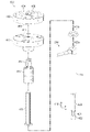
ここで図、詳細には図1を参照するに、データ取得システムの図が、一実施例により、ブロック図の形式で示されている。この実施例では、データ取得システム100は、被加工物についての情報を取得するために使用されうる。
Here, with reference to FIG. 1 for details, a diagram of the data acquisition system is shown in the form of a block diagram, according to an embodiment. In this embodiment, the
図示しているように、データ取得システム100はロボット102を含む。ロボット102は、エンドエフェクタユニット104を移動させるよう構成されうる。詳細には、ロボット102は、被加工物の表面に対してエンドエフェクタユニット104を位置付けるために使用されうる。
As shown in the figure, the
一実施例では、ロボット102は関連するロボットアームを備える。この例では、エンドエフェクタユニット104は、ロボット102に関連するロボットアームに取り付けられるように構成される。
In one embodiment, the
本書において、一構成要素が別の構成要素に「関連する」場合、この関連付けは、図示された例における物理的な関連付けである。例えば、ロボットアームなどの第1構成要素は、第2構成要素に固定されること、第2構成要素に接合されること、第2構成要素に装着されること、第2構成要素に溶接されること、第2構成要素に留め付けられること、第2構成要素に磁気によって取り付けられること、及び/又は、他の何らかの好適な様態で第2構成要素に接続されることによって、ロボット102などの第2構成要素に関連することになると見なされうる。場合によっては、第1構成要素は、第3構成要素によって第2構成要素に接続されることにより、第2構成要素に関連すると見なされうる。第1構成要素は、第2構成要素の一部として、及び/又は延長部として形成されることによって、第2構成要素に関連することになるとも見なされうる。
In this document, where one component is "related" to another, this association is a physical association in the illustrated example. For example, a first component, such as a robot arm, is fixed to the second component, joined to the second component, attached to the second component, and welded to the second component. That, being fastened to the second component, being magnetically attached to the second component, and / or being connected to the second component in some other suitable manner, such as the
図示しているように、データ取得システム100はロボットコントローラ106を含む。ロボットコントローラ106は、ロボット102の移動を制御するよう構成されうる。詳細には、ロボットコントローラ106は、被加工物の表面に対してエンドエフェクタユニット104を位置付けるために、ロボット102を制御するのに使用されうる。
As shown in the figure, the
図示しているように、データ取得システム100はデータ取得コントローラ108を含む。データ取得コントローラ108は、エンドエフェクタユニット104の動作を制御するよう構成されうる。詳細には、データ取得コントローラ108は、被加工物についての情報を取得するために、エンドエフェクタユニット104の動作を制御するのに使用されうる。
As shown in the figure, the
一実施例では、データ取得コントローラ108は、被加工物についてのデータを取得するためのモジュールである。この実施例では、データ取得コントローラ108は、内部でそれ自体の制御プログラムを実行するわけではない。その代わりに、データ取得コントローラ108は、ロボットコントローラ106又はアプリケーションコントローラ114の少なくとも一方に、入力/出力の生データを提供する。
In one embodiment, the
一実施例では、データ取得コントローラ108は、ロボットコントローラ106によって制御されうるか、又はロボットコントローラ106に統合されうる、モジュールである。したがって、データ取得コントローラ108は、ロボットコントローラ106と直接通信するモジュールでありうる。
In one embodiment, the
別の実施例では、データ取得コントローラ108は、アプリケーションコントローラ114によって制御されうる。したがって、データ取得コントローラ108は、アプリケーションコントローラ114を通じて、エンドエフェクタユニット104と連動しうる。
In another embodiment, the
この実施例では、データ取得システム100は、ロボットコントローラ106、データ取得コントローラ108、及びアプリケーションコントローラ114を含む。ロボットコントローラ106、データ取得コントローラ108、及びアプリケーションコントローラ114のうちの少なくとも1つは、ソフトウェア、ハードウェア、ファームウェア、又はそれらの組み合わせを使用して実装されうる。ソフトウェアを使用する場合、ロボットコントローラ106、データ取得コントローラ108、及びアプリケーションコントローラ114によって実施される動作は、限定するわけではないが例としては、プロセッサユニットで実行されるよう設定されたプログラムコードを使用して、実装されうる。ファームウェアを使用する場合、ロボットコントローラ106及びデータ取得コントローラ108によって実施される動作は、限定するわけではないが例としては、プロセッサユニットで実行されるよう不揮発性メモリに記憶されたプログラムコード及びデータを使用して、実装されうる。
In this embodiment, the
ハードウェアが用いられる場合、ハードウェアは、ロボットコントローラ106及びデータ取得コントローラ108によって実施される動作を実施するよう動作する、一又は複数の回路を含みうる。実行形態に応じて、ハードウェアは、回路システム、集積回路、特定用途向け集積回路(ASIC)、プログラマブル論理デバイス、又は、任意の数の動作を実施するよう構成された、他の何らかの好適な種類のハードウェアデバイスの形態をとりうる。
When hardware is used, the hardware may include one or more circuits that operate to perform the operations performed by the
プログラマブル論理デバイスは、特定の動作を実施するように構成されうる。このデバイスは、これらの動作を実施するよう恒久的に構成されうるか、又は、再構成可能でありうる。プログラマブル論理デバイスは、限定するわけではないが例としては、プログラマブル論理アレイ、プログラマブルアレイ論理、フィールドプログラマブル論理アレイ、フィールドプログラマブルゲートアレイ、又は、他の何らかの種類のプログラマブルハードウェアデバイスの形態をとりうる。 The programmable logic device may be configured to perform a particular operation. The device may be permanently configured or reconfigurable to perform these operations. Programmable logic devices can take, but are not limited to, in the form of programmable logic arrays, programmable array logic, field programmable logic arrays, field programmable gate arrays, or some other type of programmable hardware device.
本書において、列挙されたアイテムと共に使用される「のうちの少なくとも1つ(at least one of)」という表現は、列挙されたアイテムのうちの一又は複数の種々の組み合わせが使用可能であり、必要とされうるのは列挙されたアイテムのうち1つだけであることを、意味している。アイテムとは、特定の対象物、物品、ステップ、動作、プロセス、又はカテゴリでありうる。換言すると、「のうちの少なくとも1つ」は、アイテムの任意の組み合わせ、又はいくつかのアイテムがリストから使用されうることを意味するが、列挙されたアイテムの全てが必要とされるわけではない。 In this document, the expression "at least one of" used with the listed items allows and requires various combinations of one or more of the listed items. It means that only one of the listed items can be considered. An item can be a particular object, article, step, action, process, or category. In other words, "at least one of" means that any combination of items, or some items, can be used from the list, but not all of the listed items are required. ..
限定するわけではないが例としては、「アイテムA、アイテムB、若しくはアイテムCのうちの少なくとも1つ」又は「アイテムA、アイテムB、及びアイテムCのうちの少なくとも1つ」とは、「アイテムA」、「アイテムAとアイテムB」、「アイテムB」「アイテムA、アイテムB、及びアイテムC」、「アイテムBとアイテムC」、又は、他の何らかの種類の組み合わせを意味しうる。場合によっては、「アイテムA、アイテムB、若しくはアイテムCのうちの少なくとも1つ」又は「アイテムA、アイテムB、及びアイテムCのうちの少なくとも1つ」とは、限定するわけではないが、「2つのアイテムA、1つのアイテムB、及び、10のアイテムC」、「4つのアイテムB及び7つのアイテムC」、又は、他の何らかの好適な組み合わせを意味しうる。 As an example, but not limited to, "at least one of item A, item B, or item C" or "at least one of item A, item B, and item C" is "item. It can mean "A", "Item A and Item B", "Item B", "Item A, Item B, and Item C", "Item B and Item C", or some other combination of types. In some cases, "at least one of item A, item B, or item C" or "at least one of item A, item B, and item C" is, but is not limited to, ". It can mean "two items A, one item B, and ten items C", "four items B and seven items C", or any other suitable combination.
この実施例では、データ取得システム100はエンドエフェクタユニット104を含む。エンドエフェクタユニット104は、ロボット102に取り付けられるように構成される。この実施例では、エンドエフェクタユニット104は、ロボット102に関連するロボットアームに取り付けられるように構成される。
In this embodiment, the
エンドエフェクタユニット104は、被加工物についての情報を取得するよう構成される。この情報は、例えば、被加工物の寸法などの被加工物の物理的特性に関する情報でありうる。一実施例では、エンドエフェクタユニット104は、被加工物の厚さを測定するよう構成される。
The
一実施例では、エンドエフェクタユニット104は、受動適応型である。エンドエフェクタユニット104のこの受動適応により、エンドエフェクタユニット104が非理想的な条件に適合し、なおかつ、データ取得コントローラ108からのプログラムされた制御を実施することが、可能になる。非理想的な条件に適合する能力により、データ取得コントローラ108が、被加工物における公称の被加工物フィーチャ位置向けに開発されたロボット応用形態を、被加工物フィーチャの極端ではない位置不一致を伴う状況に適合させることが、可能になる。このロボット応用形態は、ロボットコントローラ106を別経路に再プログラミングすること、又は、完了したプログラムを部分的にさかのぼって被加工物若しくはロボットの位置の調整を行うことを必要とせずに、適合可能である。
In one embodiment, the
一実施例では、エンドエフェクタユニット104の受動適応は、エンドエフェクタユニット104に統合された複数の並進式接合部及び回転式接合部を通じて、実装される。この実施例では、並進式接合部及び回転式接合部は、エンドエフェクタユニット104が非理想的な条件に受動的に適合し、なおかつ、データ取得コントローラ108からのプログラムされた制御を実施することを可能にする、磁気デテント及びばねを備える。受動適応運動が行われている間に、接触及び不具合を検出又は判定するためにセンサ112が使用され、この検出又は判定は次いで、ロボットコントローラ106に通信される。
In one embodiment, the passive adaptation of the
エンドエフェクタユニット104はいくつかの構成要素を含む。図示しているように、エンドエフェクタユニット104は、測定プローブ110及びセンサ112を含む。
The
測定プローブ110は、被加工物についての情報を取得するよう構成されたツールである。一実施例では、測定プローブ110は、特定の位置において被加工物の表面厚さを正確に測定するよう構成された、作動するリニア測定プローブである。
The measuring
一実施例では、測定プローブ110は被加工物に接触するよう構成される。測定プローブ110は、接触適応型であってよく、エンドエフェクタユニット104又は被加工物に損傷をもたらすことのない被加工物との軽い接触を許容する。エンドエフェクタ104は、接触の発生に応じてつながり(articulate)、次いで、接触がなくなるとその当初の構成に戻るよう、設計される。
In one embodiment, the measuring
センサ112は、測定プローブ110と被加工物との接触を検出するよう構成される。測定プローブ110と被加工物との接触を検出することにより、被加工物フィーチャと測定プローブ110の接触位置合わせが可能になる。測定プローブ110の接触位置合わせにより、ロボットコントローラ106を別経路に再プログラミングすること、又は、完了したプログラムを部分的にさかのぼって被加工物若しくはロボットの位置の調整を行うことを必要とせずに、ロボット102が、公称の被加工物フィーチャ位置と実際の被加工物フィーチャ位置との間に位置不一致を伴う非理想的な条件に適合することが可能になる。
The
図示しているように、データ取得システム100はアプリケーションコントローラ114を含む。一実施例では、アプリケーションコントローラ114は、1つのコンピュータ、又は、互いに通信可能な複数のコンピュータからなる、コンピュータシステムの中で実装される。一実施例では、アプリケーションコントローラ114によって実施されるステップを実施するための指令すなわちコードが、コンピュータシステムのメモリに記憶され、かつ、このコンピュータシステムの中の一又は複数のプロセッサによって実装されうる。
As shown, the
この実施例では、アプリケーションコントローラ114は、ロボットコントローラ106及びデータ取得コントローラ108と連動する。ユーザは、アプリケーションコントローラ114のユーザインターフェース116を通じて、ロボットコントローラ106とデータ取得コントローラ108の少なくとも一方と対話しうる。
In this embodiment, the
図1のデータ取得システム100の図は、実施例が実装されうる様態に、物理的な又は構造上の制限を課すことを意図するものではない。図示した構成要素に加えて、又はそれらに代えて、他の構成要素が使用されうる。一部の構成要素は不要になりうる。また、一部の機能する構成要素を図示するために、ブロックが提示されている。実施例において実装される場合、これらのブロックのうちの一又は複数が、組み合わされ、分割され、又は、組み合わされて異なるブロックに分割されうる。
The figure of the
例えば、場合によっては、データ取得コントローラ108は、ロボットコントローラ106の一部として、又はアプリケーションコントローラ114として、実装されうる。それ以外の場合、アプリケーション114とデータ取得コントローラ108の両方が、ロボットコントローラ106の一部として実装されうる。
For example, in some cases, the
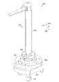
次に図2を参照するに、エンドエフェクタユニットが取り付けられているロボットの斜視図が、一実施例により示されている。ロボット202は、図1にブロック形式で示したロボット102の物理的実行形態の一例でありうる。
Next, with reference to FIG. 2, a perspective view of the robot to which the end effector unit is attached is shown by one embodiment. The
一実施例では、ロボット202は、エンドエフェクタユニット204を移動させるよう構成されうる。詳細には、ロボット202は、被加工物の表面に対してエンドエフェクタユニット204を位置付けるために使用されうる。図示しているように、ロボット202はロボットアームを備える。
In one embodiment, the
この実施例では、エンドエフェクタユニット204は、ロボット202に取り付けられるように構成される。図2に示すエンドエフェクタユニット204は、図1にブロック形式で示したエンドエフェクタユニット104の物理的実行形態の一例でありうる。エンドエフェクタユニット204は、被加工物についての情報を取得するよう構成される。
In this embodiment, the
一実施例では、エンドエフェクタユニット204は、受動適応型である。エンドエフェクタユニット204は、被加工物及び被加工物フィーチャの極端ではない位置不一致を伴う非理想的な条件に適合しうる。非理想的な条件に適合する能力により、ロボット202を別経路に再プログラミングすること、又は、ロボット202の位置の調整を行うことを必要とせずに、エンドエフェクタユニット204が、被加工物及び被加工物フィーチャに関する極端ではない位置不一致に適合することが可能になる。
In one embodiment, the
一実施例では、エンドエフェクタユニット204は測定プローブ206を含む。図2に示す測定プローブ206は、図1にブロック形式で示した測定プローブ110の物理的実行形態の一例でありうる。この実施例では、エンドエフェクタユニット204は、接触適応型に構成され、エンドエフェクタユニット204又は被加工物に損傷をもたらすことのない被加工物との軽い接触を許容する。
In one embodiment, the
測定プローブ206は被加工物に接触するよう構成される。この実施例では、測定プローブ206は、被加工物及び被加工物フィーチャに接触して位置合わせされるよう構成される。測定プローブ206の接触位置合わせにより、ロボット202の再プログラミングを必要とせずに、エンドエフェクタユニット204が、位置不一致を伴う非理想的な条件に適合することが可能になる。
The measuring
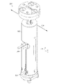
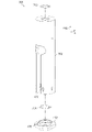
次に図3を参照するに、エンドエフェクタユニットの正射投影図が一実施例により示されている。図示しているように、図3は図2のエンドエフェクタユニット204の拡大図である。
Next, with reference to FIG. 3, an orthographic projection of the end effector unit is shown by one embodiment. As shown, FIG. 3 is an enlarged view of the
図示しているように、エンドエフェクタユニット204は、測定プローブ206、本体302、及び脚部アセンブリ304を含む。測定プローブ206は、本体302及び脚部アセンブリ304の中に装着される。脚部アセンブリ304は本体302に関連しており、それにより、脚部アセンブリ304及び測定プローブ206は、受動適応型となり、エンドエフェクタユニット204が被加工物フィーチャの非理想的な位置に適合することを可能にする。
As shown, the
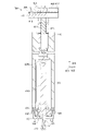
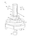
次に図4を参照するに、エンドエフェクタユニットの断面図が一実施例により示されている。図示しているように、図4は図3の線306に沿って切った、エンドエフェクタユニット204の断面図である。
Next, with reference to FIG. 4, a cross-sectional view of the end effector unit is shown by one embodiment. As shown, FIG. 4 is a cross-sectional view of the
図示しているように、エンドエフェクタユニット204はコネクタプレート402を含む。コネクタプレート402は、エンドエフェクタユニット204を図2のロボット202に接続する。一実施例では、コネクタプレート402は、コネクタプレート402と磁気分離部(breakaway)410との断接を検出するための、マイクロスイッチ分離部404を含む。一実施例では、マイクロスイッチ分離部404は、コネクタプレート402が磁気分離部410から断接状態になった場合の安全機構として、緊急停止条件を作動させる。
As shown, the
コネクタプレート402は、埋め込まれた磁石406及び運動ロケータ408を含む。埋め込まれた磁石406及び運動ロケータ408は、コネクタプレート402に磁気分離部410を精密に連結する。
The
一実施例では、運動ロケータ408は、磁気分離部410のくぼみ411に対応する、コネクタプレート402に三角形に配置された3つの突起である。コネクタプレート402が磁気分離部410に連結されている時、運動ロケータ408は、コネクタプレート402と磁気分離部410との相対運動を、6自由度において確定的に制約する。
In one embodiment, the
リニア摺動部412が、スプライン413を通じて磁気分離部410に装着される。一実施例では、ばね414が、z軸416に沿った適応を提供し、エンドエフェクタユニット204と被加工物との軽い接触を許容する。ばね414は、後述する他の特徴と併用されて、測定プローブ206の受動的な接触位置合わせを可能にし、エンドエフェクタユニット204が、非理想的な条件のもとで被加工物フィーチャに関する正確な情報を取得することを可能にする。
The linear sliding
リニア摺動部412の適応特性により、本体302がz軸416に沿って移動することが可能になる。後述する他の特徴と併用されて、リニア摺動部412が、コネクタプレート402及び磁気分離部410に対してz軸416に沿って延在することで、被加工物及び被加工物フィーチャ非理想的な位置の補償が可能になる。具体的にはリニア摺動部412は、被加工物フィーチャの角度的な位置ずれを部分的に補償し、かつ、測定プローブ206による正確なデータ取得を可能にする。
The adaptive characteristics of the linear sliding
リニアゲージ418が、位置合わせ磁石420a及び420bによって、リニア摺動部412に磁気的に連結される。リニア摺動部412との磁気連結は、後述する他の特徴と併用されて、ユニットが被加工物フィーチャの非理想的な位置を補償するために公称配向から離れるように動いた後に、リニアゲージ418が公称配向に戻ることを可能にする。具体的には、リニア摺動部412とリニアゲージ418との磁気連結は、被加工物フィーチャの角度的な位置ずれを部分的に補償し、測定プローブ206が被加工物フィーチャのこの角度的な位置ずれに位置合わせされることを可能にする。リニア摺動部412とリニアゲージ418との磁気連結に部分的に基づいて、エンドエフェクタ204は、非理想的な条件のもとでも被加工物フィーチャに関する正確な情報が取得可能であり、かつ、情報の取得が終わるとニュートラルな状態に戻りうる。
The
リニアゲージ408は、被加工物についての情報を測定するよう設計されたセンサである。この情報は、例えば、厚さ、曲率、偏心度、変位、高さ、深さ、平坦度、変動、振れ(runout)、真円度、ゆがみ、反り、又は配置でありうる。一実施例では、リニアゲージ418は、z軸416に沿った接触子422の動きの範囲に基づいて、被加工物フィーチャにおいて被加工物の厚さを判定するよう構成される。リニアゲージ418は、被加工物において被加工物の厚さを判定するよう構成されている場合、例えば、エンコーダベースの測定プローブ、直線的に変動可能な差動トランス、又は、他の好適な種類の距離測定デバイスでありうる。
The
一実施例では、接触子422の伸長は、伸長シャフト421を通じて接触子422に接続された空圧アクチュエータによって、作動する。この実施例では、空圧アクチュエータは、測定プローブ206の中の空圧シリンダによって駆動される。接触子422の空圧作動は、z軸416に沿った追加的な適応を提供する。
In one embodiment, the extension of the
別の実施例では、接触子422の伸長は、例えば親ねじアクチュエータなどの他の種類のアクチュエータによって作動する。この実施例では、そのような他の種類のアクチュエータは、z軸416に沿った追加的な適応を提供するために、それ自体の内部にばねシステムを有しうる。
In another embodiment, the extension of the
z軸416に沿った並進とピッチ/ロール回転との同時適応により、測定プローブ206の受動的な自己位置合わせと共に、エンドエフェクタユニット204の横方向運動のオーバートラベル補償が、可能になる。エンドエフェクタユニット204は、測定プローブ206の自己位置合わせに部分的に基づいて、非理想的な条件のもとでも被加工物フィーチャに関する正確な情報を取得しうる。
Simultaneous adaptation of translation and pitch / roll rotation along the z-
並進式接合部(424、426)の一例は、エンドエフェクタ204の脚部コレット424の中に摺動可能に固定された、軸受ハウジング426である。この脚部コレット424は、軸受ハウジング426の周りにカラーを形成する。軸受ハウジング426は、球面軸受428の周囲で、脚部コレット424内で回転可能であり、軸受ハウジング426及び本体302に対する脚部コレット424の回転移動を可能にする。回転式接合部(426、428)の一例は、エンドエフェクタ204の軸受ハウジング426内に回転可能に装着された、球面軸受428である。
An example of a translational joint (424, 426) is a bearing
球面軸受428はリニアゲージ418を支持する。球面軸受428は、球面軸受428の周囲の直角方向における中心点の周囲での、リニアゲージ418の角度回転を許容する。
The
直角方向における、球面軸受428の周囲での測定プローブ206の角度適応により、測定プローブ206の受動的な自己位置合わせが可能になる。エンドエフェクタユニット204は、測定プローブ206の自己位置合わせに部分的に基づいて、非理想的な条件のもとでも被加工物フィーチャに関する正確な情報を取得しうる。
The angular adaptation of the measuring
軸受ハウジング426は、位置合わせ磁石430及び位置合わせ磁石432によって、本体302に磁気的に連結される。位置合わせ磁石430及び位置合わせ磁石432は、後述する他の特徴と併用されて、エンドエフェクタユニット204が被加工物フィーチャの非理想的な位置を補償することを可能にする。具体的には、位置合わせ磁石430と位置合わせ磁石432との磁気連結は、被加工物フィーチャの平面的な位置ずれを部分的に補償し、測定プローブ206が平面的に並進して被加工物及び被加工物フィーチャに位置合わせされることを可能にする。位置合わせ磁石430は軸受ハウジング426の位置合わせ磁石432と相互作用し、磁気デテントとして作用する。軸受ハウジング426と本体302との磁気連結に部分的に基づいて、エンドエフェクタユニット204は、非理想的な条件のもとでも被加工物フィーチャに関する正確な情報が取得可能であり、かつ、状態の取得が終わるとニュートラルな状態に戻りうる。
The bearing
バレルプローブ423は、エンドエフェクタユニット204の、ロボット202によるエンドエフェクタ204の横方向運動中に接触フィードバックを提供するよう構成された部分である。一実施例では、バレルプローブ423は、図1にブロック形式で示したロボットコントローラ106にデジタル信号を送信するよう構成された、集約型(integrated)接触感知性能を含む。バレルプローブ423からの信号は、被加工物との接触、及び、ロボットコントローラ106がロボット102の運動を停止すべきであることを示す。
The
一実施例では、バレルプローブ423の集約型接触感知性能は、図1にブロック形式で示したセンサ112などの一又は複数の接触センサによって提供される。この実施例では、バレルプローブ423の集約型接触感知性能は、限定するわけではないが、圧力ベースのスイッチ、容量性センサ、抵抗性センサ、及び電気接続センサ、並びにそれらの組み合わせなどの、接触センサによって提供されうる。
In one embodiment, the intensive contact sensing performance of the
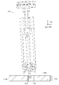
次に図5を参照するに、エンドエフェクタユニットの、測定プローブを含む分解組み立て部の正射投影図が、一実施例により示されている。図5に示すアセンブリ500は、図2のエンドエフェクタユニット204の測定プローブ206並びに他の構成要素の、分解状態の正射投影図である。
Next, with reference to FIG. 5, an orthographic projection of the disassembled assembly of the end effector unit, including the measurement probe, is shown by one embodiment.
図示しているように、アセンブリ500はコネクタプレート402を含む。コネクタプレート402は、エンドエフェクタユニット204をロボット202(両方とも図1に示している)に接続する。一実施例では、コネクタプレート402は、エンドエフェクタユニット204をロボット202に取り外し可能に接続するための、マイクロスイッチ分離部404を含む。
As shown, the
コネクタプレート402は、埋め込まれた磁石406及び運動ロケータ408を含む。運動ロケータ408は、磁気分離部410のくぼみ411に対応し、コネクタプレート402に磁気分離部410を精密に連結する。
The
リニア摺動部412が、スプライン413を通じて磁気分離部410に装着される。一実施例では、ばね414が、z軸416に沿った適応を提供し、被加工物フィーチャの角度的な位置ずれを部分的に補償する。
The linear sliding
リニアゲージ418が、位置合わせ磁石420a及び420bによって、リニア摺動部412に磁気的に連結される。位置合わせ磁石420a及び420bにより、被加工物及び被加工物フィーチャの角度的な位置ずれの部分的な補償が可能になり、被加工物フィーチャの角度的な位置ずれと測定プローブ206とを受動的に位置合わせすることが可能になる。
The
次に図6を参照するに、エンドエフェクタユニットの、脚部アセンブリを含む分解組み立て部の正射投影図が、一実施例により示されている。図6に示す脚部アセンブリ304は、図3のエンドエフェクタユニット204の脚部アセンブリ304並びに他の構成要素の、分解状態の正射投影図である。
Next, with reference to FIG. 6, an orthographic projection of the disassembled assembly of the end effector unit, including the leg assembly, is shown by one embodiment. The
脚部アセンブリ304は脚部コレット424を含む。脚部コレット424は、図4の軸受ハウジング426の周りにカラーを形成する。脚部コレット424は、図8に示す軸受ハウジングが、球面軸受428の周囲で回転することを可能にし、軸受ハウジング426及び本体302に対する脚部コレット424の回転移動を可能にする。
The
脚部コレット424はいくつかの接触子先端602を含む。接触子先端602は、エンドエフェクタユニット204又は被加工物に損傷をもたらすことのない被加工物との軽い接触を許容する。
The
球面軸受428は、球面軸受428の周囲の直角方向における中心点の周囲での、図4に示すリニアゲージ418の角度回転を許容する。球面軸受は428は、ロックナット604によってリニアゲージ418に固定される。クランプ606が、図4の軸受ハウジング426の中に球面軸受428を固定する。
The
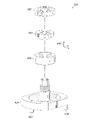
次に図7を参照するに、エンドエフェクタユニットの、本体を含む分解組み立て部の正射投影図が、一実施例により示されている。図7に示すアセンブリ700は、図3のエンドエフェクタユニット204の本体302並びに他の構成要素の、分解状態の正射投影図である。
Next, with reference to FIG. 7, an orthographic projection drawing of the disassembled assembly portion of the end effector unit including the main body is shown by one embodiment. The
本体302は、図2の測定プローブ206用の保護ハウジングと支持構造体、及び、図4のリニア摺動部412と球面軸受ハウジング428との間の接続を提供する。本体302は、図4に示すリニア摺動部412に関連している。一実施例では、リニア摺動部412は、保持リング702によって、本体302の中に固定される。
The
保持リング704が、図4の軸受ハウジング426の中で球面軸受428を保持する。図6に示しているように、クランプ606が、軸受ハウジング426の中に球面軸受428(両方とも図4に示している)を固定する。
The retaining
軸受ハウジング426は、位置合わせ磁石430及び位置合わせ磁石432によって、本体302に磁気的に連結される。位置合わせ磁石430と位置合わせ磁石432との磁気連結が、被加工物フィーチャの直線的な位置ずれを部分的に補償し、測定プローブ206が被加工物及び被加工物フィーチャに直線的に位置合わせされることを可能にする。
The bearing
次に図8を参照するに、エンドエフェクタアセンブリの斜視図が、一実施例により示されている。アセンブリ800は、エンドエフェクタユニット204から本体302が(両方とも図3に示している)取り外されている、エンドエフェクタユニット204の各部分を示している。
Next, with reference to FIG. 8, a perspective view of the end effector assembly is shown by one embodiment.
図示しているように、アセンブリ800は、リニアゲージ418と、球面軸受428の内部に装着された接触子422とを示している。球面軸受428は、リニアゲージ418を支持し、x軸802とy軸804の両方に沿った直角方向における中心点の周囲での、リニアゲージ418の角度回転を許容する。クランプ606が図6に示すロックナット604を固定し、ロックナット604が、軸受ハウジング426の中に球面軸受428を固定する。
As shown, the
脚部コレット424は、軸受ハウジング426の周りにカラーを形成する。軸受ハウジング426は、球面軸受428の周囲で、脚部コレット424内で回転可能であり、軸受ハウジング426に対する脚部コレット424の回転移動を可能にする。
The
次に図9を参照するに、エンドエフェクタアセンブリの拡大正射投影図が、一実施例により示されている。図示しているように、アセンブリ900は、図8のアセンブリ800の下部の拡大された正射投影図である。
Next, with reference to FIG. 9, an enlarged orthographic projection of the end effector assembly is shown by one embodiment. As shown,
次に図10を参照するに、エンドエフェクタアセンブリユニットの断面図が、一実施例により示されている。図示しているように、図10は、図9の断面線902に沿って切った、アセンブリ900の断面図である。図示しているように、接触子422は伸長シャフト421に装着され、伸長シャフト421は、球面軸受428を通過するプローブバレル423の中で摺動する。球面軸受428は、リニアゲージ418を支持し、x軸802とy軸804の両方に沿った直角方向における中心点の周囲での、リニアゲージ418の角度回転を許容する。クランプ606が、軸受ハウジング426の中に球面軸受428を固定する。
Next, with reference to FIG. 10, a cross-sectional view of the end effector assembly unit is shown by one embodiment. As shown, FIG. 10 is a cross-sectional view of
脚部コレット424は、軸受ハウジング426の周りにカラーを形成する。軸受ハウジング426は、球面軸受428の周囲で、脚部コレット424内で回転可能であり、軸受ハウジング426に対する脚部コレット424の回転移動を可能にする。
The
次に図11を参照するに、被加工物と角度的に位置ずれしている、受動適応型エンドエフェクタユニットの断面図が、一実施例により示されている。図示しているように、エンドエフェクタ204は、図4の断面図に従って示されている。
Next, referring to FIG. 11, a cross-sectional view of a passively adaptive end effector unit that is angularly displaced from the workpiece is shown by one embodiment. As shown, the
この実施例では、エンドエフェクタ204は、被加工物1104の被加工物フィーチャ1102に動作を実施するよう位置付けられる。この実施例では、動作は、被加工物1104の厚さ1106の測定である。
In this embodiment, the
この実施例では、被加工物1104は航空機の部品でありうる。限定するわけではないが例としては、被加工物1104は、外板パネル、翼、胴体、水平安定板、ドア、ハウジング、エンジン、又は航空機内の他の好適な構造体のうちの、少なくとも一つに組み込まれうる。被加工物1104は、リブ、スパー、ストリンガ、又は航空機内の他の好適なフレーム構造体といった、航空機のフレーム構造体でもありうる。
In this embodiment, the
被加工物1104は表面1108を有しうる。表面1108は、一部の実施例では、「作業面(work surface)」と称されうる。被加工物1104の被加工物フィーチャ1102は、実際の位置1110に配置される。
The
この実施例では、被加工物フィーチャ1102は被加工物1104のフィーチャであり、この被加工物1104のフィーチャに、エンドエフェクタユニット204によって動作が実施される。この実施例では、被加工物フィーチャ1102は被加工物1104の穴である。この実施例では、エンドエフェクタユニット204は、被加工物1104の厚さの測定動作を正確に実施するよう構成される。
In this embodiment, the
エンドエフェクタユニット204は、図1にブロック形式で示したロボットコントローラ106に従って公称位置に、図2のロボット202により位置付けられる。公称位置は、表面1108に沿った、被加工物1104及び被加工物フィーチャ1102の予期される位置及び配向に対応する。公称位置は、被加工物1104の設計又は製造仕様に基づくものでありうる。公称位置は、ロボットコントローラ106とアプリケーションコントローラ114の少なくとも一方の中に、基準データ(reference data)として記憶されうる。
The
この実施例では、被加工物1104の実際の位置1110は、実質的に、エンドエフェクタユニット204が配向された公称位置から、角度的にずれている。このような動作条件のもとでは、エンドエフェクタユニット204は、エンドエフェクタユニット204と被加工物1104との間の角度的な位置ずれにより、被加工物フィーチャ1102に正確に動作を実施できないことがある。
In this embodiment, the
本書において、「およそ(approximately)」、「約(about)、及び「実質的に(substantially)」という用語は、依然として所望の機能を実施しうるか、又は所望の結果を実現しうる、規定された量に近い量を表す。例えば、「およそ」、「約」、及び「実質的に」という用語は、規定の量の、10%未満以内、5%未満以内、1%未満以内、0.1%未満以内、及び、0.01%未満以内の量を表しうる。 In this book, the terms "approximately", "about", and "substantially" are defined as still capable of performing the desired function or achieving the desired result. Represents a quantity close to the quantity. For example, the terms "approximately," "about," and "substantially" refer to the prescribed amount of less than 10%, less than 5%, less than 1%, less than 0.1%, and 0. Can represent an amount of less than 0.01%.
次に図12を参照するに、被加工物が角度的に位置ずれしている受動適応型エンドエフェクタユニットの位置合わせに関する断面図が、一実施例により示されている。図示しているように、図4の断面図に従って示されているエンドエフェクタ204は、図11の被加工物フィーチャ1102に、受動的に位置合わせされる。
Next, with reference to FIG. 12, a cross-sectional view relating to the alignment of the passive adaptive end effector unit in which the workpiece is angularly displaced is shown by one embodiment. As shown, the
球面軸受428は、本体302に対する、球面軸受428の周囲の直角方向における中心点の周囲での、リニアゲージ418及び脚部コレット242の角度回転を許容する。接触子422が被加工物フィーチャ1102内に挿入されるにつれて、脚部コレット424は、球面軸受428の周囲で受動的に回転し、軸受ハウジング426及び本体302に対する脚部コレット424の回転移動を可能にする。
The
測定プローブ206のリニアゲージ418は、脚部コレット424に連結される。したがって、球面軸受428の周囲での脚部コレット424の回転により、それに対応する、x軸802とy軸804に沿った直角方向における測定プローブ206の回転が発生する。
The
直角方向における、球面軸受428の周囲での測定プローブ206の角度適応により、エンドエフェクタユニット204の受動的で角度的な自己位置合わせが可能になる。エンドエフェクタユニット204は、測定プローブ206の受動的な自己位置合わせに部分的に基づいて、被加工物フィーチャ1102に正確に動作を実施しうる。
The angular adaptation of the measuring
次に図13を参照するに、被加工物と角度的に位置ずれしている受動適応型エンドエフェクタユニットの断面図が、一実施例により示されている。図示しているように、エンドエフェクタ204は、図4の断面図に従って示されている。
Next, with reference to FIG. 13, a cross-sectional view of the passive adaptive end effector unit that is angularly displaced from the workpiece is shown by one embodiment. As shown, the
この実施例では、エンドエフェクタユニット204は、被加工物1104の被加工物フィーチャ1302に動作を実施するよう位置付けられる。この実施例では、動作は、被加工物1104の厚さ1106の測定である。
In this embodiment, the
エンドエフェクタユニット204は、図1にブロック形式で示したロボットコントローラ106よる穴の公称位置の上方の位置に、図2のロボット202によって位置付けられる。公称位置は、表面1108に沿った、被加工物1104及び被加工物フィーチャ1302の予期される位置に対応している。公称位置は、被加工物1104の設計又は製造仕様に基づくものでありうる。公称位置は、ロボットコントローラ106とアプリケーションコントローラ114の少なくとも一方の中に、基準データとして記憶されうる。この実施例では、公称位置は、被加工物フィーチャ1102の中心の、三次元配置及び角度配向を含む予期される位置である。
The
この実施例では、被加工物1104の実際の位置1310は、実質的に、エンドエフェクタユニット204が配置される公称位置から、直線的にずれている。このような動作条件のもとでは、エンドエフェクタユニット204は、エンドエフェクタユニット204と被加工物フィーチャ1302との間の直線的な位置ずれにより、被加工物フィーチャ1302に正確に動作を実施できないことがある。
In this embodiment, the
次に図14を参照するに、被加工物が直線的に位置ずれしている、受動適応型エンドエフェクタユニットの受動位置合わせに関する断面図が、一実施例により示されている。図示しているように、図4の断面図に従って示されているエンドエフェクタ204は、図13の被加工物フィーチャ1302に受動的に位置合わせされる。
Next, with reference to FIG. 14, a cross-sectional view relating to the passive alignment of the passive adaptive end effector unit in which the workpiece is linearly misaligned is shown by one embodiment. As shown, the
被加工物1104の実際の位置1310が、実質的に、エンドエフェクタユニット204が配置される公称位置から直線的にずれている場合、軸受ハウジング426が、フィーチャ1302の実際の位置の位置ずれに適合するために、実質的にニュートラルな位置から受動的に変位する。この実施例では、軸受ハウジング426は、本体302に対して、x軸802とy軸804のいずれに沿っても並進しうる。
If the
軸受ハウジング426は、位置合わせ磁石430及び位置合わせ磁石432によって、本体302に磁気的に連結される。接触子422が被加工物フィーチャ1302内に挿入されるにつれて、位置合わせ磁石430と位置合わせ磁石432はオフセットし、エンドエフェクタユニット204が被加工物フィーチャの非理想的な位置を補償することを可能にする。軸受ハウジング426は、本体302に対して受動的にオフセットし、本体302に対する軸受ハウジング426の直線的な移動を可能にする。
The bearing
測定プローブ206のリニアゲージ418は、軸受ハウジング426に連結される。したがって、軸受ハウジング426の直線的な変位により、それに対応する測定プローブ206のオフセットが発生する。
The
本体302に対する軸受ハウジング426の移動に基づく測定プローブ206の直線的適応は、被加工物フィーチャの直線的な位置ずれを部分的に補償し、測定プローブ206が被加工物及び被加工物フィーチャに直線的に位置合わせされることを可能にする。測定プローブ206の直線的適応により、エンドエフェクタユニット204の受動的で直線的な自己位置合わせが可能になる。エンドエフェクタユニット204は、測定プローブ206の受動的な自己位置合わせに部分的に基づいて、被加工物フィーチャ1302に正確に動作を実施しうる。
The linear adaptation of the measuring
次に図15から図22を参照するに、動作を実施している受動適応型エンドエフェクタの一連の正射投影断面図が、一実施例により示されている。図示しているように、被加工物1500に動作を実施しているエンドエフェクタユニット204が示されている。この実施例では、動作は、被加工物フィーチャ1502における被加工物1504の厚さ1506の測定である。この実施例では、被加工物フィーチャ1502は穴1508である。
Next, with reference to FIGS. 15 to 22, a series of orthographic projection cross-sectional views of the passive adaptive end effector performing the operation is shown by one embodiment. As shown, the
ここで、具体的には図15を参照するに、エンドエフェクタユニット204は、図1にブロック形式で示したロボットコントローラ106に従って、図2のロボット202により接近位置1510に位置付けられる。接近位置1510は、穴1508の公称位置の若干上方の位置である。接近位置1510は、接触子422が被加工物1504に当たることなく穴1508内に伸長しうるように、被加工物の上方一定の高さに位置付けられる。
Here, specifically referring to FIG. 15, the
ここで、具体的には図16を参照するに、被加工物1504の近位にあるが接触していない、エンドエフェクタユニット204が示されている。図1にブロック形式で示したロボットコントローラ106がエンドエフェクタユニット204の移動を終了すると、図1にブロック形式で示したデータ取得コントローラ108は、被加工物1504の表面1512との接触をチェックするために、測定プローブ206の接触子422を伸長させる。測定プローブ206の接触子422が完全に伸長すると、図1にブロック形式で示したデータ取得コントローラ108は、測定プローブ206が穴1508の中に伸長したと推定する。
Here, specifically, with reference to FIG. 16, shows the
測定プローブ206が完全に伸長できない場合、データ取得コントローラ108は、接触子422が表面1512に接触したと推定する。図1にブロック形式で示したアプリケーションコントローラ144は、次いで、下記の図24に示す大位置ずれ軽減プロセスに進む。
If the
ここで、具体的には図17を参照するに、接触子422が、測定深さ1802まで、穴1508の中心を通って下に移動するように、エンドエフェクタユニット204は、図1にブロック形式で示したロボット102によって動かされる。
Here, specifically referring to FIG. 17, the
この実施例では、エンドエフェクタユニット204の垂直適応が、被加工物1504及びエンドエフェクタユニット204への損傷を防止する。垂直適応は、例えばばね414の圧縮によって提供されうる。
In this embodiment, the vertical adaptation of the
接触子422が穴1508の中に移動するにつれて、測定プローブ206は、受動的に配向されて、穴1508の実際の位置1514に位置合わせされる。この実施例では、測定プローブ206が、図11から図14に関連して上述したように、穴1508の実際の位置1514に、受動的に位置合わせされる。
As the
ここで、具体的には図18を参照するに、測定プローブ206が穴1508の中に移動し、穴1508と受動的に位置合わせされた後、エンドエフェクタ204は測定位置1802に移動する。この実施例では、測定位置1802は穴1508の周縁の周辺の位置であり、この位置において、被加工物1504の厚さ1506が判定される。測定位置1802に到達するために、図1にブロック形式で示したロボットコントローラ106は、図2のロボットを方向付けて、測定プローブ110が測定位置1802において被加工物1504に接触するまで、エンドエフェクタユニット204をx軸802とy軸804の少なくとも一方に沿った方向に移動させる。
Here, specifically referring to FIG. 18, after the
一実施例では、上記の図8から図11に関連して上述した適応要素は、測定位置1802のオーバーランを受け入れるよう変位する。上記の図8から図11に関連して上述したように、エンドエフェクタユニット204が測定位置1802をオーバーランした場合、軸受ハウジング426が、エンドエフェクタユニット204による測定位置1802のオーバーランを補償するために、本体802に対して受動的に変位する。ロボットコントローラ106が移動を停止させるべきであることを示すために、バレルプローブ423からの接触信号が、ロボットコントローラ106に送信される。たとえ接触が発生したという信号をロボットが受信しても、ロボットが停止に至るには数分の1秒かかる。エンドエフェクタの受動的なX、Y適応が、この動きに対する適応補償を提供する。図18に示しているように、軸受ハウジング426は、x軸802とy軸804のいずれか、又はその両方に沿って、本体302に対して並進する。
In one embodiment, the adaptive elements described above in connection with FIGS. 8 to 11 above are displaced to accept an overrun of
ここで、具体的には図19を参照するに、エンドエフェクタユニット204は、測定位置1802に既に移動している。エンドエフェクタユニット204が測定位置1802に到達すると、図1にブロック形式で示したデータ取得コントローラ108が、測定動作を実施するために測定プローブ206を方向付ける。図示しているように、測定プローブ206は、接触子422が被加工物1504に接触するまで後退する。図1にブロック形式で示したデータ取得コントローラ108は、リニアゲージ418の伸長を特定し、この伸長から、測定位置1802における被加工物1504の厚さ1506が判定されうる。
Here, specifically referring to FIG. 19, the
ここで図20を参照するに、接触子422は伸長した状態で示されており、エンドエフェクタユニット204は、穴1508の公称中心に戻っている。個々の測定が完了すると、図1にブロック形式で示したロボットコントローラ106は、次いで、追加の測定を実施するために、穴1508の周りの異なる測定位置にエンドエフェクタユニット204を移動させうる。穴1508の周りの測定位置の各々について測定プロセスが完了した後、エンドエフェクタユニット204は穴1508の公称中心に戻る。
Here, with reference to FIG. 20, the
ここで図21を参照するに、接触子422は後退している。図1にブロック形式で示したロボットコントローラ106のエンドエフェクタユニット204の移動が終了すると、図1にブロック形式で示したデータ取得コントローラ108は、完全な後退が行われたか否か、又は、接触子422が被加工物1504に接触したか否かを判定するために、接触子422を後退させ、プローブの伸長距離をチェックする。
Here, referring to FIG. 21, the
接触子422が完全には後退できない場合、接触子422は、後退中に被加工物1504に接触している。図1にブロック形式で示したアプリケーションコントローラ144は、下記の図25に示す大位置ずれ軽減プロセスに進む。
If the
ここで図22を参照するに、接近位置に戻ったエンドエフェクタユニット204が示されている。接触子422の通り抜け(clearance)が確認されると、図1にブロック形式で示したロボットコントローラ106は、被加工物1504から離れて接近位置1510に戻るように、エンドエフェクタユニット204を移動させる。図1にブロック形式で示したロボットコントローラ106は、次いで、別の被加工物フィーチャの上方の次の接近位置へとエンドエフェクタユニット204を移動させ、その被加工物フィーチャに動作を実施しうる。
Here, with reference to FIG. 22, the
ここで図23を参照するに、エンドエフェクタユニットの二次元図が別の実施例により示されている。図23に示すエンドエフェクタユニット2302は、図1にブロック形式で示したエンドエフェクタユニット104の物理的実行形態の第2の例である。
Here, with reference to FIG. 23, a two-dimensional diagram of the end effector unit is shown by another embodiment. The
図示しているように、測定プローブ2304が本体2306の外部に配置されている。この実施例では、エンドエフェクタ2302は、被加工物2314の縁部2312に沿って、厚さ2310の測定動作を正確に実施するよう構成される。
As shown, the measuring
ここで図24を参照するに、伸長探索プロセスの実施に関する正射投影図が、一実施例により示されている。図示しているように、伸長探索プロセス2400は、接近位置1510において接触子422の伸長が被加工物1504によって妨げられた場合に被加工物フィーチャを位置特定するための、大位置ずれ軽減プロセスである。
Here, with reference to FIG. 24, an orthographic projection of the implementation of the extension search process is shown by one embodiment. As shown, the
図示しているように、エンドエフェクタユニット204は、図1にブロック形式で示したロボットコントローラ106に従って、公称位置2404に位置付けられている。公称位置2404は、被加工物1504及び被加工物フィーチャ1502の予期される位置及び配向に対応する。公称位置2404は、被加工物1504の設計又は製造仕様に基づくものでありうる。公称位置2404は、ロボットコントローラ106とアプリケーションコントローラ114(両方とも図1にブロック形式で示している)の少なくとも一方の中に、基準データとして記憶されうる。
As shown, the
この実施例では、被加工物フィーチャ1502の公称位置2404は、被加工物フィーチャ1502の実際の位置1514とは実質的に異なり、それにより、接触子422の伸長が被加工物1504によって妨げられる。
In this embodiment, the
被加工物1504との接触が検出された場合、図1にブロック形式で示したアプリケーションコントローラ114は、伸長探索プロセス2400を開始する。伸長探索プロセス2400において、図1にブロック形式で示したロボットコントローラ106は、外向きの螺旋経路2402に沿って、エンドエフェクタユニット204を少しずつインクリメンタルに移動させる。インクリメンタルな移動の各々の後に、図1にブロック形式で示したデータ取得コントローラ108は、被加工物フィーチャ1502をチェックするために接触子422を伸長させる。例えば接触子422が穴1508の中を通り抜けることによって、被加工物フィーチャ1502が見い出されると、アプリケーションコントローラ114は、公称位置2404からのずれをオフセットデータとして記憶し、図15から図22に示した測定プロセスが継続される。
When contact with the
ここで図25を参照するに、後退通り抜け探索プロセスの実施に関する正射投影図が、一実施例により示されている。図示しているように、後退通り抜け探索プロセス2500は、接触子422の後退が被加工物1504によって妨げられた場合に、エンドエフェクタユニット204が被加工物1504から安全に後退しうる位置を位置特定するための、大位置ずれ軽減プロセスである。
Here, with reference to FIG. 25, an orthographic projection of the implementation of the receding through search process is shown by one embodiment. As shown in the figure, the retreat through
図示しているように、エンドエフェクタユニット204は、公称位置2404に既に移動している。この実施例では、公称位置2404は穴1508の中心位置である。被加工物1504との接触が検出された場合、図1にブロック形式で示したアプリケーションコントローラ114は、後退通り抜け探索プロセス2500を開始する。後退通り抜け探索プロセス2500において、図1にブロック形式で示したロボットコントローラ106は、外向きの螺旋経路2502に沿って、エンドエフェクタユニット204を少しずつインクリメンタルに移動させる。一実施例では、外向きの螺旋経路2502は、図18の測定位置1802などの直前の測定位置とは反対の方向にスタートする、公称位置2404からの外向きの螺旋経路内にある。インクリメンタルな移動の各々の後に、図1にブロック形式で示したデータ取得コントローラ108は、被加工物フィーチャ1502から通り抜けをチェックするために接触子422の後退を試みる。例えば接触子422の後退が被加工物1504に接触しなかった際に、被加工物フィーチャ1502からの通り抜けが確認されると、ロボットコントローラ106は、図15に示す接近位置1510まで、エンドエフェクタユニット204を後退させる。
As shown, the
ここで図26を参照するに、受動適応型エンドエフェクタを使用して被加工物フィーチャにおける厚さ測定動作を実施するためのプロセスの図が、一実施例により示されている。図26に示すプロセスは、ロボットコントローラ106、データ取得コントローラ108、及びアプリケーションコントローラ114(全て図1にブロック形式で示している)のうちの一又は複数において、実装されうる。
Here, with reference to FIG. 26, a diagram of the process for performing a thickness measurement operation on a workpiece feature using a passive adaptive end effector is shown by one embodiment. The process shown in FIG. 26 may be implemented in one or more of the
プロセス2600は、エンドエフェクタユニットを接近位置に移動させること(ステップ2602)によって始まる。エンドエフェクタユニットは、例えば、図2のエンドエフェクタユニット204でありうる。接近位置は、動作が実施される被加工物フィーチャの公称中心位置の若干上方の位置でありうる。被加工物フィーチャは、例えば、図12及び図13に示す穴1202でありうる。接近位置は、例えば、図15に示す接近位置1510でありうる。
接近位置への移動の後、プロセス2600は、表面接触をチェックするために測定プローブを伸長させる(ステップ2604)。表面との接触が検出された場合(ステップ2606の「yes」)、プロセス2600は、公称中心位置からの外向きの螺旋経路内で細かな移動及びプローブ伸長チェックを行うことによって、伸長探索プロセスを開始する(ステップ2608)。伸長探索プロセスは、例えば、図24に示す伸長探索プロセス2400でありうる。
After moving to the approach position,
ここでステップ2606を再度参照するに、表面との接触が検出されなかった場合(ステップ2606の「no」)、プロセス2600は、測定深さまでエンドエフェクタユニットを移動させる(ステップ2610)。測定深さは、例えば、図17に示す測定深さ1702でありうる。
Here again with reference to step 2606, if no contact with the surface is detected (“no” in step 2606),
エンドエフェクタユニットが測定深さまで移動するにつれて、図2の測定プローブ206などの測定プローブは、受動的に配向されて、被加工物フィーチャの実際の位置に位置合わせされる。この実施例では、プロセス2600は、図11から図14に関連して上述したように、穴1508の実際の位置1514とエンドエフェクタユニット204を、受動的に位置合わせする。
As the end effector unit moves to the measurement depth, the measurement probe, such as the
プロセス2600は、電動接触センサが作動するまで、公称測定位置に向かう方向にエンドエフェクタを移動させる(ステップ2612)。この実施例では、エンドエフェクタユニットは、図18に示す測定位置1802などの測定位置に移動する。
エンドエフェクタユニットが測定位置に到達すると、プロセス2600は厚さ測定を実施する(ステップ2614)。この実施例では、プロセス2600は、接触子422などの接触子が被加工物に接触するまで、測定プローブを後退させる。接触子の位置に基づいて、プロセス2600は、測定位置において被加工物の厚さを判定しうる。この実施例では、接触子は、図4のリニアゲージ418などのリニアゲージに関連している。プロセス2600は、接触子が被加工物に接触した時のリニアゲージの伸長を測定することによって、被加工物の厚さを判定する。
When the end effector unit reaches the measurement position,
測定動作を実施した後、プロセス2600は、測定プローブを伸長させ、被加工物フィーチャの公称中心位置に戻るようにエンドエフェクタを移動させる(ステップ2615)。図1にブロック形式で示したロボットコントローラ106は、次いで、被加工物フィーチャの周りの異なる測定位置で追加の測定を実施するために、エンドエフェクタユニット204を移動させうる。
After performing the measurement operation,
全ての測定が完了すると、被加工物からのプローブの通り抜けをチェックするために、測定プローブが後退する(ステップ2616)。被加工物との接触が検出された場合(ステップ2618の「yes」)、プロセス2600は、直前の測定の位置とは反対の方向にスタートする、公称中心位置からの外向きの螺旋経路内で細かな移動及びプローブ伸長チェックを行うことによって、後退探索プロセスを開始する(ステップ2620)。後退探索プロセスは、例えば、図25に示す後退探索プロセス2500でありうる。
When all measurements are complete, the measuring probe retracts to check for probe passage from the workpiece (step 2616). If contact with the workpiece is detected (“yes” in step 2618),
ここでステップ2618を再度参照するに、被加工物との接触が検出されない場合(ステップ2618の「no」)、プロセス2600は、被加工物フィーチャの上方の接近位置までエンドエフェクタユニットを後退させ(ステップ2622)、その後プロセスは終了する。後退時に接触子が被加工物に接触しない場合に、測定プローブの被加工物フィーチャからの通り抜けが確認される。エンドエフェクタが接近位置まで後退した後、図1のロボットコントローラ106などのロボットコントローラは、次の被加工物フィーチャの上方の次の接近位置にエンドエフェクタユニットを移動させ、次の被加工物フィーチャに動作を実施しうる。
Referring again to step 2618, if no contact with the workpiece is detected (“no” in step 2618),
図示している種々の例におけるフロー図及びブロック図は、実施例における、装置及び方法のいくつかの実行可能な実行形態の構造、機能、及び、動作を示している。これに関し、フロー図またはブロック図内の各ブロックは、モジュール、セグメント、機能、及び/又は、動作若しくはステップの一部分を表わしうる。 The flow diagrams and block diagrams in the various examples illustrated show the structure, function, and operation of some feasible embodiments of the devices and methods in the embodiments. In this regard, each block in a flow diagram or block diagram may represent a module, segment, function, and / or part of an operation or step.
一実施例のいくつかの代替的実行形態においては、ブロック内に記載された一又は複数の機能が、図中に記載された順序を逸脱して発生することがある。例えば、場合によっては、含まれる機能に応じて、連続して示されている2つのブロックが、実質的に同時に実行されること、また時には、ブロックが逆順に実施されることがありうる。また、フロー図またはブロック図に示されているブロックに加えて、他のブロックが追加されることもある。 In some alternative embodiments of an embodiment, one or more functions described within a block may occur out of the order shown in the figure. For example, in some cases, depending on the function included, two blocks shown in succession may be executed substantially simultaneously, and sometimes the blocks may be executed in reverse order. In addition to the blocks shown in the flow diagram or block diagram, other blocks may be added.
したがって、本書に記載の実施例は、大規模なロボット応用形態において発生するロボット式エンドエフェクタとフィーチャとの位置ずれへのリアルタイムの適合を可能にするために、三次元適応及びセンサフィードバックを包含する手法を提供する。更に、実施例のデータ取得システムはまた、位置ずれに対処するのに必要な人間の介入をなくす。したがって、本書に記載の実施例は、決定論的に開ループで作動するよう設計された標準的なロボットシステムが有さない様態で、部品における製造上の変動、又は、環境的要因(温度など)の変動による膨張/収縮に順応する能力を、提供する。 Therefore, the examples described herein include 3D adaptation and sensor feedback to allow real-time adaptation to the misalignment of robotic end effectors and features that occur in large robot applications. Provide a method. In addition, the data acquisition system of the embodiment also eliminates the human intervention required to deal with misalignment. Therefore, the examples described in this document do not have a standard robot system deterministically designed to operate in an open loop, resulting in manufacturing variations in parts or environmental factors (temperature, etc.). ) Provides the ability to adapt to expansion / contraction due to fluctuations.
視覚システムと比較した場合、本書に記載の実施例は、実装がより簡単であり、かつ、照明条件の変動の影響を受けにくいものである。実施例のデータ取得システムは、視覚システムに必要なカメラ又は他の光学ハードウェアに依拠しない。したがって、結果として得られる実行形態の初期投資コスト、及び稼働中の整備コストが低減される。 When compared to a visual system, the examples described herein are easier to implement and less susceptible to fluctuations in lighting conditions. The data acquisition system of the embodiment does not rely on the camera or other optical hardware required for the visual system. Therefore, the initial investment cost of the resulting execution mode and the maintenance cost during operation are reduced.
座標測定機器と比較した場合、記載されている実施例は、比較的低コストのロボットアームを位置付けに使用する。更に、実施例は、特に大型の又は複雑な部品の測定を要する場合に座標測定機器を実装するための、大きな専用フロア空間を必要としない。 The embodiments described use a relatively low cost robotic arm for positioning when compared to a coordinate measuring instrument. Moreover, the embodiments do not require a large dedicated floor space for mounting the coordinate measuring device, especially when the measurement of large or complex parts is required.
ここで図27を参照するに、ブロック図の形態のデータ処理システムの図が、一実施例により示されている。データ処理システム2700は、ロボットコントローラ106、データ取得コントローラ108、及びアプリケーションコントローラ114(全て図1にブロック形式で示している)のうちの一又は複数を実装するために、使用されうる。図示しているように、データ処理システム2700は、プロセッサユニット2704と、記憶デバイス2706と、通信ユニット2708と、入出力ユニット2710と、ディスプレイ2712との間の通信を提供する、通信フレームワーク2702を含む。場合によっては、通信フレームワーク2702はバスシステムとして実装されうる。
Here, with reference to FIG. 27, a diagram of a data processing system in the form of a block diagram is shown by one embodiment. The
プロセッサユニット2704は、いくつかの動作を実施するために、ソフトウェア向けの指令を実行するよう構成される。プロセッサユニット2704は、実行形態に応じて、いくつかのプロセッサ、1つのマルチプロセッサコア、及び/又は、他の何らかの種類のプロセッサを備えうる。場合によっては、プロセッサユニット2704は、回路システム、特定用途向け集積回路(ASIC)、プログラマブル論理デバイスなどのハードウェアユニット、又は他の何らかの好適な種類のハードウェアユニットという形態をとりうる。
The
プロセッサユニット2704によって実行されるオペレーティングシステム、アプリケーション、及び/又はプログラムのための指令は、記憶デバイス2706内に配置されうる。記憶デバイス2706は、通信フレームワーク2702を通じてプロセッサユニット2704と通信可能でありうる。本書において、コンピュータ可読記憶デバイスとも称される記憶デバイスは、一時的及び/又は恒久的に情報を記憶することが可能な任意のハードウェアである。この情報は、データ、プログラムコード、及び/又はその他の情報を含みうるが、それらに限定されるわけではない。
Directives for operating systems, applications, and / or programs executed by
メモリ2714及び固定記憶装置2716は、記憶デバイス2706の例である。メモリ2714は、例えばランダムアクセスメモリ、又は、何らかの種類の揮発性若しくは不揮発性の記憶デバイスという形態をとりうる。固定記憶装置2716は、任意の数の構成要素又はデバイスを含みうる。例えば、固定記憶装置2716は、ハードドライブ、フラッシュメモリ、書換可能光ディスク、書換可能磁気テープ、又は、それらの何らかの組み合わせを含みうる。固定記憶装置2716によって使用される媒体は、取り外し可能であることも、そうではないこともある。
The
通信ユニット2708は、データ処理システム2700が他のデータ処理システム及び/又はデバイスと通信することを可能にする。通信ユニット2708は、物理的な及び/または無線の通信リンクを使用して、通信を提供しうる。
The
入出力ユニット2710は、データ処理システム2700に接続された他のデバイスからの入力の受信、及びかかるデバイスへの出力の送信を、可能にする。例えば、入出力ユニット2710は、キーボード、マウス、及び/又は、他の何らかの種類の入力デバイスを通じて、ユーザ入力を受信することを可能にしうる。別の例としては、入出力ユニット2710は、データ処理システム2700に接続されたプリンタに出力を送信することを可能にしうる。
The input /
ディスプレイ2712は、ユーザに対して情報を表示するよう構成される。ディスプレイ2712は、例えば、モニタ、タッチスクリーン、レーザディスプレイ、ホログラフィックディスプレイ、仮想表示デバイス、及び/又は他の何らかの種類のディスプレイデバイスを含みうるが、それらに限定されるわけではない。
The
この実施例では、種々の実施例のプロセスは、コンピュータ実装指令を使用して、プロセッサユニット2704によって実施されうる。これらの指令は、プログラムコード、コンピュータ使用可能プログラムコード、又はコンピュータ可読プログラムコードと称されることがあり、かつ、プロセッサユニット2704内の一又は複数のプロセッサによって読み取られ、実行されうる。
In this embodiment, the processes of the various embodiments can be carried out by the
これらの例では、プログラムコード2718は、選択的に取り外し可能なコンピュータ可読媒体2720に機能する形態で配置されており、かつ、プロセッサユニット2704による実行のために、データ処理システム2700にローディングされうるか、又は伝送されうる。プログラムコード2718とコンピュータ可読媒体2720とは共に、コンピュータプログラム製品2722を形成する。この実施例では、コンピュータ可読媒体2720は、コンピュータ可読記憶媒体2724、又はコンピュータ可読信号媒体2726でありうる。
In these examples, the
コンピュータ可読記憶媒体2724は、プログラムコード2718を伝播又は伝送する媒体というよりはむしろ、プログラムコード2718を記憶するために使用される、物理的な又は有形の記憶デバイスである。コンピュータ可読記憶媒体2724は、限定するわけではないが例としては、データ処理システム2700に接続される光ディスク若しくは磁気ディスク、又は固定記憶デバイスでありうる。
The computer-
代替的には、プログラムコード2718は、コンピュータ可読信号媒体2726を使用して、データ処理システム2700に転送されうる。コンピュータ可読信号媒体2726は、例えば、プログラムコード2718を内包する被伝播データ信号でありうる。このデータ信号は、物理的なかつ/又は無線の通信リンクを介して伝送可能な、電磁信号、光信号、及び/又は他の何らかの種類の信号でありうる。
Alternatively, the
図27のデータ処理システム2700の図は、実施例が実装されうる様態に対する構造的な限定をもたらすことを意図していない。種々の実施例が、データ処理システム2700に関して示されている構成要素に追加される、又はかかる構成要素に代わる構成要素を含む、データ処理システムにおいて実装されうる。更に、図27に示す構成要素は示されている実施例とは異なることがある。
The figure of the
本開示の実施例は、図28に示す航空機の製造及び保守方法2800、並びに図29に示す航空機2900に関連して、説明されうる。まず図28を参照するに、航空機の製造及び保守方法のブロック図が一実施例により示されている。製造前の段階では、航空機の製造及び保守方法2800は、図29の航空機2900の仕様及び設計2802、並びに材料の調達2804を含みうる。
The embodiments of the present disclosure may be described in the context of the aircraft manufacturing and
製造段階では、図29の航空機2900の構成要素及びサブアセンブリの製造2806、並びにシステムインテグレーション2808が行われる。その後、図29の航空機2900は、認可及び納品2810を経て運航2812に供されうる。顧客による運航2812の期間中に、図29の航空機2900には、改造、再構成、改修、及びその他の整備又は保守を含みうる定期的な整備及び保守2814が予定される。
At the manufacturing stage, the components and subassemblies of the
航空機の製造及び保守方法2800の各プロセスは、システムインテグレータ、第三者、オペレータ、又はこれらの組み合わせによって、実施又は実行されうる。このような例では、オペレータは顧客でありうる。この明細書において、システムインテグレータは、任意の数の航空機製造業者及び主要システム下請業者を含みうるが、それらに限定されるわけではなく、第三者は、任意の数のベンダー、下請業者、及び供給業者を含みうるが、それらに限定されるわけではなく、オペレータは、航空会社、リース会社、軍事団体、サービス機関等でありうる。
Each process of aircraft manufacturing and
ここで図29を参照するに、実施例が実装されうる航空機のブロック図が示されている。この例では、航空機2900は、図28の航空機の製造及び保守方法2800によって製造され、かつ、複数のシステム2904及び内装2906を有する機体2902を含みうる。システム2904の例には、推進システム2908、電気システム2910、油圧システム2912、及び環境システム2914のうちの一又は複数が含まれる。任意の数の他のシステムが含まれてもよい。航空宇宙産業の例を示しているが、種々の実施例は、自動車産業などの他の産業にも応用可能である。
Here, with reference to FIG. 29, a block diagram of an aircraft in which an embodiment can be implemented is shown. In this example, the
本書で例示されている装置及び方法は、図28の航空機の製造及び保守方法2800のうちの少なくとも1つの段階において用いられうる。詳細には、図1のデータ取得システム100が、航空機の製造及び保守方法2800の様々な段階において使用されうる。限定するわけではないが例としては、エンドエフェクタユニット104は、仕様及び設計2802において機体2902の厚さを決定するために使用されうる。更に、データ取得システム100は、定期的な整備及び保守2814、又は、航空機の製造及び保守方法2800の他の何らかの段階における、機体2902の検査工程で使用されうる。
The appliances and methods exemplified in this document can be used in at least one step of the aircraft manufacturing and
一実施例では、図28の構成要素及びサブアセンブリの製造2806で製造される構成要素又はサブアセンブリは、図28の、航空機2900の運航2812の期間中に製造される構成要素又はサブアセンブリと同様の様態で、作製又は製造されうる。更に別の例としては、一又は複数の装置の例、方法の例、又はそれらの組み合わせが、図28の構成要素及びサブアセンブリの製造2806、及びシステムインテグレーション2808といった製造段階において利用されうる。一又は複数の装置の例、方法の例、又はそれらの組み合わせは、図28の、航空機2900の運航2812の期間中か、整備及び保守2814の段階か、又はそれらの組み合わせにおいて、利用されうる。いくつかの異なる実施例を使用することで、航空機2900の組み立てを大幅に効率化すること、航空機2900のコストを削減すること、又はその両方が可能になる。
In one embodiment, the components or subassemblies manufactured in
さらに、本開示は以下の条項による例を含む。 In addition, the disclosure includes examples under the following provisions:
条項1.ロボットデバイスに取り付けられる多軸適応型エンドエフェクタであって、
被加工物フィーチャの実際の位置を接触によって判定するよう構成された、適応型接触プローブと、
適応型プローブに関連しており、かつ、被加工物フィーチャと適応型接触プローブを受動的に位置合わせするよう構成された、少なくとも1つの並進式接合部及び少なくとも1つの回転式接合部とを備える、多軸適応型エンドエフェクタ。
An adaptive contact probe configured to determine the actual position of the workpiece feature by contact.
It comprises at least one translational junction and at least one rotary junction associated with the adaptive probe and configured to passively align the workpiece feature with the adaptive contact probe. , Multi-axis adaptive end effector.
条項2.少なくとも1つの並進式接合部が、
エンドエフェクタの脚部コレットの中に摺動可能に固定された、軸受ハウジングを更に備える、条項1に記載の多軸適応型エンドエフェクタ。
Clause 2. At least one translational joint
The multi-axis adaptive end effector according to
条項3.少なくとも1つの回転式接合部が、
エンドエフェクタの軸受ハウジング内に回転可能に装着された、球面軸受を更に備える、条項2に記載の多軸適応型エンドエフェクタ。
Clause 3. At least one rotary joint
The multi-axis adaptive end effector according to Clause 2, further comprising a spherical bearing, rotatably mounted within the bearing housing of the end effector.
条項4.適応型接触プローブが、
被加工物に適応して接触するよう構成された接触子を更に備え、適応型接触プローブは、接触子と被加工物との接触に応じてフィードバックを提供するよう構成される、条項3に記載の多軸適応型エンドエフェクタ。
Clause 4. Adaptive contact probe,
As described in Clause 3, further comprising contacts configured to adapt and contact the workpiece, the adaptive contact probe is configured to provide feedback in response to contact between the contacts and the workpiece. Multi-axis adaptive end effector.
条項5.適応型接触プローブに関連するリニアゲージを更に備え、接触子が被加工物に接触する時のリニアゲージの伸長に基づいて、被加工物フィーチャにおける被加工物の厚さが判定される、条項4に記載の多軸適応型エンドエフェクタ。 Clause 5. Clause 4 further comprises a linear gauge associated with the adaptive contact probe to determine the thickness of the workpiece in the workpiece feature based on the elongation of the linear gauge as the contactor contacts the workpiece. Multi-axis adaptive end effector described in.
条項6.リニアゲージが球面軸受の中に装着され、
接触子が被加工物の上面に接触する時のリニアゲージの伸長に基づいて、被加工物フィーチャにおける被加工物の厚さが判定される、条項5に記載の多軸適応型エンドエフェクタ。
Clause 6. A linear gauge is mounted inside the spherical bearing,
The multi-axis adaptive end effector according to Clause 5, wherein the thickness of the workpiece in the workpiece feature is determined based on the elongation of the linear gauge when the contactor contacts the top surface of the workpiece.
条項7.適応型接触プローブが被加工物フィーチャと受動的に位置合わせされない場合に、実質的にニュートラルな配向で適応型接触プローブを保持するよう構成された、いくつかの磁気デテントを更に備える、条項1に記載の多軸適応型エンドエフェクタ。
条項8.いくつかの磁気デテントが、データの取得中に、適応型接触プローブを、受動的に位置合わせされた配向で保持するよう更に構成される、条項7に記載の多軸適応型エンドエフェクタ。
Clause 8. The multiaxial adaptive end effector according to
条項9.エンドエフェクタをロボットデバイスに取り付けるための、動的に位置合わせされる磁気連結部を更に備える、条項1に記載の多軸適応型エンドエフェクタ。
Clause 9. The multi-axis adaptive end effector according to
条項10.ロボットデバイスに取り付けられる多軸適応型エンドエフェクタを使用して、被加工物に自動的に動作を実施するための方法であって、
動作が実施される被加工物フィーチャの公称位置に、エンドエフェクタを位置付けることと、
被加工物フィーチャとエンドエフェクタを受動的に位置合わせするために、エンドエフェクタを被加工物フィーチャに接触させることと、
被加工物フィーチャとエンドエフェクタを位置合わせすることに応じて、被加工物フィーチャに動作を実施することとを含む、方法。
Positioning the end effector at the nominal position of the workpiece feature where the movement is performed,
In order to passively align the work piece feature with the end effector, the end effector is brought into contact with the work piece feature.
A method comprising performing an action on a work piece feature in response to aligning the work piece feature with an end effector.
条項11.被加工物フィーチャの公称位置にエンドエフェクタを位置付けることに応じて、エンドエフェクタが被加工物フィーチャの実際の位置に受動的に位置合わせされうるか否かを判定することを更に含む、条項10に記載の方法。
Clause 11.
条項12.エンドエフェクタが被加工物フィーチャの実際の位置に受動的に位置合わせされうるか否かを判定することが、
エンドエフェクタが被加工物フィーチャの実際の位置に受動的に位置合わせされうるか否かを判定するために、エンドエフェクタから適応型接触プローブを伸長させることを更に含み、接触プローブは、被加工物への損傷を防止するために垂直方向に適応する、条項11に記載の方法。
Clause 12. Determining whether the end effector can be passively aligned with the actual position of the workpiece feature
Further comprising extending an adaptive contact probe from the end effector to determine if the end effector can be passively aligned to the actual position of the workpiece feature, the contact probe to the workpiece. The method according to clause 11, which adapts vertically to prevent damage to the.
条項13.被加工物フィーチャが被加工物の穴であり、被加工物フィーチャとエンドエフェクタを受動的に位置合わせすることが、
穴を通して接触プローブを伸長させることと、
エンドエフェクタが穴に位置合わせされるまで、接触プローブが穴を通って伸長するにつれて、接触プローブを、磁気によって決まるニュートラル位置から並進的かつ角度的にオフセットさせることとを更に含む、条項12に記載の方法。
Clause 13. The work piece feature is a hole in the work piece, and the passive alignment of the work piece feature and the end effector can be done.
Extending the contact probe through the hole and
Clause 12 further comprises translating and angularly offseting the contact probe from a magnetically determined neutral position as the contact probe extends through the hole until the end effector is aligned with the hole. the method of.
条項14.動作が、穴において被加工物の厚さを判定することを含む、方法であって、
適応型接触プローブが被加工物の下面に接触するまで接触プローブを後退させることと、
接触プローブの伸長に基づいて、穴において被加工物の厚さを判定することとを更に含む、条項13に記載の方法。
Clause 14. The operation is a method comprising determining the thickness of the workpiece in the hole.
Retracting the contact probe until the adaptive contact probe touches the underside of the workpiece,
13. The method of clause 13, further comprising determining the thickness of the workpiece in the hole based on the elongation of the contact probe.
条項15.適応型接触プローブからの接触フィードバックが穴の側壁との接触を示すまで、エンドエフェクタをオフセットさせることを更に含み、
接触プローブを後退させるステップが、エンドエフェクタをオフセットさせることに応じて実施される、条項14に記載の方法。
Clause 15. Further including offsetting the end effector until the contact feedback from the adaptive contact probe indicates contact with the side wall of the hole.
12. The method of clause 14, wherein the step of retracting the contact probe is performed in response to offsetting the end effector.
条項16.動作を実施することに応じて、適応型接触プローブが被加工物フィーチャから除去されうるか否かを判定することと、
接触プローブが被加工物フィーチャから除去されえないと判定することに応じて、接触プローブが被加工物フィーチャから後退しうる、エンドエフェクタの位置を位置特定するために、後退探索プロセスを実施することと、
接触プローブが被加工物フィーチャから後退しうる、エンドエフェクタの位置を位置特定することに応じて、エンドエフェクタを被加工物フィーチャから後退させて、被加工物フィーチャから適応型接触プローブを除去することとを更に含む、条項14に記載の方法。
Clause 16. Determining whether the adaptive contact probe can be removed from the workpiece feature depending on the operation performed.
Performing a receding search process to locate the end effector where the contact probe can recede from the workpiece feature in response to determining that the contact probe cannot be removed from the workpiece feature. When,
Retreating the end effector from the workpiece feature to remove the adaptive contact probe from the workpiece feature in response to locating the end effector where the contact probe can retract from the workpiece feature. The method of clause 14, further comprising.
条項17.被加工物フィーチャの公称位置が被加工物フィーチャの実際の位置ではないと判定することに応じて、被加工物フィーチャの探索プロセスを実施することと、
被加工物フィーチャを位置特定することに応じて、被加工物フィーチャの公称位置から実際の位置までのオフセットを記憶することとを更に含む、条項12に記載の方法。
Clause 17. Performing a work piece feature search process in response to determining that the work piece feature's nominal position is not the actual position of the work piece feature.
12. The method of clause 12, further comprising storing an offset from a nominal position to an actual position of the workpiece feature in response to locating the workpiece feature.
条項18.被加工物フィーチャの探索プロセスを実施することが、
適応型接触プローブからの接触フィードバックに基づいて被加工物フィーチャの実際の位置が判定されるまで、公称位置からの外向きの螺旋経路内で、エンドエフェクタの細かな移動及び接触プローブの伸長チェックを行うことを更に含む、条項17に記載の方法。
Clause 18. Performing the process of searching for workpiece features
Fine movement of the end effector and extension check of the contact probe within the outward spiral path from the nominal position until the actual position of the workpiece feature is determined based on the contact feedback from the adaptive contact probe. The method of clause 17, further comprising doing.
条項19.ロボットデバイスに取り付けられる多軸適応型エンドエフェクタを使用して、被加工物に自動的に動作を実施するためのコンピュータプログラム製品であって、
コンピュータ可読記憶媒体と、
動作が実施される被加工物フィーチャの公称位置にエンドエフェクタを位置付けるための、コンピュータ可読記憶媒体に記憶された第1プログラムコードと、
エンドエフェクタを被加工物フィーチャに接触させて、被加工物フィーチャとエンドエフェクタを受動的に位置合わせするための、コンピュータ可読記憶媒体に記憶された第2プログラムコードと、
被加工物フィーチャとエンドエフェクタを位置合わせすることに応じて、被加工物フィーチャに動作を実施するための、コンピュータ可読記憶媒体に記憶された第3プログラムコードとを含む、コンピュータプログラム製品。
Clause 19. A computer program product for automatically performing motion on a workpiece using a multi-axis adaptive end effector attached to a robot device.
Computer-readable storage media and
A first program code stored in a computer-readable storage medium for positioning the end effector at the nominal position of the workpiece feature on which the operation is performed.
A second program code stored in a computer-readable storage medium for contacting the work piece feature with the end effector to passively align the work piece feature with the end effector.
A computer program product that includes a third program code stored in a computer-readable storage medium for performing actions on the workpiece feature in response to aligning the workpiece feature with the end effector.
条項20.被加工物フィーチャの公称位置にエンドエフェクタを位置付けることに応じて、エンドエフェクタが被加工物フィーチャの実際の位置に受動的に位置合わせされうるか否かを判定するための、コンピュータ可読記憶媒体に記憶された第4プログラムコードを更に含む、条項19に記載のコンピュータプログラム製品。 Clause 20. Stored in a computer-readable storage medium to determine if the end effector can be passively aligned with the actual position of the work piece feature in response to positioning the end effector at the nominal position of the work piece feature. The computer program product according to clause 19, further comprising the fourth program code.
条項21.第4プログラムコードが、
エンドエフェクタから適応型接触プローブを伸長させて、エンドエフェクタが被加工物フィーチャの実際の位置に受動的に位置合わせされうるか否かを判定するための、コンピュータ可読記憶媒体に記憶されたプログラムコードを更に含む、条項20に記載のコンピュータプログラム製品。
Clause 21. The fourth program code is
Program code stored on a computer-readable storage medium to extend the adaptive contact probe from the end effector to determine if the end effector can be passively aligned with the actual position of the workpiece feature. Further included, the computer program product described in Clause 20.
条項22.被加工物フィーチャが被加工物の穴であり、第2プログラムコードが、
被加工物の穴を通して接触プローブを伸長させるための、コンピュータ可読記憶媒体に記憶されたプログラムコードを更に含み、エンドエフェクタが穴に位置合わせされるまで、接触プローブが穴を通って伸長するにつれて、接触プローブが、並進的かつ角度的に、磁気によって決まるニュートラル位置から受動的にオフセットされる、条項21に記載のコンピュータプログラム製品。
Clause 22. The work piece feature is the work piece hole, and the second program code is
It further contains program code stored in a computer-readable storage medium to extend the contact probe through the hole in the workpiece, as the contact probe extends through the hole until the end effector is aligned with the hole. 21. The computer program product according to clause 21, wherein the contact probe is passively offset from a magnetically determined neutral position in a translational and angular manner.
条項23.動作が、穴において被加工物の厚さを判定することを含む、コンピュータプログラム製品であって、
適応型接触プローブが被加工物の下面に接触するまで接触プローブを後退させるための、コンピュータ可読記憶媒体に記憶された第5プログラムコードと、
接触プローブの伸長に基づいて、穴において被加工物の厚さを判定するための、コンピュータ可読記憶媒体に記憶された第6プログラムコードとを更に含む、条項22に記載のコンピュータプログラム製品。
Clause 23. A computer program product whose operation involves determining the thickness of a workpiece in a hole.
A fifth program code stored in a computer-readable storage medium for retracting the contact probe until the adaptive contact probe touches the underside of the workpiece.
22. The computer program product according to clause 22, further comprising a sixth program code stored in a computer-readable storage medium for determining the thickness of the workpiece in the hole based on the extension of the contact probe.
条項24.適応型接触プローブからの接触フィードバックが穴の側壁との接触を示すまで、エンドエフェクタをオフセットさせるための、コンピュータ可読記憶媒体に記憶された第7プログラムコードを更に含み、
第7プログラムコードに応じて第5プログラムコードが実施される、条項23に記載のコンピュータプログラム製品。
Clause 24. Further included is a seventh program code stored on a computer-readable storage medium for offsetting the end effector until contact feedback from the adaptive contact probe indicates contact with the side wall of the hole.
The computer program product according to clause 23, wherein the fifth program code is implemented in accordance with the seventh program code.
条項25.動作を実施することに応じて、適応型接触プローブが被加工物フィーチャから除去されうるか否かを接触フィードバックによって判定するための、コンピュータ可読記憶媒体に記憶された第7プログラムコードと、
接触プローブが被加工物フィーチャから除去されえないと判定することに応じて、接触プローブが被加工物フィーチャから後退しうる、エンドエフェクタの位置を位置特定するために、後退探索プロセスを実施するための、コンピュータ可読記憶媒体に記憶された第8プログラムコードと、
接触プローブが被加工物フィーチャから後退しうる、エンドエフェクタの位置を位置特定することに応じて、エンドエフェクタを被加工物フィーチャから後退させて、被加工物フィーチャから接触プローブを除去するための、コンピュータ可読記憶媒体に記憶された第9プログラムコードとを更に含む、条項23に記載のコンピュータプログラム製品。
Clause 25. A seventh program code stored in a computer-readable storage medium for determining by contact feedback whether the adaptive contact probe can be removed from the workpiece feature in response to performing the operation.
To perform a receding search process to locate the end effector where the contact probe can recede from the workpiece feature in response to determining that the contact probe cannot be removed from the workpiece feature. Eighth program code stored in a computer-readable storage medium,
To retract the end effector from the workpiece feature and remove the contact probe from the workpiece feature in response to locating the end effector where the contact probe can retract from the workpiece feature. The computer program product according to clause 23, further comprising a ninth program code stored in a computer readable storage medium.
条項26.被加工物フィーチャの公称位置が被加工物フィーチャの実際の位置ではないと判定することに応じて、被加工物フィーチャの探索プロセスを実施するための、コンピュータ可読記憶媒体に記憶された第5プログラムコードと、
被加工物フィーチャを接触により位置特定することに応じて、被加工物フィーチャの公称位置から実際の位置までのオフセットを記憶するための、コンピュータ可読記憶媒体に記憶された第6プログラムコードとを更に含む、条項20に記載のコンピュータプログラム製品。
Clause 26. A fifth program stored on a computer-readable storage medium for performing the process of searching for workpiece features in response to determining that the nominal position of the workpiece feature is not the actual location of the workpiece feature. Code and
Further with a sixth program code stored in a computer-readable storage medium for storing the offset from the nominal position to the actual position of the work piece feature in response to contact positioning of the work piece feature. Computer program products as described in Clause 20, including.
条項27.第5プログラムコードが、
接触プローブからの接触フィードバックに基づいて被加工物フィーチャの実際の位置が判定されるまで、公称位置からの外向きの螺旋経路内で、エンドエフェクタの細かな移動及び接触プローブの伸長チェックを行うための、コンピュータ可読記憶媒体に記憶されたプログラムコードを更に含む、条項26に記載のコンピュータプログラム製品。
Clause 27. The fifth program code is
To perform fine movement of the end effector and extension check of the contact probe within the outward spiral path from the nominal position until the actual position of the workpiece feature is determined based on the contact feedback from the contact probe. 26. The computer program product according to clause 26, further comprising a program code stored in a computer-readable storage medium.
種々の実施例の説明は、例示及び説明を目的として提示されており、網羅的であること、又は開示されている形態の例に限定することを意図しているわけではない。当業者には、多くの修正例及び変形例が自明となろう。更に、種々の実施例は、他の望ましい例とは異なる特徴を提供しうる。選択された一又は複数の例は、それらの例の原理と実践的応用を最もよく解説するため、及び、他の当業者が様々な例の開示内容と共に想定される特定の用途に適した様々な修正例について理解することを可能にするために、選ばれ、説明されている。 The description of the various examples is presented for purposes of illustration and illustration and is not intended to be exhaustive or limited to the disclosed embodiments. Many modifications and variations will be obvious to those skilled in the art. Moreover, the various examples may provide features that differ from other desirable examples. The one or more selected examples best explain the principles and practical applications of those examples, and a variety suitable for the particular application envisioned by those skilled in the art along with the disclosures of the various examples. Selected and explained to allow understanding of various modifications.
Claims (8)
被加工物(1104)の被加工物フィーチャ(1102)の実際の位置(1110)を接触によって判定するよう構成された、適応型接触プローブ(206)と、
前記適応型接触プローブ(206)に関連しており、かつ、前記被加工物フィーチャ(1102)と前記適応型接触プローブ(206)を受動的に位置合わせするよう構成された、少なくとも1つの並進式接合部(424、426)、及び少なくとも1つの回転式接合部(426、428)とを備える、多軸適応型エンドエフェクタ(204)。 A multi-axis adaptive end effector (204) attached to a robot device (202).
An adaptive contact probe (206) configured to determine the actual position (1110) of the workpiece feature (1102) of the workpiece (1104) by contact.
At least one translational equation associated with the adaptive contact probe (206) and configured to passively align the workpiece feature (1102) with the adaptive contact probe (206). A multi-axis adaptive end effector (204) comprising a junction (424, 426) and at least one rotary junction (426, 428).
前記多軸適応型エンドエフェクタ(204)の脚部コレット(424)の中に摺動可能に固定された、軸受ハウジング(426)を更に備える、請求項1に記載の多軸適応型エンドエフェクタ(204)。 The at least one translational joint (424, 426)
The multi-axis adaptive end effector according to claim 1, further comprising a bearing housing (426) slidably fixed in a leg collet (424) of the multi-axis adaptive end effector (204). 204).
前記多軸適応型エンドエフェクタ(204)の軸受ハウジング(426)内に回転可能に装着された、球面軸受(428)を更に備える、請求項1又は2に記載の多軸適応型エンドエフェクタ(204)。 The at least one rotary joint (426, 428)
The multi-axis adaptive end effector (204) according to claim 1 or 2, further comprising a spherical bearing (428) rotatably mounted in the bearing housing (426) of the multi-axis adaptive end effector (204). ).
前記被加工物(1104)に適応して接触するよう構成された接触子(422)であって、前記適応型接触プローブ(206)が、前記接触子(422)と前記被加工物(1104)との接触に応じてフィードバックを提供するよう構成される、接触子(422)と、
前記適応型接触プローブ(206)に関連するリニアゲージ(418)であって、前記接触子(422)が前記被加工物(1104)に接触する時に、前記リニアゲージ(418)から前記被加工物フィーチャ(1102)における前記被加工物(1104)の厚さが判定される、リニアゲージ(418)とを更に備える、請求項1から3のいずれか一項に記載の多軸適応型エンドエフェクタ(204)。 The adaptive contact probe (206)
A contact (422) configured to adapt and contact the workpiece (1104), wherein the adaptive contact probe (206) is the contact (422) and the workpiece (1104). A contactor (422) configured to provide feedback in response to contact with, and
A linear gauge (418) related to the adaptive contact probe (206), from the linear gauge (418) to the workpiece when the contact (422) comes into contact with the workpiece (1104). The multi-axis adaptive end effector according to any one of claims 1 to 3, further comprising a linear gauge (418) for determining the thickness of the workpiece (1104) in the feature (1102). 204).
前記被加工物(1104)の被加工物フィーチャ(1102)の公称位置(2404)に、前記多軸適応型エンドエフェクタ(204)を位置付けることと、
前記被加工物フィーチャ(1102)と前記多軸適応型エンドエフェクタ(204)を受動的に位置合わせするために、前記多軸適応型エンドエフェクタ(204)を前記被加工物フィーチャ(1102)に接触させることと、
前記被加工物フィーチャ(1102)と前記多軸適応型エンドエフェクタ(204)を位置合わせすることに応じて、前記多軸適応型エンドエフェクタ(204)に、前記被加工物フィーチャ(1102)に対する前記動作を実施させることとを含む、方法。 A method for automatically performing an operation on a workpiece (1104) using a multi-axis adaptive end effector (204) attached to a robot device (202).
Positioning the multi-axis adaptive end effector (204) at the nominal position (2404) of the workpiece feature (1102) of the workpiece (1104)
The multi-axis adaptive end effector (204) is brought into contact with the workpiece feature (1102) in order to passively align the workpiece feature (1102) with the multi-axis adaptive end effector (204). To let and
Depending on the alignment of the workpiece feature (1102) with the multi-axis adaptive end effector (204) , the multi-axis adaptive end effector (204) may be subjected to the workpiece feature (1102) . A method comprising performing the operation.
コンピュータ可読記憶媒体(2720)と、
前記被加工物(1104)の被加工物フィーチャ(1102)の公称位置(2404)に前記多軸適応型エンドエフェクタ(204)を位置付けるための、前記コンピュータ可読記憶媒体(2720)に記憶された第1プログラムコード(2718)と、
前記多軸適応型エンドエフェクタ(204)を前記被加工物フィーチャ(1102)に接触させて、前記被加工物フィーチャ(1102)と前記多軸適応型エンドエフェクタ(204)を受動的に位置合わせするための、前記コンピュータ可読記憶媒体(2720)に記憶された第2プログラムコード(2718)と、
前記被加工物フィーチャ(1102)と前記多軸適応型エンドエフェクタ(204)を位置合わせすることに応じて、前記多軸適応型エンドエフェクタ(204)に、前記被加工物フィーチャ(1102)に対する前記動作を実施させるための、前記コンピュータ可読記憶媒体(2720)に記憶された第3プログラムコード(2718)と、
前記被加工物フィーチャ(1102)の前記公称位置(2404)に前記多軸適応型エンドエフェクタ(204)を位置付けることに応じて、前記多軸適応型エンドエフェクタ(204)が前記被加工物フィーチャ(1102)の実際の位置(1110)に受動的に位置合わせされうるか否かを判定するための、前記コンピュータ可読記憶媒体(2720)に記憶された第4プログラムコード(2718)とを含み、
前記第4プログラムコード(2718)が、
前記多軸適応型エンドエフェクタ(204)から適応型接触プローブ(206)を伸長させて、前記多軸適応型エンドエフェクタ(204)が前記被加工物フィーチャ(1102)の実際の位置(1110)に受動的に位置合わせされうるか否かを判定するための、前記コンピュータ可読記憶媒体(2720)に記憶されたプログラムコード(2718)を更に含む、コンピュータプログラム製品。 A computer program product for automatically performing an operation on a workpiece (1104) using a multi-axis adaptive end effector (204) attached to a robot device (202).
Computer-readable storage medium (2720) and
A number stored in the computer-readable storage medium (2720) for locating the multi-axis adaptive end effector (204) at the nominal position (2404) of the workpiece feature (1102) of the workpiece (1104) . 1 program code (2718) and
The multi-axis adaptive end effector (204) is brought into contact with the workpiece feature (1102) to passively align the workpiece feature (1102) with the multi-axis adaptive end effector (204). The second program code (2718) stored in the computer-readable storage medium (2720) for the purpose of
Depending on the alignment of the work piece feature (1102) and the multi-axis adaptive end effector (204) , the multi-axis adaptive end effector (204) may be subjected to the work piece feature (1102) . A third program code (2718) stored in the computer-readable storage medium (2720) for carrying out the operation, and
Depending on the position of the multi-axis adaptive end effector (204) at the nominal position (2404) of the work piece feature (1102), the multi-axis adaptive end effector (204) may cause the work piece feature (204). It includes a fourth program code (2718) stored in the computer-readable storage medium (2720) for determining whether or not it can be passively aligned to the actual position (1110) of 1102).
The fourth program code (2718) is
The adaptive contact probe (206) is extended from the multi-axis adaptive end effector (204) so that the multi-axis adaptive end effector (204) is located at the actual position (1110) of the workpiece feature (1102). A computer program product further comprising a program code (2718) stored in the computer-readable storage medium (2720) for determining whether or not it can be passively aligned.
Applications Claiming Priority (2)
| Application Number | Priority Date | Filing Date | Title |
|---|---|---|---|
| US15/294,757 | 2016-10-16 | ||
| US15/294,757 US10286556B2 (en) | 2016-10-16 | 2016-10-16 | Method and apparatus for compliant robotic end-effector |
Publications (3)
| Publication Number | Publication Date |
|---|---|
| JP2018109600A JP2018109600A (en) | 2018-07-12 |
| JP2018109600A5 JP2018109600A5 (en) | 2020-10-15 |
| JP7063560B2 true JP7063560B2 (en) | 2022-05-09 |
Family
ID=60119916
Family Applications (1)
| Application Number | Title | Priority Date | Filing Date |
|---|---|---|---|
| JP2017169203A Active JP7063560B2 (en) | 2016-10-16 | 2017-09-04 | Methods and equipment for adaptive robotic end effectors |
Country Status (5)
| Country | Link |
|---|---|
| US (1) | US10286556B2 (en) |
| EP (1) | EP3318372B1 (en) |
| JP (1) | JP7063560B2 (en) |
| CN (1) | CN107953352B (en) |
| RU (1) | RU2746931C2 (en) |
Families Citing this family (41)
| Publication number | Priority date | Publication date | Assignee | Title |
|---|---|---|---|---|
| US8414505B1 (en) | 2001-02-15 | 2013-04-09 | Hansen Medical, Inc. | Catheter driver system |
| US20130317519A1 (en) | 2012-05-25 | 2013-11-28 | Hansen Medical, Inc. | Low friction instrument driver interface for robotic systems |
| US9173713B2 (en) | 2013-03-14 | 2015-11-03 | Hansen Medical, Inc. | Torque-based catheter articulation |
| US11213363B2 (en) | 2013-03-14 | 2022-01-04 | Auris Health, Inc. | Catheter tension sensing |
| US20140277334A1 (en) | 2013-03-14 | 2014-09-18 | Hansen Medical, Inc. | Active drives for robotic catheter manipulators |
| US9326822B2 (en) | 2013-03-14 | 2016-05-03 | Hansen Medical, Inc. | Active drives for robotic catheter manipulators |
| US20140276936A1 (en) | 2013-03-15 | 2014-09-18 | Hansen Medical, Inc. | Active drive mechanism for simultaneous rotation and translation |
| US9452018B2 (en) | 2013-03-15 | 2016-09-27 | Hansen Medical, Inc. | Rotational support for an elongate member |
| US9408669B2 (en) | 2013-03-15 | 2016-08-09 | Hansen Medical, Inc. | Active drive mechanism with finite range of motion |
| FR3018358B1 (en) * | 2014-03-10 | 2018-05-25 | Noviloire | METHOD OF INITIALIZING AND CONTROLLING A ROBOTIC FACILITY |
| US10046140B2 (en) | 2014-04-21 | 2018-08-14 | Hansen Medical, Inc. | Devices, systems, and methods for controlling active drive systems |
| US10569052B2 (en) | 2014-05-15 | 2020-02-25 | Auris Health, Inc. | Anti-buckling mechanisms for catheters |
| US9561083B2 (en) | 2014-07-01 | 2017-02-07 | Auris Surgical Robotics, Inc. | Articulating flexible endoscopic tool with roll capabilities |
| EP3346899B1 (en) | 2015-09-09 | 2022-11-09 | Auris Health, Inc. | Instrument device manipulator for a surgical robotics system |
| JP6812095B2 (en) * | 2015-10-22 | 2021-01-13 | キヤノン株式会社 | Control methods, programs, recording media, robotic devices, and manufacturing methods for articles |
| US10231793B2 (en) | 2015-10-30 | 2019-03-19 | Auris Health, Inc. | Object removal through a percutaneous suction tube |
| US9949749B2 (en) | 2015-10-30 | 2018-04-24 | Auris Surgical Robotics, Inc. | Object capture with a basket |
| US9955986B2 (en) | 2015-10-30 | 2018-05-01 | Auris Surgical Robotics, Inc. | Basket apparatus |
| US10454347B2 (en) | 2016-04-29 | 2019-10-22 | Auris Health, Inc. | Compact height torque sensing articulation axis assembly |
| US11241559B2 (en) | 2016-08-29 | 2022-02-08 | Auris Health, Inc. | Active drive for guidewire manipulation |
| CN109069138B (en) | 2016-08-31 | 2021-07-20 | 奥瑞斯健康公司 | Length-conservative surgical instrument |
| US10543048B2 (en) | 2016-12-28 | 2020-01-28 | Auris Health, Inc. | Flexible instrument insertion using an adaptive insertion force threshold |
| US10244926B2 (en) | 2016-12-28 | 2019-04-02 | Auris Health, Inc. | Detecting endolumenal buckling of flexible instruments |
| US11026758B2 (en) | 2017-06-28 | 2021-06-08 | Auris Health, Inc. | Medical robotics systems implementing axis constraints during actuation of one or more motorized joints |
| EP3723655A4 (en) | 2017-12-11 | 2021-09-08 | Auris Health, Inc. | Systems and methods for instrument based insertion architectures |
| EP3684562A4 (en) | 2017-12-14 | 2021-06-30 | Auris Health, Inc. | System and method for estimating instrument location |
| JP7463277B2 (en) | 2018-01-17 | 2024-04-08 | オーリス ヘルス インコーポレイテッド | Surgical robotic system having improved robotic arm |
| JP6737827B2 (en) * | 2018-03-29 | 2020-08-12 | ファナック株式会社 | Control device and control method for collaborative robot |
| EP3813632A4 (en) * | 2018-06-27 | 2022-03-09 | Auris Health, Inc. | Alignment and attachment systems for medical instruments |
| WO2020069080A1 (en) | 2018-09-28 | 2020-04-02 | Auris Health, Inc. | Devices, systems, and methods for manually and robotically driving medical instruments |
| CN113613580A (en) | 2019-03-22 | 2021-11-05 | 奥瑞斯健康公司 | System and method for aligning inputs on a medical instrument |
| US11896330B2 (en) | 2019-08-15 | 2024-02-13 | Auris Health, Inc. | Robotic medical system having multiple medical instruments |
| WO2021047777A1 (en) * | 2019-09-12 | 2021-03-18 | Kuka Systems Aerospace Sas | Measurement device for monitoring robot-guided processing of a work piece surface and related method |
| WO2021064536A1 (en) | 2019-09-30 | 2021-04-08 | Auris Health, Inc. | Medical instrument with capstan |
| KR20220123269A (en) | 2019-12-31 | 2022-09-06 | 아우리스 헬스, 인코포레이티드 | Advanced basket drive mode |
| US11950872B2 (en) | 2019-12-31 | 2024-04-09 | Auris Health, Inc. | Dynamic pulley system |
| JP7412208B2 (en) * | 2020-02-17 | 2024-01-12 | 東京エレクトロン株式会社 | Conveyance device, processing system and conveyance method |
| CN112230501B (en) * | 2020-10-20 | 2022-04-12 | 四川汇聚鑫科技有限公司 | 360-degree holographic projection device |
| US11745363B1 (en) * | 2021-02-26 | 2023-09-05 | The United States Of America, As Represented By The Secretary Of The Navy | Compact self-centering compliant joint |
| CN113188493B (en) * | 2021-03-31 | 2022-04-08 | 成都飞机工业(集团)有限责任公司 | Method for determining measurement track of online measurement point location |
| US11939081B2 (en) | 2021-12-14 | 2024-03-26 | The Boeing Company | End effectors with multi-axis roller wheels, systems including the same, and related methods |
Citations (2)
| Publication number | Priority date | Publication date | Assignee | Title |
|---|---|---|---|---|
| US20130076902A1 (en) | 2011-09-26 | 2013-03-28 | Universite Laval | Robotically operated vehicle charging station |
| JP2015000455A (en) | 2013-06-17 | 2015-01-05 | キヤノン株式会社 | Robot device and control method for robot device |
Family Cites Families (38)
| Publication number | Priority date | Publication date | Assignee | Title |
|---|---|---|---|---|
| JPS59500362A (en) | 1982-03-15 | 1984-03-08 | ナショナル・リサ−チ・ディベロプメント コ−ポレ−ション | Article holding/manipulating device |
| JPS6317787U (en) * | 1986-07-16 | 1988-02-05 | ||
| GB2218963B (en) | 1988-05-27 | 1992-01-02 | Emi Plc Thorn | Coupling mechanism |
| US5095638A (en) | 1990-10-05 | 1992-03-17 | Northrop Corporation | Method for assigning standard fasteners in accordance with a series of measurements |
| GB9111382D0 (en) * | 1991-05-25 | 1991-07-17 | Renishaw Metrology Ltd | Improvements in measuring probes |
| US5400244A (en) * | 1991-06-25 | 1995-03-21 | Kabushiki Kaisha Toshiba | Running control system for mobile robot provided with multiple sensor information integration system |
| JP3078898B2 (en) * | 1991-10-28 | 2000-08-21 | 松下電工株式会社 | Work insertion method using compliance mechanism |
| JPH05200638A (en) * | 1992-01-22 | 1993-08-10 | Mazda Motor Corp | Assembly of small parts and device therefore |
| US5577902A (en) | 1994-05-16 | 1996-11-26 | Director-General Of Agency Of Industrial Science And Technology | Robot hand for forging working |
| US5765975A (en) * | 1996-09-05 | 1998-06-16 | Abb Flexible Automation, Inc. | Compliant end effector for an industrial robot |
| US5944329A (en) * | 1996-09-06 | 1999-08-31 | The Regents Of The University Of California | Reversible micromachining locator |
| US5959211A (en) | 1998-12-23 | 1999-09-28 | Ford Global Technologies, Inc. | Method and apparatus for positioning sensors against a non-planar surface |
| WO2003090978A1 (en) * | 2002-04-26 | 2003-11-06 | Honda Giken Kogyo Kabushiki Kaisha | Control device of legged mobile robot |
| JP4127043B2 (en) * | 2002-12-11 | 2008-07-30 | ソニー株式会社 | Legged mobile robot and actuator device applied as joint axis of legged mobile robot |
| US7393325B2 (en) * | 2004-09-16 | 2008-07-01 | Guided Therapy Systems, L.L.C. | Method and system for ultrasound treatment with a multi-directional transducer |
| US7228741B2 (en) * | 2004-09-16 | 2007-06-12 | The Boeing Company | Alignment compensator for magnetically attracted inspecting apparatus and method |
| US7070375B2 (en) * | 2004-10-15 | 2006-07-04 | The Boeing Company | Clamping fastener grip length indicator |
| JPWO2006134778A1 (en) * | 2005-06-14 | 2009-01-08 | 国立大学法人 電気通信大学 | Position detection apparatus, position detection method, position detection program, and mixed reality providing system |
| US7707735B2 (en) | 2007-06-14 | 2010-05-04 | The Boeing Company | Hole angularity gage and methods of operation and manufacture therefor |
| US8310128B2 (en) * | 2008-05-07 | 2012-11-13 | The Board Of Trustees Of The University Of Illinois | High precision silicon-on-insulator MEMS parallel kinematic stages |
| US8190272B2 (en) * | 2008-12-16 | 2012-05-29 | The Boeing Company | Geometric inspection of machined objects |
| US9848904B2 (en) * | 2009-03-06 | 2017-12-26 | Procept Biorobotics Corporation | Tissue resection and treatment with shedding pulses |
| JP5506823B2 (en) * | 2009-12-28 | 2014-05-28 | 本田技研工業株式会社 | Robot control device |
| JP5311294B2 (en) * | 2010-04-28 | 2013-10-09 | 株式会社安川電機 | Robot contact position detector |
| JP5218470B2 (en) * | 2010-04-28 | 2013-06-26 | 株式会社安川電機 | Robot work success / failure determination apparatus and method |
| US8336222B1 (en) | 2011-06-27 | 2012-12-25 | The Boeing Company | Method and apparatus for measuring spaces with limited access |
| FR2978570B1 (en) * | 2011-07-28 | 2013-08-16 | Commissariat Energie Atomique | SYSTEM AND METHOD FOR DETECTING AND LOCATING A DISTURBANCE OF A MEDIUM |
| KR101311100B1 (en) * | 2011-08-27 | 2013-09-25 | 고려대학교 산학협력단 | Method for recognizing the self position of a mobile robot unit using arbitrary ceiling features on the ceiling image/feature map |
| US8683882B2 (en) * | 2011-09-23 | 2014-04-01 | Ascent Ventures, Llc | Apparatus for ultrasonic transducer or other contact sensor placement against a test material |
| KR101913336B1 (en) * | 2011-10-06 | 2018-10-31 | 삼성전자주식회사 | Mobile apparatus and method for controlling the same |
| EP2764324B1 (en) * | 2011-10-06 | 2019-03-27 | Renishaw PLC | Method and apparatus for locating a feature of an object |
| US9974541B2 (en) * | 2014-02-14 | 2018-05-22 | Covidien Lp | End stop detection |
| JP5820013B1 (en) * | 2014-04-30 | 2015-11-24 | ファナック株式会社 | Robot safety monitoring device that grips and transports workpieces |
| JP5927284B1 (en) * | 2014-12-22 | 2016-06-01 | ファナック株式会社 | A robot controller that detects contact force with a person and stops the robot |
| JP6055002B2 (en) * | 2015-02-20 | 2016-12-27 | ファナック株式会社 | Human cooperative robot system that retracts the robot |
| CN105058373B (en) * | 2015-09-07 | 2016-10-19 | 哈尔滨工业大学 | A kind of submissive docking facilities of mechanical arm based on double hook joint mechanism |
| JP2017077608A (en) * | 2015-10-21 | 2017-04-27 | ファナック株式会社 | Robot safety monitoring device |
| CN106002397B (en) * | 2016-06-17 | 2018-06-29 | 东南大学 | A kind of flexible pneumatic mechanism |
-
2016
- 2016-10-16 US US15/294,757 patent/US10286556B2/en active Active
-
2017
- 2017-07-26 RU RU2017126881A patent/RU2746931C2/en active
- 2017-08-15 CN CN201710700785.7A patent/CN107953352B/en active Active
- 2017-09-04 JP JP2017169203A patent/JP7063560B2/en active Active
- 2017-10-16 EP EP17196698.9A patent/EP3318372B1/en active Active
Patent Citations (2)
| Publication number | Priority date | Publication date | Assignee | Title |
|---|---|---|---|---|
| US20130076902A1 (en) | 2011-09-26 | 2013-03-28 | Universite Laval | Robotically operated vehicle charging station |
| JP2015000455A (en) | 2013-06-17 | 2015-01-05 | キヤノン株式会社 | Robot device and control method for robot device |
Also Published As
| Publication number | Publication date |
|---|---|
| RU2017126881A3 (en) | 2020-10-22 |
| RU2746931C2 (en) | 2021-04-22 |
| EP3318372A2 (en) | 2018-05-09 |
| EP3318372A3 (en) | 2019-03-13 |
| EP3318372B1 (en) | 2024-01-24 |
| CN107953352A (en) | 2018-04-24 |
| US20180104820A1 (en) | 2018-04-19 |
| US10286556B2 (en) | 2019-05-14 |
| RU2017126881A (en) | 2019-01-28 |
| CN107953352B (en) | 2022-06-10 |
| JP2018109600A (en) | 2018-07-12 |
Similar Documents
| Publication | Publication Date | Title |
|---|---|---|
| JP7063560B2 (en) | Methods and equipment for adaptive robotic end effectors | |
| CN109153125B (en) | Method for orienting an industrial robot and industrial robot | |
| US10928799B2 (en) | Path repeatable machining for full sized determinant assembly | |
| US7756608B2 (en) | System for calibration of an industrial robot and a method thereof | |
| EP3199298B1 (en) | Determining hole locations for parts | |
| KR20160010868A (en) | Automated machining head with vision and procedure | |
| US10065319B2 (en) | Tool calibration apparatus of robot manipulator | |
| Zhu et al. | Kinematic modeling and parameter identification of a new circumferential drilling machine for aircraft assembly | |
| Rauf et al. | Experimental results on kinematic calibration of parallel manipulators using a partial pose measurement device | |
| EP3326037B1 (en) | System and method for determining tool offsets | |
| CN113195176B (en) | Manufacturing system and method | |
| Qiao et al. | Quick positional health assessment for industrial robot prognostics and health management (PHM) | |
| Saund et al. | High accuracy articulated robots with CNC control systems | |
| CN113352345B (en) | System, method and device for replacing quick-change device, electronic equipment and storage medium | |
| EP3812699B1 (en) | Scanning apparatus and method of scanning | |
| CN112902898B (en) | Three-dimensional measuring device and applicable mechanical arm correction method | |
| Abtahi et al. | Calibration of parallel kinematic machine tools using mobility constraint on the tool center point | |
| Sawyer et al. | Improving robotic accuracy through iterative teaching | |
| Wu et al. | Analysis and improvement of the positioning accuracy of rotary axes of compound machine tools based on pitch error compensation | |
| TWI725646B (en) | Three dimensional measuring device and calibration method of robotic arm using the same | |
| KR20230126012A (en) | Method and apparatus for parameter calibration of affine transformation, and motion control system using the same |
Legal Events
| Date | Code | Title | Description |
|---|---|---|---|
| A521 | Request for written amendment filed |
Free format text: JAPANESE INTERMEDIATE CODE: A523 Effective date: 20200904 |
|
| A621 | Written request for application examination |
Free format text: JAPANESE INTERMEDIATE CODE: A621 Effective date: 20200904 |
|
| A977 | Report on retrieval |
Free format text: JAPANESE INTERMEDIATE CODE: A971007 Effective date: 20210714 |
|
| A131 | Notification of reasons for refusal |
Free format text: JAPANESE INTERMEDIATE CODE: A131 Effective date: 20210727 |
|
| A521 | Request for written amendment filed |
Free format text: JAPANESE INTERMEDIATE CODE: A523 Effective date: 20211007 |
|
| TRDD | Decision of grant or rejection written | ||
| A01 | Written decision to grant a patent or to grant a registration (utility model) |
Free format text: JAPANESE INTERMEDIATE CODE: A01 Effective date: 20220329 |
|
| A61 | First payment of annual fees (during grant procedure) |
Free format text: JAPANESE INTERMEDIATE CODE: A61 Effective date: 20220421 |
|
| R150 | Certificate of patent or registration of utility model |
Ref document number: 7063560 Country of ref document: JP Free format text: JAPANESE INTERMEDIATE CODE: R150 |