JP7061073B6 - HDR video coding and decoding - Google Patents
HDR video coding and decoding Download PDFInfo
- Publication number
- JP7061073B6 JP7061073B6 JP2018548399A JP2018548399A JP7061073B6 JP 7061073 B6 JP7061073 B6 JP 7061073B6 JP 2018548399 A JP2018548399 A JP 2018548399A JP 2018548399 A JP2018548399 A JP 2018548399A JP 7061073 B6 JP7061073 B6 JP 7061073B6
- Authority
- JP
- Japan
- Prior art keywords
- hdr
- luminance
- luma
- image
- brightness
- Prior art date
- Legal status (The legal status is an assumption and is not a legal conclusion. Google has not performed a legal analysis and makes no representation as to the accuracy of the status listed.)
- Active
Links
- 230000006870 function Effects 0.000 claims description 153
- 238000006243 chemical reaction Methods 0.000 claims description 124
- 241000023320 Luma <angiosperm> Species 0.000 claims description 120
- OSWPMRLSEDHDFF-UHFFFAOYSA-N methyl salicylate Chemical compound COC(=O)C1=CC=CC=C1O OSWPMRLSEDHDFF-UHFFFAOYSA-N 0.000 claims description 120
- 238000013507 mapping Methods 0.000 claims description 71
- 238000000034 method Methods 0.000 claims description 52
- 238000004364 calculation method Methods 0.000 claims description 23
- 230000009466 transformation Effects 0.000 claims description 17
- 239000004606 Fillers/Extenders Substances 0.000 claims description 14
- 238000012886 linear function Methods 0.000 claims description 13
- 101100356682 Caenorhabditis elegans rho-1 gene Proteins 0.000 claims description 3
- 235000019557 luminance Nutrition 0.000 description 147
- 238000004422 calculation algorithm Methods 0.000 description 15
- 239000003086 colorant Substances 0.000 description 14
- 238000004891 communication Methods 0.000 description 14
- 238000012545 processing Methods 0.000 description 14
- 230000002441 reversible effect Effects 0.000 description 14
- 238000009877 rendering Methods 0.000 description 13
- 230000008859 change Effects 0.000 description 8
- 238000010586 diagram Methods 0.000 description 7
- 230000008569 process Effects 0.000 description 6
- 238000004590 computer program Methods 0.000 description 5
- 238000009826 distribution Methods 0.000 description 5
- 238000004519 manufacturing process Methods 0.000 description 5
- 230000006399 behavior Effects 0.000 description 4
- 230000001419 dependent effect Effects 0.000 description 4
- 238000000844 transformation Methods 0.000 description 4
- 230000000007 visual effect Effects 0.000 description 4
- 241000282412 Homo Species 0.000 description 3
- 238000004458 analytical method Methods 0.000 description 3
- 238000013459 approach Methods 0.000 description 3
- 230000005540 biological transmission Effects 0.000 description 3
- 230000006835 compression Effects 0.000 description 3
- 238000007906 compression Methods 0.000 description 3
- 230000010485 coping Effects 0.000 description 3
- 230000000694 effects Effects 0.000 description 3
- 238000005516 engineering process Methods 0.000 description 3
- 230000007246 mechanism Effects 0.000 description 3
- 238000012546 transfer Methods 0.000 description 3
- 239000000654 additive Substances 0.000 description 2
- 230000000996 additive effect Effects 0.000 description 2
- 230000008901 benefit Effects 0.000 description 2
- 238000012790 confirmation Methods 0.000 description 2
- 238000013461 design Methods 0.000 description 2
- 230000009977 dual effect Effects 0.000 description 2
- 239000011521 glass Substances 0.000 description 2
- 238000009434 installation Methods 0.000 description 2
- 238000012986 modification Methods 0.000 description 2
- 230000004048 modification Effects 0.000 description 2
- 238000005457 optimization Methods 0.000 description 2
- 238000013139 quantization Methods 0.000 description 2
- 101150002258 HDR1 gene Proteins 0.000 description 1
- 230000009471 action Effects 0.000 description 1
- 238000005452 bending Methods 0.000 description 1
- 230000009286 beneficial effect Effects 0.000 description 1
- 238000010276 construction Methods 0.000 description 1
- 230000008878 coupling Effects 0.000 description 1
- 238000010168 coupling process Methods 0.000 description 1
- 238000005859 coupling reaction Methods 0.000 description 1
- 238000013479 data entry Methods 0.000 description 1
- 238000002474 experimental method Methods 0.000 description 1
- 238000004880 explosion Methods 0.000 description 1
- 206010016256 fatigue Diseases 0.000 description 1
- 238000000265 homogenisation Methods 0.000 description 1
- 238000010191 image analysis Methods 0.000 description 1
- 230000006872 improvement Effects 0.000 description 1
- 239000000463 material Substances 0.000 description 1
- 239000011159 matrix material Substances 0.000 description 1
- 239000002184 metal Substances 0.000 description 1
- 230000007935 neutral effect Effects 0.000 description 1
- 230000008447 perception Effects 0.000 description 1
- 230000009467 reduction Effects 0.000 description 1
- 238000011160 research Methods 0.000 description 1
- 230000004044 response Effects 0.000 description 1
- 230000011218 segmentation Effects 0.000 description 1
- 241000894007 species Species 0.000 description 1
- 238000003860 storage Methods 0.000 description 1
- 238000012360 testing method Methods 0.000 description 1
- 230000001131 transforming effect Effects 0.000 description 1
Images


Classifications
-
- G—PHYSICS
- G06—COMPUTING; CALCULATING OR COUNTING
- G06T—IMAGE DATA PROCESSING OR GENERATION, IN GENERAL
- G06T5/00—Image enhancement or restoration
- G06T5/90—Dynamic range modification of images or parts thereof
-
- H—ELECTRICITY
- H04—ELECTRIC COMMUNICATION TECHNIQUE
- H04N—PICTORIAL COMMUNICATION, e.g. TELEVISION
- H04N19/00—Methods or arrangements for coding, decoding, compressing or decompressing digital video signals
- H04N19/10—Methods or arrangements for coding, decoding, compressing or decompressing digital video signals using adaptive coding
- H04N19/169—Methods or arrangements for coding, decoding, compressing or decompressing digital video signals using adaptive coding characterised by the coding unit, i.e. the structural portion or semantic portion of the video signal being the object or the subject of the adaptive coding
- H04N19/186—Methods or arrangements for coding, decoding, compressing or decompressing digital video signals using adaptive coding characterised by the coding unit, i.e. the structural portion or semantic portion of the video signal being the object or the subject of the adaptive coding the unit being a colour or a chrominance component
-
- H—ELECTRICITY
- H04—ELECTRIC COMMUNICATION TECHNIQUE
- H04N—PICTORIAL COMMUNICATION, e.g. TELEVISION
- H04N19/00—Methods or arrangements for coding, decoding, compressing or decompressing digital video signals
- H04N19/30—Methods or arrangements for coding, decoding, compressing or decompressing digital video signals using hierarchical techniques, e.g. scalability
-
- H—ELECTRICITY
- H04—ELECTRIC COMMUNICATION TECHNIQUE
- H04N—PICTORIAL COMMUNICATION, e.g. TELEVISION
- H04N19/00—Methods or arrangements for coding, decoding, compressing or decompressing digital video signals
- H04N19/60—Methods or arrangements for coding, decoding, compressing or decompressing digital video signals using transform coding
-
- H—ELECTRICITY
- H04—ELECTRIC COMMUNICATION TECHNIQUE
- H04N—PICTORIAL COMMUNICATION, e.g. TELEVISION
- H04N19/00—Methods or arrangements for coding, decoding, compressing or decompressing digital video signals
- H04N19/85—Methods or arrangements for coding, decoding, compressing or decompressing digital video signals using pre-processing or post-processing specially adapted for video compression
-
- G—PHYSICS
- G06—COMPUTING; CALCULATING OR COUNTING
- G06T—IMAGE DATA PROCESSING OR GENERATION, IN GENERAL
- G06T2207/00—Indexing scheme for image analysis or image enhancement
- G06T2207/10—Image acquisition modality
- G06T2207/10016—Video; Image sequence
-
- G—PHYSICS
- G06—COMPUTING; CALCULATING OR COUNTING
- G06T—IMAGE DATA PROCESSING OR GENERATION, IN GENERAL
- G06T2207/00—Indexing scheme for image analysis or image enhancement
- G06T2207/10—Image acquisition modality
- G06T2207/10024—Color image
Landscapes
- Engineering & Computer Science (AREA)
- Multimedia (AREA)
- Signal Processing (AREA)
- Physics & Mathematics (AREA)
- General Physics & Mathematics (AREA)
- Theoretical Computer Science (AREA)
- Compression Or Coding Systems Of Tv Signals (AREA)
- Image Processing (AREA)
- Two-Way Televisions, Distribution Of Moving Picture Or The Like (AREA)
- Picture Signal Circuits (AREA)
- Compression, Expansion, Code Conversion, And Decoders (AREA)
Description
本発明は、本明細書ではHDRビデオと呼ばれる時間的に連続する高ダイナミックレンジ画像のセットを符号化及び復号するための方法及び装置に関する。 The present invention relates to methods and devices for encoding and decoding a set of temporally continuous high dynamic range images called HDR video herein.
数年前まで、全てのビデオは、標準ダイナミックレンジ(SDR:standard dynamic range)とも呼ばれる、いわゆる低ダイナミックレンジ(LDR:low dynamic range)の哲学に従って符号化されていた。すなわち、撮影されたシーンがどのようなものであっても、符号の最大値(典型的には8ビットルマY’=255、又はアナログディスプレイ駆動では100%電圧)は、標準化された定義によって、ピーク明度PB(すなわち、レンダリング可能な最も明るい白)が標準的な協定により100nitであるディスプレイに対応する、すなわち、その上にレンダリングされる必要がある。人々が少々暗い又は明るい実際のディスプレイを購入した場合、視聴者の視覚系は、画像が依然として適切に見え、参照100nitディスプレイ上と同じにさえ見え、(たとえば、暗く見えなければならないホラー映画の夜のシーンの場合に)たとえば煩わしいほどあまりに明るく見えないように適合すると仮定されていた。
Until a few years ago, all videos were encoded according to the so-called low dynamic range (LDR) philosophy, also known as standard dynamic range (SDR). That is, no matter what the scene was shot, the maximum sign value (typically 8-bit Luma Y'= 255, or 100% voltage for analog display drive) peaks by standardized definition. The lightness PB (ie, the brightest white that can be rendered) needs to correspond to, ie, be rendered on, a display that is 100 nits by standard agreement. If people buy a real display that is a bit dark or bright, the viewer's visual system will still look good in the image, even look the same as on a
当然ながら、実際のプログラムでは、これを行うことは、典型的にはシーン照明設定の厳密な制御を維持することを意味しており、その理由は、完全に均一な照明下ですら既に、様々な物体の拡散反射率が、100:1のコントラスト比を与える可能性があるためである。そのようなSDRディスプレイの黒は、典型的には、良い状況では0.1nitであるが、最悪の状況では1nitさらには数nitであるので、SDRディスプレイダイナミックレンジ(最も明るい白を最も暗い視認可能な黒で割ったもの)は高々1000:1以下であり、これはそのような均一な照明のシーンと、約2.0のガンマ、又は符号化逆ガンマ0.5を有する、全てのレンダリングすべきピクセルのグレー値又は明度に対する8ビット符号化とにうまく対応する。Rec.709は、典型的に使用されるSDRビデオ符号化であった。典型的にはカメラも、非常に明るい領域と、かなり暗い領域との両方を同時に撮影するという問題を有しており、すなわち、窓又は車の窓の外に見えるシーンが、典型的には白(これは赤、緑及び青の加法色成分R=G=B=maxを与え、それらの平方根符号化された値R’=G’=B’=255に対応する)にクリップされていた。なお、本出願において、ダイナミックレンジがピーク明度(すなわち、最も明るくレンダリングされる又はレンダリング可能な輝度)のみで一番最初に指定される場合、最低輝度値は実際的にゼロであるものとし(実際には、ディスプレイ前面板又はシネマスクリーンの光の反射などの視聴条件に依存し、たとえば、0.1nitである)、これらのさらなる詳細は具体的な説明とは無関係であるものとする。なお、さらに、ダイナミックレンジを定義するいくつかの手法が存在し、以下の説明で典型的に使用される最も自然なものは、ディスプレイにレンダリングされる輝度ダイナミックレンジ、すなわち最明色の輝度対最暗色の輝度である。 Of course, in a real program, doing this typically means maintaining tight control of the scene lighting settings, for a variety of reasons, even under perfectly uniform lighting. This is because the diffuse reflectance of a good object can give a contrast ratio of 100: 1. The black color of such an SDR display is typically 0.1 nit in good situations, but 1 nit or even a few nits in worst situations, so the SDR display dynamic range (the brightest white is the darkest visible). (Divided by black) is at most 1000: 1 or less, which renders all such uniformly illuminated scenes with a gamma of about 2.0, or a coded inverse gamma of 0.5. It corresponds well with 8-bit encoding for the gray value or lightness of the pixel to be. Rec. 709 was the SDR video coding typically used. Cameras typically also have the problem of shooting both very bright and fairly dark areas at the same time, i.e., a scene that looks out of a window or car window is typically white. It was clipped to (which gives the additive color components R = G = B = max of red, green and blue and corresponds to their square root coded values R'= G'= B'= 255). In the present application, when the dynamic range is specified first only by the peak brightness (that is, the brightest rendered or renderable luminance), the lowest brightness value is assumed to be practically zero (actually). Depends on viewing conditions such as light reflection on the display front panel or cinema screen, eg 0.1 nit), these further details are irrelevant to the specific description. In addition, there are several techniques for defining dynamic range, and the most natural one typically used in the following description is the luminance dynamic range rendered on the display, i.e., the brightness vs. the brightest color. The brightness of dark colors.
なお、さらに、HDRの研究中により明らかとなり、誰もが理解できるように本明細書で言及されることは、符号システム自体は、参照ディスプレイが関連付けられなければ、すなわち、たとえば、R’=G’=B’=Y’=255が100nit、或いは1000nitなどのPBに対応する必要がなければ、元々ダイナミックレンジを有しないということである。具体的には、通常の想定に反して、ルマなどのピクセルの色成分に使用されるビット数は、ダイナミックレンジの良い指標ではなく、その理由は、たとえば10ビットの符号化システムが、符号化のタイプと、特に、符号化に関連付けられた参照ディスプレイの電気-光伝達関数EOTF(electro-optical transfer function)、すなわち、ピクセルのルマ符号[0,1023]と、対応する輝度との関係を、ディスプレイ上にレンダリングする必要がある場合に定義するものとに応じて、HDRビデオ又はSDRビデオを符号化することができるためである。 It should be noted that further, as will be made clear during the study of HDR and referred to herein for everyone's understanding, the coding system itself is not associated with a reference display, i.e., for example, R'= G. If'= B'= Y'= 255 does not need to correspond to PB such as 100 nits or 1000 nits, it means that it originally has no dynamic range. Specifically, contrary to normal assumptions, the number of bits used for the color component of a pixel such as Luma is not a good indicator of dynamic range, because, for example, a 10-bit encoding system encodes it. The relationship between the type of, in particular the electrical-optical transfer function EOTF (electro-optical transfer function) of the reference display associated with the encoding, i.e., the pixel Luma code [0,1023], and the corresponding brightness. This is because HDR video or SDR video can be encoded, depending on what is defined when it needs to be rendered on the display.
本文書では、HDR画像又はビデオについて言及される場合、100nitのSDRの値よりも高く、典型的には少なくとも4倍高い、最高ルマ符号(又は等価的に、たとえば、YCbCr符号化ではなく、RGB符号化の場合には最高R’、G’、B’値)についての、対応するピーク明度又は最大輝度を有するものとし、すなわち、HDR画像を最適に見せるためのレンダリングすべき最大表示輝度は、たとえば、1000nit、5000nit又は10000nitである(なお、これは以下に詳述される一見複雑な概念と混同されるべきではなく、その概念では、そのようなHDR画像又はビデオをSDR画像又はビデオとして符号化することができ、その場合、画像は100nitディスプレイ上にレンダリング可能であるだけでなく、重要なことに、HDR画像を復元するための色変換を符号化した対応する関連メタデータを有する場合に、たとえば1000nitのPBを有するHDR画像を生成するための全ての情報を含む)。 In this document, when referring to an HDR image or video, the highest Luma code (or equivalently, eg, YCbCr coding, but RGB), which is higher than the value of SDR of 100 nits and typically at least 4 times higher. In the case of encoding, the maximum R', G', B'value) shall have the corresponding peak brightness or maximum brightness, i.e., the maximum display brightness to be rendered to make the HDR image look optimal. For example, 1000 nits, 5000 nits or 10000 nits (note that this should not be confused with the seemingly complex concept detailed below, in which such an HDR image or video is coded as an SDR image or video. The image can be rendered on a 100 nit display, but importantly if it has the corresponding relevant metadata that encodes the color conversion to restore the RGB image. , For example, including all the information for generating an HDR image with 1000 nits of PB).
したがって、高ダイナミックレンジ画像の高ダイナミックレンジ符号化は、たとえば1000nitまでのレンダリングすべき輝度を有する画像を符号化することができるので、たとえば、周囲のレンダリングされたシーンと比べて明るい爆発(bright explosion)、又は輝く光沢のある金属表面などを有する良質なHDRをディスプレイにレンダリングすることができる。 Thus, high dynamic range coding of a high dynamic range image can, for example, encode an image with a brightness to be rendered up to 1000 nits, for example, a bright explosion compared to the surrounding rendered scene. ), Or a good quality HDR with a shiny shiny metal surface etc. can be rendered on the display.
実際には、世界には、非常に高いダイナミックレンジを有し得るシーンが存在する(たとえば、1nitの暗さの物体と、同時に、10000nitを超える輝度を有する窓越しの屋外の太陽に照らされた物体とを含み、10000:1のダイナミックレンジを与える屋内撮影であり、これは1000:1のDRの10倍であり、さらには100:1のダイナミックレンジよりも100倍大きく、また、テレビの視聴などは、昼間の視聴などのいくつかの典型的な状況では、30:1未満のDRを有する)。ディスプレイはより良くなってきているので(100nitよりも数倍明るいPBであり、1000nitが現在登場しており、数千nitのPBが想定されている)、目標はこれらの画像を美しくレンダリングできることであるが、様々な視聴条件などの要因によって元とは厳密には同一ではないが、少なくとも非常に自然に、又は少なくとも満足できるようにレンダリングできることである。また、これには、SDRビデオ符号化時代に欠けていたものが必要であり、すなわち、優れた実用的なHDRビデオ符号化技術である。 In reality, there are scenes in the world that can have a very high dynamic range (eg, an object with a darkness of 1 nit and at the same time illuminated by the outdoor sun through a window with a brightness of over 10,000 nits. It is an indoor shooting that includes objects and gives a dynamic range of 10000: 1, which is 10 times the DR of 1000: 1, and even 100 times larger than the dynamic range of 100: 1, and watching TV. Etc. have a DR of less than 30: 1 in some typical situations such as daytime viewing). As displays are getting better (PBs that are several times brighter than 100 nits, 1000 nits are now available, and thousands of nits of PB are expected), the goal is to be able to render these images beautifully. Although not exactly the same as the original due to various viewing conditions and other factors, it is possible to render at least very naturally, or at least satisfactorily. It also requires what was lacking in the SDR video coding era, i.e., an excellent and practical HDR video coding technique.
読者が同様に理解すべきなのは、視聴者が典型的には異なる状況でコンテンツを見ているので(たとえば、夜間に弱く照明されたリビングルーム、又は暗いホームシアター若しくは映画館に座っており、撮影された明るいアフリカの風景の中に実際に立っているのではない)、シーン内の輝度と、テレビ(又は他のディスプレイ)上に最終的にレンダリングされる輝度との間には同一性がないということである。この対処は、とりわけ、人間のカラーグレーダに、使用可能な符号化DR、すなわち、関連付けられた参照ディスプレイのものにおける最適な色を手動で決定させることによって、たとえば、シーン内の太陽が画像内で(その実際の値である10億nitではなく)5000nitでレンダリングされるように指示することによって、行うことができる。代替的には、自動アルゴリズムが、たとえば、生のカメラキャプチャから、本文書で(マスター)HDRグレーディングと(一般的に)呼ばれるものへのそのような変換を行う。これは、その後このマスターグレーディングを5000nitPBのHDRディスプレイ上に、それが利用可能な場所においてレンダリングできることを意味する。 Readers should also understand that viewers typically view content in different situations (for example, sitting in a weakly lit living room at night, or sitting in a dark home theater or cinema, and filmed. There is no identity between the brightness in the scene and the brightness that is ultimately rendered on the television (or other display) (not actually standing in a bright African landscape). That is. This coping, among other things, allows the human color grader to manually determine the best color for the available coded DR, i.e., that of the associated reference display, for example, the sun in the scene in the image. This can be done by instructing it to render at 5000 nits (rather than its actual value of 1 billion nits). Alternatively, an automated algorithm makes such a conversion, for example, from a raw camera capture to what is (commonly) referred to in this document as (master) HDR grading. This means that this master grading can then be rendered on a 5000 nit PB HDR display where it is available.
しかしながら同時に、今後数年間に、100nitPBの従来のSDRディスプレイ、又はポータブルであるために5000nitの白を作ることができないディスプレイを有する人々の大きな設置基盤(installed base)が存在することになり、それらの人々もHDRムービーを見ることができるようにする必要がある。したがって、5000nitHDRから、同じシーンの100nitのSDRルック画像に変換するための何らかのメカニズムが必要となる。 However, at the same time, in the coming years, there will be a large installation base for people with 100 nit PB conventional SDR displays, or displays that are so portable that they cannot make 5000 nit white. People also need to be able to watch HDR movies. Therefore, some mechanism is needed to convert from 5000 nit HDR to a 100 nit SDR look image of the same scene.
図1は、将来のHDRシステム(たとえば、1000nitPBディスプレイに接続されたもの)が正しく対処できなければならない、すなわち、画像内の全ての物体/ピクセルについて適切な輝度をレンダリングすることができなければならない多数の可能なHDRシーンのいくつかの図解例を示す。たとえば、ImSCN1はウエスタン映画の日当たりの良い屋外の画像であり、ImSCN2は夜間の画像である。HDR画像レンダリングを、つい数年前に終了したLDR時代におけるそのいつもの態様と異ならせるものは、LDRがそのような限られたダイナミックレンジしか有していなかったこと(およそPB=100nit、及び黒レベル±0.1~1nit)、主に物体の反射率しか表示できなかったこと(これは良好な白の90%と良好な黒の1%との間に収まる)である。したがって、物体をその照明とは無関係に表示しなければならず、起こり得るシーンの時折非常にコントラストの高い照明の全てを同時に忠実に表示することはできなかった。実際には、それは、非常に明るい晴れたシーンが、どんよりした雨の日のシーンとほぼ同一の表示輝度(0~100nit)でレンダリングされなければならなかったことを意味していた。また、夜間のシーンでさえもあまりに暗くレンダリングすることはできず、又は、視聴者が画像の最暗部分をうまく識別することもできないので、やはりそれらの夜間の明度も0~100nitの範囲にわたってレンダリングされていた。したがって、従来は夜のシーンを青く色付けして、視聴者が昼のシーンを見ているのではないと理解するようにしなければならなかった。さて、当然ながら実生活では、人間の視覚も利用可能な光量に適応するが、それほどではない(ほとんどの人は実生活で暗くなっていることを認識する)。したがって、画像のレンダリングを、その中に芸術的にデザイン可能な全ての壮大な局所照明効果を使用して行うことによって、少なくとも利用可能なHDRディスプレイを有する場合に、はるかに現実的なレンダリングされた画像を得ることを望む。 Figure 1 must be able to handle future HDR systems (eg, those connected to a 1000 nit PB display) correctly, i.e., be able to render the appropriate brightness for every object / pixel in the image. Here are some illustrated examples of a number of possible HDR scenes. For example, ImSCN1 is a sunny outdoor image of a Western movie and ImSCN2 is a nighttime image. What makes HDR image rendering different from its usual aspect in the LDR era, which ended just a few years ago, was that LDR had only such a limited dynamic range (approximately PB = 100 nit, and black). Level ± 0.1 to 1 nit), mainly only the reflectance of the object could be displayed (this falls between 90% of good white and 1% of good black). Therefore, the object had to be displayed independently of its lighting, and it was not possible to faithfully display all of the occasional very high contrast lighting of a possible scene at the same time. In reality, it meant that a very bright sunny scene had to be rendered with approximately the same display brightness (0-100 nits) as a scene on a dull rainy day. Also, even night scenes cannot be rendered too dark, or the viewer cannot successfully identify the darkest parts of the image, so their night brightness is also rendered in the range of 0-100 nits. It had been. Therefore, in the past, the night scene had to be colored blue so that the viewer could understand that he was not watching the day scene. Now, of course, in real life, human vision also adapts to the amount of light available, but not so much (most people recognize that it is dark in real life). Therefore, by rendering the image using all the spectacular local lighting effects that can be artistically designed in it, it was rendered much more realistic, at least if you have an HDR display available. I want to get an image.
したがって、図1の左の軸上にあるのは、5000nitPBディスプレイ用の5000nitPBのマスターHDRグレーディングで見たい物体輝度である。ただの錯覚ではなく、カウボーイが明るい太陽に照らされた環境にいる本当の感覚を伝えたい場合、十分に明るい(ただし明るすぎない)そのピクセル輝度を、たとえば500nit付近に指定し、レンダリングする必要がある。夜のシーンでは、ほとんどが暗い輝度を望むが、オートバイ上のメインキャラクタは良好に認識可能である、すなわち、暗すぎない(たとえば、5nit付近)必要があり、同時に、たとえば5000nitディスプレイ上に3000nit付近の街灯などの非常に高い輝度のピクセル、又は任意のHDRディスプレイ(たとえば、1000nit)上にピーク明度付近のものが存在し得る。第3の例のImSCN3は、HDRディスプレイ上で現在可能なものを示しており、非常に明るいピクセルと非常に暗いピクセルとの両方を同時にレンダリングすることができる。暗い洞窟が、小さい穴と共に見え、それを通して晴れた外が見える。このシーンでは、樹木のような日光のあたる物体を、明るい日当たりの良い風景の印象をレンダリングしたいシーンよりも多少暗く、たとえば400nit付近にすることを望み、これは洞窟の中の本質的に暗いキャラクタとより調和するはずである。カラーグレーダは、全ての物体の輝度を最適に調和させて、不適切に暗く又は明るく見えるものがなく、コントラストが良好となるようにすることを望み、たとえば、この洞窟の暗闇に立っている人物は、マスターHDRグレーディング画像において0.05nit付近に符号化される(HDRレンダリングは、明るいハイライトだけでなく、暗い領域もレンダリングできるものとする)。 Therefore, what is on the left axis of FIG. 1 is the object brightness desired to be seen in the 5000 nit PB master HDR grading for the 5000 nit PB display. If you want to convey the true feeling of a cowboy being in a bright sun-lit environment, rather than just an illusion, you need to specify its pixel brightness, which is bright enough (but not too bright), to be around 500 nits, for example, and render. be. In night scenes, most want dark brightness, but the main character on the motorcycle should be well recognizable, i.e. not too dark (eg near 5 nit), and at the same time, for example near 3000 nit on a 5000 nit display. There can be very bright pixels, such as streetlights, or near peak brightness on any HDR display (eg, 1000 nits). The third example, ImSCN3, shows what is currently possible on an HDR display and can render both very bright and very dark pixels at the same time. A dark cave can be seen with a small hole through which the clear outside can be seen. In this scene, we want the sun-drenched objects, such as trees, to be a bit darker than the scene we want to render the impression of a bright sunny landscape, for example around 400 nits, which is an essentially dark character in a cave. Should be more in harmony with. Colorgrader wants to optimally harmonize the brightness of all objects so that nothing looks inappropriately dark or bright and the contrast is good, for example, a person standing in the darkness of this cave. Is encoded near 0.05 nit in the master HDR grading image (HDR rendering shall be able to render not only bright highlights but also dark areas).
これらの非常に異なるタイプのHDRシーン全ての物体輝度全てを、図1の右側に示されたはるかに小さいSDR又はLDRダイナミックレンジ(DR_1)で利用可能な最適な輝度にマッピングすることは、常に簡単な作業ではなく、そのため、好ましくは、人間のカラーグレーダが色変換(少なくとも輝度変換、又は等価的にルマ符号に実行される場合はルマ変換を含む)を決定するために関与することは理解されよう。しかしながら、画像内容の色特性、たとえば、輝度ヒストグラムなどの分析に基づいて、自動的に決定された変換を使用することをいつでも選択することができ、これは、たとえば、より単純な種類のHDRビデオ、又はリアルタイムコンテンツ制作などのように人間のグレーディングがあまり好ましくないアプリケーションにとって好ましい選択肢である(本特許では、限定はしないが、グレーディングは、少数の色変換関数パラメータの簡易設定、たとえば、撮影開始前に素早く制作全体について行うことを含み得るものとする)。 It is always easy to map all the object brightness of all these very different types of HDR scenes to the optimum brightness available in the much smaller SDR or LDR dynamic range (DR_1) shown on the right side of FIG. It is understood that human color graders are preferably involved in determining color conversions (at least including luminance conversions, or, if equivalently performed to Luma code, Luma conversions), rather than a laborious task. Yeah. However, you can always choose to use an automatically determined transformation based on the color characteristics of the image content, for example an analysis of the luminance histogram, which is, for example, a simpler kind of HDR video. , Or for applications where human grading is less desirable, such as real-time content production (in this patent, grading is a simple setting of a small number of color conversion function parameters, eg, before the start of shooting. It may include doing things quickly about the whole production).
出願人は、(全てのエンドビューアが、たとえば、1000nitPBディスプレイを有する)現場の典型的な単一の種類のディスプレイについて、単に1つの標準化されたHDRビデオの通信(符号化)に対処することができるだけでなく、同時に、現場の様々な他のピーク明度を有する様々な可能な他のディスプレイタイプについて、特に100nitPBのSDRディスプレイ用のSDR画像について、最適に見えるビデオを通信し対処することができる符号化システムを設計した。 Applicants may address just one standardized HDR video communication (encoding) for a typical single type of display in the field (all end viewers have, for example, a 1000 nit PB display). Not only can, but at the same time, a code that can communicate and address optimal looking video for a variety of other possible display types with various other peak brightness in the field, especially for SDR images for 100 nit PB SDR displays. Designed the system.
たとえば10ビットの従来のMPEG又は同様のビデオ符号化技術で、たとえば1000nitHDRモニタ上でレンダリングするために、HDR画像のセット、すなわち正しいルック、すなわち正しい画像物体輝度を有するもののみを符号化することは、それほど困難ではない。かなり広いダイナミックレンジを有する新たなタイプの画像、すなわち白に比べて比較的暗い多くの領域においてバンディングを示さない画像のための最適なOETF(光-電気伝達関数:opto-electronic transfer function)を確立し、次いで全てのピクセル/物体輝度についてルマ符号を計算するだけでよい。 For example, with 10-bit conventional MPEG or similar video coding techniques, to encode only a set of HDR images, i.e. the correct look, i.e. the one with the correct image object brightness, for rendering on a 1000 nit HDR monitor, for example. , Not so difficult. Established optimal OETF (opto-electric transfer function) for new types of images with a fairly wide dynamic range, ie images that do not show banding in many areas that are relatively dark compared to white. Then all you have to do is calculate the Luma code for every pixel / object brightness.
しかしながら、出願人は、HDR画像を実際にはLDR画像として通信することが可能なシステムを設計しており、すなわち、実際にはLDR(又はより正確にはSDR、すなわち、100nitPB参照ディスプレイに差し向けられ、そのような参照ディスプレイについて最適にカラーグレーディングされることが多い、従来のRec.709ベースの符号化を意味する標準ダイナミックレンジ)画像が通信され、次いでこれを直ちに使用して、従来の100nitPBのSDRディスプレイ上で正しく見えるSDRルックをレンダリングすることができる。それに加えて、図2に示されるように、適切な可逆色変換関数F_ctのセットが定義される。これらの関数は、HDRマスター画像MAST_HDRに対応する合理的に見えるSDR画像(Im_LDR)を得るために、人間のカラーグレーダによって定義され、同時に、逆関数IF_ctを使用して、元のマスターHDR(MAST_HDR)画像を、再構成されたHDR画像(Im_RHDR)として十分な精度で再構成できるようにし、又は自動分析アルゴリズムをコンテンツ作成側で使用して、適切なそのような色変換関数F_ctを決定する。本教示がより具体的な説明を必要としない限り、いくつかの標準的な関数、たとえば、国際公開第2015007505号のような対数ガンマ形状の初期のHDRからSDRへのマッピングが作成側で使用され(たとえば、関数の特定の形状は、HDR画像内の最明色(ランプ参照)のローブが平均色(たとえば夕暮れ時の街の景色)のローブからどれほど離れているかに基づいて選択される)、また、有用な場合、さらなる3部分曲線などが、色の最暗部分領域、中間のもの、又はより明るいものの少なくとも1つを調整し、たとえば、限定はされないが、説明のためだけに、作成側の顔検出器アルゴリズムが、暗闇に少なくとも1つの顔が存在する場合に暗部の傾きを制御するその関数のパラメータを決定することができるものとする。又は、(映画又は一般的なビデオコンテンツのある時点で)2つのグレーディングされた画像が、これら2つを本発明の原理に従って通信される1つの画像として符号化する前に、既に作成側で利用可能である例を用いて説明するいくつかの実施形態では、限定はされないが、理解のために、HDR画像(たとえば、1000nitの符号化ピーク明度PB_C、すなわち、その選択された符号化のその色表現で符号化され得る最も明るい白の輝度を有するもの)と、SDR(100nitPB_C)画像が存在し、両方とも人間のカラーグレーダによってグレーディング済みであるものとする。なお、受信側が関数F_ctを逆関数IF_ctに変換するのに頼る代わりに、必要な関数を送っておいて、受信され復号されたSDR画像Im_RLDRからIm_RHDRを計算できるようにすることもできる。したがって、色変換関数が実際に行うことは、HDR画像(MAST_HDR)内のピクセルの輝度をLDR輝度に変更して、すなわち、図1に示されるような最適な輝度圧縮を行って、全ての輝度を100nitPBのLDRダイナミックレンジDR_1に適合させることである。出願人は、以下に説明されるように、色の色度を一定に保って、その輝度のみを効果的に変更することができる方法を発明した。 However, the applicant has designed a system capable of actually communicating the HDR image as an LDR image, i.e., in fact directed to an LDR (or more precisely an SDR, i.e., a 100 nit PB reference display). And often optimally color graded for such reference displays, a conventional Rec.709-based encoding (standard dynamic range) image is communicated and then immediately used to a conventional 100 nit PB. You can render an SDR look that looks correct on your SDR display. In addition, as shown in FIG. 2, a suitable set of reversible color conversion functions F_ct is defined. These functions are defined by the human color grader to obtain a reasonably visible SDR image (Im_LDR) corresponding to the HDR master image MAST_HDR, while at the same time using the inverse function IF_ct to obtain the original master HDR (MAST_HDR). ) Allow the image to be reconstructed as a reconstructed HDR image (Im_RHDR) with sufficient accuracy, or use an automated analysis algorithm on the content creator side to determine an appropriate such color conversion function F_ct. Unless this teaching requires more specific explanation, some standard functions, such as the early HDR-to-SDR mapping of log gamma shapes, such as WO 2015007505, are used by the creator. (For example, the particular shape of the function is selected based on how far the brightest (see lamp) robe in the HDR image is from the average color (eg city view at dusk) robe), Also, where useful, an additional three-part curve or the like adjusts at least one of the darkest part of the color, the middle, or the brighter, eg, but not limited to, the creator. It is assumed that the face detector algorithm of the above can determine the parameters of the function that controls the inclination of the dark part when at least one face is present in the dark. Alternatively, the two graded images (at some point in the movie or general video content) are already utilized by the creator before they are encoded as one image to be communicated according to the principles of the invention. In some embodiments described with possible examples, for the sake of understanding, but not limited to, an HDR image (eg, 1000 nits of coded peak brightness PB_C, i.e. its color of its selected coding). It is assumed that there is an SDR (100nitPB_C) image (which has the brightest white brightness that can be encoded in the representation) and both have been graded by a human color grader. Instead of relying on the receiving side to convert the function F_ct to the inverse function IF_ct, it is also possible to send a necessary function so that Im_RHDR can be calculated from the received and decoded SDR image Im_RLDR. Therefore, what the color conversion function actually does is change the brightness of the pixels in the HDR image (MAST_HDR) to LDR brightness, i.e. perform optimal brightness compression as shown in FIG. 1, and all brightness. Is to fit the LDR dynamic range DR_1 of 100 nit PB. The applicant has invented a method capable of keeping the chromaticity of a color constant and effectively changing only its luminance, as described below.
図2に示される典型的な符号化チェーンは、以下のように機能する。たとえば、最適にグレーディングされた画像を与えるグレーディングコンピュータ、又はHDR出力画像を与えるカメラである、ある画像源201は、色変換及び符号化されるマスターHDR画像MAST_HDRを供給する。色変換器202は、決定された色変換、たとえば、凹型屈曲関数を適用し、これは、説明を簡単にするために、係数gam=1/kであり、kは2.0より大きい数であるガンマ関数であるものとする。当然ながら、より複雑な輝度マッピング関数が採用されてもよく、ただし、十分に可逆的である、すなわち、Im_RHDR画像が無視可能な又は許容可能なバンディングしか有さない場合である。少なくとも輝度変換関数を含むこれらの色変換関数F_ctを適用することにより、出力画像Im_LDRが得られる。この画像又は画像のセットは、従来のLDR画像符号化器によって符号化され、これは多少変更される可能性があり、たとえば、予測差分のDCTされた変換値に対する量子化テーブルは、HDR特性を有する画像により良好に適合するように最適化されてもよい(ただし、色変換は典型的には既にIm_LDRの統計を、典型的なHDR画像よりも典型的なLDR画像のようにはるかに見えるようにしており、そのHDR画像は典型的には、比較的暗い輝度を有する比較的多くのピクセルを有し、その理由は、その範囲の上側部分がしばしば小さいランプなどを含むためである)。たとえば、HEVC(H265)などのMPEGタイプの符号化器を使用して、符号化されたSDR画像Im_CODを生成する。そして、このビデオ符号化器203は、通常のSDR画像を取得するように見せかけるが、マスターHDR画像の再構成を可能にする関数F_ctも取得し、すなわち、効果的にこれをSDR及びHDRルック両方と、それらに対応する画像のセット(Im_RLDR及びIm_RHDR)とのデュアル共符号化する。関数F_ctの全ての情報を含むこのメタデータを伝達するにはいくつかの手法が存在し、たとえば、SEIメッセージとして伝達される。そして、伝送フォーマッタ204は、たとえば、ATSC3.0、DVB、又は任意のビデオ信号通信原理に従う衛星、ケーブル又はインターネット伝送などの、何らかの標準規格に従うある伝送媒体205を通過するようにデータをフォーマットするために必要な全ての変換を適用し、すなわち、データのパケット化、チャネル符号化などが行われる。任意の消費者又は専門家側において、たとえば、セットトップボックス、テレビ又はコンピュータなどの様々な物理的装置に組み込まれる受信器206は、アンフォーマット及びチャネル復号を適用することによってチャネル符号化を元に戻す。そして、ビデオ復号器207は、HEVC復号などを適用して、復号されたLDR画像Im_RLDRを生成する。そして、色変換器208が、SDR画像を任意の非LDRダイナミックレンジの画像に変換するように構成される。たとえば、MAST_HDRからIm_LDRを作るために符号化側で使用された色変換F_ctの逆色変換IF_ctを適用することによって、5000nitの元のマスター画像Im_RHDRが再構成される。SDR画像Im_RLDRを異なるダイナミックレンジ、たとえば、ディスプレイ210が3000nitPBディスプレイである場合に最適にグレーディングされたIm3000nit、又は1500nit若しくは1000nitPB画像などに変換する表示調整ユニット209が備えられる。
The typical coding chain shown in FIG. 2 works as follows. For example, an
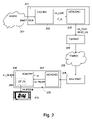
図3は、HDR及びSDR画像ペアの単なる1つの例示的な(非限定的な)色変換ベースの符号化を設計可能な手法を示しており、この例では特定の必ずしも必要ではないが有用な特性として、色度を保存する輝度再計算を有し、この例は国際公開第2014056679号から取られている。この処理は、SDR及びHDR画像の両方について1.0の最大相対輝度に正規化された色域で見た場合に理解することができる(すなわち、SDR及びHDRが同一の、たとえばRec.2020の原色を有すると仮定すると、国際公開第2014056679号の図1に示されるように、それらは全く同一のテント形状の色域を有する)。たとえば、任意のディスプレイを駆動して、カウボーイが駆動画像においてディスプレイのピーク明度の10%の輝度に対応するルマ符号を有するならば、ディスプレイのPBが高いほど、そのカウボーイは明るくレンダリングされる。これは望ましくない場合があり、その理由は、カウボーイを全てのディスプレイで(ほぼ)同じ輝度で、たとえば、60nitでレンダリングしたい場合があるためである。そのとき、当然ながら、同じ最終的なレンダリング輝度を得るためには、ディスプレイのPBが高いほど、相対輝度(又は対応する10ビットルマ符号)は低くなければならない。すなわち、(使用される符号を定義するEOTFの正確な形状に応じて)たとえばSDR画像でのルマ符号800から、HDR画像でのルマ符号100などへのダウングレードマッピングとしてその要望を表すことができ、又は輝度では、60%のSDR輝度を、4000nitのHDRディスプレイではたとえばその1/40に、若しくはそれに対応する最適にグレーディングされた画像にマッピングする。本文書におけるダウングレードとは、ピクセルのルマ符号(又はこれに対応するレンダリングすべき輝度)を、より高いピーク明度の表現(すなわち、1000nitPBなどのより高いPBディスプレイ上にレンダリングするためのもの)から、より低いPB画像における同一のシーンの画像のルマに変更して、100nitSDRディスプレイなどのより低いPBディスプレイにレンダリングすることを意味し、アップグレーディングとは、より低いPB画像をより高いPB画像に変換するための逆の色変換であり、これは、新たなピクセルを追加すること、及びいくつかのピクセル又はそれらのピクセルのいくつかの色成分を破棄することである空間的なアップスケーリング及びダウンスケーリングと混同すべきではない。これは、(RGB)トリプレットがディスプレイ又は符号化符号色域内のある色度(x,y)に対応する任意の色に対して、その色度について利用可能な(レンダリング可能な)最大輝度Lmax(x,y)に自動的にスケーリングするような手法で、図3の装置によって行うことができる。実際には、これが、無彩色軸(すなわち、特定の色相を有さない色のもの)上で、SDR画像の色の入力輝度Lを、最適なHDRグレーディング画像の必要な相対出力輝度L*にする同様の輝度マッピングを適用することに対応することを実証することができる。詳細に入り込まずに、本教示に関連することは、対応する色変換を、乗算器311による、1.0より大きい又は小さい定数gを用いた、(好ましくは線形の)RGB成分に対する成分別の乗法的変換として実現することができ、これは、選択される輝度変換関数L_out=TM(L_in)の任意の形状に対応し、これはまた、ピクセルの入力された赤色、緑色及び青色値の最大値の関数変換として定式化することができるということである。したがって、輝度マッパー307が、何らかのSDR輝度からHDR輝度へのマッピング関数、たとえば、パラメトリックに指定された対数ガンマ関数若しくはシグモイド、又はLUTとして受信された多重線形曲線を取得した場合、各入力色(R,G,B)に対して、Im_RLDRをIm_RHDRに(又は、Im3000nitなどの他の任意のグレーディング画像に適切にスケーリングされるように)変換する所望の色変換を適用するための適切なg値が計算される。例示的な実施形態の回路の構成要素は、処理中のピクセル色のR、G、及びB値の最大値(maxRGB)を出力する最大値計算器305と、システムが現在動作しているある色定義標準、たとえば、Rec.2020に従って色の輝度を計算する輝度変換器301と、L/max(R,G,B)としてLmax(x,y)を生成する除算器302と、実際にはmaxRGBへのマッパーとして動作して、m*=TM(maxRGB)を生成し、TMはF_ctの輝度変換部分を規定するある関数である、輝度マッパー307と、L*=(m*)xLmax(x,y)を生成する乗算器308と、本実施形態では実際には除算器であり、g=L*/L、すなわち、出力HDR相対輝度を入力SDR相対輝度Lで割ったものを計算するゲイン決定ユニット310と、3つの色成分R、G、Bに同一のg係数を乗算するように構成される乗算器311である。
FIG. 3 shows a technique for designing just one exemplary (non-limiting) color conversion based encoding of HDR and SDR image pairs, which is specific, but not necessarily necessary, useful in this example. As a characteristic, it has a luminance recalculation that preserves chromaticity, an example of which is taken from WO 2014056679. This process can be understood when viewed in a color gamut normalized to a maximum relative brightness of 1.0 for both SDR and HDR images (ie, SDR and HDR are identical, eg Rec. 2020). Assuming they have primary colors, they have exactly the same tent-shaped color gamut, as shown in FIG. 1 of WO 2014506679). For example, if you drive an arbitrary display and the cowboy has a Luma code corresponding to the brightness of 10% of the peak brightness of the display in the driven image, the higher the PB of the display, the brighter the cowboy will be rendered. This may not be desirable because you may want to render the cowboy at (nearly) the same brightness on all displays, for example at 60 nits. Then, of course, the higher the PB of the display, the lower the relative brightness (or the corresponding 10-bit Luma code) must be in order to obtain the same final rendering brightness. That is, the request can be expressed as a downgrade mapping (depending on the exact shape of the EOTF that defines the code used), for example, from the Luma code 800 in the SDR image to the
この回路はいくつかの色符号化に適している。しかしながら、理想的には、一般的に使用されるように、一般的なSDR符号化で動作させることを望む。HEVC復号器207から出たときのIm_LDRは、典型的には非線形Y’CbCr符号化である(ここで、ルマY’のRec.709非線形性が近似的に平方根であると仮定することができ、すなわち、輝度が一定でない問題を無視すると、近似的にY’=sqrt(L)となる)。
This circuit is suitable for some color coding. However, ideally, it is desired to operate with common SDR coding, as is commonly used. Im_LDR when exiting
図4は、同じ意図の輝度変更色処理を、Y’、Cb及びCrピクセル色成分への直接的な乗算戦略として実現する可能性を示している。また、乗算用のゲイン値gを得るために(それぞれ選択された実施形態の場合に従って、線形輝度L又は平方根入力輝度Y’によって)まだ除算を行う必要があるTM()関数を伝達する代わりに、この場合、画像内のピクセルの可能なルマY’値に対して必要な様々なg値を、たとえば、ルックアップテーブルg_ctとして、又は受信側が正しい関数変換仕様を受信する限り、より少ないデータしか必要としない任意の等価な体系化として伝達しておき、この例では、符号化されたHDRシーンの受信されたSDRルック画像からマスターHDR画像を再構成する。熟練した読者ならば、様々な態様を、様々な実施形態において入れ替えて組み合わせることができると述べる場合を理解するはずである。たとえば、HDRの現在計算すべきピクセル色についての正しい最終的な輝度、すなわちL_out_HDRによって、色の輝度非依存符号化(たとえば、色度)のスケーリングを行う他の実施形態もあり得る。 FIG. 4 shows the possibility of realizing the same intentional luminance change color processing as a direct multiplication strategy for Y', Cb and Cr pixel color components. Also, instead of transmitting a TM () function that still needs to be divided (by linear luminance L or square root input luminance Y'as in each selected embodiment) to obtain a gain value g for multiplication. , In this case, the various g values required for the possible Luma Y'values of the pixels in the image, for example as a look-up table g_ct, or as long as the receiver receives the correct function conversion specifications, less data. Communicated as any equivalent systematization that is not needed, in this example the master HDR image is reconstructed from the received SDR look image of the encoded HDR scene. Experienced readers will understand the case where it is stated that different embodiments can be interchanged and combined in different embodiments. For example, there may be other embodiments in which the brightness-independent coding (eg, chromaticity) of the color is scaled by the correct final brightness for the currently calculated pixel color of HDR, ie L_out_HDR.
また、復号器400において、(一部の実施形態、たとえば、4:4:4符号化では任意選択であるアップスケーラ401及び402の後に)色空間変換ユニット403によりYCbCrからRGBへ変換して、R’、G’及びB’値(ここでは非線形、すなわち、プライム記号’を打つことで示される線形加法性色成分の平方根)を取得し、最大値計算ユニット404によってそれら3つの色成分の最大値を計算することを見ることができる(なお、いくつかの代替的な実施形態は、Wr*R’などの重み付き版、最大化への他の入力、たとえば、ルマY’又はピクセル色の輝度Lの再構成値若しくは近似を使用するが、根本概念を十分に簡潔に保つためにこれらの詳細を説明することはない)。ゲイン決定ユニット405は、作成側から(たとえば、BDディスク上のメタデータ、又は通信されるビデオ信号として、たとえば、SEIメッセージ又は同様のメカニズムとして)、ピクセル色(すなわち、特定の画像内容)に応じた所望のゲインの仕様、すなわち、LUTとしてのg_ctなどを受信することになり、この処理中のピクセルに対するg値を出力するように構成され、これを乗算器409、410及び411が使用して、色成分に乗算し、たとえば、受信されたSDR画像の入力ルマであるY’4Lに乗算し、HDRルマであるY’4H=g*Y’4Lとなる。この例は、色差成分Cb及びCrに対して異なるゲイン係数gsを有する任意選択の可能性も示しており、その場合、決定されたg値に基づいてこれらの値を決定する任意選択のアップスケーラ407及び408が存在する。
Also, in the
また、さらなる色変換器412が、その(たとえば、復号処理コアの内部の)YCbCr色を、目的に適した他のフォーマット、たとえば、SMPTE ST.2084 EOTF又は符号割り当て関数に従って符号化されたR’’、G’’及びB’’値に変換することができ、たとえば、その理由は、正しくグレーディングされた画像が供給されるディスプレイ420が、たとえばHDMI(登録商標)接続を介して、画像カラー通信フォーマットとしてそのようなフォーマットを要求するためであるということも情報として示す。
Further, an
したがって、HDR符号化、通信、及び正しい復号を可能にするために、これらの符号化器及び復号器トポロジは全て可能である。ただしこれは、望む全てのものが得られるという意味ではない。実際に、たとえば0.01nitから1000nit(又は5000nit)までのピクセル輝度をレンダリング可能な優れたHDRディスプレイを指定することが必要である。これは、それに表示するきれいに見える画像が得られるという意味ではない。これが制作アーティストの問題になると考えるならば、まだ中間の符号化技術を有していることを認識すべきであり、単一のHDR画像符号化では、任意の適切な可逆復号可能な符号割り当てで十分であるが、HDRシーンのいくつかのダイナミックレンジルック(すなわち、少なくとも2つ、典型的にはSDR及びHDRであるが、たとえば、2つのHDRルック、たとえば、1000nitHDR版及び10,000nitHDR画像を符号化する場合に同じ原理を適用することができる)を同時に符号化可能にする符号化技術には、さらなる実際的な制限があり、これは詳細な技術的な注意を払って対処される必要があり、さもなければ符号化システムの有用性を制限することになる。より具体的には、グレーダが実現できること、特にSDR画像のルックの質とHDR画像の質との間にはトレードオフがあり、これらは理想的には(全ての実際的な制約、たとえば、人間のグレーダがルックを微調整する時間の欠如、又はいくつかの色関数をサポートしていない特定のICの複雑性の低減などが課せられた場合に)いずれも良好又は少なくとも十分な品質でなければならない。しかしながら、少なくともある者はHDR画像が良質であることを期待し、そうでなければわざわざ新たな高品質システムを作らない。具体的には、HDRはレンダリング画像のかなり高い明度部分に関するものであり得るが、画像の暗い領域についても十分な技術的注意が払われなければならず、これは以下の実施形態によって対応するさらなる実際的な問題である。 Therefore, all of these encoder and decoder topologies are possible to enable HDR coding, communication, and correct decoding. However, this does not mean that you will get everything you want. In fact, it is necessary to specify a good HDR display capable of rendering pixel luminance from, for example, 0.01 nit to 1000 nit (or 5000 nit). This does not mean that you will get a nice looking image to display on it. If you think this will be a problem for the production artist, you should be aware that you still have an intermediate coding technique, with a single HDR image coding with any suitable reversible decodable code assignment. Sufficiently, some dynamic range looks of the HDR scene (ie, at least two, typically SDR and HDR, but for example, two HDR looks, eg, 1000 nit HDR version and 10,000 nit HDR image are encoded. There are additional practical limitations to the coding technology that allows simultaneous coding (the same principle can be applied when converting), which must be addressed with detailed technical attention. Yes, or else it would limit the usefulness of the coding system. More specifically, there are trade-offs that graders can achieve, especially between the look quality of SDR images and the quality of HDR images, which are ideally (all practical constraints, eg humans, for example). (If the grader lacks time to fine-tune the look, or is subject to a reduction in the complexity of certain ICs that do not support some color functions, etc.) either is not good or at least of sufficient quality. It doesn't become. However, at least some expect the HDR image to be of good quality, otherwise they will not bother to create a new high quality system. Specifically, HDR may relate to a fairly high brightness portion of the rendered image, but sufficient technical attention must also be paid to the dark areas of the image, which is further addressed by the following embodiments. It's a practical matter.
Rocco Gorisら、「Philips response to Cfe for HDR and WCG、112、MPEG meeting 2015年6月23日/2015年7月、Warsaw no.MPEG2015/m36266には、画像のHDR及びSDRグレーディング間の構造化された変換、及びその逆、特に関数的結合符号化及びその通信を可能にするための、出願人によって開発された可能な手法の1つが記載されている。しかしながら、教示されていないのは、深いHDRの黒を安全に扱うための差異のある具体的な手法である。 Rocco Goris et al., "Philipps response to Cfe for HDR and WCG, 112, MPEG meeting June 23, 2015/July 2015, Warsaw no. MPEG2015 / m36266, is structured between HDR and SDR grading of images. One of the possible techniques developed by the applicant to enable conversion and vice versa, in particular functional coupling coding and its communication, is described, however, what is not taught is deep. This is a concrete method with differences for safely handling HDR black.
複雑なHDR符号化も提案されており、たとえば、「Paul Laugaら:Segmentation-based optimized tone mapping for HDR image and video coding、2013 Picture Coding Symposium IEEE 8DEC2013、257-260頁」があるが,これは、実際的な既に展開されたビデオ処理システム(たとえば、従来のHEVC符号化)にはうまく変換されず、その理由は、特にその教示では、特定の符号化トリックが使用されているために、復号器が特に注意を必要とするピクセルの場所を示すビットマップの通信を必要とするためである。 Complex HDR coding has also been proposed, for example, "Paul Lauga et al .: Segmentation-based optimized tone mapping for HDR image and video coding, 2013 Code Code, page 20E, page 2013 It does not translate well into practical already deployed video processing systems (eg traditional HEVC coding), because the decoder uses certain coding tricks, especially in its teachings. This is because it requires communication of a bitmap indicating the location of the pixel that requires special attention.
HDRシーン画像を通信されるSDR画像として実用的に符号化する非常に有利なシステムは、受信された100nitの標準ダイナミックレンジ画像(Im_RLDR)に輝度変換関数のセットを適用することに基づいてHDR画像(Im_RHDR)を計算するように構成されるHDRビデオ復号器(600、1100)であって、関数が、ダイナミックレンジ最適化器(603)によって標準ダイナミックレンジ画像のピクセルルマに適用されて、ダイナミックレンジが調整されたルマ(Y’HPS)が生成される粗輝度マッピング(FC)と、続いてレンジ伸長器(604)による、ダイナミックレンジが調整されたルマ(Y’HPS)の最暗値(0)の、受信された黒オフセット値(Bk_off)へのマッピングである第2の関数とを少なくとも含み、ビデオ復号器が、粗マッピング及び最暗値のマッピングへの代替計算として、HDR画像の最暗輝度の部分範囲(502)に、標準ダイナミックレンジ画像の対応する最暗ルマ(Y’_in)をマッピングする代替の輝度変換関数を標準ダイナミックレンジ画像のピクセルルマに適用するように構成されるゲイン制限器(611、1105)をさらに備える、HDRビデオ復号器(600、1100)を有することにより得られる。レンジ伸長器は、典型的には、知覚的に均一な空間における線形マッピング(又は他の色空間における対応する戦略)を用いて動作する。 A very advantageous system for practically encoding an HDR scene image as a communicated SDR image is an HDR image based on applying a set of luminance conversion functions to a received 100 nit standard dynamic range image (Im_RLDR). An HDR video decoder (600, 1100) configured to calculate (Im_RHDR), the function is applied by the dynamic range optimizer (603) to the pixel Luma of a standard dynamic range image to obtain a dynamic range. The darkest value (0) of the dynamic range adjusted Luma (Y'HPS) by the coarse luminance mapping (FC) that produces the adjusted Luma (Y'HPS) and subsequently by the range extender (604). Including at least a second function that is a mapping to the received black offset value (Bk_off), the video decoder uses the darkest brightness of the HDR image as an alternative calculation to the coarse mapping and the darkest mapping. A gain limiter configured to apply an alternative luminance conversion function that maps the corresponding darkest Luma (Y'_in) of the standard dynamic range image to the pixel Luma of the standard dynamic range image (502). Obtained by having an HDR video decoder (600, 1100) further comprising 611, 1105). Range extenders typically operate with linear mapping (or corresponding strategies in other color spaces) in a perceptually uniform space.
このゲイン制限器戦略は、グレーディング関数の選択時に多少荒い場合がある人間のカラーグレーダに、望むようにHDR画像に対応するSDRルックを取得させる(たとえば、HDR画像の一部を深いSDR黒に押し込むことによって、符号化の良好な技術特性、すなわち、HDR画像の十分な品質の再構成可能性を保証して)場合だけでなく、たとえば、2つの利用可能な作成済みのグレーディング、すなわちHDR画像及び対応するSDRルック画像、又はHDR画像特性などの分析に基づいて、HDR画像から合理的なSDR画像として自動的に計算されるSDR画像に基づいて関数形状又はパラメータを推定する自動アルゴリズムにとって特に有益である。グレーダは、自分が何をしているのかを参照ディスプレイ上で(たとえば、SDR参照ディスプレイ上で、HDRディスプレイ上のマスターHDR画像とチェックして)確認することができるが、テレビ制作中にリアルタイムで動作する自動アルゴリズムはできない。最暗HDRシーン色のゲイン制限される並列符号化(復号)は、HDR再構成の良好な品質を保証する。SDRルックの芸術的側面の需要と、対応するSDR画像として通信されるHDR入力画像の再構成の品質との両方に関して、現在、SDRルマの全範囲にわたって優れた制御があり、本システムは単純であり、風変わりなトリック、及び輝度マッピング関数を超えたさらなる符号化を必要とせずに、既に展開されたビデオ通信システムにおけるさらなる処理(たとえば、MPEG符号化/復号)に関しても、SDR画像に期待されるものに適合する。並列戦略の計算の最初の輝度マッピングが良好である場合、それが選択されることになり、その理由は、典型的には作成側の人間のグレーダなどによる所望のグレーディングを含むためであるが、そうでなければ、受信側の復号器によるHDR再構成に最低限必要とされるものよりも悪い場合、ゲイン制限戦略が選択されることになり、これはHDR再構成の観点から必要とされる最小品質レベルにとって少なくとも十分に良好となるように設計されている。 This gain limiter strategy causes a human color grader, which can be a bit rough when selecting a grading function, to get the SDR look corresponding to the HDR image as desired (eg, push a portion of the HDR image into deep SDR black). By doing so, not only when (guaranteeing good technical properties of encoding, ie, sufficient quality reconstructability of HDR images), but also, for example, two available pre-made grading, ie HDR images and Especially useful for automated algorithms that estimate functional shapes or parameters based on SDR images that are automatically calculated from HDR images as rational SDR images based on analysis of the corresponding SDR look image, or HDR image characteristics, etc. be. The grader can see what he is doing on the reference display (for example, on the SDR reference display, check with the master HDR image on the HDR display), but in real time during television production. There is no automatic algorithm that works. Gain-limited parallel coding (decoding) of the darkest HDR scene color ensures good quality of HDR reconstruction. The system is simple, with excellent control over the entire range of SDR Luma, both in terms of both the demand for the artistic side of the SDR look and the quality of the reconstruction of the HDR input image communicated as the corresponding SDR image. There are also expectations for SDR images for further processing (eg, MPEG coding / decoding) in already deployed video communication systems without the need for quirky tricks and further coding beyond the brightness mapping function. Fits things. If the initial luminance mapping in the parallel strategy calculation is good, it will be selected, because it typically includes the desired grading, such as by the creator's human grader. Otherwise, if it is worse than the minimum required for HDR reconstruction by the receiving decoder, a gain limiting strategy will be selected, which is required from the perspective of HDR reconstruction. Designed to be at least sufficiently good for the minimum quality level.
以下の変形例及び実施形態もまた有利である。 The following modifications and embodiments are also advantageous.
ゲイン制限器が、輝度変換関数のセットを適用することによって得られる中間HDR輝度(L_HDR_IM)と、入力ルマ(Y’_in)の関数との最小値を計算するように構成される、HDRビデオ復号器(600)。これは必要な戦略が単純な計算によって実現される場合に、符号化器及び復号器にとって有利である。 HDR video decoding, where the gain limiter is configured to calculate the minimum value between the intermediate HDR brightness (L_HDR_IM) obtained by applying a set of brightness conversion functions and the function of the input Luma (Y'_in). Vessel (600). This is advantageous for encoders and decoders when the required strategy is realized by simple calculations.
代替の輝度変換が、所定の又は受信された定数(1/gP)と、知覚ルマ(Y’P)の値との乗算として定義され、その知覚ルマ(Y’P)が、非線形関数を入力ルマに適用することによって計算され、その非線形関数が、互いに等距離の位置にある知覚ルマの値のセットが視覚的に均一な明度の外観を有することを特徴とする、HDRビデオ復号器(600)。知覚色空間における実施形態は、うまく機能することが分かっている。 An alternative luminance conversion is defined as the multiplication of a given or received constant (1 / gP) by the value of the perceptual Luma (Y'P), the perceptual Luma (Y'P) inputting a non-linear function. An HDR video decoder (600), calculated by applying to Luma, whose non-linear function is characterized in that a set of perceptual Luma values located equidistant from each other has a visually uniform brightness appearance. ). Embodiments in the perceptual color space have been found to work well.
非線形関数が、
Y’P=log[(1+(rho-1)*power(L_SDR_in,1/2,4)]/log(rho)
の定義を有し、L_SDR_inは標準ダイナミックレンジ画像(Im_RLDR)の線形輝度であり、rhoは所定の又は通信される定数である、HDRビデオ復号器(600)。
Non-linear function,
Y'P = log [(1+ (rho-1) * power (L_SDR_in, 1/2, 4)] / log (rho)
The HDR video decoder (600), wherein L_SDR_in is the linear luminance of a standard dynamic range image (Im_RLDR) and rho is a given or communicated constant.
定数(1/gP)が、HDRビデオ復号器によって、HDR画像の符号化ピーク明度(PB_C)の受信値の関数として決定される、HDRビデオ復号器(600)。 The HDR video decoder (600), wherein the constant (1 / gP) is determined by the HDR video decoder as a function of the received value of the coded peak brightness (PB_C) of the HDR image.
代替の輝度変換、又は標準ダイナミックレンジ画像(Im_RLDR)の少なくとも最暗輝度に対する輝度変換関数のセットに基づく変換のいずれかの選択を制御するためのプロセッサ(901)を備え、輝度変換関数のセットが、最暗HDR輝度に対する、標準ダイナミックレンジ画像(Im_RLDR)の最暗輝度への変換の仕様を含む微細グレーディング関数を含む、HDRビデオ復号器(600)。 A set of luminance conversion functions comprises a processor (901) for controlling the selection of either an alternative luminance conversion or a transformation based on a set of luminance conversion functions for at least the darkest brightness of a standard dynamic range image (Im_RLDR). An HDR video decoder (600) that includes a fine grading function that includes a specification for conversion of a standard dynamic range image (Im_RLDR) to darkest luminance for darkest HDR luminance.
そのプロセッサ(901)が、黒オフセット(Bk_off)の受信値がゼロであるか否かの確認に基づいて、適用すべき輝度変換を決定するように構成される、HDRビデオ復号器(600)。 The HDR video decoder (600) is configured such that the processor (901) determines the luminance conversion to be applied based on the confirmation of whether the received value of the black offset (Bk_off) is zero.
より多くの可能性を有する実施形態は、より複雑ではあるが、複雑なHDRシナリオ又は要求に対してさらに優れた、より調和した対処を可能にする。 The more potential embodiments allow for better and more harmonious coping with more complex but complex HDR scenarios or requirements.
入力HDR画像(Im_RHDR)の100nitの標準ダイナミックレンジ画像(Im_RLDR)表現を計算するように構成されるHDRビデオ符号化器であって、HDRビデオ符号化器は、
- 入力HDR輝度又はルマ(Y’HP)の値を最小の黒の値にマッピングするように構成されるレンジ伸長器(702)であって、最小の黒の値が典型的にはゼロである、レンジ伸長器(702)と、
- 粗輝度マッピング(FC)、たとえば、HDR画像の2つの輝度部分領域の、結果のルマ(Y’R)の範囲の2つの部分領域への割り当てを指定する関数を適用するように構成されるダイナミックレンジ最適化器(703)と、
- HDR画像の最暗輝度のサブセット(502)を標準ダイナミックレンジ画像の対応する最暗ルマ(Y’_in)に変換するための代替の輝度変換関数を適用するように構成されるゲイン制限器(707)と
を備える、HDRビデオ符号化器。
An HDR video encoder configured to compute a 100 nit standard dynamic range image (Im_RLDR) representation of an input HDR image (Im_RHDR).
-A range extender (702) configured to map the input HDR luminance or Luma (Y'HP) value to the minimum black value, where the minimum black value is typically zero. , Range extender (702),
-Coarse luminance mapping (FC), eg, configured to apply a function that specifies the allocation of two luminance subregions of an HDR image to two subregions of the resulting Luma (Y'R) range. With the dynamic range optimizer (703),
-A gain limiter configured to apply an alternative luminance conversion function to transform the darkest luminance subset (502) of an HDR image to the corresponding darkest Luma (Y'_in) of a standard dynamic range image. 707) and an HDR video encoder.
入力HDR画像(Im_RHDR)の100nitの標準ダイナミックレンジ画像(Im_RLDR)表現を計算するように構成されるHDRビデオ符号化器であって、HDRビデオ符号化器は、
- 入力HDR輝度又はルマ(Y’HP)の値を最小の黒の値にマッピングするように構成されるレンジ伸長器(702)であって、最小の黒の値が典型的にはゼロであり、出力として伸長された色表現の輝度又はルマ(Y’HPS)を生成する、レンジ伸長器(702)と、
- HDR画像の暗い及び明るい輝度部分領域の、結果のルマ(Y’R)の範囲の対応する暗い及び明るい部分領域への割り当てを指定する粗輝度マッピングを、伸長された色表現の輝度又はルマ(Y’HPS)に適用するように構成されるダイナミックレンジ最適化器(703)と、
- 入力HDR画像の輝度又はルマへの代替計算として、HDR画像の最暗輝度のサブセット(502)を標準ダイナミックレンジ画像の対応する最暗ルマ(Y’_in)の範囲に変換するための代替の輝度変換関数を適用するように構成されるゲイン制限器(707)と
を備える、HDRビデオ符号化器。
An HDR video encoder configured to compute a 100 nit standard dynamic range image (Im_RLDR) representation of an input HDR image (Im_RHDR).
-A range extender (702) configured to map the input HDR luminance or Luma (Y'HP) value to the minimum black value, where the minimum black value is typically zero. , A range extender (702) that produces the luminance or Luma (Y'HPS) of the extended color representation as an output.
-A coarse-brightness mapping that specifies the allocation of the dark and bright luminance subregions of the HDR image to the corresponding dark and bright subregions of the resulting Luma (Y'R) range, with the luminance or Luma of the extended color representation. A dynamic range optimizer (703) configured to apply to (Y'HPS), and
-As an alternative calculation to the brightness or Luma of the input HDR image, an alternative to convert the darkest luminance subset (502) of the HDR image to the corresponding darkest Luma (Y'_in) range of the standard dynamic range image. An HDR video encoder with a gain limiter (707) configured to apply a luminance conversion function.
代替の輝度変換が、所定の又は受信された定数(gP)と、知覚ルマ(Y’HP)の値との乗算として定義され、その知覚ルマ(Y’HP)が、非線形関数をHDR入力輝度(L_in)に適用することによって計算され、その非線形関数が、互いに等距離の位置にある知覚ルマの値のセットが視覚的に均一な明度の外観を有することを特徴とし、ゲイン制限器(1204)が、所定の又は受信された定数(gP)が乗算された知覚ルマと、知覚ルマ(Y’HP)に、レンジ伸長器によるレンジ伸長と、ダイナミックレンジ最適化器による粗輝度マッピングとを連続して適用した結果得られる知覚ルマ(Y’P)の値との最大値を計算する、上記のHDRビデオ符号化器。 An alternative luminance conversion is defined as the multiplication of a given or received constant (gP) by the value of the perceptual Luma (Y'HP), the perceptual Luma (Y'HP) having a non-linear function of the HDR input luminance. Calculated by applying to (L_in), its non-linear function is characterized by a set of perceptual Luma values at equidistant positions from each other having a visually uniform brightness appearance, gain limiter (1204). ) Is the perceptual Luma multiplied by a predetermined or received constant (gP), and the perceptual Luma (Y'HP) is continuously expanded by the range extender and the coarse luminance mapping by the dynamic range optimizer. The above-mentioned HDR video encoder that calculates the maximum value with the value of the perceptual Luma (Y'P) obtained as a result of the application.
受信された100nitの標準ダイナミックレンジ画像(Im_RLDR)に輝度変換関数のセットを適用することに基づいてHDR画像(Im_RHDR)を計算するように構成されるHDRビデオ復号の方法であって、関数が少なくとも粗輝度マッピング(FC)を含み、方法が、
- 粗輝度マッピング(FC)を入力輝度(L_SDR_in)又はその関数である入力ルマ(Y’P)に適用して、ダイナミックレンジが調整されたルマ(Y’HPS)を生成するステップと、
- HDR画像の最暗輝度のサブセット(502)に収まる輝度を、標準ダイナミックレンジ画像の対応する最暗ルマ(Y’_in)から計算するための、粗マッピングを含む輝度変換に代わる代替の輝度変換関数を決定し、代替の輝度変換関数により決定されたルマ(Y’PFB)と、少なくとも粗輝度マッピングを適用することによって得られるルマ(Y’HP)とのうち最も低いものを選択することによってゲイン制限戦略を適用するステップと
を有する、HDRビデオ復号の方法。
A method of HDR video decoding configured to compute an HDR image (Im_RHDR) based on applying a set of luminance conversion functions to a received 100 nit standard dynamic range image (Im_RLDR), wherein the function is at least. Including coarse brightness mapping (FC), the method,
-A step of applying coarse brightness mapping (FC) to the input brightness (L_SDR_in) or its function, the input Luma (Y'P), to generate a dynamic range adjusted Luma (Y'HPS).
-An alternative luminance conversion that replaces the luminance conversion, including coarse mapping, to calculate the luminance that fits within the darkest luminance subset (502) of the HDR image from the corresponding darkest Luma (Y'_in) of the standard dynamic range image. By determining the function and selecting the lowest of the Luma (Y'PFB) determined by the alternative luminance conversion function and at least the Luma (Y'HP) obtained by applying the coarse luminance mapping. A method of HDR video decoding with a step of applying a gain limiting strategy.
代替の輝度変換関数を決定するステップが、知覚的に均一な空間で定義される標準ダイナミックレンジ画像の少なくとも最暗入力ルマ(Y’_in)に対する線形関数であって、所定の又は受信された定数(1/gP)に、それぞれの入力ルマ(Y’_in)に対応する知覚ルマ(Y’P)の値を乗算することによって計算される線形関数を決定するステップを有する、請求項10に記載のHDRビデオ復号の方法。
The step in determining the alternative luminance conversion function is a linear function for at least the darkest input Luma (Y'_in) of a standard dynamic range image defined in a perceptually uniform space, a given or received constant. 10. The aspect of
入力HDR画像(Im_RHDR)の100nitの標準ダイナミックレンジ画像(Im_RLDR)表現を計算するためのHDRビデオ符号化の方法であって、
- 入力HDR輝度又はルマ(Y’HP)の値を、マッピングの出力であるレンジ調整されたルマ(Y’HPS)の最小の黒の値にマッピングするマッピングを適用するステップであって、最小の黒の値が典型的にはゼロである、適用するステップと、
- HDR画像の最明及び最暗輝度の輝度部分範囲の、結果のルマ(Y’R)の範囲のそれぞれの対応する最明及び最暗部分範囲への割り当てを指定する粗輝度マッピング(FC)を、レンジ調整されたルマ(Y’HPS)に続いて適用するステップと、
- マッピング及び粗輝度マッピングの組み合わせへの代替の輝度変換として、HDR画像の最暗輝度の部分範囲(502)を、標準ダイナミックレンジ画像の対応する最暗ルマ(Y’_in)に変換するための代替の輝度変換関数を適用するように構成されるゲイン制限戦略を適用するステップと
を有する、HDRビデオ符号化の方法。
A method of HDR video coding for computing a 100 nit standard dynamic range image (Im_RLDR) representation of an input HDR image (Im_RHDR).
-The step of applying a mapping that maps the input HDR luminance or Luma (Y'HP) value to the minimum black value of the range adjusted Luma (Y'HPS), which is the output of the mapping, and is the minimum. The step to apply and the step where the black value is typically zero,
-Rough luminance mapping (FC) that specifies the assignment of the brightest and darkest luminance subranges of an HDR image to the corresponding brightest and darkest luminance subranges of the resulting Luma (Y'R) range, respectively. With the steps to apply, following the range-adjusted Luma (Y'HPS),
-As an alternative luminance conversion to a combination of mapping and coarse luminance mapping, to convert the darkest partial range (502) of an HDR image to the corresponding darkest Luma (Y'_in) of a standard dynamic range image. A method of HDR video coding with a step of applying a gain limiting strategy configured to apply an alternative luminance conversion function.
ゲイン制限が、入力HDR画像(Im_RHDR)の輝度(L_in)に知覚化関数を適用して得られる知覚的に均一化されたルマ(Y’HP)に係数(gP)を乗算することによって、代替の輝度変換関数を計算する、請求項12に記載のHDRビデオ符号化の方法。 Gain limiting is substituted by multiplying the perceptually homogenized Luma (Y'HP) obtained by applying a perceptualization function to the luminance (L_in) of the input HDR image (Im_RHDR) by a factor (gP). 12. The method of HDR video coding according to claim 12, wherein the luminance conversion function of the above is calculated.
新たな本技術的思想は様々な形態で具現化され、たとえば、接続されたシステム、汎用又は専用ネットワークを介して通信される遠隔地の部分的サービス、プロセッサ上で動作する場合に、プロセッサが上記の方法クレームの1つの全ての方法のステップを実行することを可能にするコードを含むコンピュータプログラム製品、符号化器/送信器と復号器/受信器との間で協調して通信される必要がある様々な必要なメタデータを含む任意のビデオ信号の体系化などがある。 The new technical idea is embodied in various forms, for example, when the processor operates on a connected system, a remote partial service communicated over a general purpose or dedicated network, or a processor. A computer program product that contains code that allows you to perform all the steps of one method of claim, which needs to be coordinated and communicated between the encoder / transmitter and the decoder / receiver. There is the systematization of any video signal that contains some necessary metadata.
本発明による方法及び装置のこれら及び他の態様は、以下に説明される実装形態及び実施形態を参照して、また、添付の図面を参照して明らかになり解明され、図面はより一般的な概念を例示する非限定的な特定の例示としての役割を果たすにすぎず、構成要素が任意選択であることを示すために破線が使用され、非破線の構成要素は必ずしも必須ではない。また、破線は、必須であると説明されている要素が物体の内部に隠れていることを示すために、又は物体/領域の選択(及びディスプレイに表示される態様)などの無形のもののために使用することもできる。 These and other aspects of the methods and devices according to the invention will be clarified and elucidated with reference to the embodiments and embodiments described below and with reference to the accompanying drawings, the drawings being more general. Dashed lines are used to indicate that the components are optional, and the non-dashed components are not always required, as they serve only as a non-limiting specific example to illustrate the concept. Also, dashed lines are used to indicate that the elements described as essential are hidden inside the object, or for intangible objects such as object / region selection (and aspects shown on the display). It can also be used.
図5は、曲線、輝度(又はルマ)マッピング曲線を用いてSDR画像及びHDR画像の間の変換をモデル化することができる手法の例を示す。すなわち、SDR画像を受け取った場合にも、逆曲線を適用することによって、作成側のマスターHDR画像をほぼ再構成することができる。いくつかの実施形態では、セカンダリ再グレーディング画像(すなわち、本説明では、明確にするためのほんの一例として、PB_C=1000nitのHDR画像)内のピクセルの領域(たとえば、物体に対応)を、プライマリ画像、すなわち、SDRのPB_C=100nit画像内の幾何学的に対応するピクセルに基づいて計算するのに関与する様々な色変換が存在する。たとえば、局所的な色変換が、一部の領域にのみ適用され、画像の残りの部分には適用されない。しかしながら、実際的な理由から、多くのシナリオでは、安価である必要がある特定の実施形態のシステムにおけるICの複雑性、又は人間のグレーディングの関与に使用可能な時間などの理由で、単純な変換(通常は大域的なもの、すなわち、ピクセルルマに依存し、画像内の幾何学的位置又は他のそのような色関連でない特性に依存しないもの)を望む。典型的には、図5に示されたように、凸形状(図示のように、入力x軸上の1から1000nitまでこの曲線の大部分が「小文字のr型」である)から始めることを望み、あるコンテンツでは、これは既に十分にモデル化されている。可逆輝度マッピング関数のみの選択が可能な場合、量子化及びDCT誤差がなければ、HDR画像の再構成はほぼ完璧である。(元のマスターHDR画像の最適な再構成に役立ち得るように形成された)受信器に送るSDR画像の品質は、意図した(芸術的な)SDRルック画像から多少ずれている場合があるが、いくつかの用途ではそれで十分な場合がある(たとえば、ニュース番組では、ニュースリーダの顔などのように、主要な画像物体が十分な品質である限り、ニュースリーダの背後の壁にある全ての影が全てのピクセルにおいて厳密に正しいグレー値を有することは重要ではなく、言い換えれば、芸術的及び対応する技術的精度の要求が緩和される)。説明のため、2つの前もって存在するグレーディング、すなわち、PB_C=1000nitのマスターHDRグレーディング画像と、それに対応する最適に見えるSDR画像とに基づいて、通信されるSDR代表画像を自動的に符号化するものとする。すなわち、人間ではなく画像解析アルゴリズムが、HDRからSDRへの輝度変換(又はその逆)の関数形状を決定する。芸術的に最適に見えることの意味は、マスターHDR画像よりもここでは10倍小さい輝度ダイナミックレンジ(0~PB_C_HDR=1000nitではなく、0~PB_C_SDR=100nit)内で、全ての画像物体に適切な輝度が与えられているので、HDRマスタールックを近似したルックとして、全ての物体が依然として適度に明るく見え、領域間及び物体内のコントラストが適切に見えるということである。PB_C_SDR=100nitに再スケーリングされたHDR相対輝度を再使用することなどに対応する線形圧縮関数を単に使用するとすれば、画像のより暗い領域は不快に暗くなる。この最適な輝度マッピングは、一般に、シーンのタイプと、その様々なダイナミックレンジルック画像と(たとえば、PB_C_MDR=500nitのMDR画像も)に依存し、その理由は、たとえば、画像内のどこかのガラスに彫刻された白い商標の可読性が、その映画の商業スポンサー及びそのロゴの所有者に義務を履行するために、全てのDRルックで良い品質で表現されるべき物体であるためである。したがって、あまり重要ではなくより自動的な実施形態に関して、一般性を失うことなくここで仮定するのは、人間のカラーグレーダが十分な時間を取って、マスターHDR及び導出された(最適に見える対応する)SDR画像を正確にグレーディングするということである。 FIG. 5 shows an example of a technique that can model a transformation between an SDR image and an HDR image using a curve, luminance (or Luma) mapping curve. That is, even when the SDR image is received, the master HDR image on the creating side can be substantially reconstructed by applying the inverse curve. In some embodiments, a region of pixels (eg, corresponding to an object) within a secondary regrading image (ie, in this description, an HDR image with PB_C = 1000 nits as just one example for clarity), is the primary image. That is, there are various color transformations involved in the calculation based on the geometrically corresponding pixels in the PB_C = 100nit image of the SDR. For example, local color transformations apply only to some areas, not to the rest of the image. However, for practical reasons, in many scenarios simple conversions, such as the complexity of the IC in a system of a particular embodiment that needs to be inexpensive, or the time available for human grading involvement. (Usually global, that is, one that depends on pixel luma and not on geometric positions in the image or other such non-color related properties). Typically, as shown in FIG. 5, it is recommended to start with a convex shape (as shown, from 1 to 1000 nits on the input x-axis, most of this curve is "lowercase r"). Hopefully, for some content, this is already well modeled. If only the reversible luminance mapping function can be selected, the HDR image reconstruction is almost perfect without quantization and DCT errors. The quality of the SDR image sent to the receiver (formed to help optimal reconstruction of the original master HDR image) may deviate slightly from the intended (artistic) SDR look image, although That may be sufficient for some applications (for example, in a news program, all shadows on the wall behind the news reader, as long as the main image object is of sufficient quality, such as the face of the news reader. It is not important that has exactly the correct gray value in every pixel, in other words the requirement for artistic and corresponding technical accuracy is relaxed). For illustration purposes, it automatically encodes the SDR representative image to be communicated based on two pre-existing grading, i.e., a master HDR grading image with PB_C = 1000 nits and a corresponding optimally visible SDR image. And. That is, the image analysis algorithm, not the human, determines the functional shape of the luminance conversion from HDR to SDR (or vice versa). The meaning of being artistically optimal is that the brightness is appropriate for all image objects within the brightness dynamic range (0 to PB_C_SDR = 100 nit instead of 0 to PB_C_HDR = 1000 nit), which is 10 times smaller here than the master HDR image. Is given, as a look that approximates the HDR master look, all objects still look reasonably bright, and the contrast between regions and within the object looks good. If we simply use a linear compression function that corresponds to reusing HDR relative brightness rescaled to PB_C_SDR = 100 nits, the darker areas of the image will be unpleasantly dark. This optimal luminance mapping generally depends on the type of scene and its various dynamic range look images (eg also MDR images with PB_C_MDR = 500 nits), for example because of a glass somewhere in the image. This is because the readability of the white trademark engraved on is an object that should be represented in good quality in all DR looks in order to fulfill its obligations to the commercial sponsors of the film and the owners of its logo. Therefore, for less important and more automatic embodiments, the assumption here, without loss of generality, is that the human color grader has taken enough time to master HDR and derive (optimally looking correspondence). This is to accurately grade the SDR image.
ここで、そのグレーディング画像のペアの符号化を次に、自動的に又は多少のグレーダの関与を伴って行うことができる。物事を単純にするために、自動符号化システムの例のみを説明するが、それもまた本発明の限定とみなされるべきでなく、その理由は、HDR/SDRペアの色変換ベースの符号化(すなわち、グレーディング画像のうちの一方のみが、ピクセル色のマトリックスとして、メタデータ内の他方のグレーディング画像を再計算するための関数と共に実際に通信されるもの)のために、人間のグレーダがSDR画像の作成に関与する場合、限られたベース関数の組から順次選択する場合に、同様の技術原理が適用されるためである(すなわち、特に図7の処理チェーンで説明されるように、まず1つの単純な「r型」の関数を用いて粗いSDRグレーディングを作り、次いで、必要性がまだあれば、映画を加工するための時間及び予算も考慮して、必要な変換をさらに微調整する)。一般性を失うことなく、(下記参照の、このHDR処理のために出願人によって開発された知覚明度空間変換によって決定される一種の「対数」ドメインにおけるSDR対HDR画像のヒストグラムの比較に基づく)自動輝度変換関数の決定が以下のタイプのものである例を用いて本原理を説明する。 Here, the coding of the pair of graded images can then be done automatically or with some grader involvement. To keep things simple, only an example of an automatic coding system will be described, which should also not be considered a limitation of the invention, because of the color conversion based coding of HDR / SDR pairs ( That is, because only one of the grading images is actually communicated as a matrix of pixel colors with a function to recalculate the other grading image in the metadata), the human grader is an SDR image. This is because similar technical principles apply when involved in the creation of a limited set of base functions (ie, especially as described in the processing chain of FIG. 7). Create a coarse SDR grading using two simple "r-type" functions, and then further fine-tune the required conversions, if still needed, taking into account the time and budget to process the film). .. Without losing generality (based on a comparison of histograms of SDR vs. HDR images in a kind of "logarithmic" domain determined by the perceptual brightness spatial transformation developed by the applicant for this HDR processing, see below). This principle will be described using an example in which the determination of the automatic luminance conversion function is of the following type.
これは、擬似対数知覚空間プロットにおけるデータへの適合によっても示されるように、非常に有用であることが分かっており(図5のx軸及びy軸のスケールを参照されたいが、読者はこれらを、等距離の場合に知覚的にほぼ同一の差に見える位置を与えるものとみなし、すなわち、グレー1、グレー2=20%明るいグレー、グレー3=グレー2より20%明るいグレー、などである)、これは、グレーダ又は自動最適マッチング曲線計算ユニットが、少なくともマスターHDR画像に対応するSDR画像の初期決定のために3部分曲線を入力として使用した場合のものであり、この曲線は、画像内の明るい又はハイライトピクセルについての直線傾斜部分(領域505)の角度a_Hと、より暗い色(領域503)についてのマッピングの線形近似のための(少なくともマスターHDR画像に基づくSDR再グレーディング画像の粗い決定のための)角度a_dとによって定義される。この曲線は3つの非常に有用かつ画像について多くを伝達するパラメータしか必要とせず、その理由は、曲線の第3の部分として、2つの線分が交差する点の両側に幅WPにわたって等しく伸長された曲線セグメントを使用するためである(すなわち、a_d、a_H、及びWPのみが受信器に伝達される必要があり、これは、あまりにも多くのメタデータ通信を行う余裕がないシステムにとって、又は少なくともいくつかの連続した画像のショットのグレーディングにあまりに多くの時間を費やす余裕がないグレーダにとって重要である)。使用する両端の2つの直線部分を接続する曲線部分の固定形状曲線は、典型的には、放物線セグメント(領域504)である。 This has proved to be very useful, as also shown by the fit to the data in the pseudologous perceptual space plot (see the x-axis and y-axis scales in FIG. 5, which the reader has read. Is considered to give positions that appear to be perceptually almost the same difference at equal distances, that is, gray 1, gray 2 = 20% lighter gray, gray 3 = 20% lighter than gray 2, and so on. ), This is the case when the grader or the automatic optimal matching curve calculation unit uses a three-part curve as input for the initial determination of the SDR image corresponding to at least the master HDR image, which curve is in the image. Rough determination of the SDR regrading image (at least based on the master HDR image) for a linear approximation of the angle a_H of the linearly inclined portion (region 505) for the bright or highlight pixels of and the mapping for the darker color (region 503). Defined by the angle a_d (for). This curve requires only three very useful parameters that convey much about the image, because as the third part of the curve, it is equally extended over the width WP on both sides of the point where the two line segments intersect. This is to use curved segments (ie, only a_d, a_H, and WP need to be transmitted to the receiver, which is for systems that cannot afford too much metadata communication, or at least. Important for graders who can't afford to spend too much time grading shots of several consecutive images). The fixed shape curve of the curved portion connecting the two straight portions at both ends to be used is typically a parabolic segment (region 504).
ここで、SDRグレーディング画像を決定する興味深い特性があり、これは実験的に検証することができる。多くのHDRシーンのSDRルック画像は、十分な量の暗いピクセル、すなわち、SDR黒が存在しない場合、定性的にあまりよく見えない(Rec.709曲線では、最も低い符号、たとえば10ビットルマ符号化での0、1及び2は、およそピーク明度の1/1000、すなわち100nitの1/1000の、ディスプレイにレンダリングされる輝度に対応し、これはHDRシーンの画像物体又は領域の一部に対応する)。したがって、図5の矢印によって示されるように、約0.1nitまで関数(本例では、3部分曲線の暗い物体のピクセルに対する直線部分であるが、他の関数を用いてSDRグレーディング画像を決定する実施形態でも同様である)を継続する必要があると予想するであろう(それらの物体に対してより高いSDR輝度を有する、不適切に見えるグレーディングとは対照的である)。これは、それらのHDRシーンの美しいSDR画像バージョンを与える。しかしながら、HDRシーンは当然ながら、潜在的に非常に大きなダイナミックレンジのピクセル輝度(濃い黒)を含むという特性を有する。読者は、符号が対象としている典型的な参照ディスプレイのピーク明度、又は実際にはPB_Cと比較した相対輝度について話していることに注意する必要がある(実際には、これに関係して、任意の見栄えの良いダイナミックレンジグレーディングでは、輝度の絶対的な符号化を用いて動作することが好ましいが、それらの輝度はある典型的な表示能力に差し向けられ、たとえば、薄暗い夜のリビングルームで見た1000nitディスプレイであって、元のシーンではなく、簡単な言葉で言えば、太陽が実際の10億nitの値ではなく、1000nitに符号化されレンダリングされる)。したがって、たとえば夜のシーンの典型的なHDRシーンは、現実世界では、たとえば、1nitをはるかに下回る(たとえば、0.01nit、又はさらに低い)暗い隅の輝度を有する一方で、同時に街灯は、10,000nit以上の輝度、すなわち、1,000,000:1以上のダイナミックレンジで画像内に存在し、これはそのままではSDR表現においてレンダリングも表示もできない。なお、最適な(マスター)HDR及びSDRグレーディングでは、コントラストが多少低くなることがあり、その理由は、アーティストのグレーダがシーンの最暗部分を多少明るくし、最明ピクセルを暗くしている場合があるためであるが、依然として良好な表現(符号化自体、全ての用途で)と、たとえば、0.05nitから5000nitまでの間のその例示的HDRシーンのレンダリング(たとえば、そのようなディスプレイが利用可能である場合は随時)とを所望する場合があり、すなわち、100,000:1のディスプレイにレンダリングされる所望のDRであり、これは明らかにSDR能力を上回っているので、HDR技術をそもそも元より導入している。 Here, there is an interesting property that determines the SDR grading image, which can be verified experimentally. The SDR look image of many HDR scenes does not look very good qualitatively in the absence of a sufficient amount of dark pixels, ie SDR black (on the Rec.709 curve, with the lowest code, eg 10-bit Luma coding). 0, 1 and 2 correspond to the brightness rendered on the display, approximately 1/1000 of the peak brightness, i.e. 1/1000 of 100 nit, which corresponds to a portion of the image object or region of the HDR scene). .. Therefore, as indicated by the arrows in FIG. 5, a function up to about 0.1 nit (in this example, a straight line portion of a three-part curve for a pixel of a dark object, but other functions are used to determine the SDR grading image. You would expect to continue (as well as in embodiments) (as opposed to grading that looks inappropriate, with higher SDR brightness for those objects). This gives a beautiful SDR image version of those HDR scenes. However, HDR scenes, of course, have the property of including potentially very large dynamic range pixel luminance (dark black). It should be noted that the reader is talking about the peak brightness of the typical reference display that the sign is intended for, or in fact the relative brightness compared to PB_C (in fact, in this regard, optional). For good-looking dynamic range grading, it is preferable to operate with absolute coding of brightness, but those brightness are directed to some typical display capability, for example, in a dimly lit night living room. It's a 1000 nit display, not the original scene, and in simple terms, the sun is encoded and rendered at 1000 nits, not the actual value of 1 billion nits). Thus, for example, a typical HDR scene in a night scene has, in the real world, for example, dark corner brightness well below 1 nit (eg 0.01 nit, or even lower), while at the same time the street light has 10 It exists in the image with a brightness of 000 nits or more, that is, a dynamic range of 1,000,000: 1 or more, which cannot be rendered or displayed in the SDR representation as it is. Note that with optimal (master) HDR and SDR grading, the contrast may be slightly lower, because the artist's grader may slightly brighten the darkest part of the scene and darken the brightest pixels. Because of this, there are still good representations (encoding itself, for all uses) and rendering of its exemplary HDR scenes, eg, between 0.05 nits and 5000 nits (eg, such displays are available). At any time), that is, the desired DR rendered on a 100,000: 1 display, which clearly exceeds the SDR capability, so it is based on HDR technology in the first place. More introduced.
したがって、HDR輝度点501より下のいかなるものもSDRグレーディングでレンダリングすることができない(又はRec.709ベースの技術で符号化することさえできない)場合、これは、そのSDR表現における領域502の全てのHDR値が、同じ黒(たとえば、8、10、又は12ビット表現のいずれでも、ルマ符号0)にクリップされることを意味する。これは、単にHDR画像を受信器に通信するシステム(すなわち、受信側で関数を使用して、受信したHDRピクセル化画像からSDRグレーディングを計算するだけのもの)、すなわち、その完璧に符号化された画像データを1000nitのHDRディスプレイ上に直接レンダリングすることができるシステムであって(たとえば、SMPTE 2084 OETFを使用して符号化された場合)、ディスプレイピーク明度PB_Dが1000nit未満のディスプレイを有する視聴者にとって最適なグレーディングを導出するための色変換関数しか必要としないシステムでは実際には問題にならない。たとえば、これらのクリッピング関数を使用して、受信されたHDR画像からダウングレードすることによって、SDRグレーディングを作ることができ、これは実際に正しい最適なSDRルックを生成する。
Therefore, if anything below the
しかしながら、HDRシーンの2つの異なるダイナミックレンジルック(すなわち、2つの異なるグレーディング)を符号化するシステム、たとえば、SDR画像を通信して、視聴者の大きな設置基盤に、輝度処理なしで直接レンダリングされた場合に、SDR画像を良い品質で見られるようにする必要があるシステムであって、そこから非常に良質のHDR画像再構成を、HDRディスプレイを購入した顧客のために導出するシステムは、より多くの制約を有する。通信されるSDR画像においてより暗いHDR色の一部をクリップすると、受信側で必要なHDRピクセル色を可逆的に再構成することができない。 However, a system that encodes two different dynamic range looks (ie, two different grading) of an HDR scene, eg, an SDR image, was communicated and rendered directly onto the viewer's large installation base without luminance processing. In some cases, there are more systems that need to be able to see SDR images in good quality, from which very good HDR image reconstructions are derived for customers who have purchased HDR displays. Has the limitation of. Clipping a portion of the darker HDR color in the communicated SDR image makes it impossible to reversibly reconstruct the HDR pixel color required by the receiver.
解決策は、SDR対HDR画像における対応する輝度の点の軌跡(r型の極太の点群)に接近し近似するように、黒用の線形セグメントを選択する方がより賢明であると考えるかもしれないが、その場合SDRルックの品質は著しく劣化する。たとえば、(0,0)から始まる黒用の線形セグメントによってその点群に近づくと、より暗い領域の多くが明るくなりすぎ、もはや良好なコントラストには見えなくなる(明るい背景に対してシルエットであるべき人々が、たとえば、より明るいダークグレーのシルエットになる)。これが通常のLDRシーン(すなわち、慎重に均一化された照明の下で1%と95%との間の物体反射率を有するスタジオセット)に対してより低い品質を与える場合、特にHDRシーンでは、そのシーンのSDR変形においても、十分に印象的な領域間コントラストを見ることを望む。HDRシーンのSDR表現は非常に重要で複雑な場合があり、その理由は、同時に、洞窟の暗い領域が、たとえば、洞窟の入口付近の平均的な照明の領域よりもかなり暗いことを伝えることを望む場合があるが、単純にこれらの暗い領域を非常に暗くするのではなく、たとえば、そこに立っている人物をまだ多少良好に見たい場合もあるためである。困ったことに、その問題はしばしば、より明るい領域まで及ぶことさえあり(その理由は、3部分曲線などの粗再グレーディング輝度変換曲線は、単純であるがゆえ、任意のパラメータのずれを広い輝度部分範囲にわたって拡大させるためである)、これは、たとえばほこりで散乱する光線など、慎重に制御すべきであって、シーンのルックのためにディレクターによって慎重に選択されている、SDR画像内のいくつかの局所的なコントラストに深刻な影響を与え、輝度マッピング曲線のより低い部分が良好なHDR輝度クリッピング点501に向かって曲がる戦略ではなく、むしろ絶対的なゼロ点HDR輝度=0を使用した場合に得られる白飛びした(washed-out)ルックではほとんど消えてしまう。
The solution may be to think that it is wise to choose a linear segment for black so that it approaches and approximates the locus of corresponding luminance points in the SDR vs. HDR image (r-shaped extra-thick point cloud). However, in that case the quality of the SDR look is significantly degraded. For example, as you approach the point cloud with a linear black segment starting at (0,0), many of the darker areas become too bright and no longer look good contrast (should be a silhouette against a bright background). People, for example, have a lighter dark gray silhouette). If this gives lower quality to normal LDR scenes (ie studio sets with object reflectance between 1% and 95% under carefully uniformed lighting), especially in HDR scenes. It is hoped that even in the SDR deformation of the scene, a sufficiently impressive inter-regional contrast will be seen. The SDR representation of an HDR scene can be very important and complex, because at the same time it conveys that the dark areas of the cave are significantly darker than, for example, the average illuminated area near the entrance to the cave. Sometimes you want, but you don't just want to make these dark areas very dark, for example, you may still want to see the person standing there a little better. The trouble is that the problem often extends even to brighter areas (because coarse regrading luminance conversion curves, such as tripartite curves, are simple, so any parameter shifts wide luminance. (To magnify over a partial range), this is how many in the SDR image that should be carefully controlled, for example dust-scattered rays, and carefully selected by the director for the look of the scene. If the absolute zero point HDR brightness = 0 is used rather than a strategy that seriously affects the local contrast and the lower part of the brightness mapping curve bends towards the good HDR
したがって、この問題のためには、(グレーディング又は少なくとも符号化において)追加の構成要素、特に全ての実際的なシナリオでこれに簡単に対処できるものが必要である(様々な用途に対して異なる種ではなく、単一のシステムが、場合によっては何らかの微調整された構成の後に、ハリウッドなどの映画のための高品質のオフライングレーディングから、あまり多くの変更が要求されない、たとえば、現在存在し、人々が専門としているテレビ制作過程を超えたあまりにも多くの追加の人間の専門家の関与などが要求されない、非常に安価なオンザフライのテレビ放送までの様々な用途の需要に対処することができる場合に、本当に優れたHDR符号化及び処理技術のみを有し、いずれにしても、マスターHDRグレーディング及び対応するSDRグレーディングの両方の作成、通信及び使用をマスターすれば、全ての場合において本当に優れたHDR処理システムのみを有する)。 Therefore, this problem requires additional components (in grading or at least coding) that can be easily addressed in all practical scenarios (different species for different uses). Rather, a single system, possibly after some tweaked configuration, does not require much change from high-quality offline grading for movies such as Hollywood, for example, currently exists and people When it is possible to meet the demand for a variety of applications, from very inexpensive on-the-fly television broadcasts, without the need for the involvement of too many additional human experts beyond the television production process that it specializes in. With only really good HDR coding and processing techniques, in any case, if you master the creation, communication and use of both master HDR grading and the corresponding SDR grading, you will have really good HDR processing in all cases. Has only the system).
図6は、最暗HDR色の正しい対処を有する(出願人の発明者により最近発明された概念に基づいており、さらにその上に構築する)復号器のコア輝度変換部分を示しており、これを前の図で説明された復号器の実施形態の様々な実施形態に組み込むことができる。 FIG. 6 shows a core luminance conversion portion of a decoder that has the correct treatment of the darkest HDR color (based on and built on a concept recently invented by the inventor of the applicant). Can be incorporated into various embodiments of the decoder embodiments described in the previous figure.
入力は古典的なRec.709のルマY’_in(すなわち、たとえば、0~1023の値)である。知覚空間変換ユニット601は、(図5で既に導入されたように)それらの輝度を知覚空間内に変換する。RGB色空間、たとえばRec.2020、又はY’CbCr変形などのその派生物を有する場合、表現可能な全ての色の色域は、1.0に正規化され得る尖った先端を有する三角テントであることに留意することが読者にとって有益であり、その場合、色変換は、そのテント内の色点の位置の変更とみなすことができる(HDR相対輝度又はルマは、対応するSDR輝度又はルマとは異なる高さになる)。
The input is the classic Rec. 709 Luma Y'_in (ie, for example, a value between 0 and 1023). The perceptual
たとえば、知覚表現への変更も、様々な色の高さ(すなわち、様々な単位で表される「明度」)を変更し、その理由は、たとえば、輝度軸(白を通るテントの垂直支柱)のメトリックを対数になるように再定義することが、たとえば90%の相対輝度を有する色の高さが、その位置が対数軸上に降りるあらゆる位置に変化すべきであることを意味するためである。 For example, changes to perceptual representation also change the height of different colors (ie, the "brightness" expressed in different units), for example because of the luminance axis (vertical stanchions of the tent through white). To redefine the metric to be logarithmic, for example, because the height of a color with 90% relative brightness should change to any position where its position descends on the logarithmic axis. be.
HDRシーン画像のSDR再グレーディングに対処するために様々な利点があるので、対数表現に変更する。まず、より知覚的な態様での輝度のこの均一化は、HDR画像の多少合理的で非常に粗いより低いダイナミックレンジ表現を既に得ていることを意味する。しかしながら、たとえば、夜の暗闇が正しい様式を有する必要があるシーンに芸術的に注意を払う場合、その対数画像を使用してLDRディスプレイ上に直接レンダリングすると、夜のシーンが明るすぎて不適切に見えることがあり、特定の表示ピーク明度PB_Dを有する任意のHDRディスプレイ上でどのように見えるかを述べることは簡単ではないが、少なくとも重要なHDRシーンでは、単純過ぎる対処がどのディスプレイでも最適に見えないことが予想される。正規化された色域及びその輝度軸では、HDR画像は典型的には最大値(1.0)に近い明るい物体を有し、ピクセル輝度の残りはこれをはるかに下回る。この大きなダイナミックレンジをSDR輝度範囲に絞るためには、これら2つの輝度は共に近づく必要があり、その理由は、ランプが平均ピクセル輝度512=18%より、たとえば、2倍明るいだけであり得る(たとえば、HDRでの10,000:500=20xではない)ためである。これは、近似的に対数である関数、又はそれに形状が似た何らかのより優れた関数(実際には「何らかの」ブースティングを行うもの)によって既に近似的に実現され得る。 Since there are various advantages to deal with SDR regrading of HDR scene images, change to logarithmic representation. First, this homogenization of luminance in a more perceptual manner means that we have already obtained a somewhat rational and very coarse lower dynamic range representation of the HDR image. However, for example, if you want to artistically pay attention to a scene where the darkness of the night needs to have the correct style, using that logarithmic image to render directly onto the LDR display will make the night scene too bright and inappropriate. It may be visible and it is not easy to describe what it looks like on any HDR display with a particular display peak brightness PB_D, but at least in important HDR scenes, overly simple coping looks best on any display. It is expected that there will be none. In the normalized color gamut and its luminance axis, HDR images typically have bright objects close to the maximum value (1.0), with the rest of the pixel luminance well below this. In order to narrow this large dynamic range to the SDR luminance range, these two luminances need to be close together, because the lamp may only be twice as bright as the average pixel luminance of 512 = 18% (for example). For example, it is not 10,000: 500 = 20x in HDR). This can already be achieved approximately by a function that is approximately logarithmic, or some better function that is similar in shape to it (actually one that does "some" boosting).
しかしながら、これらのSDRグレーディングは、HDR画像の良質なSDRグレーディングとして機能するにはまだあまり適しているわけではなく、その理由は、それらが非常に鈍く、コントラストが低く、しばしば白飛びしているように見えるためである。優れたグレーディングのためには、シーン内の最明ピクセルの決定可能な範囲と、最暗輝度の部分範囲との少なくとも一方、典型的には両方に行われなければならないことに十分に配慮しなければならない。そして、最も単純なバージョンでさえ、中間の範囲で行われることを中間に多少委ねることができ、たとえば、単に滑らかな接続動作を使用することができ、又は、システムがより正確な制御をそこで行うことができる(それがなければ、本コーデックトポロジでは、典型的には微細グレーディング関数を有する)。 However, these SDR gradings are not yet very suitable for functioning as good SDR grading for HDR images, because they appear to be very dull, low contrast and often overexposed. Because it looks like. Careful consideration must be given to that for good grading, it must be done in at least one, typically both, a decidable range of brightest pixels in the scene and a partial range of darkest brightness. Must be. And even the simplest version can somewhat delegate what is done in the middle range to the middle, for example, simply use a smooth connection behavior, or the system gives more precise control there. It can (without it, this codec topology typically has a fine grading function).
フィリップスは、線形輝度から知覚ルマY’Pへの変換を行う関数を発明した。 Phillips invented a function to convert linear luminance to perceptual Luma Y'P.
Y’P=log[(1+(rho-1)*power(L,1/2,4)]/log(rho) [式1]
ここで、Lは正規化された輝度であり、rhoはHDR画像のPB_Cに依存する定数であって、10,000nitでは典型的には33である。逆関数は線形化関数として、すなわち知覚的に均一なルマドメインから線形ドメインへ、すなわち輝度のドメインへ変換するための関数として使用することができる。したがって、実施形態は、輝度よりも知覚的に等間隔に広がるルマ符号を生成する知覚空間変換ユニットにおける任意の輝度知覚均一化曲線と、特に入力画像がHDR画像であることを知っている場合は、等距離の明度値によって表現される必要があるかなりのダイナミックレンジとで動作することができ(これを本出願では技術的にはルマと呼ぶ場合があり、SDR符号化時代には、輝度を符号化するために単一の手法しかなかったので、ルマがRec.709OETFによって計算されており、これは近似的には平方根であるが、HDRではルマ符号を任意の適用されたHDR OETFによって定義することができ、これは黒付近で平方根よりも急峻な関数、たとえば、SMPTE 2084 PQ関数である)、しかしながら、説明を簡単にするために、上記のフィリップスの関数であるものとする(これは式(1)のrhoでパラメータ化された対数ガンマ関数であり、ここでrhoは固定又は可変にとることができ、符号化器及び復号器が全ての通信されるビデオコンテンツに対して固定の事前に合意された最大値PB_C、たとえば、1000nitで動作する場合は、典型的には固定であり、異なるPB_Cを用いた符号化が使用される場合は可変である)。
Y'P = log [(1+ (rho-1) * power (L, 1/2, 4)] / log (rho) [Equation 1]
Here, L is the normalized luminance and rho is a PB_C-dependent constant of the HDR image, typically 33 at 10,000 nits. The inverse function can be used as a linearization function, i.e., a function for transforming a perceptually uniform Luma domain to a linear domain, i.e. to a luminance domain. Accordingly, embodiments include any brightness perception equalization curve in a perceptual space conversion unit that produces Luma codes that perceptually spread at equal intervals rather than brightness, and especially if the input image is an HDR image. , Can operate with a considerable dynamic range that needs to be represented by equidistant brightness values (this is sometimes technically called Luma in this application, and in the SDR coding era, brightness Luma is calculated by Rec.709 OETF because there was only a single method for encoding, which is approximately the square root, but in HDR the Luma code is defined by any applied HDR OETF. It can be a function that is steeper than the square root near black, for example the SMPTE 2084 PQ function), however, for simplicity of explanation, it is assumed to be the Phillips function above (this is the function of Phillips above). It is a logarithmic gamma function parameterized by rho in equation (1), where rho can be fixed or variable, and the encoder and decoder have fixed pre-fixes for all communicated video content. The maximum value PB_C agreed upon in, for example, is fixed when operating at 1000 nits and variable when encoding with different PB_Cs is used).
しかしながら、この実施形態では、入力としての平方根Y’ルマが知覚ルマに変換されるので、知覚空間変換ユニット601の変換関数形状は、それに対して調整される(2つの部分的関数を組み合わせることができ、これは、まずY’を2乗し、次いで上記のフィリップスの知覚関数形状を適用するのと同等である)。
However, in this embodiment, since the square root Y'Luma as an input is converted into a perceptual Luma, the transformation function shape of the perceptual
これ以降、処理は(図5の軸のように)知覚空間内のものであり、実際のコンテンツ依存かつ画像/シーン依存の物体の明るさ再調整を開始することができる。読者が分かるように、関数的なHDR符号化の単純な実施形態は、3つのブロックしか有さない(いくつかの安価な符号化はそれら全てさえ使用しない)。 From this point onward, the process is within the perceptual space (as in the axis of FIG. 5), and the brightness readjustment of the actual content-dependent and image / scene-dependent object can be started. As you can see, a simple embodiment of functional HDR coding has only three blocks (some cheap coding doesn't even use all of them).
3つの処理ブロック(微細グレーディングユニット602、ダイナミックレンジ最適化器603、及びレンジ伸長器604)は、符号化器で行われたのと逆の順序である(しかしながら、ユニット601の知覚化及びリニアライザ605の線形化ではそうではなく、その理由は、符号化及び逆の復号の輝度変換の両方が、知覚擬似対数ドメインで動作し、その変換は常に同一の態様で行われるためである)。
The three processing blocks (
したがって、読者にとって図7の符号化器で説明を始める方が簡単であり、その理由は、マスターHDRルックからSDRルックを作成する場合に、人間のグレーダ(又はこれをエミュレートする自動システム)がしたいことを推論することができるためである。知覚空間変換ユニット701は、ユニット601と同様であり、ただ線形HDR輝度から変換が始まることを知っている(この単純な例では一般性を失うことなく、いくつかの他の符号化器もHDR画像への他の色の特徴付けから始めることができるが、それらは本技術的概念を理解するためには不必要な詳細である)。すなわち、ユニット701は式1を適用する。したがって、出力色輝度は、ここで知覚ルマY’HPとして表される。ルマ伸長器702は、コンテンツをSDRの最大範囲まで伸長する。これは多くの実施形態にとって重要な再グレーディングステップであり、その理由は、狭いSDRダイナミックレンジしか有さない場合、本来HDRシーン画像であったことを表す合理的なSDRをレンダリングする必要がありながらも、未使用の符号を有したくないためである。したがって、輝度が最大値のたとえば70%までしかない映画又はシーンを有する場合、伸長器は典型的にはその値を100%(又は少なくともそれに近い値、たとえば95%)にマッピングする。同様に、暗端のマッピングは、Y’HPS=0へ行われる。読者は、いくつかのシーン及びそれらのHDR画像が、かなり大きなダイナミックレンジのものであるが、符号化可能な最大の可能なダイナミックレンジではないことに留意すべきである。たとえば、マスターHDRが10,000nitPB_C表現である場合、ピクセルを10,000nit付近の最高輝度に割り当てる際に注意すべきであり、さもなければ人々は画像が明るすぎると不平を言うであろう(すなわち、典型的な視聴環境では、そのようなシーンの現実生活での見え方と比較して不自然に明るく見え、又は、単に不愉快に明るく見える)。たとえば、小さい街灯は10,000nitのピクセルを有し得るが、屋内環境から窓越しに見られる最明ピクセルは、たとえば1500nitにすぎず、すなわち、その画像では、1500nitと10,000nitとの間の符号は使用されない。そして、ルマ伸長器702は、画像内のこの1500nitの最明色を中間色表現Y’HPS、すなわち伸長された色表現の最大値にマッピングする(これはSDR画像の最大値として見ることができ、その理由は、それ以降、固定の白=1.0未満の物体輝度の分布の補正に焦点を合わせることができるためである)。いくつかの実施形態はそれから逸脱し、たとえば、HDR1からHDR2への再グレーディングに同じ技術を使用する場合、たとえば、第2の画像ダイナミックレンジの90%にマッピングする。当然ながら、メタデータは最初に伸長された1500nit点を送る必要があり、その結果、復号側でレンジ伸長器604がこのSDRピーク明度(1023に対応する1.0)をHDR再構成における1500nitにマッピングし戻すことができる。
Therefore, it is easier for the reader to start with the encoder in Figure 7, because when creating an SDR look from a master HDR look, a human grader (or an automated system that emulates it) This is because you can infer what you want to do. The perceptual
黒側でもそのような伸長が行われ得るが、いくつかの実施形態では、黒は明部と異なって挙動するので(コンテンツセマンティクス、視聴環境、心理視覚的外観などに関して)注意が必要である。この黒伸長処理ステップを除去し、輝度変換関数形状を介したHDR画像の全ての最暗輝度のSDR画像への輝度変換の割り当てだけを処理することもできる。 Such elongation can also occur on the black side, but care must be taken in some embodiments as black behaves differently from the bright areas (in terms of content semantics, viewing environment, psycho-visual appearance, etc.). It is also possible to remove this black stretch processing step and only process the assignment of the luminance conversion to all the darkest SDR images of the HDR image via the luminance conversion function shape.
一般的に、いくつかのモードがあり得る。プロフェッショナルモードでは、グレーダが、輝度変換曲線のパラメータの選択(たとえば、ダイヤルを使用して、ユニット703の3部分曲線の明るい輝度の角度a_Hを下げる又は上げるなど)の結果得られるグレーディング画像、すなわち、SDR画像だけでなく、HDR参照モニタ上でHDR再構成を見ており、それによって再構成品質への自身の選択の影響を確認することができ、この曲線(特に、後述するユニット704の微細グレーディング曲線)の選択が優れていると予想することができる。符号化器が備えられたいくつかのグレーディング装置の実施形態は、グレーダが0付近の最暗HDR値で曲線の線形近似に対して本当に低い傾きを作成した場合に警告を出し(これにより、再構成の傾きが大きくなり、バンディング又はDCT誤差などの符号化誤差が生じる)、そして装置は、グレーダの合意の上で、最暗HDR色について独自の部分曲線を提案し、それをメタデータ内で受信器に送ることができる。自動グレーディングシステム(たとえば、事前にグレーディングされたマスターHDR及び対応するマスターSDRグレーディング画像からの符号化)は、より安全かつ粗い手法を必要とする場合があり、たとえば、いくつかの自動システムは、(ユニット703の)2つのグレーディングを関連付けるための輝度変換の(たとえば、3区間曲線ベースの)粗い決定のみを有し、(ユニット704の)微調整曲線を有さず、その場合、輝度変換曲線の底部を決定するための単純なシナリオが望まれる(これは次いで、SDRグレーディング曲線選択ではなく、HDR画像の再構成のための符号割り当て曲線として主に機能する)。なお、これらの自動システムは、典型的には、図5に示されるような輝度分布統計における曲線マッチングなどによる黒オフセット動作も有してはいる。
In general, there can be several modes. In professional mode, the grader is a grading image obtained as a result of selecting parameters for the luminance conversion curve (eg, using a dial to lower or increase the bright luminance angle a_H of the tripartic curve of unit 703). We are looking at the HDR reconstruction on the HDR reference monitor as well as the SDR image, which allows us to see the effect of our choices on the reconstruction quality, and this curve (especially the fine grading of the
理解を容易にするために、粗SDRグレーディング決定ユニット703が、たとえば、図5のようなヒストグラムデータに基づく自動推定によって(又は等価的に、これは人間のグレーダによる最適化に基づき得る)、上述の画像最適化されたコンテンツ曲線を適用するものとする。一般に、人間が関与する場合、粗いグレーディングは、最暗ピクセル対最明ピクセルの粗い再分布、すなわち、HDR対SDR輝度部分範囲それぞれにおいてそれらが広がる輝度部分範囲を使用する。したがって、典型的には、図示された3部分曲線のような曲線が必要とされ、これは少なくともシーンのより明るい部分及びより暗い部分の輝度スパンを制御するものである。読者は、典型的な使用シナリオ及び動作を、たとえば、店の窓がある夜のシーンの領域間コントラスト制御から理解することができる。店内でいくつかの服を着たマネキンが明るく照らされているとし、又は店が点灯しているランプを販売していてもよく、外では暗闇に歩道のタイルなどの他の物体があってもよい。粗い制御によって、グレーダは屋外の歩道のタイルのような画像の暗い領域の物体の可視性などの視覚的側面を最適化することができ、照らされた店の窓の中のランプをきれいに明るく光らせる手法を制御することができる。読者は自身の数学的知識から、SDR及びHDRマスターグレーディングにおけるピクセル輝度の輝度分布が図5のような「r型」の挙動を示す場合に、自動輝度マッピング関数決定ユニットが粗グレーディング関数を決定できる手法を理解することができる(また、輝度分布の点群の形状が多少異なる場合の最適な曲線マッチングと、これがその場合に粗輝度マッピングになる理由とを理解することができ、これはマスターHDR画像に対応して符号化され通信されるSDRグレーディングを計算する場合に既に合理的に動作しているが、微調整最適化可能な曲線によって、特定のHDRシーンのSDR及びHDRグレーディングの間の関係を近似する関数ほど完全ではなく、その表色的再グレーディングはより優れている必要がある)。
For ease of understanding, the crude SDR
そして、いくつかの実施形態、主に人間のグレーダが関与する高い色品質のグレーディングを必要とする実施形態について、微細グレーディング曲線を決定することができ、しかしながら、いくつかの自動システムも、たとえば、マッピングされた3部分曲線が(SDR輝度,HDR輝度)点群の入力HDRルマごとの中央点の軌跡などからあまりにも逸脱している入力HDRルマ範囲の領域を特定することなどに基づいて、そのような微調整曲線を決定することができる(これは3点曲線ではなく自由形状曲線を決定する)。この曲線は、(粗マッピングによって処理された後に)微細グレーディングユニット704によって処理中の各ピクセルの粗いルマY’Rに適用される。この微細グレーディングルママッピング曲線が対角線付近で振動する場合、最終結果として、最終的なSDR出力画像では、特定の明度を有するいくつかのピクセルのサブセットが、粗いSDRルマY’Rよりも明るく又は暗くSDRグレーディングされ、すなわち、正確なルマY’P(ユニット704の出力)を得る。この曲線はいくつかの芸術的要件を満たすことができ、たとえば、いくつかの中間範囲の輝度物体のコントラストを高くすることができるが、以下では、これをエレガントに用いて、HDR再構成品質を維持しながら、最暗領域の良好なSDRルックを規定することができる手法について見ていく。 And for some embodiments that require high color quality grading involving primarily human grading, fine grading curves can be determined, however, some automated systems are also available, for example, for example. Based on identifying the region of the input HDR Luma range where the mapped three-part curve deviates too much from the locus of the center point of each input HDR Luma of the (SDR brightness, HDR brightness) point group, etc. It is possible to determine such a fine-tuning curve (which determines a free-form curve rather than a three-point curve). This curve is applied to the coarse Luma Y'R of each pixel being processed by the fine grading unit 704 (after being processed by coarse mapping). If this fine grading Luma mapping curve oscillates near the diagonal, the end result is that in the final SDR output image, a subset of some pixels with a certain lightness will be brighter or darker than the coarse SDR Luma Y'R. SDR graded, i.e., obtain accurate Luma Y'P (output of unit 704). This curve can meet some artistic requirements, for example, to increase the contrast of some intermediate range luminance objects, but in the following we will use it elegantly to improve HDR reconstruction quality. We will look at techniques that can define a good SDR look in the darkest areas while maintaining.
最後に、線形化ユニット705は、SDRルック画像の完全にグレーディングされた所望のピクセルルマを線形輝度ドメインに変換し、その結果、(図3で既に説明されているように)最終的に必要な色変換を3つの色成分に対して乗法的に行うために必要な(ゲイン係数ベースの変換を用いた実施形態における)ゲイン係数gの後の決定においてこのF(L_in)を使用することができる。
Finally, the
以下の技術的発明のいくつかをより良く理解するために、符号化ブロックのパラメータを決定する自動アルゴリズムの典型的なマッピングをさらに議論する(これは符号化が実際に行われる場合に使用され、すなわち、それらのパラメータを用いて輝度変換関数を適用することによってSDR画像が生成され、使用されるパラメータ(又は等価的には、たとえば、LUTとしての関数形状自体)は、SEIメッセージなどにSDR画像と共に共符号化され、その結果受信器は逆色処理を行って、受信されたSDR画像からHDR画像を再構成することができる)。また、上記のように、この説明を請求可能範囲の限界とする意図はなく、その理由は、人間のグレーダが同様の検討を行うことができるためである。 To better understand some of the following technical inventions, we will further discuss the typical mapping of automated algorithms that determine the parameters of the coding block (this is used when coding is actually done and is used. That is, an SDR image is generated by applying a brightness conversion function using those parameters, and the parameters used (or equivalently, for example, the function shape itself as a LUT) are the SDR image in an SEI message or the like. Co-coded with, so that the receiver can perform reverse color processing to reconstruct the HDR image from the received SDR image). Also, as mentioned above, this explanation is not intended to be the limit of the claimable range, because the human grader can make similar examinations.
自動アルゴリズムは、黒オフセットBk_offの良い値を得るために、様々なヒューリスティクスを使用することができるが、単純なアルゴリズムは、SDR-HDR輝度点群に従う曲線の下部をマッピングするだけでこれを決定する。すなわち、図5の例において、この点群の多くが特定の方向に従うことが分かるので、3部分曲線の低い線形セグメントは、矢印が示すようにx軸(Y’_SDR=0)に向かって続き、この交点は黒オフセットBk_offを規定する。そうでなければ、(0,0)を通る線形部分を用いて行われる場合のマッピングは、この特定のHDRシーンでは実際の点群を上回ってかなり高くなるが、それはより大きな誤差を有し、すなわち、典型的には自動関数推定からは得られないはずである。上記のように、これがL_HDR=Bk_offについてL_SDR=0に直進することによって、美しいSDRルックが作成されるが、暗い領域についてのHDR画像の良好でない再構成が作成される(その理由は、たとえば、通信されたY’_SDRルマの1対多の逆マッピングが、正しいHDR輝度を生成できないためである)。 Automatic algorithms can use various heuristics to get good values for the black offset Bk_off, but simple algorithms determine this by simply mapping the bottom of the curve according to the SDR-HDR luminance point cloud. do. That is, in the example of FIG. 5, since it can be seen that many of these point clouds follow a specific direction, the low linear segment of the tripartic curve continues toward the x-axis (Y'_SDR = 0) as indicated by the arrow. , This intersection defines the black offset Bk_off. Otherwise, the mapping when done with a linear subspace through (0,0) would be significantly higher than the actual point cloud in this particular HDR scene, but it would have a larger error. That is, it should typically not be obtained from automatic function estimation. As mentioned above, this straight ahead for L_HDR = Bk_off to L_SDR = 0 creates a beautiful SDR look, but creates a poor reconstruction of the HDR image for dark areas (for example, for example). This is because the one-to-many inverse mapping of the communicated Y'_SDR Luma cannot produce the correct HDR luminance).
ここで興味深いことに、符号化器/符号化戦略にゲイン制限器707を組み込んでおり、これは、少なくとも自動グレーディング符号化器が何をしても(すなわち、黒オフセットを決定した後に、少なくとも3部分曲線を適合させようとしても)、最終的な曲線の最低部分(受信器への通信のために、SDRグレーディングとしてのHDRグレーディングの優れた二重通信を可能にする)が再構成に安全な曲線となるようにする。すなわち、HDRシーン及びそのHDRマスター画像の最暗領域内にあるものを少なくとも近似的に符号化する必要がある。そのような曲線を決定するためにいくつかの手法があり得るが、これは典型的には、単純な実施形態では、部分曲線の挿入によって行われ、しばしば暗部用の固定部分曲線によって行われる。興味深いことに、IC及びソフトウェアは極力安価でなければならない。少なくとも、理論的には符号化器は複雑であり得るが、復号器は比較的単純なHDR画像再構成の原理を有することを望む。すなわち、複雑な追加情報を必要とする奇妙な符号化戦略ほど複雑なものは何も好まない。図5及び図7から分かるように、この符号化戦略を、最適輝度変換(すなわち、r型曲線F(L_HDR)であり、これは点501より下では良好でない)によるSDR決定値と、最暗領域用の安全曲線との間の最大値計算として具現化することができる。また、ほとんどの場合、比較的単純な安全曲線の原理を使用することができる。下側の曲線(この例では単なる直線)を伸ばした点線から、点501より上では、正しい輝度変換曲線F(L_HDR)が最大値計算から得られることが分かり、点501より下では、輝度変換F(L_HDR)の傾き及び高さが低すぎる(この例では、ゼロにすらクリップされる)ので、これらの最暗HDR領域内の任意の意味論的に重要な画像データを表すのに十分なSDR符号を有する任意の適切に選択された部分曲線が最大値計算から得られる。
Interestingly here, we have incorporated a
理解のためにさらに簡単にするために、線形部分曲線を使用して領域502内の最暗HDRピクセルを適切なSDR色に変換する実用的に単純な実施形態を仮定する(これは、芸術的に最適ではなく、少なくともHDR再構成画像に良好に可逆であり、多くの場合、視覚的な品質に関して実際的に許容可能でもある)。これは、乗算器706において、入力ピクセル輝度L_inに定数dgを乗算することによって実現することができる。なお、この特定の実施形態では、線形輝度が乗算され、最大値判定のために、ユニット705による再線形化の後で、芸術的に完全に最適化されたマッピングを有する上側並列処理トラックの線形輝度と比較される。そのような乗算器は、HDR画像のL_in、特にそのPB_Cが定義された色空間が何であっても、任意のシナリオに対処することができる。しかしながら、係数dgは適切に選択されなければならない。ただし、利点は、復号器がdgの値、というよりむしろそれらの側では1/dgの値について良好かつ標準的でスマートな選択肢しか使用しないと仮定すると、それがメタデータとして符号化され受信器に送信される必要がないことである。適切な選択肢は、(共に)通信されるHDRビデオの大域的な特性、たとえば、そのPB及び最小値に基づいて、場合によってはさらなる表色的側面、たとえば、画像の想定される使用などにすら基づいて決定されてもよい。
To make it even easier for understanding, we assume a practically simple embodiment that uses a linear partial curve to convert the darkest HDR pixels in
これは図10で良く分かる。いくつかの暗い色の線形マッピングは、ブースト(又は、ブースト係数が1未満の場合は、減光ブースト)とみなすことができる。なお、絶対輝度では、HDR画像がSDR画像よりも(少なくとも多少)明るいことを期待するが(k≧1のkによるブースト)、暗い領域については、SDRと同じ輝度を有してもよく、その理由は、SDRディスプレイは明るい色をレンダリングすることはできないが、典型的には両方のディスプレイが暗い色を同様にレンダリングすることができるためである。また、いくつかの状況では、HDRディスプレイは、最暗色について、より暗いレンダリングされた色を表示することさえできる(たとえば、従来のLCDのLDRディスプレイと比較した、暗い部屋のOLEDのHDR)。しかしながら、相対的なシステム(すなわち、HDR及びSDR輝度の両方が最大値1.0の割合である)では、HDR暗部をSDR色とほぼ等しい明るさに保ちつつ、100nitよりも10倍又は100倍明るいPB_Cに差し向けられるために、相対座標系でSDRからHDRにマッピングする場合は減光を行い、図5(両方の軸でたとえば1nitの絶対値を見ることができる)のようにHDR入力からSDRへの変換を作成する場合はブースティングを行う。したがって、曲線1002であるHDRからSDRへのマッピングのための最暗色の局所的なブースティングは良好であり、これは対角線に対して同じ角度を有する鏡像であるSDRからHDRへの再構成部分(線形)曲線1001に対応する。曲線1002を使用して最暗HDR領域のSDR符号を生成する場合、HDR画像の良好な再構成可能性が依然として得られる。しかしながら、自動システム又はグレーダは、より低い、すなわち対角線により近い局所セグメントを有する曲線を選択する場合がある。グレーダがこれを行う理由は、そうでなければ、あまりに多くの(SDR)符号が最暗HDR領域に使用されてしまうためであり、これは現在の画像に対して望まない2つの影響があり、1)非常に暗いはずのその領域502のピクセルの一部(たとえば、空いているドア越しに見える消灯した奥の部屋)が明るくなりすぎ、非常に不都合にもなり、2)点501を上回る全ての輝度を十分な品質で符号化するのに十分なSDR符号が存在しなくなる(ここで、うまく表現すべき多くのHDR輝度領域が存在し得、たとえば、暗い照明されていない食器棚への視野のある明るい部分、照明が乏しく外界への窓から遠く離れた内廊下、ガラス窓を介して廊下につながったオフィスである平均輝度の領域、及びオフィスの反対側に窓越しに見える晴れた外の世界などである)。したがって、そうした理由で、そのような低い曲線1003が選択される(また、自動アルゴリズムはそのようにし、その理由は、その輝度点群が偶然どのような形状になっても、図5のようにデータに盲目的に追従するためである)。
This can be clearly seen in FIG. Some dark color linear mappings can be considered as boosts (or dimming boosts if the boost factor is less than 1). It should be noted that in absolute brightness, the HDR image is expected to be (at least slightly) brighter than the SDR image (boost by k with k ≧ 1), but in the dark region, it may have the same brightness as the SDR. The reason is that SDR displays cannot render bright colors, but typically both displays can render dark colors as well. Also, in some situations, HDR displays can even display darker rendered colors for the darkest colors (eg HDR of dark room OLEDs compared to traditional LCD LDR displays). However, in a relative system (ie, both HDR and SDR brightness are at a maximum ratio of 1.0), the HDR dark areas are 10 or 100 times more than 100 nits while keeping the brightness approximately equal to the SDR color. To be directed to a bright PB_C, dimming when mapping from SDR to HDR in a relative coordinate system, from the HDR input as shown in Figure 5 (for example, you can see the absolute value of 1 nit on both axes). Boosting is done when creating a conversion to SDR. Therefore, the darkest local boosting for HDR-to-SDR mapping of
したがって、符号化器において、dgの最小許容値が選択された場合(SDR画像からの、又はより正確には入力であるそのピクセルのY’_SDR値からのHDR画像の再構成を示すこのプロットでは、対応する受信器/復号器側の1/dgの値に対応する)、ゲイン制限器707が、その選択された曲線が計算するあらゆるF(L_in)と、そのdg*L_inとの最大値を計算する場合に、曲線1002よりも対角線に近い曲線のより低い値は選択されることはない。
Therefore, in this plot, the encoder shows the reconstruction of the HDR image from the SDR image, or more precisely from the Y'_SDR value of that pixel, which is the input, when the minimum tolerance of deg is selected. , Corresponding to the 1 / dg value on the corresponding receiver / decoder side), the
復号側では、過剰にブーストする、すなわち、対角線に下から近い部分曲線は、第2の入力である線形曲線1001、すなわち、(1/dg)*Y’_SDRを用いた最小値計算から出現し得ない。最後に(本実施形態を古典的なRec709の解釈可能なSDR出力画像で動作するように調整し説明したので)、平方根計算器708(又はRec709OETF変換器)は、処理中のピクセルの正確にグレーディングされたピクセル輝度の線形輝度表現L_SDR_outから、SDRルマY’_SDRを計算し、この画像がビデオ通信のために圧縮される場合に、これを通常通りHEVCビデオ圧縮などで使用することができる。すなわち、この通信される画像は使用可能であり、従来のシステムによって、直接レンダリング可能な良好な視覚品質のSDR画像として、すなわち、レンダリング可能なSDR輝度の平方根として近似的に定義されるルマを有するものとして扱われる。しかしながら、説明されたように、この画像はHDR画像の符号化でもあり、図6の例示的なSDRからHDRへの復号器に示されるように、図7の上側トラック並びに下側トラックの数学的写像を逆に適用することによって再構成可能である。図示のように、破線のHDR輝度は、平方根演算によって、又は、たとえば、事前に合意された通信プロトコルプロパティの接続で復号器からディスプレイに画像を通信するようなアプリケーションに適した他のルマ符号割り当て関数によって表現することもできる。
On the decoding side, the overboosting, i.e., the subcurve near the diagonal, emerges from the second input, the
パラメータdgは、SDRグレーディングの場合には常に100nitである第2のグレーディングのピーク明度と比較したマスターHDRグレーディングのピーク明度に依存する(ただし、HDRのPB_Cは、BDディスク用のグレーディングなどのいくつかの実施形態では1000nitであり、その他では5000又は10,000nitなどである)。 The parameter dg depends on the peak brightness of the master HDR grading compared to the peak brightness of the second grading, which is always 100 nits in the case of SDR grading (however, PB_C of HDR is some such as grading for BD discs). In the embodiment, it is 1000 nits, and in others, it is 5000 or 10,000 nits, etc.).
PB_C_HDRに依存するgの実用的な良好な値は、線形ドメインでは、dg_lin=0.05*PB_C_HDR/100である(すなわち、符号化器側での値であり、復号器側では対応する実施形態は1/dgを使用する)。この線形の0.05の値は、疑似対数ドメインでは、0.287の値に対応する。この値に従って最暗HDR輝度がSDR画像に(たとえば、単純な実施形態では線形的に)符号化されることを復号器が想定していることを符号化器が知っている場合、そのようにSDRルマを生成することができ、復号器は1/dgの値を用いて、さらなる情報を必要とせずに正しく復号する。これがほとんどの画像及び状況に対して、特に自動符号化システムにおいてうまく動作する場合、一部の画像又は状況は、領域502における最暗HDR輝度に対する部分的な輝度マッピング曲線に反映されるような、最低HDR輝度の安全な符号化のさらなる精度と画像依存の最適化とを求め得る。これを微細グレーディング曲線を介して手軽に行うことができる手法を以下に示し、たとえば、グレーダは好みに応じてその最低部分を形成して、それらの暗いHDR領域のSDR部分領域をよりよく見えるようにしつつ、メタデータで通信される選択されたカスタム曲線(復号器においてユニット602によって適用される曲線)が与えられれば、HDR画像の良好な自動再構成をさらに与える。
A good practical good value of g that depends on PB_C_HDR is dg_lin = 0.05 * PB_C_HDR / 100 in the linear domain (ie, the value on the encoder side and the corresponding embodiment on the decoder side).
符号化器のこの説明の後、図6の1つの可能な復号器の実施形態のユニットは、符号化の逆であるので、熟練した読者であれば理解することができる。ここで、微細グレーディングユニット602は、SDR入力画像の正確なルマのピクセル明度を粗いルマY’Rにリセットする(すなわち、同様にこれを定式化することができ、SDRダイナミックレンジにおいて再グレーディングを行う)。続いて、ダイナミックレンジ最適化器603は、HDRルマのスケーリングされたバージョンY’HPSを計算する(これは依然として典型的には0.0~1.0の全範囲で行われ、ただしここではHDRダイナミックレンジの相対表現である)。そして最後に、レンジ伸長器604は、これらのスケーリングされたバージョンを、たとえばPB_C=5000nitのHDR表現のHDR輝度軸上に正しく配置して、上記のように、たとえば、最大のスケーリングされたルマを1500nitにマッピングする(すなわち、ダイナミックレンジ最適化器603から得られる画像表現Y’HPSの1.0の点は、5000nitではなく1500nitにマッピングし、その理由は、現在処理中のシーンの画像のショットなどの中でそれが最明ピクセルであったためである)。最後に、線形化ユニット605は、正しく再構成されたHDR輝度の輝度表現を作成するが、まだ中間表現L_HDR_IMであり、その理由は、ゲイン制限器611がまだ、正しい符号化安全な(順次的な再グレーディング処理の上側トラックに代わる)戦略を、最暗SDRルマ(これは、作成/符号化側のマスターHDR画像の領域502内の元の最暗HDR輝度に対応する)に適用する必要があるためである。
After this description of the encoder, the unit of one possible decoder embodiment of FIG. 6 is the reverse of the coding and is therefore understandable by a skilled reader. Here, the
一般に、このゲイン制限器611は、作成側で適用された任意のマッピング戦略の逆を適用する。理解を簡単にするために、上述のように、受信されたSDR画像が表す元のHDR画像のPB_Cに基づいて任意の受信器によって計算され得る適切なゲインdgと共に線形戦略が使用されたと再度仮定する(これは常にメタデータで伝達され、そうでなければ、受信器は、HDR画像のY’CbCr又はRGB表現の正しい輝度範囲を決定することができない)。その非常に実用的に単純で有用な実施形態では、乗算器610はY’_inに1/dgを乗算する(一般的なHDR符号化保護アルゴリズムが符号化器及び復号器で使用される場合、任意の必要なスケーリングをゲイン制限器611において直接考慮に入れることができる。したがって、単純な実施形態では、復号器内のゲイン制限器は、L_HDR_IM及び(1/dg)*Y’_inの最小値を計算して、L_HDR_outを生成する。いくつかの復号器の実施形態は、その値を直接使用して最終的な色変換を行い、たとえば、正しいL_HDR_outを使用して、HDR画像の色度が3D色に変換される場合である。他の実施形態はこれの平方根バージョン(これはHDR画像輝度のRec.709解釈である)を要求し、その場合、任意選択の平方根計算器612が存在する。
In general, this
また、乗算係数gを用いて、3つの色成分にこのgを乗算することによって、(たとえば、線形又は非線形RGB、YCbCrなど、それらがどのような形式であっても)復号(HDRへの再構成)の色/輝度変換を行ういくつかの例も教示しているので、図8の他の説明すべき実施形態を与える。上記の復号器は輝度を選択する原理を使用しており、これはさらにその後のg係数の計算に使用されるのに対し、図8から学ぶことができるのは、同様にg値に基づいて、最小化戦略(又は一般的には、任意の正しい暗いピクセルが良質な復号戦略)を行うことができるということである。上側の分岐の全ての構成要素は、同様に説明された通りである。そして、ゲイン計算器801はゲインの計算を、F(Y’_in)値を除算することで行い、この値は、受信されたメタデータ(すなわち、たとえば、粗い変換のためのa_d、a_H、及びWPを含むSEI画像、たとえば、ユニット602の微細グレーディング関数の8形状制御点ベースの線形関数、又はより正確なLUTなど)内の体系化によって決定される様々な輝度変換関数形状を適用して、すなわち、最暗輝度に関する特定の(符号化安全な)動作を考慮せずに計算されたものである。この表現では、最小計算ユニット802は、ゲイン計算器801によって決定されるゲインgと、既知の1/dgとの最小値をここで計算して(又は、いくつかの実施形態では、作成側で使用されたこのdgの値を、上記の式の標準的な値から逸脱している場合に伝達することもできる)、3つの色成分に乗算される最終的なg_finを生成する。熟練した読者であれば、対応する符号化器を想像することができ、又は、他の戦略を適宜変更して用いて、たとえば、作成側から最暗輝度用のg値のLUTを受信するなどして、良好なg_fin値に到達する手法を想像することができる。
Also, by multiplying the three color components by this g using the multiplication factor g (eg, linear or non-linear RGB, YCbCr, whatever form they are) decoding (re-to HDR). Since some examples of performing the color / luminance conversion of the configuration) are also taught, other embodiments to be described in FIG. 8 are given. The above decoder uses the principle of selecting the brightness, which is further used in the subsequent calculation of the g coefficient, whereas what can be learned from FIG. 8 is also based on the g value. , A minimization strategy (or, in general, any correct dark pixel is a good decoding strategy). All components of the upper branch are as described in the same manner. The
より興味深いことに、図9は、HDR画像の領域502の最暗輝度を最暗SDRルマの良好なサブセットとして符号化するための優れた戦略を決定するための選択肢に特に関して、様々な手法で作成された様々なコンテンツを取得するシステムに配置されるHDR復号器のより複雑な実施形態を与える。そのようなIC又はソフトウェアは、たとえばTV又はSTB内に存在し、これらは両方とも、高品質のグレーディングされた映画素材、たとえば、必要な色変換関数(一般に、本発明を解明するために説明されたものとは別に、ピクセル色の彩度を変更するなどの特定の色変換もあり得る)のメタデータと共に通信されるSDR(又はHDR)画像のセットを、映画配信サーバからインターネットを介して、又は衛星接続を介した単純なテレビ放送を介して取得する。この例では、たとえば、人間のグレーダが、上記の線形の戦略よりも最暗HDR輝度をマッピングするためのより優れた戦略を作成していると仮定する。これは部分的関数F_bkを介して行われる。線形の戦略は、実用的に単純であるにもかかわらず、ほとんどの場合は良好に動作する戦略であるが、最暗HDRシーンピクセルのためのより複雑ながらもまだ符号化安全な代替/並列戦略によって、グレーダは極度暗部(ultradark)に対する特定のグレーディング動作を、HDRシーンがまだそれを必要とする場合に組み込むことができる。様々な実施形態において、これを行ういくつかの手法があり、たとえば、ユニット602にロードされる微細グレーディング輝度マッピングのLUT体系化を介して、すなわち単一の関数として、この部分形状を伝達する。代替的には、微細グレーディング輝度マッピング関数の最低部分の形状を却下する部分的関数などを伝達する。ここで、ゲイン制限の動作はその場合、たとえば、その微細グレーディング関数の最低部分のグレーダに決定された形状によって決定される必要があり、すなわち、最小値計算が迂回される必要があり(すなわち、極度暗部、すなわち最も暗い暗部の代替的/並列復号のための単純な戦略を用いた最初の戦略であるか、又は極度暗部に対するより洗練された代替的な戦略が符号化側で使用されたか、その復号器が状況を検出する制御機構を有する必要がある)、しかしながら、他の、たとえば、粗く自動的にグレーディングされたコンテンツが入力された場合(たとえば、視聴者がケーブル又は衛星供給のビデオ番組に切り替えたため)、図6で説明された線形ベースのバージョンが(再び)適用されるべきである。有用な実施形態は、この微細グレーディング曲線ベースの手法を、黒オフセット(BK_off)をゼロに設定し、次いで微細グレーディング曲線において、L_HDR=0から始まるSDRへの全てのHDR輝度のマッピングを決定することによって実行するものである(すなわち、復号器において、微細グレーディング関数がどんな形状でも、(HDR画像の)ゼロであるL_in値は、ゼロであるY’_SDRルマに典型的にはマッピングされ、点501のHDR輝度が既にゼロにマッピングされている図5とは異なり、すなわち、輝度変換ベースの処理の上側の分岐のみを適用した場合であり、傾きdgを有する線形部分のゲイン制限を適用した場合ではない)。確認プログラムを動作させるプロセッサ901は、この状況を確認し、黒オフセットBk_offがゼロである場合には、真に最も暗いSDRルマに対して微細グレーディング曲線ベースの復号が行われるべきであり、そうでない場合には、F(Y’_in)-及び他の復号器実施形態ではg-と、線形の1/dgの傾きのSDR復号との最小値を計算する戦略が行われるべきである。したがって、プロセッサ901は、いずれの変形例が所与の状況に適しているかを選択する制御信号をスイッチ902に送る。
More interestingly, FIG. 9 shows in various ways, with respect to the options for determining a good strategy for encoding the darkest brightness of
図12は他の符号化器(1200)の実施形態を示しており、その研究が示したものは、たとえばrho=25のフィリップスの知覚化曲線と共に使用された場合に特に、非常に興味深い。式1はPB_Cに依存するrho値を有し、復号器によっても使用される(すなわち、既知の)割当関数をこれに使用することができ、したがって、PB_C値のみが伝達される必要があり、たとえば、10,000nitのPB_CではPB_C=33、5000では25、1000では13.2である(100nitのPB_Cは5.7に対応するが、それは明らかにHDR画像符号化のPB_C値ではなく、したがってSDR画像をフィリップス知覚ルマドメインにマッピングするためのみのものである)。任意のPB_Cに対してrhoを得るための式は、
Rho(PB_C)=1+(33-1)*power(PB_C/10000;1/(2.4))
とすることができ、HDR符号化では、PB_Cは典型的には800nitを上回る。
FIG. 12 shows an embodiment of another encoder (1200), which is of great interest, especially when used with a Philips perceptualized curve of rho = 25, for example.
Rho (PB_C) = 1 + (33-1) * power (PB_C / 10000; 1 / (2.4))
In HDR coding, PB_C typically exceeds 800 nits.
様々なユニット(カスタム曲線形状ベースの微細グレーディング、画像の暗部及び明部のコントラストの制御に基づく3部分曲線の粗いグレーディング、並びに黒及び白オフセット)は、やはり上記実施形態と同一又は同様のものとして理解される。すなわち、たとえば、グレーダ(又は自動グレーディング装置)は、HDR画像の最明輝度(実際には、対応する最明ルマとして技術的に実装されるもの)を、典型的にはSDRルマの最大値(すなわち、たとえば、10ビットの符号化では1023)にマッピングしたいと決断し、おそらく黒も、典型的には最低SDR符号(0)にシフトされる。次いで、明部及び暗部の粗いルック調整を行い、曲線形状を選択して、レンジ、平均明度及びコントラストを画像のそれらの部分に割り当て、たとえば、本来はHDR画像ルマの値によってSDRディスプレイ上で過度に暗く見えるはずの夜のシーンの最暗部分を明るくする。したがって、たとえば、極度暗部に対して範囲0~M1_HDRを指定し、これを知覚表現の線形曲線によって0~M1_SDRにマッピングし、同様に、最明輝度の部分範囲における線形マッピングにやはり対応して、M2_HDR-1をM2_SDR-1にマッピングする。次いで、グレーダ又はグレーディングデバイス/符号化器自体が、ある滑らかな接続関数を中間の輝度値に対して指定する。そして、グレーダは、いくつかの物体の輝度、又は実際にはそれらに対応するルマ(それぞれの輝度部分範囲に沿って存在するもの)をより適切な位置にシフトして、選ばれた微細グレーディング曲線によって、たとえば、顔をよりきれいに見せ、又は、シーンのあるランプを多少明るくするなどする。これはSDR「明度」を、又はより正確には、知覚的に均一な明度表現のルマ(Y’P)を生成する。 The various units (fine grading based on custom curve shape, coarse grading of three-part curves based on control of contrast in dark and bright areas of the image, and black and white offset) are also the same as or similar to the above embodiments. Understood. That is, for example, a grader (or an automatic grading device) may obtain the brightest brightness of an HDR image (actually, what is technically implemented as the corresponding brightest Luma), typically the maximum value of the SDR Luma (those that are technically implemented as the corresponding brightest Luma). That is, for example, a decision is made to map to 1023) for 10-bit coding, and perhaps black is also typically shifted to the lowest SDR code (0). Rough look adjustments are then made to the bright and dark areas, the curve shape is selected and the range, average brightness and contrast are assigned to those parts of the image, for example, excessive on the SDR display due to the values of the HDR image Luma. Brightens the darkest part of the night scene, which should look dark. Thus, for example, a range of 0 to M1_HDR is specified for an extremely dark area, which is mapped to 0 to M1_SDR by a linear curve of perceptual representation, and also corresponding to a linear mapping in a subrange of brightest brightness. Map M2_HDR-1 to M2_SDR-1. The grader or grading device / encoder itself then specifies a smooth connection function for intermediate luminance values. The grader then shifts the brightness of some objects, or in fact the corresponding Luma (which exists along each brightness subrange) to a more appropriate position, to select a fine grading curve. For example, the face may look cleaner, or the lamp with the scene may be slightly brighter. This produces an SDR "brightness", or more accurately, a perceptually uniform lightness representation of Luma (Y'P).
ここで、違いは、最大値の計算(又は一般的には、出力される最暗SDRルマY’_SDRにより適切な符号化戦略の等価な判定)が知覚ドメインで実行されることである。加えて、乗算器1203によって、知覚HDRルマY’HP(知覚空間変換ユニット1201により計算されたもの)を乗算するための最適な定数gPが、このドメインで決定されなければならない。そのような符号化器の実施形態では、最大値計算も知覚空間で行われるので、線形化ユニット1205は、回路接続順では、ゲイン制限器(1204)の前ではなく後に来る。
Here, the difference is that the calculation of the maximum value (or, in general, the equivalent determination of the appropriate coding strategy by the output darkest SDR Luma Y'_SDR) is performed in the perceptual domain. In addition, the
研究から本発明者は、この戦略が、符号ピーク明度(PB_C、すなわち、符号化されるマスターHDR画像のもの)に依存しない、最暗HDR色の部分範囲[0~HDRL]の、SDR色の最暗部の部分範囲[0~SDRL]への割り当てを、知覚空間における線形的な手法で、すなわち、乗算定数、すなわちgPによって表すことができる手法で行う場合、全ての典型的なHDRテスト画像で良好に動作することが分かっている。 From research, we have shown that this strategy does not depend on code peak brightness (PB_C, i.e., that of the encoded master HDR image), with a partial range of darkest HDR colors [0 to HDRL] of SDR colors. All typical HDR test images are assigned to the darkest subrange [0 to SDRL] in a linear manner in perceptual space, i.e. a multiplication constant, i.e. a method that can be represented by gP. It has been found to work well.
実験から、1nitのHDR輝度に対応する知覚ルマ(符号化されるHDR画像のピーク明度に常に無関係である)が、HDRL値に使用するのに適しており、0.1に対応する知覚ルマが、SDRL上限閾値に使用するのに適していることが分かっている。 From the experiment, a perceptual Luma corresponding to 1 nit HDR brightness (always independent of the peak brightness of the encoded HDR image) is suitable for use for HDRL values, with a Perceptual Luma corresponding to 0.1. , SDRL has been found to be suitable for use in the upper threshold.
そして、乗算値gPは、次のように符号化することができる。
gP=PH(0.1/100,100)/PH(1/PB_C,PB_C) [式2]
Then, the product of the product gP can be encoded as follows.
gP = PH (0.1 / 100,100) / PH (1 / PB_C, PB_C) [Equation 2]
この表記ではPHは上記の式1の公式であり、より正確には、入力がコンマの前の第1の値である場合に出力される相対関数の値である。したがって、最初のPHは、典型的には100nitであるSDRの最大符号ピーク明度まで使用された場合の関数形状であり、(そうでなければ100の代わりにPB_C_SDRにたとえば200を書き込むが、実施形態の原理のこの説明では事柄を簡潔に保つ)、0.1の入力、したがって、最大の可能なSDR輝度(100)の1/1000に対する出力値を得る。同様に第2の部分、除算の分母は、フィリップス知覚関数PH(ただしこれは現在、HDR入力画像が必要とする範囲、たとえば、PB_C=5000nitまでの範囲をカバーするものであり、これはコンマの後のPB_Cによって示されている)に、1nitHDR輝度に対応する値、すなわち、1/PB_Cの相対値、たとえば、5000nitPB_Cの場合は1/5000を入力して得られるルマの値である。これをgP+-=0.67log(PB_C)/log(1000)で近似することができる。
In this notation, PH is the formula of
興味深いことに、固定されたPH関数のrho値(及び典型的には2.4であるガンマ値も)を選択する実施形態では、選択されたgP値を符号化サイトから任意の受信側に伝達する必要がなく(ただし、いくつかの実施形態はそうすることができる)、復号器は、HDR符号(又は実際にはこのHDR画像を伝達するSDR画像)のピーク明度が伝達されるだけで、必要な逆定数1/gPを自力で計算することができ、これはどうにかして伝達される必要があるものであり、その理由は、R=G=B=1023の符号が実際に対応することになる、白にレンダリングされる輝度を知る必要があるためである。したがって、通信ビットを節約することができ、これは、メタデータが必要ない場合、それが損失又は破損して、付随した誤った結果を伴うことがあり得ないことも意味する。ただしこれは、符号化器及び復号器が共に、暗部のマッピングのたとえば1nit及び0.1nitに、(たとえば、HEVC-profile-Xなどの使用する符号化アルゴリズムのために)事前に合意している場合である。 Interestingly, in embodiments where the rho value of a fixed PH function (and also the gamma value, which is typically 2.4) is selected, the selected gP value is transmitted from the encoding site to any receiver. No need to (but some embodiments can), the decoder only conveys the peak brightness of the HDR code (or actually the SDR image that conveys this HDR image). The required inverse constant 1 / gP can be calculated on its own, which needs to be transmitted somehow, because the sign of R = G = B = 1023 actually corresponds. This is because we need to know the brightness that is rendered in white. Therefore, the communication bit can be saved, which also means that if the metadata is not needed, it cannot be lost or corrupted with the accompanying erroneous consequences. However, this is agreed in advance by both the encoder and the decoder to, for example, 1 nit and 0.1 nit of dark area mapping (eg, for the coding algorithm used, such as HEVC-profile-X). This is the case.
実験が導いた結果では、SDRルマ符号化ユニット(1206)において、(古典的に行われたようにRec.709OETFを使用するのではなく)近年標準化されたRec.1886EOTFの逆関数を使用して、SDR画像信号に入れて受信器に伝達される実際のSDRルマY’_SDRを計算する場合、HDRシーン画像の極度暗部、すなわち、1nit未満の輝度を有するピクセルに存在する任意の画像構造を符号化するために約50のルマ符号を有する。このために典型的に使用するEOTFは、L_out=a*power((Y’_SDR+b);2.4)であり、ここでa=1.0及びb=0である。Y’_SDRのルマは、ファイルに書き込まれるものであり、マスターHDR画像について作成されたSDRルックのピクセル明度だけでなく、それらのマスターHDR画像の明度も同時に表し、ただしこれは当然ながら、それらが本色変換関数、特に本輝度変換関数を適用して計算された場合である。Rec.1886が標準SDRモニタ上の出力レンダリング輝度L_outとして定義するものは、上記のように、我々にとっては、このEOTFの逆関数、すなわち、輝度をルマ符号に変換するOETFの入力となる。この輝度は、0~100nitの輝度範囲、又は任意の対応する等価なルマ範囲に変換した後、HDRマスター輝度の代理となり、すなわち、これらは図12のLo値であって、たとえば、正確に又は近似的に元のマスターHDR画像ピクセル輝度の平方根である入力HDRルマY’_inに対応する、SDRダイナミックレンジに含まれる輝度である。 The experimentally derived results show that in the SDR Luma coding unit (1206), the recently standardized Rec. (Rather than using Rec.709OETF as was classically done). When using the inverse function of 1886EOTF to calculate the actual SDR Luma Y'_SDR that is put into the SDR image signal and transmitted to the receiver, it is in the extremely dark part of the HDR scene image, i.e., a pixel with a brightness of less than 1 nit. It has about 50 Luma codes to encode any image structure that exists. The EOTF typically used for this is L_out = a * power ((Y'_SDR + b); 2.4), where a = 1.0 and b = 0. The Y'_SDR Luma is written to a file and represents not only the pixel brightness of the SDR look created for the master HDR image, but also the brightness of those master HDR images, but of course they do. This is the case when the calculation is performed by applying the real color conversion function, particularly the real brightness conversion function. Rec. What 1886 defines as the output rendering luminance L_out on a standard SDR monitor is, for us, the inverse function of this EOTF, i.e. the input of the OETF that converts the luminance into a Luma code, as described above. This brightness surrogate the HDR master brightness after being converted to a brightness range of 0-100 nits, or any corresponding equivalent luma range, i.e., these are the Lo values of FIG. 12, eg, exactly or Approximately the brightness included in the SDR dynamic range corresponding to the input HDR Luma Y'_in, which is the square root of the original master HDR image pixel brightness.
本符号化器は、直接的な消費と、又は数年後により高品質なレンダリングシステムで使用される元のビデオのマスターストレージとの両方に使用され得るので、様々な使用シナリオに対応する必要がある。極度暗部は、0.1nit以下が通常それほど興味がないか、又は表示面板上の部屋の光の反射で見えてすらいない、古典的なテレビシステムでレンダリングすることができることができるだけでなく、その画像は、OLEDのように深い黒をレンダリングすることが可能なディスプレイ上で暗い環境でレンダリングすることもでき、ディスプレイ又はそれに画像を供給する装置が、最暗色の輝度を多少増加させる内部の明るさ調整アルゴリズムを使用するようにさえしてもよい。しかしながら、HDR画像が、多くの非常に明るい物体に加えて、非常に暗い領域(たとえば、夜のシーンで)も十分に含み得るにもかかわらず、暗いために完全に可視でなく、典型的には画像の最重要部分でもないそのような領域には約50のルマ符号で十分であるはずである(そして、全ての画像の詳細は、LDR/SDR時代の全ての種類の画像を「完全に」表現するために使用された符号量の約5分の1でなおも表示される)。読者はまた、この実施形態では、処理は入力HDR輝度L_inで開始し、すなわち、単純にそのHDR輝度が使用されるか、又はそれらが線形輝度の何らかの関数、たとえば平方根として入力されるかは、本出願の教示の他の全ての部分と自由に組み合わせて変更することができる技術回路設計の選択肢であることに留意されたい。 The encoder can be used for both direct consumption or for master storage of the original video used in higher quality rendering systems years later, so it needs to accommodate a variety of usage scenarios. be. Extremely dark areas can not only be rendered on a classic television system, where 0.1 nit or less is usually less interesting or even visible due to the reflection of room light on the display face plate, but also its image. Can also be rendered in a dark environment on a display capable of rendering deep black, such as an OLED, and the display or the device that supplies the image to it has an internal brightness adjustment that slightly increases the brightness of the darkest color. You may even use an algorithm. However, the HDR image is typically not completely visible due to the darkness, even though it may contain enough of very dark areas (eg, in night scenes) in addition to many very bright objects. About 50 Luma codes should be sufficient for such areas that are not the most important parts of the image (and all image details "completely" all kinds of images in the LDR / SDR era. It is still displayed at about one-fifth of the amount of code used to represent it). The reader also, in this embodiment, the processing starts with the input HDR luminance L_in, i.e., whether the HDR luminance is simply used or they are input as some function of linear luminance, eg square root. Note that it is a technical circuit design option that can be freely combined and modified with all other parts of the teachings of this application.
熟練した読者であれば、本原理の様々な組合せ論的な代替的変形例を設計する手法をここで理解し始める可能性があるので、図11に、図12のタイプの符号化器に対応する復号器(1100)の2つのインターリーブされた実施形態を示す。いくつかの実施形態が、受信されたSDR画像の最暗ピクセルの復号が最小化戦略を用いて復号されるか、又はスイッチ1102がそれを迂回し、必要に応じて、受信されたSDRルマY’_inを再構成されたHDR輝度Loに変換することが可能な符号決定として機能する受信された関数から純粋に全ての復号が処理されるかに関して、(図9で既に同様に説明された)プロセッサ1101による状況条件の確認を有し得ることを破線で示している。乗算器1103はここで逆定数1/gPを使用し、これは上記のように、多くの実際的な実施形態において、受信デバイスによって(典型的には、映画ごとに、又は一般的には、チャネル切り替え後などの新たな受信コンテンツごとに1回)計算することができ、その理由は、符号化器が同様に使用したものを知っているためである。したがって、いくつかの実施形態は、プロセッサ1101からの任意選択の制御ループが存在することなく、常に回路をゲイン制限器1105と共に使用する。熟練した読者はまた、本原理が1/gP値が実際に伝達されること、たとえば、ディスクのセクタ上に記憶されること、又はメタデータ内で受信信号と共に伝達されることなどを禁止していないことも理解するべきである。
An experienced reader may begin to understand here how to design various combinatorial alternative variants of this principle, so FIG. 11 corresponds to the type of encoder of FIG. Two interleaved embodiments of the decoder (1100) are shown. In some embodiments, the decoding of the darkest pixels of the received SDR image is decoded using a minimization strategy, or the
rho=5.7のフィリップス知覚化関数を使用できるようにするために、Rec.1886EOTF(b=0、a=0)を受信したSDRルマY’_inに適用して(たとえば、HEVC画像符号化された信号内で伝達されたもの)、正規化された線形SDR輝度L_SDR_inを開始点として得ることができる(当然ながらいくつかの実施形態では、それら2つのユニットは、固定のLUTとなる場合に結合することができ、その理由は、SDRの標準化された100nitPB_Cのために、そのような符号化が入力として使用される場合、rhoは常に5.7であるためであり、これは少なくとも近い将来には、実施形態が使用される可能性が高い手法である)。ユニット1111の線形変換もやはり、どのHDR符号化が使用されたかを示すPB_Cの受信値に依存するrhoを有する。
To enable the use of the Philips perceptualization function of rho = 5.7, Rec. Apply 1886EOTF (b = 0, a = 0) to the received SDR Luma Y'_in (eg, transmitted within a HEVC image-encoded signal) to initiate a normalized linear SDR luminance L_SDR_in. Can be obtained as a point (of course, in some embodiments, the two units can be combined in the case of a fixed LUT, because of the standardized 100 nit PB_C of the SDR. This is because rho is always 5.7 when such encoding is used as an input, which is a technique in which embodiments are likely to be used, at least in the near future). The linear transformation of
図13は、可能なPB_C符号ピーク明度(すなわち、必ずしも画像内の最明輝度ではなく、(全ての符号が使用された場合、すなわち、最明ピクセルが最大であった場合に)画像が含むことができ、符号化が対処できる必要があるもの)に対するgのいくつかの典型的な値を示す。これをたとえばLUTとして符号化し、復号器のハードウェアに入れることができる。 FIG. 13 includes possible PB_C code peak brightness (ie, not necessarily the brightest brightness in the image, but the image (if all codes are used, i.e. the brightest pixel was maximum)). And some typical values of g for what the encoding needs to be able to deal with). This can be encoded, for example, as a LUT and put into the decoder hardware.
本文書で開示されたアルゴリズムの構成要素は、実際にはハードウェア(たとえば、特定用途向けICの部品)として、又は専用のデジタル信号プロセッサ若しくは汎用プロセッサ上で動作するソフトウェアとして(完全に又は部分的に)実現される。 The components of the algorithm disclosed in this document are in fact hardware (eg, parts of a purpose-built IC) or software running on a dedicated digital signal processor or general purpose processor (fully or partially). To be realized.
どの構成要素が任意選択の改良であり、他の構成要素と組み合わせて実現され得るか、また、どのように方法の(任意選択の)ステップが装置のそれぞれの手段に対応するか、及びその逆は、本提案から当業者には理解できるはずである。本出願における「装置」という単語は、最も広い意味で使用され、すなわち、特定の目的の実現を可能にする手段のグループであり、したがって、たとえば、IC(の小回路部品)、専用機器(たとえば、ディスプレイを有する機器)、又はネットワーク接続されたシステムの一部などとすることができる。「構成」も、最も広い意味でも使用されることが意図されているので、とりわけ、単一の装置、装置の一部、協働する装置(の部分)の集合体などを含む。 Which component is an improvement of the option and can be realized in combination with other components, and how the (arbitrary) step of the method corresponds to each means of the device, and vice versa. Should be understood by those skilled in the art from this proposal. The word "device" in this application is used in the broadest sense, i.e., a group of means that enable the realization of a particular purpose, and thus, for example, an IC (small circuit component), a dedicated device (eg,). , A device with a display), or part of a networked system. "Construction" is also intended to be used in the broadest sense, and thus includes, among other things, a single device, a portion of a device, a collection of (parts of) cooperating devices, and the like.
コンピュータプログラム製品の表記は、汎用又は専用プロセッサが、一連のローディングステップ(これは中間変換ステップ、たとえば、中間言語及び最終的なプロセッサ言語への変換を含む)の後に、コマンドをプロセッサに入力して発明の特徴的な機能のいずれかを実行することを可能にする、コマンドの集合体の任意の物理的実現を包含するものと理解されるべきである。具体的には、コンピュータプログラム製品は、たとえばディスク若しくはテープなどのキャリア上のデータ、メモリに存在するデータ、有線若しくは無線のネットワーク接続を介して移動するデータ、又は紙面上のプログラムコードとして実現される。プログラムコードとは別に、プログラムに必要な特徴データもコンピュータプログラム製品として具現化される。 The notation of a computer program product is that a general-purpose or dedicated processor inputs a command to the processor after a series of loading steps, including intermediate conversion steps, such as conversion to an intermediate language and the final processor language. It should be understood to embrace any physical realization of a collection of commands that makes it possible to perform any of the characteristic functions of the invention. Specifically, a computer program product is realized as data on a carrier such as a disk or tape, data existing in memory, data moving via a wired or wireless network connection, or program code on paper. .. Apart from the program code, the feature data required for the program is also embodied as a computer program product.
本方法の動作に必要なステップのいくつかは、データ入力及び出力ステップなど、コンピュータプログラム製品に記載される代わりに、プロセッサの機能内に既に存在する。 Some of the steps required for the operation of this method are already present within the functionality of the processor, such as data entry and output steps, instead of being described in computer program products.
上記の実施形態が本発明を限定するのではなく例示するものであることに留意されたい。当業者が提示された例を特許請求の範囲の他の領域にマッピングすることを容易に実現できる場合、簡潔にするために、これらの選択肢の全てを詳細に述べているわけではない。特許請求の範囲で組み合わせられた本発明の要素の組み合わせとは別に、要素の他の組み合わせも可能である。要素の任意の組み合わせを、単一の専用要素内で実現することができる。 It should be noted that the above embodiments are not limited to, but are exemplary by way of illustration the invention. Not all of these options are described in detail for the sake of brevity, where it is readily feasible for those skilled in the art to map the presented examples to other areas of the claims. Apart from the combination of elements of the invention combined within the claims, other combinations of elements are also possible. Any combination of elements can be realized within a single dedicated element.
請求項内の括弧内のいかなる参照符号も、その請求項を限定するものではない。「備える」という単語は、請求項に記載されていない要素又は態様の存在を排除するものではない。要素に先行する単語「a」又は「an」は、複数のそのような要素の存在を排除するものではない。 Any reference code in parentheses within a claim does not limit the claim. The word "prepared" does not preclude the existence of an element or embodiment not described in the claims. The word "a" or "an" preceding an element does not preclude the existence of a plurality of such elements.
Claims (12)
前記粗輝度マッピングを入力輝度又は当該入力輝度の関数である入力ルマに適用して、ダイナミックレンジが調整されたルマを生成するダイナミックレンジ最適化器と、
続いて、前記ダイナミックレンジが調整されたルマの最暗値の、受信された黒オフセット値へのマッピングを実行する第2の関数を適用するレンジ伸長器と、
を含み、前記HDRビデオ復号器が、
ゲイン制限器であって、前記HDR画像の最暗輝度のサブセットに収まる輝度を、前記標準ダイナミックレンジ画像の対応する最暗ルマから計算するために、最暗HDRシーン色に対する、粗マッピングを含む前記輝度変換関数のセットを用いた輝度変換の代替として、代替の輝度変換関数を決定し、代替の輝度計算は、前記輝度変換関数のセットを介した計算と並列に実行され、前記輝度変換関数のセットを介して計算された輝度と、代替の輝度とのいずれが最も低い輝度値を有するかを選択することによってゲイン制限の戦略を適用する、ゲイン制限器をさらに備えることを特徴とする、HDRビデオ復号器。 An HDR video decoder that computes an HDR image with luminance pixels based on applying a set of luminance conversion functions to the Luma of the pixels of a received 100 nit standard dynamic range image, said luminance conversion function. However, the HDR video decoder includes at least a coarse luminance mapping.
A dynamic range optimizer that applies the coarse luminance mapping to the input luminance or an input luminance that is a function of the input luminance to generate an Luma with an adjusted dynamic range.
Subsequently, a range extender that applies a second function that performs mapping of the darkest value of the dynamic range adjusted Luma to the received black offset value, and
The HDR video decoder includes,
The gain limiter comprising coarse mapping to the darkest HDR scene color to calculate the brightness within a subset of the darkest brightness of the HDR image from the corresponding darkest Luma of the standard dynamic range image. As an alternative to the luminance conversion using the set of luminance conversion functions, an alternative luminance conversion function is determined, and the alternative luminance calculation is performed in parallel with the calculation via the set of luminance conversion functions, and the luminance conversion function is performed. An HDR that further comprises a gain limiter that applies a gain limiting strategy by selecting which of the brightness calculated through the set and the alternative brightness has the lowest brightness value. Video decoder.
Y’P=log[(1+(rho-1)*power(L_SDR_in,1/2,4)]/log(rho)
の定義を有し、
ここで、L_SDR_inは前記標準ダイナミックレンジ画像の線形輝度であり、rhoは所定の又は通信される定数である、請求項2に記載のHDRビデオ復号器。 The nonlinear function
Y'P = log [(1+ (rho-1) * power (L_SDR_in, 1/2, 4)] / log (rho)
Has a definition of
The HDR video decoder according to claim 2, wherein L_SDR_in is the linear luminance of the standard dynamic range image, and rho is a predetermined or communicative constant.
入力HDR輝度又はルマの値を最小の黒の値にマッピングし、出力として伸長された色表現の輝度又はルマを生成する、レンジ伸長器と、
前記HDR画像の暗い及び明るい輝度部分領域の、結果のルマの範囲の対応する暗い及び明るい部分領域への割り当てを指定する粗輝度マッピングを、前記伸長された色表現の輝度又はルマに適用するダイナミックレンジ最適化器と、
を備えることによって輝度変換関数のセットを適用する、HDRビデオ符号化器において、前記HDRビデオ符号化器は、
前記輝度変換関数のセットの適用と並列に実行される、前記入力されたHDR画像の最暗HDRシーン色の輝度又はルマへの代替計算として、前記HDR画像の最暗輝度のサブセットを前記標準ダイナミックレンジ画像の対応する最暗ルマの範囲に変換するための代替の輝度変換関数を適用し、前記代替計算の結果と前記輝度変換関数のセットの適用の結果とのうち最も高いものを出力するゲイン制限器をさらに備えることを特徴とする、HDRビデオ符号化器。 An HDR video encoder that calculates the luminance of a pixel in a 100-nit standard dynamic range image representation of an input HDR image.
With a range extender that maps the input HDR luminance or Luma value to the minimum black value and produces the luminance or Luma of the expanded color representation as an output.
A dynamic application of a coarse-brightness mapping that specifies the allocation of the dark and bright luminance subregions of the HDR image to the corresponding dark and bright subregions of the resulting Luma range to the luminance or Luma of the stretched color representation. With a range optimizer,
In an HDR video encoder, the HDR video encoder applies a set of luminance conversion functions by comprising.
A subset of the darkest brightness of the HDR image is the standard dynamic as an alternative calculation to the brightness or Luma of the darkest HDR scene color of the input HDR image, which is performed in parallel with the application of the set of brightness conversion functions. A gain that applies an alternative luminance conversion function to convert to the corresponding darkest Luma range of a range image and outputs the highest of the results of the alternative calculation and the application of the set of luminance conversion functions. An HDR video encoder, characterized in that it further comprises a limiter.
前記粗輝度マッピングを入力輝度又は当該入力輝度の関数である入力ルマに適用して、ダイナミックレンジが調整されたルマを生成するステップと、
続いて、前記ダイナミックレンジが調整されたルマの最暗値の、受信された黒オフセット値へのマッピングを実行する第2の関数を適用するステップと
を有する、方法において、前記方法が、
前記HDR画像の最暗輝度のサブセットに収まる輝度を、前記標準ダイナミックレンジ画像の対応する最暗ルマから計算するための、最暗HDRシーン色に対する、粗マッピングを含む前記輝度変換関数のセットを用いた輝度変換の代替として、代替の輝度変換関数を決定し、代替の輝度計算は、前記輝度変換関数のセットを介した計算と並列に実行され、前記輝度変換関数のセットを介して計算された輝度と、代替の輝度とのいずれが最も低い輝度値を有するかを選択することによってゲイン制限の戦略を適用するステップ
をさらに有することを特徴とする、HDRビデオ復号の方法。 A method of HDR video decoding that computes an HDR image with pixels with luminance based on applying a set of luminance conversion functions to the Luma of the pixels of a received 100 nit standard dynamic range image, said luminance converter. The function includes at least coarse brightness mapping, and the method described above
A step of applying the coarse luminance mapping to an input luminance or an input luminance that is a function of the input luminance to generate an Luma with an adjusted dynamic range.
Subsequently, in a method, the method comprises applying a second function that performs a mapping of the dynamic range adjusted Luma darkest value to the received black offset value.
Using the set of luminance conversion functions, including coarse mapping for the darkest HDR scene color, to calculate the luminance within a subset of the darkest luminance of the HDR image from the corresponding darkest Luma of the standard dynamic range image. As an alternative to the existing brightness conversion, an alternative brightness conversion function was determined, and the alternative brightness calculation was performed in parallel with the calculation via the set of the brightness conversion functions and calculated via the set of the brightness conversion functions. A method of HDR video decoding comprising further stepping in applying a gain limiting strategy by selecting which of the luminance and the alternative luminance has the lowest luminance value.
前記入力HDR輝度又はルマの値を、レンジ調整されたルマの最小の黒の値にマッピングするマッピングを適用し、出力として前記レンジ調整されたルマを生成するステップと、
続いて、結果のルマを生成する粗輝度マッピングを、前記レンジ調整されたルマに適用するステップであって、前記粗輝度マッピングは、前記HDR画像の最明輝度及び最暗輝度の輝度部分範囲の、前記結果のルマの範囲のそれぞれの対応する最明及び最暗の部分範囲への割り当てを指定する、ステップと、
を有する、方法において、前記方法は、
前記輝度変換関数のセットの適用への代替の輝度変換として、前記HDR画像の前記最暗輝度の部分範囲を、前記標準ダイナミックレンジ画像の対応する最暗ルマに変換するための、前記輝度変換関数のセットの適用と並列に実行される代替の輝度変換関数を適用するゲイン制限の戦略を、最暗のHDRシーン色に適用するステップ
をさらに有し、
前記代替の輝度変換の結果と前記輝度変換関数のセットの適用の結果とのうち最も高いものを出力することを特徴とする、HDRビデオ符号化の方法。 To calculate the luminance of a pixel in a 100 nit standard dynamic range image representation of the input HDR image by applying a set of luminance conversion functions to the input HDR luminance or Luma of the pixels of the input HDR image. HDR video encoding method,
A step of applying a mapping that maps the input HDR luminance or Luma value to the minimum black value of the range adjusted Luma to generate the range adjusted Luma as an output.
Subsequently, a step of applying the coarse-brightness mapping that produces the resulting Luma to the range-adjusted Luma, wherein the rough-brightness mapping is the luminance partial range of the brightest and darkest luminance of the HDR image. , Specify the assignment of the resulting Luma range to the corresponding brightest and darkest subranges, and
In a method comprising:
As an alternative luminance conversion to the application of the set of luminance conversion functions, the luminance conversion function for converting the darkest partial range of the HDR image to the corresponding darkest luma of the standard dynamic range image. Further has a step of applying a gain limiting strategy to apply the darkest HDR scene color, applying an alternative luminance conversion function that is performed in parallel with the application of the set of.
A method of HDR video coding, characterized in that it outputs the highest result of the alternative luminance conversion and the result of applying the set of luminance transform functions.
Applications Claiming Priority (5)
| Application Number | Priority Date | Filing Date | Title |
|---|---|---|---|
| US201662310233P | 2016-03-18 | 2016-03-18 | |
| US62/310,233 | 2016-03-18 | ||
| EP16165406 | 2016-04-14 | ||
| EP16165406.6 | 2016-04-14 | ||
| PCT/EP2017/056055 WO2017157977A1 (en) | 2016-03-18 | 2017-03-15 | Encoding and decoding hdr videos |
Publications (4)
| Publication Number | Publication Date |
|---|---|
| JP2019512954A JP2019512954A (en) | 2019-05-16 |
| JP2019512954A5 JP2019512954A5 (en) | 2020-04-23 |
| JP7061073B2 JP7061073B2 (en) | 2022-04-27 |
| JP7061073B6 true JP7061073B6 (en) | 2022-06-03 |
Family
ID=65728953
Family Applications (1)
| Application Number | Title | Priority Date | Filing Date |
|---|---|---|---|
| JP2018548399A Active JP7061073B6 (en) | 2016-03-18 | 2017-03-15 | HDR video coding and decoding |
Country Status (9)
| Country | Link |
|---|---|
| US (3) | US10803562B2 (en) |
| JP (1) | JP7061073B6 (en) |
| KR (1) | KR102337438B1 (en) |
| AU (1) | AU2017235369B2 (en) |
| ES (1) | ES2951773T3 (en) |
| MX (1) | MX2018011332A (en) |
| PL (1) | PL3430806T3 (en) |
| RU (1) | RU2728516C2 (en) |
| ZA (1) | ZA201806927B (en) |
Families Citing this family (16)
| Publication number | Priority date | Publication date | Assignee | Title |
|---|---|---|---|---|
| EP3220645A1 (en) * | 2016-03-18 | 2017-09-20 | Thomson Licensing | A method and a device for encoding a high dynamic range picture, corresponding decoding method and decoding device |
| US10803562B2 (en) * | 2016-03-18 | 2020-10-13 | Koninklijke Philips N.V. | Encoding and decoding HDR videos |
| GB201611253D0 (en) * | 2016-06-29 | 2016-08-10 | Dolby Laboratories Licensing Corp | Efficient Histogram-based luma look matching |
| WO2018035696A1 (en) * | 2016-08-22 | 2018-03-01 | 华为技术有限公司 | Image processing method and device |
| JP6729170B2 (en) * | 2016-08-23 | 2020-07-22 | 沖電気工業株式会社 | Image processing system and image decoding device |
| US10778978B2 (en) * | 2017-08-21 | 2020-09-15 | Qualcomm Incorporated | System and method of cross-component dynamic range adjustment (CC-DRA) in video coding |
| US10609424B2 (en) * | 2018-03-09 | 2020-03-31 | Dolby Laboratories Licensing Corporation | Single-layer progressive coding for supporting multi-capability HDR composition |
| EP3764346A1 (en) * | 2019-07-09 | 2021-01-13 | Koninklijke Philips N.V. | Adjustment of display optimization behaviour for hdr images |
| US11082473B1 (en) * | 2020-03-15 | 2021-08-03 | Tfi Digital Media Limited | Method for complexity reduction in video coding by coding parameters reuse |
| US11388348B2 (en) * | 2020-07-20 | 2022-07-12 | Samsung Electronics Co., Ltd. | Systems and methods for dynamic range compression in multi-frame processing |
| CN112040091B (en) * | 2020-09-01 | 2023-07-21 | 先临三维科技股份有限公司 | Camera gain adjusting method and device and scanning system |
| CN113691816A (en) * | 2021-08-16 | 2021-11-23 | 维沃移动通信(杭州)有限公司 | Image display method, image display device, display equipment and storage medium |
| US11412156B1 (en) | 2021-11-29 | 2022-08-09 | Unity Technologies Sf | Increasing dynamic range of a virtual production display |
| KR102564447B1 (en) * | 2021-11-30 | 2023-08-08 | 엘지전자 주식회사 | Display device |
| CN114222072B (en) * | 2021-12-16 | 2023-10-27 | 影石创新科技股份有限公司 | Image processing method, device, electronic equipment and storage medium |
| CN114363702B (en) * | 2021-12-28 | 2023-09-08 | 上海网达软件股份有限公司 | Method, device, equipment and storage medium for converting SDR video into HDR video |
Citations (1)
| Publication number | Priority date | Publication date | Assignee | Title |
|---|---|---|---|---|
| JP2003289452A (en) | 2002-02-06 | 2003-10-10 | Samsung Electronics Co Ltd | Apparatus and method to enhance contrast using histogram matching |
Family Cites Families (31)
| Publication number | Priority date | Publication date | Assignee | Title |
|---|---|---|---|---|
| US7768533B2 (en) * | 1998-05-27 | 2010-08-03 | Advanced Testing Technologies, Inc. | Video generator with NTSC/PAL conversion capability |
| US20070242880A1 (en) * | 2005-05-18 | 2007-10-18 | Stebbings David W | System and method for the identification of motional media of widely varying picture content |
| US8014445B2 (en) * | 2006-02-24 | 2011-09-06 | Sharp Laboratories Of America, Inc. | Methods and systems for high dynamic range video coding |
| KR101196975B1 (en) * | 2006-07-17 | 2012-11-02 | 톰슨 라이센싱 | Method and apparatus for encoding video color enhancement data, and method and apparatus for decoding video color enhancement data |
| US8330768B2 (en) * | 2007-07-27 | 2012-12-11 | Sharp Laboratories Of America, Inc. | Apparatus and method for rendering high dynamic range images for standard dynamic range display |
| US20110046761A1 (en) * | 2009-08-19 | 2011-02-24 | Paul Frederick Titchener | Recorded Media Enhancement Method |
| US8831340B2 (en) | 2010-01-27 | 2014-09-09 | Adobe Systems Incorporated | Methods and apparatus for tone mapping high dynamic range images |
| EP2445214A1 (en) * | 2010-10-19 | 2012-04-25 | Fraunhofer-Gesellschaft zur Förderung der angewandten Forschung e.V. | Video coding using temporally coherent dynamic range mapping |
| US20120177111A1 (en) * | 2011-01-12 | 2012-07-12 | Matthias Narroschke | Efficient clipping |
| EP2702766B1 (en) * | 2011-04-28 | 2017-06-14 | Koninklijke Philips N.V. | Apparatuses and methods for hdr image encoding and decoding |
| CN103621084A (en) * | 2011-04-28 | 2014-03-05 | 皇家飞利浦有限公司 | Method and apparatus for generating an image coding signal |
| EP2745507A1 (en) * | 2011-09-27 | 2014-06-25 | Koninklijke Philips N.V. | Apparatus and method for dynamic range transforming of images |
| US8872981B1 (en) * | 2011-12-15 | 2014-10-28 | Dolby Laboratories Licensing Corporation | Backwards-compatible delivery of digital cinema content with extended dynamic range |
| EP2632162A1 (en) * | 2012-02-27 | 2013-08-28 | Thomson Licensing | Method and device for encoding an HDR video image, method and device for decoding an HDR video image |
| CN104541301B (en) | 2012-03-26 | 2017-11-03 | 皇家飞利浦有限公司 | The apparatus and method based on brightness region coded and decoded for HDR image |
| US9031319B2 (en) * | 2012-05-31 | 2015-05-12 | Apple Inc. | Systems and methods for luma sharpening |
| US9105078B2 (en) * | 2012-05-31 | 2015-08-11 | Apple Inc. | Systems and methods for local tone mapping |
| PL2836983T3 (en) | 2012-10-08 | 2018-01-31 | Koninklijke Philips Nv | Luminance changing image processing with color constraints |
| EP2959682B1 (en) * | 2013-02-21 | 2018-12-05 | Dolby Laboratories Licensing Corporation | Display management for high dynamic range video |
| RU2670782C9 (en) | 2013-07-18 | 2018-11-23 | Конинклейке Филипс Н.В. | Methods and devices for creating code mapping functions for hdr image coding and methods and devices for using such encoded images |
| KR101797505B1 (en) * | 2013-11-13 | 2017-12-12 | 엘지전자 주식회사 | Broadcast signal transmission method and apparatus for providing hdr broadcast service |
| JP2017512393A (en) * | 2014-02-21 | 2017-05-18 | コーニンクレッカ フィリップス エヌ ヴェKoninklijke Philips N.V. | Video decoder enabling high resolution and high dynamic range |
| EP3219108A1 (en) * | 2014-11-10 | 2017-09-20 | Koninklijke Philips N.V. | Method for encoding, video processor, method for decoding, video decoder |
| CN107111980B (en) * | 2014-12-11 | 2021-03-09 | 皇家飞利浦有限公司 | Optimizing high dynamic range images for specific displays |
| WO2016120085A1 (en) * | 2015-01-29 | 2016-08-04 | Koninklijke Philips N.V. | Local dynamic range adjustment color processing |
| EP3051486A1 (en) * | 2015-01-30 | 2016-08-03 | Thomson Licensing | Method and apparatus for encoding and decoding high dynamic range (HDR) videos |
| EP3051821A1 (en) * | 2015-01-30 | 2016-08-03 | Thomson Licensing | Method and apparatus for encoding and decoding high dynamic range (HDR) videos |
| US20160307368A1 (en) * | 2015-04-17 | 2016-10-20 | Lytro, Inc. | Compression and interactive playback of light field pictures |
| EP3119088A1 (en) * | 2015-07-16 | 2017-01-18 | Thomson Licensing | Method and device for encoding an image, method and device for decoding an image |
| JP6132006B1 (en) * | 2015-12-02 | 2017-05-24 | 日本電気株式会社 | Video encoding device, video system, video encoding method, and video encoding program |
| US10803562B2 (en) * | 2016-03-18 | 2020-10-13 | Koninklijke Philips N.V. | Encoding and decoding HDR videos |
-
2017
- 2017-03-15 US US16/085,087 patent/US10803562B2/en active Active
- 2017-03-15 RU RU2018136345A patent/RU2728516C2/en active
- 2017-03-15 JP JP2018548399A patent/JP7061073B6/en active Active
- 2017-03-15 KR KR1020187029978A patent/KR102337438B1/en active IP Right Grant
- 2017-03-15 PL PL17710008.8T patent/PL3430806T3/en unknown
- 2017-03-15 AU AU2017235369A patent/AU2017235369B2/en active Active
- 2017-03-15 MX MX2018011332A patent/MX2018011332A/en unknown
- 2017-03-15 ES ES17710008T patent/ES2951773T3/en active Active
-
2018
- 2018-10-17 ZA ZA2018/06927A patent/ZA201806927B/en unknown
-
2020
- 2020-10-02 US US17/061,937 patent/US11593922B2/en active Active
-
2023
- 2023-01-30 US US18/102,792 patent/US11887285B2/en active Active
Patent Citations (1)
| Publication number | Priority date | Publication date | Assignee | Title |
|---|---|---|---|---|
| JP2003289452A (en) | 2002-02-06 | 2003-10-10 | Samsung Electronics Co Ltd | Apparatus and method to enhance contrast using histogram matching |
Non-Patent Citations (2)
| Title |
|---|
| DE HAAN, Wiebe et al.,HDR CE6: Core Experiments 4.3 and 4.6a: description of the Philips system in 4:2:0 and with automatic reshaper parameter derivation,Joint Collaborative Team on Video Coding (JCT-VC) of ITU-T SG 16 WP 3 and ISO/IEC JTC 1/SC 29/WG 11 23rd Meeting: San Diego, USA, 19-26 February 2016, [JCTVC-W0063],JCTVC-W0063 (version 2),2016年02月20日,pp. 1-13 |
| 下山 荘介 他,複合関数による高機能ダイナミックレンジ圧縮手法の検討 Evaluation of Sophisticated Dynamic Range Compression Method using Composite Function,電子情報通信学会2011年総合大会講演論文集 PROCEEDINGS OF THE 2011 IEICE GENERAL CONFERENCE,社団法人電子情報通信学会,2011年02月28日,情報・システム講演論文集2, D-11-67,p. 67 |
Also Published As
| Publication number | Publication date |
|---|---|
| RU2728516C2 (en) | 2020-07-30 |
| US20230177659A1 (en) | 2023-06-08 |
| US20210019868A1 (en) | 2021-01-21 |
| RU2018136345A (en) | 2020-04-20 |
| ZA201806927B (en) | 2020-07-29 |
| US20190130542A1 (en) | 2019-05-02 |
| KR20180119684A (en) | 2018-11-02 |
| JP2019512954A (en) | 2019-05-16 |
| US11593922B2 (en) | 2023-02-28 |
| US11887285B2 (en) | 2024-01-30 |
| RU2018136345A3 (en) | 2020-05-27 |
| KR102337438B1 (en) | 2021-12-09 |
| AU2017235369A1 (en) | 2018-11-08 |
| MX2018011332A (en) | 2019-01-31 |
| PL3430806T3 (en) | 2023-10-09 |
| AU2017235369B2 (en) | 2022-02-03 |
| JP7061073B2 (en) | 2022-04-27 |
| US10803562B2 (en) | 2020-10-13 |
| ES2951773T3 (en) | 2023-10-24 |
Similar Documents
| Publication | Publication Date | Title |
|---|---|---|
| JP7061073B6 (en) | HDR video coding and decoding | |
| EP3430806B1 (en) | Encoding and decoding hdr videos | |
| US11195492B2 (en) | Optimizing high dynamic range images for particular displays | |
| US10863201B2 (en) | Optimizing high dynamic range images for particular displays | |
| US10366672B2 (en) | Optimizing high dynamic range images for particular displays | |
| JP6495552B2 (en) | Dynamic range coding for images and video | |
| RU2642335C2 (en) | Image processing with brightness change at colour limitations | |
| US11521537B2 (en) | Optimized decoded high dynamic range image saturation | |
| KR20170044129A (en) | Methods and apparatuses for encoding hdr images | |
| JP6831389B2 (en) | Processing of multiple HDR image sources | |
| JP2024519606A (en) | Display-optimized HDR video contrast adaptation |
Legal Events
| Date | Code | Title | Description |
|---|---|---|---|
| A521 | Request for written amendment filed |
Free format text: JAPANESE INTERMEDIATE CODE: A523 Effective date: 20200312 |
|
| A621 | Written request for application examination |
Free format text: JAPANESE INTERMEDIATE CODE: A621 Effective date: 20200312 |
|
| RD03 | Notification of appointment of power of attorney |
Free format text: JAPANESE INTERMEDIATE CODE: A7423 Effective date: 20200313 |
|
| RD04 | Notification of resignation of power of attorney |
Free format text: JAPANESE INTERMEDIATE CODE: A7424 Effective date: 20200319 |
|
| A977 | Report on retrieval |
Free format text: JAPANESE INTERMEDIATE CODE: A971007 Effective date: 20210318 |
|
| A131 | Notification of reasons for refusal |
Free format text: JAPANESE INTERMEDIATE CODE: A131 Effective date: 20210330 |
|
| A521 | Request for written amendment filed |
Free format text: JAPANESE INTERMEDIATE CODE: A523 Effective date: 20210617 |
|
| A131 | Notification of reasons for refusal |
Free format text: JAPANESE INTERMEDIATE CODE: A131 Effective date: 20211012 |
|
| A521 | Request for written amendment filed |
Free format text: JAPANESE INTERMEDIATE CODE: A523 Effective date: 20211118 |
|
| TRDD | Decision of grant or rejection written | ||
| A01 | Written decision to grant a patent or to grant a registration (utility model) |
Free format text: JAPANESE INTERMEDIATE CODE: A01 Effective date: 20220322 |
|
| A61 | First payment of annual fees (during grant procedure) |
Free format text: JAPANESE INTERMEDIATE CODE: A61 Effective date: 20220415 |
|
| R150 | Certificate of patent or registration of utility model |
Ref document number: 7061073 Country of ref document: JP Free format text: JAPANESE INTERMEDIATE CODE: R150 |