JP7048832B1 - Vehicle control devices, vehicle control methods, and programs - Google Patents
Vehicle control devices, vehicle control methods, and programs Download PDFInfo
- Publication number
- JP7048832B1 JP7048832B1 JP2021576463A JP2021576463A JP7048832B1 JP 7048832 B1 JP7048832 B1 JP 7048832B1 JP 2021576463 A JP2021576463 A JP 2021576463A JP 2021576463 A JP2021576463 A JP 2021576463A JP 7048832 B1 JP7048832 B1 JP 7048832B1
- Authority
- JP
- Japan
- Prior art keywords
- vehicle
- mode
- driving mode
- driving
- driver
- Prior art date
- Legal status (The legal status is an assumption and is not a legal conclusion. Google has not performed a legal analysis and makes no representation as to the accuracy of the status listed.)
- Active
Links
- 238000000034 method Methods 0.000 title claims description 42
- 230000008859 change Effects 0.000 claims abstract description 48
- 230000001133 acceleration Effects 0.000 claims abstract description 23
- 230000008569 process Effects 0.000 description 32
- 238000012545 processing Methods 0.000 description 19
- 238000004891 communication Methods 0.000 description 11
- 238000012544 monitoring process Methods 0.000 description 11
- 230000009471 action Effects 0.000 description 10
- 238000010586 diagram Methods 0.000 description 6
- 230000006870 function Effects 0.000 description 5
- 230000004044 response Effects 0.000 description 5
- 230000007547 defect Effects 0.000 description 4
- 238000001514 detection method Methods 0.000 description 4
- 238000002485 combustion reaction Methods 0.000 description 3
- 230000001276 controlling effect Effects 0.000 description 3
- 238000005070 sampling Methods 0.000 description 3
- 238000013473 artificial intelligence Methods 0.000 description 2
- 230000005484 gravity Effects 0.000 description 2
- 230000007246 mechanism Effects 0.000 description 2
- 230000001052 transient effect Effects 0.000 description 2
- 230000003044 adaptive effect Effects 0.000 description 1
- 230000003542 behavioural effect Effects 0.000 description 1
- 238000005452 bending Methods 0.000 description 1
- 230000005540 biological transmission Effects 0.000 description 1
- 230000001413 cellular effect Effects 0.000 description 1
- 230000000295 complement effect Effects 0.000 description 1
- 230000036461 convulsion Effects 0.000 description 1
- 238000013135 deep learning Methods 0.000 description 1
- 238000005516 engineering process Methods 0.000 description 1
- 239000000446 fuel Substances 0.000 description 1
- 238000007499 fusion processing Methods 0.000 description 1
- 230000010354 integration Effects 0.000 description 1
- 229910044991 metal oxide Inorganic materials 0.000 description 1
- 150000004706 metal oxides Chemical class 0.000 description 1
- 238000012986 modification Methods 0.000 description 1
- 230000004048 modification Effects 0.000 description 1
- 230000001105 regulatory effect Effects 0.000 description 1
- 239000004065 semiconductor Substances 0.000 description 1
- 238000006467 substitution reaction Methods 0.000 description 1
Images


Classifications
-
- B—PERFORMING OPERATIONS; TRANSPORTING
- B60—VEHICLES IN GENERAL
- B60W—CONJOINT CONTROL OF VEHICLE SUB-UNITS OF DIFFERENT TYPE OR DIFFERENT FUNCTION; CONTROL SYSTEMS SPECIALLY ADAPTED FOR HYBRID VEHICLES; ROAD VEHICLE DRIVE CONTROL SYSTEMS FOR PURPOSES NOT RELATED TO THE CONTROL OF A PARTICULAR SUB-UNIT
- B60W60/00—Drive control systems specially adapted for autonomous road vehicles
- B60W60/005—Handover processes
- B60W60/0059—Estimation of the risk associated with autonomous or manual driving, e.g. situation too complex, sensor failure or driver incapacity
-
- B—PERFORMING OPERATIONS; TRANSPORTING
- B60—VEHICLES IN GENERAL
- B60W—CONJOINT CONTROL OF VEHICLE SUB-UNITS OF DIFFERENT TYPE OR DIFFERENT FUNCTION; CONTROL SYSTEMS SPECIALLY ADAPTED FOR HYBRID VEHICLES; ROAD VEHICLE DRIVE CONTROL SYSTEMS FOR PURPOSES NOT RELATED TO THE CONTROL OF A PARTICULAR SUB-UNIT
- B60W50/00—Details of control systems for road vehicle drive control not related to the control of a particular sub-unit, e.g. process diagnostic or vehicle driver interfaces
- B60W50/08—Interaction between the driver and the control system
- B60W50/082—Selecting or switching between different modes of propelling
-
- B—PERFORMING OPERATIONS; TRANSPORTING
- B60—VEHICLES IN GENERAL
- B60W—CONJOINT CONTROL OF VEHICLE SUB-UNITS OF DIFFERENT TYPE OR DIFFERENT FUNCTION; CONTROL SYSTEMS SPECIALLY ADAPTED FOR HYBRID VEHICLES; ROAD VEHICLE DRIVE CONTROL SYSTEMS FOR PURPOSES NOT RELATED TO THE CONTROL OF A PARTICULAR SUB-UNIT
- B60W60/00—Drive control systems specially adapted for autonomous road vehicles
- B60W60/005—Handover processes
-
- B—PERFORMING OPERATIONS; TRANSPORTING
- B60—VEHICLES IN GENERAL
- B60W—CONJOINT CONTROL OF VEHICLE SUB-UNITS OF DIFFERENT TYPE OR DIFFERENT FUNCTION; CONTROL SYSTEMS SPECIALLY ADAPTED FOR HYBRID VEHICLES; ROAD VEHICLE DRIVE CONTROL SYSTEMS FOR PURPOSES NOT RELATED TO THE CONTROL OF A PARTICULAR SUB-UNIT
- B60W2555/00—Input parameters relating to exterior conditions, not covered by groups B60W2552/00, B60W2554/00
- B60W2555/60—Traffic rules, e.g. speed limits or right of way
-
- B—PERFORMING OPERATIONS; TRANSPORTING
- B60—VEHICLES IN GENERAL
- B60W—CONJOINT CONTROL OF VEHICLE SUB-UNITS OF DIFFERENT TYPE OR DIFFERENT FUNCTION; CONTROL SYSTEMS SPECIALLY ADAPTED FOR HYBRID VEHICLES; ROAD VEHICLE DRIVE CONTROL SYSTEMS FOR PURPOSES NOT RELATED TO THE CONTROL OF A PARTICULAR SUB-UNIT
- B60W2556/00—Input parameters relating to data
- B60W2556/40—High definition maps
-
- B—PERFORMING OPERATIONS; TRANSPORTING
- B60—VEHICLES IN GENERAL
- B60W—CONJOINT CONTROL OF VEHICLE SUB-UNITS OF DIFFERENT TYPE OR DIFFERENT FUNCTION; CONTROL SYSTEMS SPECIALLY ADAPTED FOR HYBRID VEHICLES; ROAD VEHICLE DRIVE CONTROL SYSTEMS FOR PURPOSES NOT RELATED TO THE CONTROL OF A PARTICULAR SUB-UNIT
- B60W2710/00—Output or target parameters relating to a particular sub-units
- B60W2710/20—Steering systems
-
- B—PERFORMING OPERATIONS; TRANSPORTING
- B60—VEHICLES IN GENERAL
- B60W—CONJOINT CONTROL OF VEHICLE SUB-UNITS OF DIFFERENT TYPE OR DIFFERENT FUNCTION; CONTROL SYSTEMS SPECIALLY ADAPTED FOR HYBRID VEHICLES; ROAD VEHICLE DRIVE CONTROL SYSTEMS FOR PURPOSES NOT RELATED TO THE CONTROL OF A PARTICULAR SUB-UNIT
- B60W2720/00—Output or target parameters relating to overall vehicle dynamics
- B60W2720/10—Longitudinal speed
- B60W2720/106—Longitudinal acceleration
Landscapes
- Engineering & Computer Science (AREA)
- Automation & Control Theory (AREA)
- Human Computer Interaction (AREA)
- Transportation (AREA)
- Mechanical Engineering (AREA)
- Traffic Control Systems (AREA)
- Control Of Driving Devices And Active Controlling Of Vehicle (AREA)
Abstract
車両の周辺の状況を認識する認識部と、車両の運転者の操作に依らずに車両の操舵および加減速を制御する運転制御部と、車両の運転モードを、第1の運転モードと、第2の運転モードとを含む複数の運転モードのいずれかに決定するモード決定部と、を備え、認識部は、車両が走行する経路の基準範囲内に存在する標識を認識し、モード決定部は、車両の運転モードが第2の運転モードである場合、認識部により認識された標識の数が第1基準値を超える場合に、第2の運転モードから第1の運転モードに車両の運転モードを変更する、車両制御装置。The recognition unit that recognizes the situation around the vehicle, the operation control unit that controls steering and acceleration / deceleration of the vehicle without depending on the operation of the driver of the vehicle, and the operation mode of the vehicle are the first operation mode and the first operation mode. A mode determination unit for determining one of a plurality of operation modes including the two operation modes is provided, the recognition unit recognizes a sign existing within the reference range of the route on which the vehicle travels, and the mode determination unit determines. , When the driving mode of the vehicle is the second driving mode, when the number of signs recognized by the recognition unit exceeds the first reference value, the driving mode of the vehicle is changed from the second driving mode to the first driving mode. To change the vehicle control device.
Description
本発明は、車両制御装置、車両制御方法、およびプログラムに関する。 The present invention relates to a vehicle control device, a vehicle control method, and a program.
従来、自車が通過した道路について高精度地図情報の有無を繰り返し判定する格納判定処理部と、繰り返し判定された結果を示す情報を取得する格納情報取得処理部と、格納情報取得処理部によって取得した情報を通知する自動運転可否通知部とを備える車載システムの発明が開示されている(特許文献1)。 Conventionally, it is acquired by a storage determination processing unit that repeatedly determines the presence or absence of high-precision map information for the road on which the vehicle has passed, a storage information acquisition processing unit that acquires information indicating the result of the repeated determination, and a storage information acquisition processing unit. The invention of an in-vehicle system including an automatic driving possibility notification unit for notifying the information is disclosed (Patent Document 1).
従来の技術では、地図に格納された情報で機械的に自動運転可否を通知しているが、実際の交通局面はより複雑なものであり、道路構造に応じた適切な制御をすることができない場合があった。 In the conventional technology, the information stored in the map is used to mechanically notify the possibility of automatic driving, but the actual traffic situation is more complicated and it is not possible to perform appropriate control according to the road structure. There was a case.
本発明は、このような事情を考慮してなされたものであり、道路構造に応じた適切な制御をすることができる車両制御装置、車両制御方法、およびプログラムを提供することを目的の一つとする。 The present invention has been made in consideration of such circumstances, and one of the objects of the present invention is to provide a vehicle control device, a vehicle control method, and a program capable of performing appropriate control according to a road structure. do.
この発明に係る車両制御装置、車両制御方法、およびプログラムは、以下の構成を採用した。
(1):この発明の一態様に係る車両制御装置は、車両の周辺の状況を認識する認識部と、前記車両の運転者の操作に依らずに前記車両の操舵および加減速を制御する運転制御部と、前記車両の運転モードを、第1の運転モードと、第2の運転モードとを含む複数の運転モードのいずれかに決定し、前記第2の運転モードは前記運転者に課されるタスクが前記第1の運転モードに比して軽度な運転モードであり、少なくとも前記第2の運転モードを含む前記複数の運転モードの一部は前記運転制御部により制御されるものであり、前記決定した運転モードに係るタスクが運転者により実行されない場合に、よりタスクが重度な運転モードに前記車両の運転モードを変更するモード決定部と、を備え、前記認識部は、前記車両が走行する経路の基準範囲内に存在する標識を認識し、前記モード決定部は、前記車両の運転モードが前記第2の運転モードである場合、前記認識部により認識された前記標識の数が第1基準値を超える場合に、前記第2の運転モードから前記第1の運転モードに前記車両の運転モードを変更する、車両制御装置である。The vehicle control device, the vehicle control method, and the program according to the present invention have adopted the following configurations.
(1): The vehicle control device according to one aspect of the present invention has a recognition unit that recognizes a situation around the vehicle and an operation that controls steering and acceleration / deceleration of the vehicle without depending on the operation of the driver of the vehicle. The control unit and the driving mode of the vehicle are determined to be one of a plurality of driving modes including a first driving mode and a second driving mode, and the second driving mode is imposed on the driver. The task is a light operation mode as compared with the first operation mode, and at least a part of the plurality of operation modes including the second operation mode is controlled by the operation control unit. The recognition unit includes a mode determining unit that changes the driving mode of the vehicle to a driving mode in which the task is more severe when the task related to the determined driving mode is not executed by the driver. When the driving mode of the vehicle is the second driving mode, the mode determination unit recognizes the signs existing in the reference range of the route to be used, and the number of the signs recognized by the recognition unit is the first. It is a vehicle control device that changes the driving mode of the vehicle from the second driving mode to the first driving mode when the reference value is exceeded.
(2):上記(1)の態様において、前記モード決定部は、前記認識部により認識された前記標識の数と、高精度地図情報に示された前記基準範囲内の地図上の車線に設置された標識の数との相違度合いが条件を満たさない場合に、前記運転制御部における前記運転モードを前記第2の運転モードから前記第1の運転モードに変更するものである。 (2): In the embodiment of (1) above, the mode determination unit is installed in the number of the signs recognized by the recognition unit and in the lane on the map within the reference range shown in the high-precision map information. When the degree of difference from the number of signs marked does not satisfy the condition, the operation mode in the operation control unit is changed from the second operation mode to the first operation mode.
(3):上記(2)の態様において、前記モード決定部は、前記標識の数の相違度合いが条件を満たさない場合、前記高精度地図情報の取得部に新たな前記高精度地図情報を取得させるものである。 (3): In the embodiment of (2) above, when the degree of difference in the number of signs does not satisfy the condition, the mode determination unit acquires new high-precision map information in the high-precision map information acquisition unit. It is something that makes you.
(4):上記(1)の態様において、前記モード決定部は、少なくとも地図上の車線に設置された標識の位置の情報を含む高精度地図情報が更新された場合に、第1基準値を更新するものである。 (4): In the embodiment of (1) above, the mode determination unit sets the first reference value when the high-precision map information including at least the information on the position of the sign installed in the lane on the map is updated. It is to be updated.
(5):上記(1)の態様において、前記基準範囲は、前記車両から前方に向けて前方基準距離までの範囲と、前記車両から後方に向けて後方基準距離までの範囲とを含むものである。 (5): In the aspect of (1) above, the reference range includes a range from the vehicle to the front reference distance and a range from the vehicle to the rear to the rear reference distance.
(6):上記(5)の態様において、前記前方基準距離は、前記後方基準距離よりも長いものである。 (6): In the aspect of (5) above, the front reference distance is longer than the rear reference distance.
(7):上記(1)の態様において、前記認識部は、前記経路の道路面よりも高い位置に設置された標識および/または前記道路面に描かれた標識を認識するものである。 (7): In the aspect of (1) above, the recognition unit recognizes a sign installed at a position higher than the road surface of the route and / or a sign drawn on the road surface.
(8):上記(1)の態様において、前記第2の運転モードは、少なくとも、前記運転者による操舵操作を受け付ける操作子の把持が課されない運転モードであり、前記第1の運転モードは、前記運転者により、前記車両の操舵と加減速との内、少なくとも一方の運転操作が必要な運転モード、あるいは、前記運転者による前記操作子の把持が課される運転モードであるものである。 (8): In the aspect of the above (1), the second operation mode is at least an operation mode in which the operator for accepting the steering operation by the driver is not gripped, and the first operation mode is. It is an operation mode in which at least one of steering and acceleration / deceleration of the vehicle is required by the driver, or an operation mode in which the driver is obliged to grip the operator.
(9):この発明の一態様に係る車両制御方法は、車両に搭載されたコンピュータが、車両の周辺の状況を認識し、前記車両の運転者の操作に依らずに前記車両の操舵および加減速を制御し、前記車両の運転モードを、第1の運転モードと、第2の運転モードとを含む複数の運転モードのいずれかに決定し、前記第2の運転モードは前記運転者に課されるタスクが前記第1の運転モードに比して軽度な運転モードであり、少なくとも前記第2の運転モードを含む前記複数の運転モードの一部は前記車両の運転者の操作に依らずに前記車両の操舵および加減速を制御することで行われるものであり、前記決定した運転モードに係るタスクが運転者により実行されない場合に、よりタスクが重度な運転モードに前記車両の運転モードを変更し、前記認識する際に、前記車両が走行する経路の基準範囲内に存在する標識を認識し、前記車両の運転モードが前記第2の運転モードである場合、前記認識された前記標識の数が第1基準値を超える場合に、前記第2の運転モードから前記第1の運転モードに前記車両の運転モードを変更する、車両制御方法である。 (9): In the vehicle control method according to one aspect of the present invention, the computer mounted on the vehicle recognizes the situation around the vehicle, and the vehicle is steered and added without depending on the operation of the driver of the vehicle. The deceleration is controlled, the driving mode of the vehicle is determined to be one of a plurality of driving modes including a first driving mode and a second driving mode, and the second driving mode is imposed on the driver. The task to be performed is a light operation mode as compared with the first operation mode, and at least a part of the plurality of operation modes including the second operation mode does not depend on the operation of the driver of the vehicle. It is performed by controlling the steering and acceleration / deceleration of the vehicle, and when the task related to the determined driving mode is not executed by the driver, the driving mode of the vehicle is changed to a driving mode in which the task is more severe. Then, at the time of the recognition, the sign existing in the reference range of the route on which the vehicle travels is recognized, and when the driving mode of the vehicle is the second driving mode, the number of the recognized signs is recognized. Is a vehicle control method for changing the driving mode of the vehicle from the second driving mode to the first driving mode when the value exceeds the first reference value.
(10):この発明の一態様に係るプログラムは、車両に搭載されたコンピュータに、車両の周辺の状況を認識させ、前記車両の運転者の操作に依らずに前記車両の操舵および加減速を制御させ、前記車両の運転モードを、第1の運転モードと、第2の運転モードとを含む複数の運転モードのいずれかに決定させ、前記第2の運転モードは前記運転者に課されるタスクが前記第1の運転モードに比して軽度な運転モードであり、少なくとも前記第2の運転モードを含む前記複数の運転モードの一部は前記車両の運転者の操作に依らずに前記車両の操舵および加減速を制御することで行われるものであり、前記決定した運転モードに係るタスクが運転者により実行されない場合に、よりタスクが重度な運転モードに前記車両の運転モードを変更させ、前記認識する際に、前記車両が走行する経路の基準範囲内に存在する標識を認識させ、前記車両の運転モードが前記第2の運転モードである場合、前記認識させた前記標識の数が第1基準値を超える場合に、前記第2の運転モードから前記第1の運転モードに前記車両の運転モードを変更させる、プログラムである。 (10): The program according to one aspect of the present invention causes a computer mounted on the vehicle to recognize the situation around the vehicle, and steers and accelerates / decelerates the vehicle without depending on the operation of the driver of the vehicle. Controlled to determine the driving mode of the vehicle to be one of a plurality of driving modes including a first driving mode and a second driving mode, the second driving mode is imposed on the driver. The task is a light driving mode as compared with the first driving mode, and at least a part of the plurality of driving modes including the second driving mode does not depend on the operation of the driver of the vehicle. It is performed by controlling the steering and acceleration / deceleration of the vehicle, and when the task related to the determined driving mode is not executed by the driver, the driving mode of the vehicle is changed to a driving mode in which the task is more severe. At the time of the recognition, the sign existing in the reference range of the route on which the vehicle travels is recognized, and when the driving mode of the vehicle is the second driving mode, the number of the recognized signs is the second. This is a program for changing the driving mode of the vehicle from the second driving mode to the first driving mode when one reference value is exceeded.
上述した(1)~(10)の態様によれば、道路構造に応じた適切な制御をすることができる。 According to the above-described aspects (1) to (10), appropriate control can be performed according to the road structure.
以下、図面を参照し、本発明の車両制御装置、車両制御方法、およびプログラムの実施形態について説明する。 Hereinafter, embodiments of the vehicle control device, vehicle control method, and program of the present invention will be described with reference to the drawings.
[全体構成]
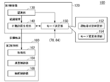
図1は、実施形態に係る車両制御装置を利用した車両システム1の構成図である。車両システム1が搭載される車両は、例えば、二輪や三輪、四輪等の車両であり、その駆動源は、ディーゼルエンジンやガソリンエンジンなどの内燃機関、電動機、或いはこれらの組み合わせである。電動機は、内燃機関に連結された発電機による発電電力、或いは二次電池や燃料電池の放電電力を使用して動作する。[overall structure]
FIG. 1 is a configuration diagram of a
車両システム1は、例えば、カメラ10と、レーダ装置12と、LIDAR(Light Detection and Ranging)14と、物体認識装置16と、通信装置20と、HMI(Human Machine Interface)30と、車両センサ40と、ナビゲーション装置50と、MPU(Map Positioning Unit)60と、ドライバモニタカメラ70と、運転操作子80と、自動運転制御装置100と、走行駆動力出力装置200と、ブレーキ装置210と、ステアリング装置220とを備える。これらの装置や機器は、CAN(Controller Area Network)通信線等の多重通信線やシリアル通信線、無線通信網等によって互いに接続される。図1に示す構成はあくまで一例であり、構成の一部が省略されてもよいし、更に別の構成が追加されてもよい。
The
カメラ10は、例えば、CCD(Charge Coupled Device)やCMOS(Complementary Metal Oxide Semiconductor)等の固体撮像素子を利用したデジタルカメラである。カメラ10は、車両システム1が搭載される車両(以下、自車両M)の任意の箇所に取り付けられる。前方を撮像する場合、カメラ10は、フロントウインドシールド上部やルームミラー裏面等に取り付けられる。カメラ10は、例えば、周期的に繰り返し自車両Mの周辺を撮像する。カメラ10は、ステレオカメラであってもよい。
The
レーダ装置12は、自車両Mの周辺にミリ波などの電波を放射すると共に、物体によって反射された電波(反射波)を検出して少なくとも物体の位置(距離および方位)を検出する。レーダ装置12は、自車両Mの任意の箇所に取り付けられる。レーダ装置12は、FM-CW(Frequency Modulated Continuous Wave)方式によって物体の位置および速度を検出してもよい。
The
LIDAR14は、自車両Mの周辺に光(或いは光に近い波長の電磁波)を照射し、散乱光を測定する。LIDAR14は、発光から受光までの時間に基づいて、対象までの距離を検出する。照射される光は、例えば、パルス状のレーザー光である。LIDAR14は、自車両Mの任意の箇所に取り付けられる。
The LIDAR 14 irradiates the periphery of the own vehicle M with light (or an electromagnetic wave having a wavelength close to that of light) and measures the scattered light. The LIDAR 14 detects the distance to the target based on the time from light emission to light reception. The emitted light is, for example, a pulsed laser beam. The
物体認識装置16は、カメラ10、レーダ装置12、およびLIDAR14のうち一部または全部による検出結果に対してセンサフュージョン処理を行って、物体の位置、種類、速度などを認識する。物体認識装置16は、認識結果を自動運転制御装置100に出力する。物体認識装置16は、カメラ10、レーダ装置12、およびLIDAR14の検出結果をそのまま自動運転制御装置100に出力してよい。車両システム1から物体認識装置16が省略されてもよい。
The
通信装置20は、例えば、セルラー網やWi-Fi網、Bluetooth(登録商標)、DSRC(Dedicated Short Range Communication)などを利用して、自車両Mの周辺に存在する他車両と通信し、或いは無線基地局を介して各種サーバ装置と通信する。
The
HMI30は、自車両Mの乗員に対して各種情報を提示すると共に、乗員による入力操作を受け付ける。HMI30は、各種表示装置、スピーカ、ブザー、タッチパネル、スイッチ、キーなどを含む。
The
車両センサ40は、自車両Mの速度を検出する車速センサ、加速度を検出する加速度センサ、鉛直軸回りの角速度を検出するヨーレートセンサ、自車両Mの向きを検出する方位センサ等を含む。
The
ナビゲーション装置50は、例えば、GNSS(Global Navigation Satellite System)受信機51と、ナビHMI52と、経路決定部53とを備える。ナビゲーション装置50は、HDD(Hard Disk Drive)やフラッシュメモリなどの記憶装置に第1地図情報54を保持している。GNSS受信機51は、GNSS衛星から受信した信号に基づいて、自車両Mの位置を特定する。自車両Mの位置は、車両センサ40の出力を利用したINS(Inertial Navigation System)によって特定または補完されてもよい。ナビHMI52は、表示装置、スピーカ、タッチパネル、キーなどを含む。ナビHMI52は、前述したHMI30と一部または全部が共通化されてもよい。経路決定部53は、例えば、GNSS受信機51により特定された自車両Mの位置(或いは入力された任意の位置)から、ナビHMI52を用いて乗員により入力された目的地までの経路(以下、地図上経路)を、第1地図情報54を参照して決定する。第1地図情報54は、例えば、道路を示すリンクと、リンクによって接続されたノードとによって道路形状が表現された情報である。第1地図情報54は、道路の曲率やPOI(Point Of Interest)情報などを含んでもよい。地図上経路は、MPU60に出力される。ナビゲーション装置50は、地図上経路に基づいて、ナビHMI52を用いた経路案内を行ってもよい。ナビゲーション装置50は、例えば、乗員の保有するスマートフォンやタブレット端末等の端末装置の機能によって実現されてもよい。ナビゲーション装置50は、通信装置20を介してナビゲーションサーバに現在位置と目的地を送信し、ナビゲーションサーバから地図上経路と同等の経路を取得してもよい。
The
MPU60は、例えば、推奨車線決定部61を含み、HDDやフラッシュメモリなどの記憶装置に第2地図情報62を保持している。推奨車線決定部61は、ナビゲーション装置50から提供された地図上経路を複数のブロックに分割し(例えば、車両進行方向に関して100[m]毎に分割し)、第2地図情報62を参照してブロックごとに推奨車線を決定する。推奨車線決定部61は、左から何番目の車線を走行するといった決定を行う。推奨車線決定部61は、地図上経路に分岐箇所が存在する場合、自車両Mが、分岐先に進行するための合理的な経路を走行できるように、推奨車線を決定する。
The
第2地図情報62は、第1地図情報54よりも高精度な地図情報である。第2地図情報62は、例えば、車線の中央の情報あるいは車線の境界の情報等を含んでいる。第2地図情報62には、道路情報、交通規制情報、住所情報(住所・郵便番号)、施設情報、電話番号情報、後述するモードAまたはモードBが禁止される禁止区間の情報などが含まれてよい。第2地図情報62は、通信装置20が他装置と通信することにより、随時、アップデートされてよい。
The
ドライバモニタカメラ70は、例えば、CCDやCMOS等の固体撮像素子を利用したデジタルカメラである。ドライバモニタカメラ70は、自車両Mの運転席に着座した乗員(以下、運転者)の頭部を正面から(顔面を撮像する向きで)撮像可能な位置および向きで、自車両Mにおける任意の箇所に取り付けられる。例えば、ドライバモニタカメラ70は、自車両Mのインストルメントパネルの中央部に設けられたディスプレイ装置の上部に取り付けられる。
The
運転操作子80は、例えば、ステアリングホイール82の他、アクセルペダル、ブレーキペダル、シフトレバー、その他の操作子を含む。運転操作子80には、操作量あるいは操作の有無を検出するセンサが取り付けられており、その検出結果は、自動運転制御装置100、もしくは、走行駆動力出力装置200、ブレーキ装置210、およびステアリング装置220のうち一部または全部に出力される。ステアリングホイール82は、「運転者による操舵操作を受け付ける操作子」の一例である。操作子は、必ずしも環状である必要は無く、異形ステアリングホイールやジョイスティック、ボタンなどの形態であってもよい。ステアリングホイール82には、ステアリング把持センサ84が取り付けられている。ステアリング把持センサ84は、静電容量センサなどにより実現され、運転者がステアリングホイール82を把持している(力を加えられる状態で接していることをいう)か否かを検知可能な信号を自動運転制御装置100に出力する。
The driving
自動運転制御装置100は、例えば、第1制御部120と、第2制御部160とを備える。第1制御部120と第2制御部160は、それぞれ、例えば、CPU(Central Processing Unit)などのハードウェアプロセッサがプログラム(ソフトウェア)を実行することにより実現される。これらの構成要素のうち一部または全部は、LSI(Large Scale Integration)やASIC(Application Specific Integrated Circuit)、FPGA(Field-Programmable Gate Array)、GPU(Graphics Processing Unit)などのハードウェア(回路部;circuitryを含む)によって実現されてもよいし、ソフトウェアとハードウェアの協働によって実現されてもよい。プログラムは、予め自動運転制御装置100のHDDやフラッシュメモリなどの記憶装置(非一過性の記憶媒体を備える記憶装置)に格納されていてもよいし、DVDやCD-ROMなどの着脱可能な記憶媒体に格納されており、記憶媒体(非一過性の記憶媒体)がドライブ装置に装着されることで自動運転制御装置100のHDDやフラッシュメモリにインストールされてもよい。自動運転制御装置100は「車両制御装置」の一例であり、行動計画生成部140と第2制御部160を合わせたものが「運転制御部」の一例である。
The automatic
図2は、第1制御部120および第2制御部160の機能構成図である。第1制御部120は、例えば、認識部130と、行動計画生成部140と、モード決定部150とを備える。第1制御部120は、例えば、AI(Artificial Intelligence;人工知能)による機能と、予め与えられたモデルによる機能とを並行して実現する。例えば、「交差点を認識する」機能は、ディープラーニング等による交差点の認識と、予め与えられた条件(パターンマッチング可能な信号、道路標示などがある)に基づく認識とが並行して実行され、双方に対してスコア付けして総合的に評価することで実現されてよい。これによって、自動運転の信頼性が担保される。
FIG. 2 is a functional configuration diagram of the
認識部130は、カメラ10、レーダ装置12、およびLIDAR14から物体認識装置16を介して入力された情報に基づいて、自車両Mの周辺にある物体の位置、および速度、加速度等の状態を認識する。物体の位置は、例えば、自車両Mの代表点(重心や駆動軸中心など)を原点とした絶対座標上の位置として認識され、制御に使用される。物体の位置は、その物体の重心やコーナー等の代表点で表されてもよいし、領域で表されてもよい。物体の「状態」とは、物体の加速度やジャーク、あるいは「行動状態」(例えば車線変更をしている、またはしようとしているか否か)を含んでもよい。
The
認識部130は、例えば、自車両Mが走行している車線(走行車線)を認識する。例えば、認識部130は、第2地図情報62から得られる道路区画線のパターン(例えば実線と破線の配列)と、カメラ10によって撮像された画像から認識される自車両Mの周辺の道路区画線のパターンとを比較することで、走行車線を認識する。認識部130は、道路区画線に限らず、道路区画線や路肩、縁石、中央分離帯、ガードレールなどを含む走路境界(道路境界)を認識することで、走行車線を認識してもよい。この認識において、ナビゲーション装置50から取得される自車両Mの位置やINSによる処理結果が加味されてもよい。認識部130は、一時停止線、障害物、赤信号、料金所、その他の道路事象を認識する。
The
認識部130は、走行車線を認識する際に、走行車線に対する自車両Mの位置や姿勢を認識する。認識部130は、例えば、自車両Mの基準点の車線中央からの乖離、および自車両Mの進行方向の車線中央を連ねた線に対してなす角度を、走行車線に対する自車両Mの相対位置および姿勢として認識してもよい。これに代えて、認識部130は、走行車線のいずれかの側端部(道路区画線または道路境界)に対する自車両Mの基準点の位置などを、走行車線に対する自車両Mの相対位置として認識してもよい。
When recognizing the traveling lane, the
認識部130は、自車両Mが走行する経路を含む周辺の道路に設置された標識を認識する。認識部130は、路肩などの道路脇や道路の上方など、道路面よりも高い位置に設置された標識の他にも、道路面に描かれた標示も、標識として認識する。認識部130は、走行車線に設置された標識に加えて、例えば、走行車線の進行方向と同じ方向に走行可能な車線(以下、本線車線)、走行車線や本線車線から分岐する車線(以下、分岐車線)、走行車線や本線車線に合流する車線(以下、合流車線)に設置された標識を認識する。認識部130は、自車両Mの進行方向と同じ方向、つまり、自車両Mの前方の標識と、自車両Mが走行してきた後方の標識とのそれぞれを認識する。
The
行動計画生成部140は、原則的には推奨車線決定部61により決定された推奨車線を走行し、更に、自車両Mの周辺状況に対応できるように、自車両Mが自動的に(運転者の操作に依らずに)将来走行する目標軌道を生成する。目標軌道は、例えば、速度要素を含んでいる。例えば、目標軌道は、自車両Mの到達すべき地点(軌道点)を順に並べたものとして表現される。軌道点は、道なり距離で所定の走行距離(例えば数[m]程度)ごとの自車両Mの到達すべき地点であり、それとは別に、所定のサンプリング時間(例えば0コンマ数[sec]程度)ごとの目標速度および目標加速度が、目標軌道の一部として生成される。軌道点は、所定のサンプリング時間ごとの、そのサンプリング時刻における自車両Mの到達すべき位置であってもよい。この場合、目標速度や目標加速度の情報は軌道点の間隔で表現される。
In principle, the action
行動計画生成部140は、目標軌道を生成するにあたり、自動運転のイベントを設定してよい。自動運転のイベントには、定速走行イベント、低速追従走行イベント、車線変更イベント、分岐イベント、合流イベント、テイクオーバーイベントなどがある。行動計画生成部140は、起動させたイベントに応じた目標軌道を生成する。
The action
モード決定部150は、自車両Mの運転モードを、運転者に課されるタスクが異なる複数の運転モードのいずれかに決定する。モード決定部150は、例えば、運転者状態判定部152と、モード変更処理部154とを備える。これらの個別の機能については後述する。
The
図3は、運転モードと自車両Mの制御状態、およびタスクの対応関係の一例を示す図である。自車両Mの運転モードには、例えば、モードAからモードEの5つのモードがある。制御状態すなわち自車両Mの運転制御の自動化度合いは、モードAが最も高く、次いでモードB、モードC、モードDの順に低くなり、モードEが最も低い。この逆に、運転者に課されるタスクは、モードAが最も軽度であり、次いでモードB、モードC、モードDの順に重度となり、モードEが最も重度である。モードDおよびEでは自動運転でない制御状態となるため、自動運転制御装置100としては自動運転に係る制御を終了し、運転支援または手動運転に移行させるまでが責務である。以下、それぞれの運転モードの内容について例示する。
FIG. 3 is a diagram showing an example of the correspondence between the driving mode, the control state of the own vehicle M, and the task. The operation mode of the own vehicle M includes, for example, five modes from mode A to mode E. The degree of automation of the control state, that is, the operation control of the own vehicle M, is highest in mode A, then in the order of mode B, mode C, and mode D, and is lowest in mode E. On the contrary, the task imposed on the driver is the mildest in mode A, followed by mode B, mode C, and mode D in that order, and mode E is the most severe. In modes D and E, the control state is not automatic operation, so the automatic
モードAでは、自動運転の状態となり、運転者には前方監視、ステアリングホイール82の把持(図ではステアリング把持)のいずれも課されない。但し、モードAであっても運転者は、自動運転制御装置100を中心としたシステムからの要求に応じて速やかに手動運転に移行できる体勢であることが要求される。ここで言う自動運転とは、操舵、加減速のいずれも運転者の操作に依らずに制御されることをいう。前方とは、フロントウインドシールドを介して視認される自車両Mの進行方向の空間を意味する。モードAは、例えば、高速道路などの自動車専用道路において、所定速度(例えば50[km/h]程度)以下で自車両Mが走行しており、追従対象の前走車両が存在するなどの条件が満たされる場合に実行可能な運転モードであり、TJP(Traffic Jam Pilot)と称される場合もある。この条件が満たされなくなった場合、モード決定部150は、モードBに自車両Mの運転モードを変更する。
In the mode A, the automatic driving state is set, and neither the forward monitoring nor the gripping of the steering wheel 82 (steering gripping in the figure) is imposed on the driver. However, even in mode A, the driver is required to be in a position to quickly shift to manual driving in response to a request from the system centered on the automatic
モードBでは、運転支援の状態となり、運転者には自車両Mの前方を監視するタスク(以下、前方監視)が課されるが、ステアリングホイール82を把持するタスクは課されない。モードCでは、運転支援の状態となり、運転者には前方監視のタスクと、ステアリングホイール82を把持するタスクが課される。モードDは、自車両Mの操舵と加減速のうち少なくとも一方に関して、ある程度の運転者による運転操作が必要な運転モードである。例えば、モードDでは、ACC(Adaptive Cruise Control)やLKAS(Lane Keeping Assist System)といった運転支援が行われる。モードEでは、操舵、加減速ともに運転者による運転操作が必要な手動運転の状態となる。モードD、モードEともに、当然ながら運転者には自車両Mの前方を監視するタスクが課される。
In the mode B, the driving support state is set, and the driver is tasked with monitoring the front of the own vehicle M (hereinafter referred to as “forward monitoring”), but is not tasked with gripping the
自動運転制御装置100(および運転支援装置(不図示))は、運転モードに応じた自動車線変更を実行する。自動車線変更には、システム要求による自動車線変更(1)と、運転者要求による自動車線変更(2)がある。自動車線変更(1)には、前走車両の速度が自車両の速度に比して基準以上に小さい場合に行われる、追い越しのための自動車線変更と、目的地に向けて進行するための自動車線変更(推奨車線が変更されたことによる自動車線変更)とがある。自動車線変更(2)は、速度や周辺車両との位置関係等に関する条件が満たされた場合において、運転者により方向指示器が操作された場合に、操作方向に向けて自車両Mを車線変更させるものである。 The automatic driving control device 100 (and a driving support device (not shown)) executes a lane change according to a driving mode. The lane change includes a lane change (1) according to a system request and a lane change (2) according to a driver request. The lane change (1) is to change the lane for overtaking and to proceed toward the destination, which is performed when the speed of the vehicle in front is smaller than the standard with respect to the speed of the own vehicle. There is a lane change (a lane change due to a change in the recommended lane). The lane change (2) changes the lane of the own vehicle M toward the operation direction when the direction indicator is operated by the driver when the conditions related to the speed and the positional relationship with the surrounding vehicles are satisfied. It is something that makes you.
自動運転制御装置100は、モードAにおいて、自動車線変更(1)および(2)のいずれも実行しない。自動運転制御装置100は、モードBおよびCにおいて、自動車線変更(1)および(2)のいずれも実行する。運転支援装置(不図示)は、モードDにおいて、自動車線変更(1)は実行せず自動車線変更(2)を実行する。モードEにおいて、自動車線変更(1)および(2)のいずれも実行されない。
The automatic
モード決定部150は、決定した運転モード(以下、現運転モード)に係るタスクが運転者により実行されない場合に、よりタスクが重度な運転モードに自車両Mの運転モードを変更する。
The
例えば、モードAにおいて運転者が、システムからの要求に応じて手動運転に移行できない体勢である場合(例えば、許容エリア外の脇見を継続している場合や、運転困難となる予兆が検出された場合)、モード決定部150は、HMI30を用いて運転者に手動運転への移行を促し、運転者が応じなければ自車両Mを路肩に寄せて徐々に停止させ、自動運転を停止する、といった制御を行う。自動運転を停止した後は、自車両はモードDまたはEの状態になり、運転者の手動操作によって自車両Mを発進させることが可能となる。以下、「自動運転を停止」に関して同様である。モードBにおいて運転者が前方を監視していない場合、モード決定部150は、HMI30を用いて運転者に前方監視を促し、運転者が応じなければ自車両Mを路肩に寄せて徐々に停止させ、自動運転を停止する、といった制御を行う。モードCにおいて運転者が前方を監視していない場合、或いはステアリングホイール82を把持していない場合、モード決定部150は、HMI30を用いて運転者に前方監視を、および/またはステアリングホイール82を把持するように促し、運転者が応じなければ自車両Mを路肩に寄せて徐々に停止させ、自動運転を停止する、といった制御を行う。
For example, in mode A, when the driver is in a position where he / she cannot shift to manual driving in response to a request from the system (for example, when he / she continues to look outside the permissible area, or when a sign that driving becomes difficult is detected. (Case), the
運転者状態判定部152は、上記のモード変更のために運転者の状態を監視し、運転者の状態がタスクに応じた状態であるか否かを判定する。例えば、運転者状態判定部152は、ドライバモニタカメラ70が撮像した画像を解析して姿勢推定処理を行い、運転者が、システムからの要求に応じて手動運転に移行できない体勢であるか否かを判定する。運転者状態判定部152は、ドライバモニタカメラ70が撮像した画像を解析して視線推定処理を行い、運転者が前方を監視しているか否かを判定する。
The driver
モード変更処理部154は、モード変更のための各種処理を行う。例えば、モード変更処理部154は、行動計画生成部140に路肩停止のための目標軌道を生成するように指示したり、運転支援装置(不図示)に作動指示をしたり、運転者に行動を促すためにHMI30の制御をしたりする。
The mode
第2制御部160は、行動計画生成部140によって生成された目標軌道を、予定の時刻通りに自車両Mが通過するように、走行駆動力出力装置200、ブレーキ装置210、およびステアリング装置220を制御する。
The
図2に戻り、第2制御部160は、例えば、取得部162と、速度制御部164と、操舵制御部166とを備える。取得部162は、行動計画生成部140により生成された目標軌道(軌道点)の情報を取得し、メモリ(不図示)に記憶させる。速度制御部164は、メモリに記憶された目標軌道に付随する速度要素に基づいて、走行駆動力出力装置200またはブレーキ装置210を制御する。操舵制御部166は、メモリに記憶された目標軌道の曲がり具合に応じて、ステアリング装置220を制御する。速度制御部164および操舵制御部166の処理は、例えば、フィードフォワード制御とフィードバック制御との組み合わせにより実現される。一例として、操舵制御部166は、自車両Mの前方の道路の曲率に応じたフィードフォワード制御と、目標軌道からの乖離に基づくフィードバック制御とを組み合わせて実行する。
Returning to FIG. 2, the
走行駆動力出力装置200は、車両が走行するための走行駆動力(トルク)を駆動輪に出力する。走行駆動力出力装置200は、例えば、内燃機関、電動機、および変速機などの組み合わせと、これらを制御するECU(Electronic Control Unit)とを備える。ECUは、第2制御部160から入力される情報、或いは運転操作子80から入力される情報に従って、上記の構成を制御する。
The traveling driving
ブレーキ装置210は、例えば、ブレーキキャリパーと、ブレーキキャリパーに油圧を伝達するシリンダと、シリンダに油圧を発生させる電動モータと、ブレーキECUとを備える。ブレーキECUは、第2制御部160から入力される情報、或いは運転操作子80から入力される情報に従って電動モータを制御し、制動操作に応じたブレーキトルクが各車輪に出力されるようにする。ブレーキ装置210は、運転操作子80に含まれるブレーキペダルの操作によって発生させた油圧を、マスターシリンダを介してシリンダに伝達する機構をバックアップとして備えてよい。ブレーキ装置210は、上記説明した構成に限らず、第2制御部160から入力される情報に従ってアクチュエータを制御して、マスターシリンダの油圧をシリンダに伝達する電子制御式油圧ブレーキ装置であってもよい。
The
ステアリング装置220は、例えば、ステアリングECUと、電動モータとを備える。電動モータは、例えば、ラックアンドピニオン機構に力を作用させて転舵輪の向きを変更する。ステアリングECUは、第2制御部160から入力される情報、或いは運転操作子80から入力される情報に従って、電動モータを駆動し、転舵輪の向きを変更させる。
The
モードA~Cのいずれかまたは複数は、特許請求の範囲における「第2の運転モード」の一例であり、モードC~Eのいずれかまたは複数は、特許請求の範囲における「第1の運転モード」の一例である。ここで、モードCが特許請求の範囲における「第2の運転モード」である場合、特許請求の範囲における「第1の運転モード」はモードDまたはEのいずれかである。以下の説明においては、一例として、特許請求の範囲における「第2の運転モード」がモードAまたはBであり、特許請求の範囲における「第1の運転モード」がモードCであるものとする。 One or more of modes A to C is an example of a "second operation mode" in the claims, and any or more of modes C to E is a "first operation mode" in the claims. Is an example. Here, when the mode C is the "second operation mode" in the claims, the "first operation mode" in the claims is either mode D or E. In the following description, as an example, it is assumed that the "second operation mode" in the claims is mode A or B, and the "first operation mode" in the claims is mode C.
<第1実施形態>
[運転モードの制御]
以下、自車両Mの周辺の標識の数に応じた自車両Mの運転モードの制御について説明する。以下の説明においては、自車両MがモードAまたはBで走行している場合において、モードAまたはBでの走行を終了してモードCに変更する場合について説明する。<First Embodiment>
[Control of operation mode]
Hereinafter, control of the operation mode of the own vehicle M according to the number of signs around the own vehicle M will be described. In the following description, when the own vehicle M is traveling in the mode A or B, the case where the traveling in the mode A or B is terminated and the mode is changed to the mode C will be described.
認識部130は、自車両Mが走行する経路における標識を認識する。標識には、道路に設置された規制標識、警戒標識、指示標識、補助標識、案内標識などの道路標識と、道路面に描かれた規制標示、指示標示などの路面標示(道路標示)とが含まれる。認識部130は、自車両Mが走行する経路において、自車両Mを基準とした基準距離の範囲(基準範囲)内に存在する標識を認識する。
The
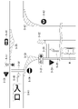
図4および図5は、第1実施形態に係る認識部130が認識する標識について説明するための図である。
4 and 5 are diagrams for explaining a sign recognized by the
図4は、自車両Mが自動車専用道路を走行している場面である。図4においては、連続して連なっている一連の矢印が車線を示している。図4の例では、車線L-1~L-5は、本線車線である。この中で、車線L-1は自車両Mの走行車線であり、車線L-2~L-5は、自車両Mの走行車線と同じ方向に走行可能な本線車線である。車線L-6~L-10と、車線L-15およびL-16とは、本線車線から分岐する、あるいは分岐した分岐車線である。車線L-11~L-14は、本線車線に合流する、あるいは合流した合流車線である。この場面において、自車両Mは現在の走行車線(車線L-1)を進行方向TDの方向に走行している。認識部130は、自車両Mの前方における前方基準距離DFの範囲内に存在する標識Sと、自車両Mの後方における後方基準距離DRの範囲内に存在する標識Sとのそれぞれを認識する。前方基準距離DFは、後方基準距離DRよりも長い距離である。例えば、前方基準距離DFと後方基準距離DRとは、ともに数百[m]程度の距離である。認識部130は、走行車線、本線車線、分岐車線、および合流車線に設置あるいは描かれたそれぞれの標識Sを認識する。自車両Mが図4に示した位置である場合、認識部130は、前方基準距離DFの範囲において標識S-1~S-16を認識し、後方基準距離DRの範囲において標識S-17~S-27を認識する。
FIG. 4 shows a scene in which the own vehicle M is traveling on a motorway. In FIG. 4, a series of continuous arrows indicate a lane. In the example of FIG. 4, lanes L-1 to L-5 are main lanes. Among them, the lane L-1 is the traveling lane of the own vehicle M, and the lanes L-2 to L-5 are the main lanes capable of traveling in the same direction as the traveling lane of the own vehicle M. Lanes L-6 to L-10 and lanes L-15 and L-16 are branch lanes that branch off from or branch off from the main lane. Lanes L-11 to L-14 are merging lanes that merge or merge with the main lane. In this scene, the own vehicle M is traveling in the current traveling lane (lane L-1) in the direction of travel TD. The
図5は、自車両MがT型の交差点に進入する場面である。図5においては、認識部130が標識Sを認識する前方基準距離DFの範囲のみを示している。自車両Mが図5に示した位置である場合、認識部130は、前方基準距離DFの範囲において標識S-28~S-43を認識する。
FIG. 5 shows a scene in which the own vehicle M enters a T-shaped intersection. In FIG. 5, only the range of the forward reference distance DF in which the
認識部130は、認識した標識に関する情報(以下、標識情報)を、モード決定部150に出力する。標識情報には、少なくとも、認識した標識Sの数(以下、標識数)の情報が含まれる。標識情報には、例えば、認識したそれぞれの標識Sが本線車線、分岐車線、合流車線のいずれに設置されている、あるいは描かれている標識であるかを表す車線区分情報や、標識Sが前方基準距離DFまたは後方基準距離DRのいずれの範囲に存在する標識であるか、それぞれの標識Sにおける自車両Mの位置からの距離(前方あるいは後方の情報を含んでもよい)などの自車両Mとの位置関係を表す標識位置情報などを含んでもよい。
The
モード決定部150は、認識部130により出力された標識情報に基づいて、自車両Mの運転モードを変更する。より具体的には、モード決定部150は、現在の自車両Mの運転モードがモードAまたはBであり、且つ標識情報に含まれる標識数が第1基準値を超えるか否かを判定する。第1基準値は、例えば、数[個]から数十[個]程度の値である。第1基準値は、固定値であってもよいし、自車両Mの周辺の車線の数など、自車両Mが現在走行している状況に応じて定められてもよい。第1基準値は、推奨車線決定部61が推奨車線を決定する際に参照する第2地図情報62のブロックごとに定められてもよい。
The
モード決定部150は、自車両Mの運転モードがモードAまたはBであり、且つ標識数が第1基準値を超える場合に、現在の自車両Mの運転モードを、モードAまたはBからモードCに変更する。これにより、運転者は、標識数が第1基準値を超える範囲を通過する際に、前方を監視するとともにステアリングホイール82を把持することになる。このことにより、運転者は、周辺環境に変化があった場合でも、自身でステアリングホイール82を操作して対処することができる。
When the operation mode of the own vehicle M is the mode A or B and the number of signs exceeds the first reference value, the
モード決定部150は、モードAまたはBからモードCに運転モードを変更するのに代えて、モードAまたはBからモードDまたはEに運転モードを変更するようにしてもよい。この場合、モード決定部150は、モードAまたはBからモードDまたはEに運転モードを変更するまでの間に、一旦モードCに変更してから、モードDまたはEに変更してもよい。
The
モード決定部150は、認識部130により出力された標識情報に含まれる標識数が第1基準値以下となったことを条件として、モードCに変更した運転モードを、再びモードAまたはBに変更してもよい。これにより、自車両Mにおける利便性を向上させることができる。モード決定部150は、モードCからモードAまたはBに運転モードを変更するための条件として、運転者におけるHMI30に対する操作を促すようにしてもよい。これにより、運転モードの切り替えによる制御の乱れが生じるのを抑制することができる。
The
[運転モードの変更処理]
図6は、第1実施形態に係るモード決定部150により実行される処理の流れの一例を示すフローチャートである。本フローチャートの変更処理は、例えば、自動運転制御装置100が作動している間、繰り返し実行される。[Operation mode change process]
FIG. 6 is a flowchart showing an example of the flow of processing executed by the
まず、モード決定部150は、現在の自車両Mの運転モードがモードAまたはBであるか否かを判定する(ステップS100)。ステップS100において、現在の自車両Mの運転モードがモードAまたはBではない場合、モード決定部150は、ステップS100の判定を繰り返す。
First, the
一方、ステップS100において、現在の自車両Mの運転モードがモードAまたはBであると判定された場合、モード決定部150は、認識部130により出力された標識情報を取得する(ステップS102)。そして、モード決定部150は、取得した標識情報に含まれる標識数が第1基準値を超えるか否かを判定する(ステップS104)。ステップS104において、標識数が第1基準値を超えないと判定された場合、モード決定部150は、処理をステップS100に戻す。
On the other hand, when it is determined in step S100 that the current driving mode of the own vehicle M is mode A or B, the
一方、ステップS104において、標識数が第1基準値を超えると判定された場合、モード決定部150は、自車両Mの運転モードをモードCに変更する(ステップS106)。
On the other hand, when it is determined in step S104 that the number of signs exceeds the first reference value, the
その後、モード決定部150は、認識部130により出力された標識情報を再度取得する(ステップS108)。このステップS108の処理は、ステップS106の処理において自車両Mの運転モードをモードCに変更した後、所定の時間が経過した後に行ってもよい。所定の時間とは、例えば、数[sec]から十数[sec]程度の時間である。所定の時間は、例えば、認識部130が認識した標識数が異なる値になるまでの時間であってもよい。
After that, the
そして、モード決定部150は、再度取得した標識情報に含まれる標識数が第1基準値以下であるか否かを判定する(ステップS110)。ステップS110において、標識数が第1基準値以下ではないと判定された場合、モード決定部150は、処理をステップS100に戻す。つまり、モード決定部150は、変更した現在の走行モード(モードC)を維持する。
Then, the
一方、ステップS110において、標識数が第1基準値以下であると判定された場合、モード決定部150は、自車両Mの運転モードをモードAまたはBに変更し(ステップS112)、処理をステップS100に戻す。
On the other hand, when it is determined in step S110 that the number of signs is equal to or less than the first reference value, the
以上説明した処理によって、モード決定部150は、現在の自車両Mの運転モードがモードAまたはBであるときに、自車両Mの周辺の標識数が第1基準値を超える場合には、自車両Mの運転モードをモードCに変更する。これにより、運転者は、前方を監視するとともにステアリングホイール82を把持する状態となり、周辺環境の変化に対応可能となる。この結果、自動運転制御装置100では、道路構造に応じた適切な制御をすることができる。
By the process described above, the
図6に示した変更処理の一例では、自車両Mの周辺の標識数が第1基準値を超える場合に自車両Mの運転モードをモードCに変更した。モード決定部150は、例えば、二段階で自車両Mの運転モードを変更するようにしてもよい。この場合、モード決定部150は、例えば、自車両Mの周辺の標識数が第2基準値を超えた場合に、第1段階として自車両Mの運転モードをモードAまたはBからモードCに変更し、さらに自車両Mの周辺の標識数が第1基準値を超えた場合に、第2段階として自車両Mの運転モードをモードCからモードDまたはEに変更するようにしてもよい。第2基準値は、第1基準値よりも少ない値である。第2基準値は、例えば、数[個]から数十[個]程度の値である。第2基準値も、第1基準値と同様に、固定値であってもよいし、自車両Mの周辺の車線の数など、自車両Mが現在走行している状況に応じて定められてもよいし、第2地図情報62のブロックごとに定められてもよい。この場合における認識部130の標識の認識方法や、モード決定部150の処理などは、上述した変更処理の一例と等価なものになるようにすればよい。
In the example of the change process shown in FIG. 6, when the number of signs around the own vehicle M exceeds the first reference value, the operation mode of the own vehicle M is changed to the mode C. The
<第2実施形態>
第1実施形態におけるモード決定部150は、自車両MがモードAまたはBで走行しているときに、認識部130が認識した標識数に基づいて、自車両Mの運転モードをモードCに変更する。第2実施形態に係るモード決定部150は、認識部130が認識した標識数と、第2地図情報62に示された地図上の車線に設置された標識の数(以下、地図上標識数)との相違度合いが条件を満たすか否かによって判定し、相違度合いが条件を満たさない場合に、運転モードをモードCに変更するようにしてもよい。地図上標識数は、自車両Mの前方基準距離DFおよび後方基準距離DRの範囲内の第2地図情報62に示された標識の数である。地図上標識数は、モード決定部150が、MPU60から前方基準距離DFおよび後方基準距離DRの範囲内の第2地図情報62を取得し、取得した第2地図情報62に示された標識の数を計数してもよい。地図上標識数は、MPU60が、モード決定部150により出力された前方基準距離DFおよび後方基準距離DRの情報に基づいて第2地図情報62に示された標識の数を計数してもよいし、推奨車線決定部61が、推奨車線を決定する際に、ブロックごとに標識の数を計数してもよい。相違度合いの条件は、例えば、標識数と地図上標識数との差で定められたものである。標識数と地図上標識数との差は、固定値であってもよいし、標識数あるいは地図上標識数のいずれか一方を基準とし、基準とした一方に対して他方が多い場合と少ない場合とで異なる値にしたものであってもよい。例えば、標識数を基準とした場合、相違度合いの条件は、地図上標識数が多い場合の上限値と、地図上標識数が少ない場合の下限値とのそれぞれの値で定められてもよい。この場合、モード決定部150は、標識数と地図上標識数との差が上限値から下限値までの間であれば相違度合いの条件を満たすと判定し、地図上標識数が、標識数よりも上限値以上多い、あるいは標識数よりも下限値以上少ない場合に、相違度合いが条件を満たさないと判定する。地図上標識数を基準とした場合も、同様である。<Second Embodiment>
The
相違度合いが条件を満たさない場合の事象としては、以下のような一例が考えられる。例えば、第2地図情報62の不具合によって、第2地図情報62に示された地図上の車線に設置された標識の情報が現在の道路の状態に合致していない場合や、路肩の植物によって実際の標識が認識しづらくなっている場合などでは、地図上標識数が標識数よりも多くなる(認識部130が認識できた標識数が地図上標識数よりも少なくなる)。例えば、第2地図情報62の不具合によって、第2地図情報62に示された地図上の車線に設置された標識の情報が現在の道路の状態に合致していない場合や、標識が新たに設置された場合などでは、地図上標識数が標識数よりも少なくなる(認識部130が認識できた標識数が地図上標識数よりも多くなる)。第2地図情報62の不具合としては、例えば、標識の情報が壊れていたり、自車両Mが走行している地域の地図情報が欠落していたりするなどの要因が考えられる。
The following is an example of an event when the degree of difference does not satisfy the conditions. For example, when the information of the sign installed in the lane on the map shown in the
[運転モードの変更処理]
図7は、第1実施形態に係るモード決定部150により実行される処理の流れの一例を示すフローチャートである。本フローチャートの変更処理も、第1実施形態の変更処理と同様に、例えば、自動運転制御装置100が作動している間、繰り返し実行される。本フローチャートには、第1実施形態の変更処理と同様の処理を含んでいる。従って、本フローチャートにおける第1実施形態の変更処理と同様の処理には、同一のステップ番号を付与し、同様の処理に関する再度の説明は省略する。[Operation mode change process]
FIG. 7 is a flowchart showing an example of the flow of processing executed by the
第2実施形態の変更処理では、モード決定部150は、ステップS100において、現在の自車両Mの運転モードがモードAまたはBであると判定された場合に、ステップS102において、認識部130により出力された標識情報を取得する。
In the change process of the second embodiment, the
その後、モード決定部150は、地図上標識数を取得する(ステップS200)。そして、モード決定部150は、取得した標識情報に含まれる標識数と取得した地図上標識数との相違度合いが条件を満たすか否かを判定する(ステップS202)。ステップS202において、標識数と地図上標識数との相違度合いが条件を満たすと判定された場合、モード決定部150は、処理をステップS100に戻す。
After that, the
一方、ステップS202において、標識数と地図上標識数との相違度合いが条件を満たさないと判定された場合、モード決定部150は、自車両Mの運転モードをモードCに変更する(ステップS106)。
On the other hand, if it is determined in step S202 that the degree of difference between the number of signs and the number of signs on the map does not satisfy the condition, the
そして、モード決定部150は、MPU60に、第2地図情報62の更新を指示する(ステップS208)。このステップS208に指示に応じて、MPU60は、通信装置20に他装置との通信を行わせて、第2地図情報62をアップデートさせる。これにより、車両システム1では、例えば、第2地図情報62の不具合によって第2地図情報62に示された地図上の車線に設置された標識の情報が現在の道路の状態に合致していないということを回避させることができる。MPU60や通信装置20は、特許請求の範囲における「高精度地図情報の取得部」の一例である。
Then, the
その後、モード決定部150は、地図上標識数を再度取得する(ステップS210)。このステップS210の処理は、ステップS208の処理において第2地図情報62の更新をMPU60に指示した後、所定の時間が経過した後に行ってもよい。所定の時間とは、例えば、数[sec]から十数[sec]程度の時間である。所定の時間は、例えば、MPU60により第2地図情報62が更新されるまでの時間であってもよい。
After that, the
そして、モード決定部150は、取得した標識情報に含まれる標識数と再度取得した地図上標識数との相違度合いが条件を満たすか否かを判定する(ステップS212)。ステップS212において、標識数と地図上標識数との相違度合いが条件を満たさないと判定された場合、モード決定部150は、処理をステップS100に戻す。つまり、モード決定部150は、変更した現在の走行モード(モードC)を維持する。
Then, the
一方、ステップS212において、標識数と地図上標識数との相違度合いが条件を満たすと判定された場合、モード決定部150は、第1実施形態の変更処理と同様に、自車両Mの運転モードをモードAまたはBに変更し(ステップS112)、処理をステップS100に戻す。
On the other hand, when it is determined in step S212 that the degree of difference between the number of signs and the number of signs on the map satisfies the condition, the
以上説明した処理によって、第2実施形態のモード決定部150は、現在の自車両Mの運転モードがモードAまたはBであるときに、標識数と地図上標識数との相違度合いが条件を満たさない場合には、自車両Mの運転モードをモードCに変更する。これにより、運転者は、第1実施形態の変更処理と同様に、前方を監視するとともにステアリングホイール82を把持する状態となり、周辺環境の変化に対応可能となる。この結果、第2実施形態に係る自動運転制御装置100は、第1実施形態と同様に、道路構造に応じた適切な制御をすることができる。
By the process described above, the
第2実施形態の変更処理では、ステップS208の処理において第2地図情報62の更新をMPU60に指示した。このMPU60に対する第2地図情報62の更新の指示は、第1実施形態の変更処理において行ってもよい。そして、モード決定部150は、指示に応じてMPU60が第2地図情報62を更新した後、更新されたMPU60に基づいて、第1基準値を更新するようにしてもよい。この場合、モード決定部150は、第1実施形態の変更処理におけるステップS110の処理を、更新した第1基準値を用いて行うことができる。
In the change process of the second embodiment, the
上記に述べたとおり、実施形態の自動運転制御装置100によれば、認識部130が、自車両Mが走行する経路を含む周辺の道路に設置された標識を認識する。そして、実施形態の自動運転制御装置100では、モード決定部150が、現在の自車両Mの運転モードがモードAまたはBである場合に、認識部130が認識した標識の情報に基づいて、自車両Mの運転モードを変更する。これにより、実施形態の自動運転制御装置100では、道路構造に応じた適切な制御をすることができる。
As described above, according to the automatic
上記説明した実施形態は、以下のように表現することができる。
プログラムを記憶した記憶装置と、
ハードウェアプロセッサと、を備え、
前記ハードウェアプロセッサが前記記憶装置に記憶されたプログラムを実行することにより、
車両の周辺の状況を認識し、
前記車両の運転者の操作に依らずに前記車両の操舵および加減速を制御し、
前記車両の運転モードを、第1の運転モードと、第2の運転モードとを含む複数の運転モードのいずれかに決定し、前記第2の運転モードは前記運転者に課されるタスクが前記第1の運転モードに比して軽度な運転モードであり、少なくとも前記第2の運転モードを含む前記複数の運転モードの一部は前記車両の運転者の操作に依らずに前記車両の操舵および加減速を制御することで行われるものであり、
前記決定した運転モードに係るタスクが運転者により実行されない場合に、よりタスクが重度な運転モードに前記車両の運転モードを変更し、
前記認識する際に、前記車両が走行する経路の基準範囲内に存在する標識を認識し、
前記車両の運転モードが前記第2の運転モードである場合、前記認識された前記標識の数が第1基準値を超える場合に、前記第2の運転モードから前記第1の運転モードに前記車両の運転モードを変更する、
ように構成されている、車両制御装置。The embodiment described above can be expressed as follows.
A storage device that stores the program and
With a hardware processor,
By executing the program stored in the storage device by the hardware processor.
Recognize the situation around the vehicle and
It controls the steering and acceleration / deceleration of the vehicle without depending on the operation of the driver of the vehicle.
The driving mode of the vehicle is determined to be one of a plurality of driving modes including a first driving mode and a second driving mode, and the second driving mode is the task assigned to the driver. It is a light driving mode as compared with the first driving mode, and at least a part of the plurality of driving modes including the second driving mode is steering and steering of the vehicle without depending on the operation of the driver of the vehicle. It is done by controlling acceleration / deceleration.
When the task related to the determined driving mode is not executed by the driver, the driving mode of the vehicle is changed to a driving mode in which the task is more severe.
At the time of the recognition, the sign existing in the reference range of the route on which the vehicle travels is recognized, and the sign is recognized.
When the driving mode of the vehicle is the second driving mode, when the number of the recognized signs exceeds the first reference value, the vehicle changes from the second driving mode to the first driving mode. Change the operation mode of
Vehicle control unit configured as such.
以上、本発明を実施するための形態について実施形態を用いて説明したが、本発明はこうした実施形態に何ら限定されるものではなく、本発明の要旨を逸脱しない範囲内において種々の変形および置換を加えることができる。 Although the embodiments for carrying out the present invention have been described above with reference to the embodiments, the present invention is not limited to these embodiments, and various modifications and substitutions are made without departing from the gist of the present invention. Can be added.
1・・・車両システム
10・・・カメラ
12・・・レーダ装置
14・・・LIDAR
16・・・物体認識装置
40・・・車両センサ
60・・・MPU
61・・・推奨車線決定部
62・・・第2地図情報
70・・・ドライバモニタカメラ
80・・・運転操作子
82・・・ステアリングホイール
84・・・ステアリング把持センサ
100・・・自動運転制御装置
120・・・第1制御部
130・・・認識部
140・・・行動計画生成部
150・・・モード決定部
152・・・運転者状態判定部
154・・・モード変更処理部
160・・・第2制御部1 ...
16 ...
61 ... Recommended
Claims (9)
前記車両の運転者の操作に依らずに前記車両の操舵および加減速を制御する運転制御部と、
前記車両の運転モードを、第1の運転モードと、第2の運転モードとを含む複数の運転モードのいずれかに決定し、前記第2の運転モードは前記運転者に課されるタスクが前記第1の運転モードに比して軽度な運転モードであり、少なくとも前記第2の運転モードを含む前記複数の運転モードの一部は前記運転制御部により制御されるものであり、前記決定した運転モードに係るタスクが運転者により実行されない場合に、よりタスクが重度な運転モードに前記車両の運転モードを変更するモード決定部と、
を備え、
前記認識部は、前記車両が走行する経路の基準範囲内に存在する標識を認識し、
前記モード決定部は、前記車両の運転モードが前記第2の運転モードである場合、前記認識部により認識された前記標識の数が第1基準値を超える場合に、前記第2の運転モードから前記第1の運転モードに前記車両の運転モードを変更し、
前記認識部により認識された前記標識の数と、標識情報を含む地図情報に示された前記基準範囲の地図上の車線に設置された標識の数との相違度合いが条件を満たさない場合に、前記運転制御部における前記運転モードを前記第2の運転モードから前記第1の運転モードに変更する、
車両制御装置。 A recognition unit that recognizes the situation around the vehicle and
A driving control unit that controls steering and acceleration / deceleration of the vehicle without depending on the operation of the driver of the vehicle.
The driving mode of the vehicle is determined to be one of a plurality of driving modes including a first driving mode and a second driving mode, and the second driving mode is the task assigned to the driver. It is a light operation mode as compared with the first operation mode, and at least a part of the plurality of operation modes including the second operation mode is controlled by the operation control unit, and the determined operation is performed. A mode determination unit that changes the driving mode of the vehicle to a driving mode in which the task is more severe when the task related to the mode is not executed by the driver.
Equipped with
The recognition unit recognizes a sign existing within the reference range of the route on which the vehicle travels, and recognizes the sign.
When the operation mode of the vehicle is the second operation mode and the number of the signs recognized by the recognition unit exceeds the first reference value, the mode determination unit can be used from the second operation mode. The driving mode of the vehicle is changed to the first driving mode,
When the degree of difference between the number of the signs recognized by the recognition unit and the number of signs installed in the lane on the map of the reference range shown in the map information including the sign information does not satisfy the condition. The operation mode in the operation control unit is changed from the second operation mode to the first operation mode .
Vehicle control unit.
請求項1に記載の車両制御装置。 When the degree of difference in the number of the signs does not satisfy the condition, the mode determination unit causes the map information acquisition unit to acquire new map information.
The vehicle control device according to claim 1 .
前記車両の運転者の操作に依らずに前記車両の操舵および加減速を制御する運転制御部と、
前記車両の運転モードを、第1の運転モードと、第2の運転モードとを含む複数の運転モードのいずれかに決定し、前記第2の運転モードは前記運転者に課されるタスクが前記第1の運転モードに比して軽度な運転モードであり、少なくとも前記第2の運転モードを含む前記複数の運転モードの一部は前記運転制御部により制御されるものであり、前記決定した運転モードに係るタスクが運転者により実行されない場合に、よりタスクが重度な運転モードに前記車両の運転モードを変更するモード決定部と、
を備え、
前記認識部は、前記車両が走行する経路の基準範囲内に存在する標識を認識し、
前記モード決定部は、前記車両の運転モードが前記第2の運転モードである場合、前記認識部により認識された前記標識の数が第1基準値を超える場合に、前記第2の運転モードから前記第1の運転モードに前記車両の運転モードを変更し、
少なくとも地図上の車線に設置された標識の位置の情報を含む地図情報が更新された場合に、第1基準値を更新する、
車両制御装置。 A recognition unit that recognizes the situation around the vehicle and
A driving control unit that controls steering and acceleration / deceleration of the vehicle without depending on the operation of the driver of the vehicle.
The driving mode of the vehicle is determined to be one of a plurality of driving modes including a first driving mode and a second driving mode, and the second driving mode is the task assigned to the driver. It is a light operation mode as compared with the first operation mode, and at least a part of the plurality of operation modes including the second operation mode is controlled by the operation control unit, and the determined operation is performed. A mode determination unit that changes the driving mode of the vehicle to a driving mode in which the task is more severe when the task related to the mode is not executed by the driver.
Equipped with
The recognition unit recognizes a sign existing within the reference range of the route on which the vehicle travels, and recognizes the sign.
When the operation mode of the vehicle is the second operation mode and the number of the signs recognized by the recognition unit exceeds the first reference value, the mode determination unit can be used from the second operation mode. The driving mode of the vehicle is changed to the first driving mode,
The first reference value is updated when the map information including at least the information on the position of the sign installed in the lane on the map is updated.
Vehicle control unit.
請求項1に記載の車両制御装置。 The reference range includes a range from the vehicle to the front reference distance toward the front and a range from the vehicle to the rear reference distance toward the rear.
The vehicle control device according to claim 1.
請求項4に記載の車両制御装置。 The front reference distance is longer than the rear reference distance.
The vehicle control device according to claim 4 .
請求項1に記載の車両制御装置。 The recognition unit recognizes a sign installed at a position higher than the road surface of the route and / or a sign drawn on the road surface.
The vehicle control device according to claim 1.
前記第1の運転モードは、前記運転者により、前記車両の操舵と加減速との内、少なくとも一方の運転操作が必要な運転モード、あるいは、前記運転者による前記操作子の把持が課される運転モードである、
請求項1に記載の車両制御装置。 The second operation mode is, at least, an operation mode in which the operator that accepts the steering operation by the driver is not gripped.
In the first operation mode, the driver imposes an operation mode in which at least one of steering and acceleration / deceleration of the vehicle is required, or the driver grips the operator. Operation mode,
The vehicle control device according to claim 1.
車両の周辺の状況を認識し、
前記車両の運転者の操作に依らずに前記車両の操舵および加減速を制御し、
前記車両の運転モードを、第1の運転モードと、第2の運転モードとを含む複数の運転モードのいずれかに決定し、前記第2の運転モードは前記運転者に課されるタスクが前記第1の運転モードに比して軽度な運転モードであり、少なくとも前記第2の運転モードを含む前記複数の運転モードの一部は前記車両の運転者の操作に依らずに前記車両の操舵および加減速を制御することで行われるものであり、
前記決定した運転モードに係るタスクが運転者により実行されない場合に、よりタスクが重度な運転モードに前記車両の運転モードを変更し、
前記認識する際に、前記車両が走行する経路の基準範囲内に存在する標識を認識し、
前記車両の運転モードが前記第2の運転モードである場合、前記認識された前記標識の数が第1基準値を超える場合に、前記第2の運転モードから前記第1の運転モードに前記車両の運転モードを変更し、
前記認識された前記標識の数と、標識情報を含む地図情報に示された前記基準範囲の地図上の車線に設置された標識の数との相違度合いが条件を満たさない場合に、前記運転モードを前記第2の運転モードから前記第1の運転モードに変更する、
車両制御方法。 The computer installed in the vehicle
Recognize the situation around the vehicle and
It controls the steering and acceleration / deceleration of the vehicle without depending on the operation of the driver of the vehicle.
The driving mode of the vehicle is determined to be one of a plurality of driving modes including a first driving mode and a second driving mode, and the second driving mode is the task assigned to the driver. It is a light driving mode as compared with the first driving mode, and at least a part of the plurality of driving modes including the second driving mode is steering and steering of the vehicle without depending on the operation of the driver of the vehicle. It is done by controlling acceleration / deceleration.
When the task related to the determined driving mode is not executed by the driver, the driving mode of the vehicle is changed to a driving mode in which the task is more severe.
At the time of the recognition, the sign existing in the reference range of the route on which the vehicle travels is recognized, and the sign is recognized.
When the driving mode of the vehicle is the second driving mode, when the number of the recognized signs exceeds the first reference value, the vehicle changes from the second driving mode to the first driving mode. Change the operation mode of
The operation mode is when the degree of difference between the number of recognized signs and the number of signs installed in the lane on the map of the reference range shown in the map information including the sign information does not satisfy the condition. Is changed from the second operation mode to the first operation mode .
Vehicle control method.
車両の周辺の状況を認識させ、
前記車両の運転者の操作に依らずに前記車両の操舵および加減速を制御させ、
前記車両の運転モードを、第1の運転モードと、第2の運転モードとを含む複数の運転モードのいずれかに決定させ、前記第2の運転モードは前記運転者に課されるタスクが前記第1の運転モードに比して軽度な運転モードであり、少なくとも前記第2の運転モードを含む前記複数の運転モードの一部は前記車両の運転者の操作に依らずに前記車両の操舵および加減速を制御することで行われるものであり、
前記決定した運転モードに係るタスクが運転者により実行されない場合に、よりタスクが重度な運転モードに前記車両の運転モードを変更させ、
前記認識する際に、前記車両が走行する経路の基準範囲内に存在する標識を認識させ、
前記車両の運転モードが前記第2の運転モードである場合、前記認識させた前記標識の数が第1基準値を超える場合に、前記第2の運転モードから前記第1の運転モードに前記車両の運転モードを変更させ、
前記認識させた前記標識の数と、標識情報を含む地図情報に示された前記基準範囲の地図上の車線に設置された標識の数との相違度合いが条件を満たさない場合に、前記運転モードを前記第2の運転モードから前記第1の運転モードに変更させる、
プログラム。 On the computer installed in the vehicle,
Recognize the situation around the vehicle
The steering and acceleration / deceleration of the vehicle are controlled without depending on the operation of the driver of the vehicle.
The driving mode of the vehicle is determined to be one of a plurality of driving modes including a first driving mode and a second driving mode, and the second driving mode is the task assigned to the driver. It is a light driving mode as compared with the first driving mode, and at least a part of the plurality of driving modes including the second driving mode is steering and steering of the vehicle without depending on the operation of the driver of the vehicle. It is done by controlling acceleration / deceleration.
When the task related to the determined driving mode is not executed by the driver, the driving mode of the vehicle is changed to a driving mode in which the task is more severe.
At the time of the recognition, the sign existing in the reference range of the route on which the vehicle travels is recognized.
When the driving mode of the vehicle is the second driving mode, when the number of the recognized signs exceeds the first reference value, the vehicle changes from the second driving mode to the first driving mode. Change the operation mode of
The operation mode is when the degree of difference between the number of the recognized signs and the number of signs installed in the lane on the map of the reference range shown in the map information including the sign information does not satisfy the condition. Is changed from the second operation mode to the first operation mode .
program.
Applications Claiming Priority (1)
| Application Number | Priority Date | Filing Date | Title |
|---|---|---|---|
| PCT/JP2020/049098 WO2022144956A1 (en) | 2020-12-28 | 2020-12-28 | Vehicle control device, vehicle control method, and program |
Publications (3)
| Publication Number | Publication Date |
|---|---|
| JP7048832B1 true JP7048832B1 (en) | 2022-04-05 |
| JPWO2022144956A1 JPWO2022144956A1 (en) | 2022-07-07 |
| JPWO2022144956A5 JPWO2022144956A5 (en) | 2022-12-08 |
Family
ID=81259124
Family Applications (1)
| Application Number | Title | Priority Date | Filing Date |
|---|---|---|---|
| JP2021576463A Active JP7048832B1 (en) | 2020-12-28 | 2020-12-28 | Vehicle control devices, vehicle control methods, and programs |
Country Status (5)
| Country | Link |
|---|---|
| US (1) | US11958493B2 (en) |
| JP (1) | JP7048832B1 (en) |
| CN (1) | CN116323363A (en) |
| DE (1) | DE112020007586T5 (en) |
| WO (1) | WO2022144956A1 (en) |
Citations (8)
| Publication number | Priority date | Publication date | Assignee | Title |
|---|---|---|---|---|
| JP2003168123A (en) * | 2001-11-30 | 2003-06-13 | Toyota Central Res & Dev Lab Inc | Traffic lane boundary decision apparatus |
| JP2013095330A (en) * | 2011-11-02 | 2013-05-20 | Daimler Ag | Forward monitoring promotion device and vehicle control device |
| JP2015519642A (en) * | 2012-04-26 | 2015-07-09 | コンティネンタル・テーベス・アクチエンゲゼルシヤフト・ウント・コンパニー・オッフェネ・ハンデルスゲゼルシヤフト | Method for depicting the periphery of a vehicle |
| JP2017041038A (en) * | 2015-08-19 | 2017-02-23 | アイシン・エィ・ダブリュ株式会社 | Route search system, route search method and computer program |
| JP2017132290A (en) * | 2016-01-25 | 2017-08-03 | 日立オートモティブシステムズ株式会社 | Automatic drive control device and automatic drive control method |
| JP2018206358A (en) * | 2017-05-31 | 2018-12-27 | パナソニック インテレクチュアル プロパティ コーポレーション オブ アメリカPanasonic Intellectual Property Corporation of America | Information processing method, information processing device, information process system, and program |
| JP2020019455A (en) * | 2018-08-03 | 2020-02-06 | 本田技研工業株式会社 | Vehicle control device, vehicle control method, and program |
| JP2020158008A (en) * | 2019-03-27 | 2020-10-01 | 株式会社Subaru | Automatic driving system |
Family Cites Families (11)
| Publication number | Priority date | Publication date | Assignee | Title |
|---|---|---|---|---|
| JP2006275690A (en) | 2005-03-29 | 2006-10-12 | Fujitsu Ten Ltd | Driving support system |
| US9483059B2 (en) * | 2014-11-26 | 2016-11-01 | Toyota Motor Engineering & Manufacturing North America, Inc. | Method to gain driver's attention for autonomous vehicle |
| DE102016200513A1 (en) | 2016-01-18 | 2017-07-20 | Ford Global Technologies, Llc | Method and device for operating a motor vehicle |
| DE102017203654A1 (en) | 2017-03-07 | 2018-09-13 | Volkswagen Aktiengesellschaft | Method for operating a driver assistance system for a vehicle on a road and driver assistance system |
| JP6925713B2 (en) | 2017-05-11 | 2021-08-25 | アルパイン株式会社 | Automatic driving availability notification system |
| EP3410414A1 (en) | 2017-05-31 | 2018-12-05 | Panasonic Intellectual Property Corporation of America | Information processing method, information processing apparatus, system, and storage medium |
| JP7115270B2 (en) | 2018-12-07 | 2022-08-09 | トヨタ自動車株式会社 | Autonomous driving system |
| CN109783588A (en) * | 2018-12-10 | 2019-05-21 | 北京百度网讯科技有限公司 | Error message detection method, device, equipment, vehicle and the storage medium of map |
| US20200319635A1 (en) * | 2019-04-04 | 2020-10-08 | International Business Machines Corporation | Semi-autonomous vehicle driving system, and method of operating semi-autonomous vehicle |
| US11144053B2 (en) * | 2019-04-04 | 2021-10-12 | Toyota Research Institute, Inc. | Controlling driving condition components of an autonomous vehicle based on a current driving mode and current conditions |
| US20220185266A1 (en) * | 2020-12-10 | 2022-06-16 | Zoox, Inc. | Velocity-based relevance filter |
-
2020
- 2020-12-28 JP JP2021576463A patent/JP7048832B1/en active Active
- 2020-12-28 WO PCT/JP2020/049098 patent/WO2022144956A1/en active Application Filing
- 2020-12-28 CN CN202080106055.4A patent/CN116323363A/en active Pending
- 2020-12-28 DE DE112020007586.9T patent/DE112020007586T5/en active Pending
- 2020-12-28 US US18/036,419 patent/US11958493B2/en active Active
Patent Citations (8)
| Publication number | Priority date | Publication date | Assignee | Title |
|---|---|---|---|---|
| JP2003168123A (en) * | 2001-11-30 | 2003-06-13 | Toyota Central Res & Dev Lab Inc | Traffic lane boundary decision apparatus |
| JP2013095330A (en) * | 2011-11-02 | 2013-05-20 | Daimler Ag | Forward monitoring promotion device and vehicle control device |
| JP2015519642A (en) * | 2012-04-26 | 2015-07-09 | コンティネンタル・テーベス・アクチエンゲゼルシヤフト・ウント・コンパニー・オッフェネ・ハンデルスゲゼルシヤフト | Method for depicting the periphery of a vehicle |
| JP2017041038A (en) * | 2015-08-19 | 2017-02-23 | アイシン・エィ・ダブリュ株式会社 | Route search system, route search method and computer program |
| JP2017132290A (en) * | 2016-01-25 | 2017-08-03 | 日立オートモティブシステムズ株式会社 | Automatic drive control device and automatic drive control method |
| JP2018206358A (en) * | 2017-05-31 | 2018-12-27 | パナソニック インテレクチュアル プロパティ コーポレーション オブ アメリカPanasonic Intellectual Property Corporation of America | Information processing method, information processing device, information process system, and program |
| JP2020019455A (en) * | 2018-08-03 | 2020-02-06 | 本田技研工業株式会社 | Vehicle control device, vehicle control method, and program |
| JP2020158008A (en) * | 2019-03-27 | 2020-10-01 | 株式会社Subaru | Automatic driving system |
Also Published As
| Publication number | Publication date |
|---|---|
| JPWO2022144956A1 (en) | 2022-07-07 |
| US20230322246A1 (en) | 2023-10-12 |
| CN116323363A (en) | 2023-06-23 |
| DE112020007586T5 (en) | 2023-06-22 |
| US11958493B2 (en) | 2024-04-16 |
| WO2022144956A1 (en) | 2022-07-07 |
Similar Documents
| Publication | Publication Date | Title |
|---|---|---|
| CN110254427B (en) | Vehicle control device, vehicle control method, and storage medium | |
| JP6942236B1 (en) | Vehicle control devices, vehicle control methods, and programs | |
| CN110949376A (en) | Vehicle control device, vehicle control method, and storage medium | |
| US11827246B2 (en) | Vehicle control device, vehicle control method, and storage medium | |
| CN112462751A (en) | Vehicle control device, vehicle control method, and storage medium | |
| JP2022096236A (en) | Vehicle control device, vehicle control method and program | |
| JP7470157B2 (en) | Vehicle control device, vehicle control method, and program | |
| JP2023030147A (en) | Vehicle control device, vehicle control method, and program | |
| JP7308880B2 (en) | VEHICLE CONTROL DEVICE, VEHICLE CONTROL METHOD, AND PROGRAM | |
| JP7092955B1 (en) | Vehicle control devices, vehicle control methods, and programs | |
| JP7046289B1 (en) | Vehicle controls, vehicle systems, vehicle control methods, and programs | |
| CN115140083A (en) | Vehicle control device, vehicle control method, and storage medium | |
| JP7048832B1 (en) | Vehicle control devices, vehicle control methods, and programs | |
| JP2022103645A (en) | Vehicle control device, vehicle control method, and program | |
| WO2022144950A1 (en) | Vehicle control device, vehicle control method, and program | |
| JP7075550B1 (en) | Vehicle control devices, vehicle control methods, and programs | |
| WO2022144974A1 (en) | Vehicle control device, vehicle control method, and program | |
| WO2022144976A1 (en) | Vehicle control device, vehicle control method, and program | |
| US20230303126A1 (en) | Vehicle control device, vehicle control method, and storage medium | |
| JP7186210B2 (en) | VEHICLE CONTROL DEVICE, VEHICLE CONTROL METHOD, AND PROGRAM | |
| WO2022144958A1 (en) | Vehicle control device, vehicle control method, and program | |
| US20220315050A1 (en) | Vehicle control device, route generation device, vehicle control method, route generation method, and storage medium | |
| WO2022144954A1 (en) | Vehicle control device, vehicle control method, and program | |
| WO2022144970A1 (en) | Vehicle control device, vehicle control method, and program | |
| JP2022103474A (en) | Vehicle control device, vehicle control method, and program |
Legal Events
| Date | Code | Title | Description |
|---|---|---|---|
| A521 | Request for written amendment filed |
Free format text: JAPANESE INTERMEDIATE CODE: A523 Effective date: 20211222 |
|
| A621 | Written request for application examination |
Free format text: JAPANESE INTERMEDIATE CODE: A621 Effective date: 20211222 |
|
| A871 | Explanation of circumstances concerning accelerated examination |
Free format text: JAPANESE INTERMEDIATE CODE: A871 Effective date: 20211222 |
|
| TRDD | Decision of grant or rejection written | ||
| A01 | Written decision to grant a patent or to grant a registration (utility model) |
Free format text: JAPANESE INTERMEDIATE CODE: A01 Effective date: 20220308 |
|
| A61 | First payment of annual fees (during grant procedure) |
Free format text: JAPANESE INTERMEDIATE CODE: A61 Effective date: 20220324 |
|
| R150 | Certificate of patent or registration of utility model |
Ref document number: 7048832 Country of ref document: JP Free format text: JAPANESE INTERMEDIATE CODE: R150 |