JP7047397B2 - Liquid discharge device and filter unit - Google Patents
Liquid discharge device and filter unit Download PDFInfo
- Publication number
- JP7047397B2 JP7047397B2 JP2018008095A JP2018008095A JP7047397B2 JP 7047397 B2 JP7047397 B2 JP 7047397B2 JP 2018008095 A JP2018008095 A JP 2018008095A JP 2018008095 A JP2018008095 A JP 2018008095A JP 7047397 B2 JP7047397 B2 JP 7047397B2
- Authority
- JP
- Japan
- Prior art keywords
- chamber
- filter
- partition wall
- liquid
- opening
- Prior art date
- Legal status (The legal status is an assumption and is not a legal conclusion. Google has not performed a legal analysis and makes no representation as to the accuracy of the status listed.)
- Active
Links
Images


Classifications
-
- B—PERFORMING OPERATIONS; TRANSPORTING
- B41—PRINTING; LINING MACHINES; TYPEWRITERS; STAMPS
- B41J—TYPEWRITERS; SELECTIVE PRINTING MECHANISMS, i.e. MECHANISMS PRINTING OTHERWISE THAN FROM A FORME; CORRECTION OF TYPOGRAPHICAL ERRORS
- B41J2/00—Typewriters or selective printing mechanisms characterised by the printing or marking process for which they are designed
- B41J2/005—Typewriters or selective printing mechanisms characterised by the printing or marking process for which they are designed characterised by bringing liquid or particles selectively into contact with a printing material
- B41J2/01—Ink jet
- B41J2/17—Ink jet characterised by ink handling
- B41J2/19—Ink jet characterised by ink handling for removing air bubbles
-
- B—PERFORMING OPERATIONS; TRANSPORTING
- B41—PRINTING; LINING MACHINES; TYPEWRITERS; STAMPS
- B41J—TYPEWRITERS; SELECTIVE PRINTING MECHANISMS, i.e. MECHANISMS PRINTING OTHERWISE THAN FROM A FORME; CORRECTION OF TYPOGRAPHICAL ERRORS
- B41J2/00—Typewriters or selective printing mechanisms characterised by the printing or marking process for which they are designed
- B41J2/005—Typewriters or selective printing mechanisms characterised by the printing or marking process for which they are designed characterised by bringing liquid or particles selectively into contact with a printing material
- B41J2/01—Ink jet
- B41J2/17—Ink jet characterised by ink handling
- B41J2/175—Ink supply systems ; Circuit parts therefor
- B41J2/17503—Ink cartridges
- B41J2/17506—Refilling of the cartridge
- B41J2/17509—Whilst mounted in the printer
-
- B—PERFORMING OPERATIONS; TRANSPORTING
- B41—PRINTING; LINING MACHINES; TYPEWRITERS; STAMPS
- B41J—TYPEWRITERS; SELECTIVE PRINTING MECHANISMS, i.e. MECHANISMS PRINTING OTHERWISE THAN FROM A FORME; CORRECTION OF TYPOGRAPHICAL ERRORS
- B41J2/00—Typewriters or selective printing mechanisms characterised by the printing or marking process for which they are designed
- B41J2/005—Typewriters or selective printing mechanisms characterised by the printing or marking process for which they are designed characterised by bringing liquid or particles selectively into contact with a printing material
- B41J2/01—Ink jet
- B41J2/17—Ink jet characterised by ink handling
- B41J2/175—Ink supply systems ; Circuit parts therefor
- B41J2/17563—Ink filters
-
- B—PERFORMING OPERATIONS; TRANSPORTING
- B41—PRINTING; LINING MACHINES; TYPEWRITERS; STAMPS
- B41J—TYPEWRITERS; SELECTIVE PRINTING MECHANISMS, i.e. MECHANISMS PRINTING OTHERWISE THAN FROM A FORME; CORRECTION OF TYPOGRAPHICAL ERRORS
- B41J2/00—Typewriters or selective printing mechanisms characterised by the printing or marking process for which they are designed
- B41J2/005—Typewriters or selective printing mechanisms characterised by the printing or marking process for which they are designed characterised by bringing liquid or particles selectively into contact with a printing material
- B41J2/01—Ink jet
- B41J2/17—Ink jet characterised by ink handling
- B41J2/175—Ink supply systems ; Circuit parts therefor
- B41J2/17596—Ink pumps, ink valves
-
- B—PERFORMING OPERATIONS; TRANSPORTING
- B41—PRINTING; LINING MACHINES; TYPEWRITERS; STAMPS
- B41J—TYPEWRITERS; SELECTIVE PRINTING MECHANISMS, i.e. MECHANISMS PRINTING OTHERWISE THAN FROM A FORME; CORRECTION OF TYPOGRAPHICAL ERRORS
- B41J2/00—Typewriters or selective printing mechanisms characterised by the printing or marking process for which they are designed
- B41J2/005—Typewriters or selective printing mechanisms characterised by the printing or marking process for which they are designed characterised by bringing liquid or particles selectively into contact with a printing material
- B41J2/01—Ink jet
- B41J2/135—Nozzles
- B41J2/14—Structure thereof only for on-demand ink jet heads
- B41J2002/14403—Structure thereof only for on-demand ink jet heads including a filter
Landscapes
- Ink Jet (AREA)
- Particle Formation And Scattering Control In Inkjet Printers (AREA)
Description
本発明は、インク等の液体を吐出する技術に関する。 The present invention relates to a technique for ejecting a liquid such as ink.
ノズルからインク等の液体を吐出する液体吐出装置では、液体を流通させる液体流路の途中に、液体に混入した気泡や異物を取り除くためのフィルターを配置するフィルター室が設けられている。例えば特許文献1のフィルターは、フィルター室の上流側室(液体溜まり部)と下流側室(第2接続流路)に隔てるように設けられる。この構成によれば、フィルター室内に混入した気泡は、先ずは上流側室に入り込んで上流側室に滞留するから、気泡がフィルターを通って下流側に流れ込むことを抑制できる。 In a liquid ejection device that ejects a liquid such as ink from a nozzle, a filter chamber is provided in the middle of a liquid flow path through which the liquid is circulated, in which a filter for removing air bubbles and foreign substances mixed in the liquid is arranged. For example, the filter of Patent Document 1 is provided so as to be separated from an upstream side chamber (liquid pool portion) and a downstream side chamber (second connection flow path) of the filter chamber. According to this configuration, the bubbles mixed in the filter chamber first enter the upstream side chamber and stay in the upstream side chamber, so that it is possible to suppress the bubbles from flowing to the downstream side through the filter.
しかしながら、特許文献1のようにフィルターで上流側室と下流側室とにフィルター室を隔てる構成では、上流側室に入り込んだ気泡が成長すると、その気泡がフィルターに接触してフィルターを塞いでしまう虞があった。このような場合でも、上流側室の容積を大きくすれば、フィルターへの接触を減らしながら、大きな気泡を溜めておくことができるとも考えられる。ところが、上流側室の容積を大きくするほど、気泡を排出する際にフィルターの下流側に気泡を押し流すために多くの液体の流れが必要になり、気泡の排出性が低下してしまう。以上の事情を考慮して、本発明は、フィルター室に混入した気泡でフィルターが塞がれてしまうことを抑制しながら、気泡排出性を向上することを目的とする。 However, in the configuration in which the filter chamber is separated into the upstream side chamber and the downstream side chamber by a filter as in Patent Document 1, when bubbles that have entered the upstream side chamber grow, the bubbles may come into contact with the filter and block the filter. rice field. Even in such a case, it is considered that if the volume of the upstream concubine is increased, large bubbles can be accumulated while reducing the contact with the filter. However, as the volume of the upstream chamber is increased, a large amount of liquid flow is required to push the bubbles to the downstream side of the filter when the bubbles are discharged, and the discharge property of the bubbles is lowered. In consideration of the above circumstances, it is an object of the present invention to improve the air bubble discharge property while suppressing the filter from being blocked by the air bubbles mixed in the filter chamber.
[態様1]
以上の課題を解決するために、本発明の好適な態様(態様1)に係るフィルターユニットは、液体吐出部に液体を供給するための流路の途中に配置されるフィルター室と、水平方向に対して傾斜してフィルター室内に配置され、液体が供給される上流側室と液体吐出部に連通する下流側室とにフィルター室を隔てるフィルターと、フィルターに対面する壁面を有し、液体が供給される第1室とフィルターに面する第2室とに上流室側室を隔てる隔壁部と、を具備し、隔壁部における上方の部分に、第1室と第2室とを連通する開口部を備える。以上の態様によれば、水平方向に対して傾斜するフィルターに対面する壁面を有し、液体が供給される第1室とフィルターに面する第2室とに上流室側室を隔てる隔壁部を備えるから、第1室に混入した気泡が成長しても、隔壁部によって気泡の第2室への移動が規制されるので、気泡のフィルターへの接触を避けることができる。これにより、フィルター室に混入した気泡でフィルターが塞がれることを抑制できる。また、気泡は浮力で上方に移動するから、第1室の上方で気泡が成長し易いところ、本態様によれば、隔壁部における上方の部分に第1室と第2室とを連通する開口部を備えるから、気泡を排出する際には第1室の上方に溜まった気泡が開口部を介して第2室へ移動し易い。したがって、気泡の排出性も向上できる。このように本態様によれば、フィルター室に混入した気泡でフィルターが塞がれることを抑制しながら、気泡排出性を向上できる。
[Aspect 1]
In order to solve the above problems, the filter unit according to the preferred embodiment (aspect 1) of the present invention is horizontally aligned with the filter chamber arranged in the middle of the flow path for supplying the liquid to the liquid discharge portion. It has a filter that is inclined to the filter chamber and separates the filter chamber from the upstream concubine to which the liquid is supplied and the downstream concubine that communicates with the liquid discharge section, and has a wall surface facing the filter to supply the liquid. The first chamber and the second chamber facing the filter are provided with a partition wall separating the upstream chamber side chamber, and the upper portion of the partition partition portion is provided with an opening for communicating the first chamber and the second chamber. According to the above aspect, it has a wall surface facing the filter inclined in the horizontal direction, and has a partition wall portion separating the upstream chamber concubine between the first chamber to which the liquid is supplied and the second chamber facing the filter. Therefore, even if the bubbles mixed in the first chamber grow, the movement of the bubbles to the second chamber is restricted by the partition wall portion, so that the bubbles can be avoided from coming into contact with the filter. As a result, it is possible to prevent the filter from being blocked by air bubbles mixed in the filter chamber. Further, since the bubbles move upward by buoyancy, the bubbles tend to grow above the first chamber. However, according to this embodiment, the opening for communicating the first chamber and the second chamber in the upper portion of the partition wall portion. Since the portion is provided, when the air bubbles are discharged, the air bubbles accumulated above the first chamber easily move to the second chamber through the opening. Therefore, the discharge property of bubbles can be improved. As described above, according to this aspect, it is possible to improve the air bubble discharge property while suppressing the filter from being blocked by the air bubbles mixed in the filter chamber.
[態様2]
態様1の好適例(態様2)において、フィルターの上端を通る仮想水平面よりも上方に隔壁部の開口部がある。以上の態様によれば、第1室において仮想水平面よりも上方に溜まった気泡が開口部付近まで成長しても、それよりも下方にフィルターがあるので、フィルターに気泡が接触することを抑制できる。
[Aspect 2]
In a preferred example of aspect 1 (aspect 2), there is an opening of the partition wall above the virtual horizontal plane passing through the upper end of the filter. According to the above aspect, even if the bubbles accumulated above the virtual horizontal plane grow to the vicinity of the opening in the first chamber, since the filter is located below the opening, it is possible to suppress the bubbles from coming into contact with the filter. ..
[態様3]
態様1または態様2の好適例(態様3)において、隔壁部は、第1室と第2室とを連通する連通孔を備え、連通孔は、開口部よりも下方にあり、開口部よりも開口面積が小さい。以上の態様によれば、隔壁部は、第1室と第2室とを連通する連通孔を備え、連通孔は、開口部よりも下方にあるから、第1室の気泡が開口部を塞ぐほど成長してしまったとしても、第1室に供給された液体は連通孔を通って第2室に移動できるから、液体を液体吐出部に供給できる。また、連通孔は、開口部よりも開口面積が小さいから、第1室で成長した気泡が連通孔を通過できず、第2室に移動することを抑制できる。
[Aspect 3]
In a preferred example of Aspect 1 or Aspect 2 (Aspect 3), the partition wall comprises a communication hole that communicates the first chamber and the second chamber, and the communication hole is below the opening and more than the opening. The opening area is small. According to the above aspect, the partition wall portion includes a communication hole that communicates the first chamber and the second chamber, and since the communication hole is below the opening, air bubbles in the first chamber close the opening. Even if it grows to a certain extent, the liquid supplied to the first chamber can move to the second chamber through the communication hole, so that the liquid can be supplied to the liquid discharge unit. Further, since the communication hole has a smaller opening area than the opening, it is possible to prevent the bubbles grown in the first chamber from passing through the communication hole and moving to the second chamber.
[態様4]
態様3の好適例(態様4)において、フィルターの上端を通る仮想水平面よりも下方に連通孔がある。以上の態様によれば、第1室において仮想水平面よりも上方で気泡が成長したとしても、それよりも下方に貫通孔があるので、その気泡は貫通孔を通過できないから、フィルターに気泡が接触することを抑制できる。
[Aspect 4]
In a preferred example of aspect 3 (aspect 4), there is a communication hole below the virtual horizontal plane passing through the upper end of the filter. According to the above aspect, even if a bubble grows above the virtual horizontal plane in the first chamber, the bubble cannot pass through the through hole because there is a through hole below it, so that the bubble contacts the filter. Can be suppressed.
[態様5]
態様3または態様4の好適例(態様5)において、連通孔は、複数であり、連通孔のうちの少なくとも1つは、隔壁部の鉛直方向の中心位置よりも下方にある。以上の態様によれば、連通孔のうちの少なくとも1つは、隔壁部の鉛直方向の中心位置よりも下方にあるから、第1室において隔壁部の鉛直方向の中心位置よりも下方において連通孔を通る液体の流れが生じるため、第1室の鉛直方向の下方に液体の淀みが発生することを抑制できる。
[Aspect 5]
In the preferred example of Aspect 3 or Aspect 4 (Aspect 5), there are a plurality of communication holes, and at least one of the communication holes is below the vertical center position of the partition wall portion. According to the above aspect, since at least one of the communication holes is below the vertical center position of the partition wall portion, the communication hole is below the vertical center position of the partition wall portion in the first chamber. Since the flow of the liquid through the chamber is generated, it is possible to suppress the occurrence of stagnation of the liquid in the vertical direction of the first chamber.
[態様6]
態様1から態様5の何れかの好適例(態様6)において、隔壁部のうち開口部の下縁部に、少なくとも鉛直方向に突出する複数のリブを備え、複数のリブは、鉛直方向に交差する方向に互いに離間して配列される。以上の態様によれば、第1室において気泡が開口部まで成長しても、気泡がリブの上端で上方に押しつけられるから、第1室に供給される液体はリブとリブの間の隙間から第2室へ移動できるので、液体を液体吐出部に供給できる。
[Aspect 6]
In any preferred example of any of aspects 1 to 5, the lower edge of the opening of the partition wall is provided with at least a plurality of ribs protruding in the vertical direction, and the plurality of ribs intersect in the vertical direction. They are arranged apart from each other in the direction of the plumb bob. According to the above aspect, even if the bubble grows to the opening in the first chamber, the bubble is pushed upward at the upper end of the rib, so that the liquid supplied to the first chamber is from the gap between the ribs. Since it can be moved to the second chamber, the liquid can be supplied to the liquid discharge section.
[態様7]
態様1から態様6の何れかの好適例(態様7)において、第1室の容積のうちフィルターの上端を通る仮想水平面よりも上方の部分の容積は、上流側室の容積の50%以上である。以上の態様によれば、インクの再充填時においてフィルターユニットから液体を吸引すると、その減圧に伴って第1室内の空気は膨張し、その膨張した空気の一部が仮想水平面を超えて第2室内の液体を置換すると共に、フィルターよりも下流側へ排出される。置換された空気は、再びフィルターユニットに液体を充填することで収縮し、その収縮した空気のほとんどを、上流側室のうちフィルターの上端を通る仮想水平面よりも上方の部分に収めることができる。したがって、インクの再充填時に上流側室に空気(気泡)が残留していても、その空気でフィルターが塞がれることなく、液体を液体吐出部に供給できる。
[Aspect 7]
In any of the preferred examples (Aspect 7) of Aspects 1 to 6, the volume of the portion of the volume of the first chamber above the virtual horizontal plane passing through the upper end of the filter is 50% or more of the volume of the upstream concubine. .. According to the above aspect, when the liquid is sucked from the filter unit at the time of refilling the ink, the air in the first chamber expands with the depressurization, and a part of the expanded air exceeds the virtual horizontal plane and the second. It replaces the liquid in the room and is discharged downstream of the filter. The replaced air contracts by refilling the filter unit with a liquid, and most of the contracted air can be contained in the upstream concubine above the virtual horizontal plane passing through the upper end of the filter. Therefore, even if air (air bubbles) remains in the upstream side chamber when the ink is refilled, the liquid can be supplied to the liquid ejection portion without blocking the filter with the air.
[態様8]
態様1から態様7の何れかの好適例(態様8)において、第1室の一部が鉛直方向においてフィルターと重なる。以上の態様によれば、鉛直方向において第1室の一部がフィルターと重なるから、フィルターユニットを鉛直方向に交差する方向に小型化できる。
[Aspect 8]
In any of the preferred examples of aspects 1 to 7 (aspect 8), a part of the first chamber overlaps the filter in the vertical direction. According to the above aspect, since a part of the first chamber overlaps with the filter in the vertical direction, the filter unit can be miniaturized in the direction intersecting the vertical direction.
[態様9]
態様1から態様8の何れかの好適例(態様9)において、第1室がフィルターよりも上方に延在する。以上の態様によれば、第1室がフィルターよりも上方に延在するから、フィルターよりも上方で第1室の容積を拡大できる。したがって、第1室に溜められる気泡の量を増やすことができる。
[Aspect 9]
In any preferred embodiment of aspects 1 to 8 (aspect 9), the first chamber extends above the filter. According to the above aspect, since the first chamber extends above the filter, the volume of the first chamber can be expanded above the filter. Therefore, the amount of air bubbles accumulated in the first chamber can be increased.
[態様10]
態様1から態様9の何れかの好適例(態様10)において、隔壁部のうちフィルターに対面する壁面とフィルターとの間が開口部に向けて広がるように、壁面がフィルターに対して傾斜する。以上の態様によれば、フィルターが水平になるようにフィルターユニットを傾けることで、第2室の気泡を浮力によって隔壁部の壁面に沿って開口部に導くことができるので、第2室の気泡を開口部から第1室に容易に移動させることができる。
[Aspect 10]
In any of the preferred examples of aspects 1 to 9 (aspect 10), the wall surface is inclined with respect to the filter so that the space between the wall surface facing the filter and the filter in the partition wall portion widens toward the opening. According to the above aspect, by tilting the filter unit so that the filter is horizontal, the bubbles in the second chamber can be guided to the opening along the wall surface of the partition wall by buoyancy, so that the bubbles in the second chamber can be guided to the opening. Can be easily moved from the opening to the first chamber.
[態様11]
態様1から態様10の何れかの好適例(態様11)において、隔壁部は、板状部材であり、フィルターを固定する基板に積層される。以上の態様によれば、隔壁部は、板状部材であり、フィルターを固定する基板に積層されるから、隔壁部の壁面とフィルターとの距離を、フィルターを固定する基板の厚みで調整できるので、隔壁部の壁面とフィルターとの間の第2室の容積を調整し易い。
[Aspect 11]
In any preferred example (Aspect 11) of Aspects 1 to 10, the partition wall is a plate-shaped member and is laminated on a substrate on which a filter is fixed. According to the above aspect, since the partition wall is a plate-shaped member and is laminated on the substrate for fixing the filter, the distance between the wall surface of the partition wall and the filter can be adjusted by the thickness of the substrate for fixing the filter. , It is easy to adjust the volume of the second chamber between the wall surface of the partition wall and the filter.
[態様12]
以上の課題を解決するために、本発明の好適な態様(態様12)に係るフィルターユニットは、液体吐出部に液体を供給するための流路の途中に配置されるフィルター室と、水平方向に対して傾斜してフィルター室内に配置され、液体が供給される上流側室と液体吐出部に連通する下流側室とにフィルター室を隔てるフィルターと、フィルターに対面する壁面を有し、液体が供給される第1室とフィルターに面する第2室とに上流室側室を隔てる隔壁部と、を具備し、隔壁部における上方の部分に、第1室と第2室とを連通する開口部を備え、第1室の一部が鉛直方向においてフィルターと重なる。以上の態様によれば、フィルター室に混入した気泡でフィルターが塞がれることを抑制しながら気泡排出性を向上でき、鉛直方向において第1室の一部がフィルターと重なるから、フィルターユニットを鉛直方向に交差する方向に小型化できる。
[Aspect 12]
In order to solve the above problems, the filter unit according to the preferred aspect (aspect 12) of the present invention is in the horizontal direction with the filter chamber arranged in the middle of the flow path for supplying the liquid to the liquid discharge portion. A filter is provided in the filter chamber at an angle to separate the filter chamber from the upstream chamber to which the liquid is supplied and the downstream chamber communicating with the liquid discharge portion, and the wall surface facing the filter is provided to supply the liquid. A partition wall separating the upstream chamber side chamber is provided between the first chamber and the second chamber facing the filter, and an opening for communicating the first chamber and the second chamber is provided in the upper portion of the partition partition portion. A part of the first chamber overlaps the filter in the vertical direction. According to the above aspect, it is possible to improve the air bubble discharge property while suppressing the filter from being blocked by the air bubbles mixed in the filter chamber, and since a part of the first chamber overlaps with the filter in the vertical direction, the filter unit is vertically mounted. It can be miniaturized in the direction of intersection.
[態様13]
以上の課題を解決するために、本発明の好適な態様(態様13)に係る液体吐出装置は、請求項1から請求項12に記載のフィルターユニットと、フィルターユニットを介して供給された液体を吐出するノズルを備える液体吐出部と、を備える。以上の態様によれば、フィルター室に混入した気泡でフィルターが塞がれることを抑制しながら気泡排出性を向上できるフィルターユニットを備えた液体吐出装置を提供できる。
[Aspect 13]
In order to solve the above problems, the liquid discharge device according to the preferred embodiment (aspect 13) of the present invention comprises the filter unit according to claim 1 to 12, and the liquid supplied via the filter unit. A liquid discharge unit including a nozzle for discharging is provided. According to the above aspect, it is possible to provide a liquid discharge device provided with a filter unit capable of improving the bubble discharge property while suppressing the filter from being blocked by the bubbles mixed in the filter chamber.
[態様14]
態様13の好適例(態様14)において、液体を供給する流入口を有するフィルターユニットが2つ並べて配置され、一方の流入口を、他方の流入口側に延長する延長流路を備える。以上の態様によれば、一方の流入口を、他方の流入口側に延長する延長流路を備えるから、各流入口の間の距離を短くすることができるので、例えば各流入口よりも上流側の部品を小型化できる。
[Aspect 14]
In a preferred example of aspect 13 (aspect 14), two filter units having an inflow port for supplying a liquid are arranged side by side, and an extension flow path extending one inflow port to the other inflow port side is provided. According to the above aspect, since one inflow port is provided with an extension flow path extending to the other inflow port side, the distance between each inflow port can be shortened, so that, for example, upstream of each inflow port. The parts on the side can be miniaturized.
<第1実施形態>
図1は、本発明の実施形態に係る液体吐出装置10の部分的な構成図である。本実施形態の液体吐出装置10は、液体の例示であるインクを印刷用紙等の媒体11に吐出するインクジェット方式の印刷装置である。図1に示す液体吐出装置10は、制御装置12と搬送機構15と液体吐出ヘッド20とキャリッジ18とを具備する。液体吐出装置10にはインクを貯留する液体容器14(カートリッジ)が装着される。
<First Embodiment>
FIG. 1 is a partial configuration diagram of a
液体容器14は、液体吐出装置10の本体に着脱可能な箱状の容器からなるインクタンクタイプのカートリッジである。なお、液体容器14は、箱状の容器に限られず、袋状の容器からなるインクパックタイプのカートリッジであってもよい。液体容器14には、インクが貯留される。インクは、黒色インクであってもよく、カラーインクであってもよい。液体容器14に貯留されるインクは、ポンプPによって液体吐出ヘッド20に供給(圧送)される。
The
制御装置12は、液体吐出装置10の各要素を統括的に制御する。搬送機構15は、制御装置12による制御のもとで媒体11をY方向に搬送する。液体吐出ヘッド20は、制御装置12による制御のもとで複数のノズルNの各々からインクを媒体11に吐出する。液体吐出ヘッド20は、液体吐出部22とフィルターユニット30とを具備する。
The
液体吐出部22は、媒体11の搬送方向であるY方向に直交するX方向に沿って配置される。液体吐出部22には、ノズル列が配置されている。ノズル列は、Y方向に沿って直線状に配列された複数のノズルNの集合である。複数のノズルNは、液体吐出部22のうち媒体11に対向する吐出面21に形成される。なお、液体吐出部22の数やノズル列の数は、図示したものに限られない。液体吐出部22は、相異なるノズルNに対応する圧力室および圧電素子の複数組(図示略)を備える。駆動信号の供給により圧電素子を振動させて圧力室内の圧力を変動させることで、圧力室内に充填されたインクが各ノズルNから吐出される。
The
液体吐出ヘッド20はキャリッジ18に搭載される。制御装置12は、Y方向に交差するX方向にキャリッジ18を往復させる。搬送機構15による媒体11の搬送とキャリッジ18の反復的な往復とに並行して液体吐出ヘッド20が媒体11にインクを吐出することで媒体11の表面に所望の画像が形成される。例えば相異なる種類のインクを吐出する複数の液体吐出ヘッド20をキャリッジ18に搭載することも可能である。なお、X-Y平面(媒体11の表面に平行な平面)に垂直な方向(鉛直方向)をZ方向と表記する。
The
フィルターユニット30は、流路内のインクに混入した気泡や異物を捕集するフィルターが配置されたフィルター装置として機能する。フィルターユニット30は、液体容器14から供給されるインクの流路に設けられる。
The
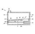
図2および図3は、本実施形態に係るフィルターユニット30の具体的な構成を示す図である。図2は、フィルターFに交差(直交)する平面で切断した断面図である。図3は、図2に示すIII-III断面図である。本実施形態のフィルターユニット30は、水平方向に対して傾斜して配置される。水平方向に対する傾斜角θは、0度から90度のうち任意であるが、本実施形態では傾斜角が60度の場合を例示する。図2では、フィルターユニット30の傾斜方向(水平面に対して傾斜角θが60度の方向)をW1とし、W1-Y平面に直交する方向をW2とする。
2 and 3 are diagrams showing a specific configuration of the
図2に示すように、フィルターユニット30は、インクの流路に連通するフィルター室31を備える。フィルター室31とフィルターFは、W1方向に延びるように配置される。フィルターFは、上流側室S1と下流側室S2とにフィルター室31を隔てるように、フィルター室31内に配置される。上流側室S1は、フィルターFよりも上流側の空間であり、上流側室S1には液体容器14からのインクが流入口DIを介して供給される。下流側室S2は、フィルターFよりも下流側の空間であり、下流側室S2は流出口DOを介して液体吐出部22に連通している。液体容器14からのインクは、流入口DIから上流側室S1に供給され、フィルターFを通過して下流側室S2に移動し、流出口DOから排出されて液体吐出部22に供給される。
As shown in FIG. 2, the
本実施形態の上流側室S1には、フィルターFに対面する壁面41を有し、インクが供給される第1室S11(気泡室)とフィルターFに面する第2室S12とに上流室側室を隔てる隔壁部40が設けられる。本実施形態の隔壁部40は、板状部材36で構成し、板状部材36は上流側基板32と下流側基板34との間に積層される。上流側基板32は、上流側室S1が形成される基板である。下流側基板34は、フィルターFを固定する基板であり、第2室S12および下流側室S2が形成される。
The upstream concubine S1 of the present embodiment has a
隔壁部40における上方(鉛直上方)の部分に、第1室S11と第2室S12とを連通する開口部42を備える。図3に示すように、本実施形態の開口部42は、隔壁部40のW1方向の上方に設けられ、Y方向に延在する。隔壁部40の開口部42は、フィルターFの上端F1を通る仮想水平面G-Gよりも上方にある。本実施形態においてフィルターFの上端F1とは、フィルターFの有効面積の範囲内における上端である。例えば図2に示すフィルターFでは、第2室S12と下流側室S2とに挟まれる範囲がフィルターFの有効面積の範囲であり、そのフィルターFの有効面積の範囲のうちの上端部分がフィルターFの上端F1となる。図2のように、フィルターFの端部(縁部)が下流側基板34に入り込んで溶着または接着により接合される場合には、その接合部分(下流側基板34内に入り込んでいる部分)はフィルターFの有効面積の範囲に含まれない。
An
図2および図3に示すように、隔壁部40は、第1室S11と第2室S12とを連通する複数の連通孔44を備える。ただし、連通孔44は1つであってもよい。各連通孔44は、開口部42よりも下方にあり、開口部42よりも開口面積が小さい。本実施形態の各連通孔44は、フィルターFの上端F1を通る仮想水平面G-Gよりも下方にある。なお、連通孔44は必ずしも設けられていなくてもよい。
As shown in FIGS. 2 and 3, the
本実施形態のフィルターユニット30では、このような隔壁部40を設けることで、第1室S11内に混入した気泡が成長しても、隔壁部40によって気泡の第2室S12への移動が規制されるので、気泡のフィルターFへの接触を避けることができる。
In the
このような構成のフィルターユニット30の作用効果を、隔壁部40を備えない比較例に係るフィルターユニット30’と比較しながら具体的に説明する。図4は、比較例に係るフィルターユニット30’の構成を示す断面図である。図5および図6は、隔壁部40を備える本実施形態のフィルターユニット30の作用説明図である。図5は、印刷時の作用説明図であり、図6は、インクの初期充填時の作用説明図である。
The operation and effect of the
図4に示す比較例のフィルターユニット30’は、フィルターFで上流側室S1と下流側室S2を隔てる構成である。フィルターユニット30’は、上流側室S1に隔壁部40を備えていないので、図4に示すように印刷時に上流側室S1に混入した気泡Buが成長すると、その気泡BuがフィルターFに接触してフィルターFの表面を塞いでしまう。したがって、フィルターFの有効面積が低下し、液体吐出部22へのインクの供給を阻害する。
The filter unit 30'of the comparative example shown in FIG. 4 has a configuration in which the upstream side chamber S1 and the downstream side chamber S2 are separated by a filter F. Since the filter unit 30'does not have the
図4の構成でも、上流側室S1の容積を大きくすれば、フィルターFへの接触を減らしながら、大きな気泡Buを溜めておくことができるとも考えられる。ところが、図4の構成では、上流側室S1の容積を大きくするほど、気泡Buを排出する際にフィルターFの下流側に気泡Buを押し流すために多くのインクの流れが必要になり、気泡Buの排出性が低下してしまう。 Even in the configuration of FIG. 4, it is considered that if the volume of the upstream concubine S1 is increased, large bubbles Bu can be stored while reducing the contact with the filter F. However, in the configuration of FIG. 4, as the volume of the upstream side chamber S1 is increased, a larger amount of ink flow is required to flush the bubble Bu to the downstream side of the filter F when the bubble Bu is discharged, and the bubble Bu becomes larger. Dischargeability is reduced.
これに対して、図5に示す本実施形態のフィルターユニット30では、上流側室S1を第1室S11と第2室S12に隔てる隔壁部40を備えるので、印刷時に第1室S11に混入した気泡Buが成長しても、隔壁部40によって気泡Buの第2室S12への移動が規制されるから、気泡BuのフィルターFへの接触を避けることができる。したがって、気泡BuでフィルターFが塞がれることを抑制できるので、気泡BuによってフィルターFの有効面積が低下することを抑制できる。
On the other hand, in the
このような気泡Buは浮力で上方に移動するから、第1室S11の上方で気泡Buが成長し易い。この点、本実施形態のフィルターユニット30では、隔壁部40における上方の部分に、第1室S11と第2室S12とを連通する開口部42を備えるから、クリーニング時に流出口DOからの吸引により気泡Buを排出する際には、第1室S11の上方に溜まった気泡Buが開口部42を介して第2室S12へ移動し易い。したがって、気泡Buの排出性も向上できる。このように本実施形態によれば、フィルター室31に混入した気泡BuでフィルターFが塞がれることを抑制しながら、気泡排出性も向上できる。なお、クリーニング時には、例えばフィルターユニット30よりも上流のインクの流路に設けたチョーク弁を閉じて、フィルターユニット30へのインクの供給を止めた状態で、上流側室S1の気泡Buを下流側室S2から吸引してフィルターFを通過させることで、下流側室S2から気泡を排出する。
Since such bubble Bu moves upward by buoyancy, bubble Bu tends to grow above the first chamber S11. In this respect, since the
さらに、本実施形態の隔壁部40には、フィルターFの上端F1を通る仮想水平面G-Gよりも上方に開口部42があるから、第1室S11において仮想水平面G-Gよりも上方に溜まった気泡Buが開口部42付近まで成長しても、それよりも下方にフィルターFがあるので、フィルターFに気泡Buが接触することを抑制できる。また、本実施形態の隔壁部40は、開口部42よりも下方に、第1室S11と第2室S12とを連通する複数の連通孔44を備える。したがって、図5に示すように第1室S11の気泡Buが開口部42を塞ぐほど成長してしまったとしても、第1室S11に供給されたインクは、図5の矢印のように連通孔44を通って第2室S12に移動できるから、インクを液体吐出部22に供給できる。また、連通孔44は、開口部42よりも開口面積が小さいから、第1室S11で成長した気泡Buが連通孔44を通過できず、第2室S12に移動することを抑制できる。
Further, since the
また、本実施形態の各連通孔44は、フィルターFの上端F1を通る仮想水平面G-Gよりも下方にあるので、第1室S11において仮想水平面G-Gよりも上方で気泡Buが成長したとしても、それよりも下方に連通孔44があるので、その気泡Buは連通孔44を通過できないから、フィルターFに気泡Buが接触することを抑制できる。また、複数の連通孔44のうちの少なくとも1つは、隔壁部40の鉛直方向の中心位置Oよりも下方に配置される。図5では、すべての連通孔44を中心位置Oよりも下方に配置した場合を例示する。本実施形態の隔壁部40の鉛直方向の中心位置Oは、隔壁部40を構成する板状部材36の中心である。この構成によれば、第1室S11において隔壁部40の鉛直方向の中心位置Oよりも下方において連通孔44を通るインクの流れが生じるため、第1室S11の鉛直方向の下方にインクの淀みが発生することを抑制できる。
Further, since each
なお、大きな気泡Buを孔から排出するために必要な圧力Pd(第1室S11と第2室S12との圧力差)は、下記数式(1)で表すことができる。 The pressure Pd (pressure difference between the first chamber S11 and the second chamber S12) required for discharging the large bubble Bu from the hole can be expressed by the following mathematical formula (1).
Pd=(4γ・COSθd)/D・・・(1) Pd = (4γ · COSθd) / D ... (1)
上記数式(1)において、γは、インクの表面張力であり、θdは、インクの接触角であり、孔が開口する方向W2とγの方向とがなす角度である。Dは孔径である。したがって、開口部42から大きな気泡Buを排出する場合には、第1室S11と第2室S12との圧力差が数式(1)の圧力Pd以上になるようにすればよい。また、連通孔44から大きな気泡Buが排出されないようにするためには、第1室S11と第2室S12との圧力差が数式(1)の圧力Pdよりも小さくなるようにすればよい。
In the above mathematical formula (1), γ is the surface tension of the ink, θd is the contact angle of the ink, and is the angle formed by the direction W2 at which the holes are opened and the direction of γ. D is the hole diameter. Therefore, when discharging a large bubble Bu from the
図6に示すように、液体吐出ヘッド20に最初にインクを充填する初期充填時には、第1室S11の気泡Buが小さく砕けることが多い。この場合、小さい気泡Buは、浮力で第1室S11の上方に溜まるため、時間の経過により小さな気泡Buが結合して大きな気泡Buに成長する。また、図6の点線矢印に示すように、小さい気泡Buが連通孔44を通り抜けて第2室S12に移動してしまったとしても、小さい気泡Buは浮力によって第2室S12内を上昇し、開口部42を通って第1室S11に戻る。したがって、連通孔44を通り抜けた気泡BuでフィルターFが塞がれることを抑制できる。
As shown in FIG. 6, at the time of initial filling in which the
このような本実施形態の隔壁部40は、板状部材36で構成され、フィルターFを固定する下流側基板34に積層されるので、隔壁部40の壁面41とフィルターFとの距離を、下流側基板34の厚みで調整できる。なお、板状部材36を下流側基板34上に直接的に積層してもよいし、板状部材36を下流側基板34に積層したスペーサー上に積層して、板状部材36を下流側基板34上に間接的に積層してもよい。したがって、隔壁部40の壁面41とフィルターFとの間の第2室S12の容積を調整し易い。
Since the
また、本実施形態では、図5のMに示すように第1室S11の一部が鉛直方向においてフィルターFと重なるから、鉛直方向に交差する方向にフィルターユニット30を小型化できる。また、第1室S11はフィルターFよりも上方(仮想水平面G-Gよりも上方)に延在するから、フィルターFよりも上方で第1室S11の容積を拡大できる。したがって、第1室S11に溜められる気泡Buの量を増やすことができる。
Further, in the present embodiment, as shown in M of FIG. 5, a part of the first chamber S11 overlaps with the filter F in the vertical direction, so that the
なお、本実施形態の隔壁部40のうち開口部42の下縁部には、少なくとも鉛直方向に突出する複数のリブを備えるようにしてもよい。図7および図8は、第1実施形態の第1変形例に係るフィルターユニット30の構成を示す図であり、複数のリブ46を備えた隔壁部40の具体例である。図7は、第1変形例に係るフィルターユニット30の断面図であり、図5に対応する。図8は、図7に示すVIII-VIII断面図である。図7および図8の隔壁部40の開口部42の下縁部422には、複数のリブ46が設けられている。各リブ46は、鉛直方向に交差する方向(Y方向)に離間して配列される。
The lower edge of the
このような構成によれば、図8に示すように第1室S11において気泡Buが開口部42まで成長しても、気泡Buがリブ46の上端462で上方に押しつけられるから、第1室S11に供給されるインクはリブ46とリブ46の間の隙間から第2室S12へ移動できるので、インクを液体吐出部22に供給できる。
According to such a configuration, even if the bubble Bu grows up to the
図9および図10は、第1実施形態の第2変形例に係るフィルターユニット30の構成を示す図であり、複数のリブ46を備えた隔壁部40の別の具体例である。図9は、第2変形例に係るフィルターユニット30の断面図であり、図7に対応する。図10は、図9に示すX-X断面図である。図9の開口部42の下縁部422の厚み(W2方向の厚み)は、図7の隔壁部40の下縁部422の厚み(W2方向の厚み)よりも厚い。したがって、図9の構成では、隔壁部40の厚み方向に図7よりも長いリブ46を設けることができる。
9 and 10 are views showing the configuration of the
このような構成によれば、第1室S11において気泡Buを上方に押しつける複数のリブ46の上端462の合計面積を増やすことができる。また、図9のように、隔壁部40の下縁部422を、仮想水平面G-Gに沿うように傾斜させることで、リブ46を仮想水平面G-Gに沿うように配置できる。これによれば、仮想水平面G-Gまで成長した気泡Buを鉛直方向に抑える効果を高めることができる。
According to such a configuration, the total area of the upper end 462s of the plurality of
また、第1室S11から第2室S12へインクを移動させるリブ46とリブ46の間の隙間を、隔壁部40の厚み方向に長くすることができる。また、図9の構成では、W2方向の負側の下端402から仮想水平面G-Gまでの隔壁部40の厚みは、図7の隔壁部40よりも厚い。したがって、第1室S11のうち仮想水平面G-Gよりも上方の容積を、仮想水平面G-Gよりも下方の容積よりも大きくすることができるので、流入口DIから流入した気泡Buが仮想水平面G-Gよりも上方に誘導され易くなる。なお、図7乃至図10のリブ46は、隔壁部40とは別体で設けた場合を例示したが、これに限られず、リブ46を隔壁部40と一体で構成してもよい。
Further, the gap between the
上述した本実施形態では、隔壁部40のうちフィルターFに対面する壁面41が、フィルターFの表面に平行になるように配置した場合を例示したが、これに限られず、フィルターFの表面に対して隔壁部40の壁面41が傾斜していてもよい。図11および図12は、第1実施形態の第3変形例に係るフィルターユニット30の構成を示す図である。図11は、第3変形例に係るフィルターユニット30の断面図であり、図5に対応する。図12は、図11のフィルターユニット30を水平に配置した状態を示す断面図である。図11の隔壁部40は、フィルターFに対面する壁面41とフィルターFとの間が開口部42に向けて広がるように、壁面41がフィルターFに対して傾斜する。
In the present embodiment described above, the case where the
この構成によれば、図12に示すように、検査時などにおいてフィルターFが水平になるようにフィルターユニット30を傾けることで、第2室S12に入り込んだ気泡Buを浮力によって隔壁部40の壁面41に沿って開口部42に導くことができるので、第2室S12の気泡Buを開口部42から第1室S11に容易に移動させることができる。
According to this configuration, as shown in FIG. 12, by tilting the
<第2実施形態>
本発明の第2実施形態について説明する。以下に例示する各形態において作用や機能が第1実施形態と同様である要素については、第1実施形態の説明で使用した符号を流用して各々の詳細な説明を適宜に省略する。第2実施形態では、第1実施形態よりもフィルターFの有効面積を大きくした場合を例示する。
<Second Embodiment>
A second embodiment of the present invention will be described. For the elements whose actions and functions are the same as those of the first embodiment in each of the embodiments exemplified below, the reference numerals used in the description of the first embodiment will be diverted and detailed description of each will be omitted as appropriate. In the second embodiment, a case where the effective area of the filter F is larger than that in the first embodiment is illustrated.
図13は、第2実施形態に係るフィルターユニット30の構成を示す断面図であり、図2に対応する。図14および図15は、第2実施形態に係るフィルターユニット30の作用説明図である。図14は、インク排出時の作用説明図であり、図15は、インク再充填時の作用説明図である。第1実施形態では、フィルターFのW1方向の有効面積の大きさが第1室S11のW1方向の大きさよりも小さいが、第2実施形態では、フィルターFのW1方向の有効面積の大きさが第1室S11のW1方向の大きさよりも大きい。具体的には図13のフィルターユニット30は、第1室S11に対して第2室S12をW1方向の負側にずらし、第2室S12および下流側室S2をW1方向の負側に延出する。
FIG. 13 is a cross-sectional view showing the configuration of the
この構成によれば、フィルターFの有効面積を増やすことができると共に、第1室S11のうちフィルターFの上端F1を通る仮想水平面G-Gよりも上方の部分の容積を大きくとりながら、第2室S12のうち仮想水平面G-Gよりも下方の部分の容積を小さくすることができる。この構成によれば、図15の点線で示す仮想水平面G-Gよりも上方の部分の容積のうち第1室S11の容積(第1室S11のうち仮想水平面G-Gよりも上方の部分の容積)を、図14の点線で示す上流側室S1全体の容積の50%以上にすることができる。 According to this configuration, the effective area of the filter F can be increased, and the volume of the portion of the first chamber S11 above the virtual horizontal plane GG passing through the upper end F1 of the filter F can be increased, while the second chamber S11 has a second volume. The volume of the portion of the chamber S12 below the virtual horizontal plane GG can be reduced. According to this configuration, the volume of the first chamber S11 among the volumes of the portion above the virtual horizontal plane GG shown by the dotted line in FIG. 15 (the portion of the first chamber S11 above the virtual horizontal plane GG). The volume) can be 50% or more of the total volume of the upstream concubine S1 shown by the dotted line in FIG.
インクを再充填する場合には、先ずフィルターユニット30よりも上流のインクの流路に設けられたチョーク弁を閉じてインクの供給を止めてから下流側室S2から吸引することで、フィルターユニット30内を減圧する。この減圧に伴ってフィルターユニット30の第1室S11内の空気(気泡)は膨張する。膨張した空気の一部は、仮想水平面G-Gを超えて第2室S12内のインクを置換すると共に、フィルターFよりも下流側へ排出される。その後、チョーク弁を開いてインクを供給し、図15に示すようにフィルターユニット30内にインクを充填する。
When refilling the ink, first, the choke valve provided in the flow path of the ink upstream of the
このとき、図14に点線で示す上流側室S1内において置換された空気は、再びインクを充填にすることで収縮して気泡になる。本実施形態のように、第1室S11のうち仮想水平面G-Gよりも上方の部分の容積を、上流側室S1の容積の50%以上にすることで、収縮した気泡のほとんどを、上流側室S1のうち図15に点線で示す仮想水平面G-Gよりも上方の部分内に収めることができる。したがって、インクの再充填時に、上流側室S1のうち仮想水平面G-Gよりも上方の部分に気泡が残留していても、フィルターFが仮想水平面G-Gよりも下方に配置されるから、その気泡でフィルターFが塞がれることなく、インクを液体吐出部22に供給できる。
At this time, the replaced air in the upstream concubine S1 shown by the dotted line in FIG. 14 shrinks to become bubbles by refilling the ink. As in the present embodiment, by setting the volume of the portion of the first chamber S11 above the virtual horizontal plane GG to 50% or more of the volume of the upstream side chamber S1, most of the contracted air bubbles are removed from the upstream side chamber. It can be accommodated in the portion of S1 above the virtual horizontal plane GG shown by the dotted line in FIG. Therefore, even if air bubbles remain in the portion of the upstream concubine S1 above the virtual horizontal plane GG at the time of refilling the ink, the filter F is arranged below the virtual horizontal plane GG. Ink can be supplied to the
図13の構成でも、図5および図6の場合と同様に、開口部42と連通孔44を備える隔壁部40によって、気泡の第2室S12への移動が規制されるので、気泡のフィルターFへの接触を避けることができ、気泡の排出性も向上できる。また、図13の構成でも、図13のMに示すように第1室S11の一部が鉛直方向においてフィルターFと重なるから、鉛直方向に交差する方向にフィルターユニット30を小型化できる。また、第1室S11はフィルターFよりも上方(仮想水平面G-Gよりも上方)に延在するから、フィルターFよりも上方で第1室S11の容積を拡大できる。したがって、第1室S11に溜められる気泡Buの量を増やすことができる。
Also in the configuration of FIG. 13, as in the case of FIGS. 5 and 6, the
なお、図13の構成では、第1室S11に対して第2室S12をW1方向の負側にずらすので、第2室S12および下流側室S2側のフィルターFよりも鉛直方向の上方のW1方向の位置が空きスペースになる。そこで、図13の構成では、フィルターFよりも鉛直方向の上方において、フィルターFの面内を含む平面に交差するように、W2方向に第1室S11を延在させることもできる。例えば図16に示す第2実施形態の第1変形例のフィルターユニット30では、W2方向に第1室S11を延在した場合である。図16の構成では、図13の構成に比較してフィルターFよりも鉛直方向の上方のQ部分(図16の点線部分)だけ第1室S11の容積を拡張できる。また、図13および図16では、図2のように隔壁部40を構成する板状部材36と上流側基板32と下流側室S2とを別々に構成するのではなく、これらを一体で構成した場合を例示するが、これらを別体で構成して積層してもよい。
In the configuration of FIG. 13, since the second chamber S12 is shifted to the negative side in the W1 direction with respect to the first chamber S11, the W1 direction is vertically above the filter F on the second chamber S12 and the downstream side chamber S2 side. The position of is an empty space. Therefore, in the configuration of FIG. 13, the first chamber S11 can be extended in the W2 direction so as to intersect the plane including the in-plane of the filter F above the filter F in the vertical direction. For example, in the
また、図13に示すフィルターユニット30を複数組合せるようにしてもよい。例えば図17に示す第2実施形態の第2変形例では、図13に示すフィルターユニット30をW1方向に2つ並べて構成したものである。この場合、図13のままの構成でW1方向に並べただけでは、一方のフィルターユニット30と他方のフィルターユニット30の流入口DIとの間の距離が遠くなる。そこで、図17の構成では、一方の流入口DI(W1方向の正側のフィルターユニット30の流入口)を、他方の流入口DI(W1方向の負側のフィルターユニットの流入口)側に延長する延長流路DISを備える。この構成によれば、図17に示すように、各流入口DIの間の距離Tを短くすることができるので、例えば各流入口DIよりも上流側の部品(各流入口DIに接続する部品)を小型化できる。
Further, a plurality of
なお、上記実施形態では、水平方向に対して60度に傾斜して配置したフィルターユニット30を例示したが、フィルターユニット30の水平方向に対する傾斜角θは、0<θ<90の範囲であることが好ましい。ただし、フィルターユニット30の傾斜角θは、0度(水平配置)であってもよく、90度(鉛直配置)であってもよい。
In the above embodiment, the
<変形例>
以上に例示した態様および実施形態は多様に変形され得る。具体的な変形の態様を以下に例示する。以下の例示や上述の態様から任意に選択された2以上の態様は、相互に矛盾しない範囲で適宜に併合され得る。
<Modification example>
The embodiments and embodiments exemplified above can be variously modified. Specific modes of modification are illustrated below. Two or more embodiments arbitrarily selected from the following examples and the above embodiments may be appropriately merged to the extent that they do not contradict each other.
(1)上述した実施形態では、液体吐出ヘッド20を搭載したキャリッジ18をX方向に沿って反復的に往復させるシリアルヘッドを例示したが、液体吐出ヘッド20を媒体11の全幅にわたり配列したラインヘッドにも本発明を適用可能である。
(1) In the above-described embodiment, the serial head in which the
(2)上述した実施形態では、圧力室に機械的な振動を付与する圧電素子を利用した圧電方式の液体吐出ヘッド20を例示したが、加熱により圧力室の内部に気泡を発生させる発熱素子を利用した熱方式の液体吐出ヘッドを採用することも可能である。
(2) In the above-described embodiment, the piezoelectric
(3)上述した実施形態で例示した液体吐出装置10は、印刷に専用される機器のほか、ファクシミリ装置やコピー機等の各種の機器に採用され得る。もっとも、本発明の液体吐出装置10の用途は印刷に限定されない。例えば、色材の溶液を吐出する液体吐出装置は、液晶表示装置のカラーフィルターや有機EL(Electro Luminescence)ディスプレイ、FED(面発光ディスプレイ)等を形成する製造装置として利用される。また、導電材料の溶液を吐出する液体吐出装置は、配線基板の配線や電極を形成する製造装置として利用される。また、液体の一種として生体有機物の溶液を吐出するチップ製造装置としても利用される。
(3) The
10…液体吐出装置、11…媒体、12…制御装置、14…液体容器、15…搬送機構、18…キャリッジ、20…液体吐出ヘッド、21…吐出面、22…液体吐出部、30…フィルターユニット、30’…フィルターユニット、31…フィルター室、32…上流側基板、34…下流側基板、36…板状部材、40…隔壁部、402…下端、41…壁面、42…開口部、422…下縁部、44…連通孔、46…リブ、462…上端、Bu…気泡、DI…流入口、DIS…延長流路、DO…流出口、F…フィルター、F1…フィルターの上端、G-G…仮想水平面、N…ノズル、O…中心位置、P…ポンプ、Pd…圧力、S1…上流側室、S11…第1室、S12…第2室、S2…下流側室、T…距離、θ…傾斜角。
10 ... Liquid discharge device, 11 ... Medium, 12 ... Control device, 14 ... Liquid container, 15 ... Transfer mechanism, 18 ... Carriage, 20 ... Liquid discharge head, 21 ... Discharge surface, 22 ... Liquid discharge unit, 30 ... Filter unit , 30'... filter unit, 31 ... filter chamber, 32 ... upstream board, 34 ... downstream board, 36 ... plate-like member, 40 ... partition, 402 ... bottom, 41 ... wall surface, 42 ... opening, 422 ... Lower edge, 44 ... communication hole, 46 ... rib, 462 ... upper end, Bu ... bubble, DI ... inlet, DIS ... extension flow path, DO ... outlet, F ... filter, F1 ... upper end of filter, GG ... Virtual horizontal plane, N ... Nozzle, O ... Center position, P ... Pump, Pd ... Pressure, S1 ... Upstream side chamber, S11 ... First chamber, S12 ... Second chamber, S2 ... Downstream side chamber, T ... Distance, θ ... Inclinement Corner.
Claims (17)
水平方向に対して傾斜して前記フィルター室内に配置され、前記液体が供給される上流側室と前記液体吐出部に連通する下流側室とに前記フィルター室を隔てるフィルターと、
前記フィルターに対面する壁面を有し、前記液体が供給される第1室と前記フィルターに面する第2室とに前記上流側室を隔てる隔壁部と、を具備し、
前記隔壁部における上方の部分に、前記第1室と前記第2室とを連通する開口部を備え、
前記フィルターの上端を通る仮想水平面よりも上方に前記隔壁部の開口部がある
フィルターユニット。 A filter chamber located in the middle of the flow path for supplying liquid to the liquid discharge part,
A filter that is arranged in the filter chamber at an angle with respect to the horizontal direction and separates the filter chamber from the upstream side chamber to which the liquid is supplied and the downstream side chamber that communicates with the liquid discharge portion.
It has a wall surface facing the filter, and is provided with a partition wall portion that separates the upstream side chamber from the first chamber to which the liquid is supplied and the second chamber facing the filter.
An opening for communicating the first chamber and the second chamber is provided in the upper portion of the partition wall portion.
The opening of the partition wall is above the virtual horizontal plane passing through the upper end of the filter.
Filter unit.
前記連通孔は、前記開口部よりも下方にあり、前記開口部よりも開口面積が小さい
請求項1に記載のフィルターユニット。 The partition wall portion includes a communication hole that communicates the first chamber and the second chamber.
The communication hole is below the opening and has a smaller opening area than the opening.
The filter unit according to claim 1 .
水平方向に対して傾斜して前記フィルター室内に配置され、前記液体が供給される上流側室と前記液体吐出部に連通する下流側室とに前記フィルター室を隔てるフィルターと、
前記フィルターに対面する壁面を有し、前記液体が供給される第1室と前記フィルターに面する第2室とに前記上流側室を隔てる隔壁部と、を具備し、
前記隔壁部における上方の部分に、前記第1室と前記第2室とを連通する開口部を備え、
前記隔壁部は、前記第1室と第2室とを連通する連通孔を備え、
前記連通孔は、前記開口部よりも下方にあり、前記開口部よりも開口面積が小さい
フィルターユニット。 A filter chamber located in the middle of the flow path for supplying liquid to the liquid discharge part,
A filter that is arranged in the filter chamber at an angle with respect to the horizontal direction and separates the filter chamber from the upstream side chamber to which the liquid is supplied and the downstream side chamber that communicates with the liquid discharge portion.
It has a wall surface facing the filter, and is provided with a partition wall portion that separates the upstream side chamber from the first chamber to which the liquid is supplied and the second chamber facing the filter.
An opening for communicating the first chamber and the second chamber is provided in the upper portion of the partition wall portion.
The partition wall portion includes a communication hole that communicates the first chamber and the second chamber.
The communication hole is below the opening and has a smaller opening area than the opening.
Filter unit .
請求項2または請求項3に記載のフィルターユニット。 The communication hole is below the virtual horizontal plane passing through the upper end of the filter.
The filter unit according to claim 2 or 3 .
前記連通孔のうちの少なくとも1つは、前記隔壁部の鉛直方向の中心位置よりも下方にある
請求項2から請求項4の何れかに記載のフィルターユニット。 The communication holes are plural, and there are a plurality of communication holes.
At least one of the communication holes is below the vertical center position of the partition wall.
The filter unit according to any one of claims 2 to 4 .
前記複数のリブは、鉛直方向に交差する方向に互いに離間して配列される
請求項1から請求項5の何れかに記載のフィルターユニット。 The lower edge of the opening of the partition wall is provided with a plurality of ribs protruding at least in the vertical direction.
The filter unit according to any one of claims 1 to 5, wherein the plurality of ribs are arranged apart from each other in a direction intersecting in the vertical direction.
水平方向に対して傾斜して前記フィルター室内に配置され、前記液体が供給される上流側室と前記液体吐出部に連通する下流側室とに前記フィルター室を隔てるフィルターと、
前記フィルターに対面する壁面を有し、前記液体が供給される第1室と前記フィルターに面する第2室とに前記上流側室を隔てる隔壁部と、を具備し、
前記隔壁部における上方の部分に、前記第1室と前記第2室とを連通する開口部を備え、
前記隔壁部のうち前記開口部の下縁部に、少なくとも鉛直方向に突出する複数のリブを備え、
前記複数のリブは、鉛直方向に交差する方向に互いに離間して配列される
フィルターユニット。 A filter chamber located in the middle of the flow path for supplying liquid to the liquid discharge part,
A filter that is arranged in the filter chamber at an angle with respect to the horizontal direction and separates the filter chamber from the upstream side chamber to which the liquid is supplied and the downstream side chamber that communicates with the liquid discharge portion.
It has a wall surface facing the filter, and is provided with a partition wall portion that separates the upstream side chamber from the first chamber to which the liquid is supplied and the second chamber facing the filter.
An opening for communicating the first chamber and the second chamber is provided in the upper portion of the partition wall portion.
The lower edge of the opening of the partition wall is provided with a plurality of ribs protruding at least in the vertical direction.
The plurality of ribs are arranged so as to be separated from each other in a direction in which they intersect in the vertical direction.
Filter unit .
請求項1から請求項7の何れかに記載のフィルターユニット。 The volume of the portion of the volume of the first chamber above the virtual horizontal plane passing through the upper end of the filter is 50% or more of the volume of the entire upstream concubine.
The filter unit according to any one of claims 1 to 7 .
水平方向に対して傾斜して前記フィルター室内に配置され、前記液体が供給される上流側室と前記液体吐出部に連通する下流側室とに前記フィルター室を隔てるフィルターと、
前記フィルターに対面する壁面を有し、前記液体が供給される第1室と前記フィルターに面する第2室とに前記上流側室を隔てる隔壁部と、を具備し、
前記隔壁部における上方の部分に、前記第1室と前記第2室とを連通する開口部を備え、
前記第1室の容積のうち前記フィルターの上端を通る仮想水平面よりも上方の部分の容積は、前記上流側室全体の容積の50%以上である
フィルターユニット。 A filter chamber located in the middle of the flow path for supplying liquid to the liquid discharge part,
A filter that is arranged in the filter chamber at an angle with respect to the horizontal direction and separates the filter chamber from the upstream side chamber to which the liquid is supplied and the downstream side chamber that communicates with the liquid discharge portion.
It has a wall surface facing the filter, and is provided with a partition wall portion that separates the upstream side chamber from the first chamber to which the liquid is supplied and the second chamber facing the filter.
An opening for communicating the first chamber and the second chamber is provided in the upper portion of the partition wall portion.
The volume of the portion of the volume of the first chamber above the virtual horizontal plane passing through the upper end of the filter is 50% or more of the volume of the entire upstream concubine.
Filter unit .
請求項1から請求項9の何れかに記載のフィルターユニット。 A part of the first chamber overlaps with the filter in the vertical direction.
The filter unit according to any one of claims 1 to 9 .
請求項1から請求項10の何れかに記載のフィルターユニット。 The first chamber extends above the filter.
The filter unit according to any one of claims 1 to 10 .
請求項1から請求項11の何れかに記載のフィルターユニット。
The wall surface is inclined with respect to the filter so that the space between the wall surface facing the filter and the filter in the partition wall portion extends toward the opening.
The filter unit according to any one of claims 1 to 11 .
水平方向に対して傾斜して前記フィルター室内に配置され、前記液体が供給される上流側室と前記液体吐出部に連通する下流側室とに前記フィルター室を隔てるフィルターと、
前記フィルターに対面する壁面を有し、前記液体が供給される第1室と前記フィルターに面する第2室とに前記上流側室を隔てる隔壁部と、を具備し、
前記隔壁部における上方の部分に、前記第1室と前記第2室とを連通する開口部を備え、
前記隔壁部のうち前記フィルターに対面する壁面と前記フィルターとの間が前記開口部に向けて広がるように、前記壁面が前記フィルターに対して傾斜する
フィルターユニット。 A filter chamber located in the middle of the flow path for supplying liquid to the liquid discharge part,
A filter that is arranged in the filter chamber at an angle with respect to the horizontal direction and separates the filter chamber from the upstream side chamber to which the liquid is supplied and the downstream side chamber that communicates with the liquid discharge portion.
It has a wall surface facing the filter, and is provided with a partition wall portion that separates the upstream side chamber from the first chamber to which the liquid is supplied and the second chamber facing the filter.
An opening for communicating the first chamber and the second chamber is provided in the upper portion of the partition wall portion.
The wall surface is inclined with respect to the filter so that the space between the wall surface facing the filter and the filter in the partition wall portion extends toward the opening.
Filter unit .
請求項1から請求項13の何れかに記載のフィルターユニット。 The partition wall portion is a plate-shaped member and is laminated on a substrate for fixing the filter.
The filter unit according to any one of claims 1 to 13 .
水平方向に対して傾斜して前記フィルター室内に配置され、前記液体が供給される上流側室と前記液体吐出部に連通する下流側室とに前記フィルター室を隔てるフィルターと、
前記フィルターに対面する壁面を有し、前記液体が供給される第1室と前記フィルターに面する第2室とに前記上流側室を隔てる隔壁部と、を具備し、
前記隔壁部における上方の部分に、前記第1室と前記第2室とを連通する開口部を備え、
前記隔壁部は、板状部材であり、前記フィルターを固定する基板に積層される
フィルターユニット。 A filter chamber located in the middle of the flow path for supplying liquid to the liquid discharge part,
A filter that is arranged in the filter chamber at an angle with respect to the horizontal direction and separates the filter chamber from the upstream side chamber to which the liquid is supplied and the downstream side chamber that communicates with the liquid discharge portion.
It has a wall surface facing the filter, and is provided with a partition wall portion that separates the upstream side chamber from the first chamber to which the liquid is supplied and the second chamber facing the filter.
An opening for communicating the first chamber and the second chamber is provided in the upper portion of the partition wall portion.
The partition wall portion is a plate-shaped member and is laminated on a substrate for fixing the filter.
Filter unit .
前記フィルターユニットを介して供給された液体を吐出するノズルを備える液体吐出部と、を備える
液体吐出装置。 The filter unit according to claim 1 to 15, and the filter unit according to claim 15 .
A liquid discharge device including a liquid discharge unit including a nozzle for discharging the liquid supplied through the filter unit.
一方の前記流入口を、他方の前記流入口側に延長する延長流路を備える
請求項16に記載の液体吐出装置。
Two of the filter units having an inlet for supplying liquid are arranged side by side.
It is provided with an extension flow path that extends one of the inlets to the other inlet side.
The liquid discharge device according to claim 16 .
Priority Applications (2)
| Application Number | Priority Date | Filing Date | Title |
|---|---|---|---|
| JP2018008095A JP7047397B2 (en) | 2018-01-22 | 2018-01-22 | Liquid discharge device and filter unit |
| US16/252,449 US10703109B2 (en) | 2018-01-22 | 2019-01-18 | Liquid discharge apparatus and filter unit |
Applications Claiming Priority (1)
| Application Number | Priority Date | Filing Date | Title |
|---|---|---|---|
| JP2018008095A JP7047397B2 (en) | 2018-01-22 | 2018-01-22 | Liquid discharge device and filter unit |
Publications (2)
| Publication Number | Publication Date |
|---|---|
| JP2019126915A JP2019126915A (en) | 2019-08-01 |
| JP7047397B2 true JP7047397B2 (en) | 2022-04-05 |
Family
ID=67299151
Family Applications (1)
| Application Number | Title | Priority Date | Filing Date |
|---|---|---|---|
| JP2018008095A Active JP7047397B2 (en) | 2018-01-22 | 2018-01-22 | Liquid discharge device and filter unit |
Country Status (2)
| Country | Link |
|---|---|
| US (1) | US10703109B2 (en) |
| JP (1) | JP7047397B2 (en) |
Families Citing this family (2)
| Publication number | Priority date | Publication date | Assignee | Title |
|---|---|---|---|---|
| KR102239113B1 (en) * | 2019-11-07 | 2021-04-12 | 세메스 주식회사 | ink supply apparatus having bubble blocking part |
| JP2022071489A (en) * | 2020-10-28 | 2022-05-16 | セイコーエプソン株式会社 | Liquid jet device and filling method of liquid jet head |
Citations (5)
| Publication number | Priority date | Publication date | Assignee | Title |
|---|---|---|---|---|
| JP2005103859A (en) | 2003-09-29 | 2005-04-21 | Canon Inc | Ink supply system, recording apparatus, recording head, and liquid supply system |
| JP2007044649A (en) | 2005-08-11 | 2007-02-22 | Canon Inc | Liquid applicator and ink-jet recorder |
| JP2009126044A (en) | 2007-11-22 | 2009-06-11 | Canon Inc | Recording head and recorder |
| US20150239253A1 (en) | 2014-02-25 | 2015-08-27 | Palo Alto Research Center Incorporated | Reservoir having particle trapping features |
| JP2016215420A (en) | 2015-05-15 | 2016-12-22 | セイコーエプソン株式会社 | Liquid injection head, manufacturing method for the sane and liquid injection device |
Family Cites Families (19)
| Publication number | Priority date | Publication date | Assignee | Title |
|---|---|---|---|---|
| US6007191A (en) * | 1993-08-19 | 1999-12-28 | Fuji Xerox Co., Ltd. | Ink supply unit |
| JP3267457B2 (en) * | 1994-11-30 | 2002-03-18 | キヤノン株式会社 | Ink jet device and ink supply device used for the device |
| EP0683050B1 (en) * | 1994-05-20 | 2000-08-02 | Canon Kabushiki Kaisha | Ink supplying apparatus and ink jet recording apparatus having same |
| JPH09277552A (en) | 1996-04-16 | 1997-10-28 | Seiko Epson Corp | Ink jet recording device |
| US6000789A (en) * | 1996-04-23 | 1999-12-14 | Fuji Xerox Co., Ltd. | Printer and ink tank |
| JP3503678B2 (en) * | 1997-06-03 | 2004-03-08 | セイコーエプソン株式会社 | Ink jet recording device |
| JP2000177144A (en) | 1998-12-17 | 2000-06-27 | Seiko Epson Corp | Ink-jet type recording apparatus |
| US6196671B1 (en) * | 1999-12-20 | 2001-03-06 | Xerox Corporation | Ink-jet cartridge for an ink jet printer having air ingestion control |
| ES2306687T3 (en) * | 2000-10-20 | 2008-11-16 | Seiko Epson Corporation | INK CARTRIDGE FOR AN INK RECORDING DEVICE DEVICE. |
| US6508545B2 (en) * | 2000-12-22 | 2003-01-21 | Hewlett-Packard Company | Apparatus for providing ink to an ink jet print head |
| JP2005074836A (en) | 2003-09-01 | 2005-03-24 | Seiko Epson Corp | Inkjet head unit |
| US7111932B2 (en) * | 2003-09-18 | 2006-09-26 | Hewlett-Packard Development Company | Managing contaminants in a fluid-delivery device |
| US7556362B2 (en) * | 2004-02-03 | 2009-07-07 | Seiko Epson Corporation | Pressure control valve unit and liquid ejecting apparatus |
| JP4285540B2 (en) * | 2006-12-28 | 2009-06-24 | ブラザー工業株式会社 | Inkjet head |
| JP5078548B2 (en) * | 2007-10-26 | 2012-11-21 | キヤノン株式会社 | Discharging device and recording device |
| JP2011206959A (en) | 2010-03-29 | 2011-10-20 | Seiko Epson Corp | Self-sealing unit, liquid ejecting head unit, and liquid ejecting apparatus |
| US20110279559A1 (en) * | 2010-05-17 | 2011-11-17 | Silverbrook Research Pty Ltd | Printing system having pressure control at printhead |
| US8439481B2 (en) * | 2010-10-26 | 2013-05-14 | Eastman Kodak Company | Liquid dispenser including sloped outlet opening wall |
| US8807718B2 (en) * | 2012-11-28 | 2014-08-19 | Eastman Kodak Company | Pressure regulated inkjet printhead with replaceable on-axis ink tank |
-
2018
- 2018-01-22 JP JP2018008095A patent/JP7047397B2/en active Active
-
2019
- 2019-01-18 US US16/252,449 patent/US10703109B2/en active Active
Patent Citations (5)
| Publication number | Priority date | Publication date | Assignee | Title |
|---|---|---|---|---|
| JP2005103859A (en) | 2003-09-29 | 2005-04-21 | Canon Inc | Ink supply system, recording apparatus, recording head, and liquid supply system |
| JP2007044649A (en) | 2005-08-11 | 2007-02-22 | Canon Inc | Liquid applicator and ink-jet recorder |
| JP2009126044A (en) | 2007-11-22 | 2009-06-11 | Canon Inc | Recording head and recorder |
| US20150239253A1 (en) | 2014-02-25 | 2015-08-27 | Palo Alto Research Center Incorporated | Reservoir having particle trapping features |
| JP2016215420A (en) | 2015-05-15 | 2016-12-22 | セイコーエプソン株式会社 | Liquid injection head, manufacturing method for the sane and liquid injection device |
Also Published As
| Publication number | Publication date |
|---|---|
| JP2019126915A (en) | 2019-08-01 |
| US20190224981A1 (en) | 2019-07-25 |
| US10703109B2 (en) | 2020-07-07 |
Similar Documents
| Publication | Publication Date | Title |
|---|---|---|
| JP7151372B2 (en) | LIQUID EJECTING HEAD AND LIQUID EJECTING APPARATUS | |
| JP2018103602A (en) | Liquid injection head and liquid injection device | |
| JP5610596B2 (en) | Inkjet print head | |
| JP5882005B2 (en) | Liquid ejecting head and liquid ejecting apparatus | |
| JP6881461B2 (en) | Inkjet head and inkjet recording device | |
| US10155395B2 (en) | Ink circulation device and inkjet recording device | |
| US8246153B2 (en) | Bubble control unit, liquid ejecting head, and liquid ejecting apparatus | |
| JP6992294B2 (en) | Liquid discharge head and filter unit | |
| JP7047397B2 (en) | Liquid discharge device and filter unit | |
| WO2019167385A1 (en) | Liquid discharge head and liquid discharge device | |
| JP2016112888A (en) | Liquid discharge head, liquid discharge unit and device for discharging liquid | |
| US9889657B2 (en) | Liquid ejecting head and liquid ejecting apparatus | |
| JP4561276B2 (en) | Inkjet recording device | |
| JP7205212B2 (en) | Liquid injection device and supply system | |
| JP7139790B2 (en) | LIQUID EJECTING HEAD AND LIQUID EJECTING APPARATUS | |
| JP7055997B2 (en) | How to drive the liquid discharge device and the liquid discharge device | |
| WO2019167386A1 (en) | Liquid discharge head and liquid discharge device | |
| JP5167669B2 (en) | Liquid supply device and liquid discharge device | |
| JP2018024162A (en) | Liquid discharge apparatus and method of maintaining liquid discharge apparatus | |
| JP2017061061A (en) | Liquid jet head and liquid jet device | |
| JP5994234B2 (en) | Liquid ejector | |
| JP2020104493A (en) | Liquid discharge head and liquid discharge device | |
| JP2017124536A (en) | Liquid jet head and liquid jet device | |
| JP2008246861A (en) | Inkjet head |
Legal Events
| Date | Code | Title | Description |
|---|---|---|---|
| A621 | Written request for application examination |
Free format text: JAPANESE INTERMEDIATE CODE: A621 Effective date: 20201116 |
|
| A977 | Report on retrieval |
Free format text: JAPANESE INTERMEDIATE CODE: A971007 Effective date: 20210818 |
|
| A131 | Notification of reasons for refusal |
Free format text: JAPANESE INTERMEDIATE CODE: A131 Effective date: 20210831 |
|
| A521 | Request for written amendment filed |
Free format text: JAPANESE INTERMEDIATE CODE: A523 Effective date: 20211028 |
|
| TRDD | Decision of grant or rejection written | ||
| A01 | Written decision to grant a patent or to grant a registration (utility model) |
Free format text: JAPANESE INTERMEDIATE CODE: A01 Effective date: 20220222 |
|
| A61 | First payment of annual fees (during grant procedure) |
Free format text: JAPANESE INTERMEDIATE CODE: A61 Effective date: 20220307 |
|
| R150 | Certificate of patent or registration of utility model |
Ref document number: 7047397 Country of ref document: JP Free format text: JAPANESE INTERMEDIATE CODE: R150 |