JP7013210B2 - Imaging device, imaging method, display device and display method - Google Patents
Imaging device, imaging method, display device and display method Download PDFInfo
- Publication number
- JP7013210B2 JP7013210B2 JP2017217225A JP2017217225A JP7013210B2 JP 7013210 B2 JP7013210 B2 JP 7013210B2 JP 2017217225 A JP2017217225 A JP 2017217225A JP 2017217225 A JP2017217225 A JP 2017217225A JP 7013210 B2 JP7013210 B2 JP 7013210B2
- Authority
- JP
- Japan
- Prior art keywords
- image
- imaging
- image pickup
- region
- captured
- Prior art date
- Legal status (The legal status is an assumption and is not a legal conclusion. Google has not performed a legal analysis and makes no representation as to the accuracy of the status listed.)
- Active
Links
Images


Classifications
-
- H—ELECTRICITY
- H04—ELECTRIC COMMUNICATION TECHNIQUE
- H04N—PICTORIAL COMMUNICATION, e.g. TELEVISION
- H04N1/00—Scanning, transmission or reproduction of documents or the like, e.g. facsimile transmission; Details thereof
- H04N1/00127—Connection or combination of a still picture apparatus with another apparatus, e.g. for storage, processing or transmission of still picture signals or of information associated with a still picture
- H04N1/00129—Connection or combination of a still picture apparatus with another apparatus, e.g. for storage, processing or transmission of still picture signals or of information associated with a still picture with a display device, e.g. CRT or LCD monitor
-
- H—ELECTRICITY
- H04—ELECTRIC COMMUNICATION TECHNIQUE
- H04N—PICTORIAL COMMUNICATION, e.g. TELEVISION
- H04N23/00—Cameras or camera modules comprising electronic image sensors; Control thereof
- H04N23/60—Control of cameras or camera modules
- H04N23/63—Control of cameras or camera modules by using electronic viewfinders
- H04N23/633—Control of cameras or camera modules by using electronic viewfinders for displaying additional information relating to control or operation of the camera
- H04N23/635—Region indicators; Field of view indicators
-
- H—ELECTRICITY
- H04—ELECTRIC COMMUNICATION TECHNIQUE
- H04N—PICTORIAL COMMUNICATION, e.g. TELEVISION
- H04N23/00—Cameras or camera modules comprising electronic image sensors; Control thereof
- H04N23/45—Cameras or camera modules comprising electronic image sensors; Control thereof for generating image signals from two or more image sensors being of different type or operating in different modes, e.g. with a CMOS sensor for moving images in combination with a charge-coupled device [CCD] for still images
-
- H—ELECTRICITY
- H04—ELECTRIC COMMUNICATION TECHNIQUE
- H04N—PICTORIAL COMMUNICATION, e.g. TELEVISION
- H04N23/00—Cameras or camera modules comprising electronic image sensors; Control thereof
- H04N23/58—Means for changing the camera field of view without moving the camera body, e.g. nutating or panning of optics or image sensors
-
- H—ELECTRICITY
- H04—ELECTRIC COMMUNICATION TECHNIQUE
- H04N—PICTORIAL COMMUNICATION, e.g. TELEVISION
- H04N23/00—Cameras or camera modules comprising electronic image sensors; Control thereof
- H04N23/60—Control of cameras or camera modules
- H04N23/62—Control of parameters via user interfaces
-
- H—ELECTRICITY
- H04—ELECTRIC COMMUNICATION TECHNIQUE
- H04N—PICTORIAL COMMUNICATION, e.g. TELEVISION
- H04N23/00—Cameras or camera modules comprising electronic image sensors; Control thereof
- H04N23/60—Control of cameras or camera modules
- H04N23/63—Control of cameras or camera modules by using electronic viewfinders
- H04N23/631—Graphical user interfaces [GUI] specially adapted for controlling image capture or setting capture parameters
- H04N23/632—Graphical user interfaces [GUI] specially adapted for controlling image capture or setting capture parameters for displaying or modifying preview images prior to image capturing, e.g. variety of image resolutions or capturing parameters
-
- H—ELECTRICITY
- H04—ELECTRIC COMMUNICATION TECHNIQUE
- H04N—PICTORIAL COMMUNICATION, e.g. TELEVISION
- H04N23/00—Cameras or camera modules comprising electronic image sensors; Control thereof
- H04N23/60—Control of cameras or camera modules
- H04N23/66—Remote control of cameras or camera parts, e.g. by remote control devices
- H04N23/661—Transmitting camera control signals through networks, e.g. control via the Internet
-
- H—ELECTRICITY
- H04—ELECTRIC COMMUNICATION TECHNIQUE
- H04N—PICTORIAL COMMUNICATION, e.g. TELEVISION
- H04N23/00—Cameras or camera modules comprising electronic image sensors; Control thereof
- H04N23/60—Control of cameras or camera modules
- H04N23/69—Control of means for changing angle of the field of view, e.g. optical zoom objectives or electronic zooming
-
- H—ELECTRICITY
- H04—ELECTRIC COMMUNICATION TECHNIQUE
- H04N—PICTORIAL COMMUNICATION, e.g. TELEVISION
- H04N23/00—Cameras or camera modules comprising electronic image sensors; Control thereof
- H04N23/60—Control of cameras or camera modules
- H04N23/695—Control of camera direction for changing a field of view, e.g. pan, tilt or based on tracking of objects
-
- H—ELECTRICITY
- H04—ELECTRIC COMMUNICATION TECHNIQUE
- H04N—PICTORIAL COMMUNICATION, e.g. TELEVISION
- H04N23/00—Cameras or camera modules comprising electronic image sensors; Control thereof
- H04N23/60—Control of cameras or camera modules
- H04N23/698—Control of cameras or camera modules for achieving an enlarged field of view, e.g. panoramic image capture
-
- H—ELECTRICITY
- H04—ELECTRIC COMMUNICATION TECHNIQUE
- H04N—PICTORIAL COMMUNICATION, e.g. TELEVISION
- H04N23/00—Cameras or camera modules comprising electronic image sensors; Control thereof
- H04N23/90—Arrangement of cameras or camera modules, e.g. multiple cameras in TV studios or sports stadiums
Landscapes
- Engineering & Computer Science (AREA)
- Multimedia (AREA)
- Signal Processing (AREA)
- Human Computer Interaction (AREA)
- Studio Devices (AREA)
- Stereoscopic And Panoramic Photography (AREA)
- Accessories Of Cameras (AREA)
- Closed-Circuit Television Systems (AREA)
Description
本発明は、撮像装置、撮像方法、表示装置および表示方法に関する。 The present invention relates to an image pickup device, an image pickup method, a display device, and a display method.
従来、ユーザが撮像装置の撮像領域の変更を行う方法の1つとして、撮像装置が過去に撮像した画像を使用する方法が用いられていた。例えば、特許文献1では、過去に撮像した画像を使用して作成したパノラマ画像を表示部に表示し、表示されたパノラマ画像における任意の領域をユーザが選択すると、当該領域に撮像領域を変更する技術が開示されている。特許文献2では、同一カメラで同一領域を撮像する場合、過去の撮像画像からパン角度、チルト角度、ズーム位置等を取得し、過去の撮像画像と同じパン角度等で撮像を行う技術が開示されている。 Conventionally, as one of the methods for a user to change the image pickup area of an image pickup device, a method of using an image captured by the image pickup device in the past has been used. For example, in Patent Document 1, a panoramic image created by using an image captured in the past is displayed on a display unit, and when a user selects an arbitrary area in the displayed panoramic image, the image pickup area is changed to that area. The technology is disclosed. Patent Document 2 discloses a technique of acquiring a pan angle, tilt angle, zoom position, etc. from a past captured image and performing imaging at the same pan angle, etc. as the past captured image when the same area is imaged by the same camera. ing.
特許文献1および特許文献2では過去に撮像した画像を使用するため、負荷や電力削減の観点や、過去のある時点と現時点の同一の撮像領域の状況を比較する用途では有用である。一方で、注視したい対象が動体であるような場合、動体が特定の領域に現れたことを確認した上で撮像領域を変更するために、使用する画像を常に時間的に最新の状態にしておきたいという要望もあるが、特許文献1または2はこのような要望に対応していない。
そこで、本発明の目的は、過去に撮像した領域の現在の状態をユーザが確認できるようにしつつ撮像装置の撮像領域の変更を可能にすることである。
Since the images captured in the past are used in Patent Document 1 and Patent Document 2, it is useful for the viewpoint of load and power reduction and for comparing the situation of the same imaging region at a certain point in the past and the present time. On the other hand, if the object you want to gaze at is a moving object, keep the image used up-to-date in time in order to change the imaging area after confirming that the moving object has appeared in a specific area. Although there is a request, Patent Document 1 or 2 does not correspond to such a request.
Therefore, an object of the present invention is to make it possible to change the image pickup area of the image pickup apparatus while allowing the user to confirm the current state of the area imaged in the past.
上記目的を達成するために、本発明の1つの態様による撮像装置は、第一の撮像領域を撮像する第一の撮像手段と、前記第一の撮像領域内の第二の撮像領域を撮像する第二の撮像手段と、前記第二の撮像手段により撮像した第二の撮像領域に対応する位置情報を保持する保持手段と、前記第一の撮像手段により撮像した撮像画像から、前記保持手段が保持している位置情報に対応する第二の撮像領域の部分画像を出力する出力手段と、前記出力手段が出力した複数の部分画像のうちの1つが選択されると、当該選択された部分画像に対応する第二の撮像領域を撮像するように、前記第二の撮像手段を制御する制御手段と、を備える。 In order to achieve the above object, the image pickup apparatus according to one aspect of the present invention captures a first imaging means for imaging a first imaging region and a second imaging region within the first imaging region. From the second imaging means, the holding means for holding the position information corresponding to the second imaging region captured by the second imaging means, and the captured image captured by the first imaging means , the holding means When one of the output means for outputting the partial image of the second imaging region corresponding to the held position information and the plurality of partial images output by the output means is selected, the selected partial image is selected . A control means for controlling the second image pickup means so as to capture a second image pickup region corresponding to a partial image is provided.
本発明によれば、第一の撮像領域を撮像した画像から第二の撮像領域の画像を切り出して表示するので、第二の撮像領域の状態をユーザが確認できるようにし易くすることができる。 According to the present invention, since the image of the second imaging region is cut out from the image captured by the first imaging region and displayed, it is possible to facilitate the user to confirm the state of the second imaging region.
以下に、本発明の好ましい実施の形態を、添付の図面に基づいて詳細に説明する。なお、以下に説明する実施形態は、本発明の実現手段としての一例であり、本発明が適用される装置やシステムの構成や各種条件によって適宜修正又は変更されるべきものであり、本発明は以下の実施形態に限定されるものではない。 Hereinafter, preferred embodiments of the present invention will be described in detail with reference to the accompanying drawings. It should be noted that the embodiment described below is an example as a means for realizing the present invention, and should be appropriately modified or changed depending on the configuration and various conditions of the apparatus or system to which the present invention is applied. It is not limited to the following embodiments.
第1実施形態
(撮像システム)
図1を参照して本発明の第1実施形態に関わる撮像システム10を説明する。撮像システム10は、撮像装置100と、撮像装置100にIPネットワーク130を介して接続されたUI表示部140とからなる。撮像装置100は、室内の天井または壁に設置されているとする。UI表示部140は、表示装置(クライアント装置)の一例である。
撮像装置100は、広角カメラ110と、PTZカメラ(パンチルトズームカメラ)120と、システム制御部124と、記憶部125とを有する。本実施形態の撮像装置100は、広角カメラ110とPTZカメラ120が一体化した撮像装置である。広角カメラ110とPTZカメラ120は、同一の筐体に収容されている。撮像装置100は、IPネットワーク130を介してUI表示部140に相互通信可能な状態で、無線または有線で接続されている。UIはUser Interfaceの略である。
First Embodiment (imaging system)
The
The
広角カメラ110は、広い画角の画像を取得するために広角レンズ等で構成される撮像光学系111、撮像素子部112および画像処理部113によって構成されている。本実施形態の広角カメラ110は、撮像方向(パン角度、チルト角度)およびズーム位置(画角)を変更する手段を有していない。また、本実施形態の広角カメラ110は、単一のカメラで構成される。広角カメラ110はPTZカメラ120よりも広い画角を持つ。広角カメラ110は、所定の撮像領域を撮像する。
The wide-
PTZカメラ120は、ズームレンズ、フォーカスレンズ、絞り機構などにより構成される撮像光学系121、撮像素子部122、画像処理部123、駆動制御部126、ズームモータ127、パンモータ128およびチルトモータ129によって構成される。PTZカメラ120は、駆動制御部126によって、撮像光学系121を駆動させることでフォーカスや絞りの調整を行うことができる。また、PTZカメラ120は、ズームモータ127、パンモータ128およびチルトモータ129を駆動させることでPTZカメラ120の撮像方向、画角の変更等を行うことができる。つまり、PTZカメラ120は撮像領域を変更することができる。PTZカメラ120は、撮像領域を変更する前のパン角度、チルト角度およびズーム位置(画角)の情報を記憶部125に格納する。PTZカメラ120の画角は広角カメラ110の画角より狭いが、PTZカメラ120は、モータ127、128、129を駆動することで広角カメラ110の全画角の範囲に亘って撮像領域を変更することが可能である。PTZカメラ120は、広角カメラ110が撮像する所定の撮像領域内の撮像領域を撮像する。
The
システム制御部124は、カメラ制御、画像のエンコーディング(符号化)、表示画像の生成、記憶部125に対する記憶処理、ネットワーク配信、広角カメラ110の画像の切り出し(デジタルPTZ)等の処理を行う。システム制御部124によるカメラ制御は、広角カメラ110の制御と、PTZカメラ120の制御とを含む。広角カメラ110の画像の切り出しする場合、UI表示部140に表示される広角カメラ110の撮像画像から任意の領域を指定することで、切り出し処理を行うことができる。システム制御部124は、切出した画像を切出画像として出力する。システム制御部124は、例えば、CPUにより構成される。システム制御部124は、広角カメラ110が撮像した撮像画像をUI表示部140に送信する。
The
記憶部125は、例えば、ROMおよびRAMにより構成される。ROMは、例えば、システム制御部(CPU)124が処理を実行するために必要なプログラム等を記憶する。CPUが、ROMに記憶されたプログラムに基づき処理を実行することにより、撮像装置100の機能や処理(図3)等が実現される。なお、当該プログラム等は、外部メモリや着脱可能な記憶媒体(図示せず)に記憶されてもよい。RAMは、CPUがROMから読み出したプログラムを展開し、処理を実行するためのメモリである。また、RAMは、一時記憶メモリとして各種処理の対象となるデータを一時記憶するための記憶領域としても使用される。
The storage unit 125 is composed of, for example, a ROM and a RAM. The ROM stores, for example, a program or the like necessary for the system control unit (CPU) 124 to execute a process. When the CPU executes the process based on the program stored in the ROM, the functions and processes (FIG. 3) of the
IPネットワーク130は、インターネットプロトコルに基づいてデータの送受信を行う。
UI表示部140は、例えば、パーソナルコンピュータやタブレット端末(またはその表示部)であり、入出力機能や通信機能を有する。UI表示部140は、広角カメラ110およびPTZカメラ120に対して、撮像パラメータの変更や各モータ127~129の制御指示、映像ストリーミング開始等の各種コマンドを送信する。このコマンド送信により、UI表示部140は、広角カメラ110およびPTZカメラ120の制御を行うことができる。撮像装置100は上記したコマンドに対してレスポンスや映像ストリーミングをUI表示部140に送信する。
The
The
図1に示す各機能モジュール(画像処理部113、画像処理部123、システム制御部124、駆動制御部126)はソフトウェア又はハードウェアによって実現される。ソフトウェアによって実現される場合、前述した各機能モジュールの機能を提供するためのプログラムが記憶部125のROMに記憶される。記憶されたプログラムは、適宜、記憶部125のRAMに読み出され、システム制御部124を構成するCPUが実行することにより、それら機能モジュールの機能が実現される。一方、ハードウェアにより実現される場合、例えば、所定のコンパイラを用いることで、各機能モジュールの機能を実現するためのプログラムからFPGA上に自動的に専用回路を生成すればよい。FPGAとは、Field Programmable Gate Arrayの略である。また、FPGAと同様にしてGate Array回路を形成し、ハードウェアとして実現するようにしてもよい。また、ASIC(Application Specific Integrated Circuit)により実現するようにしてもよい。なお、図1に示した機能モジュールの構成は一例であり、複数の機能モジュールが1つの機能モジュールを構成するようにしてもよいし、いずれかの機能モジュールが複数の機能を行うモジュールに分かれてもよい。
Each functional module (
(UI表示部)
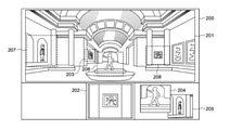
図2は、UI表示部140に表示される画像201、202、204および205を示している。UI表示部140の表示面200はユーザが使用するUIである。UI表示部140は、画像201、202、204および205を表示する表示部を有する。
画像201は、広角カメラ110が撮像している領域のリアルタイムの画像である。画像202は、PTZカメラ120が撮像している領域(撮像領域208)のリアルタイムの画像である。本実施形態では、広角カメラ110の撮像領域とPTZカメラ120のパン角度、チルト角度、ズーム(望遠、広角)位置とは、紐づけられている(対応づけられている、関連づけられている)とする。例えば、ユーザがUI表示部140から画像201内の領域203を指定すると、システム制御部124は、領域203に紐づけられたパン角度、チルト角度、ズーム位置の情報に基づいてPTZカメラ120が領域203を撮像するように各モータ127~129を駆動させる。このモータ駆動により、PTZカメラ120の撮像領域を変更することができる。
(UI display)
FIG. 2 shows
画像204は、PTZカメラ120が現在の1つ前の姿勢で撮像した撮像領域206を広角カメラ110で現在撮像している画像から切り出して表示しているサムネイル画像である。画像205はPTZカメラ120が現在の2つ前の姿勢で撮像した撮像領域207を広角カメラ110で現在撮像している画像から切り出して表示しているサムネイル画像である。サムネイル画像204には、撮像領域206を撮像した際のPTZカメラ120のパン角度、チルト角度、ズーム位置の情報(撮像情報)が紐づけられて記憶部125に格納されている。サムネイル画像205には、撮像領域207を撮像した際のPTZカメラ120のパン角度、チルト角度、ズーム位置の情報が紐づけられて記憶部125に格納されている。撮像領域(撮像範囲)203、206~208は画像201から切り出す領域を示しているので、切出領域と称されることもある。また、サムネイル画像204、205は切出画像である。
The
(PTZカメラの撮像領域の変更)
図3および図4を用いて、過去の撮像領域を撮像するようにPTZカメラ120のパン角度、チルト角度、ズーム位置を変更する場合のフローについて説明する。
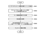
図4(a)に示されるように、システム制御部124(図1)は、まず、ユーザがポインタ401でサムネイル画像205を選択したことを検知する(S301)。その後、システム制御部124は、サムネイル画像205に紐づけられて格納されているPTZカメラ120のパン角度、チルト角度、ズーム位置の情報を記憶部125から読み出す(S302)。システム制御部124は、読み出されたパン角度、チルト角度およびズーム位置の情報に基づいて、PTZカメラ120の駆動制御部126にズームモータ127、パンモータ128およびチルトモータ129を駆動させるように命令を送信する(S303)。つまり、システム制御部124は、領域207をPTZカメラ120が撮像するように、駆動制御部126に各モータ127~129の駆動命令を送信する。
(Change of imaging area of PTZ camera)
A flow in the case of changing the pan angle, tilt angle, and zoom position of the
As shown in FIG. 4A, the system control unit 124 (FIG. 1) first detects that the user has selected the
次に、システム制御部124は、広角カメラ110の画像201上で、選択されたサムネイル画像205の切出領域207を画像選択前にPTZカメラ120が撮像していた領域208に変更する(S304)。続いて、システム制御部124は、撮像領域変更前のPTZカメラ120のパン角度、チルト角度およびズーム位置の情報を画像(図2の画像202)に紐づけて記憶部125に記憶する(S305)。最後に、システム制御部124は、表示しているサムネイル画像の更新を行う(S306)。具体的には、図4(a)の画像202が「1つ前の姿勢で撮像された画像(直近の画像)」になるので、画像202が画像204に更新され、図4(a)の画像204が「2つ前の姿勢で撮像された画像」になるので、画像205に更新される。図4(a)のサムネイル画像205は削除されることになる。この状態が図4(b)に示されている。
Next, the
このようにして、ユーザは広角カメラ110が撮像しているリアルタイムの画像201(図4(a))で現在の状況を確認した上で、PTZカメラ120の撮像領域を過去に設定したことがある撮像領域207に変更することが可能となる。(図4(a)の画像202は、図4(b)では領域207の画像になっている。)
なお、上記の説明では、過去に撮像していた撮像領域のサムネイル画像を表示面200内に2つ表示しているが(サムネイル画像204と205)、本実施形態はこのような表示態様に限定されない。例えば、表示面200には、過去に撮像していた撮像領域のサムネイル画像を1つだけ表示してもよいし、3つ以上表示してもよい。
In this way, the user has set the imaging area of the
In the above description, two thumbnail images of the imaging region previously captured are displayed on the display surface 200 (
また、図4(a)ではサムネイル画像204と205を表示面200に表示する場合、サムネイル画像204がサムネイル画像205より前面に来るように表示している。つまり、図4(a)では、サムネイル画像が複数ある場合、時間的に現在に近いものが前面に来るように表示している。本実施形態はこのような表示形態(表示順序)に限定されない。例えば、複数のサムネイル画像を表示面200に表示する場合の表示順序は、撮像領域として長時間設定していたものを前面に来るように表示してもよい。
Further, in FIG. 4A, when the
(切出画像位置の表示)
1つのサムネイル画像を選択した場合、どの領域を撮像することになるのかを示すために、広角カメラ110の撮像画像201に当該領域の外縁を示す枠線を重畳表示してもよいし、当該サムネイル画像と撮像領域を繋ぐ線を重畳表示してもよい。また、ユーザ操作のポインタ401がサムネイル画像上に合わされた(つまり、1つのサムネイル画像を選択した)際に、撮像画像201に上記枠線や上記繋ぐ線を重畳表示してもよい。枠線や繋ぐ線などの図形・指標を撮像画像201に表示することで、サムネイル画像と撮像領域とが関連づけられ、サムネイル画像と撮像領域との対応の確認が容易になる。
(Display of cutout image position)
When one thumbnail image is selected, a frame line indicating the outer edge of the region may be superimposed and displayed on the captured
(サムネイル画像の更新タイミング)
サムネイル画像の更新はPTZカメラ120に対して所定値以上のパン角度、チルト角度またはズーム位置の変更があった際に行うようにしてもよい。また、連続的なサムネイル画像の更新を許可しない場合は、撮像領域の変更後、所定時間以上ポインタ401によるサムネイル画像選択がされなかった時点で、サムネイル画像の更新するようにしてもよい。あるいは、撮像領域の変更後、所定時間が経過した後に、サムネイル画像の更新を許可するようにしてもよい。これにより、例えば、サムネイル画像が多数ある場合に、撮像領域の微調整による連続的なサムネイル画像の更新を回避することができる。
(Thumbnail image update timing)
The thumbnail image may be updated when the pan angle, tilt angle, or zoom position of the
(画像配信の優先度)
広角カメラ110の画像のIPネットワーク130への配信は切出画像を表示している領域(例えば、図4(a)の領域207)の画像を他の領域の画像よりも優先度を上げて配信するようにしてよい。特に広角カメラ110を複数のカメラで構成する場合には切出画像を表示している領域の画像を優先して配信することで、広角カメラ110の切出画像とPTZカメラ120で撮像される画像とのタイムラグを小さくすることが可能となる。
(Priority of image distribution)
For distribution of the image of the wide-
(第1実施形態の効果)
以上、説明したように、本実施形態によれば、過去に撮像した領域207の現在の状態をリアルタイムの画像201、205によりユーザに表示しつつ、PTZカメラ120の撮像領域を領域208から領域207へ変更できる。
(Effect of the first embodiment)
As described above, according to the present embodiment, the imaging region of the
第2実施形態
次に、本発明の第2実施形態について、図5~図7を用いて説明する。第1実施形態では、PTZカメラ120の撮像領域は、ユーザがポインタ401で選択したサムネイル画像の撮像領域に変更された。第2実施形態では、PTZカメラ120の撮像領域をあらかじめ設定された複数の撮像領域に順次変更する場合を説明する。第2実施形態では、PTZカメラ120の撮像領域が、所定の順序(巡回順序)で変化して行く。このような撮像は、巡回設定撮影と称されることもある。あらかじめ設定された複数の撮像領域は、以下の記載において、プリセット位置と称されることもある。
以下に、第2実施形態における撮像装置101の撮像領域、切り出し範囲の変更方法、ならびにサムネイル画像の表示方法について説明する。なお、第1実施形態と同じ構成については、同じ参照符号を使用し、詳細な説明は省略する。第2実施形態の撮像システム10の構成は、第1実施形態と同一である。以下の記載では、第1実施形態と異なるUI表示部140における表示と、PTZカメラ120の撮像方向および画角の変更(パン角度、チルト角度およびズーム位置の変更)とについて説明する。
Second Embodiment Next, the second embodiment of the present invention will be described with reference to FIGS. 5 to 7. In the first embodiment, the image pickup area of the
Hereinafter, the image pickup area of the image pickup apparatus 101, the method of changing the cutout range, and the method of displaying the thumbnail image in the second embodiment will be described. The same reference numerals are used for the same configuration as that of the first embodiment, and detailed description thereof will be omitted. The configuration of the
(UI表示部)
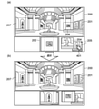
図5を用いてUI表示部140の画像の表示について説明する。画像501、502、503および504は、PTZカメラ120の巡回設定撮影で撮像できる領域(すなわちプリセット位置)を広角カメラ110で現在撮像している画像201から切り出して表示しているサムネイル画像である。つまり、本実施形態の巡回設定撮影では、4つのサムネイル画像501~504を使用する。どのサムネイル画像で巡回をスタートするかは、ユーザが選択(指定)することができる。例えば、ユーザがサムネイル画像504を選択すると、サムネイル画像504→501→502→503→504という順序で、PTZカメラ120の撮像領域が変化して行く。この巡回順序は、例えば、ユーザの指示に基づいてUI表示部140が設定してもよいし、撮像装置100のシステム制御部124が設定してもよい。本実施形態では、サムネイル画像501~504は、予め用意されているとする。サムネイル画像501は領域505に対応し、サムネイル画像502は領域506に対応し、サムネイル画像503は領域507に対応し、サムネイル画像504は領域508に対応している。
(UI display)
The display of the image of the
サムネイル画像501、502、503および504には、それぞれPTZカメラ120のパン角度、チルト角度、ズーム位置が紐づけられて記憶部125に格納されている。この紐づけにより、PTZカメラ120は、サムネイル画像501~504に基づいて、領域505~508を撮像することができる。
The
(PTZカメラの撮像領域の変更)
図6および図7を用いて、プリセット位置に紐づけられたパン角度、チルト角度およびズーム位置に、PTZカメラ120のパン角度、チルト角度およびズーム位置を変更するフローについて説明する。以下の記載では、サムネイル画像504から巡回設定撮影がスタートする場合について説明する。巡回設定撮影では、1つの撮像領域で所定時間撮像を行ったならば、自動的に次の撮像領域に移るように設定されている。
(Change of imaging area of PTZ camera)
A flow of changing the pan angle, tilt angle, and zoom position of the
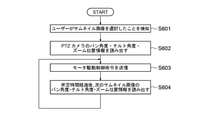
図7(a)に示されるように、システム制御部124(図1)は、まず、ユーザがポインタ701でサムネイル画像504を選択したことを検知する(S601)。その後、システム制御部124は、サムネイル画像504に紐づけられたパン角度、チルト角度およびズーム位置の情報を記憶部125から読み出す(S602)。システム制御部124は、読み出されたパン角度、チルト角度およびズーム位置の情報に基づいて、PTZカメラ120の駆動制御部126にズームモータ127、パンモータ128およびチルトモータ129を駆動させるように命令を送信する(S603)。つまり、システム制御部124は、領域508をPTZカメラ120が撮像するように、駆動制御部126に各モータ127~129の駆動命令を送信する。PTZカメラ120の撮像領域が変更された状態が図7(b)に示されている。
As shown in FIG. 7A, the system control unit 124 (FIG. 1) first detects that the user has selected the
画像201には広角カメラ110が現在撮像している画像が表示されている。よって、ユーザがプリセット位置(領域508)にPTZカメラ120のパン角度、チルト角度、ズーム位置を変更する際にプリセット位置の状況を画像201で確認した上で、PTZカメラ120をパン角度、チルト角度、ズーム位置を変更することができる。
PTZカメラ120が領域508の撮像を所定時間行うと、システム制御部124は、サムネイル画像501に紐づけられたパン角度、チルト角度およびズーム位置の情報を記憶部125から読み出す(S604)。つまり、システム制御部124は、サムネイル画像501を順次自動選択する。そして、システム制御部124は、読み出されたパン角度、チルト角度およびズーム位置の情報に基づいて、PTZカメラ120の駆動制御部126に各モータ127~129を駆動させるように命令を送信する(S603)。このように、巡回設定撮影では、S603の後、サムネイル画像の更新は行わず、S604に進む。そして、S603とS604が繰り返し実行される。巡回設定撮影を停止する場合、例えば、ユーザがUI表示部140からシステム制御部124に停止信号を送信する。
The
When the
なお、上記の説明では、どのサムネイル画像から巡回設定撮影をスタートするかは、ユーザがサムネイル画像を選択することにより決めているが、巡回設定撮影をスタートするサムネイル画像は、あらかじめ設定してもよい。例えば、サムネイル画像501から巡回設定撮影をスタートするように設定してもよい。また、図6のフローチャートでは、ユーザがサムネイル画像504を選択することにより巡回設定撮影が開始したが、巡回設定撮影は、例えば、UI表示部140の電源がオンにされると開始するようにしてもよい。さらに、4つのプリセット位置505~508で撮像を行う時間は、異なっていてもよい。例えば、プリセット位置505で撮像を行う時間は、プリセット位置507で撮像を行う時間より短くてもよい。図7の例では、4つのサムネイル画像501~504を使って巡回設定撮影を行ったが、巡回設定撮影で使用するサムネイル画像の数は4に限定されない。
In the above description, the thumbnail image from which the patrol setting shooting is started is determined by the user selecting the thumbnail image, but the thumbnail image for starting the patrol setting shooting may be set in advance. .. For example, it may be set to start the patrol setting shooting from the
(第2実施形態の効果)
第2実施形態によれば、ユーザがプリセット位置508にPTZカメラ120のパン角度、チルト角度、ズーム位置を変更する際にプリセット位置の現在の状況を確認した上で、PTZカメラ120をパン角度、チルト角度、ズーム位置を変更することができる。また、プリセット位置508の後に自動的に撮像されるプリセット位置505、506および507についても、当該プリセット位置(領域)の現在の状況を確認することができる。さらに、第2実施形態によれば、所定の時間間隔で、複数のプリセット位置(撮像領域)を自動的に巡回して撮像することができる。
(Effect of the second embodiment)
According to the second embodiment, when the user changes the pan angle, tilt angle, and zoom position of the
(変形例)
以上、本発明の好ましい実施形態について説明したが、本発明はこれらの実施形態に限定されず、その要旨の範囲内で種々の変形及び変更が可能である。
例えば、第1実施形態および第2実施形態において、広角カメラ110は、撮像方向およびズーム位置の変更手段を持たない単一のカメラで構成したが、広角カメラ110はこのような構成に限定されない。広角カメラ110は、複数のカメラで構成してもよいし、撮像方向およびズーム位置を変更可能なカメラ(例えば、PTZカメラ)で構成してもよい。
UI表示部140は、例えば、パーソナルコンピュータであるとしたが、サーバにより構成されてもよい。また、広角カメラ110とPTZカメラ120は1つの筐体に収容されるとしたが、別々の筐体に収容されてもよい。つまり、撮像装置100は2つのカメラ(広角カメラ110)が一体化された構造でなくてもよい。
(Modification example)
Although the preferred embodiments of the present invention have been described above, the present invention is not limited to these embodiments, and various modifications and modifications can be made within the scope of the gist thereof.
For example, in the first embodiment and the second embodiment, the wide-
The
(ユーザによる設定変更)
ユーザはサムネイル画像にPTZカメラ120の過去の撮像領域と巡回設定されている撮像領域のどちらを切出して表示させるかをUI表示部140から広角カメラ110に設定変更命令を送信することで切り替えるが可能である。同様にユーザはUI表示部140を介して駆動制御部126に駆動制御命令を送信することで各種モータ(127,128、129)を駆動させ、PTZカメラ120の撮像領域を変更することも可能である。また、サムネイル画像の大きさ、画像の表示位置(レイアウト)もUI表示部140を介して変更可能である。
また、上述の説明では撮像装置100で発明を実施する例について説明したが、本発明をクライアント装置側で実現する様にしてもよい。クライアント装置で実現する場合は、広角カメラ110の画像のどの部分をサムネイルとしてビューワーに表示させるかを示す情報と、各サムネイルが選択された場合にPTZカメラ120をどの位置にPTZ制御させるのかを示す情報をクライアント装置に保持するようにする。また、サムネイルの1つが選択された場合に、対応するPTZ位置にPTZカメラ120を駆動させる命令を発行するようにすればよい。
(Setting change by user)
The user can switch whether to cut out and display the past image pickup area of the
Further, in the above description, an example in which the invention is carried out by the
(その他の実施形態)
上記した実施形態では、撮像装置100を説明したが、本発明はその他の形態でも具現化(実現)することができる。例えば、本発明は、上述した実施形態の1以上の機能を実現するプログラム(コンピュータプログラム)を、ネットワークまたは記録媒体(記憶媒体)を介して、システムまたは装置に供給し、そのシステムまたは装置のコンピュータにおける1つ以上のプロセッサがプログラムを読み出し実行することによっても実現可能である。この場合、記録媒体から読み出されたプログラム(プログラムコード)自体が実施形態の機能を実現することになる。また、当該プログラムを記録した記録媒体は本発明を構成することができる。
また、コンピュータが読み出したプログラムを実行することにより、実施形態の機能が実現されるだけでなく、プログラムの指示に基づき、コンピュータ上で稼働しているオペレーティングシステム(OS)などが実際の処理の一部または全部を行い、その処理によって上記した実施形態の機能が実現されてもよい。
(Other embodiments)
Although the
Further, by executing the program read by the computer, not only the function of the embodiment is realized, but also the operating system (OS) running on the computer is one of the actual processes based on the instruction of the program. The function of the above-described embodiment may be realized by performing a part or all of the processing.
100…撮像装置、110…広角カメラ、120…PTZカメラ、124…システム制御部、140…UI表示部 100 ... Imaging device, 110 ... Wide-angle camera, 120 ... PTZ camera, 124 ... System control unit, 140 ... UI display unit
Claims (17)
前記第一の撮像領域内の第二の撮像領域を撮像する第二の撮像手段と、
前記第二の撮像手段により撮像した第二の撮像領域に対応する位置情報を保持する保持手段と、
前記第一の撮像手段により撮像した撮像画像から、前記保持手段が保持している位置情報に対応する第二の撮像領域の部分画像を出力する出力手段と、
前記出力手段が出力した複数の部分画像のうちの1つが選択されると、当該選択された部分画像に対応する第二の撮像領域を撮像するように、前記第二の撮像手段を制御する制御手段と、
を備えることを特徴とする撮像装置。 The first imaging means for imaging the first imaging region,
A second imaging means for imaging the second imaging region in the first imaging region, and
A holding means for holding position information corresponding to a second image pickup region imaged by the second image pickup means, and a holding means.
An output means for outputting a partial image of a second image pickup region corresponding to the position information held by the holding means from the image captured by the first image pickup means .
When one of the plurality of partial images output by the output means is selected, the second image pickup means is controlled so as to capture a second image pickup region corresponding to the selected partial image . Control means and
An image pickup device characterized by being provided with.
前記制御手段は、前記巡回順序に従って、前記第二の撮像領域を順次撮像するように、前記第二の撮像手段を制御することを特徴とした請求項1に記載の撮像装置。 Further provided with a setting means for setting a cyclic order for the plurality of partial images,
The imaging device according to claim 1, wherein the control means controls the second imaging means so as to sequentially image the second imaging region according to the cyclic order.
第二の撮像手段で撮像している、前記第一の撮像領域より狭い第二の撮像領域の撮像画像を前記表示部にリアルタイムで表示する第二の表示手段と、
前記第二の撮像手段で撮像した第三の撮像領域に対応する撮像画像を、前記第一の撮像手段により撮像した撮像画像から取得して前記表示部に表示する第三の表示手段と、を備えることを特徴とする表示装置。 The first display means for displaying the captured image of the first imaging region captured by the first imaging means on the display unit in real time,
A second display means for displaying the captured image of the second imaging region narrower than the first imaging region on the display unit in real time, which is captured by the second imaging means.
A third display means for acquiring an image captured by the second image pickup means and corresponding to the third image pickup region from the image captured by the first image pickup means and displaying the image on the display unit. A display device characterized by being provided with.
第二の撮像手段で、前記第一の撮像領域内の第二の撮像領域を撮像するステップと、
前記第二の撮像手段により撮像した第二の撮像領域に対応する位置情報を取得するステップと、
前記第一の撮像手段により撮像した撮像画像から、前記取得するステップで取得した位置情報に対応する第二の撮像領域の部分画像を出力するステップと、
前記出力した複数の部分画像のうちの1つが選択されると、当該選択された部分画像に対応する第二の撮像領域を撮像するように、前記第二の撮像手段を制御するステップと、
を有することを特徴とする撮像方法。 The step of imaging the first imaging region with the first imaging means,
A step of imaging a second imaging region in the first imaging region with the second imaging means,
The step of acquiring the position information corresponding to the second imaging region imaged by the second imaging means, and
A step of outputting a partial image of a second imaging region corresponding to the position information acquired in the acquisition step from the image captured by the first imaging means .
When one of the plurality of output partial images is selected, a step of controlling the second imaging means so as to capture a second imaging region corresponding to the selected partial image .
An imaging method characterized by having.
第二の撮像手段で撮像している、前記第一の撮像領域より狭い第二の撮像領域の撮像画像を前記表示部にリアルタイムで表示するステップと、
前記第二の撮像手段で撮像した第三の撮像領域に対応する撮像画像を、前記第一の撮像手段により撮像した撮像画像から取得して前記表示部に表示するステップと、
を有することを特徴とする表示方法。 A step of displaying the captured image of the first imaging region captured by the first imaging means on the display unit in real time.
A step of displaying the captured image of the second imaging region, which is narrower than the first imaging region, captured by the second imaging means on the display unit in real time.
A step of acquiring an image taken by the second image pickup means and corresponding to a third image pickup region from the image taken by the first image pickup means and displaying the image on the display unit .
A display method characterized by having .
Priority Applications (4)
| Application Number | Priority Date | Filing Date | Title |
|---|---|---|---|
| JP2017217225A JP7013210B2 (en) | 2017-11-10 | 2017-11-10 | Imaging device, imaging method, display device and display method |
| US16/182,894 US11463624B2 (en) | 2017-11-10 | 2018-11-07 | Imaging device, imaging method, display device, and display method that capture a particular capturing region corresponding to a selected cutout image |
| CN201811331758.8A CN110022431B (en) | 2017-11-10 | 2018-11-09 | Image pickup apparatus, image pickup method, display apparatus, and display method |
| CN202111211655.XA CN113923360A (en) | 2017-11-10 | 2018-11-09 | Image pickup apparatus, image pickup method, display apparatus, and display method |
Applications Claiming Priority (1)
| Application Number | Priority Date | Filing Date | Title |
|---|---|---|---|
| JP2017217225A JP7013210B2 (en) | 2017-11-10 | 2017-11-10 | Imaging device, imaging method, display device and display method |
Publications (3)
| Publication Number | Publication Date |
|---|---|
| JP2019087974A JP2019087974A (en) | 2019-06-06 |
| JP2019087974A5 JP2019087974A5 (en) | 2020-12-17 |
| JP7013210B2 true JP7013210B2 (en) | 2022-01-31 |
Family
ID=66432607
Family Applications (1)
| Application Number | Title | Priority Date | Filing Date |
|---|---|---|---|
| JP2017217225A Active JP7013210B2 (en) | 2017-11-10 | 2017-11-10 | Imaging device, imaging method, display device and display method |
Country Status (3)
| Country | Link |
|---|---|
| US (1) | US11463624B2 (en) |
| JP (1) | JP7013210B2 (en) |
| CN (2) | CN113923360A (en) |
Families Citing this family (9)
| Publication number | Priority date | Publication date | Assignee | Title |
|---|---|---|---|---|
| US11336831B2 (en) * | 2018-07-06 | 2022-05-17 | Canon Kabushiki Kaisha | Image processing device, control method, and program storage medium |
| JP7252247B2 (en) * | 2019-01-03 | 2023-04-04 | コアフォトニクス リミテッド | Multi-aperture camera comprising at least one camera with two zoom states |
| JP7400248B2 (en) * | 2019-07-31 | 2023-12-19 | 株式会社リコー | mobile object |
| US11228737B2 (en) | 2019-07-31 | 2022-01-18 | Ricoh Company, Ltd. | Output control apparatus, display terminal, remote control system, control method, and non-transitory computer-readable medium |
| CN112399033B (en) | 2019-08-14 | 2022-04-15 | 杭州海康威视数字技术股份有限公司 | Camera assembly and monitoring camera |
| JP7307643B2 (en) | 2019-09-25 | 2023-07-12 | キヤノン株式会社 | IMAGING DEVICE, SYSTEM, CONTROL METHOD OF IMAGING DEVICE, AND PROGRAM |
| JP2021052325A (en) | 2019-09-25 | 2021-04-01 | キヤノン株式会社 | Image capture device, system, method for controlling image capture device, and program |
| JP7328849B2 (en) * | 2019-09-25 | 2023-08-17 | キヤノン株式会社 | IMAGING DEVICE, SYSTEM, CONTROL METHOD OF IMAGING DEVICE, AND PROGRAM |
| EP3869788A1 (en) | 2020-02-19 | 2021-08-25 | Ricoh Company, Ltd. | Image capturing device, image communication system, method for display control, and carrier means |
Citations (3)
| Publication number | Priority date | Publication date | Assignee | Title |
|---|---|---|---|---|
| JP2000032319A (en) | 1998-07-08 | 2000-01-28 | Canon Inc | System, method and device for controlling camera, image processor to be used for the same and record medium |
| WO2009141951A1 (en) | 2008-05-19 | 2009-11-26 | パナソニック株式会社 | Image photographing device and image encoding device |
| JP2011188258A (en) | 2010-03-09 | 2011-09-22 | Canon Inc | Camera system |
Family Cites Families (13)
| Publication number | Priority date | Publication date | Assignee | Title |
|---|---|---|---|---|
| JP3778163B2 (en) | 2002-12-05 | 2006-05-24 | コニカミノルタフォトイメージング株式会社 | Imaging device |
| JP4244973B2 (en) | 2005-08-03 | 2009-03-25 | ソニー株式会社 | Imaging system, camera control device, panoramic image display method and program |
| CN101707671A (en) | 2009-11-30 | 2010-05-12 | 杭州普维光电技术有限公司 | Panoramic camera and PTZ camera combined control method and panoramic camera and PTZ camera combined control device |
| JP2011188210A (en) * | 2010-03-08 | 2011-09-22 | Olympus Imaging Corp | Photographing apparatus and photographing system |
| JP2013219556A (en) | 2012-04-09 | 2013-10-24 | Olympus Imaging Corp | Imaging apparatus |
| JP2013251783A (en) | 2012-06-01 | 2013-12-12 | Canon Inc | Imaging apparatus and imaging control method |
| JP6231768B2 (en) | 2013-04-26 | 2017-11-15 | キヤノン株式会社 | Imaging apparatus and control method thereof |
| JP6261191B2 (en) | 2013-05-31 | 2018-01-17 | キヤノン株式会社 | Display control apparatus, display control method, and program |
| KR20150021353A (en) | 2013-08-20 | 2015-03-02 | 삼성테크윈 주식회사 | Image systhesis system and image synthesis method |
| CN104052931A (en) | 2014-06-27 | 2014-09-17 | 宇龙计算机通信科技(深圳)有限公司 | Image shooting device, method and terminal |
| JP6469977B2 (en) | 2014-07-09 | 2019-02-13 | オリンパス株式会社 | Specimen observation apparatus and specimen observation method |
| CN106455943B (en) | 2014-11-21 | 2018-12-04 | 奥林巴斯株式会社 | The working method of photographic device, image processing apparatus, photographic device |
| CN105933660A (en) | 2016-05-20 | 2016-09-07 | 北京格灵深瞳信息技术有限公司 | Monitoring image pick-up apparatus |
-
2017
- 2017-11-10 JP JP2017217225A patent/JP7013210B2/en active Active
-
2018
- 2018-11-07 US US16/182,894 patent/US11463624B2/en active Active
- 2018-11-09 CN CN202111211655.XA patent/CN113923360A/en active Pending
- 2018-11-09 CN CN201811331758.8A patent/CN110022431B/en active Active
Patent Citations (3)
| Publication number | Priority date | Publication date | Assignee | Title |
|---|---|---|---|---|
| JP2000032319A (en) | 1998-07-08 | 2000-01-28 | Canon Inc | System, method and device for controlling camera, image processor to be used for the same and record medium |
| WO2009141951A1 (en) | 2008-05-19 | 2009-11-26 | パナソニック株式会社 | Image photographing device and image encoding device |
| JP2011188258A (en) | 2010-03-09 | 2011-09-22 | Canon Inc | Camera system |
Also Published As
| Publication number | Publication date |
|---|---|
| US20190149744A1 (en) | 2019-05-16 |
| CN113923360A (en) | 2022-01-11 |
| CN110022431A (en) | 2019-07-16 |
| JP2019087974A (en) | 2019-06-06 |
| CN110022431B (en) | 2021-10-22 |
| US11463624B2 (en) | 2022-10-04 |
Similar Documents
| Publication | Publication Date | Title |
|---|---|---|
| JP7013210B2 (en) | Imaging device, imaging method, display device and display method | |
| KR101655056B1 (en) | Wireless video camera | |
| JP6497965B2 (en) | Image processing apparatus and image processing method | |
| JP7150456B2 (en) | IMAGING SYSTEM, INFORMATION PROCESSING DEVICE, CONTROL METHOD OF INFORMATION PROCESSING DEVICE, AND PROGRAM | |
| JP6261191B2 (en) | Display control apparatus, display control method, and program | |
| JP2007096532A (en) | Image storage apparatus and image storage system | |
| JP6256298B2 (en) | IMAGING DEVICE, ITS CONTROL METHOD AND PROGRAM | |
| JP5939902B2 (en) | Control device and control method of control device | |
| JP2021100238A (en) | Image processing device, imaging apparatus, and image processing method | |
| JP2010062834A (en) | Photographing system, photographing device constituting the same, and operation device | |
| JP2015035686A (en) | Camera apparatus, monitoring system, control device, and control program | |
| JP5917175B2 (en) | IMAGING DEVICE, IMAGING DEVICE DISTRIBUTION METHOD, IMAGING SYSTEM, AND PROGRAM | |
| JP2017216599A (en) | Imaging apparatus and control method therefor | |
| JP6551496B2 (en) | Image pickup apparatus, control method thereof and program | |
| JP2023064291A (en) | Device and method for controlling imaging apparatus, and program | |
| JP6702675B2 (en) | IMAGING DEVICE, IMAGING DEVICE CONTROL METHOD, AND PROGRAM | |
| JP2006098547A (en) | Camera device and lens filter device | |
| JP2016045471A (en) | Imaging device and control method of the same, program thereof and recording medium | |
| JP2024017812A (en) | Information processing apparatus, information processing method, and program | |
| JP2023086483A (en) | Image processing device, image processing method, and program | |
| JP6271988B2 (en) | Imaging apparatus, control method therefor, and program | |
| CN114760412A (en) | Method and device for acquiring full-field high-sharpness image and movable platform | |
| JP2019133691A (en) | Image processing apparatus and image processing method | |
| JP2009200793A (en) | Electronic camera, and image processing program | |
| JPH11103410A (en) | Camera control system, camera control method and storage medium stored with program executing processing therefor |
Legal Events
| Date | Code | Title | Description |
|---|---|---|---|
| A521 | Request for written amendment filed |
Free format text: JAPANESE INTERMEDIATE CODE: A523 Effective date: 20201104 |
|
| A621 | Written request for application examination |
Free format text: JAPANESE INTERMEDIATE CODE: A621 Effective date: 20201104 |
|
| A977 | Report on retrieval |
Free format text: JAPANESE INTERMEDIATE CODE: A971007 Effective date: 20211116 |
|
| TRDD | Decision of grant or rejection written | ||
| A01 | Written decision to grant a patent or to grant a registration (utility model) |
Free format text: JAPANESE INTERMEDIATE CODE: A01 Effective date: 20211221 |
|
| A61 | First payment of annual fees (during grant procedure) |
Free format text: JAPANESE INTERMEDIATE CODE: A61 Effective date: 20220119 |