JP7006018B2 - Thermal transfer printing system - Google Patents
Thermal transfer printing system Download PDFInfo
- Publication number
- JP7006018B2 JP7006018B2 JP2017161402A JP2017161402A JP7006018B2 JP 7006018 B2 JP7006018 B2 JP 7006018B2 JP 2017161402 A JP2017161402 A JP 2017161402A JP 2017161402 A JP2017161402 A JP 2017161402A JP 7006018 B2 JP7006018 B2 JP 7006018B2
- Authority
- JP
- Japan
- Prior art keywords
- layer
- image
- thermal transfer
- unit
- sheet
- Prior art date
- Legal status (The legal status is an assumption and is not a legal conclusion. Google has not performed a legal analysis and makes no representation as to the accuracy of the status listed.)
- Active
Links
Images


Landscapes
- Impression-Transfer Materials And Handling Thereof (AREA)
- Electronic Switches (AREA)
Description
本発明は、熱転写印画装置、熱転写印画システム及び熱転写印画方法に関する。 The present invention relates to a thermal transfer printing device, a thermal transfer printing system, and a thermal transfer printing method.
従来、染料層を備えた熱転写シートと、被転写体となる受像シートとを重ね合わせ、サーマルヘッドと呼ばれる熱源からの熱エネルギーを熱転写シートへ印加し、熱転写シート中の染料を受像シートへ転写することで画像を形成する熱転写プリンタが知られている。 Conventionally, a thermal transfer sheet provided with a dye layer and an image receiving sheet to be transferred are superposed, heat energy from a heat source called a thermal head is applied to the thermal transfer sheet, and the dye in the thermal transfer sheet is transferred to the image receiving sheet. Thermal transfer printers that form images are known.
例えば、特許文献1には、基材シート、断熱層、及び受容層が積層された受像シートの、基材シートと断熱層との間、及び/又は断熱層と受容層との間にさらにクッション層を設けることで、受像シートの表面を平坦化することが開示されている。
For example, in
また、特許文献2には、受像シートの染料受容層の表面を熱処理することで、熱転写プリンタ内の搬送系の機構部品等の接触により変化した受像シートの表面性(平滑度)を改善する手法が開示されている。
Further,
このように、従来は、表面が平滑な受像シートに染料を転写して画像を形成していたため、作製される印画物は、見た目や触感等の風合いが画一的であり、面白味に欠けることがあった。 In this way, conventionally, the dye is transferred to an image receiving sheet having a smooth surface to form an image, so that the printed matter to be produced has a uniform texture such as appearance and touch, and is not interesting. was there.
本発明は、風合いの異なる印画物を作製することができる熱転写印画装置、熱転写印画システム及び熱転写印画方法を提供することを目的とする。 An object of the present invention is to provide a thermal transfer printing device, a thermal transfer printing system, and a thermal transfer printing method capable of producing printed objects having different textures.
本発明の熱転写印画装置は、受容層を含む転写層と染料層とが設けられた熱転写シートを供給する供給部と、前記供給部から供給された熱転写シートの前記転写層を加熱し、受像シート上に前記転写層を転写して前記受像シートの表面に凹凸加工を施し、前記染料層を加熱して、前記受像シート及び転写された前記転写層に染料を転写して画像を形成する加熱部と、を備えるものである。 The heat transfer printing apparatus of the present invention heats a supply unit provided with a transfer layer including a receiving layer and a dye layer to supply a heat transfer sheet, and the transfer layer of the heat transfer sheet supplied from the supply unit to heat an image receiving sheet. A heating unit that transfers the transfer layer onto the image-receiving sheet to perform uneven processing on the surface of the image-receiving sheet, heats the dye layer, and transfers the dye to the image-receiving sheet and the transferred transfer layer to form an image. And.
本発明の一態様では、前記加熱部は、前記熱転写シートの第1転写層を前記受像シート上に転写し、第1染料層を加熱して前記受像シート及び前記第1転写層に染料を転写して第1画像を形成し、第2転写層を前記受像シートの前記第1画像上に転写し、第2染料層を加熱して前記第2転写層に染料を転写して第2画像を形成する。 In one aspect of the present invention, the heating unit transfers the first transfer layer of the thermal transfer sheet onto the image receiving sheet, heats the first dye layer, and transfers the dye to the image receiving sheet and the first transfer layer. The first image is formed, the second transfer layer is transferred onto the first image of the image receiving sheet, the second dye layer is heated, and the dye is transferred to the second transfer layer to obtain the second image. Form.
本発明の一態様では、前記熱転写シートは、前記転写層が設けられた第1熱転写シート及び前記染料層が設けられた第2熱転写シートを含み、前記供給部は、前記第1熱転写シートを供給する第1供給部、及び前記第2熱転写シートを供給する第2供給部を有し、前記加熱部は、前記第1熱転写シートを加熱して前記受像シート上に前記転写層を転写する第1加熱部、及び前記第2熱転写シートを加熱して前記受像シート及び転写された前記転写層に染料を転写して画像を形成する第2加熱部を有する。 In one aspect of the present invention, the thermal transfer sheet includes a first thermal transfer sheet provided with the transfer layer and a second thermal transfer sheet provided with the dye layer, and the supply unit supplies the first thermal transfer sheet. The first supply unit is provided with a first supply unit and a second supply unit for supplying the second thermal transfer sheet, and the heating unit heats the first thermal transfer sheet to transfer the transfer layer onto the image receiving sheet. It has a heating unit and a second heating unit that heats the second thermal transfer sheet to transfer a dye to the image receiving sheet and the transferred transfer layer to form an image.
本発明の熱転写印画システムは、本発明による熱転写印画装置と、画像データの入力を受け付ける入力部と、入力画像を表示する表示部と、入力画像に凹凸加工を施す加工領域の指定を受け付ける加工領域指定部と、前記画像データ及び指定された加工領域に関する情報を前記熱転写印画装置へ出力する印画制御部と、を備えるものである。 The thermal transfer printing system of the present invention is a thermal transfer printing apparatus according to the present invention, an input unit that accepts input of image data, a display unit that displays an input image, and a processing area that accepts designation of a processing area for performing uneven processing on the input image. It includes a designated unit and a printing control unit that outputs information about the image data and the designated processing area to the thermal transfer printing apparatus.
本発明の一態様では、前記加工領域指定部は、さらに凹凸加工のパターンの指定を受け付ける。 In one aspect of the present invention, the processing area designation unit further accepts designation of a pattern for uneven processing.
本発明の一態様では、前記入力画像内の物体領域を抽出する画像処理部をさらに備え、抽出された物体領域、又は前記物体領域の輪郭部を加工領域とする。 In one aspect of the present invention, an image processing unit for extracting an object region in the input image is further provided, and the extracted object region or the contour portion of the object region is used as a processing region.
本発明の熱転写印画方法は、受容層を含む転写層と染料層とが設けられた熱転写シートの前記転写層を加熱し、受像シート上に前記転写層を転写し、前記受像シートの表面に凹凸加工を施す工程と、前記染料層を加熱して、前記受像シート及び転写された前記転写層に染料を転写して画像を形成する工程と、を備えるものである。 In the thermal transfer printing method of the present invention, the transfer layer of the thermal transfer sheet provided with the transfer layer including the receiving layer and the dye layer is heated, the transfer layer is transferred onto the image receiving sheet, and the surface of the image receiving sheet is uneven. It includes a step of performing processing and a step of heating the dye layer and transferring the dye to the image receiving sheet and the transferred transfer layer to form an image.
本発明によれば、熱転写シートから受像シートに転写層を転写して受像シートの表面に凹凸加工を施し、受像シートの凹凸面に染料を転写して画像を形成することにより、風合いの異なる印画物を作製することができる。 According to the present invention, a transfer layer is transferred from a thermal transfer sheet to an image receiving sheet, the surface of the image receiving sheet is subjected to uneven processing, and a dye is transferred to the uneven surface of the image receiving sheet to form an image, thereby printing images having different textures. You can make things.
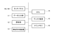
図1は本発明の実施の形態に係る熱転写印画システムの外観図であり、図2は熱転写印画システムのブロック構成図である。熱転写印画システムは、タッチパネル(表示部、操作部)10A、10B、データ入力部11、課金部12、熱転写印画装置13、CPU(中央処理部)14、ディスク装置(記憶部)15、及びメインメモリ16を有する。熱転写印画システムの各部はバスを介して接続されている。
FIG. 1 is an external view of the thermal transfer printing system according to the embodiment of the present invention, and FIG. 2 is a block configuration diagram of the thermal transfer printing system. The thermal transfer printing system includes a touch panel (display unit, operation unit) 10A and 10B, a
タッチパネル10A、10Bは、画像を含む情報を表示したり、利用者から各種指示の入力を受け付けたりする。例えば、タッチパネル10A、10Bは、利用者から、プリント出力する画像データの選択、選択された画像データのプリント枚数やプリントサイズの指定、凹凸加工の有無、凹凸加工領域の指定などを受け付ける。凹凸加工については後述する。
The
タッチパネル10Bは、熱転写印画システムの筐体1の上部に設けられ、ディスプレイ画面は略垂直に立った状態となっている。タッチパネル10Aは、筐体1の天板1A部分に設けられている。タッチパネル10Aへの入力操作を行い易いように、天板1A及びタッチパネル10Aの画面は、手前側が低く奥側が高くなるようにやや傾斜している。本実施形態では、2つのタッチパネルを搭載した例について説明するが、タッチパネルは1つでもよいし、3つ以上搭載されていてもよい。
The
データ入力部11は、デジタルカメラ等で撮影した画像データが記憶された記憶媒体から画像データを読み取ることで、画像データの入力を受け付ける。データ入力部11は、様々な記憶媒体に対応したデータ読取装置を有している。また、データ入力部11は、無線通信により携帯端末から画像データの入力を受け付けることができる。図1に示すように、データ入力部11はタッチパネル10Aとタッチパネル10Bとの間に設けられている。
The
課金部12は、筐体1の前面側に設けられた硬貨投入口12A、紙幣投入口12B、釣銭返却口12Cを有し、硬貨投入口12A及び紙幣投入口12Bから投入された貨幣を識別計数し、釣銭を釣銭返却口12Cから放出する。また、課金部12は、電子マネーによる決済機能を有していてもよい。また、課金部12は、プリント枚数、単価、請求金額、投入金額、釣銭額等をレシートに印字して出力するレシートプリンタを有していてもよい。レシートプリンタはデータ入力部11の近傍に配置されていてもよい。
The
熱転写印画装置13は、昇華型熱転写方式の高解像度カラープリンタであり、注文内容に基づいて、画像データをプリントして出力する。熱転写印画装置13は筐体1内に1台又は複数台収容される。
The thermal
筐体1の前面側には、開閉扉2が開閉自在に設けられている。開閉扉2の裏面側には、集積部が設けられており、開閉扉2を開けると集積部に集積された印画物40a(図4参照)が取り出せるようになっている。
An opening /
ディスク装置15には印画処理プログラムが格納されている。CPU14が印画処理プログラムをメインメモリ16にロードして実行することで、図3に示すように、画像処理部61、表示処理部62、加工領域指定部63、注文受付部64及び印画制御部65が実現される。各部の処理については後述する。
A printing processing program is stored in the
図4は、熱転写印画装置13の概略構成図であり、図5は、熱転写印画装置13で用いられる熱転写シート30の平面図であり、図6は熱転写シート30の長手方向に沿った断面図である。図7は、受像シート40の断面図である。
FIG. 4 is a schematic configuration diagram of the thermal
熱転写シート30は、図5,図6のように、基材フィルム35の一方の面に転写層31及び染料層32が面順次に繰り返し設けられ、基材フィルム35の他方の面に背面層36が設けられた構成を有する。染料層32は、面順次に設けられたイエロー染料層(Y層)、マゼンタ染料層(M層)、及びシアン染料層(C層)を含む。
In the
転写層31は、受容層38のみからなる単層構成、又は積層構成をなしている。図5に示す形態では、転写層31は、剥離層37、受容層38及び接着層39がこの順で積層された積層構成をなしている。
The
熱転写印画装置は、熱転写シート30及びサーマルヘッド(加熱部)21を用いて、受像シート40(印画紙)上に転写層31を転写し、続いて、Y、M、Cを昇華転写させて画像を形成する。
The thermal transfer printing apparatus transfers the
サーマルヘッド21の下流側に、熱転写シート30をボビンに巻き付けて形成された供給部23が設けられ、サーマルヘッド21の上流側に、巻取ボビンを有する回収部24が設けられている。供給部23から繰り出された熱転写シート30は、サーマルヘッド21を通って回収部24に回収(巻き取り)されるようになっている。
A
サーマルヘッド21の下方側には回転自在なプラテンロール22が設けられている。サーマルヘッド21とプラテンロール22との間に、受像シート40及び熱転写シート30を挟み込み、サーマルヘッド21で熱転写シート30を加熱することで、受像シート40上に転写層31を転写したり、染料を転写して画像を形成したりする。
A
サーマルヘッド21の上流側には、受像シート40の搬送を行うための回転駆動自在なキャプスタンローラ29aとピンチローラ29bとが設けられている。
On the upstream side of the
受像シート40は、受像紙ロール26に巻き付けられており、受像紙ロール26から繰り出される。受像紙ロール26、キャプスタンローラ29a、及びピンチローラ29bにより受像シート40の繰り出し(前方側への搬送)や巻取り(後方側への搬送)が行われる。
The
図7に示すように、受像シート40は、基材シート41の一方の面に受容層42を設け、基材シート41の他方の面に裏面層43を設けた構成である。裏面層43は省略してもよい。
As shown in FIG. 7, the
転写層31の転写及び染料の転写が施された受像シート40は、下流側でカッター28により印画物40aとして切り出される。
The
熱転写印画装置13を用いた印画処理の一態様では、まず、受像シート40と熱転写シート30の転写層31とが位置合わせされ、受像シート40及び熱転写シート30を介してサーマルヘッド21がプラテンロール22に当接する。次に、キャプスタンローラ29a及び回収部24が回転駆動して、受像シート40及び熱転写シート30が送られる。この間、所定のパターンに基づいて、サーマルヘッド21により転写層31が選択的に順次加熱され、熱転写シート30から受像シート40上に転写層31(受容層38及び接着層39)が転写される。
In one aspect of the printing process using the thermal
これにより、図8(a)(b)に示すように、受像シート40の受容層42上に転写層31が所定のパターンで転写され、転写層31部分が凸部となる。転写層31を転写することで、受像シート40の表面を凹凸加工することができる。
As a result, as shown in FIGS. 8A and 8B, the
転写層31の転写後、サーマルヘッド21が上昇し、プラテンロール22から離れる。次に、受像シート40と染料層32のY層とが位置合わせされ、受像シート40及び熱転写シート30が、サーマルヘッド21及びプラテンロール22に挟み込まれる。キャプスタンローラ29a及び回収部24が回転駆動して、受像シート40及び熱転写シート30が送られる。この間、画像データに基づいて、サーマルヘッド21によりY層の領域が選択的に順次加熱され、Y層から受像シート40の受容層42及び転写層31の受容層38にイエロー染料が転写される。
After the transfer of the
イエロー染料の転写後、サーマルヘッド21が上昇し、プラテンロール22から離れる。次に、受像シート40とM層とが位置合わせされる。イエロー染料を転写する方法と同様にして、画像データに基づいてM層及びC層が加熱され、受容層42及び受容層38にマゼンタ染料及びシアン染料が転写される。これにより、図9(a)(b)、図10に示すように、表面に凹凸加工が施された受像シート40上に画像50が形成される。図9(a)と図9(b)は、受像シート40の異なる領域の断面の一例を示している。
After the transfer of the yellow dye, the
利用者が、図1に示す熱転写印画システムに画像データを入力すると、画像処理部61が画像データのリサイズ処理を行い、プレビュー用画像を生成する。表示処理部62は、プレビュー用画像をタッチパネル10Aに表示する。利用者はタッチパネル10Aを操作して、プリントする画像やプリント枚数を選択したり、上述のような凹凸加工を施すか否か選択したりして、プリント注文を行う。
When the user inputs the image data into the thermal transfer printing system shown in FIG. 1, the image processing unit 61 resizes the image data and generates a preview image. The display processing unit 62 displays the preview image on the
加工領域指定部63は、利用者から凹凸加工のパターンや、加工を施す領域の指定を受け付ける。例えば、熱転写印画システムは、「木目調」「市松模様」「グレンチェック」「杉綾」など、凹凸加工のパターン(模様)を複数種類準備している。利用者は、タッチパネル10Aを操作して、パターン種類や、凹凸パターンを加工する領域を指定する。
The processing
例えば、利用者は、図11(a)に示すプリント画像を選択後、図11(b)に示すように、画像全体に凹凸加工を施すこと、及び凹凸加工のパターンを指定する。あるいはまた、利用者は、図11(c)に示すように、画像内の物体の輪郭に沿って凸部や凹凸パターンが設けられるように指定してもよい。 For example, after selecting the print image shown in FIG. 11A, the user performs unevenness processing on the entire image and specifies a pattern of unevenness processing as shown in FIG. 11B. Alternatively, as shown in FIG. 11 (c), the user may specify that a convex portion or an uneven pattern is provided along the contour of the object in the image.
また、画像処理部61が画像内の人物領域(又は物体領域)を自動抽出し、抽出領域内に凹凸パターンを加工したり、抽出領域の輪郭部に凸部や凹凸パターンを設けたりすることが指定できるようにしてもよい。 Further, the image processing unit 61 automatically extracts a person area (or an object area) in the image, processes an uneven pattern in the extracted area, or provides a convex portion or an uneven pattern in the contour portion of the extracted area. It may be possible to specify.
画像処理部61が、入力画像を絵画風(油絵風、水彩画風)に変換し、凹凸加工が施された受像シート40上に変換画像が印画されるようにしてもよい。
The image processing unit 61 may convert the input image into a painting style (oil painting style, watercolor painting style), and print the converted image on the
注文受付部64は、プリント注文を受け付け、課金部12を用いて課金処理を行う。
The order receiving unit 64 receives a print order and performs a charging process using the charging
印画制御部65は、画像データ、凹凸加工のパターンや加工領域に関する情報を熱転写印画装置13へ出力する。熱転写印画装置13は、上述した印画処理により、受像シート40の表面に凹凸加工を施し、この凹凸面に画像を形成する。熱転写印画システムは、表面が平滑な受像シートに画像を形成した場合とは、見た目や触感等の風合いが異なる印画物を作製することができ、利用者に対して印画物の新たな楽しみ方、面白味を提供できる。
The printing control unit 65 outputs image data, information regarding the pattern of unevenness processing and the processing area to the thermal
転写層31及び染料層32を複数使用し、受像シート40の同一画面で、転写層31の転写及び画像形成を複数回繰り返し行ってもよい。例えば、図12(a)に示すように、受像シート40上に転写層31Aを転写する。次に、染料層32の染料を受像シート40及び転写層31Aに転写して、図12(b)に示すように、画像50Aを形成する。
A plurality of transfer layers 31 and dye layers 32 may be used, and the transfer and image formation of the
続いて、図12(c)に示すように、受像シート40上に転写層31Bを転写する。転写層31Bは、受容層42上に転写してもよいし、既に転写されている転写層31A上に転写してもよい。次に、染料層32の染料を受像シート40及び転写層31Bに転写して、図12(d)に示すように、画像50Bを形成する。図13に示すように、転写層31Bは、転写層31Aの一部に重なるように設けられていてもよい。
Subsequently, as shown in FIG. 12 (c), the
このように、転写層31の転写及び画像形成を複数回繰り返し行うことで、立体的な奥行きのある画像が形成された印画物を作製できる。 By repeating the transfer and image formation of the transfer layer 31 a plurality of times in this way, it is possible to produce a printed matter in which an image having a three-dimensional depth is formed.
染料層32から受像シート40に染料を転写して画像を形成した後、転写層31を転写してもよい。例えば、図14(a)に示すように、染料層32の染料を受像シート40に転写して、画像50を形成する。その後、図14(b)に示すように、受像シート40上に転写層31を転写する。このような方法であっても、表面に凹凸加工を施した印画物を作製できる。
After transferring the dye from the
上記実施形態では、転写層31及び染料層32が面順次に繰り返し設けられた熱転写シート30を用いる例について説明したが、転写層31が設けられた第1熱転写シートと染料層32が設けられた第2熱転写シートを用いてもよい。この場合、熱転写印画装置は、第1熱転写シートを繰り出す第1供給部、第1熱転写シートを加熱して受像シート40に転写層31を転写する第1サーマルヘッド(第1加熱部)、第1熱転写シートを回収する第1回収部、第2熱転写シートを繰り出す第2供給部、第2熱転写シートを加熱して受像シート40にY,M,Cを転写して画像を形成する第2サーマルヘッド(第2加熱部)、第2熱転写シートを回収する第2回収部を備える。
In the above embodiment, an example of using the
次に、熱転写シート30を構成する材料について説明する。
Next, the material constituting the
[基材フィルム]
熱転写シート30に用いられる基材フィルム35は、ある程度の耐熱性と強度を有するものであれば、いずれのものでもよい。例えば、ポリエチレンテレフタレートフィルム、1,4-ポリシクロヘキシレンジメチレンテレフタレートフィルム、ポリエチレンナフタレートフィルム、ポリフェニレンサルフィドフィルム、ポリスチレンフィルム、ポリプロピレンフィルム、ポリサルホンフィルム、アラミドフィルム、ポリカーボネートフィルム、ポリビニルアルコールフィルム、セロハン、酢酸セルロース等のセルロース誘導体、ポリエチレンフィルム、ポリ塩化ビニルフィルム、ナイロンフィルム、ポリイミドフィルム、アイオノマーフィルム等の樹脂フィルム等が挙げられる。また、基材フィルムと背面層との間に、プライマー層(接着層)を塗工して形成することも可能である。プライマー層は、例えば、ポリエステル系樹脂、ポリアクリル酸エステル系樹脂、ポリ酢酸ビニル系樹脂、ポリウレタン系樹脂、スチレンアクリレート系樹脂、ポリアクリルアミド系樹脂、ポリアミド系樹脂、ポリエーテル系樹脂、ポリスチレン系樹脂、ポリエチレン系樹脂、ポリプロピレン系樹脂、ポリ塩化ビニル樹脂やポリビニルアルコール樹脂、ポリ塩化ビニリデン樹脂等のビニル系樹脂、ポリビニルアセトアセタールやポリビニルブチラール等のポリビニルアセタール系樹脂、セルロース系樹脂等を用いて形成することができる。
[Base film]
The
[染料層]
染料層32は、バインダ樹脂に、昇華性染料を溶融又は分散させた材料を用いることが好ましい。昇華性染料としては、例えば、ジアリールメタン系染料;トリアリールメタン系染料;チアゾール系染料;メロシアニン染料;ピラゾロン染料;メチン系染料;インドアニリン系染料;アセトフェノンアゾメチン、ピラゾロアゾメチン、イミダゾルアゾメチン、イミダゾアゾメチン、ピリドンアゾメチン等のアゾメチン系染料;キサンテン系染料;オキサジン系染料;ジシアノスチレン、トリシアノスチレン等のシアノスチレン系染料;チアジン系染料;アジン系染料;アクリジン系染料;ベンゼンアゾ系染料;ピリドンアゾ、チオフェンアゾ、イソチアゾールアゾ、ピロールアゾ、ピラゾールアゾ、イミダゾールアゾ、チアジアゾールアゾ、トリアゾールアゾ、ジスアゾ等のアゾ系染料;スピロピラン系染料;インドリノスピロピラン系染料;フルオラン系染料;ローダミンラクタム系染料;ナフトキノン系染料;アントラキノン系染料;キノフタロン系染料;等が挙げられる。
[Dye layer]
For the
染料層32は、離型剤、無機微粒子、有機微粒子等の添加剤を使用してもよい。離型剤としては、シリコーンオイル、リン酸エステル等が挙げられる。無機微粒子としては、カーボンブラック、アルミニウム、二硫化モリブデン等が挙げられる。また、有機微粒子としては、ポリエチレンワックス等が挙げられる。
For the
[背面層]
背面層36は、基材フィルムの背面に、耐熱性及び印画時におけるサーマルヘッドの走行性等を向上させるために設けられる。
[Back layer]
The
背面層36は、熱可塑性樹脂等を適宜選択して形成することができる。このような、熱可塑性樹脂として、例えば、ポリエステル系樹脂、ポリアクリル酸エステル系樹脂、ポリ酢酸ビニル系樹脂、スチレンアクリレート系樹脂、ポリウレタン系樹脂、ポリエチレン系樹脂、ポリプロピレン系樹脂等のポリオレフィン系樹脂、ポリスチレン系樹脂、ポリ塩化ビニル系樹脂、ポリエーテル系樹脂、ポリアミド系樹脂、ポリイミド系樹脂、ポリアミドイミド系樹脂、ポリカーボネート系樹脂、ポリアクリルアミド樹脂、ポリビニルクロリド樹脂、ポリビニルブチラール樹脂やポリビニルアセトアセタール樹脂等のポリビニルアセタール樹脂等の熱可塑性樹脂、これらのシリコーン変性物等が挙げられる。
The
また、背面層36には、上記熱可塑性樹脂に加え、スリップ性を向上させる目的で、ワックス、高級脂肪酸アミド、リン酸エステル化合物、金属石鹸、シリコーンオイル、界面活性剤等の離型剤、フッ素樹脂等の有機粒子を含有することができる。また、背面層には、タルク、シリカ、クレー、炭酸カルシウム等の無機粒子が添加されてもよい。
Further, in addition to the above-mentioned thermoplastic resin, the
[剥離層]
剥離層37の成分としては、例えば、ワックス類、シリコーンワックス、シリコーン樹脂、シリコーン変性樹脂、フッ素樹脂、フッ素変性樹脂、ポリビニルアルコール樹脂、アクリル系樹脂、ポリエステル系樹脂、熱架橋性エポキシ-アミノ樹脂及び熱架橋性アルキッド-アミノ樹脂等を挙げることができる。また、剥離層37は、これらの成分の1種を単独で含有していてもよく、2種以上を含有していてもよい。剥離層37の厚みについて特に限定はないが、一例としては、0.5μm以上5μm以下の範囲である。
[Release layer]
The components of the
[受容層]
受容層38について特に限定はない。受容層38の成分としては、例えば、ポリプロピレン等のポリオレフィン系樹脂、ポリ塩化ビニルもしくはポリ塩化ビニリデン等のハロゲン化樹脂、ポリ酢酸ビニルや塩化ビニル-酢酸ビニル共重合体、エチレン-酢酸ビニル共重合体もしくはポリアクリル酸エステル等のビニル系樹脂、ポリエチレンテレフタレートもしくはポリブチレンテレフタレート等のポリエステル系樹脂、ポリスチレン系樹脂、ポリアミド系樹脂、エチレンもしくはプロピレン等のオレフィンと他のビニルポリマーとの共重合体、アイオノマーもしくはセルロースジアスターゼ等のセルロース系樹脂、ポリカーボネート、アクリル系樹脂等の溶剤系の樹脂を挙げることができる。中でも、ポリエステル系樹脂、塩化ビニル-酢酸ビニル共重合体を用いることが好ましく、塩化ビニル-酢酸ビニル共重合体を用いることがさらに好ましい。また、受容層38は、これらの成分の1種を単独で含有していてもよく、2種以上を含有していてもよい。
[Receptive layer]
The receiving
また、受容層38は、上記樹脂成分とともに、離型剤を含有していてもよい。離型剤としては、例えば、ポリエチレンワックス、アミドワックス、テフロン(登録商標)パウダー等の固形ワックス類、フッ素系またはリン酸エステル系界面活性剤、シリコーンオイル、反応性シリコーンオイル、硬化型シリコーンオイル等の各種変性シリコーンオイル、および各種シリコーン樹脂などを挙げることができる。
Further, the receiving
受容層38の厚みについて特に限定はないが、一例としては、1μm以上10μm以下の範囲である。
The thickness of the receiving
[接着層]
接着層39の成分としては、例えば、アクリル系樹脂、塩化ビニル系樹脂、酢酸ビニル系樹脂、塩化ビニル-酢酸ビニル共重合体、スチレン─アクリル共重合体、ポリエステル系樹脂、ポリアミド系樹脂等を挙げることができる。接着層39の厚みについて特に限定はないが、通常、0.1μm以上5μm以下の範囲内である。
[Adhesive layer]
Examples of the components of the
次に、受像シート40を構成する材料について説明する。
Next, the materials constituting the
[基材シート]
基材シート41としては、受容層42及び必要に応じて設けられたその他の層を支持し、熱転写時の加熱に耐えられるものであれば特に限定されない。例えば、ポリエチレンテレフタレート、ポリエチレンナフタレート等の耐熱性の高いポリオレフィン、ポリエステル、ポリプロピレン、ポリカーボネート、酢酸セルロース、ポリエチレン誘導体、ポリアミド、ポリメチルペンテン等のプラスチックの延伸または未延伸フィルムや、これらの合成樹脂に白色顔料や充填剤を加えて成膜した白色不透明フィルムも使用できる。これ以外にも、上質紙、コート紙、アート紙、キャストコート紙、板紙等の材料も使用することができる。また、これらの材料を2種以上積層した複合フィルムも使用することができる。代表的な積層体の例として、セルロース繊維紙と合成紙或いはセルロース合成紙とプラスチックフィルムと合成紙が挙げられる。
[Base sheet]
The
基材シート41の厚さは、その強度および耐熱性等が適切になるように材料に応じて適宜選択することができるが、通常1μm以上300μm以下、好ましくは60μm以上200μm以下程度である。
The thickness of the
[受容層]
受容層42は熱転写シート30から移行してくる染料を受容し、形成された画像を維持するためのものである。受容層42を形成するための樹脂としては、ポリカーボネート系樹脂、ポリエステル系樹脂、ポリアミド系樹脂、アクリル系樹脂、セルロース系樹脂、ポリスルフォン系樹脂、ポリ塩化ビニル樹脂、ポリ酢酸ビニル樹脂、塩化ビニル-酢酸ビニル共重合体、ポリビニルアセタール樹脂、ポリビニルブチラール樹脂、ポリウレタン系樹脂、ポリスチレン系樹脂、ポリプロピレン系樹脂、ポリエチレン系樹脂、エチレン-酢酸ビニル共重合体、およびエポキシ樹脂等が挙げられる。なお、受容層42を形成するための樹脂は、いわゆる溶剤系であっても水系であってもよい。
[Receptive layer]
The receiving
[裏面層]
裏面層43は、バインダ樹脂と、フッ素系樹脂微粒子とを含むものであり、ポリアミド系樹脂微粒子をさらに含んでもよい。バインダ樹脂としては、例えば、ポリビニルブチラール樹脂、ポリビニルアセタール樹脂、アクリル樹脂が挙げられ、ポリビニルブチラール樹脂を用いることが好ましい。フッ素系樹脂微粒子としては、例えば、ポリテトラフルオロエチレン(PTFE)微粒子、ポリクロロトリフルオロエチレン(PCTFE)微粒子、ポリフッ化ビニリデン(PVDF)微粒子、およびポリフッ化ビニル(PVF)微粒子等が挙げられ、PTFE微粒子を用いることが好ましい。裏面層43にフッ素系樹脂微粒子を添加することで、摩擦力を減少させて、さばき性を向上させることができる。
[Back layer]
The
裏面層43の厚みについて特に限定はないが、0.5μm以上10μm以下であることが好ましく、0.5μm以上5μm以下であることが特に好ましい。
The thickness of the
上記説明は本発明の一例であり、本発明は上記以外の形態とされてもよい。 The above description is an example of the present invention, and the present invention may be in a form other than the above.
1 筐体
2 開閉扉
10A、10B タッチパネル
11 データ入力部
12 課金部
13 熱転写印画装置
14 CPU
15 ディスク装置
16 メインメモリ
21 サーマルヘッド(加熱部)
22 プラテンロール
30 熱転写シート
31 転写層
32 染料層
37 剥離層
38 受容層
39 接着層
40 受像シート
50 画像
61 画像処理部
62 表示処理部
63 加工領域指定部
64 注文受付部
65 印画制御部
1
15
22
Claims (5)
画像データの入力を受け付ける入力部と、
入力画像を表示する表示部と、
入力画像に凹凸加工を施す加工領域の指定を受け付ける加工領域指定部と、
前記画像データ及び指定された加工領域に関する情報を前記熱転写印画装置へ出力する印画制御部と、
を備える熱転写印画システム。 A supply unit that supplies a thermal transfer sheet provided with a transfer layer including a receiving layer and a dye layer, and the transfer layer of the thermal transfer sheet supplied from the supply unit are heated, and the transfer layer is transferred onto the image receiving sheet. A thermal transfer printing apparatus having a heating unit for forming an image by subjecting the surface of the image receiving sheet to unevenness and heating the dye layer to transfer the dye to the image receiving sheet and the transferred transfer layer .
An input unit that accepts image data input and
A display unit that displays the input image and
A processing area specification unit that accepts the specification of the processing area for applying uneven processing to the input image,
A printing control unit that outputs the image data and information about the designated processing area to the thermal transfer printing device.
Thermal transfer printing system with.
画像データの入力を受け付ける入力部と、 An input unit that accepts image data input and
入力画像を表示する表示部と、 A display unit that displays the input image and
入力画像に凹凸加工を施す加工領域の指定を受け付ける加工領域指定部と、 A processing area specification unit that accepts the specification of the processing area for applying uneven processing to the input image,
前記画像データ及び指定された加工領域に関する情報を前記熱転写印画装置へ出力する印画制御部と、 A printing control unit that outputs the image data and information about the designated processing area to the thermal transfer printing device.
を備える熱転写印画システム。 Thermal transfer printing system with.
抽出された物体領域、又は前記物体領域の輪郭部を加工領域とすることを特徴とする請求項1乃至4のいずれかに記載の熱転写印画システム。 Further, an image processing unit for extracting an object area in the input image is provided.
The thermal transfer printing system according to any one of claims 1 to 4, wherein the extracted object region or the contour portion of the object region is a processed region.
Priority Applications (1)
| Application Number | Priority Date | Filing Date | Title |
|---|---|---|---|
| JP2017161402A JP7006018B2 (en) | 2017-08-24 | 2017-08-24 | Thermal transfer printing system |
Applications Claiming Priority (1)
| Application Number | Priority Date | Filing Date | Title |
|---|---|---|---|
| JP2017161402A JP7006018B2 (en) | 2017-08-24 | 2017-08-24 | Thermal transfer printing system |
Publications (2)
| Publication Number | Publication Date |
|---|---|
| JP2019038173A JP2019038173A (en) | 2019-03-14 |
| JP7006018B2 true JP7006018B2 (en) | 2022-01-24 |
Family
ID=65725155
Family Applications (1)
| Application Number | Title | Priority Date | Filing Date |
|---|---|---|---|
| JP2017161402A Active JP7006018B2 (en) | 2017-08-24 | 2017-08-24 | Thermal transfer printing system |
Country Status (1)
| Country | Link |
|---|---|
| JP (1) | JP7006018B2 (en) |
Citations (7)
| Publication number | Priority date | Publication date | Assignee | Title |
|---|---|---|---|---|
| JP2004114546A (en) | 2002-09-27 | 2004-04-15 | Dainippon Printing Co Ltd | Transfer leaf, image forming method and image display medium |
| JP2005319777A (en) | 2004-04-06 | 2005-11-17 | Dainippon Printing Co Ltd | Receiving-layer transfer material, transfer sheet, and image forming method using the same |
| JP2008260146A (en) | 2007-04-10 | 2008-10-30 | Sony Corp | Manufacturing method and recording method of thermal transfer object sheet |
| JP2010234702A (en) | 2009-03-31 | 2010-10-21 | Dainippon Printing Co Ltd | Thermal transfer image-receiving sheet and manufacturing method for the same |
| JP2014240184A (en) | 2013-05-13 | 2014-12-25 | キヤノン株式会社 | Printer, control device, control method, and program |
| JP2015199268A (en) | 2014-04-08 | 2015-11-12 | ニスカ株式会社 | Printer and printing system |
| JP2016060046A (en) | 2014-09-12 | 2016-04-25 | 大日本印刷株式会社 | Thermal transfer sheet, printed matter, and image forming method |
Family Cites Families (3)
| Publication number | Priority date | Publication date | Assignee | Title |
|---|---|---|---|---|
| JPH06234277A (en) * | 1993-02-10 | 1994-08-23 | Mitsubishi Rayon Co Ltd | Production of body to be recorded by sublimating thermal transfer recording system |
| JPH06239038A (en) * | 1993-02-19 | 1994-08-30 | Mitsubishi Rayon Co Ltd | Production of recording medium for sublimation type heat-sensitive transfer recording |
| JPH11348433A (en) * | 1998-06-03 | 1999-12-21 | Sony Corp | Method for sublimably thermal transfer recording and ink ribbon |
-
2017
- 2017-08-24 JP JP2017161402A patent/JP7006018B2/en active Active
Patent Citations (7)
| Publication number | Priority date | Publication date | Assignee | Title |
|---|---|---|---|---|
| JP2004114546A (en) | 2002-09-27 | 2004-04-15 | Dainippon Printing Co Ltd | Transfer leaf, image forming method and image display medium |
| JP2005319777A (en) | 2004-04-06 | 2005-11-17 | Dainippon Printing Co Ltd | Receiving-layer transfer material, transfer sheet, and image forming method using the same |
| JP2008260146A (en) | 2007-04-10 | 2008-10-30 | Sony Corp | Manufacturing method and recording method of thermal transfer object sheet |
| JP2010234702A (en) | 2009-03-31 | 2010-10-21 | Dainippon Printing Co Ltd | Thermal transfer image-receiving sheet and manufacturing method for the same |
| JP2014240184A (en) | 2013-05-13 | 2014-12-25 | キヤノン株式会社 | Printer, control device, control method, and program |
| JP2015199268A (en) | 2014-04-08 | 2015-11-12 | ニスカ株式会社 | Printer and printing system |
| JP2016060046A (en) | 2014-09-12 | 2016-04-25 | 大日本印刷株式会社 | Thermal transfer sheet, printed matter, and image forming method |
Also Published As
| Publication number | Publication date |
|---|---|
| JP2019038173A (en) | 2019-03-14 |
Similar Documents
| Publication | Publication Date | Title |
|---|---|---|
| CN108025576A (en) | The forming method of photographic printed material, the stripping means of transfer printing layer and thermal transfer printer | |
| TWI753886B (en) | Thermal transfer sheet | |
| CN109641473B (en) | Thermal transfer sheet, print sheet and thermal transfer printing apparatus | |
| JP7006018B2 (en) | Thermal transfer printing system | |
| JP7005961B2 (en) | Protective layer transfer method | |
| JP2017196739A (en) | Image forming body, image forming medium, and manufacturing method of image forming body | |
| JP2011000749A (en) | Printer and thermal transfer printing method | |
| JP2007030294A (en) | Printing method of booklet and booklet printer | |
| JP7077749B2 (en) | Thermal transfer printing device | |
| JPH08332742A (en) | Thermal transfer printer and image forming method | |
| JP2021041621A (en) | Thermal transfer sheet, manufacturing method of printed matter and gaming machine | |
| JP7206738B2 (en) | THERMAL TRANSFER INK RIBBON AND INDIRECT THERMAL TRANSFER RECORDING METHOD | |
| JP7139848B2 (en) | Printed matter manufacturing method, thermal transfer printing apparatus, and printed matter | |
| JP6996337B2 (en) | Manufacturing method for print system, image receiving sheet and printed matter | |
| JP7375642B2 (en) | Print manufacturing method and thermal transfer printing device | |
| KR101713948B1 (en) | Printing method and Printing Materials for forming a metallic image, and the manufactured Printout | |
| JP2022025414A (en) | Thermal transfer ink ribbon, image forming method, and printer | |
| JP7005995B2 (en) | Thermal transfer sheet winding body and thermal transfer printing device | |
| JP2021154636A (en) | Manufacturing method of printed matter and thermal transfer printing device | |
| JP2017081142A (en) | Image printing control system | |
| WO2021049009A1 (en) | Thermal transfer printing device, method for manufacturing printed matter, and intermediate transfer medium | |
| JPWO2019208531A1 (en) | Thermal transfer printing device, manufacturing method of printed matter, and card set | |
| JP2023034918A (en) | Production method of printed matter, production system of printed matter and printed matter | |
| JP2022010954A (en) | Manufacturing method of printed matter, thermal transfer printer and printed matter | |
| JP2022150650A (en) | Printing control device, printing control method and program |
Legal Events
| Date | Code | Title | Description |
|---|---|---|---|
| A621 | Written request for application examination |
Free format text: JAPANESE INTERMEDIATE CODE: A621 Effective date: 20200625 |
|
| A977 | Report on retrieval |
Free format text: JAPANESE INTERMEDIATE CODE: A971007 Effective date: 20210407 |
|
| A131 | Notification of reasons for refusal |
Free format text: JAPANESE INTERMEDIATE CODE: A131 Effective date: 20210601 |
|
| A521 | Written amendment |
Free format text: JAPANESE INTERMEDIATE CODE: A523 Effective date: 20210715 |
|
| TRDD | Decision of grant or rejection written | ||
| A01 | Written decision to grant a patent or to grant a registration (utility model) |
Free format text: JAPANESE INTERMEDIATE CODE: A01 Effective date: 20211207 |
|
| A61 | First payment of annual fees (during grant procedure) |
Free format text: JAPANESE INTERMEDIATE CODE: A61 Effective date: 20211220 |
|
| R150 | Certificate of patent or registration of utility model |
Ref document number: 7006018 Country of ref document: JP Free format text: JAPANESE INTERMEDIATE CODE: R150 |