JP7005334B2 - Electronic devices, their control methods and programs - Google Patents

Electronic devices, their control methods and programs Download PDF

Info

Publication number
JP7005334B2
JP7005334B2 JP2017246877A JP2017246877A JP7005334B2 JP 7005334 B2 JP7005334 B2 JP 7005334B2 JP 2017246877 A JP2017246877 A JP 2017246877A JP 2017246877 A JP2017246877 A JP 2017246877A JP 7005334 B2 JP7005334 B2 JP 7005334B2
Authority
JP
Japan
Prior art keywords
display
item
frame
state
button
Prior art date
Legal status (The legal status is an assumption and is not a legal conclusion. Google has not performed a legal analysis and makes no representation as to the accuracy of the status listed.)
Active
Application number
JP2017246877A
Other languages
Japanese (ja)
Other versions
JP2019114922A (en
JP2019114922A5 (en
Inventor
慶大 船津
Current Assignee (The listed assignees may be inaccurate. Google has not performed a legal analysis and makes no representation or warranty as to the accuracy of the list.)
Canon Inc
Original Assignee
Canon Inc
Priority date (The priority date is an assumption and is not a legal conclusion. Google has not performed a legal analysis and makes no representation as to the accuracy of the date listed.)
Filing date
Publication date
Application filed by Canon Inc filed Critical Canon Inc
Priority to JP2017246877A priority Critical patent/JP7005334B2/en
Priority to US16/215,374 priority patent/US10630904B2/en
Priority to CN201811570567.7A priority patent/CN110035224B/en
Publication of JP2019114922A publication Critical patent/JP2019114922A/en
Publication of JP2019114922A5 publication Critical patent/JP2019114922A5/ja
Application granted granted Critical
Publication of JP7005334B2 publication Critical patent/JP7005334B2/en
Active legal-status Critical Current
Anticipated expiration legal-status Critical

Links

Images

Classifications

    • HELECTRICITY
    • H04ELECTRIC COMMUNICATION TECHNIQUE
    • H04NPICTORIAL COMMUNICATION, e.g. TELEVISION
    • H04N23/00Cameras or camera modules comprising electronic image sensors; Control thereof
    • H04N23/50Constructional details
    • H04N23/53Constructional details of electronic viewfinders, e.g. rotatable or detachable
    • HELECTRICITY
    • H04ELECTRIC COMMUNICATION TECHNIQUE
    • H04NPICTORIAL COMMUNICATION, e.g. TELEVISION
    • H04N23/00Cameras or camera modules comprising electronic image sensors; Control thereof
    • H04N23/60Control of cameras or camera modules
    • H04N23/62Control of parameters via user interfaces
    • HELECTRICITY
    • H04ELECTRIC COMMUNICATION TECHNIQUE
    • H04NPICTORIAL COMMUNICATION, e.g. TELEVISION
    • H04N23/00Cameras or camera modules comprising electronic image sensors; Control thereof
    • H04N23/60Control of cameras or camera modules
    • H04N23/63Control of cameras or camera modules by using electronic viewfinders
    • H04N23/631Graphical user interfaces [GUI] specially adapted for controlling image capture or setting capture parameters
    • H04N23/632Graphical user interfaces [GUI] specially adapted for controlling image capture or setting capture parameters for displaying or modifying preview images prior to image capturing, e.g. variety of image resolutions or capturing parameters
    • HELECTRICITY
    • H04ELECTRIC COMMUNICATION TECHNIQUE
    • H04NPICTORIAL COMMUNICATION, e.g. TELEVISION
    • H04N23/00Cameras or camera modules comprising electronic image sensors; Control thereof
    • H04N23/60Control of cameras or camera modules
    • H04N23/667Camera operation mode switching, e.g. between still and video, sport and normal or high- and low-resolution modes
    • HELECTRICITY
    • H04ELECTRIC COMMUNICATION TECHNIQUE
    • H04NPICTORIAL COMMUNICATION, e.g. TELEVISION
    • H04N23/00Cameras or camera modules comprising electronic image sensors; Control thereof
    • H04N23/60Control of cameras or camera modules
    • H04N23/67Focus control based on electronic image sensor signals

Landscapes

  • Engineering & Computer Science (AREA)
  • Multimedia (AREA)
  • Signal Processing (AREA)
  • Human Computer Interaction (AREA)
  • Studio Devices (AREA)
  • Camera Bodies And Camera Details Or Accessories (AREA)
  • Indication In Cameras, And Counting Of Exposures (AREA)
  • Controls And Circuits For Display Device (AREA)
  • User Interface Of Digital Computer (AREA)

Description

本発明は、アイテムの表示制御が可能な電子機器、その制御方法、プログラムおよび記録媒体に関する。 The present invention relates to an electronic device capable of controlling the display of items, a control method thereof, a program, and a recording medium.

タッチした位置等、ユーザの指示した位置にアイテムを表示する装置が提案されている。特許文献1には、撮影画面においてスルー画像と共に画面の左右の辺に沿ってタッチ可能なボタンを表示し、更にスルー画像上へのタッチでAF枠の位置を指示できる電子機器が開示されている。
また、タッチ操作を受け付ける領域とタッチボタンと等、ユーザにより入力される位置が重ならないようにする装置が提案されている。特許文献2には、タッチ操作に応じて設定領域を移動し、設定した後に、移動後の設定領域の外側に撮影指示を受け付けるためのアイコンを表示するようにすることが開示されている。
A device for displaying an item at a position specified by a user, such as a touched position, has been proposed. Patent Document 1 discloses an electronic device that displays a touchable button along the left and right sides of the screen together with a through image on a shooting screen, and can further indicate the position of an AF frame by touching the through image. ..
Further, a device has been proposed in which a position input by a user, such as an area for receiving a touch operation and a touch button, does not overlap. Patent Document 2 discloses that a setting area is moved in response to a touch operation, and after setting, an icon for receiving a shooting instruction is displayed outside the moved setting area.

特開2014-127089号公報Japanese Unexamined Patent Publication No. 2014-127089 特開2017-41805号公報Japanese Unexamined Patent Publication No. 2017-41805

特許文献1の電子機器では、AF枠の位置を受け付ける領域とボタンが表示される領域とが予め決まっており、ボタンが表示されている領域においてユーザがAF枠の位置を指示したい場合にAF枠の位置を指示することができない。特許文献2の方法では、設定領域の位置に応じてアイコンの表示位置が変わってしまうため、アイコンの表示位置が変わったことにユーザが気づかずにタッチ操作をした場合に、意図しない処理が行われてしまう可能性がある。このように、位置の入力操作によってアイテムへの指示をする場合に、アイテムの表示される位置によってはユーザの操作性が低下してしまう可能性がある。
本発明は、上述したような問題点に鑑みてなされたものであり、位置の入力操作によってアイテムへの入力指示をする際の操作性を向上させることを目的とする。
In the electronic device of Patent Document 1, the area for accepting the position of the AF frame and the area where the button is displayed are predetermined, and when the user wants to specify the position of the AF frame in the area where the button is displayed, the AF frame is used. Cannot indicate the position of. In the method of Patent Document 2, the display position of the icon changes according to the position of the setting area. Therefore, when the user performs a touch operation without noticing that the display position of the icon has changed, an unintended process is performed. There is a possibility that it will be damaged. In this way, when an instruction is given to an item by a position input operation, the user's operability may deteriorate depending on the position where the item is displayed.
The present invention has been made in view of the above-mentioned problems, and an object of the present invention is to improve operability when inputting an item to an item by inputting a position.

本発明の電子機器は、表示面への作を検知する検知手段と、第1の表示アイテムと、所定のアイテムとを、前記表示画面に表示するように制御する表示制御手段と、1の状態における前記表示画面への操作に応じて前記第1の状態から前記第1の表示アイテムの表示位置を変更するための第2の状態に遷移するように制御する制御手段と、を有し、前記表示制御手段は、前記第1の状態から前記第2の状態に遷移したときには、前記第1の表示アイテムの表示位置に関わらず前記所定のアイテムを表示するように制御し、前記第2の状態において前記第1の表示アイテムの表示位置を変更するための操作があった場合には、前記変更された前記第1の表示アイテムの表示位置に応じた位置に、前記所定のアイテムを表示するように制御することを特徴とする。 The electronic device of the present invention includes a detection means for detecting an operation on a display screen , a display control means for controlling a first display item, a predetermined item to be displayed on the display screen, and a first display control means. A control means for controlling the transition from the first state to the second state for changing the display position of the first display item in response to the operation on the display screen in the first state. When the display control means transitions from the first state to the second state, the display control means controls to display the predetermined item regardless of the display position of the first display item. When there is an operation for changing the display position of the first display item in the second state, the predetermined position corresponds to the changed display position of the first display item. It is characterized by controlling to display the item of .

本発明によれば、アイテムをタッチする際の操作性を向上させることができる。 According to the present invention, it is possible to improve the operability when touching an item.

第1の実施形態のカメラの外観図の一例を示す図である。It is a figure which shows an example of the external view of the camera of 1st Embodiment. カメラの構成の一例を示すブロック図である。It is a block diagram which shows an example of the structure of a camera. 通常モードにおけるAF枠設定画面の一例を示す図である。It is a figure which shows an example of the AF frame setting screen in a normal mode. ジオラマ撮影モードにおけるジオラマ枠設定画面の一例を示す図である。It is a figure which shows an example of the diorama frame setting screen in a diorama shooting mode. タッチボタンの位置を説明するための図である。It is a figure for demonstrating the position of a touch button. カメラの撮影処理の一例を示すフローチャートである。It is a flowchart which shows an example of the shooting process of a camera. タッチボタンの位置を説明するための図である。It is a figure for demonstrating the position of a touch button. 第2の実施形態の設定画面の一例を示す図である。It is a figure which shows an example of the setting screen of the 2nd Embodiment.

以下、図面を参照して本発明の好適な実施形態について説明する。
(第1の実施形態)
本実施形態では、電子機器がデジタルカメラ100(以下、カメラ100という)である場合について説明する。
図1(a)、(b)は、カメラ100の外観図の一例を示す図である。図1(a)はカメラ100の前面斜視図であり、図1(b)はカメラ100の背面斜視図である。
カメラ100は、上面にシャッターボタン101、メイン電子ダイヤル102、モード切替スイッチ103、ファインダ外表示部104等を備える。シャッターボタン101は、撮影準備指示あるいは撮影指示するための操作部である。メイン電子ダイヤル102は、シャッター速度や絞り等の設定値を変更するための回転式の操作部である。モード切替スイッチ103は、各種モードを切り替えるための操作部である。モード切替スイッチ103により静止画撮影モード、動画撮影モード等に切り替えられる。ファインダ外表示部104は、シャッター速度や絞り等の様々な設定値を表示する。
Hereinafter, preferred embodiments of the present invention will be described with reference to the drawings.
(First Embodiment)
In this embodiment, a case where the electronic device is a digital camera 100 (hereinafter referred to as a camera 100) will be described.
1A and 1B are views showing an example of an external view of the camera 100. 1 (a) is a front perspective view of the camera 100, and FIG. 1 (b) is a rear perspective view of the camera 100.
The camera 100 includes a shutter button 101, a main electronic dial 102, a mode changeover switch 103, an outside finder display unit 104, and the like on the upper surface. The shutter button 101 is an operation unit for instructing preparation for shooting or instructing shooting. The main electronic dial 102 is a rotary operation unit for changing set values such as a shutter speed and an aperture. The mode changeover switch 103 is an operation unit for switching various modes. The mode changeover switch 103 switches between a still image shooting mode, a moving image shooting mode, and the like. The out-of-finder display unit 104 displays various set values such as shutter speed and aperture.

また、カメラ100は、背面に表示部105、電源スイッチ106、サブ電子ダイヤル107、十字キー108、SETボタン109、マルチコントローラ110を備える。また、カメラ100は、ライブビューボタン111、拡大ボタン112、縮小ボタン113、再生ボタン114、ファインダ115等を備える。
表示部105は、画像や各種情報を表示する。表示部105は、表示手段の一例である。また、表示部105は、ライブビュー画像を表示したり、静止画撮影後のクイックレビュー画像を表示したり、動画記録中の画像を表示したりする。本実施形態の表示部105は、横方向に長い矩形状である。電源スイッチ106は、カメラ100の電源のオンおよびオフを切り替える操作部である。サブ電子ダイヤル107は、選択枠の移動や画像送り等を行うための回転式の操作部である。十字キー108は、上下左右にそれぞれ押下可能なキー(4方向キー)であり、押下した位置に応じた操作が可能である。SETボタン109は、主に選択項目を決定するときに押下される操作部である。マルチコントローラ110は、上、下、左、右、右上、右下、左上、左下の8方向のキー操作が可能である。
Further, the camera 100 includes a display unit 105, a power switch 106, a sub electronic dial 107, a cross key 108, a SET button 109, and a multi-controller 110 on the back surface. Further, the camera 100 includes a live view button 111, an enlargement button 112, a reduction button 113, a play button 114, a finder 115, and the like.
The display unit 105 displays an image and various information. The display unit 105 is an example of display means. In addition, the display unit 105 displays a live view image, a quick review image after shooting a still image, and displays an image being recorded as a moving image. The display unit 105 of the present embodiment has a rectangular shape that is long in the lateral direction. The power switch 106 is an operation unit for switching the power of the camera 100 on and off. The sub electronic dial 107 is a rotary operation unit for moving a selection frame, advancing an image, and the like. The cross key 108 is a key (four-way key) that can be pressed up, down, left, and right, and can be operated according to the pressed position. The SET button 109 is an operation unit that is mainly pressed when determining a selection item. The multi-controller 110 can operate keys in eight directions: up, down, left, right, upper right, lower right, upper left, and lower left.

ライブビューボタン111は、静止画撮影モードにおいてはファンダー撮影モードとライブビュー撮影モードとを切り替え、動画撮影モードにおいては動画撮影(記録)の開始、停止を指示するための操作部である。拡大ボタン112は、ライブビュー画像の表示において拡大モードのオン、オフおよび拡大モード中の拡大率を変更するための操作部である。また、拡大ボタン112は、再生モードにおいて再生画像の拡大率を大きくするときに用いられる。縮小ボタン113は拡大された再生画像の拡大率を小さくし、表示された画像を縮小させるための操作部である。再生ボタン114は、撮影モードと再生モードとを切り替えるためのボタンである。静止画撮影モードあるいは動画撮影モード中に再生ボタン114が押下されることで、再生モードに切り替えられ、表示部105に記録媒体に記録された画像のうち最新の画像が表示される。ファインダ115は、後述するフォーカシングスクリーンを観察することで、被写体の光学像の焦点や構図の確認を行うための覗き込み型のファインダである。 The live view button 111 is an operation unit for switching between the funder shooting mode and the live view shooting mode in the still image shooting mode, and instructing the start and stop of movie shooting (recording) in the moving image shooting mode. The magnifying button 112 is an operation unit for changing the magnifying power in the magnifying mode on / off and in the magnifying mode in displaying the live view image. Further, the enlargement button 112 is used when increasing the enlargement ratio of the reproduced image in the reproduction mode. The reduction button 113 is an operation unit for reducing the enlargement ratio of the enlarged reproduced image and reducing the displayed image. The play button 114 is a button for switching between a shooting mode and a play mode. By pressing the play button 114 during the still image shooting mode or the moving image shooting mode, the playback mode is switched, and the latest image among the images recorded on the recording medium is displayed on the display unit 105. The finder 115 is a peep-type finder for confirming the focus and composition of the optical image of the subject by observing the focusing screen described later.

また、カメラ100の右側にはグリップ部116、蓋部117等を備え、左側には端子カバー118等を備える。グリップ部116は、ユーザがカメラ100を構えたときに右手で握り易いように形成された保持部である。蓋部117は、記録媒体を格納するスロットを閉塞するための蓋である。端子カバー118は、外部機器の接続ケーブル等を接続するコネクタを保護するためのカバーである。
また、カメラ100の内部には、アクチュエータによってアップダウンされるクイックリターンミラー119が配置される。また、カメラ100には、着脱可能なレンズユニットと通信するための通信端子120を備える。
Further, the right side of the camera 100 is provided with a grip portion 116, a lid portion 117, and the like, and the left side is provided with a terminal cover 118 and the like. The grip portion 116 is a holding portion formed so that the user can easily grip the camera 100 with his / her right hand when holding the camera 100. The lid portion 117 is a lid for closing the slot for storing the recording medium. The terminal cover 118 is a cover for protecting a connector for connecting a connection cable or the like of an external device.
Further, inside the camera 100, a quick return mirror 119 that is moved up and down by an actuator is arranged. Further, the camera 100 is provided with a communication terminal 120 for communicating with the detachable lens unit.

図2は、カメラ100の構成の一例を示すブロック図である。なお、図1と同一の構成は、同一符号を付してその説明を適宜、省略する。カメラ100は、着脱可能なレンズユニット201が装着される。
レンズユニット201は、絞り202、レンズ群203、絞り駆動回路204、AF(オートフォーカス)駆動回路205、レンズ制御回路206、通信端子207等を有する。絞り202は、開口径が調整可能に構成される。レンズ群203は、複数枚のレンズから構成される。絞り駆動回路204は、絞り202の開口径を制御することで光量を調整する。AF駆動回路205は、レンズ群203を駆動させて焦点を合わせる。レンズ制御回路206は、後述するシステム制御部50の指示に基づいて、絞り駆動回路204、AF駆動回路205等を制御する。レンズ制御回路206は、絞り駆動回路204を介して絞り202の制御を行い、AF駆動回路205を介してレンズ群203の位置を変位させることで焦点を合わせる。レンズ制御回路206は、カメラ100との間で通信可能である。具体的には、レンズユニット201の通信端子207と、カメラ100の通信端子120とを介して通信される。
FIG. 2 is a block diagram showing an example of the configuration of the camera 100. The same configurations as those in FIG. 1 are designated by the same reference numerals, and the description thereof will be omitted as appropriate. The camera 100 is equipped with a removable lens unit 201.
The lens unit 201 includes an aperture 202, a lens group 203, an aperture drive circuit 204, an AF (autofocus) drive circuit 205, a lens control circuit 206, a communication terminal 207, and the like. The aperture 202 is configured so that the opening diameter can be adjusted. The lens group 203 is composed of a plurality of lenses. The diaphragm drive circuit 204 adjusts the amount of light by controlling the aperture diameter of the diaphragm 202. The AF drive circuit 205 drives the lens group 203 to focus. The lens control circuit 206 controls the aperture drive circuit 204, the AF drive circuit 205, and the like based on the instructions of the system control unit 50 described later. The lens control circuit 206 controls the aperture 202 via the aperture drive circuit 204, and focuses by shifting the position of the lens group 203 via the AF drive circuit 205. The lens control circuit 206 can communicate with the camera 100. Specifically, communication is performed via the communication terminal 207 of the lens unit 201 and the communication terminal 120 of the camera 100.

次に、カメラ100について説明する。
カメラ100は、クイックリターンミラー119、フォーカシングスクリーン208、ペンタプリズム209、AE(自動露出)センサ210、焦点検出部211、ファインダ115、シャッター212、撮像部213、システム制御部50を有する。
クイックリターンミラー119(以下、ミラー119)は、露光、ライブビュー画像の表示、動画撮影をする場合に、システム制御部50の指示に基づいてアクチュエータによりアップダウンされる。ミラー119は、レンズ群203から入射した光束をファインダ115側または撮像部213側に切り替える。通常の場合には、ミラー119は光束をファインダ115側に導くように配置される。一方、撮影する場合やライブビュー画像を表示する場合には、ミラー119は光束を撮像部213に導くように上方に跳ね上がり待避する(ミラーアップ)。また、ミラー119は、中央部が光の一部を透過するハーフミラーで構成され、光束の一部が焦点検出を行うための焦点検出部211に入射するように透過させる。
AEセンサ210は、レンズユニット201を通した被写体の輝度を測光する。
焦点検出部211は、ミラー119により透過された光束に基づいてデフォーカス量を検出する。システム制御部50はデフォーカス量に基づいてレンズユニット201を制御し、位相差AFを行う。ユーザは、ペンタプリズム209とファインダ115を介して、フォーカシングスクリーン208を観察することで、レンズユニット201を通して得た被写体の光学像の焦点や構図を確認することができる。シャッター212は、システム制御部50の指示に基づいて撮像部213の露光時間を自由に制御できるフォーカルプレーンシャッターである。撮像部213は、光学像を電気信号に変換するCCDやCMOS素子等で構成される撮像素子である。
Next, the camera 100 will be described.
The camera 100 includes a quick return mirror 119, a focusing screen 208, a pentaprism 209, an AE (automatic exposure) sensor 210, a focus detection unit 211, a finder 115, a shutter 212, an image pickup unit 213, and a system control unit 50.
The quick return mirror 119 (hereinafter referred to as the mirror 119) is moved up and down by an actuator based on an instruction from the system control unit 50 when exposing, displaying a live view image, and shooting a moving image. The mirror 119 switches the luminous flux incident from the lens group 203 to the finder 115 side or the image pickup unit 213 side. Normally, the mirror 119 is arranged so as to guide the light flux toward the finder 115. On the other hand, when taking a picture or displaying a live view image, the mirror 119 jumps upward so as to guide the light beam to the image pickup unit 213 and saves (mirror lockup). Further, the mirror 119 is composed of a half mirror whose central portion transmits a part of light, and a part of the light flux is transmitted so as to be incident on the focus detection unit 211 for performing focus detection.
The AE sensor 210 measures the brightness of the subject through the lens unit 201.
The focus detection unit 211 detects the amount of defocus based on the luminous flux transmitted by the mirror 119. The system control unit 50 controls the lens unit 201 based on the defocus amount, and performs phase difference AF. By observing the focusing screen 208 via the pentaprism 209 and the finder 115, the user can confirm the focus and composition of the optical image of the subject obtained through the lens unit 201. The shutter 212 is a focal plane shutter that can freely control the exposure time of the image pickup unit 213 based on the instruction of the system control unit 50. The image pickup unit 213 is an image pickup device composed of a CCD, a CMOS element, or the like that converts an optical image into an electric signal.

また、カメラ100は、A/D変換器214、メモリ制御部215、画像処理部216、メモリ217、D/A変換器218、表示部105を有する。A/D変換器214は、撮像部213から出力されるアナログ信号をデジタル信号に変換する。画像処理部216は、A/D変換器214からの画像データまたはメモリ制御部215からの画像データに対し所定の画素補間、縮小といったリサイズ処理や色変換処理を行う。また、画像処理部216では、撮影した画像データを用いて所定の演算処理が行われ、得られた演算結果に基づいてシステム制御部50が露光制御、測距制御を行う。この処理により、TTL(スルー・ザ・レンズ)方式のAF処理、AE処理、EF(フラッシュプリ発光)処理が行われる。更に、画像処理部216では、撮影した画像データを用いて所定の演算処理を行い、得られた演算結果に基づいてTTL方式のAWB(オートホワイトバランス)処理も行っている。 Further, the camera 100 has an A / D converter 214, a memory control unit 215, an image processing unit 216, a memory 217, a D / A converter 218, and a display unit 105. The A / D converter 214 converts the analog signal output from the image pickup unit 213 into a digital signal. The image processing unit 216 performs resizing processing such as predetermined pixel interpolation and reduction and color conversion processing on the image data from the A / D converter 214 or the image data from the memory control unit 215. Further, in the image processing unit 216, a predetermined calculation process is performed using the captured image data, and the system control unit 50 performs exposure control and distance measurement control based on the obtained calculation result. By this processing, TTL (through-the-lens) AF processing, AE processing, and EF (flash pre-flash) processing are performed. Further, the image processing unit 216 performs a predetermined calculation process using the captured image data, and also performs a TTL method AWB (auto white balance) process based on the obtained calculation result.

A/D変換器214からの画像データは、画像処理部216およびメモリ制御部215を介して、または、メモリ制御部215を介してメモリ217に直接書き込まれる。メモリ217は、撮像部213によって得られA/D変換器214によりデジタルデータに変換された画像データや、表示部105に表示するための画像データを記憶する。メモリ217は、所定枚数の静止画像や所定時間の動画および音声を記憶するのに十分な記憶容量を備えている。また、メモリ217は、画像表示用のメモリ(ビデオメモリ)を兼ねている。 The image data from the A / D converter 214 is written directly to the memory 217 via the image processing unit 216 and the memory control unit 215, or via the memory control unit 215. The memory 217 stores image data obtained by the image pickup unit 213 and converted into digital data by the A / D converter 214, and image data to be displayed on the display unit 105. The memory 217 has a storage capacity sufficient for storing a predetermined number of still images, moving images for a predetermined time, and audio. Further, the memory 217 also serves as a memory (video memory) for displaying an image.

D/A変換器218は、メモリ217に記憶されている表示用の画像データをアナログ信号に変換して表示部105に供給する。したがって、メモリ217に書き込まれた表示用の画像データは、D/A変換器218を介して表示部105により表示される。表示部105は、LCD等の表示器上にD/A変換器218からのアナログ信号に応じた表示を行う。A/D変換器214によって一度A/D変換されメモリ217に蓄積されたデジタル信号をD/A変換器218でアナログ変換し、表示部105に逐次転送して表示することでライブビュー画像を表示(スルー表示)でき、電子ビューファインダとして機能する。 The D / A converter 218 converts the display image data stored in the memory 217 into an analog signal and supplies it to the display unit 105. Therefore, the image data for display written in the memory 217 is displayed by the display unit 105 via the D / A converter 218. The display unit 105 displays on a display such as an LCD according to the analog signal from the D / A converter 218. The digital signal once A / D converted by the A / D converter 214 and stored in the memory 217 is analog-converted by the D / A converter 218, and is sequentially transferred to the display unit 105 for display to display a live view image. (Through display) is possible and functions as an electronic view finder.

また、カメラ100は、ファインダ内表示部219、ファインダ内表示駆動回路220、ファインダ外表示部104、ファインダ外表示駆動回路221、不揮発性メモリ222、システムメモリ223、システムタイマ224を有する。ファインダ内表示部219は、ファインダ内表示駆動回路220を介して、現在AFが行われている位置を示す枠(AF枠)や、カメラの設定状態を表すアイコン等を表示する。ファインダ外表示部104は、ファインダ外表示駆動回路221を介してシャッター速度や絞り等の設定値を表示する。不揮発性メモリ222は、電気的に消去・記憶可能なメモリであり、例えばEEPROM等が用いられる。不揮発性メモリ222には、システム制御部50の動作用の定数、プログラム、閾値等が記憶される。このプログラムは、後述するフローチャートの処理を実行するためのプログラムである。 Further, the camera 100 has an in-finder display unit 219, an in-finder display drive circuit 220, an out-of-finder display unit 104, an out-of-finder display drive circuit 221, a non-volatile memory 222, a system memory 223, and a system timer 224. The in-finder display unit 219 displays a frame (AF frame) indicating the position where AF is currently performed, an icon indicating the setting state of the camera, and the like via the in-finder display drive circuit 220. The out-of-finder display unit 104 displays set values such as the shutter speed and the aperture via the out-of-finder display drive circuit 221. The non-volatile memory 222 is a memory that can be electrically erased and stored, and for example, EEPROM or the like is used. The non-volatile memory 222 stores constants, programs, threshold values, etc. for the operation of the system control unit 50. This program is a program for executing the processing of the flowchart described later.

システムメモリ223は、例えばRAMが用いられる。システムメモリ223には、システム制御部50の動作用の定数、変数、不揮発性メモリ222から読み出したプログラム等が展開される。システムタイマ224は、各種制御に用いる時間や、内蔵された時計の時間を計測する計時部である。
システム制御部50は、カメラ100全体を制御する。システム制御部50は、上述した不揮発性メモリ222に格納されたプログラムを実行することで、後述する各処理を実現する。また、システム制御部50は、メモリ217、D/A変換器218、表示部105等を制御することにより表示制御も行う。システム制御部50は、表示制御手段の一例に対応する。
For the system memory 223, for example, RAM is used. In the system memory 223, constants and variables for the operation of the system control unit 50, a program read from the non-volatile memory 222, and the like are expanded. The system timer 224 is a time measuring unit that measures the time used for various controls and the time of the built-in clock.
The system control unit 50 controls the entire camera 100. The system control unit 50 realizes each process described later by executing the program stored in the non-volatile memory 222 described above. The system control unit 50 also controls the display by controlling the memory 217, the D / A converter 218, the display unit 105, and the like. The system control unit 50 corresponds to an example of display control means.

また、カメラ100は、モード切替スイッチ103、第1シャッタースイッチ225、第2シャッタースイッチ226、操作部227等のシステム制御部50に各種の動作指示を入力するための操作手段を有する。
モード切替スイッチ103は、静止画撮影モード、動画撮影モードおよび再生モード等の何れかに切り替えるための操作部である。システム制御部50は、モード切替スイッチ103により切り替えられたモードを設定する。静止画撮影モードに含まれるモードには、オート撮影モード、オートシーン判別モード、マニュアルモード、絞り優先モード(Avモード)、シャッター速度優先モード(Tvモード)、ジオラマ撮影モードがある。また、撮影シーン別の撮影設定となる各種シーンモード、プログラムAEモード、カスタムモード等がある。モード切替スイッチ103により、上述したモードの何れかに直接切り替えることができる。また、モード切替スイッチ103によりメニューボタンに一旦切り替えた後に、メニューボタンに含まれる上述したモードの何れかに、他の操作部を用いて切り替えてもよい。同様に、動画撮影モードにも複数のモードが含まれていてもよい。
Further, the camera 100 has an operation means for inputting various operation instructions to the system control unit 50 such as the mode changeover switch 103, the first shutter switch 225, the second shutter switch 226, and the operation unit 227.
The mode changeover switch 103 is an operation unit for switching to any one of a still image shooting mode, a moving image shooting mode, a reproduction mode, and the like. The system control unit 50 sets the mode switched by the mode changeover switch 103. The modes included in the still image shooting mode include an auto shooting mode, an auto scene discrimination mode, a manual mode, an aperture priority mode (Av mode), a shutter speed priority mode (Tv mode), and a diorama shooting mode. In addition, there are various scene modes, program AE modes, custom modes, etc. that are shooting settings for each shooting scene. The mode changeover switch 103 can directly switch to any of the above-mentioned modes. Further, after switching to the menu button once by the mode changeover switch 103, the mode may be switched to any of the above-mentioned modes included in the menu button by using another operation unit. Similarly, the moving image shooting mode may include a plurality of modes.

第1シャッタースイッチ225は、シャッターボタン101の操作途中、いわゆる半押し(撮影準備指示)でオンとなり、第1シャッタースイッチ信号SW1を発生させる。システム制御部50は、第1シャッタースイッチ信号SW1により、AF処理、AE処理、AWB処理、EF処理等の動作を開始する。
第2シャッタースイッチ226は、シャッターボタン101の操作完了、いわゆる全押し(撮影指示)でオンとなり、第2シャッタースイッチ信号SW2を発生させる。システム制御部50は、第2シャッタースイッチ信号SW2により、撮像部213からの信号読み出しから記録媒体240に画像データを書き込むまでの一連の撮影処理の動作を開始する。
The first shutter switch 225 is turned on by a so-called half-pressing (shooting preparation instruction) during the operation of the shutter button 101, and the first shutter switch signal SW1 is generated. The system control unit 50 starts operations such as AF processing, AE processing, AWB processing, and EF processing by the first shutter switch signal SW1.
The second shutter switch 226 is turned on when the operation of the shutter button 101 is completed, that is, when the shutter button 101 is fully pressed (shooting instruction), and the second shutter switch signal SW2 is generated. The system control unit 50 starts a series of shooting processing operations from reading the signal from the image pickup unit 213 to writing the image data to the recording medium 240 by the second shutter switch signal SW2.

操作部227は、ユーザからの操作を受け付ける入力部としての各種操作部材である。操作部227は、表示部105に表示される種々の機能アイコンを選択操作すること等により、場面ごとに適宜機能が割り当てられ、各種機能ボタンとして作用する。機能ボタンとしては、例えば、終了ボタン、戻るボタン、画像送りボタン、ジャンプボタン、絞込みボタン、属性変更ボタン、確定ボタン、リセットボタン等がある。例えば、メニューボタンが押下されると各種の設定可能なメニュー画面が表示部105に表示される。ユーザは表示部105に表示されたメニュー画面と、十字キー108やSETボタン109等とを用いて直感的に各種設定を行うことができる。操作部227は、例えば、シャッターボタン101、メイン電子ダイヤル102、電源スイッチ106、サブ電子ダイヤル107、十字キー108、SETボタン109、マルチコントローラ110が含まれる。また、操作部227は、例えば、ライブビューボタン111、拡大ボタン112、縮小ボタン113、再生ボタン114等が含まれる。 The operation unit 227 is various operation members as an input unit that receives an operation from the user. The operation unit 227 is assigned various functions for each scene by selecting and operating various function icons displayed on the display unit 105, and acts as various function buttons. Examples of the function buttons include an end button, a back button, an image feed button, a jump button, a narrowing button, an attribute change button, a confirmation button, a reset button, and the like. For example, when the menu button is pressed, various configurable menu screens are displayed on the display unit 105. The user can intuitively make various settings by using the menu screen displayed on the display unit 105 and the cross key 108, the SET button 109, and the like. The operation unit 227 includes, for example, a shutter button 101, a main electronic dial 102, a power switch 106, a sub electronic dial 107, a cross key 108, a SET button 109, and a multi-controller 110. Further, the operation unit 227 includes, for example, a live view button 111, an enlargement button 112, a reduction button 113, a play button 114, and the like.

なお、操作部227の一つとして、表示部105に対する接触を検知可能なタッチパネル227aを有する。タッチパネル227aは、表示部105の表示面への位置の入力操作を検知可能である。タッチパネル227aと表示部105とは一体的に構成することができる。例えば、光の透過率が表示部105の表示を妨げないように、タッチパネル227aを表示部105の表示面の上層に取り付ける。そして、タッチパネル227aにおける入力座標と、表示部105上の表示座標とを対応付けることで、恰もユーザが表示部105上に表示された画面を直接的に操作可能であるかのようなGUI(グラフィカルユーザインターフェース)を構成することができる。タッチパネル227aは、抵抗膜方式や静電容量方式、表面弾性波方式、赤外線方式、電磁誘導方式、画像認識方式、光センサ方式等の様々な方式のうち何れかの方式を用いることができる。また、方式によって、タッチパネル227aに対する接触があったことでタッチがあったと検出する方式や、タッチパネル227aに対する指やペンの接近があったことでタッチがあったと検出する方式があるが、何れの方式であってもよい。 As one of the operation units 227, there is a touch panel 227a capable of detecting contact with the display unit 105. The touch panel 227a can detect an operation of inputting a position on the display surface of the display unit 105. The touch panel 227a and the display unit 105 can be integrally configured. For example, the touch panel 227a is attached to the upper layer of the display surface of the display unit 105 so that the light transmittance does not interfere with the display of the display unit 105. Then, by associating the input coordinates on the touch panel 227a with the display coordinates on the display unit 105, the GUI (graphical user) as if the user can directly operate the screen displayed on the display unit 105. Interface) can be configured. As the touch panel 227a, any one of various methods such as a resistance film method, a capacitance method, a surface acoustic wave method, an infrared ray method, an electromagnetic induction method, an image recognition method, and an optical sensor method can be used. Further, depending on the method, there are a method of detecting that there is a touch due to contact with the touch panel 227a and a method of detecting that there is a touch due to the approach of a finger or a pen to the touch panel 227a. It may be.

システム制御部50はタッチパネル227aに対する以下の操作、あるいは状態を検出できる。
(1)タッチパネル227aにタッチしていなかった指やペンが新たにタッチパネル227aにタッチしたこと、すなわちタッチの開始(タッチダウン(Touch-Down))。
(2)タッチパネル227aを指やペンでタッチしている状態であること(タッチオン(Touch-On))。
(3)タッチパネル227aを指やペンでタッチしたまま移動していること(タッチムーブ(Touch-Move))。
(4)タッチパネル227aへタッチしていた指やペンを離したこと、すなわちタッチの終了(タッチアップ(Touch-Up))。
(5)タッチパネル227aに何もタッチしていない状態(タッチオフ(Touch-Off))。
なお、タッチダウンが検出されると、同時にタッチオンであることも検出される。タッチダウンの後、タッチアップが検出されない限りは、通常はタッチオンが検出され続ける。タッチムーブが検出されるのもタッチオンが検出されている状態である。タッチオンが検出されていても、タッチ位置が移動していなければタッチムーブは検出されない。タッチしていた全ての指やペンがタッチアップしたことが検出された後は、タッチオフとなる。
The system control unit 50 can detect the following operations or states on the touch panel 227a.
(1) A finger or pen that has not touched the touch panel 227a newly touches the touch panel 227a, that is, the start of touch (touch-down).
(2) The touch panel 227a is in a state of being touched with a finger or a pen (touch-on).
(3) The touch panel 227a is moved while being touched with a finger or a pen (touch-Move).
(4) The finger or pen that was touching the touch panel 227a is released, that is, the end of the touch (touch-up).
(5) A state in which nothing is touched on the touch panel 227a (touch-off).
When a touchdown is detected, it is also detected that the touchdown is on. After a touchdown, touch-on usually continues to be detected unless touch-up is detected. Touch move is also detected when touch on is detected. Even if touch-on is detected, touch move is not detected unless the touch position is moved. After it is detected that all the fingers and pens that have been touched are touched up, the touch is turned off.

上述した操作・状態やタッチパネル227a上に指やペンがタッチしている座標は内部バスを通じてシステム制御部50に通知される。システム制御部50は通知された情報に基づいてタッチパネル227a上でどのような操作が行なわれたかを判定する。タッチムーブについては、システム制御部50はタッチパネル227a上で移動する指やペンの移動方向を座標の変化に基づいて、タッチパネル227a上の垂直成分・水平成分毎に判定できる。システム制御部50は所定距離以上をタッチムーブしたことが検出された場合はスライド操作(ドラッグ)が行なわれたと判定する。タッチパネル227a上に指をタッチしたままある程度の距離だけ素早く動かして、そのまま離すといった操作をフリックと呼ぶ。フリックは、言い換えればタッチパネル227a上を指ではじくように素早くなぞる操作である。システム制御部50は、所定距離以上を、所定速度以上でタッチムーブしたことが検出され、そのままタッチアップが検出されるとフリックが行なわれたと判定する(ドラッグに続いてフリックがあったものと判定できる)。更に、複数箇所(例えば2点)を同時にタッチして、互いのタッチ位置を近づけるタッチ操作をピンチイン、互いのタッチ位置を遠ざけるタッチ操作をピンチアウトという。ピンチアウトとピンチインを総称してピンチ操作(あるいは単にピンチ)という。 The above-mentioned operation / state and the coordinates touched by the finger or the pen on the touch panel 227a are notified to the system control unit 50 through the internal bus. The system control unit 50 determines what kind of operation has been performed on the touch panel 227a based on the notified information. Regarding the touch move, the system control unit 50 can determine the moving direction of the finger or pen moving on the touch panel 227a for each vertical component / horizontal component on the touch panel 227a based on the change in coordinates. When it is detected that the touch move is performed for a predetermined distance or more, the system control unit 50 determines that the slide operation (drag) has been performed. An operation in which a finger is touched on the touch panel 227a and quickly moved by a certain distance and then released is called a flick. In other words, flicking is an operation of swiftly tracing on the touch panel 227a as if flicking with a finger. The system control unit 50 determines that a flick has been performed when it is detected that the touch move has been performed over a predetermined distance at a predetermined speed or higher and the touch-up is detected as it is (determined that there was a flick following the drag). can). Further, a touch operation in which a plurality of points (for example, two points) are touched at the same time to bring the touch positions closer to each other is called a pinch-in, and a touch operation to move the touch positions away from each other is called a pinch-out. Pinch out and pinch in are collectively called pinch operation (or simply pinch).

また、カメラ100は、電源制御部228、電源部229、記録媒体I/F230、通信部231、姿勢検知部232等を有する。電源制御部228は、電池検出回路、DC-DCコンバータ、通電するブロックを切り替えるスイッチ回路等により構成され、電池の装着の有無、電池の種類、電池残量の検出を行う。また、電源制御部228は、その検出結果およびシステム制御部50の指示に基づいてDC-DCコンバータを制御し、必要な電圧を必要な期間、記録媒体240を含む各部へ供給する。電源部229は、アルカリ電池やリチウム電池等の一次電池やNiCd電池やNiMH電池、Li電池等の二次電池、ACアダプター等からなる。記録媒体I/F230は、メモリカードやハードディスク等の記録媒体240とのインターフェースである。記録媒体240は、撮影された画像を記憶するためのメモリカード等の記録媒体であり、半導体メモリや磁気ディスク等から構成される。通信部231は、カメラ100を無線または有線ケーブルによって外部機器に接続し、映像信号や音声信号の送受信を行う。また、通信部231は、撮像部213により撮影された画像(ライブビュー画像を含む)や、記録媒体240に記憶された画像を送信したり、外部機器から画像データやその他の各種情報を受信したりすることができる。なお、通信部231は、無線LAN(Local Area Network)やインターネットとも接続可能である。
姿勢検知部232は、重力方向に対するカメラ100の姿勢を検知する。システム制御部50は、姿勢検知部232により検知された姿勢に基づいて、撮像部213で撮影された画像がカメラ100を横に構えて撮影された画像であるか、縦に構えて撮影された画像であるか判別することができる。なお、システム制御部50は、姿勢検知部232で検知された姿勢に応じた向き情報を、撮像部213により撮影された画像データに付加したり、画像を回転して記憶したりすることができる。姿勢検知部232には加速度センサやジャイロセンサ等を用いることができる。
Further, the camera 100 has a power supply control unit 228, a power supply unit 229, a recording medium I / F230, a communication unit 231 and an attitude detection unit 232 and the like. The power supply control unit 228 is composed of a battery detection circuit, a DC-DC converter, a switch circuit for switching a block to be energized, and the like, and detects whether or not a battery is installed, the type of battery, and the remaining battery level. Further, the power supply control unit 228 controls the DC-DC converter based on the detection result and the instruction of the system control unit 50, and supplies a required voltage to each unit including the recording medium 240 for a necessary period. The power supply unit 229 includes a primary battery such as an alkaline battery and a lithium battery, a secondary battery such as a NiCd battery, a NiMH battery, and a Li battery, an AC adapter, and the like. The recording medium I / F 230 is an interface with a recording medium 240 such as a memory card or a hard disk. The recording medium 240 is a recording medium such as a memory card for storing captured images, and is composed of a semiconductor memory, a magnetic disk, or the like. The communication unit 231 connects the camera 100 to an external device by a wireless or wired cable, and transmits / receives a video signal and an audio signal. Further, the communication unit 231 transmits an image (including a live view image) taken by the image pickup unit 213, an image stored in the recording medium 240, and receives image data and other various information from an external device. Can be done. The communication unit 231 can also be connected to a wireless LAN (Local Area Network) or the Internet.
The posture detection unit 232 detects the posture of the camera 100 with respect to the direction of gravity. Based on the posture detected by the posture detection unit 232, the system control unit 50 has taken the image taken by the image pickup unit 213 by holding the camera 100 horizontally or by holding it vertically. It can be determined whether it is an image. The system control unit 50 can add orientation information according to the posture detected by the posture detection unit 232 to the image data captured by the image pickup unit 213, or rotate and store the image. .. An acceleration sensor, a gyro sensor, or the like can be used for the posture detection unit 232.

本実施形態のカメラ100は、ユーザが撮影に関する各種設定を行うことができる。システム制御部50は、ユーザが操作部227を用いて表示部105に表示されたアイテムの位置を変更する操作によって各種設定を変更する。
以下では、撮影に関する各種設定の例として、AF枠設定とジオラマ枠設定について説明する。
まず、AF枠設定を行うには、静止画撮影モード内の通常モードからAF枠設定画面を表示させることで行う。ここでは、通常モードとは、後述するジオラマ撮影モード以外のモードである。
AF枠設定では、ユーザは焦点を合わせたい位置にAF枠を移動させ確定させることでAF枠が設定される。AF枠は、表示部105に表示されたライブビュー画像に重畳して表示される。本実施形態では、静止画撮影モード内の通常モードから行うAF枠設定は、AF枠のみを設定することができる。
The camera 100 of the present embodiment allows the user to make various settings related to shooting. The system control unit 50 changes various settings by an operation in which the user changes the position of the item displayed on the display unit 105 using the operation unit 227.
In the following, AF frame setting and diorama frame setting will be described as examples of various settings related to shooting.
First, the AF frame setting is performed by displaying the AF frame setting screen from the normal mode in the still image shooting mode. Here, the normal mode is a mode other than the diorama shooting mode described later.
In the AF frame setting, the user moves the AF frame to the position where he / she wants to focus and confirms the AF frame to set the AF frame. The AF frame is superimposed and displayed on the live view image displayed on the display unit 105. In the present embodiment, only the AF frame can be set as the AF frame setting performed from the normal mode in the still image shooting mode.

一方、ジオラマ枠設定を行うには、静止画撮影モード内のジオラマ撮影モードから、ジオラマ枠設定画面を表示させることで行う。なお、ジオラマ撮影モードとは、画像の一部の設定された領域外にぼかし効果(ジオラマ効果)を施すことでミニチュア写真のような撮影を可能とするモードである。
ジオラマ枠設定では、ユーザはジオラマ撮影において、ぼかし効果を施したい位置にジオラマ枠を移動させ確定させることでジオラマ枠が設定される。ジオラマ枠は、表示部105に表示されたライブビュー画像に重畳して表示される。本実施形態では、静止画撮影モード内のジオラマ撮影モードから行うジオラマ枠設定は、ジオラマ枠を設定した後、続けてAF枠を設定するAF枠設定に移行する。すなわち、始めにジオラマ枠を設定し、次に(始め以降に)AF枠を設定することができる。
On the other hand, to set the diorama frame, display the diorama frame setting screen from the diorama shooting mode in the still image shooting mode. The diorama shooting mode is a mode that enables shooting like a miniature photograph by applying a blur effect (diorama effect) to a part of the image outside the set area.
In the diorama frame setting, the user sets the diorama frame by moving the diorama frame to the position where the blur effect is desired and confirming it in the diorama shooting. The diorama frame is superimposed and displayed on the live view image displayed on the display unit 105. In the present embodiment, the diorama frame setting performed from the diorama shooting mode in the still image shooting mode shifts to the AF frame setting for setting the AF frame after setting the diorama frame. That is, the diorama frame can be set first, and then the AF frame can be set (after the beginning).

ここで、AF枠設定画面について説明する。
図3(a)は、静止画撮影モード内の通常モードにおける撮影待機画面300aを示す図である。撮影待機画面300aでは、AF枠301およびAF枠設定移行ボタン302等がライブビュー画像に重畳して表示される。ユーザは、AF枠301を視認することでAF枠301の位置に焦点が合うことを認識することができる。ユーザがAF枠301の位置を変更したい場合にはAF枠設定移行ボタン302をタッチする。AF枠設定移行ボタン302をタッチすることでAF枠設定に移行し、図3(b)のAF枠設定画面300bに遷移する。
Here, the AF frame setting screen will be described.
FIG. 3A is a diagram showing a shooting standby screen 300a in the normal mode in the still image shooting mode. On the shooting standby screen 300a, the AF frame 301, the AF frame setting transition button 302, and the like are superimposed and displayed on the live view image. By visually recognizing the AF frame 301, the user can recognize that the position of the AF frame 301 is in focus. When the user wants to change the position of the AF frame 301, he / she touches the AF frame setting transition button 302. Touching the AF frame setting transition button 302 shifts to the AF frame setting and transitions to the AF frame setting screen 300b of FIG. 3 (b).

AF枠設定画面300bでは、AF枠301、確定ボタン303、リセットボタン304がライブビュー画像に重畳して表示される。確定ボタン303およびリセットボタン304は、ユーザがタッチできるボタン(タッチボタン)である。
ユーザは、AF枠301をタッチパネル227aや、十字キー108等を用いて移動させることができる。このとき、AF枠301の位置が変更されることに応じて、タッチボタンがAF枠301と重ならないようにタッチボタンの位置が変更される。なお、タッチボタンの位置とAF枠の表示位置の関係については、図5を参照して後述する。ユーザは確定ボタン303をタッチすることで、移動した位置にAF枠が設定される。その後、AF枠設定が終了し、図3(a)の撮影待機画面300aに遷移する。
On the AF frame setting screen 300b, the AF frame 301, the confirmation button 303, and the reset button 304 are superimposed and displayed on the live view image. The confirm button 303 and the reset button 304 are buttons (touch buttons) that the user can touch.
The user can move the AF frame 301 by using the touch panel 227a, the cross key 108, or the like. At this time, in response to the change in the position of the AF frame 301, the position of the touch button is changed so that the touch button does not overlap with the AF frame 301. The relationship between the position of the touch button and the display position of the AF frame will be described later with reference to FIG. By touching the confirmation button 303, the user sets the AF frame at the moved position. After that, the AF frame setting is completed, and the screen transitions to the shooting standby screen 300a of FIG. 3A.

次に、ジオラマ枠設定画面について説明する。
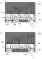
図4(a)は、静止画撮影モード内のジオラマ撮影モードにおける撮影待機画面400aを示す図である。撮影待機画面400aでは、AF枠401およびジオラマ枠設定移行ボタン402等がライブビュー画像に重畳して表示される。また、ライブビュー画像は、上下にぼかし効果が施されて表示される。なお、本実施形態においてはぼかしの効果をかけている領域を分かり易く示すためにライブビュー画像上をグレーで塗っているが、実際には、ぼかしの効果がかかっている領域であって、ライブビュー画像上にグレーの画像を重畳して表示はしない。ユーザはライブビュー画像を視認することで、ぼかし効果が施される位置(ぼかし位置)を認識することができる。ユーザがぼかし位置を変更したい場合にはジオラマ枠設定移行ボタン402をタッチする。ジオラマ枠設定移行ボタン402をタッチすることで、ジオラマ枠設定に移行し、図4(b)のジオラマ枠設定画面400bに遷移する。
Next, the diorama frame setting screen will be described.
FIG. 4A is a diagram showing a shooting standby screen 400a in the diorama shooting mode in the still image shooting mode. On the shooting standby screen 400a, the AF frame 401, the diorama frame setting transition button 402, and the like are superimposed and displayed on the live view image. In addition, the live view image is displayed with a blur effect applied up and down. In the present embodiment, the live view image is painted in gray in order to clearly show the area where the blurring effect is applied, but in reality, it is the area where the blurring effect is applied and the live performance is performed. The gray image is not superimposed on the view image and displayed. By visually recognizing the live view image, the user can recognize the position where the blur effect is applied (blurred position). If the user wants to change the blur position, touch the diorama frame setting transition button 402. By touching the diorama frame setting transition button 402, the transition to the diorama frame setting is performed, and the transition to the diorama frame setting screen 400b of FIG. 4 (b) is performed.

ジオラマ枠設定画面400bでは、AF枠401、ジオラマ枠403、矢印403a、確定ボタン404、リセットボタン405、縦横切替ボタン406がライブビュー画像に重畳して表示される。ジオラマ枠403は、枠外の領域(図中のグレー部分)にぼかし効果を施すことを示す枠である。矢印403aは、ジオラマ枠403が移動可能であることを示すアイテムである。確定ボタン404、リセットボタン405および縦横切替ボタン406は、所定のアイテムの一例に対応する。また、確定ボタン404、リセットボタン405および縦横切替ボタン406は、ユーザがタッチできるボタン(タッチボタン)である。
ユーザはジオラマ枠403をタッチパネル227a、十字キー108等を用いて移動させることができる。このとき、ジオラマ枠403の位置が変更されることに応じて、タッチボタンがジオラマ枠403と重ならないようにタッチボタンの位置が変更して表示される。なお、タッチボタンの位置が変更して表示される形態を、図5を参照して後述する。ユーザは確定ボタン404をタッチすることで、移動した位置にジオラマ枠403が設定される。その後、ジオラマ枠設定が終了し、続いてAF枠設定に移行して、図4(c)のAF枠設定画面400cに遷移する。
On the diorama frame setting screen 400b, the AF frame 401, the diorama frame 403, the arrow 403a, the confirmation button 404, the reset button 405, and the vertical / horizontal switching button 406 are superimposed and displayed on the live view image. The diorama frame 403 is a frame indicating that a blurring effect is applied to an area outside the frame (gray portion in the figure). The arrow 403a is an item indicating that the diorama frame 403 is movable. The confirm button 404, the reset button 405, and the vertical / horizontal switching button 406 correspond to an example of a predetermined item. Further, the confirmation button 404, the reset button 405, and the vertical / horizontal switching button 406 are buttons (touch buttons) that the user can touch.
The user can move the diorama frame 403 by using the touch panel 227a, the cross key 108, and the like. At this time, in response to the change in the position of the diorama frame 403, the position of the touch button is changed and displayed so that the touch button does not overlap with the diorama frame 403. The form in which the position of the touch button is changed and displayed will be described later with reference to FIG. By touching the confirmation button 404, the user sets the diorama frame 403 at the moved position. After that, the diorama frame setting is completed, and then the AF frame setting is started, and the AF frame setting screen 400c of FIG. 4C is displayed.

AF枠設定画面400cでは、AF枠401、確定ボタン407およびリセットボタン408がライブビュー画像に重畳して表示される。また、確定ボタン407およびリセットボタン408は、ユーザがタッチできるボタン(タッチボタン)である。
本実施形態では、ジオラマ枠設定から続けてAF枠設定に移行し、AF枠設定画面400cに遷移した直後では、確定ボタン407、リセットボタン408はAF枠401の位置に応じて表示位置が変更されない。すなわち、確定ボタン407、リセットボタン408はジオラマ枠の位置の設定を行っていたジオラマ枠設定画面400bにおいてジオラマ枠の位置が設定される直前に表示されていた位置のまま移動しない。一方、AF枠設定画面400cに遷移してから、ユーザによりAF枠401の位置が変更されると、確定ボタン407、リセットボタン408がAF枠401と重ならないように確定ボタン407等の位置が変更される。このような処理を、図6のフローチャートを参照して後述する。
ユーザは確定ボタン407をタッチすることで、移動した位置にAF枠が設定される。その後、AF枠設定が終了し、図4(a)の撮影待機画面400aに遷移する。
On the AF frame setting screen 400c, the AF frame 401, the confirmation button 407, and the reset button 408 are superimposed and displayed on the live view image. Further, the confirmation button 407 and the reset button 408 are buttons (touch buttons) that the user can touch.
In the present embodiment, the display positions of the confirmation button 407 and the reset button 408 are not changed according to the position of the AF frame 401 immediately after the diorama frame setting is continuously shifted to the AF frame setting and the AF frame setting screen 400c is displayed. .. That is, the confirm button 407 and the reset button 408 do not move at the positions displayed immediately before the position of the diorama frame is set on the diorama frame setting screen 400b in which the position of the diorama frame has been set. On the other hand, when the position of the AF frame 401 is changed by the user after the transition to the AF frame setting screen 400c, the positions of the confirmation button 407 and the confirmation button 407 are changed so that the confirmation button 407 and the reset button 408 do not overlap with the AF frame 401. Will be done. Such processing will be described later with reference to the flowchart of FIG.
By touching the confirmation button 407, the user sets the AF frame at the moved position. After that, the AF frame setting is completed, and the screen transitions to the shooting standby screen 400a of FIG. 4 (a).

次に、ジオラマ枠の位置に応じてタッチボタンの位置が変更して表示される場合の一例について図5(a)~(c)に示すジオラマ枠設定画面500a~500cを参照して説明する。
図5(a)~(c)は、ジオラマ枠設定に移行して表示されるジオラマ枠設定画面500a、500b、500cを示す図である。ジオラマ枠設定画面500a~cでは、AF枠401、ジオラマ枠403、矢印403a、確定ボタン404、リセットボタン405、縦横切替ボタン406、指標501が表示される。ここでは、AF枠401、ジオラマ枠403、確定ボタン404、リセットボタン405、縦横切替ボタン406は、図4(b)のジオラマ枠設定画面400bと同一の符号を付している。また、図5(a)~(c)のジオラマ枠設定画面500a~cでは、AF枠401が右上の角に近接した位置に表示されている。また、指標501は実際には非表示であってもよい。
Next, an example in which the position of the touch button is changed and displayed according to the position of the diorama frame will be described with reference to the diorama frame setting screens 500a to 500c shown in FIGS. 5A to 5C.
5 (a) to 5 (c) are diagrams showing the diorama frame setting screens 500a, 500b, and 500c displayed after shifting to the diorama frame setting. On the diorama frame setting screens 500a to c, the AF frame 401, the diorama frame 403, the arrow 403a, the confirmation button 404, the reset button 405, the vertical / horizontal switching button 406, and the index 501 are displayed. Here, the AF frame 401, the diorama frame 403, the confirmation button 404, the reset button 405, and the vertical / horizontal switching button 406 are designated by the same reference numerals as the diorama frame setting screen 400b of FIG. 4 (b). Further, in the diorama frame setting screens 500a to 500C of FIGS. 5A to 5C, the AF frame 401 is displayed at a position close to the upper right corner. Further, the index 501 may actually be hidden.

指標501は、ジオラマ枠403の中央に位置し、ジオラマ枠403の位置を示す。ここでは、指標501の位置を、ジオラマ枠設定画面500aの左上角を原点0として横方向をX軸、縦方向をY軸として表すものとする。
リセットボタン405は、ジオラマ枠403をリセットさせるタッチボタンである。ジオラマ枠403が図5(b)に示すように中央から変更された状態で、ユーザがリセットボタン405をタッチすることで、ジオラマ枠403が図5(a)に示すように表示部105の中央位置にジオラマ枠403が位置する初期位置に戻すことができる。図5(a)~(c)の縦横切替ボタン406は、ジオラマ枠403を、横(横長)から縦(縦長)あるいは縦から横に切り替えるタッチボタンである。ジオラマ枠403が図5(a)、(b)に示すように横の状態から、ユーザが縦横切替ボタン406をタッチすることで、図5(c)に示すように縦の状態に切り替わる。図5(a)、(b)の状態ではジオラマ枠403の上下にぼかし効果が施され、図5(c)の状態ではジオラマ枠403の左右にぼかし効果が施される。
なお、確定ボタン404、リセットボタン405および縦横切替ボタン406は、タッチボタンに限らず、何れのボタンを操作すればよいかをユーザにガイドするためのガイド表示用のアイテムであってもよい。
The index 501 is located in the center of the diorama frame 403 and indicates the position of the diorama frame 403. Here, it is assumed that the position of the index 501 is represented by the upper left corner of the diorama frame setting screen 500a as the origin 0, the horizontal direction as the X axis, and the vertical direction as the Y axis.
The reset button 405 is a touch button for resetting the diorama frame 403. When the user touches the reset button 405 in a state where the diorama frame 403 is changed from the center as shown in FIG. 5 (b), the diorama frame 403 is moved to the center of the display unit 105 as shown in FIG. 5 (a). It can be returned to the initial position where the diorama frame 403 is located at the position. The vertical / horizontal switching button 406 of FIGS. 5A to 5C is a touch button for switching the diorama frame 403 from horizontal (horizontal) to vertical (vertical) or vertical to horizontal. The diorama frame 403 switches from the horizontal state as shown in FIGS. 5 (a) and 5 (b) to the vertical state as shown in FIG. 5 (c) when the user touches the vertical / horizontal switching button 406. In the states of FIGS. 5A and 5B, the blurring effect is applied to the top and bottom of the diorama frame 403, and in the state of FIG. 5C, the blurring effect is applied to the left and right of the diorama frame 403.
The confirmation button 404, the reset button 405, and the vertical / horizontal switching button 406 are not limited to the touch buttons, and may be guide display items for guiding the user which button should be operated.

次に、AF枠の位置に応じてタッチボタンの位置を変更して表示する場合の一例について図5(d)~(f)に示すAF枠設定画面500d~500fを参照して説明する。
図5(d)~(f)は、AF枠設定に移行して表示されるAF枠設定画面500d、500e、500fを示す図である。AF枠設定画面500dでは、AF枠301、確定ボタン303、リセットボタン304、指標502が表示される。なお、AF枠301、確定ボタン303、リセットボタン304は、図3(b)のAF枠設定画面300bと同一の符号を付している。また、指標502は実際には非表示であってもよい。
Next, an example in which the position of the touch button is changed and displayed according to the position of the AF frame will be described with reference to the AF frame setting screens 500d to 500f shown in FIGS. 5 (d) to 5 (f).
5 (d) to 5 (f) are diagrams showing the AF frame setting screens 500d, 500e, and 500f displayed after shifting to the AF frame setting. On the AF frame setting screen 500d, the AF frame 301, the confirmation button 303, the reset button 304, and the index 502 are displayed. The AF frame 301, the confirmation button 303, and the reset button 304 have the same reference numerals as those of the AF frame setting screen 300b of FIG. 3 (b). Further, the index 502 may actually be hidden.

指標502は、AF枠301の中央に位置し、AF枠301の位置を示す。ここでは、指標502の位置を、AF枠設定画面500dの左上角を原点0として横方向をX軸、縦方向をY軸として表すものとする。
リセットボタン304は、AF枠301をリセットさせるタッチボタンである。AF枠301が図5(e)に示すように中央から変更された状態で、ユーザがリセットボタン304をタッチすることで、AF枠301が図5(d)に示すように表示部105の中央位置にAF枠301が位置する初期位置に戻すことができる。
なお、確定ボタン303およびリセットボタン304は、タッチボタンである場合に限られず、何れのボタンを操作すればよいかをユーザにガイドするためのガイド表示用のアイテムであってもよい。
The index 502 is located at the center of the AF frame 301 and indicates the position of the AF frame 301. Here, it is assumed that the position of the index 502 is represented by the origin 0 at the upper left corner of the AF frame setting screen 500d, the X axis in the horizontal direction, and the Y axis in the vertical direction.
The reset button 304 is a touch button that resets the AF frame 301. When the user touches the reset button 304 while the AF frame 301 is changed from the center as shown in FIG. 5 (e), the AF frame 301 is moved to the center of the display unit 105 as shown in FIG. 5 (d). It is possible to return to the initial position where the AF frame 301 is located at the position.
The confirmation button 303 and the reset button 304 are not limited to touch buttons, and may be guide display items for guiding the user which button should be operated.

次に、本実施形態のカメラ100の撮影処理の一例について図6のフローチャートを参照して説明する。図6のフローチャートは、システム制御部50が不揮発性メモリ222に格納されたプログラムをシステムメモリ223に展開して実行することにより実現される。なお、図6のフローチャートは、モード切替スイッチ103等により静止画撮影モードに切り替えられることで開始する。 Next, an example of the shooting process of the camera 100 of the present embodiment will be described with reference to the flowchart of FIG. The flowchart of FIG. 6 is realized by the system control unit 50 expanding the program stored in the non-volatile memory 222 into the system memory 223 and executing the program. The flowchart of FIG. 6 starts when the mode changeover switch 103 or the like is used to switch to the still image shooting mode.

S601では、システム制御部50は静止画撮影モード内でジオラマ撮影モードが設定されているか否かを判定する。ここでは、ジオラマ撮影モードではない場合を通常モードとする。ジオラマ撮影モードである場合にはS602に進み、通常モードの場合にはS640に進む。 In S601, the system control unit 50 determines whether or not the diorama shooting mode is set in the still image shooting mode. Here, the case where the mode is not the diorama shooting mode is set as the normal mode. In the case of the diorama shooting mode, the process proceeds to S602, and in the case of the normal mode, the process proceeds to S640.

S602では、システム制御部50はジオラマ撮影モードにおける撮影待機画面を表示する。ジオラマ撮影モードにおける撮影待機画面においてはライブビュー画像上に現在設定中のジオラマ枠とAF枠とを表示し、ジオラマ枠の外の領域の画像に対してぼかし効果を施して表示する。これにより、ユーザがぼかし効果がかかる領域とかからない領域とを認識することができる。また、S602においてはジオラマ枠設定移行ボタンをライブビュー画像に重畳して表示する。S602においては例えば図4(a)に示すジオラマ撮影モードにおける撮影待機画面400aを表示する。具体的には、システム制御部50はジオラマ枠、AF枠の指標の位置情報を不揮発性メモリ222から読み出し、読み出した情報に基づいてジオラマ枠、AF枠を表示する。不揮発性メモリ222には、予めジオラマ枠、AF枠の初期位置の位置情報が記憶されている。ただし、ユーザがジオラマ枠、AF枠を設定したことがある場合には、不揮発性メモリ222には前回、設定したジオラマ枠、AF枠の指標の位置情報が記憶されている。 In S602, the system control unit 50 displays a shooting standby screen in the diorama shooting mode. On the shooting standby screen in the diorama shooting mode, the currently set diorama frame and AF frame are displayed on the live view image, and the image in the area outside the diorama frame is displayed with a blur effect. As a result, the user can recognize the area where the blur effect is applied and the area where the blur effect is not applied. Further, in S602, the diorama frame setting transition button is superimposed and displayed on the live view image. In S602, for example, the shooting standby screen 400a in the diorama shooting mode shown in FIG. 4A is displayed. Specifically, the system control unit 50 reads the position information of the index of the diorama frame and the AF frame from the non-volatile memory 222, and displays the diorama frame and the AF frame based on the read information. The non-volatile memory 222 stores in advance the position information of the initial positions of the diorama frame and the AF frame. However, if the user has set the diorama frame and the AF frame, the non-volatile memory 222 stores the position information of the index of the previously set diorama frame and the AF frame.

S603では、システム制御部50はジオラマ枠設定を開始するか否かを判定する。ジオラマ枠設定は、図4(a)に示すジオラマ枠設定移行ボタン402をタッチすることにより、開始される。ジオラマ設定を開始する場合にはS604に進み、開始しない場合にはS635に進む。
S604では、システム制御部50はジオラマ枠設定画面を表示する。ジオラマ枠設定画面においては、ジオラマ枠の指標の位置情報に基づいてジオラマ枠を表示し、移動可能であることを示す矢印を表示する。S604においては、図4(b)に示すジオラマ枠設定画面400bに示すようにジオラマ枠403と共に矢印403aを表示する。
In S603, the system control unit 50 determines whether or not to start setting the diorama frame. The diorama frame setting is started by touching the diorama frame setting transition button 402 shown in FIG. 4 (a). If the diorama setting is started, the process proceeds to S604, and if not, the process proceeds to S635.
In S604, the system control unit 50 displays a diorama frame setting screen. On the diorama frame setting screen, the diorama frame is displayed based on the position information of the index of the diorama frame, and an arrow indicating that the diorama frame is movable is displayed. In S604, an arrow 403a is displayed together with the diorama frame 403 as shown in the diorama frame setting screen 400b shown in FIG. 4 (b).

S605では、システム制御部50はジオラマ枠の位置が閾値Th1よりも大きいか否かを判定する。この判定は、ジオラマ枠の設定画面に遷移し、未だジオラマ枠がユーザによって移動されていない場合のタッチボタンを表示する位置を決定するための判定である。ジオラマ枠の指標501(ジオラマ枠の中心)の位置情報が、閾値Th1よりも大きい場合、すなわち画面の下側の領域にジオラマ枠がある場合にはS607に進み、そうでない場合にはS606に進む。なお、ジオラマ枠が縦である場合には、ジオラマ枠の位置に関わらず、S605の判定はNoとなる。閾値Th1は、表示部105の中央より下側に位置している。これは、最初にジオラマ枠を移動する画面に遷移した場合には、表示部105の下側(Y=0の反対側)にタッチアイテムが表示されるようにするためである。図4(a)に示すように、S605より前の画面においては、タッチボタンやアイテムは表示部105の下側に表示されているため、画面の遷移後もアイテムが下側に表示されるようにするため、閾値を設定している。しかし、ジオラマ枠は表示部105の下側にも移動可能なので、その場合には、ジオラマ枠を移動するためのタッチと、タッチボタンへのタッチとを区別するため、また、視認性を向上するために、タッチボタンを表示部105の上側に表示するようにする。このように、ユーザの操作性と視認性とを共に保つために閾値Th1がS605において適用される。 In S605, the system control unit 50 determines whether or not the position of the diorama frame is larger than the threshold value Th1. This determination is a determination for transitioning to the setting screen of the diorama frame and determining the position to display the touch button when the diorama frame has not been moved by the user yet. If the position information of the index 501 (center of the diorama frame) of the diorama frame is larger than the threshold value Th1, that is, if the diorama frame is in the lower area of the screen, the process proceeds to S607, otherwise the process proceeds to S606. .. When the diorama frame is vertical, the determination of S605 is No regardless of the position of the diorama frame. The threshold value Th1 is located below the center of the display unit 105. This is so that the touch item is displayed on the lower side (opposite side of Y = 0) of the display unit 105 when the screen for moving the diorama frame is first displayed. As shown in FIG. 4A, since the touch buttons and items are displayed on the lower side of the display unit 105 on the screen before S605, the items are displayed on the lower side even after the screen transition. In order to make it, the threshold value is set. However, since the diorama frame can also be moved to the lower side of the display unit 105, in that case, in order to distinguish between the touch for moving the diorama frame and the touch to the touch button, the visibility is improved. Therefore, the touch button is displayed on the upper side of the display unit 105. In this way, the threshold Th1 is applied in S605 in order to maintain both the user's operability and visibility.

S606では、システム制御部50はタッチボタンを画面の下部に配置し、タッチボタンの位置が下部である旨の情報をシステムメモリ223に記憶する。S606においては、図5(a)に示すように、確定ボタン404、リセットボタン405、縦横切替ボタン406(タッチボタン)を画面の下部に、下辺に沿って配置する。また、図5(c)に示すように、ジオラマ枠403が縦の場合には、指標501が常に閾値Th1よりも上に位置するために、確定ボタン404、リセットボタン405および縦横切替ボタン406は、図5(c)の状態のままであって変更されない。
S607では、システム制御部50はタッチボタンを画面の上部に配置し、タッチボタンの位置が上部である旨の情報をシステムメモリ223に記憶する。S607においては、図5(b)に示すように、確定ボタン404、リセットボタン405、縦横切替ボタン406(タッチボタン)を画面の上部に、上辺に沿って配置する。
In S606, the system control unit 50 arranges the touch button at the lower part of the screen, and stores the information that the position of the touch button is at the lower part in the system memory 223. In S606, as shown in FIG. 5A, a confirmation button 404, a reset button 405, and a vertical / horizontal switching button 406 (touch button) are arranged at the lower part of the screen along the lower side. Further, as shown in FIG. 5C, when the diorama frame 403 is vertical, the index 501 is always located above the threshold value Th1, so that the confirmation button 404, the reset button 405, and the vertical / horizontal switching button 406 are used. , The state shown in FIG. 5 (c) remains unchanged.
In S607, the system control unit 50 arranges the touch button at the upper part of the screen, and stores the information that the position of the touch button is at the upper part in the system memory 223. In S607, as shown in FIG. 5B, a confirmation button 404, a reset button 405, and a vertical / horizontal switching button 406 (touch button) are arranged at the upper part of the screen along the upper side.

次のS608からS621まではジオラマ枠設定画面でのユーザの操作に伴う処理である。
S608では、システム制御部50はジオラマ枠の位置を確定する操作があったか否かを判定する。例えば、ユーザは操作部227のSETボタンを用いたり、図5(a)~(c)に示す確定ボタン404をタッチしたりすることにより、ジオラマ枠の位置を確定する操作を行う。ジオラマ枠の位置を確定する操作があった場合にはS622に進み、操作がない場合にはS609に進む。
The following S608 to S621 are processes associated with the user's operation on the diorama frame setting screen.
In S608, the system control unit 50 determines whether or not there has been an operation for determining the position of the diorama frame. For example, the user performs an operation of confirming the position of the diorama frame by using the SET button of the operation unit 227 or touching the confirmation button 404 shown in FIGS. 5A to 5C. If there is an operation to determine the position of the diorama frame, the process proceeds to S622, and if there is no operation, the process proceeds to S609.

S609では、システム制御部50はジオラマ枠を移動する操作があったか否かを判定する。例えば、ユーザは操作部227の十字キーを用いてジオラマ枠を移動させたり、タッチパネル227aを用いて移動させたい位置を直接タッチしたりすることにより、ジオラマ枠を移動させる操作を行う。ジオラマ枠を移動させる操作があった場合にはS610に進み、操作がない場合にはS617に進む。
S610では、システム制御部50はジオラマ枠を移動する操作に応じてジオラマ枠を移動し、ぼかし効果を施す位置を変更する。なお、システム制御部50はジオラマ枠の移動に応じてジオラマ枠の指標の位置情報を逐次、システムメモリ223に記憶する。
In S609, the system control unit 50 determines whether or not there has been an operation to move the diorama frame. For example, the user performs an operation of moving the diorama frame by moving the diorama frame using the cross key of the operation unit 227 or by directly touching the position to be moved using the touch panel 227a. If there is an operation to move the diorama frame, the process proceeds to S610, and if there is no operation, the process proceeds to S617.
In S610, the system control unit 50 moves the diorama frame according to the operation of moving the diorama frame, and changes the position where the blur effect is applied. The system control unit 50 sequentially stores the position information of the index of the diorama frame in the system memory 223 according to the movement of the diorama frame.

S611では、システム制御部50はジオラマ枠が縦であるか否かを判定する。なお、ジオラマ枠が縦である場合にはタッチボタンの位置を変更しないため、S612以降のタッチボタンの表示位置を変更する処理を行わない。ジオラマ枠が縦である場合にはS608に戻り、縦ではない場合にはS612に進む。
S612では、システム制御部50はタッチボタンが画面の上部に配置されているか否かを、システムメモリ223に記憶された情報に基づいて判定する。タッチボタンが画面の上部に配置されている場合にはS613に進み、上部に配置されていない場合にはS615に進む。
In S611, the system control unit 50 determines whether or not the diorama frame is vertical. Since the position of the touch button is not changed when the diorama frame is vertical, the process of changing the display position of the touch button after S612 is not performed. If the diorama frame is vertical, the process returns to S608, and if the diorama frame is not vertical, the process proceeds to S612.
In S612, the system control unit 50 determines whether or not the touch button is arranged at the upper part of the screen based on the information stored in the system memory 223. If the touch button is arranged at the upper part of the screen, the process proceeds to S613, and if the touch button is not arranged at the upper part, the process proceeds to S615.

S613では、システム制御部50はジオラマ枠の位置が閾値Th2よりも小さいか否かを判定する。具体的には、システム制御部50はジオラマ枠の指標の位置情報と、予め不揮発性メモリ222に記憶された閾値Th2とに基づいて判定する。ジオラマ枠の位置が閾値Th2よりも小さい場合、すなわちジオラマ枠の位置が表示部105のY軸方向の中央の位置にある閾値Th2よりも上に位置する場合にはS614に進み、閾値Th2よりも大きい場合にはタッチボタンを移動せずにS608に戻る。なお、閾値はY座標方向においてTh1≧Th2の関係である。
S614では、システム制御部50はタッチボタンを画面の下部に配置し、タッチボタンの位置が下部である旨の情報をシステムメモリ223に記憶する。
In S613, the system control unit 50 determines whether or not the position of the diorama frame is smaller than the threshold value Th2. Specifically, the system control unit 50 determines based on the position information of the index of the diorama frame and the threshold value Th2 previously stored in the non-volatile memory 222. If the position of the diorama frame is smaller than the threshold value Th2, that is, if the position of the diorama frame is located above the threshold value Th2 at the center position in the Y-axis direction of the display unit 105, the process proceeds to S614 and the position is higher than the threshold value Th2. If it is large, the process returns to S608 without moving the touch button. The threshold value has a relationship of Th1 ≧ Th2 in the Y coordinate direction.
In S614, the system control unit 50 arranges the touch button at the lower part of the screen, and stores the information that the position of the touch button is at the lower part in the system memory 223.

S615では、システム制御部50はジオラマ枠の位置が閾値Th1よりも大きいか否かを判定する。具体的には、システム制御部50はジオラマ枠の指標の位置情報と、予め不揮発性メモリ222に記憶された閾値Th1とに基づいて判定する。ジオラマ枠の位置が閾値Th1よりも大きい場合、すなわちジオラマ枠の位置が表示部105の下側の位置にある閾値Th1よりも下に位置する場合にはS616に進み、閾値Th1よりも大きくない場合にはタッチボタンを移動せずにS608に戻る。
S616では、システム制御部50はタッチボタンを画面の上部に配置し、タッチボタンの位置が上部である旨の情報をシステムメモリ223に記憶する。
In S615, the system control unit 50 determines whether or not the position of the diorama frame is larger than the threshold value Th1. Specifically, the system control unit 50 determines based on the position information of the index of the diorama frame and the threshold value Th1 stored in advance in the non-volatile memory 222. When the position of the diorama frame is larger than the threshold value Th1, that is, when the position of the diorama frame is located below the threshold value Th1 at the lower position of the display unit 105, the process proceeds to S616, and when the position is not larger than the threshold value Th1. Return to S608 without moving the touch button.
In S616, the system control unit 50 arranges the touch button at the upper part of the screen, and stores the information that the position of the touch button is at the upper part in the system memory 223.

S612~S616においては、タッチボタンが下側に表示されることの方が割合として多くなるようにしている。S612においてタッチボタンが上側にもともと表示されていると判定した場合には、S613において、現在の(移動された)ジオラマ枠の位置が表示部105の中央の位置である閾値Th2よりも小さければタッチボタンを下側に移動するとしている。つまり、タッチボタンがもともと上側に表示されていた場合には、画面の半分から上にジオラマ枠が位置するとタッチボタンが下側に移動し、画面の半分から下にジオラマ枠が位置するとタッチボタンが上側のままとなる。よって、上側から下側へタッチボタンが移動する割合はジオラマ枠の移動可能範囲に対して半分となる。 In S612 to S616, the number of touch buttons displayed on the lower side is increased as a percentage. When it is determined in S612 that the touch button is originally displayed on the upper side, in S613, if the position of the current (moved) diorama frame is smaller than the threshold value Th2 which is the center position of the display unit 105, touch. The button is supposed to be moved down. In other words, if the touch button was originally displayed on the upper side, the touch button will move to the lower side when the diorama frame is located above half of the screen, and the touch button will move when the diorama frame is located below half of the screen. It remains on the upper side. Therefore, the ratio of the touch button moving from the upper side to the lower side is half of the movable range of the diorama frame.

一方で、もともとジオラマ枠が下側に表示されていた場合には、S615において、現在の(移動された)ジオラマ枠の位置が表示部105の下側よりの位置である閾値Th1よりも大きければタッチボタンを上側に移動するとしている。つまり、タッチボタンがもともと下側に表示されていた場合には、画面の半分よりさらに狭い範囲にジオラマ枠が移動しないと、タッチボタンは上側に移動しない。表示部105のY軸方向の長さをYYとすると、Th1の方が(YY-Th1)よりも長くなる。よって、タッチボタンが下側から上側へ移動する割合はジオラマ枠の移動可能範囲に対して(YY-Th1)/YY、半分よりも低い割合で移動する。つまり、ジオラマ枠を移動した際に、タッチボタンは下側に表示されたままになる割合の方が高くなる。 On the other hand, when the diorama frame is originally displayed on the lower side, in S615, if the position of the current (moved) diorama frame is larger than the threshold value Th1 which is the position from the lower side of the display unit 105. The touch button is supposed to be moved upward. In other words, if the touch button was originally displayed on the lower side, the touch button will not move on the upper side unless the diorama frame moves to a range narrower than half of the screen. Assuming that the length of the display unit 105 in the Y-axis direction is YY, Th1 is longer than (YY-Th1). Therefore, the rate at which the touch button moves from the lower side to the upper side is (YY-Th1) / YY with respect to the movable range of the diorama frame, and moves at a rate lower than half. That is, when the diorama frame is moved, the proportion of the touch button that remains displayed at the bottom is higher.

また、タッチボタンが上側に移動するジオラマ枠の範囲は、Th1≦y≦YY(=画面の半分未満)なのに対して、タッチボタンが下側に移動するジオラマ枠の範囲は、0≦y≦Th2(=画面の半分)となる。このように、タッチボタンが下側に表示されやすくすることで、図4(a)のようなジオラマ枠設定の処理に入る前の画面と同じように下側にタッチボタンが表示されやすくなり、視認性と操作性が向上する。また、タッチボタンが下側に表示される割合が大きくなると、表示部105を下側から支えて持つユーザがタッチボタンへのタッチを行う際に、表示部105の下側から上側に指(手)を伸ばさなくてもタッチをすることができる。よって、タッチ操作を行う指(手)によって、画像が隠れてしまう割合を低減することができる。 Further, the range of the diorama frame in which the touch button moves upward is Th1 ≦ y ≦ YY (= less than half of the screen), whereas the range of the diorama frame in which the touch button moves downward is 0 ≦ y ≦ Th2. (= Half of the screen). By making it easier for the touch button to be displayed on the lower side in this way, it becomes easier for the touch button to be displayed on the lower side as in the screen before entering the diorama frame setting process as shown in FIG. 4 (a). Visibility and operability are improved. Further, when the ratio of the touch button being displayed on the lower side becomes large, when the user who supports and holds the display unit 105 from the lower side touches the touch button, a finger (hand) from the lower side to the upper side of the display unit 105. ) Can be touched without stretching. Therefore, it is possible to reduce the rate at which the image is hidden by the finger (hand) that performs the touch operation.

S617では、システム制御部50はジオラマ枠をリセットする操作があったか否かを判定する。例えば、ユーザは図5(a)に示すリセットボタン405をタッチすること等により、ジオラマ枠をリセットする操作を行うことができる。ジオラマ枠をリセットする操作があった場合にはS618に進み、操作がない場合にはS619に進む。
S618では、システム制御部50はジオラマ枠をリセットして、初期位置である中央の位置に戻す。その後、S606に戻る。
In S617, the system control unit 50 determines whether or not there has been an operation to reset the diorama frame. For example, the user can perform an operation of resetting the diorama frame by touching the reset button 405 shown in FIG. 5A. If there is an operation to reset the diorama frame, the process proceeds to S618, and if there is no operation, the process proceeds to S619.
In S618, the system control unit 50 resets the diorama frame and returns it to the central position, which is the initial position. After that, it returns to S606.

S619では、システム制御部50はジオラマ枠の縦横を切り替える操作があったか否かを判定する。例えば、ユーザは操作部227を用いたり、図5(a)に示す縦横切替ボタン406をタッチしたりすることにより、ジオラマ枠の縦横を切り替える操作を行う。ジオラマ枠の縦横を切り替える操作があった場合にはS620に進み、操作がない場合にはS608に戻る。
S620では、システム制御部50はジオラマ枠の縦横を横から縦あるいは縦から横に切り替える。システム制御部50は切り替えたジオラマ枠に応じてぼかし効果を施す位置を変更する。なお、システム制御部50はジオラマ枠の縦横の切り替えに応じてジオラマ枠が縦であるか横であるかの情報を逐次、システムメモリ223に更新する。
S621では、システム制御部50はジオラマ枠が横であるか否かを判定する。横である場合にはS612に進む。一方、横ではない場合、すなわち縦の場合にはS606に戻る。
In S619, the system control unit 50 determines whether or not there has been an operation of switching the vertical and horizontal directions of the diorama frame. For example, the user performs an operation of switching the vertical / horizontal of the diorama frame by using the operation unit 227 or touching the vertical / horizontal switching button 406 shown in FIG. 5A. If there is an operation to switch the vertical and horizontal of the diorama frame, the process proceeds to S620, and if there is no operation, the process returns to S608.
In S620, the system control unit 50 switches the vertical and horizontal of the diorama frame from horizontal to vertical or from vertical to horizontal. The system control unit 50 changes the position where the blur effect is applied according to the switched diorama frame. The system control unit 50 sequentially updates the information on whether the diorama frame is vertical or horizontal to the system memory 223 according to the vertical / horizontal switching of the diorama frame.
In S621, the system control unit 50 determines whether or not the diorama frame is horizontal. If it is horizontal, proceed to S612. On the other hand, if it is not horizontal, that is, if it is vertical, it returns to S606.

次に、S622以降の処理について説明する。
S622は上述したS608においてジオラマ枠の位置が確定された後の処理である。S622では、システム制御部50はAF枠設定画面を表示する。すなわち、本実施形態ではジオラマ撮影モードが設定されている場合、ジオラマ枠設定に続いてAF枠設定に移行する。ここでは、システム制御部50は確定したジオラマ枠を表示すると共に、S602において表示したAF枠を継続して表示する。
Next, the processing after S622 will be described.
S622 is a process after the position of the diorama frame is determined in S608 described above. In S622, the system control unit 50 displays the AF frame setting screen. That is, in the present embodiment, when the diorama shooting mode is set, the process shifts to the AF frame setting following the diorama frame setting. Here, the system control unit 50 displays the fixed diorama frame and continuously displays the AF frame displayed in S602.

S623では、システム制御部50は、確定ボタン(タッチボタン)をAF枠の位置に関わらず、システムメモリ223に記憶されているタッチボタンの表示位置に表示する。すなわち、S606、S607、S614、S616のいずれかの最新の処理においてシステムメモリ223に記憶されたタッチボタンの表示位置に確定ボタンを表示する。S602においてAF枠が表示された位置が、中央の位置ではない、ユーザが前に設定した位置、つまり表示部105の上側もしくは下側によった位置である場合があるが、S623においてはAF枠の位置に関わらずタッチボタンの表示位置を決定する。 In S623, the system control unit 50 displays the confirmation button (touch button) at the display position of the touch button stored in the system memory 223 regardless of the position of the AF frame. That is, the confirmation button is displayed at the display position of the touch button stored in the system memory 223 in the latest processing of any one of S606, S607, S614, and S616. In S602, the position where the AF frame is displayed may not be the center position, but the position set before by the user, that is, the position depending on the upper side or the lower side of the display unit 105, but in S623, the AF frame is displayed. Determines the display position of the touch button regardless of the position of.

ここで、図7を参照して、ジオラマ枠設定画面からAF枠設定画面に遷移した場合の一例について説明する。図7(a)は、ジオラマ枠設定画面700aの一例を示す図である。
ジオラマ枠設定画面700aでは、ジオラマ枠403の指標409(Y軸方向の中心位置)が閾値Th1よりも小さいことから、タッチボタンが画面の下部に配置されている。ここで、ユーザがジオラマ枠403の位置を確定させるために、確定ボタン404をタッチすると(S608の判定をYes)、AF枠設定画面に遷移する(S622)。
Here, an example of a transition from the diorama frame setting screen to the AF frame setting screen will be described with reference to FIG. 7. FIG. 7A is a diagram showing an example of the diorama frame setting screen 700a.
On the diorama frame setting screen 700a, since the index 409 (center position in the Y-axis direction) of the diorama frame 403 is smaller than the threshold value Th1, the touch button is arranged at the lower part of the screen. Here, when the user touches the confirmation button 404 in order to confirm the position of the diorama frame 403 (determination of S608 is Yes), the screen transitions to the AF frame setting screen (S622).

図7(b)は、AF枠設定画面700bの一例を示す図である(S622、S623)。
AF枠設定画面700bは、図7(a)に示すジオラマ枠設定画面700aにおいてジオラマ枠を確定する操作に応じて遷移した直後に表示される画面である。ここでは、AF枠401の指標410(Y軸方向の中心位置)が閾値Th1よりも大きいが、確定ボタン407が画面の下部に配置されている。S608において確定操作がされた後、S623においては、AF枠設定画面700bの確定ボタン407が、図7(a)のジオラマ枠設定画面700aの確定ボタン404と同じ位置に表示される。このように、AF枠設定に移行した直後に確定ボタン407をジオラマ枠設定のときの確定ボタン404と同じ位置に表示する。したがって、ユーザはジオラマ枠の確定操作(確定ボタンのタッチ)をした後、続けて同じ位置をタッチすればAF枠の確定(確定ボタンのタッチ)をすることができる。すなわち、ユーザがAF枠401の位置を変更する必要がなく、直ぐにAF枠401の位置を確定させたい場合には、即座に確定ボタン407をタッチすることができる。例えば、AF枠設定に移行した直後に、ユーザがAF枠401の位置を変更する必要がない場合を想定する。この場合、AF枠401の位置に応じて確定ボタン407の位置を決定すると、直前のジオラマ枠設定画面における確定ボタンの表示位置と異なる位置にAF枠設定画面における確定ボタンが表示される可能性がある。AF枠の位置をこのまま変えずに確定しようとしているユーザは、後述するS624のAF枠の位置を確定する操作を素早く行いたい。したがって、確定ボタンの表示位置が変わってしまうと、ユーザは再び確定ボタンを探し、タッチする指の位置を変えるために指を移動する操作が必要となる。S623のように、直前のジオラマ枠設定画面における確定ボタンの表示位置から確定ボタンの表示位置を変えないようにすることで、ユーザは同じ位置を2回タッチすれば、素早くジオラマ枠の設定とAF枠の設定を行うことができる。また、ユーザが確定ボタンの表示位置がジオラマ枠設定画面における表示位置と認識している場合に、AF枠の設定画面に遷移したことに応じて確定ボタンの表示位置が移動すると、ユーザが確定ボタンの表示されていない位置をタッチしてしまう可能性がある。確定ボタンの表示されていないライブビュー画像上をタッチするとAF枠がタッチした位置であり、ユーザの意図しない位置へと移動してしまうことになる。一方、S623のように確定ボタンの表示位置を変えないようにすることでユーザの意図しない位置にAF枠が移動してしまう可能性を低減することができる。
なお、ユーザがAF枠401の位置を変更したい場合にはS624以降の処理にて行うことができる。
FIG. 7B is a diagram showing an example of the AF frame setting screen 700b (S622, S623).
The AF frame setting screen 700b is a screen displayed immediately after the transition in response to the operation of determining the diorama frame on the diorama frame setting screen 700a shown in FIG. 7A. Here, the index 410 (center position in the Y-axis direction) of the AF frame 401 is larger than the threshold value Th1, but the confirmation button 407 is arranged at the bottom of the screen. After the confirmation operation is performed in S608, in S623, the confirmation button 407 of the AF frame setting screen 700b is displayed at the same position as the confirmation button 404 of the diorama frame setting screen 700a of FIG. 7A. In this way, immediately after shifting to the AF frame setting, the confirmation button 407 is displayed at the same position as the confirmation button 404 when the diorama frame is set. Therefore, the user can confirm the AF frame (touch the confirmation button) by continuously touching the same position after performing the confirmation operation of the diorama frame (touching the confirmation button). That is, if the user does not need to change the position of the AF frame 401 and wants to immediately confirm the position of the AF frame 401, he / she can immediately touch the confirmation button 407. For example, it is assumed that the user does not need to change the position of the AF frame 401 immediately after shifting to the AF frame setting. In this case, if the position of the confirmation button 407 is determined according to the position of the AF frame 401, the confirmation button on the AF frame setting screen may be displayed at a position different from the display position of the confirmation button on the immediately preceding diorama frame setting screen. be. A user who is trying to determine the position of the AF frame without changing it as it is wants to quickly perform an operation for determining the position of the AF frame of S624, which will be described later. Therefore, when the display position of the confirmation button changes, the user needs to search for the confirmation button again and move the finger to change the position of the finger to be touched. By not changing the display position of the confirmation button from the display position of the confirmation button on the previous diorama frame setting screen as in S623, the user can quickly set the diorama frame and AF by touching the same position twice. You can set the frame. In addition, when the user recognizes that the display position of the confirmation button is the display position on the diorama frame setting screen, and the display position of the confirmation button moves in response to the transition to the AF frame setting screen, the user confirms the button. There is a possibility of touching a position that is not displayed. If you touch on the live view image where the confirmation button is not displayed, the AF frame is at the touched position, and the AF frame will move to a position not intended by the user. On the other hand, by not changing the display position of the confirmation button as in S623, the possibility that the AF frame moves to a position not intended by the user can be reduced.
If the user wants to change the position of the AF frame 401, it can be performed in the process after S624.

以下、図6のフローチャートに戻りS624以降の処理について説明する。
次のS624からS633まではAF枠設定画面でのユーザの操作に伴う処理である。
S624では、システム制御部50はAF枠の位置を確定する操作があったか否かを判定する。例えば、ユーザは操作部227のSETボタンを用いたり、図7(b)に示す確定ボタン407をタッチしたりすることにより、AF枠の位置を確定する操作を行う。AF枠の位置を確定する操作があった場合にはS634に進み、操作がない場合にはS625に進む。
Hereinafter, the process after S624 will be described by returning to the flowchart of FIG.
The following steps from S624 to S633 are processes associated with the user's operation on the AF frame setting screen.
In S624, the system control unit 50 determines whether or not there has been an operation for determining the position of the AF frame. For example, the user performs an operation of confirming the position of the AF frame by using the SET button of the operation unit 227 or touching the confirmation button 407 shown in FIG. 7B. If there is an operation to determine the position of the AF frame, the process proceeds to S634, and if there is no operation, the process proceeds to S625.

S625では、システム制御部50はAF枠を移動する操作があったか否かを判定する。例えば、ユーザは操作部227の十字キーを用いてAF枠を移動させたり、タッチパネル227aを用いて移動させたい位置を直接タッチしたりすることにより、AF枠を移動させる操作を行う。AF枠を移動させる操作があった場合にはS626に進み、操作がない場合にはS632に進む。
S626では、システム制御部50はAF枠を移動する操作に応じてAF枠を移動する。なお、システム制御部50はAF枠の移動に応じてAF枠の指標の位置情報を逐次、システムメモリ223に記憶する。
In S625, the system control unit 50 determines whether or not there is an operation of moving the AF frame. For example, the user performs an operation of moving the AF frame by moving the AF frame using the cross key of the operation unit 227 or by directly touching the position to be moved using the touch panel 227a. If there is an operation to move the AF frame, the process proceeds to S626, and if there is no operation, the process proceeds to S632.
In S626, the system control unit 50 moves the AF frame according to the operation of moving the AF frame. The system control unit 50 sequentially stores the position information of the index of the AF frame in the system memory 223 according to the movement of the AF frame.

S627では、システム制御部50はタッチボタンが画面の上部に配置されているか否かを、システムメモリ223に記憶された情報に基づいて判定する。タッチボタンが画面の上部に配置されている場合にはS628に進み、上部に配置されていない場合にはS630に進む。
S628では、システム制御部50はAF枠の位置が閾値Th2よりも小さいか否かを判定する。具体的には、システム制御部50はAF枠の指標の位置情報と、予め不揮発性メモリ222に記憶された閾値Th2とに基づいて判定する。AF枠の位置が閾値Th2よりも小さい場合、すなわちAF枠の位置が表示部105のY軸方向の中央の位置にある閾値Th2よりも上に位置する場合にはS629に進み、閾値Th2よりも大きい場合にはタッチボタンを移動せずにS624に戻る。
S629では、システム制御部50はタッチボタンを画面の下部に配置し、タッチボタンの位置が下部である旨の情報をシステムメモリ223に記憶する。
In S627, the system control unit 50 determines whether or not the touch button is arranged at the upper part of the screen based on the information stored in the system memory 223. If the touch button is arranged at the upper part of the screen, the process proceeds to S628, and if the touch button is not arranged at the upper part, the process proceeds to S630.
In S628, the system control unit 50 determines whether or not the position of the AF frame is smaller than the threshold value Th2. Specifically, the system control unit 50 determines based on the position information of the index of the AF frame and the threshold value Th2 previously stored in the non-volatile memory 222. If the position of the AF frame is smaller than the threshold value Th2, that is, if the position of the AF frame is located above the threshold value Th2 at the center position in the Y-axis direction of the display unit 105, the process proceeds to S629 and is higher than the threshold value Th2. If it is large, the process returns to S624 without moving the touch button.
In S629, the system control unit 50 arranges the touch button at the lower part of the screen, and stores the information that the position of the touch button is at the lower part in the system memory 223.

S630では、システム制御部50はAF枠の位置が閾値Th1よりも大きいか否かを判定する。具体的には、システム制御部50はAF枠の指標の位置情報と、予め不揮発性メモリ222に記憶された閾値Th1とに基づいて判定する。AF枠の位置が閾値Th1よりも大きい場合、すなわちAF枠の位置が表示部105の下側の位置にある閾値Th1よりも下に位置する場合にはS631に進み、閾値Th1よりも大きくない場合にはタッチボタンを移動せずにS624に戻る。
S631では、システム制御部50はタッチボタンを画面の上部に配置し、タッチボタンの位置が上部である旨の情報をシステムメモリ223に記憶する。
S627~S631においては、S612~S616と同様にタッチボタンが下側に表示されることの方が割合として多くなるようにしている。
In S630, the system control unit 50 determines whether or not the position of the AF frame is larger than the threshold value Th1. Specifically, the system control unit 50 determines based on the position information of the index of the AF frame and the threshold value Th1 stored in advance in the non-volatile memory 222. When the position of the AF frame is larger than the threshold value Th1, that is, when the position of the AF frame is located below the threshold value Th1 at the lower position of the display unit 105, the process proceeds to S631 and when the position is not larger than the threshold value Th1. Return to S624 without moving the touch button.
In S631, the system control unit 50 arranges the touch button at the upper part of the screen, and stores the information that the position of the touch button is at the upper part in the system memory 223.
In S627 to S631, as in S612 to S616, the number of touch buttons displayed on the lower side is increased as a percentage.

S632では、システム制御部50はAF枠をリセットする操作があったか否かを判定する。例えば、ユーザは図7(b)に示すリセットボタン408をタッチすることにより、AF枠をリセットする操作を行うことができる。AF枠をリセットする操作があった場合にはS633に進み、操作がない場合にはS624に戻る。
S633では、システム制御部50はAF枠をリセットして、初期位置である中央の位置に戻す。その後、S627に進む。
In S632, the system control unit 50 determines whether or not there has been an operation to reset the AF frame. For example, the user can perform an operation of resetting the AF frame by touching the reset button 408 shown in FIG. 7 (b). If there is an operation to reset the AF frame, the process proceeds to S633, and if there is no operation, the process returns to S624.
In S633, the system control unit 50 resets the AF frame and returns it to the central position, which is the initial position. After that, the process proceeds to S627.

S634では、システム制御部50はAF枠設定画面を終了し、ジオラマ枠撮影モードにおける撮影待機画面を表示する。S634においては、S602と同様に図4(a)に示すような画面が表示される。また、S634においては、システム制御部50はS624におけるAF枠の確定操作に応じて、ジオラマ枠の指標の位置情報、ジオラマ枠が縦であるか横であるかの情報、AF枠の指標の位置情報を不揮発性メモリ222に記憶する。
S635では、システム制御部50は撮影準備指示があったか否かを判定する。撮影準備指示は、ユーザがシャッターボタン101を半押しし、第1シャッタースイッチ225がオンになることによって実行される。撮影準備指示があった場合にはS636に進み、撮影準備指示がない場合にはS601に戻る。
In S634, the system control unit 50 ends the AF frame setting screen and displays the shooting standby screen in the diorama frame shooting mode. In S634, the screen as shown in FIG. 4A is displayed as in S602. Further, in S634, the system control unit 50 receives the position information of the index of the diorama frame, the information of whether the diorama frame is vertical or horizontal, and the position of the index of the AF frame according to the confirmation operation of the AF frame in S624. Information is stored in the non-volatile memory 222.
In S635, the system control unit 50 determines whether or not there is a shooting preparation instruction. The shooting preparation instruction is executed when the user presses the shutter button 101 halfway and the first shutter switch 225 is turned on. If there is a shooting preparation instruction, the process proceeds to S636, and if there is no shooting preparation instruction, the process returns to S601.

S636では、システム制御部50は設定されたAF枠の位置に基づいてAF処理を開始する。
S637では、システム制御部50は撮影指示があったか否かを判定する。ユーザがシャッターボタン101を全押しし、第2シャッタースイッチ226がオンになると撮影指示が実行される。撮影指示があった場合にはS638に進み、撮影指示がない場合にはS635に戻る。
S638では、システム制御部50は撮影処理を開始する。
S639では、システム制御部50は画像データを記録媒体240に記録する記録処理を行う。なお、ジオラマ枠が設定されている場合、システム制御部50は設定されたジオラマ枠の位置に応じてぼかし効果を施す。
In S636, the system control unit 50 starts the AF process based on the position of the set AF frame.
In S637, the system control unit 50 determines whether or not there is a shooting instruction. When the user fully presses the shutter button 101 and the second shutter switch 226 is turned on, a shooting instruction is executed. If there is a shooting instruction, the process proceeds to S638, and if there is no shooting instruction, the process returns to S635.
In S638, the system control unit 50 starts the shooting process.
In S639, the system control unit 50 performs a recording process of recording image data on the recording medium 240. When the diorama frame is set, the system control unit 50 applies a blur effect according to the position of the set diorama frame.

上述したS601において通常モードが設定されている場合にはS640に進む。
S640では、システム制御部50は通常モードにおける撮影待機画面を表示する。また、システム制御部50はAF枠をライブビュー画像に重畳して表示する。具体的には、システム制御部50はAF枠の指標の位置情報を不揮発性メモリ222から読み出し、読み出した情報に基づいてAF枠を表示する。不揮発性メモリ222には、予めAF枠の初期位置の情報が記憶されている。ただし、ユーザがAF枠を設定したことがある場合には、不揮発性メモリ222には前回、設定したAF枠の指標の位置情報が記憶されている。例えば、システム制御部50は図3(a)に示す通常モードにおける撮影待機画面300aを表示する。
If the normal mode is set in S601 described above, the process proceeds to S640.
In S640, the system control unit 50 displays a shooting standby screen in the normal mode. Further, the system control unit 50 superimposes the AF frame on the live view image and displays it. Specifically, the system control unit 50 reads the position information of the index of the AF frame from the non-volatile memory 222, and displays the AF frame based on the read information. Information on the initial position of the AF frame is stored in advance in the non-volatile memory 222. However, if the user has set the AF frame, the non-volatile memory 222 stores the position information of the index of the AF frame that was set last time. For example, the system control unit 50 displays the shooting standby screen 300a in the normal mode shown in FIG. 3A.

S641では、システム制御部50はAF枠設定を開始するか否かを判定する。例えば、ユーザは図3(a)に示すAF枠設定移行ボタン302をタッチすることにより、AF枠設定の開始を指示する。AF枠設定を開始する場合にはS642に進み、開始しない場合にはS635に進む。
S642では、システム制御部50はAF枠設定画面を表示する。例えば、システム制御部50は図3(b)に示すAF枠設定画面300b(タッチボタンを除く)を表示する。
In S641, the system control unit 50 determines whether or not to start the AF frame setting. For example, the user touches the AF frame setting transition button 302 shown in FIG. 3A to instruct the start of the AF frame setting. If the AF frame setting is started, the process proceeds to S642, and if not, the process proceeds to S635.
In S642, the system control unit 50 displays the AF frame setting screen. For example, the system control unit 50 displays the AF frame setting screen 300b (excluding the touch button) shown in FIG. 3 (b).

S643では、システム制御部50はAF枠の位置が閾値Th1よりも大きいか否かを判定する。この判定は、タッチボタンの配置を決定するための処理である。具体的には、システム制御部50はAF枠の指標の位置情報と、予め不揮発性メモリ222に記憶された閾値Th1とに基づいて判定する。AF枠の位置が閾値Th1よりも大きい場合にはS645に進み、閾値Th1よりも大きくない場合にはS644に進む。 In S643, the system control unit 50 determines whether or not the position of the AF frame is larger than the threshold value Th1. This determination is a process for determining the arrangement of the touch buttons. Specifically, the system control unit 50 determines based on the position information of the index of the AF frame and the threshold value Th1 stored in advance in the non-volatile memory 222. If the position of the AF frame is larger than the threshold value Th1, the process proceeds to S645, and if the position is not larger than the threshold value Th1, the process proceeds to S644.

S644では、システム制御部50はタッチボタンを画面の下部に配置する。また、システム制御部50はタッチボタンの位置が下部である旨の情報をシステムメモリ223に記憶する。例えば、システム制御部50は図5(d)に示すように確定ボタン303等を画面の下部に配置する。その後、S624に進む。
S645では、システム制御部50はタッチボタンを画面の上部に配置する。また、システム制御部50はタッチボタンの位置が上部である旨の情報をシステムメモリ223に記憶する。例えば、システム制御部50は図5(e)に示すように確定ボタン303等を画面の上部に配置する。その後、S624に進む。
したがって、通常モードにおけるAF枠設定画面では遷移した直後から、タッチボタンがAF枠の位置に応じてAF枠と重ならないように表示される。一方、上述したように、ジオラマ撮影モードにおけるAF枠設定画面では遷移した直後では、タッチボタンがAF枠の位置に関わらずAF枠設定画面に遷移する直前の位置のまま表示される。
In S644, the system control unit 50 arranges the touch button at the bottom of the screen. Further, the system control unit 50 stores information that the position of the touch button is at the lower part in the system memory 223. For example, the system control unit 50 arranges the confirmation button 303 and the like at the bottom of the screen as shown in FIG. 5D. After that, the process proceeds to S624.
In S645, the system control unit 50 arranges the touch button at the upper part of the screen. Further, the system control unit 50 stores information that the position of the touch button is at the upper part in the system memory 223. For example, the system control unit 50 arranges the confirmation button 303 and the like at the upper part of the screen as shown in FIG. 5 (e). After that, the process proceeds to S624.
Therefore, on the AF frame setting screen in the normal mode, the touch button is displayed so as not to overlap with the AF frame according to the position of the AF frame immediately after the transition. On the other hand, as described above, on the AF frame setting screen in the diorama shooting mode, immediately after the transition, the touch button is displayed at the position immediately before the transition to the AF frame setting screen regardless of the position of the AF frame.

このように、本実施形態によれば、ジオラマ枠のようなアイテムの表示位置を移動する設定画面からAF枠のようなアイテムの表示位置を移動する設定画面に遷移する際に、タッチボタンが同じ領域に表示されたままになるので、ユーザの操作性が向上する。また、タッチ操作に応じてタッチ位置に応じた位置にアイテムの表示位置を移動する画面において、タッチされたことに応じて所定の機能を実行する機能ボタンの表示位置がアイテムの表示位置に応じて変更されることにより、操作性が向上する。機能ボタンをタッチすることで、タッチ操作に応じてタッチ位置に応じた位置にアイテムの表示位置を移動する次の画面へと遷移する。さらに、次の画面において所定の機能を実行する機能ボタンの表示位置は変わらないので、ユーザは同じ位置を2回タッチすれば素早く設定を行うことができる。一方で、次の画面においても、アイテムの表示位置を変えた場合には、機能ボタンの表示位置も変わるので、次の画面においてアイテムの表示位置を変えるときにも操作性は低下しない。 As described above, according to the present embodiment, the touch buttons are the same when transitioning from the setting screen for moving the display position of an item such as a diorama frame to the setting screen for moving the display position of an item such as an AF frame. Since it remains displayed in the area, the user's operability is improved. In addition, on the screen that moves the display position of the item to the position corresponding to the touch position according to the touch operation, the display position of the function button that executes a predetermined function according to the touch is according to the display position of the item. By changing it, operability is improved. By touching the function button, the item transitions to the next screen that moves the display position of the item to the position corresponding to the touch position according to the touch operation. Further, since the display position of the function button that executes a predetermined function does not change on the next screen, the user can quickly set by touching the same position twice. On the other hand, even on the next screen, when the display position of the item is changed, the display position of the function button also changes, so that the operability does not deteriorate even when the display position of the item is changed on the next screen.

なお、上述の実施形態では、アイテムの表示位置の設定画面におけるタッチボタンが、直前に表示されていた他のアイテムの表示位置の設定画面における表示位置と同じ位置に表示される場合について説明した。しかし、この場合に限られず、タッチアイテムを迅速にタッチできる位置であれば、直前に表示されていた他のアイテムの表示位置の近接する位置に表示してもよい。ここで、近接する位置とは、現在のアイテムの表示位置の設定画面に遷移する直前の他のアイテムの表示位置の設定画面におけるタッチボタンの表示されている領域と、現在のタッチボタンの表示されている領域とが半分以上好ましくは90%以上で重なる位置をいう。
また、上述の実施形態においては、タッチボタンが下側に表示される割合が多いことを説明したが、これは一例であって、タッチボタンが上側に表示される割合が多いようにしてもよい。他の画面におけるタッチボタンの表示位置に応じていずれかの位置に表示される割合が多くなるようにタッチボタンを表示する閾値を設定してもよい。
In the above-described embodiment, the case where the touch button on the item display position setting screen is displayed at the same position as the display position on the display position setting screen of the other item that was displayed immediately before has been described. However, the present invention is not limited to this case, and the touch item may be displayed at a position close to the display position of the other item displayed immediately before, as long as the touch item can be touched quickly. Here, the adjacent positions are the area where the touch button is displayed on the display position setting screen of another item immediately before the transition to the display position setting screen of the current item, and the display of the current touch button. It means a position where the area overlaps with the area, preferably more than half, preferably 90% or more.
Further, in the above-described embodiment, it has been described that the touch button is displayed on the lower side in a large proportion, but this is an example, and the touch button may be displayed in a large proportion on the upper side. .. A threshold value for displaying the touch button may be set so that the ratio of the touch button displayed at any position increases according to the display position of the touch button on another screen.

本実施形態では、ジオラマ枠が横である場合にはジオラマ枠の位置に応じてタッチボタンの位置を変更して表示し、ジオラマ枠が縦である場合にはジオラマ枠の位置に関わらずタッチボタンを所定の位置に表示する場合について説明したが、この場合に限られない。例えば、ジオラマ枠が縦または横の何れか一方である場合にはジオラマ枠の位置に応じてタッチボタンの位置を変更して表示する。また、ジオラマ枠が縦または横の何れか他方である場合にはジオラマ枠の位置に関わらずタッチボタンを所定の位置に表示するようにしてもよい。また、表示部105は縦方向に長い矩形状であってもよく、横方向および縦方向が略同一の矩形状であってもよい。 In the present embodiment, when the diorama frame is horizontal, the position of the touch button is changed and displayed according to the position of the diorama frame, and when the diorama frame is vertical, the touch button is displayed regardless of the position of the diorama frame. Has been described, but is not limited to this case. For example, when the diorama frame is either vertical or horizontal, the position of the touch button is changed and displayed according to the position of the diorama frame. Further, when the diorama frame is either vertical or horizontal, the touch button may be displayed at a predetermined position regardless of the position of the diorama frame. Further, the display unit 105 may have a rectangular shape that is long in the vertical direction, or may have a rectangular shape that is substantially the same in the horizontal direction and the vertical direction.

(第2の実施形態)
第2の実施形態では、画像編集処理を行うための画面に対して、本発明を適用した一例を説明する。ここでは、表示された画像を編集するために、明るさ設定、フィルタ効果設定が順番に行えるものとして説明する。なお、第2の実施形態はスマートフォンにおける一例であるが、第1の実施形態と同様に、スマートフォン200は表示部105、システム制御部50、タッチパネル227a、システムメモリ223、不揮発性メモリ222等を有している。
図8(a)は明るさ設定画面800aの一例を示す図である。明るさ設定画面800aでは、明るさ調整アイテム801および移行ボタン802が表示される。明るさ調整アイテム801はユーザのタッチにより位置を変更でき、図8(a)ではY軸方向yaの座標に表示されている。移行ボタン802はタッチボタンである。明るさ調整アイテム801が表示部105のY軸方向の真ん中である閾値Th3よりも小さい座標(上側)に表示されているので、移行ボタン802は画面の下側に配置される。したがって、移行ボタン802に対する操作性の向上および視認性の向上を図ることができる。この処理は、上述した図6のS606、S607、S614、S616に相当する。
ここで、ユーザが明るさ調整アイテム801の位置を閾値Th3よりも大きい位置、すなわち画面の下側の領域に移動させた場合には、移行ボタン802が画面の上側に変更して表示される。ユーザは、明るさ調整アイテム801の位置を移動することによって、ユーザの所望する画像の位置とアイテムとが重ならないようにすることができる。
ユーザは画像の明るさを確定するには移行ボタン802をタッチすることで、フィルタ効果設定に移行する。
(Second embodiment)
In the second embodiment, an example in which the present invention is applied to a screen for performing image editing processing will be described. Here, in order to edit the displayed image, it is assumed that the brightness setting and the filter effect setting can be performed in order. The second embodiment is an example of a smartphone, but like the first embodiment, the smartphone 200 has a display unit 105, a system control unit 50, a touch panel 227a, a system memory 223, a non-volatile memory 222, and the like. is doing.
FIG. 8A is a diagram showing an example of the brightness setting screen 800a. On the brightness setting screen 800a, the brightness adjustment item 801 and the transition button 802 are displayed. The position of the brightness adjustment item 801 can be changed by touching the user, and is displayed at the coordinates in the Y-axis direction ya in FIG. 8A. The transition button 802 is a touch button. Since the brightness adjustment item 801 is displayed at a coordinate (upper side) smaller than the threshold value Th3 in the middle of the display unit 105 in the Y-axis direction, the transition button 802 is arranged at the lower side of the screen. Therefore, it is possible to improve the operability and visibility of the transition button 802. This process corresponds to S606, S607, S614, and S616 in FIG. 6 described above.
Here, when the user moves the position of the brightness adjustment item 801 to a position larger than the threshold value Th3, that is, to the lower area of the screen, the transition button 802 is changed to the upper side of the screen and displayed. The user can move the position of the brightness adjustment item 801 so that the position of the image desired by the user and the item do not overlap.
The user touches the transition button 802 to confirm the brightness of the image, and the user shifts to the filter effect setting.

図8(b)はフィルタ効果設定画面800bの一例を示す図である。
フィルタ効果設定画面800bは、図8(a)に示す明るさ設定画面800aにおいて明るさを確定する操作に応じて遷移した直後に表示される画面である。フィルタ効果設定画面800bでは、フィルタ効果調整アイテム803および移行ボタン804が表示される。フィルタ効果調整アイテム803はユーザのタッチにより位置を変更でき、図8(b)ではY軸方向ybの座標に表示されている。移行ボタン804はタッチボタンである。ここでは、フィルタ効果調整アイテム803が閾値Th3よりも大きい座標に表示されているが、移行ボタン804は下側に配置されている。具体的には、図8(a)の明るさ設定画面800aの移行ボタン802と、フィルタ効果設定画面800bの移行ボタン804とは、同じ位置に表示されている。この処理は、上述した図6のS623に相当する。したがって、ユーザがフィルタ効果の位置を変更する必要がなく直ぐにフィルタ効果を確定させたい場合には、即座に移行ボタン804をタッチすることができる。
FIG. 8B is a diagram showing an example of the filter effect setting screen 800b.
The filter effect setting screen 800b is a screen displayed immediately after the transition in response to the operation of determining the brightness on the brightness setting screen 800a shown in FIG. 8A. On the filter effect setting screen 800b, the filter effect adjustment item 803 and the transition button 804 are displayed. The position of the filter effect adjustment item 803 can be changed by touching the user, and is displayed at the coordinates in the Y-axis direction yb in FIG. 8 (b). The transition button 804 is a touch button. Here, the filter effect adjustment item 803 is displayed at coordinates larger than the threshold value Th3, but the transition button 804 is arranged on the lower side. Specifically, the transition button 802 of the brightness setting screen 800a and the transition button 804 of the filter effect setting screen 800b of FIG. 8A are displayed at the same position. This process corresponds to S623 in FIG. 6 described above. Therefore, if the user does not need to change the position of the filter effect and wants to determine the filter effect immediately, the transition button 804 can be touched immediately.

図8(c)は確定確認画面800cの一例を示す図である。
確定確認画面800cは、図8(b)に示すフィルタ効果設定画面800bからフィルタ効果調整アイテム803の位置を変更することなく移行ボタン804がタッチされた直後に表示される画面である。確定確認画面800cでは、メッセージアイテム805および確定ボタン806が表示される。メッセージアイテム805はユーザのタッチにより位置を変更でき、図8(c)ではY軸方向ycの座標に表示されている。確定ボタン806はタッチボタンである。ここでは、図8(b)のフィルタ効果設定画面800bの移行ボタン804と、確定確認画面800cの確定ボタン806とは、同じ位置に表示されている。したがって、ユーザが直ぐに画像の編集を確定させたい場合には、即座に確定ボタン806をタッチすることができる。なお、図8(c)の状態から、ユーザがメッセージアイテム805の位置を閾値Th3よりも大きい位置、すなわち画面の下側の領域に移動させた場合には、確定ボタン806が画面の上側に変更して表示される。
FIG. 8C is a diagram showing an example of the confirmation confirmation screen 800c.
The confirmation confirmation screen 800c is a screen displayed immediately after the transition button 804 is touched without changing the position of the filter effect adjustment item 803 from the filter effect setting screen 800b shown in FIG. 8B. On the confirmation confirmation screen 800c, the message item 805 and the confirmation button 806 are displayed. The position of the message item 805 can be changed by touching the user, and is displayed at the coordinates in the Y-axis direction yc in FIG. 8 (c). The confirm button 806 is a touch button. Here, the transition button 804 of the filter effect setting screen 800b of FIG. 8B and the confirmation button 806 of the confirmation confirmation screen 800c are displayed at the same position. Therefore, if the user wants to confirm the editing of the image immediately, he / she can immediately touch the confirmation button 806. When the user moves the position of the message item 805 to a position larger than the threshold value Th3, that is, to the lower area of the screen from the state of FIG. 8C, the confirmation button 806 is changed to the upper side of the screen. Is displayed.

図8(d)は、フィルタ効果設定画面800dの一例を示す図である。
フィルタ効果設定画面800dは、図8(b)に示すフィルタ効果設定画面800bにおいてフィルタ効果調整アイテム803の位置を変更する操作に応じて表示される画面である。フィルタ効果設定画面800dは、フィルタ効果調整アイテム803および移行ボタン804が表示される。フィルタ効果調整アイテム803および移行ボタン804は、図8(b)と同一の符号を付している。ここでは、ユーザによるフィルタ効果調整アイテム803の位置を変更する操作に応じて移行ボタン804の位置が変更して表示される。図8(d)では、フィルタ効果調整アイテム803が表示部105のY軸方向の真ん中である閾値Th3よりも大きい(下側)Y軸方向ydの座標に移動されたので、移行ボタン804は画面の上側に配置される。したがって、移行ボタン804に対する操作性の向上および視認性の向上を図ることができる。この処理は、上述した図6のS629、S631に相当する。
FIG. 8D is a diagram showing an example of the filter effect setting screen 800d.
The filter effect setting screen 800d is a screen displayed in response to an operation of changing the position of the filter effect adjustment item 803 on the filter effect setting screen 800b shown in FIG. 8B. On the filter effect setting screen 800d, the filter effect adjustment item 803 and the transition button 804 are displayed. The filter effect adjustment item 803 and the transition button 804 are designated by the same reference numerals as those in FIG. 8 (b). Here, the position of the transition button 804 is changed and displayed according to the operation of changing the position of the filter effect adjusting item 803 by the user. In FIG. 8D, the filter effect adjustment item 803 has been moved to the coordinates of the (lower) Y-axis direction yd larger than the threshold value Th3 in the middle of the display unit 105 in the Y-axis direction, so that the transition button 804 is displayed on the screen. It is placed on the upper side of. Therefore, it is possible to improve the operability and visibility of the transition button 804. This process corresponds to S629 and S631 in FIG. 6 described above.

図8(e)は、確定確認画面800eの一例を示す図である。
確定確認画面800eは、図8(d)に示すフィルタ効果設定画面800dからフィルタ効果を調整した後またはフィルタ効果調整アイテム803の位置が変更された後、移行ボタン804がタッチされた直後に表示される画面である。確定確認画面800eは、メッセージアイテム805および確定ボタン806が表示される。メッセージアイテム805および確定ボタン806は、図8(c)と同一の符号を付している。ここでは、メッセージアイテム805が閾値Th3よりも小さい(上側)Y軸方向yeの座標に表示されているが、確定ボタン806は上側に配置されている。具体的には、図8(d)のフィルタ効果設定画面800dの移行ボタン804と、確定確認画面800eの確定ボタン806とは、同じ位置に表示されている。この処理は、上述した図6のS623に相当する。したがって、ユーザが直ぐに画像の編集を確定させたい場合には、即座に確定ボタン806をタッチすることができる。
FIG. 8 (e) is a diagram showing an example of the confirmation confirmation screen 800e.
The confirmation confirmation screen 800e is displayed immediately after the transition button 804 is touched after the filter effect is adjusted from the filter effect setting screen 800d shown in FIG. 8D or the position of the filter effect adjustment item 803 is changed. This is the screen. The confirmation confirmation screen 800e displays the message item 805 and the confirmation button 806. The message item 805 and the confirmation button 806 have the same reference numerals as those in FIG. 8 (c). Here, the message item 805 is displayed at the coordinates in the Y-axis direction (upper side) smaller than the threshold value Th3, but the confirmation button 806 is arranged on the upper side. Specifically, the transition button 804 of the filter effect setting screen 800d of FIG. 8D and the confirmation button 806 of the confirmation confirmation screen 800e are displayed at the same position. This process corresponds to S623 in FIG. 6 described above. Therefore, if the user wants to confirm the editing of the image immediately, he / she can immediately touch the confirmation button 806.

このように、本実施形態によれば、明るさ調整アイテムの位置を変更できる明るさ設定画面では、明るさ調整アイテムの位置に応じて移行ボタンの位置が変更して表示される。また、明るさ設定画面からフィルタ効果設定画面に遷移した場合には、フィルタ効果の調整アイテムの位置に関わらず移行ボタンが表示される。 As described above, according to the present embodiment, on the brightness setting screen where the position of the brightness adjustment item can be changed, the position of the transition button is changed and displayed according to the position of the brightness adjustment item. In addition, when the screen transitions from the brightness setting screen to the filter effect setting screen, the transition button is displayed regardless of the position of the filter effect adjustment item.

また、上述した実施形態においては、タッチパネルへのタッチ操作に応じてタッチ操作のされた位置にジオラマ枠やAF枠を表示することを説明したが、これに限らず以下のように座標入力をする方法にも適用可能である。つまり、上述の実施形態はタッチ操作に限らず、ポインタやジェスチャによる座標(位置)の入力指示を行う場合にも適用可能である。この場合にも、座標入力をする位置が近いと、枠の位置を変更するための指示と、確定ボタンを選択するための指示とが区別できないので、確定ボタン等のアイテムの表示位置を枠の位置に応じて分けた方が、操作性が向上する。また、ジオラマ枠の設定画面からAF枠の設定画面に遷移するような、画面においても確定ボタンのアイテムが同じ位置に表示されていた方が座標入力する位置を変えなくてよいのでユーザの操作性が向上する。 Further, in the above-described embodiment, it has been described that the diorama frame or the AF frame is displayed at the position where the touch operation is performed in response to the touch operation on the touch panel, but the present invention is not limited to this, and the coordinates are input as follows. It is also applicable to the method. That is, the above-described embodiment is not limited to the touch operation, and can be applied to the case where the input instruction of the coordinates (position) by the pointer or the gesture is performed. Also in this case, if the position for inputting coordinates is close, the instruction for changing the position of the frame and the instruction for selecting the confirm button cannot be distinguished, so the display position of the item such as the confirm button is set in the frame. Operability is improved by dividing according to the position. Also, if the item of the confirmation button is displayed at the same position on the screen, such as transitioning from the diorama frame setting screen to the AF frame setting screen, the user's operability does not need to change the coordinate input position. Is improved.

また、上述した実施形態においては、確定ボタン(アイテム)の表示位置がジオラマ枠設定画面からAF枠設定画面へ切り替えた際に変わらないことを説明したが、同じボタンでなくてもよい。例えば、画像編集において1つ目の文字を入力する状態を確定するための確定ボタンを第1の位置に表示し、確定ボタンがタッチされたことに応じて、他の文字入力をするか、スタンプや画像効果をかけるかを選択可能な画面に遷移する。遷移した画面において、全ての編集を終了するボタンを、確定ボタンを表示していた位置(または同じ領域)に表示することで、すぐに編集を終わらせたい場合の操作性が向上する。もしくは、文字入力の後には、スタンプの入力をするような処理の場合には、確定ボタンの表示されていた位置にスタンプを選択する画面を表示するためのボタンを表示してもよい。このように次の処理を行うためのボタンを同じ位置または領域に表示することで、ユーザの操作性を向上することができる。なお、上述した場合であっても、文字入力の位置やスタンプの位置が変更されたことに応じて、確定ボタン、スタンプの選択画面を表示するためのボタンの表示位置を変更することは言うまでもない。 Further, in the above-described embodiment, it has been explained that the display position of the confirmation button (item) does not change when the diorama frame setting screen is switched to the AF frame setting screen, but the buttons do not have to be the same. For example, in image editing, a confirm button for confirming the state of inputting the first character is displayed at the first position, and depending on the touch of the confirm button, another character is input or a stamp is used. And transition to the screen where you can select whether to apply an image effect. By displaying the button to end all editing on the transitioned screen at the position (or the same area) where the confirmation button was displayed, the operability when you want to finish editing immediately is improved. Alternatively, in the case of a process of inputting a stamp after inputting characters, a button for displaying a screen for selecting a stamp may be displayed at the position where the confirmation button is displayed. By displaying the buttons for performing the next process in the same position or area in this way, the operability of the user can be improved. Needless to say, even in the above-mentioned case, the display position of the confirmation button and the button for displaying the stamp selection screen is changed according to the change of the character input position or the stamp position. ..

以上のように、本発明を好適な実施形態に基づいて説明したが、本発明はこれら特定の実施形態に限られず、発明の要旨を逸脱しない範囲の様々な形態も本発明に含まれる。更に、上述した各実施形態は本発明の一実施形態を示すものにすぎず、各実施形態を適宜組み合わせることも可能である。
また、システム制御部50が行うものとして説明した上述の各種制御は、1つのハードウェアが行ってもよいし、複数のハードウェアが処理を分担することで、装置全体の制御を行ってもよい。
As described above, the present invention has been described based on the preferred embodiments, but the present invention is not limited to these specific embodiments, and various embodiments within the range not deviating from the gist of the invention are also included in the present invention. Further, each of the above-described embodiments is merely an embodiment of the present invention, and each embodiment can be appropriately combined.
Further, the above-mentioned various controls described as those performed by the system control unit 50 may be performed by one hardware, or the entire device may be controlled by sharing the processing by a plurality of hardware. ..

また、上述した実施形態では、本発明をカメラ100、スマートフォン200に適用する場合について説明したが、この場合に限られず、アイテムの位置に応じて異なる所定アイテムの位置を変更して表示する電子機器であれば適用可能である。すなわち、本発明は、パーソナルコンピュータ、PDA、携帯電話端末、携帯型の画像ビューワ、ディスプレイを備えるプリンタ装置に適用可能である。更に、本発明は、デジタルフォトフレーム、音楽プレーヤ、ゲーム機、電子ブックリーダ、タブレット端末、スマートフォン、投影装置に、ディスプレイを備える家電装置や車載装置等に適用可能である。 Further, in the above-described embodiment, the case where the present invention is applied to the camera 100 and the smartphone 200 has been described, but the present invention is not limited to this case, and an electronic device that changes and displays the position of a predetermined item that differs depending on the position of the item. If so, it is applicable. That is, the present invention is applicable to a printer device including a personal computer, a PDA, a mobile phone terminal, a portable image viewer, and a display. Further, the present invention can be applied to a digital photo frame, a music player, a game machine, an electronic book reader, a tablet terminal, a smartphone, a projection device, a home appliance device having a display, an in-vehicle device, and the like.

(その他の実施形態)
本発明は、上述の実施形態の1以上の機能を実現するプログラムを、ネットワーク又は記憶媒体を介してシステム又は装置に供給し、そのシステム又は装置のコンピュータにおける1つ以上のプロセッサーがプログラムを読出し実行する処理でも実現可能である。また、1以上の機能を実現する回路(例えば、ASIC)によっても実現可能である。
(Other embodiments)
The present invention supplies a program that realizes one or more functions of the above-described embodiment to a system or device via a network or storage medium, and one or more processors in the computer of the system or device reads and executes the program. It can also be realized by the processing to be performed. It can also be realized by a circuit (for example, ASIC) that realizes one or more functions.

100:カメラ 50:システム制御部 105:表示部 200:スマートフォン 227:操作部 227a:タッチパネル 100: Camera 50: System control unit 105: Display unit 200: Smartphone 227: Operation unit 227a: Touch panel

Claims (18)

表示画面への操作を検知する検知手段と、
第1の表示アイテムと、所定のアイテムとを、前記表示画面に表示するように制御する表示制御手段と、
第1の状態における前記表示画面への操作に応じて、前記第1の状態から前記第1の表示アイテムの表示位置を変更するための第2の状態に遷移するように制御する制御手段と、を有し、
前記表示制御手段は、前記第1の状態から前記第2の状態に遷移したときには、前記第1の表示アイテムの表示位置に関わらず前記所定のアイテムを表示するように制御し、前記第2の状態において前記第1の表示アイテムの表示位置を変更するための操作があった場合には、前記変更された前記第1の表示アイテムの表示位置に応じた位置に、前記所定のアイテムを表示するように制御することを特徴とする電子機器。
A detection means that detects operations on the display screen,
A display control means for controlling the first display item and a predetermined item to be displayed on the display screen, and
A control means for controlling the transition from the first state to the second state for changing the display position of the first display item in response to the operation on the display screen in the first state. Have,
When the display control means transitions from the first state to the second state, the display control means controls to display the predetermined item regardless of the display position of the first display item, and the second display control means. When there is an operation for changing the display position of the first display item in the state, the predetermined item is displayed at a position corresponding to the changed display position of the first display item. An electronic device characterized by being controlled in such a manner.
前記表示制御手段は、前記第1の状態から前記第2の状態に遷移したときに、前記第1の表示アイテムの表示位置に関わらず、前記第2の状態に遷移する前に前記所定のアイテムが表示されていた位置に、前記所定のアイテムを表示するように制御することを特徴とする請求項1に記載の電子機器。 When the display control means transitions from the first state to the second state, the predetermined item is before the transition to the second state regardless of the display position of the first display item. The electronic device according to claim 1, wherein the predetermined item is controlled to be displayed at the position where is displayed. 前記表示制御手段は、前記所定のアイテムが前記表示画面の下部に表示されているときに前記第1の表示アイテムの表示位置が前記表示画面の下部である第1の領域に変更された場合には、前記所定のアイテムが前記表示画面の上部に表示されるように表示位置を変更し、前記所定のアイテムが前記表示画面の上部に表示されているときに前記第1の表示アイテムの表示位置が前記表示画面の上部である第2の領域に変更された場合には、前記所定のアイテムが前記表示画面の下部に表示されるように表示位置を変更するように制御することを特徴とする請求項1または2に記載の電子機器。 The display control means is when the display position of the first display item is changed to the first area which is the lower part of the display screen when the predetermined item is displayed at the lower part of the display screen. Changes the display position so that the predetermined item is displayed at the upper part of the display screen, and displays the display position of the first display item when the predetermined item is displayed at the upper part of the display screen. Is changed to the second area which is the upper part of the display screen, the item is controlled to change the display position so that the predetermined item is displayed at the lower part of the display screen. The electronic device according to claim 1 or 2. 前記制御手段は、前記第1の状態で前記所定のアイテムへの操作を検知したことに応じて、前記第1の状態から前記第2の状態へ遷移し、
前記表示制御手段は、前記第1の状態から前記第2の状態に遷移したときに、前記所定のアイテムの表示位置を変更しないことを特徴とする請求項1乃至3のいずれか1項に記載の電子機器。
The control means transitions from the first state to the second state in response to detecting an operation on the predetermined item in the first state.
The invention according to any one of claims 1 to 3, wherein the display control means does not change the display position of the predetermined item when the state changes from the first state to the second state. Electronic equipment.
前記制御手段は、前記第2の状態で前記所定のアイテムへの操作を検知したことに応じて、前記第2の状態を終了するように制御することを特徴とする請求項1乃至4のいずれか1項に記載の電子機器。 Any of claims 1 to 4, wherein the control means controls to end the second state in response to detecting an operation on the predetermined item in the second state. The electronic device according to item 1. 前記制御手段は、前記第1の状態で前記所定のアイテムへの操作を検知したことに応じて、前記第1の状態から前記第2の状態へ遷移するように制御し、前記第2の状態で前記所定のアイテムへの操作を検知したことに応じて、前記第2の状態を終了するように制御することを特徴とする請求項1乃至5のいずれか1項に記載の電子機器。 The control means controls to transition from the first state to the second state in response to detecting an operation on the predetermined item in the first state, and the second state. The electronic device according to any one of claims 1 to 5, wherein the second state is controlled to be terminated in response to the detection of an operation on the predetermined item. 前記第1の状態では、第2の表示アイテムが前記表示画面に表示され、当該第2の表示アイテムの表示位置を前記表示画面への操作に応じて変更することが可能であり、
前記表示制御手段は、前記第1の状態に遷移したときに、前記第2の表示アイテムの表示位置に対応する位置に前記所定のアイテムの表示位置を表示するように制御することを特徴とする請求項1乃至6のいずれか1項に記載の電子機器。
In the first state, the second display item is displayed on the display screen, and the display position of the second display item can be changed according to the operation on the display screen.
The display control means is characterized in that when it transitions to the first state, it controls to display the display position of the predetermined item at a position corresponding to the display position of the second display item. The electronic device according to any one of claims 1 to 6.
前記表示制御手段は、前記第1の状態において前記第2の表示アイテムの表示位置を第1の方向に変更する場合には、前記第2の表示アイテムの表示位置に応じて、前記所定のアイテムの表示位置を変更するように制御し、前記第1の状態において前記第2の表示アイテムの表示位置を前記第1の方向と直交する第2の方向に変更する場合には、前記第2の表示アイテムの表示位置に応じた前記所定のアイテムの表示位置の変更を行わないように制御することを特徴とする請求項7に記載の電子機器。 When the display control means changes the display position of the second display item in the first direction in the first state, the display control means determines the predetermined item according to the display position of the second display item. When the display position of the second display item is controlled to be changed in the first state and the display position of the second display item is changed to the second direction orthogonal to the first direction, the second display position is changed. The electronic device according to claim 7, wherein the display position of the predetermined item is controlled so as not to be changed according to the display position of the display item. 前記表示制御手段は、前記第1の状態においても、前記第1の表示アイテムを表示するように制御し、
前記第1の状態においては、前記表示画面への操作に応じた前記第1の表示アイテムの表示位置の変更は行わないことを特徴とする請求項1乃至8のいずれか1項に記載の電子機器。
The display control means controls to display the first display item even in the first state.
The electronic device according to any one of claims 1 to 8, wherein in the first state, the display position of the first display item is not changed in response to an operation on the display screen. machine.
前記第1の表示アイテムは、前記表示画面への操作に応じて、前記所定のアイテムが表示される位置に、表示位置を変更可能であることを特徴とする請求項1乃至8のいずれか1項に記載の電子機器。 One of claims 1 to 8, wherein the first display item can change the display position to a position where the predetermined item is displayed in response to an operation on the display screen. The electronic device described in the section. 前記表示制御手段は、撮像手段により撮影されたライブ画像と共に前記第1の表示アイテムを表示し、
前記第1の表示アイテムは、AF位置を示すAF枠であることを特徴とする請求項1乃至10のいずれか1項に記載の電子機器。
The display control means displays the first display item together with a live image taken by the image pickup means.
The electronic device according to any one of claims 1 to 10, wherein the first display item is an AF frame indicating an AF position.
前記第2の表示アイテムは、ぼかし効果を施す領域を指定するための枠であることを特徴とする請求項7記載の電子機器。 The electronic device according to claim 7 , wherein the second display item is a frame for designating an area to which a blur effect is applied. 撮像手段により撮影された画像において、前記第2の表示アイテムで指定された領域外にぼかし効果を施すジオラマ処理手段を有することを特徴とする請求項12に記載の電子機器。 The electronic device according to claim 12, wherein the image taken by the image pickup means has a diorama processing means for applying a blur effect to the outside of the area designated by the second display item. 前記第1の状態において、前記第2の表示アイテムは、前記表示画面への操作に応じて、前記所定のアイテムが表示される位置に、表示位置を変更可能であることを特徴とする請求項7記載の電子機器。 The claim is characterized in that, in the first state, the display position of the second display item can be changed to a position where the predetermined item is displayed in response to an operation on the display screen. 7. The electronic device according to 7. 前記検知手段は、前記表示画面へのタッチ操作を検知するタッチパネルであることを特徴とする請求項1乃至14のいずれか1項に記載の電子機器。 The electronic device according to any one of claims 1 to 14, wherein the detection means is a touch panel that detects a touch operation on the display screen. 表示画面への操作を検知する検知手段を有する電子機器の制御方法であって、
第1の表示アイテムと、所定のアイテムとを、前記表示画面に表示するように制御し、
第1の状態において前記表示画面への操作を検知したことに応じて、前記第1の状態から前記第1の表示アイテムの表示位置を変更するための第2の状態に遷移するように制御し、
前記第1の状態から前記第2の状態に遷移したときには、前記第1の表示アイテムの表示位置に関わらず前記所定のアイテムを表示するように制御し、
前記第2の状態において前記第1の表示アイテムの表示位置を変更するための操作があった場合には、前記変更された前記第1の表示アイテムの表示位置に応じた位置に、前記所定のアイテムを表示するように制御することを特徴とする電子機器の制御方法。
It is a control method of an electronic device having a detection means for detecting an operation on a display screen.
The first display item and the predetermined item are controlled to be displayed on the display screen, and the first display item and a predetermined item are controlled to be displayed on the display screen.
In response to the detection of an operation on the display screen in the first state, control is performed so as to transition from the first state to the second state for changing the display position of the first display item. ,
When the transition from the first state to the second state is performed, the predetermined item is controlled to be displayed regardless of the display position of the first display item.
When there is an operation for changing the display position of the first display item in the second state, the predetermined position corresponds to the changed display position of the first display item. A method of controlling an electronic device, characterized by controlling the display of an item.
コンピュータを、請求項1乃至15のいずれか1項に記載された電子機器の各手段として機能させるためのプログラム。 A program for making a computer function as each means of the electronic device according to any one of claims 1 to 15. コンピュータを、請求項1乃至15のいずれか1項に記載された電子機器の各手段として機能させるためのプログラムを格納したコンピュータが読み取り可能な記録媒体。 A computer-readable recording medium containing a program for operating a computer as each means of the electronic device according to any one of claims 1 to 15.
JP2017246877A 2017-12-22 2017-12-22 Electronic devices, their control methods and programs Active JP7005334B2 (en)

Priority Applications (3)

Application Number Priority Date Filing Date Title
JP2017246877A JP7005334B2 (en) 2017-12-22 2017-12-22 Electronic devices, their control methods and programs
US16/215,374 US10630904B2 (en) 2017-12-22 2018-12-10 Electronic device, control method for controlling the same, and storage medium for changing a display position
CN201811570567.7A CN110035224B (en) 2017-12-22 2018-12-21 Electronic device, control method thereof, and storage medium

Applications Claiming Priority (1)

Application Number Priority Date Filing Date Title
JP2017246877A JP7005334B2 (en) 2017-12-22 2017-12-22 Electronic devices, their control methods and programs

Publications (3)

Publication Number Publication Date
JP2019114922A JP2019114922A (en) 2019-07-11
JP2019114922A5 JP2019114922A5 (en) 2020-12-24
JP7005334B2 true JP7005334B2 (en) 2022-01-21

Family

ID=66949720

Family Applications (1)

Application Number Title Priority Date Filing Date
JP2017246877A Active JP7005334B2 (en) 2017-12-22 2017-12-22 Electronic devices, their control methods and programs

Country Status (3)

Country Link
US (1) US10630904B2 (en)
JP (1) JP7005334B2 (en)
CN (1) CN110035224B (en)

Families Citing this family (6)

* Cited by examiner, † Cited by third party
Publication number Priority date Publication date Assignee Title
CN108616696B (en) * 2018-07-19 2020-04-14 北京微播视界科技有限公司 Video shooting method and device, terminal equipment and storage medium
US11523060B2 (en) * 2018-11-29 2022-12-06 Ricoh Company, Ltd. Display device, imaging device, object moving method, and recording medium
EP3989362A4 (en) 2019-06-20 2022-08-10 NEC Corporation Antenna device and method for designing same
JP7423248B2 (en) * 2019-10-23 2024-01-29 キヤノン株式会社 Electronic devices, control methods for electronic devices, programs and storage media
JP2022030262A (en) * 2020-08-06 2022-02-18 キヤノン株式会社 Display control unit and control method for the same and program and recording medium for the same
JP7444100B2 (en) 2021-02-19 2024-03-06 コニカミノルタ株式会社 User interface device, image forming device, control method, and control program

Citations (1)

* Cited by examiner, † Cited by third party
Publication number Priority date Publication date Assignee Title
JP2014127089A (en) 2012-12-27 2014-07-07 Canon Inc Electronic equipment and control method thereof

Family Cites Families (14)

* Cited by examiner, † Cited by third party
Publication number Priority date Publication date Assignee Title
JP5264298B2 (en) * 2008-06-04 2013-08-14 キヤノン株式会社 Image processing apparatus and image processing method
JP2011028560A (en) * 2009-07-27 2011-02-10 Sony Corp Information processing apparatus, display method, and display program
CN102279695B (en) * 2010-06-09 2012-10-31 中国移动通信集团公司 Method for moving icons in display area and relevant device
CN102902448A (en) * 2011-07-26 2013-01-30 汉王科技股份有限公司 Desktop icon moving method and terminal
JP6000929B2 (en) * 2013-11-07 2016-10-05 株式会社ソニー・インタラクティブエンタテインメント Information processing device
US10284771B2 (en) * 2014-12-03 2019-05-07 Nikon Corporation Image-capturing apparatus, electronic device, and program
JP2016115337A (en) * 2014-12-15 2016-06-23 キヤノン株式会社 User interface device, image forming apparatus, control method of user interface device, and storage medium
JP6425573B2 (en) * 2015-02-04 2018-11-21 キヤノン株式会社 Electronic device and control method thereof
JP6587455B2 (en) 2015-08-20 2019-10-09 キヤノン株式会社 Imaging apparatus, information processing method, and program
JP6525820B2 (en) * 2015-08-28 2019-06-05 キヤノン株式会社 Electronic device and control method therefor, imaging apparatus
WO2017085983A1 (en) * 2015-11-17 2017-05-26 ソニー株式会社 Control device, control method, and program
US10079972B2 (en) * 2016-03-10 2018-09-18 Mediatek Inc. Method for controlling graphical user interface of camera application
CN106055207A (en) * 2016-05-30 2016-10-26 珠海市魅族科技有限公司 Virtual button display method and device
CN107026981A (en) * 2017-05-15 2017-08-08 深圳市沃特沃德股份有限公司 image preview method, device and mobile terminal

Patent Citations (1)

* Cited by examiner, † Cited by third party
Publication number Priority date Publication date Assignee Title
JP2014127089A (en) 2012-12-27 2014-07-07 Canon Inc Electronic equipment and control method thereof

Also Published As

Publication number Publication date
JP2019114922A (en) 2019-07-11
CN110035224A (en) 2019-07-19
US20190199934A1 (en) 2019-06-27
CN110035224B (en) 2021-09-28
US10630904B2 (en) 2020-04-21

Similar Documents

Publication Publication Date Title
JP6765956B2 (en) Imaging control device and its control method
JP7005334B2 (en) Electronic devices, their control methods and programs
JP5936404B2 (en) Imaging apparatus, control method thereof, and program
JP6833506B2 (en) Imaging device and its control method
JP5873390B2 (en) Display control apparatus, control method therefor, program, and storage medium
JP6808529B2 (en) Imaging device and its control method
JP6806572B2 (en) Imaging control device, imaging device, control method, program, and storage medium
JP6833505B2 (en) Imaging control device and its control method
JP2018125612A (en) Imaging apparatus and control method thereof
JP6833507B2 (en) Imaging control device and its control method
JP6995605B2 (en) Electronic devices, control methods for electronic devices, programs and storage media
JP6833535B2 (en) Imaging device, control method and program of imaging device
JP6978826B2 (en) Display control device and its control method, program, and storage medium
JP6808480B2 (en) Imaging control device and its control method
JP7034619B2 (en) Image pickup device, its control method, and program, and storage medium
JP6833509B2 (en) Imaging control device and its control method
US11184543B2 (en) Exposure setting apparatus, control method thereof, and storage medium
JP2019164423A (en) Electronic apparatus, control method of electronic apparatus, program and recording medium
JP2017174029A (en) Image display device
JP2020166199A (en) Electronic apparatus and method of controlling the same
JP2021028785A (en) Electronic apparatus and control method for electronic apparatus
JP6525753B2 (en) Display control device, control method thereof, and program
US11330187B2 (en) Electronic apparatus, method of controlling electronic apparatus, and storage medium
JP2018113538A (en) Imaging apparatus and control method
JP6873792B2 (en) Imaging control device and its control method

Legal Events

Date Code Title Description
A521 Request for written amendment filed

Free format text: JAPANESE INTERMEDIATE CODE: A523

Effective date: 20201113

A621 Written request for application examination

Free format text: JAPANESE INTERMEDIATE CODE: A621

Effective date: 20201113

A977 Report on retrieval

Free format text: JAPANESE INTERMEDIATE CODE: A971007

Effective date: 20210924

A131 Notification of reasons for refusal

Free format text: JAPANESE INTERMEDIATE CODE: A131

Effective date: 20211019

A521 Request for written amendment filed

Free format text: JAPANESE INTERMEDIATE CODE: A523

Effective date: 20211124

TRDD Decision of grant or rejection written
A01 Written decision to grant a patent or to grant a registration (utility model)

Free format text: JAPANESE INTERMEDIATE CODE: A01

Effective date: 20211207

A61 First payment of annual fees (during grant procedure)

Free format text: JAPANESE INTERMEDIATE CODE: A61

Effective date: 20220105