JP7002041B2 - Power controller and power system - Google Patents
Power controller and power system Download PDFInfo
- Publication number
- JP7002041B2 JP7002041B2 JP2019505940A JP2019505940A JP7002041B2 JP 7002041 B2 JP7002041 B2 JP 7002041B2 JP 2019505940 A JP2019505940 A JP 2019505940A JP 2019505940 A JP2019505940 A JP 2019505940A JP 7002041 B2 JP7002041 B2 JP 7002041B2
- Authority
- JP
- Japan
- Prior art keywords
- power
- consumer equipment
- amount
- consumer
- time period
- Prior art date
- Legal status (The legal status is an assumption and is not a legal conclusion. Google has not performed a legal analysis and makes no representation as to the accuracy of the status listed.)
- Active
Links
Images


Classifications
-
- H—ELECTRICITY
- H02—GENERATION; CONVERSION OR DISTRIBUTION OF ELECTRIC POWER
- H02J—CIRCUIT ARRANGEMENTS OR SYSTEMS FOR SUPPLYING OR DISTRIBUTING ELECTRIC POWER; SYSTEMS FOR STORING ELECTRIC ENERGY
- H02J3/00—Circuit arrangements for ac mains or ac distribution networks
- H02J3/38—Arrangements for parallely feeding a single network by two or more generators, converters or transformers
- H02J3/381—Dispersed generators
-
- H—ELECTRICITY
- H01—ELECTRIC ELEMENTS
- H01M—PROCESSES OR MEANS, e.g. BATTERIES, FOR THE DIRECT CONVERSION OF CHEMICAL ENERGY INTO ELECTRICAL ENERGY
- H01M10/00—Secondary cells; Manufacture thereof
- H01M10/42—Methods or arrangements for servicing or maintenance of secondary cells or secondary half-cells
- H01M10/48—Accumulators combined with arrangements for measuring, testing or indicating the condition of cells, e.g. the level or density of the electrolyte
-
- H—ELECTRICITY
- H02—GENERATION; CONVERSION OR DISTRIBUTION OF ELECTRIC POWER
- H02J—CIRCUIT ARRANGEMENTS OR SYSTEMS FOR SUPPLYING OR DISTRIBUTING ELECTRIC POWER; SYSTEMS FOR STORING ELECTRIC ENERGY
- H02J3/00—Circuit arrangements for ac mains or ac distribution networks
- H02J3/003—Load forecast, e.g. methods or systems for forecasting future load demand
-
- H—ELECTRICITY
- H02—GENERATION; CONVERSION OR DISTRIBUTION OF ELECTRIC POWER
- H02J—CIRCUIT ARRANGEMENTS OR SYSTEMS FOR SUPPLYING OR DISTRIBUTING ELECTRIC POWER; SYSTEMS FOR STORING ELECTRIC ENERGY
- H02J3/00—Circuit arrangements for ac mains or ac distribution networks
- H02J3/004—Generation forecast, e.g. methods or systems for forecasting future energy generation
-
- H—ELECTRICITY
- H02—GENERATION; CONVERSION OR DISTRIBUTION OF ELECTRIC POWER
- H02J—CIRCUIT ARRANGEMENTS OR SYSTEMS FOR SUPPLYING OR DISTRIBUTING ELECTRIC POWER; SYSTEMS FOR STORING ELECTRIC ENERGY
- H02J3/00—Circuit arrangements for ac mains or ac distribution networks
- H02J3/12—Circuit arrangements for ac mains or ac distribution networks for adjusting voltage in ac networks by changing a characteristic of the network load
- H02J3/14—Circuit arrangements for ac mains or ac distribution networks for adjusting voltage in ac networks by changing a characteristic of the network load by switching loads on to, or off from, network, e.g. progressively balanced loading
-
- H—ELECTRICITY
- H02—GENERATION; CONVERSION OR DISTRIBUTION OF ELECTRIC POWER
- H02J—CIRCUIT ARRANGEMENTS OR SYSTEMS FOR SUPPLYING OR DISTRIBUTING ELECTRIC POWER; SYSTEMS FOR STORING ELECTRIC ENERGY
- H02J3/00—Circuit arrangements for ac mains or ac distribution networks
- H02J3/28—Arrangements for balancing of the load in a network by storage of energy
- H02J3/32—Arrangements for balancing of the load in a network by storage of energy using batteries with converting means
-
- H—ELECTRICITY
- H02—GENERATION; CONVERSION OR DISTRIBUTION OF ELECTRIC POWER
- H02J—CIRCUIT ARRANGEMENTS OR SYSTEMS FOR SUPPLYING OR DISTRIBUTING ELECTRIC POWER; SYSTEMS FOR STORING ELECTRIC ENERGY
- H02J3/00—Circuit arrangements for ac mains or ac distribution networks
- H02J3/38—Arrangements for parallely feeding a single network by two or more generators, converters or transformers
-
- H—ELECTRICITY
- H02—GENERATION; CONVERSION OR DISTRIBUTION OF ELECTRIC POWER
- H02J—CIRCUIT ARRANGEMENTS OR SYSTEMS FOR SUPPLYING OR DISTRIBUTING ELECTRIC POWER; SYSTEMS FOR STORING ELECTRIC ENERGY
- H02J2203/00—Indexing scheme relating to details of circuit arrangements for AC mains or AC distribution networks
- H02J2203/20—Simulating, e g planning, reliability check, modelling or computer assisted design [CAD]
-
- H—ELECTRICITY
- H02—GENERATION; CONVERSION OR DISTRIBUTION OF ELECTRIC POWER
- H02J—CIRCUIT ARRANGEMENTS OR SYSTEMS FOR SUPPLYING OR DISTRIBUTING ELECTRIC POWER; SYSTEMS FOR STORING ELECTRIC ENERGY
- H02J2300/00—Systems for supplying or distributing electric power characterised by decentralized, dispersed, or local generation
- H02J2300/20—The dispersed energy generation being of renewable origin
-
- H—ELECTRICITY
- H02—GENERATION; CONVERSION OR DISTRIBUTION OF ELECTRIC POWER
- H02J—CIRCUIT ARRANGEMENTS OR SYSTEMS FOR SUPPLYING OR DISTRIBUTING ELECTRIC POWER; SYSTEMS FOR STORING ELECTRIC ENERGY
- H02J2310/00—The network for supplying or distributing electric power characterised by its spatial reach or by the load
- H02J2310/10—The network having a local or delimited stationary reach
- H02J2310/12—The local stationary network supplying a household or a building
- H02J2310/14—The load or loads being home appliances
-
- Y—GENERAL TAGGING OF NEW TECHNOLOGICAL DEVELOPMENTS; GENERAL TAGGING OF CROSS-SECTIONAL TECHNOLOGIES SPANNING OVER SEVERAL SECTIONS OF THE IPC; TECHNICAL SUBJECTS COVERED BY FORMER USPC CROSS-REFERENCE ART COLLECTIONS [XRACs] AND DIGESTS
- Y02—TECHNOLOGIES OR APPLICATIONS FOR MITIGATION OR ADAPTATION AGAINST CLIMATE CHANGE
- Y02E—REDUCTION OF GREENHOUSE GAS [GHG] EMISSIONS, RELATED TO ENERGY GENERATION, TRANSMISSION OR DISTRIBUTION
- Y02E60/00—Enabling technologies; Technologies with a potential or indirect contribution to GHG emissions mitigation
- Y02E60/10—Energy storage using batteries
Description
本開示は、蓄電装置をそれぞれ備えた複数の需要家設備を含む電力システムのための電力制御装置に関する。本開示はまた、そのような電力制御装置及び需要家設備を含む電力システムに関する。 The present disclosure relates to a power control device for a power system including a plurality of consumer equipment each equipped with a power storage device. The present disclosure also relates to power systems including such power controls and consumer equipment.
商用電力の需要家には、その需要家設備において、電力を消費するさまざまな負荷装置に加えて、蓄電装置及び/又は発電装置を備えたものがある。蓄電装置を備えることにより、需要家設備の負荷装置で消費される電力のピーク値を抑制することができる。また、発電装置を備えることにより、商用電力の消費電力量及びその料金を低減することができる。 Consumers of commercial power include those equipped with a power storage device and / or a power generation device in addition to various load devices that consume power in the consumer equipment. By providing the power storage device, it is possible to suppress the peak value of the electric power consumed by the load device of the consumer equipment. Further, by providing a power generation device, it is possible to reduce the power consumption of commercial power and its charge.
日本国では、再生可能エネルギーの固定価格買取制度(FIT)が2019年に終了することが予定されている。これに伴い、ある需要家設備の発電装置で発電された電力を同じ需要家設備の負荷装置で無駄なく消費するために、蓄電装置の需要が増えると予想される。 In Japan, the feed-in tariff (FIT) for renewable energy is scheduled to end in 2019. Along with this, it is expected that the demand for power storage devices will increase in order to consume the electric power generated by the power generation device of a certain consumer facility without waste in the load device of the same consumer facility.
蓄電装置は、その容量が高くなるほど、価格が増大する。過度に大容量かつ高価な蓄電装置を導入すると、その初期投資費用の回収が困難になる。一方、費用を下げるために小容量の蓄電装置を用いると、蓄電量の上限又は下限に達しやすくなり、発電電力が無駄になったり、停電などの緊急時に負荷装置に電力を供給できなくなったりする。 The higher the capacity of the power storage device, the higher the price. If an excessively large capacity and expensive power storage device is introduced, it becomes difficult to recover the initial investment cost. On the other hand, if a small-capacity power storage device is used to reduce the cost, it becomes easy to reach the upper limit or the lower limit of the storage amount, the generated power is wasted, or the load device cannot be supplied with power in an emergency such as a power outage. ..
このため、例えば特許文献1のように、蓄電装置をそれぞれ備えた複数の需要家設備を含む電力システムにおいて、複数の需要家設備の間で送受電することが提案されている。
Therefore, for example, as in
小容量の蓄電装置を用いる場合、充電及び放電により蓄電率が大きく変動するので、蓄電装置の劣化がすすみやすくなる。蓄電装置の劣化を防止して保守費用などの増大を抑えるためには、蓄電量の変動を抑制することが求められる。 When a small-capacity power storage device is used, the storage rate fluctuates greatly due to charging and discharging, so that the power storage device is likely to deteriorate. In order to prevent deterioration of the power storage device and suppress an increase in maintenance costs, it is required to suppress fluctuations in the amount of power storage.
また、複数の需要家設備の間で送受電する場合、何らかの指標を最適化するように需要家設備のすべての組み合わせについて計算すると、計算負荷が非常に高くなる。従って、送受電する需要家設備の組み合わせを低い計算負荷で決定することが求められる。 In addition, when transmitting and receiving power between a plurality of consumer equipment, the calculation load becomes very high if all combinations of the consumer equipment are calculated so as to optimize some index. Therefore, it is required to determine the combination of consumer equipment for transmitting and receiving power with a low computational load.
本開示の目的は、小容量の蓄電装置を使用しながら、無駄なく安定的に負荷装置に電力を供給するように、かつ、蓄電装置の劣化を生じにくいように、複数の需要家設備の間の送受電を低い計算負荷で制御することができる電力制御装置を提供することにある。 An object of the present disclosure is to provide power to a load device in a stable manner without waste while using a small-capacity power storage device, and to prevent deterioration of the power storage device between a plurality of consumer equipment. It is an object of the present invention to provide a power control device capable of controlling power transmission / reception with a low computational load.
本開示の目的はまた、そのような電力制御装置及び需要家設備を含む電力システムを提供することにある。 An object of the present disclosure is also to provide a power system including such a power control device and consumer equipment.
本開示の一態様に係る電力制御装置は、
電力網を介して互いに接続された複数の需要家設備を含む電力システムのための電力制御装置であって、
前記複数の需要家設備は負荷装置をそれぞれ備え、前記複数の需要家設備のうちの少なくとも1つは発電装置をさらに備え、前記複数の需要家設備のうちの少なくとも2つは蓄電装置をさらに備え、
前記電力制御装置は、予測器と、過不足電力量計算器と、グループ形成器と、送受電制御器とを備え、
前記予測器は、
単位時間期間における前記各需要家設備の前記負荷装置の需要電力を予測し、
前記発電装置を備える各需要家設備について、前記単位時間期間における前記各需要家設備の前記発電装置の発電電力を予測し、
前記蓄電装置を備える各需要家設備について、前記単位時間期間における前記各需要家設備の前記蓄電装置の蓄電量であって、他の需要家設備に対して電力を送受信しないときの蓄電量を示す固有蓄電量を予測し、
前記過不足電力量計算器は、
前記発電装置及び前記蓄電装置を備える各需要家設備について、前記需要電力、前記発電電力、及び前記固有蓄電量に基づいて、前記単位時間期間において前記固有蓄電量が第1のしきい値に達しているときに前記発電装置によって発電されて前記負荷装置によって消費されない余剰電力量を計算し、
前記蓄電装置を備える各需要家設備について、前記需要電力及び前記固有蓄電量に基づいて、又は、前記需要電力、前記発電電力、及び前記固有蓄電量に基づいて、前記単位時間期間において前記固有蓄電量が前記第1のしきい値より小さい第2のしきい値に達しているときに他の需要家設備から供給を受ける必要がある不足電力量を計算し、
前記グループ形成器は、前記蓄電装置を備える各需要家設備のうち、前記単位時間期間において余剰電力量を有する少なくとも1つの第1の需要家設備と、前記単位時間期間において不足電力量を有する少なくとも1つの第2の需要家設備とを組み合わせることにより、前記第1及び第2の需要家設備を含む少なくとも1つのグループを形成し、
前記送受電制御器は、前記第1及び第2の需要家設備を含む各グループにおいて、前記第1及び第2の需要家設備の前記蓄電装置の蓄電量が前記単位時間期間にわたって前記第1のしきい値以下かつ前記第2のしきい値以上になるように、前記第1の需要家設備から前記第2の需要家設備への送電電力を決定する。The power control device according to one aspect of the present disclosure is
A power control unit for a power system that includes multiple consumer equipment connected to each other via a power grid.
Each of the plurality of consumer equipment is provided with a load device, at least one of the plurality of consumer equipment is further equipped with a power generation device, and at least two of the plurality of consumer equipment are further equipped with a power storage device. ,
The power control device includes a predictor, an excess / deficiency power amount calculator, a group forming device, and a power transmission / reception controller.
The predictor is
Predict the power demand of the load device of each consumer equipment in a unit time period,
For each consumer equipment equipped with the power generation device, the power generated by the power generation device of the consumer equipment in the unit time period is predicted.
For each consumer equipment equipped with the power storage device, the amount of electricity stored in the power storage device of each consumer equipment in the unit time period, and indicates the amount of power stored when power is not transmitted to or received from other consumer equipment. Predict the amount of stored electricity
The excess / deficiency electric energy calculator
For each consumer equipment provided with the power generation device and the power storage device, the specific power storage amount reaches the first threshold value in the unit time period based on the demand power, the power generation power, and the specific power storage amount. The amount of surplus power generated by the power generation device and not consumed by the load device is calculated.
For each consumer equipment provided with the power storage device, the specific power storage is performed in the unit time period based on the demand power and the specific power storage amount, or based on the demand power, the power generation power, and the specific power storage amount. Calculate the amount of underpower that needs to be supplied by other consumer equipment when the quantity reaches a second threshold smaller than the first threshold.
The group former includes at least one first consumer equipment having a surplus electric energy in the unit time period and at least one having a shortage electric energy in the unit time period among the consumer equipment provided with the power storage device. By combining with one second consumer equipment, at least one group including the first and second consumer equipment is formed.
In each group including the first and second consumer equipment, the power transmission / reception controller has the first storage amount of the power storage device of the first and second consumer equipment over the unit time period. The power transmitted from the first consumer equipment to the second consumer equipment is determined so as to be equal to or less than the threshold value and greater than or equal to the second threshold value.
本開示に係る電力制御装置によれば、小容量の蓄電装置を使用しながら、無駄なく安定的に負荷装置に電力を供給するように、かつ、蓄電装置の劣化を生じにくいように、複数の需要家設備の間の送受電を低い計算負荷で制御することができる。 According to the power control device according to the present disclosure, a plurality of power storage devices are used so as to stably supply power to the load device without waste and to prevent deterioration of the power storage device. Power transmission / reception between consumer equipment can be controlled with a low computational load.
以下、図面を参照して、本開示の実施形態について説明する。 Hereinafter, embodiments of the present disclosure will be described with reference to the drawings.
実施形態1.
図1は、実施形態1に係る電力システムの構成を示すブロック図である。図1の電力システムは、複数の需要家設備1-1~1-4、電力網2、電力会社設備3、及び電力制御装置4を含む。
FIG. 1 is a block diagram showing a configuration of an electric power system according to the first embodiment. The electric power system of FIG. 1 includes a plurality of consumer equipment 1-1 to 1-4, an
複数の需要家設備1-1~1-4は、電力網2を介して互いに接続され、さらに、電力網2を介して電力会社設備3に接続されている。
The plurality of consumer equipment 1-1 to 1-4 are connected to each other via the
電力会社設備3は、電力会社(電気事業者、系統運用者など)の発電所、変電所、送電網、及び配電網などを含み、電力網2を介して各需要家設備1-1~1-4に商用電力を供給する。商用電力には、需要家と電力会社との契約により、ピークカット目標電力が設定されていてもよい。
The electric
需要家設備1-1は、需要家制御装置10、負荷装置11、発電装置12、及び蓄電装置13を備える。需要家設備1-1は、これらの構成要素を備える1つの住宅、店舗、又は工場などである。
The consumer equipment 1-1 includes a
負荷装置11は、さまざまな電気機器を含み、これらの電気機器によって消費される需要電力を有する。
The
発電装置12は、例えば太陽電池などの再生可能エネルギーなどにより、発電電力を発生する。
The
蓄電装置13は、発電装置12によって発生された発電電力、又は、電力会社設備3から供給された商用電力を蓄電する。
The
需要家制御装置10は、負荷装置11の需要電力、発電装置12の発電電力、及び蓄電装置13の蓄電量をモニタリングし、その結果を電力制御装置4に通知する。需要家制御装置10は、例えば、分電盤などに一体化されてもよく、分電盤などに電気的に接続されていてもよい。
The
他の需要家設備1-2~1-4もまた、需要家設備1-1と同様に構成される。本明細書では、需要家設備1-1~1-4を総称して「需要家設備1」とも表記する。
The other consumer equipment 1-2 to 1-4 are also configured in the same manner as the consumer equipment 1-1. In this specification, consumer equipment 1-1 to 1-4 are collectively referred to as "
各需要家設備1は互いに電力を送受電する。複数組の需要家設備1のうちの各組の需要家設備1の間で、共通の電力線を介して同時に送電するために、各需要家設備1は、互いに直交する変調符号で電力を符号変調して送電してもよい。
Each
電力制御装置4は、需要家設備1-1~1-4の間の送受電を制御する The power control device 4 controls power transmission / reception between the consumer equipment 1-1 to 1-4.
図2は、図1の電力制御装置4の構成を示すブロック図である。電力制御装置4は、予測回路21、過不足電力量計算回路22、グループ化回路23、送受電制御回路24、及び再構成判定回路25を備える。
FIG. 2 is a block diagram showing the configuration of the power control device 4 of FIG. The power control device 4 includes a
予測回路21は、各需要家設備1から、現在の需要電力、現在の発電電力、及び現在の蓄電量についての情報を受信する。予測回路21は、さらに、サードパーティのサーバ装置などから、気象情報などの追加の情報を受信する。予測回路21は、需要家設備1-1から受信した情報に基づいて、現在時刻から予め決められた長さの未来の時刻までの時間期間(本明細書では、「単位時間期間」という)における需要家設備1-1の負荷装置11の需要電力を予測する。単位時間期間の長さは、例えば、数時間、24時間、数日などであってもよい。予測回路21は、需要家設備1-1の需要電力を予測するために、需要家設備1-1から、その電力使用の履歴などを受信してもよい。予測回路21はまた、需要家設備1-1から受信した情報に基づいて、また、気象情報に基づいて、単位時間期間における需要家設備1-1の発電装置12の発電電力を予測する。予測回路21はまた、需要家設備1-1から受信した情報に基づいて、単位時間期間における需要家設備1-1の蓄電装置13の蓄電量であって、他の需要家設備1-2~1-4に対して電力を送受信しないときの蓄電量を示す固有蓄電量を予測する。同様に、予測回路21は、需要家設備1-2~1-4から受信した情報に基づいて、需要家設備1-2~1-4の需要電力、発電電力、及び固有蓄電量をそれぞれ予測する。
The
過不足電力量計算回路22は、各需要家設備1について、予測された需要電力、発電電力、及び固有蓄電量に基づいて、単位時間期間において固有蓄電量が第1のしきい値に達しているときに発電装置12によって発電されて負荷装置11によって消費されない余剰電力量を計算する。過不足電力量計算回路22はまた、各需要家設備1について、予測された需要電力、発電電力、及び固有蓄電量に基づいて、単位時間期間において固有蓄電量が第1のしきい値より小さい第2のしきい値に達しているときに他の需要家設備1から供給を受ける必要がある不足電力量を計算する。第1及び第2のしきい値は、蓄電装置13に過大な負荷をかけることなく、あまり劣化を生じることがないように長期間にわたって蓄電装置13を動作させることができる蓄電量の上限値及び下限値である。第2のしきい値は、停電が発生したとき、又は電力会社設備3から遮断されたとき、などの非常時において、蓄電装置13を備える需要家設備1に対して、又は、電力システム内の全需要家設備1に対して、1~2日にわたって電力を供給できる蓄電量に設定されてもよい。第1及び第2のしきい値は、蓄電装置13ごとに異なっていてもよい。商用電力についてピークカット目標電力が設定されている場合には、需要電力のうちでピークカット目標電力以下の分は商用電力から取得するように、余剰電力量及び不足電力量を計算してもよい。本明細書では、第1のしきい値を「上限蓄電量」ともいい、第2のしきい値を「下限蓄電量」ともいう。
In the excess / deficiency electric
グループ化回路23は、各需要家設備1の予測された需要電力、発電電力、及び固有蓄電量と、各需要家設備1の計算された余剰電力量及び不足電力量とに基づいて、需要家設備1のグループを形成する。グループ化回路23は、単位時間期間において余剰電力量を有する少なくとも1つの第1の需要家設備1と、単位時間期間において不足電力量を有する少なくとも1つの第2の需要家設備1とを組み合わせることにより、第1及び第2の需要家設備1を含む少なくとも1つのグループを形成する。
The
送受電制御回路24は、各需要家設備1の予測された需要電力、発電電力、及び固有蓄電量と、各需要家設備1の計算された余剰電力量及び不足電力量と、需要家設備1のグループとに基づいて、複数の需要家設備1の間の送受電を決定して指示する。送受電制御回路24は、第1及び第2の需要家設備1を含む各グループにおいて、第1及び第2の需要家設備1の蓄電装置13の蓄電量が単位時間期間にわたって第1のしきい値以下かつ第2のしきい値以上になるように、第1の需要家設備1から第2の需要家設備1への送電電力を決定する。送受電制御回路24は、決定された送電電力を送受電するように、第1及び第2の需要家設備1にそれぞれ指示する。
The power transmission /
再構成判定回路25は、複数の需要家設備1の間の送受電を再構成するトリガを検出したとき、予測回路21、過不足電力量計算回路22、グループ化回路23、及び送受電制御回路24に再構成を指示する。予測回路21、過不足電力量計算回路22、グループ化回路23、及び送受電制御回路24は、再構成の指示を受けたとき、需要電力、発電電力、及び固有蓄電量の予測と、余剰電力量及び不足電力量の計算と、少なくとも1つのグループの形成と、送電電力の決定とをそれぞれ繰り返す。再構成のトリガとして、例えば、以下のようなものがある。
When the
再構成判定回路25は、単位時間期間ごとに、予測回路21、過不足電力量計算回路22、グループ化回路23、及び送受電制御回路24に再構成を指示してもよい。
The
再構成判定回路25は、予測回路21によって新たに予測された需要電力、発電電力、及び固有蓄電量のうちの少なくとも1つが、予測回路21によって以前に予測された需要電力、発電電力、及び固有蓄電量とは異なるとき、過不足電力量計算回路22、グループ化回路23、及び送受電制御回路24に再構成を指示してもよい。
In the
再構成判定回路25は、実際の需要電力及び発電電力の少なくとも一方が、予測回路21によって以前に予測された需要電力及び発電電力とは異なるとき、予測回路21、過不足電力量計算回路22、グループ化回路23、及び送受電制御回路24に再構成を指示してもよい。
When at least one of the actual demand power and the generated power is different from the demand power and the generated power previously predicted by the
再構成判定回路25は、需要家設備1又は電力網2の故障又は停電などを検出したとき、予測回路21、過不足電力量計算回路22、グループ化回路23、及び送受電制御回路24に再構成を指示してもよい。
When the
各需要家設備1の需要家制御装置10は、他の需要家設備1に送電するように電力制御装置4から指示されたとき、他の需要家設備1に送電するための予め決められた条件を満たしているか否かを判断し、条件を満たしているときのみ他の需要家設備1に送電してもよい。条件を満たしていないとき、需要家制御装置10は、送電を拒否することを電力制御装置4に通知する。
When the
例えば、需要家が電力会社とデマンドレスポンスの契約を結んでいる場合、電力会社は、卸電力価格が高騰したとき、電力需給が逼迫したとき、又は電力系統の信頼性が低下したときに、電気料金の設定またはインセンティブの支払いに応じて、電力消費の抑制又は遮断を実施するか、需要家に要請する。従って、この場合、需要家設備1は、商用電力の消費電力量を削減するために、発電電力の一部及び/又は蓄電量の一部を確保しておかなればならない。需要家制御装置10は、電力会社との契約により確保しておかなければならない発電電力及び/又は蓄電量を超えて、他の需要家設備1に送電するように電力制御装置4から指示されたとき、送電を拒否する。
For example, if a consumer has a demand response contract with an electric power company, the electric power company will supply electricity when the wholesale electricity price rises, when the electricity supply and demand becomes tight, or when the reliability of the electricity system deteriorates. Depending on the setting of charges or the payment of incentives, the electricity consumption will be curtailed or cut off, or the consumer will be requested. Therefore, in this case, the
また、複数の需要家設備1の間の送受電に売買価格が設定されている場合、需要家制御装置10は、売電総額又は買電総額が予め決められたしきい値を超えるとき、送電又は受電を拒否してもよい。
Further, when the selling price is set for the power transmission / reception between the plurality of
また、需要家制御装置10は、ユーザの指示に応じて、他の需要家設備1に対する送電又は受電を拒否してもよい。
Further, the
再構成判定回路25は、需要家設備1から送電の拒否の通知を受けたときもまた、予測回路21、過不足電力量計算回路22、グループ化回路23、及び送受電制御回路24に再構成を指示してもよい。
The
本明細書において、予測回路21、過不足電力量計算回路22、グループ化回路23、送受電制御回路24、及び再構成判定回路25をそれぞれ、「予測器」、「過不足電力量計算器」、「グループ形成器」、「送受電制御器」、及び「再構成判定器」ともいう。電力制御装置4は、ハードウェアの回路21~25によって実装されてもよく、プロセッサによって実行されたときに回路21~25と同様の機能を提供するプログラムとして実装されてもよい。
In the present specification, the
次に、図3A~図6Bを参照して、図1の需要家設備1-1~1-4の間における送受電について説明する。 Next, with reference to FIGS. 3A to 6B, power transmission / reception between the consumer equipment 1-1 to 1-4 of FIG. 1 will be described.
図3Aは、単位時間期間において不足電力量を有する需要家設備1の需要電力、発電電力、及び固有蓄電量の時間変化を示す図である。図3Bは、単位時間期間において余剰電力量を有する需要家設備1の需要電力、発電電力、及び固有蓄電量の時間変化を示す図である。図3Aほかの例では、単位時間期間は24時間である。商用電力にはピークカット目標電力が設定されている。図3Aによれば、正午前後に発電電力のピークが発生している。発電電力が得られない午前の時間帯において、需要電力のピークが発生している。需要電力のうちで、ピークカット目標電力以下の分は商用電力から取得され、ピークカット目標電力を超える分は蓄電装置13から取得される。蓄電量が下限蓄電量に達して蓄電装置13が放電できない時間期間では、需要電力のうちでピークカット目標電力を超える分は、不足電力量になる。また、図3Bによれば、この場合も、正午前後に発電電力のピークが発生している。発電電力のうちで、需要電力以下の分は負荷装置11に供給され、需要電力を超える分は蓄電装置13に充電される。蓄電量が上限蓄電量に達して蓄電装置13が充電できない時間期間では、発電電力のうちで需要電力を超える分は、余剰電力量になる。
FIG. 3A is a diagram showing time changes in the demand power, the generated power, and the intrinsic storage amount of the
図3Aの需要家設備1では、不足電力量に相当する電力を他の需要家設備1から受電する必要がある。一方、図3Bの需要家設備1では、発電電力を無駄にしないために、余剰電力量に相当する電力を他の需要家設備1に送電することが望ましい。従って、電力制御装置4は、図3Aの需要家設備1及び図3Bの需要家設備1を組み合わせることにより、需要家設備1のグループを形成する。
In the
図4は、図3Aの需要家設備1及び図3Bの需要家設備1の合計の需要電力、発電電力、及び固有蓄電量の時間変化を示す図である。図4によれば、図3Aの需要家設備1及び図3Bの需要家設備1の合計の固有蓄電量は、合計の上限蓄電量及び合計の下限蓄電量のいずれにも達していないことがわかる。従って、図3Aの需要家設備1及び図3Bの需要家設備1の各蓄電装置13の蓄電量を予め平均化することにより、蓄電量の変動を抑制することができる。
FIG. 4 is a diagram showing the time variation of the total demand power, generated power, and intrinsic storage amount of the
図5Aは、図3Aの需要家設備1の需要電力、発電電力、及びグループ内で送受電したときの蓄電量の時間変化を示す図である。図5Bは、図3Bの需要家設備1の需要電力、発電電力、及びグループ内で送受電したときの蓄電量の時間変化を示す図である。図5A及び図5Bによれば、図3Aの需要家設備1及び図3Bの需要家設備1の各蓄電装置13の蓄電量は、これらの需要家設備1の間で送受電することにより、予め平均化されている。図5A及び図5Bの両方において、需要電力に応じて放電しても蓄電量は下限蓄電量に達することなく、発電電力に応じて充電しても蓄電量は上限蓄電量に達することもない。
FIG. 5A is a diagram showing the demand power of the
図6Aは、単位時間期間において余剰電力量を有する需要家設備1の需要電力、発電電力、及びグループ内で送受電したときの蓄電量の時間変化を示す図である。図6Bは、単位時間期間において不足電力量を有する需要家設備1の需要電力、発電電力、及びグループ内で送受電したときの蓄電量の時間変化を示す図である。図6A及び図6Bは、需要電力の時間変化が図3A及び図3Bのものとは異なる場合の例を示す。図6Aの場合、単位時間期間にわたって図3A及び図3Bの場合よりも需要電力が小さいので、固有蓄電量が上限蓄電量に達して蓄電装置13が充電できない時間期間はより長くなり、余剰電力量もより大きくなる。図6Bの場合、単位時間期間にわたって平均的に図3A及び図3Bの場合よりも需要電力が大きいので、固有蓄電量が下限蓄電量に達して蓄電装置13が放電できない時間期間はより長くなり、不足電力量もより大きくなる。図6A及び図6Bによれば、図6Aの需要家設備1及び図6Bの需要家設備1の各蓄電装置13の蓄電量は、これらの需要家設備1の間で送受電することにより、予め平均化されている。図6A及び図6Bの両方において、需要電力に応じて放電しても蓄電量は下限蓄電量に達することなく、発電電力に応じて充電しても蓄電量は上限蓄電量に達することもない。
FIG. 6A is a diagram showing the time change of the demand power, the generated power, and the stored power amount when the power is transmitted and received within the group of the
次に、図7~図9を参照して、図1の電力制御装置4によって実行される電力制御処理について説明する。 Next, the power control process executed by the power control device 4 of FIG. 1 will be described with reference to FIGS. 7 to 9.
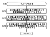
図7は、図1の電力制御装置4によって実行される電力制御処理を示すフローチャートである。ステップS1において、電力制御装置4の予測回路21は、各需要家設備1の現在の需要電力、発電電力、及び固有蓄電量に基づいて、単位時間期間における各需要家設備1の需要電力、発電電力、及び固有蓄電量を予測する。ステップS2において、電力制御装置4の過不足電力量計算回路22は、予測された需要電力、発電電力、及び固有蓄電量に基づいて、単位時間期間における各需要家設備1の余剰電力量及び不足電力量を計算する。ステップS3において、電力制御装置4のグループ化回路23は、グループ化処理を実行する。
FIG. 7 is a flowchart showing a power control process executed by the power control device 4 of FIG. In step S1, the
図8は、図7のステップS3のグループ化処理を示すサブルーチンである。ステップS11において、グループ化回路23は、単位時間期間における余剰電力量及び不足電力量の有無に応じて需要家設備1をクラスタリング(分類)する。需要家設備1は、以下のカテゴリーA~Dに分類される。
FIG. 8 is a subroutine showing the grouping process of step S3 of FIG. In step S11, the
A:単位時間期間において、固有蓄電量が上限蓄電量に達して余剰電力量を有するが、下限蓄電量には達しない(不足電力量なし)需要家設備1
B:単位時間期間において、固有蓄電量が下限蓄電量に達して不足電力量を有するが、上限蓄電量には達しない(余剰電力量なし)需要家設備1
C:単位時間期間において、固有蓄電量が上限蓄電量及び下限蓄電量の両方に達し、余剰電力量及び不足電力量の両方を有する需要家設備1
D:単位時間期間において、固有蓄電量が上限蓄電量及び下限蓄電量のどちらに達することもなく、余剰電力量及び不足電力量の両方をもたない需要家設備1A: In a unit time period, the intrinsic storage amount reaches the upper limit storage amount and has a surplus power amount, but does not reach the lower limit storage amount (no insufficient power amount).
B: In a unit time period, the intrinsic storage amount reaches the lower limit storage amount and has a shortage of power, but does not reach the upper limit storage amount (no surplus power amount).
C:
D:
本明細書では、カテゴリーA~Dの需要家設備1を「第1~第4の需要家設備」ともいう。
In the present specification, the
ステップS12において、グループ化回路23は、余剰電力量及び不足電力量の大きさに応じて需要家設備1をクラスタリングする。
In step S12, the
ステップS13において、グループ化回路23は、余剰電力量及び不足電力量を実質的に相殺するように2つ以上の需要家設備を組み合わせることによりグループを形成する。グループ化回路23は、少なくとも1つのカテゴリーAの需要家設備1と、少なくとも1つのカテゴリーBの需要家設備1とを組み合わせることにより、カテゴリーA及びBの需要家設備1を含む少なくとも1つのグループを形成してもよい。この場合、グループ化回路23は、単位時間期間において互いに最も近接した余剰電力量の合計値及び不足電力量の合計値をそれぞれ有する少なくとも1つのカテゴリーAの需要家設備1及び少なくとも1つのカテゴリーBの需要家設備1を組み合わせてもよい。また、グループ化回路23は、少なくとも1つのカテゴリーAの需要家設備1と、少なくとも1つのカテゴリーBの需要家設備1と、少なくとも1つのカテゴリーCの需要家設備1とを組み合わせることにより、カテゴリーA~Cの需要家設備1を含む少なくとも1つのグループを形成してもよい。この場合、グループ化回路23は、単位時間期間において互いに最も近接した余剰電力量の合計値及び不足電力量の合計値をそれぞれ有する少なくとも1つのカテゴリーAの需要家設備1及び少なくとも1つのカテゴリーCの需要家設備1を組み合わせ、単位時間期間において互いに最も近接した不足電力量の合計値及び余剰電力量の合計値をそれぞれ有する少なくとも1つのカテゴリーBの需要家設備1及び少なくとも1つのカテゴリーCの需要家設備1を組み合わせてもよい。
In step S13, the
図9は、図8のグループ化処理を実行することによって形成された例示的なグループを示す表である。図9の例では、電力システムは、カテゴリーAの需要家設備1(A-1、A-2、A-3)、カテゴリーBの需要家設備1(B-1、B-2、B-3)、カテゴリーCの需要家設備1(C-1)、及びカテゴリーDの需要家設備1(D-1)を含むものとする。余剰電力量及び不足電力量を実質的に相殺するように、需要家設備A-1、B-1を組み合わせ、需要家設備A-2、B-2を組み合わせ、需要家設備C-1、A-3、B-3を組み合わせることにより、それぞれグループを形成する。カテゴリーDの需要家設備D-1は、余剰電力量及び不足電力量を有しないので、他の需要家設備1とグループ化する必要はない。
FIG. 9 is a table showing exemplary groups formed by performing the grouping process of FIG. In the example of FIG. 9, the electric power system is the category A consumer equipment 1 (A-1, A-2, A-3) and the category B consumer equipment 1 (B-1, B-2, B-3). ), Category C consumer equipment 1 (C-1), and category D consumer equipment 1 (D-1). Consumer equipment A-1 and B-1 are combined, consumer equipment A-2 and B-2 are combined, and consumer equipment C-1 and A are combined so as to substantially offset the amount of surplus power and the amount of insufficient power. By combining -3 and B-3, each group is formed. The category D consumer equipment D-1 does not have a surplus electric energy amount and a shortage electric energy amount, and therefore does not need to be grouped with another
需要家設備A-1、B-1のグループにおいて、余剰電力量及び不足電力量は完全に一致していなくてもよい。例えば、需要家設備A-1の不足電力量が需要家設備B-1の余剰電力量よりもわずかに大きい場合、不足電力量を満たすように需要家設備B-1が需要家設備A-1へ余剰電力量よりも余分に送電しても、需要家設備B-1の蓄電装置13の蓄電量は下限蓄電量よりも十分に大きいと考えられる。同様に、需要家設備B-1の余剰電力量が需要家設備A-1の不足電力量よりもわずかに大きい場合、余剰電力量をすべて消費するように需要家設備B-1が需要家設備A-1へ不足電力量よりも余分に送電しても、需要家設備A-1の蓄電装置13の蓄電量は上限蓄電量よりも十分に小さいと考えられる。他のグループにおいても同様に、余剰電力量及び不足電力量は完全に一致していなくてもよい。
In the group of consumer equipment A-1 and B-1, the amount of surplus power and the amount of insufficient power do not have to be completely the same. For example, when the insufficient electric energy of the consumer equipment A-1 is slightly larger than the surplus electric energy of the consumer equipment B-1, the consumer equipment B-1 is the consumer equipment A-1 so as to satisfy the insufficient electric energy. Even if power is transmitted in excess of the excess electric energy, it is considered that the electric energy of the electric
図9に示すように、1つのグループにおいて、あるカテゴリーの需要家設備1を1つずつ含むのではなく、同じカテゴリーの複数の需要家設備1を含むように、需要家設備1を組み合わせてもよい。例えば、カテゴリーCの2つの需要家設備1と、カテゴリーAの1つの需要家設備1と、カテゴリーBの2つの需要家設備1とを組み合わせることにより、1つのグループを形成してもよい。
As shown in FIG. 9, even if the
需要家設備1のグループを形成するとき、余剰電力量及び不足電力量の有無及び大きさに加えて、余剰電力量及び不足電力量が発生する時刻又は時間帯、需要家設備1の間の距離、などを考慮してもよい。互いに離れた時間帯において余剰電力量及び不足電力量を有する需要家設備1の間で送受電する場合よりも、より近い時間帯において余剰電力量及び不足電力量を有する需要家設備1の間で送受電する場合のほうが、余剰電力量及び不足電力量の解消に成功する可能性が高い。余剰電力量が発生する時間と不足電力量が発生する時間とが離れていると、後述のステップS7で説明するように、需要電力及び発電電力などの条件が変化することにより、余剰電力量及び不足電力量の解消に失敗する可能性がある。また、送受電する需要家設備1の間の距離が近いほど、送受電による損失が小さくなる。従って、以下のように、送受電による損失を低減するように需要家設備1のグループを形成してもよい。
When forming a group of
図10は、図7のステップS3のグループ化処理の変形例を示すサブルーチンである。ステップS21において、グループ化回路23は、図8のステップS11と同様に、余剰電力量及び不足電力量の有無に応じて需要家設備1をクラスタリングする。
FIG. 10 is a subroutine showing a modified example of the grouping process in step S3 of FIG. In step S21, the
ステップS22において、グループ化回路23は、余剰電力量及び不足電力量の大きさ、発生時刻、及び場所に応じて需要家設備1をクラスタリングする。
In step S22, the
ステップS23において、グループ化回路23は、余剰電力量及び不足電力量を実質的に相殺するように2つ以上の需要家設備を組み合わせることによりグループを形成する。
In step S23, the
グループ化回路23は、単位時間期間において所定のしきい値(本明細書では、「第3のしきい値」ともいう)よりも互いに近接する余剰電力量の合計値及び不足電力量の合計値をそれぞれ有する少なくとも1つのカテゴリーAの需要家設備1及び少なくとも1つのカテゴリーBの需要家設備1の複数の組み合わせが利用可能であるとき、以下のように、カテゴリーA及びBの需要家設備1を含む少なくとも1つのグループを形成してもよい。グループ化回路23は、利用可能な各組み合わせのカテゴリーA及びBの需要家設備1のうち、単位時間期間のうちの互いに最も近接した部分時間期間において余剰電力量及び不足電力量をそれぞれ有する少なくとも1つのカテゴリーAの需要家設備1及び少なくとも1つのカテゴリーBの需要家設備1を組み合わせてもよい。また、グループ化回路23は、利用可能な各組み合わせのカテゴリーA及びBの需要家設備1のうち、互いに最も近接した場所に設けられた少なくとも1つのカテゴリーAの需要家設備1及び少なくとも1つのカテゴリーBの需要家設備1を組み合わせてもよい。
The
グループ化回路23は、単位時間期間において第3のしきい値よりも互いに近接する余剰電力量の合計値及び不足電力量の合計値をそれぞれ有する少なくとも1つのカテゴリーAの需要家設備1及び少なくとも1つのカテゴリーCの需要家設備1の複数の組み合わせが利用可能であり、かつ、単位時間期間において第3のしきい値よりも互いに近接する不足電力量の合計値及び余剰電力量の合計値をそれぞれ有する少なくとも1つのカテゴリーBの需要家設備1及び少なくとも1つのカテゴリーCの需要家設備1の複数の組み合わせが利用可能であるとき、以下のように、カテゴリーA~Cの需要家設備1を含む少なくとも1つのグループを形成してもよい。グループ化回路23は、利用可能な各組み合わせのカテゴリーA及びCの需要家設備1のうち、単位時間期間のうちの互いに最も近接した部分時間期間において余剰電力量及び不足電力量をそれぞれ有する少なくとも1つのカテゴリーAの需要家設備1及び少なくとも1つのカテゴリーCの需要家設備1を組み合わせてもよい。また、グループ化回路23は、利用可能な各組み合わせのカテゴリーB及びCの需要家設備1のうち、単位時間期間のうちの互いに最も近接した部分時間期間において不足電力量及び余剰電力量をそれぞれ有する少なくとも1つのカテゴリーBの需要家設備1及び少なくとも1つのカテゴリーCの需要家設備1を組み合わせてもよい。また、グループ化回路23は、利用可能な各組み合わせのカテゴリーA及びCの需要家設備1のうち、互いに最も近接した場所に設けられた少なくとも1つのカテゴリーAの需要家設備1及び少なくとも1つのカテゴリーCの需要家設備1を組み合わせてもよい。また、グループ化回路23は、利用可能な各組み合わせのカテゴリーB及びCの需要家設備1のうち、互いに最も近接した場所に設けられた少なくとも1つのカテゴリーBの需要家設備1及び少なくとも1つのカテゴリーCの需要家設備1を組み合わせてもよい。
The
グループ化回路23は、需要家設備1のグループを形成するとき、余剰電力量及び不足電力量の発生時刻と、需要家設備1の場所との両方を考慮してもよい。
When forming the group of the
図11は、図10のグループ化処理を実行することによって形成された例示的なグループを示す表である。図11の例では、電力システムは、カテゴリーAの需要家設備1(A-1、A-2、A-3)、カテゴリーBの需要家設備1(B-1、B-2、B-3)を含むものとする。同じ時刻又は互いに近接した時刻に発生した余剰電力量及び不足電力量を実質的に相殺するように、同じ場所又は互いに近接した場所に設けられた需要家設備A-1、B-1を組み合わせ、同じ場所又は互いに近接した場所に設けられた需要家設備A-2、B-2を組み合わせ、同じ場所又は互いに近接した場所に設けられた需要家設備A-3、B-3を組み合わせることにより、それぞれグループを形成する。 FIG. 11 is a table showing exemplary groups formed by performing the grouping process of FIG. In the example of FIG. 11, the electric power system is the category A consumer equipment 1 (A-1, A-2, A-3) and the category B consumer equipment 1 (B-1, B-2, B-3). ) Shall be included. Combining consumer equipment A-1 and B-1 installed in the same place or in close proximity to each other so as to substantially offset the amount of surplus power and the amount of insufficient power generated at the same time or close to each other. By combining consumer equipment A-2 and B-2 installed in the same place or in close proximity to each other, and by combining consumer equipment A-3 and B-3 installed in the same place or in close proximity to each other. Form a group for each.
需要家設備1のグループを形成するとき、さらに、過去のグループ化の結果、需要家設備1の間の送受電の成功率、などを考慮してもよい。
When forming a group of
再び図7を参照すると、ステップS4において、電力制御装置4の送受電制御回路24は、各需要家設備1の予測された需要電力、発電電力、及び固有蓄電量と、各需要家設備1の計算された余剰電力量及び不足電力量と、需要家設備1のグループとに基づいて、各グループにおいて、需要家設備1の需要電力の合計値、発電電力の合計値、及び蓄電量の合計値を計算する。
Referring to FIG. 7 again, in step S4, the power transmission /
ステップS5において、送受電制御回路24は、各グループにおいて、各需要家設備1の送電電力及び受電電力を決定する。ここで、送受電制御回路24は、各需要家設備1において、余剰電力量及び不足電力量が発生しないように、蓄電量が上限蓄電量及び下限蓄電量に達することがないように、かつ、蓄電量の変動を最小化するように、送電電力及び受電電力を決定する。送受電制御回路24は、カテゴリーA及びBの需要家設備1を含む各グループにおいて、需要家設備1の蓄電装置13の蓄電量が単位時間期間にわたって上限蓄電量以下かつ下限蓄電量以上になるように、カテゴリーAの需要家設備1からカテゴリーBの需要家設備1への送電電力を決定する。送受電制御回路24は、カテゴリーA~Cの需要家設備1を含む各グループにおいて、各需要家設備1の蓄電装置13の蓄電量が単位時間期間にわたって上限蓄電量以下かつ下限蓄電量以上になるように、カテゴリーAの需要家設備1からカテゴリーCの需要家設備1への送電電力と、カテゴリーCの需要家設備1からカテゴリーBの需要家設備1への送電電力とを決定する。送受電制御回路24は、カテゴリーDの需要家設備1には、他の需要家設備1との間で電力を送受信させない。
In step S5, the power transmission /
ステップS6において、送受電制御回路24は、各需要家設備1に送電及び受電を指示する。
In step S6, the power transmission /
ステップS7において、電力制御装置4の再構成判定回路25は、複数の需要家設備1の間の送受電を再構成するトリガを検出したか否かを判断し、YESのときはステップS1に戻り、NOのときはステップS7を繰り返す。
In step S7, the
ステップS3で決定された各グループの需要家設備1の間で、ステップS5で決定された電力を送受電しているとき、需要電力及び発電電力などの条件が変化すると、固有蓄電量、余剰電力量、及び不足電力量なども変化する。これにより、新たな余剰電力量又は新たな不足電力量が発生し、固定されたグループ、送電電力、及び受電電力のままでは、送受電できなくなる可能性がある。従って、再構成判定回路25は、以下のトリガを検出したとき、需要家設備1の間の送受電を再構成する。
When the power determined in step S5 is being transmitted / received between the
例えば、第1のトリガとして、単位時間期間ごとに、送受電を再構成してもよい。これにより、曜日ごとの需要電力の変化、平日又は休日による需要電力の変化に追従することができる。 For example, as the first trigger, the power transmission / reception may be reconfigured every unit time period. This makes it possible to follow changes in power demand for each day of the week and changes in power demand due to weekdays or holidays.
例えば、第2のトリガとして、予測回路21によって新たに予測された需要電力、発電電力、及び固有蓄電量のうちの少なくとも1つが、予測回路21によって以前に予測された需要電力、発電電力、及び固有蓄電量とは異なるとき、送受電を再構成してもよい。
For example, as a second trigger, at least one of the power demand, power generation, and intrinsic storage newly predicted by the
例えば、第3のトリガとして、実際の需要電力及び発電電力の少なくとも一方が、予測回路21によって以前に予測された需要電力及び発電電力とは異なるとき、送受電を再構成してもよい。これにより、予想外の天変地異、事故などに起因する送受電の中断に対処することができる。
For example, as a third trigger, power transmission / reception may be reconfigured when at least one of the actual demand power and the generated power is different from the demand power and the generated power previously predicted by the
例えば、第4のトリガとして、需要家設備1又は電力網2の故障又は停電などを検出したとき、送受電を再構成してもよい。これにより、需要家設備1(負荷装置11、発電装置12、蓄電装置13)及び電力網2の故障などに起因する送受電の中断に対処することができる。
For example, as the fourth trigger, when a failure or power failure of the
例えば、第5のトリガとして、未知の原因により、電力制御装置4から需要家設備1に指示した送受電が行われなかったとき、送受電を再構成してもよい。送受電を妨げる原因が不明であり、以後も送受電を実施可能になるか不明である場合にも対処することができる。
For example, as a fifth trigger, the power transmission / reception may be reconfigured when the power transmission / reception instructed by the power control device 4 to the
第3~第5のトリガは送受電が中断されたとき事後的に検出されるのに対して、第1及び第2のトリガは事前に検出可能である。実際の需要電力及び発電電力が予測された需要電力及び発電電力から許容誤差を超えて相違すると、ある程度の期間にわたって送受電を実施できなくなる可能性あるが、第1又は第2のトリガを用いて、そのような送受電の中断を回避することができる。 The third to fifth triggers are detected ex post facto when power transmission / reception is interrupted, whereas the first and second triggers can be detected in advance. If the actual power demand and power generation differ from the predicted power demand and power generation beyond the margin of error, it may not be possible to transmit and receive power for a certain period of time, but using the first or second trigger. , Such interruption of power transmission / reception can be avoided.
再構成判定回路25は、複数の需要家設備1の間の送受電を再構成するトリガを検出したとき、前述のように、再構成判定回路25から予測回路21、過不足電力量計算回路22、グループ化回路23、及び送受電制御回路24に再構成を指示する。
When the
図12A~図13Bを参照して、複数の需要家設備1の間の送受電を再構成することが必要になる場合の例について説明する。
An example of a case where it is necessary to reconfigure the power transmission / reception between the plurality of
図12Aは、ある需要家設備1についてユーザの帰宅時間に基づいて予測された、需要電力、発電電力、固有蓄電量、及びグループ内で送受電したときの予定蓄電量の時間変化を示す図である。図12Bは、図12Aと同じ需要家設備1の実際の需要電力、発電電力、及び蓄電量の時間変化を示す図である。図12Aによれば、ユーザが帰宅して需要電力が増大する前に、固有蓄電量が上限蓄電量に達し、余剰電力量が発生すると予測されている。電力制御装置4は、他の需要家設備1に送電するように指示する。しかしながら、図12Bによれば、ユーザの帰宅が早くなったことにより余剰電力量が発生しなくなったので、他の需要家設備1への送電も不要になる。このため、電力制御装置4は、ユーザの帰宅を検知したとき、他の需要家設備1に送電しないように送受電を再構成する。
FIG. 12A is a diagram showing the time change of the required power, the generated power, the inherent storage amount, and the planned storage amount when power is transmitted / received within the group, which is predicted based on the user's return time for a
図13Aは、ある需要家設備1について天気に基づいて予測された、需要電力、発電電力、固有蓄電量、及びグループ内で送受電したときの予定蓄電量の時間変化を示す図である。図13Bは、図13Aと同じ需要家設備1の実際の需要電力、発電電力、及び蓄電量の時間変化を示す図である。図13Aによれば、気象情報に基づいて、太陽電池である発電装置12の発電電力が予測されている。一方、図13Bによれば、雨雲の発生により発電電力が低下している。このため、電力制御装置4は、天候の変化を検出したとき、送受電を再構成する。
FIG. 13A is a diagram showing the time change of the demand power, the generated power, the intrinsic storage amount, and the planned storage amount when the power is transmitted / received within the group, which is predicted based on the weather for a
実施形態1に係る電力システムによれば、小容量の蓄電装置13を使用しながら、無駄なく安定的に負荷装置11に電力を供給するように、かつ、蓄電装置13の劣化を生じにくいように、複数の需要家設備1の間の送受電を低い計算負荷で制御することができる。
According to the electric power system according to the first embodiment, while using the small-capacity
実施形態1に係る電力システムによれば、蓄電装置13をそれぞれ備える複数の需要家設備1の少なくとも1つのグループを形成し、各グループの需要家設備1の間で送受電する。従って、小容量の蓄電装置13を使用しながら、無駄なく安定的に、各需要家設備1の負荷装置11に電力を供給することができる。
According to the electric power system according to the first embodiment, at least one group of a plurality of
実施形態1に係る電力システムによれば、各需要家設備1において、蓄電装置13の上限蓄電量に達したときの余剰電力量を他の需要家設備1に送電し、蓄電装置13の下限蓄電量に達したときの不足電力量を他の需要家設備1から受電する。従って、各需要家設備1の蓄電装置13の蓄電量を上限蓄電量以下かつ下限蓄電量以上にすることができるので、蓄電装置13の劣化を生じにくくすることができる。また、送受電する電力量も最小化されるので、送受電による損失を低減することができる。
According to the electric power system according to the first embodiment, in each
実施形態1に係る電力システムによれば、単位時間期間における需要電力、発電電力、及び固有蓄電量を予測し、単位時間期間において余剰電力量を有する需要家設備1と、単位時間期間において不足電力量を有する需要家設備1とを組み合わせてグループを形成する。これにより、単位時間期間のうちの未来の需要電力、発電電力、及び固有蓄電量を考慮して、各需要家設備1の送電電力及び受電電力を決定することができる。従って、例えば、単位時間期間のうちの未来に大きな需要電力量が発生すると予測される需要家設備1では、他の需要家設備1への送電を抑制し、蓄電量を維持することができる。仮に、蓄電量の現在の瞬時値のみに基づいて他の需要家設備1に送電するか否かを決定する場合には、未来に大きな需要電力量が発生するにもかかわらず他の需要家設備1に送電して蓄電量を低下させてしまい、その後、実際に大きな需要電力量が発生したときに蓄電量が不足し、他の需要家設備1から受電しなければならなくなる。実施形態1に係る電力システムによれば、単位時間期間の全体の需要電力、発電電力、及び固有蓄電量を考慮することにより、需要家設備1の間の無駄な送受電を防止することができる。
According to the electric power system according to the first embodiment, the
実施形態1に係る電力システムによれば、需要家設備1のグループを形成するとき、余剰電力量及び不足電力量の有無及び大きさに応じて需要家設備1をクラスタリングすることにより、計算負荷を低減することができる。例えば、クラスタリングを行わない場合、需要家設備1のすべての組み合わせについて送受電を行うか否かを判断しなければならず、計算負荷が非常に高く、制御のリアルタイム性が保証されない。一方、図8~図11に示すようにクラスタリングを行う場合、単位時間期間において互いに近接した余剰電力量及び不足電力量を有する需要家設備1の組み合わせについてのみ送受電を行うか否かを判断すればよく、計算負荷を低減することができる。余剰電力量及び不足電力量を有しない需要家設備1については、送受電を行うか否かを判断する必要がなく、計算負荷をさらに低減することができる。
According to the electric power system according to the first embodiment, when forming a group of the
実施形態1に係る電力システムによれば、各グループにおいて、需要電力と供給電力とをバランス化させることができる。需要電力と供給電力とをバランス化させるように需要家設備1のグループを形成することにより、蓄電量の変動を最小化することができると考えられる。
According to the power system according to the first embodiment, the demand power and the supply power can be balanced in each group. By forming a group of
実施形態1に係る電力システムによれば、各需要家設備1の蓄電装置13の容量を最小化しながら、需要家設備1自体において、又は、同じグループに含まれる他の需要家設備1において、発電電力を無駄なく自己消費する(すなわち、売電量を減らす)ことができる。
According to the electric power system according to the first embodiment, power is generated in the
実施形態1に係る電力システムによれば、複数の需要家設備1の間の送受電を再構成する回数がなるべく少なくなるように(例えば、単位時間期間より短い時間で送受電を再構成する必要がないように)、需要家設備1のグループを形成してもよい。
According to the power system according to the first embodiment, it is necessary to reconfigure the power transmission / reception in a time shorter than the unit time period so that the number of times of reconstructing the power transmission / reception between the plurality of
実施形態2.
電力制御装置4は、商用電力を利用可能である通常時と、停電などにより商用電力を利用可能でない非常時とで、各需要家設備1の蓄電装置13の上限蓄電量及び下限蓄電量の少なくとも一方を変化させてもよい。これにより、非常時において、蓄電装置13により充放電される電力量を増大することができる。
The power control device 4 has at least the upper limit storage amount and the lower limit storage amount of the
実施形態2に係る電力システムは、実施形態1に係る電力システムと同様に構成される。 The electric power system according to the second embodiment is configured in the same manner as the electric power system according to the first embodiment.
図14は、実施形態2に係る電力システムの電力制御装置4によって実行される電力制御処理を示すフローチャートである。 FIG. 14 is a flowchart showing a power control process executed by the power control device 4 of the power system according to the second embodiment.
ステップS31において、電力制御装置4は、非常時の上限蓄電量及び下限蓄電量を計算する。非常時の上限蓄電量及び下限蓄電量は、短時間であれば、蓄電装置13に過大な負荷をかけることなく、あまり劣化を生じることがないように蓄電装置13を動作させることができる蓄電量の上限値及び下限値である。例えば、非常時の上限蓄電量は、通常時の上限蓄電量よりも高く設定されてもよく、非常時の下限蓄電量は、通常時の下限蓄電量よりも低く設定されてもよい。
In step S31, the power control device 4 calculates the upper limit storage amount and the lower limit storage amount in an emergency. The upper limit storage amount and the lower limit storage amount in an emergency are the storage amounts that can operate the
ステップS32において、電力制御装置4は、商用電力が利用可能であるか否かを判断し、YESのときはステップS35に進み、NOのときはステップS33に進む。 In step S32, the power control device 4 determines whether or not commercial power is available, and if YES, the process proceeds to step S35, and if NO, the process proceeds to step S33.
ステップS33において、電力制御装置4は、過不足電力量計算回路22において、余剰電力量及び不足電力量を計算するときに使用される商用電力の値をゼロに設定する。ステップS34において、電力制御装置4は、過不足電力量計算回路22において、非常時の上限蓄電量及び下限蓄電量を設定する。
In step S33, the power control device 4 sets the value of the commercial power used when calculating the surplus power amount and the shortage power amount to zero in the excess / deficiency power
ステップS35において、電力制御装置4は、過不足電力量計算回路22において、余剰電力量及び不足電力量を計算するときに使用される商用電力のピークカット目標電力を設定する。ステップS36において、電力制御装置4は、過不足電力量計算回路22において、通常時の上限蓄電量及び下限蓄電量を設定する。
In step S35, the power control device 4 sets the peak cut target power of the commercial power used when calculating the surplus power amount and the shortage power amount in the excess / deficiency power
ステップS37~ステップS42は、図7のステップS1~S6と同様である。ただし、商用電力が利用可能でないとき、ステップS39のグループ化処理において、カテゴリーA~Cの需要家設備1とともにカテゴリーDの需要家設備1も組み合わせるようにグループを形成してもよい。カテゴリーDの需要家設備1に対して送受電することにより、非常時においてカテゴリーDの需要家設備1の蓄電装置13を有効に活用することができる。
Steps S37 to S42 are the same as steps S1 to S6 in FIG. However, when commercial power is not available, a group may be formed so as to combine the
ステップS42の後で、図7のステップS7と同様に、複数の需要家設備1の間の送受電を再構成するトリガを検出したか否かを判断してもよい。
After step S42, as in step S7 of FIG. 7, it may be determined whether or not a trigger for reconstructing power transmission / reception between the plurality of
実施形態2に係る電力システムによれば、商用電力が利用可能であるか否かに応じて、上限蓄電量及び下限蓄電量の少なくとも一方を変化させることにより、非常時において各需要家設備1の蓄電装置13を有効に活用することができる。非常時の上限蓄電量及び下限蓄電量を用いることにより、非常時のための蓄電量のバッファを確保することができる。
According to the electric power system according to the second embodiment, by changing at least one of the upper limit storage amount and the lower limit storage amount depending on whether or not commercial power is available, each
実施形態3.
電力システムの各需要家設備は、図1に示すように負荷装置11、発電装置12、及び蓄電装置13のすべてを備えたものに限定されない。電力システムは、発電装置12を備えていない需要家設備を含んでいてもよく、蓄電装置13を備えていない需要家設備を含んでいてもよい。
As shown in FIG. 1, each consumer equipment of the electric power system is not limited to the one including all of the
図15は、実施形態3に係る電力システムに含まれる需要家設備1Aの構成を示すブロック図である。需要家設備1A需要家制御装置10A、負荷装置11、及び蓄電装置13を備える。需要家制御装置10Aは、発電装置の発電電力をモニタリングしないことを除いて、図1の需要家制御装置10と同様に構成される。
FIG. 15 is a block diagram showing a configuration of
図16は、実施形態3に係る電力システムに含まれる需要家設備1Bの構成を示すブロック図である。需要家設備1Bは、需要家制御装置10B、負荷装置11、及び発電装置12を備える。需要家制御装置10Bは、蓄電装置の蓄電量をモニタリングしないことを除いて、図1の需要家制御装置10と同様に構成される。
FIG. 16 is a block diagram showing a configuration of
図17は、実施形態3に係る電力システムに含まれる需要家設備1Cの構成を示すブロック図である。需要家設備1Cは、需要家制御装置10C及び負荷装置11を備える。需要家制御装置10Cは、発電装置12の発電電力及び蓄電装置の蓄電量をモニタリングしないことを除いて、図1の需要家制御装置10と同様に構成される。
FIG. 17 is a block diagram showing a configuration of
実施形態3に係る電力システムにおいて、すべての需要家設備(需要家設備1、1A~1C)は負荷装置11をそれぞれ備える。実施形態3に係る電力システムにおいて、需要家設備のうちの少なくとも1つ(需要家設備1、1B)は発電装置12をさらに備える。実施形態3に係る電力システムにおいて、需要家設備のうちの少なくとも2つ(需要家設備1、1A)は蓄電装置13をさらに備える。以下の説明では、実施形態3に係る電力システムは、図1の需要家設備1、図15の需要家設備1A、図16の需要家設備1B、及び図17の需要家設備1Cのすべてを備えているものとする。
In the electric power system according to the third embodiment, all the consumer equipment (
実施形態3に係る電力制御装置4は、実施形態1に係る電力制御装置4と同様に構成され、例えば図2に示すように、予測回路21、過不足電力量計算回路22、グループ化回路23、送受電制御回路24、及び再構成判定回路25を備える。
The power control device 4 according to the third embodiment is configured in the same manner as the power control device 4 according to the first embodiment, and as shown in FIG. 2, for example, a
予測回路21は、発電装置12を備える各需要家設備1、1Bについて、単位時間期間における各需要家設備1、1Bの発電装置12の発電電力を予測する。予測回路21は、蓄電装置13を備える各需要家設備1、1Aについて、単位時間期間における各需要家設備1、1Aの蓄電装置13の蓄電量であって、他の需要家設備1、1A~1Cに対して電力を送受信しないときの蓄電量を示す固有蓄電量を予測する。
The
過不足電力量計算回路22は、発電装置12及び蓄電装置13を備える各需要家設備1について、需要電力、発電電力、及び固有蓄電量に基づいて、単位時間期間において固有蓄電量が上限蓄電量に達しているときに発電装置12によって発電されて負荷装置11によって消費されない余剰電力量を計算する。過不足電力量計算回路22は、蓄電装置13を備える各需要家設備1、1Aについて、需要電力及び固有蓄電量に基づいて、又は、需要電力、発電電力、及び固有蓄電量に基づいて、単位時間期間において固有蓄電量が下限蓄電量に達しているときに他の需要家設備1、1A~1Cから供給を受ける必要がある不足電力量を計算する。過不足電力量計算回路22は、発電装置12を備え、かつ、蓄電装置13を備えていない各需要家設備1Bについて、需要電力及び発電電力に基づいて、単位時間期間において発電装置12によって発電されて負荷装置11によって消費されない余剰電力量を計算し、単位時間期間において他の需要家設備1、1A~1Cから供給を受ける必要がある不足電力量を計算する。過不足電力量計算回路22は、発電装置12及び蓄電装置13を備えていない各需要家設備1Cについて、需要電力に基づいて、単位時間期間において他の需要家設備1、1A~1Cから供給を受ける必要がある不足電力量を計算する。
In the excess / deficiency electric
図1の需要家設備1及び図16の需要家設備1Bでは、余剰電力量及び不足電力量の両方が発生する可能性がある。一方、図15の需要家設備1A及び図17の需要家設備1Cでは、不足電力量が発生する可能性はあるが、発電装置を備えていないので余剰電力量が発生することはない。
In the
グループ化回路23は、複数の需要家設備1、1A~1Cのうち、蓄電装置13を備える少なくとも1つの需要家設備1、1Aを含むように、単位時間期間において余剰電力量を有する少なくとも1つの第1の需要家設備1、1Bと、単位時間期間において不足電力量を有する少なくとも1つの第2の需要家設備1、1A~1Cとを組み合わせることにより、第1及び第2の需要家設備1、1A~1Cを含む少なくとも1つのグループを形成する。電力制御装置4は、複数の需要家設備1、1A~1Cのうち、蓄電装置13を備える少なくとも1つの需要家設備1、1Aを含むように、単位時間期間において余剰電力量を有する少なくとも1つの第1の需要家設備1、1Bと、単位時間期間において不足電力量を有する少なくとも1つの第2の需要家設備1、1A~1Cと、単位時間期間において余剰電力量及び不足電力量の両方を有する少なくとも1つの第3の需要家設備1、1Bとを組み合わせることにより、第1~第3の需要家設備1、1A~1Cを含む少なくとも1つのグループを形成する。
The
送受電制御回路24は、第1及び第2の需要家設備1、1A~1Cを含む各グループにおいて、蓄電装置13を備える各需要家設備1の蓄電装置13の蓄電量が単位時間期間にわたって上限蓄電量以下かつ下限蓄電量以上になるように、第1の需要家設備1、1Bから第2の需要家設備1、1A~1Cへの送電電力を決定する。送受電制御回路24は、第1~第3の需要家設備1、1A~1Cを含む各グループにおいて、蓄電装置13を備える各需要家設備1、1Aの蓄電装置13の蓄電量が単位時間期間にわたって上限蓄電量以下かつ下限蓄電量以上になるように、第1の需要家設備1、1Bから第3の需要家設備1、1Bへの送電電力と、第3の需要家設備1、1Bから第2の需要家設備1、1A~1Cへの送電電力とを決定する。
In the power transmission /
需要家設備1、1A~1Cのグループは、例えば以下のように形成される。
The groups of
グループ化回路23は、複数の需要家設備1、1A~1Cのうち、単位時間期間において互いに最も近接した余剰電力量の合計値及び不足電力量の合計値をそれぞれ有する少なくとも1つの第1の需要家設備1、1B及び少なくとも1つの第2の需要家設備1、1A~1Cを組み合わせることにより、第1及び第2の需要家設備1、1A~1Cを含む少なくとも1つのグループを形成してもよい。また、グループ化回路23は、複数の需要家設備1、1A~1Cのうち、単位時間期間において互いに最も近接した余剰電力量の合計値及び不足電力量の合計値をそれぞれ有する少なくとも1つの第1の需要家設備1、1B及び少なくとも1つの第3の需要家設備1、1Bを組み合わせ、単位時間期間において互いに最も近接した不足電力量の合計値及び余剰電力量の合計値をそれぞれ有する少なくとも1つの第2の需要家設備1、1A~1C及び少なくとも1つの第3の需要家設備1、1Bを組み合わせることにより、第1~第3の需要家設備1、1A~1Cを含む少なくとも1つのグループを形成してもよい。
The
グループ化回路23は、単位時間期間において第3のしきい値よりも互いに近接する余剰電力量の合計値及び不足電力量の合計値をそれぞれ有する少なくとも1つの第1の需要家設備1、1B及び少なくとも1つの第2の需要家設備1、1A~1Cの複数の組み合わせが利用可能であるとき、以下のように、第1及び第2の需要家設備1、1A~1Cを含む少なくとも1つのグループを形成してもよい。グループ化回路23は、利用可能な各組み合わせの第1及び第2の需要家設備1、1A~1Cのうち、単位時間期間のうちの互いに最も近接した部分時間期間において余剰電力量及び不足電力量をそれぞれ有する少なくとも1つの第1の需要家設備1、1B及び少なくとも1つの第2の需要家設備1、1A~1Cを組み合わせてもよい。グループ化回路23は、利用可能な各組み合わせの第1及び第2の需要家設備1、1A~1Cのうち、互いに最も近接した場所に設けられた少なくとも1つの第1の需要家設備1、1B及び少なくとも1つの第2の需要家設備1、1A~1Cを組み合わせてもよい。
The
グループ化回路23は、単位時間期間において第3のしきい値よりも互いに近接する余剰電力量の合計値及び不足電力量の合計値をそれぞれ有する少なくとも1つの第1の需要家設備1、1B及び少なくとも1つの第3の需要家設備1、1Bの複数の組み合わせが利用可能であり、かつ、単位時間期間において第3のしきい値よりも互いに近接する不足電力量の合計値及び余剰電力量の合計値をそれぞれ有する少なくとも1つの第2の需要家設備1、1A~1C及び少なくとも1つの第3の需要家設備1、1Bの複数の組み合わせが利用可能であるとき、以下のように、第1~第3の需要家設備1、1A~1Cを含む少なくとも1つのグループを形成してもよい。グループ化回路23は、利用可能な各組み合わせの第1及び第3の需要家設備1、1Bのうち、単位時間期間のうちの互いに最も近接した部分時間期間において余剰電力量及び不足電力量をそれぞれ有する少なくとも1つの第1の需要家設備1、1B及び少なくとも1つの第3の需要家設備1、1Bを組み合わせてもよい。グループ化回路23は、利用可能な各組み合わせの第2及び第3の需要家設備1、1A~1Cのうち、単位時間期間のうちの互いに最も近接した部分時間期間において不足電力量及び余剰電力量をそれぞれ有する少なくとも1つの第2の需要家設備1、1A~1C及び少なくとも1つの第3の需要家設備1、1Bを組み合わせてもよい。グループ化回路23は、利用可能な各組み合わせの第1及び第3の需要家設備1、1Bのうち、互いに最も近接した場所に設けられた少なくとも1つの第1の需要家設備1、1B及び少なくとも1つの第3の需要家設備1、1Bを組み合わせてもよい。グループ化回路23は、利用可能な各組み合わせの第2及び第3の需要家設備1、1A~1Cのうち、互いに最も近接した場所に設けられた少なくとも1つの第2の需要家設備1、1A~1C及び少なくとも1つの第3の需要家設備1、1Bを組み合わせてもよい。
The
グループ化回路23は、需要家設備1、1A~1Cのグループを形成するとき、余剰電力量及び不足電力量の発生時刻と、需要家設備1、1A~1Cの場所との両方を考慮してもよい。
When forming a group of
実施形態3に係る電力システムにおいて、需要家設備1Cのみを含むグループは形成されない。これは、図17の需要家設備1Cは余剰電力量を有しないからである。一方、実施形態3に係る電力システムにおいて、図15の需要家設備1Aのみを含むグループは形成されてもよく、図15の需要家設備1A及び図17の需要家設備1Cを含むグループは形成されてもよい。これらのグループでは、商用電力(夜間電力など)により蓄電装置に充電されてもよいが、停電などに起因して商用電力が利用可能でない場合には、これらのグループは形成されない。
In the electric power system according to the third embodiment, a group including only the
実施形態3に係る電力システムによれば、発電装置及び蓄電装置の少なくとも一方を備えていない需要家設備が存在しても、小容量の蓄電装置13を使用しながら、無駄なく安定的に負荷装置11に電力を供給するように、かつ、蓄電装置13の劣化を生じにくいように、複数の需要家設備1の間の送受電を低い計算負荷で制御することができる。
According to the electric power system according to the third embodiment, even if there is a consumer facility that does not have at least one of a power generation device and a power storage device, the load device is stably loaded without waste while using the small capacity
実施形態4.
図18は、実施形態4に係る電力システムの構成を示すブロック図である。図18の電力システムは、複数の電力グリッド設備101-1~101-4、電力網2、電力会社設備3、及び電力制御装置4Aを含む。Embodiment 4.
FIG. 18 is a block diagram showing a configuration of the electric power system according to the fourth embodiment. The power system of FIG. 18 includes a plurality of power grid facilities 101-1 to 101-4, a
電力グリッド設備101-1は、複数の需要家設備1-1~1-4及び電力グリッド制御装置5をそれぞれ含む。電力グリッド設備101-1の需要家設備1-1~1-4は、図1の需要家設備1、図15の需要家設備1A、図16の需要家設備1B、又は図17の需要家設備1Cと同様に構成される。電力グリッド制御装置5は、電力グリッド設備101-1に含まれる各需要家設備1の負荷装置11の需要電力、発電装置12の発電電力、及び蓄電装置13の蓄電量をモニタリングし、その結果を電力制御装置4Aに通知する。
The power grid equipment 101-1 includes a plurality of consumer equipment 1-1 to 1-4 and a power
他の電力グリッド設備101-2~101-4もまた、電力グリッド設備101-1と同様に構成される。本明細書では、電力グリッド設備101-1~101-4を総称して「電力グリッド設備101」とも表記する。 The other power grid facilities 101-2 to 101-4 are also configured in the same manner as the power grid facilities 101-1. In this specification, the electric power grid equipment 101-1 to 101-4 are collectively referred to as "electric power grid equipment 101".
電力制御装置4Aは、図2の電力制御装置4と実質的に同様に構成され、予測回路、過不足電力量計算回路、グループ化回路、送受電制御回路、及び再構成判定回路を備える。
The
電力制御装置4Aの予測回路は、単位時間期間における各電力グリッド設備101の負荷装置11の需要電力を予測する。電力制御装置4Aの予測回路は、発電装置12を備える各電力グリッド設備101について、単位時間期間における各電力グリッド設備101の発電装置12の発電電力を予測する。電力制御装置4Aの予測回路は、蓄電装置13を備える各電力グリッド設備101について、単位時間期間における各電力グリッド設備101の蓄電装置13の蓄電量であって、他の電力グリッド設備101に対して電力を送受信しないときの蓄電量を示す固有蓄電量を予測する。
The prediction circuit of the
電力制御装置4Aの過不足電力量計算回路は、発電装置12及び蓄電装置13を備える各電力グリッド設備101について、需要電力、発電電力、及び固有蓄電量に基づいて、単位時間期間において固有蓄電量が第1のしきい値に達しているときに発電装置12によって発電されて負荷装置11によって消費されない余剰電力量を計算する。電力制御装置4Aの過不足電力量計算回路は、蓄電装置13を備える各電力グリッド設備101について、需要電力及び固有蓄電量に基づいて、又は、需要電力、発電電力、及び固有蓄電量に基づいて、単位時間期間において固有蓄電量が第1のしきい値より小さい第2のしきい値に達しているときに他の電力グリッド設備101から供給を受ける必要がある不足電力量を計算する。
The excess / deficiency electric energy calculation circuit of the electric
電力制御装置4Aのグループ化回路は、蓄電装置13を備える各電力グリッド設備101のうち、単位時間期間において余剰電力量を有する少なくとも1つの第1の電力グリッド設備101と、単位時間期間において不足電力量を有する少なくとも1つの第2の電力グリッド設備101とを組み合わせることにより、第1及び第2の電力グリッド設備101を含む少なくとも1つのグループを形成する。
The grouping circuit of the
電力制御装置4Aの送受電制御回路は、第1及び第2の電力グリッド設備101を含む各グループにおいて、第1及び第2の電力グリッド設備101の蓄電装置13の蓄電量が単位時間期間にわたって第1のしきい値以下かつ第2のしきい値以上になるように、第1の電力グリッド設備101から第2の電力グリッド設備101への送電電力を決定する。
In the power transmission / reception control circuit of the
図19は、図18の電力制御装置4Aによって実行される電力制御処理を示すフローチャートである。
FIG. 19 is a flowchart showing a power control process executed by the
ステップS51において、電力制御装置4Aの予測回路は、各電力グリッド設備101の現在の需要電力、発電電力、及び固有蓄電量に基づいて、単位時間期間における各電力グリッド設備101の需要電力、発電電力、及び固有蓄電量を予測する。
In step S51, the prediction circuit of the
ステップS52において、電力制御装置4Aの過不足電力量計算回路は、予測された需要電力、発電電力、及び固有蓄電量に基づいて、単位時間期間における各電力グリッド設備101の余剰電力量及び不足電力量を計算する。
In step S52, the excess / deficiency electric energy calculation circuit of the
ステップS53において、電力制御装置4Aのグループ化回路は、グループ化処理を実行する。
In step S53, the grouping circuit of the
ステップS54において、電力制御装置4Aの送受電制御回路は、各電力グリッド設備101の予測された需要電力、発電電力、及び固有蓄電量と、各電力グリッド設備101の計算された余剰電力量及び不足電力量と、電力グリッド設備101のグループとに基づいて、各グループにおいて、電力グリッド設備101の需要電力の合計値、発電電力の合計値、及び蓄電量の合計値を計算する。
In step S54, the power transmission / reception control circuit of the
ステップS55において、電力制御装置4Aの送受電制御回路は、各グループにおいて、各電力グリッド設備101の送電電力及び受電電力を決定する。
In step S55, the power transmission / reception control circuit of the
ステップS56において、電力制御装置4Aの送受電制御回路は、各電力グリッド設備101に送電及び受電を指示する。
In step S56, the power transmission / reception control circuit of the
ステップS57において、電力制御装置4Aの再構成判定回路は、複数の電力グリッド設備101の間の送受電を再構成するトリガを検出したか否かを判断し、YESのときはステップS51に戻り、NOのときはステップS57を繰り返す。
In step S57, the reconstruction determination circuit of the
実施形態4に係る電力システムによれば、小容量の蓄電装置13を使用しながら、無駄なく安定的に負荷装置11に電力を供給するように、かつ、蓄電装置13の劣化を生じにくいように、複数の需要家設備1の間の送受電を低い計算負荷で制御することができる。実施形態4によれば、実施形態1に係る電力システムよりも大規模な電力システムに適用可能であることがわかる。
According to the electric power system according to the fourth embodiment, while using the small-capacity
各実施形態に係る電力システムは、商用電力に接続されていない電力網及び需要家設備にも適用可能である。 The electric power system according to each embodiment can also be applied to an electric power grid and consumer equipment that are not connected to commercial electric power.
本開示に係る電力システムは、ある需要家設備で発生した発電電力をその需要家設備又は近隣の需要家設備で消費する「地産地消型電力システム」として実現可能である。小容量の蓄電装置を用いることにより蓄電装置の初期投資費用を低減し、蓄電量の変動を最小化して、あまり劣化を生じることがないように長期間にわたって蓄電装置13を動作させることができる。
The electric power system according to the present disclosure can be realized as a "local production / local consumption type electric power system" in which the generated power generated by a certain consumer equipment is consumed by the consumer equipment or a neighboring consumer equipment. By using the small-capacity power storage device, the initial investment cost of the power storage device can be reduced, the fluctuation of the storage amount can be minimized, and the
1-1~1-4,1A,1B,1C…需要家設備、
2…電力網、
3…電力会社設備、
4,4A…電力制御装置、
5…電力グリッド制御装置、
10,10A,10B,10C…需要家制御装置、
11…負荷装置、
12…発電装置、
13…蓄電装置、
21…予測回路、
22…過不足電力量計算回路、
23…グループ化回路、
24…送受電制御回路、
25…再構成判定回路、
101-1~101-4…電力グリッド設備。1-1 to 1-4, 1A, 1B, 1C ... Consumer equipment,
2 ... power grid,
3 ... Electric power company equipment,
4,4A ... Power control device,
5 ... Power grid controller,
10, 10A, 10B, 10C ... Consumer control device,
11 ... Load device,
12 ... Power generation equipment,
13 ... Power storage device,
21 ... Prediction circuit,
22 ... Excess / deficiency electric energy calculation circuit,
23 ... Grouping circuit,
24 ... Power transmission / reception control circuit,
25 ... Reconstruction judgment circuit,
101-1 to 101-4 ... Power grid equipment.
Claims (21)
前記複数の需要家設備は負荷装置をそれぞれ備え、前記複数の需要家設備のうちの少なくとも1つは発電装置をさらに備え、前記複数の需要家設備のうちの少なくとも2つは蓄電装置をさらに備え、
前記電力制御装置は、予測器と、過不足電力量計算器と、グループ形成器と、送受電制御器とを備え、
前記予測器は、
単位時間期間における前記各需要家設備の前記負荷装置の需要電力を予測し、
前記発電装置を備える各需要家設備について、前記単位時間期間における前記各需要家設備の前記発電装置の発電電力を予測し、
前記蓄電装置を備える各需要家設備について、前記単位時間期間における前記各需要家設備の前記蓄電装置の蓄電量であって、他の需要家設備に対して電力を送受信しないときの蓄電量を示す固有蓄電量を予測し、
前記過不足電力量計算器は、
前記発電装置及び前記蓄電装置を備える各需要家設備について、前記需要電力、前記発電電力、及び前記固有蓄電量に基づいて、前記単位時間期間において前記固有蓄電量が第1のしきい値に達しているときに前記発電装置によって発電されて前記負荷装置によって消費されない余剰電力量を計算し、
前記蓄電装置を備える各需要家設備について、前記需要電力及び前記固有蓄電量に基づいて、又は、前記需要電力、前記発電電力、及び前記固有蓄電量に基づいて、前記単位時間期間において前記固有蓄電量が前記第1のしきい値より小さい第2のしきい値に達しているときに他の需要家設備から供給を受ける必要がある不足電力量を計算し、
前記グループ形成器は、前記蓄電装置を備える各需要家設備のうち、前記単位時間期間において余剰電力量を有する少なくとも1つの第1の需要家設備と、前記単位時間期間において不足電力量を有する少なくとも1つの第2の需要家設備とを組み合わせることにより、前記第1及び第2の需要家設備を含む少なくとも1つのグループを形成し、
前記送受電制御器は、前記第1及び第2の需要家設備を含む各グループにおいて、前記第1及び第2の需要家設備の前記蓄電装置の蓄電量が前記単位時間期間にわたって前記第1のしきい値以下かつ前記第2のしきい値以上になるように、前記第1の需要家設備から前記第2の需要家設備への送電電力を決定する、
電力制御装置。A power control unit for a power system that includes multiple consumer equipment connected to each other via a power grid.
Each of the plurality of consumer equipment is provided with a load device, at least one of the plurality of consumer equipment is further equipped with a power generation device, and at least two of the plurality of consumer equipment are further equipped with a power storage device. ,
The power control device includes a predictor, an excess / deficiency power amount calculator, a group forming device, and a power transmission / reception controller.
The predictor is
Predict the power demand of the load device of each consumer equipment in a unit time period,
For each consumer equipment equipped with the power generation device, the power generated by the power generation device of the consumer equipment in the unit time period is predicted.
For each consumer equipment equipped with the power storage device, the amount of electricity stored in the power storage device of each consumer equipment in the unit time period, and indicates the amount of power stored when power is not transmitted to or received from other consumer equipment. Predict the amount of stored electricity
The excess / deficiency electric energy calculator
For each consumer equipment provided with the power generation device and the power storage device, the specific power storage amount reaches the first threshold value in the unit time period based on the demand power, the power generation power, and the specific power storage amount. The amount of surplus power generated by the power generation device and not consumed by the load device is calculated.
For each consumer equipment provided with the power storage device, the specific power storage is performed in the unit time period based on the demand power and the specific power storage amount, or based on the demand power, the power generation power, and the specific power storage amount. Calculate the amount of underpower that needs to be supplied by other consumer equipment when the quantity reaches a second threshold smaller than the first threshold.
The group former includes at least one first consumer equipment having a surplus electric energy in the unit time period and at least one having a shortage electric energy in the unit time period among the consumer equipment provided with the power storage device. By combining with one second consumer equipment, at least one group including the first and second consumer equipment is formed.
In each group including the first and second consumer equipment, the power transmission / reception controller has the first storage amount of the power storage device of the first and second consumer equipment over the unit time period. The power transmitted from the first consumer equipment to the second consumer equipment is determined so as to be equal to or less than the threshold value and greater than or equal to the second threshold value.
Power control device.
前記過不足電力量計算器は、前記発電装置及び前記蓄電装置を備えていない各需要家設備について、前記需要電力に基づいて、前記単位時間期間において他の需要家設備から供給を受ける必要がある不足電力量を計算し、
前記グループ形成器は、前記複数の需要家設備のうち、前記蓄電装置を備える少なくとも1つの需要家設備を含むように、前記単位時間期間において余剰電力量を有する少なくとも1つの第1の需要家設備と、前記単位時間期間において不足電力量を有する少なくとも1つの第2の需要家設備とを組み合わせることにより、前記第1及び第2の需要家設備を含む少なくとも1つのグループを形成し、
前記送受電制御器は、前記第1及び第2の需要家設備を含む各グループにおいて、前記蓄電装置を備える各需要家設備の前記蓄電装置の蓄電量が前記単位時間期間にわたって前記第1のしきい値以下かつ前記第2のしきい値以上になるように、前記第1の需要家設備から前記第2の需要家設備への送電電力を決定する、
請求項1記載の電力制御装置。The excess / deficiency electric energy calculator is provided by the power generation device in the unit time period based on the demand power and the generated power for each consumer equipment provided with the power generation device and not equipped with the power storage device. The amount of surplus power generated and not consumed by the load device is calculated, and the amount of insufficient power that needs to be supplied from other consumer equipment during the unit time period is calculated.
The excess / deficiency electric energy calculator needs to receive supply from other consumer equipment in the unit time period based on the demand power for each consumer equipment not equipped with the power generation device and the power storage device. Calculate the amount of power shortage,
The group former is at least one first consumer equipment having a surplus power amount in the unit time period so as to include at least one consumer equipment provided with the power storage device among the plurality of consumer equipment. And at least one second consumer equipment having a shortage of power in the unit time period to form at least one group including the first and second consumer equipment.
In each group including the first and second consumer equipment, the power transmission / reception controller has the first power storage amount of the power storage device of each consumer equipment provided with the power storage device over the unit time period. The power transmitted from the first consumer equipment to the second consumer equipment is determined so as to be equal to or less than the threshold value and equal to or more than the second threshold value.
The power control device according to claim 1.
請求項1又は2記載の電力制御装置。The group former is at least one first consumer equipment having a total value of surplus electric energy and a total value of insufficient electric energy closest to each other in the unit time period among the plurality of consumer equipment. By combining at least one second consumer equipment, at least one group including the first and second consumer equipment is formed.
The power control device according to claim 1 or 2.
請求項1又は2記載の電力制御装置。The group former is at least one first consumer equipment and at least one having a total value of surplus power and a total value of insufficient power that are closer to each other than the third threshold in the unit time period. When a plurality of combinations of two second consumer equipments are available, the closest partial time of the unit time period of the first and second consumer equipments of each of the available combinations. By combining at least one first consumer equipment and at least one second consumer equipment each having a surplus power amount and a shortage power amount in a period, at least one including the first and second consumer equipment. Forming two groups,
The power control device according to claim 1 or 2.
請求項1又は2記載の電力制御装置。The group former is at least one first consumer equipment and at least one having a total value of surplus electric energy and a total value of insufficient electric energy that are closer to each other than the third threshold value in the unit time period. When a plurality of combinations of two second consumer equipments are available, at least one of the first and second consumer equipments of each of the available combinations provided at the closest location to each other. By combining one consumer equipment and at least one second consumer equipment, at least one group including the first and second consumer equipment is formed.
The power control device according to claim 1 or 2.
前記送受電制御器は、前記第1~第3の需要家設備を含む各グループにおいて、前記蓄電装置を備える各需要家設備の前記蓄電装置の蓄電量が前記単位時間期間にわたって前記第1のしきい値以下かつ前記第2のしきい値以上になるように、前記第1の需要家設備から前記第3の需要家設備への送電電力と、前記第3の需要家設備から前記第2の需要家設備への送電電力とを決定する、
請求項1又は2記載の電力制御装置。The group former is at least one first consumer equipment having a surplus power amount in the unit time period so as to include at least one consumer equipment equipped with the power storage device among the plurality of consumer equipment. And at least one second consumer equipment having a shortage of power in the unit time period, and at least one third consumer equipment having both a surplus power amount and a shortage power amount in the unit time period. By combining, at least one group including the first to third consumer equipment is formed.
In each group including the first to third consumer equipment, the power transmission / reception controller has the first power storage amount of the power storage device of each consumer equipment provided with the power storage device over the unit time period. The power transmitted from the first consumer equipment to the third consumer equipment and the second from the third consumer equipment so as to be equal to or less than the threshold value and equal to or more than the second threshold value. Determine the power to be transmitted to the consumer equipment,
The power control device according to claim 1 or 2.
請求項6記載の電力制御装置。The group former is at least one first consumer equipment having a total value of surplus power and a total value of insufficient power that are closest to each other in the unit time period among the plurality of consumer equipment. At least one second consumer equipment and at least one that combines at least one third consumer equipment and has the total value of the shortage power and the total value of the surplus power that are closest to each other in the unit time period, respectively. By combining the third consumer equipment, at least one group including the first to third consumer equipment is formed.
The power control device according to claim 6.
前記単位時間期間において第3のしきい値よりも互いに近接する余剰電力量の合計値及び不足電力量の合計値をそれぞれ有する少なくとも1つの第1の需要家設備及び少なくとも1つの第3の需要家設備の複数の組み合わせが利用可能であるとき、前記利用可能な各組み合わせの第1及び第3の需要家設備のうち、前記単位時間期間のうちの互いに最も近接した部分時間期間において余剰電力量及び不足電力量をそれぞれ有する少なくとも1つの第1の需要家設備及び少なくとも1つの第3の需要家設備を組み合わせ、
前記単位時間期間において前記第3のしきい値よりも互いに近接する不足電力量の合計値及び余剰電力量の合計値をそれぞれ有する少なくとも1つの第2の需要家設備及び少なくとも1つの第3の需要家設備の複数の組み合わせが利用可能であるとき、前記利用可能な各組み合わせの第2及び第3の需要家設備のうち、前記単位時間期間のうちの互いに最も近接した部分時間期間において不足電力量及び余剰電力量をそれぞれ有する少なくとも1つの第2の需要家設備及び少なくとも1つの第3の需要家設備を組み合わせ、
これにより、前記第1~第3の需要家設備を含む少なくとも1つのグループを形成する、
請求項6記載の電力制御装置。The group former
At least one first consumer equipment and at least one third consumer having a total value of surplus power and a total value of insufficient power that are closer to each other than the third threshold in the unit time period. When a plurality of combinations of equipment are available, the amount of surplus power and the amount of surplus power in the closest partial time period of the unit time period of the first and third consumer equipment of each of the available combinations. Combining at least one first consumer equipment and at least one third consumer equipment, each with a shortage of power,
At least one second consumer equipment and at least one third demand having a total value of insufficient power amount and a total value of surplus power amount closer to each other than the third threshold value in the unit time period. When multiple combinations of home equipment are available, the amount of power shortage in the second and third consumer equipment of each of the available combinations in the closest partial time period of the unit time period. And at least one second consumer equipment and at least one third consumer equipment, each with a surplus power amount,
As a result, at least one group including the first to third consumer equipment is formed.
The power control device according to claim 6.
前記単位時間期間において第3のしきい値よりも互いに近接する余剰電力量の合計値及び不足電力量の合計値をそれぞれ有する少なくとも1つの第1の需要家設備及び少なくとも1つの第3の需要家設備の複数の組み合わせが利用可能であるとき、前記利用可能な各組み合わせの第1及び第3の需要家設備のうち、互いに最も近接した場所に設けられた少なくとも1つの第1の需要家設備及び少なくとも1つの第3の需要家設備を組み合わせ、
前記単位時間期間において前記第3のしきい値よりも互いに近接する不足電力量の合計値及び余剰電力量の合計値をそれぞれ有する少なくとも1つの第2の需要家設備及び少なくとも1つの第3の需要家設備の複数の組み合わせが利用可能であるとき、前記利用可能な各組み合わせの第2及び第3の需要家設備のうち、互いに最も近接した場所に設けられた少なくとも1つの第2の需要家設備及び少なくとも1つの第3の需要家設備を組み合わせ、
これにより、前記第1~第3の需要家設備を含む少なくとも1つのグループを形成する、
請求項6記載の電力制御装置。The group former
At least one first consumer equipment and at least one third consumer having a total value of surplus electric energy and a total value of insufficient electric energy that are closer to each other than the third threshold value in the unit time period. When a plurality of combinations of equipment are available, at least one first consumer equipment and at least one of the first and third consumer equipment of each of the available combinations provided at the closest location to each other. Combining at least one third consumer equipment,
At least one second consumer equipment and at least one third demand having a total value of insufficient power and a total value of surplus power that are closer to each other than the third threshold value in the unit time period. When a plurality of combinations of house equipment are available, at least one second consumer equipment provided at the closest location to each other among the second and third consumer equipment of each of the available combinations. And at least one third consumer facility,
As a result, at least one group including the first to third consumer equipment is formed.
The power control device according to claim 6.
請求項1~9のうちの1つに記載の電力制御装置。In the power transmission / reception controller, among the plurality of consumer equipment, the fourth consumer equipment having no surplus electric energy and insufficient electric energy in the unit time period is connected to other consumer equipment. Do not send or receive
The power control device according to any one of claims 1 to 9.
請求項1~10のうちの1つに記載の電力制御装置。The power control device responds to a predetermined trigger, predicts the demand power, the generated power, and the intrinsic power storage amount, calculates the surplus power amount, and the shortage power amount, and the at least one group. Is further provided with a reconstruction determination device that repeats the formation of the above and the determination of the transmitted power.
The power control device according to any one of claims 1 to 10.
請求項11記載の電力制御装置。The reconstruction determination device predicts the demand power, the generated power, and the intrinsic power storage amount, calculates the surplus power amount, and the shortage power amount, and the at least one group, for each unit time period. Repeating the formation and the determination of the transmitted power,
The power control device according to claim 11.
請求項11又は12記載の電力制御装置。In the reconstruction determination device, at least one of the newly predicted demand power, the generated power, and the intrinsic storage amount is the previously predicted demand power, the generated power, and the intrinsic storage amount. When different from, the calculation of the surplus power amount and the shortage power amount, the formation of the at least one group, and the determination of the transmission power are repeated.
The power control device according to claim 11 or 12.
請求項11~13のうちの1つに記載の電力制御装置。When at least one of the actual demand power and the generated power is different from the predicted demand power and the generated power, the reconstruction determiner determines the demand power, the generated power, and the intrinsic electric energy. The prediction, the calculation of the surplus power amount and the shortage power amount, the formation of the at least one group, and the determination of the transmission power are repeated.
The power control device according to any one of claims 11 to 13.
請求項11~14のうちの1つに記載の電力制御装置。When the reconstruction determination device detects a failure of the consumer equipment or the power network, it predicts the demand power, the generated power, and the intrinsic power storage amount, and calculates the surplus power amount and the shortage power amount. , The formation of the at least one group and the determination of the transmitted power are repeated.
The power control device according to any one of claims 11 to 14.
請求項1~15のうちの1つに記載の電力制御装置。Each of the consumer equipment is connected to the power company equipment and is supplied with commercial power from the power company equipment.
The power control device according to any one of claims 1 to 15.
前記商用電力のピークカット目標電力の設定値を有し、
前記ピークカット目標電力にさらに基づいて、前記余剰電力量及び前記不足電力量を計算する、
請求項16記載の電力制御装置。The excess / deficiency electric energy calculator
It has a set value of the peak cut target power of the commercial power,
The surplus power amount and the shortage power amount are calculated based on the peak cut target power.
The power control device according to claim 16.
請求項16又は17記載の電力制御装置。The excess / deficiency power calculator changes at least one of the first and second thresholds depending on whether the commercial power is available.
The power control device according to claim 16 or 17.
請求項1~18のうちの1つに記載の電力制御装置とを含む、
電力システム。With multiple consumer equipment connected to each other via the power grid,
The power control device according to any one of claims 1 to 18.
Power system.
請求項19記載の電力システム。Whether or not each of the consumer equipment satisfies a predetermined condition for transmitting power to the other consumer equipment when instructed by the power control device to transmit power to the other consumer equipment. Each of them is provided with a consumer control device that determines and transmits power to the other consumer equipment only when the above conditions are satisfied.
The power system according to claim 19.
前記電力システムは、前記複数の需要家設備のうちの少なくとも2つの需要家設備をそれぞれ含む複数の電力グリッド設備を含み、
前記複数の電力グリッド設備は負荷装置をそれぞれ備え、前記複数の電力グリッド設備のうちの少なくとも1つは発電装置をさらに備え、前記複数の電力グリッド設備のうちの少なくとも2つは蓄電装置をさらに備え、
前記電力制御装置は、予測器と、過不足電力量計算器と、グループ形成器と、送受電制御器とを備え、
前記予測器は、
単位時間期間における前記各電力グリッド設備の前記負荷装置の需要電力を予測し、
前記発電装置を備える各電力グリッド設備について、前記単位時間期間における前記各電力グリッド設備の前記発電装置の発電電力を予測し、
前記蓄電装置を備える各電力グリッド設備について、前記単位時間期間における前記各電力グリッド設備の前記蓄電装置の蓄電量であって、他の電力グリッド設備に対して電力を送受信しないときの蓄電量を示す固有蓄電量を予測し、
前記過不足電力量計算器は、
前記発電装置及び前記蓄電装置を備える各電力グリッド設備について、前記需要電力、前記発電電力、及び前記固有蓄電量に基づいて、前記単位時間期間において前記固有蓄電量が第1のしきい値に達しているときに前記発電装置によって発電されて前記負荷装置によって消費されない余剰電力量を計算し、
前記蓄電装置を備える各電力グリッド設備について、前記需要電力及び前記固有蓄電量に基づいて、又は、前記需要電力、前記発電電力、及び前記固有蓄電量に基づいて、前記単位時間期間において前記固有蓄電量が前記第1のしきい値より小さい第2のしきい値に達しているときに他の電力グリッド設備から供給を受ける必要がある不足電力量を計算し、
前記グループ形成器は、前記蓄電装置を備える各電力グリッド設備のうち、前記単位時間期間において余剰電力量を有する少なくとも1つの第1の電力グリッド設備と、前記単位時間期間において不足電力量を有する少なくとも1つの第2の電力グリッド設備とを組み合わせることにより、前記第1及び第2の電力グリッド設備を含む少なくとも1つのグループを形成し、
前記送受電制御器は、前記第1及び第2の電力グリッド設備を含む各グループにおいて、前記第1及び第2の電力グリッド設備の前記蓄電装置の蓄電量が前記単位時間期間にわたって前記第1のしきい値以下かつ前記第2のしきい値以上になるように、前記第1の電力グリッド設備から前記第2の電力グリッド設備への送電電力を決定する、
電力制御装置。A power control unit for a power system that includes multiple consumer equipment connected to each other via a power grid.
The power system includes a plurality of power grid facilities including at least two consumer facilities of the plurality of consumer facilities.
The plurality of power grid facilities are each provided with a load device, at least one of the plurality of power grid facilities is further equipped with a power generation device, and at least two of the plurality of power grid facilities are further equipped with a power storage device. ,
The power control device includes a predictor, an excess / deficiency power amount calculator, a group forming device, and a power transmission / reception controller.
The predictor is
Predict the power demand of the load device of each power grid facility in a unit time period,
For each power grid facility equipped with the power generation device, the power generated by the power generation device of each power grid facility in the unit time period is predicted.
For each power grid facility provided with the power storage device, the amount of power stored in the power storage device of each power grid facility in the unit time period, and indicates the amount of power stored when power is not transmitted to or received from other power grid equipment. Predict the amount of stored electricity
The excess / deficiency electric energy calculator
For each power grid facility including the power generation device and the power storage device, the specific power storage amount reaches the first threshold value in the unit time period based on the demand power, the power generation power, and the specific power storage amount. The amount of surplus power generated by the power generation device and not consumed by the load device is calculated.
For each power grid facility provided with the power storage device, the specific power storage is performed in the unit time period based on the demand power and the specific power storage amount, or based on the demand power, the generated power generation, and the specific power storage amount. Calculate the amount of underpower that needs to be supplied by another power grid facility when the amount reaches a second threshold smaller than the first threshold.
The group former includes at least one first power grid facility having a surplus power amount in the unit time period and at least one insufficient power amount in the unit time period among the power grid facilities provided with the power storage device. By combining with one second power grid facility, at least one group including the first and second power grid facilities is formed.
In each group including the first and second power grid equipment, the power transmission / reception controller has the first power storage amount of the power storage device of the first and second power grid equipment over the unit time period. The power transmitted from the first power grid equipment to the second power grid equipment is determined so as to be equal to or less than the threshold value and equal to or higher than the second threshold value.
Power control device.
Applications Claiming Priority (3)
| Application Number | Priority Date | Filing Date | Title |
|---|---|---|---|
| JP2017047714 | 2017-03-13 | ||
| JP2017047714 | 2017-03-13 | ||
| PCT/JP2018/008998 WO2018168646A1 (en) | 2017-03-13 | 2018-03-08 | Power control device and power system |
Publications (2)
| Publication Number | Publication Date |
|---|---|
| JPWO2018168646A1 JPWO2018168646A1 (en) | 2020-01-09 |
| JP7002041B2 true JP7002041B2 (en) | 2022-01-20 |
Family
ID=63523417
Family Applications (1)
| Application Number | Title | Priority Date | Filing Date |
|---|---|---|---|
| JP2019505940A Active JP7002041B2 (en) | 2017-03-13 | 2018-03-08 | Power controller and power system |
Country Status (4)
| Country | Link |
|---|---|
| US (1) | US10833505B2 (en) |
| JP (1) | JP7002041B2 (en) |
| CN (1) | CN110419151B (en) |
| WO (1) | WO2018168646A1 (en) |
Families Citing this family (9)
| Publication number | Priority date | Publication date | Assignee | Title |
|---|---|---|---|---|
| TWI705013B (en) * | 2017-12-29 | 2020-09-21 | 英屬開曼群島商睿能創意公司 | Exchangeable energy storage device station and method for managing exchangeable energy storage device station |
| JP2019146330A (en) * | 2018-02-19 | 2019-08-29 | 本田技研工業株式会社 | Power supply system and power supply device |
| US11817710B2 (en) * | 2018-08-07 | 2023-11-14 | Kyocera Corporation | Control apparatus and control method for controlling charge and discharge of storage battery apparatuses |
| US10326305B1 (en) * | 2018-08-27 | 2019-06-18 | Ekergy Llc | Personal power plant system and methods of inverse energy generation |
| JP7110963B2 (en) * | 2018-12-11 | 2022-08-02 | トヨタ自動車株式会社 | Wind power generation system using a hovering kite-shaped structure |
| JP2020188559A (en) * | 2019-05-13 | 2020-11-19 | 株式会社デンソー | Region controller, building controller, and energy management system |
| US20220043414A1 (en) * | 2020-08-05 | 2022-02-10 | Korea Advanced Institute Of Science And Technology | Apparatus and method for operating energy storage system |
| WO2023074149A1 (en) * | 2021-10-26 | 2023-05-04 | 株式会社Nttドコモ | Power control system |
| KR102537638B1 (en) * | 2022-11-18 | 2023-05-31 | 주식회사 크로커스 | Voltage control device based on the measured equipment load voltage |
Citations (3)
| Publication number | Priority date | Publication date | Assignee | Title |
|---|---|---|---|---|
| JP2004015882A (en) | 2002-06-05 | 2004-01-15 | Mitsubishi Heavy Ind Ltd | Distributed power supply system and method and operation program |
| JP2013187935A (en) | 2012-03-06 | 2013-09-19 | Yahoo Japan Corp | System, information processing method, and computer program |
| JP2016010276A (en) | 2014-06-26 | 2016-01-18 | 三菱電機株式会社 | Energy management system |
Family Cites Families (11)
| Publication number | Priority date | Publication date | Assignee | Title |
|---|---|---|---|---|
| CN101682195A (en) * | 2007-03-26 | 2010-03-24 | Vpec株式会社 | Power system |
| JP5467010B2 (en) | 2010-07-22 | 2014-04-09 | ニチコン株式会社 | Learning-type storage battery management system |
| JP2012252580A (en) * | 2011-06-03 | 2012-12-20 | Sony Corp | Power control device, power management device and power management system |
| JP5364768B2 (en) | 2011-09-26 | 2013-12-11 | 株式会社東芝 | Electricity supply and demand scheduling device |
| WO2014033800A1 (en) | 2012-08-27 | 2014-03-06 | 株式会社日立製作所 | Consumer collaboration support device |
| WO2014068815A1 (en) | 2012-10-31 | 2014-05-08 | 株式会社 東芝 | Power management device and power management system |
| JP2014222396A (en) * | 2013-05-13 | 2014-11-27 | パナソニック株式会社 | Management device, equipment management method, and management system |
| CN105324790A (en) * | 2013-06-26 | 2016-02-10 | 三菱电机株式会社 | Demand-supply planning device, demand-supply planning method, demand-supply planning program, and recording medium |
| JP6148120B2 (en) * | 2013-08-29 | 2017-06-14 | 京セラ株式会社 | Energy management apparatus, energy management method, and energy management system |
| DE112014006204T5 (en) | 2014-02-13 | 2016-11-03 | Hitachi, Ltd. | Performance Exchange Management System and Performance Exchange Management Procedures |
| CN106104954A (en) * | 2014-03-12 | 2016-11-09 | 日本电气株式会社 | The record medium of battery sharing system, information processor, battery method for sharing and record battery shared routine |
-
2018
- 2018-03-08 US US16/493,596 patent/US10833505B2/en active Active
- 2018-03-08 CN CN201880018137.6A patent/CN110419151B/en active Active
- 2018-03-08 WO PCT/JP2018/008998 patent/WO2018168646A1/en active Application Filing
- 2018-03-08 JP JP2019505940A patent/JP7002041B2/en active Active
Patent Citations (3)
| Publication number | Priority date | Publication date | Assignee | Title |
|---|---|---|---|---|
| JP2004015882A (en) | 2002-06-05 | 2004-01-15 | Mitsubishi Heavy Ind Ltd | Distributed power supply system and method and operation program |
| JP2013187935A (en) | 2012-03-06 | 2013-09-19 | Yahoo Japan Corp | System, information processing method, and computer program |
| JP2016010276A (en) | 2014-06-26 | 2016-01-18 | 三菱電機株式会社 | Energy management system |
Also Published As
| Publication number | Publication date |
|---|---|
| JPWO2018168646A1 (en) | 2020-01-09 |
| US10833505B2 (en) | 2020-11-10 |
| US20200083711A1 (en) | 2020-03-12 |
| CN110419151B (en) | 2022-11-15 |
| WO2018168646A1 (en) | 2018-09-20 |
| CN110419151A (en) | 2019-11-05 |
Similar Documents
| Publication | Publication Date | Title |
|---|---|---|
| JP7002041B2 (en) | Power controller and power system | |
| Huang et al. | Review of congestion management methods for distribution networks with high penetration of distributed energy resources | |
| JP7460701B2 (en) | Power supply system and power supply method | |
| KR101945501B1 (en) | Control system and method for providing electric power using solar energy generation and energy storage system | |
| Burger et al. | Why distributed?: A critical review of the tradeoffs between centralized and decentralized resources | |
| US9893526B2 (en) | Networked power management and demand response | |
| US20130178998A1 (en) | Systems and methods for controlling power systems | |
| CA2609344A1 (en) | Fast acting distributed power system for transmission and distribution system load using energy storage units | |
| US9153963B2 (en) | Electric power control apparatus and grid connection system having same | |
| EP2721706B1 (en) | Method and apparatus for controlling energy services based on market data | |
| JP6592360B2 (en) | Power management method | |
| US10482548B2 (en) | Method and apparatus for performing energy management in a power supply grid | |
| Abniki et al. | Reliability improvement in smart grid through incorporating energy storage systems in service restoration | |
| US20120330671A1 (en) | System and method for implementing congestion pricing in a power distribution network | |
| WO2016144357A1 (en) | Power distribution plan | |
| KR101918625B1 (en) | System and method for providing power service to a plurality of customers using an energy storage device | |
| JP5752069B2 (en) | Power control system | |
| WO2019211826A1 (en) | System and method for managing a hierarchic power distribution grid | |
| KR101496187B1 (en) | Apparatus for virtual power plant service and method therefor | |
| US20140324737A1 (en) | Switching Input Power Sources for Mobile Telecom Sites According to Time-Varying Electricity Prices | |
| WO2020044743A1 (en) | Power control device and power system | |
| JP6936097B2 (en) | Power management device and power management method | |
| Ceseña et al. | Techno-economic assessment of distribution network reliability services from microgrids | |
| JP2020048370A (en) | Power management method and power management system | |
| JP7225142B2 (en) | Power source management system |
Legal Events
| Date | Code | Title | Description |
|---|---|---|---|
| A621 | Written request for application examination |
Free format text: JAPANESE INTERMEDIATE CODE: A621 Effective date: 20210210 |
|
| TRDD | Decision of grant or rejection written | ||
| A01 | Written decision to grant a patent or to grant a registration (utility model) |
Free format text: JAPANESE INTERMEDIATE CODE: A01 Effective date: 20211207 |
|
| A61 | First payment of annual fees (during grant procedure) |
Free format text: JAPANESE INTERMEDIATE CODE: A61 Effective date: 20211210 |
|
| R151 | Written notification of patent or utility model registration |
Ref document number: 7002041 Country of ref document: JP Free format text: JAPANESE INTERMEDIATE CODE: R151 |