JP7000090B2 - Packet aggregation device, packet division device, packet communication system, program, packet generation device, packet generation method and communication method - Google Patents

Packet aggregation device, packet division device, packet communication system, program, packet generation device, packet generation method and communication method Download PDF

Info

Publication number
JP7000090B2
JP7000090B2 JP2017181740A JP2017181740A JP7000090B2 JP 7000090 B2 JP7000090 B2 JP 7000090B2 JP 2017181740 A JP2017181740 A JP 2017181740A JP 2017181740 A JP2017181740 A JP 2017181740A JP 7000090 B2 JP7000090 B2 JP 7000090B2
Authority
JP
Japan
Prior art keywords
packet
aggregated
individual
packets
processor
Prior art date
Legal status (The legal status is an assumption and is not a legal conclusion. Google has not performed a legal analysis and makes no representation as to the accuracy of the status listed.)
Active
Application number
JP2017181740A
Other languages
Japanese (ja)
Other versions
JP2019057846A (en
Inventor
遵 金井
直哉 大西
拓紀 松山
Current Assignee (The listed assignees may be inaccurate. Google has not performed a legal analysis and makes no representation or warranty as to the accuracy of the list.)
Toshiba Corp
Toshiba Infrastructure Systems and Solutions Corp
Original Assignee
Toshiba Corp
Toshiba Infrastructure Systems and Solutions Corp
Priority date (The priority date is an assumption and is not a legal conclusion. Google has not performed a legal analysis and makes no representation as to the accuracy of the date listed.)
Filing date
Publication date
Application filed by Toshiba Corp, Toshiba Infrastructure Systems and Solutions Corp filed Critical Toshiba Corp
Priority to JP2017181740A priority Critical patent/JP7000090B2/en
Publication of JP2019057846A publication Critical patent/JP2019057846A/en
Application granted granted Critical
Publication of JP7000090B2 publication Critical patent/JP7000090B2/en
Active legal-status Critical Current
Anticipated expiration legal-status Critical

Links

Images

Landscapes

  • Data Exchanges In Wide-Area Networks (AREA)

Description

本発明の実施形態は、パケット集約装置、パケット分割装置、パケット通信システム、プログラム、パケット生成装置、パケット生成方法及び通信方法に関する。 An embodiment of the present invention relates to a packet aggregation device, a packet division device, a packet communication system, a program, a packet generation device, a packet generation method, and a communication method.

クライアントサーバーモデルのシステムなどにおいて、クライアントからサーバーに対して多数のアクサスが発生する場合がある。このような場合、ネットワーク又はサーバーなどに対する負荷が増大する。特に、小さいサイズのパケットを大量に処理する場合には、サーバーのネットワークインターフェースなどに対する処理負荷が増大する。 In a client-server model system, a large number of axes may occur from the client to the server. In such a case, the load on the network or the server increases. In particular, when processing a large number of small-sized packets, the processing load on the network interface of the server increases.

特開2003-169092号公報Japanese Unexamined Patent Application Publication No. 2003-169902

本発明の実施形態が解決しようとする課題は、処理負荷を低減し、リアルタイム性の低下を抑える、パケット集約装置、パケット分割装置、パケット通信システム、プログラム、パケット生成装置、パケット生成方法及び通信方法を提供することである。 The problem to be solved by the embodiment of the present invention is a packet aggregation device, a packet division device, a packet communication system, a program, a packet generation device, a packet generation method, and a communication method, which reduce the processing load and suppress the deterioration of real-time performance. Is to provide.

実施形態のパケット処理装置は、受信部、処理部及び送信部を含む。受信部は、個別パケットを受信する。処理部は、前記受信部によって受信された複数の個別パケットを集約した集約パケットを生成し、生成した前記集約パケットのうちの暗号化済みでないと判定した範囲を暗号化する。送信部は、前記処理部によって暗号化された集約パケットを送信する。 The packet processing device of the embodiment includes a receiving unit, a processing unit, and a transmitting unit. The receiving unit receives individual packets. The processing unit generates an aggregated packet that aggregates a plurality of individual packets received by the receiving unit, and encrypts a range of the generated aggregated packets that is determined not to be encrypted. The transmitting unit transmits the aggregated packet encrypted by the processing unit.

第1実施形態及び第2実施形態に係る通信システム及び当該通信システムに含まれる装置の要部回路構成を示すブロック図。The block diagram which shows the main part circuit composition of the communication system which concerns on 1st Embodiment and 2nd Embodiment and the apparatus included in the said communication system. 図1中のパケット集約装置の第1実施形態に係る機能構成を示すブロック図。FIG. 3 is a block diagram showing a functional configuration according to the first embodiment of the packet aggregation device in FIG. 1. 図1中のパケット集約装置が備えるプロセッサーによる第1実施形態~第3実施形態に係る処理の一例を示すフローチャート。The flowchart which shows an example of the process which concerns on 1st Embodiment to 3rd Embodiment by the processor provided in the packet aggregation apparatus in FIG. 図1中のパケット集約装置が備えるプロセッサーによる第1実施形態及び第2実施形態に係る処理の一例を示すフローチャート。The flowchart which shows an example of the process which concerns on 1st Embodiment and 2nd Embodiment by the processor provided in the packet aggregation apparatus in FIG. 図1中のパケット集約装置が備えるプロセッサーによる第1実施形態及び第2実施形態に係る処理の一例を示すフローチャート。The flowchart which shows an example of the process which concerns on 1st Embodiment and 2nd Embodiment by the processor provided in the packet aggregation apparatus in FIG. 図1中のサーバー装置が備えるプロセッサーによる第1実施形態及び第2実施形態に係る処理の一例を示すフローチャート。The flowchart which shows an example of the process which concerns on 1st Embodiment and 2nd Embodiment by the processor provided in the server apparatus in FIG. 図1中のサーバー装置が備えるプロセッサーによる第1実施形態及び第2実施形態に係る処理の一例を示すフローチャート。The flowchart which shows an example of the process which concerns on 1st Embodiment and 2nd Embodiment by the processor provided in the server apparatus in FIG. 図1中のサーバー装置が備えるプロセッサーによる第1実施形態~第3実施形態に係る処理の一例を示すフローチャート。The flowchart which shows an example of the process which concerns on 1st Embodiment to 3rd Embodiment by the processor provided in the server apparatus in FIG. 第1実施形態に係る集約パケットの一例を説明するための図。The figure for demonstrating an example of the aggregated packet which concerns on 1st Embodiment. 第2実施形態に係る集約パケットの一例を説明するための図。The figure for demonstrating an example of the aggregated packet which concerns on 2nd Embodiment. 図1中のパケット集約装置の第3実施形態に係る機能構成を示すブロック図。FIG. 3 is a block diagram showing a functional configuration according to a third embodiment of the packet aggregation device in FIG. 1. 図1中のパケット集約装置が備えるプロセッサーによる第3実施形態に係る処理の一例を示すフローチャート。The flowchart which shows an example of the process which concerns on 3rd Embodiment by the processor provided in the packet aggregation apparatus in FIG. 図1中のパケット集約装置が備えるプロセッサーによる第3実施形態に係る処理の一例を示すフローチャート。The flowchart which shows an example of the process which concerns on 3rd Embodiment by the processor provided in the packet aggregation apparatus in FIG. 第3実施形態に係る集約パケットの一例を説明するための図。The figure for demonstrating an example of the aggregated packet which concerns on 3rd Embodiment. 第3実施形態に係る通信システムの情報の流れの一例を示すシーケンス図。The sequence diagram which shows an example of the information flow of the communication system which concerns on 3rd Embodiment.

以下、いくつかの実施形態に係る通信システムについて図面を用いて説明する。
〔第1実施形態〕
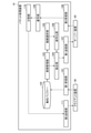
図1は、第1実施形態に係る通信システム1及び通信システム1に含まれる構成要素の要部回路構成の一例を示すブロック図である。通信システム1は、パケット処理装置10、サーバー装置20及びクライアント装置30を含む。通信システム1は、一例として、サーバー装置20とクライアント装置30との間で通信を行う、サーバークライアントモデルのシステムである。なお、図1にはパケット処理装置10を1台、サーバー装置20を1台、クライアント装置30を3台示しているが、これらの台数に限定するものではない。
Hereinafter, the communication system according to some embodiments will be described with reference to the drawings.
[First Embodiment]
FIG. 1 is a block diagram showing an example of a main circuit configuration of components included in the communication system 1 and the communication system 1 according to the first embodiment. Communication system 1 includes a packet processing device 10, a server device 20, and a client device 30. The communication system 1 is, for example, a server-client model system that communicates between the server device 20 and the client device 30. Note that FIG. 1 shows one packet processing device 10, one server device 20, and three client devices 30, but the number is not limited to these.

パケット処理装置10及びクライアント装置30は、ネットワークNW1に接続されている。ネットワークNW1は、典型的にはLAN(local area network)を含む通信網である。ネットワークNW1は、典型的にはイントラネットなどのプライベートネットワークを含む通信網である。ネットワークNW1は、インターネットを含む通信網であっても良い。ネットワークNW1は、WAN(wide area network)を含む通信網であっても良い。
パケット処理装置10及びサーバー装置20は、ネットワークNW2に接続されている。ネットワークNW2は、典型的には、インターネットを含む通信網である。ネットワークNWは1、典型的には、WANを含む通信網である。ネットワークNW2は、イントラネットなどのプライベートネットワークを含む通信網であっても良い。ネットワークNW2は、LANを含む通信網であっても良い。
ネットワークNW1及びネットワークNW2のそれぞれは、携帯電話回線網、専用線、又はその他の通信網を含む通信網であっても良い。
ネットワークNW1及びネットワークNW2上の通信は、パケット通信によって行われる。
The packet processing device 10 and the client device 30 are connected to the network NW1. The network NW1 is typically a communication network including a LAN (local area network). The network NW1 is typically a communication network including a private network such as an intranet. The network NW1 may be a communication network including the Internet. The network NW1 may be a communication network including a WAN (wide area network).
The packet processing device 10 and the server device 20 are connected to the network NW2. The network NW2 is typically a communication network that includes the Internet. The network NW is 1, typically a communication network including a WAN. The network NW2 may be a communication network including a private network such as an intranet. The network NW2 may be a communication network including a LAN.
Each of the network NW1 and the network NW2 may be a communication network including a mobile phone line network, a dedicated line, or another communication network.
Communication on network NW1 and network NW2 is performed by packet communication.

パケット処理装置10は、例えばゲートウェイ又はルーターなどである。パケット処理装置10は、サーバー装置20とクライアント装置30との間の通信を中継する。パケット処理装置10は、クライアント装置30などから送信された複数のパケットを1つのパケットに集約する機能を有する。なお、複数のパケットが集約されたパケットを、以下「集約パケット」という。また、集約パケットでないパケットを、以下「個別パケット」という。また、パケット処理装置10は、サーバー装置20などから送信された集約パケットを個々の個別パケットに分割する機能を有する。さらに、パケット処理装置10は、集約パケットを暗号化する機能、及び暗号化された集約パケットを復号する機能を有する。パケット処理装置10は、プロセッサー11、ROM(read-only memory)12、RAM(random-access memory)13、補助記憶デバイス14、第1の通信I/F(interface)15及び第2の通信I/F16を含む。パケット処理装置10は、パケット集約装置の一例である。パケット処理装置10は、パケット分割装置の一例である。パケット処理装置10は、パケット生成装置の一例である。 The packet processing device 10 is, for example, a gateway or a router. The packet processing device 10 relays communication between the server device 20 and the client device 30. The packet processing device 10 has a function of aggregating a plurality of packets transmitted from a client device 30 or the like into one packet. A packet in which a plurality of packets are aggregated is hereinafter referred to as an "aggregated packet". Further, a packet that is not an aggregate packet is hereinafter referred to as an "individual packet". Further, the packet processing device 10 has a function of dividing the aggregated packet transmitted from the server device 20 or the like into individual individual packets. Further, the packet processing device 10 has a function of encrypting the aggregated packet and a function of decrypting the encrypted aggregated packet. The packet processing device 10 includes a processor 11, a ROM (read-only memory) 12, a RAM (random-access memory) 13, an auxiliary storage device 14, a first communication I / F (interface) 15, and a second communication I /. Includes F16. The packet processing device 10 is an example of a packet aggregation device. The packet processing device 10 is an example of a packet dividing device. The packet processing device 10 is an example of a packet generation device.

プロセッサー11は、パケット処理装置10の動作に必要な演算及び制御などの処理を行うコンピューターの中枢部分に相当する。プロセッサー11は、ROM12又は補助記憶デバイス14などに記憶されたシステムソフトウェア、アプリケーションソフトウェア又はファームウェアなどのプログラムに基づいて、パケット処理装置10の各種の機能を実現するべく各部を制御する。プロセッサー11は、例えば、CPU(central processing unit)、MPU(micro processing unit)、SoC(system on a chip)、DSP(digital signal processor)、GPU(graphics processing unit)、ASIC(application specific integrated circuit)、PLD(programmable logic device)又はFPGA(field-programmable gate array)などである。あるいは、プロセッサー11は、これらの組み合わせである。プロセッサー11は、処理部の一例である。プロセッサー11は、第1の処理部の一例である。プロセッサー11は、第2の処理部の一例である。プロセッサー11は、生成部の一例である。プロセッサー11を中枢とするコンピューターは、処理部の値例である。プロセッサー11を中枢とするコンピューターは、第1の処理部の一例である。プロセッサー11を中枢とするコンピューターは、第2の処理部の一例である。プロセッサー11を中枢とするコンピューターは、生成部の一例である。 The processor 11 corresponds to a central part of a computer that performs processing such as calculation and control necessary for the operation of the packet processing device 10. The processor 11 controls each unit to realize various functions of the packet processing device 10 based on a program such as system software, application software, or firmware stored in the ROM 12 or the auxiliary storage device 14. The processor 11 is, for example, a CPU (central processing unit), an MPU (micro processing unit), a SOC (system on a chip), a DSP (digital signal processor), a GPU (graphics processing unit), an ASIC (application specific integrated circuit), and the like. PLD (programmable logic device) or FPGA (field-programmable gate array). Alternatively, the processor 11 is a combination of these. The processor 11 is an example of a processing unit. The processor 11 is an example of a first processing unit. The processor 11 is an example of a second processing unit. The processor 11 is an example of a generation unit. The computer centered on the processor 11 is a value example of the processing unit. A computer centered on the processor 11 is an example of a first processing unit. A computer centered on the processor 11 is an example of a second processing unit. A computer centered on the processor 11 is an example of a generator.

ROM12は、プロセッサー11を中枢とするコンピューターの主記憶装置に相当する。ROM12は、専らデータの読み出しに用いられる不揮発性メモリである。ROM12は、上記のプログラムを記憶する。また、ROM12は、プロセッサー11が各種の処理を行う上で使用するデータ又は各種の設定値などを記憶する。 The ROM 12 corresponds to the main storage device of a computer centered on the processor 11. The ROM 12 is a non-volatile memory used exclusively for reading data. The ROM 12 stores the above program. Further, the ROM 12 stores data or various set values used by the processor 11 for performing various processes.

RAM13は、プロセッサー11を中枢とするコンピューターの主記憶装置に相当する。RAM13は、データの読み書きに用いられるメモリである。RAM13は、プロセッサー11が各種の処理を行う上で一時的に使用するデータを記憶しておく、いわゆるワークエリアなどとして利用される。 The RAM 13 corresponds to the main storage device of a computer centered on the processor 11. The RAM 13 is a memory used for reading and writing data. The RAM 13 is used as a so-called work area or the like for storing data temporarily used by the processor 11 for performing various processes.

補助記憶デバイス14は、プロセッサー11を中枢とするコンピューターの補助記憶装置に相当する。補助記憶デバイス14は、例えばEEPROM(electric erasable programmable read-only memory)、HDD(hard disk drive)又はSSD(solid state drive)などである。補助記憶デバイス14は、上記のプログラムを記憶する場合がある。また、補助記憶デバイス14は、プロセッサー11が各種の処理を行う上で使用するデータ、プロセッサー11での処理によって生成されたデータ又は各種の設定値などを保存する。 The auxiliary storage device 14 corresponds to an auxiliary storage device of a computer centered on the processor 11. The auxiliary storage device 14 is, for example, an EEPROM (electric erasable programmable read-only memory), an HDD (hard disk drive), an SSD (solid state drive), or the like. The auxiliary storage device 14 may store the above program. Further, the auxiliary storage device 14 stores data used by the processor 11 for performing various processes, data generated by the processes of the processor 11, various setting values, and the like.

ROM12又は補助記憶デバイス14に記憶されるプログラムは、後述する処理を実行するためのプログラムを含む。一例として、パケット処理装置10は、当該プログラムがROM12又は補助記憶デバイス14に記憶された状態でパケット処理装置10の管理者などへと譲渡される。しかしながら、パケット処理装置10は、当該プログラムがROM12又は補助記憶デバイス14に記憶されない状態で当該管理者などに譲渡されても良い。また、パケット処理装置10は、当該プログラムとは別のプログラムがROM12又は補助記憶デバイス14に記憶された状態で当該管理者などに譲渡されても良い。そして、後述する処理を実行するためのプログラムが別途に当該管理者などへと譲渡され、当該管理者又はサービスマンなどによる操作の下にROM12又は補助記憶デバイス14へと書き込まれても良い。このときのプログラムの譲渡は、例えば、磁気ディスク、光磁気ディスク、光ディスク又は半導体メモリなどのようなリムーバブルな記憶媒体に記録して、あるいはネットワークを介したダウンロードにより実現できる。 The program stored in the ROM 12 or the auxiliary storage device 14 includes a program for executing a process described later. As an example, the packet processing device 10 is transferred to the administrator of the packet processing device 10 or the like in a state where the program is stored in the ROM 12 or the auxiliary storage device 14. However, the packet processing device 10 may be transferred to the administrator or the like in a state where the program is not stored in the ROM 12 or the auxiliary storage device 14. Further, the packet processing device 10 may be transferred to the administrator or the like in a state where a program different from the program is stored in the ROM 12 or the auxiliary storage device 14. Then, the program for executing the process described later may be separately transferred to the administrator or the like and written to the ROM 12 or the auxiliary storage device 14 under the operation of the administrator or the serviceman. The transfer of the program at this time can be realized by recording on a removable storage medium such as a magnetic disk, a magneto-optical disk, an optical disk, or a semiconductor memory, or by downloading via a network.

第1の通信I/F15は、パケット処理装置10がネットワークNW1などを介して通信するためのインターフェースである。第1の通信I/F15は、個別パケットを受信する受信部の一例である。第1の通信I/F15は、個別パケットを受信する第4の通信部の一例である。 The first communication I / F 15 is an interface for the packet processing device 10 to communicate via the network NW1 or the like. The first communication I / F 15 is an example of a receiving unit that receives individual packets. The first communication I / F 15 is an example of a fourth communication unit that receives individual packets.

第2の通信I/F16は、パケット処理装置10がネットワークNW2などを介して通信するためのインターフェースである。第2の通信I/F16は、集約パケットを送信する送信部の一例である。第2の通信I/F16は、集約パケットをパケット分割装置に送信する第1の通信部の一例である。第2の通信I/F16は、集約パケットを受信する第2の通信部の一例である。 The second communication I / F 16 is an interface for the packet processing device 10 to communicate via the network NW2 or the like. The second communication I / F 16 is an example of a transmission unit that transmits an aggregated packet. The second communication I / F 16 is an example of a first communication unit that transmits an aggregated packet to a packet dividing device. The second communication I / F 16 is an example of a second communication unit that receives the aggregated packet.

サーバー装置20は、複数のクライアント装置30と通信を行う。サーバー装置20は、例えば、クライアント装置30から送信された要求に応じて各種処理などを行う。サーバー装置20は、プロセッサー21、ROM22、RAM23、補助記憶デバイス24及び通信I/F25を含む。サーバー装置20は、パケット集約装置の一例である。サーバー装置20は、パケット分割装置の一例である。サーバー装置20は、パケット生成装置の一例である。 The server device 20 communicates with a plurality of client devices 30. The server device 20 performs various processes in response to a request transmitted from the client device 30, for example. The server device 20 includes a processor 21, a ROM 22, a RAM 23, an auxiliary storage device 24, and a communication I / F 25. The server device 20 is an example of a packet aggregation device. The server device 20 is an example of a packet splitting device. The server device 20 is an example of a packet generation device.

プロセッサー21は、サーバー装置20の動作に必要な演算及び制御などの処理を行うコンピューターの中枢部分に相当する。プロセッサー21は、ROM22又は補助記憶デバイス24などに記憶されたシステムソフトウェア、アプリケーションソフトウェア又はファームウェアなどのプログラムに基づいて、サーバー装置20の各種の機能を実現するべく各部を制御する。プロセッサー21は、例えば、CPU、MPU、SoC、DSP、GPU、ASIC、PLD又はFPGAなどである。あるいは、プロセッサー21は、これらの組み合わせである。プロセッサー21は、処理部の一例である。プロセッサー21は、第1の処理部の一例である。プロセッサー21は、第2の処理部の一例である。プロセッサー21は、生成部の一例である。プロセッサー21を中枢とするコンピューターは、処理部の値例である。プロセッサー21を中枢とするコンピューターは、第1の処理部の一例である。プロセッサー21を中枢とするコンピューターは、第2の処理部の一例である。プロセッサー21を中枢とするコンピューターは、生成部の一例である。 The processor 21 corresponds to a central part of a computer that performs processing such as calculation and control necessary for the operation of the server device 20. The processor 21 controls each unit to realize various functions of the server device 20 based on a program such as system software, application software, or firmware stored in the ROM 22 or the auxiliary storage device 24. The processor 21 is, for example, a CPU, MPU, SoC, DSP, GPU, ASIC, PLD, FPGA, or the like. Alternatively, the processor 21 is a combination of these. The processor 21 is an example of a processing unit. The processor 21 is an example of a first processing unit. The processor 21 is an example of a second processing unit. The processor 21 is an example of a generation unit. The computer centered on the processor 21 is a value example of the processing unit. A computer centered on the processor 21 is an example of a first processing unit. A computer centered on the processor 21 is an example of a second processing unit. A computer centered on the processor 21 is an example of a generator.

ROM22は、プロセッサー21を中枢とするコンピューターの主記憶装置に相当する。ROM22は、専らデータの読み出しに用いられる不揮発性メモリである。ROM22は、上記のプログラムを記憶する。また、ROM22は、プロセッサー21が各種の処理を行う上で使用するデータ又は各種の設定値などを記憶する。 The ROM 22 corresponds to the main storage device of a computer centered on the processor 21. The ROM 22 is a non-volatile memory used exclusively for reading data. The ROM 22 stores the above program. Further, the ROM 22 stores data or various set values used by the processor 21 for performing various processes.

RAM23は、プロセッサー21を中枢とするコンピューターの主記憶装置に相当する。RAM23は、データの読み書きに用いられるメモリである。RAM23は、プロセッサー21が各種の処理を行う上で一時的に使用するデータを記憶しておく、いわゆるワークエリアなどとして利用される。 The RAM 23 corresponds to the main storage device of a computer centered on the processor 21. The RAM 23 is a memory used for reading and writing data. The RAM 23 is used as a so-called work area for storing data temporarily used by the processor 21 for performing various processes.

補助記憶デバイス24は、プロセッサー21を中枢とするコンピューターの補助記憶装置に相当する。補助記憶デバイス24は、例えばEEPROM、HDD又はSSDなどである。補助記憶デバイス24は、上記のプログラムを記憶する場合がある。また、補助記憶デバイス24は、プロセッサー21が各種の処理を行う上で使用するデータ、プロセッサー21での処理によって生成されたデータ又は各種の設定値などを保存する。 The auxiliary storage device 24 corresponds to an auxiliary storage device of a computer centered on the processor 21. The auxiliary storage device 24 is, for example, an EEPROM, an HDD, an SSD, or the like. The auxiliary storage device 24 may store the above program. Further, the auxiliary storage device 24 stores data used by the processor 21 for performing various processes, data generated by the processes of the processor 21, various setting values, and the like.

RAM23又は補助記憶デバイス24は、処理バッファー及びサーバー集約バッファーを含む。処理バッファーは、未処理のパケットを記憶する。サーバー集約バッファーは、未集約未送信のパケットを記憶する。 The RAM 23 or auxiliary storage device 24 includes a processing buffer and a server aggregation buffer. The processing buffer stores unprocessed packets. The server aggregation buffer stores unaggregated and untransmitted packets.

ROM22又は補助記憶デバイス24に記憶されるプログラムは、後述する処理を実行するためのプログラムを含む。一例として、サーバー装置20は、当該プログラムがROM22又は補助記憶デバイス24に記憶された状態でサーバー装置20の管理者などへと譲渡される。しかしながら、サーバー装置20は、当該プログラムがROM22又は補助記憶デバイス24に記憶されない状態で当該管理者などに譲渡されても良い。また、サーバー装置20は、当該プログラムとは別のプログラムがROM22又は補助記憶デバイス24に記憶された状態で当該管理者などに譲渡されても良い。そして、後述する処理を実行するためのプログラムが別途に当該管理者などへと譲渡され、当該管理者又はサービスマンなどによる操作の下にROM22又は補助記憶デバイス24へと書き込まれても良い。このときのプログラムの譲渡は、例えば、磁気ディスク、光磁気ディスク、光ディスク又は半導体メモリなどのようなリムーバブルな記憶媒体に記録して、あるいはネットワークを介したダウンロードにより実現できる。 The program stored in the ROM 22 or the auxiliary storage device 24 includes a program for executing a process described later. As an example, the server device 20 is transferred to the administrator of the server device 20 or the like in a state where the program is stored in the ROM 22 or the auxiliary storage device 24. However, the server device 20 may be transferred to the administrator or the like in a state where the program is not stored in the ROM 22 or the auxiliary storage device 24. Further, the server device 20 may be transferred to the administrator or the like in a state where a program different from the program is stored in the ROM 22 or the auxiliary storage device 24. Then, the program for executing the process described later may be separately transferred to the administrator or the like and written to the ROM 22 or the auxiliary storage device 24 under the operation of the administrator or the serviceman. The transfer of the program at this time can be realized by recording on a removable storage medium such as a magnetic disk, a magneto-optical disk, an optical disk, or a semiconductor memory, or by downloading via a network.

通信I/F25は、サーバー装置20がネットワークNW2などを介して通信するためのインターフェースである。通信I/F25は、集約パケットをパケット分割装置に送信する第1の通信部の一例である。通信I/F25は、集約パケットを受信する第2の通信部の一例である。 The communication I / F 25 is an interface for the server device 20 to communicate via the network NW2 or the like. The communication I / F 25 is an example of a first communication unit that transmits an aggregated packet to a packet dividing device. The communication I / F 25 is an example of a second communication unit that receives the aggregated packet.

クライアント装置30は、例えば、自動券売機、自動精算機若しくは自動改札機などの駅務装置、PC(personal computer)、サーバー若しくはスマートホンなどの情報機器、又は各種IoT(internet of things)機器などである。クライアント装置30は、プロセッサー31、ROM32、RAM33、補助記憶デバイス34及び通信I/F35を含む。 The client device 30 is, for example, an automatic ticket vending machine, a station affairs device such as an automatic checkout machine or an automatic ticket gate, an information device such as a PC (personal computer), a server or a smart phone, or various IoT (internet of things) devices. be. The client device 30 includes a processor 31, a ROM 32, a RAM 33, an auxiliary storage device 34, and a communication I / F 35.

プロセッサー31は、クライアント装置30の動作に必要な演算及び制御などの処理を行うコンピューターの中枢部分に相当する。プロセッサー31は、ROM32又は補助記憶デバイス34などに記憶されたシステムソフトウェア、アプリケーションソフトウェア又はファームウェアなどのプログラムに基づいて、クライアント装置30の各種の機能を実現するべく各部を制御する。プロセッサー31は、例えば、CPU、MPU、SoC、DSP、GPU、ASIC、PLD又はFPGAなどである。あるいは、プロセッサー31は、これらの組み合わせである。 The processor 31 corresponds to a central part of a computer that performs processing such as calculation and control necessary for the operation of the client device 30. The processor 31 controls each unit to realize various functions of the client device 30 based on a program such as system software, application software, or firmware stored in the ROM 32 or the auxiliary storage device 34 or the like. The processor 31 is, for example, a CPU, MPU, SoC, DSP, GPU, ASIC, PLD, FPGA, or the like. Alternatively, the processor 31 is a combination of these.

ROM32は、プロセッサー31を中枢とするコンピューターの主記憶装置に相当する。ROM32は、専らデータの読み出しに用いられる不揮発性メモリである。ROM32は、上記のプログラムを記憶する。また、ROM32は、プロセッサー31が各種の処理を行う上で使用するデータ又は各種の設定値などを記憶する。 The ROM 32 corresponds to the main storage device of a computer centered on the processor 31. The ROM 32 is a non-volatile memory used exclusively for reading data. The ROM 32 stores the above program. Further, the ROM 32 stores data or various set values used by the processor 31 to perform various processes.

RAM33は、プロセッサー31を中枢とするコンピューターの主記憶装置に相当する。RAM33は、データの読み書きに用いられるメモリである。RAM33は、プロセッサー31が各種の処理を行う上で一時的に使用するデータを記憶しておく、いわゆるワークエリアなどとして利用される。 The RAM 33 corresponds to the main storage device of a computer centered on the processor 31. The RAM 33 is a memory used for reading and writing data. The RAM 33 is used as a so-called work area or the like for storing data temporarily used by the processor 31 for performing various processes.

補助記憶デバイス34は、プロセッサー31を中枢とするコンピューターの補助記憶装置に相当する。補助記憶デバイス34は、例えばEEPROM、HDD又はSSDなどである。補助記憶デバイス34は、上記のプログラムを記憶する場合がある。また、補助記憶デバイス34は、プロセッサー31が各種の処理を行う上で使用するデータ、プロセッサー31での処理によって生成されたデータ又は各種の設定値などを保存する。 The auxiliary storage device 34 corresponds to an auxiliary storage device of a computer centered on the processor 31. The auxiliary storage device 34 is, for example, an EEPROM, an HDD, an SSD, or the like. The auxiliary storage device 34 may store the above program. Further, the auxiliary storage device 34 stores data used by the processor 31 for performing various processes, data generated by the processes of the processor 31, various set values, and the like.

通信I/F35は、クライアント装置30がネットワークNW1などを介して通信するためのインターフェースである。通信I/F35は、個別パケットを前記パケット集約装置に送信する第3の通信部の一例である。 The communication I / F 35 is an interface for the client device 30 to communicate via the network NW1 or the like. The communication I / F 35 is an example of a third communication unit that transmits individual packets to the packet aggregation device.

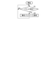
パケット処理装置10について、図2を用いてさらに説明する。図2は、パケット処理装置10の機能構成を示すブロック図である。なお、図2おける図1と同様の要素については同一の符号を付している。パケット処理装置10は、第1受信部101、集約バッファー102、周期管理部103、結合部104、範囲選択部105、暗号化部106、第1送信部107、第2受信部108、復号部109、分割部110及び第2送信部111を含む。 The packet processing device 10 will be further described with reference to FIG. FIG. 2 is a block diagram showing a functional configuration of the packet processing device 10. The same elements as those in FIG. 1 in FIG. 2 are designated by the same reference numerals. The packet processing device 10 includes a first receiving unit 101, an aggregation buffer 102, a cycle management unit 103, a coupling unit 104, a range selection unit 105, an encryption unit 106, a first transmitting unit 107, a second receiving unit 108, and a decoding unit 109. , The division unit 110 and the second transmission unit 111 are included.

第1受信部101は、クライアント装置30などから送信された個別パケットを受信する。例えば、第1の通信I/F15が、第1受信部101として機能する。 The first receiving unit 101 receives individual packets transmitted from the client device 30 and the like. For example, the first communication I / F 15 functions as the first receiving unit 101.

集約バッファー102は、第1受信部101によって受信された個別パケットを記憶する。例えば、RAM13又は補助記憶デバイス14が集約バッファー102として機能する。 The aggregation buffer 102 stores the individual packets received by the first receiving unit 101. For example, the RAM 13 or the auxiliary storage device 14 functions as the aggregation buffer 102.

周期管理部103は、一定周期ごとに集約バッファー102から個別パケットを取り出す。例えば、プロセッサー11が周期管理部103として機能する。 The cycle management unit 103 takes out individual packets from the aggregation buffer 102 at regular intervals. For example, the processor 11 functions as a cycle management unit 103.

結合部104は、周期管理部103によって取り出された複数の個別パケットを結合して集約する。結合部104は、集約パケットを生成する。例えば、プロセッサー11が結合部104として機能する。 The coupling unit 104 combines and aggregates a plurality of individual packets taken out by the cycle management unit 103. The coupling unit 104 generates an aggregate packet. For example, the processor 11 functions as a coupling portion 104.

範囲選択部105は、集約パケットのうちの暗号化する範囲を決定して選択する。例えば、プロセッサー11が範囲選択部105として機能する。 The range selection unit 105 determines and selects the range to be encrypted in the aggregated packet. For example, the processor 11 functions as a range selection unit 105.

暗号化部106は、集約パケットを暗号化する。また、暗号化部106は、集約パケットの暗号化と共に、当該集約パケットのMAC(message authentication code)値を生成する。MAC値は、集約パケットの改竄検出など、集約パケットのデータの完全性の検証に用いられる。例えば、プロセッサー11が暗号化部106として機能する。MAC値は、データの完全性を保証するための符号の一例である。 The encryption unit 106 encrypts the aggregated packet. Further, the encryption unit 106 generates the MAC (message authentication code) value of the aggregated packet together with the encryption of the aggregated packet. The MAC value is used to verify the integrity of the aggregated packet data, such as detecting tampering with the aggregated packet. For example, the processor 11 functions as an encryption unit 106. The MAC value is an example of a code for guaranteeing data integrity.

第1送信部107は、周期管理部103、範囲選択部105、結合部104及び暗号化部106によって生成された集約パケットをサーバー装置20などに送信する。例えば、第2の通信I/F16が、第1送信部107として機能する。 The first transmission unit 107 transmits the aggregated packets generated by the cycle management unit 103, the range selection unit 105, the coupling unit 104, and the encryption unit 106 to the server device 20 and the like. For example, the second communication I / F 16 functions as the first transmission unit 107.

第2受信部108は、サーバー装置20などから集約パケットを受信する。例えば、第2の通信I/F16が、第2受信部108として機能する。 The second receiving unit 108 receives the aggregated packet from the server device 20 or the like. For example, the second communication I / F 16 functions as the second receiving unit 108.

復号部109は、第2受信部によって受信された集約パケットの暗号化された部分を復号する。また、復号部109は、当該集約パケットに含まれるMAC値を用いてデータの完全性の検証を行う。さらに、復号部109は、集約パケットが改竄されたことなどによりデータの完全性の保証が得られなかった場合には、当該集約パケットを破棄する。例えば、プロセッサー11が復号部109として機能する。 The decryption unit 109 decodes the encrypted portion of the aggregated packet received by the second reception unit. Further, the decoding unit 109 verifies the integrity of the data using the MAC value included in the aggregated packet. Further, the decoding unit 109 discards the aggregated packet when the integrity of the data cannot be guaranteed due to falsification of the aggregated packet or the like. For example, the processor 11 functions as a decoding unit 109.

分割部110は、第2受信部によって受信された集約パケットを個々の個別パケットに分割する。例えば、プロセッサー11が分割部110として機能する。 The dividing unit 110 divides the aggregated packet received by the second receiving unit into individual individual packets. For example, the processor 11 functions as a dividing unit 110.

第2送信部111は、分割部110によって分割された個々の個別パケットのそれぞれを、それぞれの個別パケットの宛先であるクライアント装置30などに送信する。例えば、第1の通信I/F15が、第2送信部111として機能する。 The second transmission unit 111 transmits each of the individual individual packets divided by the division unit 110 to the client device 30 or the like, which is the destination of each individual packet. For example, the first communication I / F 15 functions as the second transmission unit 111.

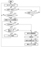
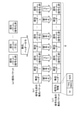
以下、第1実施形態に係る通信システム1の動作を図3~図8に基づいて説明する。なお、以下の動作説明における処理の内容は一例であって、同様な結果を得ることが可能な様々な処理を適宜に利用できる。図3~図5は、パケット処理装置10のプロセッサー11による処理のフローチャートである。プロセッサー11は、ROM12又は補助記憶デバイス14などに記憶されたプログラムに基づいてこの処理を実行する。なお、プロセッサー11は、図3~図5に示す処理を並行又は並列して処理する。図6~8は、サーバー装置20のプロセッサー21による処理のフローチャートである。プロセッサー21は、ROM22又は補助記憶デバイス24などに記憶されたプログラムに基づいてこの処理を実行する。なお、プロセッサー21は、図6~図8に示す処理を並行又は並列して処理する。また、特に説明が無い限り、プロセッサー11及びプロセッサー21は、ステップS(m)(mは、自然数。)の処理の後、ステップS(m+1)へと進むものとする。 Hereinafter, the operation of the communication system 1 according to the first embodiment will be described with reference to FIGS. 3 to 8. The content of the process in the following operation description is an example, and various processes that can obtain the same result can be appropriately used. 3 to 5 are flowcharts of processing by the processor 11 of the packet processing device 10. The processor 11 executes this process based on a program stored in the ROM 12 or the auxiliary storage device 14. The processor 11 processes the processes shown in FIGS. 3 to 5 in parallel or in parallel. 6 to 8 are flowcharts of processing by the processor 21 of the server device 20. The processor 21 executes this process based on a program stored in the ROM 22 or the auxiliary storage device 24 or the like. The processor 21 processes the processes shown in FIGS. 6 to 8 in parallel or in parallel. Further, unless otherwise specified, the processor 11 and the processor 21 are assumed to proceed to step S (m + 1) after the processing of step S (m) (m is a natural number).

複数のクライアント装置30のそれぞれは、サーバー装置20を宛先とするデータを送信する。当該データは、個別パケットとして送信される。当該個別パケットは、ネットワークNW1を介してパケット処理装置10によって受信される。
図3のステップS1においてプロセッサー11は、第1の通信I/F15(第1受信部101)によって、クライアント装置30から送信された個別パケットが受信されるのを待ち受けている。プロセッサー11は、個別パケットが受信されたならば、ステップS1においてYesと判定してステップS2へと進む。
Each of the plurality of client devices 30 transmits data destined for the server device 20. The data is transmitted as an individual packet. The individual packet is received by the packet processing device 10 via the network NW1.
In step S1 of FIG. 3, the processor 11 waits for the individual packet transmitted from the client device 30 to be received by the first communication I / F 15 (first receiving unit 101). If the individual packet is received, the processor 11 determines Yes in step S1 and proceeds to step S2.

ステップS2においてプロセッサー11は、ステップS1で受信された個別パケットを集約バッファー102に記憶させる。プロセッサー11は、ステップS2の後、ステップS1へと戻る。
以上のようにして、第1の通信I/F15によって受信された個別パケットが次々と集約バッファー102に蓄積記憶されていく。
In step S2, the processor 11 stores the individual packets received in step S1 in the aggregation buffer 102. The processor 11 returns to step S1 after step S2.
As described above, the individual packets received by the first communication I / F 15 are accumulated and stored in the aggregation buffer 102 one after another.

一方、図4のステップS11においてパケット処理装置10のプロセッサー11(周期管理部103)は、第1のタイマーをリセットする。第1のタイマーは、パケット処理装置10が前回集約パケットを送信してからの経過時間を計測するためのタイマーである。なお、集約パケットについては、後述する。 On the other hand, in step S11 of FIG. 4, the processor 11 (cycle management unit 103) of the packet processing device 10 resets the first timer. The first timer is a timer for measuring the elapsed time since the packet processing device 10 transmitted the aggregated packet last time. The aggregated packet will be described later.

ステップS12においてプロセッサー11(周期管理部103)は、第1のタイマーをリセットしてから時間T1以上経過したか否かを判定する。なお、時間T1は、例えば、パケット処理装置10の管理者などによって予め設定される。あるいは、時間T1は、パケット処理装置10の設計者などによって予め定められていてもよい。プロセッサー11は、第1のタイマーをリセットしてから時間T1が経過していないならば、ステップS12においてNoと判定してステップS13へと進む。 In step S12, the processor 11 (cycle management unit 103) determines whether or not the time T1 or more has elapsed since the first timer was reset. The time T1 is set in advance by, for example, the administrator of the packet processing device 10. Alternatively, the time T1 may be predetermined by the designer of the packet processing device 10 or the like. If the time T1 has not elapsed since the first timer was reset, the processor 11 determines No in step S12 and proceeds to step S13.

ステップS13においてプロセッサー11は、集約バッファー102に記憶された未送信の個別パケットのデータ容量の合計が容量D1以上であるか否かを判定する。なお、容量D1は、例えば、パケット処理装置10の管理者などによって予め設定される。あるいは、容量D1は、パケット処理装置10の設計者などによって予め定められていてもよい。容量D1は、例えば、パケット処理装置10が生成する集約パケットのMTU(maximum transmission unit)である。プロセッサー11は、集約バッファー102に記憶された未送信の個別パケットのデータ容量の合計が容量D1以上でないならば、ステップS13においてNoと判定してステップS12へと戻る。かくして、プロセッサー11は、第1のタイマーをリセットしてから時間T1が経過したか、集約バッファー102に記憶された未送信の個別パケットのデータ容量の合計が容量D1以上となるまでステップS12及びステップS13を繰り返す。すなわち、ステップS12の処理により、一定周期ごとにステップS14~ステップS22の処理が繰り返される。 In step S13, the processor 11 determines whether or not the total data capacity of the untransmitted individual packets stored in the aggregation buffer 102 is equal to or greater than the capacity D1. The capacity D1 is set in advance by, for example, the administrator of the packet processing device 10. Alternatively, the capacity D1 may be predetermined by the designer of the packet processing device 10 or the like. The capacity D1 is, for example, an MTU (maximum transmission unit) of aggregated packets generated by the packet processing device 10. If the total data capacity of the untransmitted individual packets stored in the aggregation buffer 102 is not equal to or larger than the capacity D1, the processor 11 determines No in step S13 and returns to step S12. Thus, the processor 11 steps S12 and steps until the time T1 has elapsed since the first timer was reset or the total data capacity of the untransmitted individual packets stored in the aggregation buffer 102 becomes the capacity D1 or more. Repeat S13. That is, the processing of step S12 repeats the processing of steps S14 to S22 at regular intervals.

プロセッサー11は、ステップS12及びステップS13の待受状態にあるときに、第1のタイマーをリセットしてから時間T1が経過したならば、ステップS12においてYesと判定してステップS14へと進む。 If the time T1 has elapsed since the first timer was reset while the processor 11 is in the standby state of step S12 and step S13, the processor 11 determines Yes in step S12 and proceeds to step S14.

ステップS14においてプロセッサー11(周期管理部103)は、集約バッファー102に未送信の個別パケットが記憶されているか否かを判定する。プロセッサー11は、集約バッファー102に未送信の個別パケットが記憶されていないならば、ステップS14においてNoと判定してステップS11へと戻る。すなわち、プロセッサー11は、前回集約パケットを送信してから時間T1が経過しても未送信の個別パケットが集約バッファー102に記憶されなかったならば、第1のタイマーをリセットする。対して、プロセッサー11は、集約バッファー102に未送信の個別パケットが記憶されているならば、ステップS14においてYesと判定してステップS15へと進む。
また、プロセッサー11は、ステップS12及びステップS13の待受状態にあるときに集約バッファー102に記憶された未送信の個別パケットのデータ容量の合計が容量D1以上であるならば、ステップS13においてYesと判定してステップS15へと進む。
In step S14, the processor 11 (cycle management unit 103) determines whether or not an untransmitted individual packet is stored in the aggregation buffer 102. If the aggregate buffer 102 does not store an untransmitted individual packet, the processor 11 determines No in step S14 and returns to step S11. That is, if the untransmitted individual packet is not stored in the aggregation buffer 102 even after the time T1 has elapsed since the last aggregation packet was transmitted, the processor 11 resets the first timer. On the other hand, if the untransmitted individual packet is stored in the aggregation buffer 102, the processor 11 determines Yes in step S14 and proceeds to step S15.
Further, if the total data capacity of the untransmitted individual packets stored in the aggregation buffer 102 in the standby state of step S12 and step S13 is equal to or larger than the capacity D1, the processor 11 indicates Yes in step S13. The determination is made and the process proceeds to step S15.

ステップS15においてプロセッサー11(周期管理部103)は、集約バッファー102に記憶された未送信の個別パケット1個を取り出す。ここで、プロセッサー11は、個別パケットを取り出すとき、集約バッファー102に記憶された当該個別パケットが送信済みであることが分かるようにする。あるいは、プロセッサー11は、当該個別パケットを集約バッファーから削除する。当該個別パケットは、例えば、集約バッファー102に記憶されている未送信の個別パケットの中で最初に記憶された個別パケットである。そして、ステップS15においてプロセッサー11(結合部104)は、取り出したパケットを含む集約パケットを生成する。ここで生成される集約パケットの一例について、図9を用いて説明する。図9は、第1実施形態に係る集約パケットの一例を説明するための図である。なお、図9には、n個の個別パケットが集約された集約パケットが示されているが、ステップS15で生成される集約パケットに含まれる個別パケットは1つである。すなわち、n=1である。n=1の集約パケットには複数の個別パケットが含まれているわけではないが、便宜上集約パケットと称するものとする。なお、nは、1以上の自然数である。 In step S15, the processor 11 (cycle management unit 103) takes out one untransmitted individual packet stored in the aggregation buffer 102. Here, when the individual packet is taken out, the processor 11 makes it known that the individual packet stored in the aggregation buffer 102 has been transmitted. Alternatively, the processor 11 deletes the individual packet from the aggregate buffer. The individual packet is, for example, the first individual packet stored in the untransmitted individual packet stored in the aggregation buffer 102. Then, in step S15, the processor 11 (coupling unit 104) generates an aggregated packet including the fetched packet. An example of the aggregated packet generated here will be described with reference to FIG. FIG. 9 is a diagram for explaining an example of the aggregated packet according to the first embodiment. Note that FIG. 9 shows an aggregated packet in which n individual packets are aggregated, but the aggregated packet generated in step S15 contains only one individual packet. That is, n = 1. Although the aggregated packet of n = 1 does not include a plurality of individual packets, it is referred to as an aggregated packet for convenience. Note that n is a natural number of 1 or more.

図9に示すように、プロセッサー11は、複数の個別パケット(a1)の集約、及び複数の個別パケット(a1)に対するヘッダーの付与を行うことで、集約パケット(b1)を生成する。なお、個別パケット(a1)のそれぞれは、例えば、ペイロードである。n個の個別パケットが集約された集約パケットは、集約ヘッダー、n個の個別ヘッダー及びn個の個別パケットを含む。n個の個別ヘッダー及びn個の個別パケットは、集約ヘッダーの後に続く。
集約ヘッダーは、集約パケットに含まれる個別パケットの数などの、集約パケット全体に関する情報を含む。
n個の個別ヘッダーのそれぞれは、n個の個別パケットのそれぞれに対して1対1で関連付けられる。すなわち、例えば、個別ヘッダーkと個別パケットkとが関連付けられる。ただし、kはn以下の自然数である。それぞれの個別ヘッダーは、集約パケットを個々の個別パケットに分割できるように、関連付けられた個別パケットのサイズなどの、関連付けられた個別パケットについての情報を含む。また、集約パケット(b1)は、個別ヘッダーk、個別パケットk、個別ヘッダーk+1、個別パケットk+1、…のような順で、並んでいる。関連付けられた個別ヘッダーと個別パケットの組が隣り合うように並んでいる。
ステップS15では、n=1であるため、ステップS15で生成される集約パケットには、集約ヘッダー、個別ヘッダー1及び個別パケット1が含まれる。
As shown in FIG. 9, the processor 11 generates an aggregated packet (b1) by aggregating a plurality of individual packets (a1) and adding a header to the plurality of individual packets (a1). Each of the individual packets (a1) is, for example, a payload. The aggregated packet in which n individual packets are aggregated includes an aggregate header, n individual headers, and n individual packets. The n individual headers and n individual packets follow the aggregate header.
The aggregate header contains information about the entire aggregate packet, such as the number of individual packets contained in the aggregate packet.
Each of the n individual headers is associated one-to-one with each of the n individual packets. That is, for example, the individual header k and the individual packet k are associated with each other. However, k is a natural number of n or less. Each individual header contains information about the associated individual packet, such as the size of the associated individual packet, so that the aggregated packet can be split into individual individual packets. Further, the aggregated packets (b1) are arranged in the order of individual header k, individual packet k, individual header k + 1, individual packet k + 1, .... Pairs of associated individual headers and individual packets are lined up next to each other.
Since n = 1 in step S15, the aggregated packet generated in step S15 includes the aggregated header, the individual header 1, and the individual packet 1.

ステップS16においてプロセッサー11(結合部104)は、集約バッファー102に未送信の個別パケットが記憶されているか否かを判定する。プロセッサー11は、集約バッファー102に未送信の個別パケットが記憶されているならば、ステップS16においてYesと判定してステップS17へと進む。 In step S16, the processor 11 (coupling unit 104) determines whether or not an untransmitted individual packet is stored in the aggregation buffer 102. If the aggregate buffer 102 stores untransmitted individual packets, the processor 11 determines Yes in step S16 and proceeds to step S17.

ステップS17においてプロセッサー11(結合部104)は、集約パケットに次の個別パケットを結合した場合の集約パケットのデータ容量が、パケット処理装置10が生成する集約パケットの最大データ容量以下となるか否かを判定する。なお、次の個別パケットとは、次に集約の対象となる個別パケットである。例えば、次の個別パケットは、集約バッファー102に記憶されている未送信の個別パケットの中で最初に記憶された個別パケットである。また、パケット処理装置10が生成する集約パケットの最大データ容量は、例えば、パケット処理装置10の管理者又は設計者などによって予め定められる。あるいは、パケット処理装置10が生成する集約パケットの最大データ容量は、パケット処理装置10が自動的に決定する。パケット処理装置10が生成する集約パケットの最大データ容量は、パケット処理装置10などのMTUであっても良い。プロセッサー11は、次の個別パケットを結合した場合の集約パケットのデータ容量が、当該集約パケットの最大データ容量以下となるならば、ステップS17においてYesと判定してステップS18へと進む。 In step S17, the processor 11 (coupling unit 104) determines whether or not the data capacity of the aggregated packet when the next individual packet is combined with the aggregated packet is equal to or less than the maximum data capacity of the aggregated packet generated by the packet processing device 10. Is determined. The next individual packet is an individual packet to be aggregated next. For example, the next individual packet is the first untransmitted individual packet stored in the aggregation buffer 102. Further, the maximum data capacity of the aggregated packet generated by the packet processing device 10 is predetermined by, for example, the administrator or the designer of the packet processing device 10. Alternatively, the packet processing device 10 automatically determines the maximum data capacity of the aggregated packet generated by the packet processing device 10. The maximum data capacity of the aggregated packet generated by the packet processing device 10 may be an MTU such as the packet processing device 10. If the data capacity of the aggregated packet when the next individual packet is combined is equal to or less than the maximum data capacity of the aggregated packet, the processor 11 determines Yes in step S17 and proceeds to step S18.

ステップS18においてプロセッサー11(結合部104)は、集約バッファー102から次のパケットを取り出して、当該次のパケットを集約パケットに結合する。これにより、集約パケットに含まれる個別パケットの数が1つ増える。ここで、プロセッサー11は、個別パケットを取り出すとき、集約バッファー102に記憶された当該個別パケットが送信済みであることが分かるようにする。あるいは、プロセッサー11は、当該個別パケットを集約バッファーから削除する。 In step S18, the processor 11 (coupling unit 104) extracts the next packet from the aggregation buffer 102 and combines the next packet into the aggregation packet. This increases the number of individual packets contained in the aggregated packet by one. Here, when the individual packet is taken out, the processor 11 makes it known that the individual packet stored in the aggregation buffer 102 has been transmitted. Alternatively, the processor 11 deletes the individual packet from the aggregate buffer.

プロセッサー11は、集約バッファー102に未送信の個別パケットが記憶されていないならば、ステップS16においてNoと判定してステップS19へと進む。また、プロセッサー11は、次の個別パケットを結合した場合の集約パケットのデータ容量がパケット処理装置10のMTUを超えるならば、ステップS17においてNoと判定してステップS19へと進む。
かくして、プロセッサー11は、集約バッファー102に未送信の個別パケットが記憶されていない状態になるか、次の個別パケットを結合した場合の集約パケットのデータ容量がパケット処理装置10のMTUを超えるまで、ステップS16~ステップS18を繰り返す。これにより、(ステップS18の処理を行った回数+1)個の個別パケットが集約された集約パケットが生成される。
If the aggregate buffer 102 does not store an untransmitted individual packet, the processor 11 determines No in step S16 and proceeds to step S19. If the data capacity of the aggregated packet when the next individual packet is combined exceeds the MTU of the packet processing device 10, the processor 11 determines No in step S17 and proceeds to step S19.
Thus, the processor 11 is in a state where the untransmitted individual packet is not stored in the aggregation buffer 102, or until the data capacity of the aggregation packet when the next individual packet is combined exceeds the MTU of the packet processing device 10. Steps S16 to S18 are repeated. As a result, an aggregated packet is generated in which (the number of times the process of step S18 is performed + 1) individual packets are aggregated.

ステップS19においてプロセッサー11(範囲選択部105)は、ステップS15~ステップS18の処理によって生成された集約パケットについて、暗号化する範囲を決定する。暗号化する範囲は、集約パケットのうちの暗号化されていない部分である。ステップS19の処理は、範囲選択部105によって行われる。
ここで、個別パケットは、暗号化済みの場合と、平文の場合がある。したがって、暗号化済みの個別パケットに対してさらに暗号化すると、二重に暗号化されることとなってしまう。二重に暗号化した場合、二重に暗号化しなかった場合と比べて暗号化にかかる時間と復号にかかる時間が長くなり、また、処理負荷も大きくなる。このため、プロセッサー11は、個別パケットについては、平文のもののみを暗号化することが好ましい。また、集約ヘッダー及び個別ヘッダーについては、ステップS15又はステップS18で付与したものであり、暗号化されていない。したがって、集約ヘッダー及び個別ヘッダーについては、暗号化することが好ましい。なお、プロセッサー11は、それぞれの個別パケットが暗号化済みであるか否かについて、例えば、当該個別パケットの送信元であるクライアント装置30から送信される情報により知ることができる。プロセッサー11は、暗号化済みであるか否かが分からない個別パケットがある場合には、当該パケットを暗号化されているものとみなして暗号化しない。あるいは、プロセッサー11は、暗号化済みであるか否かが分からない個別パケットがある場合には、当該パケットは暗号化されていないものとみなして暗号化する。あるいは、プロセッサー11は、個別パケットが暗号化済みであるか否かの判定を行わずに、集約ヘッダー及び個別ヘッダーを含み、個別パケットを含まない範囲を暗号化の範囲として決定しても良い。これは、例えば、全ての個別パケットがクライアント装置30などで暗号化されているような通信システム1において有用である。また、プロセッサー11は、集約パケットに含まれる個別パケットのうちの暗号化済みのパケットが占める割合が予め定められた割合以下の場合には、暗号化済みの個別パケットを含めて集約パケット全体を暗号化しても良い。集約パケットに占める暗号化済みの個別パケットの割合が小さい場合には、集約パケット全体を暗号化した方が、集約パケットのうちの暗号化済みでない部分だけを暗号化するより負荷が小さくなる可能性がある。
以上より、プロセッサー11は、暗号化前の集約パケットについて、集約ヘッダー、個別ヘッダー、及び平文の個別パケットを暗号化範囲として決定する。なお、図9には、暗号化済みである個別パケット1と、平文である個別パケット2を含む場合について例示している。したがって、図9に示す集約パケット(b1)を暗号化する範囲は、集約ヘッダー、個別ヘッダー、及び個別パケット2を含む。
In step S19, the processor 11 (range selection unit 105) determines the range to be encrypted for the aggregated packet generated by the processes of steps S15 to S18. The scope to be encrypted is the unencrypted part of the aggregated packet. The process of step S19 is performed by the range selection unit 105.
Here, the individual packet may be encrypted or may be in plain text. Therefore, if the individual packet that has been encrypted is further encrypted, it will be doubly encrypted. In the case of double encryption, the time required for encryption and the time required for decryption become longer than in the case of not performing double encryption, and the processing load also increases. Therefore, it is preferable that the processor 11 encrypts only plain text packets. Further, the aggregate header and the individual header are added in step S15 or step S18, and are not encrypted. Therefore, it is preferable to encrypt the aggregate header and the individual header. The processor 11 can know whether or not each individual packet has been encrypted, for example, from the information transmitted from the client device 30 that is the source of the individual packet. When there is an individual packet for which it is unknown whether or not it has been encrypted, the processor 11 considers the packet to be encrypted and does not encrypt the packet. Alternatively, if there is an individual packet for which it is unknown whether or not it has been encrypted, the processor 11 considers the packet to be unencrypted and encrypts the packet. Alternatively, the processor 11 may determine the range including the aggregate header and the individual header and not including the individual packet as the encryption range without determining whether or not the individual packet has been encrypted. This is useful, for example, in communication system 1 in which all individual packets are encrypted by the client device 30 or the like. Further, when the ratio of the encrypted packet among the individual packets included in the aggregated packet is less than or equal to a predetermined ratio, the processor 11 encrypts the entire aggregated packet including the encrypted individual packet. It may be converted. If the percentage of individual encrypted packets in the aggregated packet is small, encrypting the entire aggregated packet may be less expensive than encrypting only the unencrypted part of the aggregated packet. There is.
From the above, the processor 11 determines the aggregated header, the individual header, and the plaintext individual packet as the encryption range for the aggregated packet before encryption. Note that FIG. 9 illustrates a case where the encrypted individual packet 1 and the plain text individual packet 2 are included. Therefore, the range for encrypting the aggregated packet (b1) shown in FIG. 9 includes the aggregated header, the individual header, and the individual packet 2.

ステップS20においてプロセッサー11(暗号化部106)は、ステップS19で決定した範囲を暗号化する。なお、プロセッサー11は、暗号化する範囲以外については、暗号化の必要がないので、図9に示すようにコピーする。また、プロセッサー11は、暗号化とともに、MAC値の計算を行う。MAC値の計算範囲は、例えば、暗号化の範囲であっても良いし、集約パケット全体であっても良い。また、プロセッサー11は、集約前の個別パケットの一部又は全部にMAC値が付与されている場合には、暗号化の場合と同様に、MAC値が付与されていない個別パケット、集約ヘッダー及び個別ヘッダーに対してMAC値の計算を行っても良い。
プロセッサー11は、暗号化に、例えばAES(Advanced Encryption Standard)又はその他の暗号を用いる。また、プロセッサー11は、MAC値の計算に、例えばHMAC(hash-based message authentication code)、GMAC(Galois Message Authentication Code)又はその他のMAC値計算方法を用いる。また、プロセッサー11は、暗号化の範囲とMAC値の計算範囲が同一の場合には、CCM(Counter with CBC-MAC)、GCM(Galois/Counter Mode)又はその他の認証付き暗号モードを用いることができる。認証付き暗号モードを用いることで、セキュリティ性の向上と、暗号化及びMAC値の計算の効率化とが期待できる。
なお、暗号化に利用する共通鍵又はMAC値の計算に利用する共通鍵は、例えば、通信セッションの確立時に鍵交換を行って共有しても良いし、予め各ノードの記憶装置に共通鍵を保存しておき、その鍵を利用しても良い。鍵交換を行う場合には、ディフィー・ヘルマン鍵交換又はその他の鍵交換方法を利用する。
なお、プロセッサー11は、1つの集約パケット内における、パケット処理装置10において暗号化する部分については、全て同一の暗号鍵を用いて良い。
ステップS19及びステップS20の処理が行われることで、集約パケットのうちの暗号化済みでないと判定された範囲が暗号化される。
In step S20, the processor 11 (encryption unit 106) encrypts the range determined in step S19. Since the processor 11 does not need to be encrypted except for the range to be encrypted, it is copied as shown in FIG. Further, the processor 11 calculates the MAC value together with the encryption. The calculation range of the MAC value may be, for example, the range of encryption or the entire aggregated packet. Further, when the MAC value is given to a part or all of the individual packets before aggregation, the processor 11 sets the individual packets, the aggregation header and the individual packets to which the MAC value is not given, as in the case of encryption. The MAC value may be calculated for the header.
The processor 11 uses, for example, AES (Advanced Encryption Standard) or other encryption for encryption. Further, the processor 11 uses, for example, HMAC (hash-based message authentication code), GMAC (Galois Message Authentication Code), or another MAC value calculation method for calculating the MAC value. Further, when the encryption range and the calculation range of the MAC value are the same, the processor 11 may use CCM (Counter with CBC-MAC), GCM (Galois / Counter Mode) or other authenticated encryption modes. can. By using the encrypted mode with authentication, it is expected that the security will be improved and the efficiency of encryption and calculation of the MAC value will be improved.
The common key used for encryption or the common key used for calculating the MAC value may be shared by exchanging keys when establishing a communication session, or the common key may be stored in the storage device of each node in advance. You may save it and use the key. When exchanging keys, use Diffie-Hellmann key exchange or other key exchange methods.
The processor 11 may use the same encryption key for all the parts to be encrypted by the packet processing device 10 in one aggregate packet.
By performing the processes of steps S19 and S20, the range of the aggregated packets determined to be unencrypted is encrypted.

以上より、集約される個別パケットに暗号化済みの個別パケットが含まれる場合、当該暗号化に使われた暗号鍵とパケット処理装置10において暗号化された部分に使われた暗号鍵は異なることとなる。 From the above, when the individual packets to be aggregated include encrypted individual packets, the encryption key used for the encryption and the encryption key used for the encrypted part in the packet processing device 10 are different. Become.

ステップS21においてプロセッサー11(暗号化部106)は、暗号化情報を生成する。そして、プロセッサー11は、生成した当該暗号化情報を集約パケットに付与する。
暗号化情報は、IV(initialization vector)、TAG及びSIZEを含む。IVは、ステップS19の暗号化に用いられた初期化ベクトルである。TAGは、ステップS19において求められたMAC値である。SIZEは、暗号化情報の後に続くデータ範囲Rのデータサイズを示す。ただし、IVを認証などの別の方法で交換する場合には、プロセッサー11は、必ずしも毎回暗号化情報にIVを含める必要は無い。
ステップS19~ステップS21の処理によって、図9に示すように、暗号化前の集約パケット(b1)に基づいて暗号化後の集約パケット(c1)が生成される。
In step S21, the processor 11 (encryption unit 106) generates encryption information. Then, the processor 11 adds the generated encryption information to the aggregated packet.
The encrypted information includes IV (initialization vector), TAG and SIZE. IV is the initialization vector used for the encryption in step S19. TAG is the MAC value obtained in step S19. SIZE indicates the data size of the data range R following the encrypted information. However, when exchanging the IV by another method such as authentication, the processor 11 does not necessarily have to include the IV in the encrypted information every time.
By the processing of steps S19 to S21, as shown in FIG. 9, the aggregated packet (c1) after encryption is generated based on the aggregated packet (b1) before encryption.

ステップS22においてプロセッサー11は、ステップS15~ステップS21の処理によって生成された暗号化後の集約パケットをサーバー装置20に送信するように、第2の通信I/F16(第1送信部107)に対して指示する。この指示を受けて第2の通信I/F16は、当該集約パケットをサーバー装置20に送信する。送信された当該集約パケットは、サーバー装置20の通信I/F25によって受信される。プロセッサー11は、ステップS22の処理の後、ステップS11へと戻る。 In step S22, the processor 11 informs the second communication I / F 16 (first transmission unit 107) so as to transmit the encrypted aggregate packet generated by the processes of steps S15 to S21 to the server device 20. To instruct. In response to this instruction, the second communication I / F 16 transmits the aggregated packet to the server device 20. The transmitted aggregated packet is received by the communication I / F 25 of the server device 20. The processor 11 returns to step S11 after the processing of step S22.

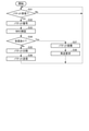
一方、図6のステップS101においてサーバー装置20のプロセッサー21は、通信I/F25によって集約パケットが受信されるのを待ち受けている。プロセッサー21は、集約パケットが受信されたならば、ステップS101においてYesと判定してステップS102へと進む。 On the other hand, in step S101 of FIG. 6, the processor 21 of the server device 20 waits for the aggregated packet to be received by the communication I / F 25. If the aggregated packet is received, the processor 21 determines Yes in step S101 and proceeds to step S102.

ステップS102においてプロセッサー21は、ステップS101で受信された集約パケットを復号する。
ステップS103においてプロセッサー21は、ステップS101で受信された集約パケットのMAC値を検証する。すなわち、プロセッサー21は、集約パケットのMAC値を計算し、集約パケットに含まれるMAC値と一致するか否かを検証する。
なお、集約パケットが認証付き暗号モードで暗号化されている場合、プロセッサー21は、ステップS102とステップS103を同時に行うこととなる。
In step S102, the processor 21 decodes the aggregated packet received in step S101.
In step S103, the processor 21 verifies the MAC value of the aggregated packet received in step S101. That is, the processor 21 calculates the MAC value of the aggregated packet and verifies whether or not it matches the MAC value included in the aggregated packet.
When the aggregated packet is encrypted in the authenticated encryption mode, the processor 21 performs step S102 and step S103 at the same time.

ステップS104においてプロセッサー21は、集約パケットのデータの完全性が保証されているか否かを判定する。プロセッサー21は、ステップS103のMAC値の検証においてMAC値が一致したならば、ステップS104においてNoと判定してステップS105へと進む。 In step S104, the processor 21 determines whether or not the data integrity of the aggregated packet is guaranteed. If the MAC values match in the verification of the MAC value in step S103, the processor 21 determines No in step S104 and proceeds to step S105.

ステップS105においてプロセッサー21は、集約パケットの各ヘッダーに含まれる情報などに基づき、集約パケットを個々の個別パケットに分割する。 In step S105, the processor 21 divides the aggregated packet into individual individual packets based on the information included in each header of the aggregated packet.

ステップS106においてプロセッサー21は、ステップS105において分割された個別パケットのそれぞれを処理バッファーに登録する。プロセッサー21は、ステップS106の処理の後、ステップS101へと戻る。 In step S106, the processor 21 registers each of the individual packets divided in step S105 in the processing buffer. The processor 21 returns to step S101 after the processing of step S106.

対して、プロセッサー21は、ステップS103のMAC値の検証においてMAC値が一致しなかったならば、ステップS104においてYesと判定してステップS107へと進む。例えば、集約パケットが改竄されていた場合など、データが書き換わっていた場合に、MAC値が一致しなくなる。
ステップS107においてプロセッサー21は、ステップS101で受信された集約パケットを破棄する。
On the other hand, if the MAC values do not match in the verification of the MAC value in step S103, the processor 21 determines Yes in step S104 and proceeds to step S107. For example, when the data is rewritten, such as when the aggregated packet has been tampered with, the MAC values do not match.
In step S107, the processor 21 discards the aggregated packet received in step S101.

ステップS108においてプロセッサー21は、集約パケット全体の再送をパケット処理装置10に要求する。プロセッサー21は、ステップS108の処理の後、ステップS101へと戻る。 In step S108, the processor 21 requests the packet processing device 10 to retransmit the entire aggregated packet. The processor 21 returns to step S101 after the processing of step S108.

また、図7のステップS111においてプロセッサー21は、処理バッファーに未処理パケットが記憶されているか否かを判定する。プロセッサー21は、処理バッファーに未処理パケットが記憶されているならば、ステップS111においてYesと判定してステップS112へと進む。対して、プロセッサー21は、処理バッファーに未処理パケットが記憶されていないならば、ステップS111においてNoと判定してステップS111を繰り返す。 Further, in step S111 of FIG. 7, the processor 21 determines whether or not an unprocessed packet is stored in the processing buffer. If the unprocessed packet is stored in the processing buffer, the processor 21 determines Yes in step S111 and proceeds to step S112. On the other hand, if the unprocessed packet is not stored in the processing buffer, the processor 21 determines No in step S111 and repeats step S111.

ステップS112においてプロセッサー21は、処理バッファーから未処理パケット1個を取り出し、当該未処理パケットに基づく処理を行う。プロセッサー21は、未処理パケットを取り出すとき、処理バッファーに記憶された当該未処理パケットが処理済みであることが分かるようにする。あるいは、プロセッサー21は、当該未処理パケットを処理バッファーから削除する。当該未処理パケットは、例えば、処理バッファーに記憶されている未処理パケットの中で最初に記憶された未処理パケットである。ここでの処理は、従来のサーバー装置が、クライアント装置30から送信された、集約されていない状態の個別パケットを受信して、当該個別パケットに基づいて行う処理と同様である。 In step S112, the processor 21 takes out one unprocessed packet from the processing buffer and performs processing based on the unprocessed packet. When the processor 21 retrieves an unprocessed packet, the processor 21 makes it known that the unprocessed packet stored in the processing buffer has been processed. Alternatively, the processor 21 deletes the unprocessed packet from the processing buffer. The unprocessed packet is, for example, the first unprocessed packet stored in the unprocessed packet stored in the processing buffer. The process here is the same as the process in which the conventional server device receives the individual packet in the unaggregated state transmitted from the client device 30 and performs the process based on the individual packet.

ステップS113においてプロセッサー21は、ステップS112の処理内容に基づき、必要に応じて、ステップS112で取り出した個別パケットの送信元であるクライアント装置30に対して返信する応答を生成する。 In step S113, the processor 21 generates a response to be returned to the client device 30 which is the source of the individual packet taken out in step S112, if necessary, based on the processing content of step S112.

ステップS114においてプロセッサー21は、ステップS113において応答を生成した場合には、当該応答をパケットとしてサーバー集約バッファーに登録する。プロセッサー21は、ステップS114の処理の後、ステップS111へと戻る。 When the processor 21 generates a response in step S113, the processor 21 registers the response as a packet in the server aggregation buffer. The processor 21 returns to step S111 after the processing of step S114.

また、図8のステップS121においてプロセッサー21は、第2のタイマーをリセットする。第2のタイマーは、サーバー装置20が前回集約パケットを送信してからの経過時間を計測するためのタイマーである。 Further, in step S121 of FIG. 8, the processor 21 resets the second timer. The second timer is a timer for measuring the elapsed time since the server device 20 transmitted the aggregated packet last time.

ステップS122においてプロセッサー21は、第2のタイマーをリセットしてから時間T2以上経過したか否かを判定する。なお、時間T2は、例えば、サーバー装置20の管理者などによって予め設定される。あるいは、時間T2は、サーバー装置20の設計者などによって予め定められていてもよい。プロセッサー21は、第2のタイマーをリセットしてから時間T2が経過していないならば、ステップS122においてNoと判定してステップS123へと進む。 In step S122, the processor 21 determines whether or not the time T2 or more has elapsed since the second timer was reset. The time T2 is set in advance by, for example, the administrator of the server device 20. Alternatively, the time T2 may be predetermined by the designer of the server device 20 or the like. If the time T2 has not elapsed since the second timer was reset, the processor 21 determines No in step S122 and proceeds to step S123.

ステップS123においてプロセッサー21は、サーバー集約バッファーに記憶された未送信の個別パケットのデータ容量の合計が容量D2以上であるか否かを判定する。なお、容量D2は、例えば、サーバー装置20の管理者などによって予め設定される。あるいは、容量D2は、サーバー装置20の設計者などによって予め定められていてもよい。容量D2は、例えば、サーバー装置20が生成する集約パケットのMTUである。プロセッサー21は、サーバー集約バッファーに記憶された未送信の個別パケットのデータ容量の合計が容量D2以上でないならば、ステップS123においてNoと判定してステップS122へと戻る。かくして、プロセッサー21は、第2のタイマーをリセットしてから時間T2が経過したか、サーバー集約バッファーに記憶された未送信の個別パケットのデータ容量の合計が容量D2以上となるまでステップS122及びステップS123を繰り返す。 In step S123, the processor 21 determines whether or not the total data capacity of the untransmitted individual packets stored in the server aggregation buffer is equal to or greater than the capacity D2. The capacity D2 is set in advance by, for example, the administrator of the server device 20. Alternatively, the capacity D2 may be predetermined by the designer of the server device 20 or the like. The capacity D2 is, for example, the MTU of the aggregated packet generated by the server device 20. If the total data capacity of the untransmitted individual packets stored in the server aggregation buffer is not equal to or greater than the capacity D2, the processor 21 determines No in step S123 and returns to step S122. Thus, the processor 21 steps S122 and step until the time T2 has elapsed since the second timer was reset or the total data capacity of the untransmitted individual packets stored in the server aggregation buffer becomes the capacity D2 or more. Repeat S123.

プロセッサー21は、ステップS122及びステップS123の待受状態にあるときに、第2のタイマーをリセットしてから時間T2が経過したならば、ステップS122においてYesと判定してステップS124へと進む。 If the time T2 has elapsed since the second timer was reset while the processor 21 is in the standby state of step S122 and step S123, the processor 21 determines Yes in step S122 and proceeds to step S124.

ステップS124においてプロセッサー21は、サーバー集約バッファーに未送信の個別パケットが記憶されているか否かを判定する。プロセッサー21は、サーバー集約バッファーに未送信の個別パケットが記憶されていないならば、ステップS124においてNoと判定してステップS121へと戻る。すなわち、プロセッサー21は、前回集約パケットを送信してから時間T2が経過しても未送信の個別パケットがサーバー集約バッファーに記憶されなかったならば、第2のタイマーをリセットする。対して、プロセッサー21は、サーバー集約バッファーに未送信の個別パケットが記憶されているならば、ステップS124においてYesと判定してステップS125へと進む。
また、プロセッサー21は、ステップS122及びステップS123の待受状態にあるときにサーバー集約バッファーに記憶された未送信の個別パケットのデータ容量の合計が容量D2以上であるならば、ステップS123においてYesと判定してステップS125へと進む。
In step S124, the processor 21 determines whether or not an untransmitted individual packet is stored in the server aggregation buffer. If the untransmitted individual packet is not stored in the server aggregation buffer, the processor 21 determines No in step S124 and returns to step S121. That is, if the untransmitted individual packet is not stored in the server aggregation buffer even after the time T2 has elapsed since the last aggregation packet was transmitted, the processor 21 resets the second timer. On the other hand, if the untransmitted individual packet is stored in the server aggregation buffer, the processor 21 determines Yes in step S124 and proceeds to step S125.
Further, if the total data capacity of the untransmitted individual packets stored in the server aggregation buffer in the standby state of step S122 and step S123 is equal to or larger than the capacity D2, the processor 21 sets Yes in step S123. The determination is made and the process proceeds to step S125.

ステップS125においてプロセッサー21は、サーバー集約バッファーに記憶された未送信の個別パケット1個を取り出す。ここで、プロセッサー21は、個別パケットを取り出すとき、サーバー集約バッファーに記憶された当該個別パケットが送信済みであることが分かるようにする。あるいは、プロセッサー21は、当該個別パケットをサーバー集約バッファーから削除する。当該個別パケットは、例えば、サーバー集約バッファーに記憶されている未送信の個別パケットの中で最初に記憶された個別パケットである。ここで生成される集約パケットは、パケット処理装置10が図4のステップS15で生成するものと同様のものである。 In step S125, the processor 21 retrieves one untransmitted individual packet stored in the server aggregation buffer. Here, when the processor 21 retrieves the individual packet, the processor 21 makes it known that the individual packet stored in the server aggregation buffer has been transmitted. Alternatively, the processor 21 deletes the individual packet from the server aggregation buffer. The individual packet is, for example, the first untransmitted individual packet stored in the server aggregation buffer. The aggregated packet generated here is the same as that generated by the packet processing device 10 in step S15 of FIG.

図8のステップS126においてプロセッサー21は、サーバー集約バッファーに未送信の個別パケットが記憶されているか否かを判定する。プロセッサー21は、サーバー集約バッファーに未送信の個別パケットが記憶されているならば、ステップS126においてYesと判定してステップS127へと進む。 In step S126 of FIG. 8, the processor 21 determines whether or not an untransmitted individual packet is stored in the server aggregation buffer. If the untransmitted individual packet is stored in the server aggregation buffer, the processor 21 determines Yes in step S126 and proceeds to step S127.

ステップS127においてプロセッサー21は、集約パケットに次の個別パケットを結合した場合の集約パケットのデータ容量が、サーバー装置20が生成する集約パケットの最大データ容量以下となるか否かを判定する。なお、次の個別パケットとは、次に集約の対象となる個別パケットである。例えば、次の個別パケットは、サーバー集約バッファーに記憶されている未送信の個別パケットの中で最初に記憶された個別パケットである。また、サーバー装置20が生成する集約パケットの最大データ容量は、例えば、サーバー装置20の管理者又は設計者などによって予め定められる。あるいは、サーバー装置20が生成する集約パケットの最大データ容量は、サーバー装置20が自動的に決定する。サーバー装置20が生成する集約パケットの最大データ容量は、サーバー装置20のMTUであっても良い。プロセッサー21は、次の個別パケットを結合した場合の集約パケットのデータ容量が、サーバー装置20が生成する集約パケットの最大データ容量以下となるならば、ステップS127においてYesと判定してステップS128へと進む。 In step S127, the processor 21 determines whether or not the data capacity of the aggregated packet when the next individual packet is combined with the aggregated packet is equal to or less than the maximum data capacity of the aggregated packet generated by the server device 20. The next individual packet is an individual packet to be aggregated next. For example, the next individual packet is the first untransmitted individual packet stored in the server aggregation buffer. Further, the maximum data capacity of the aggregated packet generated by the server device 20 is predetermined by, for example, the administrator or the designer of the server device 20. Alternatively, the server device 20 automatically determines the maximum data capacity of the aggregated packet generated by the server device 20. The maximum data capacity of the aggregated packet generated by the server device 20 may be the MTU of the server device 20. If the data capacity of the aggregated packet when the next individual packet is combined is equal to or less than the maximum data capacity of the aggregated packet generated by the server device 20, the processor 21 determines Yes in step S127 and proceeds to step S128. move on.

ステップS128においてプロセッサー21は、サーバー集約バッファーから次のパケットを取り出して、当該次のパケットを集約パケットに結合する。これにより、集約パケットに含まれる個別パケットの数が1つ増える。ここで、プロセッサー21は、個別パケットを取り出すとき、サーバー集約バッファーに記憶された当該個別パケットが送信済みであることが分かるようにする。あるいは、プロセッサー21は、当該個別パケットを集約バッファーから削除する。 In step S128, the processor 21 extracts the next packet from the server aggregation buffer and combines the next packet into the aggregation packet. This increases the number of individual packets contained in the aggregated packet by one. Here, when the processor 21 retrieves the individual packet, the processor 21 makes it known that the individual packet stored in the server aggregation buffer has been transmitted. Alternatively, the processor 21 deletes the individual packet from the aggregate buffer.

プロセッサー21は、サーバー集約バッファーに未送信の個別パケットが記憶されていないならば、ステップS126においてNoと判定してステップS129へと進む。また、プロセッサー21は、次の個別パケットを結合した場合の集約パケットのデータ容量がサーバー装置20のMTUを超えるならば、ステップS127においてNoと判定してステップS129へと進む。
かくして、プロセッサー21は、サーバー集約バッファーに未送信の個別パケットが記憶されていない状態になるか、次の個別パケットを結合した場合の集約パケットのデータ容量がサーバー装置20のMTUを超えるまで、ステップS126~ステップS128を繰り返す。これにより、(ステップS128の処理を行った回数+1)個の個別パケットが集約された集約パケットが生成される。
If the untransmitted individual packet is not stored in the server aggregation buffer, the processor 21 determines No in step S126 and proceeds to step S129. If the data capacity of the aggregated packet when the next individual packet is combined exceeds the MTU of the server device 20, the processor 21 determines No in step S127 and proceeds to step S129.
Thus, the processor 21 steps until the untransmitted individual packet is not stored in the server aggregation buffer or the data capacity of the aggregate packet when the next individual packet is combined exceeds the MTU of the server device 20. Repeat steps S126 to S128. As a result, an aggregated packet is generated in which (the number of times the process of step S128 is performed + 1) individual packets are aggregated.

ステップS129においてプロセッサー21は、ステップS125~ステップS128の処理によって作成された集約パケットについて、暗号化する範囲を決定する。プロセッサー21は、暗号化範囲の決定を、パケット処理装置10のプロセッサー11が図4のステップS19で行うものと同様にして行う。 In step S129, the processor 21 determines the range to be encrypted with respect to the aggregated packet created by the processes of steps S125 to S128. The processor 21 determines the encryption range in the same manner as that performed by the processor 11 of the packet processing device 10 in step S19 of FIG.

図8のステップS130においてプロセッサー21は、ステップS129で決定した範囲を暗号化する。プロセッサー21は、暗号化を、パケット処理装置10のプロセッサー11が図4のステップS20で行うものと同様にして行う。
ステップS129及びステップS130の処理が行われることで、集約パケットのうちの暗号化済みでないと判定された範囲が暗号化される。
In step S130 of FIG. 8, the processor 21 encrypts the range determined in step S129. The processor 21 performs encryption in the same manner as that performed by the processor 11 of the packet processing device 10 in step S20 of FIG.
By performing the processes of steps S129 and S130, the range of the aggregated packets determined to be unencrypted is encrypted.

図8のステップS131においてプロセッサー21は、暗号化情報を生成する。そして、プロセッサー21は、生成した当該暗号化情報を集約パケットに付与する。プロセッサー21は、暗号化情報の生成を、パケット処理装置10のプロセッサー11が図4のステップS21で行うものと同様にして行う。 In step S131 of FIG. 8, the processor 21 generates the encrypted information. Then, the processor 21 adds the generated encryption information to the aggregated packet. The processor 21 generates the encrypted information in the same manner as that performed by the processor 11 of the packet processing device 10 in step S21 of FIG.

図8のステップS132においてプロセッサー21は、ステップS125~ステップS131の処理によって作成された集約パケットをパケット処理装置10に送信するように、通信I/F25に対して指示する。この指示を受けて通信I/F25は、当該集約パケットをパケット処理装置10に送信する。送信された当該集約パケットは、パケット処理装置10の第2の通信I/F16によって受信される。プロセッサー21は、ステップS132の処理の後、ステップS121へと戻る。 In step S132 of FIG. 8, the processor 21 instructs the communication I / F 25 to transmit the aggregated packet created by the processes of steps S125 to S131 to the packet processing device 10. In response to this instruction, the communication I / F 25 transmits the aggregated packet to the packet processing device 10. The transmitted aggregated packet is received by the second communication I / F 16 of the packet processing device 10. The processor 21 returns to step S121 after the processing of step S132.

一方、図5のステップS31においてパケット処理装置10のプロセッサー11は、通信I/F25(第2受信部108)によって集約パケットが受信されるのを待ち受けている。プロセッサー11は、集約パケットが受信されたならば、ステップS31においてYesと判定してステップS32へと進む。 On the other hand, in step S31 of FIG. 5, the processor 11 of the packet processing device 10 waits for the aggregated packet to be received by the communication I / F 25 (second receiving unit 108). If the aggregated packet is received, the processor 11 determines Yes in step S31 and proceeds to step S32.

ステップS32においてプロセッサー11(復号部109)は、ステップS31で受信された集約パケットを復号する。
ステップS33においてプロセッサー11(復号部109)は、ステップS31で受信された集約パケットのMAC値を検証する。すなわち、プロセッサー11は、集約パケットのMAC値を計算し、集約パケットに含まれるMAC値と一致するか否かを検証する。
なお、集約パケットが認証付き暗号モードで暗号化されている場合、プロセッサー11は、ステップS32とステップS33を同時に行うこととなる。
In step S32, the processor 11 (decoding unit 109) decodes the aggregated packet received in step S31.
In step S33, the processor 11 (decoding unit 109) verifies the MAC value of the aggregated packet received in step S31. That is, the processor 11 calculates the MAC value of the aggregated packet and verifies whether or not it matches the MAC value included in the aggregated packet.
When the aggregated packet is encrypted in the authenticated encryption mode, the processor 11 performs step S32 and step S33 at the same time.

ステップS34においてプロセッサー11(復号部109)は、集約パケットのデータの完全性が保証されているか否かを判定する。プロセッサー11は、ステップS33のMAC値の検証においてMAC値が一致したならば、ステップS34においてNoと判定してステップS35へと進む。 In step S34, the processor 11 (decoding unit 109) determines whether or not the data integrity of the aggregated packet is guaranteed. If the MAC values match in the verification of the MAC value in step S33, the processor 11 determines No in step S34 and proceeds to step S35.

ステップS35においてプロセッサー11(分割部110)は、集約パケットの各ヘッダーに含まれる情報などに基づき、集約パケットを個々の個別パケットに分割する。 In step S35, the processor 11 (division unit 110) divides the aggregated packet into individual individual packets based on the information included in each header of the aggregated packet.

ステップS36においてプロセッサー11は、ステップS35において分割された個別パケットのそれぞれを、それぞれの個別パケットの宛先であるクライアント装置30に送信するように第1の通信I/F15(第2送信部111)に対して指示する。この指示を受けて第1の通信I/F15は、当該個別パケットをそれぞれの個別パケットの宛先であるクライアント装置30に送信する。プロセッサー11は、ステップS36の処理の後、ステップS31へと戻る。 In step S36, the processor 11 sends each of the individual packets divided in step S35 to the first communication I / F 15 (second transmission unit 111) so as to transmit to the client device 30 which is the destination of each individual packet. Instruct against. In response to this instruction, the first communication I / F 15 transmits the individual packet to the client device 30 which is the destination of each individual packet. The processor 11 returns to step S31 after the processing of step S36.

対して、プロセッサー11は、ステップS33のMAC値の検証においてMAC値が一致しなかったならば、ステップS34においてYesと判定してステップS37へと進む。例えば、集約パケットが改竄されていた場合など、データが書き換わっていた場合に、MAC値が一致しなくなる。
ステップS37においてプロセッサー11は、ステップS31で受信された集約パケットを破棄する。
On the other hand, if the MAC values do not match in the verification of the MAC value in step S33, the processor 11 determines Yes in step S34 and proceeds to step S37. For example, when the data is rewritten, such as when the aggregated packet has been tampered with, the MAC values do not match.
In step S37, the processor 11 discards the aggregated packet received in step S31.

ステップS38においてプロセッサー11は、集約パケットの再送をサーバー装置20に要求する。プロセッサー11は、ステップS38の処理の後、ステップS31へと戻る。 In step S38, the processor 11 requests the server device 20 to retransmit the aggregated packet. The processor 11 returns to step S31 after the processing of step S38.

第1実施形態の通信システム1によれば、パケット通信装置10及びサーバー装置20は、複数の個別パケットを集約する。これにより、パケット通信装置10の第2の通信I/F16とサーバー装置20の通信I/F25にかかる負荷が低減される。
また、第1実施形態の通信システム1によれば、パケット通信装置10及びサーバー装置20は、集約パケットを暗号化する。これにより、集約プロトコルに付与されるヘッダー情報などの盗聴を防止することができる。また、第1実施形態の通信システム1によれば、パケット通信装置10及びサーバー装置20は、集約パケットにMAC値を付与する。これにより、集約パケットのデータの完全性の検証が可能となる。
さらに、第1実施形態の通信システム1によれば、パケット通信装置10及びサーバー装置20は、暗号化済みの部分を除いて集約パケットを暗号化する。このため、パケット通信装置10及びサーバー装置20は、全体を暗号化する場合に比べて暗号化にかかる時間と復号に係る時間とを低減することができる。これにより、クライアント装置30とサーバー装置20との間のやり取りのリアルタイム性が向上する。
以上より、第1実施形態の通信システム1は、図9の(c1)に示すような集約パケットを用いることで、最低限の負荷で情報の漏洩防止やデータの改竄の検出を行うことが可能となる。また、暗号化及び復号にかかる時間を最小限にすることで、通信のリアルタイム性低下を防ぐことができる。
According to the communication system 1 of the first embodiment, the packet communication device 10 and the server device 20 aggregate a plurality of individual packets. As a result, the load on the second communication I / F 16 of the packet communication device 10 and the communication I / F 25 of the server device 20 is reduced.
Further, according to the communication system 1 of the first embodiment, the packet communication device 10 and the server device 20 encrypt the aggregated packet. This makes it possible to prevent eavesdropping of header information and the like given to the aggregation protocol. Further, according to the communication system 1 of the first embodiment, the packet communication device 10 and the server device 20 assign a MAC value to the aggregated packet. This makes it possible to verify the data integrity of aggregated packets.
Further, according to the communication system 1 of the first embodiment, the packet communication device 10 and the server device 20 encrypt the aggregated packet except for the encrypted portion. Therefore, the packet communication device 10 and the server device 20 can reduce the time required for encryption and the time required for decryption as compared with the case where the whole is encrypted. As a result, the real-time property of the communication between the client device 30 and the server device 20 is improved.
From the above, the communication system 1 of the first embodiment can prevent information leakage and detect data falsification with a minimum load by using the aggregated packet as shown in FIG. 9 (c1). It becomes. Further, by minimizing the time required for encryption and decryption, it is possible to prevent deterioration of real-time communication.

クライアント装置30が駅務装置である場合、クライアント装置30から送信されるリクエストとサーバー装置20から送信されるレスポンスは、データ量が小さく、データの送受信回数も多い。また、自動改札機などでは、特にリアルタイム性が要求される。さらに、クライアント装置30として駅務装置を含む通信システム1では、通信内容に、金銭に関する情報及び個人情報なども含まれるため、送信されるデータの改竄及び盗聴を防ぐ必要がある。以上より、クライアント装置30が駅務装置を含む場合、実施形態の通信システム1は特に有用である。なお、自動改札機が送信する情報は、一例として、入場駅情報、出場駅情報、入場時間、出場時間、ICカードの認証情報、金額情報又はこれらのうちの複数などを含む。 When the client device 30 is a station service device, the amount of data in the request transmitted from the client device 30 and the response transmitted from the server device 20 is small, and the number of times of data transmission / reception is large. In addition, real-time performance is particularly required for automatic ticket gates and the like. Further, in the communication system 1 including the station affairs device as the client device 30, since the communication content includes information related to money and personal information, it is necessary to prevent falsification and eavesdropping of the transmitted data. From the above, when the client device 30 includes a station service device, the communication system 1 of the embodiment is particularly useful. The information transmitted by the automatic ticket gate includes, for example, entry station information, entry station information, entry time, entry time, IC card authentication information, amount information, or a plurality of these.

〔第2実施形態〕
第2実施形態の通信システム1の構成は、第1実施形態と同様であるので説明を省略する。また、第2実施形態の通信システム1のパケット通信装置10及びサーバー装置20の動作は、第1実施形態と同様であるので説明を省略する。ただし、第2実施形態では、生成される集約パケットが第1実施形態とは異なる。以下、第2実施形態において生成される集約パケットについて図10に基づいて説明する。図10は、第2実施形態に係る集約パケットの一例を説明するための図である。なお、図10において第1実施形態の図2と同様の要素については同一の符号を付している。図10における図2と同様の要素については説明を省略する場合がある。
[Second Embodiment]
Since the configuration of the communication system 1 of the second embodiment is the same as that of the first embodiment, the description thereof will be omitted. Further, since the operations of the packet communication device 10 and the server device 20 of the communication system 1 of the second embodiment are the same as those of the first embodiment, the description thereof will be omitted. However, in the second embodiment, the generated aggregate packet is different from the first embodiment. Hereinafter, the aggregated packet generated in the second embodiment will be described with reference to FIG. FIG. 10 is a diagram for explaining an example of the aggregated packet according to the second embodiment. In FIG. 10, the same elements as those in FIG. 2 of the first embodiment are designated by the same reference numerals. The description of the same elements as those in FIG. 2 in FIG. 10 may be omitted.

図10には、暗号化済みである個別パケット1及び個別パケット3と、平文である個別パケット2及び個別パケット4とを含むn個の個別パケットを集約する場合について例示している。第2実施形態の集約パケットは、(b2)に示すように、集約ヘッダー、n個の個別ヘッダー、平文の個別パケット、暗号化済みの個別パケットの順でデータが並んでいる。すなわち、集約パケット(b2)は、暗号化済みでない部分が連続した後に、暗号化済みである部分が連続するような並びである。このように、暗号化済みでないデータが連続して並んでいることで、プロセッサー11及びプロセッサー21は、集約ヘッダー、n個の個別ヘッダー及び平文の個別パケットを一度に暗号化することができる。さらに、暗号化済みであるデータが連続して並んでいることで、プロセッサー11及びプロセッサー21は、暗号化済みの個別パケットを一度にコピーすることができる。 FIG. 10 illustrates a case where n individual packets including the encrypted individual packet 1 and the individual packet 3 and the plain text individual packet 2 and the individual packet 4 are aggregated. In the aggregated packet of the second embodiment, as shown in (b2), the data is arranged in the order of the aggregated header, n individual headers, the plaintext individual packet, and the encrypted individual packet. That is, the aggregated packet (b2) is arranged so that the unencrypted portion is continuous and then the encrypted portion is continuous. By continuously arranging the unencrypted data in this way, the processor 11 and the processor 21 can encrypt the aggregate header, the n individual headers, and the plaintext individual packet at one time. Further, the continuous arrangement of the encrypted data allows the processor 11 and the processor 21 to copy the encrypted individual packets at one time.

第2実施形態の通信システム1によれば、第1実施形態と同様の効果が得られる。
また、第2実施形態の通信システム1によれば、またCBCなど、暗号の利用モードによっては暗号化されるデータが分散すると、ブロック長に満たない部分をパディングで埋める必要があり、実装方法によっては個別ヘッダーごとにパディングが発生する可能性がある。特に、個々の個別パケットサイズが小さい場合、集約パケット全体にパディングが占める割合が大きくなり、集約パケットのデータサイズが大きくなってしまう。そこで、第2実施形態のように暗号化対象のデータを集約パケット中の一か所にまとめて集約パケットを構成することで、集約パケットのデータサイズの増大を防ぐことができる。また、一度に暗号化及び復号を行うことができるので、処理速度の向上が見込める。したがって、第2実施形態の通信システム1は、図10に(b2)及び(c2)に示すような集約パケットを用いることで、リアルタイム性を向上させることができる。
According to the communication system 1 of the second embodiment, the same effect as that of the first embodiment can be obtained.
Further, according to the communication system 1 of the second embodiment, when the data to be encrypted is distributed depending on the cipher usage mode such as CBC, it is necessary to fill the portion less than the block length with padding, depending on the mounting method. May cause padding for each individual header. In particular, when the individual packet size is small, the padding occupies a large proportion of the entire aggregated packet, and the data size of the aggregated packet becomes large. Therefore, by forming the aggregated packet by collecting the data to be encrypted in one place in the aggregated packet as in the second embodiment, it is possible to prevent the data size of the aggregated packet from increasing. In addition, since encryption and decryption can be performed at once, improvement in processing speed can be expected. Therefore, the communication system 1 of the second embodiment can improve the real-time property by using the aggregated packets as shown in FIGS. 10 (b2) and (c2).

〔第3実施形態〕
第2実施形態の通信システム1の構成は、第1実施形態と同様であるので説明を省略する。ただし、第2実施形態のRAM13又は補助記憶デバイス14は、再送リスト及び受信済みリストを記憶する。再送リストは、パケット処理装置10が再送を要求する個別パケットのリストである。再送リストは、例えば、再送を要求する個別パケットのそれぞれに関連付けられたシーケンス番号を記憶することで、当該個別パケットを登録する。受信済みリストは、パケット処理装置10に正常に到着した個別パケットのリストである。受信済みリストは、例えば、正常に到着した個別パケットのそれぞれに関連付けられたシーケンス番号を記憶することで、当該個別パケットを登録する。シーケンス番号は、個別パケットごとにユニークに付与される識別子の一例である。
また、第3実施形態のパケット集約装置は、図2に代えて図11に示すような機能構成である。図11は、第3実施形態に係るパケット処理装置10の機能構成を示すブロック図である。第3実施形態に係るパケット処理装置10は、第1受信部101、集約バッファー102、周期管理部103、結合部104、範囲選択部105、第1送信部107、第2受信部108、分割部110、第2送信部111、冗長化部121、到着管理部122、再送要求部123、暗号化部124及び復号部125を含む。
[Third Embodiment]
Since the configuration of the communication system 1 of the second embodiment is the same as that of the first embodiment, the description thereof will be omitted. However, the RAM 13 or the auxiliary storage device 14 of the second embodiment stores the retransmission list and the received list. The retransmission list is a list of individual packets for which the packet processing device 10 requests retransmission. The retransmission list registers the individual packet, for example, by storing the sequence number associated with each of the individual packets requesting retransmission. The received list is a list of individual packets that have normally arrived at the packet processing device 10. The received list registers the individual packet, for example, by storing the sequence number associated with each of the individually arrived packets. The sequence number is an example of an identifier uniquely assigned to each individual packet.
Further, the packet aggregation device of the third embodiment has a functional configuration as shown in FIG. 11 instead of FIG. FIG. 11 is a block diagram showing a functional configuration of the packet processing device 10 according to the third embodiment. The packet processing device 10 according to the third embodiment has a first receiving unit 101, an aggregation buffer 102, a cycle management unit 103, a coupling unit 104, a range selection unit 105, a first transmitting unit 107, a second receiving unit 108, and a dividing unit. It includes 110, a second transmission unit 111, a redundancy unit 121, an arrival management unit 122, a retransmission request unit 123, an encryption unit 124, and a decryption unit 125.

冗長化部121は、暗号化された集約パケットを複数回送信するために、結合部104から渡された集約パケットを複製する機能を有する。そして、冗長化部121は、第1送信部107に集約パケットを複数回渡して、複数回送信を依頼する機能を有する。例えば、プロセッサー11が冗長化部121として機能する。 The redundancy unit 121 has a function of duplicating the aggregated packet passed from the coupling unit 104 in order to transmit the encrypted aggregated packet a plurality of times. Then, the redundancy unit 121 has a function of passing the aggregated packet to the first transmission unit 107 a plurality of times and requesting the transmission a plurality of times. For example, the processor 11 functions as a redundancy unit 121.

到着管理部122は、パケットの到着回数を管理する機能を有し、クライアント装置30に個別パケットを送信するか判断する機能を有する。到着管理部122は、復号部125から渡された個別パケットのシーケンス番号などの識別子を用いて個別パケットの到着回数を管理する。そして、到着管理部122は、個別パケットが初めて到着した際には第2送信部111を呼び出してクライアント装置30に当該個別パケットを送信する。一方で、到着管理部122は、2度目以降の個別パケットの到着では、当該個別パケットを破棄する。これにより、複数回送信された集約パケットに含まれる個別パケットのうち、最初に到着した個別パケットのみをクライアント装置30に送信することができる。また、到着管理部122は、個別パケットの識別子から個別パケットの消失を検出する機能も有する。すなわち、例えば、到着管理部122は、個別パケットの識別子としてシーケンス番号を利用する場合には、シーケンス番号の数字が飛んだ場合には、飛んだ数字に対応する個別パケットが消失したと判定する。例えば、到着管理部122は、到着した個別パケットのシーケンス番号が1,2,4である場合には、飛んでいるシーケンス番号3の個別パケットが消失したと判定する。そして、到着管理部122は、例えば、再送要求部123に、飛んでいるシーケンス番号を再送リストへ登録するように要求する。そして、到着管理部122は、飛んでいるシーケンス番号の個別パケットが後から到着した際には、当該飛んでいるシーケンス番号を再送リストから削除するように再送要求部123に要求する。例えば、プロセッサー11が到着管理部122として機能する。 The arrival management unit 122 has a function of managing the number of arrivals of the packet and a function of determining whether to transmit an individual packet to the client device 30. The arrival management unit 122 manages the number of arrivals of the individual packet by using an identifier such as the sequence number of the individual packet passed from the decoding unit 125. Then, when the individual packet arrives for the first time, the arrival management unit 122 calls the second transmission unit 111 to transmit the individual packet to the client device 30. On the other hand, the arrival management unit 122 discards the individual packet when the individual packet arrives for the second time or later. As a result, among the individual packets included in the aggregated packets transmitted a plurality of times, only the first individual packet that arrives can be transmitted to the client device 30. The arrival management unit 122 also has a function of detecting the disappearance of an individual packet from the identifier of the individual packet. That is, for example, when the sequence number is used as the identifier of the individual packet, the arrival management unit 122 determines that the individual packet corresponding to the skipped number has disappeared when the number of the sequence number is skipped. For example, when the sequence numbers of the arrived individual packets are 1, 2, and 4, the arrival management unit 122 determines that the individual packets of the flying sequence number 3 have disappeared. Then, the arrival management unit 122 requests, for example, the retransmission request unit 123 to register the flying sequence number in the retransmission list. Then, when the individual packet of the flying sequence number arrives later, the arrival management unit 122 requests the retransmission requesting unit 123 to delete the flying sequence number from the retransmission list. For example, the processor 11 functions as an arrival management unit 122.

再送要求部123は、集約バッファー102に再送要求用のパケットを登録する機能を有する。例えば、再送要求部302は、再送リストで指定されている個別パケットを一定間隔ごとに全て再送要求する。あるいは、再送要求部123は、再送リストに登録されている個別パケットごとに、再送要求を送信させた回数に応じて再送要求する間隔を変化させても良い。例えば、再送要求部123は、再送要求のパケットが送信された回数が0回の個別パケットについては、到着した個別パケットの番号が飛んでいることが検出されたらすぐに再送要求を送信させる。そして、再送要求部123は、再送要求を送信させた回数が多いほど、次に再送要求を送信させるまでの時間を長くする。また、再送要求部123は、再送リストが溢れることを防ぐため、一定回数再送要求を送っても到着しない個別パケットについては、再送リストから登録解除しても良い。あるいは、再送要求部123は、再送リストが溢れそうになるたびに、再送リストに登録された個別パケットを、登録が古い順から登録解除しても良い。あるいは、再送要求部123は、再送リストが溢れそうになるたびに、登録されている中でシーケンス番号が最も若い個別パケットを、登録解除しても良い。例えば、プロセッサー11が再送要求部123として機能する。 The retransmission request unit 123 has a function of registering a packet for a retransmission request in the aggregation buffer 102. For example, the retransmission request unit 302 requests all the individual packets specified in the retransmission list to be retransmitted at regular intervals. Alternatively, the retransmission request unit 123 may change the retransmission request interval according to the number of times the retransmission request is transmitted for each individual packet registered in the retransmission list. For example, the retransmission request unit 123 causes the retransmission request to be transmitted as soon as it is detected that the number of the arrived individual packet is skipped for the individual packet in which the number of times the retransmission request packet is transmitted is 0. Then, the more times the retransmission request unit 123 transmits the retransmission request, the longer the time until the next retransmission request is transmitted. Further, in order to prevent the retransmission list from overflowing, the retransmission request unit 123 may unregister the individual packets that do not arrive even after sending the retransmission request a certain number of times from the retransmission list. Alternatively, the retransmission request unit 123 may unregister the individual packets registered in the retransmission list in order from the oldest registration each time the retransmission list is about to overflow. Alternatively, the retransmission request unit 123 may unregister the individual packet having the youngest sequence number among the registered packets each time the retransmission list is about to overflow. For example, the processor 11 functions as a retransmission request unit 123.

また、最新のシーケンス番号のパケットが消失した場合にも再送要求を送信するため、到着管理部122は、定期的に、サーバー装置20から、送信済みの個別パケットの最大のシーケンス番号を取得する。そして、到着管理部122は、取得したシーケンス番号が、到着済みの個別パケットのうちの最大のシーケンス番号よりも大きいか否かを判定する。そして、到着管理部122は、サーバー装置20から取得したシーケンス番号の方が大きい場合には、到着済みの個別パケットのうちの最大のシーケンス番号+1~取得したシーケンス番号を再送リストに登録させるように再送要求部123に要求する。 Further, in order to transmit the retransmission request even when the packet having the latest sequence number is lost, the arrival management unit 122 periodically acquires the maximum sequence number of the transmitted individual packet from the server device 20. Then, the arrival management unit 122 determines whether or not the acquired sequence number is larger than the maximum sequence number among the arrived individual packets. Then, when the sequence number acquired from the server device 20 is larger, the arrival management unit 122 causes the maximum sequence number + 1 to the acquired sequence number among the arrived individual packets to be registered in the retransmission list. Requests to the retransmission request unit 123.

また、再送要求部123は、サーバー装置20から明示的に再送要求のパケットを受け付ける機能を持っていても良い。再送要求部123は、当該再送要求のパケットを受け付けた場合、集約バッファー102に含まれる送信済みのパケットを再度送信するようにフラグ設定する。これにより、周期管理部103は、集約バッファー102からサーバー装置20に送信するパケットを取り出す際に、当該フラグが設定されたパケットを取り出すようになる。したがって、周期管理部103は、サーバー装置20の要求に応じたパケットの再送が可能となる。 Further, the retransmission request unit 123 may have a function of explicitly accepting a packet of a retransmission request from the server device 20. When the retransmit request packet is received, the retransmission request unit 123 sets a flag to transmit the transmitted packet included in the aggregation buffer 102 again. As a result, when the cycle management unit 103 takes out the packet to be transmitted from the aggregation buffer 102 to the server device 20, the cycle management unit 103 takes out the packet to which the flag is set. Therefore, the cycle management unit 103 can retransmit the packet in response to the request of the server device 20.

暗号化部124は、第1実施形態とは異なる後述するような方法で集約パケットの暗号化及び複数のMAC値の付与などを行う機能を有する。 The encryption unit 124 has a function of encrypting the aggregated packet and assigning a plurality of MAC values by a method as described later, which is different from the first embodiment.

復号部125は、集約パケットに含まれる複数のMAC値ごとにデータの完全性を検証する機能を有する。また、復号部125は、集約パケットの暗号化された部分を復号する。そして、復号部125は、集約ヘッダーに改竄が検出された場合には、集約パケット全体を破棄する機能を有する。また、復号部125は、集約パケットに含まれる個別パケットのうちの改竄が検出された個別パケットを破棄する。そして、復号部125は、改竄が検出されなかった個別パケットについては、到着管理部122に渡す。 The decoding unit 125 has a function of verifying the integrity of data for each of a plurality of MAC values included in the aggregated packet. Further, the decryption unit 125 decodes the encrypted portion of the aggregated packet. Then, the decoding unit 125 has a function of discarding the entire aggregated packet when a falsification is detected in the aggregated header. Further, the decoding unit 125 discards the individual packet in which the falsification is detected among the individual packets included in the aggregated packet. Then, the decoding unit 125 passes the individual packet for which falsification is not detected to the arrival management unit 122.

以下、第3実施形態に係る通信システム1の動作を図12及び図13に基づいて説明する。なお、以下の動作説明における処理の内容は一例であって、同様な結果を得ることが可能な様々な処理を適宜に利用できる。図12及び図13は、パケット処理装置10のプロセッサー11による処理のフローチャートである。 Hereinafter, the operation of the communication system 1 according to the third embodiment will be described with reference to FIGS. 12 and 13. The content of the process in the following operation description is an example, and various processes that can obtain the same result can be appropriately used. 12 and 13 are flowcharts of processing by the processor 11 of the packet processing device 10.

第3実施形態では、パケット処理装置10は、第1実施形態と同様に図3及び図4に示す処理と同様の処理により、集約パケットの生成及び送信などを行う。また、サーバー装置20は、第1実施形態と同様に図7及び図8に示す処理と同様の処理により、集約パケットの生成及び送信などを行う。ただし、第3実施形態では、生成される集約パケットが、第1実施形態及び第2実施形態とは異なる。第3実施形態において生成される集約パケットについて図14に基づいて説明する。図14は、第3実施形態に係る集約パケットの一例を説明するための図である。 In the third embodiment, the packet processing device 10 generates and transmits an aggregate packet by the same processing as that shown in FIGS. 3 and 4 as in the first embodiment. Further, the server device 20 generates and transmits aggregate packets by the same processing as that shown in FIGS. 7 and 8 as in the first embodiment. However, in the third embodiment, the generated aggregate packet is different from the first embodiment and the second embodiment. The aggregated packet generated in the third embodiment will be described with reference to FIG. FIG. 14 is a diagram for explaining an example of the aggregated packet according to the third embodiment.

図14には、暗号化済みである個別パケット1と、平文である個別パケット2とを含むn個の個別パケットを集約する場合について例示している。第3実施形態の集約パケットの集約ヘッダー、個別ヘッダー及び個別パケットの順序は、例えば、(b3)及び(c3)に示すように第1実施形態と同様である。すなわち、個別パケットそれぞれに対して、個別パケット単位で暗号化が行われる。
ただし、第3実施形態の暗号化後の集約パケットは(c3)は、暗号化情報として、複数のMAC値を含む。プロセッサー11又はプロセッサー21は、これら複数のMAC値を、集約パケットのうちの改竄検出を行いたい単位でそれぞれ計算及び付与を行う。例えば、第3実施形態の暗号化後の集約パケット(c3)は、暗号化情報として、例えば、IV、TAGA、TAG0、TAG1、TAG2、…TAGn及びSIZEを含む。
TAGAは、集約パケット全体に対するMAC値である。
TAG0は、集約ヘッダーに対するMAC値である。
TAGk(kは、n以下の自然数)は、個別ヘッダーkと個別パケットkとの組のMAC値である。なお、個別パケットkに既にMAC値が付与されている場合には、TAGkは、個別ヘッダーkのMAC値であっても良い。すなわち、TAG1~nは、個別パケット単位で付与されるMAC値である。
単位でMAC値の付与が行われている。
なお、プロセッサー11(暗号化部124)又はプロセッサー21は、集約パケットに含まれる一部の個別パケットが改竄された場合に、別の個別パケットの復号を可能とするため、MAC値の計算と暗号化を同じ単位で行う事が好ましい。あるいは、プロセッサー11(暗号化部124)又はプロセッサー21は、集約パケットに含まれる一部の個別パケットが改竄された場合に、別の個別パケットの復号を可能とするため、CTR(Counter)モードなどの、ブロックごとに独立で復号でき、他のブロックの改ざんが復号結果に影響しない暗号利用モードを用いる。これは、集約パケット全体をCBCモードなど、暗号化がチェインするモードで復号すると、前ブロックの改竄が後ろのブロックの復号結果に影響するためである。また、プロセッサー11(暗号化部124)又はプロセッサー21は、集約パケット内に含まれる個別パケットを識別し、個々の個別パケット毎に再送などの処理を行えるようにするため、個別ヘッダーにシーケンス番号などの識別子を含めることが好ましい。このシーケンス番号は、集約パケット毎にリセットせず、インクリメントする。例えば、1番目の集約パケットにシーケンス番号1,2,3の個別パケットが含まれた場合には、次の集約パケットである2番目の集約パケットに含まれるパケットのシーケンス番号は、4から開始することとなる。
FIG. 14 illustrates a case where n individual packets including the encrypted individual packet 1 and the plain text individual packet 2 are aggregated. The order of the aggregated header, the individual header, and the individual packet of the aggregated packet of the third embodiment is the same as that of the first embodiment as shown in (b3) and (c3), for example. That is, encryption is performed for each individual packet in units of individual packets.
However, the aggregated packet after encryption according to the third embodiment (c3) contains a plurality of MAC values as encrypted information. The processor 11 or the processor 21 calculates and assigns these plurality of MAC values in units of the aggregated packets for which tampering is desired to be detected. For example, the encrypted aggregate packet (c3) of the third embodiment includes, for example, IV, TAGA, TAG0, TAG1, TAG2, ... TAGn and SIZE as the encrypted information.
TAGA is a MAC value for the entire aggregated packet.
TAG0 is the MAC value for the aggregate header.
TAGk (k is a natural number of n or less) is a MAC value of a set of an individual header k and an individual packet k. When the MAC value is already given to the individual packet k, the TAG k may be the MAC value of the individual header k. That is, TAG1 to n are MAC values given in individual packet units.
The MAC value is assigned in units.
The processor 11 (encryption unit 124) or the processor 21 can calculate the MAC value and encrypt the individual packet in order to enable the decryption of another individual packet when a part of the individual packet included in the aggregated packet is tampered with. It is preferable to carry out the conversion in the same unit. Alternatively, the processor 11 (encryption unit 124) or the processor 21 enables decryption of another individual packet when a part of the individual packets included in the aggregated packet is tampered with, so that the CTR (Counter) mode or the like can be used. However, a cipher mode of operation is used, in which each block can be decrypted independently and tampering with other blocks does not affect the decryption result. This is because when the entire aggregated packet is decrypted in a mode such as CBC mode in which encryption is chained, falsification of the front block affects the decryption result of the rear block. Further, the processor 11 (encryption unit 124) or the processor 21 identifies individual packets included in the aggregated packet, and in order to enable processing such as retransmission for each individual packet, a sequence number or the like is added to the individual header. It is preferable to include the identifier of. This sequence number is not reset for each aggregated packet, but is incremented. For example, when the first aggregate packet contains individual packets with sequence numbers 1, 2, and 3, the sequence number of the packet included in the second aggregate packet, which is the next aggregate packet, starts from 4. It will be.

また、第3実施形態では、パケット処理装置10及びサーバー装置20は、図4のステップS22又は図8のステップS132において、同一の集約パケットを複数回送信する。送信回数は、例えば2回である。なお、パケット処理装置10及びサーバー装置20は、集約パケットの送信元から送信先までの経路が複数ある場合には、送信ごとに異なる経路を通じて同一の集約パケットを送信しても良い。 Further, in the third embodiment, the packet processing device 10 and the server device 20 transmit the same aggregated packet a plurality of times in step S22 of FIG. 4 or step S132 of FIG. The number of transmissions is, for example, two. When the packet processing device 10 and the server device 20 have a plurality of routes from the source to the destination of the aggregated packet, the same aggregated packet may be transmitted through a different route for each transmission.

図12のステップS41においてパケット処理装置10のプロセッサー11は、第2の通信I/F16(第2受信部108)によって集約パケットが受信されるのを待ち受けている。プロセッサー11は、集約パケットが受信されたならば、ステップS41においてYesと判定してステップS42へと進む。 In step S41 of FIG. 12, the processor 11 of the packet processing device 10 waits for the aggregated packet to be received by the second communication I / F 16 (second receiving unit 108). If the aggregated packet is received, the processor 11 determines Yes in step S41 and proceeds to step S42.

ステップS42においてプロセッサー11(復号部125)は、集約パケット全体のMAC値であるTAGAを検証する。すなわち、プロセッサー11は、ステップS41で受信された集約パケット全体のMAC値を計算し、当該集約パケットに含まれるTAGAと一致するか否かを検証する。 In step S42, the processor 11 (decoding unit 125) verifies TAGA, which is the MAC value of the entire aggregated packet. That is, the processor 11 calculates the MAC value of the entire aggregated packet received in step S41, and verifies whether or not it matches the TAGA included in the aggregated packet.

ステップS43においてプロセッサー11(復号部125)は、ステップS41で受信された集約パケット全体のデータの完全性が保証されているか否かを判定する。プロセッサー11は、ステップS43のMAC値の検証においてMAC値が一致したならば、ステップS43においてNoと判定してステップS44へと進む。 In step S43, the processor 11 (decoding unit 125) determines whether or not the integrity of the data of the entire aggregate packet received in step S41 is guaranteed. If the MAC values match in the verification of the MAC value in step S43, the processor 11 determines No in step S43 and proceeds to step S44.

ステップS44においてプロセッサー11(分割部110)は、ステップS41で受信された集約パケットを個々の個別ヘッダーと個別パケットとの組に分割する。ここで、個別ヘッダーと個別パケットとの組とは、例えば、個別ヘッダー1と個別パケット1との組、個別ヘッダー2と個別パケット2との組、又は個別ヘッダーnと個別パケットnとの組などである。 In step S44, the processor 11 (dividing unit 110) divides the aggregated packet received in step S41 into a set of individual individual headers and individual packets. Here, the pair of the individual header and the individual packet is, for example, a pair of the individual header 1 and the individual packet 1, a pair of the individual header 2 and the individual packet 2, a pair of the individual header n and the individual packet n, and the like. Is.

ステップS45においてプロセッサー11(復号部125)は、ステップS44で分割された個別ヘッダーと個別パケットとの組それぞれを復号する。 In step S45, the processor 11 (decoding unit 125) decodes each pair of the individual header and the individual packet divided in step S44.

対して、プロセッサー11は、ステップS43のMAC値の検証においてMAC値が一致しなかったならば、ステップS43においてYesと判定してステップS46へと進む。例えば、ステップS41で受信された集約パケットが改竄されていた場合など、データが書き換わっていた場合に、MAC値(TAGA)が一致しなくなる。
ステップS46においてプロセッサー11(復号部125)は、集約ヘッダーを復号する。
On the other hand, if the MAC values do not match in the verification of the MAC value in step S43, the processor 11 determines Yes in step S43 and proceeds to step S46. For example, when the data is rewritten, such as when the aggregated packet received in step S41 has been tampered with, the MAC values (TAGA) do not match.
In step S46, the processor 11 (decoding unit 125) decodes the aggregate header.

ステップS47においてプロセッサー11(復号部125)は、集約ヘッダーのMAC値を検証する。すなわち、プロセッサー11は、集約ヘッダーのMAC値を計算し、ステップS41で受信された集約パケットに含まれるTAG0と一致するか否かを検証する。 In step S47, the processor 11 (decoding unit 125) verifies the MAC value of the aggregate header. That is, the processor 11 calculates the MAC value of the aggregation header and verifies whether or not it matches TAG0 included in the aggregation packet received in step S41.

ステップS48においてプロセッサー11(復号部125)は、集約ヘッダーのデータの完全性が保証されているか否かを判定する。プロセッサー11は、ステップS47のMAC値の検証においてMAC値が一致したならば、ステップS48においてNoと判定してステップS49へと進む。 In step S48, the processor 11 (decoding unit 125) determines whether or not the integrity of the data in the aggregate header is guaranteed. If the MAC values match in the verification of the MAC value in step S47, the processor 11 determines No in step S48 and proceeds to step S49.

ステップS49においてプロセッサー11(分割部110)は、ステップS41で受信された集約パケットを個々の個別ヘッダーと個別パケットとの組に分割する。 In step S49, the processor 11 (dividing unit 110) divides the aggregated packet received in step S41 into a set of individual individual headers and individual packets.

ステップS50においてプロセッサー11(復号部125)は、ステップS49で分割された個別ヘッダーと個別パケットとの組それぞれを復号する。 In step S50, the processor 11 (decoding unit 125) decodes each pair of the individual header and the individual packet divided in step S49.

ステップS51においてプロセッサー11(復号部125)は、個別ヘッダーと個別パケットとの組それぞれについて、MAC値を検証する。すなわち、プロセッサー11は、個別ヘッダーと個別パケットとの組それぞれについてMAC値を計算し、対応するそれぞれの個別ヘッダーと個別パケットとの組についてのTAGと一致するか否かを検証する。 In step S51, the processor 11 (decoding unit 125) verifies the MAC value for each pair of the individual header and the individual packet. That is, the processor 11 calculates the MAC value for each pair of individual headers and individual packets, and verifies whether or not they match the TAG for each pair of individual headers and individual packets.

ステップS52においてプロセッサー11(復号部125)は、集約ヘッダーのデータの完全性が保証されていない個別ヘッダーと個別パケットとの組を破棄する。すなわち、プロセッサー11は、ステップS51においてMAC値が一致しなかった個別ヘッダーと個別パケットとの組を破棄する。例えば、個別ヘッダー又は個別パケットが改竄されていた場合など、データが書き換わっていた場合に、対応するMAC値(TAG1~TAGn)が一致しなくなる。 In step S52, the processor 11 (decoding unit 125) discards the pair of the individual header and the individual packet whose data integrity of the aggregate header is not guaranteed. That is, the processor 11 discards the pair of the individual header and the individual packet whose MAC values do not match in step S51. For example, when the data is rewritten, such as when the individual header or the individual packet has been tampered with, the corresponding MAC values (TAG1 to TAGn) do not match.

プロセッサー11は、ステップS45又はステップS52の処理の後、ステップS53へと進む。
ステップS53においてプロセッサー11(到着管理部122)は、ステップS45又はステップS50で復号した個別パケットのうち、受信済みの個別パケットを破棄する。
The processor 11 proceeds to step S53 after the processing of step S45 or step S52.
In step S53, the processor 11 (arrival management unit 122) discards the received individual packet among the individual packets decoded in step S45 or step S50.

ステップS54においてプロセッサー11(再送要求部123及び到着管理部122)は、再送リスト及び受信済みリストを更新する。すなわち、プロセッサー11は、ステップS45又はステップS50で復号した個別パケットのうち、ステップS52及びステップS53のいずれにおいても破棄されなかった個別パケットのシーケンス番号を受信済みリストに登録する。また、プロセッサー11は、受信済みリストに登録したシーケンス番号と同一のシーケンス番号が再送リストに登録されている場合には、当該シーケンス番号を再送リストから削除する。さらに、プロセッサー11は、ステップS50で復号した個別パケットのうち、ステップS52で破棄した個別パケットのシーケンス番号が、受信済みリストに登録されていない場合には、当該シーケンス番号を再送リストに登録する。また、プロセッサー11は、受信済みリストに登録された最大のシーケンス番号未満のシーケンス番号のうち、再送リストにも受信済みリストにも登録されていないシーケンス番号がある場合には、当該シーケンス番号を再送リストに登録する。加えて、プロセッサー11は、サーバー装置20から、送信済みの個別パケットの最大シーケンス番号を取得しても良い。そして、プロセッサー11は、サーバー装置20から取得した最大シーケンス番号以下のシーケンス番号のうち、再送リストにも受信済みリストにも登録されていないシーケンス番号がある場合には、当該シーケンス番号を再送リストに登録する。 In step S54, the processor 11 (retransmission request unit 123 and arrival management unit 122) updates the retransmission list and the received list. That is, the processor 11 registers in the received list the sequence number of the individual packet decoded in step S45 or step S50, which is not discarded in either step S52 or step S53. Further, when the same sequence number as the sequence number registered in the received list is registered in the retransmission list, the processor 11 deletes the sequence number from the retransmission list. Further, when the sequence number of the individual packet discarded in step S52 among the individual packets decoded in step S50 is not registered in the received list, the processor 11 registers the sequence number in the retransmission list. Further, if there is a sequence number less than the maximum sequence number registered in the received list that is not registered in the retransmission list or the received list, the processor 11 retransmits the sequence number. Register in the list. In addition, the processor 11 may acquire the maximum sequence number of the transmitted individual packet from the server device 20. Then, if there is a sequence number that is not registered in the retransmission list or the received list among the sequence numbers equal to or less than the maximum sequence number acquired from the server device 20, the processor 11 puts the sequence number in the retransmission list. to register.

ステップS55においてプロセッサー11(再送要求部123)は、ステップS45又はステップS50で復号した個別パケットのうち、ステップS52及びステップS53のいずれにおいても破棄されなかった個別パケットのそれぞれを、それぞれの個別パケットの宛先であるクライアント装置30に送信するように第1の通信I/F15(第2送信部111)に対して指示する。この指示を受けて第1の通信I/F15は、当該個別パケットのそれぞれを、それぞれの個別パケットの宛先であるクライアント装置30に送信する。送信された当該個別パケットは、それぞれ宛先であるクライアント装置30の通信I/F35によって受信される。プロセッサー11は、ステップS55の処理の後、ステップS41へと戻る。 In step S55, the processor 11 (retransmission request unit 123) sets each of the individual packets decoded in step S45 or step S50, which were not discarded in either step S52 or step S53, into the individual packets. The first communication I / F 15 (second transmission unit 111) is instructed to transmit to the client device 30 which is the destination. In response to this instruction, the first communication I / F 15 transmits each of the individual packets to the client device 30 which is the destination of each individual packet. The transmitted individual packets are received by the communication I / F 35 of the client device 30 which is the destination. The processor 11 returns to step S41 after the processing of step S55.

対して、プロセッサー11は、ステップS43のMAC値の検証においてMAC値が一致しなかったならば、ステップS48においてYesと判定してステップS56へと進む。例えば、集約ヘッダーが改竄されていた場合など、データが書き換わっていた場合に、MAC値(TAG0)が一致しなくなる。
ステップS56においてプロセッサー11(復号部125)は、ステップS41で受信された集約パケットを破棄する。
On the other hand, if the MAC values do not match in the verification of the MAC value in step S43, the processor 11 determines Yes in step S48 and proceeds to step S56. For example, when the data is rewritten, such as when the aggregate header has been tampered with, the MAC values (TAG0) do not match.
In step S56, the processor 11 (decoding unit 125) discards the aggregated packet received in step S41.

ステップS57においてプロセッサー11(再送要求部123及び到着管理部122)は、再送リストを更新する。すなわち、プロセッサー11は、ステップS56で破棄した集約パケットに含まれる個別パケットのシーケンス番号が、受信済みリストに登録されていない場合には、当該シーケンス番号を再送リストに登録する。また、プロセッサー11は、サーバー装置20から、送信済みの個別パケットの最大シーケンス番号を取得しても良い。そして、プロセッサー11は、サーバー装置20から取得した最大シーケンス番号以下のシーケンス番号のうち、再送リストにも受信済みリストにも登録されていないシーケンス番号がある場合には、当該シーケンス番号を再送リストに登録する。プロセッサー11は、ステップS57の処理の後、ステップS41へと戻る。 In step S57, the processor 11 (retransmission request unit 123 and arrival management unit 122) updates the retransmission list. That is, if the sequence number of the individual packet included in the aggregated packet discarded in step S56 is not registered in the received list, the processor 11 registers the sequence number in the retransmission list. Further, the processor 11 may acquire the maximum sequence number of the transmitted individual packet from the server device 20. Then, if there is a sequence number that is not registered in the retransmission list or the received list among the sequence numbers equal to or less than the maximum sequence number acquired from the server device 20, the processor 11 puts the sequence number in the retransmission list. to register. The processor 11 returns to step S41 after the processing of step S57.

また、図13のステップS61においてプロセッサー11は、第3のタイマーをリセットする。第3のタイマーは、パケット処理装置10が前回再送要求パケットを集約バッファー102に登録してからの経過時間を計測するためのタイマーである。 Further, in step S61 of FIG. 13, the processor 11 resets the third timer. The third timer is a timer for measuring the elapsed time since the packet processing device 10 registered the retransmission request packet in the aggregation buffer 102 last time.

ステップS62においてプロセッサー11は、第3のタイマーをリセットしてから時間T3以上経過するのを待ち受ける。なお、時間T3は、例えば、パケット処理装置10の管理者などによって予め設定される。あるいは、時間T3は、パケット処理装置10の設計者などによって予め定められていてもよい。プロセッサー11は、第3のタイマーをリセットしてから時間T3以上経過したならば、ステップS62においてYesと判定してステップS63へと進む。 In step S62, the processor 11 waits for the time T3 or more to elapse after resetting the third timer. The time T3 is set in advance by, for example, the administrator of the packet processing device 10. Alternatively, the time T3 may be predetermined by the designer of the packet processing device 10 or the like. If the time T3 or more has elapsed after resetting the third timer, the processor 11 determines Yes in step S62 and proceeds to step S63.

ステップS63においてプロセッサー11は、サーバー装置20を宛先とする再送要求パケットを集約バッファー102に登録する。再送要求パケットには、例えば、再送リストに登録されたシーケンス番号が含まれる。なお、プロセッサー11は、例えば、再送要求パケットを個別パケットとして集約バッファー10に登録する。したがって、再送要求パケットは、集約バッファー10に登録された他の個別パケットとともに集約されて、集約パケットに含まれる。そして、当該再送要求パケットは、集約パケットに含まれた状態でサーバー装置20に送信される。プロセッサー11は、ステップS63の処理の後、ステップS61へと戻る。
一方、再送要求パケットは、サーバー装置20のプロセッサー21によって処理バッファーに登録される。そして、プロセッサー21は、図7のステップS112において処理バッファーに登録された再送要求パケットに基づき、当該再送要求パケットに含まれるシーケンス番号で特定される個別パケットをサーバー集約バッファーに登録する。例えば、プロセッサー21は、サーバー集約バッファーに当該個別パケットが送信済み状態として記憶されている場合には、当該個別パケットを未送信状態に戻す。あるいは、プロセッサー21は、サーバー集約バッファーに当該個別パケットが記憶されていない場合には、当該個別パケットをサーバー集約バッファーに記憶させる。なお、プロセッサー21は、次の個別パケットとして、サーバー集約バッファーに記憶されている未送信の個別パケットの中で最もシーケンス番号が若いものを選択しても良い。
In step S63, the processor 11 registers the retransmission request packet destined for the server device 20 in the aggregation buffer 102. The retransmission request packet contains, for example, a sequence number registered in the retransmission list. The processor 11 registers the retransmission request packet as an individual packet in the aggregation buffer 10, for example. Therefore, the retransmission request packet is aggregated together with other individual packets registered in the aggregation buffer 10 and included in the aggregation packet. Then, the retransmission request packet is transmitted to the server device 20 in a state of being included in the aggregated packet. The processor 11 returns to step S61 after the processing of step S63.
On the other hand, the retransmission request packet is registered in the processing buffer by the processor 21 of the server device 20. Then, the processor 21 registers the individual packet specified by the sequence number included in the retransmission request packet in the server aggregation buffer based on the retransmission request packet registered in the processing buffer in step S112 of FIG. 7. For example, when the individual packet is stored in the server aggregation buffer as a transmitted state, the processor 21 returns the individual packet to the untransmitted state. Alternatively, if the individual packet is not stored in the server aggregation buffer, the processor 21 stores the individual packet in the server aggregation buffer. The processor 21 may select, as the next individual packet, the packet having the youngest sequence number among the untransmitted individual packets stored in the server aggregation buffer.

また、サーバー装置20についても、プロセッサー21は、図12及び図13に示す処理と同様の処理により、集約パケットの復号、分割、MAC検証及び再送要求などを行う。また、パケット処理装置10についても、サーバー装置20と同様に、サーバー装置20から再送要求パケットを受け取った場合には、当該再送要求パケットに含まれるシーケンス番号で特定される個別パケットを、サーバー装置20が再送要求パケットを受け取った場合の処理と同様の処理を行うことで、サーバー装置20に再送する。 Further, regarding the server device 20, the processor 21 performs decoding, division, MAC verification, retransmission request, and the like of the aggregated packet by the same processing as those shown in FIGS. 12 and 13. Further, as for the packet processing device 10, when the retransmission request packet is received from the server device 20, the individual packet specified by the sequence number included in the retransmission request packet is transferred to the server device 20 as in the server device 20. Retransmits to the server device 20 by performing the same processing as the processing when the retransmission request packet is received.

以上説明したようなパケット処理装置10及びサーバー装置20の処理により行われる通信を、一例を挙げて図15を用いて説明する。図15は、第3実施形態に係る通信システム1の情報の流れの一例を示すシーケンス図である。 The communication performed by the processing of the packet processing device 10 and the server device 20 as described above will be described with reference to FIG. 15 by way of an example. FIG. 15 is a sequence diagram showing an example of the information flow of the communication system 1 according to the third embodiment.

ステップST1においてサーバー装置20は、集約パケットをパケット処理装置10に送信する。なお、当該集約パケットには、一例として、シーケンス番号1~6の6つの個別パケットが含まれるものとする。また、サーバー装置20は、一例として、当該集約パケットを2回、パケット処理装置10に送信するものとする。 In step ST1, the server device 20 transmits the aggregated packet to the packet processing device 10. As an example, it is assumed that the aggregated packet includes six individual packets of sequence numbers 1 to 6. Further, as an example, the server device 20 shall transmit the aggregated packet twice to the packet processing device 10.

パケット処理装置10は、サーバー装置20がステップST1で2回送信した集約パケットを受信する。ここで、ステップST1の1回目に送信された集約パケットのうち、シーケンス番号4番と5番の個別パケットが改竄されていたものとする。パケット処理装置10は、MAC値の検証により、この改竄を検出することができる。したがって、パケット処理装置10は、ステップST1の1回目に送信された集約パケットのうち、シーケンス番号4番と5番の個別パケットを破棄する。また、ステップST1の2回目に送信された集約パケットのうち、シーケンス番号が3番と5番の個別パケットが改竄されていたものとする。パケット処理装置10は、MAC値の検証により、この改竄を検出することができる。したがって、パケット処理装置10は、ステップST1の2回目に送信された集約パケットのうち、シーケンス番号3番と5番の個別パケットを破棄する。
シーケンス番号1、2及び6番の個別パケットは、2回送信された集約パケットのいずれにおいても改竄されていないので、パケット処理装置10に正常に到着している。シーケンス番号3番及び4番の個別パケットは、2回送信された集約パケットのうちの片方のみが改竄されていたので、もう片方については、パケット処理装置10に正常に到着している。しかしながら、シーケンス番号5番の個別パケットは、2回送信された集約パケットのいずれにおいて改竄されているので、いずれにおいても破棄されている。
The packet processing device 10 receives the aggregated packet transmitted twice by the server device 20 in step ST1. Here, it is assumed that the individual packets of sequence numbers 4 and 5 have been tampered with among the aggregated packets transmitted for the first time in step ST1. The packet processing device 10 can detect this falsification by verifying the MAC value. Therefore, the packet processing device 10 discards the individual packets of sequence numbers 4 and 5 among the aggregated packets transmitted for the first time in step ST1. Further, it is assumed that among the aggregated packets transmitted for the second time in step ST1, the individual packets having sequence numbers 3 and 5 have been tampered with. The packet processing device 10 can detect this falsification by verifying the MAC value. Therefore, the packet processing device 10 discards the individual packets of sequence numbers 3 and 5 among the aggregated packets transmitted for the second time in step ST1.
Since the individual packets of sequence numbers 1, 2 and 6 have not been tampered with in any of the aggregated packets transmitted twice, they have arrived normally at the packet processing device 10. Since only one of the aggregated packets transmitted twice has been tampered with in the individual packets of sequence numbers 3 and 4, the other packet has arrived normally at the packet processing device 10. However, since the individual packet of sequence number 5 has been tampered with in any of the aggregated packets transmitted twice, it is discarded in any of them.

ステップST2においてパケット処理装置10は、正常に到着しているシーケンス番号1~4及び6番の個別パケットを、それぞれの宛先であるクライアント装置30に送信する。なお、図15に示すクライアント装置30には、1又は複数のクライアント装置30が含まれるものとする。 In step ST2, the packet processing device 10 transmits the normally arriving individual packets of sequence numbers 1 to 4 and 6 to the client device 30 which is the respective destination. It is assumed that the client device 30 shown in FIG. 15 includes one or a plurality of client devices 30.

ステップST3においてパケット処理装置10は、シーケンス番号5番の個別パケットを再送するようにサーバー装置20に要求するため、再送要求をサーバー装置20に送信する。 In step ST3, the packet processing device 10 requests the server device 20 to retransmit the individual packet of sequence number 5, so that the retransmitting request is transmitted to the server device 20.

再送要求を受け取ったサーバー装置20は、シーケンス番号5番の個別パケットを含む集約パケットを生成する。このとき、サーバー集約バッファーには、シーケンス番号7番の個別パケットが登録されているものとする。したがって、サーバー装置20は、シーケンス番号5番の個別パケットに加えてシーケンス番号7番の個別パケットをも含む集約パケットを生成する。
そして、ステップST4においてサーバー装置20は、生成した集約パケットをパケット処理装置10に送信する。なお、サーバー装置20は、一例として、生成した当該集約パケットを2回、パケット処理装置10に送信するものとする。
Upon receiving the retransmission request, the server device 20 generates an aggregate packet including the individual packet of sequence number 5. At this time, it is assumed that the individual packet of sequence number 7 is registered in the server aggregation buffer. Therefore, the server device 20 generates an aggregated packet including the individual packet of sequence number 7 in addition to the individual packet of sequence number 5.
Then, in step ST4, the server device 20 transmits the generated aggregated packet to the packet processing device 10. As an example, the server device 20 shall transmit the generated aggregated packet twice to the packet processing device 10.

パケット処理装置10は、サーバー装置20がステップST4で2回送信した集約パケットを受信する。ここで、ステップST4の1回目に送信された集約パケットのうち、集約ヘッダーが改竄されていたものとする。パケット処理装置10は、MAC値の検証により、この改竄を検出することができる。したがって、パケット処理装置10は、ステップST1の1回目に送信された集約パケットを破棄する。また、ステップST4の2回目に送信された集約パケットは改竄されていないものとする。したがって、シーケンス番号5番と7番の個別ヘッダーは、パケット処理装置10に正常に到着している。 The packet processing device 10 receives the aggregated packet transmitted twice by the server device 20 in step ST4. Here, it is assumed that the aggregate header of the aggregated packet transmitted for the first time in step ST4 has been tampered with. The packet processing device 10 can detect this falsification by verifying the MAC value. Therefore, the packet processing device 10 discards the aggregated packet transmitted for the first time in step ST1. Further, it is assumed that the aggregated packet transmitted for the second time in step ST4 has not been tampered with. Therefore, the individual headers of sequence numbers 5 and 7 have arrived normally at the packet processing device 10.

ステップST5においてパケット処理装置10は、正常に到着しているシーケンス番号5及び7番の個別パケットを、それぞれの宛先であるクライアント装置30に送信する。 In step ST5, the packet processing device 10 transmits the normally arriving individual packets of sequence numbers 5 and 7 to the client device 30 which is the respective destination.

第3実施形態の通信システム1によれば、パケット処理装置10及びサーバー装置20は、受信した集約パケットに含まれる個別パケットが、改竄されているなどしてデータの完全性の保証が得られなかった場合には、集約パケットのうちの改竄されている個別パケットだけを再送要求する。このため、集約パケットに含まれる個別パケットのうちの一部だけが改竄されている場合には、当該集約パケット全体を再送することが不要である。対して、従来では、改竄などが一部に対するものであっても当該集約パケット全体の再送が必要となる。したがって、第3実施形態の通信システム1では、再送されるデータの量が従来よりも少ない。また、再送の頻度も減少するので、従来よりもリアルタイム性が向上する。 According to the communication system 1 of the third embodiment, the packet processing device 10 and the server device 20 cannot guarantee the integrity of the data because the individual packets included in the received aggregated packets have been tampered with. In this case, only the falsified individual packet among the aggregated packets is requested to be retransmitted. Therefore, when only a part of the individual packets included in the aggregated packet has been tampered with, it is not necessary to retransmit the entire aggregated packet. On the other hand, conventionally, even if falsification or the like is for a part, it is necessary to retransmit the entire aggregated packet. Therefore, in the communication system 1 of the third embodiment, the amount of data retransmitted is smaller than in the conventional case. In addition, since the frequency of retransmission is reduced, the real-time property is improved as compared with the conventional case.

また、第3実施形態の通信システム1によれば、パケット処理装置10及びサーバー装置20は、集約パケットを一度に複数回送信する。これにより、集約パケットを受信したパケット処理装置10又はサーバー装置20は、一度目に受信した集約パケットに含まれる個別パケットを破棄した場合でも、すぐに次の集約パケットを受信する。したがって、当該パケット処理装置10又はサーバー装置20は、再送を要求したことによって再送される個別パケットを受信するよりもすぐに、破棄した個別パケットを受け取ることができる。これにより、リアルタイム性が向上する。 Further, according to the communication system 1 of the third embodiment, the packet processing device 10 and the server device 20 transmit the aggregated packet a plurality of times at one time. As a result, the packet processing device 10 or the server device 20 that has received the aggregated packet immediately receives the next aggregated packet even if the individual packet included in the first received aggregated packet is discarded. Therefore, the packet processing device 10 or the server device 20 can receive the discarded individual packet immediately after receiving the individual packet retransmitted due to the request for retransmission. This improves real-time performance.

第1実施形態~第3実施形態は以下のような変形も可能である。
パケット処理装置10は、ネットワークNW1、ネットワークNW2又はその両方に接続する機能を備えていなくても良い。そして、パケット処理装置10に接続される装置がネットワークNW1、ネットワークNW2又はその両方に接続して、サーバー装置20又はクライアント装置30などと通信を行っても良い。
パケット処理装置10は、ネットワークNW2を介さずにUSB(universal serial bus)などのバスによってサーバー装置20と接続されていても良い。また、サーバー装置20がパケット処理装置10を内蔵していても良い。
The first to third embodiments can be modified as follows.
The packet processing device 10 may not have a function of connecting to the network NW1, the network NW2, or both. Then, the device connected to the packet processing device 10 may connect to the network NW1, the network NW2, or both, and communicate with the server device 20, the client device 30, and the like.
The packet processing device 10 may be connected to the server device 20 by a bus such as a USB (universal serial bus) without going through the network NW2. Further, the server device 20 may include the packet processing device 10.

プロセッサー11は、ステップS13において、容量D1に代えて、集約バッファー102に記憶されている未送信の個別パケットの数が予め定められた数以上になったか否かを判定しても良い。また、プロセッサー21は、ステップS123において、容量D2に代えて、サーバー集約バッファーに記憶されている未送信の個別パケットの数が予め定められた数以上になったか否かを判定しても良い。上記の態様は、個別パケットのデータサイズがほとんど一定であるような場合などに用いることができる。 In step S13, the processor 11 may determine whether or not the number of untransmitted individual packets stored in the aggregation buffer 102 exceeds a predetermined number instead of the capacity D1. Further, in step S123, the processor 21 may determine whether or not the number of untransmitted individual packets stored in the server aggregation buffer exceeds a predetermined number instead of the capacity D2. The above aspect can be used when the data size of the individual packet is almost constant.

プロセッサー11又はプロセッサー21は、集約するパケットを全て集約バッファー102又はサーバー集約バッファーから取り出し、その後に集約を行っても良い。 The processor 11 or the processor 21 may take out all the packets to be aggregated from the aggregation buffer 102 or the server aggregation buffer, and then perform the aggregation.

パケット処理装置10又はサーバー装置20は、送信する個別パケットが1個のみ場合には集約パケットの形にせずにそのまま送信しても良い。 When the packet processing device 10 or the server device 20 transmits only one individual packet, the packet processing device 10 or the server device 20 may transmit the packet as it is without forming it into an aggregate packet.

第1実施形態の通信システム1は、破棄したパケットの再送を要求しない態様であっても良い。すなわち、プロセッサー11は、ステップS38をスキップしてステップS31へと進む。また、プロセッサー21は、ステップS108をスキップしてステップS101へと進む。 The communication system 1 of the first embodiment may be in a mode that does not require the retransmission of the discarded packet. That is, the processor 11 skips step S38 and proceeds to step S31. Further, the processor 21 skips step S108 and proceeds to step S101.

第1実施形態~第3実施形態では、サーバー装置20が1台である例について示した。しかしながら、複数のサーバー装置20がネットワークNWに接続されていても良い。この場合、パケット処理装置10は、受信した個別パケットを、例えば、宛先となるサーバー装置20が同じものだけを対象として集約を行う。すなわち、パケット処理装置10は、宛先別に集約パケットを生成及び送信する。 In the first to third embodiments, an example in which the server device 20 is one is shown. However, a plurality of server devices 20 may be connected to the network NW. In this case, the packet processing device 10 aggregates the received individual packets, for example, only for those having the same destination server device 20. That is, the packet processing device 10 generates and transmits an aggregated packet for each destination.

複数のパケット処理装置10を用いて、例えば、2地点間の通信を効率化することができる。例えば、第1のパケット処理装置10及び第1のパケット処理装置10と通信可能な複数の装置(以下「装置a」という。)がA地点に、第2のパケット処理装置10及び第2のパケット処理装置10と通信可能な複数の装置(以下「装置b」という。)がB地点に設置されているとする。この場合、第1のパケット処理装置10は、複数の装置aから送信された、装置bを宛先とする個別パケットを集約した集約パケットを第2のパケット処理装置10に送信する。そして、第2のパケット処理装置10は、受信した当該集約パケットを個々の個別パケットに分割し、それぞれの個別パケットをそれぞれの宛先である装置bに送信する。また、第2のパケット処理装置10は、複数の装置bから送信された、装置aを宛先とする個別パケットを集約した集約パケットを第1のパケット処理装置10に送信する。そして、第1のパケット処理装置10は、受信した当該集約パケットを個々の個別パケットに分割し、それぞれの個別パケットをそれぞれの宛先である装置aに送信する。 By using a plurality of packet processing devices 10, for example, communication between two points can be made more efficient. For example, a plurality of devices (hereinafter referred to as “device a”) capable of communicating with the first packet processing device 10 and the first packet processing device 10 are located at point A, and the second packet processing device 10 and the second packet. It is assumed that a plurality of devices (hereinafter referred to as "device b") capable of communicating with the processing device 10 are installed at the point B. In this case, the first packet processing device 10 transmits to the second packet processing device 10 an aggregated packet that is transmitted from a plurality of devices a and aggregates individual packets destined for the device b. Then, the second packet processing device 10 divides the received aggregated packet into individual individual packets, and transmits each individual packet to each destination device b. Further, the second packet processing device 10 transmits an aggregated packet transmitted from a plurality of devices b, which is a collection of individual packets destined for the device a, to the first packet processing device 10. Then, the first packet processing device 10 divides the received aggregated packet into individual individual packets, and transmits each individual packet to each destination device a.

第1実施形態~第3実施形態に示す通信システム1は、サーバークライアントモデルであるが、サーバークライアントモデルには限らない。 The communication system 1 shown in the first to third embodiments is a server-client model, but is not limited to the server-client model.

通信システム1は、MAC以外を用いてデータの完全性の保証及び検証を行っても良い。例えば、通信システム1は、MIC(message integrity code)を用いる。MICは、データの完全性を保証するための符号の一例である。 Communication system 1 may guarantee and verify the integrity of data by using a method other than MAC. For example, the communication system 1 uses a MIC (message integrity code). The MIC is an example of a code for guaranteeing the integrity of data.

パケット処理装置10及びサーバー装置20は、集約パケットに誤り訂正符号を付与しても良い。 The packet processing device 10 and the server device 20 may add an error correction code to the aggregated packet.

本発明のいくつかの実施形態を説明したが、これらの実施形態は、例として提示したものであり、発明の範囲を限定することは意図していない。これら新規な実施形態は、その他の様々な形態で実施されることが可能であり、発明の要旨を逸脱しない範囲で、種々の省略、置き換え、変更を行うことができる。これら実施形態やその変形は、発明の範囲や要旨に含まれるとともに、特許請求の範囲に記載された発明とその均等の範囲に含まれる。 Although some embodiments of the present invention have been described, these embodiments are presented as examples and are not intended to limit the scope of the invention. These novel embodiments can be implemented in various other embodiments, and various omissions, replacements, and changes can be made without departing from the gist of the invention. These embodiments and variations thereof are included in the scope and gist of the invention, and are also included in the scope of the invention described in the claims and the equivalent scope thereof.

1……通信システム、10……パケット集約装置、11,21,31……プロセッサー、12,22,32……ROM、13,23,33……RAM、14,24,34……補助記憶デバイス、15……第1の通信I/F、16……第2の通信I/F、20……サーバー装置、25,35……通信I/F、30……クライアント装置、101……第1受信部、102……集約バッファー、103……周期管理部、104……結合部、105……範囲選択部、106,124……暗号化部、107……第1送信部、108……第2受信部、109,125……復号部、110……分割部、111……第2送信部、121……冗長化部、122……再送要求部、123……到着管理部 1 ... Communication system, 10 ... Packet aggregator, 11,21,31 ... Processor, 12,22,32 ... ROM, 13,23,33 ... RAM, 14,24,34 ... Auxiliary storage device , 15 ... 1st communication I / F, 16 ... 2nd communication I / F, 20 ... server device, 25, 35 ... communication I / F, 30 ... client device, 101 ... 1st Receiving unit, 102 ... Aggregation buffer, 103 ... Periodic management unit, 104 ... Joining unit, 105 ... Range selection unit, 106, 124 ... Encryption unit, 107 ... First transmitting unit, 108 ... 2 Receiver unit, 109, 125 ... Decryption unit, 110 ... Division unit, 111 ... Second transmission unit, 121 ... Redundancy unit, 122 ... Retransmission request unit, 123 ... Arrival management unit

Claims (19)

個別パケットを受信する受信部と、
前記受信部によって受信された複数の個別パケットを、暗号化済みでない部分が連続するように集約した集約パケットを生成し、生成した前記集約パケットのうちの暗号化済みでないと判定した範囲を暗号化する、処理部と、
前記処理部によって暗号化された前記集約パケットを送信する送信部と、を備えた、パケット集約装置。
A receiver that receives individual packets and
An aggregated packet is generated by aggregating a plurality of individual packets received by the receiving unit so that the unencrypted portion is continuous, and the range of the generated aggregated packets determined to be unencrypted is encrypted. With the processing unit
A packet aggregation device including a transmission unit that transmits the aggregated packet encrypted by the processing unit.
前記処理部は、生成した前記集約パケットのうちの、データの完全性を保証するための符号が付与されていないと判定した範囲に、データの完全性を保証するための符号を付与する、請求項1に記載のパケット集約装置。 The processing unit assigns a code for guaranteeing data integrity to a range of the generated aggregate packets for which a code for guaranteeing data integrity is not assigned. Item 1. The packet aggregation device according to item 1. 前記処理部は、
前記集約パケットを、前記集約パケットに含まれる個別パケット単位で暗号化し、 前記集約パケットに対して、前記集約パケットに含まれる個別パケット単位でデータの完全性を保証するための符号を付与する、請求項1又は請求項2に記載のパケット集約装置。
The processing unit
The aggregated packet is encrypted for each individual packet included in the aggregated packet, and the aggregated packet is given a code for guaranteeing data integrity for each individual packet included in the aggregated packet. The packet aggregating device according to claim 1 or 2.
前記処理部は、前記集約パケットを複数回送信させるように前記送信部を制御する、請求項1乃至請求項のいずれか1項に記載のパケット集約装置。 The packet aggregation device according to any one of claims 1 to 3 , wherein the processing unit controls the transmission unit so that the aggregated packet is transmitted a plurality of times. 前記処理部は、前記集約パケットを少なくとも2種類の経路で送信させるように前記送信部を制御する、請求項に記載のパケット集約装置。 The packet aggregation device according to claim 4 , wherein the processing unit controls the transmission unit so that the aggregated packet is transmitted by at least two types of routes. 複数の個別パケットを、暗号化済みでない部分が連続するように集約した集約パケットを生成し、生成した前記集約パケットのうちの暗号化済みでないと判定した範囲を暗号化する、パケット集約装置によって生成され送信された前記集約パケットから、前記集約パケットに含まれる前記個別パケットを分割する、処理部を備えた、パケット分割装置。 Generated by a packet aggregator that generates an aggregated packet that aggregates a plurality of individual packets so that the unencrypted parts are continuous, and encrypts the range of the generated aggregated packets that is determined to be unencrypted. A packet dividing device including a processing unit that divides the individual packet included in the aggregated packet from the aggregated packet transmitted and transmitted. 前記集約パケットに、データの完全性が保証されない個別パケットが含まれる場合、データの完全性が保証されない個別パケットを破棄する、請求項に記載のパケット分割装置。 The packet splitting device according to claim 6 , wherein when the aggregated packet includes an individual packet whose data integrity is not guaranteed, the individual packet whose data integrity is not guaranteed is discarded. 前記集約パケットに含まれる集約ヘッダーのデータの完全性が保証されない場合、前記集約パケット全体を破棄する、請求項又は請求項に記載のパケット分割装置。 The packet splitting device according to claim 6 or 7 , wherein the entire aggregated packet is discarded when the integrity of the data of the aggregated header included in the aggregated packet is not guaranteed. 前記集約パケットに含まれる個別パケットのうち、データの完全性が保証される個別パケットを到着済みとして記録し、
前記集約パケットに含まれる個別パケットのうち、到着済みとして記録されている個別パケットを破棄する、請求項乃至請求項のいずれか1項に記載のパケット分割装置。
Of the individual packets included in the aggregated packet, the individual packet whose data integrity is guaranteed is recorded as arrived.
The packet dividing device according to any one of claims 6 to 8 , which discards the individual packets recorded as arrived among the individual packets included in the aggregated packets.
前記集約パケットは、前記パケット集約装置によって、前記集約パケットに含まれる個別パケットのそれぞれに識別子を付与され、
前記処理部は、送信済みで且つ未到着の個別パケットを前記識別子によって判定し、未到着の個別パケットの再送を前記パケット集約装置に要求する、請求項乃至請求項のいずれか1項に記載のパケット分割装置。
The aggregated packet is given an identifier to each of the individual packets included in the aggregated packet by the packet aggregation device.
The processing unit determines an individual packet that has been transmitted and has not arrived by the identifier, and requests the packet aggregation device to retransmit the individual packet that has not arrived, according to any one of claims 6 to 9 . The packet segmentation device described.
パケット集約装置とパケット分割装置とを含み、
前記パケット集約装置は、
複数の個別パケットを、暗号化済みでない部分が連続するように集約した集約パケットを生成し、生成した前記集約パケットのうちの暗号化済みでないと判定した範囲を暗号化する、第1の処理部と、
複数の個別パケットが集約された集約パケットをパケット分割装置に送信する第1の通信部と、を備え、
前記パケット分割装置は、
前記パケット集約装置から送信された前記集約パケットを受信する第2の通信部と、
前記第2の通信部によって受信された集約パケットから、前記集約パケットに含まれる前記個別パケットを分割する第2の処理部と、を備える
パケット通信システム。
Including packet aggregator and packet divider
The packet aggregator is
A first processing unit that generates an aggregated packet in which a plurality of individual packets are aggregated so that an unencrypted portion is continuous, and encrypts a range of the generated aggregated packets determined to be unencrypted. When,
A first communication unit that transmits an aggregated packet in which a plurality of individual packets are aggregated to a packet dividing device is provided.
The packet splitting device is
A second communication unit that receives the aggregated packet transmitted from the packet aggregater, and
A packet communication system including a second processing unit that divides the individual packet included in the aggregated packet from the aggregated packet received by the second communication unit.
パケット集約装置が備えるコンピュータを、
複数の個別パケットを、暗号化済みでない部分が連続するように集約して、複数の個別パケットを含む集約パケットを生成し、生成した前記集約パケットのうちの暗号化済みでないと判定した範囲を暗号化し、処理部として機能させる、プログラム。
The computer that the packet aggregator has
A plurality of individual packets are aggregated so that the unencrypted part is continuous to generate an aggregated packet including a plurality of individual packets, and the range determined to be unencrypted among the generated aggregated packets is encrypted. A program that can be encrypted and function as a processing unit.
パケット分割装置が備えるコンピュータを、
複数の個別パケットを、暗号化済みでない部分が連続するように集約した集約パケットを生成し、生成した前記集約パケットのうちの暗号化済みでないと判定した範囲を暗号化する、パケット集約装置によって生成され送信された前記集約パケットから、前記集約パケットに含まれる前記個別パケットを分割する、処理部として機能させる、プログラム。
The computer that the packet divider has
Generated by a packet aggregator that generates an aggregated packet that aggregates a plurality of individual packets so that the unencrypted parts are continuous, and encrypts the range of the generated aggregated packets that is determined to be unencrypted. A program that functions as a processing unit that divides the individual packet included in the aggregated packet from the aggregated packet that has been transmitted.
パケットを受信する受信部と、前記受信部によって受信された複数のパケットを、暗号化済みでない部分が連続するように集約した集約パケットデータを生成し、生成した前記集約パケットデータのうちの暗号化済みでないと判定した範囲を暗号化する、生成部を備え、
前記集約パケットデータは、前記複数のパケットのそれぞれがヘッダー部とペイロード部とを含み、前記集約パケットデータに含まれる複数のペイロード部が複数の鍵で暗号化され、前記集約パケットデータに含まれる複数のヘッダー部が同一の鍵で暗号化されている、パケット生成装置。
An aggregated packet data is generated by aggregating a receiving unit that receives a packet and a plurality of packets received by the receiving unit so that an unencrypted portion is continuous, and encryption of the generated aggregated packet data is performed. It has a generator that encrypts the range determined to be unfinished.
In the aggregated packet data, each of the plurality of packets includes a header unit and a payload unit, and a plurality of payload units included in the aggregated packet data are encrypted with a plurality of keys and are included in the aggregated packet data. A packet generator whose header is encrypted with the same key.
前記集約パケットデータは、複数の前記ヘッダー部が連続している、請求項14に記載のパケット生成装置。 The packet generation device according to claim 14 , wherein the aggregated packet data has a plurality of the header portions continuous. 前記集約パケットデータは、前記パケットのそれぞれに対してデータの完全性を保証するための符号と識別子とが付与されている、請求項14に記載のパケット生成装置。 The packet generator according to claim 14 , wherein the aggregated packet data is provided with a code and an identifier for guaranteeing the integrity of the data for each of the packets. パケットを受信し、受信された複数のパケットを、暗号化済みでない部分が連続するように集約した集約パケットデータを生成し、生成した前記集約パケットデータのうちの暗号化済みでないと判定した範囲を暗号化する、パケット生成方法であって、
前記集約パケットデータは、前記複数のパケットのそれぞれがヘッダー部とペイロード部とを含み、前記集約パケットデータに含まれる複数のペイロード部が複数の鍵で暗号化され、前記集約パケットデータに含まれる複数のヘッダー部が同一の鍵で暗号化されている、パケット生成方法。
A range of the aggregated packet data that is determined to be unencrypted is generated by generating aggregated packet data in which packets are received and a plurality of received packets are aggregated so that the unencrypted portion is continuous. It is a packet generation method that encrypts
In the aggregated packet data, each of the plurality of packets includes a header unit and a payload unit, and a plurality of payload units included in the aggregated packet data are encrypted with a plurality of keys and are included in the aggregated packet data. Packet generation method in which the header part of is encrypted with the same key.
パケット生成装置が備えるコンピュータを、
パケットを受信する受信部と、前記受信部によって受信された複数のパケットを、暗号化済みでない部分が連続するように集約した集約パケットデータを生成し、生成した前記集約パケットデータのうちの暗号化済みでないと判定した範囲を暗号化する、生成部として機能させ、
前記集約パケットデータは、前記複数のパケットのそれぞれがヘッダー部とペイロード部とを含み、前記集約パケットデータに含まれる複数のペイロード部が複数の鍵で暗号化され、前記集約パケットデータに含まれる複数のヘッダー部が同一の鍵で暗号化されている、プログラム。
The computer that the packet generator has
An aggregated packet data is generated by aggregating a receiving unit that receives a packet and a plurality of packets received by the receiving unit so that an unencrypted portion is continuous, and encryption of the generated aggregated packet data is performed. Encrypts the range determined to be unfinished, makes it function as a generator, and
In the aggregated packet data, each of the plurality of packets includes a header part and a payload part, and a plurality of payload parts included in the aggregated packet data are encrypted with a plurality of keys, and a plurality of the aggregated packet data included in the aggregated packet data. A program whose header part is encrypted with the same key.
複数の個別パケットが、暗号化済みでない部分が連続するように集約された集約パケットが生成され、前記集約パケットのうちの暗号化済みでないと判定された範囲が暗号化され、前記個別パケットが個別パケット単位でデータの完全性を保証するための符号を付与された前記集約パケットを受信し、
受信した前記集約パケットに、データの完全性が保証されない前記個別パケットが含まれる場合、データの完全性が保証されない前記個別パケットの再送を要求する、通信方法。
An aggregated packet is generated in which a plurality of individual packets are aggregated so that the unencrypted portion is continuous, and the range of the aggregated packets determined to be unencrypted is encrypted, and the individual packet is individualized. Receives the aggregated packet coded to guarantee data integrity on a packet-by-packet basis.
A communication method for requesting retransmission of the individual packet whose data integrity is not guaranteed when the received aggregate packet includes the individual packet whose data integrity is not guaranteed.
JP2017181740A 2017-09-21 2017-09-21 Packet aggregation device, packet division device, packet communication system, program, packet generation device, packet generation method and communication method Active JP7000090B2 (en)

Priority Applications (1)

Application Number Priority Date Filing Date Title
JP2017181740A JP7000090B2 (en) 2017-09-21 2017-09-21 Packet aggregation device, packet division device, packet communication system, program, packet generation device, packet generation method and communication method

Applications Claiming Priority (1)

Application Number Priority Date Filing Date Title
JP2017181740A JP7000090B2 (en) 2017-09-21 2017-09-21 Packet aggregation device, packet division device, packet communication system, program, packet generation device, packet generation method and communication method

Publications (2)

Publication Number Publication Date
JP2019057846A JP2019057846A (en) 2019-04-11
JP7000090B2 true JP7000090B2 (en) 2022-01-19

Family

ID=66106319

Family Applications (1)

Application Number Title Priority Date Filing Date
JP2017181740A Active JP7000090B2 (en) 2017-09-21 2017-09-21 Packet aggregation device, packet division device, packet communication system, program, packet generation device, packet generation method and communication method

Country Status (1)

Country Link
JP (1) JP7000090B2 (en)

Citations (3)

* Cited by examiner, † Cited by third party
Publication number Priority date Publication date Assignee Title
JP2003169092A (en) 2001-11-29 2003-06-13 Matsushita Electric Ind Co Ltd Encryption device and decryption device
JP2007036834A (en) 2005-07-28 2007-02-08 Canon Inc Encryption apparatus, program, recording medium, and method
JP2014039111A (en) 2012-08-13 2014-02-27 Nec Commun Syst Ltd Transmission system, transmission device and transmission method

Patent Citations (3)

* Cited by examiner, † Cited by third party
Publication number Priority date Publication date Assignee Title
JP2003169092A (en) 2001-11-29 2003-06-13 Matsushita Electric Ind Co Ltd Encryption device and decryption device
JP2007036834A (en) 2005-07-28 2007-02-08 Canon Inc Encryption apparatus, program, recording medium, and method
JP2014039111A (en) 2012-08-13 2014-02-27 Nec Commun Syst Ltd Transmission system, transmission device and transmission method

Also Published As

Publication number Publication date
JP2019057846A (en) 2019-04-11

Similar Documents

Publication Publication Date Title
CN104160674B (en) Content center network
US20220006627A1 (en) Quantum key distribution node apparatus and method for quantum key distribution thereof
Kim et al. Lightweight source authentication and path validation
US8300822B2 (en) System for secure packet communication
US20070165638A1 (en) System and method for routing data over an internet protocol security network
US20040174824A1 (en) Content distribution system
US20040193881A1 (en) Data use management system, transmitting apparatus having management function, and data use management method
JP2016181814A (en) Quantum key delivery device, quantum key delivery system and quantum key delivery method
US20170149748A1 (en) Secure Group Messaging and Data Steaming
CN110690961B (en) Quantum network function virtualization method and device
CN110677241B (en) Quantum network virtualization architecture method and device
US11405407B2 (en) Data packet sending method, network device, control device, and network system
US20210184852A1 (en) System and method for securely transmitting non-pki encrypted messages
KR20150135032A (en) System and method for updating secret key using physical unclonable function
CN112367163A (en) Quantum network virtualization method and device
US9049140B2 (en) Backbone network with policy driven routing
Tennekoon et al. Prototype implementation of fast and secure traceability service over public networks
JP7000090B2 (en) Packet aggregation device, packet division device, packet communication system, program, packet generation device, packet generation method and communication method
CN113595964B (en) Connection tracking synchronization method, device, system, equipment and medium
US20140334383A1 (en) Network system, node device, and method of controlling network system
US20230113138A1 (en) Application Information Verification Method, Packet Processing Method, And Apparatuses Thereof
CN111385278B (en) Message forwarding method and device
JP2013115570A (en) Multi-hop communication system, communication device, and communication program
JP5448700B2 (en) Communication system, collection device, and key update method
JP2023042903A (en) Communication apparatus, communication method and communication system

Legal Events

Date Code Title Description
A621 Written request for application examination

Free format text: JAPANESE INTERMEDIATE CODE: A621

Effective date: 20200807

A131 Notification of reasons for refusal

Free format text: JAPANESE INTERMEDIATE CODE: A131

Effective date: 20210427

A977 Report on retrieval

Free format text: JAPANESE INTERMEDIATE CODE: A971007

Effective date: 20210428

A521 Written amendment

Free format text: JAPANESE INTERMEDIATE CODE: A523

Effective date: 20210623

TRDD Decision of grant or rejection written
A01 Written decision to grant a patent or to grant a registration (utility model)

Free format text: JAPANESE INTERMEDIATE CODE: A01

Effective date: 20211124

A61 First payment of annual fees (during grant procedure)

Free format text: JAPANESE INTERMEDIATE CODE: A61

Effective date: 20211223

R150 Certificate of patent or registration of utility model

Ref document number: 7000090

Country of ref document: JP

Free format text: JAPANESE INTERMEDIATE CODE: R150