JP6996061B2 - Magnetic force control device and magnetic body holding device using it - Google Patents
Magnetic force control device and magnetic body holding device using it Download PDFInfo
- Publication number
- JP6996061B2 JP6996061B2 JP2019568185A JP2019568185A JP6996061B2 JP 6996061 B2 JP6996061 B2 JP 6996061B2 JP 2019568185 A JP2019568185 A JP 2019568185A JP 2019568185 A JP2019568185 A JP 2019568185A JP 6996061 B2 JP6996061 B2 JP 6996061B2
- Authority
- JP
- Japan
- Prior art keywords
- pole piece
- pole
- permanent magnet
- piece
- magnetic force
- Prior art date
- Legal status (The legal status is an assumption and is not a legal conclusion. Google has not performed a legal analysis and makes no representation as to the accuracy of the status listed.)
- Active
Links
Images


Classifications
-
- H—ELECTRICITY
- H01—ELECTRIC ELEMENTS
- H01F—MAGNETS; INDUCTANCES; TRANSFORMERS; SELECTION OF MATERIALS FOR THEIR MAGNETIC PROPERTIES
- H01F7/00—Magnets
- H01F7/02—Permanent magnets [PM]
- H01F7/04—Means for releasing the attractive force
-
- H—ELECTRICITY
- H01—ELECTRIC ELEMENTS
- H01F—MAGNETS; INDUCTANCES; TRANSFORMERS; SELECTION OF MATERIALS FOR THEIR MAGNETIC PROPERTIES
- H01F7/00—Magnets
- H01F7/06—Electromagnets; Actuators including electromagnets
- H01F7/20—Electromagnets; Actuators including electromagnets without armatures
- H01F7/206—Electromagnets for lifting, handling or transporting of magnetic pieces or material
-
- H—ELECTRICITY
- H01—ELECTRIC ELEMENTS
- H01F—MAGNETS; INDUCTANCES; TRANSFORMERS; SELECTION OF MATERIALS FOR THEIR MAGNETIC PROPERTIES
- H01F7/00—Magnets
- H01F7/06—Electromagnets; Actuators including electromagnets
- H01F7/08—Electromagnets; Actuators including electromagnets with armatures
- H01F7/121—Guiding or setting position of armatures, e.g. retaining armatures in their end position
- H01F7/122—Guiding or setting position of armatures, e.g. retaining armatures in their end position by permanent magnets
-
- H—ELECTRICITY
- H01—ELECTRIC ELEMENTS
- H01F—MAGNETS; INDUCTANCES; TRANSFORMERS; SELECTION OF MATERIALS FOR THEIR MAGNETIC PROPERTIES
- H01F7/00—Magnets
- H01F7/02—Permanent magnets [PM]
- H01F7/0231—Magnetic circuits with PM for power or force generation
- H01F7/0247—Orientating, locating, transporting arrangements
-
- H—ELECTRICITY
- H01—ELECTRIC ELEMENTS
- H01F—MAGNETS; INDUCTANCES; TRANSFORMERS; SELECTION OF MATERIALS FOR THEIR MAGNETIC PROPERTIES
- H01F7/00—Magnets
- H01F7/06—Electromagnets; Actuators including electromagnets
- H01F7/08—Electromagnets; Actuators including electromagnets with armatures
- H01F7/126—Supporting or mounting
-
- H—ELECTRICITY
- H01—ELECTRIC ELEMENTS
- H01F—MAGNETS; INDUCTANCES; TRANSFORMERS; SELECTION OF MATERIALS FOR THEIR MAGNETIC PROPERTIES
- H01F7/00—Magnets
- H01F7/06—Electromagnets; Actuators including electromagnets
- H01F7/08—Electromagnets; Actuators including electromagnets with armatures
- H01F7/14—Pivoting armatures
-
- H—ELECTRICITY
- H01—ELECTRIC ELEMENTS
- H01F—MAGNETS; INDUCTANCES; TRANSFORMERS; SELECTION OF MATERIALS FOR THEIR MAGNETIC PROPERTIES
- H01F7/00—Magnets
- H01F7/06—Electromagnets; Actuators including electromagnets
- H01F7/20—Electromagnets; Actuators including electromagnets without armatures
- H01F7/206—Electromagnets for lifting, handling or transporting of magnetic pieces or material
- H01F2007/208—Electromagnets for lifting, handling or transporting of magnetic pieces or material combined with permanent magnets
Landscapes
- Physics & Mathematics (AREA)
- Electromagnetism (AREA)
- Engineering & Computer Science (AREA)
- Power Engineering (AREA)
- Electromagnets (AREA)
- Magnetically Actuated Valves (AREA)
- Permanent Magnet Type Synchronous Machine (AREA)
Description
本発明は、磁気力制御装置及びそれを用いた磁性体ホールディング装置に関し、より具体的には、自由に回転する永久磁石の配置状態をコイルで制御することで作用面での磁気力を制御する磁気力制御装置及びそれを用いた磁性体ホールディング装置に関する。 The present invention relates to a magnetic force control device and a magnetic force holding device using the same, and more specifically, controls the magnetic force on the working surface by controlling the arrangement state of a freely rotating permanent magnet with a coil. The present invention relates to a magnetic force control device and a magnetic material holding device using the magnetic force control device.
永久磁石ワークホールディング装置(permanent magnet workholding device)のような磁性体ホールディング装置は、鉄のような磁性物質(magnetic material)で構成された付着対象を、磁気力を利用して付着させるのに使用される装置であって、現在、射出機の金型クランピング、プレス機の金型クランピング、工作機械のチャック等に付着される内部装置等として広く使用されている。本発明は、磁気力制御装置及びそれを用いた磁性体ホールディング装置に関し、より具体的には、自由に回転する永久磁石の配置状態をコイルで制御することで作用面での磁気力を制御する磁気力制御装置及びそれを用いた磁性体ホールディング装置に関する。 Magnetic material holding devices such as permanent magnet workholding devices are used to attach objects made of magnetic materials such as iron using magnetic force. Currently, it is widely used as a mold clamping of an injection machine, a mold clamping of a press machine, an internal device attached to a chuck of a machine tool, or the like. The present invention relates to a magnetic force control device and a magnetic force holding device using the same, and more specifically, controls the magnetic force on the working surface by controlling the arrangement state of a freely rotating permanent magnet with a coil. The present invention relates to a magnetic force control device and a magnetic material holding device using the magnetic force control device.
このような磁性体ホールディング装置は、基本的に永久磁石の強い磁気力を利用して、磁性体である付着対象を作用面に付着させるようになるが、解除時には、永久磁石からの磁気流れを制御し、作用面に磁気流れが形成されないようにして付着対象を作用面から切り離す。 Such a magnetic material holding device basically utilizes the strong magnetic force of the permanent magnet to attach the attachment target, which is a magnetic material, to the working surface, but at the time of release, the magnetic flow from the permanent magnet is generated. It is controlled to separate the attachment target from the working surface so that no magnetic flow is formed on the working surface.
本出願人は、永久磁石を回転させることにより磁気回路を変更させることでホールディング及び解除を行う永久磁石ワークホールディング装置を開示したことがある(特許文献1参照)。しかし、このような永久磁石ワークホールディング装置の場合、永久磁石をモータでもって回転させるようになるが、モータに多くの力を印加しなければならないので、使用性が良くなく、モータに多くの電力が入り、実用化に達することができなかった。 The applicant has disclosed a permanent magnet work holding device that holds and releases a permanent magnet by changing the magnetic circuit by rotating the permanent magnet (see Patent Document 1). However, in the case of such a permanent magnet work holding device, the permanent magnet is rotated by a motor, but since a large amount of force must be applied to the motor, the usability is not good and a large amount of electric power is applied to the motor. Was entered and could not be put into practical use.
本発明において解決しようとする課題は、自由に回転する永久磁石の配置状態をコイルで制御することで作用面での磁気力を制御する磁気力制御装置及びそれを用いた磁性体ホールディング装置を提供することにある。 The problem to be solved in the present invention is to provide a magnetic force control device that controls a magnetic force on a working surface by controlling the arrangement state of a freely rotating permanent magnet with a coil, and a magnetic body holding device using the magnetic force control device. To do.
本発明の課題は、以上において言及した課題に制限されず、言及されていないまた他の課題は、下記の記載から当業者に明確に理解され得るだろう。 The subject matter of the present invention is not limited to the subject matter mentioned above, and other issues not mentioned above may be clearly understood by those skilled in the art from the following description.
本発明の一実施例に係る磁気力制御装置は、作用面を備え、強磁性体からなり、永久磁石のN極と接触する第1ポールピース;作用面を備え、強磁性体からなり、永久磁石または永久磁石とは異なる永久磁石のS極と接触する第2ポールピース;N極が第2ポールピースと磁気的に連結されると共にS極が第1ポールピースと磁気的に連結される第1配置状態と、N極が第1ポールピースと磁気的に連結されると共にS極が第2ポールピースと磁気的に連結される第2配置状態をなすことができるように回転可能に構成される回転永久磁石;及び、第1ポールピース及び第2ポールピースの少なくとも一つに巻かれるコイル;を含み、コイルに印加される電流を制御することで、回転永久磁石を回転させて第1配置状態と第2配置状態間の転換を発生させ、これによって第1ポールピース及び第2ポールピースの作用面上の磁気力を制御する。 The magnetic force control device according to an embodiment of the present invention is a first pole piece having a working surface, made of a ferromagnetic material, and in contact with the north pole of a permanent magnet; the working surface is provided, made of a ferromagnetic material, and is permanent. A second pole piece that comes into contact with the S pole of a permanent magnet that is different from a magnet or a permanent magnet; the N pole is magnetically connected to the second pole piece and the S pole is magnetically connected to the first pole piece. It is rotatably configured so that it can form one arrangement state and a second arrangement state in which the N pole is magnetically connected to the first pole piece and the S pole is magnetically connected to the second pole piece. A rotating permanent magnet; and a coil wound around at least one of a first pole piece and a second pole piece; It causes a shift between the state and the second arrangement state, thereby controlling the magnetic force on the working surface of the first pole piece and the second pole piece.
本発明の他の特徴によれば、第1ポールピースは、永久磁石のN極と接触し、第2ポールピースは、永久磁石のS極と接触し、永久磁石は、回転永久磁石より作用面に近く位置される。 According to another feature of the present invention, the first pole piece is in contact with the north pole of the permanent magnet, the second pole piece is in contact with the south pole of the permanent magnet, and the permanent magnet is more of a working surface than the rotating permanent magnet. Located close to.
本発明のまた他の特徴によれば、コイルは、永久磁石と回転永久磁石との間に配置される。 According to yet another feature of the present invention, the coil is disposed between the permanent magnet and the rotating permanent magnet.
本発明のまた他の特徴によれば、永久磁石及び複数の異なる永久磁石を全て含み、複数の異なる永久磁石は、強磁性体からなるポールピースにより互いに磁気的に連結される。 According to yet another feature of the present invention, the permanent magnets and the plurality of different permanent magnets are all included, and the plurality of different permanent magnets are magnetically connected to each other by a pole piece made of a ferromagnet.
本発明のまた他の特徴によれば、第1ポールピース及び第2ポールピースと磁気的に連結可能に配置され、強磁性体からなる連結ポールピース;をさらに含み、コイルは、第1ポールピース、第2ポールピース、及び連結ポールピースの少なくとも一つに巻かれる。 According to yet another feature of the present invention, the coil further comprises a connecting pole piece; a connecting pole piece made of a ferromagnetic material, which is magnetically connectable to the first pole piece and the second pole piece; , A second pole piece, and at least one of the connecting pole pieces.
本発明のまた他の特徴によれば、第2ポールピースは、永久磁石と異なる永久磁石のS極と接触し、永久磁石は、第1永久磁石であり、永久磁石と異なる永久磁石は、第2永久磁石であり、連結ポールピースは、第1永久磁石のS極と接触し、また第2永久磁石のN極と接触し、連結ポールピースは、第1ポールピース及び第2ポールピースとギャップ(gap)を形成しながら磁気的に連結可能に離隔される。 According to yet another feature of the present invention, the second pole piece is in contact with the S pole of a permanent magnet different from the permanent magnet, the permanent magnet is the first permanent magnet, and the permanent magnet different from the permanent magnet is the first. 2 Permanent magnets, the connecting pole piece is in contact with the S pole of the first permanent magnet and the N pole of the second permanent magnet, and the connecting pole piece is gapped with the first pole piece and the second pole piece. They are separated so that they can be magnetically connected while forming (gap).
本発明のまた他の特徴によれば、第1永久磁石、第2永久磁石、及び回転永久磁石は、一列に配置される。 According to yet another feature of the present invention, the first permanent magnet, the second permanent magnet, and the rotating permanent magnet are arranged in a row.
本発明のまた他の特徴によれば、コイルは、回転永久磁石と第1永久磁石との間の第1ポールピース、または回転永久磁石と第2永久磁石との間の第2ポールピースに配置される。 According to yet another feature of the present invention, the coil is placed in the first pole piece between the rotating permanent magnet and the first permanent magnet, or in the second pole piece between the rotating permanent magnet and the second permanent magnet. Will be done.
本発明のまた他の特徴によれば、コイルは、第1ポールピースの作用面と第1永久磁石との間に配置され、また第2ポールピースの作用面と第2永久磁石との間に配置される。 According to yet another feature of the present invention, the coil is arranged between the working surface of the first pole piece and the first permanent magnet, and between the working surface of the second pole piece and the second permanent magnet. Be placed.
本発明のまた他の特徴によれば、コイルは、ギャップと第1永久磁石との間にさらに配置され、またギャップと第2永久磁石との間にさらに配置される。 According to yet another feature of the invention, the coil is further placed between the gap and the first permanent magnet and further between the gap and the second permanent magnet.
本発明のまた他の特徴によれば、第2ポールピースは、永久磁石と異なる永久磁石のS極と接触し、永久磁石は、第1永久磁石であり、永久磁石と異なる永久磁石は、第2永久磁石であり、第1永久磁石のS極と接触し、強磁性体からなる第3ポールピース;及び、第2永久磁石のN極と接触し、強磁性体からなる第4ポールピース;をさらに含み、連結ポールピースは、第3ポールピース及び第4ポールピースと磁気的に連結される第1位置と、第3ポールピース及び第4ポールピースの少なくとも一つと磁気的に連結されない第2位置間に移動可能に構成され、連結ポールピースが第1位置に位置された場合であっても、第1ポールピース及び第2ポールピースとギャップ(gap)を形成しながら磁気的に連結可能に離隔される。 According to yet another feature of the present invention, the second pole piece is in contact with the S pole of a permanent magnet different from the permanent magnet, the permanent magnet is the first permanent magnet, and the permanent magnet different from the permanent magnet is the first. A third pole piece which is a two-permanent magnet and is in contact with the S pole of the first permanent magnet and is made of a ferromagnetic material; and a fourth pole piece which is in contact with the N pole of the second permanent magnet and is made of a ferromagnetic material; The connecting pole piece further includes a first position that is magnetically connected to the third pole piece and the fourth pole piece, and a second position that is not magnetically connected to at least one of the third pole piece and the fourth pole piece. It is configured to be movable between positions, and even when the connecting pole piece is positioned in the first position, it can be magnetically connected while forming a gap (gap) with the first pole piece and the second pole piece. Be separated.
本発明のまた他の特徴によれば、第3ポールピース及び第4ポールピースは、作用面を有する。 According to still another feature of the present invention, the third pole piece and the fourth pole piece have a working surface.
本発明のまた他の特徴によれば、連結ポールピースと第3ポールピースとの間、または連結ポールピースと第4ポールピースとの間には、弾性を有する衝撃緩和部材が介在される。 According to still another feature of the present invention, an elastic shock absorbing member is interposed between the connecting pole piece and the third pole piece, or between the connecting pole piece and the fourth pole piece.
本発明のまた他の特徴によれば、連結ポールピースと第3ポールピースとの間、または連結ポールピースと第4ポールピースとの間には、連結ポールピースが第3ポールピースまたは第4ポールピースと離れる方向に力を加える弾性部材が介在される。 According to yet another feature of the present invention, the connecting pole piece is a third pole piece or a fourth pole between the connecting pole piece and the third pole piece, or between the connecting pole piece and the fourth pole piece. An elastic member that applies a force in the direction away from the piece is interposed.
本発明のまた他の特徴によれば、第2ポールピースは、永久磁石のS極と接触し、連結ポールピースは、第1ポールピース及び第2ポールピースとギャップ(gap)を形成しながら磁気的に連結可能に離隔される。 According to yet another feature of the present invention, the second pole piece is in contact with the south pole of the permanent magnet, and the connecting pole piece is magnetic while forming a gap with the first pole piece and the second pole piece. Separated so that they can be connected.
本発明のまた他の特徴によれば、回転永久磁石は、永久磁石より作用面に近接して位置される。 According to yet another feature of the present invention, the rotating permanent magnet is located closer to the working surface than the permanent magnet.
本発明のまた他の特徴によれば、コイルは、回転永久磁石と永久磁石との間の第1ポールピース及び第2ポールピースにそれぞれ巻かれ、第1ポールピースの作用面と回転永久磁石との間の第1ポールピースに巻かれ、第2ポールピースの作用面と回転永久磁石との間の第2ポールピースに巻かれるように配置される。 According to yet another feature of the present invention, the coil is wound around the first pole piece and the second pole piece between the rotating permanent magnet and the permanent magnet, respectively, and the working surface of the first pole piece and the rotating permanent magnet. It is wound around the first pole piece between the two pole pieces and is arranged so as to be wound around the second pole piece between the working surface of the second pole piece and the rotating permanent magnet.
本発明のまた他の特徴によれば、回転永久磁石は、第1回転永久磁石であり、永久磁石は、第1永久磁石であり、作用面を備え、強磁性体からなる第3ポールピース;第1ポールピースにN極が接触し、第3ポールピースにS極が接触するように配置された第2永久磁石;及び、N極が第3ポールピースと磁気的に連結されると共にS極が第1ポールピースと磁気的に連結される第1配置状態と、N極が第1ポールピースと磁気的に連結されると共にS極が第3ポールピースと磁気的に連結される第2配置状態をなすことができるように回転可能に構成される第2回転永久磁石;をさらに含み、連結ポールピースは、第3ポールピースともギャップを形成しながら磁気的に連結可能に離隔される。 According to yet another feature of the present invention, the rotating permanent magnet is a first rotating permanent magnet, and the permanent magnet is a first permanent magnet, a third pole piece having a working surface and made of a ferromagnetic material; A second permanent magnet arranged so that the north pole comes into contact with the first pole piece and the south pole comes into contact with the third pole piece; and the north pole is magnetically connected to the third pole piece and the south pole. The first arrangement state in which is magnetically connected to the first pole piece, and the second arrangement in which the N pole is magnetically connected to the first pole piece and the S pole is magnetically connected to the third pole piece. Further including a second rotating permanent magnet; which is rotatably configured to form a state; the connecting pole piece is also magnetically coupled and separated so as to form a gap with the third pole piece.
本発明のまた他の特徴によれば、第2ポールピースは、永久磁石のS極と接触し、連結ポールピースは、第1ポールピース及び第2ポールピースの少なくとも一つと磁気的に連結されない第1位置と、第1ポールピース及び第2ポールピースと磁気的に連結される第2位置間に移動可能に構成される。 According to yet another feature of the present invention, the second pole piece is in contact with the south pole of the permanent magnet, and the connecting pole piece is not magnetically connected to at least one of the first pole piece and the second pole piece. It is configured to be movable between one position and a second position that is magnetically connected to the first pole piece and the second pole piece.
本発明のまた他の特徴によれば、コイルは、回転永久磁石と永久磁石との間の第1ポールピース及び第2ポールピースにそれぞれ巻かれる。 According to yet another feature of the present invention, the coil is wound around a first pole piece and a second pole piece between the rotating permanent magnets and the permanent magnets, respectively.
本発明のまた他の特徴によれば、回転永久磁石は、第1回転永久磁石であり、永久磁石は、第1永久磁石であり、作用面を備え、強磁性体からなる第3ポールピース;第1ポールピースにN極が接触し、第3ポールピースにS極が接触するように配置された第2永久磁石;及び、N極が第3ポールピースと磁気的に連結されると共にS極が第1ポールピースと磁気的に連結される第1配置状態と、N極が第1ポールピースと磁気的に連結されると共にS極が第3ポールピースと磁気的に連結される第2配置状態をなすことができるように回転可能に構成される第2回転永久磁石;をさらに含み、連結ポールピースは、第1位置にあるとき、第1ポールピース、第2ポールピース、及び第3ポールピースのうち隣接するポールピース同士は磁気的に連結させないように構成され、第2位置にあるとき、第1ポールピース、第2ポールピース、及び第3ポールピースに全て磁気的に連結されるように構成される。 According to yet another feature of the present invention, the rotating permanent magnet is a first rotating permanent magnet, and the permanent magnet is a first permanent magnet, a third pole piece having a working surface and made of a ferromagnetic material; A second permanent magnet arranged so that the north pole comes into contact with the first pole piece and the south pole comes into contact with the third pole piece; and the north pole is magnetically connected to the third pole piece and the south pole. The first arrangement state in which is magnetically connected to the first pole piece, and the second arrangement in which the N pole is magnetically connected to the first pole piece and the S pole is magnetically connected to the third pole piece. It further includes a second rotating permanent magnet that is rotatably configured to be stateable; the connecting pole piece, when in the first position, is the first pole piece, the second pole piece, and the third pole. Adjacent pole pieces of the pieces are configured not to be magnetically connected to each other, and when in the second position, they are all magnetically connected to the first pole piece, the second pole piece, and the third pole piece. It is composed of.
本発明のまた他の特徴によれば、第1ポールピースは、永久磁石のN極と接触し、第2ポールピースは、永久磁石のS極と接触し、コイルは、永久磁石と回転永久磁石との間に配置され、作用面は、第1ポールピースに一対及び第2ポールピースに一対がそれぞれ形成される。作用面が向かう方向は、回転永久磁石の回転軸に沿う方向と平行である。 According to yet another feature of the present invention, the first pole piece is in contact with the north pole of the permanent magnet, the second pole piece is in contact with the south pole of the permanent magnet, and the coil is a permanent magnet and a rotating permanent magnet. A pair of working surfaces are formed on the first pole piece and a pair on the second pole piece, respectively. The direction in which the working surface faces is parallel to the direction along the rotation axis of the rotating permanent magnet.
本発明の他の実施例に係る磁気力制御装置は、作用面を備え、強磁性体からなる中心ポールピース;中心ポールピースの少なくとも一部を囲むように配置され、作用面を備え、強磁性体からなる周辺ポールピース;中心ポールピースにN極及びS極のいずれか一つが接触し、周辺ポールピースに他の一つが接触するように配置される永久磁石;S極が中心ポールピースと磁気的に連結された状態で離隔されると共にN極が周辺ポールピースと磁気的に連結された状態で離隔される第1配置状態と、S極が周辺ポールピースと磁気的に連結された状態で離隔されると共にN極が中心ポールピースと磁気的に連結された状態で離隔される第2配置状態をなすことができるように回転可能に構成される回転永久磁石;及び、中心ポールピース及び周辺ポールピースの少なくとも一つに巻かれるコイル;を含み、コイルに印加される電流を制御することで、回転永久磁石を回転させて第1配置状態と第2配置状態間の転換を発生させ、これによって中心ポールピース及び周辺ポールピースの作用面上の磁気力を制御する。 The magnetic force control device according to another embodiment of the present invention has a working surface and is a central pole piece made of a ferromagnetic material; the central pole piece is arranged so as to surround at least a part of the central pole piece, and has a working surface and is ferromagnetic. Peripheral pole piece consisting of a body; a permanent magnet arranged so that one of the north pole and the south pole comes into contact with the central pole piece and the other one comes into contact with the peripheral pole piece; the south pole is magnetic with the central pole piece. In the first arrangement state in which the N pole is separated in a state of being magnetically connected and the N pole is magnetically connected to the peripheral pole piece, and in the state of the S pole being magnetically connected to the peripheral pole piece. A rotating permanent magnet that is rotatably configured so that it can be separated and separated so that the north pole is magnetically connected to the central pole piece in a second arrangement state; and the central pole piece and its periphery. By controlling the current applied to the coil, including a coil wound around at least one of the pole pieces, the rotating permanent magnet is rotated to generate a conversion between the first and second placement states. Controls the magnetic force on the working surface of the central pole piece and the peripheral pole pieces.
本発明の他の特徴によれば、永久磁石は、少なくとも二つが中心ポールピースを中心に置いて対称をなすように配置され、回転永久磁石は、第1配置状態または第2配置状態時に、N極またはS極が中心ポールピースの作用面に向かうように配置される。 According to other features of the invention, at least two permanent magnets are arranged symmetrically with the central pole piece in the center, and the rotating permanent magnets are N in the first or second arrangement state. The pole or S pole is arranged so as to face the working surface of the central pole piece.
本発明のまた他の特徴によれば、永久磁石のN極が中心ポールピースに接触し、コイルは、永久磁石と回転永久磁石との間の中心ポールピースに巻かれる。 According to yet another feature of the present invention, the north pole of the permanent magnet contacts the central pole piece and the coil is wound around the central pole piece between the permanent magnet and the rotating permanent magnet.
本発明のまた他の特徴によれば、回転永久磁石は、第1配置状態または第2配置状態を維持するように機械的に固定されるように構成され、配置状態間の変更時には、固定が解除されるように構成される。 According to yet another feature of the present invention, the rotating permanent magnet is configured to be mechanically fixed so as to maintain the first or second placement state, and is fixed when changing between the placement states. It is configured to be released.
本発明のまた他の特徴によれば、回転永久磁石は、回転中心から同じ距離だけ外縁が形成された円形部と、回転中心からの距離が円形部より小さく外縁が形成された非円形部とからなり、非円形部によって回転永久磁石のN極とS極が分割される。 According to yet another feature of the present invention, the rotating permanent magnet has a circular portion having an outer edge formed by the same distance from the center of rotation and a non-circular portion having an outer edge formed by a distance from the center of rotation smaller than the circular portion. The north and south poles of the rotating permanent magnet are divided by the non-circular portion.
本発明のまた他の特徴によれば、回転永久磁石が第1配置状態または第2配置状態にある場合に、第1ポールピース及び第2ポールピースは、円形部の全部と対面するように構成される。 According to yet another feature of the present invention, the first pole piece and the second pole piece are configured to face the entire circular portion when the rotating permanent magnet is in the first arrangement state or the second arrangement state. Will be done.
本発明の一実施例に係る磁性体ホールディング装置は、上述した磁気力制御装置の構成を含む。 The magnetic body holding device according to an embodiment of the present invention includes the configuration of the magnetic force control device described above.
本発明の磁気力制御装置は、少ない電流を印加しても回転永久磁石が回転することで磁気流れの変動が発生してホールディング及び解除が行われるので、制御が容易である。 The magnetic force control device of the present invention is easy to control because the rotating permanent magnet rotates even when a small current is applied and the magnetic flow fluctuates to be held and released.
また、本発明の磁気力制御装置は、ホールディングまたは解除維持時に少量の電流だけが必要であり、低電力を図ることができる。 Further, the magnetic force control device of the present invention requires only a small amount of current at the time of holding or holding and maintaining the release, and can achieve low power consumption.
本発明の利点及び特徴、そして、それらを達成する方法は、添付の図面と共に詳細に後述されている実施例を参照すると、明確になるだろう。しかし、本発明は、以下において開示される実施例に限定されるものではなく、互いに異なる様々な形態で具現され、単に、本実施例は、本発明の開示が完全なものとなるようにし、本発明の属する技術の分野における通常の知識を有する者に発明の範疇を完全に知らせるために提供されるものであり、本発明は、請求項の範疇により定義されるだけである。 The advantages and features of the invention, and how to achieve them, will become clear with reference to the examples described in detail below with the accompanying drawings. However, the present invention is not limited to the examples disclosed below, but is embodied in various forms different from each other, and the present embodiment merely ensures that the disclosure of the present invention is complete. It is provided to fully inform those having ordinary knowledge in the field of technology to which the invention belongs the scope of the invention, and the invention is only defined by the claims.
素子(elements)または層が異なる素子または層の「上(on)」と称されるものは、他の素子のすぐ上または中間に他の層または他の素子を介在した場合をいずれも含む。 What is referred to as "on" of an element or layer having different elements or layers includes any case where another layer or other element is interposed immediately above or in the middle of the other element.
第1、第2等が様々な構成要素を述べるために使用されるが、これらの構成要素は、これらの用語により制限されないことはもちろんである。これらの用語は、単に一つの構成要素を他の構成要素と区別するために使用するものである。従って、以下において言及される第1構成要素は、本発明の技術的思想内で第2構成要素であってもよいことはもちろんである。 The first, second, etc. are used to describe various components, but of course these components are not limited by these terms. These terms are used solely to distinguish one component from the other. Therefore, it goes without saying that the first component referred to below may be the second component within the technical idea of the present invention.
明細書全体にわたって、同じ参照符号は、同じ構成要素を指す。 Throughout the specification, the same reference numerals refer to the same components.
図面で示された各構成の大きさ及び厚さは、説明の便宜のために示されたものであり、本発明は、示された構成の大きさ及び厚さに必ずしも限定されるものではない。 The sizes and thicknesses of each configuration shown in the drawings are for convenience of explanation and the present invention is not necessarily limited to the sizes and thicknesses of the configurations shown. ..
本発明の様々な実施例のそれぞれの特徴は、部分的または全体的に互いに結合または組み合わせ可能であり、当業者が十分に理解できるように技術的に多様な連動及び駆動が可能であり、各実施例が互いに対して独立して実施可能であっても、関連関係で共に実施可能であってもよい。 Each feature of the various embodiments of the invention can be partially or wholly coupled to or combined with each other and can be technically diversely interlocked and driven, as will be fully understood by those skilled in the art. The embodiments may be implemented independently of each other or together in a related relationship.
以下、添付の図面を参考にして本発明の磁気力制御装置の実施例について説明する。 Hereinafter, examples of the magnetic force control device of the present invention will be described with reference to the accompanying drawings.
本発明の磁気力制御装置は、作用面での磁気特性を変化させることで、外部の磁性体に対して磁気力を発生させるか、または発生させないように制御する装置である。本発明の磁気力制御装置は、磁性体ホールディング装置、動力装置等に包括的に活用可能である。以下においては、磁気力制御装置が磁性体ホールディング装置として活用されることを例示して説明するが、活用用途は、これに限定されるものではない。 The magnetic force control device of the present invention is a device that controls to generate or not generate magnetic force on an external magnetic material by changing the magnetic characteristics on the working surface. The magnetic force control device of the present invention can be comprehensively used for a magnetic body holding device, a power device, and the like. In the following, the magnetic force control device will be described as an example of being used as a magnetic body holding device, but the application is not limited to this.
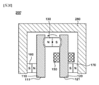
図1aから図1dは、本発明の一実施例に係る磁気力制御装置の概略的な断面図である。 1a to 1d are schematic cross-sectional views of a magnetic force control device according to an embodiment of the present invention.
本実施例に係る磁気力制御装置100は、第1ポールピース110、第2ポールピース120、回転永久磁石130、永久磁石140、及びコイル150を含む。
The magnetic
第1ポールピース110は、鉄のような強磁性体からなり、作用面111を備える。また、第2ポールピース120は、鉄のような強磁性体からなり、作用面121を備える。
The
回転永久磁石130は、S極が第1ポールピース110と近接して磁気的に連結されると共に、N極が第2ポールピース120と近接して磁気的に連結される第1配置状態(図1a及び図1bでの配置状態)と、N極が第1ポールピース110と近接して磁気的に連結されると共に、S極が第2ポールピース120と近接して磁気的に連結される第2配置状態(図1c及び図1dでの配置状態)間に転換されるように回転可能に配置される。
The rotating
具体的に、回転永久磁石130は、第1ポールピース110と第2ポールピース120との間に配置され、第1ポールピース110と第2ポールピース120間を磁気的に連結させることができる。しかし、回転永久磁石130が第1配置状態と第2配置状態にあるとき、それぞれ互いに反対方向の磁気流れが形成される。
Specifically, the rotating
回転永久磁石130は、摩擦を最小化して回転可能であるように構成されることが好ましい。また、第1配置状態及び第2配置状態時、第1ポールピース110及び第2ポールピース120との離隔距離が近ければ近いほど、さらに大きな磁気流れを形成することができるので、好ましい。
The rotating
回転永久磁石130とポールピース110、120間に「磁気的に連結」されるということは、直接には接触しないとしても回転永久磁石130の磁気力によりポールピース110、120に磁気流れが形成され得る程度に離隔されたことを含む。例えば、回転永久磁石130がポールピース110、120に接触して発生する磁気流れの強度に比して、A%以上の強度の磁気流れがポールピース110、120に形成される場合、回転永久磁石130とポールピース110、120間に磁気的に連結されたといえる。ここで、Aは80、70、60、50、40、30、20等であってよい。しかし、先に言及したように、回転永久磁石130とポールピース110、120間の離隔距離は、最小に設定することが好ましい。
The fact that they are "magnetically connected" between the rotating
一方、回転永久磁石130は、本実施例において永久磁石を特定形状に成形した構造を例示するが、これに限定されるものではなく、永久磁石とポールピースの組み合わせで構成されてもよい。様々な回転永久磁石130の構成は、図9を参照して詳細に後述する。
On the other hand, the rotary
永久磁石140は、N極が第1ポールピース110に接触し、S極が第2ポールピース120に接触するように配置される。永久磁石140は、回転永久磁石130より作用面111、121に近く位置されることが好ましい。
The
コイル150は、第1ポールピース110及び第2ポールピース120の少なくとも一つに巻かれ得る。コイル150は、磁気流れを変更させるための適切な位置に配置されればよいが、本実施例においては、回転永久磁石130と永久磁石140との間に配置されることを例示しており、効率的な磁気流れ制御においてこのような配置が好ましい。
The
以下においては、図1aから図1dをまた参照して、磁性体である対象物1をホールディングし、解除する原理について説明する。
In the following, the principle of holding and releasing the
まず、図1aを参照すると、コイル150に電流を全く印加しなければ、回転永久磁石130は、永久磁石140による第1ポールピース110及び第2ポールピース120の磁化により自動的に第1配置状態に配置される。これによって点線のように、内部循環磁気流れが形成される。これによって、作用面111、121の方向には磁気流れが形成されず、対象物が作用面111、121にホールディングされ得ない。
First, referring to FIG. 1a, if no current is applied to the
作用面111、121の方向に磁気流れを形成するためには、図1bのようにコイル150に電流を印加する。即ち、第1ポールピース110の作用面111の方向にN極が形成され、その反対側にS極が形成されるように第1ポールピース110に巻かれたコイル150を制御し、第2ポールピース120の作用面121の方向にS極が形成され、その反対側にN極が形成されるように第2ポールピース120に巻かれたコイル150を制御する。
In order to form a magnetic flow in the directions of the working
コイル150に印加される電流が十分に大きいならば、回転永久磁石130と対面する第1ポールピース110の面は、S極を帯びるようになり、回転永久磁石130と対面する第2ポールピース120の面は、N極を帯びるようになる。すると、回転永久磁石130は、各ポールで斥力を受けるようになって、回転力を受けるようになり、回転するようになる。
If the current applied to the
回転永久磁石130の図1cのように第2配置状態に配置が転換され、これによって作用面111、121がそれぞれN極とS極を帯びるようになり、対象物1をホールディングできるようになる。このとき、磁気流れは、対象物1を通過するように図1cの点線のように形成される。一旦、図1cのような磁気流れが形成されると、コイル150に印加される電流を除去しても磁気流れが維持されることで、ホールディングが維持される。
The arrangement of the rotating
ホールディングされた対象物1を解除するためには、図1dのようにコイル150に電流を印加すればよい。即ち、図1bと反対方向の電流をコイル150に印加すると、回転永久磁石130と対面する第1ポールピース110の面は、N極を帯びるようになり、回転永久磁石130と対面する第2ポールピース120の面は、S極を帯びるようになる。すると、回転永久磁石130は、各ポールで斥力を受けるようになって、回転力を受けるようになり、図1aのように第1配置状態に配置が転換される。これによって、作用面111、121から対象物1が解除され得る。
In order to release the held
一旦、第1配置状態に回転永久磁石130の配置が転換されると、コイル150に電流を印加しなくても、図1aの点線のような内部循環磁気流れが形成され、作用面111、121に対象物1がホールディングされ得ない。
Once the arrangement of the rotating
一方、図1b及び図1dに示した回転永久磁石130の回転方向は、例示的なものであるので、いかなる方向に回転されても構わない。以下においても、回転永久磁石130の回転方向は、例示に過ぎない。
On the other hand, since the rotation direction of the rotating
即ち、本実施例の磁気力制御装置100は、コイル150に印加される電流を制御することで、回転永久磁石130を回転させて第1配置状態と第2配置状態間の転換を発生させ、これによって第1ポールピース110及び第2ポールピース120の作用面111、121上の磁気力を制御する。
That is, the magnetic
図2は、他の実施例に係る磁気力制御装置の概略的な断面図である。 FIG. 2 is a schematic cross-sectional view of the magnetic force control device according to another embodiment.
図2の磁気力制御装置100'は、図1aから図1dの磁気力制御装置100に第1永久磁石160、第2永久磁石170、及びポールピース180の構成を付加したことを特徴とする。
The magnetic force control device 100'of FIG. 2 is characterized in that the configurations of the first
第1永久磁石160は、N極が第1ポールピース110に接触し、S極がポールピース180に接触するように配置される。第2永久磁石170は、S極が第2ポールピース120に接触し、N極がポールピース180に接触するように配置される。
The first
ポールピース180は、第1永久磁石160及び第2永久磁石170を磁気的に連結することで、内部に点線のような磁気流れを生成させる。ポールピース180は、磁気シールドと共に、ケースに活用され得る。
The
本実施例の磁気力制御装置100'は、磁気力制御装置100より多くの永久磁石140、160、170を保有することで、より強いホールディング力を得ることができる。
The magnetic force control device 100'of this embodiment can obtain a stronger holding force by possessing more
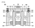
図3aから図3eは、本発明のまた他の実施例に係る磁気力制御装置の概略的な断面図である。また、図3fは、図3aから図3eを変形して構成した磁気力制御装置の断面図である。 3a to 3e are schematic cross-sectional views of the magnetic force control device according to the other embodiment of the present invention. Further, FIG. 3f is a cross-sectional view of a magnetic force control device configured by modifying FIGS. 3a to 3e.
図3aから図3eを参照すると、本実施例に係る磁気力制御装置200は、第1ポールピース110、第2ポールピース120、回転永久磁石130、コイル150、第1永久磁石160、第2永久磁石170、及び連結ポールピース280を含む。
Referring to FIGS. 3a to 3e, the magnetic
本説明において、図1aから図1dの磁気力制御装置100と同じ構成についての説明は省略し、相違点について具体的に説明する。
In this description, the description of the same configuration as that of the magnetic
第1永久磁石160は、N極が第1ポールピース110に接触し、S極が連結ポールピース280に接触するように配置される。第2永久磁石170は、S極が第2ポールピース120に接触し、N極が連結ポールピース280に接触するように配置される。
The first
ここで、回転永久磁石130、第1永久磁石160、及び第2永久磁石170は、本実施例のように一列に配置されることが磁気流れの形成において好ましくあり得る。具体的に、回転永久磁石130が第1配置状態と第2配置状態時にある時に、各ポールが一列に配置されることが磁気流れの形成において好ましくあり得る。
Here, it may be preferable in the formation of the magnetic flow that the rotating
連結ポールピース280は、鉄のような強磁性体からなり、第1永久磁石160のS極が接触し、第2永久磁石170のN極が接触する。また、連結ポールピース180は、第1ポールピース110及び第2ポールピース120とそれぞれギャップ(gap)Gを形成しながら磁気的に連結可能に配置される。
The connecting
ここで、ギャップGは、連結ポールピース280とポールピース110、120間に磁気的に連結され得る程度に設定される。即ち、連結ポールピース280とポールピース110、120間に接触して形成される磁気流れの強度に比して、B%以上の強度の磁気流れが伝達されるならば、磁気的に連結されたといえる。ここで、Bは、60、50、40、30、20等であってよい。
Here, the gap G is set to such an extent that it can be magnetically connected between the connecting
コイル150は、第1ポールピース110、第2ポールピース120、及び連結ポールピース280の少なくとも一つに巻かれ得る。コイル150は、磁気流れを変更させるための適切な位置に配置されればよいが、本実施例においては、第1ポールピース110と第2ポールピース120にそれぞれ作用面111、121に近接してコイル150を配置したことを例示している。このようにコイル150が第1ポールピース110の作用面111と第1永久磁石160との間及び第2ポールピース120の作用面121と第2永久磁石170との間に配置されると、作用面111、121での磁気力の直接的な制御が可能であり、回転永久磁石130の配置状態の転換において容易であるので、好ましい。図示しないが、さらに適正な制御のために、ギャップGと第1永久磁石160との間の第1ポールピース110にコイルがさらに巻かれ、ギャップGと第2永久磁石170との間にコイルがさらに巻かれることがさらに好ましい。
The
以下においては、図3aから図3eをまた参照して、磁性体である対象物1をホールディングし、解除する原理について説明する。
In the following, the principle of holding and releasing the
まず、図3aを参照すると、コイル150に電流を全く印加しなければ、回転永久磁石130は、第1永久磁石160及び第2永久磁石170による第1ポールピース110及び第2ポールピース120の磁化により自動的に第1配置状態に配置される。これにより点線のように、連結ポールピース180を通した内部循環磁気流れが形成される。これによって、作用面111、121の方向には磁気流れが形成されず、対象物が作用面111、121にホールディングされ得ない。
First, referring to FIG. 3a, if no current is applied to the
作用面111、121の方向に磁気流れを形成するためには、図3bのようにコイル150に電流を印加する。即ち、第1ポールピース110の作用面111の方向にN極が形成され、その反対側にS極が形成されるように第1ポールピース110に巻かれたコイル150を制御し、第2ポールピース120の作用面121の方向にS極が形成され、その反対側にN極が形成されるように第2ポールピース120に巻かれたコイル150を制御する。
In order to form a magnetic flow in the directions of the working
コイル150に印加される電流が十分に大きいならば、回転永久磁石130と対面する第1ポールピース110の面は、S極を帯びるようになり、回転永久磁石130と対面する第2ポールピース120の面は、N極を帯びるようになる。すると、回転永久磁石130は、各ポールで斥力を受けるようになって、回転力を受けるようになり、図3cのように回転するようになる。
If the current applied to the
このとき、回転する間に、ギャップGを通過する点線のような磁気流れが図3cのように形成される。もちろん、コイル150に印加された電流により作用面111、121にもN極とS極がそれぞれ形成される。
At this time, during rotation, a magnetic flow such as a dotted line passing through the gap G is formed as shown in FIG. 3c. Of course, the N pole and the S pole are also formed on the working
対象物1が作用面111、121に近接すると、ギャップGを通過していた磁気流れは弱化し、図3dのように回転永久磁石130、第1永久磁石160、及び第2永久磁石170の磁気流れは対象物1を通過することで、対象物1が作用面111、121に強固にホールディングされる。
When the
言い換えれば、回転永久磁石130の配置転換の前後に、対象物1が作用面111、121にホールディングされる。一旦、図3dのような磁気流れが形成されると、コイル150に印加される電流を除去しても構わない。しかし、コイル150に印加される電流を完全に除去せず、図3bのような方向の電流をある程度印加することが回転永久磁石130の安定的な固定のために好ましくあり得る。コイル150にどの程度の電流を印加して初めて安定性に十分であるかは、ポールピース110、120、280の厚さ、形状、及び永久磁石130、160、170の強度、対象物1の厚さ等によって決定されるだろう。
In other words, the
ホールディングされた対象物1を解除するためには、図3eのようにコイル150に電流を印加すればよい。即ち、図3bと反対方向の電流をコイル150に印加すると、回転永久磁石130と対面する第1ポールピース110の面は、N極を帯びるようになり、回転永久磁石130と対面する第2ポールピース120の面は、S極を帯びるようになる。すると、回転永久磁石130は、各ポールで斥力を受けるようになって、回転力を受けるようになり、図3aのように第1配置状態に配置が転換される。これによって、作用面111、121から対象物1が解除され得る。
In order to release the held
一旦、第1配置状態に回転永久磁石130の配置が転換されると、コイル150に電流を印加しなくても、図3aの点線のような内部循環磁気流れが形成され、作用面111、121に対象物1がホールディングされ得ない。
Once the arrangement of the rotating
一方、図3b及び図3eに示した回転永久磁石130の回転方向は、例示的なものであるので、いかなる方向に回転されても構わない。以下においても、回転永久磁石130の回転方向は、例示に過ぎない。
On the other hand, since the rotation direction of the rotating
図3fを参照すると、回転永久磁石130と第1永久磁石160/第2永久磁石170が図3aから図3eとは異なり、一直線でないように配置されてもよい。この場合、回転永久磁石130と第2永久磁石170との間の第2ポールピース120にコイル150が配置されることが好ましい。しかし、図3fのようなコイル150の配置は例示的であり、回転永久磁石130と第1永久磁石160との間の第1ポールピース110にのみコイル150が配置されてもよい。また、第1ポールピース110及び第2ポールピース120にコイル150が全て配置されてもよい。
Referring to FIG. 3f, the rotating
図3fの磁気力制御装置200'は、磁気流れの制御に有利であり、最小のコイル150を使用しても構わない。
The magnetic force control device 200'in FIG. 3f is advantageous for controlling the magnetic flow, and the
図4aから図4eは、本発明のまた他の実施例に係る磁気力制御装置の概略的な断面図である。 4a to 4e are schematic cross-sectional views of the magnetic force control device according to the other embodiment of the present invention.
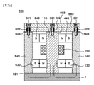
図4aから図4eを参照すると、本実施例の磁気力制御装置300は、第1ポールピース110、第2ポールピース120、回転永久磁石130、コイル150、第1永久磁石160、第2永久磁石170、連結ポールピース380、第3ポールピース385、及び第4ポールピース390を含む。
Referring to FIGS. 4a to 4e, the magnetic
本実施例において、第1ポールピース110、第2ポールピース120、回転永久磁石130、コイル150、第1永久磁石160、及び第2永久磁石170は、図3aから図3eを参照して上述した磁気力制御装置200でのそれらと同じ構成であって、同じ参照番号を付与した。同じ構成についての説明は重複であるので、省略することとし、相違点について具体的に説明する。
In this embodiment, the
本実施例の磁気力制御装置300においては、上述した磁気力制御装置200とは異なり、連結ポールピース380に第1永久磁石160及び第2永久磁石170が接触せず、第3ポールピース385及び第4ポールピース390が第1永久磁石160及び第2永久磁石170と接触する。
In the magnetic
第3ポールピース385は、鉄のような強磁性体からなり、第1永久磁石160のS極と接触する。また、第4ポールピース390は、鉄のような強磁性体からなり、第2永久磁石170のN極と接触する。
The
第3ポールピース385は、作用面386を有し得、第4ポールピース390は、作用面391を有し得る。この作用面386、391は、第1ポールピース110及び第2ポールピース120の作用面111、121と共に、対象物1をホールディングできるように形成される。
The
連結ポールピース380は、第3ポールピース385及び第4ポールピース390と磁気的に連結される第1位置(図4a、図4b、及び図4cでの位置)と、第3ポールピース385及び第4ポールピース390の少なくとも一つと磁気的に連結されない第2位置(図4d及び図4eでの位置)間に移動可能に構成される。
The connecting
連結ポールピース380が図4aのような第1位置に位置された場合であっても、第1ポールピース110及び第2ポールピース120とギャップGを形成しながら磁気的に連結可能に離隔される。
Even when the connecting
連結ポールピース380は、ボルト301により第3ポールピース385及び第4ポールピース390に移動可能であるように固定される。連結ポールピース380には、カウンターボア(counter bore)が形成され、このカウンターボアにボルト301のヘッドが係止することで移動距離が制限される。
The connecting
連結ポールピース380と第3ポールピース385/第4ポールピース390との間には、それぞればねのような弾性部材302が介在されることが好ましい。このような弾性部材302は、連結ポールピース380が第3ポールピース385及び第4ポールピース390と離れる方向に連結ポールピース380に力を加えるようになる。
It is preferable that an
また、連結ポールピース380と第3ポールピース385との間、または連結ポールピース380と第4ポールピース390との間には、弾性を有する衝撃緩和部材303が介在されることが、連結ポールピース380の第2位置から第1位置への移動時に発生する衝撃を緩和させることができるので、好ましい。衝撃緩和部材303は、板形状のゴム、重合体等であってよく、磁気流れに影響を及ぼさない非磁性材質からなることが好ましい。
Further, the connecting pole piece may have an elastic
一方、コイル150は、より適正な磁気流れの制御のために、連結ポールピース380にも追加して巻かれることが好ましい。
On the other hand, it is preferable that the
以下においては、図4aから図4eをまた参照して、磁性体である対象物1をホールディングし、解除する原理について説明する。
In the following, the principle of holding and releasing the
まず、図4aを参照すると、コイル150に電流を全く印加しなければ、回転永久磁石130は、第1永久磁石160及び第2永久磁石170による第1ポールピース110及び第2ポールピース120の磁化により自動的に第1配置状態に配置される。これと併せて、連結ポールピース380は第1位置に位置されることで、点線のように、連結ポールピース380を通した内部循環磁気流れが形成される。これによって、作用面111、121、386、391の方向には磁気流れが形成されず、対象物が作用面111、121、386、391にホールディングされ得ない。
First, referring to FIG. 4a, if no current is applied to the
作用面111、121、386、391の方向に磁気流れを形成するためには、図4bのようにコイル150に電流を印加する。即ち、第1ポールピース110の作用面111の方向にN極が形成され、その反対側にS極が形成されるように第1ポールピース110に巻かれたコイル150を制御し、第2ポールピース120の作用面121の方向にS極が形成され、その反対側にN極が形成されるように第2ポールピース120に巻かれたコイル150を制御し、連結ポールピース380の右側にN極が形成されるようにコイル150をそれぞれ制御する。
In order to form a magnetic flow in the directions of the working
コイル150に印加される電流が十分に大きいならば、回転永久磁石130と対面する第1ポールピース110の面は、S極を帯びるようになり、回転永久磁石130と対面する第2ポールピース120の面は、N極を帯びるようになる。すると、回転永久磁石130は、各ポールで斥力を受けるようになって、回転力を受けるようになり、図4cのように回転するようになる。
If the current applied to the
このとき、回転する間に、ギャップGを通過する点線のような磁気流れが図4cのように形成される。もちろん、コイル150に印加された電流により作用面111、121にもN極とS極がそれぞれ形成される。
At this time, during rotation, a magnetic flow such as a dotted line passing through the gap G is formed as shown in FIG. 4c. Of course, the N pole and the S pole are also formed on the working
対象物1が作用面111、121に近接すると、ギャップGを通過していた磁気流れは弱化し、図4dのように回転永久磁石130、第1永久磁石160、及び第2永久磁石170の磁気流れは対象物1を通過することで、対象物1が作用面111、121に強固にホールディングされる。
When the
また、これと共に、第3ポールピース385と対面する連結ポールピース380の面がS極で形成され、第4ポールピース390と対面する連結ポールピース380の面がN極で形成されることで、連結ポールピース380は、弾性部材302の弾性力により第2位置に移動される。
At the same time, the surface of the connecting
これによって、図4dのように、回転永久磁石130は、第2配置状態に配置され、連結ポールピース380は、第2位置に位置される。回転永久磁石130及び連結ポールピース380の配置の前後に、対象物1が作用面111、121、386、391にホールディングされる。ホールディングと共に、図4dのように対象物1を通過する点線で示された磁気流れが形成される。一旦、図4dのような磁気流れが形成されると、コイル150に印加される電流を除去しても構わない。しかし、コイル150に印加される電流を完全に除去せず、図4bのような方向の電流をある程度印加することが回転永久磁石130の安定的な固定のために好ましくあり得る。コイル150にどの程度の電流を印加して初めて安定性に十分であるかは、ポールピース110、120、380、385、390の厚さ、形状、及び永久磁石130、160、170の強度、対象物1の厚さ等によって決定されるだろう。
As a result, as shown in FIG. 4d, the rotating
ホールディングされた対象物1を解除するためには、図4eのようにコイル150に電流を印加すればよい。即ち、図4bと反対方向の電流をコイル150に印加すると、回転永久磁石130と対面する第1ポールピース110の面は、N極を帯びるようになり、回転永久磁石130と対面する第2ポールピース120の面は、S極を帯びるようになる。すると、回転永久磁石130は、各ポールで斥力を受けるようになって、回転力を受けるようになり、図4aのように第1配置状態に配置が転換される。また、これと共に、第3ポールピース385と対面する連結ポールピース380の面がN極で形成され、第4ポールピース390と対面する連結ポールピース380の面がS極で形成されることで、連結ポールピース380は、弾性部材302の弾性力に打勝って第1位置に移動される。これによって、図4aのような内部循環磁気流れが形成され、作用面111、121、386、391から対象物1が解除され得る。
In order to release the held
一旦、第1配置状態に回転永久磁石130の配置が転換され、第1位置に連結ポールピース380が移動されると、コイル150に電流を印加しなくても、図4aの点線のような内部循環磁気流れが形成され、作用面111、121に対象物1がホールディングされ得ない。
Once the arrangement of the rotating
図5aから図5eは、本発明のまた他の実施例に係る磁気力制御装置の概略的な断面図である。また、図5fは、図5aから図5eの磁気力制御装置のまた他の変形実施例の概略的な断面図である。 5a to 5e are schematic cross-sectional views of the magnetic force control device according to the other embodiment of the present invention. Further, FIG. 5f is a schematic cross-sectional view of another modified embodiment of the magnetic force control device of FIGS. 5a to 5e.
図5aから図5eを参照すると、本実施例の磁気力制御装置400は、第1ポールピース110、第2ポールピース120、回転永久磁石130、コイル150、永久磁石440、及び連結ポールピース480を含む。
Referring to FIGS. 5a to 5e, the magnetic
本実施例において、第1ポールピース110、第2ポールピース120、回転永久磁石130、及びコイル150は、図1aから図1dを参照して上述した磁気力制御装置100でのそれらと同じ構成であって、同じ参照番号を付与した。同じ構成についての説明は重複であるので、省略することとし、相違点について具体的に説明する。
In this embodiment, the
本実施例において、永久磁石440は、N極が第1ポールピース110に接触し、S極が第2ポールピース120に接触するように配置される。永久磁石440は、図1aから図1dでの永久磁石140と他の構成は同じであるが、配置で差があって他の参照番号を付与しただけであり、実質的には同じ構成である。
In this embodiment, the
回転永久磁石130は、永久磁石440より作用面111、121に近接して位置され得る。これによって、作用面111、121上の磁気力の制御がより容易である。しかし、永久磁石440が作用面111、121に近接して位置されてもよい。
The rotating
第1ポールピース110と第2ポールピース120は、連結ポールピース480とギャップGを形成しながら磁気的に連結可能に離隔される。ギャップGの構成については、上述したとおりであるので、重複説明は省略する。
The
コイル150は、回転永久磁石130と永久磁石340との間の第1ポールピース110及び第2ポールピース120にそれぞれ巻かれ、第1ポールピース110の作用面111と回転永久磁石130との間の第1ポールピース110に巻かれ、第2ポールピース120の作用面121と回転永久磁石130との間の第2ポールピース120に巻かれるように配置されることが、回転永久磁石130の配置転換に容易であるので、好ましい。
The
以下においては、図5aから図5eをまた参照して、磁性体である対象物1をホールディングし、解除する原理について説明する。
In the following, the principle of holding and releasing the
まず、図5aを参照すると、コイル150に電流を全く印加しなければ、回転永久磁石130は、永久磁石440による第1ポールピース110及び第2ポールピース120の磁化により自動的に第1配置状態に配置される。これによって点線のように、永久磁石440、第1ポールピース110、回転永久磁石130、及び第2ポールピース120を通過する内部循環磁気流れが形成される。このとき、ギャップGにより、永久磁石440からの磁気流れは、連結ポールピース480に渡ることが難しい。これによって、作用面111、121の方向には磁気流れが形成されず、対象物が作用面111、121にホールディングされ得ない。
First, referring to FIG. 5a, if no current is applied to the
作用面111、121の方向に磁気流れを形成するためには、図5bのようにコイル150に電流を印加する。即ち、回転永久磁石130のS極と近接した部分の第1ポールピース110にS極が形成され、N極と近接した部分の第2ポールピース120にN極が形成されるように、コイル150を制御する。
In order to form a magnetic flow in the directions of the working
コイル150に印加される電流が十分に大きいならば、回転永久磁石130と対面する第1ポールピース110の面は、S極を帯びるようになり、回転永久磁石130と対面する第2ポールピース120の面は、N極を帯びるようになる。すると、回転永久磁石130は、各ポールで斥力を受けるようになって、回転力を受けるようになり、図5cのように回転するようになる。
If the current applied to the
このとき、回転する間に、ギャップGを通過する点線のような磁気流れが図5cのように形成される。もちろん、コイル150に印加された電流により作用面111、121にもN極とS極がそれぞれ形成される。
At this time, during rotation, a magnetic flow such as a dotted line passing through the gap G is formed as shown in FIG. 5c. Of course, the N pole and the S pole are also formed on the working
対象物1が作用面111、121に近接すると、ギャップGを通過していた磁気流れは弱化し、図5dのように回転永久磁石130及び永久磁石440からの磁気流れは対象物1を通過することで、対象物1が作用面111、121に強固にホールディングされる。
When the
回転永久磁石130の配置転換の前後に、対象物1が作用面111、121にホールディングされる。ホールディングと共に、図5dのように対象物1を通過する点線で示された磁気流れが形成される。一旦、図5dのような磁気流れが形成されると、コイル150に印加される電流を除去しても構わない。しかし、回転永久磁石130と作用面111、121との間に位置するコイル150に印加される電流を完全に除去せず、図5bのような方向の電流をある程度印加することが回転永久磁石130の安定的な固定のために好ましくあり得る。コイル150にどの程度の電流を印加して初めて安定性に十分であるかは、ポールピース110、120、480の厚さ、形状、及び永久磁石130、440の強度、対象物1の厚さ等によって決定されるだろう。
Before and after the rearrangement of the rotating
ホールディングされた対象物1を解除するためには、図5eのようにコイル150に電流を印加すればよい。即ち、図5bと反対方向の電流をコイル150に印加すると、回転永久磁石130と対面する第1ポールピース110の面は、N極を帯びるようになり、回転永久磁石130と対面する第2ポールピース120の面は、S極を帯びるようになる。すると、回転永久磁石130は、各ポールで斥力を受けるようになって、回転力を受けるようになり、図5aのように第1配置状態に配置が転換される。これによって、作用面111、121から対象物1が解除され得る。
In order to release the held
一旦、第1配置状態に回転永久磁石130の配置が転換されると、コイル150に電流を印加しなくても、図3aの点線のような内部循環磁気流れが形成され、作用面111、121に対象物1がホールディングされ得ない。
Once the arrangement of the rotating
図5fを参照すると、変形例である磁気力制御装置400'は、上述した磁気力制御装置400の構成に、第3ポールピース485、第2永久磁石450、及び第2回転永久磁石490をさらに含んで構成される。
Referring to FIG. 5f, the magnetic force control device 400', which is a modified example, further includes a
第3ポールピース485は、作用面486を備え、鉄のような強磁性体からなる。
The
第2永久磁石450は、第1ポールピース110にN極が接触し、第3ポールピース485にS極が接触するように配置される。
The second
第2回転永久磁石490は、N極が第3ポールピース485と磁気的に連結されると共にS極が第1ポールピース110と磁気的に連結される第1配置状態と、N極が第1ポールピース110と磁気的に連結されると共にS極が第3ポールピース485と磁気的に連結される第2配置状態をなすことができるように回転可能に構成される。
The second rotating
連結ポールピース480'は、第1ポールピース110、第2ポールピース120、及び第3ポールピース485とギャップGを形成しながら磁気的に連結可能に離隔される。
The connecting pole piece 480'is magnetically coupled and separated from the
このように、図5aから図5eの磁気力制御装置400は、横に拡張され得る。具体的な作動原理は、上述した磁気力制御装置400の作動原理と同一であるので、詳細な説明は省略する。
In this way, the magnetic
図6aから図6dは、本発明のまた他の実施例に係る磁気力制御装置の概略的な断面図である。 6a to 6d are schematic cross-sectional views of the magnetic force control device according to the other embodiment of the present invention.
図6aから図6dを参照すると、本実施例の磁気力制御装置500は、第1ポールピース110、第2ポールピース120、回転永久磁石130、コイル150、永久磁石440、及び連結ポールピース580を含む。
Referring to FIGS. 6a to 6d, the magnetic
本実施例において、第1ポールピース110、第2ポールピース120、回転永久磁石130、永久磁石440、及びコイル150は、上述した磁気力制御装置100、200、300、400でのそれらと同じ構成であって、同じ参照番号を付与した。同じ構成についての説明は重複であるので、省略することとし、相違点について具体的に説明する。
In this embodiment, the
連結ポールピース580は、第1ポールピース110及び第2ポールピース120の少なくとも一つと磁気的に連結されない第1位置(図6a及び図6bでの位置)、及び、第1ポールピース110及び第2ポールピースと磁気的に連結される第2位置(図6c及び図6dでの位置)間に移動可能に構成される。
The connecting
コイル150は、第1ポールピース110、第2ポールピース120、及び連結ポールピース580の少なくとも一つに巻かれ得るが、本実施例のように、回転永久磁石130と永久磁石440との間の第1ポールピース110及び第2ポールピース120にそれぞれ巻かれることが好ましい。
The
連結ポールピース580は、ボルト501により第1ポールピース110及び第2ポールピース120に移動可能であるように固定される。連結ポールピース580には、カウンターボア(counter bore)が形成され、このカウンターボアにボルト501のヘッドが係止することで移動距離が制限される。
The connecting
連結ポールピース580と第1ポールピース110/第2ポールピース120との間には、それぞればねのような弾性部材502が介在されることが好ましい。このような弾性部材502は、連結ポールピース580が第1ポールピース110及び第2ポールピース120と離れる方向に連結ポールピース580に力を加えるようになる。
It is preferable that an
また、連結ポールピース580と第1ポールピース110との間、または連結ポールピース580と第2ポールピース120との間には、弾性を有する衝撃緩和部材503が介在されることが、連結ポールピース580の第1位置から第2位置への移動時に発生する衝撃を緩和させることができるので、好ましい。衝撃緩和部材503は、板形状のゴム、重合体等であってよく、磁気流れに影響を及ぼさない非磁性材質からなることが好ましい。
Further, the connecting pole piece may have an elastic
以下においては、図6aから図6dをまた参照して、磁性体である対象物1をホールディングし、解除する原理について説明する。
In the following, the principle of holding and releasing the
まず、図6aを参照すると、コイル150に電流を全く印加しなければ、回転永久磁石130は、第1永久磁石140及び第2永久磁石150による第1ポールピース110及び第2ポールピース120の磁化により自動的に第1配置状態に配置される。これと併せて、連結ポールピース580は第1位置に位置されることで、点線のように、内部循環磁気流れが形成される。これによって、作用面111、121の方向には磁気流れが形成されず、対象物が作用面111、121にホールディングされ得ない。
First, referring to FIG. 6a, if no current is applied to the
作用面111、121の方向に磁気流れを形成するためには、図6bのようにコイル150に電流を印加する。即ち、永久磁石440の方向にN極が形成され、回転永久磁石130の方向にS極が形成されるように第1ポールピース110に巻かれたコイル150を制御し、永久磁石440の方向にS極が形成され、回転永久磁石130の方向にN極が形成されるように第2ポールピース120に巻かれたコイル150を制御する。
In order to form a magnetic flow in the directions of the working
コイル150に印加される電流が十分に大きいならば、回転永久磁石130と対面する第1ポールピース110の面は、S極を帯びるようになり、回転永久磁石130と対面する第2ポールピース120の面は、N極を帯びるようになる。すると、回転永久磁石130は、各ポールで斥力を受けるようになって、回転力を受けるようになり、図6cのように回転して配置状態が転換される。
If the current applied to the
また、これと共に、第1ポールピース110及び第2ポールピース120は連結ポールピース580を引き寄せ、連結ポールピース580は弾性部材502の弾性力に打勝って、第2位置に移動される。図4cのように連結ポールピース580が移動されると、永久磁石440からの磁気流れは、連結ポールピース580を通して形成される。
At the same time, the
これによって、回転永久磁石130からの磁気流れで対象物1がホールディングされるようになる。
As a result, the
ホールディングされた対象物1を解除するためには、図6dのようにコイル150に電流を印加すればよい。即ち、図6bと反対方向の電流をコイル150に印加すると、回転永久磁石130と対面する第1ポールピース110の面は、N極を帯びるようになり、回転永久磁石130と対面する第2ポールピース120の面は、S極を帯びるようになる。すると、回転永久磁石130は、各ポールで斥力を受けるようになって、回転力を受けるようになり、図6aのように第1配置状態に配置が転換される。また、これと共に、第1ポールピース110と第2ポールピース120が連結ポールピース580を引き寄せる力が弱くなって、弾性部材502の弾性により連結ポールピース580はまた第1位置に復帰する。これによって、図6aのような内部循環磁気流れが形成され、作用面111、121から対象物1が解除され得る。
In order to release the held
図7aから図7dは、本発明のまた他の実施例に係る磁気力制御装置の概略的な断面図である。 7a to 7d are schematic cross-sectional views of the magnetic force control device according to the other embodiment of the present invention.
図7aから図7dを参照すると、本実施例の磁気力制御装置600は、第1ポールピース110、第2ポールピース120、第1回転永久磁石130、第1永久磁石440、連結ポールピース680、コイル150、第3ポールピース620、第2回転永久磁石630、及び第2永久磁石640を含む。
Referring to FIGS. 7a to 7d, the magnetic
本実施例の磁気力制御装置600は、上述した磁気力制御装置500の構成において、第3ポールピース620、第2回転永久磁石630、及び第2永久磁石640をさらに含みながら、連結ポールピース680を変形した構造を有する。同じ機能を果たす構成に対しては、図6aから図6dで表示した識別番号と同じ識別番号を付与した。
The magnetic
本実施例の磁気力制御装置600は、上述した磁気力制御装置500を拡張したものであって、第3ポールピース620をさらに備える。第3ポールピース620は、作用面621を備え、鉄のような強磁性体からなる。
The magnetic
第2回転永久磁石630は、N極が第3ポールピース620と磁気的に連結されると共にS極が第1ポールピース110と磁気的に連結される第1配置状態(図7a及び図7bでの配置状態)と、N極が第1ポールピース110と磁気的に連結されると共にS極が第3ポールピース620と磁気的に連結される第2配置状態(図7c及び図7dでの配置状態)をなすことができるように回転可能に構成される。
The second rotating
第2永久磁石640は、第1ポールピース110にN極が接触し、第3ポールピース620にS極が接触するように配置される。第2永久磁石640は、第1永久磁石440と一列に配置されることが好ましい。
The second
連結ポールピース680は、第1位置と第2位置間に移動が可能に構成される。第1位置とは、第1ポールピース110、第2ポールピース120、及び第3ポールピース620のうち隣接するポールピース同士は磁気的に連結させない連結ポールピース680の位置(図7a及び図7bでの位置)であり、第2位置とは、第1ポールピース110、第2ポールピース120、及び第3ポールピース620に全て磁気的に連結される連結ポールピース680の位置(図7c及び図7dでの位置)をいう。
The connecting
本実施例の磁気力制御装置600の作動原理は、図6aから図6dの磁気力制御装置500と同一であるので、詳細な説明は省略する。
Since the operating principle of the magnetic
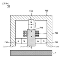
図8aから図8dは、本発明のまた他の実施例に係る磁気力制御装置の概略的な断面図である。 8a to 8d are schematic cross-sectional views of the magnetic force control device according to the other embodiment of the present invention.
図8aから図8dを参照すると、本実施例の磁気力制御装置700は、中心ポールピース710、周辺ポールピース720、永久磁石730、回転永久磁石740、及びコイル750を含む。
Referring to FIGS. 8a to 8d, the magnetic
中心ポールピース710は、作用面711を備え、鉄のような強磁性体からなる。
The
周辺ポールピース720は、中心ポールピース710の少なくとも一部を囲むように配置され、作用面721を備え、鉄のような強磁性体からなる。
The
永久磁石730は、中心ポールピース710にN極及びS極のいずれか一つが接触し、周辺ポールピース720に他の一つが接触するように配置される。本実施例においては、中心ポールピース710にN極が接触したことを例示する。
The
永久磁石730は、少なくとも二つが備えられる場合、中心ポールピース710を中心に置いて対称をなすように配置されることが好ましい。
When at least two
回転永久磁石740は、S極が中心ポールピース710と磁気的に連結された状態で離隔されると共にN極が周辺ポールピース720と磁気的に連結された状態で離隔される第1配置状態(図8a及び図8bでの配置状態)と、S極が周辺ポールピース720と磁気的に連結された状態で離隔されると共にN極が中心ポールピース710と磁気的に連結された状態で離隔される第2配置状態(図8c及び図8dでの配置状態)をなすことができるように回転可能に構成される。
The rotating
回転永久磁石740は、第1配置状態または第2配置状態時に、N極またはS極が中心ポールピース710の作用面711に向かうように配置されることが好ましい。即ち、中心ポールピース710が長く形成される場合、回転永久磁石740が長手方向に配列され得るように構成されることが好ましい。このような配置により中心ポールピース710の作用面711への磁気力制御がより容易である。
It is preferable that the rotating
コイル750は、中心ポールピース710及び周辺ポールピース720の少なくとも一つに巻かれるように配置され、本実施例のように中心ポールピース710にのみ配置されてもよい。
The
以下においては、図8aから図8dをまた参照して、磁性体である対象物1をホールディングし、解除する原理について説明する。
In the following, the principle of holding and releasing the
まず、図8aを参照すると、コイル750に電流を全く加えなければ、回転永久磁石740は、第1配置状態をなし、点線のような内部循環磁気流れが形成され、これによって作用面711、721に対象物がホールディングされ得ない。
First, referring to FIG. 8a, if no current is applied to the
ホールディングのために、図8bのようにコイル750に電流を印加すると、回転永久磁石730の方向にS極が形成される。これと共に、対象物1を作用面711、721に近接させると、図8cのように回転永久磁石730が第2配置状態に回転しながら、対象物1が作用面711、721にホールディングされる。
When a current is applied to the
ホールディングされると、図8cのように対象物1を通過する磁気流れが形成されながら、対象物が作用面711、721に強固にホールディングされる。
When held, the object is firmly held on the working
以後、解除のためには、図8dのように図8bとは反対方向にコイル750に電流を印加すると、回転永久磁石740の方向にN極が形成されるので、回転永久磁石740が回転して、図8aのような第1配置状態に変更される。これによって、図8aのような内部循環磁気流れが形成され、対象物1は解除される。
After that, when a current is applied to the
図9は、回転永久磁石の様々な実施形態を示した断面図である。 FIG. 9 is a cross-sectional view showing various embodiments of a rotating permanent magnet.
図9の(a)を参照すると、回転永久磁石130'は、断面が円形である円筒形状で構成され得る。この場合、回転永久磁石130'は、永久磁石自体からなる。 Referring to (a) of FIG. 9, the rotating permanent magnet 130'may be configured in a cylindrical shape having a circular cross section. In this case, the rotating permanent magnet 130'consists of the permanent magnet itself.
図9の(b)を参照すると、回転永久磁石130''は、断面がほぼ楕円形で構成され得る。この場合、回転永久磁石130''は、永久磁石自体からなる。参考までに、本形態は、図1aから図6dにおいて例示したとおりである。また、具体的な説明は、図10を参照して後述する。 Referring to (b) of FIG. 9, the rotating permanent magnet 130'' may be configured with a substantially elliptical cross section. In this case, the rotating permanent magnet 130'' is composed of the permanent magnet itself. For reference, this embodiment is as illustrated in FIGS. 1a to 6d. Further, a specific description will be described later with reference to FIG.
図9の(c)を参照すると、回転永久磁石130'''は、永久磁石131と、Nポールピース132と、Sポールピース133とを含んで構成され得る。Nポールピース132及びSポールピース133は、鉄のような強磁性体からなり得る。
Referring to (c) of FIG. 9, the rotating permanent magnet 130'''can be configured to include a
図9の(d)を参照すると、回転永久磁石130''''は、回転永久磁石130'''に非磁性体材質の保護体134をさらに備えることができる。この場合、回転永久磁石130''''は、全般的に円筒形状を有する。
Referring to (d) of FIG. 9, the rotating permanent magnet 130'''' may further include a
図9の(e)を参照すると、回転永久磁石130'''''は、二つの永久磁石131a、131bと、Nポールピース132と、Sポールピース133と、中間ポールピース135とを含んで構成され得る。Nポールピース132、Sポールピース133、及び中間ポールピース135は、鉄のような強磁性体からなり得る。
Referring to (e) of FIG. 9, the rotating permanent magnets 130''''' include two
このように、回転永久磁石130、130'、130''、130'''、130''''、130'''''の構成は、永久磁石自体からなってもよく、永久磁石とポールピースの組み合わせ、または非磁性体材質の組み合わせからなり得る。この他にも様々な方式で回転永久磁石が構成されてもよい。
As described above, the configuration of the rotating
一方、上で説明した回転永久磁石130は、第1配置状態または第2配置状態である場合、機械的に固定されるように構成され得る。即ち、コイルにより第1配置状態及び第2配置状態に変更された以後、配置状態の維持のために固定され得る。このような固定は、配置状態間の変更時のみ解除されるように構成され得る。このような構成により、意図しない回転永久磁石130の回転を防止することで、ホールディングまたは解除状態の安定的な維持がより可能となる。
On the other hand, the rotating
図10は、回転永久磁石の一実施形態及び磁気力制御装置に配置された状態を示す。 FIG. 10 shows an embodiment of a rotating permanent magnet and a state in which it is arranged in a magnetic force control device.
図10の(a)を参照すると、回転永久磁石130''は、回転中心Oから同じ距離だけ外縁が形成された円形部130aと、回転中心Oからの距離が円形部130aより小さく外縁が形成された非円形部130bとからなり得る。この非円形部130bにより回転永久磁石130''のN極とS極が分割される。
Referring to (a) of FIG. 10, the rotary permanent magnet 130'' has a
非円形部130bは、図10において例示したように、一字に形成され得るが、これは例示に過ぎず、曲線の形態で形成されてもよい。
The
回転永久磁石130''が第1配置状態または第2配置状態にある場合に、第1ポールピース110及び第2ポールピース120は、円形部130aの少なくとも一部とは対面し、非円形部130bとは対面しないように構成されることが好ましい。さらに好ましくは、図10の(b)のように、回転永久磁石130''が第1配置状態または第2配置状態にある場合に、第1ポールピース110及び第2ポールピース120は、円形部130aの全部と対面するように構成される。
When the rotating permanent magnet 130'' is in the first arrangement state or the second arrangement state, the
非円形部130bが備えられると、図1cの第2配置状態と図1aの第1配置状態間の回転永久磁石130の転換を難しくさせる。言い換えれば、ホールディング状態あるいは解除状態の維持をより安定的に具現できる。
The provision of the
非円形部130bの幅Aが大きければ大きいほど、配置状態の維持性能は向上するが、配置状態の転換時にコイル150に印加される電流が増加する。これに対して、非円形部130bの幅Aが小さければ小さいほど、配置状態の維持性能は低下するが、配置状態の転換時にコイル150に印加される電流は小さくなる。従って、配置状態の転換時に必要な電流値及び耐えるべき外部衝撃値を考慮して適宜A値を選定する必要がある。
The larger the width A of the
一方、回転永久磁石130は、自由に回転可能に構成されるので、軸受けを活用できる。しかし、軸受けは、磁性体からなって回転を難しくさせ、比較的に高価である。従って、軸受けの代わりにピーク(peek)、PVC、またはセラミック材質等からなるブッシング構造を適用することが好ましい。このような場合、回転構造自体が磁性を帯びず、磁石間押し摩擦が減少し、回転永久磁石130の回転が有利であり、安価で回転構造を具現できる長所がある。
On the other hand, since the rotating
図11は、図1aから図1dの磁気力制御装置の変形例である。 11 is a modification of the magnetic force control device of FIGS. 1a to 1d.
図11を参照すると、本実施例の磁気力制御装置100''は、さらなる作用面を有するという点以外に、図1aから図1dの磁気力制御装置100の構成と同じ構成を有する。
Referring to FIG. 11, the magnetic
本実施例の磁気力制御装置100''は、永久磁石140側に形成される作用面111、121以外に、回転永久磁石130側にさらなる作用面112、122を有する。具体的に、第1ポールピース110は、2個の作用面111、112を有し、第2ポールピース120は、2個の作用面121、122を有する。
The magnetic
図11の(a)は、どの作用面111、112、121、122にも磁気力が作用しなく制御された状態を例示するが、図1aの状態と対応する。また、図11の(b)は、作用面111、121には対象物1がホールディングされ、作用面112、122には対象物1'がホールディングされた状態を例示するが、図1cの状態と対応する。図1cの状態との相違点は、回転永久磁石130からの磁気流れが対象物1'に向かって、対象物1'もホールディングされるという点である。
FIG. 11A exemplifies a state in which the magnetic force does not act on any of the working
図11の(a)と(b)間の回転永久磁石130の配置変更は、図1bと図1dのようなコイル150への電流印加により行われ得、詳細な説明は、上述したとおりであるので省略する。
The arrangement of the rotating
このようなさらなる作用面112、122によりさらなる対象物1'に対する磁気力の作用(例えば、ホールディング及び解除)が可能である。このように、磁気力を作用させようとする対象物の形状、個数等により自由に作用面の配置、形状、個数等を変形できる。 Such additional action surfaces 112, 122 allow further action of magnetic force on the object 1'(eg, holding and releasing). In this way, the arrangement, shape, number, etc. of the working surface can be freely deformed depending on the shape, number, etc. of the object on which the magnetic force is applied.
図12は、図11の磁気力制御装置の変形例である。具体的に、図12の(a)は、回転永久磁石130が第1配置状態である場合の概略的な正面図及び側面図を示し、図12の(b)は、回転永久磁石130が第2配置状態である場合の概略的な正面図、側面図、及び下面図を示す。参考までに、正面図でのみコイル150を断面で示した。
FIG. 12 is a modified example of the magnetic force control device of FIG. Specifically, FIG. 12A shows a schematic front view and a side view when the rotating
図12の磁気力制御装置100'''は、図11の磁気力制御装置100''とは異なり、作用面111'、112'、121'、122'が向かう方向は、回転永久磁石130の回転軸に沿う方向と平行な方向に向かうように配置される。即ち、作用面111'、112'、121'、122'にホールディングされる対象物1と平行な平面上で回転永久磁石130が回転するように磁気力制御装置100'''が構成される。
The magnetic force control device 100'''' in FIG. 12 is different from the magnetic force control device 100'' in FIG. It is arranged so as to go in a direction parallel to the direction along the axis of rotation. That is, the magnetic force control device 100'''is configured so that the rotating
図12の(a)を参照すると、回転永久磁石130は、第1配置を形成し、この時には、内部を循環する磁気流れにより、作用面111'、112'、121'、122'は、外部の磁性体に磁気的な影響をほとんどまたは全く及ぼすことができない。
Referring to (a) of FIG. 12, the rotating
これに対して、図12の(b)のように、回転永久磁石130が第2配置を形成すると、作用面111'、112'はN極に磁化し、作用面121'、122'はS極に磁化して磁性体である対象物1に磁気的な影響を及ぼし得る。これによって、磁気力制御装置100'''は、対象物1をホールディングできる。
On the other hand, as shown in FIG. 12B, when the rotating
図12の(a)と(b)間の回転永久磁石130の配置変更は、図1bと図1dのようなコイル150への電流印加により行われ得、詳細な説明は、上述したとおりであるので省略する。
The arrangement of the rotating
本実施例の磁気力制御装置100'''は、対象物1と平行な平面上で回転永久磁石130が回転するように構成され、高さの低いコンパクトな構成の具現が可能な長所を有する。
The magnetic force control device 100'' of the present embodiment has an advantage that the rotating
以上、添付の図面を参照して本発明の実施例を説明したが、本発明の属する技術の分野における通常の知識を有する者は、本発明のその技術的思想や必須特徴を変更することなく他の具体的な形態で実施され得るということが理解できるだろう。それゆえ、以上において記述した実施例は、全ての面で例示的なものであり、限定的ではないものと理解すべきである。 Although the embodiments of the present invention have been described above with reference to the accompanying drawings, a person having ordinary knowledge in the field of the art to which the present invention belongs does not change the technical idea or essential features of the present invention. It will be understood that it can be implemented in other concrete forms. Therefore, it should be understood that the examples described above are exemplary in all respects and are not limiting.
Claims (31)
一端側に作用面を備え、強磁性体からなり、前記永久磁石のN極と接触する第1ポールピースと、
前記第1ポールピースと略平行に配置される第2ポールピースであって、前記第1ポールピースの前記一端と同じ側の一端側に作用面を備え、強磁性体からなり、前記永久磁石または前記永久磁石とは異なる永久磁石のS極と接触する第2ポールピースと、
N極が前記第2ポールピースと磁気的に連結されると共にS極が前記第1ポールピースと磁気的に連結される第1配置状態と、N極が前記第1ポールピースと磁気的に連結されると共にS極が前記第2ポールピースと磁気的に連結される第2配置状態をなすことができるように回転可能に構成される回転永久磁石と、
前記第1ポールピース及び前記第2ポールピースの少なくとも一つに巻かれるコイルと、を含み、
前記第1配置状態において、前記永久磁石の前記N極から、前記第1ポールピース、前記回転永久磁石の前記S極、前記回転永久磁石のN極、前記第2ポールピース、前記永久磁石の前記S極または前記異なる永久磁石の前記S極を経て、前記永久磁石の前記N極へと至る磁気流れが形成され、これにより、前記第1ポールピースの前記作用面の方向及び前記第2ポールピースの前記作用面の方向に、対象物をホールディングするための磁気流れは形成されず、
前記コイルに電流を印加することで、前記回転永久磁石の前記S極に対面する前記第1ポールピースの面および前記回転永久磁石の前記N極に対面する前記第2ポールピースの面の少なくとも1つに、前記回転永久磁石の前記S極または前記N極に対する斥力を形成し、これにより前記回転永久磁石を回転させて前記第1配置状態から前記第2配置状態への転換を発生させ、
前記第2配置状態において、前記回転永久磁石の前記N極および前記永久磁石の前記N極から、前記第1ポールピースの前記作用面および前記第2ポールピースの前記作用面を経て、前記回転永久磁石の前記S極及び前記永久磁石の前記S極または前記異なる永久磁石の前記S極へと至る磁気流れが形成され、これによって前記第1ポールピースの前記作用面の方向及び前記第2ポールピースの前記作用面の方向に、対象物をホールディングするための磁気流れを形成し、
前記コイルに前記電流を逆方向に印加することで、前記回転永久磁石の前記N極に対面する前記第1ポールピースの前記面および前記回転永久磁石の前記N極に対面する前記第2ポールピースの前記面の少なくとも1つに、前記回転永久磁石の前記N極または前記S極に対する斥力を形成し、これにより前記回転永久磁石を更に回転させて前記第2配置状態から前記第1配置状態への転換を発生させ、これによってホールディングされた前記対象物を解除可能とする、磁気力制御装置。 With permanent magnets
A first pole piece having a working surface on one end side, made of a ferromagnet, and in contact with the north pole of the permanent magnet,
A second pole piece that is arranged substantially parallel to the first pole piece, has a working surface on one end side on the same side as the one end of the first pole piece, is made of a ferromagnet, and is a permanent magnet or a permanent magnet. A second pole piece that comes into contact with the S pole of a permanent magnet different from the permanent magnet,
The N pole is magnetically connected to the second pole piece and the S pole is magnetically connected to the first pole piece in the first arrangement state, and the N pole is magnetically connected to the first pole piece. A rotating permanent magnet that is rotatably configured so that the S pole can form a second arrangement state in which the S pole is magnetically connected to the second pole piece.
Includes a coil wound around at least one of the first pole piece and the second pole piece.
In the first arrangement state, from the N pole of the permanent magnet, the first pole piece, the S pole of the rotating permanent magnet, the N pole of the rotating permanent magnet, the second pole piece, and the permanent magnet. A magnetic flow is formed through the S pole or the S pole of the different permanent magnet to the N pole of the permanent magnet, whereby the direction of the working surface of the first pole piece and the second pole piece. No magnetic flow for holding the object is formed in the direction of the working surface of the above.
By applying an electric current to the coil, at least the surface of the first pole piece facing the S pole of the rotating permanent magnet and the surface of the second pole piece facing the N pole of the rotating permanent magnet. First, it forms a repulsive force on the S pole or the N pole of the rotating permanent magnet, thereby rotating the rotating permanent magnet to generate a conversion from the first arrangement state to the second arrangement state.
In the second arrangement state, the rotation permanent from the N pole of the rotary permanent magnet and the N pole of the permanent magnet through the working surface of the first pole piece and the working surface of the second pole piece. A magnetic flow is formed to the S pole of the magnet and the S pole of the permanent magnet or the S pole of the different permanent magnet, thereby forming the direction of the working surface of the first pole piece and the second pole piece. A magnetic flow for holding the object is formed in the direction of the working surface of the above .
By applying the current to the coil in the opposite direction, the surface of the first pole piece facing the N pole of the rotating permanent magnet and the second pole piece facing the N pole of the rotating permanent magnet. A repulsive force is formed on at least one of the surfaces of the rotating permanent magnet with respect to the N pole or the S pole, whereby the rotating permanent magnet is further rotated from the second arrangement state to the first arrangement state. A magnetic force control device that causes the conversion of the object, thereby releasing the held object .
前記永久磁石は、前記回転永久磁石よりも、前記第1ポールピースの前記作用面および前記第2ポールピースの前記作用面に近接して位置する、請求項1に記載の磁気力制御装置。 The first pole piece is in contact with the north pole of the permanent magnet, and the second pole piece is in contact with the south pole of the permanent magnet.
The magnetic force control device according to claim 1, wherein the permanent magnet is located closer to the working surface of the first pole piece and the working surface of the second pole piece than the rotating permanent magnet.
請求項1から3のいずれか一項に記載の磁気力制御装置。 Including all the permanent magnets and the different permanent magnets,
The magnetic force control device according to any one of claims 1 to 3.
前記コイルは、前記第1ポールピース及び前記第2ポールピースの少なくとも1つと前記連結ポールピースとに巻かれるか、又は、前記第1ポールピース、前記第2ポールピース及び前記連結ポールピースの全てに巻かれる、請求項1から4のいずれか一項に記載の磁気力制御装置。 A connecting pole piece, which is magnetically connectable to the first pole piece and the second pole piece and is made of a ferromagnet, is further included.
The coil is wound around the first pole piece and at least one of the second pole pieces and the connecting pole piece, or all of the first pole piece, the second pole piece and the connecting pole piece. The magnetic force control device according to any one of claims 1 to 4, which is wound around the above.
前記磁気力制御装置が、他の永久磁石である第1永久磁石を更に備え、
前記異なる永久磁石は、第2永久磁石であり、
前記連結ポールピースは、前記第1永久磁石のS極と接触し、また前記第2永久磁石のN極と接触し、
前記連結ポールピースは、前記第1ポールピースの他端及び前記第2ポールピースの他端とギャップ(gap)を形成しながら磁気的に連結可能に離隔される、請求項5に記載の磁気力制御装置。 The second pole piece comes into contact with the S pole of the permanent magnet and the S pole of a different permanent magnet.
The magnetic force control device further comprises a first permanent magnet , which is another permanent magnet.
The different permanent magnets are the second permanent magnets.
The connecting pole piece is in contact with the S pole of the first permanent magnet and also in contact with the N pole of the second permanent magnet.
The magnetic force according to claim 5, wherein the connecting pole piece is separated so as to be magnetically connectable while forming a gap with the other end of the first pole piece and the other end of the second pole piece. Control device.
前記永久磁石、前記回転永久磁石、及び前記異なる永久磁石は、互いに平行に配置された前記第1ポールピース及び前記第2ポールピースに対して略垂直な方向に一列に配置され、
前記連結ポールピースは、前記永久磁石のS極と接触し、また前記異なる永久磁石のN極と接触し、
前記連結ポールピースは、前記第1ポールピースの他端及び前記第2ポールピースの他端とギャップ(gap)を形成しながら磁気的に連結可能に離隔される、
請求項5に記載の磁気力制御装置。 The second pole piece comes into contact with the S pole of the different permanent magnet and
The permanent magnets , the rotating permanent magnets , and the different permanent magnets are arranged in a row in a direction substantially perpendicular to the first pole piece and the second pole piece arranged in parallel with each other .
The connecting pole piece is in contact with the south pole of the permanent magnet and also with the north pole of the different permanent magnet.
The connecting pole piece is magnetically connected and separated from the other end of the first pole piece and the other end of the second pole piece while forming a gap.
The magnetic force control device according to claim 5 .
前記第1ポールピースと略平行に前記第2ポールピースの反対側に配置され、前記永久磁石のS極と接触し、強磁性体からなる第3ポールピースと、
前記第2ポールピースと略平行に前記第1ポールピースの反対側に配置され、前記異なる永久磁石のN極と接触し、強磁性体からなる第4ポールピースと、をさらに含み、
前記連結ポールピースは、前記第3ポールピース及び前記第4ポールピースと磁気的に連結される第1位置と、前記第3ポールピース及び前記第4ポールピースの少なくとも一つと磁気的に連結されない第2位置間に移動可能に構成され、
前記連結ポールピースが前記第1位置に位置された場合であっても、前記第1ポールピースの他端及び前記第2ポールピースの他端とギャップ(gap)を形成しながら磁気的に連結可能に離隔される、請求項5に記載の磁気力制御装置。 The second pole piece comes into contact with the S pole of the different permanent magnet and
A third pole piece made of a ferromagnet , which is arranged on the opposite side of the second pole piece substantially parallel to the first pole piece and in contact with the S pole of the permanent magnet.
A fourth pole piece, which is located on the opposite side of the first pole piece substantially parallel to the second pole piece, is in contact with the north pole of the different permanent magnets, and is made of a ferromagnet, is further included.
The connecting pole piece is not magnetically connected to a first position that is magnetically connected to the third pole piece and the fourth pole piece, and at least one of the third pole piece and the fourth pole piece. It is configured to be movable between two positions,
Even when the connecting pole piece is positioned at the first position, it can be magnetically connected while forming a gap with the other end of the first pole piece and the other end of the second pole piece. The magnetic force control device according to claim 5, which is separated from the magnetic force control device.
前記連結ポールピースは、前記第1ポールピースの他端及び前記第2ポールピースの他端とギャップ(gap)を形成しながら磁気的に連結可能に離隔される、請求項5に記載の磁気力制御装置。 The second pole piece comes into contact with the S pole of the permanent magnet and
The magnetic force according to claim 5, wherein the connecting pole piece is separated so as to be magnetically connectable while forming a gap with the other end of the first pole piece and the other end of the second pole piece. Control device.
前記永久磁石は、第1永久磁石であり、
前記第1ポールピースと略平行に前記第2ポールピースの反対側に配置される第3ポールピースであって、前記第1ポールピースの前記一端と同じ側の一端側に作用面を備え、強磁性体からなる第3ポールピースと、
前記第1ポールピースにN極が接触し、前記第3ポールピースにS極が接触するように配置された第2永久磁石と、
N極が前記第3ポールピースと磁気的に連結されると共にS極が前記第1ポールピースと磁気的に連結される第1配置状態と、N極が前記第1ポールピースと磁気的に連結されると共にS極が前記第3ポールピースと磁気的に連結される第2配置状態をなすことができるように回転可能に構成される第2回転永久磁石と、をさらに含み、
前記連結ポールピースは、前記第3ポールピースの他端ともギャップを形成しながら磁気的に連結可能に離隔される、請求項15から17のいずれか一項に記載の磁気力制御装置。 The rotating permanent magnet is a first rotating permanent magnet.
The permanent magnet is the first permanent magnet.
A third pole piece that is arranged on the opposite side of the second pole piece substantially parallel to the first pole piece, and has a working surface on one end side on the same side as the one end of the first pole piece, and is strong. The third pole piece made of magnetic material and
A second permanent magnet arranged so that the north pole comes into contact with the first pole piece and the south pole comes into contact with the third pole piece.
The N pole is magnetically connected to the third pole piece and the S pole is magnetically connected to the first pole piece in the first arrangement state, and the N pole is magnetically connected to the first pole piece. A second rotating permanent magnet, which is configured to be rotatable so that the S pole can form a second arrangement state in which the S pole is magnetically connected to the third pole piece, is further included.
The magnetic force control device according to any one of claims 15 to 17, wherein the connecting pole piece is magnetically separated so as to be connectable while forming a gap with the other end of the third pole piece.
前記連結ポールピースは、前記第1ポールピース及び前記第2ポールピースの他端側において、前記第1ポールピース及び前記第2ポールピースの少なくとも一つと磁気的に連結されない第1位置と、前記第1ポールピース及び前記第2ポールピースと磁気的に連結される第2位置との間を移動可能に構成される、請求項5に記載の磁気力制御装置。 The second pole piece comes into contact with the S pole of the permanent magnet and
The connecting pole piece has a first position on the other end side of the first pole piece and the second pole piece, which is not magnetically connected to at least one of the first pole piece and the second pole piece, and the first position. The magnetic force control device according to claim 5, wherein the magnetic force control device is configured to be movable between a pole piece and a second position magnetically connected to the second pole piece.
前記永久磁石は、第1永久磁石であり、
前記第1ポールピースと略平行に前記第2ポールピースの反対側に配置される第3ポールピースであって、前記第1ポールピースの前記一端と同じ側の一端側に作用面を備え、強磁性体からなる第3ポールピースと、
前記第1ポールピースにN極が接触し、前記第3ポールピースにS極が接触するように配置された第2永久磁石と、
N極が前記第3ポールピースと磁気的に連結されると共にS極が前記第1ポールピースと磁気的に連結される第1配置状態と、N極が前記第1ポールピースと磁気的に連結されると共にS極が前記第3ポールピースと磁気的に連結される第2配置状態をなすことができるように回転可能に構成される第2回転永久磁石と、をさらに含み、
前記連結ポールピースは、前記第1位置にあるとき、前記第1ポールピース、前記第2ポールピース、及び前記第3ポールピースのうち隣接するポールピース同士は磁気的に連結させないように構成され、前記第2位置にあるとき、前記第1ポールピース、前記第2ポールピース、及び前記第3ポールピースに全て磁気的に連結されるように構成される、請求項19または20に記載の磁気力制御装置。 The rotating permanent magnet is a first rotating permanent magnet.
The permanent magnet is the first permanent magnet.
A third pole piece that is arranged on the opposite side of the second pole piece substantially parallel to the first pole piece, and has a working surface on one end side on the same side as the one end of the first pole piece, and is strong. The third pole piece made of magnetic material and
A second permanent magnet arranged so that the north pole comes into contact with the first pole piece and the south pole comes into contact with the third pole piece.
The N pole is magnetically connected to the third pole piece and the S pole is magnetically connected to the first pole piece in the first arrangement state, and the N pole is magnetically connected to the first pole piece. A second rotating permanent magnet, which is configured to be rotatable so that the S pole can form a second arrangement state in which the S pole is magnetically connected to the third pole piece, is further included.
The connecting pole piece is configured so that when it is in the first position, the adjacent pole pieces of the first pole piece, the second pole piece, and the third pole piece are not magnetically connected to each other. 19. The magnetic force according to claim 19 or 20, which is configured to be magnetically coupled to the first pole piece, the second pole piece, and the third pole piece when in the second position. Control device.
更に、前記第1ポールピースの他端側及び前記第2ポールピースの他端側に作用面がそれぞれ形成される、
請求項1に記載の磁気力制御装置。 The second pole piece is in contact with the S pole of the permanent magnet, and the coil is arranged between the permanent magnet and the rotating permanent magnet.
Further, working surfaces are formed on the other end side of the first pole piece and the other end side of the second pole piece, respectively.
The magnetic force control device according to claim 1 .
前記中心ポールピースの軸方向を中心に左右に延びて、前記中心ポールピースの他端側を囲むように配置され、前記中心ポールピースの前記一端と同じ側に、前記中心ポールピースの前記一端を挟んで位置する2つの作用面を備え、強磁性体からなる周辺ポールピースと、
前記中心ポールピースと左側に延びる前記中心ポールピースとの間、及び、前記中心ポールピースと右側に延びる前記中心ポールピースとの間に、N極が前記中心ポールピースに接触しS極が前記周辺ポールピースに接触して配置される、2つの永久磁石と、
S極が前記中心ポールピースの前記他端と磁気的に連結された状態で離隔されると共にN極が前記周辺ポールピースと磁気的に連結された状態で離隔される第1配置状態と、S極が前記周辺ポールピースと磁気的に連結された状態で離隔されると共にN極が前記中心ポールピースの前記他端と磁気的に連結された状態で離隔される第2配置状態をなすことができるように回転可能に構成される回転永久磁石と、
前記中心ポールピースに巻かれるコイルと、を含み、
前記第1配置状態において、(i)前記1つの永久磁石の前記N極から、前記中心ポールピース、前記回転永久磁石の前記S極、前記回転永久磁石の前記N極、左側に延びる前記周辺ポールピースを経て、前記1つの永久磁石のS極へと至る磁気流れと、(ii)前記他の1つの永久磁石の前記N極から、前記中心ポールピース、前記回転永久磁石の前記S極、前記回転永久磁石の前記N極、右側に延びる前記周辺ポールピースを経て、前記他の1つの永久磁石のS極へと至る磁気流れが形成され、これにより、前記中心ポールピースの前記作用面の方向、及び、前記2つの作用面の方向に、対象物をホールディングするための磁気流れは形成されず、
前記コイルに電流を印加することで、前記回転永久磁石の前記S極に対面する前記中心ポールピースの面に、前記回転永久磁石の前記S極に対する斥力を形成し、これにより前記回転永久磁石を回転させて前記第1配置状態と前記第2配置状態間の転換を発生させ、
前記第2配置状態において、(i)前記回転永久磁石の前記N極および前記1つの永久磁石の前記N極から、前記中心ポールピース、前記中心ポールピースの前記作用面、左側に延びる前記周辺ポールピースの前記作用面、及び左側に延びる前記周辺ポールピースを経て、前記回転永久磁石の前記S極および前記1つの永久磁石の前記S極へと至る磁気流れと、(ii)前記回転永久磁石の前記N極および前記他の1つの永久磁石の前記N極から、前記中心ポールピース、前記中心ポールピースの前記作用面、右側に延びる前記周辺ポールピースの前記作用面、及び右側に延びる前記周辺ポールピースを経て、前記回転永久磁石の前記S極および前記他の1つの永久磁石の前記S極へと至る磁気流れ、が形成され、これによって前記中心ポールピースの前記作用面の方向、及び、前記周辺ポールピースの前記2つの作用面の方向に、対象物をホールディングするための磁気流れを形成し、
前記コイルに前記電流を逆方向に印加することで、前記回転永久磁石の前記N極に対面する前記中心ポールピースの前記面に、前記回転永久磁石の前記N極に対する斥力を形成し、これにより前記回転永久磁石を更に回転させて前記第2配置状態から前記第1配置状態への転換を発生させ、これによってホールディングされた前記対象物を解除可能とする、
磁気力制御装置。 A central pole piece made of a ferromagnet with a working surface on one end side ,
The central pole piece is arranged so as to extend left and right around the axial direction of the central pole piece and surround the other end side of the central pole piece, and the one end of the central pole piece is placed on the same side as the one end of the central pole piece. A peripheral pole piece made of a ferromagnet, which has two working surfaces located between them ,
Between the central pole piece and the central pole piece extending to the left side, and between the central pole piece and the central pole piece extending to the right side , the N pole contacts the central pole piece and the S pole is the periphery. Two permanent magnets placed in contact with the pole piece,
The first arrangement state in which the S pole is magnetically connected to the other end of the central pole piece and the N pole is magnetically connected to the peripheral pole piece, and S. It is possible to form a second arrangement state in which the poles are separated in a state of being magnetically connected to the peripheral pole piece and the N pole is separated in a state of being magnetically connected to the other end of the central pole piece. With a rotating permanent magnet that is configured to be rotatable so that it can be
Including a coil wound around the central pole piece ,
In the first arrangement state, (i) the central pole piece, the S pole of the rotating permanent magnet, the N pole of the rotating permanent magnet, and the peripheral pole extending to the left side from the N pole of the one permanent magnet. The magnetic flow through the pieces to the S pole of the one permanent magnet, and (ii) from the N pole of the other one permanent magnet to the central pole piece, the S pole of the rotating permanent magnet, the said. A magnetic flow is formed through the north pole of the rotating permanent magnet and the peripheral pole piece extending to the right to the south pole of the other one permanent magnet, whereby the direction of the working surface of the central pole piece. , And no magnetic flow for holding the object is formed in the direction of the two working surfaces.
By applying an electric current to the coil, a repulsive force of the rotating permanent magnet with respect to the S pole is formed on the surface of the central pole piece facing the S pole of the rotating permanent magnet, whereby the rotating permanent magnet is formed. Is rotated to generate a conversion between the first arrangement state and the second arrangement state.
In the second arrangement state, (i) the central pole piece, the working surface of the central pole piece, and the peripheral pole extending to the left side from the N pole of the rotating permanent magnet and the N pole of the one permanent magnet. The magnetic flow from the working surface of the piece and the peripheral pole piece extending to the left side to the S pole of the rotating permanent magnet and the S pole of the one permanent magnet, and (ii) of the rotating permanent magnet. From the N pole of the N pole and the other permanent magnet, the central pole piece, the working surface of the central pole piece, the working surface of the peripheral pole piece extending to the right side, and the peripheral pole extending to the right side. A magnetic flow is formed through the piece to the S pole of the rotating permanent magnet and to the S pole of the other one permanent magnet, thereby forming the direction of the working surface of the central pole piece and said. A magnetic flow for holding an object is formed in the direction of the two working surfaces of the peripheral pole pieces.
By applying the current to the coil in the opposite direction, a repulsive force of the rotating permanent magnet with respect to the N pole is formed on the surface of the central pole piece facing the N pole of the rotating permanent magnet. The rotating permanent magnet is further rotated to generate a conversion from the second arrangement state to the first arrangement state, whereby the held object can be released.
Magnetic force control device.
前記中心ポールピースの軸方向を中心に左右に延びて、前記中心ポールピースの他端側を囲むように配置され、前記中心ポールピースの前記一端と同じ側に、前記中心ポールピースの前記一端を挟んで位置する2つの作用面を備え、強磁性体からなる周辺ポールピースと、 The central pole piece is arranged so as to extend left and right around the axial direction of the central pole piece and surround the other end side of the central pole piece, and the one end of the central pole piece is placed on the same side as the one end of the central pole piece. A peripheral pole piece made of a ferromagnet, which has two working surfaces located between them,
前記中心ポールピースと左側に延びる前記中心ポールピースとの間、及び、前記中心ポールピースと右側に延びる前記中心ポールピースとの間に、S極が前記中心ポールピースに接触しN極が前記周辺ポールピースに接触して配置される、2つの永久磁石と、 Between the central pole piece and the central pole piece extending to the left side, and between the central pole piece and the central pole piece extending to the right side, the S pole contacts the central pole piece and the N pole is the periphery. Two permanent magnets placed in contact with the pole piece,
N極が前記中心ポールピースの前記他端と磁気的に連結された状態で離隔されると共にS極が前記周辺ポールピースと磁気的に連結された状態で離隔される第1配置状態と、N極が前記周辺ポールピースと磁気的に連結された状態で離隔されると共にS極が前記中心ポールピースの前記他端と磁気的に連結された状態で離隔される第2配置状態をなすことができるように回転可能に構成される回転永久磁石と、 The first arrangement state in which the N pole is separated in a state of being magnetically connected to the other end of the central pole piece and the S pole is separated in a state of being magnetically connected to the peripheral pole piece, and N. It is possible to form a second arrangement state in which the poles are separated in a state of being magnetically connected to the peripheral pole piece and the S pole is separated in a state of being magnetically connected to the other end of the central pole piece. With a rotating permanent magnet that is configured to be rotatable so that it can be
前記中心ポールピースに巻かれるコイルと、を含み、 Including a coil wound around the central pole piece,
前記第1配置状態において、(i)前記1つの永久磁石の前記N極から、左側に延びる前記周辺ポールピース、前記回転永久磁石の前記S極、前記回転永久磁石の前記N極、前記中心ポールピースを経て、前記1つの永久磁石のS極へと至る磁気流れと、(ii)前記他の1つの永久磁石の前記N極から、右側に延びる前記周辺ポールピース、前記回転永久磁石の前記S極、前記回転永久磁石の前記N極、前記中心ポールピースを経て、前記他の1つの永久磁石のS極へと至る磁気流れが形成され、これにより、前記中心ポールピースの前記作用面の方向、及び、前記2つの作用面の方向に、対象物をホールディングするための磁気流れは形成されず、 In the first arrangement state, (i) the peripheral pole piece extending to the left from the N pole of the one permanent magnet, the S pole of the rotating permanent magnet, the N pole of the rotating permanent magnet, and the center pole. The magnetic flow through the pieces to the S pole of the one permanent magnet, (ii) the peripheral pole piece extending to the right from the N pole of the other one permanent magnet, and the S of the rotating permanent magnet. A magnetic flow is formed through the pole, the N pole of the rotating permanent magnet, the central pole piece, and the S pole of the other one permanent magnet, whereby the direction of the working surface of the central pole piece. , And no magnetic flow for holding the object is formed in the direction of the two working surfaces.
前記コイルに電流を印加することで、前記回転永久磁石の前記N極に対面する前記中心ポールピースの面に、前記回転永久磁石の前記N極に対する斥力を形成し、これにより前記回転永久磁石を回転させて前記第1配置状態と前記第2配置状態間の転換を発生させ、 By applying an electric current to the coil, a repulsive force of the rotating permanent magnet with respect to the N pole is formed on the surface of the central pole piece facing the N pole of the rotating permanent magnet, whereby the rotating permanent magnet is formed. Rotate to generate a conversion between the first placement state and the second placement state.
前記第2配置状態において、(i)前記回転永久磁石の前記N極および前記1つの永久磁石の前記N極から、左側に延びる前記周辺ポールピース、左側に延びる前記周辺ポールピースの前記作用面、前記中心ポールピースの前記作用面、前記中心ポールピースを経て、前記回転永久磁石の前記S極および前記1つの永久磁石の前記S極へと至る磁気流れと、(ii)前記回転永久磁石の前記N極および前記他の1つの永久磁石の前記N極から、右側に延びる前記周辺ポールピース、右側に延びる前記周辺ポールピースの前記作用面、前記中心ポールピースの前記作用面、前記中心ポールピースを経て、前記回転永久磁石の前記S極および前記他の1つの永久磁石の前記S極へと至る磁気流れ、が形成され、これによって前記中心ポールピースの前記作用面の方向、及び、前記周辺ポールピースの前記2つの作用面の方向に、対象物をホールディングするための磁気流れを形成し、 In the second arrangement state, (i) the peripheral pole piece extending to the left side and the working surface of the peripheral pole piece extending to the left side from the N pole of the rotating permanent magnet and the N pole of the one permanent magnet. The magnetic flow from the working surface of the central pole piece to the S pole of the rotating permanent magnet and the S pole of the one permanent magnet through the central pole piece, and (ii) the rotating permanent magnet. From the N pole of the N pole and the other permanent magnet, the peripheral pole piece extending to the right side, the working surface of the peripheral pole piece extending to the right side, the working surface of the central pole piece, and the central pole piece. Through, a magnetic flow to the S pole of the rotating permanent magnet and the S pole of the other one permanent magnet is formed, whereby the direction of the working surface of the central pole piece and the peripheral pole. A magnetic flow for holding an object is formed in the direction of the two working surfaces of the piece.
前記コイルに前記電流を逆方向に印加することで、前記回転永久磁石の前記S極に対面する前記中心ポールピースの前記面に、前記回転永久磁石の前記N極に対する斥力を形成し、これにより前記回転永久磁石を更に回転させて前記第2配置状態から前記第1配置状態への転換を発生させ、これによってホールディングされた前記対象物を解除可能とする、 By applying the current to the coil in the opposite direction, a repulsive force of the rotating permanent magnet with respect to the N pole is formed on the surface of the central pole piece facing the S pole of the rotating permanent magnet. The rotating permanent magnet is further rotated to generate a conversion from the second arrangement state to the first arrangement state, whereby the held object can be released.
磁気力制御装置。Magnetic force control device.
前記回転永久磁石は、前記第1配置状態または前記第2配置状態時に、N極またはS極が前記中心ポールピースの前記作用面に向かうように配置される、請求項24または25に記載の磁気力制御装置。 The two permanent magnets are arranged symmetrically to the left and right with the axial direction of the central pole piece as the center.
The magnetism according to claim 24 or 25 , wherein the rotating permanent magnet is arranged so that the N pole or the S pole faces the working surface of the central pole piece in the first arrangement state or the second arrangement state. Force control device.
前記非円形部によって前記回転永久磁石のN極とS極が分割される、請求項1に記載の磁気力制御装置。 The rotating permanent magnet is composed of a circular portion having an outer edge formed by the same distance from the center of rotation and a non-circular portion having an outer edge formed smaller than the circular portion at a distance from the center of rotation.
The magnetic force control device according to claim 1, wherein the north pole and the south pole of the rotating permanent magnet are separated by the non-circular portion.
Applications Claiming Priority (9)
| Application Number | Priority Date | Filing Date | Title |
|---|---|---|---|
| KR20170118457 | 2017-09-15 | ||
| KR10-2017-0118457 | 2017-09-15 | ||
| KR10-2018-0036840 | 2018-03-29 | ||
| KR1020180036840A KR20190031115A (en) | 2017-09-15 | 2018-03-29 | Magnetic force control device and magnetic substance holding device using the same |
| KR10-2018-0071675 | 2018-06-21 | ||
| KR1020180071675A KR20190031123A (en) | 2017-09-15 | 2018-06-21 | Magnetic force control device and magnetic substance holding device using the same |
| KR10-2018-0089368 | 2018-07-31 | ||
| KR1020180089368A KR102072122B1 (en) | 2017-09-15 | 2018-07-31 | Magnetic force control device and magnetic substance holding device using the same |
| PCT/KR2018/008833 WO2019054629A1 (en) | 2017-09-15 | 2018-08-03 | Magnetic force control device and magnetic body holding device using same |
Publications (2)
| Publication Number | Publication Date |
|---|---|
| JP2020524471A JP2020524471A (en) | 2020-08-13 |
| JP6996061B2 true JP6996061B2 (en) | 2022-01-17 |
Family
ID=65907790
Family Applications (1)
| Application Number | Title | Priority Date | Filing Date |
|---|---|---|---|
| JP2019568185A Active JP6996061B2 (en) | 2017-09-15 | 2018-08-03 | Magnetic force control device and magnetic body holding device using it |
Country Status (5)
| Country | Link |
|---|---|
| US (1) | US11264157B2 (en) |
| EP (1) | EP3624148A4 (en) |
| JP (1) | JP6996061B2 (en) |
| KR (4) | KR20190031115A (en) |
| CN (1) | CN110612581B (en) |
Families Citing this family (17)
| Publication number | Priority date | Publication date | Assignee | Title |
|---|---|---|---|---|
| KR102209820B1 (en) * | 2019-08-23 | 2021-01-29 | 최태광 | Magnetic force control device and magnetic substance holding device using the same |
| KR102370497B1 (en) | 2020-02-10 | 2022-03-07 | 현대자동차주식회사 | Assembled body of vehicle |
| KR102279230B1 (en) | 2020-02-26 | 2021-07-19 | 최태광 | Magnetic force control device and magnetic substance holding device using the same |
| KR102279195B1 (en) * | 2020-02-28 | 2021-07-19 | 최태광 | Magnetic substance holding device and magnetic substance holding system having the same |
| JP2023516062A (en) * | 2020-03-02 | 2023-04-17 | ファルコン・パワー,エルエルシー | Cooling system for variable torque generator electrical machines |
| KR102336410B1 (en) | 2020-04-22 | 2021-12-08 | 현대자동차주식회사 | Prefabricated vehicle |
| CN115210039A (en) * | 2021-02-02 | 2022-10-18 | 株式会社晧山技术 | Magnetic base and magnetic drill comprising same |
| KR102364941B1 (en) | 2021-05-11 | 2022-02-17 | 최태광 | Magnetic force control device and magnetic substance holding device using the same |
| KR102501807B1 (en) | 2021-07-13 | 2023-02-17 | 연세대학교 산학협력단 | Multi degree of freedom magnetic levitation system by single body actuator |
| WO2023027374A1 (en) * | 2021-08-24 | 2023-03-02 | 최태광 | Magnetic drive device |
| KR102544759B1 (en) * | 2021-09-14 | 2023-06-15 | 최태광 | Magnetic force control device and magnetic substance holding device using the same |
| KR20230055748A (en) | 2021-10-19 | 2023-04-26 | 한국전기연구원 | Magnetic lift device |
| KR102617581B1 (en) * | 2021-12-15 | 2023-12-27 | 주식회사 노바텍 | Magnet module including core magnet and rf connector including the same |
| KR102612389B1 (en) * | 2022-02-11 | 2023-12-11 | 레이비스 주식회사 | A magnetic energy system and a transport system using the same |
| WO2023214700A1 (en) * | 2022-05-02 | 2023-11-09 | 최태광 | Magnetically driven rotating device |
| WO2023214701A1 (en) * | 2022-05-03 | 2023-11-09 | 최태광 | Magnetically actuated rotary device |
| KR20240014175A (en) | 2022-07-25 | 2024-02-01 | 최태광 | clamping device |
Citations (3)
| Publication number | Priority date | Publication date | Assignee | Title |
|---|---|---|---|---|
| JP2007208024A (en) | 2006-02-02 | 2007-08-16 | Masaaki Maruyama | Magnetic circuit |
| JP4273249B1 (en) | 2007-10-29 | 2009-06-03 | 有限会社クラ技術研究所 | Magnetic flux amount control method, excitation device, and magnetic adsorption device using magnetic flux amount control method |
| JP2013537712A (en) | 2010-09-20 | 2013-10-03 | グァン チェ,テ | Magnetic material holding device combining permanent magnet and electromagnet |
Family Cites Families (20)
| Publication number | Priority date | Publication date | Assignee | Title |
|---|---|---|---|---|
| FR2333612A1 (en) * | 1975-12-04 | 1977-07-01 | Braillon P | MAGNETIC TRAY WITH PERMANENT AND ELECTRO-PERMANENT MAGNETS |
| CN2161590Y (en) * | 1993-06-12 | 1994-04-13 | 陈钧台 | Permanent-magnet hoist |
| CN2384300Y (en) * | 1999-07-14 | 2000-06-21 | 李振进 | Magnetic keeping electromagnet |
| JP2002110418A (en) * | 2000-09-29 | 2002-04-12 | Genesis:Kk | Basic attraction structure |
| JP2004193532A (en) * | 2002-12-09 | 2004-07-08 | Shigeo Hirose | Magnetic attraction device |
| US7453341B1 (en) * | 2004-12-17 | 2008-11-18 | Hildenbrand Jack W | System and method for utilizing magnetic energy |
| EP2004446B1 (en) * | 2006-03-13 | 2014-01-01 | Magswitch Technology Worldwide Pty Ltd | Magnetic wheel |
| CN2915811Y (en) * | 2006-06-29 | 2007-06-27 | 天津市科信新技术开发应用公司 | Plane line contact superpower electric permanent magnetic crane for steel pipe |
| KR101131134B1 (en) * | 2009-10-23 | 2012-04-03 | 최태광 | A permanent magnet workholding device |
| WO2011049282A1 (en) * | 2009-10-23 | 2011-04-28 | Choi Tae Kwang | Permanent magnet workholding device |
| KR101130218B1 (en) | 2011-05-20 | 2012-03-26 | 최태광 | Magnetic substance holding device combining permanent magnet with electromagnet |
| KR20120119412A (en) | 2011-04-21 | 2012-10-31 | 최태광 | A permanent magnet workholding device |
| KR101427066B1 (en) * | 2014-04-08 | 2014-08-07 | 최태광 | Magnetic substance holding device minimalizing residual magnetism |
| KR101498864B1 (en) * | 2014-07-04 | 2015-03-05 | 최태광 | Magnetic substance holding device |
| KR101676942B1 (en) * | 2015-01-21 | 2016-11-16 | 최태광 | Magnetic substance holding device |
| JP6792323B2 (en) | 2015-05-14 | 2020-11-25 | 株式会社豊田中央研究所 | Magnetization control method for engagement system using magnets |
| US10903030B2 (en) * | 2017-04-27 | 2021-01-26 | Magswitch Technology Worldwide Pty Ltd. | Variable field magnetic couplers and methods for engaging a ferromagnetic workpiece |
| KR102313077B1 (en) * | 2017-06-08 | 2021-10-14 | 마그스위치 테크놀러지 월드 와이드 피티와이 리미티드 | Electromagnet Switchable Permanent Magnet Device |
| KR102113980B1 (en) * | 2017-12-14 | 2020-05-22 | 최태광 | Magnectic force control device and magnetic substance holding device using the same |
| KR20180089368A (en) | 2018-08-01 | 2018-08-08 | 엔에이치엔엔터테인먼트 주식회사 | Method and system for sharing file between devices |
-
2018
- 2018-03-29 KR KR1020180036840A patent/KR20190031115A/en active Search and Examination
- 2018-07-31 KR KR1020180089368A patent/KR102072122B1/en active Application Filing
- 2018-08-03 EP EP18856769.7A patent/EP3624148A4/en active Pending
- 2018-08-03 CN CN201880031060.6A patent/CN110612581B/en active Active
- 2018-08-03 US US16/622,854 patent/US11264157B2/en active Active
- 2018-08-03 JP JP2019568185A patent/JP6996061B2/en active Active
-
2020
- 2020-01-22 KR KR1020200008266A patent/KR102279531B1/en active IP Right Grant
- 2020-01-30 KR KR1020200010881A patent/KR20200013031A/en active Application Filing
Patent Citations (3)
| Publication number | Priority date | Publication date | Assignee | Title |
|---|---|---|---|---|
| JP2007208024A (en) | 2006-02-02 | 2007-08-16 | Masaaki Maruyama | Magnetic circuit |
| JP4273249B1 (en) | 2007-10-29 | 2009-06-03 | 有限会社クラ技術研究所 | Magnetic flux amount control method, excitation device, and magnetic adsorption device using magnetic flux amount control method |
| JP2013537712A (en) | 2010-09-20 | 2013-10-03 | グァン チェ,テ | Magnetic material holding device combining permanent magnet and electromagnet |
Also Published As
| Publication number | Publication date |
|---|---|
| KR20190031133A (en) | 2019-03-25 |
| JP2020524471A (en) | 2020-08-13 |
| KR20190031115A (en) | 2019-03-25 |
| KR102072122B1 (en) | 2020-04-01 |
| US20200203048A1 (en) | 2020-06-25 |
| EP3624148A4 (en) | 2021-03-03 |
| CN110612581A (en) | 2019-12-24 |
| KR102279531B1 (en) | 2021-07-20 |
| US11264157B2 (en) | 2022-03-01 |
| EP3624148A1 (en) | 2020-03-18 |
| KR20200013031A (en) | 2020-02-05 |
| CN110612581B (en) | 2021-09-24 |
| KR20200010552A (en) | 2020-01-30 |
Similar Documents
| Publication | Publication Date | Title |
|---|---|---|
| JP6996061B2 (en) | Magnetic force control device and magnetic body holding device using it | |
| US20210296039A1 (en) | Electromagnet-switchable permanent magnet device | |
| US8970334B2 (en) | Magnetic substance holding device using permanent magnet energy control | |
| JP6231227B2 (en) | Magnetic material holding device | |
| KR20190031123A (en) | Magnetic force control device and magnetic substance holding device using the same | |
| KR102113980B1 (en) | Magnectic force control device and magnetic substance holding device using the same | |
| KR101823228B1 (en) | Magnetic flux control device | |
| JP2007208024A (en) | Magnetic circuit | |
| CN110249398B (en) | Polarity switching magnetic diode | |
| KR20150144131A (en) | Structure for low power solenode and mehtod for controlling thereof | |
| KR101672134B1 (en) | Displacement providing device for displace article using permanent magnet | |
| JP6804092B2 (en) | Manufacturing method of magnetic suction type driver bit, magnetic suction type driver bit and suction force recovery jig | |
| KR101623757B1 (en) | Displacement providing device for displace article using permanent magnet | |
| JPWO2021206074A5 (en) | ||
| US20070013468A1 (en) | Means to increase or decrease magnetic strength in permanent magnetic clamping devices | |
| TW201547176A (en) | Magnetically conductive structure and method for electromagnetic force |
Legal Events
| Date | Code | Title | Description |
|---|---|---|---|
| A621 | Written request for application examination |
Free format text: JAPANESE INTERMEDIATE CODE: A621 Effective date: 20191220 |
|
| A977 | Report on retrieval |
Free format text: JAPANESE INTERMEDIATE CODE: A971007 Effective date: 20201216 |
|
| A131 | Notification of reasons for refusal |
Free format text: JAPANESE INTERMEDIATE CODE: A131 Effective date: 20210224 |
|
| A521 | Written amendment |
Free format text: JAPANESE INTERMEDIATE CODE: A523 Effective date: 20210524 |
|
| TRDD | Decision of grant or rejection written | ||
| A01 | Written decision to grant a patent or to grant a registration (utility model) |
Free format text: JAPANESE INTERMEDIATE CODE: A01 Effective date: 20211116 |
|
| A61 | First payment of annual fees (during grant procedure) |
Free format text: JAPANESE INTERMEDIATE CODE: A61 Effective date: 20211125 |
|
| R150 | Certificate of patent or registration of utility model |
Ref document number: 6996061 Country of ref document: JP Free format text: JAPANESE INTERMEDIATE CODE: R150 |