JP6986832B2 - Wheel loader and wheel loader control method - Google Patents
Wheel loader and wheel loader control method Download PDFInfo
- Publication number
- JP6986832B2 JP6986832B2 JP2016165742A JP2016165742A JP6986832B2 JP 6986832 B2 JP6986832 B2 JP 6986832B2 JP 2016165742 A JP2016165742 A JP 2016165742A JP 2016165742 A JP2016165742 A JP 2016165742A JP 6986832 B2 JP6986832 B2 JP 6986832B2
- Authority
- JP
- Japan
- Prior art keywords
- clutch
- wheel loader
- hydraulic pressure
- controller
- boom
- Prior art date
- Legal status (The legal status is an assumption and is not a legal conclusion. Google has not performed a legal analysis and makes no representation as to the accuracy of the status listed.)
- Active
Links
Images


Classifications
-
- E—FIXED CONSTRUCTIONS
- E02—HYDRAULIC ENGINEERING; FOUNDATIONS; SOIL SHIFTING
- E02F—DREDGING; SOIL-SHIFTING
- E02F9/00—Component parts of dredgers or soil-shifting machines, not restricted to one of the kinds covered by groups E02F3/00 - E02F7/00
- E02F9/20—Drives; Control devices
- E02F9/22—Hydraulic or pneumatic drives
- E02F9/2253—Controlling the travelling speed of vehicles, e.g. adjusting travelling speed according to implement loads, control of hydrostatic transmission
-
- E—FIXED CONSTRUCTIONS
- E02—HYDRAULIC ENGINEERING; FOUNDATIONS; SOIL SHIFTING
- E02F—DREDGING; SOIL-SHIFTING
- E02F3/00—Dredgers; Soil-shifting machines
- E02F3/04—Dredgers; Soil-shifting machines mechanically-driven
- E02F3/28—Dredgers; Soil-shifting machines mechanically-driven with digging tools mounted on a dipper- or bucket-arm, i.e. there is either one arm or a pair of arms, e.g. dippers, buckets
- E02F3/36—Component parts
- E02F3/42—Drives for dippers, buckets, dipper-arms or bucket-arms
- E02F3/43—Control of dipper or bucket position; Control of sequence of drive operations
- E02F3/431—Control of dipper or bucket position; Control of sequence of drive operations for bucket-arms, front-end loaders, dumpers or the like
-
- E—FIXED CONSTRUCTIONS
- E02—HYDRAULIC ENGINEERING; FOUNDATIONS; SOIL SHIFTING
- E02F—DREDGING; SOIL-SHIFTING
- E02F3/00—Dredgers; Soil-shifting machines
- E02F3/04—Dredgers; Soil-shifting machines mechanically-driven
- E02F3/28—Dredgers; Soil-shifting machines mechanically-driven with digging tools mounted on a dipper- or bucket-arm, i.e. there is either one arm or a pair of arms, e.g. dippers, buckets
- E02F3/283—Dredgers; Soil-shifting machines mechanically-driven with digging tools mounted on a dipper- or bucket-arm, i.e. there is either one arm or a pair of arms, e.g. dippers, buckets with a single arm pivoted directly on the chassis
-
- E—FIXED CONSTRUCTIONS
- E02—HYDRAULIC ENGINEERING; FOUNDATIONS; SOIL SHIFTING
- E02F—DREDGING; SOIL-SHIFTING
- E02F3/00—Dredgers; Soil-shifting machines
- E02F3/04—Dredgers; Soil-shifting machines mechanically-driven
- E02F3/28—Dredgers; Soil-shifting machines mechanically-driven with digging tools mounted on a dipper- or bucket-arm, i.e. there is either one arm or a pair of arms, e.g. dippers, buckets
- E02F3/36—Component parts
- E02F3/42—Drives for dippers, buckets, dipper-arms or bucket-arms
- E02F3/422—Drive systems for bucket-arms, front-end loaders, dumpers or the like
-
- E—FIXED CONSTRUCTIONS
- E02—HYDRAULIC ENGINEERING; FOUNDATIONS; SOIL SHIFTING
- E02F—DREDGING; SOIL-SHIFTING
- E02F3/00—Dredgers; Soil-shifting machines
- E02F3/04—Dredgers; Soil-shifting machines mechanically-driven
- E02F3/28—Dredgers; Soil-shifting machines mechanically-driven with digging tools mounted on a dipper- or bucket-arm, i.e. there is either one arm or a pair of arms, e.g. dippers, buckets
- E02F3/36—Component parts
- E02F3/42—Drives for dippers, buckets, dipper-arms or bucket-arms
- E02F3/43—Control of dipper or bucket position; Control of sequence of drive operations
- E02F3/431—Control of dipper or bucket position; Control of sequence of drive operations for bucket-arms, front-end loaders, dumpers or the like
- E02F3/434—Control of dipper or bucket position; Control of sequence of drive operations for bucket-arms, front-end loaders, dumpers or the like providing automatic sequences of movements, e.g. automatic dumping or loading, automatic return-to-dig
-
- E—FIXED CONSTRUCTIONS
- E02—HYDRAULIC ENGINEERING; FOUNDATIONS; SOIL SHIFTING
- E02F—DREDGING; SOIL-SHIFTING
- E02F9/00—Component parts of dredgers or soil-shifting machines, not restricted to one of the kinds covered by groups E02F3/00 - E02F7/00
- E02F9/20—Drives; Control devices
- E02F9/2004—Control mechanisms, e.g. control levers
-
- E—FIXED CONSTRUCTIONS
- E02—HYDRAULIC ENGINEERING; FOUNDATIONS; SOIL SHIFTING
- E02F—DREDGING; SOIL-SHIFTING
- E02F9/00—Component parts of dredgers or soil-shifting machines, not restricted to one of the kinds covered by groups E02F3/00 - E02F7/00
- E02F9/24—Safety devices, e.g. for preventing overload
-
- E—FIXED CONSTRUCTIONS
- E02—HYDRAULIC ENGINEERING; FOUNDATIONS; SOIL SHIFTING
- E02F—DREDGING; SOIL-SHIFTING
- E02F9/00—Component parts of dredgers or soil-shifting machines, not restricted to one of the kinds covered by groups E02F3/00 - E02F7/00
- E02F9/26—Indicating devices
-
- F—MECHANICAL ENGINEERING; LIGHTING; HEATING; WEAPONS; BLASTING
- F16—ENGINEERING ELEMENTS AND UNITS; GENERAL MEASURES FOR PRODUCING AND MAINTAINING EFFECTIVE FUNCTIONING OF MACHINES OR INSTALLATIONS; THERMAL INSULATION IN GENERAL
- F16D—COUPLINGS FOR TRANSMITTING ROTATION; CLUTCHES; BRAKES
- F16D25/00—Fluid-actuated clutches
-
- F—MECHANICAL ENGINEERING; LIGHTING; HEATING; WEAPONS; BLASTING
- F16—ENGINEERING ELEMENTS AND UNITS; GENERAL MEASURES FOR PRODUCING AND MAINTAINING EFFECTIVE FUNCTIONING OF MACHINES OR INSTALLATIONS; THERMAL INSULATION IN GENERAL
- F16D—COUPLINGS FOR TRANSMITTING ROTATION; CLUTCHES; BRAKES
- F16D48/00—External control of clutches
- F16D48/02—Control by fluid pressure
-
- F—MECHANICAL ENGINEERING; LIGHTING; HEATING; WEAPONS; BLASTING
- F16—ENGINEERING ELEMENTS AND UNITS; GENERAL MEASURES FOR PRODUCING AND MAINTAINING EFFECTIVE FUNCTIONING OF MACHINES OR INSTALLATIONS; THERMAL INSULATION IN GENERAL
- F16D—COUPLINGS FOR TRANSMITTING ROTATION; CLUTCHES; BRAKES
- F16D48/00—External control of clutches
- F16D48/06—Control by electric or electronic means, e.g. of fluid pressure
-
- F—MECHANICAL ENGINEERING; LIGHTING; HEATING; WEAPONS; BLASTING
- F16—ENGINEERING ELEMENTS AND UNITS; GENERAL MEASURES FOR PRODUCING AND MAINTAINING EFFECTIVE FUNCTIONING OF MACHINES OR INSTALLATIONS; THERMAL INSULATION IN GENERAL
- F16H—GEARING
- F16H61/00—Control functions within control units of change-speed- or reversing-gearings for conveying rotary motion ; Control of exclusively fluid gearing, friction gearing, gearings with endless flexible members or other particular types of gearing
- F16H61/68—Control functions within control units of change-speed- or reversing-gearings for conveying rotary motion ; Control of exclusively fluid gearing, friction gearing, gearings with endless flexible members or other particular types of gearing specially adapted for stepped gearings
-
- F—MECHANICAL ENGINEERING; LIGHTING; HEATING; WEAPONS; BLASTING
- F16—ENGINEERING ELEMENTS AND UNITS; GENERAL MEASURES FOR PRODUCING AND MAINTAINING EFFECTIVE FUNCTIONING OF MACHINES OR INSTALLATIONS; THERMAL INSULATION IN GENERAL
- F16H—GEARING
- F16H63/00—Control outputs from the control unit to change-speed- or reversing-gearings for conveying rotary motion or to other devices than the final output mechanism
- F16H63/40—Control outputs from the control unit to change-speed- or reversing-gearings for conveying rotary motion or to other devices than the final output mechanism comprising signals other than signals for actuating the final output mechanisms
- F16H63/46—Signals to a clutch outside the gearbox
-
- B—PERFORMING OPERATIONS; TRANSPORTING
- B60—VEHICLES IN GENERAL
- B60Y—INDEXING SCHEME RELATING TO ASPECTS CROSS-CUTTING VEHICLE TECHNOLOGY
- B60Y2200/00—Type of vehicle
- B60Y2200/40—Special vehicles
- B60Y2200/41—Construction vehicles, e.g. graders, excavators
- B60Y2200/415—Wheel loaders
-
- B—PERFORMING OPERATIONS; TRANSPORTING
- B65—CONVEYING; PACKING; STORING; HANDLING THIN OR FILAMENTARY MATERIAL
- B65G—TRANSPORT OR STORAGE DEVICES, e.g. CONVEYORS FOR LOADING OR TIPPING, SHOP CONVEYOR SYSTEMS OR PNEUMATIC TUBE CONVEYORS
- B65G67/00—Loading or unloading vehicles
- B65G67/02—Loading or unloading land vehicles
- B65G67/04—Loading land vehicles
-
- E—FIXED CONSTRUCTIONS
- E02—HYDRAULIC ENGINEERING; FOUNDATIONS; SOIL SHIFTING
- E02F—DREDGING; SOIL-SHIFTING
- E02F3/00—Dredgers; Soil-shifting machines
- E02F3/04—Dredgers; Soil-shifting machines mechanically-driven
- E02F3/28—Dredgers; Soil-shifting machines mechanically-driven with digging tools mounted on a dipper- or bucket-arm, i.e. there is either one arm or a pair of arms, e.g. dippers, buckets
- E02F3/34—Dredgers; Soil-shifting machines mechanically-driven with digging tools mounted on a dipper- or bucket-arm, i.e. there is either one arm or a pair of arms, e.g. dippers, buckets with bucket-arms, i.e. a pair of arms, e.g. manufacturing processes, form, geometry, material of bucket-arms directly pivoted on the frames of tractors or self-propelled machines
-
- F—MECHANICAL ENGINEERING; LIGHTING; HEATING; WEAPONS; BLASTING
- F16—ENGINEERING ELEMENTS AND UNITS; GENERAL MEASURES FOR PRODUCING AND MAINTAINING EFFECTIVE FUNCTIONING OF MACHINES OR INSTALLATIONS; THERMAL INSULATION IN GENERAL
- F16D—COUPLINGS FOR TRANSMITTING ROTATION; CLUTCHES; BRAKES
- F16D2500/00—External control of clutches by electric or electronic means
- F16D2500/10—System to be controlled
- F16D2500/11—Application
- F16D2500/1107—Vehicles
- F16D2500/111—Agricultural
-
- F—MECHANICAL ENGINEERING; LIGHTING; HEATING; WEAPONS; BLASTING
- F16—ENGINEERING ELEMENTS AND UNITS; GENERAL MEASURES FOR PRODUCING AND MAINTAINING EFFECTIVE FUNCTIONING OF MACHINES OR INSTALLATIONS; THERMAL INSULATION IN GENERAL
- F16D—COUPLINGS FOR TRANSMITTING ROTATION; CLUTCHES; BRAKES
- F16D2500/00—External control of clutches by electric or electronic means
- F16D2500/10—System to be controlled
- F16D2500/11—Application
- F16D2500/1107—Vehicles
- F16D2500/1112—Heavy vehicle
-
- F—MECHANICAL ENGINEERING; LIGHTING; HEATING; WEAPONS; BLASTING
- F16—ENGINEERING ELEMENTS AND UNITS; GENERAL MEASURES FOR PRODUCING AND MAINTAINING EFFECTIVE FUNCTIONING OF MACHINES OR INSTALLATIONS; THERMAL INSULATION IN GENERAL
- F16D—COUPLINGS FOR TRANSMITTING ROTATION; CLUTCHES; BRAKES
- F16D2500/00—External control of clutches by electric or electronic means
- F16D2500/30—Signal inputs
- F16D2500/302—Signal inputs from the actuator
- F16D2500/3024—Pressure
-
- F—MECHANICAL ENGINEERING; LIGHTING; HEATING; WEAPONS; BLASTING
- F16—ENGINEERING ELEMENTS AND UNITS; GENERAL MEASURES FOR PRODUCING AND MAINTAINING EFFECTIVE FUNCTIONING OF MACHINES OR INSTALLATIONS; THERMAL INSULATION IN GENERAL
- F16D—COUPLINGS FOR TRANSMITTING ROTATION; CLUTCHES; BRAKES
- F16D2500/00—External control of clutches by electric or electronic means
- F16D2500/30—Signal inputs
- F16D2500/31—Signal inputs from the vehicle
- F16D2500/3108—Vehicle speed
-
- F—MECHANICAL ENGINEERING; LIGHTING; HEATING; WEAPONS; BLASTING
- F16—ENGINEERING ELEMENTS AND UNITS; GENERAL MEASURES FOR PRODUCING AND MAINTAINING EFFECTIVE FUNCTIONING OF MACHINES OR INSTALLATIONS; THERMAL INSULATION IN GENERAL
- F16D—COUPLINGS FOR TRANSMITTING ROTATION; CLUTCHES; BRAKES
- F16D2500/00—External control of clutches by electric or electronic means
- F16D2500/30—Signal inputs
- F16D2500/312—External to the vehicle
- F16D2500/3128—Distance from the vehicle to an external element, e.g. to an obstacle, to an other vehicle or a target
-
- F—MECHANICAL ENGINEERING; LIGHTING; HEATING; WEAPONS; BLASTING
- F16—ENGINEERING ELEMENTS AND UNITS; GENERAL MEASURES FOR PRODUCING AND MAINTAINING EFFECTIVE FUNCTIONING OF MACHINES OR INSTALLATIONS; THERMAL INSULATION IN GENERAL
- F16D—COUPLINGS FOR TRANSMITTING ROTATION; CLUTCHES; BRAKES
- F16D2500/00—External control of clutches by electric or electronic means
- F16D2500/70—Details about the implementation of the control system
- F16D2500/704—Output parameters from the control unit; Target parameters to be controlled
- F16D2500/70402—Actuator parameters
- F16D2500/70406—Pressure
-
- F—MECHANICAL ENGINEERING; LIGHTING; HEATING; WEAPONS; BLASTING
- F16—ENGINEERING ELEMENTS AND UNITS; GENERAL MEASURES FOR PRODUCING AND MAINTAINING EFFECTIVE FUNCTIONING OF MACHINES OR INSTALLATIONS; THERMAL INSULATION IN GENERAL
- F16H—GEARING
- F16H59/00—Control inputs to control units of change-speed-, or reversing-gearings for conveying rotary motion
- F16H59/36—Inputs being a function of speed
- F16H59/38—Inputs being a function of speed of gearing elements
- F16H59/40—Output shaft speed
-
- F—MECHANICAL ENGINEERING; LIGHTING; HEATING; WEAPONS; BLASTING
- F16—ENGINEERING ELEMENTS AND UNITS; GENERAL MEASURES FOR PRODUCING AND MAINTAINING EFFECTIVE FUNCTIONING OF MACHINES OR INSTALLATIONS; THERMAL INSULATION IN GENERAL
- F16H—GEARING
- F16H59/00—Control inputs to control units of change-speed-, or reversing-gearings for conveying rotary motion
- F16H59/36—Inputs being a function of speed
- F16H59/38—Inputs being a function of speed of gearing elements
- F16H59/42—Input shaft speed
-
- F—MECHANICAL ENGINEERING; LIGHTING; HEATING; WEAPONS; BLASTING
- F16—ENGINEERING ELEMENTS AND UNITS; GENERAL MEASURES FOR PRODUCING AND MAINTAINING EFFECTIVE FUNCTIONING OF MACHINES OR INSTALLATIONS; THERMAL INSULATION IN GENERAL
- F16H—GEARING
- F16H59/00—Control inputs to control units of change-speed-, or reversing-gearings for conveying rotary motion
- F16H59/36—Inputs being a function of speed
- F16H59/46—Inputs being a function of speed dependent on a comparison between speeds
-
- F—MECHANICAL ENGINEERING; LIGHTING; HEATING; WEAPONS; BLASTING
- F16—ENGINEERING ELEMENTS AND UNITS; GENERAL MEASURES FOR PRODUCING AND MAINTAINING EFFECTIVE FUNCTIONING OF MACHINES OR INSTALLATIONS; THERMAL INSULATION IN GENERAL
- F16H—GEARING
- F16H59/00—Control inputs to control units of change-speed-, or reversing-gearings for conveying rotary motion
- F16H59/50—Inputs being a function of the status of the machine, e.g. position of doors or safety belts
-
- F—MECHANICAL ENGINEERING; LIGHTING; HEATING; WEAPONS; BLASTING
- F16—ENGINEERING ELEMENTS AND UNITS; GENERAL MEASURES FOR PRODUCING AND MAINTAINING EFFECTIVE FUNCTIONING OF MACHINES OR INSTALLATIONS; THERMAL INSULATION IN GENERAL
- F16H—GEARING
- F16H63/00—Control outputs from the control unit to change-speed- or reversing-gearings for conveying rotary motion or to other devices than the final output mechanism
- F16H63/02—Final output mechanisms therefor; Actuating means for the final output mechanisms
- F16H63/30—Constructional features of the final output mechanisms
- F16H63/3023—Constructional features of the final output mechanisms the final output mechanisms comprising elements moved by fluid pressure
- F16H63/3026—Constructional features of the final output mechanisms the final output mechanisms comprising elements moved by fluid pressure comprising friction clutches or brakes
Landscapes
- Engineering & Computer Science (AREA)
- General Engineering & Computer Science (AREA)
- Mechanical Engineering (AREA)
- Mining & Mineral Resources (AREA)
- Civil Engineering (AREA)
- Structural Engineering (AREA)
- Physics & Mathematics (AREA)
- Fluid Mechanics (AREA)
- Hydraulic Clutches, Magnetic Clutches, Fluid Clutches, And Fluid Joints (AREA)
- Operation Control Of Excavators (AREA)
- Control Of Transmission Device (AREA)
Description
本発明は、ホイールローダおよびホイールローダの制御方法に関する。 The present invention relates to a wheel loader and a method for controlling the wheel loader.
自走式作業車両であるホイールローダは、車両を走行させるための走行装置と、掘削などの各種の作業を行うための作業機とを備えている。走行装置と作業機とは、エンジンからの駆動力によって駆動される。 A wheel loader, which is a self-propelled work vehicle, is equipped with a traveling device for traveling the vehicle and a working machine for performing various operations such as excavation. The traveling device and the working machine are driven by a driving force from an engine.
ホイールローダのオペレータは、作業機のバケットによって掬い取られた土砂をダンプトラックの荷台に積込むとき、アクセルペダルとブームレバーとを同時に操作する。これにより、ホイールローダは、前進するとともに、ブーム上げを実行する。なお、このような積込み作業は、「ダンプアプローチ」とも呼ばれている。 The operator of the wheel loader operates the accelerator pedal and the boom lever at the same time when loading the earth and sand scooped up by the bucket of the working machine onto the loading platform of the dump truck. As a result, the wheel loader moves forward and performs boom raising. Note that such loading work is also called a "dump approach".
ところで、このような積込み作業において、ホイールローダとダンプトラックとの間の距離が十分でない場合には、バケットをダンプトラックの荷台よりも高い位置に上昇させる前に、ホイールローダがダンプトラックの直前に到達してしまうおそれがある。そこで、オペレータは、ブームの上昇に要する時間を考慮し、アクセルペダルのみならずブレーキペダルを操作することによって、ホイールローダがダンプトラックの傍に到着するまでの時間を調整する。 By the way, in such loading work, if the distance between the wheel loader and the dump truck is not sufficient, the wheel loader is immediately in front of the dump truck before raising the bucket to a position higher than the loading platform of the dump truck. It may reach. Therefore, the operator adjusts the time until the wheel loader arrives near the dump truck by operating not only the accelerator pedal but also the brake pedal in consideration of the time required for the boom to rise.
特許文献1には、エンジンからの出力を走行系と油圧装置系とに分配する分配器に接続されたモジュレーションクラッチを備えた作業車両が開示されている。この作業車両は、上記積込み作業が検出されると、モジュレーションクラッチの油圧を低下させる制御を行う。詳しくは、作業車両は、積込み作業が検出された場合に、ブームレバーの操作量およびアクセル操作量に応じてモジュレーションクラッチの油圧を制御する。
特許文献2には、ホイールローダ等の作業車両のドライブトレイン(パワートレイン)に関する技術が開示されている。この作業車両は、パワートレインに関連するトルクを選択的に制御するための押下可能な右ペダルを有する。作業車両は、この右ペダルの押下量(位置)に応じて、選択されている方向切替クラッチの圧力を制御する。
ところで、特許文献1に記載のモジュレーションクラッチおよび特許文献2に記載の右ペダルの設置には、コストとスペースとを要する。また、上記のような積込み作業(ダンプアプローチ)においてホイールローダとダンプトラックとの間の距離が十分でない場合、アクセルペダルと同時にブレーキペダルを操作しなければならず、オペレータによって操作が煩雑となる。さらに、アクセルペダルとブレーキペダルとを同時に操作すると、ブレーキ部品(典型的には、ブレーキパッド)の摩耗量の増加と燃費の低下とを招く。
By the way, the installation of the modulation clutch described in
それゆえ、ホイールローダが積荷状態でブームを上昇させながら前進している場合に、ブレーキ部品の摩耗量の増加および燃費の低下を抑制することができれば、ハードウェアの設置に要するコスト等をかけずに作業効率を向上させることができる。また、ホイールローダが前進している場合に、2つのペダルの同時操作をなくすことができれば、操作が簡単になり作業効率を向上させることができる。 Therefore, if the wheel loader can suppress the increase in the amount of wear of the brake parts and the decrease in fuel consumption when the wheel loader is moving forward while raising the boom in the loaded state, the cost required for hardware installation will not be incurred. Work efficiency can be improved. Further, if the simultaneous operation of the two pedals can be eliminated when the wheel loader is moving forward, the operation can be simplified and the work efficiency can be improved.
本発明は、上記の問題点に鑑みなされたものであって、その目的は、ホイールローダが積荷状態でブームを上昇させながら前進している場合に、作業効率を向上させることが可能なホイールローダおよびホイールローダの制御方法を提供することにある。 The present invention has been made in view of the above problems, and an object thereof is a wheel loader capable of improving work efficiency when the wheel loader is moving forward while raising the boom in a loaded state. And to provide a control method for the wheel loader.
本発明のある局面に従うと、ホイールローダは、ブームと、前進用または速度段用のクラッチと、クラッチに供給される作動油の油圧を制御するコントローラとを備える。コントローラは、ホイールローダが少なくとも積荷状態でブームを上昇させながら前進していることを条件に、クラッチに供給する作動油の油圧を制御することによってクラッチを半係合状態にするクラッチ油圧制御を実行する。 According to certain aspects of the invention, the wheel loader comprises a boom, a clutch for forward or speed stages, and a controller that controls the hydraulic pressure of the hydraulic oil supplied to the clutch. The controller executes clutch hydraulic control that puts the clutch in a semi-engaged state by controlling the hydraulic pressure of the hydraulic oil supplied to the clutch, provided that the wheel loader is moving forward while raising the boom at least in the loaded state. do.
上記の構成によれば、ブレーキの引きずり度合いを小さくすることが可能となる。その結果、ホイールローダでは、サービスブレーキのブレーキパッドの摩耗を低減できるとともに、ホイールローダの燃費を低減できる。特に、ホイールローダとダンプトラック等の接近対象物との間の距離が十分でない場合においても、接近対象物の直前におけるブレーキ操作を除けば、ブレーキ操作が不要になる。このため、ブレーキパッドの摩耗を低減できるとともに、ホイールローダの燃費を低減できる。さらに、アクセルペダルとブレーキペダルとの同時操作をなくすことができるため、オペレータ操作が簡単になる。このように、ホイールローダによれば、作業効率を向上させることができる。 According to the above configuration, it is possible to reduce the degree of drag of the brake. As a result, in the wheel loader, the wear of the brake pad of the service brake can be reduced, and the fuel consumption of the wheel loader can be reduced. In particular, even when the distance between the wheel loader and the approaching object such as a dump truck is not sufficient, the braking operation becomes unnecessary except for the braking operation immediately before the approaching object. Therefore, the wear of the brake pad can be reduced, and the fuel consumption of the wheel loader can be reduced. Furthermore, since it is possible to eliminate the simultaneous operation of the accelerator pedal and the brake pedal, the operator operation becomes easy. As described above, according to the wheel loader, the work efficiency can be improved.
好ましくは、コントローラは、クラッチ油圧制御では、クラッチに供給する作動油の油圧を、一定の値を維持するように制御する。 Preferably, in the clutch hydraulic control, the controller controls the hydraulic pressure of the hydraulic oil supplied to the clutch so as to maintain a constant value.
上記の構成によれば、クラッチの油圧の値を一定に維持しない構成に比べて、オペレータは、ホイールローダの前進速度を細やかに調整可能となる。 According to the above configuration, the operator can finely adjust the forward speed of the wheel loader as compared with the configuration in which the hydraulic pressure value of the clutch is not kept constant.
好ましくは、一定の値を設定するためのオペレータ操作を受け付ける設定装置をさらに備える。 Preferably, a setting device that accepts an operator operation for setting a constant value is further provided.
上記の構成によれば、ホイールローダが接近対象物に前進して近づいている場合において、ホイールローダの前進速度を、オペレータが好みの設定に変更することができる。 According to the above configuration, when the wheel loader advances and approaches an approaching object, the operator can change the forward speed of the wheel loader to a desired setting.
好ましくは、ホイールローダは、測距センサをさらに備える。測距センサは、ホイールローダが接近対象物に前進して近づいているときには、ホイールローダと接近対象物との間の距離を測定する。コントローラは、クラッチ油圧制御では、クラッチに供給する作動油の油圧を測距センサにより測定された距離に基づき制御する。 Preferably, the wheel loader further comprises a ranging sensor. The distance measuring sensor measures the distance between the wheel loader and the approaching object when the wheel loader advances and approaches the approaching object. In the clutch hydraulic pressure control, the controller controls the hydraulic pressure of the hydraulic oil supplied to the clutch based on the distance measured by the distance measuring sensor.
上記の構成によれば、ホイールローダと接近対象物との間の距離が短くなるにつれてクラッチの油圧を低下させることにより、ホイールローダの車速を接近対象物に近づくにつれて低下させることが可能となる。 According to the above configuration, the hydraulic pressure of the clutch is lowered as the distance between the wheel loader and the approaching object becomes shorter, so that the vehicle speed of the wheel loader can be lowered as the approaching object is approached.
好ましくは、コントローラは、距離が第1の距離の場合には、クラッチに供給する作動油の油圧を第1の油圧に設定し、距離が第1の距離よりも短い第2の距離の場合には、クラッチに供給する作動油の油圧を第1の油圧よりも低い第2油の圧に設定する。 Preferably, the controller sets the hydraulic pressure of the hydraulic oil supplied to the clutch to the first hydraulic pressure when the distance is the first distance, and when the distance is a second distance shorter than the first distance. Sets the hydraulic pressure of the hydraulic oil supplied to the clutch to a pressure of the second oil lower than that of the first oil pressure.
上記の構成によれば、ホイールローダが接近対象物に近い程、ホールローダの車速を低下させることが可能となる。 According to the above configuration, the closer the wheel loader is to the approaching object, the lower the vehicle speed of the hole loader can be.
好ましくは、ホイールローダは、ブームを操作するブーム操作レバーをさらに備える。コントローラは、ホイールローダが接近対象物に所定の速度段で前進して近づいており、かつブーム操作レバーがブーム上げ操作を受け付けていることを条件に、クラッチ油圧制御を実行する。 Preferably, the wheel loader further comprises a boom operating lever for operating the boom. The controller executes the clutch hydraulic control on the condition that the wheel loader advances and approaches the approaching object at a predetermined speed stage and the boom operating lever accepts the boom raising operation.
上記の構成によれば、ダンプアプローチ時に、作業効率を向上させることが可能となる。 According to the above configuration, it is possible to improve the work efficiency at the time of the dump approach.
好ましくは、コントローラは、ホイールローダが接近対象物に近づく前進を終了すると、クラッチに供給する作動油の油圧がクラッチ油圧制御を開始する前の油圧となるように、クラッチに供給する作動油の油圧を制御する。 Preferably, the controller supplies hydraulic oil pressure to the clutch so that when the wheel loader finishes advancing toward the approaching object, the hydraulic pressure of the hydraulic oil supplied to the clutch becomes the oil pressure before starting the clutch hydraulic pressure control. To control.
上記の構成によれば、ホイールローダが接近対象物に近づくための前進を終了すると、クラッチの油圧をクラッチ油圧制御の開始前の値に戻すことができる。 According to the above configuration, when the wheel loader finishes advancing to approach the approaching object, the hydraulic pressure of the clutch can be returned to the value before the start of the clutch hydraulic pressure control.
好ましくは、ホイールローダは、車体と、車体の傾きを検出する傾斜センサとをさらに備える。コントローラは、車体の傾きが予め定められた角度未満であることを条件に、クラッチ油圧制御を実行する。 Preferably, the wheel loader further comprises a vehicle body and an inclination sensor for detecting the inclination of the vehicle body. The controller executes the clutch hydraulic control on condition that the inclination of the vehicle body is less than a predetermined angle.
上記の構成によれば、傾斜地において熱負荷が大きくなることを低減できる。
好ましくは、コントローラは、クラッチ油圧制御の実行中に、クラッチの発熱量を算出する。コントローラは、算出された発熱量が予め定められた第1の閾値以上となった場合、予め定められた報知処理およびクラッチ油圧制御の停止の少なくとも一方を実行する。
According to the above configuration, it is possible to reduce the increase in heat load on slopes.
Preferably, the controller calculates the amount of heat generated by the clutch during execution of the clutch hydraulic control. When the calculated calorific value becomes equal to or higher than the predetermined first threshold value, the controller executes at least one of the predetermined notification process and the stop of the clutch hydraulic control.
上記の構成によれば、クラッチの発熱量を低下させることができる。
好ましくは、コントローラは、クラッチが半係合状態において、クラッチにおける前後の軸の回転数差が第2の閾値以上となった場合、クラッチ油圧制御を停止する。
According to the above configuration, the amount of heat generated by the clutch can be reduced.
Preferably, the controller stops the clutch hydraulic control when the difference in the number of rotations of the front and rear shafts in the clutch becomes equal to or larger than the second threshold value in the half-engaged state of the clutch.
上記の構成によれば、クラッチに大きな滑りが起こった場合に、クラッチ油圧制御を停止させることより、オペレータが感じるショックを低減できる。 According to the above configuration, when a large slip occurs in the clutch, the shock felt by the operator can be reduced by stopping the clutch hydraulic pressure control.
好ましくは、ホイールローダは、クラッチが含まれるトランスミッションの入力軸の回転数を検出する第1の回転数センサと、トランスミッションの出力軸の回転数を検出する第2の回転数センサとをさらに備える。コントローラは、第1の回転数センサの検出値と第2の回転数センサの検出値とに基づいて、クラッチが半係合状態および完全係合状態のいずれの状態であるかを判定する。 Preferably, the wheel loader further comprises a first rotation speed sensor for detecting the rotation speed of the input shaft of the transmission including the clutch and a second rotation speed sensor for detecting the rotation speed of the output shaft of the transmission. The controller determines whether the clutch is in the half-engaged state or the fully-engaged state based on the detected value of the first rotation speed sensor and the detected value of the second rotation speed sensor.
上記の構成によれば、クラッチが半係合状態および完全係合状態のいずれの状態であるかを判定できる。 According to the above configuration, it is possible to determine whether the clutch is in the semi-engaged state or the fully engaged state.
好ましくは、コントローラは、第1の回転数センサによる検出値から出力軸の回転数を推定する。コントローラは、推定された回転数と、第2の回転数センサによる検出値との差を算出する。コントローラは、算出された差が第3の閾値になると、クラッチが半係合状態になったと判定する。 Preferably, the controller estimates the rotation speed of the output shaft from the value detected by the first rotation speed sensor. The controller calculates the difference between the estimated rotation speed and the value detected by the second rotation speed sensor. When the calculated difference reaches the third threshold value, the controller determines that the clutch is in the half-engaged state.
上記の構成によれば、クラッチが半係合状態になったことを判定できる。
本発明の他の局面に従うと、ホイールローダは、ブームと、複数のクラッチを有するパワートレインと、パワートレインの複数のクラッチの各々に供給される作動油の油圧を制御するコントローラと、ホイールローダと接近対象物との間の距離を測定する測距センサとを備える。コントローラは、ホイールローダが少なくとも積荷状態でブームを上昇させながら接近対象物に前進して近づいていることを条件に、複数のクラッチのうちの所定のクラッチに供給する作動油の油圧を制御することによって所定のクラッチを半係合状態にするクラッチ油圧制御を実行する。コントローラは、クラッチ油圧制御では、所定のクラッチに供給する作動油の油圧を測距センサにより測定された距離に基づき制御する。
According to the above configuration, it can be determined that the clutch is in the half-engaged state.
According to another aspect of the present invention, the wheel loader includes a boom, a power train having a plurality of clutches, a controller for controlling the hydraulic pressure of hydraulic pressure supplied to each of the plurality of clutches of the power train, and a wheel loader. It is equipped with a distance measuring sensor that measures the distance to an approaching object. The controller controls the hydraulic pressure of the hydraulic oil supplied to a predetermined clutch among a plurality of clutches, provided that the wheel loader advances and approaches an approaching object while raising the boom at least in the loaded state. Performs clutch hydraulic control to bring a predetermined clutch into a semi-engaged state. In the clutch hydraulic pressure control, the controller controls the hydraulic pressure of the hydraulic oil supplied to a predetermined clutch based on the distance measured by the distance measuring sensor.
上記の構成によれば、ブレーキの引きずり度合いを小さくすることが可能となる。その結果、ホイールローダでは、サービスブレーキのブレーキパッドの摩耗を低減できるとともに、ホイールローダの燃費を低減できる。特に、ホイールローダとダンプトラック等の接近対象物との間の距離が十分でない場合においても、ダンプトラックの直前におけるブレーキ操作を除けば、ブレーキ操作が不要になる。このため、ブレーキパッドの摩耗を低減できるとともに、ホイールローダの燃費を低減できる。さらに、アクセルペダルとブレーキペダルとの同時操作をなくすことができるため、オペレータ操作が簡単になる。このように、ホイールローダによれば、作業効率を向上させることができる。 According to the above configuration, it is possible to reduce the degree of drag of the brake. As a result, in the wheel loader, the wear of the brake pad of the service brake can be reduced, and the fuel consumption of the wheel loader can be reduced. In particular, even when the distance between the wheel loader and an approaching object such as a dump truck is not sufficient, the brake operation becomes unnecessary except for the brake operation immediately before the dump truck. Therefore, the wear of the brake pad can be reduced, and the fuel consumption of the wheel loader can be reduced. Furthermore, since it is possible to eliminate the simultaneous operation of the accelerator pedal and the brake pedal, the operator operation becomes easy. As described above, according to the wheel loader, the work efficiency can be improved.
さらに、ホイールローダと接近対象物との間の距離が短くなるにつれてクラッチの油圧を低下させることにより、ホイールローダの車速を接近対象物に近づくにつれて低下させることが可能となる。 Further, by lowering the hydraulic pressure of the clutch as the distance between the wheel loader and the approaching object becomes shorter, the vehicle speed of the wheel loader can be lowered as the approaching object approaches.
好ましくは、接近対象物はダンプトラックである。
上記の構成によれば、ダンプアプローチ時における作業効率を向上させることができる。
Preferably, the approaching object is a dump truck.
According to the above configuration, the work efficiency at the time of the dump approach can be improved.
好ましくは、ホイールローダは、ブームに接続されたバケットをさらに備える。コントローラは、バケットがチルト状態にある場合、積荷状態と判定する。 Preferably, the wheel loader further comprises a bucket connected to the boom. When the bucket is in the tilted state, the controller determines that it is in the loaded state.
上記の構成によれば、コントローラは、積荷状態か否かを判定することができる。
好ましくは、ホイールローダは、ブームを駆動するブームシリンダをさらに備える。コントローラは、ブームシリンダのボトム側の油圧が所定値以上である場合に、積荷状態と判定する。
According to the above configuration, the controller can determine whether or not it is in a loaded state.
Preferably, the wheel loader further comprises a boom cylinder that drives the boom. The controller determines that the load is in the loaded state when the hydraulic pressure on the bottom side of the boom cylinder is equal to or higher than a predetermined value.
上記の構成によれば、コントローラは、バケットがチルト状態にあることのみを条件に積荷状態と判定する構成よりも正確に、積荷状態か否かを判定することができる。 According to the above configuration, the controller can determine whether or not the bucket is in the loaded state more accurately than the configuration in which the bucket is determined to be in the loaded state only on the condition that the bucket is in the tilted state.
本発明のさらに他の局面に従うと、ホイールローダの制御方法は、ホイールローダが積荷状態でブームを上昇させながら前進しているか否かを判定するステップと、ホイールローダが積荷状態でブームを上昇させながら前進していると判定された場合、パワートレインに含まれる所定のクラッチに供給する作動油の油圧を制御することにより、所定のクラッチを半係合状態にするステップとを備える。 According to still another aspect of the present invention, the control method of the wheel loader is a step of determining whether or not the wheel loader is moving forward while raising the boom in the loaded state, and a step of raising the boom in the loaded state. However, when it is determined that the vehicle is moving forward, the step is provided with a step of putting the predetermined clutch into a semi-engaged state by controlling the hydraulic pressure of the hydraulic oil supplied to the predetermined clutch included in the power train.
上記の構成によれば、ブレーキの引きずり度合いを小さくすることが可能となる。その結果、ホイールローダでは、サービスブレーキのブレーキパッドの摩耗を低減できるとともに、ホイールローダの燃費を低減できる。特に、ホイールローダとダンプトラックとの間の距離が十分でない場合においても、ダンプトラックの直前におけるブレーキ操作を除けば、ブレーキ操作が不要になる。このため、ブレーキパッドの摩耗を低減できるとともに、ホイールローダの燃費を低減できる。さらに、アクセルペダルとブレーキペダルとの同時操作をなくすことができるため、オペレータ操作が簡単になる。このように、ホイールローダによれば、作業効率を向上させることができる。 According to the above configuration, it is possible to reduce the degree of drag of the brake. As a result, in the wheel loader, the wear of the brake pad of the service brake can be reduced, and the fuel consumption of the wheel loader can be reduced. In particular, even when the distance between the wheel loader and the dump truck is not sufficient, the brake operation becomes unnecessary except for the brake operation immediately before the dump truck. Therefore, the wear of the brake pad can be reduced, and the fuel consumption of the wheel loader can be reduced. Furthermore, since it is possible to eliminate the simultaneous operation of the accelerator pedal and the brake pedal, the operator operation becomes easy. As described above, according to the wheel loader, the work efficiency can be improved.
上記の発明によれば、ホイールローダがダンプトラックに前進して近づいている場合に、作業効率を向上させることが可能となる。 According to the above invention, it is possible to improve the work efficiency when the wheel loader advances and approaches the dump truck.
以下、実施形態について図に基づいて説明する。実施形態における構成を適宜組み合わせて用いることは当初から予定されていることである。また、一部の構成要素を用いない場合もある。 Hereinafter, embodiments will be described with reference to the drawings. It is planned from the beginning to use the configurations in the embodiments in appropriate combinations. In addition, some components may not be used.
以下、ホイールローダについて、図面を参照しながら説明する。以下の説明において、「上」「下」「前」「後」「左」「右」とは、運転席に着座したオペレータを基準とする用語である。 Hereinafter, the wheel loader will be described with reference to the drawings. In the following description, "upper", "lower", "front", "rear", "left", and "right" are terms based on the operator seated in the driver's seat.
<A.全体構成>
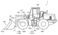
図1は、実施形態に基づくホイールローダ1の外観図である。図1に示されるように、ホイールローダ1は、車体102、作業機103、車輪104a,104b、および運転室105を備えている。ホイールローダ1は、車輪104a,104bが回転駆動されることにより自走可能であると共に、作業機103を用いて所望の作業を行うことができる。
<A. Overall configuration>
FIG. 1 is an external view of the
車体102は、前車体部102aと後車体部102bとを有している。前車体部102aと後車体部102bとは、互いに左右方向に揺動可能に連結されている。
The
前車体部102aと後車体部102bとに渡って、一対のステアリングシリンダ111a,111bが設けられている。ステアリングシリンダ111a,111bは、図示しないステアリングポンプからの作動油によって駆動される油圧シリンダである。ステアリングシリンダ111a,111bが伸縮することによって、前車体部102aが後車体部102bに対して揺動する。これにより、ホイールローダ1の進行方向が変更される。
A pair of
なお、図1では、ステアリングシリンダ111a,111bの一方のみを図示しており、他方を省略している。
In FIG. 1, only one of the
前車体部102aには、作業機103および一対の前輪104aが取り付けられている。作業機103は、車体102の前方に配設されている。作業機103は、油圧ポンプ8(図2参照)からの作動油によって駆動される。作業機103は、ブーム106と、一対のリフトシリンダ114a,114bと、バケット107と、ベルクランク109と、チルトシリンダ115とを有している。
A working
ブーム106は、前車体部102aに回転可能に支持されている。ブーム106の基端部が、ブームピン116によって、前車体部102aに揺動可能に取り付けられている。リフトシリンダ114a,114bの一端は前車体部102aに取り付けられている。リフトシリンダ114a,114bの他端は、ブーム106に取り付けられている。前車体部102aとブーム106とは、リフトシリンダ114a,114bにより連結されている。リフトシリンダ114a,114bが油圧ポンプ8からの作動油によって伸縮することによって、ブーム106がブームピン116を中心として上下に揺動する。
The
なお、図1では、リフトシリンダ114a,114bのうちの一方のみを図示しており、他方を省略している。
In FIG. 1, only one of the
バケット107は、ブーム106の先端に回転可能に支持されている。バケット107は、バケットピン117によって、ブーム106の先端部に揺動可能に指示されている。チルトシリンダ115の一端は前車体部102aに取り付けられている。チルトシリンダ115の他端はベルクランク109に取り付けられている。ベルクランク109とバケット107とは、図示しないリンク装置によって連結されている。前車体部102aとバケット107とは、チルトシリンダ115、ベルクランク109およびリンク装置により連結されている。チルトシリンダ115が、油圧ポンプ8からの作動油によって伸縮することによって、バケット107がバケットピン117を中心として上下に揺動する。
The
後車体部102bには、運転室105および一対の後輪104bが取り付けられている。運転室105は、車体102に搭載されている。運転室105には、オペレータが着座するシート、および後述する操作用の装置などが内装されている。
A driver's
前車体部102aには、詳細を後述する角度センサ144が設けられている。
<B.システム構成>
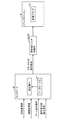
図2は、ホイールローダ1の構成を示す模式図である。図2に示すように、エンジン2から車輪104bまでの駆動力伝達経路90には、トランスファー6、トルクコンバータ3、トランスミッション4、パーキングブレーキ43およびサービスブレーキ40が設けられている。
The front
<B. System configuration>
FIG. 2 is a schematic diagram showing the configuration of the
エンジン2の出力軸は、トランスファー6に連結されている。トランスファー6は、油圧ポンプ8に連結される。
The output shaft of the
エンジン2の出力軸には、出力軸の回転数Neを検出するエンジン回転数センサ29が設けられている。エンジン回転数センサ29は、回転数Neを示す検出信号をコントローラ30に送信する。
The output shaft of the
エンジン2の出力の一部は、トランスファー6、トルクコンバータ3およびトランスミッション4を介して車輪104bに伝達される。これにより、ホイールローダ1は走行する。ホイールローダ1の走行速度Vtは、運転室105に備えられたアクセルペダル31によって制御可能である。アクセルペダル31がオペレータによって踏み込み操作されると、アクセル操作量センサ32は、アクセルペダル31の踏み込み操作量を示す検出信号をコントローラ30に送信する。
A part of the output of the
エンジン2の出力の残りは、トランスファー6を介して油圧ポンプ8に伝達される。これにより油圧ポンプ8が駆動される。油圧ポンプ8は、操作弁42aを介して、ブーム106を駆動する油圧アクチュエータ41aに作動油を供給する。ブーム106の上下動作は、運転室105に備えられたブーム操作レバー71aの操作によって制御可能である。また、油圧ポンプ8は、操作弁42bを介して、バケット107を駆動する油圧アクチュエータ41bに作動油を供給する。バケット107の動作は、運転室105に備えられたバケット操作レバー72aの操作によって制御可能である。
The rest of the output of the
このように、ホイールローダ1は、エンジン2の出力を利用して、掘削、後退、ダンプアプローチ、排土、後退という一連の作業を繰り返し行うことができる。これらの作業のうち、ダンプアプローチでは、土砂が積み込まれた作業機103を上昇させながらダンプトラック900に向かって微速前進する動作が行われる。
In this way, the
トルクコンバータ3は、トランスファー6とトランスミッション4との間に設けられる。トルクコンバータ3は、ポンプインペラ11と、タービンランナ12と、ステータ13と、ロックアップクラッチ14と、ワンウェイクラッチ15とを有する。ポンプインペラ11は、エンジン2に連結される。タービンランナ12は、トランスミッション4に連結される。ステータ13は、ポンプインペラ11とタービンランナ12との間に設けられる反動要素である。ロックアップクラッチ14は、ポンプインペラ11とタービンランナ12とを係合/開放(ニュートラルの状態)することによって、ポンプインペラ11とエンジン2との間の動力伝達を断接自在にする。ロックアップクラッチ14は、油圧作動する。ワンウェイクラッチ15は、ステータ13の一方向のみの回転を許容する。
The
トルクコンバータ3のポンプインペラ11には、ポンプインペラ11の回転数Ncを検出するトルクコンバータ入力回転数センサ44が設けられている。トルクコンバータ入力回転数センサ44は、回転数Ncを示す検出信号をコントローラ30に送信する。
The pump impeller 11 of the
トランスミッション4は、前進走行段に対応する前進クラッチ55(前進用のクラッチの一例)と、後進走行段に対応する後進クラッチ56とを有する。トランスミッション4は、1速〜4速の速度段それぞれに対応する1速クラッチ51、2速クラッチ52、3速クラッチ53および4速クラッチ54を有する。前進クラッチ55と後進クラッチ56とは、方向切換クラッチであり、1速〜4速クラッチ51〜54は、速度切換クラッチである。各クラッチ51〜56は、湿式多板の油圧クラッチで構成される。トランスミッション4は、ホイールローダの進行方向、必要な駆動力、および必要な走行速度Vtに応じて、各クラッチ51〜56を選択的に係合および開放させる。
The
トランスミッション4の各クラッチ51〜56の入力側と出力側との係合圧力は、各クラッチ51〜56に供給される作動油の油圧によって制御することができる。本実施形態では、各クラッチ51〜56は、供給される作動油の油圧が大きくなるに従って、開放から半係合を経て完全係合へと遷移する。各クラッチ51〜56の係合圧力は、コントローラ30から各クラッチ制御弁34〜39へ送信されたクラッチ油圧指令信号に応じて、各クラッチ制御弁34〜39が各クラッチ51〜56に供給するクラッチ油圧を調整することで制御される。なお、各クラッチ制御弁34〜39は、電子制御式比例電磁弁である。
The engagement pressure between the input side and the output side of each of the
トランスミッション4の入力軸には、入力軸の回転数Nt0を検出するトランスミッション入力軸回転数センサ45が設けられている。トランスミッション入力軸回転数センサ45は、回転数Nt0を示す検出信号をコントローラ30に送信する。
The input shaft of the
トランスミッション4の出力軸には、出力軸の回転数Nt2を検出するトランスミッション出力軸回転数センサ47が設けられている。トランスミッション出力軸回転数センサ47は、回転数Nt2を示す検出信号をコントローラ30に送信する。
The output shaft of the
パーキングブレーキ43は、トランスミッション4とサービスブレーキ40との間に配置される。パーキングブレーキ43は、出力軸に取り付けられる。パーキングブレーキ43は、主としてホイールローダを駐車させるためのネガティブブレーキである。パーキングブレーキ43は、制動状態と非制動状態に切替可能な湿式多板式のブレーキである。パーキングブレーキ43の係合圧力は、運転席に配置されたパーキングブレーキレバーの操作量によって調整可能である。
The
サービスブレーキ40は、パーキングブレーキ43と車輪104bの間に配置される。サービスブレーキ40は、車輪104bに連結される車軸に取り付けられる。サービスブレーキ40は、主として走行中の減速又は停止のために用いられるブレーキである。サービスブレーキ40は、制動状態と非制動状態に切替可能な湿式多板式のいわゆるポジティブブレーキである。サービスブレーキ40の係合圧力(すなわち、制動力)は、コントローラ30からブレーキ制御弁48へ送信されたブレーキ油圧指令信号に応じて、ブレーキ制御弁48がサービスブレーキ40に供給するブレーキ油圧を調整することで制御される。
The
コントローラ30は、アクセル操作量センサ32からの検出信号に基づいて、アクセル開度を調整、電子制御燃料噴射装置28に燃料噴射量指令信号を送信する。電子制御燃料噴射装置28は、噴射量指令信号を判断し、シリンダ内に噴射される燃料噴射量を調整し、エンジン2の出力(回転数)を制御する。なお、アクセル操作量センサ32は、アクセル開度センサとも称される。
The
ブーム操作レバー71aが操作されると、ブーム操作検出部71bは、コントローラ30に対して、当該操作に基づいたブーム操作信号を送信する。コントローラ30は、ブーム操作信号に応じて、操作弁42aにブーム油圧指令信号を送信する。操作弁42aはブーム油圧指令信号を判断し、油圧ポンプ8から油圧アクチュエータ41aへの作動油の供給量を制御する。ブーム106の動作速度は、ブーム操作レバー71aの操作量を調整することによって行われる。
When the boom operation lever 71a is operated, the boom operation detection unit 71b transmits a boom operation signal based on the operation to the
バケット操作レバー72aが操作されると、バケット操作検出部72bは、コントローラ30に対して、当該操作に基づいたバケット操作信号を送信する。コントローラ30は、バケット操作信号に応じて、操作弁42bにバケット油圧指令信号を送信する。操作弁42bはバケット油圧指令信号を判断し、油圧ポンプ8から油圧アクチュエータ41bへの作動油の供給量を制御する。バケット107の動作速度は、バケット操作レバー72aの操作量を調整することによって行われる。
When the
前後進切替レバー73aが操作されると、前後進切替検出部73bは、コントローラ30に対して、前後進切替レバー73aの操作位置に応じた前後進切替操作信号を送信する。コントローラ30は、前後進切替操作信号に応じて、前後進クラッチ制御弁34,35にクラッチ油圧指令信号を送信する。前後進クラッチ制御弁34,35はクラッチ油圧指令信号を判断し、前進クラッチ55および後進クラッチ56の一方を係合させる。
When the forward / backward switching
変速レバー74aが操作されると、変速検出部74bは、コントローラ30に対して、変速レバー74aの操作位置に応じた変速切替操作信号を送信する。コントローラ30は、変速切替操作信号に応じて、各変速クラッチ制御弁36〜39にクラッチ油圧指令信号を送信する。各変速クラッチ制御弁36〜39はクラッチ油圧指令信号を判断し、トランスミッション4の各速度段クラッチ(変速クラッチ)51〜54のいずれかを係合させる。
When the
ブレーキペダル75がオペレータによって踏み込み操作されると、ブレーキ操作量センサ76は、ブレーキペダル75の踏み込み操作量を示す検出信号をコントローラ30に送信する。
When the
コントローラ30は、ブレーキペダル75の踏み込み操作量に応じて、ブレーキ制御弁48にブレーキ油圧指令信号を送信する。ブレーキ制御弁48は、ブレーキ油圧指令信号を判断し、サービスブレーキ40に供給するブレーキ油圧を調整することでサービスブレーキ40の係合圧力を制御する。
The
コントローラ30は、車体102の傾きを検出する角度センサ144と接続されている。角度センサ144は、図1に示すように、前車体部102aに設けられている。角度センサ144は、車体102のピッチ角を検出し、検出信号をコントローラ30に入力する。ここで、ホイールローダ1の重心を通り左右方向に延びる軸回りの方向を、ピッチ方向と称する。ピッチ方向は、車体102の前端が車体102の重心に対して下降または上昇する方向をいう。ピッチ角とは、ピッチ方向における車体102の傾斜角度をいう。ピッチ角は、鉛直方向または水平方向などの基準面に対する車体102の前後方向の傾斜角度である。角度センサ144の利用方法については、後述する。
The
コントローラ30は、サービスブレーキ40の作動油の圧力を検出する圧力センサ7と接続されている。圧力センサ7による検出結果の利用方法については後述する。
The
モニタ81は、コントローラ30による表示制御によって各種の情報を表示する。さらに、モニタ81は、後述する設定値Fsを設定(変更)するための入力操作を受け付ける。なお、設定値Fsは、コントローラ30内のメモリに記憶されている。なお、モニタ81は、設定装置の一例である。
The
<C.ダンプアプローチの概要>
以下では、ホイールローダ1が少なくとも積荷状態でブーム106を上昇させながら前進している状況の一例として、ダンプアプローチを例に挙げて説明する。なお、ダンプトラックは、接近対象物の一例である。
<C. Overview of dump approach>
In the following, a dump approach will be described as an example of a situation in which the
なお、コントローラ30は、バケット107がチルト状態にあることを条件に、積荷状態と判定する。あるいは、コントローラ30は、バケット107がチルト状態にあって、かつリフトシリンダ114a,114b(ブームシリンダ)のボトム側の油圧が所定値以上であることを条件に、積荷状態と判定する。
The
図3は、ダンプアプローチの概要を説明するための模式図である。なお、ダンプアプローチとは、ホイールローダ1がブーム106を上昇させながらダンプトラックに近づくことをいう。詳しくは、ダンプアプローチとは、ホイールローダ1がダンプトラックに前進して近づいており、かつブームレバーがブーム上げ操作を受け付けている状態を指す。典型的には、ホイールローダ1がダンプトラックに2速で前進して近づいており、かつブーム操作レバー71aがブーム上げ操作を受け付けている状態を指す。
FIG. 3 is a schematic diagram for explaining the outline of the dump approach. The dump approach means that the
なお、以下では、説明の便宜上、ブーム106を上昇させるときには、ブーム上げの速度が一定であるもとして説明する。
In the following, for convenience of explanation, it is assumed that the boom raising speed is constant when the
また、ホイールローダ1は、図3(C)に基づいて説明するクラッチ油圧制御を実行する。以下では、当該クラッチ油圧制御の特徴を明確にするため、比較例として、このようなクラッチ油圧制御を実行しないとしたときのオペレータ操作(従来のオペレータ操作)を図3(A)および図3(B)に基づいて説明する。
Further, the
図3(A)は、ホイールローダとダンプトラックとの間の距離が十分に確保されている場合におけるオペレータ操作を説明するための図である。図3(A)に示すように、オペレータは、区間Q11では、アクセル操作を行う。具体的には、オペレータは、アクセルペダル31を踏む。さらに、オペレータは、区間Q11では、ブーム106を上げるために、ブーム操作レバー71aを操作する。これにより、区間Q11では、ホイールローダ1がダンプトラック900に向かって走行するとともに、ブーム上げ操作が実行される。
FIG. 3A is a diagram for explaining an operator operation when a sufficient distance between the wheel loader and the dump truck is secured. As shown in FIG. 3A, the operator operates the accelerator in the section Q11. Specifically, the operator steps on the
なお、オペレータが区間Q11でアクセル操作を行う理由は、ホイールローダ1を走行させるためというよりは、リフトシリンダ114a,114bに対して油圧を十分に供給するための意味合いが濃い。エンジン回転数を上げて、油圧ポンプからの作動油の出力を確保している。したがって、区間Q11で車速を落とすために、オペレータがブレーキペダルを踏み込んだとしても、オペレータはアクセルペダルを踏み続けている。
It should be noted that the reason why the operator operates the accelerator in the section Q11 has a strong meaning to sufficiently supply hydraulic pressure to the
区間Q11に続く区間Q12においては、オペレータは、アクセル操作をやめて、ブレーキ操作を行う。具体的には、オペレータは、アクセルペダル31を踏むのを止めて、ブレーキペダル75を踏む。これにより、オペレータは、ホイールローダ1をダンプトラック900の手前で停止させる。その後、オペレータは、バケット操作レバー72aを操作して、バケット107によって掬い取られた土砂をダンプトラック900の荷台に積み込む。
In the section Q12 following the section Q11, the operator stops the accelerator operation and performs the brake operation. Specifically, the operator stops stepping on the
このような一連の操作を行った場合、バケット107の通過軌跡は、典型的には、破線Laとして表される。
When such a series of operations is performed, the passing locus of the
図3(B)は、ホイールローダとダンプトラックとの間の距離が十分に確保されていない場合におけるオペレータ操作を説明するための図である。詳しくは、図3(B)は、後述する図3(C)で説明するクラッチ油圧制御を実行しない場合におけるオペレータ操作を説明するための図である。 FIG. 3B is a diagram for explaining an operator operation when the distance between the wheel loader and the dump truck is not sufficiently secured. More specifically, FIG. 3B is a diagram for explaining an operator operation when the clutch hydraulic pressure control described with reference to FIG. 3C, which will be described later, is not executed.
図3(B)に示すように、オペレータは、区間Q21では、ブレーキ操作を行うことなく、アクセル操作を行う。さらに、オペレータは、区間Q21では、ブーム106を上げるために、ブーム操作レバー71aを操作する。これにより、区間Q21では、ホイールローダ1がダンプトラック900に向かって走行するとともに、ブーム上げ操作が実行される。
As shown in FIG. 3B, the operator operates the accelerator in the section Q21 without performing the brake operation. Further, in the section Q21, the operator operates the boom operation lever 71a in order to raise the
区間Q21に続く区間Q22においては、オペレータは、アクセル操作ともに、ブレーキ操作を行う。具体的には、アクセルペダル31とブレーキペダル75とを同時に踏む。これにより、ホイールローダ1の前進速度を低下させつつ、区間Q21と同じブーム上げ速度でブーム106を上昇させる。
In the section Q22 following the section Q21, the operator performs the brake operation together with the accelerator operation. Specifically, the
オペレータは、ホイールローダ1とダンプトラック900との距離と、バケット107との位置を考慮して、ブレーキ操作を止めて、アクセル操作のみを行なう(区間Q23)。
The operator stops the brake operation and performs only the accelerator operation in consideration of the distance between the
区間Q23に続く区間Q24においては、オペレータは、アクセル操作をやめて、ブレーキ操作を行うことより、ホイールローダ1をダンプトラック900の手前で停止させる。その後、オペレータは、バケット操作レバー72aを操作して、バケット107によって掬い取られた土砂をダンプトラック900の荷台に積み込む。
In the section Q24 following the section Q23, the operator stops the accelerator operation and performs the brake operation to stop the
このような一連の操作を行った場合、バケット107の通過軌跡は、典型的には、破線Lbとして表される。
When such a series of operations is performed, the passing locus of the
図3(C)は、図3(B)と同様、ホイールローダとダンプトラックとの間の距離が十分に確保されていない場合におけるオペレータ操作を説明するための図である。詳しくは、図3(C)は、ダンプアプローチ時において、前進クラッチ55に供給する作動油の油圧を制御することによって前進クラッチ55を半係合状態にするクラッチ油圧制御を実行したときのバケット107の軌跡を説明するための図である。
FIG. 3C is a diagram for explaining an operator operation when the distance between the wheel loader and the dump truck is not sufficiently secured, as in FIG. 3B. Specifically, FIG. 3C shows the
図3(C)に示すように、オペレータは、区間Q31では、アクセル操作を行う。具体的には、オペレータは、アクセルペダル31を踏む。さらに、オペレータは、区間Q31では、ブーム106を上げるために、ブーム操作レバー71aを操作する。これにより、区間Q31では、ホイールローダ1がダンプトラック900に向かって走行するとともに、ブーム上げ操作が実行される。なお、区間Q31では、オペレータは、ブレーキ操作を行わない。
As shown in FIG. 3C, the operator operates the accelerator in the section Q31. Specifically, the operator steps on the
区間Q31においては、ホイールローダ1は、前進クラッチ55に供給する作動油の油圧を設定値まで低下させることによって前進クラッチ55を半係合状態にする。これにより、ホイールローダ1の車速は、前進クラッチ55が完全係合状態のときよりも低下する。ホイールローダ1の車速は、たとえば図3(B)の区間Q21および区間Q23の車速よりも低下する。その一方で、アクセルの操作量は、前進クラッチ55に供給する作動油の油圧を設定値まで低下させる直前と同じであるため、ブーム106を上昇させる速度は低下しない。このため、ホイールローダ1は、このようなクラッチ油圧制御によって、図3(A)の区間Q11よりも短い距離(区間Q31)であっても、バケット107をダンプトラック900の荷台の高さ以上に上昇させることができる。このような前進クラッチ55の油圧制御の詳細については、後述する(図4および図5)。
In the section Q31, the
なお、区間Q31に続く区間Q32においては、オペレータは、アクセル操作をやめて、ブレーキ操作を行う。具体的には、オペレータは、アクセルペダル31を踏むのを止めて、ブレーキペダル75を踏む。これにより、オペレータは、ホイールローダ1をダンプトラック900の手前で停止させる。その後、オペレータは、バケット操作レバー72aを操作して、バケット107によって掬い取られた土砂をダンプトラック900の荷台に積み込む。
In the section Q32 following the section Q31, the operator stops the accelerator operation and performs the brake operation. Specifically, the operator stops stepping on the
このような一連の操作を行った場合、バケット107の通過軌跡は、典型的には、破線Lcとして表される。
When such a series of operations is performed, the passing locus of the
なお、オペレータが、図3(C)に基づいて説明したクラッチ油圧制御を実行させるか否かを選択できる構成としてもよい。オペレータが、クラッチ油圧制御機能のオンオフを選択できるように、ホイールローダ1を構成してもよい。
The operator may be able to select whether or not to execute the clutch hydraulic pressure control described with reference to FIG. 3C. The
<D.ダンプアプローチ時のクラッチ油圧制御>
以下では、ダンプアプローチ時において実行される、前進クラッチ55に供給される作動油の油圧制御を、具体例を挙げて説明する。特に、図3(C)に基づいて説明したクラッチ油圧制御の詳細について説明する。なお、以下では、前進クラッチ55に供給する作動油の油圧を、「前進クラッチ55の油圧」とも称する。
<D. Clutch hydraulic control during dump approach>
Hereinafter, the hydraulic pressure control of the hydraulic oil supplied to the
図4は、積荷後進時とダンプアプローチ時とにおける、オペレータ操作およびホイールローダ1の状態を表したタイムチャートである。詳しくは、図4は、アクセル開度(図4(A))と、ブレーキペダル75の操作量(図4(B))と、ブーム操作レバー71aの操作量(図4(C))と、ブーム角度(図4(D))と、前進クラッチ55の油圧(図4(E))と、ホイールローダ1の車速(図4(F))とを、横軸を同一の時間軸として表したグラフである。
FIG. 4 is a time chart showing the state of the operator operation and the
図4に示すように、ホイールローダ1は、時刻t0からt2の間に、積荷後進をする。なお、「積荷後進」とは、地山等からバケット107で土砂を掬い取った後に、ダンプアプローチを開始する位置まで後進することをいう。
As shown in FIG. 4, the
まず、アクセル開度と、ブレーキペダル75の操作量と、ブーム操作レバー71aの操作量と、ブーム角度との関係について説明する。
First, the relationship between the accelerator opening, the operation amount of the
積荷後進時(時刻t0〜t2)において、オペレータは、アクセルペダル31をスロットルバルブが全開(フルスロットル)となるまで踏み込む。なお、この場合、オペレータは、ブレーキペダル75を操作しない。オペレータは、一例として、ダンプアプローチ開始位置まで近づくと、ブーム上げの時間を稼ぐために、時刻t1(t0<t1<t2)においてブーム操作レバー71aを最大量操作する。これにより、ブーム106は、上昇し始める。
When the load is moving backward (time t0 to t2), the operator depresses the
オペレータは、時刻t2で後進を停止し、ダンプアプローチを開始する。ホイールローダ1は、前進しながら、ブーム上げ操作を実行する。ダンプアプローチ中においても、オペレータは、積荷後進時から継続してアクセルペダル31を踏む。さらに、オペレータは、ブーム106が最大角度まで上昇しており、かつホイールローダ1がダンプトラックの傍まで到達すると、ブレーキペダル75の踏込を開始する。
The operator stops moving backward at time t2 and starts the dump approach. The
ダンプアプローチが終了すると(時刻t3)と、オペレータは、アクセルペダル31の操作を停止する。さらに、オペレータは、ブレーキペダル75を所定の位置まで踏み込み、その状態を維持する。また、オペレータは、時刻t3においてブーム106が最大角度まで上昇しているため、ブーム操作レバー71aの操作を停止する。
When the dump approach ends (time t3), the operator stops the operation of the
次に、時刻t0以降における、前進クラッチ55の油圧とホイールローダ1の車速との関係について説明する。
Next, the relationship between the hydraulic pressure of the
ホイールローダ1のコントローラ30は、オペレータ操作によって前後進切替レバー73aが前進側に切り替えられると、後進クラッチ56を中立状態するための油圧制御と、前進クラッチ55を中立状態から完全係合状態にするための油圧制御を開始する。これにより、時刻t2の時点で、前進クラッチ55の油圧が所定の保持圧Fhとなり、前進クラッチ55は完全係合状態となる。その後、ダンプアプローチが開始される。
When the forward / backward switching
コントローラ30は、ダンプアプローチが開始されると、前進クラッチ55の油圧を保持圧Fhから、前進クラッチ55が半係合状態となる設定値Fsまで前進クラッチ55の油圧を低下させる制御を行う。コントローラ30は、ダンプアプローチが終了すると、前進クラッチ55の油圧を、設定値Fsから保持圧Fhまで徐々に上昇させる制御を行う。なお、図4(E)においては、時刻t4において、前進クラッチ55の油圧が保持圧Fhとなっている。
When the dump approach is started, the
ホイールローダ1の前進時の車速は、少なくとも時刻t2〜t3の間において前進クラッチ55が半係合状態となっているため、完全係合状態となっているときよりも低下する。なお、図4(F)における破線は、時刻t2〜t4において前進クラッチ55の油圧が保持圧Fhであったと仮定した場合のホイールローダ1の速度を表している。
The vehicle speed of the
以下においては、前進クラッチ55の油圧制御について、時刻t0〜t2の間の制御状態を「状態α」と、時刻t2〜t3の間の制御状態を「状態β」と、時刻t3〜t4の間の制御状態を「状態γ」とも称する。なお、状態γの後は状態αに遷移する。
In the following, regarding the hydraulic control of the
図5は、図4に基づいて説明したクラッチ油圧制御を実現するための具体的構成を説明するための図である。 FIG. 5 is a diagram for explaining a specific configuration for realizing the clutch hydraulic pressure control described with reference to FIG. 4.
図5に示すように、コントローラ30は、データテーブルT4と、設定値Fsとを記憶している。データテーブルT4には、前進クラッチ55の油圧とクラッチ油圧指令信号の電流値との対応関係が規定されている。
As shown in FIG. 5, the
コントローラ30は、前後進切替操作信号と、変速切替操作信号と、ブーム操作信号とに基づき、ダンプアプローチ中か否かを判断する。典型的には、変速段が2速であって、かつブームを上げながら前進している場合には、コントローラ30は、ホイールローダ1がダンプアプローチ状態にあると判断する。
The
コントローラ30は、ダンプアプローチ中であると判断すると、データテーブルT4を参照し、設定値Fsに対応する電流値のクラッチ油圧指令信号を生成する。コントローラ30は、生成されたクラッチ油圧指令信号を前後進クラッチ制御弁34,35に送信される。これにより、トランスミッション4内の前進クラッチ55には、作動油が供給され、前進クラッチ55の油圧は、設定値Fsとなる。
When the
また、モニタ81が設定値Fsの値を変更するためのオペレータ操作を受け付けると、モニタ81は、コントローラ30に対して、設定値切替操作信号を送信する。コントローラ30は、設定値切替操作信号を受信すると、設定値切替操作信号に応じた値となるように設定値Fsを変更する。なお、モニタ81によって設定され得る設定値Fsは、前進クラッチ55が半係合状態となる範囲内の値である。
Further, when the
コントローラ30は、たとえば、モニタ81に複数のオブジェクト(画像)を表示し、当該複数のオブジェクトのうちの1つが選択されることにより、当該オブジェクトに対応付けられた値を設定値Fsとする。複数のオブジェクトとしては、設定レベルを各々表記したオブジェクトが例として挙げられる。たとえば、「設定値大」、「設定値中」、「設定値小」、あるいは、「レベル3」、「レベル2」、「レベル1」といった表示が、オブジェクトの例として挙げる。
The
なお、設定値Fsの設定は、モニタ81によるものに限定されず、設定値Fsを設定するためのダイヤルが運転室105に備えられていてもよい。
The setting of the set value Fs is not limited to that by the
以上のように、コントローラ30は、ホイールローダ1がブーム106を上昇させながらダンプトラック900に前進して近づいていること(ダンプアプローチ中であること)を条件に、前進クラッチ55に供給する作動油の油圧を制御することによって前進クラッチ55を半係合状態にするクラッチ油圧制御を実行する。
As described above, the
ところで、ダンプアプローチ中に前進クラッチ55が半係合状態となると、前進クラッチ55を通過する通過トルクが小さくなる。それゆえ、ホイールローダ1の牽引力も低下する。したがって、ホイールローダ1では、前進クラッチ55の油圧を半係合状態となる設定値Fsまで低下させない場合とは異なり、ブレーキの引きずり度合いを小さくすることが可能となる。その結果、ホイールローダ1では、前進クラッチ55の油圧を半係合状態となる設定値Fsまで低下させない場合に比べて、サービスブレーキ40のブレーキパッドの摩耗を低減できるとともに、ホイールローダ1の燃費を低減できる。
By the way, when the
特に、ホイールローダとダンプトラックとの間の距離が十分でない場合においても、ダンプトラック900の直前におけるブレーキ操作を除けば、ブレーキ操作が不要になる。このため、ブレーキパッドの摩耗を低減できるとともに、ホイールローダ1の燃費を低減できる。さらに、ダンプアプローチ時において、アクセルペダル31とブレーキペダル75との同時操作をなくすことができるため、オペレータ操作が簡単になる。
In particular, even when the distance between the wheel loader and the dump truck is not sufficient, the brake operation becomes unnecessary except for the brake operation immediately before the
このように、ホイールローダ1によれば、作業効率を向上させることができる。
さらに詳しくは、コントローラ30は、ダンプアプローチ中は、前進クラッチ55の油圧を一定の値を維持するように制御する。これによれば、前記クラッチ55の油圧の値を一定に維持しない構成に比べて、オペレータは、ホイールローダ1の前進速度を細やかに調整可能となる。
As described above, according to the
More specifically, the
また、モニタ81は、上記のように設定値Fを設定するためのオペレータ操作を受け付ける。これによれば、ダンプアプローチ時におけるホイールローダ1の前進速度を、オペレータが好みの設定に変更することができる。
Further, the
ところで、コントローラ30は、上述したクラッチ油圧制御時に、クラッチの通過トルクに基づいて、クラッチが半係合状態および完全係合状態のいずれの状態であるかを判定することができる。
By the way, the
詳しくは、コントローラ30は、前進クラッチ55が含まれるトランスミッション4の入力軸の回転数を検出するトランスミッション入力軸回転数センサ45(第1の回転数センサ)の検出値と、トランスミッションの出力軸の回転数を検出するトランスミッション出力軸回転数センサ47(第2の回転数センサ)の検出値とに基づいて、前進クラッチ55が半係合状態および完全係合状態のいずれの状態であるかを判定することができる。
Specifically, the
より詳しくは、コントローラ30は、トランスミッション入力軸回転数センサ45による検出値から出力軸の回転数を推定する。コントローラ30は、推定された回転数と、トランスミッション出力軸回転数センサ47による検出値との差を算出する。コントローラ30は、算出された差が所定の閾値以上となると、前進クラッチ55が半係合状態になったと判定する。
More specifically, the
<E.制御構造>
図6は、前進クラッチ55の制御状態の遷移を表した状態遷移図である。
<E. Control structure>
FIG. 6 is a state transition diagram showing the transition of the control state of the
図6に示すように、コントローラ30は、前進クラッチ55の油圧の制御状態を、初期状態から状態α(図4の時刻t0〜t2の状態)に遷移させる。状態αのときには、コントローラ30は、上述したような前進クラッチ55の油圧を設定値Fsまで低下させるクラッチ油圧制御を行わない。
As shown in FIG. 6, the
コントローラ30は、状態αにおいてダンプアプローチが開始されると、前進クラッチ55の制御状態を状態αから状態β(図4の時刻t2〜t3の状態)に遷移させる。状態βでは、上述したように、コントローラ30は、前進クラッチ55の油圧を設定値Fsまで低下させるクラッチ油圧制御を実行する。
When the dump approach is started in the state α, the
コントローラ30は、状態βにおいてダンプアプローチが終了すると、前進クラッチ55の制御状態を状態βから状態γ(図4の時刻t3〜t4の状態)に遷移させる。状態γでは、上述したように、コントローラ30は、前進クラッチ55の油圧を設定値Fsから徐々に上昇させる制御を行う。
When the dump approach ends in the state β, the
コントローラ30は、状態γにおいて前進クラッチ55の油圧が保持圧Fhに到達すると、前進クラッチ55の制御状態を状態γから状態αに遷移させる。コントローラ30は、状態γにおいて前進クラッチ55の油圧が保持圧Fhに到達するまでにダンプアプローチが再開されると、前進クラッチ55の制御状態を状態γから状態βに遷移させる。
When the hydraulic pressure of the
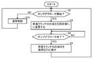
図7は、ホイールローダ1の前進クラッチ55の油圧制御の処理の流れの一例を説明するためのフロー図である。
FIG. 7 is a flow chart for explaining an example of the flow of hydraulic control processing of the
図7に示すように、コントローラ30は、ステップS2において、ダンプアプローチが開始されたか否かを判断する。コントローラ30は、ダンプアプローチが開始されたと判断した場合(ステップS2においてYES)、ステップS4において、前進クラッチ55の油圧を設定値Fsに変更する制御を行う。コントローラ30は、ダンプアプローチが開始されていないと判断した場合(ステップS2においてNO)、ステップS10に進み、通常制御を継続する。
As shown in FIG. 7, the
コントローラ30は、ステップS6において、ダンプアプローチが終了したか否かを判断する。コントローラ30は、ダンプアプローチが終了したと判断した場合(ステップS6においてYES)、ステップS8において、前進クラッチ55の油圧を保持圧Fhに戻す制御を行う。なお、コントローラ30は、ダンプアプローチが終了していないと判断した場合(ステップS6においてNO)、ステップS6に戻り、ステップS6の処理を繰り返す。
The
<F.小括>
(1)ホイールローダ1は、ブーム106と、前進クラッチ55と、前進クラッチ55に供給される作動油の油圧を制御するコントローラ30とを備える。コントローラ30は、ホイールローダ1が少なくとも積荷状態でブーム106を上昇させながら前進していることを条件に、前進クラッチ55の油圧を制御することによって前進クラッチ55を半係合状態にするクラッチ油圧制御を実行する。詳しくは、コントローラ30は、ホイールローダ1が積荷状態でダンプトラック900に前進して近づいており、かつブーム操作レバー71aがブーム上げ操作を受け付けていることを条件に、前進クラッチ55の油圧を制御することによって前進クラッチ55を半係合状態にするクラッチ油圧制御を実行する。
<F. Summary>
(1) The
ダンプアプローチ中に前進クラッチ55が半係合状態となると、前進クラッチ55を通過する通過トルクが小さくなる。それゆえ、ホイールローダ1の牽引力も低下する。したがって、ホイールローダ1では、前進クラッチ55の油圧を半係合状態まで低下させない場合とは異なり、ブレーキの引きずり度合いを小さくすることが可能となる。その結果、ホイールローダ1では、前進クラッチ55の油圧を半係合状態まで低下させない場合に比べて、サービスブレーキ40のブレーキパッドの摩耗を低減できるとともに、ホイールローダ1の燃費を低減できる。
When the
特に、ホイールローダとダンプトラックとの間の距離が十分でない場合においても、ダンプトラック900の直前におけるブレーキ操作を除けば、ブレーキ操作が不要になる。このため、ブレーキパッドの摩耗を低減できるとともに、ホイールローダ1の燃費を低減できる。さらに、ダンプアプローチ時において、アクセルペダル31とブレーキペダル75との同時操作をなくすことができるため、オペレータ操作が簡単になる。
In particular, even when the distance between the wheel loader and the dump truck is not sufficient, the brake operation becomes unnecessary except for the brake operation immediately before the
このように、ホイールローダ1によれば、作業効率を向上させることができる。
(2)コントローラ30は、ダンプアプローチにおいては、前進クラッチ55の油圧を、一定の設定値Fsを維持するように制御する。これによれば、一定の設定値Fsを維持しない構成に比べて、オペレータは、ホイールローダ1の前進速度を安定させることができる。
As described above, according to the
(2) In the dump approach, the
(3)コントローラ30は、設定値Fsを設定するためのオペレータ操作を受け付けるモニタ81をさらに備える。これによれば、ダンプアプローチ時におけるホイールローダ1の前進速度を、オペレータが好みの設定に変更することができる。
(3) The
(4)コントローラ30は、ホイールローダ1がダンプトラック900に近づくための前進を終了すると、上述したクラッチ油圧制御を停止する。これによれば、ホイールローダがダンプトラックに近づくための前進を終了すると、前進クラッチ55の油圧をクラッチ油圧制御の開始前の値(保持圧Fh)に戻すことができる。
(4) When the
(5)ダンプアプローチの際には、オペレータは、一般的には、速度段クラッチを2速に入れる。そこで、コントローラ30は、ホイールローダ1がダンプトラック900に2速の速度段(所定の速度段の一例)で前進して近づいており、かつブーム操作レバー71aがブーム上げ操作を受け付けていることを条件に、前進クラッチ55の油圧を制御することによって前進クラッチ55を半係合状態にするクラッチ油圧制御を実行してもよい。
(5) During the dump approach, the operator generally engages the speed stage clutch in second gear. Therefore, the
<G.変形例>
(g1.速度段クラッチへの適用)
上述した実施の形態では、コントローラ30は、ダンプアプローチ中であることを条件に、前進クラッチ55に供給する作動油の油圧を制御することによって前進クラッチ55を半係合状態にするクラッチ油圧制御を実行した。
<G. Modification example>
(G1. Application to speed stage clutch)
In the above-described embodiment, the
しかしながら、これに限定されるものではなく、コントローラ30は、ダンプアプローチ中であることを条件に、速度段クラッチ51〜54の油圧を制御することによって速度段クラッチ51〜54を半係合状態にするクラッチ油圧制御を実行してもよい。
However, the present invention is not limited to this, and the
詳しくは、コントローラ30は、ダンプアプローチ中であることを条件に、速度段クラッチ51〜54のうち変速レバー74aの操作位置に応じた速度段クラッチの油圧を制御することによって当該速度段クラッチを半係合状態にするクラッチ油圧制御を実行してもよい。
Specifically, the
このような構成によっても、速度段クラッチ51〜54の油圧を制御することによって速度段クラッチ51〜54を半係合状態させる場合と同様、作業効率を向上させることができる。
Even with such a configuration, the work efficiency can be improved as in the case where the
(g2.測距センサの利用)
上記の実施の形態においては、コントローラ30は、ホイールローダ1がダンプトラック900に前進して近づいていることを条件に、前進クラッチ55の油圧を一定値である設定値Fsに制御することによって前進クラッチを半係合状態にするクラッチ油圧制御を実行した。以下では、コントローラ30が、前進クラッチ55の油圧を、設定値Fsを維持するのではなく、ホイールローダ1Aとダンプトラック900との間の距離に応じた値とする構成について説明する。
(G2. Use of distance measurement sensor)
In the above embodiment, the
図8は、本変形例に係るホイールローダの外観図である。図8に示すように、ホイールローダ1Aは、運転室105の屋根の上に測距センサ149を備える。ホイールローダ1Aのハードウェア構成は、測距センサ149を備える以外は、ホイールローダ1と同じである。なお、測距センサ149の位置は、屋根の上に限定されるものではない。
FIG. 8 is an external view of the wheel loader according to this modification. As shown in FIG. 8, the
測距センサ149は、ホイールローダ1Aと前方の対象物との間の距離を測定するためのセンサである。測距センサ149は、ダンプアプローチ時には、ダンプトラック900との間の距離が測定されることになる。なお、測距センサ149は、レーザによって距離を測定する構成であってもよいし、撮像によって距離を測定する構成であってもよい。
The
コントローラ30は、測距センサ149から、測定結果を取得する。コントローラ30は、ダンプアプローチが開始されると、前進クラッチ55の油圧を測距センサ149によって測定された距離に基づき制御することによって、前進クラッチ55を半係合状態にするクラッチ油圧制御を実行する。
The
たとえば、コントローラ30は、測定された距離Dが距離Daの場合には、前進クラッチ55に供給する作動油の油圧を第1の油圧に設定し、測定された距離Dが距離Daよりも短い距離Dbの場合には、前進クラッチ55の油圧を上記第1の油圧よりも低い第2の油圧に設定する。
For example, when the measured distance D is the distance Da, the
図9は、測定された距離Dと、コントローラ30が設定する前進クラッチ55の油圧との関係を表した図である。図9(A)は、第1の例を表しており、図9(B)は、第2の例を表している。
FIG. 9 is a diagram showing the relationship between the measured distance D and the hydraulic pressure of the forward clutch 55 set by the
図9(A)に示すように、コントローラ30は、ホイールローダ1とダンプトラック900との間の距離Dが距離D1のときには、前進クラッチ55の油圧を、前進クラッチ55が半係合状態となる油圧Fpに制御する。その後、コントローラ30は、ホイールローダ1とダンプトラック900との間の距離が短くなるにつれて、前進クラッチ55の油圧を油圧Fpから徐々に低下させる。図9(A)では、ホイールローダ1とダンプトラック900との間の距離Dがゼロのときには、前進クラッチ55の油圧がFqとなるように設定されている。
As shown in FIG. 9A, when the distance D between the
このように、コントローラ30は、ダンプアプローチ時において、ホイールローダ1とダンプトラック900との間の距離Dが短くなるにつれて前進クラッチ55の油圧を低下させることにより、ホイールローダ1の車速をダンプトラック900に近づくにつれて低下させることが可能となる。
As described above, the
前進クラッチ55の油圧を距離Dに基づき制御する方法は、図9(A)に示した態様に限定されるものではない。たとえば、図9(B)に示すように、コントローラ30は、距離DがD2からD3(D3<D2<D1))の範囲内において、前進クラッチ55の油圧を測距センサ149によって測定された距離Dに応じて変化する構成としてもよい。なお、この場合、距離DがD1からD2(D2<D1)の範囲内においては前進クラッチ55の油圧が一定値Fpとなり、かつ距離DがD3(D3<D2)以下の場合には前進クラッチ55の油圧が一定値Fqとなるように、前進クラッチ55の油圧が制御される。
The method of controlling the hydraulic pressure of the forward clutch 55 based on the distance D is not limited to the embodiment shown in FIG. 9A. For example, as shown in FIG. 9B, the
なお、コントローラ30は、ホイールローダ1とダンプトラック900との間の距離Dがゼロのときに、前進クラッチ55が中立状態となるように、前進クラッチ55の油圧を制御してもよい。あるいは、コントローラ30は、距離Dが所定の閾値以下のときには、前進クラッチ55が中立状態となるように、前進クラッチ55の油圧を制御してもよい。
The
このように、油圧を測距センサ149によって測定された距離Dに基づき制御する構成は、前進クラッチ55の油圧制御のみならず、上述したように、速度段クラッチ51〜54にも適用できる。また、当該構成は、駆動力伝達経路90(パワートレインの一例)に含まれている、図示しないインペラクラッチ等の他のクラッチにも適用できる。さらに、仮にホイールローダ1Aにモジュレーションクラッチを搭載した場合には、上記構成を当該モジュレーションクラッチにも適用できる。
As described above, the configuration in which the hydraulic pressure is controlled based on the distance D measured by the
以上のように、コントローラ30は、ホイールローダ1がダンプトラック900に前進して近づいていることを条件に、駆動力伝達経路90内の複数のクラッチのうちの所定のクラッチに供給する作動油の油圧を制御することによって当該所定のクラッチを半係合状態にするクラッチ油圧制御を実行する。コントローラ30は、当該クラッチ油圧制御では、上記所定のクラッチに供給する作動油の油圧を測距センサ149により測定された距離に基づき制御する。
As described above, the
これによれば、ホイールローダ1とダンプトラック900との間の距離Dが短くなるにつれて当該所定のクラッチの油圧を低下させることにより、ホイールローダ1の車速をダンプトラック900に近づくにつれて低下させることが可能となる。
According to this, as the distance D between the
(g3.角度センサ144の利用)
コントローラ30は、車体102の傾きが予め定められた角度未満であることを条件に、前進クラッチ55の油圧を制御することによって前進クラッチ55を半係合状態にするクラッチ油圧制御を実行してもよい。
(G3. Use of angle sensor 144)
Even if the
坂道等の傾斜地では、前進クラッチ55等が滑っている時間が長くなるため、熱負荷が大きくなる。しかしながら、上記のような構成によれば、鉛直方向または水平方向などの基準面に対して車体102の前後方向に車体102が予め定められた角度以上傾斜している場合、ダンプアプローチの条件が成立していても、コントローラ30は、上記のクラッチ油圧制御を実行しない。したがって、傾斜地において熱負荷が大きくなることを低減できる。
On slopes such as slopes, the heat load increases because the
なお、コントローラ30は、車体102の傾きが予め定められた角度以上であるか否かによって、傾斜地を走行中であるか否かを判断できる。また、車体の傾きは、角度センサ144による検出結果に基づき判断できる。
The
(g4.発熱対策)
次に、ダンプアプローチ中に前進クラッチ55が半係合状態となることによって、前進クラッチ55において熱が発生する。以下では、このような熱の発生量を抑制するための構成について説明する。
(G4. Measures against heat generation)
Next, heat is generated in the forward clutch 55 when the
コントローラ30は、前進クラッチ55の使用状態を監視する。具体的に、コントローラ30は、前進クラッチ55の発熱量Qを算出する。前進クラッチ55の発熱量Qは、放熱量R(t)とクラッチ発熱率qとクラッチ滑らせ時間Δtとを用いた以下の式(1)によって算出することができる。
The
![]()
![]()
また、クラッチ発熱率qは、以下の式(2)によって算出することができる。
クラッチ発熱率q=摩擦係数×相対回転数×クラッチ油圧 ・・・(2)
式(1)において、クラッチ滑らせ時間Δtとは、前進クラッチ55がブレーキペダル75の操作量Pに応じて半係合状態を継続している時間である。前進クラッチ55が完全係合又は切断されたとき、クラッチ滑らせ時間Δtは0に戻る。
Further, the clutch heat generation rate q can be calculated by the following equation (2).
Clutch heat generation rate q = coefficient of friction x relative rotation speed x clutch oil pressure ... (2)
In the equation (1), the clutch slip time Δt is the time during which the
式(2)において、摩擦係数とは、クラッチプレートの摩擦材の摩擦係数である。相対回転数とは、エンジン回転数センサが検出したエンジン回転数Neと、トルクコンバータ入力回転数センサが検出したポンプインペラ回転数Ncとの差分である。また、相対回転数とは、入力側と出力側の回転数差である。クラッチ油圧とは、クラッチプレート間に生じる面圧である。前後進クラッチ制御弁34,35には電子制御式比例電磁弁を使用しているため、クラッチ油圧は、コントローラ30から前後進クラッチ制御弁34,35に送信されたクラッチ油圧指令信号から読み取ることができる。
In the formula (2), the friction coefficient is the friction coefficient of the friction material of the clutch plate. The relative rotation speed is the difference between the engine rotation speed Ne detected by the engine rotation speed sensor and the pump impeller rotation speed Nc detected by the torque converter input rotation speed sensor. The relative rotation speed is the difference in rotation speed between the input side and the output side. The clutch oil pressure is the surface pressure generated between the clutch plates. Since an electronically controlled proportional solenoid valve is used for the forward / backward
コントローラ30は、発熱量Qが閾値Qmax未満であるか否かを判定する。発熱量QがQmax以上である場合、前進クラッチ55の油圧を制御することによって前進クラッチ55を半係合状態にするクラッチ油圧制御を停止する。これによれば、前進クラッチ55の発熱量Qを低下させることができる。
The
あるいは、コントローラ30は、当該クラッチ油圧制御を停止させるための予め定められた報知を出力装置(表示装置またはスピーカ)に行なわせるための制御信号を生成してもよい。これによれば、コントローラ30は、前進クラッチ55の発熱量Qを低下させる契機付をオペレータに与えることができる。
Alternatively, the
(g5.過大滑りの検知)
コントローラ30は、前進クラッチ55が半係合状態において、前進クラッチ55における前後の軸の回転数差が所定の閾値以上となった場合、図4(E)に示したように前進クラッチ55の油圧を設定値Fsとするクラッチ油圧制御を停止する。これによれば、前進クラッチ55における前後の軸の回転数差が所定の閾値以上となる大きな滑りを検出すると、前進クラッチ55の油圧が高くなる。したがって、前進クラッチ55の滑りが少なくなる。
(G5. Detection of excessive slip)
When the
特に、上記のような大きな滑りは、積荷後進からダンプアプローチへの遷移直後(図4に示した時刻t2の直後)に起こり得る。それゆえ、大きな滑りが起こった場合に、クラッチ油圧制御を停止させることより、ショックオペレータが感じるショックを低減できる。 In particular, the above-mentioned large slip may occur immediately after the transition from the reverse load to the dump approach (immediately after the time t2 shown in FIG. 4). Therefore, when a large slip occurs, the shock felt by the shock operator can be reduced by stopping the clutch hydraulic control.
(g6.クラッチ油圧制御の開始条件)
積荷状態でブーム106を上昇させながら前進している(ダンプアプローチ中であること)に加えて、バケット107に所定の重量以上の土砂等の積荷を抱えていることが検出されたことを条件に、前進クラッチ55に供給する作動油の油圧を制御することによって前進クラッチ55を半係合状態にするクラッチ油圧制御を実行するように、コントローラ30を構成してもよい。たとえば、コントローラ30は、バケット107が所定の重量以上の土砂等の積荷を抱えているか否かを、リフトシリンダ114a,114bのボトム圧(油圧)が所定値以上であるか否かで判断できる。
(G6. Conditions for starting clutch hydraulic control)
In addition to moving forward while raising the
今回開示された実施の形態は例示であって、上記内容のみに制限されるものではない。本発明の範囲は特許請求の範囲によって示され、特許請求の範囲と均等の意味および範囲内でのすべての変更が含まれることが意図される。 The embodiments disclosed this time are examples, and are not limited to the above contents. The scope of the present invention is indicated by the scope of claims and is intended to include all modifications within the meaning and scope equivalent to the scope of claims.
1,1A ホイールローダ、2 エンジン、3 トルクコンバータ、4 トランスミッション、6 トランスファー、7 圧力センサ、8 油圧ポンプ、11 ポンプインペラ、12 タービンランナ、13 ステータ、14 ロックアップクラッチ、15 ワンウェイクラッチ、28 電子制御燃料噴射装置、29 エンジン回転数センサ、30 コントローラ、31 アクセルペダル、32 アクセル操作量センサ、34,35 前後進クラッチ制御弁、36,39 変速クラッチ制御弁、40 サービスブレーキ、41a,41b 油圧アクチュエータ、42a,42b 操作弁、43 パーキングブレーキ、44 トルクコンバータ入力回転数センサ、45 トランスミッション入力軸回転数センサ、47 トランスミッション出力軸回転数センサ、48 ブレーキ制御弁、51〜54 速度段クラッチ、55 前進クラッチ、56 後進クラッチ、71a ブーム操作レバー、71b ブーム操作検出部、72a バケット操作レバー、72b バケット操作検出部、73a 前後進切替レバー、73b 前後進切替検出部、74a 変速レバー、74b 変速検出部、75 ブレーキペダル、76 ブレーキ操作量センサ、81 モニタ、90 駆動力伝達経路、102 車体、102a 前車体部、102b 後車体部、103 作業機、104a 前輪、104b 後輪、105 運転室、106 ブーム、107 バケット、109 ベルクランク、111a,111b ステアリングシリンダ、114a,114b リフトシリンダ、115 チルトシリンダ、116 ブームピン、117 バケットピン、144 角度センサ、149 測距センサ、900 ダンプトラック。 1,1A Wheel loader, 2 engine, 3 torque converter, 4 transmission, 6 transfer, 7 pressure sensor, 8 hydraulic pump, 11 pump impeller, 12 turbine runner, 13 stator, 14 lockup clutch, 15 one-way clutch, 28 electronic control Fuel injection device, 29 engine rotation speed sensor, 30 controller, 31 accelerator pedal, 32 accelerator operation amount sensor, 34,35 forward / backward clutch control valve, 36,39 speed change clutch control valve, 40 service brake, 41a, 41b hydraulic actuator, 42a, 42b operation valve, 43 parking brake, 44 torque converter input rotation speed sensor, 45 transmission input shaft rotation speed sensor, 47 transmission output shaft rotation speed sensor, 48 brake control valve, 51-54 speed stage clutch, 55 forward clutch, 56 Reverse clutch, 71a boom operation lever, 71b boom operation detection unit, 72a bucket operation lever, 72b bucket operation detection unit, 73a forward / backward switching lever, 73b forward / backward switching detection unit, 74a shift lever, 74b shift detection unit, 75 brake Pedal, 76 Brake operation amount sensor, 81 monitor, 90 Driving force transmission path, 102 car body, 102a front car body, 102b rear car body, 103 work machine, 104a front wheel, 104b rear wheel, 105 cab, 106 boom, 107 bucket , 109 Bell Clutch, 111a, 111b Steering Cylinder, 114a, 114b Lift Cylinder, 115 Tilt Cylinder, 116 Boom Pin, 117 Bucket Pin, 144 Angle Sensor, 149 Distance Measuring Sensor, 900 Dump Truck.
Claims (18)
ブームと、
前進用または速度段用のクラッチを含むトランスミッションと、
前記クラッチに供給される作動油の油圧を制御するコントローラとを備え、
前記コントローラは、前記ホイールローダが少なくとも積荷状態で前記ブームを上昇させながら前進していることを条件に、前記ホイールローダの速度を安定させるために前記クラッチに供給する作動油の油圧を一定の値を維持するように制御することによって、前記クラッチを半係合状態にするクラッチ油圧制御を実行する、ホイールローダ。 It ’s a wheel loader,
With the boom
With a transmission that includes a clutch for forward or speed stages,
It is equipped with a controller that controls the hydraulic pressure of the hydraulic oil supplied to the clutch.
The controller sets a constant value of the hydraulic pressure of the hydraulic oil supplied to the clutch in order to stabilize the speed of the wheel loader, provided that the wheel loader is moving forward while raising the boom at least in a loaded state. A wheel loader that performs clutch hydraulic control to bring the clutch into a semi-engaged state by controlling to maintain.
ブームと、
前進用または速度段用のクラッチと、
前記クラッチに供給される作動油の油圧を制御するコントローラと、
測距センサとを備え、
前記コントローラは、前記ホイールローダが少なくとも積荷状態で前記ブームを上昇させながら前進していることを条件に、前記クラッチに供給する作動油の油圧を制御することによって前記クラッチを半係合状態にするクラッチ油圧制御を実行し、
前記測距センサは、前記ホイールローダが接近対象物に前進して近づいているときには、前記ホイールローダと前記接近対象物との間の距離を測定し、
前記コントローラは、前記クラッチ油圧制御では、前記クラッチに供給する作動油の油圧を前記測距センサにより測定された距離に基づき制御する、ホイールローダ。 It ’s a wheel loader,
With the boom
With a clutch for forward or speed stage,
A controller that controls the hydraulic pressure of the hydraulic oil supplied to the clutch,
Equipped with a distance measuring sensor
The controller puts the clutch in a semi-engaged state by controlling the hydraulic pressure of the hydraulic oil supplied to the clutch, provided that the wheel loader is moving forward while raising the boom at least in a loaded state. Perform clutch hydraulic control,
The distance measuring sensor measures the distance between the wheel loader and the approaching object when the wheel loader advances and approaches the approaching object.
In the clutch hydraulic pressure control, the controller is a wheel loader that controls the hydraulic pressure of the hydraulic oil supplied to the clutch based on the distance measured by the distance measuring sensor.
前記距離が第1の距離の場合には、前記クラッチに供給する作動油の油圧を第1の油圧に設定し、
前記距離が前記第1の距離よりも短い第2の距離の場合には、前記クラッチに供給する作動油の油圧を前記第1の油圧よりも低い第2の油圧に設定する、請求項3に記載のホイールローダ。 The controller
When the distance is the first distance, the hydraulic pressure of the hydraulic oil supplied to the clutch is set to the first hydraulic pressure.
In claim 3, when the distance is a second distance shorter than the first distance, the hydraulic pressure of the hydraulic oil supplied to the clutch is set to a second hydraulic pressure lower than the first hydraulic pressure. The described wheel loader.
前記コントローラは、前記ホイールローダが接近対象物に所定の速度段で前進して近づいており、かつ前記ブーム操作レバーがブーム上げ操作を受け付けていることを条件に、前記クラッチ油圧制御を実行する、請求項1または2に記載のホイールローダ。 Further equipped with a boom operating lever for operating the boom,
The controller executes the clutch hydraulic control on the condition that the wheel loader advances and approaches the approaching object at a predetermined speed stage and the boom operating lever accepts the boom raising operation. The wheel loader according to claim 1 or 2.
前記車体の傾きを検出する傾斜センサとをさらに備え、
前記コントローラは、前記車体の傾きが予め定められた角度未満であることを条件に、前記クラッチ油圧制御を実行する、請求項1から6のいずれか1項に記載のホイールローダ。 With the car body
Further equipped with an inclination sensor for detecting the inclination of the vehicle body,
The wheel loader according to any one of claims 1 to 6, wherein the controller executes the clutch hydraulic pressure control on condition that the inclination of the vehicle body is less than a predetermined angle.
前記クラッチ油圧制御の実行中に、前記クラッチの発熱量を算出し、
算出された前記発熱量が予め定められた第1の閾値以上となった場合、予め定められた報知処理および前記クラッチ油圧制御の停止の少なくとも一方を実行する、請求項1から7のいずれか1項に記載のホイールローダ。 The controller
During the execution of the clutch hydraulic pressure control, the calorific value of the clutch is calculated.
Any one of claims 1 to 7, wherein when the calculated calorific value becomes equal to or higher than a predetermined first threshold value, at least one of the predetermined notification process and the stop of the clutch hydraulic pressure control is executed. The wheel loader described in the section.
前記トランスミッションの出力軸の回転数を検出する第2の回転数センサとをさらに備え、
前記コントローラは、前記第1の回転数センサの検出値と前記第2の回転数センサの検出値とに基づいて、前記クラッチが前記半係合状態および完全係合状態のいずれの状態であるかを判定する、請求項1または2に記載のホイールローダ。 First and speed sensor for detecting the rotational speed of the input shaft of the front Quito lance mission,
Further, a second rotation speed sensor for detecting the rotation speed of the output shaft of the transmission is provided.
The controller determines whether the clutch is in the semi-engaged state or the fully-engaged state based on the detection value of the first rotation speed sensor and the detection value of the second rotation speed sensor. The wheel loader according to claim 1 or 2.
前記第1の回転数センサによる検出値から前記出力軸の回転数を推定し、
推定された前記回転数と、前記第2の回転数センサによる検出値との差を算出し、
算出された前記差が第3の閾値になると、前記クラッチが前記半係合状態になったと判定する、請求項10に記載のホイールローダ。 The controller
The rotation speed of the output shaft is estimated from the value detected by the first rotation speed sensor, and the rotation speed is estimated.
The difference between the estimated rotation speed and the value detected by the second rotation speed sensor was calculated.
The wheel loader according to claim 10, wherein when the calculated difference reaches the third threshold value, it is determined that the clutch is in the semi-engaged state.
ブームと、
複数のクラッチを有するパワートレインと、
前記パワートレインの前記複数のクラッチの各々に供給される作動油の油圧を制御するコントローラと、
前記ホイールローダと接近対象物との間の距離を測定する測距センサとを備え、
前記複数のクラッチは、前進用または速度段用のクラッチを含み、
前記コントローラは、
前記ホイールローダが少なくとも積荷状態で前記ブームを上昇させながら前記接近対象物に前進して近づいていることを条件に、前記前進用または速度段用のクラッチに供給する作動油の油圧を制御することによって前記前進用または速度段用のクラッチを半係合状態にするクラッチ油圧制御を実行し、
前記クラッチ油圧制御では、前記前進用または速度段用のクラッチに供給する作動油の油圧を前記測距センサにより測定された距離に基づき制御する、ホイールローダ。 It ’s a wheel loader,
With the boom
A powertrain with multiple clutches and
A controller that controls the hydraulic pressure of the hydraulic oil supplied to each of the plurality of clutches of the power train.
It is equipped with a distance measuring sensor that measures the distance between the wheel loader and an approaching object.
The plurality of clutches include a clutch for forward movement or a clutch for a speed stage.
The controller
Controlling the hydraulic pressure of the hydraulic oil supplied to the forward or speed stage clutch, provided that the wheel loader advances and approaches the approaching object while raising the boom at least in a loaded state. Performs clutch hydraulic control to bring the forward or speed stage clutch into a semi-engaged state.
In the clutch hydraulic pressure control, a wheel loader that controls the hydraulic pressure of hydraulic oil supplied to the forward or speed stage clutch based on the distance measured by the distance measuring sensor.
前記コントローラは、前記バケットがチルト状態にある場合、前記積荷状態と判定する、請求項1から13のいずれか1項に記載のホイールローダ。 Further equipped with a bucket connected to the boom
The wheel loader according to any one of claims 1 to 13, wherein the controller determines that the bucket is in the tilted state when the bucket is in the tilted state.
前記コントローラは、前記ブームシリンダのボトム側の油圧が所定値以上である場合に、前記積荷状態と判定する、請求項14に記載のホイールローダ。 Further equipped with a boom cylinder for driving the boom,
The wheel loader according to claim 14, wherein the controller determines the load state when the hydraulic pressure on the bottom side of the boom cylinder is equal to or higher than a predetermined value.
前記エンジンに連結されるトランスファーと、The transfer connected to the engine and
前記トランスファーに連結されるトルクコンバータとをさらに備え、Further equipped with a torque converter connected to the transfer,
前記トランスミッションは、前記トルクコンバータに連結される、請求項1または2に記載のホイールローダ。The wheel loader according to claim 1 or 2, wherein the transmission is connected to the torque converter.
前記ホイールローダが積荷状態でブームを上昇させながら前進しているか否かを判定するステップと、
前記ホイールローダが積荷状態で前記ブームを上昇させながら前進していると判定された場合、前記ホイールローダの速度を安定させるためにトランスミッションに含まれる前進用または速度段用のクラッチに供給する作動油の油圧を一定の値を維持するように制御することにより、前記前進用または速度段用のクラッチを半係合状態にするステップとを備える、ホイールローダの制御方法。 It is a control method of the wheel loader.
A step of determining whether or not the wheel loader is moving forward while raising the boom in the loaded state, and
When it is determined that the wheel loader is moving forward while raising the boom in the loaded state, the hydraulic oil supplied to the forward or speed stage clutch included in the transmission to stabilize the speed of the wheel loader. A method for controlling a wheel loader, comprising a step of disengaging the forward or speed stage clutch in a semi-engaged state by controlling the hydraulic pressure of the wheel loader to maintain a constant value.
前記トランスミッションは、前記トルクコンバータに連結されている、請求項17に記載のホイールローダの制御方法。 The method for controlling a wheel loader according to claim 17, wherein the transmission is connected to the torque converter.
Priority Applications (5)
| Application Number | Priority Date | Filing Date | Title |
|---|---|---|---|
| JP2016165742A JP6986832B2 (en) | 2016-08-26 | 2016-08-26 | Wheel loader and wheel loader control method |
| CN201780016951.XA CN108779845B (en) | 2016-08-26 | 2017-08-10 | Wheel loader and method for controlling wheel loader |
| EP17843420.5A EP3412936B1 (en) | 2016-08-26 | 2017-08-10 | Wheel loader, and method for controlling wheel loader |
| PCT/JP2017/029103 WO2018037936A1 (en) | 2016-08-26 | 2017-08-10 | Wheel loader, and method for controlling wheel loader |
| US16/087,782 US11293164B2 (en) | 2016-08-26 | 2017-08-10 | Wheel loader and method for controlling wheel loader |
Applications Claiming Priority (1)
| Application Number | Priority Date | Filing Date | Title |
|---|---|---|---|
| JP2016165742A JP6986832B2 (en) | 2016-08-26 | 2016-08-26 | Wheel loader and wheel loader control method |
Publications (2)
| Publication Number | Publication Date |
|---|---|
| JP2018031459A JP2018031459A (en) | 2018-03-01 |
| JP6986832B2 true JP6986832B2 (en) | 2021-12-22 |
Family
ID=61245860
Family Applications (1)
| Application Number | Title | Priority Date | Filing Date |
|---|---|---|---|
| JP2016165742A Active JP6986832B2 (en) | 2016-08-26 | 2016-08-26 | Wheel loader and wheel loader control method |
Country Status (5)
| Country | Link |
|---|---|
| US (1) | US11293164B2 (en) |
| EP (1) | EP3412936B1 (en) |
| JP (1) | JP6986832B2 (en) |
| CN (1) | CN108779845B (en) |
| WO (1) | WO2018037936A1 (en) |
Families Citing this family (5)
| Publication number | Priority date | Publication date | Assignee | Title |
|---|---|---|---|---|
| JP7193288B2 (en) * | 2018-09-28 | 2022-12-20 | 日立建機株式会社 | work vehicle |
| JP7240790B2 (en) * | 2019-03-19 | 2023-03-16 | 株式会社小松製作所 | WORK VEHICLE AND METHOD OF CONTROLLING WORK VEHICLE |
| US11946230B2 (en) * | 2020-10-28 | 2024-04-02 | Deere & Company | Container load assist system and method for a work vehicle |
| US11608614B2 (en) * | 2020-12-23 | 2023-03-21 | Caterpillar Inc. | Loading machine with selectable performance modes |
| CN114371014B (en) * | 2021-12-24 | 2024-03-22 | 雷沃工程机械集团有限公司 | Loader hydraulic, walking and power matching performance testing method |
Family Cites Families (18)
| Publication number | Priority date | Publication date | Assignee | Title |
|---|---|---|---|---|
| JPH11181841A (en) * | 1997-12-17 | 1999-07-06 | Komatsu Ltd | Traveling speed controller for working vehicle |
| US6162146A (en) | 1999-04-28 | 2000-12-19 | Caterpillar Inc. | Electrohydraulic control device for a drive train of a machine |
| JP2003002258A (en) | 2001-06-20 | 2003-01-08 | Yanmar Agricult Equip Co Ltd | Working vehicle for agriculture |
| JP2003166634A (en) | 2001-11-29 | 2003-06-13 | Nissan Motor Co Ltd | Driving control device for industrial vehicle |
| JP2008248523A (en) * | 2007-03-29 | 2008-10-16 | Komatsu Ltd | Working vehicle |
| CN101687504B (en) * | 2007-05-10 | 2013-11-20 | 沃尔沃建筑设备公司 | A method and a control system for controlling a work machine |
| WO2009011248A1 (en) | 2007-07-18 | 2009-01-22 | Komatsu Ltd. | Working vehicle, vehicle speed control method of working vehicle, and vehicle speed controller of working vehicle |
| EP2186948B1 (en) | 2007-08-09 | 2017-01-25 | Komatsu, Ltd. | Working vehicle, and working oil quantity control method for the working vehicle |
| WO2009116248A1 (en) | 2008-03-21 | 2009-09-24 | 株式会社小松製作所 | Working vehicle, control device for working vehicle, and control method for working vehicle |
| EP2267230B1 (en) * | 2008-03-21 | 2017-10-11 | Komatsu, Ltd. | Working vehicle, control device for working vehicle, and operating-oil amount control method for working vehicle |
| US8571763B2 (en) | 2009-03-12 | 2013-10-29 | Komatsu Ltd. | Construction vehicle provided with work equipment |
| JP5503955B2 (en) | 2009-12-14 | 2014-05-28 | 日立建機株式会社 | Shift control device for work vehicle |
| WO2011099568A1 (en) * | 2010-02-10 | 2011-08-18 | 株式会社小松製作所 | Working vehicle and control method for working vehicle |
| JP6170719B2 (en) * | 2013-04-26 | 2017-07-26 | 株式会社小松製作所 | Wheel loader |
| JP6265726B2 (en) * | 2013-12-16 | 2018-01-24 | 株式会社小松製作所 | Work vehicle and control method of work vehicle |
| JP6324072B2 (en) * | 2014-01-07 | 2018-05-16 | 株式会社Kcm | Hybrid wheel loader |
| US20160041066A1 (en) * | 2015-10-23 | 2016-02-11 | Caterpillar Inc. | Method for monitoring temperature of clutch assembly |
| JP2017178142A (en) * | 2016-03-31 | 2017-10-05 | 株式会社小松製作所 | Work vehicle |
-
2016
- 2016-08-26 JP JP2016165742A patent/JP6986832B2/en active Active
-
2017
- 2017-08-10 EP EP17843420.5A patent/EP3412936B1/en active Active
- 2017-08-10 US US16/087,782 patent/US11293164B2/en active Active
- 2017-08-10 CN CN201780016951.XA patent/CN108779845B/en active Active
- 2017-08-10 WO PCT/JP2017/029103 patent/WO2018037936A1/en active Application Filing
Also Published As
| Publication number | Publication date |
|---|---|
| EP3412936B1 (en) | 2020-10-07 |
| CN108779845B (en) | 2020-10-23 |
| US20200299923A1 (en) | 2020-09-24 |
| JP2018031459A (en) | 2018-03-01 |
| WO2018037936A1 (en) | 2018-03-01 |
| EP3412936A1 (en) | 2018-12-12 |
| US11293164B2 (en) | 2022-04-05 |
| CN108779845A (en) | 2018-11-09 |
| EP3412936A4 (en) | 2019-10-02 |
Similar Documents
| Publication | Publication Date | Title |
|---|---|---|
| JP6986832B2 (en) | Wheel loader and wheel loader control method | |
| JP6995467B2 (en) | Wheel loader and wheel loader control method | |
| US7959538B2 (en) | Device and method for controlling engine and hydraulic pump of working vehicle | |
| KR100368804B1 (en) | Parking brake apparatus for industrial vehicle | |
| JP6419721B2 (en) | Work vehicle | |
| JP6569181B2 (en) | Work vehicle | |
| JP5276733B1 (en) | Work vehicle and inching control device thereof | |
| WO2017170950A1 (en) | Work vehicle | |
| CN105473838A (en) | Prime mover control device for work vehicle | |
| JPWO2006022154A1 (en) | Shift control device and shift control method for work vehicle | |
| JP2010229910A (en) | Driving force control device for working vehicle | |
| JP7197433B2 (en) | WORK VEHICLE CONTROL DEVICE, WORK VEHICLE, AND WORK VEHICLE CONTROL METHOD | |
| EP3470707B1 (en) | Method for controlling a transmission provided with brake to clutch functionality | |
| JP5390749B2 (en) | Motor grader and clutch control method for motor grader | |
| JP4982218B2 (en) | Power transmission device for industrial vehicles | |
| JP5428528B2 (en) | Vehicle control device | |
| JP2009186003A (en) | Work vehicle | |
| JP7213197B2 (en) | work vehicle | |
| JP7330039B2 (en) | work vehicle | |
| JP2014145447A (en) | Clutch control device of work vehicle | |
| JP2002295528A (en) | Speed control device for vehicle | |
| JP2018145705A (en) | Work vehicle | |
| JP2000304124A (en) | Gear shift control device for working vehicle |
Legal Events
| Date | Code | Title | Description |
|---|---|---|---|
| A621 | Written request for application examination |
Free format text: JAPANESE INTERMEDIATE CODE: A621 Effective date: 20190701 |
|
| A131 | Notification of reasons for refusal |
Free format text: JAPANESE INTERMEDIATE CODE: A131 Effective date: 20200422 |
|
| A521 | Request for written amendment filed |
Free format text: JAPANESE INTERMEDIATE CODE: A523 Effective date: 20200522 |
|
| A02 | Decision of refusal |
Free format text: JAPANESE INTERMEDIATE CODE: A02 Effective date: 20201006 |
|
| A521 | Request for written amendment filed |
Free format text: JAPANESE INTERMEDIATE CODE: A523 Effective date: 20201116 |
|
| C60 | Trial request (containing other claim documents, opposition documents) |
Free format text: JAPANESE INTERMEDIATE CODE: C60 Effective date: 20201116 |
|
| A911 | Transfer to examiner for re-examination before appeal (zenchi) |
Free format text: JAPANESE INTERMEDIATE CODE: A911 Effective date: 20201125 |
|
| C21 | Notice of transfer of a case for reconsideration by examiners before appeal proceedings |
Free format text: JAPANESE INTERMEDIATE CODE: C21 Effective date: 20201201 |
|
| A912 | Re-examination (zenchi) completed and case transferred to appeal board |
Free format text: JAPANESE INTERMEDIATE CODE: A912 Effective date: 20210226 |
|
| C211 | Notice of termination of reconsideration by examiners before appeal proceedings |
Free format text: JAPANESE INTERMEDIATE CODE: C211 Effective date: 20210302 |
|
| C22 | Notice of designation (change) of administrative judge |
Free format text: JAPANESE INTERMEDIATE CODE: C22 Effective date: 20210511 |
|
| C13 | Notice of reasons for refusal |
Free format text: JAPANESE INTERMEDIATE CODE: C13 Effective date: 20210615 |
|
| A521 | Request for written amendment filed |
Free format text: JAPANESE INTERMEDIATE CODE: A523 Effective date: 20210726 |
|
| C23 | Notice of termination of proceedings |
Free format text: JAPANESE INTERMEDIATE CODE: C23 Effective date: 20211026 |
|
| C03 | Trial/appeal decision taken |
Free format text: JAPANESE INTERMEDIATE CODE: C03 Effective date: 20211124 |
|
| C30A | Notification sent |
Free format text: JAPANESE INTERMEDIATE CODE: C3012 Effective date: 20211124 |
|
| A61 | First payment of annual fees (during grant procedure) |
Free format text: JAPANESE INTERMEDIATE CODE: A61 Effective date: 20211130 |
|
| R150 | Certificate of patent or registration of utility model |
Ref document number: 6986832 Country of ref document: JP Free format text: JAPANESE INTERMEDIATE CODE: R150 |