JP6986721B2 - Decoding device and coding device - Google Patents
Decoding device and coding device Download PDFInfo
- Publication number
- JP6986721B2 JP6986721B2 JP2019188373A JP2019188373A JP6986721B2 JP 6986721 B2 JP6986721 B2 JP 6986721B2 JP 2019188373 A JP2019188373 A JP 2019188373A JP 2019188373 A JP2019188373 A JP 2019188373A JP 6986721 B2 JP6986721 B2 JP 6986721B2
- Authority
- JP
- Japan
- Prior art keywords
- image
- information
- prediction
- unit
- block
- Prior art date
- Legal status (The legal status is an assumption and is not a legal conclusion. Google has not performed a legal analysis and makes no representation as to the accuracy of the status listed.)
- Active
Links
Images


Classifications
-
- H—ELECTRICITY
- H04—ELECTRIC COMMUNICATION TECHNIQUE
- H04N—PICTORIAL COMMUNICATION, e.g. TELEVISION
- H04N19/00—Methods or arrangements for coding, decoding, compressing or decompressing digital video signals
- H04N19/50—Methods or arrangements for coding, decoding, compressing or decompressing digital video signals using predictive coding
-
- H—ELECTRICITY
- H04—ELECTRIC COMMUNICATION TECHNIQUE
- H04N—PICTORIAL COMMUNICATION, e.g. TELEVISION
- H04N19/00—Methods or arrangements for coding, decoding, compressing or decompressing digital video signals
- H04N19/10—Methods or arrangements for coding, decoding, compressing or decompressing digital video signals using adaptive coding
- H04N19/169—Methods or arrangements for coding, decoding, compressing or decompressing digital video signals using adaptive coding characterised by the coding unit, i.e. the structural portion or semantic portion of the video signal being the object or the subject of the adaptive coding
- H04N19/17—Methods or arrangements for coding, decoding, compressing or decompressing digital video signals using adaptive coding characterised by the coding unit, i.e. the structural portion or semantic portion of the video signal being the object or the subject of the adaptive coding the unit being an image region, e.g. an object
- H04N19/176—Methods or arrangements for coding, decoding, compressing or decompressing digital video signals using adaptive coding characterised by the coding unit, i.e. the structural portion or semantic portion of the video signal being the object or the subject of the adaptive coding the unit being an image region, e.g. an object the region being a block, e.g. a macroblock
-
- H—ELECTRICITY
- H04—ELECTRIC COMMUNICATION TECHNIQUE
- H04N—PICTORIAL COMMUNICATION, e.g. TELEVISION
- H04N19/00—Methods or arrangements for coding, decoding, compressing or decompressing digital video signals
- H04N19/10—Methods or arrangements for coding, decoding, compressing or decompressing digital video signals using adaptive coding
- H04N19/169—Methods or arrangements for coding, decoding, compressing or decompressing digital video signals using adaptive coding characterised by the coding unit, i.e. the structural portion or semantic portion of the video signal being the object or the subject of the adaptive coding
- H04N19/182—Methods or arrangements for coding, decoding, compressing or decompressing digital video signals using adaptive coding characterised by the coding unit, i.e. the structural portion or semantic portion of the video signal being the object or the subject of the adaptive coding the unit being a pixel
-
- H—ELECTRICITY
- H04—ELECTRIC COMMUNICATION TECHNIQUE
- H04N—PICTORIAL COMMUNICATION, e.g. TELEVISION
- H04N19/00—Methods or arrangements for coding, decoding, compressing or decompressing digital video signals
- H04N19/46—Embedding additional information in the video signal during the compression process
Landscapes
- Engineering & Computer Science (AREA)
- Multimedia (AREA)
- Signal Processing (AREA)
- Compression Or Coding Systems Of Tv Signals (AREA)
Description
本発明は、予測画像生成方法、画像符号化方法、画像復号方法及び予測画像生成装置に関する。 The present invention relates to a predictive image generation method, an image coding method, an image decoding method, and a predictive image generation device.
最新の動画像符号化標準規格であるHEVC(High Efficiency Video Coding)規格では、符号化効率を向上させるために様々な検討がされている(例えば、非特許文献1参照)。この方式は、従来H.26xで示されるITU−T(国際電気通信連合電気通信標準化部門)規格、及び、MPEG−xで示されるISO/IEC規格であり、H.264/AVC、又はMPEG−4 AVCで示される規格の次の映像符号化規格として検討された。 In the HEVC (High Efficiency Video Coding) standard, which is the latest moving image coding standard, various studies have been made in order to improve the coding efficiency (see, for example, Non-Patent Document 1). This method is conventionally used in H. The ITU-T (International Telecommunications Standardization Division) standard represented by 26x and the ISO / IEC standard represented by MPEG-x, H.I. It was considered as the next video coding standard of the standard indicated by 264 / AVC or MPEG-4 AVC.
AVC及びHEVCのいずれにおいても符号化時に用いられる予測画像生成処理においては、イントラ予測では隣接ブロックの画素情報のみ、インター予測では平行移動のみが用いられる。 In the prediction image generation processing used at the time of coding in both AVC and HEVC, only the pixel information of the adjacent block is used in the intra prediction, and only the translation is used in the inter prediction.
このような、予測画像生成方法、画像符号化方法及び画像復号方法では、符号化効率を向上することが望まれている。 In such a predictive image generation method, an image coding method, and an image decoding method, it is desired to improve the coding efficiency.
そこで本発明は、符号化効率を向上できる動き予測方法、画像符号化方法又は画像復号方法を提供することを目的とする。 Therefore, an object of the present invention is to provide a motion prediction method, an image coding method, or an image decoding method that can improve the coding efficiency.
本発明の一態様に係る復号装置は、回路と、前記回路に接続されたメモリとを備え、前記回路は、予測画像の生成に用いる複数の第1の点の数を示す個数情報を取得し、前記個数情報が示す数の前記複数の第1の点を複数の候補の中から選択し、前記複数の第1の点のそれぞれに対応し、且つカレント画像と異なる参照画像に含まれる複数の対応点を設定し、前記複数の対応点に基づいて前記参照画像を参照することで、アフィン変換を反映した予測画像を生成し、前記予測画像を参照して、前記カレント画像に含まれるカレントブロックを復号し、前記複数の候補はそれぞれ、前記カレントブロックの周辺にあり、かつ、エッジ又はコーナー部分に関する点である。 The decoding device according to one aspect of the present invention includes a circuit and a memory connected to the circuit, and the circuit acquires number information indicating the number of a plurality of first points used for generating a predicted image. , A plurality of the plurality of first points of the number indicated by the number information are selected from a plurality of candidates, corresponding to each of the plurality of first points, and included in a reference image different from the current image. By setting corresponding points and referring to the reference image based on the plurality of corresponding points, a predicted image reflecting the affine transformation is generated, and the predicted image is referred to to be a current block included in the current image. Each of the plurality of candidates is in the vicinity of the current block and is a point relating to an edge or a corner portion .
なお、これらの全般的または具体的な態様は、システム、方法、集積回路、コンピュータプログラムまたはコンピュータ読み取り可能なCD−ROM(Compact Disc Read Only Memory)などの記録媒体で実現されてもよく、システム、方法、集積回路、コンピュータプログラム及び記録媒体の任意な組み合わせで実現されてもよい。 It should be noted that these general or specific embodiments may be realized in a recording medium such as a system, a method, an integrated circuit, a computer program, or a computer-readable CD-ROM (Compact Disc Read Only Memory). It may be realized by any combination of methods, integrated circuits, computer programs and recording media.
本発明は、符号化効率を向上できる予測画像生成方法、画像符号化方法又は画像復号方法を提供できる。 The present invention can provide a predictive image generation method, an image coding method, or an image decoding method that can improve the coding efficiency.
(発明の基礎となった知見)
従来の画像符号化方式においては、予測画像の生成には、イントラ予測では隣接ブロックの画素情報が利用され、インター予測では平行移動に関する情報が利用されている。そのため、イントラ予測では同一画面内に似たような領域があっても、その領域が対象ブロックの周辺に位置しない場合、その領域の情報を利用できない。また、インター予測では拡大縮小又は回転などの変形を行うことで画像が類似する場合であっても、その情報を利用できない。
(Knowledge that became the basis of the invention)
In the conventional image coding method, in the generation of the predicted image, the pixel information of the adjacent block is used in the intra prediction, and the information related to the translation is used in the inter prediction. Therefore, even if there is a similar area in the same screen in the intra prediction, if the area is not located around the target block, the information in that area cannot be used. Further, in the inter-prediction, the information cannot be used even when the images are similar by performing deformation such as enlargement / reduction or rotation.
また、インター予測においては、動き情報としてアフィン変換などの高次な動き情報を利用する手法が検討されている。これにより、幾何変換を動き情報に適用することで、被写体の拡大縮小又は回転変形なども表現できる。これにより、生成される予測画像の品質が向上する。また、予測単位が大きくなることにより、符号化効率が向上される。 Further, in inter-prediction, a method of using high-order motion information such as affine transformation as motion information is being studied. Thereby, by applying the geometric transformation to the motion information, it is possible to express the enlargement / reduction or rotational deformation of the subject. This improves the quality of the generated predicted image. In addition, the coding efficiency is improved by increasing the prediction unit.
しかしながら、アフィン変換では平行移動の他に拡大縮小、回転及びせん断の3種類の変形を表現する必要があるため、少なくとも6次元の情報が必要である。また、射影変換を表現するためには少なくとも8次元の情報が必要である。これらのように、高次元な動き情報を活用する場合、動き情報の推定処理に必要な計算量の増加するという問題が生じる。 However, since it is necessary to express three types of deformations of enlargement / reduction, rotation, and shear in addition to translation in the affine transformation, at least six-dimensional information is required. In addition, at least eight-dimensional information is required to represent the projective transformation. As described above, when high-dimensional motion information is utilized, there arises a problem that the amount of calculation required for the motion information estimation process increases.
本実施の形態では、コンピュータビジョンで活用されている技術を応用することで、このような課題の解決を図る。 In this embodiment, such a problem is solved by applying the technology utilized in computer vision.
近年、コンピュータビジョンに関連する技術が進歩してきており、SIFT(Scale−Invariant FeatureTransform)及びORB(Oriented FAST and Rotated BREIF)などの手法を代表とする特徴点及び特徴量抽出手法が数多く提案されている。これらの特徴点及び特徴量抽出手法は、信頼度の高い画像中のエッジ又はコーナー部分に関して特徴点を抽出し、抽出された特徴点の周辺の画素情報及び勾配情報などの大きさ又は分布を利用して特徴量と呼ばれる情報を生成する。以下では、このような特徴量を局所特徴量とも呼ぶ。 In recent years, technologies related to computer vision have been advanced, and many feature point and feature extraction methods represented by methods such as SIFT (Scale-Invariant Feature Transfer Transfer) and ORB (Oriented FAST and Rotated BREIF) have been proposed. .. These feature point and feature quantity extraction methods extract feature points for edges or corners in a highly reliable image, and utilize the size or distribution of pixel information and gradient information around the extracted feature points. Then, information called a feature quantity is generated. Hereinafter, such a feature amount is also referred to as a local feature amount.
これらの特徴量抽出手法は、拡大縮小及び回転などにロバストであるという特徴を持っているものが多い。そのため、特徴点情報は、回転量(回転角)及びスケール値と言われるパラメータを含む。また、各特徴点での特徴量を比較し、特徴量間のユークリッド距離などの距離が小さい場合、対応点と呼ばれる関係が設定される。この特徴点群から対応点を探索する特徴点マッチング処理は、パノラマ画像の生成などの処理にも活用されている。これらの特徴量に関する技術を応用することで、予測画像生成手法において、既存手法より高精度の予測画像生成できる。 Many of these feature extraction methods have the characteristic of being robust in scaling and rotation. Therefore, the feature point information includes parameters called rotation amount (rotation angle) and scale value. Further, when the feature quantities at each feature quantity are compared and the distance such as the Euclidean distance between the feature quantities is small, a relationship called a corresponding point is set. The feature point matching process for searching for a corresponding point from this feature point cloud is also used for processing such as generation of a panoramic image. By applying the techniques related to these features, it is possible to generate a predicted image with higher accuracy than the existing method in the predicted image generation method.
本発明の一態様に係る予測画像生成方法は、対象ブロックの予測画像を生成する予測画像生成方法であって、再構築画像に含まれる、各々が局所特徴量を有する複数の第1特徴点を抽出する抽出ステップと、前記複数の第1特徴点から、前記対象ブロックに対応する第2特徴点の局所特徴量に類似する局所特徴量を有し、前記第2特徴点との関係が、非平行移動成分を含む情報で表現される対応点を探索する探索ステップと、前記関係に基づき、前記再構築画像から前記予測画像を生成する生成ステップとを含む。 The predictive image generation method according to one aspect of the present invention is a predictive image generation method for generating a predictive image of a target block, and includes a plurality of first feature points each having a local feature amount included in the reconstructed image. It has a local feature amount similar to the local feature amount of the second feature point corresponding to the target block from the extraction step to be extracted and the plurality of first feature points, and the relationship with the second feature point is not. It includes a search step for searching for a corresponding point represented by information including a parallel movement component, and a generation step for generating the predicted image from the reconstructed image based on the relationship.
これにより、当該予測画像生成方法は、特徴点及び特徴量を用いて、例えば、拡大縮小及び回転などの非平行移動成分を含む変形を加味した参照領域の画像を用いて予測画像を生成できる。これにより、当該予測画像生成方法は、符号化効率を向上できる。 Thereby, the predicted image generation method can generate a predicted image using the image of the reference region including the deformation including the non-translational moving component such as enlargement / reduction and rotation by using the feature points and the feature amount. Thereby, the predicted image generation method can improve the coding efficiency.
例えば、前記第2特徴点は、前記対象ブロックに含まれ、前記生成ステップでは、前記再構築画像内の前記対応点を含む領域の画素値を用いて前記予測画像を生成してもよい。 For example, the second feature point is included in the target block, and in the generation step, the predicted image may be generated using the pixel value of the region including the corresponding point in the reconstructed image.
例えば、前記第2特徴点は、前記対象ブロックの周辺の特徴点であり、前記生成ステップでは、前記再構築画像内の前記対応点を含まない領域の画素値を用いて前記予測画像を生成してもよい。 For example, the second feature point is a feature point around the target block, and in the generation step, the predicted image is generated using the pixel values in the region of the reconstructed image that does not include the corresponding point. You may.
例えば、前記再構築画像は、前記対象ブロックを含む対象ピクチャの再構築画像であってもよい。 For example, the reconstructed image may be a reconstructed image of a target picture including the target block.
例えば、前記再構築画像は、前記対象ブロックを含む対象ピクチャとは異なるピクチャの再構築画像であってもよい。 For example, the reconstructed image may be a reconstructed image of a picture different from the target picture including the target block.
また、本発明の一態様に係る画像符号化方法は、前記予測画像生成方法を行う画像符号化方法であって、前記予測画像を用いて前記対象ブロックを符号化する画像符号化ステップを含む。 Further, the image coding method according to one aspect of the present invention is an image coding method for performing the predicted image generation method, and includes an image coding step for encoding the target block using the predicted image.
これにより、当該画像符号化方法は、特徴点及び特徴量を用いて、非平行移動成分を含む変形を加味した参照領域を探索し、当該参照領域の画像を用いて予測画像を生成できる。これにより、当該予測画像生成方法は、符号化効率を向上できる。 As a result, the image coding method can search for a reference region including deformation including non-translational components using feature points and feature quantities, and can generate a predicted image using the image of the reference region. Thereby, the predicted image generation method can improve the coding efficiency.
例えば、前記抽出ステップでは、さらに、前記対象ブロックに対応する複数の第3特徴点を抽出し、前記探索ステップでは、前記複数の第3特徴点から前記第2特徴点を選択し、前記画像符号化方法は、さらに、前記複数の第3特徴点のうち前記第2特徴点を特定するための特徴点情報を符号化する特徴点情報符号化ステップを含んでもよい。 For example, in the extraction step, a plurality of third feature points corresponding to the target block are further extracted, and in the search step, the second feature point is selected from the plurality of third feature points, and the image code is used. The conversion method may further include a feature point information coding step for encoding feature point information for identifying the second feature point among the plurality of third feature points.
例えば、前記特徴点情報は、前記第2特徴点の座標を示してもよい。 For example, the feature point information may indicate the coordinates of the second feature point.
例えば、前記特徴点情報は、前記第2特徴点が有する回転量又はスケール値を示してもよい。 For example, the feature point information may indicate the rotation amount or the scale value of the second feature point.
例えば、前記画像符号化方法は、さらに、前記複数の第1特徴点のうち前記対応点を特定するための対応点情報を符号化する対応点情報符号化ステップを含んでもよい。 For example, the image coding method may further include a corresponding point information coding step for encoding corresponding point information for specifying the corresponding point among the plurality of first feature points.
例えば、前記対応点情報は、前記第1特徴点の座標を示してもよい。 For example, the corresponding point information may indicate the coordinates of the first feature point.
例えば、前記特徴点情報符号化ステップでは、前記複数の第1特徴点に所定の順序でインデックスを割り当て、前記対応点情報は、前記対応点に割り当てられた前記インデックスを示してもよい。 For example, in the feature point information coding step, indexes may be assigned to the plurality of first feature points in a predetermined order, and the corresponding point information may indicate the index assigned to the corresponding points.
例えば、前記生成ステップでは、前記関係に基づき、動き推定処理の初期値を設定し、前記初期値を用いて、動き推定処理を行うことで前記予測画像を生成してもよい。 For example, in the generation step, the initial value of the motion estimation process may be set based on the relationship, and the predicted image may be generated by performing the motion estimation process using the initial value.
また、本発明の一態様に係る画像復号方法は、前記予測画像生成方法を行う画像復号方法であって、前記予測画像を用いて前記対象ブロックを復号する画像復号ステップを含む。 Further, the image decoding method according to one aspect of the present invention is an image decoding method for performing the predicted image generation method, and includes an image decoding step for decoding the target block using the predicted image.
これにより、当該画像符号化方法は、特徴点及び特徴量を用いて、非平行移動成分を含む変形を加味した参照領域を探索し、当該参照領域の画像を用いて予測画像を生成できる。これにより、当該予測画像生成方法は、符号化効率を向上できる。 As a result, the image coding method can search for a reference region including deformation including non-translational components using feature points and feature quantities, and can generate a predicted image using the image of the reference region. Thereby, the predicted image generation method can improve the coding efficiency.
例えば、前記抽出ステップでは、さらに、前記対象ブロックに対応する複数の第3特徴点を抽出し、前記画像復号方法は、さらに、前記複数の第3特徴点のうち前記第2特徴点を特定するための特徴点情報を復号する特徴点情報復号ステップを含み、前記探索ステップでは、前記特徴点情報を用いて、前記複数の第3特徴点から前記第2特徴点を選択してもよい。 For example, in the extraction step, a plurality of third feature points corresponding to the target block are further extracted, and the image decoding method further identifies the second feature point among the plurality of third feature points. A feature point information decoding step for decoding the feature point information for the purpose is included, and in the search step, the second feature point may be selected from the plurality of third feature points by using the feature point information.
例えば、前記特徴点情報は、前記第2特徴点の座標を示してもよい。 For example, the feature point information may indicate the coordinates of the second feature point.
例えば、前記特徴点情報は、前記第2特徴点が有する回転量又はスケール値を示してもよい。 For example, the feature point information may indicate the rotation amount or the scale value of the second feature point.
例えば、前記画像復号方法は、さらに、前記複数の第1特徴点のうち前記対応点を特定するための対応点情報を復号する対応点情報復号ステップを含み、前記探索ステップでは、前記対応点情報を用いて、前記複数の第1特徴点から前記対応点を探索してもよい。 For example, the image decoding method further includes a corresponding point information decoding step for decoding the corresponding point information for specifying the corresponding point among the plurality of first feature points, and the search step includes the corresponding point information. May be used to search for the corresponding point from the plurality of first feature points.
例えば、前記特徴点情報復号ステップでは、前記複数の第1特徴点に所定の順序でインデックスを割り当て、前記対応点情報は、前記対応点に割り当てられた前記インデックスを示してもよい。 For example, in the feature point information decoding step, indexes may be assigned to the plurality of first feature points in a predetermined order, and the corresponding point information may indicate the index assigned to the corresponding points.
また、本発明の一態様に係る予測画像生成装置は、対象ブロックの予測画像を生成する予測画像生成装置であって、再構築画像に含まれる、各々が局所特徴量を有する複数の第1特徴点を抽出する抽出部と、前記複数の第1特徴点から、前記対象ブロックに対応する第2特徴点の局所特徴量に類似する局所特徴量を有し、前記第2特徴点との関係が、非平行移動成分を含む情報で表現される対応点を探索する探索部と、前記関係に基づき、前記再構築画像から前記予測画像を生成する生成部とを備える。 Further, the predictive image generation device according to one aspect of the present invention is a predictive image generation device that generates a predictive image of a target block, and is a plurality of first features included in the reconstructed image, each of which has a local feature amount. The extraction unit for extracting points and the plurality of first feature points have a local feature amount similar to the local feature amount of the second feature point corresponding to the target block, and the relationship with the second feature point is , A search unit that searches for a corresponding point represented by information including a non-parallel movement component, and a generation unit that generates the predicted image from the reconstructed image based on the relationship.
これにより、当該予測画像生成装置は、特徴点及び特徴量を用いて、非平行移動成分を含む変形を加味した参照領域を探索し、当該参照領域の画像を用いて予測画像を生成できる。これにより、当該予測画像生成装置は、符号化効率を向上できる。 As a result, the predicted image generation device can search for a reference region including deformation including a non-parallel movement component using the feature points and feature quantities, and can generate a predicted image using the image of the reference region. As a result, the predicted image generation device can improve the coding efficiency.
なお、これらの全般的または具体的な態様は、システム、方法、集積回路、コンピュータプログラムまたはコンピュータ読み取り可能なCD−ROMなどの記録媒体で実現されてもよく、システム、方法、集積回路、コンピュータプログラムおよび記録媒体の任意な組み合わせで実現されてもよい。 It should be noted that these general or specific embodiments may be realized in a recording medium such as a system, method, integrated circuit, computer program or computer readable CD-ROM, and the system, method, integrated circuit, computer program. And may be realized by any combination of recording media.
以下、適宜図面を参照しながら、実施の形態を詳細に説明する。但し、既によく知られた事項の詳細な説明、及び実質的に同一の構成に対する重複する説明を省略する場合がある。これは、以下の説明が不必要に冗長になるのを避け、当業者の理解を容易にするためである。 Hereinafter, embodiments will be described in detail with reference to the drawings as appropriate. However, detailed explanations of already well-known matters and duplicate explanations for substantially the same configuration may be omitted. This is to avoid unnecessary redundancy of the following description and to facilitate the understanding of those skilled in the art.
なお、以下で説明する実施の形態は、いずれも本発明の一具体例を示すものである。以下の実施の形態で示される数値、形状、材料、構成要素、構成要素の配置位置及び接続形態、ステップ、ステップの順序などは、一例であり、本発明を限定する主旨ではない。また、以下の実施の形態における構成要素のうち、最上位概念を示す独立請求項に記載されていない構成要素については、任意の構成要素として説明される。 In addition, all of the embodiments described below show a specific example of the present invention. The numerical values, shapes, materials, components, arrangement positions and connection forms of the components, steps, the order of steps, etc. shown in the following embodiments are examples, and are not intended to limit the present invention. Further, among the components in the following embodiments, the components not described in the independent claim indicating the highest level concept are described as arbitrary components.
(実施の形態1)
本実施の形態に係る画像符号化方式を用いた画像符号化装置の実施の形態の一つに関して説明する。本実施の形態に係る画像符号化装置は、局所特徴量を用いてイントラ予測処理及びインター予測処理を行う。これにより、当該画像符号化装置は、平行移動成分以外の非平行移動成分を含む情報で表現される参照ブロックを用いて予測画像を生成できるので符号化効率を向上できる。
(Embodiment 1)
One of the embodiments of the image coding apparatus using the image coding method according to the present embodiment will be described. The image coding apparatus according to the present embodiment performs intra-prediction processing and inter-prediction processing using local feature quantities. As a result, the image coding apparatus can generate a predicted image using a reference block represented by information including non-translational movement components other than the parallel movement component, so that the coding efficiency can be improved.
図1は、本実施の形態に係る画像符号化装置100の一例を示すブロック図である。画像符号化装置100は、特徴量抽出部101、ブロック分割部102、減算部103、周波数変換部104、量子化部105、エントロピー符号化部106、逆量子化部107、逆周波数変換部108、加算部109、特徴量抽出部110、イントラ予測部111、ループフィルタ112、特徴量抽出部113、フレームメモリ114、インター予測部115及び切替部116を含む。
FIG. 1 is a block diagram showing an example of an
画像符号化装置100は、入力画像121を符号化することでビットストリーム126を生成する。
The
図2は、本実施の形態における画像符号化装置100による画像符号化処理のフローチャートである。
FIG. 2 is a flowchart of an image coding process by the
まず、特徴量抽出部101は、SIFTを代表とする特徴点及び特徴量抽出手法により、1以上のピクチャを含む静止画又は動画である入力画像121に含まれる特徴点及びその特徴点の特徴量を抽出する(S101)。
First, the feature
次に、画像符号化装置は、入力画像121を符号化処理単位である符号ブロック122に分割する(S102)。
Next, the image coding apparatus divides the
次に、イントラ予測部111又はインター予測部115は、符号ブロック122ごとに復号ブロック129又は復号画像131を利用して予測ブロック134を生成する(S103)。なお、この処理の詳細は後述する。
Next, the
次に、減算部103は、符号ブロック122と予測ブロック134との差分である差分ブロック123を生成する(S104)。次に、周波数変換部104は、差分ブロック123を周波数変換することで係数ブロック124を生成する。次に、量子化部105は、係数ブロック124を量子化することにより係数ブロック125を生成する(S105)。
Next, the
次にエントロピー符号化部106は、係数ブロック125をエントロピー符号化することによりビットストリーム126を生成する(S106)。
Next, the
一方で、後続のブロック又はピクチャの予測ブロック134の生成時に利用する復号ブロック129及び復号画像131を生成するために、逆量子化部107は、係数ブロック125を逆量子化することで係数ブロック127を生成する。逆周波数変換部108は、係数ブロック127を逆周波数変換することで差分ブロック128を復元する(S107)。
On the other hand, in order to generate the
次に、加算部109は、ステップS103で利用された予測ブロック134と、差分ブロック128とを加算することで復号ブロック129(再構築画像)を生成する(S108)。この復号ブロック129は、イントラ予測部111によるイントラ予測処理に利用される。
Next, the
次に、特徴量抽出部110は、ステップS101と同様の手法で、その時点での入力画像121における符号化済領域の復号結果である復号ブロック129に含まれる特徴点及びその特徴点の特徴量を抽出する(S109)。ここで抽出された特徴点及び特徴量はイントラ予測の際に用いられる。
Next, the feature
次に、画像符号化装置100は、1枚の画像全体の符号化処理が完了したかを判定する(S110)。画像全体の符号化処理が完了した場合(S110でYes)、ループフィルタ112は、1枚の画像に含まれる複数の復号ブロック129に、ブロック歪みによる画質劣化を緩和させるためのデブロッキングフィルタなどの画質改善のためのフィルタ処理を施すことで復号画像131を生成する(S111)。次に、特徴量抽出部113は、ステップS101及びS109と同様の手法を用いて、復号画像131の特徴点及びその特徴点の特徴量を抽出する(S112)。ここで抽出された特徴点及び特徴量はインター予測の際に用いられる。
Next, the
また、フレームメモリ114は、復号画像131を格納する。この復号画像131は、インター予測部115によるインター予測処理に用いられる。
Further, the
画像符号化装置100は、これら一連の処理を、入力された動画像である入力画像121全体に対する符号化処理が完了するまで繰り返して行う(S113)。
The
なお、ステップS105の周波数変換及び量子化処理は、それぞれ別処理として逐次行われてもよいし、一括して行われてもよい。同様に、ステップS107の逆量子化及び逆周波数変換処理は、それぞれ別処理として逐次行われてもよいし、一括して行われてもよい。 The frequency conversion and the quantization process in step S105 may be sequentially performed as separate processes, or may be performed collectively. Similarly, the inverse quantization and inverse frequency conversion processes in step S107 may be sequentially performed as separate processes, or may be performed collectively.
また量子化とは、予め定められた間隔でサンプリングした値を予め定められたレベルに対応づけてデジタル化する処理である。逆量子化とは、量子化で得られた値を元の区間の値に戻す処理である。データ圧縮分野では、量子化は、値をオリジナルよりも粗い区間に分ける処理を意味し、逆量子化は粗い区間をオリジナルの細かい区間に分けなおす処理を意味する。コーデック技術分野では、量子化及び逆量子化を、丸め、ラウンディング、又はスケーリングと呼ぶ場合もある。 Quantization is a process of digitizing values sampled at predetermined intervals in association with a predetermined level. Inverse quantization is a process of returning the value obtained by quantization to the value of the original interval. In the field of data compression, quantization means the process of dividing a value into coarser intervals than the original, and dequantization means the process of redividing the coarse interval into smaller sections of the original. In the field of codec technology, quantization and dequantization may also be referred to as rounding, rounding, or scaling.
次に、ステップS103の予測ブロック生成処理の詳細を、図3のフローチャートを用いて説明する。 Next, the details of the prediction block generation process in step S103 will be described with reference to the flowchart of FIG.
まず、イントラ予測部111は、イントラ予測処理を行うことで予測ブロック130を生成する(S121)。続いて、インター予測部115は、インター予測処理を行うことで予測ブロック132を生成する(S122)。切替部116は、ステップS121及びS122で得られた予測ブロック130及び132の各々に対して、R−D最適化モデル(下記(式1))などを用いてコスト計算を行い、コストの小さい、つまり符号化効率の高い手法を選択し、選択された手法に対応する予測ブロックを予測ブロック134として出力する(S123)。
First, the
![]()
![]()
(式1)において、Dは符号化歪を表し、例えば、符号化対象ブロックの元の画素値と、生成された予測画像との差分絶対値和である。また、Rは発生符号量を表し、例えば、予測ブロックを生成するための動き情報などを符号化するのに必要な符号量である。また、λはラグランジュの未定乗数である。これにより、イントラ予測及びインター予測から適切な予測モードを選ぶことができるので、符号化効率を向上できる。 In (Equation 1), D represents a coding distortion, and is, for example, the sum of the difference absolute values between the original pixel value of the coded block and the generated predicted image. Further, R represents a generated code amount, and is, for example, a code amount required for encoding motion information for generating a prediction block. Also, λ is the Lagrange's undetermined multiplier. As a result, an appropriate prediction mode can be selected from the intra prediction and the inter prediction, so that the coding efficiency can be improved.
なお、ステップS121及びS122の処理を行う前に、画像符号化装置100は、どちらの予測処理を使用するかを決定し、決定された手法に対応する処理のみを行ってもよい。これにより、予測画像生成処理の処理量を削減できる。
Before performing the processing of steps S121 and S122, the
また、画像符号化装置100は、イントラ予測及びインター予測のうちいずれが使用されるかを示す情報を符号化する。なお、符号化とは、当該情報を符号化情報に付与することであり、言い換えると、当該情報を含む符号化ビットストリームを生成することを意味する。
Further, the
続いて、ステップS121のイントラ予測処理の詳細を、図4のフローチャートを用いて説明する。 Subsequently, the details of the intra prediction process in step S121 will be described with reference to the flowchart of FIG.
まず、イントラ予測部111は、H.264/AVC方式及びH.265/HEVC方式で採用されているような、隣接する符号化済ブロックの情報を利用したイントラ予測処理を行うことで予測ブロックを生成する(S141)。なお、以下では、この処理を、通常イントラ予測と呼ぶ。
First, the
続いて、イントラ予測部111は、特徴点の対応点を利用したイントラ予測処理により予測ブロックを生成する(S142)。なお、以下では、この処理を、特徴点利用イントラ予測と呼ぶ。
Subsequently, the
次に、イントラ予測部111は、ステップS141及びS142で生成されたそれぞれの予測ブロックに対して、ステップS123と同様の処理を行うことで、ステップS141の手法とステップS142の手法との内、符号化効率の高い手法を選択し、選択した手法に対応する予測ブロックを予測ブロック130として出力する(S143)。
Next, the
なお、イントラ予測部111は、ステップS141及びS142の処理を行う前に、どちらの予測処理を使用するかを決定し、決定された手法に対応する処理のみを行ってもよい。これにより、予測画像生成処理の処理量を削減できる。
Note that the
また、画像符号化装置100は、通常イントラ予測及び特徴点利用イントラ予測のうちいずれが使用されるかを示す情報を符号化する。
Further, the
続いて、ステップS142の特徴点利用イントラ予測処理の詳細を、図5のフローチャートを用いて説明する。 Subsequently, the details of the feature point utilization intra prediction process in step S142 will be described with reference to the flowchart of FIG.
まず、イントラ予測部111は、予測処理の対象である対象ブロック内に含まれる特徴点を利用したイントラ予測処理を行うことで予測ブロックを生成する(S161)。なお、以下では、この予測処理を、ブロック内モードと呼ぶ。
First, the
次に、イントラ予測部111は、対象ブロックの周辺の符号化済領域に存在する特徴点を利用したイントラ予測処理を行う(S162)。なお、以下では、この予測処理を、周辺ブロックモードと呼ぶ。
Next, the
次に、イントラ予測部111は、ステップS161及びS162で生成されたそれぞれの予測ブロックに対して、ステップS123と同様の処理を行うことで、ブロック内モードと、周辺ブロックモードとのうち、符号化効率の高い手法を選択する(S163)。
Next, the
なお、イントラ予測部111は、ステップS161及びS162の処理を行う前に、どちらの予測モードを使用するかを決定し、決定された手法に対応する処理のみを行ってもよい。これにより、予測画像生成処理の処理量を削減できる。
Note that the
次に、ステップS161のブロック内モードでのイントラ予測処理の詳細を、図6のフローチャートを用いて説明する。 Next, the details of the intra-prediction processing in the in-block mode of step S161 will be described with reference to the flowchart of FIG.
まず、イントラ予測部111は、ステップS101で得られた、入力画像121の特徴点から、対象ブロック内に存在する特徴点を抽出する(S181)。特徴点が存在する場合(S182でYes)、イントラ予測部111は、対応点探索処理を行う(S183)。具体的には、イントラ予測部111は、ステップS109で得られた、対象ブロックと同一の画像内の符号化済領域の復号ブロックから抽出された特徴点の中から、ステップS181で抽出された特徴点の特徴量と類似する特徴量を有する特徴点である対応点を探索する。ここで類似するとは、例えば、特徴量間のユークリッド距離などの距離が小さいことである。
First, the
ステップS183において対応点が存在する場合(S184でYes)、イントラ予測部111は、対応点間の情報を用いた予測画像生成処理を行う(S185)。
When a corresponding point exists in step S183 (Yes in S184), the
図7は、この処理を説明するための図であり、予測処理の対象である対象ブロック153を含む対象画像150を示す。対象画像150は、既に符号化済みであり、復号ブロック129が生成されている符号化済領域151と、符号化が行われていない未符号化領域152とを含む。
FIG. 7 is a diagram for explaining this process, and shows a
イントラ予測部111は、ステップS181で抽出された特徴点154を中心とし、対象ブロック153を包括する領域を予測対象領域155に設定する。また、イントラ予測部111は、ステップS183で抽出された、特徴点154に対応する対応点156を中心とした領域を、予測画像生成に使用する参照領域157に設定する。次に、イントラ予測部111は、参照領域157に含まれる、予測対象領域155における対象ブロック153の位置に対応する位置の画像である参照ブロック158の画素情報を用いて予測画像(予測ブロック)を生成する。
The
ここで、参照領域157を決定する際に利用する特徴点抽出手法として用いられる、SIFT又はORBといった局所特徴量抽出手法は、拡大縮小及び回転などにロバストである。よって、イントラ予測部111は、図7に示すように予測対象領域155の回転や拡大なども考慮した予測画像を生成できる。
Here, the local feature amount extraction method such as SIFT or ORB, which is used as the feature point extraction method used when determining the
具体的には、各特徴点は、座標情報に加え、回転量及びスケール値の情報を有する。イントラ予測部111は、特徴点154の回転量及びスケール値と、と対応点156の回転量及びスケール値との差に基づき、参照ブロック158を変換することで予測画像(予測ブロック)を生成する。
Specifically, each feature point has information on the amount of rotation and the scale value in addition to the coordinate information. The
なお、参照領域157が対象画像150外を含む場合、イントラ予測部111は、画像の終端付近の画素情報をコピーすることで画素情報がない領域を生成するパディング処理を行ってもよい。これにより、簡易な処理で参照領域157を設定でき、予測画像の品質劣化を抑制できる。
When the
なお、イントラ予測部111は、上記パディング処理の代わりに、終端部を軸として画像内の画素情報を折り返すことで、画面外の画素情報を生成する折り返し処理を行ってもよい。または、イントラ予測部111は、予め設定した所定値で、画像外の画素を塗りつぶしてもよい。前者では、画像の細部情報を活用することができるので予測画像の品質を向上できる。後者では固定値を代入するという簡単な処理であるため、処理量の増加を抑制できる。
In addition, instead of the padding process, the
次に、イントラ予測部111は、ステップS185にて作成した予測画像を生成するために必要な情報である特徴点関連情報を符号化する(S186)。
Next, the
また、対象ブロック内に特徴点が存在しない場合(S182でNo)、又は、対応点が存在しない場合(S184でNo)、イントラ予測部111は、対応点が存在しない場合における例外処理を行う(S187)。具体的には、イントラ予測部111は、この処理に対するコスト値を最大値に設定する。例えば、イントラ予測部111は、上記(式1)におけるD及びRを無限大に設定する。これにより、ステップS163において、ステップS161の手法が選択されないようになる。
Further, when the feature point does not exist in the target block (No in S182) or the corresponding point does not exist (No in S184), the
続いて、ステップS186の符号化情報に特徴点関連情報を付与する処理の詳細を、図8のフローチャートを用いて説明する。 Subsequently, the details of the process of adding the feature point-related information to the coded information in step S186 will be described with reference to the flowchart of FIG.
ここで、特徴点関連情報は、対応点の情報である対応点情報と、対象ブロック内の特徴点の情報である特徴点情報とを含む。 Here, the feature point-related information includes the corresponding point information which is the corresponding point information and the feature point information which is the feature point information in the target block.
まず、イントラ予測部111は、対応点の探索に必要な情報である対応点情報を符号化情報に付与する(S201)。具体的には対象点情報は、対象ブロックに含まれる特徴点に対応する対応点の座標を示す。
First, the
続いて、イントラ予測部111は、対象ブロックに含まれる特徴点の情報である特徴点情報が規定値と一致するかを判定する(S202)。ここで特徴点情報とは、ブロック内における特徴点の座標、及び特徴点が保有する回転量並びにスケール値などである。また、例えば、座標の規定値は、対象ブロックの中心の座標であり、回転量の規定値は0度であり、スケール値の規定値は1である。
Subsequently, the
対象ブロックに含まれる特徴点情報が全て規定値と一致する場合(S202でYes)、イントラ予測部111は、特徴点の詳細情報が存在することを示す詳細情報フラグをOFFに設定し、当該詳細情報フラグを符号化情報に付与する(S203)。
When all the feature point information included in the target block matches the specified value (Yes in S202), the
一方、対象ブロックに含まれる特徴点情報の少なくとも一つが規定値と一致しない場合(S202でNo)、イントラ予測部111は、詳細情報フラグをONに設定し、当該詳細情報フラグを符号化情報に付与する(S204)。続いて、イントラ予測部111は、対象ブロックに含まれる特徴点のブロック内における座標及び回転量などの詳細情報を符号化情報に付与する(S205)。
On the other hand, when at least one of the feature point information included in the target block does not match the specified value (No in S202), the
なお、ステップS201における対応点情報は、前述した情報に限らない。対応点情報は、対応点を含む特徴点群(符号化済領域全体から抽出された特徴点)から、対応点を一意に決定できる指標(インデックス)でもよい。例えば、対象ブロックからの距離が近い特徴点ほど小さな値となるようにインデックスが設定される。または、特徴量に応じた信頼度が高い特徴点ほど小さな値となるようにインデックスが設定される。座標を用いる場合には2次元情報が必要であるが、インデックスを用いることで、1次元情報で対応点を示すことができる。 The corresponding point information in step S201 is not limited to the above-mentioned information. The corresponding point information may be an index (index) that can uniquely determine the corresponding point from the feature point group including the corresponding point (the feature point extracted from the entire coded region). For example, the index is set so that the feature point closer to the target block has a smaller value. Alternatively, the index is set so that the feature points with higher reliability according to the feature amount have smaller values. Two-dimensional information is required when coordinates are used, but by using an index, corresponding points can be indicated by one-dimensional information.
なお、ステップS202における規定値は、前述した値に限らない。例えば、座標の規定値は、対象ブロック左上端の座標であってもよい。回転量の規定値は、画像全体における回転量であってもよい。 The specified value in step S202 is not limited to the above-mentioned value. For example, the specified value of the coordinates may be the coordinates of the upper left corner of the target block. The specified value of the rotation amount may be the rotation amount in the entire image.
また、詳細情報は、座標、回転量又はスケール値の絶対値を示してもよいし、相対値を示してもよい。つまり、詳細情報は、座標、回転量又はスケール値の規定値と、使用される特徴点の座標、回転量又はスケール値との差分を示してもよい。または、詳細情報は、対応点と特徴点との座標、回転量又はスケール値の差分を示してもよい。また、ステップS202における規定値は、このような差分の規定値であってもよい。 Further, the detailed information may indicate an absolute value of coordinates, a rotation amount or a scale value, or may indicate a relative value. That is, the detailed information may indicate the difference between the specified value of the coordinate, the rotation amount or the scale value and the coordinate, the rotation amount or the scale value of the feature point used. Alternatively, the detailed information may indicate the difference between the coordinates, the amount of rotation, or the scale value between the corresponding point and the feature point. Further, the specified value in step S202 may be the specified value of such a difference.
なお、ステップS202における判定処理として、座標、回転量及びスケール値などの全ての要素が規定値と一致するかを判定する処理を述べたが、イントラ予測部111は、要素ごとに判定を行い、各要素のフラグを符号化してもよい。または、イントラ予測部111は、複数の要素をいくつかの要素ごとにグルーピングし、グループごとに判定を行い、各グループに対してフラグを符号化してもよい。フラグが2以上の場合は、イントラ予測部111は、ステップS202からステップS205の処理をフラグの個数分、行う。例えば、イントラ予測部111は、座標情報に対するフラグと、回転量及びスケール値の情報に対するフラグとを符号化してもよい。これにより、符号化時に柔軟な設定を実現できるので、符号化効率を向上できる。
As the determination process in step S202, the process of determining whether all the elements such as the coordinates, the amount of rotation, and the scale value match the specified values has been described, but the
続いて、ステップS162の周辺ブロックモードでのイントラ予測処理の詳細を、図9のフローチャートを用いて説明する。 Subsequently, the details of the intra-prediction processing in the peripheral block mode of step S162 will be described with reference to the flowchart of FIG.
まず、イントラ予測部111は、ステップS109で得られた特徴点から、対象ブロックに隣接している符号化済領域の復号画像である隣接領域に含まれる特徴点を抽出する(S221)。ステップS221で特徴点が1つでも抽出できた場合(S222でYes)、イントラ予測部111は、抽出された1つ以上の特徴点のそれぞれに対して、ステップS109で得られた特徴点のうち、対象ブロックと同一の画像内の符号化済領域の復号画像から抽出された特徴点を抽出し、抽出された特徴点の中から対応点を探索する(S223)。
First, the
ステップS223において1つでも対応点が存在する場合(S224でYes)、イントラ予測部111は、対応点の情報から予測画像を生成する(S225)。
When even one corresponding point exists in step S223 (Yes in S224), the
図10は、この処理を説明するための図であり、予測処理の対象である対象ブロック153を含む対象画像150を示す。対象画像150は、既に符号化済みであり、復号ブロック129が生成されている符号化済領域151と、符号化が行われていない未符号化領域152とを含む。
FIG. 10 is a diagram for explaining this process, and shows a
イントラ予測部111は、ステップS221で得られた対象ブロックの周辺の領域に存在する特徴点群から1つ以上の特徴点164を選択し、それら特徴点164及び対象ブロック153の両方を含む予測対象領域165を設定する。次に、イントラ予測部111は、予測対象領域165に含まれる特徴点164の対応点166を含む領域を参照領域167に設定する。イントラ予測部111は、この参照領域167を設定する際に、複数の対応点166を活用してアフィン変換などの幾何変換を行う。これにより、予測画像の品質が向上されるので符号化効率が向上する。次に、イントラ予測部111は、参照領域167に含まれる、予測対象領域165における対象ブロック153の位置に対応する位置の画像である参照ブロック168の画素情報を用いて予測画像(予測ブロック)を生成する。
The
なお、イントラ予測部111は、対応点が見つかった特徴点を全て利用して予測画像を生成する必要はなく、使用する対応点の組み合わせを変更し、最も符号化効率の良くなる対応点の組み合わせを決定してもよい。これにより、更に符号化効率が向上される。なお、参照領域167が対象画像150外を含む場合、イントラ予測部111は、ステップS185で述べたパディング処理などの領域外処理を行ってもよい。これにより、符号化効率が改善される。
It is not necessary for the
次に、イントラ予測部111は、ステップS225の処理を行うために必要な特徴点に関する情報である特徴点関連情報を符号化情報に付与する(S226)。
Next, the
一方、対象ブロックの隣接領域に特徴点が存在しない場合(S222でNo)、又は対応点が存在しない場合(S224でNo)、イントラ予測部111は、対応点が存在しない場合における例外処理を行う(S227)。なお、このステップS227の処理は、ステップS187の処理と同様の処理であり、ステップS162の手法が選択されないようにする処理である。
On the other hand, when the feature point does not exist in the adjacent region of the target block (No in S222) or the corresponding point does not exist (No in S224), the
次に、ステップS226の符号化情報に特徴点関連情報を付与する処理の詳細を、図11のフローチャートを用いて説明する。 Next, the details of the process of adding the feature point-related information to the coded information in step S226 will be described with reference to the flowchart of FIG.
ここで、特徴点関連情報は、対象ブロック153の周辺の特徴点174を含む抽出領域175を示す抽出範囲情報と、抽出領域175で抽出された特徴点174のうち使用された特徴点の数を示す個数情報と、抽出領域175で抽出された特徴点174のうち使用された特徴点を指定する特徴点指定情報とを含む。
Here, the feature point-related information includes the extraction range information indicating the
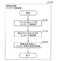
まず、イントラ予測部111は、ステップS225で使用した対象ブロック153の周辺の特徴点174を全て含む矩形領域である抽出領域175を指定するために必要な抽出範囲情報を符号化情報に付与する(S241)。例えば、抽出範囲情報は、抽出領域175の幅及び高さを確定するため情報であり、図12に示す幅171及び高さ172を示す情報を含む。
First, the
続いて、イントラ予測部111は、ステップS225で使用した特徴点(対応点)の数を示す個数情報を符号化情報に付与する(S242)。言い換えると、個数情報は、使用された特徴点の組に含まれる特徴点(対応点)の数を示す。
Subsequently, the
ステップS241の情報で指定される抽出領域175で抽出された特徴点174が全て利用される場合(S243でYes)、イントラ予測部111は、特徴点に関する詳細情報が存在することを示す詳細情報フラグをOFFに設定し、当該詳細情報フラグを符号化情報に付与する(S244)。
When all the feature points 174 extracted in the
一方、抽出領域175で抽出された特徴点のうち一つでも利用しない場合(S243でNo)、イントラ予測部111は、詳細情報フラグをONに設定し、当該詳細情報フラグを符号化情報に付与する(S245)。続いて、イントラ予測部111は、抽出領域175で抽出された特徴点174のうち、使用する特徴点を指定するための特徴点指定情報を特徴点の数分、符号化情報に付与する(S246)。例えば、この特徴点指定情報は、特徴点の座標を示す情報である。
On the other hand, when even one of the feature points extracted in the
なお、ステップS241と、ステップS242と、ステップS243〜S246の符号化処理の順序は、この順序である必要はなく、これらの順序は適宜入れ替えられてもよい。 The order of the coding processes of step S241, step S242, and steps S243 to S246 does not have to be this order, and these orders may be appropriately interchanged.
なお、ステップS241における抽出領域175の幅及び高さなどの指定は、符号ブロック単位で指定されてもよいし、画像単位又はシーケンス単位で指定されてもよい。また、抽出領域175の幅及び高さとして固定値が利用されてもよい。ブロック単位で、これらを変化させる場合、柔軟な範囲設定が可能となるので、予測画像の品質を向上できる。また、画像単位などでこれらの情報を指定する場合、符号化情報が少なくなるため符号化効率が向上する。
The width and height of the
また、抽出領域175の幅及び高さはそれぞれ別の値が指定されてもよいし、幅及び高さに同じ値が用いられてもよい。別の値を用いる場合、有効な特徴点を選択しやすくなることで予測画像の品質を向上できる。一方、同じ値を用いる場合、符号化に必要な情報が1つになるため符号量を削減できる。
Further, different values may be specified for the width and height of the
なお、ステップS241における抽出範囲情報は、幅及び高さに対応する画素の数を示してよいし、幅及び高さに対応する符号化済ブロックの個数を示してもよい。また、この場合、幅方向のブロックの個数及び高さ方向のブロックの個数の指定は、個別に行われてもよいし、幅方向のブロックの個数及び高さ方向のブロックの個数として同じ値が用いられてもよい。このようにブロックの個数を用いることで、幅などの距離情報を小さい値で表現できるため符号量を削減できる。 The extraction range information in step S241 may indicate the number of pixels corresponding to the width and height, or may indicate the number of coded blocks corresponding to the width and height. Further, in this case, the number of blocks in the width direction and the number of blocks in the height direction may be specified individually, or the same values are used for the number of blocks in the width direction and the number of blocks in the height direction. It may be used. By using the number of blocks in this way, distance information such as width can be expressed with a small value, so that the amount of code can be reduced.
次に、ステップS122のインター予測部115の処理の詳細を、図13のフローチャートを用いて説明する。
Next, the details of the processing of the
まず、インター予測部115は、既存の動画像符号化方式であるH.264/AVC方式又はH.265/HEVC方式で用いられている動き情報を利用したインター予測処理を行うことで予測画像を生成する(S261)。なお、以下では、この処理を、通常インター予測と呼ぶ。
First, the
次に、インター予測部115は、特徴点を利用したインター予測処理を行うことで予測画像を生成する(S262)。なお、以下では、この処理を、特徴点利用インター予測と呼ぶ。
Next, the
次に、インター予測部115は、ステップS261及びS262で得られたそれぞれの予測画像に対して、ステップS123と同様の処理を行うことで、符号化効率の高い手法を選択する(S263)。
Next, the
続いて、ステップS262の特徴点利用インター予測処理の詳細を、図14のフローチャートを用いて説明する。 Subsequently, the details of the feature point utilization inter-prediction process in step S262 will be described with reference to the flowchart of FIG.
まず、インター予測部115は、対象ブロック内の含まれる特徴点を利用したインター予測処理を行うことで予測画像を生成する(S281)。なお、以下では、この予測処理を、ブロック内モードと呼ぶ。
First, the
次に、インター予測部115は、対象ブロックの周辺の符号化済領域に存在する特徴点を利用したインター予測処理を行う(S282)。なお、以下では、この予測処理を、周辺ブロックモードと呼ぶ。
Next, the
次に、インター予測部115は、ステップS281及びS282で生成された予測画像に対して、ステップS123と同様の処理を行うことで、符号化効率の高い手法を選択する(S283)。
Next, the
続いて、ステップS281のブロック内モードでのインター予測処理の詳細を、図15のフローチャートを用いて説明する。 Subsequently, the details of the inter-prediction processing in the in-block mode of step S281 will be described with reference to the flowchart of FIG.
ステップS301、S302、S304及びS306の処理は、それぞれステップS181、S182、S184及びS186の処理と同様であるため、詳細は割愛する。 Since the processes of steps S301, S302, S304 and S306 are the same as the processes of steps S181, S182, S184 and S186, respectively, the details are omitted.
ステップS302で、対象ブロック内に特徴点が存在すると判定された場合(S302でYes)、インター予測部115は、ステップS112で得られた、1枚以上の参照画像から抽出された特徴点の中から、ステップS301で抽出された対象ブロック内の特徴点の対応点を探索する(S303)。
When it is determined in step S302 that a feature point exists in the target block (Yes in S302), the
ステップS303において対応点が存在する場合(S304でYes)、インター予測部115は、ステップS303で得られた結果を利用して予測画像を生成する(S305)。
When there is a corresponding point in step S303 (Yes in S304), the
図16は、この処理を説明するための図であり、予測処理の対象である対象ブロック153を含む対象画像150と、対象画像150とは異なるピクチャであり、既に符号化済みのピクチャである参照画像180とを示す。対象画像150は、既に符号化済みであり、復号ブロック129が生成されている符号化済領域151と、符号化が行われていない未符号化領域152とを含む。
FIG. 16 is a diagram for explaining this process, and is a reference which is a picture different from the
まず、インター予測部115は、ステップS185での予測対象領域155の設定手法と同様の手法で予測対象領域155を設定する。次に、インター予測部115は、ステップS303で発見した対応点182を中心として、ステップS185での参照領域157の設定手法と同様の手法にて、参照領域181を設定する。次に、インター予測部115は、ステップS185と同様の手法で、参照領域181から予測画像を生成する。つまり、インター予測部115は、参照領域181に含まれる、予測対象領域155における対象ブロック153の位置に対応する位置の画像である参照ブロック183の画素情報を用いて予測画像(予測ブロック)を生成する。
First, the
また、インター予測部115は、ステップS307において、ステップS187及びS227と同様の処理を行うことで、ステップS283においてステップS281の手法が選択されないようにする。
Further, the
続いて、ステップS282の周辺ブロックモードでのインター予測処理の詳細を、図17のフローチャートを用いて説明する。 Subsequently, the details of the inter-prediction processing in the peripheral block mode of step S282 will be described with reference to the flowchart of FIG.
ステップS321、S322、S324及びS326の処理は、それぞれS221、S222、S224及びS226の処理と同様であるため、詳細は割愛する。 Since the processing of steps S321, S322, S324 and S326 is the same as the processing of S221, S222, S224 and S226, respectively, the details are omitted.
ステップS322で、周辺の符号化済ブロックに特徴点が存在すると判定された場合(S322でYes)、インター予測部115は、ステップS321で抽出された1つ以上の特徴点のそれぞれに対して、ステップS112で得られた、1枚以上の参照画像から抽出された特徴点の中から対応点を探索する(S323)。ステップS323において対応点が存在する場合(S324でYes)、インター予測部115は、ステップS323で得られた対応点の結果を利用して予測画像を生成する(S325)。
When it is determined in step S322 that a feature point exists in the peripheral coded block (Yes in S322), the
図18は、この処理を説明するための図であり、予測処理の対象である対象ブロック153を含む対象画像150と、対象画像150とは異なるピクチャであり、既に符号化済みのピクチャである参照画像180とを示す。対象画像150は、既に符号化済みであり、復号ブロック129が生成されている符号化済領域151と、符号化が行われていない未符号化領域152とを含む。
FIG. 18 is a diagram for explaining this process, and is a reference which is a picture different from the
まず、インター予測部115は、ステップS225での予測対象領域165の設定手法と同様の手法で予測対象領域165を設定する。次に、インター予測部115は、ステップS323で発見した対応点192を用いて、ステップS225での参照領域167の設定手法と同様の手法にて、参照領域191を設定する。具体的には、インター予測部115は、予測対象領域165に含まれる特徴点164の対応点192を含む領域を参照領域191に設定する。
First, the
次に、インター予測部115は、ステップS225と同様の手法で、参照領域191から予測画像を生成する。具体的には、インター予測部115は、参照領域191に含まれる、予測対象領域165における対象ブロック153の位置に対応する位置の画像である参照ブロック193の画素情報を用いて予測画像(予測ブロック)を生成する。
Next, the
また、インター予測部115は、ステップS327において、ステップS187、S227及びS307と同様の処理を行うことで、ステップS283においてステップS282の手法が選択されないようにする。
Further, the
なお、ステップS321における対応点探索に必要な情報は、ステップS201でも述べたように、対応点を含む特徴点群(符号化済領域全体から抽出された特徴点)から、対応点を一意に決定できる指標でもよい。 As described in step S201, the information required for the corresponding point search in step S321 uniquely determines the corresponding point from the feature point group (feature points extracted from the entire encoded region) including the corresponding point. It may be an index that can be used.
(効果)
以上、本実施の形態によれば、局所特徴量に関する技術を応用することで、イントラ予測及びインター予測において、既存の手法と比較して少ない情報量で回転及び拡大といった高次な動き情報にも対応した予測画像を生成できる。
(effect)
As described above, according to the present embodiment, by applying the technique related to the local feature amount, in the intra-prediction and the inter-prediction, it is possible to obtain high-order motion information such as rotation and expansion with a smaller amount of information as compared with the existing method. The corresponding predicted image can be generated.
なお、本実施の形態では、ステップS101、S109及びS112で利用する特徴量抽出手法としてSIFTを例に説明を行っているが、使用できる特徴量及びその抽出手法はこれに限らない。他の局所特徴量に関連する技術である、ORB又はSURF(Speeded Up Robust Features)等が用いられてもよい。 In this embodiment, SIFT is described as an example of the feature amount extraction method used in steps S101, S109, and S112, but the feature amount that can be used and the extraction method thereof are not limited to this. ORB or SURF (Speeded Up Robust Features), which is a technique related to other local features, may be used.
また、特徴点の抽出手法と特徴量の算出手法とに異なる手法が用いられてもよい。具体的には、各手法には、処理量が少ないこと、又は、拡大縮小以外にもアフィン変換などにもロバストであるなど、それぞれ異なる性質がある。よって、符号化する動画像の種類などに応じて、利用する局所特徴量及びその抽出手法を変更することにより更に符号化効率を改善できる。 Further, different methods may be used for the feature point extraction method and the feature amount calculation method. Specifically, each method has different properties, such as a small amount of processing and robustness in affine transformation as well as scaling. Therefore, the coding efficiency can be further improved by changing the local feature amount to be used and the extraction method thereof according to the type of the moving image to be coded.
また、ステップS202からS205において、特徴点の詳細情報として座標以外に、特徴点の回転量及びスケール値などを挙げているが、詳細情報として利用できる情報はこれに限らない。 Further, in steps S202 to S205, in addition to the coordinates, the rotation amount and the scale value of the feature points are mentioned as the detailed information of the feature points, but the information that can be used as the detailed information is not limited to this.
また、ここで挙げた情報を必ず符号化する必要もない。例えば、特徴点の位置のみを抽出する手法の1つであるFASTにおいては、拡大縮小及び回転に対するロバスト性はない。よって、画像符号化装置100は、これらの情報を符号化する必要はない。このように、画像符号化装置100は、利用する特徴量に応じて符号化する情報を変更することで、予測画像の生成に必要な情報のみを符号化できる。
In addition, it is not always necessary to encode the information given here. For example, in FAST, which is one of the methods for extracting only the positions of feature points, there is no robustness to enlargement / reduction and rotation. Therefore, the
なお、ステップS181及びS301で抽出される特徴点は、1つだけでなく、複数であってもよい。この場合、画像符号化装置100は、複数の特徴点の情報を利用して予測画像を生成してもよい。これにより、生成される予測画像の品質が向上することで符号化効率が改善する。この処理は、ステップS161及びS281内において、画像符号化装置100が、各特徴点の対応点を探索し(S183及びS303)、複数の特徴点及び複数の対応点の関係を利用して予測画像を生成し(S185及びS305)、それぞれの特徴点に関する情報を符号化情報に付与する(S186及びS306)ことで実現できる。例えば、画像符号化装置100は、図10及び図18に示す場合と同様の処理により、複数の特徴点に対応する複数の対応点を探索し、当該複数の対応点を含む参照領域及び参照ブロックを決定できる。なお、複数の特徴点及び対応点の関係を利用した予測画像生成処理は、前述した手法に限らない。
The number of feature points extracted in steps S181 and S301 may be not limited to one but may be multiple. In this case, the
また、本実施の形態では、インター予測及びイントラ予測の両方で上記手法を用いる例を説明したが、インター予測のみ、又はイントラ予測のみで上記手法を用いてもよい。また、本実施の形態では、対象ブロック内の特徴点を用いる予測処理(インター予測又はイントラ予測)と、対象ブロック周辺の特徴点を用いる予測処理(インター予測又はイントラ予測)との両方を用いる例を説明したが、いずれか一方のみが用いられてもよい。 Further, in the present embodiment, an example in which the above method is used for both inter-prediction and intra-prediction has been described, but the above-mentioned method may be used only for inter-prediction or only for intra-prediction. Further, in the present embodiment, an example in which both a prediction process using feature points in the target block (inter-prediction or intra-prediction) and a prediction process using feature points around the target block (inter-prediction or intra-prediction) are used. However, only one of them may be used.
また、上記説明では、対応点は再構築画像(復号ブロック129又は復号画像131)に含まれる特徴点から選択されているが、入力画像121に含まれる特徴点から選択されてもよい。例えば、画像符号化装置100は、再構築画像内に対応点が存在しない場合に、入力画像121に含まれる特徴点から対応点を探索してもよい。
Further, in the above description, the corresponding points are selected from the feature points included in the reconstructed image (
(実施の形態2)
本実施の形態では、上記実施の形態1に係る画像符号化装置100及び画像符号化方法の変形例について説明する。
(Embodiment 2)
In this embodiment, a modification of the
なお、実施の形態1とステップS261の動き情報を利用した通常インター予測処理以外は同様であるため、ステップS261に関する説明以外は省略する。 Since the same is true except for the normal inter-prediction processing using the motion information of the first embodiment and step S261, the description other than the description of step S261 will be omitted.
ステップS261の動き情報を利用したインター予測処理の詳細を、図19のフローチャートを用いて説明する。 The details of the inter-prediction processing using the motion information in step S261 will be described with reference to the flowchart of FIG.
まず、インター予測部115は、動き情報の推定処理を行う(S341)。次に、インター予測部115は、ステップS341で得られた動き情報を利用して動き補償処理を行う(S342)。次に、インター予測部115は、符号化済みの時間的又は空間的な隣接ブロックの動き情報である予測動き情報と、ステップS342で決定した動き情報との差分である差分動き情報を生成する(S343)。
First, the
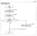
続いて、ステップS341の動き情報の推定処理の詳細を、図20のフローチャートを用いて説明する。 Subsequently, the details of the motion information estimation process in step S341 will be described with reference to the flowchart of FIG.
まず、インター予測部115は、ステップS101で入力画像から抽出された特徴点の中から、対象ブロックに含まれる特徴点を抽出する(S361)。次に、インター予測部115は、S101で得られた、インター予測で用いる参照画像が入力画像の時点で抽出された特徴点集合から、ステップS361で抽出された特徴点に対応する対応点を探索する(S362)。なお、この処理の詳細は、使用される特徴点が異なる点を除き、実施の形態1で説明した探索処理と同様である。
First, the
ステップS362において対応点の探索が成功した場合(S363でYes)、インター予測部115は、対応点の情報を用いて動き推定処理の初期値を設定する(S365)。この際、SIFT又はORBといった局所特徴量の対応点の関係からは、平行移動成分のみならず回転量及び拡大縮小に関する情報も取得できるため、それらに関する初期値も設定可能である。
When the search for the corresponding point is successful in step S362 (Yes in S363), the
一方、ステップS362において対応点の探索に失敗した場合(S363でNo)、インター予測部115は、動き推定処理の初期値に規定値を設定する(S364)。例えば、平行移動成分の規定値は0であり、拡大縮小のパラメータの規定値は1である。なお、インター予測部115は、低次元の情報に関して大まかに推定し、その結果を高次の動き情報の推定処理の初期値として利用してもよい。例えば、インター予測部115は、6次元のアフィン変換の動き情報を推定する際に、2次元の平行移動ベクトルの情報の推定結果を初期値に設定する。
On the other hand, when the search for the corresponding point fails in step S362 (No in S363), the
次に、インター予測部115は、ステップS364又はS365で設定された初期値を用いて動き推定処理を行う(S366)。
Next, the
(効果)
以上、本実施の形態によれば、特徴量の対応点の関係を活用することで、アフィン変換などを含む高次元の動き情報の推定処理に関して、効果的な初期値を設定できる。これにより動き情報推定処理の高速化及び推定結果による予測画像の品質向上を実現できる。
(effect)
As described above, according to the present embodiment, it is possible to set an effective initial value for the estimation processing of high-dimensional motion information including the affine transformation by utilizing the relationship of the corresponding points of the feature amount. As a result, it is possible to speed up the motion information estimation process and improve the quality of the predicted image based on the estimation result.
なお、ステップS362の処理においては、インター予測部115は、ステップS112で得られた、復号された参照画像から抽出された特徴点集合に対して、対応点の探索を行ってもよい。これにより、入力画像時に得られた特徴点集合情報を保存することが必要なくなり、処理中のメモリ量を削減できる。
In the process of step S362, the
また、本実施の形態では、上記実施の形態1の手法に加え、本実施の形態の処理を行う例を述べたが、本実施の形態に係る処理のみが行われてもよい。 Further, in the present embodiment, in addition to the method of the first embodiment, an example of performing the processing of the present embodiment has been described, but only the processing according to the present embodiment may be performed.
(実施の形態3)
本実施の形態では、上記画像符号化装置100により生成されたビットストリームを復号する画像復号装置の実施の形態の1つを説明する。
(Embodiment 3)
In this embodiment, one of the embodiments of the image decoding device that decodes the bit stream generated by the
図21は、本実施の形態に係る画像復号装置200の一例を示すブロック図である。画像復号装置200は、エントロピー復号部201、逆量子化部202、逆周波数変換部203、加算部204、特徴量抽出部205、イントラ予測部206、ループフィルタ207、フレームメモリ208、特徴量抽出部209、インター予測部210、切替部211を含む。
FIG. 21 is a block diagram showing an example of the
画像復号装置200は、入力されたビットストリーム221に対して復号処理を行うことで復号画像227を生成する。例えば、ビットストリーム221は、上記画像符号化装置100により生成される。なお、ビットストリーム221に含まれる各種情報の意味は、上述した実施の形態1と同様である。
The
図22は、本実施の形態における画像復号装置200による画像復号処理のフローチャートである。
FIG. 22 is a flowchart of the image decoding process by the
まず、エントロピー復号部201は、1以上のピクチャを含む静止画又は動画が符号化されることで得られたビットストリーム221から予測情報を復号する(S401)。続いて、エントロピー復号部201は、ビットストリーム221から係数ブロック222を復号する(S402)。
First, the
次に、逆量子化部202は、係数ブロック222を逆量子化することで係数ブロック223を生成する。逆周波数変換部203は、係数ブロック223を逆周波数変換することで差分ブロック224を復元する(S403)。
Next, the
次に、イントラ予測部206又はインター予測部210は、ステップS401で復号した予測情報と、復号ブロック225又は復号画像227を利用して、予測ブロック230を生成する(S404)。具体的には、イントラ予測部206は、イントラ予測処理により予測ブロック226を生成する。インター予測部210はインター予測処理により予測ブロック229を生成する。切替部211は、予測ブロック226及び229の一方を予測ブロック230として出力する。
Next, the
次に、加算部204は、ステップS403で得られた差分ブロック224と、ステップS404で得られた予測ブロック230とを加算することで復号ブロック225を生成する(S405)。この復号ブロック225は、イントラ予測部206によるイントラ予測処理に利用される。
Next, the
次に、特徴量抽出部205は、ステップS405までに復号された復号ブロック225の集合から特徴点及びその特徴点の特徴量を抽出する(S406)。ここで抽出された特徴点及び特徴量はイントラ予測の際に用いられる。なお、この処理の詳細は、上述したステップS109の処理と同様である。
Next, the feature
次に、画像復号装置200は、画像一枚分の復号ブロック225が復号されたかを判定する(S407)。画像一枚分の復号処理が終了していないと判定された場合(S407でNo)、画像復号装置200は、次のブロックの復号処理を行うためにステップS401からの処理を行う。
Next, the
一方、画像一枚分の復号ブロック225が復号されたと判定された場合(S407でYes)、ループフィルタ207は、復号された画像に対してフィルタ処理を行う(S408)。具体的には、ループフィルタ207は、1枚の画像に含まれる複数の復号ブロック225に、ブロック歪みによる画質劣化を緩和させるためのデブロッキングフィルタなどの画質改善のためのフィルタ処理を施すことで復号画像227を生成する。
On the other hand, when it is determined that the
また、フレームメモリ208は、復号画像227を格納する。この復号画像227は、インター予測部210によるインター予測処理に用いられる。
Further, the
次に、特徴量抽出部209は、復号画像227から特徴点及びその特徴点の特徴量を抽出する(S409)。なお、この処理の詳細は、上述したステップS111の処理と同様である。
Next, the feature
次に、画像復号装置200は、入力されたビットストリーム221に含まれる全ブロックが復号されたかを判定する(S410)。具体的には、画像復号装置200は、入力されたビットストリーム221が終了した場合に、全ブロックが復号されたと判定する。
Next, the
全ブロックが復号されたと判定されなった場合(S410でNo)、画像復号装置200は、次のブロックの復号処理を行うためにステップS401からの処理を行う。一方、全ブロックが復号されたと判定された場合(S410でYes)、画像復号装置200は、復号処理を終了する。
When it is determined that all the blocks have been decoded (No in S410), the
なお、ステップS403の逆量子化及び逆周波数変換処理は、それぞれを別処理として逐次行われてもよいし、一括して行われてもよい。なお、HEVCなどの現在主流の符号化規格では、逆量子化及び逆周波数変換処理が一括して行われる。また、復号側においても、これらの処理に、実施の形態1と同様に、スケーリング等の表現が用いられる場合がある。 The dequantization and reverse frequency conversion processes in step S403 may be sequentially performed as separate processes, or may be performed collectively. In the current mainstream coding standards such as HEVC, dequantization and reverse frequency conversion processing are collectively performed. Further, on the decoding side as well, expressions such as scaling may be used for these processes as in the first embodiment.
次に、ステップS401の予測情報復号処理の詳細を、図23のフローチャートを用いて説明する。 Next, the details of the prediction information decoding process in step S401 will be described with reference to the flowchart of FIG.
まず、画像復号装置200は、復号処理を行う対象のブロックである対象ブロックの予測手法がイントラ予測かインター予測かを判定する(S421)。
First, the
予測手法がイントラ予測と判定された場合(S421で「イントラ」)、画像復号装置200は、イントラ予測における予測モードが、復号済みの隣接ブロックの画素情報を利用する通常イントラ予測であるか、特徴点を利用する特徴点利用イントラ予測であるかを判定する(S422)。
When the prediction method is determined to be intra prediction (“intra” in S421), the
予測モードが、通常モードである場合(S422で「通常」)、画像復号装置200は、隣接ブロックの利用法に関する情報をビットストリーム221から復号する(S424)。ここで、隣接ブロックの利用法に関する情報とは、H.265/HEVC方式におけるイントラ予測方向などを示す情報である。
When the prediction mode is the normal mode (“normal” in S422), the
一方、予測モードが特徴点を利用するモードである場合(S422で「特徴点利用」)、画像復号装置200は、特徴点に関する情報である特徴点関連情報をビットストリーム221から復号する(S425)。
On the other hand, when the prediction mode is a mode in which the feature points are used (“feature point use” in S422), the
また、ステップS421で、予測モードがインター予測であると判定された場合(S421で「インター」)、画像復号装置200は、インター予測における予測モードが、動き情報を利用する通常インター予測であるか、特徴点を利用する特徴点利用インター予測であるかを判定する(S423)。
Further, when it is determined in step S421 that the prediction mode is inter-prediction (“inter” in S421), the
予測モードが通常イントラ予測である場合(S423で「通常」)、画像復号装置200は、ビットストリーム221から動き情報を復号する(S426)。ここで、動き情報とはH.265/HEVC方式を代表とする動画像符号化方式で利用されている平行移動ベクトル及び高次なアフィン変換行列などである。
When the prediction mode is normal intra-prediction (“normal” in S423), the
一方、予測モードが特徴点利用インター予測である場合(S423で「特徴点利用」)、画像復号装置200は、ビットストリーム221から特徴点に関する特徴点関連情報を復号する(S425)。
On the other hand, when the prediction mode is feature point utilization inter-prediction (“feature point utilization” in S423), the
なお、ステップS425の特徴点関連情報の復号処理は、イントラ予測の場合と、インター予測の場合とで、異なる処理部により実行されてもよい。これにより、イントラ予測処理及びインター予測処理に対して、同時に実行する場合に、ステップS425の処理を並列に処理できるので、処理を高速化できる。 The decoding process of the feature point related information in step S425 may be executed by different processing units depending on whether the intra prediction is performed or the inter prediction is performed. As a result, when the intra-prediction processing and the inter-prediction processing are executed at the same time, the processing of step S425 can be processed in parallel, so that the processing can be speeded up.
また、ステップS421〜S423の判定処理は、例えば、ビットストリーム221に含まれる情報に基づき行われる。具体的には、例えば、ビットストリーム221は、予測モードがイントラ予測であるか、インター予測であるかを示す情報を含む。また、ビットストリーム221は、予測モードが、通常イントラ予測であるか、特徴点利用イントラ予測であるかを示す情報、又は、予測モードが、通常インター予測であるか、特徴点利用インター予測であるかを示す情報を含む。
Further, the determination process of steps S421 to S423 is performed based on, for example, the information included in the
続いて、ステップS425の特徴点関連情報の復号処理の詳細を、図24のフローチャートを用いて説明する。 Subsequently, the details of the decoding process of the feature point-related information in step S425 will be described with reference to the flowchart of FIG. 24.
まず、画像復号装置200は、どのモードの特徴点関連情報が符号化されているかを判定する(S441)。対象ブロック内に存在する特徴点の情報であるブロック内モードの特徴量関連情報が符号化されていると判定された場合(S441で「ブロック内」)、画像復号装置200は、ビットストリーム221からブロック内モードの特徴量関連情報を復号する(S442)。
First, the
一方、対象ブロック周辺の復号済ブロックに含まれる特徴点の情報である周辺ブロックモードの特徴点関連情報が符号化されていると判定された場合(S441で「周辺ブロック」)、画像復号装置200は、ビットストリーム221から周辺ブロックモードの特徴点関連情報を復号する(S443)。
On the other hand, when it is determined that the feature point-related information in the peripheral block mode, which is the information of the feature points included in the decoded block around the target block, is encoded (“peripheral block” in S441), the
なお、ステップS441において、画像復号装置200は、ビットストリーム221に含まれる、ブロック内モード又は周辺ブロックモードを示すフラグを参照することで、上記判定処理を行う。このフラグはブロック単位で符号化されていてもよいし、画像単位又は動画像単位で符号化されていてもよい。このフラグがブロック単位で符号化される場合は、最適な符号化モードを選択可能となることで予測画像の品質が向上される。また、このフラグが画像単位などで符号化される場合は、フラグの数が減るため符号量が削減される。
In step S441, the
なお、ここでは、2つのモードが切り替えられる例を述べたが、ブロック内モード又は周辺ブロックモードのどちらか一方のモードが常に利用されてもよい。 Although the example in which the two modes are switched has been described here, either the in-block mode or the peripheral block mode may always be used.
続いて、ステップS442のブロック内モードの特徴点関連情報の復号処理の詳細を、図25のフローチャートを用いて説明する。ここで、ブロック内モードの特徴点関連情報は、対応点の情報である対応点情報と、対象ブロック内の特徴点の情報である特徴点情報とを含む。 Subsequently, the details of the decoding process of the feature point-related information in the in-block mode in step S442 will be described with reference to the flowchart of FIG. Here, the feature point-related information in the in-block mode includes the corresponding point information which is the corresponding point information and the feature point information which is the feature point information in the target block.
まず、画像復号装置200は、ビットストリーム221から、対象ブロック中の特徴点の対応点を決定するための対応点情報を復号する(S461)。具体的には、この対応点情報は対応点の座標を示す情報である。
First, the
次に、画像復号装置200は、ビットストリーム221が特徴点に関する詳細情報を含むことを示す詳細情報フラグがONであるかを判定する(S462)。なお、詳細情報フラグは、ビットストリーム221に含まれる。
Next, the
詳細情報フラグがOFFである場合(S462でNo)、画像復号装置200は、詳細情報に規定値を設定する(S463)。
When the detailed information flag is OFF (No in S462), the
一方、詳細情報フラグがONである場合(S462でYes)、画像復号装置200は、ビットストリーム221から詳細情報を復号する(S464)。
On the other hand, when the detailed information flag is ON (Yes in S462), the
ここで、詳細情報とは、符号化時において対象ブロック中に含まれていた特徴点の座標並びに特徴点のもつ回転量及びスケール値を示す情報である。 Here, the detailed information is information indicating the coordinates of the feature points included in the target block at the time of coding, the rotation amount of the feature points, and the scale value.
具体的には、特徴点の座標を示す詳細情報は、対象ブロックの中心から特徴点の位置を示すx及びy方向の2次元ベクトルである。また、回転量及びスケール値は、SIFTなどの局所特徴量抽出手法で算出された値である。これらの処理により、対象ブロック中の特徴点の座標と、その特徴点が持つ回転量及びスケール値などの情報と、対応点となる特徴点に関する情報とが復号される。 Specifically, the detailed information indicating the coordinates of the feature points is a two-dimensional vector in the x and y directions indicating the position of the feature points from the center of the target block. The rotation amount and the scale value are values calculated by a local feature amount extraction method such as SIFT. By these processes, the coordinates of the feature points in the target block, the information such as the rotation amount and the scale value of the feature points, and the information about the feature points to be the corresponding points are decoded.
なお、この特徴量の回転量及びスケール値は、対応点の回転量及びスケール値との相対値が符号化されていてもよい。これにより、特徴点と対応点とで回転量又はスケール値が同一の場合、符号化すべき情報が0となるため、符号化効率が向上する。また、算出値と相対値とのうちどちらを用いるかを示すフラグが符号化されていてもよい。これにより、各ブロックにおいて最適な符号化手法を選択することができるので、更に符号化効率が改善する。 The rotation amount and scale value of this feature amount may be encoded as a relative value to the rotation amount and scale value of the corresponding point. As a result, when the rotation amount or the scale value is the same at the feature point and the corresponding point, the information to be encoded becomes 0, so that the coding efficiency is improved. Further, a flag indicating which of the calculated value and the relative value is used may be encoded. As a result, the optimum coding method can be selected for each block, so that the coding efficiency is further improved.
また、ステップS463の規定値は、例えば、特徴点の座標においては対象ブロックの中心であり、回転量においては0度であり、スケール値においては1である。 Further, the specified value in step S463 is, for example, the center of the target block in the coordinates of the feature point, 0 degree in the rotation amount, and 1 in the scale value.
なお、この規定値は上記に限らない。例えばグローバルモーション情報から得られる回転角及び拡大率などが、それぞれ特徴点の回転量及びスケール値の設定に利用されてもよい。これにより、グローバルモーションに伴う画像の変形を利用することで、固定値を利用する場合よりも符号量を削減できる。 The specified value is not limited to the above. For example, the rotation angle and the enlargement ratio obtained from the global motion information may be used for setting the rotation amount and the scale value of the feature points, respectively. As a result, the amount of code can be reduced as compared with the case of using a fixed value by using the deformation of the image accompanying the global motion.
続いて、ステップS443の周辺ブロックモードの特徴点関連情報の復号処理の詳細を、図26のフローチャートを用いて説明する。 Subsequently, the details of the decoding process of the feature point-related information in the peripheral block mode in step S443 will be described with reference to the flowchart of FIG. 26.
まず、画像復号装置200は、特徴点を抽出する抽出領域を設定するために必要な情報である抽出範囲情報を復号する(S481)。次に、画像復号装置200は、予測画像の生成の際に使用する特徴点の数を示す個数情報を復号する(S482)。
First, the
次に、画像復号装置200は、特徴点の詳細情報が存在するかを示す詳細情報フラグがONであるかを判定する(S483)。
Next, the
詳細情報フラグがONである場合(S483でYes)、画像復号装置200は、予測画像生成時に利用する特徴点を識別するために必要な特徴点指定情報を復号する(S484)。例えば、この特徴点指定情報は、特徴点の座標を示す。
When the detailed information flag is ON (Yes in S483), the
これらの処理により、特徴点を抽出する対象である、対象ブロックの周辺の抽出領域と、予測画像の生成に使用する特徴点の数と、使用する特徴点を指定する情報とが復号される。 By these processes, the extraction area around the target block, which is the target for extracting the feature points, the number of feature points used to generate the predicted image, and the information specifying the feature points to be used are decoded.
なお、特徴点指定情報は、特徴点の座標情報である必要はなく、特徴点を一意に判別できる情報であればよい。例えば、特定点指定情報は、抽出領域内で抽出された特徴点をエッジの強度又は輝度成分の大きさなどでランク付けをした際の、順位を示してもよい。順位を用いた場合、1次元情報及び小さな数字で特徴量を指定できるため、符号量を削減できる。 The feature point designation information does not have to be the coordinate information of the feature points, and may be any information that can uniquely identify the feature points. For example, the specific point designation information may indicate the ranking when the feature points extracted in the extraction region are ranked according to the strength of the edge, the size of the luminance component, or the like. When the order is used, the feature amount can be specified by one-dimensional information and a small number, so that the code amount can be reduced.
次に、ステップS404の予測ブロック生成処理の詳細を、図27のフローチャートを用いて説明する。 Next, the details of the prediction block generation process in step S404 will be described with reference to the flowchart of FIG. 27.
まず、画像復号装置200は、予測ブロック生成処理にイントラ予測が用いられるかインター予測が用いられるかを判定する(S501)。なお、この判定は、ステップS421と同様に、ビットストリーム221に含まれる情報を用いて行われる。
First, the
イントラ予測が用いられると判定された場合(S501で「イントラ」)、画像復号装置200は、イントラ予測処理により予測ブロックを生成する(S502)。一方、インター予測が用いられると判定された場合(S501で「インター」)、画像復号装置200は、インター予測処理により予測ブロックを生成する(S503)。
When it is determined that the intra prediction is used (“intra” in S501), the
続いて、ステップS502のイントラ予測処理の詳細を、図28のフローチャートを用いて説明する。 Subsequently, the details of the intra prediction process in step S502 will be described with reference to the flowchart of FIG. 28.
まず、画像復号装置200は、イントラ予測における予測モードが、通常イントラ予測であるか特徴点利用イントラ予測であるかを判定する(S521)。なお、この判定は、ステップS422と同様に、ビットストリーム221に含まれる情報を用いて行われる。
First, the
予測モードが通常イントラ予測である場合(S521で「通常」)、画像復号装置200は、H.265/HEVC方式などで採用されているイントラ予測処理を行うことで予測画像を生成する(S522)。一方、予測モードが特徴点利用イントラ予測である場合(S521で「特徴点利用」)、画像復号装置200は、特徴点利用イントラ予測により予測画像を生成する(S523)。
When the prediction mode is normal intra-prediction (“normal” in S521), the
続いて、ステップS523の特徴点利用イントラ予測による予測画像生成処理の詳細を、図29のフローチャートを用いて説明する。 Subsequently, the details of the predicted image generation processing by the feature point utilization intra prediction in step S523 will be described with reference to the flowchart of FIG. 29.
まず、画像復号装置200は、特徴点の利用モードが、ブロック内モードであるか、周辺ブロックモードであるかを判定する(S541)。なお、この判定は、ステップS441と同様に、ビットストリーム221に含まれる情報を用いて行われる。
First, the
利用モードがブロック内モードである場合(S541で「ブロック内」)、画像復号装置200は、対象ブロック内の特徴点を利用したイントラ予測処理であるブロック内モードで予測画像を生成する(S542)。
When the usage mode is the in-block mode (“in-block” in S541), the
一方、利用モードが周辺ブロックモードである場合(S541で「周辺ブロック」)、画像復号装置200は、対象ブロックの周辺領域に含まれる特徴点情報を利用したイントラ予測処理である周辺ブロックモードで予測画像を生成する(S543)。
On the other hand, when the usage mode is the peripheral block mode (“peripheral block” in S541), the
続いて、ステップS542のブロック内モードの処理の詳細を、図30のフローチャートを用いて説明する。 Subsequently, the details of the processing of the in-block mode in step S542 will be described with reference to the flowchart of FIG.
まず、画像復号装置200は、ステップS442で復号された、ブロック内モードの特徴点関連情報を利用して、ステップS406で抽出された特徴点から、対応点を探索する(S561)。
First, the
具体的には、画像復号装置200は、ステップS406で抽出された複数の特徴点から、特徴点関連情報に含まれる、対応点を特定するための対応点情報(例えば、対応点の座標)を用いて、対応点を特定する。なお、対応点情報がインデックスである場合には、画像復号装置200は、符号化側と同様の手順により、複数の特徴点にインデックスを割り当て、対応点情報で示されるインデックスを有する特徴点を対応点に決定する。
Specifically, the
また、画像復号装置200は、対象ブロックに含まれる1以上の特徴点及びその特徴量を抽出し、抽出された特徴点から、特徴点関連情報に含まれる、特徴点を特定するための特徴点情報(例えば、特徴点の座標)を用いて、使用する特徴点を決定する。なお、特徴点情報が、回転量及びスケール値を示す場合には、画像復号装置200は、特徴点情報で示される回転量及びスケール値を有する特徴点を、使用する特徴点に決定する。
Further, the
次に、画像復号装置200は、ステップS561で得られた特徴点及び対応点を利用して、ステップS185と同様の処理を行うことで予測画像を生成する(S562)。
Next, the
続いて、ステップS543のブロック周辺モードの処理の詳細を、図31のフローチャートを用いて説明する。 Subsequently, the details of the processing of the block peripheral mode in step S543 will be described with reference to the flowchart of FIG.
まず、画像復号装置200は、ステップS481で復号された抽出範囲情報から決定される抽出領域に含まれる特徴点を、ステップS406で抽出された特徴点から抽出する。さらに、画像復号装置200は、抽出領域に含まれる特徴点から、ステップS482からS484で復号された個数情報及び特徴点指定情報で指定される特徴点を抽出する(S581)。
First, the
次に、画像復号装置200は、ステップS581で抽出された特徴点の対応点を、ステップS406で抽出された参照画像の特徴点群から探索する(S582)。つまり、画像復号装置200は、符号化側と同様に、特徴量を用いて、対象ブロックの周辺の特徴点の特徴量に類似する対応点を探索する。
Next, the
次に、画像復号装置200は、ステップS582で得られた対応点の情報を利用して、ステップS225の処理と同様の処理により、予測画像を生成する(S583)。
Next, the
次に、ステップS503のインター予測処理の詳細を、図32のフローチャートを用いて説明する。 Next, the details of the inter-prediction processing in step S503 will be described with reference to the flowchart of FIG.
まず、画像復号装置200は、インター予測の予測モードが通常インター予測であるか特徴点利用インター予測であるかを判定する(S601)。なお、この判定は、ステップS423と同様に、ビットストリーム221に含まれる情報を用いて行われる。
First, the
予測モードが通常インター予測である場合(S601で「通常」)、画像復号装置200は、H.265/HEVC方式で採用されているようなインター予測画像生成手法などの、動き情報を利用した予測画像生成処理を行うことで予測画像を生成する(S602)。この時、H.265/HEVCにおいては動き情報として平行移動ベクトルが使用されているが、アフィン変換行列又は射影変換行列などの高次元の情報を含む動き情報が利用されてもよい。
When the prediction mode is normal inter-prediction (“normal” in S601), the
一方、予測モードが特徴点利用インター予測である場合(S601で「特徴点利用」)、画像復号装置200は、特徴点利用インター予測により予測画像を生成する(S603)。
On the other hand, when the prediction mode is feature point utilization inter-prediction (“feature point utilization” in S601), the
続いて、ステップS603の特徴点利用インター予測による予測画像生成処理の詳細を、図33のフローチャートを用いて説明する。 Subsequently, the details of the prediction image generation processing by the feature point utilization inter-prediction in step S603 will be described with reference to the flowchart of FIG. 33.
まず、画像復号装置200は、特徴点の利用モードが、ブロック内モードであるか、周辺ブロックモードであるかを判定する(S621)。なお、この判定は、ステップS441と同様に、ビットストリーム221に含まれる情報を用いて行われる。
First, the
利用モードがブロック内モードである場合(S621で「ブロック内」)、画像復号装置200は、対象ブロック内の特徴点を利用したインター予測処理であるブロック内モードで予測画像を生成する(S622)。
When the usage mode is the in-block mode (“in-block” in S621), the
一方、利用モードが周辺ブロックモードである場合(S621で「周辺ブロック」)、画像復号装置200は、対象ブロックの周辺領域に含まれる特徴点情報を利用したインター予測処理である周辺ブロックモードで予測画像を生成する(S623)。
On the other hand, when the usage mode is the peripheral block mode (“peripheral block” in S621), the
続いて、ステップS622のブロック内モードの処理の詳細を、図34を用いて説明する。 Subsequently, the details of the processing of the in-block mode in step S622 will be described with reference to FIG. 34.
まず、画像復号装置200、ステップS442において復号された、ブロック内モードの特徴点関連情報を利用して、ステップS409で抽出された特徴点から、対応点を探索する(S641)。なお、この処理の詳細は、参照先が符号化済みの他のピクチャである点を除き、上述したステップS561と同様である。
First, the corresponding points are searched from the feature points extracted in step S409 by using the feature point-related information of the in-block mode decoded in the
次に、画像復号装置200は、ステップS641で得られた特徴点及び対応点を利用して、ステップS305と同様の処理を行うことで予測画像を生成する(S642)。
Next, the
続いて、ステップS623の周辺ブロックモードの処理の詳細を、図35を用いて説明する。 Subsequently, the details of the processing of the peripheral block mode in step S623 will be described with reference to FIG. 35.
まず、画像復号装置200は、ステップS481で復号された抽出範囲情報から決定される抽出領域に含まれる特徴点を、ステップS409で抽出された特徴点から抽出する。さらに、画像復号装置200は、抽出領域に含まれる特徴点から、ステップS482からS484で復号された個数情報及び特徴点指定情報で指定される特徴点を抽出する(S661)。
First, the
次に、画像復号装置200は、ステップS661で抽出された特徴点の対応点を、ステップS409で抽出された参照画像の特徴点群から対応点を探索する(S662)。
Next, the
次に、画像復号装置200は、ステップS662で得られた対応点の情報を利用して、ステップS325の処理と同様の処理により、予測画像を生成する(S663)。
Next, the
(効果)
以上、本実施の形態によれば、特徴点を利用したイントラ及びインター予測手法に関する情報が符号化されたビットストリームを復号できる。この構成によると、特徴点の利用を考慮したビットストリームを、特徴点の対応点を利用した予測画像生成処理を用いて復号することができ、より高画質な画像を再生できる。
(effect)
As described above, according to the present embodiment, it is possible to decode a bit stream in which information regarding an intra- and inter-prediction method using feature points is encoded. According to this configuration, a bit stream considering the use of feature points can be decoded by using a predictive image generation process using the corresponding points of the feature points, and a higher image quality image can be reproduced.
なお、実施の形態1で述べたように、局所特徴量として様々な特徴量を使用できる。他の局所特徴量に関連する技術である、ORB又はSURF等が用いられてもよい。また、特徴点の抽出手法と特徴量の算出手法とに異なる手法が用いられてもよい。 As described in the first embodiment, various feature amounts can be used as the local feature amounts. Other techniques related to local features, such as ORB or SURF, may be used. Further, different methods may be used for the feature point extraction method and the feature amount calculation method.
なお、実施の形態1で述べたように、ステップS561及びS641の処理で利用する対象ブロック内の特徴点は1つである必要はなく、複数の特徴点が使用されてもよい。この時、ステップS442における復号処理において、符号化している特徴点数に関する情報を復号する処理を追加し、ステップS461からS464の処理を符号化されている特徴点数だけ繰り返すことで、複数の特徴点を用いた処理を実現できる。このように複数の特徴点を利用することで、予測画像の精度が向上する。これにより残差成分が小さくなるので符号化効率が改善される。 As described in the first embodiment, the number of feature points in the target block used in the processes of steps S561 and S641 does not have to be one, and a plurality of feature points may be used. At this time, in the decoding process in step S442, a process of decoding information regarding the number of coded feature points is added, and the processes of steps S461 to S464 are repeated for the number of coded feature points to generate a plurality of feature points. The processing used can be realized. By using the plurality of feature points in this way, the accuracy of the predicted image is improved. As a result, the residual component becomes small, so that the coding efficiency is improved.
また、本実施の形態では、インター予測及びイントラ予測の両方で上記手法を用いる例を説明したが、インター予測のみ、又はイントラ予測のみで上記手法を用いてもよい。また、本実施の形態では、対象ブロック内の特徴点を用いる予測処理(インター予測又はイントラ予測)と、対象ブロック周辺の特徴点を用いる予測処理(インター予測又はイントラ予測)との両方を用いる例を説明したが、いずれか一方のみが用いられてもよい。 Further, in the present embodiment, an example in which the above method is used for both inter-prediction and intra-prediction has been described, but the above-mentioned method may be used only for inter-prediction or only for intra-prediction. Further, in the present embodiment, an example in which both a prediction process using feature points in the target block (inter-prediction or intra-prediction) and a prediction process using feature points around the target block (inter-prediction or intra-prediction) are used. However, only one of them may be used.
また、上記説明では、ブロック内モード時には、対応点を示す対応点情報が復号側に送信され、周辺ブロックモード時には、対応点情報が、復号側に送信されないが、周辺ブロックモード時においても、対応点情報が、復号側に送信されてもよい。この場合、画像復号装置200は、特徴量を用いた対応点の探索処理は行わず、対応点情報を用いて、複数の特徴点から対応点を特定する。
Further, in the above description, in the in-block mode, the corresponding point information indicating the corresponding point is transmitted to the decoding side, and in the peripheral block mode, the corresponding point information is not transmitted to the decoding side. The point information may be transmitted to the decoding side. In this case, the
また、ブロック内モード時に、対応点情報が復号側に送信されなくてもよい。この場合には、画像復号装置200は、符号化側と同様に、特徴量を用いた対応点の探索処理を行うことで、対応点を特定する。
Further, the corresponding point information may not be transmitted to the decoding side in the in-block mode. In this case, the
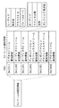
以上のように、実施の形態に係る画像符号化方法及び画像復号方法は、図36に示す予測画像生成方法を含む。 As described above, the image coding method and the image decoding method according to the embodiment include the predicted image generation method shown in FIG. 36.
本実施の形態に係る予測画像生成装置は、対象ブロックの予測画像を生成する。まず、予測画像生成装置は、再構築画像に含まれる、各々が局所特徴量を有する複数の第1特徴点を抽出する(S701)。ここで再構築画像とは、イントラ予測においては、対象ブロックを含む対象ピクチャに含まれる符号化又は復号済みのブロックであり、インター予測において、対象ピクチャと異なる符号化又は復号済みのピクチャである。 The predictive image generation device according to the present embodiment generates a predictive image of the target block. First, the predictive image generation device extracts a plurality of first feature points, each of which has a local feature amount, included in the reconstructed image (S701). Here, the reconstructed image is a coded or decoded block included in the target picture including the target block in the intra prediction, and is a coded or decoded picture different from the target picture in the inter prediction.
また、予測画像生成装置を備える画像符号化装置では、さらに、対象ブロックに対応する複数の第3特徴点が抽出される。具体的には、第3特徴点は、上記ブロック内モードにおいては、対象ブロックに含まれる特徴点であり、上記周辺ブロックモードにおいては、対象ブロックに含まれない、対象ブロック周辺の特徴点である。 Further, in the image coding device including the predictive image generation device, a plurality of third feature points corresponding to the target block are further extracted. Specifically, the third feature point is a feature point included in the target block in the in-block mode, and is a feature point around the target block that is not included in the target block in the peripheral block mode. ..
次に、予測画像生成装置は、複数の第1特徴点から、対象ブロックに対応する第2特徴点の局所特徴量に類似する局所特徴量を有し、第2特徴点との関係が、非平行移動成分を含む情報で表現される対応点を探索する(S702)。具体的には、第2特徴点は、上記ブロック内モードにおいては、対象ブロックに含まれる特徴点であり、上記周辺ブロックモードにおいては、対象ブロックに含まれない、対象ブロック周辺の特徴点である。 Next, the predictive image generator has a local feature amount similar to the local feature amount of the second feature point corresponding to the target block from the plurality of first feature points, and the relationship with the second feature point is not. A corresponding point represented by information including a translation component is searched for (S702). Specifically, the second feature point is a feature point included in the target block in the in-block mode, and is a feature point in the vicinity of the target block that is not included in the target block in the peripheral block mode. ..
具体的には、画像符号化装置では、対象ブロックに対応する複数の第3特徴点から第2特徴点が選択される。画像符号化装置は、局所特徴量の類似性を用いて、複数の第1特徴点から、第2特徴点に局所特徴量に類似する局所特徴量を有する対応点を探索する。また、画像符号化装置は、複数の第3特徴点のうち第2特徴点を特定するための特徴点情報を符号化し、当該特徴点情報を画像復号装置へ送信する。また、画像符号化装置は、複数の第1特徴点のうち対応点を特定するための対応点情報を符号化してもよい。 Specifically, in the image coding apparatus, the second feature point is selected from the plurality of third feature points corresponding to the target block. The image coding apparatus searches for a corresponding point having a local feature amount similar to the local feature amount in the second feature point from a plurality of first feature points by using the similarity of the local feature amount. Further, the image coding device encodes the feature point information for specifying the second feature point among the plurality of third feature points, and transmits the feature point information to the image decoding device. Further, the image coding apparatus may encode the corresponding point information for specifying the corresponding point among the plurality of first feature points.
一方、画像復号装置では、上記特徴点情報が復号される。画像復号装置は、対象ブロックに対応する複数の第3特徴点を抽出し、特徴点情報を用いて、複数の第3特徴点から第2特徴点を選択する。また、画像復号装置は、符号化側と同様に、局所特徴量の類似性を用いて、複数の第1特徴点から、第2特徴点に局所特徴量に類似する局所特徴量を有する対応点を探索する。または、対応点情報がビットストリームに含まる場合には、画像復号装置は、当該対応点情報を復号し、当該対応点復号情報を用いて複数の第1特徴点から対応点を探索する。 On the other hand, in the image decoding device, the feature point information is decoded. The image decoding device extracts a plurality of third feature points corresponding to the target block, and uses the feature point information to select a second feature point from the plurality of third feature points. Further, the image decoding device uses the similarity of the local feature amount as in the coding side to have a corresponding point having a local feature amount similar to the local feature amount from the plurality of first feature points to the second feature point. To explore. Alternatively, when the corresponding point information is included in the bit stream, the image decoding device decodes the corresponding point information and searches for the corresponding point from a plurality of first feature points using the corresponding point decoding information.
次に、予測画像生成装置は、第2特徴点と対応点との関係に基づき、再構築画像から予測画像を生成する(S703)。具体的には、予測画像生成装置は、再構築画像内の対応点の周辺の画素値を用いて、上記関係に基づき予測画像を生成する。例えば、上記ブロック内モードでは、予測画像生成装置は、再構築画像内の対応点を含む領域の画素値を用いて予測画像を生成する。また、上記周辺ブロックモードでは、予測画像生成装置は、再構築画像内の対応点を含まない領域の画素値を用いて予測画像を生成する。 Next, the prediction image generation device generates a prediction image from the reconstructed image based on the relationship between the second feature point and the corresponding point (S703). Specifically, the predictive image generation device generates a predictive image based on the above relationship by using the pixel values around the corresponding points in the reconstructed image. For example, in the in-block mode, the predictive image generator generates a predictive image using the pixel values of the region including the corresponding points in the reconstructed image. Further, in the peripheral block mode, the predictive image generation device generates a predictive image using the pixel values in the region of the reconstructed image that does not include the corresponding point.
なお、画像符号化装置は、対応点の周辺の画素値を用いて予測画像を生成するのではなく、実施の形態2で説明したように、第2特徴点と対応点との関係に基づき、動き推定処理の初期値を設定し、当該初期値を用いて、動き推定処理を行うことで予測画像を生成してもよい。 The image coding device does not generate a predicted image using the pixel values around the corresponding points, but is based on the relationship between the second feature point and the corresponding points, as described in the second embodiment. A predicted image may be generated by setting an initial value of the motion estimation process and performing the motion estimation process using the initial value.
また、画像符号化装置では、さらに、生成された予測画像を用いて対象ブロックが符号化され、画像復号装置では、さらに、生成された予測画像を用いて対象ブロックが復号される。 Further, the image coding device further encodes the target block using the generated predicted image, and the image decoding device further decodes the target block using the generated predicted image.
以上、実施の形態に係る予測画像生成方法、画像符号化方法に及び画像復号方法ついて説明したが、本発明は、この実施の形態に限定されるものではない。 Although the predicted image generation method, the image coding method, and the image decoding method according to the embodiment have been described above, the present invention is not limited to this embodiment.
また、上記実施の形態に係る予測画像生成装置、画像符号化装置及び画像復号装置に含まれる各処理部は典型的には集積回路であるLSIとして実現される。これらは個別に1チップ化されてもよいし、一部又は全てを含むように1チップ化されてもよい。 Further, each processing unit included in the predictive image generation device, the image coding device, and the image decoding device according to the above embodiment is typically realized as an LSI which is an integrated circuit. These may be individually integrated into one chip, or may be integrated into one chip so as to include a part or all of them.
また、集積回路化はLSIに限るものではなく、専用回路又は汎用プロセッサで実現してもよい。LSI製造後にプログラムすることが可能なFPGA(Field Programmable Gate Array)、又はLSI内部の回路セルの接続や設定を再構成可能なリコンフィギュラブル・プロセッサを利用してもよい。 Further, the integrated circuit is not limited to the LSI, and may be realized by a dedicated circuit or a general-purpose processor. An FPGA (Field Programmable Gate Array) that can be programmed after the LSI is manufactured, or a reconfigurable processor that can reconfigure the connection and settings of circuit cells inside the LSI may be used.
上記各実施の形態において、各構成要素は、専用のハードウェアで構成されるか、各構成要素に適したソフトウェアプログラムを実行することによって実現されてもよい。各構成要素は、CPU又はプロセッサなどのプログラム実行部が、ハードディスク又は半導体メモリなどの記録媒体に記録されたソフトウェアプログラムを読み出して実行することによって実現されてもよい。 In each of the above embodiments, each component may be configured with dedicated hardware or may be realized by executing a software program suitable for each component. Each component may be realized by a program execution unit such as a CPU or a processor reading and executing a software program recorded on a recording medium such as a hard disk or a semiconductor memory.
言い換えると、予測画像生成装置、画像符号化装置及び画像復号装置は、処理回路(processing circuitry)と、当該処理回路に電気的に接続された(当該制御回路からアクセス可能な)記憶装置(storage)とを備える。処理回路は、専用のハードウェア及びプログラム実行部の少なくとも一方を含む。また、記憶装置は、処理回路がプログラム実行部を含む場合には、当該プログラム実行部により実行されるソフトウェアプログラムを記憶する。処理回路は、記憶装置を用いて、上記実施の形態に係る予測画像生成方法、符号化方法又は復号方法を実行する。 In other words, the predictive image generator, the image coding device, and the image decoding device are a processing circuit (processing circuit) and a storage device (accessible from the control circuit) electrically connected to the processing circuit (accessible from the control circuit). And. The processing circuit includes at least one of dedicated hardware and a program execution unit. Further, when the processing circuit includes a program execution unit, the storage device stores the software program executed by the program execution unit. The processing circuit uses the storage device to execute the predicted image generation method, the coding method, or the decoding method according to the above embodiment.
さらに、本発明は上記ソフトウェアプログラムであってもよいし、上記プログラムが記録された非一時的なコンピュータ読み取り可能な記録媒体であってもよい。また、上記プログラムは、インターネット等の伝送媒体を介して流通させることができるのは言うまでもない。 Further, the present invention may be the software program or a non-temporary computer-readable recording medium in which the program is recorded. Needless to say, the above program can be distributed via a transmission medium such as the Internet.
また、上記で用いた数字は、全て本発明を具体的に説明するために例示するものであり、本発明は例示された数字に制限されない。 In addition, the numbers used above are all exemplified for the purpose of specifically explaining the present invention, and the present invention is not limited to the exemplified numbers.
また、ブロック図における機能ブロックの分割は一例であり、複数の機能ブロックを一つの機能ブロックとして実現したり、一つの機能ブロックを複数に分割したり、一部の機能を他の機能ブロックに移してもよい。また、類似する機能を有する複数の機能ブロックの機能を単一のハードウェア又はソフトウェアが並列又は時分割に処理してもよい。 In addition, the division of functional blocks in the block diagram is an example, and multiple functional blocks can be realized as one functional block, one functional block can be divided into multiple, and some functions can be transferred to other functional blocks. You may. Further, the functions of a plurality of functional blocks having similar functions may be processed by a single hardware or software in parallel or in a time division manner.
また、上記の予測画像生成方法、符号化方法又は復号方法に含まれるステップが実行される順序は、本発明を具体的に説明するために例示するためのものであり、上記以外の順序であってもよい。また、上記ステップの一部が、他のステップと同時(並列)に実行されてもよい。 Further, the order in which the steps included in the above-mentioned predicted image generation method, coding method, or decoding method are executed is for exemplifying the present invention in a concrete manner, and is in an order other than the above. You may. Further, a part of the above steps may be executed simultaneously with other steps (parallel).
以上、本発明の一つ又は複数の態様に係る予測画像生成装置、符号化装置及び復号装置について、実施の形態に基づいて説明したが、本発明は、この実施の形態に限定されるものではない。本発明の趣旨を逸脱しない限り、当業者が思いつく各種変形を本実施の形態に施したものや、異なる実施の形態における構成要素を組み合わせて構築される形態も、本発明の一つ又は複数の態様の範囲内に含まれてもよい。 Although the predictive image generation device, the coding device, and the decoding device according to one or more aspects of the present invention have been described above based on the embodiments, the present invention is not limited to the present embodiments. No. As long as it does not deviate from the gist of the present invention, one or more of the present embodiments may be modified by those skilled in the art, or may be constructed by combining components in different embodiments. It may be included within the scope of the embodiment.
(実施の形態4)
上記各実施の形態で示した動画像符号化方法(画像符号化方法)または動画像復号化方法(画像復号方法)の構成を実現するためのプログラムを記憶メディアに記録することにより、上記各実施の形態で示した処理を独立したコンピュータシステムにおいて簡単に実施することが可能となる。記憶メディアは、磁気ディスク、光ディスク、光磁気ディスク、ICカード、半導体メモリ等、プログラムを記録できるものであればよい。
(Embodiment 4)
Each of the above embodiments is carried out by recording a program for realizing the configuration of the moving image coding method (image coding method) or the moving image decoding method (image decoding method) shown in each of the above embodiments on a storage medium. It becomes possible to easily carry out the processing shown in the above embodiment in an independent computer system. The storage medium may be a magnetic disk, an optical disk, a magneto-optical disk, an IC card, a semiconductor memory, or the like, as long as it can record a program.
さらにここで、上記各実施の形態で示した動画像符号化方法(画像符号化方法)や動画像復号化方法(画像復号方法)の応用例とそれを用いたシステムを説明する。当該システムは、画像符号化方法を用いた画像符号化装置、及び画像復号方法を用いた画像復号装置からなる画像符号化復号装置を有することを特徴とする。システムにおける他の構成について、場合に応じて適切に変更することができる。 Further, an application example of the moving image coding method (image coding method) and the moving image decoding method (image decoding method) shown in each of the above embodiments and a system using the same will be described here. The system is characterized by having an image coding / decoding device including an image coding device using an image coding method and an image decoding device using an image decoding method. Other configurations in the system can be changed appropriately as the case may be.
図37は、コンテンツ配信サービスを実現するコンテンツ供給システムex100の全体構成を示す図である。通信サービスの提供エリアを所望の大きさに分割し、各セル内にそれぞれ固定無線局である基地局ex106、ex107、ex108、ex109、ex110が設置されている。 FIG. 37 is a diagram showing an overall configuration of a content supply system ex100 that realizes a content distribution service. The area for providing the communication service is divided into desired sizes, and base stations ex106, ex107, ex108, ex109, and ex110, which are fixed radio stations, are installed in each cell.
このコンテンツ供給システムex100は、インターネットex101にインターネットサービスプロバイダex102および電話網ex104、および基地局ex106からex110を介して、コンピュータex111、PDA(Personal Digital Assistant)ex112、カメラex113、携帯電話ex114、ゲーム機ex115などの各機器が接続される。 This content supply system ex100 has a computer ex111, a PDA (Personal Digital Assistant) ex112, a camera ex113, a mobile phone ex114, and a game machine ex115 via the Internet service provider ex102 and the telephone network ex104, and the base station ex106 to the Internet ex101. Each device such as is connected.
しかし、コンテンツ供給システムex100は図37のような構成に限定されず、いずれかの要素を組合せて接続するようにしてもよい。また、固定無線局である基地局ex106からex110を介さずに、各機器が電話網ex104に直接接続されてもよい。また、各機器が近距離無線等を介して直接相互に接続されていてもよい。 However, the content supply system ex100 is not limited to the configuration as shown in FIG. 37, and any element may be combined and connected. Further, each device may be directly connected to the telephone network ex104 from the base station ex106, which is a fixed radio station, without going through the ex110. Further, the devices may be directly connected to each other via short-range wireless communication or the like.
カメラex113はデジタルビデオカメラ等の動画撮影が可能な機器であり、カメラex116はデジタルカメラ等の静止画撮影、動画撮影が可能な機器である。また、携帯電話ex114は、GSM(登録商標)(Global System for Mobile Communications)方式、CDMA(Code Division Multiple Access)方式、W−CDMA(Wideband-Code Division Multiple Access)方式、若しくはLTE(Long Term Evolution)方式、HSPA(High Speed Packet Access)の携帯電話機、またはPHS(Personal Handyphone System)等であり、いずれでも構わない。 The camera ex113 is a device capable of shooting moving images such as a digital video camera, and the camera ex116 is a device capable of shooting still images and shooting moving images such as a digital camera. The mobile phone ex114 is a GSM (registered trademark) (Global System for Mobile Communications) system, a CDMA (Code Division Multiple Access) system, a W-CDMA (Wideband-Code Division Multiple Access) system, or an LTE (Long Term Evolution) system. It may be a method, an HSPA (High Speed Packet Access) mobile phone, a PHS (Personal Handyphone System), or the like.
コンテンツ供給システムex100では、カメラex113等が基地局ex109、電話網ex104を通じてストリーミングサーバex103に接続されることで、ライブ配信等が可能になる。ライブ配信では、ユーザがカメラex113を用いて撮影するコンテンツ(例えば、音楽ライブの映像等)に対して上記各実施の形態で説明したように符号化処理を行い(即ち、本発明の一態様に係る画像符号化装置として機能する)、ストリーミングサーバex103に送信する。一方、ストリーミングサーバex103は要求のあったクライアントに対して送信されたコンテンツデータをストリーム配信する。クライアントとしては、上記符号化処理されたデータを復号化することが可能な、コンピュータex111、PDAex112、カメラex113、携帯電話ex114、ゲーム機ex115等がある。配信されたデータを受信した各機器では、受信したデータを復号化処理して再生する(即ち、本発明の一態様に係る画像復号装置として機能する)。 In the content supply system ex100, the camera ex113 and the like are connected to the streaming server ex103 through the base station ex109 and the telephone network ex104, so that live distribution and the like become possible. In the live distribution, the content (for example, a live music image or the like) taken by the user using the camera ex113 is encoded as described in each of the above embodiments (that is, according to one aspect of the present invention). (Functions as the image encoding device), and transmits to the streaming server ex103. On the other hand, the streaming server ex103 streams the content data transmitted to the requested client. Examples of the client include a computer ex111, a PDAex112, a camera ex113, a mobile phone ex114, a game machine ex115, and the like, which can decode the coded data. Each device that has received the delivered data decodes and reproduces the received data (that is, functions as an image decoding device according to one aspect of the present invention).
なお、撮影したデータの符号化処理はカメラex113で行っても、データの送信処理をするストリーミングサーバex103で行ってもよいし、互いに分担して行ってもよい。同様に配信されたデータの復号化処理はクライアントで行っても、ストリーミングサーバex103で行ってもよいし、互いに分担して行ってもよい。また、カメラex113に限らず、カメラex116で撮影した静止画像および/または動画像データを、コンピュータex111を介してストリーミングサーバex103に送信してもよい。この場合の符号化処理はカメラex116、コンピュータex111、ストリーミングサーバex103のいずれで行ってもよいし、互いに分担して行ってもよい。 The captured data may be encoded by the camera ex113, by the streaming server ex103 that performs the data transmission processing, or may be shared with each other. Similarly, the decryption process of the delivered data may be performed by the client, the streaming server ex103, or may be shared with each other. Further, not only the camera ex113 but also the still image and / or the moving image data taken by the camera ex116 may be transmitted to the streaming server ex103 via the computer ex111. The coding process in this case may be performed by any of the camera ex116, the computer ex111, and the streaming server ex103, or may be shared with each other.
また、これら符号化・復号化処理は、一般的にコンピュータex111や各機器が有するLSIex500において処理する。LSIex500は、ワンチップであっても複数チップからなる構成であってもよい。なお、動画像符号化・復号化用のソフトウェアをコンピュータex111等で読み取り可能な何らかの記録メディア(CD−ROM、フレキシブルディスク、ハードディスクなど)に組み込み、そのソフトウェアを用いて符号化・復号化処理を行ってもよい。さらに、携帯電話ex114がカメラ付きである場合には、そのカメラで取得した動画データを送信してもよい。このときの動画データは携帯電話ex114が有するLSIex500で符号化処理されたデータである。 Further, these coding / decoding processes are generally performed by the computer ex111 or the LSI ex500 of each device. The LSI ex500 may be one chip or may be composed of a plurality of chips. In addition, software for video coding / decoding is incorporated into some recording medium (CD-ROM, flexible disk, hard disk, etc.) that can be read by a computer ex111 or the like, and the coding / decoding processing is performed using the software. You may. Further, when the mobile phone ex114 is equipped with a camera, the moving image data acquired by the camera may be transmitted. The moving image data at this time is the data encoded by the LSI ex500 possessed by the mobile phone ex114.
また、ストリーミングサーバex103は複数のサーバや複数のコンピュータであって、データを分散して処理したり記録したり配信するものであってもよい。 Further, the streaming server ex103 may be a plurality of servers or a plurality of computers, and may be one that distributes, processes, records, and distributes data.
以上のようにして、コンテンツ供給システムex100では、符号化されたデータをクライアントが受信して再生することができる。このようにコンテンツ供給システムex100では、ユーザが送信した情報をリアルタイムでクライアントが受信して復号化し、再生することができ、特別な権利や設備を有さないユーザでも個人放送を実現できる。 As described above, in the content supply system ex100, the client can receive and reproduce the encoded data. In this way, in the content supply system ex100, the client can receive, decode, and reproduce the information transmitted by the user in real time, and even a user who does not have special rights or equipment can realize personal broadcasting.
なお、コンテンツ供給システムex100の例に限らず、図38に示すように、デジタル放送用システムex200にも、上記各実施の形態の少なくとも動画像符号化装置(画像符号化装置)または動画像復号化装置(画像復号装置)のいずれかを組み込むことができる。具体的には、放送局ex201では映像データに音楽データなどが多重化された多重化データが電波を介して通信または衛星ex202に伝送される。この映像データは上記各実施の形態で説明した動画像符号化方法により符号化されたデータである(即ち、本発明の一態様に係る画像符号化装置によって符号化されたデータである)。これを受けた放送衛星ex202は、放送用の電波を発信し、この電波を衛星放送の受信が可能な家庭のアンテナex204が受信する。受信した多重化データを、テレビ(受信機)ex300またはセットトップボックス(STB)ex217等の装置が復号化して再生する(即ち、本発明の一態様に係る画像復号装置として機能する)。 Not limited to the example of the content supply system ex100, as shown in FIG. 38, the digital broadcasting system ex200 also has at least a moving image coding device (image coding device) or a moving image decoding according to each of the above embodiments. Any of the devices (image decoding devices) can be incorporated. Specifically, at the broadcasting station ex201, the multiplexed data in which music data or the like is multiplexed with the video data is transmitted via radio waves or to the satellite ex202. This video data is data encoded by the moving image coding method described in each of the above embodiments (that is, data encoded by the image coding apparatus according to one aspect of the present invention). In response to this, the broadcasting satellite ex202 transmits radio waves for broadcasting, and the radio waves are received by the home antenna ex204 capable of receiving satellite broadcasting. A device such as a television (receiver) ex300 or a set-top box (STB) ex217 decodes and reproduces the received multiplexed data (that is, functions as an image decoding device according to one aspect of the present invention).
また、DVD、BD等の記録メディアex215に記録した多重化データを読み取り復号化する、または記録メディアex215に映像信号を符号化し、さらに場合によっては音楽信号と多重化して書き込むリーダ/レコーダex218にも上記各実施の形態で示した動画像復号化装置または動画像符号化装置を実装することが可能である。この場合、再生された映像信号はモニタex219に表示され、多重化データが記録された記録メディアex215により他の装置やシステムにおいて映像信号を再生することができる。また、ケーブルテレビ用のケーブルex203または衛星/地上波放送のアンテナex204に接続されたセットトップボックスex217内に動画像復号化装置を実装し、これをテレビのモニタex219で表示してもよい。このときセットトップボックスではなく、テレビ内に動画像復号化装置を組み込んでもよい。 Further, the reader / recorder ex218 also reads and decodes the multiplexed data recorded on the recording medium ex215 such as a DVD or BD, or encodes the video signal on the recording medium ex215 and, in some cases, multiplexes and writes the video signal to the music signal. It is possible to implement the moving image decoding device or the moving image coding device shown in each of the above embodiments. In this case, the reproduced video signal is displayed on the monitor ex219, and the video signal can be reproduced in another device or system by the recording medium ex215 in which the multiplexed data is recorded. Further, a moving image decoding device may be mounted in a set-top box ex217 connected to a cable ex203 for cable TV or an antenna ex204 for satellite / terrestrial broadcasting, and this may be displayed on a TV monitor ex219. At this time, the moving image decoding device may be incorporated in the television instead of the set-top box.
図39は、上記各実施の形態で説明した動画像復号化方法および動画像符号化方法を用いたテレビ(受信機)ex300を示す図である。テレビex300は、上記放送を受信するアンテナex204またはケーブルex203等を介して映像データに音声データが多重化された多重化データを取得、または出力するチューナex301と、受信した多重化データを復調する、または外部に送信する多重化データに変調する変調/復調部ex302と、復調した多重化データを映像データと、音声データとに分離する、または信号処理部ex306で符号化された映像データ、音声データを多重化する多重/分離部ex303を備える。 FIG. 39 is a diagram showing a television (receiver) ex300 using the moving image decoding method and the moving image coding method described in each of the above embodiments. The TV ex300 acquires or outputs multiplexed data in which audio data is multiplexed with video data via an antenna ex204 or a cable ex203 that receives the above broadcast, and a tuner ex301 that outputs or demolishes the received multiplexed data. Alternatively, the modulation / demodulation unit ex302 that modulates the multiplexed data to be transmitted to the outside, and the video data and audio data that separate the demodulated multiplexed data into video data and audio data, or are encoded by the signal processing unit ex306. It is provided with a multiplexing / separation unit ex303 for multiplexing.
また、テレビex300は、音声データ、映像データそれぞれを復号化する、またはそれぞれの情報を符号化する音声信号処理部ex304、映像信号処理部ex305(本発明の一態様に係る画像符号化装置または画像復号装置として機能する)を有する信号処理部ex306と、復号化した音声信号を出力するスピーカex307、復号化した映像信号を表示するディスプレイ等の表示部ex308を有する出力部ex309とを有する。さらに、テレビex300は、ユーザ操作の入力を受け付ける操作入力部ex312等を有するインタフェース部ex317を有する。さらに、テレビex300は、各部を統括的に制御する制御部ex310、各部に電力を供給する電源回路部ex311を有する。インタフェース部ex317は、操作入力部ex312以外に、リーダ/レコーダex218等の外部機器と接続されるブリッジex313、SDカード等の記録メディアex216を装着可能とするためのスロット部ex314、ハードディスク等の外部記録メディアと接続するためのドライバex315、電話網と接続するモデムex316等を有していてもよい。なお記録メディアex216は、格納する不揮発性/揮発性の半導体メモリ素子により電気的に情報の記録を可能としたものである。テレビex300の各部は同期バスを介して互いに接続されている。 Further, the television ex300 has an audio signal processing unit ex304 and a video signal processing unit ex305 (an image coding device or an image according to one aspect of the present invention) that decodes each of the audio data and the video data or encodes the respective information. It has a signal processing unit ex306 having a function as a decoding device), a speaker ex307 for outputting a decoded audio signal, and an output unit ex309 having a display unit ex308 such as a display for displaying the decoded video signal. Further, the television ex300 has an interface unit ex317 having an operation input unit ex312 or the like for receiving input of a user operation. Further, the television ex300 has a control unit ex310 that controls each unit in an integrated manner, and a power supply circuit unit ex311 that supplies electric power to each unit. In addition to the operation input unit ex312, the interface unit ex317 has a bridge ex313 connected to an external device such as a reader / recorder ex218, a slot unit ex314 for mounting a recording medium ex216 such as an SD card, and an external recording such as a hard disk. It may have a driver ex315 for connecting to media, a modem ex316 for connecting to a telephone network, and the like. The recording medium ex216 is capable of electrically recording information by a stored non-volatile / volatile semiconductor memory element. Each part of the television ex300 is connected to each other via a synchronization bus.
まず、テレビex300がアンテナex204等により外部から取得した多重化データを復号化し、再生する構成について説明する。テレビex300は、リモートコントローラex220等からのユーザ操作を受け、CPU等を有する制御部ex310の制御に基づいて、変調/復調部ex302で復調した多重化データを多重/分離部ex303で分離する。さらにテレビex300は、分離した音声データを音声信号処理部ex304で復号化し、分離した映像データを映像信号処理部ex305で上記各実施の形態で説明した復号化方法を用いて復号化する。復号化した音声信号、映像信号は、それぞれ出力部ex309から外部に向けて出力される。出力する際には、音声信号と映像信号が同期して再生するよう、バッファex318、ex319等に一旦これらの信号を蓄積するとよい。また、テレビex300は、放送等からではなく、磁気/光ディスク、SDカード等の記録メディアex215、ex216から多重化データを読み出してもよい。次に、テレビex300が音声信号や映像信号を符号化し、外部に送信または記録メディア等に書き込む構成について説明する。テレビex300は、リモートコントローラex220等からのユーザ操作を受け、制御部ex310の制御に基づいて、音声信号処理部ex304で音声信号を符号化し、映像信号処理部ex305で映像信号を上記各実施の形態で説明した符号化方法を用いて符号化する。符号化した音声信号、映像信号は多重/分離部ex303で多重化され外部に出力される。多重化する際には、音声信号と映像信号が同期するように、バッファex320、ex321等に一旦これらの信号を蓄積するとよい。なお、バッファex318、ex319、ex320、ex321は図示しているように複数備えていてもよいし、1つ以上のバッファを共有する構成であってもよい。さらに、図示している以外に、例えば変調/復調部ex302や多重/分離部ex303の間等でもシステムのオーバフロー、アンダーフローを避ける緩衝材としてバッファにデータを蓄積することとしてもよい。 First, a configuration in which the television ex300 decodes and reproduces the multiplexed data acquired from the outside by the antenna ex204 or the like will be described. The television ex300 receives a user operation from the remote controller ex220 or the like, and separates the multiplexed data demodulated by the modulation / demodulation unit ex302 by the multiplexing / separation unit ex303 based on the control of the control unit ex310 having a CPU or the like. Further, the television ex300 decodes the separated audio data by the audio signal processing unit ex304, and decodes the separated video data by the video signal processing unit ex305 using the decoding method described in each of the above embodiments. The decoded audio signal and video signal are output to the outside from the output unit ex309, respectively. When outputting, it is advisable to temporarily store these signals in buffers ex318, ex319, etc. so that the audio signal and the video signal are reproduced in synchronization. Further, the television ex300 may read the multiplexed data from the recording media ex215 and ex216 such as a magnetic / optical disk and an SD card, not from broadcasting or the like. Next, a configuration will be described in which the television ex300 encodes an audio signal or a video signal and transmits it to the outside or writes it on a recording medium or the like. The television ex300 receives a user operation from a remote controller ex220 or the like, encodes an audio signal in the audio signal processing unit ex304 based on the control of the control unit ex310, and outputs a video signal in the video signal processing unit ex305 according to each of the above embodiments. It is encoded using the coding method described in. The encoded audio signal and video signal are multiplexed by the multiplexing / separating unit ex303 and output to the outside. When multiplexing, it is advisable to temporarily store these signals in buffers ex320, ex321, etc. so that the audio signal and the video signal are synchronized. As shown in the figure, a plurality of buffers ex318, ex319, ex320, and ex321 may be provided, or one or more buffers may be shared. Further, other than shown in the figure, data may be stored in the buffer as a cushioning material for avoiding system overflow or underflow even between the modulation / demodulation unit ex302 and the multiplexing / separation unit ex303, for example.
また、テレビex300は、放送等や記録メディア等から音声データ、映像データを取得する以外に、マイクやカメラのAV入力を受け付ける構成を備え、それらから取得したデータに対して符号化処理を行ってもよい。なお、ここではテレビex300は上記の符号化処理、多重化、および外部出力ができる構成として説明したが、これらの処理を行うことはできず、上記受信、復号化処理、外部出力のみが可能な構成であってもよい。 Further, the television ex300 has a configuration for accepting AV input of a microphone or a camera in addition to acquiring audio data and video data from broadcasting or recording media, and performs encoding processing on the data acquired from them. May be good. Although the television ex300 has been described here as a configuration capable of the above-mentioned coding processing, multiplexing, and external output, these processing cannot be performed, and only the above-mentioned reception, decoding processing, and external output are possible. It may be configured.
また、リーダ/レコーダex218で記録メディアから多重化データを読み出す、または書き込む場合には、上記復号化処理または符号化処理はテレビex300、リーダ/レコーダex218のいずれで行ってもよいし、テレビex300とリーダ/レコーダex218が互いに分担して行ってもよい。 When the reader / recorder ex218 reads or writes the multiplexed data from the recording medium, the decoding process or the coding process may be performed by either the television ex300 or the reader / recorder ex218, or the television ex300. The reader / recorder ex218 may share the work with each other.
一例として、光ディスクからデータの読み込みまたは書き込みをする場合の情報再生/記録部ex400の構成を図40に示す。情報再生/記録部ex400は、以下に説明する要素ex401、ex402、ex403、ex404、ex405、ex406、ex407を備える。光ヘッドex401は、光ディスクである記録メディアex215の記録面にレーザスポットを照射して情報を書き込み、記録メディアex215の記録面からの反射光を検出して情報を読み込む。変調記録部ex402は、光ヘッドex401に内蔵された半導体レーザを電気的に駆動し記録データに応じてレーザ光の変調を行う。再生復調部ex403は、光ヘッドex401に内蔵されたフォトディテクタにより記録面からの反射光を電気的に検出した再生信号を増幅し、記録メディアex215に記録された信号成分を分離して復調し、必要な情報を再生する。バッファex404は、記録メディアex215に記録するための情報および記録メディアex215から再生した情報を一時的に保持する。ディスクモータex405は記録メディアex215を回転させる。サーボ制御部ex406は、ディスクモータex405の回転駆動を制御しながら光ヘッドex401を所定の情報トラックに移動させ、レーザスポットの追従処理を行う。システム制御部ex407は、情報再生/記録部ex400全体の制御を行う。上記の読み出しや書き込みの処理はシステム制御部ex407が、バッファex404に保持された各種情報を利用し、また必要に応じて新たな情報の生成・追加を行うと共に、変調記録部ex402、再生復調部ex403、サーボ制御部ex406を協調動作させながら、光ヘッドex401を通して、情報の記録再生を行うことにより実現される。システム制御部ex407は例えばマイクロプロセッサで構成され、読み出し書き込みのプログラムを実行することでそれらの処理を実行する。 As an example, FIG. 40 shows the configuration of the information reproduction / recording unit ex400 when reading or writing data from an optical disk. The information reproduction / recording unit ex400 includes the elements ex401, ex402, ex403, ex404, ex405, ex406, and ex407 described below. The optical head ex401 irradiates the recording surface of the recording medium ex215, which is an optical disk, with a laser spot to write information, detects the reflected light from the recording surface of the recording medium ex215, and reads the information. The modulation recording unit ex402 electrically drives a semiconductor laser built in the optical head ex401 to modulate the laser beam according to the recorded data. The reproduction / demodulation unit ex403 amplifies the reproduction signal by electrically detecting the reflected light from the recording surface by the photodetector built in the optical head ex401, separates and demodulates the signal component recorded on the recording medium ex215, and is necessary. Play information. The buffer ex404 temporarily holds the information for recording on the recording medium ex215 and the information reproduced from the recording medium ex215. The disc motor ex405 rotates the recording medium ex215. The servo control unit ex406 moves the optical head ex401 to a predetermined information track while controlling the rotational drive of the disk motor ex405, and performs laser spot tracking processing. The system control unit ex407 controls the entire information reproduction / recording unit ex400. In the above-mentioned read / write processing, the system control unit ex407 uses various information held in the buffer ex404, generates / adds new information as necessary, and also generates / adds new information, and also has a modulation recording unit ex402 and a reproduction / demodulation unit. This is realized by recording and reproducing information through the optical head ex401 while coordinating the ex403 and the servo control unit ex406. The system control unit ex407 is composed of, for example, a microprocessor, and executes those processes by executing a read / write program.
以上では、光ヘッドex401はレーザスポットを照射するとして説明したが、近接場光を用いてより高密度な記録を行う構成であってもよい。 In the above, the optical head ex401 has been described as irradiating a laser spot, but it may be configured to perform higher density recording by using near-field light.
図41に光ディスクである記録メディアex215の模式図を示す。記録メディアex215の記録面には案内溝(グルーブ)がスパイラル状に形成され、情報トラックex230には、予めグルーブの形状の変化によってディスク上の絶対位置を示す番地情報が記録されている。この番地情報はデータを記録する単位である記録ブロックex231の位置を特定するための情報を含み、記録や再生を行う装置において情報トラックex230を再生し番地情報を読み取ることで記録ブロックを特定することができる。また、記録メディアex215は、データ記録領域ex233、内周領域ex232、外周領域ex234を含んでいる。ユーザデータを記録するために用いる領域がデータ記録領域ex233であり、データ記録領域ex233より内周または外周に配置されている内周領域ex232と外周領域ex234は、ユーザデータの記録以外の特定用途に用いられる。情報再生/記録部ex400は、このような記録メディアex215のデータ記録領域ex233に対して、符号化された音声データ、映像データまたはそれらのデータを多重化した多重化データの読み書きを行う。 FIG. 41 shows a schematic diagram of the recording medium ex215, which is an optical disc. A guide groove (groove) is formed in a spiral shape on the recording surface of the recording medium ex215, and address information indicating an absolute position on the disk is recorded in advance on the information track ex230 by changing the shape of the groove. This address information includes information for specifying the position of the recording block ex231, which is a unit for recording data, and the recording block is specified by playing back the information track ex230 and reading the address information in a device for recording or reproducing. Can be done. Further, the recording medium ex215 includes a data recording area ex233, an inner peripheral area ex232, and an outer peripheral area ex234. The area used for recording user data is the data recording area ex233, and the inner peripheral area ex232 and the outer peripheral area ex234 arranged on the inner or outer circumference of the data recording area ex233 are used for specific purposes other than recording user data. Used. The information reproduction / recording unit ex400 reads / writes encoded audio data, video data, or multiplexed data obtained by multiplexing these data with respect to the data recording area ex233 of such recording media ex215.
以上では、1層のDVD、BD等の光ディスクを例に挙げ説明したが、これらに限ったものではなく、多層構造であって表面以外にも記録可能な光ディスクであってもよい。また、ディスクの同じ場所にさまざまな異なる波長の色の光を用いて情報を記録したり、さまざまな角度から異なる情報の層を記録したりなど、多次元的な記録/再生を行う構造の光ディスクであってもよい。 In the above description, an optical disc such as a single-layer DVD or BD has been described as an example, but the present invention is not limited to these, and an optical disc having a multilayer structure and capable of recording other than the surface may be used. In addition, an optical disc with a multidimensional recording / playback structure, such as recording information at the same location on a disk using light of various different wavelength colors or recording different layers of information from various angles. May be.
また、デジタル放送用システムex200において、アンテナex205を有する車ex210で衛星ex202等からデータを受信し、車ex210が有するカーナビゲーションex211等の表示装置に動画を再生することも可能である。なお、カーナビゲーションex211の構成は例えば図39に示す構成のうち、GPS受信部を加えた構成が考えられ、同様なことがコンピュータex111や携帯電話ex114等でも考えられる。 Further, in the digital broadcasting system ex200, it is also possible for a car ex210 having an antenna ex205 to receive data from a satellite ex202 or the like and to reproduce a moving image on a display device such as a car navigation ex211 possessed by the car ex210. As the configuration of the car navigation ex211, for example, among the configurations shown in FIG. 39, a configuration including a GPS receiving unit can be considered, and the same can be considered for a computer ex111, a mobile phone ex114, and the like.
図42Aは、上記実施の形態で説明した動画像復号化方法および動画像符号化方法を用いた携帯電話ex114を示す図である。携帯電話ex114は、基地局ex110との間で電波を送受信するためのアンテナex350、映像、静止画を撮ることが可能なカメラ部ex365、カメラ部ex365で撮像した映像、アンテナex350で受信した映像等が復号化されたデータを表示する液晶ディスプレイ等の表示部ex358を備える。携帯電話ex114は、さらに、操作キー部ex366を有する本体部、音声を出力するためのスピーカ等である音声出力部ex357、音声を入力するためのマイク等である音声入力部ex356、撮影した映像、静止画、録音した音声、または受信した映像、静止画、メール等の符号化されたデータもしくは復号化されたデータを保存するメモリ部ex367、又は同様にデータを保存する記録メディアとのインタフェース部であるスロット部ex364を備える。 FIG. 42A is a diagram showing a mobile phone ex114 using the moving image decoding method and the moving image coding method described in the above embodiment. The mobile phone ex114 has an antenna ex350 for transmitting and receiving radio waves to and from the base station ex110, a camera unit ex365 capable of taking images and still images, an image captured by the camera unit ex365, an image received by the antenna ex350, and the like. Is provided with a display unit ex358 such as a liquid crystal display for displaying the decoded data. The mobile phone ex114 further includes a main body having an operation key unit ex366, an audio output unit ex357 such as a speaker for outputting audio, an audio input unit ex356 such as a microphone for inputting audio, and a captured image. In the memory unit ex367 that stores encoded or decoded data such as still images, recorded audio, received video, still images, mail, etc., or the interface unit with the recording media that also stores the data. A certain slot portion ex364 is provided.
さらに、携帯電話ex114の構成例について、図42Bを用いて説明する。携帯電話ex114は、表示部ex358及び操作キー部ex366を備えた本体部の各部を統括的に制御する主制御部ex360に対して、電源回路部ex361、操作入力制御部ex362、映像信号処理部ex355、カメラインタフェース部ex363、LCD(Liquid Crystal Display)制御部ex359、変調/復調部ex352、多重/分離部ex353、音声信号処理部ex354、スロット部ex364、メモリ部ex367がバスex370を介して互いに接続されている。 Further, a configuration example of the mobile phone ex114 will be described with reference to FIG. 42B. The mobile phone ex114 has a power supply circuit unit ex361, an operation input control unit ex362, and a video signal processing unit ex355, as opposed to a main control unit ex360 that collectively controls each part of the main body unit including the display unit ex358 and the operation key unit ex366. , Camera interface unit ex363, LCD (Liquid Crystal Display) control unit ex359, modulation / demodulation unit ex352, multiplexing / separation unit ex353, audio signal processing unit ex354, slot unit ex364, memory unit ex376 are connected to each other via bus ex370. ing.
電源回路部ex361は、ユーザの操作により終話及び電源キーがオン状態にされると、バッテリパックから各部に対して電力を供給することにより携帯電話ex114を動作可能な状態に起動する。 The power circuit unit ex361 activates the mobile phone ex114 in an operable state by supplying electric power from the battery pack to each unit when the call is terminated and the power key is turned on by the user's operation.
携帯電話ex114は、CPU、ROM、RAM等を有する主制御部ex360の制御に基づいて、音声通話モード時に音声入力部ex356で収音した音声信号を音声信号処理部ex354でデジタル音声信号に変換し、これを変調/復調部ex352でスペクトラム拡散処理し、送信/受信部ex351でデジタルアナログ変換処理および周波数変換処理を施した後にアンテナex350を介して送信する。また携帯電話ex114は、音声通話モード時にアンテナex350を介して受信した受信データを増幅して周波数変換処理およびアナログデジタル変換処理を施し、変調/復調部ex352でスペクトラム逆拡散処理し、音声信号処理部ex354でアナログ音声信号に変換した後、これを音声出力部ex357から出力する。 The mobile phone ex114 converts the voice signal picked up by the voice input unit ex356 in the voice call mode into a digital voice signal by the voice signal processing unit ex354 based on the control of the main control unit ex360 having a CPU, ROM, RAM and the like. , This is subjected to spectrum diffusion processing by the modulation / demodulation unit ex352, digital-analog conversion processing and frequency conversion processing by the transmission / reception unit ex351, and then transmitted via the antenna ex350. Further, the mobile phone ex114 amplifies the received data received via the antenna ex350 in the voice call mode, performs frequency conversion processing and analog / digital conversion processing, and performs spectrum despreading processing by the modulation / demodulation unit ex352, and the voice signal processing unit. After converting to an analog audio signal with ex354, this is output from the audio output unit ex357.
さらにデータ通信モード時に電子メールを送信する場合、本体部の操作キー部ex366等の操作によって入力された電子メールのテキストデータは操作入力制御部ex362を介して主制御部ex360に送出される。主制御部ex360は、テキストデータを変調/復調部ex352でスペクトラム拡散処理をし、送信/受信部ex351でデジタルアナログ変換処理および周波数変換処理を施した後にアンテナex350を介して基地局ex110へ送信する。電子メールを受信する場合は、受信したデータに対してこのほぼ逆の処理が行われ、表示部ex358に出力される。 Further, when the e-mail is transmitted in the data communication mode, the text data of the e-mail input by the operation of the operation key unit ex366 of the main body unit is sent to the main control unit ex360 via the operation input control unit ex362. The main control unit ex360 performs spread spectrum processing on the modulation / demodulation unit ex352, digital-to-analog conversion processing and frequency conversion processing on the transmission / reception unit ex351, and then transmits the text data to the base station ex110 via the antenna ex350. .. When receiving an e-mail, almost the reverse processing is performed on the received data, and the data is output to the display unit ex358.
データ通信モード時に映像、静止画、または映像と音声を送信する場合、映像信号処理部ex355は、カメラ部ex365から供給された映像信号を上記各実施の形態で示した動画像符号化方法によって圧縮符号化し(即ち、本発明の一態様に係る画像符号化装置として機能する)、符号化された映像データを多重/分離部ex353に送出する。また、音声信号処理部ex354は、映像、静止画等をカメラ部ex365で撮像中に音声入力部ex356で収音した音声信号を符号化し、符号化された音声データを多重/分離部ex353に送出する。 When transmitting video, still images, or video and audio in the data communication mode, the video signal processing unit ex355 compresses the video signal supplied from the camera unit ex365 by the moving image coding method shown in each of the above embodiments. It is encoded (that is, functions as an image coding device according to one aspect of the present invention), and the encoded video data is transmitted to the multiplexing / separating unit ex353. Further, the audio signal processing unit ex354 encodes the audio signal picked up by the audio input unit ex356 while the video, still image, etc. are being imaged by the camera unit ex365, and sends the encoded audio data to the multiplexing / separation unit ex353. do.
多重/分離部ex353は、映像信号処理部ex355から供給された符号化された映像データと音声信号処理部ex354から供給された符号化された音声データを所定の方式で多重化し、その結果得られる多重化データを変調/復調部(変調/復調回路部)ex352でスペクトラム拡散処理をし、送信/受信部ex351でデジタルアナログ変換処理及び周波数変換処理を施した後にアンテナex350を介して送信する。 The multiplexing / separating unit ex353 multiplexes the encoded video data supplied from the video signal processing unit ex355 and the encoded audio data supplied from the audio signal processing unit ex354 by a predetermined method, and is obtained as a result. The multiplexed data is subjected to spectrum diffusion processing by the modulation / demodulation unit (modulation / demodulation circuit unit) ex352, digital-analog conversion processing and frequency conversion processing by the transmission / reception unit ex351, and then transmitted via the antenna ex350.
データ通信モード時にホームページ等にリンクされた動画像ファイルのデータを受信する場合、または映像およびもしくは音声が添付された電子メールを受信する場合、アンテナex350を介して受信された多重化データを復号化するために、多重/分離部ex353は、多重化データを分離することにより映像データのビットストリームと音声データのビットストリームとに分け、同期バスex370を介して符号化された映像データを映像信号処理部ex355に供給するとともに、符号化された音声データを音声信号処理部ex354に供給する。映像信号処理部ex355は、上記各実施の形態で示した動画像符号化方法に対応した動画像復号化方法によって復号化することにより映像信号を復号し(即ち、本発明の一態様に係る画像復号装置として機能する)、LCD制御部ex359を介して表示部ex358から、例えばホームページにリンクされた動画像ファイルに含まれる映像、静止画が表示される。また音声信号処理部ex354は、音声信号を復号し、音声出力部ex357から音声が出力される。 When receiving video file data linked to a homepage, etc. in data communication mode, or when receiving e-mail with video and / or audio attached, the multiplexed data received via the antenna ex350 is decoded. In order to do so, the multiplexing / separating unit ex353 separates the multiplexed data into a bit stream of video data and a bit stream of audio data, and processes the video data encoded via the synchronization bus ex370 as a video signal. While supplying to the unit ex355, the encoded audio data is supplied to the audio signal processing unit ex354. The video signal processing unit ex355 decodes the video signal by decoding by the moving image decoding method corresponding to the moving image coding method shown in each of the above embodiments (that is, the image according to one aspect of the present invention). (Functions as a decoding device), the video and still images included in the moving image file linked to, for example, the homepage are displayed from the display unit ex358 via the LCD control unit ex359. Further, the voice signal processing unit ex354 decodes the voice signal, and the voice is output from the voice output unit ex357.
また、上記携帯電話ex114等の端末は、テレビex300と同様に、符号化器・復号化器を両方持つ送受信型端末の他に、符号化器のみの送信端末、復号化器のみの受信端末という3通りの実装形式が考えられる。さらに、デジタル放送用システムex200において、映像データに音楽データなどが多重化された多重化データを受信、送信するとして説明したが、音声データ以外に映像に関連する文字データなどが多重化されたデータであってもよいし、多重化データではなく映像データ自体であってもよい。 Further, the terminal such as the mobile phone ex114 is referred to as a transmission / reception terminal having both a encoder and a decoder, a transmission terminal having only a encoder, and a receiving terminal having only a decoder, as in the case of the television ex300. There are three possible implementation formats. Further, the digital broadcasting system ex200 has been described as receiving and transmitting multiplexed data in which music data and the like are multiplexed with video data, but data in which character data and the like related to video are multiplexed in addition to audio data. It may be, or it may be the video data itself instead of the multiplexed data.
このように、上記各実施の形態で示した動画像符号化方法あるいは動画像復号化方法を上述したいずれの機器・システムに用いることは可能であり、そうすることで、上記各実施の形態で説明した効果を得ることができる。 As described above, it is possible to use the moving image coding method or the moving image decoding method shown in each of the above embodiments for any of the above-mentioned devices / systems, and by doing so, in each of the above embodiments. The described effect can be obtained.
また、本発明はかかる上記実施の形態に限定されるものではなく、本発明の範囲を逸脱することなく種々の変形または修正が可能である。 Further, the present invention is not limited to the above-described embodiment, and various modifications or modifications can be made without departing from the scope of the present invention.
(実施の形態5)
上記各実施の形態で示した動画像符号化方法または装置と、MPEG−2、MPEG4−AVC、VC−1など異なる規格に準拠した動画像符号化方法または装置とを、必要に応じて適宜切替えることにより、映像データを生成することも可能である。
(Embodiment 5)
The moving image coding method or apparatus shown in each of the above embodiments is appropriately switched between the moving image coding method or apparatus conforming to different standards such as MPEG-2, MPEG4-AVC, and VC-1, as necessary. Thereby, it is also possible to generate video data.
ここで、それぞれ異なる規格に準拠する複数の映像データを生成した場合、復号する際に、それぞれの規格に対応した復号方法を選択する必要がある。しかしながら、復号する映像データが、どの規格に準拠するものであるか識別できないため、適切な復号方法を選択することができないという課題を生じる。 Here, when a plurality of video data conforming to different standards are generated, it is necessary to select a decoding method corresponding to each standard when decoding. However, since it is not possible to identify which standard the video data to be decoded conforms to, there arises a problem that an appropriate decoding method cannot be selected.
この課題を解決するために、映像データに音声データなどを多重化した多重化データは、映像データがどの規格に準拠するものであるかを示す識別情報を含む構成とする。上記各実施の形態で示す動画像符号化方法または装置によって生成された映像データを含む多重化データの具体的な構成を以下説明する。多重化データは、MPEG−2トランスポートストリーム形式のデジタルストリームである。 In order to solve this problem, the multiplexed data in which audio data or the like is multiplexed with the video data is configured to include identification information indicating which standard the video data conforms to. The specific configuration of the multiplexed data including the video data generated by the moving image coding method or the apparatus shown in each of the above embodiments will be described below. The multiplexed data is a digital stream in the form of an MPEG-2 transport stream.
図43は、多重化データの構成を示す図である。図43に示すように多重化データは、ビデオストリーム、オーディオストリーム、プレゼンテーショングラフィックスストリーム(PG)、インタラクティブグラフィックスストリームのうち、1つ以上を多重化することで得られる。ビデオストリームは映画の主映像および副映像を、オーディオストリーム(IG)は映画の主音声部分とその主音声とミキシングする副音声を、プレゼンテーショングラフィックスストリームは、映画の字幕をそれぞれ示している。ここで主映像とは画面に表示される通常の映像を示し、副映像とは主映像の中に小さな画面で表示する映像のことである。また、インタラクティブグラフィックスストリームは、画面上にGUI部品を配置することにより作成される対話画面を示している。ビデオストリームは、上記各実施の形態で示した動画像符号化方法または装置、従来のMPEG−2、MPEG4−AVC、VC−1などの規格に準拠した動画像符号化方法または装置によって符号化されている。オーディオストリームは、ドルビーAC−3、Dolby Digital Plus、MLP、DTS、DTS−HD、または、リニアPCMのなどの方式で符号化されている。 FIG. 43 is a diagram showing the structure of the multiplexed data. As shown in FIG. 43, the multiplexed data is obtained by multiplexing one or more of a video stream, an audio stream, a presentation graphics stream (PG), and an interactive graphics stream. The video stream shows the main and sub-video of the movie, the audio stream (IG) shows the main audio part of the movie and the sub-audio that mixes with the main audio, and the presentation graphics stream shows the subtitles of the movie. Here, the main image indicates a normal image displayed on the screen, and the sub image is an image displayed on a small screen in the main image. Further, the interactive graphics stream shows an interactive screen created by arranging GUI components on the screen. The video stream is encoded by the moving image coding method or apparatus shown in each of the above embodiments, or the moving image coding method or apparatus conforming to the conventional standards such as MPEG-2, MPEG4-AVC, and VC-1. ing. The audio stream is encoded by a method such as Dolby AC-3, Dolby Digital Plus, MLP, DTS, DTS-HD, or linear PCM.
多重化データに含まれる各ストリームはPIDによって識別される。例えば、映画の映像に利用するビデオストリームには0x1011が、オーディオストリームには0x1100から0x111Fまでが、プレゼンテーショングラフィックスには0x1200から0x121Fまでが、インタラクティブグラフィックスストリームには0x1400から0x141Fまでが、映画の副映像に利用するビデオストリームには0x1B00から0x1B1Fまで、主音声とミキシングする副音声に利用するオーディオストリームには0x1A00から0x1A1Fが、それぞれ割り当てられている。 Each stream contained in the multiplexed data is identified by a PID. For example, 0x1011 for video streams used for movie images, 0x1100 to 0x111F for audio streams, 0x1200 to 0x121F for presentation graphics, and 0x1400 to 0x141F for interactive graphics streams. 0x1B00 to 0x1B1F are assigned to the video stream used for the sub video, and 0x1A00 to 0x1A1F are assigned to the audio stream used for the sub audio to be mixed with the main audio.
図44は、多重化データがどのように多重化されるかを模式的に示す図である。まず、複数のビデオフレームからなるビデオストリームex235、複数のオーディオフレームからなるオーディオストリームex238を、それぞれPESパケット列ex236およびex239に変換し、TSパケットex237およびex240に変換する。同じくプレゼンテーショングラフィックスストリームex241およびインタラクティブグラフィックスex244のデータをそれぞれPESパケット列ex242およびex245に変換し、さらにTSパケットex243およびex246に変換する。多重化データex247はこれらのTSパケットを1本のストリームに多重化することで構成される。 FIG. 44 is a diagram schematically showing how the multiplexed data is multiplexed. First, the video stream ex235 composed of a plurality of video frames and the audio stream ex238 composed of a plurality of audio frames are converted into PES packet sequences ex236 and ex239, respectively, and converted into TS packets ex237 and ex240, respectively. Similarly, the data of the presentation graphics stream ex241 and the interactive graphics ex244 are converted into PES packet strings ex242 and ex245, respectively, and further converted into TS packets ex243 and ex246. The multiplexing data ex247 is configured by multiplexing these TS packets into one stream.
図45は、PESパケット列に、ビデオストリームがどのように格納されるかをさらに詳しく示している。図45における第1段目はビデオストリームのビデオフレーム列を示す。第2段目は、PESパケット列を示す。図45の矢印yy1,yy2,yy3,yy4に示すように、ビデオストリームにおける複数のVideo Presentation UnitであるIピクチャ、Bピクチャ、Pピクチャは、ピクチャ毎に分割され、PESパケットのペイロードに格納される。各PESパケットはPESヘッダを持ち、PESヘッダには、ピクチャの表示時刻であるPTS(Presentation Time−Stamp)やピクチャの復号時刻であるDTS(Decoding Time−Stamp)が格納される。 FIG. 45 shows in more detail how the video stream is stored in the PES packet sequence. The first stage in FIG. 45 shows a video frame sequence of a video stream. The second stage shows the PES packet sequence. As shown by arrows yy1, yy2, yy3, and yy4 in FIG. 45, I-pictures, B-pictures, and P-pictures, which are a plurality of Video Presentation Units in the video stream, are divided into pictures and stored in the payload of the PES packet. .. Each PES packet has a PES header, and the PES header stores PTS (Presentation Time-Stamp), which is the display time of the picture, and DTS (Decoding Time-Stamp), which is the decoding time of the picture.
図46は、多重化データに最終的に書き込まれるTSパケットの形式を示している。TSパケットは、ストリームを識別するPIDなどの情報を持つ4ByteのTSヘッダとデータを格納する184ByteのTSペイロードから構成される188Byte固定長のパケットであり、上記PESパケットは分割されTSペイロードに格納される。BD−ROMの場合、TSパケットには、4ByteのTP_Extra_Headerが付与され、192Byteのソースパケットを構成し、多重化データに書き込まれる。TP_Extra_HeaderにはATS(Arrival_Time_Stamp)などの情報が記載される。ATSは当該TSパケットのデコーダのPIDフィルタへの転送開始時刻を示す。多重化データには図46下段に示すようにソースパケットが並ぶこととなり、多重化データの先頭からインクリメントする番号はSPN(ソースパケットナンバー)と呼ばれる。 FIG. 46 shows the format of the TS packet that is finally written to the multiplexed data. The TS packet is an 188 BYte fixed-length packet composed of a 4 BYte TS header having information such as a PID that identifies a stream and a 184 Byte TS payload that stores data, and the PES packet is divided and stored in the TS payload. Ru. In the case of a BD-ROM, a 4 BYte TP_Extra_Header is added to the TS packet to form a 192 BYte source packet, which is written to the multiplexed data. Information such as ATS (Arrival_Time_Stamp) is described in TP_Extra_Header. ATS indicates the transfer start time of the TS packet to the PID filter of the decoder. As shown in the lower part of FIG. 46, source packets are lined up in the multiplexed data, and a number incremented from the beginning of the multiplexed data is called an SPN (source packet number).
また、多重化データに含まれるTSパケットには、映像・音声・字幕などの各ストリーム以外にもPAT(Program Association Table)、PMT(Program Map Table)、PCR(Program Clock Reference)などがある。PATは多重化データ中に利用されるPMTのPIDが何であるかを示し、PAT自身のPIDは0で登録される。PMTは、多重化データ中に含まれる映像・音声・字幕などの各ストリームのPIDと各PIDに対応するストリームの属性情報を持ち、また多重化データに関する各種ディスクリプタを持つ。ディスクリプタには多重化データのコピーを許可・不許可を指示するコピーコントロール情報などがある。PCRは、ATSの時間軸であるATC(Arrival Time Clock)とPTS・DTSの時間軸であるSTC(System Time Clock)の同期を取るために、そのPCRパケットがデコーダに転送されるATSに対応するSTC時間の情報を持つ。 Further, the TS packet included in the multiplexed data includes PAT (Program Assessment Table), PMT (Program Map Table), PCR (Program Lock Reference), and the like, in addition to each stream such as video, audio, and subtitles. The PAT indicates what the PID of the PMT used in the multiplexed data is, and the PID of the PAT itself is registered as 0. The PMT has the PID of each stream such as video, audio, and subtitles included in the multiplexed data and the attribute information of the stream corresponding to each PID, and also has various descriptors related to the multiplexed data. Descriptors include copy control information that instructs whether to allow or disallow copying of multiplexed data. The PCR corresponds to the ATS in which the PCR packet is transferred to the decoder in order to synchronize the ATC (Arrival Time Clock) which is the time axis of the ATS and the STC (System Time Clock) which is the time axis of the PTS / DTS. Has information on STC time.
図47はPMTのデータ構造を詳しく説明する図である。PMTの先頭には、そのPMTに含まれるデータの長さなどを記したPMTヘッダが配置される。その後ろには、多重化データに関するディスクリプタが複数配置される。上記コピーコントロール情報などが、ディスクリプタとして記載される。ディスクリプタの後には、多重化データに含まれる各ストリームに関するストリーム情報が複数配置される。ストリーム情報は、ストリームの圧縮コーデックなどを識別するためストリームタイプ、ストリームのPID、ストリームの属性情報(フレームレート、アスペクト比など)が記載されたストリームディスクリプタから構成される。ストリームディスクリプタは多重化データに存在するストリームの数だけ存在する。 FIG. 47 is a diagram illustrating the data structure of the PMT in detail. At the beginning of the PMT, a PMT header describing the length of the data included in the PMT is arranged. Behind it, a plurality of descriptors related to the multiplexed data are arranged. The copy control information and the like are described as descriptors. After the descriptor, a plurality of stream information about each stream included in the multiplexed data is arranged. The stream information is composed of a stream descriptor in which the stream type, the PID of the stream, and the attribute information of the stream (frame rate, aspect ratio, etc.) are described in order to identify the compression codec of the stream. There are as many stream descriptors as there are streams in the multiplexed data.
記録媒体などに記録する場合には、上記多重化データは、多重化データ情報ファイルと共に記録される。 When recording on a recording medium or the like, the multiplexed data is recorded together with the multiplexed data information file.
多重化データ情報ファイルは、図48に示すように多重化データの管理情報であり、多重化データと1対1に対応し、多重化データ情報、ストリーム属性情報とエントリマップから構成される。 As shown in FIG. 48, the multiplexed data information file is management information of the multiplexed data, has a one-to-one correspondence with the multiplexed data, and is composed of the multiplexed data information, the stream attribute information, and the entry map.
多重化データ情報は図48に示すようにシステムレート、再生開始時刻、再生終了時刻から構成されている。システムレートは多重化データの、後述するシステムターゲットデコーダのPIDフィルタへの最大転送レートを示す。多重化データ中に含まれるATSの間隔はシステムレート以下になるように設定されている。再生開始時刻は多重化データの先頭のビデオフレームのPTSであり、再生終了時刻は多重化データの終端のビデオフレームのPTSに1フレーム分の再生間隔を足したものが設定される。 As shown in FIG. 48, the multiplexed data information is composed of a system rate, a reproduction start time, and a reproduction end time. The system rate indicates the maximum transfer rate of the multiplexed data to the PID filter of the system target decoder described later. The ATS interval included in the multiplexed data is set to be less than or equal to the system rate. The reproduction start time is set to the PTS of the video frame at the beginning of the multiplexed data, and the reproduction end time is set to the PTS of the video frame at the end of the multiplexed data plus the reproduction interval for one frame.
ストリーム属性情報は図49に示すように、多重化データに含まれる各ストリームについての属性情報が、PID毎に登録される。属性情報はビデオストリーム、オーディオストリーム、プレゼンテーショングラフィックスストリーム、インタラクティブグラフィックスストリーム毎に異なる情報を持つ。ビデオストリーム属性情報は、そのビデオストリームがどのような圧縮コーデックで圧縮されたか、ビデオストリームを構成する個々のピクチャデータの解像度がどれだけであるか、アスペクト比はどれだけであるか、フレームレートはどれだけであるかなどの情報を持つ。オーディオストリーム属性情報は、そのオーディオストリームがどのような圧縮コーデックで圧縮されたか、そのオーディオストリームに含まれるチャンネル数は何であるか、何の言語に対応するか、サンプリング周波数がどれだけであるかなどの情報を持つ。これらの情報は、プレーヤが再生する前のデコーダの初期化などに利用される。 As the stream attribute information, as shown in FIG. 49, the attribute information for each stream included in the multiplexed data is registered for each PID. The attribute information has different information for each of the video stream, audio stream, presentation graphics stream, and interactive graphics stream. The video stream attribute information includes what compression codec the video stream was compressed with, what the resolution of the individual picture data that makes up the video stream is, what the aspect ratio is, and the frame rate. It has information such as how much it is. The audio stream attribute information includes what compression codec the audio stream was compressed with, what number of channels the audio stream contains, what language it supports, what sampling frequency it is, and so on. Have information on. This information is used for initializing the decoder before the player plays it.
本実施の形態においては、上記多重化データのうち、PMTに含まれるストリームタイプを利用する。また、記録媒体に多重化データが記録されている場合には、多重化データ情報に含まれる、ビデオストリーム属性情報を利用する。具体的には、上記各実施の形態で示した動画像符号化方法または装置において、PMTに含まれるストリームタイプ、または、ビデオストリーム属性情報に対し、上記各実施の形態で示した動画像符号化方法または装置によって生成された映像データであることを示す固有の情報を設定するステップまたは手段を設ける。この構成により、上記各実施の形態で示した動画像符号化方法または装置によって生成した映像データと、他の規格に準拠する映像データとを識別することが可能になる。 In the present embodiment, among the above-mentioned multiplexed data, the stream type included in the PMT is used. When the multiplexed data is recorded on the recording medium, the video stream attribute information included in the multiplexed data information is used. Specifically, in the moving image coding method or apparatus shown in each of the above embodiments, the moving image coding shown in each of the above embodiments is applied to the stream type or video stream attribute information included in the PMT. Provide steps or means to set unique information indicating that the video data is generated by the method or device. With this configuration, it becomes possible to distinguish between the video data generated by the moving image coding method or the apparatus shown in each of the above embodiments and the video data conforming to other standards.
また、本実施の形態における動画像復号化方法のステップを図50に示す。ステップexS100において、多重化データからPMTに含まれるストリームタイプ、または、多重化データ情報に含まれるビデオストリーム属性情報を取得する。次に、ステップexS101において、ストリームタイプ、または、ビデオストリーム属性情報が上記各実施の形態で示した動画像符号化方法または装置によって生成された多重化データであることを示しているか否かを判断する。そして、ストリームタイプ、または、ビデオストリーム属性情報が上記各実施の形態で示した動画像符号化方法または装置によって生成されたものであると判断された場合には、ステップexS102において、上記各実施の形態で示した動画像復号方法により復号を行う。また、ストリームタイプ、または、ビデオストリーム属性情報が、従来のMPEG−2、MPEG4−AVC、VC−1などの規格に準拠するものであることを示している場合には、ステップexS103において、従来の規格に準拠した動画像復号方法により復号を行う。 Further, FIG. 50 shows the steps of the moving image decoding method in the present embodiment. In step exS100, the stream type included in the PMT or the video stream attribute information included in the multiplexed data information is acquired from the multiplexed data. Next, in step exS101, it is determined whether or not the stream type or the video stream attribute information indicates that it is the multiplexed data generated by the moving image coding method or the apparatus shown in each of the above embodiments. do. Then, when it is determined that the stream type or the video stream attribute information is generated by the moving image coding method or apparatus shown in each of the above embodiments, in step exS102, each of the above implementations is performed. Decoding is performed by the moving image decoding method shown in the form. Further, when it is shown that the stream type or the video stream attribute information conforms to the conventional standards such as MPEG-2, MPEG4-AVC, and VC-1, in step exS103, the conventional method is used. Decoding is performed by a moving image decoding method that conforms to the standard.
このように、ストリームタイプ、または、ビデオストリーム属性情報に新たな固有値を設定することにより、復号する際に、上記各実施の形態で示した動画像復号化方法または装置で復号可能であるかを判断することができる。従って、異なる規格に準拠する多重化データが入力された場合であっても、適切な復号化方法または装置を選択することができるため、エラーを生じることなく復号することが可能となる。また、本実施の形態で示した動画像符号化方法または装置、または、動画像復号方法または装置を、上述したいずれの機器・システムに用いることも可能である。 In this way, by setting a new eigenvalue in the stream type or the video stream attribute information, it is possible to determine whether or not the video can be decoded by the moving image decoding method or device shown in each of the above embodiments when decoding. You can judge. Therefore, even when multiplexed data conforming to different standards is input, an appropriate decoding method or device can be selected, so that decoding can be performed without causing an error. Further, the moving image coding method or apparatus shown in the present embodiment, or the moving image decoding method or apparatus can be used for any of the above-mentioned devices and systems.
(実施の形態6)
上記各実施の形態で示した動画像符号化方法および装置、動画像復号化方法および装置は、典型的には集積回路であるLSIで実現される。一例として、図51に1チップ化されたLSIex500の構成を示す。LSIex500は、以下に説明する要素ex501、ex502、ex503、ex504、ex505、ex506、ex507、ex508、ex509を備え、各要素はバスex510を介して接続している。電源回路部ex505は電源がオン状態の場合に各部に対して電力を供給することで動作可能な状態に起動する。
(Embodiment 6)
The moving image coding method and device, and the moving image decoding method and device shown in each of the above embodiments are typically realized by an LSI which is an integrated circuit. As an example, FIG. 51 shows the configuration of LSI ex500 integrated into one chip. The LSI ex500 includes the elements ex501, ex502, ex503, ex504, ex505, ex506, ex507, ex508, and ex509 described below, and each element is connected via the bus ex510. The power circuit unit ex505 is activated by supplying electric power to each unit when the power is on.
例えば符号化処理を行う場合には、LSIex500は、CPUex502、メモリコントローラex503、ストリームコントローラex504、駆動周波数制御部ex512等を有する制御部ex501の制御に基づいて、AV I/Oex509によりマイクex117やカメラex113等からAV信号を入力する。入力されたAV信号は、一旦SDRAM等の外部のメモリex511に蓄積される。制御部ex501の制御に基づいて、蓄積したデータは処理量や処理速度に応じて適宜複数回に分けるなどされ信号処理部ex507に送られ、信号処理部ex507において音声信号の符号化および/または映像信号の符号化が行われる。ここで映像信号の符号化処理は上記各実施の形態で説明した符号化処理である。信号処理部ex507ではさらに、場合により符号化された音声データと符号化された映像データを多重化するなどの処理を行い、ストリームI/Oex506から外部に出力する。この出力された多重化データは、基地局ex107に向けて送信されたり、または記録メディアex215に書き込まれたりする。なお、多重化する際には同期するよう、一旦バッファex508にデータを蓄積するとよい。 For example, when performing coding processing, the LSI ex500 has a microphone ex117 and a camera ex113 by an AVI / Oex509 based on the control of a control unit ex501 having a CPU ex502, a memory controller ex503, a stream controller ex504, a drive frequency control unit ex512, and the like. The AV signal is input from the above. The input AV signal is temporarily stored in an external memory ex511 such as SDRAM. Based on the control of the control unit ex501, the accumulated data is appropriately divided into a plurality of times according to the processing amount and the processing speed and sent to the signal processing unit ex507, and the signal processing unit ex507 encodes the audio signal and / or the video. The signal is encoded. Here, the video signal coding process is the coding process described in each of the above embodiments. The signal processing unit ex507 further performs processing such as multiplexing the encoded audio data and the encoded video data in some cases, and outputs the data from the stream I / Oex 506 to the outside. The output multiplexed data is transmitted to the base station ex107 or written to the recording medium ex215. In addition, it is advisable to temporarily store data in the buffer ex508 so as to synchronize when multiplexing.
なお、上記では、メモリex511がLSIex500の外部の構成として説明したが、LSIex500の内部に含まれる構成であってもよい。バッファex508も1つに限ったものではなく、複数のバッファを備えていてもよい。また、LSIex500は1チップ化されてもよいし、複数チップ化されてもよい。 Although the memory ex511 has been described above as an external configuration of the LSI ex500, it may be a configuration included inside the LSI ex500. The buffer ex508 is not limited to one, and may include a plurality of buffers. Further, the LSI ex500 may be integrated into one chip or may be integrated into a plurality of chips.
また、上記では、制御部ex501が、CPUex502、メモリコントローラex503、ストリームコントローラex504、駆動周波数制御部ex512等を有するとしているが、制御部ex501の構成は、この構成に限らない。例えば、信号処理部ex507がさらにCPUを備える構成であってもよい。信号処理部ex507の内部にもCPUを設けることにより、処理速度をより向上させることが可能になる。また、他の例として、CPUex502が信号処理部ex507、または信号処理部ex507の一部である例えば音声信号処理部を備える構成であってもよい。このような場合には、制御部ex501は、信号処理部ex507、またはその一部を有するCPUex502を備える構成となる。 Further, in the above, it is assumed that the control unit ex501 has a CPU ex502, a memory controller ex503, a stream controller ex504, a drive frequency control unit ex512, and the like, but the configuration of the control unit ex501 is not limited to this configuration. For example, the signal processing unit ex507 may be configured to further include a CPU. By providing a CPU inside the signal processing unit ex507, the processing speed can be further improved. Further, as another example, the CPU ex502 may be configured to include a signal processing unit ex507 or, for example, an audio signal processing unit that is a part of the signal processing unit ex507. In such a case, the control unit ex501 is configured to include a signal processing unit ex507 or a CPU ex502 having a part thereof.
なお、ここでは、LSIとしたが、集積度の違いにより、IC、システムLSI、スーパーLSI、ウルトラLSIと呼称されることもある。 Although it is referred to as LSI here, it may be referred to as IC, system LSI, super LSI, or ultra LSI depending on the degree of integration.
また、集積回路化の手法はLSIに限るものではなく、専用回路または汎用プロセッサで実現してもよい。LSI製造後に、プログラムすることが可能なFPGA(Field Programmable Gate Array)や、LSI内部の回路セルの接続や設定を再構成可能なリコンフィギュラブル・プロセッサを利用してもよい。このようなプログラマブル・ロジック・デバイスは、典型的には、ソフトウェア又はファームウェアを構成するプログラムを、ロードする又はメモリ等から読み込むことで、上記各実施の形態で示した動画像符号化方法、又は動画像復号化方法を実行することができる。 Further, the method of making an integrated circuit is not limited to the LSI, and may be realized by a dedicated circuit or a general-purpose processor. An FPGA (Field Programmable Gate Array) that can be programmed after the LSI is manufactured, or a reconfigurable processor that can reconfigure the connection and settings of circuit cells inside the LSI may be used. Such a programmable logic device typically loads the software or a program constituting the firmware from a memory or the like to load the moving image coding method or the moving image shown in each of the above embodiments. The image decoding method can be executed.
さらには、半導体技術の進歩または派生する別技術によりLSIに置き換わる集積回路化の技術が登場すれば、当然、その技術を用いて機能ブロックの集積化を行ってもよい。バイオ技術の適応等が可能性としてありえる。 Furthermore, if an integrated circuit technology that replaces an LSI appears due to advances in semiconductor technology or another technology derived from it, it is naturally possible to integrate functional blocks using that technology. There is a possibility of adaptation of biotechnology.
(実施の形態7)
上記各実施の形態で示した動画像符号化方法または装置によって生成された映像データを復号する場合、従来のMPEG−2、MPEG4−AVC、VC−1などの規格に準拠する映像データを復号する場合に比べ、処理量が増加することが考えられる。そのため、LSIex500において、従来の規格に準拠する映像データを復号する際のCPUex502の駆動周波数よりも高い駆動周波数に設定する必要がある。しかし、駆動周波数を高くすると、消費電力が高くなるという課題が生じる。
(Embodiment 7)
When decoding the video data generated by the moving image coding method or the apparatus shown in each of the above embodiments, the video data conforming to the conventional standards such as MPEG-2, MPEG4-AVC, and VC-1 are decoded. It is conceivable that the amount of processing will increase as compared to the case. Therefore, in LSIex500, it is necessary to set the drive frequency higher than the drive frequency of CPUex502 when decoding video data conforming to the conventional standard. However, when the drive frequency is increased, there arises a problem that the power consumption increases.
この課題を解決するために、テレビex300、LSIex500などの動画像復号化装置は、映像データがどの規格に準拠するものであるかを識別し、規格に応じて駆動周波数を切替える構成とする。図52は、本実施の形態における構成ex800を示している。駆動周波数切替え部ex803は、映像データが、上記各実施の形態で示した動画像符号化方法または装置によって生成されたものである場合には、駆動周波数を高く設定する。そして、上記各実施の形態で示した動画像復号化方法を実行する復号処理部ex801に対し、映像データを復号するよう指示する。一方、映像データが、従来の規格に準拠する映像データである場合には、映像データが、上記各実施の形態で示した動画像符号化方法または装置によって生成されたものである場合に比べ、駆動周波数を低く設定する。そして、従来の規格に準拠する復号処理部ex802に対し、映像データを復号するよう指示する。 In order to solve this problem, a moving image decoding device such as a television ex300 or LSI ex500 is configured to identify which standard the video data conforms to and switch the drive frequency according to the standard. FIG. 52 shows the configuration ex800 in the present embodiment. When the video data is generated by the moving image coding method or the apparatus shown in each of the above embodiments, the drive frequency switching unit ex803 sets the drive frequency high. Then, the decoding processing unit ex801 that executes the moving image decoding method shown in each of the above embodiments is instructed to decode the video data. On the other hand, when the video data is video data conforming to the conventional standard, the video data is compared with the case where the video data is generated by the moving image coding method or the apparatus shown in each of the above embodiments. Set the drive frequency low. Then, the decoding processing unit ex802, which conforms to the conventional standard, is instructed to decode the video data.
より具体的には、駆動周波数切替え部ex803は、図51のCPUex502と駆動周波数制御部ex512から構成される。また、上記各実施の形態で示した動画像復号化方法を実行する復号処理部ex801、および、従来の規格に準拠する復号処理部ex802は、図51の信号処理部ex507に該当する。CPUex502は、映像データがどの規格に準拠するものであるかを識別する。そして、CPUex502からの信号に基づいて、駆動周波数制御部ex512は、駆動周波数を設定する。また、CPUex502からの信号に基づいて、信号処理部ex507は、映像データの復号を行う。ここで、映像データの識別には、例えば、実施の形態5で記載した識別情報を利用することが考えられる。識別情報に関しては、実施の形態5で記載したものに限られず、映像データがどの規格に準拠するか識別できる情報であればよい。例えば、映像データがテレビに利用されるものであるか、ディスクに利用されるものであるかなどを識別する外部信号に基づいて、映像データがどの規格に準拠するものであるか識別可能である場合には、このような外部信号に基づいて識別してもよい。また、CPUex502における駆動周波数の選択は、例えば、図54のような映像データの規格と、駆動周波数とを対応付けたルックアップテーブルに基づいて行うことが考えられる。ルックアップテーブルを、バッファex508や、LSIの内部メモリに格納しておき、CPUex502がこのルックアップテーブルを参照することにより、駆動周波数を選択することが可能である。
More specifically, the drive frequency switching unit ex803 includes the CPU ex502 of FIG. 51 and the drive frequency control unit ex512. Further, the decoding processing unit ex801 that executes the moving image decoding method shown in each of the above embodiments and the decoding processing unit ex802 that conforms to the conventional standard correspond to the signal processing unit ex507 of FIG. 51. CPUex502 identifies which standard the video data conforms to. Then, the drive frequency control unit ex512 sets the drive frequency based on the signal from the CPU ex502. Further, the signal processing unit ex507 decodes the video data based on the signal from the CPU ex502. Here, for the identification of the video data, for example, it is conceivable to use the identification information described in the fifth embodiment. The identification information is not limited to the information described in the fifth embodiment, and may be any information that can identify which standard the video data conforms to. For example, it is possible to identify which standard the video data conforms to based on an external signal that identifies whether the video data is used for a television or a disc. In some cases, identification may be based on such an external signal. Further, it is conceivable that the selection of the drive frequency in the
図53は、本実施の形態の方法を実施するステップを示している。まず、ステップexS200では、信号処理部ex507において、多重化データから識別情報を取得する。次に、ステップexS201では、CPUex502において、識別情報に基づいて映像データが上記各実施の形態で示した符号化方法または装置によって生成されたものであるか否かを識別する。映像データが上記各実施の形態で示した符号化方法または装置によって生成されたものである場合には、ステップexS202において、駆動周波数を高く設定する信号を、CPUex502が駆動周波数制御部ex512に送る。そして、駆動周波数制御部ex512において、高い駆動周波数に設定される。一方、従来のMPEG−2、MPEG4−AVC、VC−1などの規格に準拠する映像データであることを示している場合には、ステップexS203において、駆動周波数を低く設定する信号を、CPUex502が駆動周波数制御部ex512に送る。そして、駆動周波数制御部ex512において、映像データが上記各実施の形態で示した符号化方法または装置によって生成されたものである場合に比べ、低い駆動周波数に設定される。 FIG. 53 shows the steps of implementing the method of this embodiment. First, in step exS200, the signal processing unit ex507 acquires identification information from the multiplexed data. Next, in step exS201, the CPU ex502 identifies whether or not the video data is generated by the coding method or apparatus shown in each of the above embodiments based on the identification information. When the video data is generated by the coding method or apparatus shown in each of the above embodiments, in step exS202, the CPU ex502 sends a signal for setting the drive frequency high to the drive frequency control unit ex512. Then, the drive frequency control unit ex512 sets a high drive frequency. On the other hand, when it is shown that the video data conforms to the conventional standards such as MPEG-2, MPEG4-AVC, and VC-1, the CPU ex502 drives a signal for setting the drive frequency low in step exS203. It is sent to the frequency control unit ex512. Then, in the drive frequency control unit ex512, the drive frequency is set to be lower than that in the case where the video data is generated by the coding method or the apparatus shown in each of the above embodiments.
さらに、駆動周波数の切替えに連動して、LSIex500またはLSIex500を含む装置に与える電圧を変更することにより、省電力効果をより高めることが可能である。例えば、駆動周波数を低く設定する場合には、これに伴い、駆動周波数を高く設定している場合に比べ、LSIex500またはLSIex500を含む装置に与える電圧を低く設定することが考えられる。 Further, the power saving effect can be further enhanced by changing the voltage applied to the LSI ex500 or the device including the LSI ex500 in conjunction with the switching of the drive frequency. For example, when the drive frequency is set low, it is conceivable to set the voltage applied to the LSI ex500 or the device including the LSI ex500 lower than when the drive frequency is set high.
また、駆動周波数の設定方法は、復号する際の処理量が大きい場合に、駆動周波数を高く設定し、復号する際の処理量が小さい場合に、駆動周波数を低く設定すればよく、上述した設定方法に限らない。例えば、MPEG4−AVC規格に準拠する映像データを復号する処理量の方が、上記各実施の形態で示した動画像符号化方法または装置により生成された映像データを復号する処理量よりも大きい場合には、駆動周波数の設定を上述した場合の逆にすることが考えられる。 Further, as the driving frequency setting method, when the processing amount at the time of decoding is large, the driving frequency may be set high, and when the processing amount at the time of decoding is small, the driving frequency may be set low. Not limited to the method. For example, when the amount of processing for decoding video data conforming to the MPEG4-AVC standard is larger than the amount of processing for decoding video data generated by the moving image coding method or apparatus shown in each of the above embodiments. It is conceivable to reverse the setting of the drive frequency as described above.
さらに、駆動周波数の設定方法は、駆動周波数を低くする構成に限らない。例えば、識別情報が、上記各実施の形態で示した動画像符号化方法または装置によって生成された映像データであることを示している場合には、LSIex500またはLSIex500を含む装置に与える電圧を高く設定し、従来のMPEG−2、MPEG4−AVC、VC−1などの規格に準拠する映像データであることを示している場合には、LSIex500またはLSIex500を含む装置に与える電圧を低く設定することも考えられる。また、他の例としては、識別情報が、上記各実施の形態で示した動画像符号化方法または装置によって生成された映像データであることを示している場合には、CPUex502の駆動を停止させることなく、従来のMPEG−2、MPEG4−AVC、VC−1などの規格に準拠する映像データであることを示している場合には、処理に余裕があるため、CPUex502の駆動を一時停止させることも考えられる。識別情報が、上記各実施の形態で示した動画像符号化方法または装置によって生成された映像データであることを示している場合であっても、処理に余裕があれば、CPUex502の駆動を一時停止させることも考えられる。この場合は、従来のMPEG−2、MPEG4−AVC、VC−1などの規格に準拠する映像データであることを示している場合に比べて、停止時間を短く設定することが考えられる。 Further, the method of setting the drive frequency is not limited to the configuration in which the drive frequency is lowered. For example, when the identification information indicates that it is the video data generated by the moving image coding method or the apparatus shown in each of the above embodiments, the voltage applied to the LSI ex500 or the apparatus including the LSI ex500 is set high. However, when it is shown that the video data conforms to the conventional standards such as MPEG-2, MPEG4-AVC, and VC-1, it is conceivable to set the voltage applied to the LSI ex500 or the device including the LSI ex500 low. Be done. Further, as another example, when the identification information indicates that it is the video data generated by the moving image coding method or the apparatus shown in each of the above embodiments, the driving of the CPU ex502 is stopped. If it is shown that the video data conforms to the conventional standards such as MPEG-2, MPEG4-AVC, and VC-1, there is a margin in processing, so the drive of CPUex502 should be suspended. Is also possible. Even when the identification information indicates that it is the video data generated by the moving image coding method or the apparatus shown in each of the above embodiments, if there is a margin in processing, the CPU ex502 is temporarily driven. It is also possible to stop it. In this case, it is conceivable to set the stop time shorter than in the case where the video data conforms to the conventional standards such as MPEG-2, MPEG4-AVC, and VC-1.
このように、映像データが準拠する規格に応じて、駆動周波数を切替えることにより、省電力化を図ることが可能になる。また、電池を用いてLSIex500またはLSIex500を含む装置を駆動している場合には、省電力化に伴い、電池の寿命を長くすることが可能である。 In this way, it is possible to save power by switching the drive frequency according to the standard to which the video data conforms. Further, when the LSI ex500 or the device including the LSI ex500 is driven by using the battery, the life of the battery can be extended along with the power saving.
(実施の形態8)
テレビや、携帯電話など、上述した機器・システムには、異なる規格に準拠する複数の映像データが入力される場合がある。このように、異なる規格に準拠する複数の映像データが入力された場合にも復号できるようにするために、LSIex500の信号処理部ex507が複数の規格に対応している必要がある。しかし、それぞれの規格に対応する信号処理部ex507を個別に用いると、LSIex500の回路規模が大きくなり、また、コストが増加するという課題が生じる。
(Embodiment 8)
A plurality of video data conforming to different standards may be input to the above-mentioned devices / systems such as televisions and mobile phones. As described above, in order to enable decoding even when a plurality of video data conforming to different standards are input, the signal processing unit ex507 of the LSI ex500 needs to support the plurality of standards. However, if the signal processing unit ex507 corresponding to each standard is used individually, there arises a problem that the circuit scale of the LSI ex500 becomes large and the cost increases.
この課題を解決するために、上記各実施の形態で示した動画像復号方法を実行するための復号処理部と、従来のMPEG−2、MPEG4−AVC、VC−1などの規格に準拠する復号処理部とを一部共有化する構成とする。この構成例を図55Aのex900に示す。例えば、上記各実施の形態で示した動画像復号方法と、MPEG4−AVC規格に準拠する動画像復号方法とは、エントロピー符号化、逆量子化、デブロッキング・フィルタ、動き補償などの処理において処理内容が一部共通する。共通する処理内容については、MPEG4−AVC規格に対応する復号処理部ex902を共有し、MPEG4−AVC規格に対応しない、本発明の一態様に特有の他の処理内容については、専用の復号処理部ex901を用いるという構成が考えられる。特に、本発明の一態様は、動き補償に特徴を有していることから、例えば、動き補償については専用の復号処理部ex901を用い、それ以外の逆量子化、エントロピー復号、デブロッキング・フィルタのいずれか、または、全ての処理については、復号処理部を共有することが考えられる。復号処理部の共有化に関しては、共通する処理内容については、上記各実施の形態で示した動画像復号化方法を実行するための復号処理部を共有し、MPEG4−AVC規格に特有の処理内容については、専用の復号処理部を用いる構成であってもよい。 In order to solve this problem, a decoding processing unit for executing the moving image decoding method shown in each of the above embodiments, and decoding conforming to conventional standards such as MPEG-2, MPEG4-AVC, and VC-1. The configuration is such that part of it is shared with the processing unit. An example of this configuration is shown in ex900 of FIG. 55A. For example, the moving image decoding method shown in each of the above embodiments and the moving image decoding method conforming to the MPEG4-AVC standard are processed in processing such as entropy coding, dequantization, deblocking filter, and motion compensation. Some of the contents are common. For common processing contents, the decoding processing unit ex902 corresponding to the MPEG4-AVC standard is shared, and for other processing contents specific to one aspect of the present invention, which do not correspond to the MPEG4-AVC standard, a dedicated decoding processing unit is used. A configuration using ex901 is conceivable. In particular, since one aspect of the present invention is characterized by motion compensation, for example, a dedicated decoding processing unit ex901 is used for motion compensation, and other inverse quantization, entropy decoding, and deblocking filter are used. It is conceivable to share the decoding processing unit for any or all of the processing. Regarding the sharing of the decoding processing unit, regarding the common processing content, the decoding processing unit for executing the moving image decoding method shown in each of the above embodiments is shared, and the processing content peculiar to the MPEG4-AVC standard is shared. May be configured to use a dedicated decoding processing unit.
また、処理を一部共有化する他の例を図55Bのex1000に示す。この例では、本発明の一態様に特有の処理内容に対応した専用の復号処理部ex1001と、他の従来規格に特有の処理内容に対応した専用の復号処理部ex1002と、本発明の一態様に係る動画像復号方法と他の従来規格の動画像復号方法とに共通する処理内容に対応した共用の復号処理部ex1003とを用いる構成としている。ここで、専用の復号処理部ex1001、ex1002は、必ずしも本発明の一態様、または、他の従来規格に特有の処理内容に特化したものではなく、他の汎用処理を実行できるものであってもよい。また、本実施の形態の構成を、LSIex500で実装することも可能である。 Further, another example of partially sharing the processing is shown in ex1000 of FIG. 55B. In this example, a dedicated decoding processing unit ex1001 corresponding to the processing content peculiar to one aspect of the present invention, a dedicated decoding processing unit ex1002 corresponding to the processing content peculiar to other conventional standards, and one aspect of the present invention. It is configured to use the common decoding processing unit ex1003 corresponding to the processing contents common to the moving image decoding method according to the above and the moving image decoding method of other conventional standards. Here, the dedicated decoding processing units ex1001 and ex1002 are not necessarily specialized in one aspect of the present invention or processing contents peculiar to other conventional standards, but can execute other general-purpose processing. May be good. It is also possible to implement the configuration of this embodiment with LSI ex500.
このように、本発明の一態様に係る動画像復号方法と、従来の規格の動画像復号方法とで共通する処理内容について、復号処理部を共有することにより、LSIの回路規模を小さくし、かつ、コストを低減することが可能である。 As described above, by sharing the decoding processing unit for the processing contents common to the moving image decoding method according to one aspect of the present invention and the moving image decoding method of the conventional standard, the circuit scale of the LSI can be reduced. Moreover, it is possible to reduce the cost.
本発明は、画像処理装置、画像の撮像装置及び画像の再生装置に適用可能である。具体的には、デジタルスチルカメラ、ムービー、カメラ機能付き携帯電話機、及びスマートフォンなどに、本発明は適用可能である。 The present invention is applicable to an image processing device, an image imaging device, and an image reproduction device. Specifically, the present invention can be applied to digital still cameras, movies, mobile phones with camera functions, smartphones, and the like.
100 画像符号化装置
101、110、113、205、209 特徴量抽出部
102 ブロック分割部
103 減算部
104 周波数変換部
105 量子化部
106 エントロピー符号化部
107、202 逆量子化部
108、203 逆周波数変換部
109、204 加算部
111、206 イントラ予測部
112、207 ループフィルタ
114、208 フレームメモリ
115、210 インター予測部
116、211 切替部
121 入力画像
122 符号ブロック
123、128、224 差分ブロック
124、125、127、222、223 係数ブロック
126、221 ビットストリーム
129、225 復号ブロック
130、132、134、226、229、230 予測ブロック
131、227 復号画像
150 対象画像
151 符号化済領域
152 未符号化領域
153 対象ブロック
154、164、174 特徴点
155、165 予測対象領域
156、166、182、192 対応点
157、167、181、191 参照領域
158、168、183、193 参照ブロック
171 幅
172 高さ
175 抽出領域
180 参照画像
200 画像復号装置
201 エントロピー復号部
100
Claims (2)
前記回路に接続されたメモリとを備え、
前記回路は、
予測画像の生成に用いる複数の第1の点の数を示す個数情報を取得し、
前記個数情報が示す数の前記複数の第1の点を複数の候補の中から選択し、
前記複数の第1の点のそれぞれに対応し、且つカレント画像と異なる参照画像に含まれる複数の対応点を設定し、
前記複数の対応点に基づいて前記参照画像を参照することで、アフィン変換を反映した予測画像を生成し、
前記予測画像を参照して、前記カレント画像に含まれるカレントブロックを復号し、
前記複数の候補はそれぞれ、前記カレントブロックの周辺にあり、かつ、エッジ又はコーナー部分に関する点である、
復号装置。 With the circuit
With a memory connected to the circuit
The circuit is
Acquires number information indicating the number of the plurality of first points used for generating the prediction image,
Select the plurality of first points of the number indicated by the number information from a plurality of candidates, and select the plurality of candidates.
A plurality of corresponding points corresponding to each of the plurality of first points and included in the reference image different from the current image are set.
By referring to the reference image based on the plurality of corresponding points, a predicted image reflecting the affine transformation is generated.
With reference to the predicted image, the current block included in the current image is decoded.
Each of the plurality of candidates is in the vicinity of the current block and is a point relating to an edge or a corner portion.
Decoding device.
前記回路に接続されたメモリとを備え、
前記回路は、
予測画像の生成に用いる複数の第1の点の数を示す個数情報を生成し、
前記個数情報が示す数の前記複数の第1の点を複数の候補の中から選択し、
前記複数の第1の点のそれぞれに対応し、且つカレント画像と異なる参照画像に含まれる複数の対応点を設定し、
前記複数の対応点に基づいて前記参照画像を参照することで、アフィン変換を反映した予測画像を生成し、
前記予測画像を参照して、前記カレント画像に含まれるカレントブロックを符号化し、
前記複数の候補はそれぞれ、前記カレントブロックの周辺にあり、かつ、エッジ又はコーナー部分に関する点である、
符号化装置。 With the circuit
With a memory connected to the circuit
The circuit is
Generating the number information indicating the number of the plurality of first points used for generating the prediction image,
Select the plurality of first points of the number indicated by the number information from a plurality of candidates, and select the plurality of candidates.
A plurality of corresponding points corresponding to each of the plurality of first points and included in the reference image different from the current image are set.
By referring to the reference image based on the plurality of corresponding points, a predicted image reflecting the affine transformation is generated.
With reference to the predicted image, the current block contained in the current image is encoded.
Each of the plurality of candidates is in the vicinity of the current block and is a point relating to an edge or a corner portion.
Coding device.
Priority Applications (2)
| Application Number | Priority Date | Filing Date | Title |
|---|---|---|---|
| JP2021186584A JP7236667B2 (en) | 2014-03-18 | 2021-11-16 | Image decoding device, image encoding device and recording medium |
| JP2023021936A JP2023056009A (en) | 2014-03-18 | 2023-02-15 | Decoder, recording medium and encoder |
Applications Claiming Priority (3)
| Application Number | Priority Date | Filing Date | Title |
|---|---|---|---|
| US201461954759P | 2014-03-18 | 2014-03-18 | |
| US61/954,759 | 2014-03-18 | ||
| JP2014231098A JP6610853B2 (en) | 2014-03-18 | 2014-11-13 | Predicted image generation method, image encoding method, image decoding method, and predicted image generation apparatus |
Related Parent Applications (1)
| Application Number | Title | Priority Date | Filing Date |
|---|---|---|---|
| JP2014231098A Division JP6610853B2 (en) | 2014-03-18 | 2014-11-13 | Predicted image generation method, image encoding method, image decoding method, and predicted image generation apparatus |
Related Child Applications (1)
| Application Number | Title | Priority Date | Filing Date |
|---|---|---|---|
| JP2021186584A Division JP7236667B2 (en) | 2014-03-18 | 2021-11-16 | Image decoding device, image encoding device and recording medium |
Publications (2)
| Publication Number | Publication Date |
|---|---|
| JP2020025297A JP2020025297A (en) | 2020-02-13 |
| JP6986721B2 true JP6986721B2 (en) | 2021-12-22 |
Family
ID=79193200
Family Applications (3)
| Application Number | Title | Priority Date | Filing Date |
|---|---|---|---|
| JP2019188373A Active JP6986721B2 (en) | 2014-03-18 | 2019-10-15 | Decoding device and coding device |
| JP2021186584A Active JP7236667B2 (en) | 2014-03-18 | 2021-11-16 | Image decoding device, image encoding device and recording medium |
| JP2023021936A Pending JP2023056009A (en) | 2014-03-18 | 2023-02-15 | Decoder, recording medium and encoder |
Family Applications After (2)
| Application Number | Title | Priority Date | Filing Date |
|---|---|---|---|
| JP2021186584A Active JP7236667B2 (en) | 2014-03-18 | 2021-11-16 | Image decoding device, image encoding device and recording medium |
| JP2023021936A Pending JP2023056009A (en) | 2014-03-18 | 2023-02-15 | Decoder, recording medium and encoder |
Country Status (2)
| Country | Link |
|---|---|
| US (2) | US11240522B2 (en) |
| JP (3) | JP6986721B2 (en) |
Family Cites Families (23)
| Publication number | Priority date | Publication date | Assignee | Title |
|---|---|---|---|---|
| JP2953712B2 (en) * | 1989-09-27 | 1999-09-27 | 株式会社東芝 | Moving object detection device |
| KR0171120B1 (en) * | 1995-04-29 | 1999-03-20 | 배순훈 | Method and apparatus for determining motion region in video coding technique using feature point based motion compensation |
| EP3054681B1 (en) | 2002-04-19 | 2018-02-28 | Panasonic Intellectual Property Corporation of America | Motion vector calculating method |
| JP2007525920A (en) * | 2004-03-01 | 2007-09-06 | コーニンクレッカ フィリップス エレクトロニクス エヌ ヴィ | Video signal encoder, video signal processor, video signal distribution system, and method of operating video signal distribution system |
| JP2007094906A (en) * | 2005-09-29 | 2007-04-12 | Toshiba Corp | Characteristic point detection device and method |
| JP4804238B2 (en) * | 2006-06-20 | 2011-11-02 | 三菱電機株式会社 | Motion vector detection device |
| JP2008199587A (en) * | 2007-01-18 | 2008-08-28 | Matsushita Electric Ind Co Ltd | Image coding apparatus, image decoding apparatus and methods thereof |
| KR20080073933A (en) * | 2007-02-07 | 2008-08-12 | 삼성전자주식회사 | Object tracking method and apparatus, and object pose information calculating method and apparatus |
| KR101366241B1 (en) | 2007-03-28 | 2014-02-21 | 삼성전자주식회사 | Method and apparatus for video encoding and decoding |
| CN102160381A (en) | 2008-09-24 | 2011-08-17 | 索尼公司 | Image processing device and method |
| JP4737573B2 (en) * | 2009-02-05 | 2011-08-03 | 富士フイルム株式会社 | 3D image output apparatus and method |
| KR101847072B1 (en) | 2010-04-05 | 2018-04-09 | 삼성전자주식회사 | Method and apparatus for video encoding, and method and apparatus for video decoding |
| WO2012033962A2 (en) * | 2010-09-10 | 2012-03-15 | Thomson Licensing | Methods and apparatus for encoding video signals using motion compensated example-based super-resolution for video compression |
| JP5531881B2 (en) | 2010-09-22 | 2014-06-25 | 富士通株式会社 | Moving picture decoding apparatus, moving picture decoding method, and integrated circuit |
| JP2012129791A (en) * | 2010-12-15 | 2012-07-05 | Hitachi Kokusai Electric Inc | Image encoder |
| KR101165357B1 (en) * | 2011-02-14 | 2012-07-18 | (주)엔써즈 | Apparatus and method for generating image feature data |
| EP2490448A1 (en) * | 2011-02-18 | 2012-08-22 | Siemens Aktiengesellschaft | Encoding method and image encoding device for compressing an image sequence |
| JP6108309B2 (en) | 2011-02-22 | 2017-04-05 | サン パテント トラスト | Moving picture encoding method, moving picture encoding apparatus, moving picture decoding method, and moving picture decoding apparatus |
| US9141871B2 (en) * | 2011-10-05 | 2015-09-22 | Carnegie Mellon University | Systems, methods, and software implementing affine-invariant feature detection implementing iterative searching of an affine space |
| JP5820236B2 (en) * | 2011-10-28 | 2015-11-24 | キヤノン株式会社 | Image processing apparatus and control method thereof |
| ES2698559T3 (en) | 2011-11-02 | 2019-02-05 | Tagivan Ii Llc | Video codec |
| WO2013145589A1 (en) * | 2012-03-26 | 2013-10-03 | パナソニック株式会社 | Image-processing device, image-capturing device, and image-processing method |
| US9438910B1 (en) * | 2014-03-11 | 2016-09-06 | Google Inc. | Affine motion prediction in video coding |
-
2019
- 2019-10-15 JP JP2019188373A patent/JP6986721B2/en active Active
- 2019-12-02 US US16/700,377 patent/US11240522B2/en active Active
-
2021
- 2021-11-16 JP JP2021186584A patent/JP7236667B2/en active Active
- 2021-12-22 US US17/558,755 patent/US20220116641A1/en active Pending
-
2023
- 2023-02-15 JP JP2023021936A patent/JP2023056009A/en active Pending
Also Published As
| Publication number | Publication date |
|---|---|
| US11240522B2 (en) | 2022-02-01 |
| JP2023056009A (en) | 2023-04-18 |
| JP2020025297A (en) | 2020-02-13 |
| US20220116641A1 (en) | 2022-04-14 |
| US20200107039A1 (en) | 2020-04-02 |
| JP7236667B2 (en) | 2023-03-10 |
| JP2022036964A (en) | 2022-03-08 |
Similar Documents
| Publication | Publication Date | Title |
|---|---|---|
| JP6910019B2 (en) | Image coding method, image decoding method, image coding device and image decoding device | |
| JP7065354B2 (en) | Moving image decoding method and moving image decoding device | |
| JP6008263B2 (en) | Reproduction method and reproduction apparatus | |
| JP6222589B2 (en) | Decoding method and decoding apparatus | |
| KR101900986B1 (en) | Image decoding method, image encoding method, image decoding device, image encoding device, and image encoding/decoding device | |
| KR101999869B1 (en) | Image encoding method, image encoding device, image decoding method, and image decoding device | |
| JP5414942B1 (en) | Camera device and transmission method | |
| KR102015674B1 (en) | Image encoding method, image encoding apparatus, image decoding method, image decoding apparatus, and image encoding/decoding apparatus | |
| JP6610853B2 (en) | Predicted image generation method, image encoding method, image decoding method, and predicted image generation apparatus | |
| KR20170035832A (en) | Image encoding method, image decoding method, image encoding apparatus, image decoding apparatus, and content delivery method | |
| WO2011129090A1 (en) | Encoding distortion removal method, encoding method, decoding method, encoding distortion removal device, encoding device and decoding device | |
| KR101922392B1 (en) | Image encoding method, image decoding method, image encoding apparatus, and image decoding apparatus | |
| JP6986721B2 (en) | Decoding device and coding device | |
| WO2011135841A1 (en) | Image encoding method, image decoding method, image encoding apparatus and image decoding apparatus | |
| JP7233027B2 (en) | Image decoding device and image encoding device | |
| WO2012081225A1 (en) | Image encoding method and image decoding method |
Legal Events
| Date | Code | Title | Description |
|---|---|---|---|
| A621 | Written request for application examination |
Free format text: JAPANESE INTERMEDIATE CODE: A621 Effective date: 20191015 |
|
| A977 | Report on retrieval |
Free format text: JAPANESE INTERMEDIATE CODE: A971007 Effective date: 20200910 |
|
| A131 | Notification of reasons for refusal |
Free format text: JAPANESE INTERMEDIATE CODE: A131 Effective date: 20201013 |
|
| A521 | Request for written amendment filed |
Free format text: JAPANESE INTERMEDIATE CODE: A523 Effective date: 20201210 |
|
| A131 | Notification of reasons for refusal |
Free format text: JAPANESE INTERMEDIATE CODE: A131 Effective date: 20210413 |
|
| A521 | Request for written amendment filed |
Free format text: JAPANESE INTERMEDIATE CODE: A523 Effective date: 20210608 |
|
| TRDD | Decision of grant or rejection written | ||
| A01 | Written decision to grant a patent or to grant a registration (utility model) |
Free format text: JAPANESE INTERMEDIATE CODE: A01 Effective date: 20211026 |
|
| A61 | First payment of annual fees (during grant procedure) |
Free format text: JAPANESE INTERMEDIATE CODE: A61 Effective date: 20211116 |
|
| R151 | Written notification of patent or utility model registration |
Ref document number: 6986721 Country of ref document: JP Free format text: JAPANESE INTERMEDIATE CODE: R151 |