JP6985561B2 - Biological composition measuring device - Google Patents
Biological composition measuring device Download PDFInfo
- Publication number
- JP6985561B2 JP6985561B2 JP2021500479A JP2021500479A JP6985561B2 JP 6985561 B2 JP6985561 B2 JP 6985561B2 JP 2021500479 A JP2021500479 A JP 2021500479A JP 2021500479 A JP2021500479 A JP 2021500479A JP 6985561 B2 JP6985561 B2 JP 6985561B2
- Authority
- JP
- Japan
- Prior art keywords
- optical medium
- probe light
- biological component
- excitation light
- sample
- Prior art date
- Legal status (The legal status is an assumption and is not a legal conclusion. Google has not performed a legal analysis and makes no representation as to the accuracy of the status listed.)
- Active
Links
Images


Classifications
-
- G—PHYSICS
- G01—MEASURING; TESTING
- G01N—INVESTIGATING OR ANALYSING MATERIALS BY DETERMINING THEIR CHEMICAL OR PHYSICAL PROPERTIES
- G01N21/00—Investigating or analysing materials by the use of optical means, i.e. using sub-millimetre waves, infrared, visible or ultraviolet light
- G01N21/17—Systems in which incident light is modified in accordance with the properties of the material investigated
- G01N21/171—Systems in which incident light is modified in accordance with the properties of the material investigated with calorimetric detection, e.g. with thermal lens detection
-
- G—PHYSICS
- G01—MEASURING; TESTING
- G01N—INVESTIGATING OR ANALYSING MATERIALS BY DETERMINING THEIR CHEMICAL OR PHYSICAL PROPERTIES
- G01N21/00—Investigating or analysing materials by the use of optical means, i.e. using sub-millimetre waves, infrared, visible or ultraviolet light
- G01N21/17—Systems in which incident light is modified in accordance with the properties of the material investigated
- G01N21/41—Refractivity; Phase-affecting properties, e.g. optical path length
-
- A—HUMAN NECESSITIES
- A61—MEDICAL OR VETERINARY SCIENCE; HYGIENE
- A61B—DIAGNOSIS; SURGERY; IDENTIFICATION
- A61B5/00—Measuring for diagnostic purposes; Identification of persons
- A61B5/145—Measuring characteristics of blood in vivo, e.g. gas concentration, pH value; Measuring characteristics of body fluids or tissues, e.g. interstitial fluid, cerebral tissue
- A61B5/1455—Measuring characteristics of blood in vivo, e.g. gas concentration, pH value; Measuring characteristics of body fluids or tissues, e.g. interstitial fluid, cerebral tissue using optical sensors, e.g. spectral photometrical oximeters
-
- G—PHYSICS
- G01—MEASURING; TESTING
- G01N—INVESTIGATING OR ANALYSING MATERIALS BY DETERMINING THEIR CHEMICAL OR PHYSICAL PROPERTIES
- G01N21/00—Investigating or analysing materials by the use of optical means, i.e. using sub-millimetre waves, infrared, visible or ultraviolet light
- G01N21/17—Systems in which incident light is modified in accordance with the properties of the material investigated
- G01N21/171—Systems in which incident light is modified in accordance with the properties of the material investigated with calorimetric detection, e.g. with thermal lens detection
- G01N2021/1712—Thermal lens, mirage effect
-
- G—PHYSICS
- G01—MEASURING; TESTING
- G01N—INVESTIGATING OR ANALYSING MATERIALS BY DETERMINING THEIR CHEMICAL OR PHYSICAL PROPERTIES
- G01N21/00—Investigating or analysing materials by the use of optical means, i.e. using sub-millimetre waves, infrared, visible or ultraviolet light
- G01N21/17—Systems in which incident light is modified in accordance with the properties of the material investigated
- G01N21/55—Specular reflectivity
- G01N21/552—Attenuated total reflection
Description
本開示は、生体成分測定装置に関する。 The present disclosure relates to a biological component measuring device.
特表2017−519214号公報(特許文献1)は、光学媒質と、赤外光源と、プローブ光源と、フォトダイオードとを備える非侵襲分析システムを開示している。具体的には、光学媒質の表面に生体サンプルが配置される。赤外光源は、赤外光を放射する。赤外光は、光学媒質を通って、生体サンプルに照射される。赤外光は生体サンプルに吸収されて、生体サンプルが発熱する。生体サンプルの吸収熱の程度は、サンプル中のまたはサンプルの表面上の生体成分の量または濃度に依存する。 Japanese Patent Application Laid-Open No. 2017-519214 (Patent Document 1) discloses a non-invasive analysis system including an optical medium, an infrared light source, a probe light source, and a photodiode. Specifically, a biological sample is placed on the surface of the optical medium. The infrared light source emits infrared light. Infrared light passes through an optical medium and irradiates the biological sample. Infrared light is absorbed by the biological sample, causing the biological sample to generate heat. The degree of heat absorption of a biological sample depends on the amount or concentration of biological components in or on the surface of the sample.
プローブ光源は、可視光であるプローブ光を光学媒質に向けて放射する。プローブ光は、光学媒質と生体サンプルとの間の界面で内部全反射されて、光学媒質から出射する。生体サンプルの吸収熱は、光学媒質に伝わって、光学媒質の屈折率を変化させる。光学媒質の屈折率の変化は、光学媒質と生体サンプルとの間の界面におけるプローブ光の内部全反射に影響を与え、光学媒質から出射されるプローブ光の進行方向を変化させる。フォトダイオードは、プローブ光の進行方向の変化を検出する。フォトダイオードで検出されたプローブ光の進行方向の変化から、生体成分の量または濃度を測定する。例えば、サンプルが患者の皮膚である場合、生体成分として患者の血糖値が測定される。 The probe light source radiates the probe light, which is visible light, toward the optical medium. The probe light is totally internally reflected at the interface between the optical medium and the biological sample and emitted from the optical medium. The absorbed heat of the biological sample is transmitted to the optical medium and changes the refractive index of the optical medium. The change in the refractive index of the optical medium affects the total internal reflection of the probe light at the interface between the optical medium and the biological sample, and changes the traveling direction of the probe light emitted from the optical medium. The photodiode detects a change in the traveling direction of the probe light. The amount or concentration of biological components is measured from the change in the traveling direction of the probe light detected by the photodiode. For example, if the sample is the patient's skin, the patient's blood glucose level is measured as a biological component.
しかし、特許文献1に開示された非侵襲分析システムでは、光学媒質は硫化亜鉛(ZnS)で形成されている。硫化亜鉛(ZnS)は、27.2W/(m・K)という高い熱伝導率を有している。生体サンプルの吸収熱は、光学媒質に伝わって、光学媒質中を急速に拡がる。そのため、プローブ光の光路上にある光学媒質の部分の屈折率の変化が小さくなる。生体成分を高い精度で測定することができない。本開示は、上記の課題を鑑みてなされたものであり、その目的は、向上された精度で生体成分を測定することができる生体成分測定装置を提供することである。 However, in the non-invasive analysis system disclosed in Patent Document 1, the optical medium is formed of zinc sulfide (ZnS). Zinc sulfide (ZnS) has a high thermal conductivity of 27.2 W / (m · K). The absorbed heat of the biological sample is transmitted to the optical medium and spreads rapidly in the optical medium. Therefore, the change in the refractive index of the portion of the optical medium on the optical path of the probe light becomes small. Biological components cannot be measured with high accuracy. The present disclosure has been made in view of the above problems, and an object thereof is to provide a biological component measuring device capable of measuring biological components with improved accuracy.
本開示の第一局面の生体成分測定装置は、光学媒質と、励起光源と、プローブ光源と、光位置検出器とを備える。光学媒質は、サンプル載置面を含む。励起光源は、サンプル載置面上に載置されるサンプルに向けて光学媒質中を進む励起光を放射する。プローブ光源は、光学媒質中を進むプローブ光を放射する。光位置検出器は、光学媒質から出射されるプローブ光の位置を検出する。サンプル載置面の平面視において、光学媒質中におけるプローブ光の光路は、サンプル載置面のうち励起光によって照射される部分と重なっている。光学媒質は、カルコゲナイドガラスで形成されている。 The biological component measuring device of the first aspect of the present disclosure includes an optical medium, an excitation light source, a probe light source, and an optical position detector. The optical medium includes a sample mounting surface. The excitation light source emits excitation light traveling through the optical medium toward the sample placed on the sample mounting surface. The probe light source emits probe light traveling through the optical medium. The optical position detector detects the position of the probe light emitted from the optical medium. In the plan view of the sample mounting surface, the optical path of the probe light in the optical medium overlaps with the portion of the sample mounting surface irradiated with the excitation light. The optical medium is made of chalcogenide glass.
本開示の第二局面の生体成分測定装置は、光学媒質と、励起光源と、プローブ光源と、光位置検出器とを備える。光学媒質は、サンプル載置面を含む。励起光源は、サンプル載置面上に載置されるサンプルに向けて光学媒質中を進む励起光を放射する。プローブ光源は、光学媒質中を進むプローブ光を放射する。光位置検出器は、光学媒質から出射されるプローブ光の位置を検出する。サンプル載置面の平面視において、光学媒質中におけるプローブ光の光路は、サンプル載置面のうち励起光によって照射される部分と重なっている。光学媒質は、15.0W/(m・K)以下の熱伝導率を有する材料で形成されている。 The biological component measuring apparatus of the second aspect of the present disclosure includes an optical medium, an excitation light source, a probe light source, and an optical position detector. The optical medium includes a sample mounting surface. The excitation light source emits excitation light traveling through the optical medium toward the sample placed on the sample mounting surface. The probe light source emits probe light traveling through the optical medium. The optical position detector detects the position of the probe light emitted from the optical medium. In the plan view of the sample mounting surface, the optical path of the probe light in the optical medium overlaps with the portion of the sample mounting surface irradiated with the excitation light. The optical medium is made of a material having a thermal conductivity of 15.0 W / (m · K) or less.
本開示の第一局面の生体成分測定装置では、光学媒質は、カルコゲナイドガラスで形成されている。本開示の第二局面の生体成分測定装置では、光学媒質は、15.0W/(m・K)以下の熱伝導率を有する材料で形成されている。本開示の第一局面及び第二局面の生体成分測定装置では、光学媒質を形成する材料の熱伝導率は、硫化亜鉛(ZnS)の熱伝導率(27.2W/(m・K))よりも小さい。そのため、サンプルの吸収熱が伝導して光学媒質中に形成される屈折率勾配領域における屈折率の変化が大きくなる。本開示の第一局面及び第二局面の生体成分測定装置は、向上された精度で生体成分を測定することを可能にする。 In the biological component measuring apparatus of the first aspect of the present disclosure, the optical medium is formed of chalcogenide glass. In the biological component measuring apparatus of the second aspect of the present disclosure, the optical medium is formed of a material having a thermal conductivity of 15.0 W / (m · K) or less. In the biological component measuring apparatus of the first aspect and the second aspect of the present disclosure, the thermal conductivity of the material forming the optical medium is based on the thermal conductivity of zinc sulfide (ZnS) (27.2 W / (m · K)). Is also small. Therefore, the change in the refractive index in the refractive index gradient region formed in the optical medium by conducting the absorbed heat of the sample becomes large. The biological component measuring devices of the first aspect and the second aspect of the present disclosure make it possible to measure biological components with improved accuracy.
以下、実施の形態を説明する。なお、同一の構成には同一の参照番号を付し、その説明は繰り返さない。 Hereinafter, embodiments will be described. The same reference number is assigned to the same configuration, and the description thereof will not be repeated.
実施の形態1.
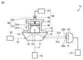
図1を参照して、実施の形態1の生体成分測定装置1を説明する。生体成分測定装置1は、光学媒質10と、励起光源16と、プローブ光源20と、光位置検出器25と、生体成分取得部27とを主に備える。Embodiment 1.
The biological component measuring device 1 of the first embodiment will be described with reference to FIG. The biological component measuring device 1 mainly includes an
光学媒質10は、第1面11と、第1面11とは反対側の第2面12と、第1面11と第2面12とを接続する第3面13と、第1面11と第2面12とを接続しかつ第3面13とは反対側の第4面14とを含む。光学媒質10の第1面11は、励起光源16から放射される励起光17の入射面である。第2面12は、サンプル載置面である。サンプル5は、第2面12上に載置され、第2面12と接触している。サンプル5は、例えば、患者の皮膚または体液などである。被測定物質が液体である場合、サンプル5は、透明なサンプルホルダに収容されている液体である。第3面13は、プローブ光源20から放射されるプローブ光21の入射面である。第3面13の法線方向は、プローブ光21の入射方向に対して傾いている。第4面14は、プローブ光21の出射面である。第4面14は、プローブ光21の出射方向に対して傾いている。光学媒質10は、例えば、内部全反射プリズム(TIRプリズム)であってもよい。
The
光学媒質10は、励起光17に対して透明である。本明細書において、光学媒質10が励起光17に対して透明であることは、励起光17に対する光学媒質10の光透過率が25%以上であることを意味する。励起光17に対する光学媒質10の光透過率は、50%以上であってもよく、75%以上であってもよく、90%以上であってもよい。光学媒質10は、プローブ光21に対して透明である。本明細書において、光学媒質10がプローブ光21に対して透明であることは、プローブ光21に対する光学媒質10の光透過率が25%以上であることを意味する。プローブ光21に対する光学媒質10の光透過率は、50%以上であってもよく、75%以上であってもよく、90%以上であってもよい。
The
光学媒質10は、15.0W/(m・K)以下の熱伝導率を有する材料で形成されている。光学媒質10を形成する材料の熱伝導率は、10.0W/(m・K)以下であってもよく、5.0W/(m・K)以下であってもよく、3.0W/(m・K)以下であってもよく、2.0W/(m・K)以下であってもよく、1.0W/(m・K)以下であってもよい。光学媒質10の材料の熱伝導率は、サンプル5の熱伝導率の0.5倍以上である。光学媒質10の材料の熱伝導率は、サンプル5の熱伝導率の0.75倍以上であってもよく、サンプル5の熱伝導率以上であってもよく、サンプル5の熱伝導率の1.5倍以上であってもよく、サンプル5の熱伝導率の2.0倍以上であってもよい。
The
光学媒質10は、カルコゲナイドガラスで形成されている。カルコゲナイドガラスは、例えば、2モル%以上22モル%以下のゲルマニウム(Ge)と、6モル%以上34モル%以下のアンチモン(Sb)及びビスマス(Bi)からなる群から選択される少なくとも1つの元素と、1モル%以上20モル%以下のスズ(Sn)と、58モル%以上70モル%以下の硫黄(S)、セレン(Se)及びテルル(Te)からなる群から選択される少なくとも1つの元素とを含有する。このカルコゲナイドガラスの熱伝導率は、0.36W/(m・K)である。
The
励起光源16は、サンプル載置面(第2面12)上に載置されるサンプル5に向けて励起光17を放射する。励起光17は、励起光源16から放射されて、第1面11から光学媒質10に入射する。励起光17は、光学媒質10中を進む。励起光17は、第2面12からサンプル5に入射する。励起光17は、サンプル5中のまたはサンプル5の表面6上の生体成分に吸収される。例えば、生体成分測定装置1を用いて患者の血糖値を得る場合、生体成分は、表皮中の組織間質液中に存在している糖である。生体成分による励起光17の吸収によって、サンプル5で吸収熱が発生する。サンプル5の吸収熱は、光学媒質10に伝導する。光学媒質10の内部に温度勾配領域が生じて、光学媒質10内部に屈折率勾配領域18が生じる。
The
励起光17の波長は、サンプル5中のまたはサンプル5の表面6上の生体成分の吸収波長に応じて定められる。励起光17の波長は、プローブ光21の波長よりも長くてもよい。励起光17の波長は、例えば、6.0μm以上である。励起光17の波長は、8.0μm以上であってもよい。励起光17の波長は、例えば、13.0μm以下である。励起光17の波長は、11.0μm以下であってもよい。励起光17は、複数の波長を有する光であってもよい。例えば、生体成分測定装置1を用いて患者の血糖値を測定する場合、励起光17の波長範囲は、糖の指紋スペクトルの波長を含む波長範囲(例えば、8.5μm以上10μm以下の波長範囲)である。励起光源16は、例えば、広帯域の赤外光を放射し得る量子カスケードレーザである。サンプル5中のまたはサンプル5の表面6上の生体成分に吸収されない参照光が、励起光17とともにサンプル5に照射されてもよい。
The wavelength of the
プローブ光源20は、プローブ光21を放射する。プローブ光21は、光学媒質10の第3面13から光学媒質10に入射する。プローブ光21は、第3面13で屈折されて、光学媒質10(第2面12)とサンプル5との間の界面に向けて、光学媒質10中を進む。サンプル載置面(第2面12)の平面視において、光学媒質10中におけるプローブ光21の光路は、サンプル載置面(第2面12)のうち励起光17によって照射される部分と重なっている。プローブ光21は、光学媒質10(第2面12)とサンプル5との間の界面で内部全反射される。プローブ光21が光学媒質10中を進む間、プローブ光21は、サンプル5の吸収熱により光学媒質10内に生じた屈折率勾配領域18中を進む。プローブ光21は、屈折率勾配領域18で屈折されて、プローブ光21の進行方向が変わる。プローブ光21(第1出射プローブ光21a、第2出射プローブ光21b)は、光学媒質10の第4面14から出射される。
The
プローブ光21の波長は、例えば、1100nm以上である。プローブ光21の波長は、1300nm以上であってもよい。プローブ光21の波長は、例えば、1700nm以下である。そのため、プローブ光21の光源として、InGaAsP系半導体レーザまたはInGaNAs系半導体レーザのような安価な光通信用半導体レーザを用いることができる。さらに、プローブ光21は可視光ではないため、プローブ光21が人の眼に損傷を与えるリスクが低減され得る。プローブ光21の出力は、例えば、5mW以下である。そのため、プローブ光21が人の眼に損傷を与えるリスクが低減され得る。
The wavelength of the
光位置検出器25は、光学媒質10から出射されるプローブ光21(第1出射プローブ光21a、第2出射プローブ光21b)の位置を検出する。光位置検出器25は、励起光17がサンプル5に照射されていない時におけるプローブ光21(第1出射プローブ光21a)の第1位置22aを検出する。プローブ光21(第1出射プローブ光21a)の第1位置22aは、励起光17をサンプル5に照射していない時に光位置検出器25で検出されるプローブ光21(第1出射プローブ光21a)の位置である。光位置検出器25は、励起光17がサンプル5に照射されている時におけるプローブ光21(第2出射プローブ光21b)の第2位置22bを検出する。プローブ光21(第2出射プローブ光21b)の第2位置22bは、励起光17をサンプル5に照射している時に、光位置検出器25で検出されるプローブ光21(第2出射プローブ光21b)の位置である。励起光17をサンプル5に照射することによって、光位置検出器25で検出されるプローブ光21の位置は、第1位置22aから第2位置22bに変位する。
The
光位置検出器25は、プローブ光21(第1出射プローブ光21a)の第1位置22aとプローブ光21(第2出射プローブ光21b)の第2位置22bとを、生体成分取得部27に出力する。光位置検出器25は、例えば、フォトダイオードまたは半導体位置検出素子である。
The
生体成分取得部27は、光位置検出器25に接続されている。生体成分取得部27は、第1位置22aと第2位置22bとの間の距離であるプローブ光21の変位量δを算出し、プローブ光21の変位量δから、サンプル5中のまたはサンプル5の表面6上の生体成分の量または濃度を得る。生体成分取得部27は、例えば、演算処理装置で実行される機能の一つである。
The biological
図2を参照して、生体成分測定装置1を用いた本実施の形態の生体成分測定方法を説明する。 With reference to FIG. 2, the biological component measuring method of the present embodiment using the biological component measuring device 1 will be described.
本実施の形態の生体成分測定方法は、励起光17をサンプル5に照射しないで、光位置検出器25を用いて、プローブ光21(第1出射プローブ光21a)の第1位置22aを検出することを備える(S1)。励起光17がサンプル5に照射されていないため、サンプル5で吸収熱は発生しない。光学媒質10の内部に温度勾配領域が生じず、光学媒質10の内部に屈折率勾配領域18も生じない。励起光17をサンプル5に照射していない時、プローブ光21(第1出射プローブ光21a)が光学媒質10から出射する。プローブ光21(第1出射プローブ光21a)の第1位置22aは、光位置検出器25で検出されるプローブ光21(第1出射プローブ光21a)の位置である。
In the biological component measuring method of the present embodiment, the
本実施の形態の生体成分測定方法は、励起光17をサンプル5に照射しながら、光位置検出器25を用いて、プローブ光21(第2出射プローブ光21b)の第2位置22bを検出することを備える(S2)。励起光17がサンプル5に照射されているため、励起光17は、サンプル5中のまたはサンプル5の表面6上の生体成分に吸収される。生体成分による励起光17の吸収によって、サンプル5で吸収熱が発生する。サンプル5の吸収熱は、光学媒質10に伝導する。光学媒質10の内部に温度勾配領域が生じて、光学媒質10の内部に屈折率勾配領域18が生じる。プローブ光21は、屈折率勾配領域18で屈折されて、プローブ光21の進行方向が変わる。励起光17をサンプル5に照射している時、プローブ光21(第2出射プローブ光21b)が光学媒質10から出射する。プローブ光21(第2出射プローブ光21b)の第2位置22bは、光位置検出器25で検出されるプローブ光21(第2出射プローブ光21b)の位置である。励起光17をサンプル5に照射することによって、光位置検出器25で検出されるプローブ光21の位置は、第1位置22aから第2位置22bに変位する。
In the biological component measuring method of the present embodiment, the
本実施の形態の生体成分測定方法は、プローブ光21の変位量δを算出することを備える(S3)。具体的には、生体成分取得部27は、第1位置22aと第2位置22bとの間の距離を算出して、プローブ光21の変位量δを得る。
The biological component measuring method of the present embodiment includes calculating the displacement amount δ of the probe light 21 (S3). Specifically, the biological
本実施の形態の生体成分測定方法は、プローブ光21の変位量δから、サンプル5中のまたはサンプル5の表面6上の生体成分の量または濃度を得ることを備える(S4)。例えば、生体成分取得部27は、メモリ(図示せず)に接続されている。メモリは、生体成分の種類と、プローブ光21の変位量δと、生体成分の量または濃度とが対応づけられているデータテーブルを格納している。生体成分取得部27は、データテーブルを参照して、生体成分の種類とプローブ光21の変位量δとに対応する生体成分の量または濃度を得る。
The biological component measuring method of the present embodiment comprises obtaining the amount or concentration of the biological component in the
図3を参照して、本実施の形態の第1変形例の生体成分測定装置1aを説明する。本実施の形態の第1変形例では、光学媒質10の第3面13の法線方向は、プローブ光21の入射方向に平行である。第4面14は、第3面13に平行である。プローブ光21は、サンプル載置面(第2面12)で内部全反射されることなく、サンプル載置面(第2面12)に沿って進む。生体成分測定装置1aを用いた生体成分測定方法は、生体成分測定装置1を用いた生体成分測定方法と同様である。本実施の形態の第2変形例では、プローブ光21がサンプル載置面(第2面12)とサンプル5との間の界面で複数回内部全反射されてもよい。
With reference to FIG. 3, the biological
本実施の形態の生体成分測定装置1,1aの効果を説明する。
本実施の形態の生体成分測定装置1,1aは、光学媒質10と、励起光源16と、プローブ光源20と、光位置検出器25とを備える。光学媒質10は、サンプル載置面(第2面12)を含む。励起光源16は、サンプル載置面(第2面12)上に載置されるサンプル5に向けて光学媒質10中を進む励起光17を放射する。プローブ光源20は、光学媒質10中を進むプローブ光21を放射する。光位置検出器25は、光学媒質10から出射されるプローブ光21の位置を検出する。サンプル載置面(第2面12)の平面視において、光学媒質10中におけるプローブ光21の光路は、サンプル載置面(第2面12)のうち励起光17によって照射される部分と重なっている。光学媒質10は、カルコゲナイドガラスで形成されている。The effects of the biological
The biological
カルコゲナイドガラスの熱伝導率は、硫化亜鉛(ZnS)の熱伝導率(27.2W/(m・K))よりも小さい。そのため、サンプル5の吸収熱が伝導して光学媒質10中に形成される屈折率勾配領域18における屈折率の変化が大きくなる。本実施の形態の生体成分測定装置1,1aは、向上された精度で生体成分を測定することを可能にする。
The thermal conductivity of chalcogenide glass is smaller than the thermal conductivity of zinc sulfide (ZnS) (27.2 W / (m · K)). Therefore, the absorption heat of the
本実施の形態の生体成分測定装置1,1aでは、プローブ光21の波長は、1300nm以上1700nm以下である。そのため、プローブ光21が人の眼に損傷を与えるリスクが低減され得る。また、プローブ光源20として安価な光通信用半導体レーザが利用可能であるため、生体成分測定装置1,1aのコストが低減され得る。
In the biological
本実施の形態の生体成分測定装置1では、プローブ光21はサンプル載置面(第2面12)で内部全反射される。そのため、プローブ光21が屈折率勾配領域18を通る距離を長くすることができる。本実施の形態の生体成分測定装置1は、向上された精度で生体成分を測定することを可能にする。
In the biological component measuring device 1 of the present embodiment, the
本実施の形態の生体成分測定装置1aでは、プローブ光21は、サンプル載置面(第2面12)で内部全反射されることなく、サンプル載置面(第2面12)に沿って進む。そのため、本実施の形態の生体成分測定装置1aは、向上された精度で生体成分を測定することを可能にする。
In the biological
本実施の形態の生体成分測定装置1,1aは、光位置検出器25に接続されている生体成分取得部27をさらに備える。光位置検出器25は、励起光17がサンプル5に照射されていない時におけるプローブ光21(第1出射プローブ光21a)の第1位置22aと、励起光17がサンプル5に照射されている時におけるプローブ光21(第2出射プローブ光21b)の第2位置22bとを、生体成分取得部27に出力する。生体成分取得部27は、第1位置22aと第2位置22bとの間の距離であるプローブ光21の変位量δを算出し、プローブ光21の変位量δからサンプル5中のまたはサンプル5の表面6上の生体成分の量または濃度を得る。そのため、本実施の形態の生体成分測定装置1,1aは、向上された精度で生体成分を測定することを可能にする。
The biological
本実施の形態の生体成分測定装置1,1aは、光学媒質10と、励起光源16と、プローブ光源20と、光位置検出器25とを備える。光学媒質10は、サンプル載置面(第2面12)を含む。励起光源16は、サンプル載置面(第2面12)上に載置されるサンプル5に向けて光学媒質10中を進む励起光17を放射する。プローブ光源20は、光学媒質10中を進むプローブ光21を放射する。光位置検出器25は、光学媒質10から出射されるプローブ光21の位置を検出する。サンプル載置面(第2面12)の平面視において、光学媒質10中におけるプローブ光21の光路は、サンプル載置面(第2面12)のうち励起光17によって照射される部分と重なっている。光学媒質10は、15.0W/(m・K)以下の熱伝導率を有する材料で形成されている。
The biological
そのため、光学媒質10の材料の熱伝導率は、硫化亜鉛(ZnS)の熱伝導率(27.2W/(m・K))よりも小さい。サンプル5の吸収熱が伝導して光学媒質10中に形成される屈折率勾配領域18における屈折率の変化が大きくなる。本実施の形態の生体成分測定装置1,1aは、向上された精度で生体成分を測定することを可能にする。
Therefore, the thermal conductivity of the material of the
本実施の形態の生体成分測定装置1,1aでは、光学媒質10の材料の熱伝導率は、1.0W/(m・K)以下である。そのため、光学媒質10の材料の熱伝導率は、硫化亜鉛(ZnS)の熱伝導率(27.2W/(m・K))よりも小さい。サンプル5の吸収熱が伝導して光学媒質10中に形成される屈折率勾配領域18における屈折率の変化が大きくなる。本実施の形態の生体成分測定装置1,1aは、向上された精度で生体成分を測定することを可能にする。
In the biological
本実施の形態の生体成分測定装置1,1aでは、光学媒質10の材料の熱伝導率は、サンプル5の熱伝導率の0.5倍以上である。そのため、サンプル5で発生した吸収熱の多くがサンプル5に散逸することが防止されて、この吸収熱は光学媒質10に伝導する。本実施の形態の生体成分測定装置1,1aは、向上された精度で生体成分を測定することを可能にする。
In the biological
実施の形態2.
図4を参照して、実施の形態2の生体成分測定装置1bを説明する。本実施の形態の生体成分測定装置1bは、実施の形態1の生体成分測定装置1と同様の構成を備えるが、以下の点で主に異なる。Embodiment 2.
The biological
生体成分測定装置1bは、光チョッパー30と、ロックインアンプ31とをさらに備える。光チョッパー30は、励起光17の光路中に配置される。光チョッパー30は励起光17を任意の周波数でチョッピングする。ロックインアンプ31は、光チョッパー30と光位置検出器25とに接続されている。ロックインアンプ31は、光位置検出器25から出力されるプローブ光21の位置に関する信号のうち、光チョッパー30のチョッピング周波数に同期する信号を選択的に増幅する。そのため、光位置検出器25から出力されるプローブ光21の位置に関する信号に含まれるノイズが除去され得る。生体成分測定装置1bは、向上された精度で生体成分を測定することを可能にする。
The biological
実施の形態3.
図5を参照して、実施の形態3の生体成分測定装置1cを説明する。本実施の形態の生体成分測定装置1cは、実施の形態1の生体成分測定装置1と同様の構成を備えるが、以下の点で主に異なる。Embodiment 3.
The biological
生体成分測定装置1cは、温度センサ35をさらに備える。生体成分測定装置1cは、ディスプレイ36をさらに備えてもよい。温度センサ35は、例えば、光学媒質10のうち、サンプル5と励起光17とプローブ光21とから離れた部分上に取り付けられている。特定的には、温度センサ35は、光学媒質10のサンプル載置面(第2面12)のうち、サンプル5と励起光17とプローブ光21とから離れた部分上に取り付けられている。温度センサ35は、光学媒質10の温度を測定する。温度センサ35は、光学媒質10の温度に関する第1信号を、ディスプレイ36に出力する。温度センサ35は、例えば、サーミスタである。ディスプレイ36は、光学媒質10の温度または単位時間当たりの光学媒質10の温度の変動幅を表示する。ディスプレイ36は、例えば、液晶表示装置などである。
The biological
光学媒質10の第1温度とサンプル5の第2温度との間に差があると、光学媒質10とサンプル5との間で熱の移動が発生する。この熱の移動は、光学媒質10の内部に生じる屈折率勾配領域18に影響を与え、生体成分を正確に測定することを困難にする。光学媒質10は、カルコゲナイドガラスのような低い熱伝導率を有する材料で形成されているため、単位時間当たりの光学媒質10の第1温度の変動幅が許容温度変動幅(例えば0.1℃/分)より大きい状態(熱非平衡状態)から、単位時間当たりの光学媒質10の第1温度の変動幅が許容温度変動幅(例えば0.1℃/分)以下の状態(熱非平衡状態)に達するまで、より長い時間がかかる。
If there is a difference between the first temperature of the
生体成分測定装置1cでは、温度センサ35を用いて、単位時間当たりの光学媒質10の第1温度の変動幅、すなわち、光学媒質10とサンプル5との間の熱の移動の程度が分かる。光学媒質10のサンプル載置面(第2面12)にサンプル5を載置した後、温度センサ35で測定される単位時間当たりの光学媒質10の第1温度の変動幅が許容温度変動幅(例えば0.1℃/分)より大きい間(熱非平衡状態)は、生体成分測定装置1cを用いた生体成分の測定を行わない。光学媒質10のサンプル載置面(第2面12)にサンプル5を載置した後、単位時間当たりの光学媒質10の第1温度の変動幅が許容温度変動幅(例えば0.1℃/分)以下(熱平衡状態)となると、生体成分測定装置1cを用いて生体成分の測定を開始する。
In the biological
本実施の形態の生体成分測定装置1cは、実施の形態1の生体成分測定装置1の効果に加えて、以下の効果をさらに奏する。
The biological
本実施の形態の生体成分測定装置1cは、光学媒質10の温度を測定する温度センサ35をさらに備える。そのため、温度センサ35を用いて、光学媒質10とサンプル5との間の熱の移動に起因する光学媒質10の温度の変動を測定することができる。光学媒質10は、カルコゲナイドガラスのような低い熱伝導率を有する材料で形成されていても、光学媒質10とサンプル5との間の熱の移動に起因する悪影響がなく生体成分を測定することができるタイミングが正確に分かる。本実施の形態の生体成分測定装置1cは、向上された精度で生体成分を測定することを可能にする。
The biological
実施の形態4.
図6を参照して、実施の形態4の生体成分測定装置1dを説明する。本実施の形態の生体成分測定装置1dは、実施の形態3の生体成分測定装置1cと同様の構成を備えるが、以下の点で主に異なる。Embodiment 4.
The biological
生体成分測定装置1dは、温度調節器37と、温度コントローラ38とをさらに備える。温度調節器37は、例えば、光学媒質10のうち、サンプル5と励起光17とプローブ光21とから離れた部分上に取り付けられている。特定的には、温度調節器37は、光学媒質10のサンプル載置面(第2面12)のうち、サンプル5と励起光17とプローブ光21とから離れた部分上に取り付けられている。温度調節器37は、光学媒質10の温度を調整する。温度調節器37は、例えば、ペルチェ素子または電熱線である。温度センサ35は、光学媒質10の温度に関する第1信号を、温度コントローラ38にも出力する。
The biological
温度コントローラ38は、温度センサ35と温度調節器37とに接続されている。温度コントローラ38は、温度センサ35から出力される光学媒質10の温度に関する第1信号に基づいて温度調節器37を制御する。具体的には、温度センサ35で測定される単位時間当たりの光学媒質10の第1温度の変動幅が許容温度変動幅(例えば0.1℃/分)以下となるように、温度調節器37を制御する。例えば、光学媒質10の第1温度がサンプル5の第2温度よりも低く、かつ、単位時間当たりの光学媒質10の第1温度の変動幅が許容温度変動幅より大きい場合には、温度調節器37が光学媒質10を加熱するように、温度コントローラ38は温度調節器37を制御する。光学媒質10の第1温度がサンプル5の第2温度よりも高く、かつ、単位時間当たりの光学媒質10の第1温度の変動幅が許容温度変動幅より大きい場合には、温度調節器37が光学媒質10を冷却するように、温度コントローラ38は温度調節器37を制御する。
The
本実施の形態の生体成分測定装置1dは、実施の形態3の生体成分測定装置1cの効果に加えて、以下の効果をさらに奏する。
The biological
本実施の形態の生体成分測定装置1dは、光学媒質10の温度を調整する温度調節器37と、温度コントローラ38とをさらに備える。温度コントローラ38は、温度センサ35から出力される光学媒質10の温度に関する第1信号に基づいて温度調節器37を制御する。そのため、光学媒質10は、カルコゲナイドガラスのような低い熱伝導率を有する材料で形成されていても、光学媒質10のサンプル載置面(第2面12)にサンプル5を載置してから、光学媒質10とサンプル5との間の熱の移動が実質的になくなって生体成分を測定可能になるまでの時間が短縮され得る。生体成分測定装置1dは、向上された精度でかつより短時間で生体成分を測定することを可能にする。
The biological
実施の形態5.
図7及び図8を参照して、実施の形態5の生体成分測定装置1eを説明する。本実施の形態の生体成分測定装置1eは、実施の形態1の生体成分測定装置1と同様の構成を備えるが、以下の点で主に異なる。
The biological
生体成分測定装置1eは、プローブ光21の進行方向(図7の左右方向)におけるサンプル5の位置を規定する位置決め部材40をさらに備える。位置決め部材40は、一対の挟持部材41と、一対の挟持部材41を互いに連結する連結部材42とを含む。一対の挟持部材41の各々は、底板41aと、底板41aからサンプル載置面(第2面12)の法線方向に沿って延在する壁41bとを含む。底板41aは、サンプル載置面(第2面12)に面接触する。壁41bは、サンプル5の側面に接触する。一対の挟持部材41の一対の壁41bは、プローブ光21の進行方向において、サンプル5を挟持する。
The biological
生体成分測定装置1eは、押圧部44と、圧力センサ48と、圧力コントローラ49とをさらに備える。押圧部44は、サンプル5をサンプル載置面(第2面12)に向けて押圧する。押圧部44は、例えば、押圧板45と、押圧板45をサンプル載置面(第2面12)の法線方向に沿って移動させるボールねじ46と、ボールねじ46を回転させるモータ47とを含む。本実施の形態の変形例では、押圧板45は、ばねのような弾性部材を用いてサンプル5に向けて付勢されてもよい。
The biological
圧力センサ48は、押圧部44に設けられている。特定的には、圧力センサ48は、押圧板45に設けられている。圧力センサ48は、押圧部44がサンプル5を押圧する圧力を測定する。圧力センサ48は、押圧部44がサンプル5を押圧する圧力に関する第2信号を、圧力コントローラ49に出力する。圧力センサ48は、例えば、ゲージ式圧力センサまたは静電容量型圧力センサである。
The
図8に示されるように、圧力コントローラ49は、押圧部44(例えば、モータ47)と圧力センサ48とに接続されている。圧力コントローラ49は、圧力センサ48から出力される圧力に関する第2信号に基づいて押圧部44を制御する。例えば、サンプル5に印加されかつ圧力センサ48で測定される圧力が基準圧力となるように、押圧部44(モータ47)を制御する。具体的には、サンプル5に印加される圧力が基準圧力よりも低い場合には、サンプル5に印加される圧力が基準圧力に等しくなるように、圧力コントローラ49は、押圧板45をサンプル載置面(第2面12)に向けて移動させる。サンプル5に印加される圧力が基準圧力よりも高い場合には、サンプル5に印加される圧力が基準圧力に等しくなるように、圧力コントローラ49は、押圧板45をサンプル載置面(第2面12)から離れるように移動させる。
As shown in FIG. 8, the
本実施の形態の生体成分測定装置1eは、実施の形態1の生体成分測定装置1の効果に加えて、以下の効果をさらに奏する。
The biological
本実施の形態の生体成分測定装置1eは、押圧部44と、圧力センサ48と、圧力コントローラ49とをさらに備える。押圧部44は、サンプル5をサンプル載置面(第2面12)に向けて押圧する。圧力センサ48は、押圧部44がサンプル5を押圧する圧力を測定する。圧力コントローラ49は、圧力センサ48から出力される圧力に関する第2信号に基づいて押圧部44を制御する。そのため、光学媒質10へのサンプル5の接触圧を一定にすることができる。サンプル5の吸収熱の光学媒質10への伝導が安定化される。生体成分測定装置1eは、向上された精度で生体成分を測定することを可能にする。
The biological
本実施の形態の生体成分測定装置1eは、プローブ光21の進行方向におけるサンプル5の位置を規定する位置決め部材40をさらに備える。そのため、サンプル5が患者の指のような可動サンプルであっても、プローブ光21の進行方向において、励起光17及びプローブ光21に対してサンプル5を位置決めすることができる。生体成分測定装置1eは、向上された精度で生体成分を測定することを可能にする。
The biological
実施の形態6.
図9を参照して、実施の形態6の生体成分測定装置1fを説明する。本実施の形態の生体成分測定装置1fは、実施の形態1の生体成分測定装置1と同様の構成を備えるが、以下の点で主に異なる。生体成分測定装置1fは、光強度検出器51と、光源コントローラ52とをさらに備える。生体成分測定装置1fは、光ビームスプリッタ50をさらに備えてもよい。
The biological component measuring device 1f of the sixth embodiment will be described with reference to FIG. 9. The biological component measuring device 1f of the present embodiment has the same configuration as the biological component measuring device 1 of the first embodiment, but is mainly different in the following points. The biological component measuring device 1f further includes a
光強度検出器51は、励起光源16から放射される励起光17の強度を検出する。光強度検出器51は、例えば、フォトダイオードである。具体的には、励起光17の光路に、光ビームスプリッタ50が配置されている。光ビームスプリッタ50は、例えば、プレート型光ビームスプリッタ、プリズム型光ビームスプリッタまたは光ファイバ型光ビームスプリッタである。光ビームスプリッタ50は、励起光17の一部を、光強度検出器51に向ける。例えば、光ビームスプリッタ50は、励起光17の一部を反射して、光強度検出器51に向ける。光強度検出器51は、励起光17の一部の光強度を検出する。光強度検出器51は、励起光17の強度に関する信号を出力する。
The
光源コントローラ52は、励起光源16に接続されている。光源コントローラ52は、励起光源16を制御する。例えば、光源コントローラ52は、励起光源16に注入する電流を制御して、励起光源16から放射される励起光17の強度を制御する。光源コントローラ52は、光強度検出器51に接続されている。光源コントローラ52は、光強度検出器51から、励起光17の強度に関する信号を受信する。励起光源16から放射される励起光17の強度が一定になるように、光源コントローラ52は、光強度検出器51によって検出された励起光17の強度に関する信号に基づいて励起光源16を制御する。
The
本実施の形態の生体成分測定装置1fは、実施の形態1の生体成分測定装置1の効果に加えて、以下の効果をさらに奏する。 The biological component measuring device 1f of the present embodiment further exerts the following effects in addition to the effects of the biological component measuring device 1 of the first embodiment.
本実施の形態の生体成分測定装置1fは、励起光17の光強度を検出する光強度検出器51と、光強度検出器51から出力される励起光17の強度に関する信号に基づいて励起光源16を制御する光源コントローラ52とをさらに備える。
The biological component measuring device 1f of the present embodiment is an
励起光源16を長時間にわたって動作させている間に、励起光源16から放射される励起光17の光強度が低下することがある。励起光17の光強度が低下すると、生体成分の測定精度が低下する。しかし、本実施の形態では、光源コントローラ52は、光強度検出器51から出力される励起光17の強度に関する信号に基づいて励起光源16を制御する。そのため、励起光源16から放射される励起光17の光強度を長時間にわたって維持することができる。生体成分測定装置1fは、長時間にわたって、向上された精度で生体成分を測定することを可能にする。
While the
今回開示された実施の形態1−6はすべての点で例示であって制限的なものではないと考えられるべきである。矛盾のない限り、今回開示された実施の形態1−6の少なくとも2つを組み合わせてもよい。例えば、実施の形態1の変形例に、実施の形態2−5を組み合わせてもよい。実施の形態2−5の各々に、実施の形態6を組み合わせてもよい。本開示の範囲は、上記した説明ではなく請求の範囲によって示され、請求の範囲と均等の意味および範囲内でのすべての変更が含まれることを意図される。 It should be considered that embodiments 1-6 disclosed this time are exemplary in all respects and not restrictive. As long as there is no contradiction, at least two of Embodiments 1-6 disclosed this time may be combined. For example, the modified example of the first embodiment may be combined with the second embodiment of the second embodiment. Each of the 2-5 embodiments may be combined with the 6th embodiment. The scope of this disclosure is set forth by the claims rather than the description above and is intended to include all modifications within the meaning and scope of the claims.
1,1a,1b,1c,1d,1e,1f 生体成分測定装置、5 サンプル、6 表面、10 光学媒質、11 第1面、12 第2面、13 第3面、14 第4面、16 励起光源、17 励起光、18 屈折率勾配領域、20 プローブ光源、21 プローブ光、21a 第1出射プローブ光、21b 第2出射プローブ光、22a 第1位置、22b 第2位置、25 光位置検出器、27 生体成分取得部、30 光チョッパー、31 ロックインアンプ、35 温度センサ、36 ディスプレイ、37 温度調節器、38 温度コントローラ、40 位置決め部材、41 挟持部材、41a 底板、41b 壁、42 連結部材、44 押圧部、45 押圧板、46 ボールねじ、47 モータ、48 圧力センサ、49 圧力コントローラ、50 光ビームスプリッタ、51 光強度検出器51、52 光源コントローラ。
1,1a, 1b, 1c, 1d, 1e, 1f Biocomponent measuring device, 5 samples, 6 surfaces, 10 optical media, 11 1st surface, 12 2nd surface, 13 3rd surface, 14 4th surface, 16 excitation Light source, 17 excitation light, 18 refractive index gradient region, 20 probe light source, 21 probe light, 21a first exit probe light, 21b second exit probe light, 22a first position, 22b second position, 25 optical position detector, 27 Biocomponent acquisition unit, 30 Optical chopper, 31 Lock-in amplifier, 35 Temperature sensor, 36 Display, 37 Temperature controller, 38 Temperature controller, 40 Positioning member, 41 Holding member, 41a bottom plate, 41b wall, 42 Connecting member, 44 Pressing section, 45 pressing plate, 46 ball screw, 47 motor, 48 pressure sensor, 49 pressure controller, 50 optical beam splitter, 51
Claims (9)
前記生体サンプルを載置する生体サンプル載置面を含み、前記励起光に対して透明であり、硫化亜鉛の熱伝導率よりも小さい熱伝導率を有するカルコゲナイドガラスで形成され、前記励起光を吸収した前記生体サンプルの前記発熱によって屈折率が変化する光学媒質と、
前記生体サンプル載置面に向けて前記光学媒質中を進む前記励起光を放射する励起光源と、
前記光学媒質中を進むプローブ光を放射するプローブ光源と、
前記光学媒質から出射される前記プローブ光の位置を検出する光位置検出器と、
前記光学媒質の温度を測定する温度センサとを備え、
前記光学媒質は、前記プローブ光に対しても透明であり、
前記光位置検出器は、前記励起光源が前記励起光を放射していない場合に前記光学媒質から出射される前記プローブ光の第1位置と、前記励起光源が前記励起光を放射している場合に前記励起光による前記発熱によって屈折率勾配領域が生じた前記光学媒質から出射される前記プローブ光の第2位置とを検出し、
前記第1位置および前記第2位置に基づいて前記成分を測定し、
前記温度センサは、前記生体サンプル載置面のうち、前記生体サンプルと前記励起光と前記プローブ光とから離れた部分上に取り付けられている、生体成分測定装置。 In a biological component measuring device that measures components using the heat generated by a biological sample that has absorbed excitation light.
It is made of chalcogenide glass that contains a biological sample mounting surface on which the biological sample is placed, is transparent to the excitation light, and has a thermal conductivity lower than that of zinc sulfide, and absorbs the excitation light. An optical medium whose refractive index changes due to the heat generated by the biological sample,
An excitation light source that radiates the excitation light traveling in the optical medium toward the biological sample mounting surface,
A probe light source that radiates probe light traveling through the optical medium,
A light position detector for detecting a position of the probe light emitted from the optical medium,
A temperature sensor for measuring the temperature of the optical medium is provided.
The optical medium is also transparent to the probe light and is transparent.
The optical position detector includes a first position of the probe light emitted from the optical medium when the excitation light source does not emit the excitation light, and a case where the excitation light source emits the excitation light. The second position of the probe light emitted from the optical medium in which the refractive index gradient region is generated by the heat generated by the excitation light is detected.
The component was measured based on the first position and the second position .
The temperature sensor is a biological component measuring device mounted on a portion of the biological sample mounting surface that is separated from the biological sample, the excitation light, and the probe light.
前記光チョッパーと前記光位置検出器とに接続されているロックインアンプとをさらに備える、請求項1または請求項2に記載の生体成分測定装置。 An optical chopper arranged in the optical path of the excitation light,
The biological component measuring apparatus according to claim 1 or 2, further comprising a lock-in amplifier connected to the optical chopper and the optical position detector.
前記温度センサから出力される前記光学媒質の前記温度に関する第1信号に基づいて前記温度調節器を制御する温度コントローラとをさらに備える、請求項1から請求項3のいずれか一項に記載の生体成分測定装置。 A temperature controller that adjusts the temperature of the optical medium, and
The living body according to any one of claims 1 to 3 , further comprising a temperature controller that controls the temperature controller based on a first signal regarding the temperature of the optical medium output from the temperature sensor. Component measuring device.
前記押圧部が前記生体サンプルを押圧する圧力を測定する圧力センサと、
前記圧力センサから出力される前記圧力に関する第2信号に基づいて前記押圧部を制御する圧力コントローラとをさらに備える、請求項1から請求項4のいずれか一項に記載の生体成分測定装置。 A pressing portion that presses the biological sample toward the biological sample mounting surface, and a pressing portion.
A pressure sensor that measures the pressure at which the pressing portion presses the biological sample,
The biological component measuring apparatus according to any one of claims 1 to 4 , further comprising a pressure controller for controlling the pressing portion based on a second signal regarding the pressure output from the pressure sensor.
前記光位置検出器は、前記第1位置と前記第2位置とを前記生体成分取得部に出力し、
前記生体成分取得部は、前記第1位置と前記第2位置との間の距離である前記プローブ光の変位量を算出し、前記変位量から前記生体サンプル中のまたは前記生体サンプルの表面上の前記成分の量または濃度を得る、請求項1から請求項8のいずれか一項に記載の生体成分測定装置。 Further equipped with a biological component acquisition unit connected to the optical position detector,
The optical position detector outputs the first position and the second position to the biological component acquisition unit, and outputs the first position and the second position to the biological component acquisition unit.
The biological component acquisition unit calculates the displacement amount of the probe light, which is the distance between the first position and the second position, and from the displacement amount, is in the biological sample or on the surface of the biological sample. The biological component measuring apparatus according to any one of claims 1 to 8 , which obtains the amount or concentration of the component.
Applications Claiming Priority (3)
| Application Number | Priority Date | Filing Date | Title |
|---|---|---|---|
| JP2019231088 | 2019-12-23 | ||
| JP2019231088 | 2019-12-23 | ||
| PCT/JP2020/028648 WO2021131126A1 (en) | 2019-12-23 | 2020-07-27 | Biological component measurement device |
Publications (2)
| Publication Number | Publication Date |
|---|---|
| JP6985561B2 true JP6985561B2 (en) | 2021-12-22 |
| JPWO2021131126A1 JPWO2021131126A1 (en) | 2021-12-23 |
Family
ID=76574129
Family Applications (1)
| Application Number | Title | Priority Date | Filing Date |
|---|---|---|---|
| JP2021500479A Active JP6985561B2 (en) | 2019-12-23 | 2020-07-27 | Biological composition measuring device |
Country Status (5)
| Country | Link |
|---|---|
| US (1) | US20220404275A1 (en) |
| JP (1) | JP6985561B2 (en) |
| CN (1) | CN114829903A (en) |
| DE (1) | DE112020006295T5 (en) |
| WO (1) | WO2021131126A1 (en) |
Cited By (1)
| Publication number | Priority date | Publication date | Assignee | Title |
|---|---|---|---|---|
| KR102617817B1 (en) * | 2023-01-20 | 2023-12-27 | 주식회사 뷰텔 | A no-invasive glucose mensurement device and method including a motor for pressing a finger to close contact with an inner seat |
Families Citing this family (2)
| Publication number | Priority date | Publication date | Assignee | Title |
|---|---|---|---|---|
| JP7205002B1 (en) * | 2022-02-17 | 2023-01-16 | 三菱電機株式会社 | Non-invasive material analyzer |
| JP7466817B1 (en) | 2023-07-19 | 2024-04-12 | 三菱電機株式会社 | Analysis equipment |
Family Cites Families (10)
| Publication number | Priority date | Publication date | Assignee | Title |
|---|---|---|---|---|
| JPS61122548A (en) * | 1984-11-20 | 1986-06-10 | Canon Inc | Measuring instrument for light absorption characteristic of thin film |
| JP2005334281A (en) * | 2004-05-26 | 2005-12-08 | Matsushita Electric Works Ltd | Method and apparatus for measuring biological signal |
| JP4755016B2 (en) * | 2006-05-11 | 2011-08-24 | 日本電信電話株式会社 | Component concentration measuring device |
| US7956328B2 (en) * | 2009-07-29 | 2011-06-07 | Battelle Memorial Institute | System, device, and methods for real-time screening of live cells, biomarkers, and chemical signatures |
| DE102014108424B3 (en) | 2014-06-16 | 2015-06-11 | Johann Wolfgang Goethe-Universität | Non-invasive substance analysis |
| EP3524962A1 (en) * | 2015-12-09 | 2019-08-14 | Diamontech GmbH | Device and method for analysing a material |
| DE102015122995A1 (en) * | 2015-12-30 | 2017-07-06 | Blue Ocean Nova AG | Device for analyzing a product to be analyzed located in a product room |
| US11197614B2 (en) * | 2016-12-26 | 2021-12-14 | Mitsubishi Electric Corporation | Biological material measuring apparatus and method of measuring biological material |
| JP2018194423A (en) * | 2017-05-17 | 2018-12-06 | 住友電気工業株式会社 | Optical module and detection device |
| JP6425861B1 (en) * | 2018-02-02 | 2018-11-21 | 三菱電機株式会社 | Biological substance measuring device |
-
2020
- 2020-07-27 CN CN202080088145.5A patent/CN114829903A/en active Pending
- 2020-07-27 WO PCT/JP2020/028648 patent/WO2021131126A1/en active Application Filing
- 2020-07-27 JP JP2021500479A patent/JP6985561B2/en active Active
- 2020-07-27 US US17/772,527 patent/US20220404275A1/en active Pending
- 2020-07-27 DE DE112020006295.3T patent/DE112020006295T5/en active Pending
Cited By (1)
| Publication number | Priority date | Publication date | Assignee | Title |
|---|---|---|---|---|
| KR102617817B1 (en) * | 2023-01-20 | 2023-12-27 | 주식회사 뷰텔 | A no-invasive glucose mensurement device and method including a motor for pressing a finger to close contact with an inner seat |
Also Published As
| Publication number | Publication date |
|---|---|
| DE112020006295T5 (en) | 2022-11-10 |
| JPWO2021131126A1 (en) | 2021-12-23 |
| US20220404275A1 (en) | 2022-12-22 |
| CN114829903A (en) | 2022-07-29 |
| WO2021131126A1 (en) | 2021-07-01 |
Similar Documents
| Publication | Publication Date | Title |
|---|---|---|
| JP6985561B2 (en) | Biological composition measuring device | |
| CN108369183B (en) | Device and method for analyzing materials | |
| JP6858565B2 (en) | Non-invasive substance analysis | |
| JP4638055B2 (en) | Non-invasive measurement of analyte concentration in biological samples | |
| JP7254080B2 (en) | Device and method for analyzing substances | |
| JP5581222B2 (en) | Apparatus and method for non-invasive measurement of the concentration of a substance in the blood of a subject | |
| WO2006079797A2 (en) | Apparatus for measurement of analyte concentration | |
| US8219169B2 (en) | Apparatus and method using light retro-reflected from a retina to non-invasively measure the blood concentration of a substance | |
| JP6425861B1 (en) | Biological substance measuring device | |
| JP6786027B1 (en) | Biological composition measuring device | |
| US9332936B2 (en) | Concentration determination apparatus and concentration determination method for detecting an absorbance of living body tissue based on a light intensity and measuring a concentration of a measured component contained in living body tissue | |
| JP4047907B2 (en) | Biological information measuring optical element and biological information measuring apparatus using the same | |
| WO2022201301A1 (en) | Biological component measurement device and biological component measurement method | |
| CN113349768A (en) | Measurement device and biological information measurement device | |
| JP7205002B1 (en) | Non-invasive material analyzer | |
| JP2018139952A (en) | Optical measuring device | |
| JP2004321368A (en) | Apparatus for measuring glucose concentration | |
| JP7363368B2 (en) | Absorbance measuring device and biological information measuring device | |
| JP7476317B2 (en) | Non-invasive material analysis device | |
| JP2006296660A (en) | Biological information measuring method, biological information measuring optical element and biological information measuring apparatus | |
| JP7447433B2 (en) | Optical members, biological information measuring devices, and measuring devices | |
| JP7354778B2 (en) | Measuring device and biological information measuring device | |
| JP7439456B2 (en) | Biological information measuring device and biological information measuring method | |
| JP6946707B2 (en) | Detection device and biological information measuring device | |
| TW202208830A (en) | Blood measuring device |
Legal Events
| Date | Code | Title | Description |
|---|---|---|---|
| A521 | Request for written amendment filed |
Free format text: JAPANESE INTERMEDIATE CODE: A523 Effective date: 20210107 |
|
| A621 | Written request for application examination |
Free format text: JAPANESE INTERMEDIATE CODE: A621 Effective date: 20210107 |
|
| A871 | Explanation of circumstances concerning accelerated examination |
Free format text: JAPANESE INTERMEDIATE CODE: A871 Effective date: 20210107 |
|
| A975 | Report on accelerated examination |
Free format text: JAPANESE INTERMEDIATE CODE: A971005 Effective date: 20210402 |
|
| A131 | Notification of reasons for refusal |
Free format text: JAPANESE INTERMEDIATE CODE: A131 Effective date: 20210413 |
|
| A521 | Request for written amendment filed |
Free format text: JAPANESE INTERMEDIATE CODE: A523 Effective date: 20210611 |
|
| A02 | Decision of refusal |
Free format text: JAPANESE INTERMEDIATE CODE: A02 Effective date: 20210831 |
|
| A521 | Request for written amendment filed |
Free format text: JAPANESE INTERMEDIATE CODE: A523 Effective date: 20211020 |
|
| C60 | Trial request (containing other claim documents, opposition documents) |
Free format text: JAPANESE INTERMEDIATE CODE: C60 Effective date: 20211020 |
|
| A911 | Transfer to examiner for re-examination before appeal (zenchi) |
Free format text: JAPANESE INTERMEDIATE CODE: A911 Effective date: 20211028 |
|
| C21 | Notice of transfer of a case for reconsideration by examiners before appeal proceedings |
Free format text: JAPANESE INTERMEDIATE CODE: C21 Effective date: 20211102 |
|
| A01 | Written decision to grant a patent or to grant a registration (utility model) |
Free format text: JAPANESE INTERMEDIATE CODE: A01 Effective date: 20211124 |
|
| A61 | First payment of annual fees (during grant procedure) |
Free format text: JAPANESE INTERMEDIATE CODE: A61 Effective date: 20211125 |