JP6980917B2 - Magnetic resonance imaging system with RF motion detection - Google Patents
Magnetic resonance imaging system with RF motion detection Download PDFInfo
- Publication number
- JP6980917B2 JP6980917B2 JP2020527099A JP2020527099A JP6980917B2 JP 6980917 B2 JP6980917 B2 JP 6980917B2 JP 2020527099 A JP2020527099 A JP 2020527099A JP 2020527099 A JP2020527099 A JP 2020527099A JP 6980917 B2 JP6980917 B2 JP 6980917B2
- Authority
- JP
- Japan
- Prior art keywords
- signal
- magnetic resonance
- coil
- patient
- sensor
- Prior art date
- Legal status (The legal status is an assumption and is not a legal conclusion. Google has not performed a legal analysis and makes no representation as to the accuracy of the status listed.)
- Active
Links
Images


Classifications
-
- G—PHYSICS
- G01—MEASURING; TESTING
- G01R—MEASURING ELECTRIC VARIABLES; MEASURING MAGNETIC VARIABLES
- G01R33/00—Arrangements or instruments for measuring magnetic variables
- G01R33/20—Arrangements or instruments for measuring magnetic variables involving magnetic resonance
- G01R33/44—Arrangements or instruments for measuring magnetic variables involving magnetic resonance using nuclear magnetic resonance [NMR]
- G01R33/48—NMR imaging systems
- G01R33/54—Signal processing systems, e.g. using pulse sequences ; Generation or control of pulse sequences; Operator console
- G01R33/56—Image enhancement or correction, e.g. subtraction or averaging techniques, e.g. improvement of signal-to-noise ratio and resolution
- G01R33/567—Image enhancement or correction, e.g. subtraction or averaging techniques, e.g. improvement of signal-to-noise ratio and resolution gated by physiological signals, i.e. synchronization of acquired MR data with periodical motion of an object of interest, e.g. monitoring or triggering system for cardiac or respiratory gating
- G01R33/5673—Gating or triggering based on a physiological signal other than an MR signal, e.g. ECG gating or motion monitoring using optical systems for monitoring the motion of a fiducial marker
-
- G—PHYSICS
- G01—MEASURING; TESTING
- G01R—MEASURING ELECTRIC VARIABLES; MEASURING MAGNETIC VARIABLES
- G01R33/00—Arrangements or instruments for measuring magnetic variables
- G01R33/20—Arrangements or instruments for measuring magnetic variables involving magnetic resonance
- G01R33/28—Details of apparatus provided for in groups G01R33/44 - G01R33/64
- G01R33/32—Excitation or detection systems, e.g. using radio frequency signals
- G01R33/34—Constructional details, e.g. resonators, specially adapted to MR
- G01R33/34007—Manufacture of RF coils, e.g. using printed circuit board technology; additional hardware for providing mechanical support to the RF coil assembly or to part thereof, e.g. a support for moving the coil assembly relative to the remainder of the MR system
-
- G—PHYSICS
- G01—MEASURING; TESTING
- G01R—MEASURING ELECTRIC VARIABLES; MEASURING MAGNETIC VARIABLES
- G01R33/00—Arrangements or instruments for measuring magnetic variables
- G01R33/20—Arrangements or instruments for measuring magnetic variables involving magnetic resonance
- G01R33/28—Details of apparatus provided for in groups G01R33/44 - G01R33/64
- G01R33/32—Excitation or detection systems, e.g. using radio frequency signals
- G01R33/36—Electrical details, e.g. matching or coupling of the coil to the receiver
- G01R33/3692—Electrical details, e.g. matching or coupling of the coil to the receiver involving signal transmission without using electrically conductive connections, e.g. wireless communication or optical communication of the MR signal or an auxiliary signal other than the MR signal
-
- G—PHYSICS
- G01—MEASURING; TESTING
- G01R—MEASURING ELECTRIC VARIABLES; MEASURING MAGNETIC VARIABLES
- G01R33/00—Arrangements or instruments for measuring magnetic variables
- G01R33/20—Arrangements or instruments for measuring magnetic variables involving magnetic resonance
- G01R33/44—Arrangements or instruments for measuring magnetic variables involving magnetic resonance using nuclear magnetic resonance [NMR]
- G01R33/48—NMR imaging systems
- G01R33/54—Signal processing systems, e.g. using pulse sequences ; Generation or control of pulse sequences; Operator console
- G01R33/56—Image enhancement or correction, e.g. subtraction or averaging techniques, e.g. improvement of signal-to-noise ratio and resolution
- G01R33/565—Correction of image distortions, e.g. due to magnetic field inhomogeneities
- G01R33/56509—Correction of image distortions, e.g. due to magnetic field inhomogeneities due to motion, displacement or flow, e.g. gradient moment nulling
-
- G—PHYSICS
- G01—MEASURING; TESTING
- G01R—MEASURING ELECTRIC VARIABLES; MEASURING MAGNETIC VARIABLES
- G01R33/00—Arrangements or instruments for measuring magnetic variables
- G01R33/20—Arrangements or instruments for measuring magnetic variables involving magnetic resonance
- G01R33/28—Details of apparatus provided for in groups G01R33/44 - G01R33/64
- G01R33/32—Excitation or detection systems, e.g. using radio frequency signals
- G01R33/34—Constructional details, e.g. resonators, specially adapted to MR
- G01R33/341—Constructional details, e.g. resonators, specially adapted to MR comprising surface coils
- G01R33/3415—Constructional details, e.g. resonators, specially adapted to MR comprising surface coils comprising arrays of sub-coils, i.e. phased-array coils with flexible receiver channels
Landscapes
- Physics & Mathematics (AREA)
- Health & Medical Sciences (AREA)
- Engineering & Computer Science (AREA)
- General Physics & Mathematics (AREA)
- Condensed Matter Physics & Semiconductors (AREA)
- Physiology (AREA)
- Biophysics (AREA)
- Life Sciences & Earth Sciences (AREA)
- Nuclear Medicine, Radiotherapy & Molecular Imaging (AREA)
- General Health & Medical Sciences (AREA)
- Radiology & Medical Imaging (AREA)
- Signal Processing (AREA)
- High Energy & Nuclear Physics (AREA)
- Pulmonology (AREA)
- Power Engineering (AREA)
- Cardiology (AREA)
- Computer Networks & Wireless Communication (AREA)
- Magnetic Resonance Imaging Apparatus (AREA)
Description
本発明は、磁気共鳴画像の生成用のRF信号を送信及び/又は受信するRFコイルを有するRFコイル装置を含む患者の磁気共鳴イメージング(MRI)検査用のMRIシステムに関し、特に、検査中の患者の動きを検出する可能性を有するMRIシステムに関する。 The present invention relates to an MRI system for a magnetic resonance imaging (MRI) examination of a patient comprising an RF coil device having an RF coil that transmits and / or receives an RF signal for the generation of a magnetic resonance image, in particular the patient under examination. With respect to an MRI system that has the potential to detect movements in.
当技術分野において一般に知られているように、磁気共鳴イメージングシステムでは、患者(通常は人間又は動物)が均一な主磁場(B0磁場)に晒されることで、患者内の原子核の磁気モーメントが、すべての原子核の特定の正味の磁化をB0磁場に平行に形成し、これを傾けることで、印加B0磁場の軸の周りの回転(ラーモア歳差運動)を生じさせることができる。歳差運動の速度はラーモア周波数と呼ばれ、これは、関与する原子核の特定の物理特性、具体的には磁気回転比と、印加B0磁場の強度とに依存する。磁気回転比は、磁気モーメントと原子核のスピンとの比である。 As is generally known in the art, in a magnetic resonance imaging system, a patient (usually a human or animal) is exposed to a uniform main magnetic field (B0 magnetic field), which causes the magnetic moment of the nucleus in the patient to be. A particular net magnetization of all nuclei can be formed parallel to the B0 magnetic field and tilted to cause rotation around the axis of the applied B0 magnetic field (Larmor precession). The velocity of precession is called the Larmor frequency, which depends on the specific physical characteristics of the nuclei involved, specifically the gyromagnetic ratio and the strength of the applied B0 magnetic field. The gyromagnetic ratio is the ratio of the magnetic moment to the spin of the nucleus.
B0磁場に対して直交偏波を有し、RF送信アンテナ又はコイルによって生成され且つ関心の原子核のラーモア周波数に一致するRF励起パルス(B1磁場)を送信することにより、原子核のスピンは励起されて揃えられ、それらの正味の磁化のB0磁場の方向からの偏向が得られるため、正味の磁化の縦成分に対する横成分が生成される。 The spin of the nucleus is excited by transmitting an RF excitation pulse (B1 magnetic field) that has orthogonal polarization to the B0 magnetic field and is generated by the RF transmit antenna or coil and that matches the Larmor frequency of the nucleus of interest. Since they are aligned and a deflection of their net magnetization from the direction of the B0 magnetic field is obtained, a horizontal component with respect to the vertical component of the net magnetization is generated.
RF励起パルスの終了後、正味の磁化がその平衡状態に戻るまで、正味の磁化の縦成分及び横成分の緩和過程が開始する。歳差運動する磁化によって生成されるMR(磁気共鳴)信号が、RF受信アンテナ又はコイルによって検出される。次に、時間ベースの振幅信号である受信MR信号は、周波数ベースのMRスペクトル信号にフーリエ変換され処理されて、患者内の関心の原子核のMR画像が生成される。 After the end of the RF excitation pulse, the relaxation process of the vertical and horizontal components of the net magnetization begins until the net magnetization returns to its equilibrium state. The MR (magnetic resonance) signal generated by the precessing magnetization is detected by the RF receiving antenna or coil. The received MR signal, which is a time-based amplitude signal, is then Fourier transformed into a frequency-based MR spectral signal and processed to generate an MR image of the nucleus of interest in the patient.
患者内のスライス又はボリュームの空間的選択と、関心のスライス又はボリュームから発せられる受信MR信号の空間エンコーディングとを得るために、B0磁場と同じ方向を有するが、直交するx、y及びz方向に勾配を有する傾斜磁場がB0磁場に重ね合わされる。ラーモア周波数は原子核に課される磁場の強度に依存することにより、原子核のラーモア周波数は、全体の重ね合わされたB0磁場の勾配の低下に沿って且つ当該低下と共に適宜低下する(この逆もまた同様である)。これにより、送信RF励起パルスの周波数を適切に調整することにより(また、それに応じてRF/MR受信アンテナの共振周波数を調整することにより)、また、傾斜磁場を適宜制御することにより、x、y及びz方向の各勾配に沿った特定の位置のスライス内での原子核の選択と、これにより、全体として、物体の特定のボクセル内での原子核の選択とを得ることができる。 To obtain the spatial selection of the slice or volume within the patient and the spatial encoding of the received MR signal emanating from the slice or volume of interest, it has the same direction as the B0 magnetic field, but in orthogonal x, y and z directions. A gradient magnetic field with a gradient is superimposed on the B0 magnetic field. Since the Larmor frequency depends on the strength of the magnetic field applied to the nucleus, the Larmor frequency of the nucleus decreases as appropriate along and with the decrease in the gradient of the overall superimposed B0 magnetic field (and vice versa). Is). Thereby, by appropriately adjusting the frequency of the transmission RF excitation pulse (and by adjusting the resonance frequency of the RF / MR receiving antenna accordingly), and by appropriately controlling the gradient magnetic field, x, It is possible to obtain the selection of nuclei within a slice at a particular position along each gradient in the y and z directions, thereby, as a whole, the selection of nuclei within a particular boxel of the object.
上記RF(送信及び/又は受信)アンテナは、患者全体を撮像するようにMRIシステムの検査空間内に固定して取り付けられるか、検査される局所的なゾーン又は領域のすぐ上又は付近に配置されるコイルの形で提供することができる。 The RF (radio frequency transmit and / or receive) antenna is fixedly mounted in the examination space of the MRI system to image the entire patient, or placed just above or near the local zone or area to be examined. Can be provided in the form of a coil.
MRIスキャンには、幾つかの入力パラメータと適切なスキャン準備とが必要である。通常、検査中の患者の体のサイズ及び体重、スキャンする患者の体位及び解剖学的構造に応じてプロトコルが選択され、患者に合うように変更される。通常、このデータは手動で入力する必要がある。例えばスキャンをトリガするために必要である生理学的パラメータは、専用センサを使用して測定する必要がある。しかし、MRI処置中、患者は衣服で覆われ、また、ほとんどの利用では、ヘッドコイル及び/又は(前)面コイルといったRFコイルで覆われる。したがって、患者の動きを検出するための光学的検出方法は、実現することが難しい。 An MRI scan requires some input parameters and proper scan preparation. Usually, the protocol is selected and modified to suit the patient, depending on the size and weight of the patient being examined, the position and anatomy of the patient to be scanned. This data usually needs to be entered manually. For example, the physiological parameters needed to trigger a scan need to be measured using a dedicated sensor. However, during the MRI procedure, the patient is covered with clothing and, in most applications, with RF coils such as head coils and / or (front) surface coils. Therefore, it is difficult to realize an optical detection method for detecting the movement of a patient.
これに関して、米国特許第4,712,560号から、MRIデータの収集をスライスの動きと同期させる際に使用するためにMRIシステムにおけるイメージングスライスの生理学的動きに対応する信号を提供する装置及び方法が知られている。信号は、所定周波数の入射信号を開始することによって生成され、この信号は、イメージングスライスと相互作用し、この周波数の反射信号を返す。入射信号と反射信号とを混合することにより、信号間の位相及び大きさの関係の変化を示すベースバンド信号が生成される。信号間の位相及び大きさの関係の変化は、イメージングスライスの動きにほぼ線形に関連しているため、ベースバンド信号は、MRIデータの収集をイメージングスライスの動きと同期させるための正確なトリガ信号として機能するイメージングスライスの動きを示す。 In this regard, from US Pat. No. 4,712,560, a device and method that provides a signal corresponding to the physiological movement of an imaging slice in an MRI system for use in synchronizing the collection of MRI data with the movement of the slice. It has been known. The signal is generated by initiating an incident signal of a predetermined frequency, which interacts with the imaging slice and returns a reflected signal of this frequency. By mixing the incident signal and the reflected signal, a baseband signal showing a change in the phase and magnitude relationship between the signals is generated. The baseband signal is an accurate trigger signal to synchronize the collection of MRI data with the movement of the imaging slice, because the change in the phase and magnitude relationship between the signals is associated with the movement of the imaging slice almost linearly. Shows the movement of the imaging slice that functions as.
このような動きの情報は、動き補正や心臓トリガリングに使用されるが、リアルタイムで計算することができる大まかな患者モデルの推定にも使用される。更なる用途は、治療デバイス(例えばMR−LINAC)をトリガするためのものである。 Such motion information is used for motion correction and cardiac triggering, but is also used for rough patient model estimation that can be calculated in real time. A further use is for triggering a therapeutic device (eg, MR-LINAC).
本発明は、MRIシステムにおいて検査中の患者の動きを効率的且つ確実に検出するための代替の解決策を提供することを目的とする。 It is an object of the present invention to provide an alternative solution for efficiently and reliably detecting the movement of a patient during an examination in an MRI system.
本発明によれば、この目的は、独立請求項の主題によって対処される。本発明の好適な実施形態は、従属請求項に記載されている。 According to the present invention, this object is addressed by the subject matter of the independent claims. Preferred embodiments of the present invention are described in the dependent claims.
したがって、本発明によれば、患者の検査用の磁気共鳴イメージングシステムが提供される。磁気共鳴イメージングシステムは、磁気共鳴画像の生成用のRF信号を送信及び/又は受信するRFコイルを有するRFコイル装置を含む。RFコイル装置は、磁気共鳴画像の生成用のRF信号の送信及び/又は受信と同時に、患者の動きによる動き信号を感知することを可能にする患者の組織と相互作用するために適合するRF送信信号を送信するための、追加のRFセンサを備える。 Therefore, according to the present invention, there is provided a magnetic resonance imaging system for patient examination. The magnetic resonance imaging system includes an RF coil device having an RF coil that transmits and / or receives an RF signal for generating a magnetic resonance image. The RF coil device is adapted to interact with the patient's tissue, allowing the transmission and / or reception of the RF signal for the generation of a magnetic resonance image to sense the motion signal due to the patient's movement. It is equipped with an additional RF sensor for transmitting signals.
したがって、本発明は、呼吸信号及び心臓信号といった動き信号をモニタリングする追加のRFセンサを有するMRIシステムを実現することに関する。「追加の」との用語は、このような動き信号のセンサとして既に使用されている可能性があるRFコイルに加えて、追加のセンサが設けられるということに関連する。したがって、RFコイルに加えて、磁気共鳴画像の生成用のRF信号の送信及び/又は受信と同時に、患者の動きによる動き信号を感知することを可能にする患者の組織と相互作用するために適合するRF送信信号を送信するための、追加のセンサを備えることが、本発明の本質的な特徴である。臨床的応用では、誘電率又は導電率(例えば電気特性トモグラフィの入力)の同時測定及び推定、リアルタイムの電気的患者モデリング及び比吸収率制御、動き修正/モデリング並びに心臓トリガリングのためにこの追加情報を使用することができる。これらの応用は、当業者にはよく知られており、したがって、ここでは、明確にするために詳細な説明を省略する。 Accordingly, the present invention relates to realizing an MRI system with additional RF sensors for monitoring motion signals such as respiratory and cardiac signals. The term "additional" relates to the provision of additional sensors in addition to the RF coils that may already be used as sensors for such motion signals. Therefore, in addition to the RF coil, it is adapted to interact with the patient's tissue, which makes it possible to sense the motion signal due to the patient's motion at the same time as transmitting and / or receiving the RF signal for the generation of the magnetic resonance image. It is an essential feature of the present invention to include an additional sensor for transmitting the RF transmission signal. In clinical applications, this addition for simultaneous measurement and estimation of permittivity or conductivity (eg, electrical characteristic tomography inputs), real-time electrical patient modeling and specific absorption rate control, motion correction / modeling, and cardiac triggering. Information can be used. These applications are well known to those of skill in the art and are therefore omitted here for clarity.
このようなRFモニタリングには、他の患者モニタリング方法に比べて幾つかの利点がある。光学的モニタリングとは対照的に、RFは衣服や患者を覆う他の物質を通して患者の体内に入り込む。MRナビゲータとは対照的に、RFはMRイメージングと同時に操作されることが可能である。したがって、システム上で実行されるシーケンスに関係なく、検査手順全体を通じて継続的にセンサデータを利用することができる。RFは非接触型である。つまり、MRオペレータが患者にデバイスを取り付ける必要がないため、ワークフローに負担がかからない。 Such RF monitoring has several advantages over other patient monitoring methods. In contrast to optical monitoring, RF enters the patient's body through clothing and other substances that cover the patient. In contrast to MR navigators, RF can be manipulated at the same time as MR imaging. Therefore, sensor data can be continuously utilized throughout the inspection procedure, regardless of the sequence performed on the system. RF is non-contact type. That is, the MR operator does not have to attach the device to the patient, which does not impose a burden on the workflow.
通常、MRIのコンテキストでは、患者の動きに関して最も関心のあるのは、例えば呼吸又は心臓の動きである。したがって、「患者の動き」との用語は、外部から見える患者の動きだけでなく、患者の内臓の動きといった患者内の動きも対象とする。ほとんどの検査では、患者は完全に静止して横になるが、内部の動きの発生源を追跡することは、高品質撮像に関連している。 Usually, in the context of MRI, the most interesting with respect to patient movement is, for example, respiratory or cardiac movement. Therefore, the term "patient movement" refers not only to the movement of the patient as seen from the outside, but also to the movement within the patient, such as the movement of the patient's internal organs. In most examinations, the patient lies completely stationary, but tracking the source of internal movement is associated with high-quality imaging.
一般に、このような動き信号は、RFコイル自体によって受信される。しかし、本発明の好適な実施形態では、追加のRFセンサもまた、患者の動きによる動き信号を受信する。 Generally, such motion signals are received by the RF coil itself. However, in a preferred embodiment of the invention, the additional RF sensor also receives a motion signal due to the patient's motion.
更に、本発明の好適な実施形態によれば、RFコイル装置は前置増幅器を具備し、追加のRFセンサは前置増幅器内に配置される。この点で、追加のRFセンサが、前置増幅器のプリント回路基板上に配置されたアンテナを含むことが更に好適である。或いは、本発明の好適な実施形態によれば、追加のRFセンサは、RFコイルに統合されているアンテナを含む。 Further, according to a preferred embodiment of the invention, the RF coil device comprises a preamplifier and additional RF sensors are located within the preamplifier. In this regard, it is more preferred that the additional RF sensor include an antenna located on the printed circuit board of the preamplifier. Alternatively, according to a preferred embodiment of the invention, the additional RF sensor includes an antenna integrated into the RF coil.
追加のRFセンサを使用して、様々なタイプの信号を送信することができる。本発明の好適な実施形態によれば、追加のRFセンサは、連続波レーダ信号及び/又は超広帯域レーダ信号を送信する。 Additional RF sensors can be used to transmit different types of signals. According to a preferred embodiment of the invention, the additional RF sensor transmits a continuous wave radar signal and / or an ultra-wideband radar signal.
本発明の好適な実施形態によれば、磁気共鳴イメージングシステムは更に、感知された動き信号を受信する深層学習機能を有する機械学習モジュールを含む。深層学習方法は、下位レベルの特徴の構成によって形成される階層の上位レベルからの特徴を有する特徴階層を学習することを目的としている。深層学習方法は、隠れ層を有するニューラルネットワークや隠れ変数のレベルを有するグラフィカルモデルを含む様々な深層アーキテクチャの学習方法を含んでよい。教師なし事前トレーニングは、深層アーキテクチャの学習をより効果的にする。教師なし事前トレーニングは、一種のネットワークプレコンディショナとして機能し、パラメータ値を更なる教師付きトレーニングに適した範囲に置き、モデルをパラメータ空間のポイントに初期化して、経験的コスト関数の最小値の達成の意味で最適化プロセスをより効果的にする。 According to a preferred embodiment of the invention, the magnetic resonance imaging system further includes a machine learning module having a deep learning function to receive the sensed motion signal. The deep learning method aims to learn a feature hierarchy having features from the upper level of the hierarchy formed by the composition of lower level features. Deep learning methods may include learning methods for various deep architectures, including neural networks with hidden layers and graphical models with levels of hidden variables. Unsupervised pre-training makes learning deep architecture more effective. Unsupervised pre-training acts as a kind of network preconditioner, putting the parameter values in a suitable range for further supervised training, initializing the model to points in the parameter space, and minimizing the empirical cost function. Make the optimization process more effective in terms of achievement.
この点で、MRIシステムに深層学習機能を有する機械学習モジュールを使用することは、磁気共鳴画像の生成用のRF信号を送信及び/又は受信するRFコイルも含むRFコイル装置の一部である追加のRFセンサに限定されないことに留意されたい。これとは対照的に、追加のRFセンサは、RFコイルとは独立して設けられてもよい。この点で、本発明の好適な実施形態では、追加のRFセンサは、検査中に患者を保持する患者ベッドに配置される。好適には、複数のこのようなRFセンサが設けられる。 In this regard, the use of machine learning modules with deep learning capabilities in MRI systems is part of an RF coil device that also includes RF coils that transmit and / or receive RF signals for the generation of magnetic resonance images. Note that it is not limited to RF sensors. In contrast, the additional RF sensor may be provided independently of the RF coil. In this regard, in a preferred embodiment of the invention, an additional RF sensor is placed in the patient bed that holds the patient during the examination. Preferably, a plurality of such RF sensors are provided.
本発明の好適な実施形態によれば、機械学習モジュールは、磁気共鳴画像の生成用のRF信号を受信するRFコイルにも接続される。更に、複数のRFコイル装置及び複数の機械学習モジュールが設けられることが好適であり、各RFコイル装置は、磁気共鳴画像の生成用のRF信号を送信及び/又は受信するRFコイルと、患者の動き信号を感知することを可能にする患者の組織と相互作用するために適合するRF送信信号を送信するための、追加のRFセンサとを含む。各RFコイル装置は、それぞれの感知された動き信号と、磁気共鳴画像の生成用のそれぞれの信号とをそれぞれの機械学習モジュールに送信するために別個の機械学習モジュールに接続される。 According to a preferred embodiment of the invention, the machine learning module is also connected to an RF coil that receives an RF signal for generating a magnetic resonance image. Further, it is preferable to provide a plurality of RF coil devices and a plurality of machine learning modules, and each RF coil device transmits and / or receives an RF signal for generating a magnetic resonance image, and a patient's RF coil. Includes an additional RF sensor for transmitting RF transmission signals that are adapted to interact with the patient's tissue, which makes it possible to sense motion signals. Each RF coil device is connected to a separate machine learning module to transmit its perceived motion signal and its respective signal for the generation of a magnetic resonance image to its respective machine learning module.
本発明はまた、患者の検査用の磁気共鳴イメージングシステムの作動方法に関する。磁気共鳴イメージングシステムは、RFコイルと追加のRFセンサとを有するRFコイル装置を含む。方法は、
RFコイルによって、磁気共鳴画像の生成用のRF信号の送信及び/又は受信するステップと、
磁気共鳴画像の生成用のRF信号の送信及び/又は受信と同時に、追加のRFセンサによって、患者の動きによる動き信号を感知することを可能にする患者の組織と相互作用するRF送信信号を送信するステップとを含む。
The present invention also relates to a method of operating a magnetic resonance imaging system for patient examination. The magnetic resonance imaging system includes an RF coil device with an RF coil and an additional RF sensor. The method is
A step of transmitting and / or receiving an RF signal for generating a magnetic resonance image by an RF coil, and
Simultaneously with the transmission and / or reception of the RF signal for the generation of the magnetic resonance image, an additional RF sensor transmits an RF transmission signal that interacts with the patient's tissue, which allows the motion signal to be sensed by the patient's movement. Including steps to do.
この方法の好適な実施形態は、上記MRIシステムの好適な実施形態に関連する。 A preferred embodiment of this method relates to a preferred embodiment of the MRI system described above.
更に、本発明はまた、患者の検査用の磁気共鳴イメージングシステムの動作を制御するための非一時的コンピュータ可読媒体に関する。磁気共鳴イメージングシステムは、RFコイルと追加のRFセンサとを有するRFコイル装置を含む。非一時的コンピュータ可読媒体には、プロセッサ上で実行されると、上記方法のステップを行う命令が格納されている。 Furthermore, the present invention also relates to a non-transient computer-readable medium for controlling the operation of a magnetic resonance imaging system for patient examination. The magnetic resonance imaging system includes an RF coil device with an RF coil and an additional RF sensor. The non-temporary computer-readable medium contains instructions that perform the steps of the above method when executed on the processor.
本発明のこれらの態様及び他の態様は、以下に説明する実施形態から明らかになり、当該実施形態を参照して説明する。このような実施形態は、必ずしも本発明の全範囲を表すものではなく、したがって、本発明の範囲を解釈するために、特許請求の範囲及び本明細書を参照する。 These and other aspects of the invention will become apparent from the embodiments described below and will be described with reference to the embodiments. Such embodiments do not necessarily represent the full scope of the invention and therefore, to interpret the scope of the invention, reference the claims and the specification.
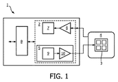
図1から、本発明の好適な実施形態による動き検出用の統合RFトランシーバデバイス2とRFコイル4とを有する前置増幅器プリント回路基板1を概略的に見ることができる。これは、磁気共鳴画像の生成用のRF信号を送信及び/又は受信するRFコイル4を有するRFコイル装置である。RFコイル装置は、磁気共鳴画像の生成用のRF信号の送信及び/又は受信と同時に、患者の動きによる動き信号を感知することを可能にする、検査中の患者の組織と相互作用するために適合するRF送信信号を送信及び受信するための、追加のRFセンサを備える。RFトランシーバ2のアンテナ3は、RFコイル4に統合されているが、プリント回路基板1上に配置することもできる。RFコイル4自体もまた、マルチ共振デザインでは、RFトランシーバデバイス2によってアンテナデバイスとして使用することができる。プリント回路基板1は、デジタル変調器9及び増幅器10を含むレーダ及びRFセンサ5を含み、そこから信号がアンテナ3に供給される。RFコイル4によって受信された信号は、前置増幅器6に供給され、更にデジタイザ及びコンプレッサ7に供給される。I/O機能はデジタルインターフェイス8によって実現される。
From FIG. 1, a preamplifier printed circuit board 1 having an integrated
図2は、本発明の別の好適な実施形態による動き検出用の統合RFトランシーバデバイス2’を有する前置増幅器プリント回路基板を概略的に示す。全体的なデザインは、図1に示すデザインと類似し、同様のデバイスは同様の参照符号で参照される。ただし、ここでは、MRI帯域外又はデジタルスペクトラム拡散信号である搬送波信号が生成される。スペクトラム拡散信号は、デコリレータ11を介してMRI信号から除去される。RFコイル4は、MRI及び動き検出用の追加のRF信号に同時に使用される。
FIG. 2 schematically illustrates a preamplifier printed circuit board with an integrated RF transceiver device 2'for motion detection according to another preferred embodiment of the invention. The overall design is similar to the design shown in FIG. 1, similar devices are referenced with similar reference numerals. However, here, a carrier signal that is out of the MRI band or is a digital spread spectrum signal is generated. The spread spectrum signal is removed from the MRI signal via the
図3は、本発明の好適な実施形態による統合RF動き検出器を有するRFコイルアレイを概略的に示す。個々のコイル21はそれぞれ局所的動き検出デバイス22を備えている。動き検出デバイス22は、患者の組織23の動き、即ち、患者の内臓(心臓、肝臓)又は患者の体表面の動きを感知する。動き感知フィールドは、参照符号24で示されている。個々のコイル素子間の反射波又はクロストークのいずれかが、更なる処理に使用される。
FIG. 3 schematically shows an RF coil array with an integrated RF motion detector according to a preferred embodiment of the invention. Each
図4は、本発明の更に好適な実施形態、即ち、a)アンテナアレイ41、b)ダイポール42及びc)スパイラルビバルディデザイン43による統合RF動き検出器アンテナを有するRFコイル4を概略的に示す。図5は、本発明の別の好適な実施形態による統合分散スタブアンテナ44を有するRFコイルアンテナ4を概略的に示す。
FIG. 4 schematically shows a more preferred embodiment of the invention, ie, an
本発明の好適な実施形態によれば、図6に概略的に示すMRIシステム60は、深層学習機能を備えた機械学習モジュール51を含む。図6は更に、MRIシステム60のMRIボア54内でのMRI検査中に患者53を保持する患者ベッド52を示す。患者ベッド52は、患者53の組織と相互作用するRF送信信号を送信することで、磁気共鳴画像の生成用のRF信号の送信及び/又は受信と同時に、患者53の動きによる動き信号を感知することを可能にする幾つかのRFセンサ55を含む。RFセンサ55は、ユーザによる操作のためのMRIコンソール57と機械学習モジュール51との両方に結合された信号制御及び処理ユニット56によって制御される。機械学習モジュール51は、感知された動き信号と、磁気共鳴画像の生成用のRF信号とを受信する。
According to a preferred embodiment of the present invention, the
機械学習モジュール51は、RFセンサ55の動作条件の関連するセンサ属性、例えば、
−心臓の動き
−臓器の動き(呼吸)
−体及び四肢の動き
−患者の姿勢
−患者の体重
−電気的パラメータ(誘電率及び負荷)
−反射パワー
−コイル負荷条件
を特定する。
The
-Movement of the heart-Movement of organs (breathing)
-Body and limb movements-Patient posture-Patient weight-Electrical parameters (dielectric constant and load)
-Reflected power-Specify coil load conditions.
信号制御及び処理ユニット56は、RFセンサ係数設定を継続的に修正し、また、動作条件が変化するにつれて、センサ、周波数及びアンテナの選択といった他のパラメータを修正する。機械学習モジュール51は、現在の動作条件をモニタリングし、突然の変化に応答して、同様の条件下で前にうまくいった過去の係数を復元する。
The signal control and
うまくいった係数設定は、測定された動作条件から導出された多次元属性ベクトルを使用してインデックスが付けられたリストに保存される。配列構造のルックアップテーブルとは異なり、リストは要素を自動的に生成する。より多くの動作条件を経験すると成長し、隣接する要素が冗長であると認識されると縮小するため、リストのサイズは動的である。 Successful coefficient settings are stored in an indexed list using a multidimensional attribute vector derived from the measured operating conditions. Unlike array-structured lookup tables, lists automatically generate elements. The size of the list is dynamic because it grows as it experiences more operating conditions and shrinks when adjacent elements are perceived to be redundant.
本発明を、図面及び前述の説明で詳細に例示及び説明してきたが、このような例示及び説明は、例示的と見なされるべきであり、限定的ではない。本発明は、開示された実施形態に限定されない。開示された実施形態に対する他の変形は、図面、開示及び添付の特許請求の範囲の検討から、請求項に係る発明を実施する際に当業者によって理解及び達成される。特許請求の範囲において、「含む」との用語は、他の要素又はステップを除外せず、単数形は複数を除外しない。特定の手段が相互に異なる従属請求項に記載されているということだけで、これらの手段の組み合わせが有利に使用できないことを示していない。特許請求の範囲における参照符号は、範囲を限定するものとして解釈されるべきではない。更に、明確にするために、図面中のすべての要素に参照符号が付されているわけではない。 Although the present invention has been exemplified and described in detail in the drawings and the above description, such illustrations and descriptions should be considered exemplary and are not limiting. The present invention is not limited to the disclosed embodiments. Other modifications to the disclosed embodiments will be understood and achieved by one of ordinary skill in the art in carrying out the claimed invention, from the examination of the drawings, disclosure and attachment claims. In the claims, the term "contains" does not exclude other elements or steps, and the singular does not exclude the plural. The fact that certain means are described in different dependent claims does not indicate that the combination of these means cannot be used in an advantageous manner. Reference numerals in the claims should not be construed as limiting the scope. Furthermore, for clarity, not all elements in the drawings are reference-coded.
1 プリント基板基盤
2 トランシーバデバイス
3 アンテナ
4 RFコイル
5 追加のRFセンサ
6 前置増幅器
7 デジタイザ及びコンプレッサ
8 デジタルインターフェイス
9 デジタル変調器
10 増幅器
11 デコリレータ
21 コイル
22 動き検出デバイス
23 組織
41 アンテナアレイ
42 ダイポール
43 スパイラルビバルディデザイン
44 分散スタブアンテナ
51 機械学習モジュール
52 患者ベッド
53 患者
54 MRIボア
55 RFセンサ
56 信号制御及び処理ユニット
57 MRIコンソール
60 MRIシステム
1 Printed
Claims (14)
磁気共鳴画像の生成用の無線周波数(RF)信号を送信及び/又は受信するRFコイルと、
前記RFコイルと接続される前置増幅器と、
前記RFコイルが前記磁気共鳴画像の生成用の前記RF信号を送信及び/又は受信するのと同時に、前記患者の組織と相互作用するためのRF送信信号を送信するための、且つ、前記患者の動きによってもたらされる動き信号を受信するための、RFセンサと
を備え、
前記RFセンサは、前記前置増幅器と一緒に配置され、
前記RFセンサは、前記RFコイルに統合されているアンテナを含み、
前記RF送信信号は、連続波レーダ信号及び/又は超広帯域レーダ信号を含む、磁気共鳴イメージングシステム。 A magnetic resonance imaging system for patient examination, wherein the magnetic resonance imaging system is
An RF coil that transmits and / or receives radio frequency (RF) signals for the generation of magnetic resonance images.
The preamplifier connected to the RF coil and
At the same time that the RF coil transmits and / or receives the RF signal for generating the magnetic resonance image, and at the same time, the RF transmission signal for interacting with the tissue of the patient is transmitted and the patient's. for receiving the motion signal provided by the motion, and RF sensor
Equipped with a,
The RF sensor is placed with the preamplifier and
The RF sensor includes an antenna integrated into the RF coil.
The RF transmission signal is a magnetic resonance imaging system including a continuous wave radar signal and / or an ultra-broadband radar signal.
前記統合RFトランシーバデバイスは更に、前記RFコイルがMRI信号及び動き検出用の追加のRF信号のために同時に使用されるように、前記MRI信号からスペクトラム拡散信号を除去するデコリレータを含む、請求項2に記載の磁気共鳴イメージングシステム。 The integrated RF transceiver device produces a carrier signal, which is a digital spread spectrum signal.
The integrated RF transceiver device is further such that said RF coil is used simultaneously for the MRI signal and additional RF signal for motion detection, comprising a decorrelator which removes a spread spectrum signal from the MRI signal, claim 2 The magnetic resonance imaging system described in.
磁気共鳴画像の生成用の追加のRF信号を送信及び/又は受信する追加のRFコイルと、
前記患者の組織と相互作用する追加のRF送信信号を送信及び受信するための、且つ、前記患者の動きによってもたらされる追加の動き信号を受信するための追加のRFセンサと、
前記追加の動き信号を処理するための追加の機械学習モジュールと
を更に含み、
受信された前記動き信号と、受信された前記追加の動き信号とをそれぞれ処理するために、前記RFセンサと前記追加のRFセンサとは、前記機械学習モジュールと前記追加の機械学習モジュールとにそれぞれ別個に接続される、請求項5に記載の磁気共鳴イメージングシステム。 The magnetic resonance imaging system is
An additional RF coil for transmitting and / or receiving additional RF signal for generating a magnetic resonance image,
For transmitting and receiving additional RF transmission signal to interact with the tissue of the patient, and the additional RF sensor for receiving the additional motion signal provided by movement of the patient,
With additional machine learning modules to process the additional motion signals
Further comprising a,
And received the motion signal, in order to process received the additional of a motion signal, respectively, wherein the RF sensor and the additional RF sensors, the machine learning module and each of said additional machine learning module are separately connected, magnetic resonance imaging system according to claim 5.
前記磁気共鳴イメージングシステムは、無線周波数(RF)コイルと、RFセンサとを含み、前記RFセンサは、前記RFコイルに統合されているアンテナを含み、前記方法は、
前記RFコイルを使用して、磁気共鳴画像の生成用のRF信号を送信及び/又は受信するステップと、
前置増幅器を使用して前記RF信号を増幅するステップと、
前記前置増幅器と一緒に配置される前記RFセンサを使用して、前記患者の組織と相互作用するRF送信信号を送信するステップと、
前記磁気共鳴画像の生成用の前記RF信号の送信及び/又は受信と同時に、前記RFセンサを使用して、前記患者の動きによる動き信号を受信するステップと、
を含み、
前記RF送信信号は、連続波レーダ信号及び/又は超広帯域レーダ信号を含む、
方法。 How to operate a magnetic resonance imaging system for patient examination
It said magnetic resonance imaging system includes a radio frequency (RF) coil, and RF sensors, the RF sensor includes an antenna that is integrated into the RF coil, the method comprising:
A step of transmitting and / or receiving an RF signal for generating a magnetic resonance image using the RF coil.
The step of amplifying the RF signal using a preamplifier, and
Using the RF sensor , which is placed with the preamplifier, to transmit an RF transmission signal that interacts with the patient's tissue.
A step wherein at the same time as the transmission and / or reception of the RF signal for generating a magnetic resonance image, which uses the RF sensor, receives a motion signal by the movement of the patient,
Including
The RF transmission signal includes a continuous wave radar signal and / or an ultra-wideband radar signal .
Method.
前記RFコイルを使用して、磁気共鳴画像の生成用のRF信号を送信及び/又は受信させ、
前置増幅器と一緒に配置される前記RFセンサを使用して、前記患者の組織と相互作用するRF送信信号を送信させ、
前記磁気共鳴画像の生成用の前記RF信号の送信及び/又は受信と同時に、前記RFセンサを使用して、前記患者の動きによる動き信号を受信させる
命令が格納されており、
前記RF送信信号は、連続波レーダ信号及び/又は超広帯域レーダ信号を含む、非一時的コンピュータ可読媒体。 A non-temporary computer-readable medium for controlling the operation of a magnetic resonance imaging system for patient examination , including a radio frequency ( RF ) coil and an RF sensor , the RF sensor integrated into the RF coil. When the non-temporary computer-readable medium, including the antenna, is run on the processor, the processor.
The RF coil is used to transmit and / or receive an RF signal for the generation of a magnetic resonance image.
The RF sensor, which is placed with the preamplifier, is used to transmit an RF transmit signal that interacts with the patient's tissue.
At the same time as the transmission and / or reception of the RF signal for generating the magnetic resonance image, the RF sensor is used to receive the motion signal due to the movement of the patient.
Instructions are stored and
The RF transmit signal is a non-transient computer-readable medium including a continuous wave radar signal and / or an ultra-wideband radar signal.
前記統合RFトランシーバデバイスを使用して、デジタルスペクトラム拡散信号である搬送波信号を生成するステップ Using the integrated RF transceiver device to generate a carrier signal, which is a digital spread spectrum signal.
を更に含む、請求項8に記載の方法。 8. The method of claim 8.
を更に含む、請求項13に記載の方法。 13. The method of claim 13.
Applications Claiming Priority (3)
| Application Number | Priority Date | Filing Date | Title |
|---|---|---|---|
| EP17202078.6 | 2017-11-16 | ||
| EP17202078.6A EP3486672A1 (en) | 2017-11-16 | 2017-11-16 | Magnetic resonance imaging system with rf motion detection |
| PCT/EP2018/080825 WO2019096707A1 (en) | 2017-11-16 | 2018-11-09 | Magnetic resonance imaging system with rf motion detection |
Publications (3)
| Publication Number | Publication Date |
|---|---|
| JP2021503337A JP2021503337A (en) | 2021-02-12 |
| JP2021503337A5 JP2021503337A5 (en) | 2021-10-21 |
| JP6980917B2 true JP6980917B2 (en) | 2021-12-15 |
Family
ID=60331504
Family Applications (1)
| Application Number | Title | Priority Date | Filing Date |
|---|---|---|---|
| JP2020527099A Active JP6980917B2 (en) | 2017-11-16 | 2018-11-09 | Magnetic resonance imaging system with RF motion detection |
Country Status (5)
| Country | Link |
|---|---|
| US (1) | US11181600B2 (en) |
| EP (2) | EP3486672A1 (en) |
| JP (1) | JP6980917B2 (en) |
| CN (1) | CN111480089B (en) |
| WO (1) | WO2019096707A1 (en) |
Families Citing this family (6)
| Publication number | Priority date | Publication date | Assignee | Title |
|---|---|---|---|---|
| EP3742184A1 (en) * | 2019-05-20 | 2020-11-25 | Koninklijke Philips N.V. | Multi-channel pilot tone motion detection |
| EP3741293B1 (en) * | 2019-05-24 | 2021-06-30 | Siemens Healthcare GmbH | Method and system for measuring blood flow |
| US20210121094A1 (en) * | 2019-10-25 | 2021-04-29 | Hyperfine Research, Inc. | Systems and methods for detecting patient motion during magnetic resonance imaging |
| EP3816647A1 (en) | 2019-10-28 | 2021-05-05 | Siemens Healthcare GmbH | Method and system for monitoring a motion of a subject, and corresponding computer program product |
| US11925419B2 (en) | 2020-12-30 | 2024-03-12 | Shanghai United Imaging Healthcare Co., Ltd. | Systems and methods for position determination |
| CN112798995B (en) * | 2020-12-30 | 2022-11-25 | 上海联影医疗科技股份有限公司 | Motion monitoring method applied to magnetic resonance imaging and magnetic resonance imaging system |
Family Cites Families (20)
| Publication number | Priority date | Publication date | Assignee | Title |
|---|---|---|---|---|
| US4712560A (en) | 1985-08-09 | 1987-12-15 | General Electric Company | Apparatus and method of acquiring physiological gating signals for magnetic resonance imaging of moving objects |
| JPH02180404A (en) * | 1988-12-30 | 1990-07-13 | Nippon Mektron Ltd | Plane receiving antenna equipment |
| US20080039718A1 (en) * | 2006-08-12 | 2008-02-14 | Philometron | Platform for detection of tissue structure change |
| GB2449081B (en) * | 2007-05-08 | 2009-03-18 | Laerdal Medical As | Breathing detection |
| DE102009041261A1 (en) * | 2009-09-11 | 2011-03-31 | Siemens Aktiengesellschaft | Combined imaging system comprising a magnetic resonance system and a UWB radar |
| CN101785672B (en) * | 2010-01-29 | 2011-08-31 | 重庆大学 | Breast tumor diagnosis system based on magnetic resonance spectrum imaging |
| US20120095322A1 (en) | 2010-09-08 | 2012-04-19 | Tsekos Nikolaos V | Devices, systems and methods for multimodal biosensing and imaging |
| CN103649767B (en) | 2011-07-04 | 2016-09-21 | 皇家飞利浦有限公司 | There is the magnetic resonance imaging system of multichannel impedance matching network |
| EP2863795B1 (en) * | 2012-06-21 | 2023-05-31 | Koninklijke Philips N.V. | Magnetic resonance examination system with motion detection |
| DE102012216303A1 (en) * | 2012-09-13 | 2014-03-13 | Siemens Aktiengesellschaft | Magnetic resonance recording unit and a magnetic resonance device with the magnetic resonance recording unit |
| US10073154B2 (en) | 2013-03-13 | 2018-09-11 | Koninklijke Philips N.V. | Multi-element RF transmit coil for magnetic resonance imaging |
| DE102013212819A1 (en) * | 2013-07-01 | 2015-01-08 | Siemens Aktiengesellschaft | Radar system for medical use |
| KR101723497B1 (en) * | 2013-08-30 | 2017-04-05 | 지멘스 악티엔게젤샤프트 | Method for determining the respiratory rate of a living being, respiratory rate determination system and magnetic resonance imaging device |
| EP3084462B1 (en) * | 2013-12-20 | 2019-05-01 | Koninklijke Philips N.V. | Breath-hold detection for magnetic resonance imaging |
| DE102014207124A1 (en) * | 2014-04-14 | 2015-10-15 | Siemens Aktiengesellschaft | Medical imaging device |
| DE102014208537A1 (en) * | 2014-05-07 | 2015-11-12 | Siemens Aktiengesellschaft | A magnetic resonance device with a motion detection unit and a method for detecting a movement of a patient during a magnetic resonance examination |
| DE102015200510A1 (en) * | 2015-01-15 | 2016-07-21 | Siemens Healthcare Gmbh | motion sensor |
| KR101688434B1 (en) * | 2015-08-25 | 2016-12-23 | 재단법인대구경북과학기술원 | Image acquisition apparatus and method |
| DE102015224158A1 (en) * | 2015-12-03 | 2017-06-08 | Siemens Healthcare Gmbh | Signal transmitter for pilot tone navigation |
| EP3633401A1 (en) * | 2018-10-04 | 2020-04-08 | Siemens Healthcare GmbH | Prevention of compensating a wrongly detected motion in mri |
-
2017
- 2017-11-16 EP EP17202078.6A patent/EP3486672A1/en not_active Withdrawn
-
2018
- 2018-11-09 CN CN201880081156.3A patent/CN111480089B/en active Active
- 2018-11-09 EP EP18800164.8A patent/EP3710846A1/en active Pending
- 2018-11-09 JP JP2020527099A patent/JP6980917B2/en active Active
- 2018-11-09 WO PCT/EP2018/080825 patent/WO2019096707A1/en unknown
- 2018-11-09 US US16/763,589 patent/US11181600B2/en active Active
Also Published As
| Publication number | Publication date |
|---|---|
| US20200284863A1 (en) | 2020-09-10 |
| CN111480089A (en) | 2020-07-31 |
| CN111480089B (en) | 2023-07-07 |
| JP2021503337A (en) | 2021-02-12 |
| EP3486672A1 (en) | 2019-05-22 |
| EP3710846A1 (en) | 2020-09-23 |
| US11181600B2 (en) | 2021-11-23 |
| WO2019096707A1 (en) | 2019-05-23 |
Similar Documents
| Publication | Publication Date | Title |
|---|---|---|
| JP6980917B2 (en) | Magnetic resonance imaging system with RF motion detection | |
| CN104422915B (en) | The B0 homogenization method adapted to shim coil for the patient of magnetic resonance system | |
| US9626777B2 (en) | Method and apparatus to generate image data | |
| US9588203B2 (en) | Apparatus, method and computer-accessible medium for determination of electrical properties of tissues and materials using multiple radio frequency measurements | |
| KR101663229B1 (en) | Magnetic resonance imaging apparatus and imaging method for magnetic resonance image thereof | |
| US20200367765A1 (en) | Method and system for measuring blood flow | |
| US20100106008A1 (en) | Magnetic resonance imaging system and method | |
| US10302713B2 (en) | Method and magnetic resonance apparatus for determining absolute receive sensitivity maps for reception coils | |
| US10444314B2 (en) | Magnetic resonance imaging apparatus and method for acquiring under-sampled MR signal | |
| Dietrich et al. | 3D Free‐breathing multichannel absolute Mapping in the human body at 7T | |
| US9395430B2 (en) | Method of generating magnetic resonance image, method of acquiring phase information of phase contrast image, method of acquiring phase information of susceptibility weighted image, and apparatus for generating magnetic resonance image | |
| CN113841060A (en) | Multi-channel pilot tone motion detection | |
| JP6791759B2 (en) | System for spiral volume imaging | |
| KR101630762B1 (en) | Apparatus and method for generating magnetic resonance image | |
| EP3756536A1 (en) | Medical imaging system | |
| US10429479B2 (en) | Rapid measurement of perfusion using optimized magnetic resonance fingerprinting | |
| US8165377B2 (en) | System and method for determining a cardiac axis | |
| JP2003325479A (en) | Method of correcting imaging data | |
| KR101755600B1 (en) | Rf receiving coil unit for mr imaging device | |
| US11249154B2 (en) | Magnetic resonance imaging apparatus | |
| KR102092908B1 (en) | Magnetic Resonance Imaging Apparatus for Correcting Respiratory Movement | |
| KR102257963B1 (en) | Apparatus for Detecting Respiratory Interval Using Histogram Cumulative Distribution of Respiratory Gating Signal | |
| JP2022024661A (en) | Image processing device, image processing method, and program | |
| JP2004248823A (en) | Magnetic resonance imaging apparatus |
Legal Events
| Date | Code | Title | Description |
|---|---|---|---|
| A521 | Request for written amendment filed |
Free format text: JAPANESE INTERMEDIATE CODE: A523 Effective date: 20210908 |
|
| A621 | Written request for application examination |
Free format text: JAPANESE INTERMEDIATE CODE: A621 Effective date: 20210908 |
|
| A871 | Explanation of circumstances concerning accelerated examination |
Free format text: JAPANESE INTERMEDIATE CODE: A871 Effective date: 20210908 |
|
| TRDD | Decision of grant or rejection written | ||
| A01 | Written decision to grant a patent or to grant a registration (utility model) |
Free format text: JAPANESE INTERMEDIATE CODE: A01 Effective date: 20211019 |
|
| A61 | First payment of annual fees (during grant procedure) |
Free format text: JAPANESE INTERMEDIATE CODE: A61 Effective date: 20211117 |
|
| R150 | Certificate of patent or registration of utility model |
Ref document number: 6980917 Country of ref document: JP Free format text: JAPANESE INTERMEDIATE CODE: R150 |