JP6980704B2 - Digital printing process - Google Patents
Digital printing process Download PDFInfo
- Publication number
- JP6980704B2 JP6980704B2 JP2018562655A JP2018562655A JP6980704B2 JP 6980704 B2 JP6980704 B2 JP 6980704B2 JP 2018562655 A JP2018562655 A JP 2018562655A JP 2018562655 A JP2018562655 A JP 2018562655A JP 6980704 B2 JP6980704 B2 JP 6980704B2
- Authority
- JP
- Japan
- Prior art keywords
- itm
- layer
- degrees
- silicone
- ink
- Prior art date
- Legal status (The legal status is an assumption and is not a legal conclusion. Google has not performed a legal analysis and makes no representation as to the accuracy of the status listed.)
- Active
Links
Images


Classifications
-
- B—PERFORMING OPERATIONS; TRANSPORTING
- B41—PRINTING; LINING MACHINES; TYPEWRITERS; STAMPS
- B41J—TYPEWRITERS; SELECTIVE PRINTING MECHANISMS, i.e. MECHANISMS PRINTING OTHERWISE THAN FROM A FORME; CORRECTION OF TYPOGRAPHICAL ERRORS
- B41J2/00—Typewriters or selective printing mechanisms characterised by the printing or marking process for which they are designed
- B41J2/005—Typewriters or selective printing mechanisms characterised by the printing or marking process for which they are designed characterised by bringing liquid or particles selectively into contact with a printing material
- B41J2/01—Ink jet
-
- B—PERFORMING OPERATIONS; TRANSPORTING
- B41—PRINTING; LINING MACHINES; TYPEWRITERS; STAMPS
- B41J—TYPEWRITERS; SELECTIVE PRINTING MECHANISMS, i.e. MECHANISMS PRINTING OTHERWISE THAN FROM A FORME; CORRECTION OF TYPOGRAPHICAL ERRORS
- B41J2/00—Typewriters or selective printing mechanisms characterised by the printing or marking process for which they are designed
- B41J2/005—Typewriters or selective printing mechanisms characterised by the printing or marking process for which they are designed characterised by bringing liquid or particles selectively into contact with a printing material
- B41J2/0057—Typewriters or selective printing mechanisms characterised by the printing or marking process for which they are designed characterised by bringing liquid or particles selectively into contact with a printing material where an intermediate transfer member receives the ink before transferring it on the printing material
-
- B—PERFORMING OPERATIONS; TRANSPORTING
- B41—PRINTING; LINING MACHINES; TYPEWRITERS; STAMPS
- B41M—PRINTING, DUPLICATING, MARKING, OR COPYING PROCESSES; COLOUR PRINTING
- B41M5/00—Duplicating or marking methods; Sheet materials for use therein
-
- B—PERFORMING OPERATIONS; TRANSPORTING
- B41—PRINTING; LINING MACHINES; TYPEWRITERS; STAMPS
- B41M—PRINTING, DUPLICATING, MARKING, OR COPYING PROCESSES; COLOUR PRINTING
- B41M5/00—Duplicating or marking methods; Sheet materials for use therein
- B41M5/025—Duplicating or marking methods; Sheet materials for use therein by transferring ink from the master sheet
- B41M5/0256—Duplicating or marking methods; Sheet materials for use therein by transferring ink from the master sheet the transferable ink pattern being obtained by means of a computer driven printer, e.g. an ink jet or laser printer, or by electrographic means
-
- B—PERFORMING OPERATIONS; TRANSPORTING
- B41—PRINTING; LINING MACHINES; TYPEWRITERS; STAMPS
- B41M—PRINTING, DUPLICATING, MARKING, OR COPYING PROCESSES; COLOUR PRINTING
- B41M5/00—Duplicating or marking methods; Sheet materials for use therein
- B41M5/025—Duplicating or marking methods; Sheet materials for use therein by transferring ink from the master sheet
- B41M5/03—Duplicating or marking methods; Sheet materials for use therein by transferring ink from the master sheet by pressure
-
- C—CHEMISTRY; METALLURGY
- C09—DYES; PAINTS; POLISHES; NATURAL RESINS; ADHESIVES; COMPOSITIONS NOT OTHERWISE PROVIDED FOR; APPLICATIONS OF MATERIALS NOT OTHERWISE PROVIDED FOR
- C09D—COATING COMPOSITIONS, e.g. PAINTS, VARNISHES OR LACQUERS; FILLING PASTES; CHEMICAL PAINT OR INK REMOVERS; INKS; CORRECTING FLUIDS; WOODSTAINS; PASTES OR SOLIDS FOR COLOURING OR PRINTING; USE OF MATERIALS THEREFOR
- C09D11/00—Inks
- C09D11/30—Inkjet printing inks
- C09D11/32—Inkjet printing inks characterised by colouring agents
- C09D11/322—Pigment inks
-
- C—CHEMISTRY; METALLURGY
- C09—DYES; PAINTS; POLISHES; NATURAL RESINS; ADHESIVES; COMPOSITIONS NOT OTHERWISE PROVIDED FOR; APPLICATIONS OF MATERIALS NOT OTHERWISE PROVIDED FOR
- C09D—COATING COMPOSITIONS, e.g. PAINTS, VARNISHES OR LACQUERS; FILLING PASTES; CHEMICAL PAINT OR INK REMOVERS; INKS; CORRECTING FLUIDS; WOODSTAINS; PASTES OR SOLIDS FOR COLOURING OR PRINTING; USE OF MATERIALS THEREFOR
- C09D11/00—Inks
- C09D11/30—Inkjet printing inks
- C09D11/38—Inkjet printing inks characterised by non-macromolecular additives other than solvents, pigments or dyes
-
- C—CHEMISTRY; METALLURGY
- C09—DYES; PAINTS; POLISHES; NATURAL RESINS; ADHESIVES; COMPOSITIONS NOT OTHERWISE PROVIDED FOR; APPLICATIONS OF MATERIALS NOT OTHERWISE PROVIDED FOR
- C09D—COATING COMPOSITIONS, e.g. PAINTS, VARNISHES OR LACQUERS; FILLING PASTES; CHEMICAL PAINT OR INK REMOVERS; INKS; CORRECTING FLUIDS; WOODSTAINS; PASTES OR SOLIDS FOR COLOURING OR PRINTING; USE OF MATERIALS THEREFOR
- C09D11/00—Inks
- C09D11/54—Inks based on two liquids, one liquid being the ink, the other liquid being a reaction solution, a fixer or a treatment solution for the ink
-
- B—PERFORMING OPERATIONS; TRANSPORTING
- B41—PRINTING; LINING MACHINES; TYPEWRITERS; STAMPS
- B41M—PRINTING, DUPLICATING, MARKING, OR COPYING PROCESSES; COLOUR PRINTING
- B41M1/00—Inking and printing with a printer's forme
- B41M1/06—Lithographic printing
-
- B—PERFORMING OPERATIONS; TRANSPORTING
- B41—PRINTING; LINING MACHINES; TYPEWRITERS; STAMPS
- B41M—PRINTING, DUPLICATING, MARKING, OR COPYING PROCESSES; COLOUR PRINTING
- B41M5/00—Duplicating or marking methods; Sheet materials for use therein
- B41M5/0011—Pre-treatment or treatment during printing of the recording material, e.g. heating, irradiating
- B41M5/0017—Application of ink-fixing material, e.g. mordant, precipitating agent, on the substrate prior to printing, e.g. by ink-jet printing, coating or spraying
-
- B—PERFORMING OPERATIONS; TRANSPORTING
- B41—PRINTING; LINING MACHINES; TYPEWRITERS; STAMPS
- B41M—PRINTING, DUPLICATING, MARKING, OR COPYING PROCESSES; COLOUR PRINTING
- B41M5/00—Duplicating or marking methods; Sheet materials for use therein
- B41M5/0041—Digital printing on surfaces other than ordinary paper
Landscapes
- Chemical & Material Sciences (AREA)
- Engineering & Computer Science (AREA)
- Life Sciences & Earth Sciences (AREA)
- Materials Engineering (AREA)
- Wood Science & Technology (AREA)
- Organic Chemistry (AREA)
- Chemical Kinetics & Catalysis (AREA)
- General Engineering & Computer Science (AREA)
- Ink Jet Recording Methods And Recording Media Thereof (AREA)
- Inks, Pencil-Leads, Or Crayons (AREA)
- Ink Jet (AREA)
Description
関連出願の相互参照
本開示は、2016年5月30に出願された米国特許出願整理番号第62/343,123号および2016年5月30日に出願された米国特許出願整理番号第62/343,108号の優先権を主張する。これらの特許出願は、参照することによりその全体が本願に援用される。
Cross-reference to related applications This disclosure is for US Patent Application Reference No. 62 / 343,123 filed May 30, 2016 and US Patent Application Reference No. 62/343 filed May 30, 2016. , Claim the priority of No. 108. These patent applications are incorporated herein by reference in their entirety.
本開示は、デジタル印刷プロセス、水性処理調合物、および関連するキットならびにシステムに関する。 The present disclosure relates to digital printing processes, aqueous treatment formulations, and related kits and systems.
以下の特許広報は、潜在的に関連する背景資料を提供し、これらの特許広報のすべては、参照することによりその全体が援用される。
WO/2017/009722(2016年5月25日に出願されたPCT/IB2016/053049の広報)、
WO/2016/166690(2016年4月4日に出願されたPCT/IB2016/052120の広報)、
WO/2016/151462(2016年3月20日に出願されたPCT/IB2016/051560の広報)、
WO/2016/113698(2016年1月14日に出願されたPCT/IB2016/050170の広報)、
WO/2015/110988(2015年1月22日に出願されたPCT/IB2015/050501の広報)、
WO/2015/036812(2013年9月12日に出願されたPCT/IB2013/002571の広報)、
WO/2015/036864(2014年9月11日に出願されたPCT/IB2014/002366の広報)、
WO/2015/036865(2014年9月11日に出願されたPCT/IB2014/002395の広報)、
WO/2015/036906(2014年9月12日に出願されたPCT/IB2014/064277の広報)、
WO/2013/136220(2013年3月5日に出願されたPCT/IB2013/051719の広報)、
WO/2013/132419(2013年3月5日に出願されたPCT/IB2013/051717の広報)、
WO/2013/132424(2013年3月5日に出願されたPCT/IB2013/051727の広報)、
WO/2013/132420(2013年3月5日に出願されたPCT/IB2013/051718の広報)、
WO/2013/132439(2013年3月5日に出願されたPCT/IB2013/051755の広報)、
WO/2013/132438(2013年3月5日に出願されたPCT/IB2013/051751の広報)、
WO/2013/132418(2013年3月5日に出願されたPCT/IB2013/051716の広報)、
WO/2013/132356(2013年1月10日に出願されたPCT/IB2013/050245の広報)、
WO/2013/132345(2013年3月5日に出願されたPCT/IB2013/000840の広報)、
WO/2013/132339(2013年3月5日に出願されたPCT/IB2013/000757の広報)、
WO/2013/132343(2013年3月5日に出願されたPCT/IB2013/000822の広報)、
WO/2013/132340(2013年3月5日に出願されたPCT/IB2013/000782の広報)、
WO/2013/132432(2013年3月5日に出願されたPCT/IB2013/051743の広報)。
The following patent publicity provides potentially relevant background material, and all of these patent publicity are incorporated by reference in their entirety.
WO / 2017/09722 (Public relations of PCT / IB2016 / 053049 filed on May 25, 2016),
WO / 2016/16669 (Public relations of PCT / IB2016 / 052120 filed on April 4, 2016),
WO / 2016/151462 (Public relations of PCT / IB2016 / 051560 filed on March 20, 2016),
WO / 2016/113698 (Public relations of PCT / IB2016 / 050170 filed on January 14, 2016),
WO / 2015/11988 (Public relations of PCT / IB2015 / 055001 filed on January 22, 2015),
WO / 2015/036812 (Public relations of PCT / IB2013 / 002571 filed on September 12, 2013),
WO / 2015/036864 (Public relations of PCT / IB2014 / 00266 filed on September 11, 2014),
WO / 2015/036865 (Public relations of PCT / IB2014 / 002395 filed on September 11, 2014),
WO / 2015/03696 (Public relations of PCT / IB2014 / 064277 filed on September 12, 2014),
WO / 2013/136220 (Public relations of PCT / IB2013 / 051719 filed on March 5, 2013),
WO / 2013/132419 (Public relations of PCT / IB2013 / 051717 filed on March 5, 2013),
WO / 2013/132424 (Public relations of PCT / IB2013 / 051727 filed on March 5, 2013),
WO / 2013/132420 (Public relations of PCT / IB2013 / 051718 filed on March 5, 2013),
WO / 2013/132439 (Public relations of PCT / IB2013 / 051755 filed on March 5, 2013),
WO / 2013/132438 (Public relations of PCT / IB2013 / 051751 filed on March 5, 2013),
WO / 2013/132418 (Public relations for PCT / IB2013 / 051716 filed on March 5, 2013),
WO / 2013/132356 (Public relations of PCT / IB2013 / 050245 filed on January 10, 2013),
WO / 2013/132345 (Public relations of PCT / IB2013 / 00840 filed on March 5, 2013),
WO / 2013/132339 (Public relations of PCT / IB2013 / 00757 filed on March 5, 2013),
WO / 2013/132343 (Public relations of PCT / IB2013 / 00822 filed on March 5, 2013),
WO / 2013/132340 (Public relations of PCT / IB 2013/000782 filed on March 5, 2013),
WO / 2013/132432 (Public relations of PCT / IB2013 / 051743 filed on March 5, 2013).
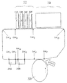
図1は、インク画像が中間転写部材(ITM)に堆積される前にITMが前処理される従来型印刷処理のフローチャートである。ステップS1では、ITM表面を前処理するために処理溶液が疎水性ITMの表面に塗布される。ステップS9では、水性インクの液滴が前処理済みITM表面上にインクジェットされ、それによりインク画像が形成される。ステップS13では、インク画像がITM表面上で乾燥する。ステップS17では、乾燥されたインク画像は基板上に転送される。 FIG. 1 is a flowchart of a conventional printing process in which an ITM is preprocessed before an ink image is deposited on an intermediate transfer member (ITM). In step S1, a treatment solution is applied to the surface of the hydrophobic ITM to pretreat the surface of the ITM. In step S9, droplets of the water-based ink are inkjet onto the pretreated ITM surface, thereby forming an ink image. In step S13, the ink image dries on the ITM surface. In step S17, the dried ink image is transferred onto the substrate.
本発明の様々な実施形態は、改善された印刷処理に、改善されたITM(またはITMの部分)に、および、水性インクの液滴を堆積する前にITMを前処理するために使用される改善された組成物に、関する。 Various embodiments of the invention are used for improved print processing, to improved ITM (or portion of ITM), and to pretreat ITM prior to depositing droplets of water-based ink. With respect to the improved composition.
本発明の様々な態様は、a.以下の特性すなわち、(i)シリコーン系剥離層表面上に堆積された蒸留水滴の後退接触角が最大60度であること、および、(ii)シリコーン系剥離層表面上に堆積された蒸留水滴の10秒動的接触角(DCA)が最大108度であること、のうちの少なくとも1つを満足するよう十分な親水性を示すシリコーン系剥離層表面を含む中間転写部材(ITM)を提供することと、b.i.摂氏25度において少なくとも5%の水溶解度を有する少なくとも3重量%の第四級アンモニウム塩、ii.摂氏25度において少なくとも5%の水溶解度を有する少なくとも1重量%の少なくとも1つの水溶性ポリマー、および、iii.水を含むキャリア液体であって、該水は、水性処理調合物の少なくとも65重量%を占める、キャリア液体、を含む水性処理調合物であって、下の特性、すなわち、i.摂氏25度において20〜40ダイン/cmの範囲内の静的表面張力、ii.少なくとも10cPである摂氏25度粘性係数、および、iii.重量で最大8:1の摂氏60度蒸発負荷、を有する、水性処理調合物を提供することと、c.水性処理調合物をITMのシリコーン系剥離層表面に塗布して、最大0.8μmの厚さを有する湿潤処理層を前述のシリコーン系剥離層表面上に形成することと、d.湿潤処理層に乾燥処理を施して、湿潤処理層から、シリコーン系剥離層表面上に乾燥処理薄膜を形成することと、e.水性インクの液滴を乾燥処理薄膜上に堆積して、シリコーン系剥離層表面の剥離層表面上にインク画像を形成することと、f.インク画像を乾燥させてシリコーン系剥離層表面上に残留インク画像を残すことと、g.ITMと印刷基板との間の加圧接触により、残留インク画像を印刷基板上に転送することと、を含む、印刷方法に関する。 Various aspects of the invention are described in a. The following characteristics, that is, (i) the receding contact angle of the distilled water droplet deposited on the surface of the silicone-based peeling layer is up to 60 degrees, and (ii) the distilled water droplet deposited on the surface of the silicone-based peeling layer. Provided is an intermediate transfer member (ITM) containing a silicone-based release layer surface exhibiting sufficient hydrophilicity to satisfy at least one of a 10-second dynamic contact angle (DCA) of up to 108 degrees. And b. i. At least 3% by weight quaternary ammonium salt, ii., With a water solubility of at least 5% at 25 degrees Celsius. At least 1% by weight of at least one water-soluble polymer having a water solubility of at least 5% at 25 degrees Celsius, and iii. A carrier liquid comprising water, wherein the water is an aqueous treatment formulation comprising a carrier liquid, which accounts for at least 65% by weight of the aqueous treatment formulation, and has the following properties, i.e., i. Static surface tension in the range of 20-40 dynes / cm at 25 degrees Celsius, ii. A viscosity coefficient of 25 degrees Celsius, which is at least 10 cP, and iii. To provide an aqueous treatment formulation having a 60 degree Celsius evaporation load, up to 8: 1 by weight, and c. The aqueous treatment formulation was applied to the surface of the silicone-based release layer of ITM to form a wet-treated layer having a maximum thickness of 0.8 μm on the surface of the above-mentioned silicone-based release layer. The wet-treated layer is subjected to a drying treatment to form a dry-treated thin film on the surface of the silicone-based release layer from the wet-treated layer, and e. Droplets of the water-based ink are deposited on the dry-treated thin film to form an ink image on the surface of the release layer on the surface of the silicone-based release layer. Drying the ink image to leave a residual ink image on the surface of the silicone-based release layer, and g. The present invention relates to a printing method including transferring a residual ink image onto a printed circuit board by pressure contact between the ITM and the printed circuit board.
本発明の様々な態様は、a.以下の特性すなわち、(i)シリコーン系剥離層表面上に堆積された蒸留水滴の後退接触角が最大60度であること、および、(ii)シリコーン系剥離層表面上に堆積された蒸留水滴の10秒動的接触角(DCA)が最大108度であること、のうちの少なくとも1つを満足するよう十分な親水性を示すシリコーン系剥離層表面を含む中間転写部材(ITM)を提供することと、b.i.摂氏25度において少なくとも5%の水溶解度を有する少なくとも3重量%の第四級アンモニウム塩、ii.摂氏25度において少なくとも5%の水溶解度を有する少なくとも1重量%の少なくとも1つの水溶性ポリマー、および、iii.水を含むキャリア液体であって、該水は、水性処理調合物の少なくとも65重量%を占める、キャリア液体、を含む水性処理調合物であって、下の特性、すなわち、i.摂氏25度において20〜40ダイン/cmの範囲内の静的表面張力、ii.少なくとも10cPである摂氏25度粘性係数、および、iii.重量で最大8:1の摂氏60度蒸発負荷、を有する、水性処理調合物を提供することと、c.水性処理調合物をITMのシリコーン系剥離層表面に塗布して、シリコーン系剥離層表面上に湿潤処理層を形成することと、d.湿潤処理層に乾燥処理を施して、湿潤処理層から、シリコーン系剥離層表面上に乾燥処理薄膜を形成することと、e.水性インクの液滴を乾燥処理薄膜上に堆積して、シリコーン系剥離層表面の剥離層表面上にインク画像を形成することと、f.インク画像を乾燥させてシリコーン系剥離層表面上に残留インク画像を残すことと、g.ITMと印刷基板との間の加圧接触により、残留インク画像を60°基板上に転送することと、を含む、印刷方法に関する。 Various aspects of the invention are described in a. The following characteristics, that is, (i) the receding contact angle of the distilled water droplet deposited on the surface of the silicone-based peeling layer is up to 60 degrees, and (ii) the distilled water droplet deposited on the surface of the silicone-based peeling layer. Provided is an intermediate transfer member (ITM) containing a silicone-based release layer surface exhibiting sufficient hydrophilicity to satisfy at least one of a 10-second dynamic contact angle (DCA) of up to 108 degrees. And b. i. At least 3% by weight quaternary ammonium salt, ii., With a water solubility of at least 5% at 25 degrees Celsius. At least 1% by weight of at least one water-soluble polymer having a water solubility of at least 5% at 25 degrees Celsius, and iii. A carrier liquid comprising water, wherein the water is an aqueous treatment formulation comprising a carrier liquid, which accounts for at least 65% by weight of the aqueous treatment formulation, and has the following properties, i.e., i. Static surface tension in the range of 20-40 dynes / cm at 25 degrees Celsius, ii. A viscosity coefficient of 25 degrees Celsius, which is at least 10 cP, and iii. To provide an aqueous treatment formulation having a 60 degree Celsius evaporation load, up to 8: 1 by weight, and c. The aqueous treatment formulation is applied to the surface of the silicone-based release layer of ITM to form a wet treatment layer on the surface of the silicone-based release layer, and d. The wet-treated layer is subjected to a drying treatment to form a dry-treated thin film on the surface of the silicone-based release layer from the wet-treated layer, and e. Droplets of the water-based ink are deposited on the dry-treated thin film to form an ink image on the surface of the release layer on the surface of the silicone-based release layer. Drying the ink image to leave a residual ink image on the surface of the silicone-based release layer, and g. The present invention relates to a printing method including transferring a residual ink image onto a 60 ° substrate by pressure contact between the ITM and the printed circuit board.
いくつかの実施形態では、提供される水性処理調合物の摂氏60度蒸発負荷は、最大で6:1、最大で5:1、最大で4:1、最大で3.5:1、または最大で3:1、および所望により、少なくとも2:1、少なくとも2.2:1、または少なくとも2.5:1である。 In some embodiments, the 60 degree Celsius evaporation load of the provided aqueous treatment formulation is up to 6: 1, up to 5: 1, up to 4: 1, up to 3.5: 1, or up to 3.5: 1. 3: 1, and optionally at least 2: 1, at least 2.2: 1, or at least 2.5: 1.
いくつかの実施形態では、提供される水性処理調合物内における該第四級アンモニウム塩の濃度は3〜15%の範囲内、該水溶性ポリマーの濃度は2.5〜10%または2.5〜8%の範囲内、摂氏60度蒸発負荷は2.5:1〜4:1の範囲内であり、該粘度は少なくとも12cPであり、所望により少なくとも14cPまたは少なくとも16cPである。 In some embodiments, the concentration of the quaternary ammonium salt in the provided aqueous treatment formulation is in the range of 3-15% and the concentration of the water-soluble polymer is 2.5-10% or 2.5. Within the range of -8%, the 60 degree Celsius evaporation load is in the range of 2.5: 1 to 4: 1, and the viscosity is at least 12 cP, optionally at least 14 cP or at least 16 cP.
いくつかの実施形態では、提供される水性処理調合物は、少なくとも6%、少なくとも7%、少なくとも8%、少なくとも9%、または少なくとも10%、および所望により、6〜40%、6〜30%、6〜20%、7〜30%、7〜20%、7〜15%、8〜25%、8〜20%、8〜15%、または8〜13%の範囲内の総界面活性剤濃度を有する。 In some embodiments, the aqueous treatment formulation provided is at least 6%, at least 7%, at least 8%, at least 9%, or at least 10%, and optionally 6-40%, 6-30%. , 6-20%, 7-30%, 7-20%, 7-15%, 8-25%, 8-20%, 8-15%, or 8-13% total surfactant concentration Has.
いくつかの実施形態では、提供される水性処理調合物内の有機溶媒の合計濃度は、最大3重量%、最大2重量%、最大1重量%、または最大0.5重量%であるか、または調合物は有機溶媒を含まない。 In some embodiments, the total concentration of organic solvent in the provided aqueous treatment formulation is up to 3% by weight, up to 2% by weight, up to 1% by weight, or up to 0.5% by weight, or The formulation does not contain organic solvents.
いくつかの実施形態では、提供される水性処理調合物内の液体吸湿剤の濃度は、最大1.5重量%、最大1重量%、最大0.5重量%、最大0.3重量%、または最大0.1重量%であるか、または水性処理調合物は液体吸湿剤を含まない。 In some embodiments, the concentration of the liquid hygroscopic agent in the provided aqueous treatment formulation is up to 1.5% by weight, up to 1% by weight, up to 0.5% by weight, up to 0.3% by weight, or Up to 0.1% by weight, or the aqueous treatment formulation is free of liquid hygroscopic agents.
いくつかの実施形態では、提供される水性処理調合物内における第四級アンモニウム塩は有機第四級アンモニウム塩である。 In some embodiments, the quaternary ammonium salt in the provided aqueous treatment formulation is an organic quaternary ammonium salt.
いくつかの実施形態では、該有機第四級アンモニウム塩の第1炭素鎖は少なくとも6炭素原子の長さを、および所望により、6〜20、6〜18、8〜20、または8〜18炭素原子の範囲内の長さを、有する。 In some embodiments, the primary carbon chain of the organic quaternary ammonium salt has a length of at least 6 carbon atoms and, optionally, 6-20, 6-18, 8-20, or 8-18 carbons. It has a length within the range of atoms.
いくつかの実施形態では、該有機第四級アンモニウム塩の第2炭素鎖は、最大3炭素原子、または最大2炭素原子の長さを有する。 In some embodiments, the secondary carbon chain of the organic quaternary ammonium salt has a length of up to 3 carbon atoms, or up to 2 carbon atoms.
いくつかの実施形態では、該有機第四級アンモニウム塩の第3炭素鎖は、最大3炭素原子、最大2炭素原子、または1炭素原子の長さを有する。 In some embodiments, the tertiary carbon chain of the organic quaternary ammonium salt has a length of up to 3 carbon atoms, up to 2 carbon atoms, or 1 carbon atom.
いくつかの実施形態では、該有機第四級アンモニウム塩は、所望により硫酸アニオンまたはリン酸アニオンを有するカチオン有機第四級アンモニウム塩である。 In some embodiments, the organic quaternary ammonium salt is a cationic organic quaternary ammonium salt having a sulfate anion or a phosphate anion, if desired.
いくつかの実施形態では、シリコーン系の剥離層表面は、以下の特性、すなわち、シリコーン系剥離層表面上に堆積された蒸留水滴の後退接触角が最大60度であることのうちの少なくとも1つを満足するにあたり十分な親水性を示す。 In some embodiments, the silicone-based exfoliation layer surface has the following properties, i.e., at least one of the following properties, i.e., that the receding contact angle of the distilled water droplets deposited on the silicone-based exfoliation layer surface is up to 60 degrees. Shows sufficient hydrophilicity to satisfy.
いくつかの実施形態では、シリコーン系剥離層表面は、以下の特性、すなわち、シリコーン系剥離層表面上に堆積された蒸留水滴の10秒動的接触角(DCA)が最大108度であることのうちの少なくとも1つを満足するにあたり十分な親水性を示す。 In some embodiments, the silicone-based exfoliation layer surface has the following properties, i.e., a 10-second dynamic contact angle (DCA) of distilled water droplets deposited on the silicone-based exfoliation layer surface is up to 108 degrees. It exhibits sufficient hydrophilicity to satisfy at least one of them.
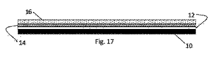
いくつかの実施形態では、提供されるITMは、支持層と、該シリコーン系剥離層表面、および、(i)該シリコーン系剥離層表面に対向し、かつ(ii)該支持造に付着された、第2表面を有する剥離層と、を含み、該剥離層は付加硬化型シリコーン物質で形成され、該剥離層の厚さは最大500マイクロメートル(μm)である。 In some embodiments, the provided ITM faces and (ii) adheres to the support layer, the surface of the silicone-based release layer, and (i) the surface of the silicone-based release layer. , A release layer having a second surface, the release layer is formed of an addition curable silicone material, and the thickness of the release layer is up to 500 micrometers (μm).
いくつかの実施形態では、提供されるITMの剥離層は、実質的に付加硬化型シリコーンからなるか、または少なくとも95重量%の付加硬化型シリコーンを含む。 In some embodiments, the stripped layer of the provided ITM consists of substantially add-curable silicone or comprises at least 95% by weight of add-on curable silicone.
いくつかの実施形態では、提供されるITMの該シリコーン系剥離層表面内の官能基は、該付加硬化型シリコーン物質の最大3重量%を構成する。 In some embodiments, the functional groups in the surface of the silicone-based release layer of the provided ITM make up up to 3% by weight of the add-curable silicone material.
いくつかの実施形態では、ポリエーテルグリコール官能化ポリジメチルシロキサンが、提供されるITMの該付加硬化型シリコーン物質に充填される。 In some embodiments, polyether glycol functionalized polydimethylsiloxane is filled in the add-curable silicone material of the provided ITM.
いくつかの実施形態では、提供されるITMの剥離層は、インク受容表面の極性基が、第2表面から離間する方向または第2表面と逆の方向を有するよう、適応される。 In some embodiments, the stripped layer of the provided ITM is adapted such that the polar groups on the ink receiving surface are oriented away from or opposite the second surface.
いくつかの実施形態では、提供されるITMのシリコーン系剥離層表面の表面疎水性は、剥離層内の硬化シリコーン物質のバルク疎水性よりも小さい。なお、表面疎水性はインク受容表面上における蒸留水液滴の後退接触角により特徴付けられ、バルク疎水性は、露出エリアを形成するために剥離層内の硬化シリコーン物質のエリアを露出させることにより形成された内側表面上に堆積された蒸留水液滴の後退接触角により特徴付けられる。 In some embodiments, the surface hydrophobicity of the silicone-based release layer surface of the provided ITM is less than the bulk hydrophobicity of the cured silicone material in the release layer. The surface hydrophobicity is characterized by the receding contact angle of the distilled water droplets on the ink receiving surface, and the bulk hydrophobicity is by exposing the area of the cured silicone material in the release layer to form an exposed area. It is characterized by the receding contact angle of the distilled water droplets deposited on the formed inner surface.
いくつかの実施形態では、水性処理調合物は、湿潤処理層の厚さが最大0.5μm、または最大0.4μmとなるよう、シリコーン系剥離層表面に塗布される。 In some embodiments, the aqueous treatment formulation is applied to the surface of the silicone-based release layer so that the wet treatment layer has a thickness of up to 0.5 μm, or up to 0.4 μm.
いくつかの実施形態では、湿潤処理層は、丸みを帯びた表面をITMに向かって、またはその逆方向に、付勢することにより、形成され、および/または、薄くされる。ここで、i.丸みを帯びた表面は最大2mm、または最大1.5mm、または最大1.25mm、または最大1mmの曲率半径を有し、および/または、ii.付勢は、少なくとも250g/cm、または少なくとも350g/cm、または少なくとも400gm/cm、および/または、最大1kg/cm、または最大750g/cm、または最大600g/cmの交差印刷方向における力密度で行われ、および/または、iii.付勢は、ITMとの間に圧力を印加することにより行われ、圧力の大きさは、少なくとも0.1バール、または少なくとも0.25バール、または少なくとも0.35バール、または少なくとも0.5バール、および所望により最大2バール、または最大1.5バール、または最大1バールである。 In some embodiments, the wet treatment layer is formed and / or thinned by urging the rounded surface towards the ITM and vice versa. Here, i. The rounded surface has a radius of curvature of up to 2 mm, or up to 1.5 mm, or up to 1.25 mm, or up to 1 mm, and / or ii. Biasing is performed at a force density of at least 250 g / cm, or at least 350 g / cm, or at least 400 gm / cm, and / or up to 1 kg / cm, or up to 750 g / cm, or up to 600 g / cm in the cross-printing direction. We and / or iii. The urging is done by applying pressure to and from the ITM, the magnitude of the pressure being at least 0.1 bar, or at least 0.25 bar, or at least 0.35 bar, or at least 0.5 bar. , And optionally up to 2 bar, or up to 1.5 bar, or up to 1 bar.
いくつかの実施形態では、湿潤処理層は、移動中のITMに対して力を直接的または間接的に印加し、それにより(i)ITMを変形させてITMに凹部を生じさせ、かつ、(ii)流れる水性処理調合物の速度勾配を確立するする、静止アプリケータおよび/または丸みを帯びた表面により、形成され、および/または薄くされる。なお、この速度勾配は、ITMに対して垂直であり、ITMと静止アプリケータとの間の間隙領域に形成される。 In some embodiments, the wet treatment layer applies force directly or indirectly to the moving ITM, thereby (i) deforming the ITM to create recesses in the ITM, and (i) ii) Formed and / or thinned by a static applicator and / or a rounded surface that establishes a velocity gradient of the flowing aqueous treatment formulation. It should be noted that this velocity gradient is perpendicular to the ITM and is formed in the gap region between the ITM and the resting applicator.
いくつかの実施形態では、速度勾配の大きさは、少なくとも106/秒または少なくとも2×106/秒である。 In some embodiments, the magnitude of the velocity gradient is at least 106 / sec or at least 2 × 10 6 / sec.
いくつかの実施形態では、水性処理調合物は、その上に湿潤処理層を形成するために少なくとも1メートル/秒、または少なくとも1.5メートル/秒、または少なくとも2メートル/秒の速度で移動中のITMの少なくとも1部分(単数または複数)に塗布される。 In some embodiments, the aqueous treatment formulation is moving at a rate of at least 1 m / sec, or at least 1.5 m / sec, or at least 2 m / sec to form a wet treatment layer on it. It is applied to at least one portion (s) of the ITM of.
いくつかの実施形態では、湿潤処理層の形成、または湿潤処理層を薄くすることは、ITMに対して垂直な速度勾配が確立され、速度勾配の大きさが少なくとも106/秒または少なくとも2×106/秒となるよう、水性処理調合物を強制的に流すことを含む。 In some embodiments, the formation of a wet treatment layer, or thinning of the wet treatment layer, establishes a velocity gradient perpendicular to the ITM and the magnitude of the velocity gradient is at least 106 / sec or at least 2 ×. It involves forcing the aqueous treatment formulation to flow to 10 6 / sec.
いくつかの実施形態では、ITMの剥離表面は、最大50、または最大45、または最大40、または最大35、または最大30、または最大25、または最大20、または最大15のショアA硬度を有する。 In some embodiments, the stripped surface of the ITM has a shore A hardness of up to 50, or up to 45, or up to 40, or up to 35, or up to 30, or up to 25, or up to 20, or up to 15.
いくつかの実施形態では、湿潤処理層の乾燥処理は、表面張力により誘導されるビーディングが阻害されて、乾燥された処理薄膜が滑らかな上方表面を有するように、水性処理調合物の粘度が十分迅速に大きくなるよう、十分迅速に行われる。 In some embodiments, the drying treatment of the wet treatment layer has a viscosity of the aqueous treatment formulation such that the beading induced by surface tension is inhibited and the dried treated thin film has a smooth upper surface. It is done quickly enough to grow fast enough.
いくつかの実施形態では、乾燥された処理薄膜の滑らかな上方表面は、最大12ナノメートル、または最大10ナノメートル、または最大9ナノメートル、または最大8ナノメートル、または最大7ナノメートル、または最大5ナノメートルの平均粗度Raにより特徴付けられる。 In some embodiments, the smooth upper surface of the dried treated thin film is up to 12 nanometers, or up to 10 nanometers, or up to 9 nanometers, or up to 8 nanometers, or up to 7 nanometers, or up to 7 nanometers. 5 is characterized by an average roughness R a of nanometers.
いくつかの実施形態では、処理溶液の乾燥は、ビーディングが防止され、かつ、最大200nm、または最大150nm、または最大120nm、または最大100nm、または最大80nm、または最大70nm、または最大60nm、または最大50nm、または最大40nm、または最大30nmの厚さを有する親水性および凝集性を有する連続的なポリマー処理薄膜が残されるよう、十分迅速に行われる。 In some embodiments, drying of the treatment solution prevents beading and is up to 200 nm, or up to 150 nm, or up to 120 nm, or up to 100 nm, or up to 80 nm, or up to 70 nm, or up to 60 nm, or up. It is done quickly enough to leave a hydrophilic and cohesive continuous polymer treated thin film with a thickness of 50 nm, or up to 40 nm, or up to 30 nm.
いくつかの実施形態では、水性インク液滴が堆積される乾燥処理薄膜の厚さは最大200nm、または最大120nm、または最大100nm、または最大80nmである。 In some embodiments, the thickness of the dry treated thin film on which the aqueous ink droplets are deposited is up to 200 nm, or up to 120 nm, or up to 100 nm, or up to 80 nm.
いくつかの実施形態では、水性インク液滴が堆積される乾燥処理薄膜の厚さは少なくとも15nm、または少なくとも20nm、または少なくとも30nmである。 In some embodiments, the thickness of the dry treated thin film on which the aqueous ink droplets are deposited is at least 15 nm, or at least 20 nm, or at least 30 nm.
いくつかの実施形態では、乾燥処理薄膜は、ITMの剥離表面の長方形全体にわたり連続的である。なお該長方形は少なくとも10cmの幅および少なくとも10メートルの長さを有する。 In some embodiments, the desiccant thin film is continuous across the rectangle of the exfoliated surface of the ITM. The rectangle has a width of at least 10 cm and a length of at least 10 meters.
いくつかの実施形態では、長方形の面積の少なくとも50%、または少なくとも75%、または少なくとも90%、または少なくとも95% 少なくとも95%、または少なくとも99%、または100%に対して、乾燥処理薄膜の厚さは、50%、または40%、または30%を越えて長方形内の平均厚さ値から逸脱しない。 In some embodiments, the thickness of the dry treated thin film is relative to at least 50%, or at least 75%, or at least 90%, or at least 95%, at least 95%, or at least 99%, or 100% of the rectangular area. No more than 50%, or 40%, or 30% deviates from the average thickness value within the rectangle.
いくつかの実施形態では、湿潤処理層の乾燥処理の間、湿潤処理層の動的粘度は、最大250ミリ秒の期間内で、少なくとも1000倍増加する。 In some embodiments, during the drying process of the wet-treated layer, the dynamic viscosity of the wet-treated layer is increased by at least 1000-fold within a period of up to 250 ms.
いくつかの実施形態では、乾燥処理薄膜の液体含有量は、最大10重量/重量%、または最大7.5重量/重量%、または最大5重量/重量%、または最大2.5重量/重量%、または最大1.5重量/重量%、または最大1重量/重量%である。 In some embodiments, the liquid content of the dry treated thin film is up to 10% by weight, or 7.5% by weight / weight, or up to 5% by weight, or up to 2.5% by weight. , Or up to 1.5% by weight /% by weight, or up to 1% by weight /% by weight.
いくつかの実施形態では、水性インクの液滴はインクジェットにより乾燥処理薄膜上に堆積される。 In some embodiments, droplets of water-based ink are deposited on the dry-treated thin film by inkjet.
いくつかの実施形態では、残留インク画像は、乾燥処理薄膜の非印刷エリアとともに、印刷基板上に転送される。 In some embodiments, the residual ink image is transferred onto the printed circuit board along with the non-printing area of the dried thin film.
いくつかの実施形態では、乾燥処理薄膜の厚さは最大120nmである。 In some embodiments, the thickness of the dried thin film is up to 120 nm.
いくつかの実施形態では、乾燥処理薄膜は、残留インク画像の転送の間、印刷エリアおよび非印刷エリアの両方において乾燥処理薄膜が完全にITMから分離して、乾燥インク画像とともに印刷基板に転送されるよう、十分な凝集性を有する。 In some embodiments, the dried thin film is transferred to the printing substrate along with the dried ink image, with the dried thin film completely separated from the ITM in both the printed and non-printed areas during the transfer of the residual ink image. It has sufficient cohesiveness so as to be.
いくつかの実施形態では、残留インク画像の転送は、最大摂氏100度または最大摂氏90度の転送温度で行われる。 In some embodiments, the transfer of the residual ink image is performed at a transfer temperature of up to 100 degrees Celsius or up to 90 degrees Celsius.
いくつかの実施形態では、水性インクの固形物(例えばナノ色素および/または樹脂)は乾燥処理薄膜のバルク中へと流動し、乾燥処理薄膜内に存在する第四級アンモニウム塩と反応(例えば結合)する(それにより、例えば液滴の展開が助長される)。 In some embodiments, the solids of the water-based ink (eg, nanodyes and / or resins) flow into the bulk of the dry-treated thin film and react (eg, bind) with the quaternary ammonium salts present in the dry-treated thin film. (It also facilitates the deployment of droplets, for example).
いくつかの実施形態では、水性インクの固形物は乾燥処理薄膜のバルク中に流動し、乾燥処理薄膜内に存在する第四級アンモニウム塩と反応し、それにより液滴の展開が助長される。 In some embodiments, the solid water-based ink flows into the bulk of the dry-treated thin film and reacts with the quaternary ammonium salts present in the dry-treated thin film, thereby facilitating the development of droplets.
いくつかの実施形態では、この方法は、i.インク基板上に存在するインクドットのインクドットセットIDSが形成され、ii.ITM上に存在する乾燥処理薄膜上に堆積された水性インク液滴の液滴複数性(droplet plurality)DPが、所与の液滴が所与の基板上に存在するインクドットを生じさせ、および/または基板上に存在するインクドットに進化するように、A.液滴複数性DPの各所与の液滴と、B.インクドットセットのそれぞれの所与の基板上に存在するインクドットと、の間に対応関係が存在するよう、インク基板上に存在するインクドットのインクドットセットIDSを形成し、iii.堆積の間、液滴複数性の液滴がITM上の乾燥処理薄膜と衝突するときはつねに、衝突する液滴の運動エネルギーが液滴を変化させ、iv.ITMの表面の上方で変形した液滴のうちの各液滴の最大衝突半径が最大衝突半径値RMAX_IMPACTを有し、v.衝突の後、基板上に存在するインクドットセットIDSの各インクドットが乾燥ドット半径RDRIED_DOT_ON_SUBSTRATEを有するよう、物理化学的な力が変形された液滴を展開させ、vi.液滴複数性の各液滴およびインクドットセットIDSの対応するインクドットに対して、A.基板上に存在する乾燥ドット半径RDRIED_DOT_ON_SUBSTRATEと、B.変形された液滴最大衝突半径値RMAX_IMPACTと、の比が少なくとも1.1となるよう、実行される。 In some embodiments, this method is i. An ink dot set IDS of ink dots existing on the ink substrate is formed, and ii. The droplet liquidity DP of water-based ink droplets deposited on a dry-treated thin film present on the ITM gives rise to ink dots in which a given droplet is present on a given substrate, and / Or to evolve into ink dots present on the substrate, A. With each given drop of the Droplet Plural DP, B.I. The ink dot set IDS of the ink dots existing on the ink substrate is formed so that there is a correspondence between the ink dots existing on each given substrate of the ink dot set, and iii. During deposition, whenever a droplet with multiple droplets collides with a dry-treated thin film on an ITM, the kinetic energy of the colliding droplets alters the droplets, iv. The maximum collision radius of each of the droplets deformed above the surface of the ITM has a maximum collision radius value R MAX_IMPACT , v. After the collision, the physicochemically transformed droplets were developed so that each ink dot of the ink dot set IDS present on the substrate had a dry dot radius R DREED_DOT_ON_SUBSTRATE. For each droplet with multiple droplets and the corresponding ink dot of the ink dot set IDS, A. The dry dot radius R DREED_DOT_ON_SUBSTRATE existing on the substrate and B.I. It is performed so that the ratio of the deformed maximum collision radius value R MAX_IMPACT to the droplet is at least 1.1.
いくつかの実施形態では、この方法は、i.ITM上に存在する乾燥処理薄膜上に堆積された液滴の液滴複数性DPが基板上に存在するインクドットのインクドットセットIDS(すなわち、上部基板表面に固定的に付着された)を生成し、液滴複数性DPの各液滴はインクドットセットIDSの異なるそれぞれの基板上に存在するインクドットに対応し、ii.液滴複数性DPの各インク液滴が、噴出パラメータにしたがって、基板上に堆積され、iii.液滴複数性DPのインク液滴の物理化学的特性とともに噴出パラメータが共同的にインクジェット紙ドット半径RDIRECT−JETTING−ONTO−INK−JET−PAPER−THEORETICALを定義し、なお、インクジェット紙ドット半径RDIRECT−JETTING−ONTO−INK−JET−PAPER−THEORETICALは、インク液滴が乾燥処理薄膜上にではなく直接的にインクジェット紙にインクジェットされた場合に取得されるインクドットの半径であり、iv.(A)インクドットセットIDSのドットの乾燥ドット半径RDRIED_DOT_ON_SUBSTRATEと、(B)インクジェット紙ドット半径RDIRECT−JETTING−ONTO−INK−JET−PAPER−THEORETICALと、の間の比が少なくとも1.1となるよう、実行される。 In some embodiments, this method is i. The droplet plural DP of the droplets deposited on the dry-treated thin film present on the ITM produces the ink dot set IDS (ie, fixedly attached to the surface of the upper substrate) of the ink dots present on the substrate. However, each droplet of the droplet plural DP corresponds to the ink dots existing on the respective substrates having different ink dot set IDSs, and ii. Each ink droplet of the droplet plural DP is deposited on the substrate according to the ejection parameter, and iii. The ejection parameters together with the physicochemical properties of the ink droplets of the droplet plural DP jointly define the inkjet paper dot radius R DIRECT-JETTING-ONTO-INK-JET-PAPER-THEORETICAL , and the inkjet paper dot radius R. DIRECT-JETTING-ONTO-INK-JET-PAPER-THEORETICAL is the radius of the ink dots obtained when the ink droplets are directly inkjetd onto the inkjet paper rather than onto the dried thin film, and iv. The ratio between (A) the dry dot radius R DREED_DOT_ON_SUBSTRATE of the dots of the ink dot set IDS and (B) the inkjet paper dot radius R DIRECT-JETTING-ONTO-INK-JET-PAPER-THEORETICAL is at least 1.1. It will be executed.
いくつかの実施形態では、インクドットセットの濃度は、少なくとも5、または少なくとも10、または少なくとも20、または少なくとも50、または少なくとも100であり、インクドットセットの各インクドットは基板上で明確に区別される。 In some embodiments, the density of the ink dot set is at least 5, or at least 10, or at least 20, or at least 50, or at least 100, and each ink dot in the ink dot set is clearly distinguished on the substrate. Ink.
いくつかの実施形態では、インクドットセットのインクドットは、印刷基板上で突起する正方形幾何学的突起物内に含まれる。インクドットセットの各インクドットは、印刷基板の表面に固定的に付着され、該正方形幾何学的突起物内の全部の該インクドットはインクドットセットIDSの個々の部材としてみなされる。 In some embodiments, the ink dots of the ink dot set are contained within a square geometric projection that projects on the printed circuit board. Each ink dot of the ink dot set is fixedly adhered to the surface of the printing substrate, and all the ink dots in the square geometric protrusion are regarded as individual members of the ink dot set IDS.
いくつかの実施形態では、この方法は、i.インク基板上に存在するインクドットのインクドットセットIDSが形成され、ii.インクドットセットの濃度が、少なくとも5、または少なくとも10、または少なくとも20、または少なくとも50、または少なくとも100となり、インクドットセットの各インクドットは基板上で明確に区別され、iii.インクドットセットのインクドットは、印刷基板上で突起する正方形幾何学的突起物内に含まれ、インクドットセットの各インクドットは、印刷基板の表面に固定的に付着され、該正方形幾何学的突起物内の全部の該インクドットはインクドットセットIDSの個々の部材としてみなされ、iv.該インクドットの各インクドットは、有機ポリマー樹脂中に分散された少なくとも1つの着色剤を含み、該ドットの各ドットは、2,000nmより小さい平均厚さ、および5〜300マイクロメートルの直径を有し、v.該インクドットの各インクドットは、略凸形状を有し、ここで凸形状からの偏差(DCdot)は、DCdot=1−AA/CSAにより定義され、式中、AAは該ドットの計算された投影エリアであり、該投影エリアは該印刷基板に対して略平行であり、CSAは該投影エリアの輪郭を最小に閉ざす凸形状の表面積であり、vi.該インクドットセットの凸性からの平均偏差(DCdot mean)が最大0.05、最大0.04、最大0.03、最大0.025、最大0.022、最大0.02、最大0.018、最大0.017、最大0.016、最大0.015、または最大0.014となるよう、実行される。 In some embodiments, this method is i. An ink dot set IDS of ink dots existing on the ink substrate is formed, and ii. The density of the ink dot set is at least 5, or at least 10, or at least 20, or at least 50, or at least 100, and each ink dot in the ink dot set is clearly distinguished on the substrate. The ink dots of the ink dot set are contained in a square geometric protrusion protruding on the printing substrate, and each ink dot of the ink dot set is fixedly adhered to the surface of the printing substrate, and the square geometrical projection is provided. All the ink dots in the projection are considered as individual members of the ink dot set IDS, iv. Each ink dot of the ink dots contains at least one colorant dispersed in an organic polymer resin, and each dot of the dots has an average thickness of less than 2,000 nm and a diameter of 5 to 300 micrometers. Have v. Each ink dot of the ink dot has a substantially convex shape, where the deviation from the convex shape (DC dot ) is defined by DC dot = 1-AA / CSA, where AA is the calculation of the dot in the equation. The projected area is a projected area, the projected area is substantially parallel to the printed substrate, and the CSA is a convex surface area that minimizes the contour of the projected area. The mean deviation (DC dot mean ) from the convexity of the ink dot set is up to 0.05, up to 0.04, up to 0.03, up to 0.025, up to 0.022, up to 0.02, up to 0. 018, maximum 0.017, maximum 0.016, maximum 0.015, or maximum 0.014.
いくつかの実施形態では、水性処理調合物は、その上に湿潤処理層を形成するために少なくとも1メートル/秒、または少なくとも1.5メートル/秒、または少なくとも2メートル/秒の速度で移動中のITMの少なくとも1部分(単数または複数)に塗布される。 In some embodiments, the aqueous treatment formulation is moving at a rate of at least 1 m / sec, or at least 1.5 m / sec, or at least 2 m / sec to form a wet treatment layer on it. It is applied to at least one portion (s) of the ITM of.
いくつかの実施形態では、この方法は、水性処理調合物内の水溶性ポリマーの水溶性ポリマー濃度が最大10重量%、または最大8重量%、または最大6重量%、または最大5重量%となるよう実行される。 In some embodiments, the method results in a water-soluble polymer concentration of up to 10% by weight, or up to 8% by weight, or up to 6% by weight, or up to 5% by weight, in the aqueous treatment formulation. Is executed.
印刷システムの中間転写部材とともに使用するための水性処理調合物であって、(a)第1界面活性剤を含む第1界面活性剤組成物であって、該第1界面活性剤は、摂氏25度において少なくとも5%の水溶解度を有する第四級アンモニウム塩を含む、第1界面活性剤組成物と、(b)摂氏25度において少なくとも5%の水溶解度を有する少なくとも1重量%の少なくとも1つの水溶性ポリマーと、(c)水を含むキャリア液体であって、該水は処理調合物の少なくとも65重量%を占める、キャリア液体と、を含み、水性処理調合物内の該第四級アンモニウム塩の濃度は少なくとも3重量%であり、処理調合物は、(i)摂氏25度において20〜40ダイン/cmの範囲内の静的表面張力、(ii)重量で最大8:1の摂氏60度蒸発負荷、および、(iii)10cP〜100cPの範囲内の摂氏25度粘度を有する、水性処理調合物。 An aqueous treatment formulation for use with intermediate transfer members of printing systems, (a) a first surfactant composition comprising a first surfactant, wherein the first surfactant is 25 degrees Celsius. At least one of a first surfactant composition comprising a quaternary ammonium salt having a water solubility of at least 5% in degree and (b) at least 1% by weight having a water solubility of at least 5% at 25 ° C. The quaternary ammonium salt in an aqueous treatment formulation comprising a water-soluble polymer and (c) a carrier liquid comprising water, wherein the water accounts for at least 65% by weight of the treatment formulation. The concentration of is at least 3% by weight and the treated formulation is (i) static surface tension in the range of 20-40 dyne / cm at 25 ° C, (ii) 60 ° C up to 8: 1 by weight. An aqueous treated formulation having an evaporative load and (iii) 25 ° C. viscosity in the range of 10 cP to 100 cP.
いくつかの実施形態では、該第四級アンモニウム塩の該溶解度は少なくとも7%、少なくとも10%、少なくとも15%、もしくは少なくとも20%、所望により最大50%、最大40%、もしくは最大35%、または、さらに所望により、5〜40%、5〜30%、5〜25%、7〜35%、10〜35%、12〜35%、または15〜35%の範囲内である。 In some embodiments, the quaternary ammonium salt has a solubility of at least 7%, at least 10%, at least 15%, or at least 20%, optionally up to 50%, up to 40%, or up to 35%, or Further, if desired, it is in the range of 5 to 40%, 5 to 30%, 5 to 25%, 7 to 35%, 10 to 35%, 12 to 35%, or 15 to 35%.
いくつかの実施形態では、水性処理調合物内の該第四級アンモニウム塩の濃度は、少なくとも4%、少なくとも5%、少なくとも6%、もしくは少なくとも7%、所望により、最大30%、最大25%、もしくは最大20%、またはさらに所望により、2〜30%、3〜30%、4〜30%、4〜20%、5〜25%、6〜25%、6〜20%、もしくは7〜20%の範囲内である。 In some embodiments, the concentration of the quaternary ammonium salt in the aqueous treatment formulation is at least 4%, at least 5%, at least 6%, or at least 7%, optionally up to 30%, up to 25%. , Or up to 20%, or, if desired, 2-30%, 3-30%, 4-30%, 4-20%, 5-25%, 6-25%, 6-20%, or 7-20. It is within the range of%.
いくつかの実施形態では、水性処理調合物内の該水溶性ポリマーの濃度は、少なくとも1.5重量%、もしくは少なくとも2重量%、少なくとも2.5重量%、少なくとも3重量%、もしくは少なくとも3.5重量%、所望により、最大10%、もしくは最大9%、もしくは最大8%、もしくは最大7%、もしくは最大6%、またはさらに所望により、1.5〜20%、もしくは2〜10%、2〜8%、2〜7%、2.5〜10%、2.5〜8%、2.5〜7%、2.5〜6%、3〜8%、3〜7%、3〜6%、3〜6%、3.5〜10%、3.5〜8%、3.5〜7%、3.5〜6%、もしくは4〜6%の範囲内である。 In some embodiments, the concentration of the water-soluble polymer in the aqueous treatment formulation is at least 1.5% by weight, or at least 2% by weight, at least 2.5% by weight, at least 3% by weight, or at least 3. 5% by weight, preferably up to 10%, or up to 9%, or up to 8%, or up to 7%, or up to 6%, or even more preferably 1.5-20%, or 2-10%, 2 ~ 8%, 2-7%, 2.5-10%, 2.5-8%, 2.5-7%, 2.5-6%, 3-8%, 3-7%, 3-6 %, 3 to 6%, 3.5 to 10%, 3.5 to 8%, 3.5 to 7%, 3.5 to 6%, or 4 to 6%.
いくつかの実施形態では、該水溶性ポリマーの該水溶解度は少なくとも7%、少なくとも10%、少なくとも12%、または少なくとも15%である。 In some embodiments, the water-soluble polymer has a water solubility of at least 7%, at least 10%, at least 12%, or at least 15%.
いくつかの実施形態では、該水溶性ポリマーは、ポリビニルアルコール、水溶性セルロース、ポリビニルピロリドン(PVP)、ポリエチレンオキシド、ポリエチレンイミン、および水溶性アクリラートからなる群より選択される。 In some embodiments, the water-soluble polymer is selected from the group consisting of polyvinyl alcohol, water-soluble cellulose, polyvinylpyrrolidone (PVP), polyethylene oxide, polyethyleneimine, and water-soluble acrylate.
いくつかの実施形態では、摂氏60度蒸発負荷は、最大で6:1、最大で5:1、最大で4:1、最大で3.5:1、または最大で3:1、および所望により、少なくとも2:1、少なくとも2.2:1、または少なくとも2.5:1である。 In some embodiments, the 60 degree Celsius evaporation load is up to 6: 1, up to 5: 1, up to 4: 1, up to 3.5: 1, or up to 3: 1, and optionally. , At least 2: 1, at least 2.2: 1, or at least 2.5: 1.
いくつかの実施形態では、水性処理調合物の静的表面張力を低下させるよう選択された第2界面活性剤をさらに含み、該第2界面活性剤は所望によりシリコンポリエーテルであり、該第2界面活性剤は所望により調合物内で少なくとも1重量%、少なくとも1.5重量%、少なくとも2重量%、少なくとも2.5重量%、もしくは、少なくとも3重量%、所望により、最大15%、最大12%、最大10%、最大8%、もしくは最大7%、または、さらに所望により、1.5〜13%、1.5〜10%、2〜13%、2〜10%、2.5〜13%、2.5〜10%、もしくは3〜10%の範囲内の濃度を有する。 In some embodiments, it further comprises a second surfactant selected to reduce the static surface tension of the aqueous treatment formulation, wherein the second surfactant is optionally a silicon polyether, said second. Surfactants are optionally at least 1% by weight, at least 1.5% by weight, at least 2% by weight, at least 2.5% by weight, or at least 3% by weight, optionally up to 15%, up to 12 in the formulation. %, Up to 10%, Up to 8%, or Up to 7%, or, if desired, 1.5-13%, 1.5-10%, 2-13%, 2-10%, 2.5-13 It has a concentration in the range of%, 2.5 to 10%, or 3 to 10%.
いくつかの実施形態では、処理調合物は、少なくとも摂氏25度〜摂氏60度の範囲内の該キャリア液体内に配置された吸水剤をさらに含む。それにより、水性処理溶液は蒸発されて、固体膜を形成する。該吸水剤は吸水体として機能する。 In some embodiments, the treatment formulation further comprises a water absorbent placed in the carrier liquid in the range of at least 25 degrees Celsius to 60 degrees Celsius. Thereby, the aqueous treatment solution is vaporized to form a solid film. The water absorbent functions as a water absorber.
いくつかの実施形態では、該キャリア液体内に配置された吸水剤をさらに含む。該吸水剤は、純粋状態において、少なくとも摂氏25度〜摂氏60度の範囲内において固体であり、水性処理溶液が蒸発して固体膜が形成されるとき該吸水剤は吸水体として作用する。 In some embodiments, it further comprises a water absorbent placed in the carrier liquid. The water absorbent is solid in a pure state at least in the range of 25 degrees Celsius to 60 degrees Celsius, and when the aqueous treatment solution evaporates to form a solid film, the water absorbent acts as a water absorber.
いくつかの実施形態では、該吸水剤は、1〜25%、1〜15%、1〜10%、2.5〜20%、2.5〜12%、3〜15%、3〜12%、3〜10%、または3.5〜12%の濃度を有する。 In some embodiments, the water absorbent is 1-25%, 1-15%, 1-10%, 2.5-20%, 2.5-12%, 3-15%, 3-12%. It has a concentration of 3 to 10%, or 3.5 to 12%.
いくつかの実施形態では、該第四級アンモニウム塩の該濃度は3〜15%の範囲内であり、該水溶性ポリマーの濃度は2.5〜10%、2.5〜8%、または2.5〜7%、または2.5〜6%の範囲内であり、摂氏560度蒸発負荷は2.5:1〜4:1の範囲内であり、該粘度は少なくとも12cPであり、所望より少なくとも14cPまたは少なくとも16cPである。 In some embodiments, the concentration of the quaternary ammonium salt is in the range of 3-15% and the concentration of the water-soluble polymer is 2.5-10%, 2.5-8%, or 2 .5-7%, or 2.5-6%, 560 ° C evaporation load in the range 2.5: 1-4: 1, the viscosity is at least 12 cP, more than desired. At least 14 cP or at least 16 cP.
いくつかの実施形態では、該静的表面張力は25〜36ダイン/cmの範囲内である。 In some embodiments, the static surface tension is in the range of 25-36 dynes / cm.
いくつかの実施形態では、該吸水剤は2.5〜10%の濃度を有する。 In some embodiments, the water absorbent has a concentration of 2.5-10%.
いくつかの実施形態では、水性処理調合物は、少なくとも6%、少なくとも7%、少なくとも8%、少なくとも9%、または少なくとも10%、および所望により6〜40%、6〜30%、6〜20%、7〜30%、7〜20%、7〜15%、8〜25%、8〜20%、8〜15%、または8〜13%の範囲内、の合計界面活性剤濃度を有する。 In some embodiments, the aqueous treatment formulation is at least 6%, at least 7%, at least 8%, at least 9%, or at least 10%, and optionally 6-40%, 6-30%, 6-20. Has a total surfactant concentration in the range of%, 7-30%, 7-20%, 7-15%, 8-25%, 8-20%, 8-15%, or 8-13%.
いくつかの実施形態では、水性処理調合物の全成分は完全に溶解される。 In some embodiments, all components of the aqueous treatment formulation are completely dissolved.
いくつかの実施形態では、水性処理調合物内の有機溶媒の合計濃度は最大3重量%、最大2重量%、最大1重量%、または最大0.5重量%であるか、または調合物は有機溶媒を含まない。 In some embodiments, the total concentration of organic solvent in the aqueous treatment formulation is up to 3% by weight, up to 2% by weight, up to 1% by weight, or up to 0.5% by weight, or the formulation is organic. Does not contain solvent.
いくつかの実施形態では、水性処理調合物内の液体吸湿剤の濃度は、最大1.5重量%、最大1重量%、最大0.5重量%、最大0.3重量%、または最大0.1重量%であるか、または水性処理調合物は液体吸湿剤を含まない。 In some embodiments, the concentration of the liquid hygroscopic agent in the aqueous treatment formulation is up to 1.5% by weight, up to 1% by weight, up to 0.5% by weight, up to 0.3% by weight, or up to 0. 1% by weight or the aqueous treatment formulation is free of liquid hygroscopic agents.
いくつかの実施形態では、該第四級アンモニウム塩は有機第四級アンモニウム塩である。 In some embodiments, the quaternary ammonium salt is an organic quaternary ammonium salt.
いくつかの実施形態では、該有機第四級アンモニウム塩の第1炭素鎖は少なくとも6炭素原子の長さを、および所望により、6〜20、6〜18、8〜20、または8〜18炭素原子の範囲内の長さを、有する。 In some embodiments, the primary carbon chain of the organic quaternary ammonium salt has a length of at least 6 carbon atoms and, optionally, 6-20, 6-18, 8-20, or 8-18 carbons. It has a length within the range of atoms.
いくつかの実施形態では、該有機第四級アンモニウム塩の第2炭素鎖は、最大3炭素原子、または最大2炭素原子の長さを有する。 In some embodiments, the secondary carbon chain of the organic quaternary ammonium salt has a length of up to 3 carbon atoms, or up to 2 carbon atoms.
いくつかの実施形態では、該有機第四級アンモニウム塩の第3炭素鎖は、最大3炭素原子、最大2炭素原子、または1炭素原子の長さを有する。 In some embodiments, the tertiary carbon chain of the organic quaternary ammonium salt has a length of up to 3 carbon atoms, up to 2 carbon atoms, or 1 carbon atom.
いくつかの実施形態では、該有機第四級アンモニウム塩は、所望により硫酸アニオンまたはリン酸アニオンを有するカチオン有機第四級アンモニウム塩である。 In some embodiments, the organic quaternary ammonium salt is a cationic organic quaternary ammonium salt having a sulfate anion or a phosphate anion, if desired.
いくつかの実施形態では、該ポリエチレンイミンは、調合物の最大0.8重量%、0.6重量%、0.4重量%、または0.3重量%、または0.2重量%、または0.1重量%を占めるか、またはポリエチレンイミンは該水溶性ポリマー最大30重量%、最大20重量%、最大15重量%、最大10重量%、または最大5重量%を占める。 In some embodiments, the polyethyleneimine is up to 0.8% by weight, 0.6% by weight, 0.4% by weight, or 0.3% by weight, or 0.2% by weight, or 0 of the formulation. .1% by weight, or polyethyleneimine occupies up to 30% by weight, up to 20% by weight, up to 15% by weight, up to 10% by weight, or up to 5% by weight of the water soluble polymer.
いくつかの実施形態では、該粘度は少なくとも12cP、少なくとも14cP、または少なくとも16cP、所望により、最大90cP、最大80cP、最大70cP、最大60cP、最大55cP、または最大50cP、およびさらに所望により、10〜80cP、12〜80cP、12〜60cP、12〜55cP、または14〜60cPの範囲内である。 In some embodiments, the viscosities are at least 12 cP, at least 14 cP, or at least 16 cP, preferably up to 90 cP, up to 80 cP, up to 70 cP, up to 60 cP, up to 55 cP, or up to 50 cP, and more optionally 10 to 80 cP. , 12-80 cP, 12-60 cP, 12-55 cP, or 14-60 cP.
いくつかの実施形態では、水性処理調合物内の水溶性ポリマーの水溶性ポリマー濃度は最大10重量%または最大8重量%または最大6重量%または最大5重量%である。 In some embodiments, the water-soluble polymer concentration in the aqueous treatment formulation is up to 10% by weight or up to 8% by weight or up to 6% by weight or up to 5% by weight.
いくつかの実施形態では、提供されるITMは、(a)支持層と、(b)インク画像を受容するためのインク受容表面および該インク受容表面に対向する第2表面を有する剥離層と、を含み、該第2表面は該支持層に付着され、該剥離層は付加硬化型シリコーン物質から形成され、該剥離層は最大500マイクロメートル(μm)の厚さを有し、ITMは以下の構造特性、すなわち、(1)該インク受容表面の全表面エネルギーが、対応剥離層のインク受容表面に標準的エージング手順を施すことにより生産された変更されたインク受容表面の全表面エネルギーよりも、少なくとも2mN/m、少なくとも3mN/m、少なくとも4mN/m、少なくとも5mN/m、少なくとも6mN/m、少なくとも8mN/m、または少なくとも10mN/m高いこと、(2)該インク受容表面の全表面エネルギーが、該硬化されたシリコーン物質のシリコーン前駆体の標準的空気硬化により準備された対応剥離層の疎水性インク受容表面の全表面エネルギーよりも、少なくとも4mN/m、少なくとも6mN/m、少なくとも8mN/m、少なくとも10mN/m、少なくとも12mN/m、少なくとも14mN/m、または少なくとも16mN/m高いことと、(3)該インク受容表面上の蒸留水液滴の後退接触角が、該硬化されたシリコーン物質のシリコーン前駆体の標準的空気硬化により準備された対応剥離層のインク受容表面上の蒸留水液滴の後退接触角よりも、少なくとも7度、少なくとも8度、少なくとも10度、少なくとも12度、少なくとも14度、少なくとも16度、少なくとも18度、または、少なくとも20度低いことと、(4)該インク受容表面上の蒸留水液滴の後退接触角が、該インク受容表面に標準的なエージング手順を施すことにより生産されたエージングされた表面上の蒸留水液滴の後退接触角よりも少なくとも5度、少なくとも6度、少なくとも7度、または、少なくとも8度小さいことと、(5)該インク受容表面の表面疎水性が該剥離層内の該硬化されたシリコーン物質のバルク疎水性よりも小さく、該表面疎水性は該インク受容表面上の蒸留水液滴の後退接触角により特徴付けられ、該バルク疎水性は、露出エリアを形成するために該剥離層内の該硬化されたシリコーン物質のエリアを露出させることにより形成された内側表面上に配置された蒸留水液滴の後退接触角により特徴付けられ、該インク受容表面上で測定された該後退接触角は、該露出エリアで測定された該後退接触角よりも、少なくとも7度、少なくとも8度、少なくとも10度、少なくとも12度、少なくとも14度、少なくとも16度、少なくとも18度であるか、または、少なくとも20度低いことと、(6)該インク受容表面上の蒸留水液滴の後退接触角は最大60度、最大58度、最大56度、最大54度、最大52度、最大50度、最大48度、最大46度、最大44度、最大42度、最大40度、最大38度、または最大36度であることと、のうちの少なくとも1つを含む。 In some embodiments, the provided ITM comprises (a) a support layer and (b) a release layer having an ink receiving surface for receiving an ink image and a second surface facing the ink receiving surface. The second surface is attached to the support layer, the release layer is formed from an addition curable silicone material, the release layer has a thickness of up to 500 micrometer (μm), and the ITM is: Structural properties, i.e., (1) the total surface energy of the ink receiving surface is greater than the modified total surface energy of the modified ink receiving surface produced by applying standard aging procedures to the ink receiving surface of the corresponding release layer. At least 2 mN / m, at least 3 mN / m, at least 4 mN / m, at least 5 mN / m, at least 6 mN / m, at least 8 mN / m, or at least 10 mN / m higher, (2) the total surface energy of the ink receiving surface At least 4 mN / m, at least 6 mN / m, at least 8 mN / m, than the total surface energy of the hydrophobic ink receiving surface of the corresponding release layer prepared by standard air curing of the silicone precursor of the cured silicone material. , At least 10 mN / m, at least 12 mN / m, at least 14 mN / m, or at least 16 mN / m, and (3) the receding contact angle of the distilled water droplets on the ink receiving surface is the cured silicone material. At least 7 degrees, at least 8 degrees, at least 10 degrees, at least 12 degrees, at least from the receding contact angle of the distilled water droplets on the ink receiving surface of the corresponding exfoliation layer prepared by standard air curing of the silicone precursor. 14 degrees, at least 16 degrees, at least 18 degrees, or at least 20 degrees lower and (4) the receding contact angle of the distilled water droplets on the ink receiving surface is a standard aging procedure for the ink receiving surface. It is at least 5 degrees, at least 6 degrees, at least 7 degrees, or at least 8 degrees smaller than the receding contact angle of the distilled water droplets on the aged surface produced by the application, and (5) the ink receiving surface. The surface hydrophobicity of is less than the bulk hydrophobicity of the cured silicone material in the exfoliation layer, the surface hydrophobicity is characterized by the receding contact angle of the distilled water droplets on the ink receiving surface, the bulk. Hydrophobicity is characterized by the receding contact angle of the distilled water droplets placed on the inner surface formed by exposing the area of the cured silicone material within the exfoliation layer to form an exposed area. Be The receding contact angle measured on the ink receiving surface is at least 7 degrees, at least 8 degrees, at least 10 degrees, at least 12 degrees, at least 14 degrees from the receding contact angle measured in the exposed area. It is at least 16 degrees, at least 18 degrees, or at least 20 degrees lower, and (6) the receding contact angles of the distilled water droplets on the ink receiving surface are up to 60 degrees, up to 58 degrees, up to 56 degrees. At least one of 54 degrees, 52 degrees, 50 degrees, 48 degrees, 46 degrees, 44 degrees, 42 degrees, 40 degrees, 38 degrees, or 36 degrees. Including one.
いくつかの実施形態では、該付加硬化型シリコーン物質は、実質的に付加硬化型シリコーンからなるか、または、少なくとも95重量%の該付加硬化型シリコーンを含む。 In some embodiments, the additive-curable silicone material comprises substantially the additive-curable silicone or comprises at least 95% by weight of the additive-curable silicone.
いくつかの実施形態では、官能基は該付加硬化型シリコーン物質の最大5重量%、最大3重量%、最大2重量%、または最大1重量%を占めるか、または該付加硬化型シリコーン物質は実質的に該官能基を含まない。 In some embodiments, the functional group accounts for up to 5% by weight, up to 3% by weight, up to 2% by weight, or up to 1% by weight of the additive-curable silicone material, or the additive-curable silicone material is substantial. It does not contain the functional group.
いくつかの実施形態では、ポリエーテルグリコール官能化ポリジメチルシロキサンが、該付加硬化型シリコーン物質に充填される。 In some embodiments, the polyether glycol functionalized polydimethylsiloxane is filled into the addition-curable silicone material.
いくつかの実施形態では、ポリエーテルグリコール官能化シロキサンが該付加硬化型シリコーン物質に充填されるが、該付加硬化型シリコーン物質の共有構造の一部を形成しない。 In some embodiments, the polyether glycol functionalized siloxane is filled with the addition-curable silicone material, but does not form part of the covalent structure of the addition-curable silicone material.
印刷システムとともに使用するための中間転写部材(ITM)(例えば、これは「提供されるITM」であるITMであり得る)であって、(a)支持層と、(b)インク画像を受容するためのインク受容表面、および、該インク受容表面に対向する第2表面を有する、剥離層であって、該第2表面は該支持層に付着されている、剥離層と、を含み、該剥離層は付加硬化型シリコーン物質から形成され、該剥離層は最大500マイクロメートル(μm)の厚さを有し、該インク受容表面は、以下の構造特性、すなわち、(i)該インク受容表面上の蒸留水液滴の後退接触角が最大60度であることと、(ii)該インク受容表面上に堆積された蒸留水液滴について、10秒動的接触角(DCA)が最大108度であること、のうちの少なくとも一方を含み、該剥離層は以下の構造特性、すなわち、(1)該付加硬化型シリコーン物質は、実質的に付加硬化型シリコーンからなるか、または、少なくとも95重量%の該付加硬化型シリコーンを含むことと、(2)官能基は、該付加硬化型シリコーン物質の最大3重量%を占めることと、のうちの少なくとも一方を有するITM。 An intermediate transfer member (ITM) for use with a printing system (eg, this can be an ITM that is a "provided ITM"), which (a) supports and (b) receives an ink image. A release layer having an ink receiving surface for the purpose and a second surface facing the ink receiving surface, wherein the second surface includes a release layer attached to the support layer, and the release. The layer is formed from an addition curable silicone material, the stripping layer has a thickness of up to 500 micrometer (μm), and the ink receiving surface has the following structural properties: (i) on the ink receiving surface. The receding contact angle of the distilled water droplets is up to 60 degrees, and (ii) the 10-second dynamic contact angle (DCA) of the distilled water droplets deposited on the ink receiving surface is up to 108 degrees. The release layer comprises at least one of the following structural properties: (1) the additive-curable silicone material is substantially composed of or at least 95% by weight of the additive-curable silicone. The ITM having at least one of the above-mentioned addition-curable silicone and (2) the functional group occupying a maximum of 3% by weight of the addition-curable silicone substance.
いくつかの実施形態では、該後退接触角は最大58度、最大56度、最大54度、最大52度、最大50度、最大48度、最大46度、最大44度、最大42度、最大40度、最大38度、または最大37度である。 In some embodiments, the receding contact angles are up to 58 degrees, up to 56 degrees, up to 54 degrees, up to 52 degrees, up to 50 degrees, up to 48 degrees, up to 46 degrees, up to 44 degrees, up to 42 degrees, up to 40. Degrees, up to 38 degrees, or up to 37 degrees.
いくつかの実施形態では、提供されるITM(例えばこの印刷方法のITM)は、次の特徴を有する。すなわち、該官能基は、該付加硬化型シリコーン物質の最大2重量%、最大1重量%、最大0.5重量%、最大0.2重量%、または最大0.1重量%を占めるか、または、該付加硬化型シリコーン物質は実質的に該官能基を含まない。いくつかの実施形態では、ポリエーテルグリコール官能化ポリジメチルシロキサンが、該付加硬化型シリコーン物質に充填される。 In some embodiments, the provided ITM (eg, the ITM of this printing method) has the following characteristics: That is, the functional group occupies up to 2% by weight, up to 1% by weight, up to 0.5% by weight, up to 0.2% by weight, or up to 0.1% by weight of the addition-curable silicone material. , The addition-curable silicone material is substantially free of the functional group. In some embodiments, the polyether glycol functionalized polydimethylsiloxane is filled into the addition-curable silicone material.
いくつかの実施形態では、提供されるITM(すなわち、この印刷方法のITM)は次の特徴を有する。すなわち、ポリエーテルグリコール官能化シロキサンが該付加硬化型シリコーン物質に充填されるが、該付加硬化型シリコーン物質の共有構造の一部を形成しない。 In some embodiments, the provided ITM (ie, the ITM of this printing method) has the following characteristics: That is, the polyether glycol functionalized siloxane is filled in the addition-curable silicone substance, but does not form a part of the common structure of the addition-curable silicone substance.
いくつかの実施形態では、提供されるITM(例えばこの印刷方法のITM)は、次の特徴を有する。すなわち、該剥離層の厚さは、最大500μm、最大100μm、最大50μm、最大25μm、または最大15μである。 In some embodiments, the provided ITM (eg, the ITM of this printing method) has the following characteristics: That is, the thickness of the release layer is up to 500 μm, up to 100 μm, up to 50 μm, up to 25 μm, or up to 15 μm.
いくつかの実施形態では、提供されるITM(例えばこの印刷方法のITM)は、次の特徴を有する。すなわち、該剥離層の厚さは、1〜100μm、5〜100μm、8〜100μm、10〜100μm、または10〜80μmの範囲内である。 In some embodiments, the provided ITM (eg, the ITM of this printing method) has the following characteristics: That is, the thickness of the release layer is in the range of 1 to 100 μm, 5 to 100 μm, 8 to 100 μm, 10 to 100 μm, or 10 to 80 μm.
いくつかの実施形態では、提供されるITM(例えばこの印刷方法のITM)は、次の特徴を有する。すなわち、該支持層の厚さは、約50〜1000マイクロメートル(μ)、100〜1000μ、100〜800μ、または100〜500μの範囲内である。 In some embodiments, the provided ITM (eg, the ITM of this printing method) has the following characteristics: That is, the thickness of the support layer is in the range of about 50 to 1000 micrometers (μ), 100 to 1000 μ, 100 to 800 μ, or 100 to 500 μ.
いくつかの実施形態では、提供されるITM(すなわちこの方法のITM)は次の特徴を有する。すなわち、インク受容表面の全表面エネルギーは、対応剥離層のインク受容表面に標準的なエージング手順を施すことにより生産された変更されたインク受容表面の全表面エネルギーよりも、少なくとも2J/m2、少なくとも3J/m2、少なくとも4J/m2、少なくとも5J/m2、少なくとも6J/m2、少なくとも8J/m2、または、少なくとも10J/m2高い。
In some embodiments, the provided ITM (ie, the ITM of this method) has the following characteristics: That is, the total surface energy of the ink receiving surface is at least 2 J /
いくつかの実施形態では、提供されるITM(すなわちこの方法のITM)は次の特徴を有する。すなわち、インク受容表面の全表面エネルギーは、硬化されたシリコーン物質のシリコーン前駆体の標準的空気硬化により準備された対応剥離層の疎水性インク受容表面の全表面エネルギーよりも、少なくとも4J/m2、少なくとも6J/m2、少なくとも8J/m2、少なくとも10J/m2、少なくとも12J/m2、少なくとも14J/m2、または、少なくとも16J/m2大きい。 In some embodiments, the provided ITM (ie, the ITM of this method) has the following characteristics: That is, the total surface energy of the ink receiving surface is at least 4 J / m 2 more than the total surface energy of the hydrophobic ink receiving surface of the corresponding release layer prepared by standard air curing of the silicone precursor of the cured silicone material. , At least 6J / m 2 , at least 8J / m 2 , at least 10J / m 2 , at least 12J / m 2 , at least 14J / m 2 , or at least 16J / m 2 .
いくつかの実施形態では、提供されるITM(すなわち、この印刷方法のITM)は次の特徴を有する。すなわち、インク受容表面上の蒸留水液滴の後退接触角が、硬化されたシリコーン物質のシリコーン前駆体の標準的空気硬化により準備された対応剥離層のインク受容表面上の蒸留水液滴の後退接触角よりも、少なくとも7度、少なくとも8度、少なくとも10度、少なくとも12度、少なくとも15度、少なくとも18度、または、少なくとも20度低い。 In some embodiments, the provided ITM (ie, the ITM of this printing method) has the following characteristics: That is, the receding contact angle of the distilled water droplet on the ink receiving surface is the receding of the distilled water droplet on the ink receiving surface of the corresponding release layer prepared by standard air curing of the silicone precursor of the cured silicone material. It is at least 7 degrees, at least 8 degrees, at least 10 degrees, at least 12 degrees, at least 15 degrees, at least 18 degrees, or at least 20 degrees lower than the contact angle.
いくつかの実施形態では、インク受容表面上の蒸留水液滴の後退接触角は、インク受容表面に標準的エージング手順を施すことにより生産されたエージングされた表面上の蒸留水液滴の後退接触角よりも、少なくとも5度、少なくとも6度、少なくとも7度、または、少なくとも8度低い。 In some embodiments, the receding contact angle of the distilled water droplet on the ink receiving surface is the receding contact of the distilled water droplet on the aged surface produced by applying standard aging procedures to the ink receiving surface. At least 5 degrees, at least 6 degrees, at least 7 degrees, or at least 8 degrees lower than the angle.
いくつかの実施形態では、インク受容表面の表面疎水性は剥離層内の硬化されたシリコーン物質のバルク疎水性よりも小さい。なお、表面疎水性はインク受容表面上における蒸留水液滴の後退接触角により特徴付けられ、バルク疎水性は、露出エリアを形成するために剥離層内の硬化シリコーン物質のエリアを露出させることにより形成された内側表面上に堆積された蒸留水液滴の後退接触角により特徴付けられる。 In some embodiments, the surface hydrophobicity of the ink receiving surface is less than the bulk hydrophobicity of the cured silicone material in the release layer. The surface hydrophobicity is characterized by the receding contact angle of the distilled water droplets on the ink receiving surface, and the bulk hydrophobicity is by exposing the area of the cured silicone material in the release layer to form an exposed area. It is characterized by the receding contact angle of the distilled water droplets deposited on the formed inner surface.
いくつかの実施形態では、提供されるITM(すなわち、この印刷方法のITM)は次の特徴を有する。すなわち、インク受容表面上で測定された後退接触角は、露出エリアで測定された後退接触角よりも、少なくとも7度、少なくとも8度、少なくとも10度、少なくとも12度、少なくとも14度、少なくとも16度、少なくとも18度、または、少なくとも20度低い。 In some embodiments, the provided ITM (ie, the ITM of this printing method) has the following characteristics: That is, the receding contact angle measured on the ink receiving surface is at least 7 degrees, at least 8 degrees, at least 10 degrees, at least 12 degrees, at least 14 degrees, at least 16 degrees from the receding contact angle measured in the exposed area. , At least 18 degrees, or at least 20 degrees lower.
いくつかの実施形態では、インク受容表面上の該蒸留水液滴の該後退接触角は、少なくとも25度、少なくとも28度、少なくとも30度、少なくとも32度、少なくとも34度、または少なくとも36度、および、さらに所望により、25度〜60度、28度〜60度、30度〜60度、30度〜60度、30度〜55度、30度〜50度、32度〜60度、32度〜55度、32度〜44度、35度〜60度、35度〜55度、36度〜44度、または38度〜50度の範囲内である。 In some embodiments, the receding contact angle of the distilled water droplet on the ink receiving surface is at least 25 degrees, at least 28 degrees, at least 30 degrees, at least 32 degrees, at least 34 degrees, or at least 36 degrees, and. Further, if desired, 25 ° to 60 °, 28 ° to 60 °, 30 ° to 60 °, 30 ° to 60 °, 30 ° to 55 °, 30 ° to 50 °, 32 ° to 60 °, 32 ° to It is in the range of 55 degrees, 32 degrees to 44 degrees, 35 degrees to 60 degrees, 35 degrees to 55 degrees, 36 degrees to 44 degrees, or 38 degrees to 50 degrees.
いくつかの実施形態では、剥離層は、インク受容表面の極性基が離間する方向または第2表面と逆の方向を有するよう、適応される。 In some embodiments, the release layer is adapted so that the polar groups on the ink receiving surface are separated or opposite the second surface.
いくつかの実施形態では、剥離層は、該インク受容表面が周囲環境に曝露される動作モードにITMがあるとき、インク受容表面の該極性基が該周囲環境に向かう方向または対向する方向を有するよう、適応される。 In some embodiments, the stripped layer has an orientation in which the polar groups of the ink receiving surface are directed towards or opposed to the ambient environment when the operating mode in which the ink receiving surface is exposed to the ambient environment is ITM. It is adapted.
いくつかの実施形態では、提供されるITM(例えばこの印刷方法のITM)は、次の特徴を有する。すなわち、ITMがデジタル印刷システムにおける構成要素を形成する。 In some embodiments, the provided ITM (eg, the ITM of this printing method) has the following characteristics: That is, the ITM forms a component in a digital printing system.
いくつかの実施形態では、提供されるITM(すなわち、この印刷方法のITM)は、次の特徴を有する。すなわち、該支持層は該剥離層の該第2表面に付着された弾性コンプライアンス層を含み、該弾性コンプライアンス層は、該インク画像が印圧される印刷基板の表面輪郭に近接して追随するよう適応される。 In some embodiments, the provided ITM (ie, the ITM of this printing method) has the following characteristics: That is, the support layer includes an elastic compliance layer attached to the second surface of the peeling layer, and the elastic compliance layer follows in close proximity to the surface contour of the printing substrate on which the ink image is printed. Be adapted.
いくつかの実施形態では、提供されるITM(すなわち、この印刷方法のITM)は次の特徴を有する。すなわち、支持層は該コンプライアンス層に付着された補強層を含む。 In some embodiments, the provided ITM (ie, the ITM of this printing method) has the following characteristics: That is, the support layer includes a reinforcing layer attached to the compliance layer.
いくつかの実施形態では、提供されるITM(例えばこの印刷方法のITM)は次の特徴を有する。すなわち、該剥離層は、そのシリコーンポリマーマトリックス内に、最大3重量%、最大2重量%、最大1重量%、最大0.5重量%、最大0.2重量%、または実質的に0重量%の合計量の官能基を含む。 In some embodiments, the provided ITM (eg, the ITM of this printing method) has the following characteristics: That is, the release layer is in its silicone polymer matrix in a maximum of 3% by weight, a maximum of 2% by weight, a maximum of 1% by weight, a maximum of 0.5% by weight, a maximum of 0.2% by weight, or substantially 0% by weight. Contains the total amount of functional groups.
いくつかの実施形態では、提供されるITM(例えばこの印刷方法のITM)は次の特徴を有する。すなわち、該剥離層は、そのシリコーンポリマーマトリックス内に、最大3重量%、最大2重量%、最大1重量%、最大0.5重量%、最大0.2重量%、または実質的に0重量%の合計量の、C=O、S=O、O−H、およびCOOを含む部分の群から選択される官能基を含む。 In some embodiments, the provided ITM (eg, the ITM of this printing method) has the following characteristics: That is, the release layer is in its silicone polymer matrix in a maximum of 3% by weight, a maximum of 2% by weight, a maximum of 1% by weight, a maximum of 0.5% by weight, a maximum of 0.2% by weight, or substantially 0% by weight. Contains functional groups selected from the group of moieties comprising C = O, S = O, OH, and COO of the total amount of.
いくつかの実施形態では、提供されるITM(例えばこの印刷方法のITM)は次の特徴を有する。すなわち、該剥離層は、そのシリコーンポリマーマトリックス内に、最大3重量%、最大2重量%、最大1重量%、最大0.5重量%、最大0.2重量%、または実質的に0重量%の合計量の、シラン部分、アルコキシ部分、アミド部分、およびアミド・アルコキシ部分からなる群より選択される官能基を含む。 In some embodiments, the provided ITM (eg, the ITM of this printing method) has the following characteristics: That is, the release layer is in its silicone polymer matrix in a maximum of 3% by weight, a maximum of 2% by weight, a maximum of 1% by weight, a maximum of 0.5% by weight, a maximum of 0.2% by weight, or substantially 0% by weight. Contains a functional group selected from the group consisting of a silane moiety, an alkoxy moiety, an amide moiety, and an amide / alkoxy moiety in the total amount of the above.
いくつかの実施形態では、提供されるITM(例えばこの印刷方法のITM)は次の特徴を有する。すなわち、該剥離層は、そのシリコーンポリマーマトリックス内に、最大3重量%、最大2重量%、最大1重量%、最大0.5重量%、最大0.2重量%、または実質的に0重量%の合計量の、アミン、アンモニウム、アルデヒド、SO2、SO3、SO4、PO3、PO4、およびC−O−Cからなる群より選択される官能基を含む。 In some embodiments, the provided ITM (eg, the ITM of this printing method) has the following characteristics: That is, the release layer is in its silicone polymer matrix in a maximum of 3% by weight, a maximum of 2% by weight, a maximum of 1% by weight, a maximum of 0.5% by weight, a maximum of 0.2% by weight, or substantially 0% by weight. Contains functional groups selected from the group consisting of amines, ammonium, aldehydes, SO 2 , SO 3 , SO 4 , PO 3 , PO 4, and C—O—C in total amounts.
いくつかの実施形態では、提供されるITM(すなわち、この印刷方法のITM)は次の特徴を有する。すなわち、該付加硬化型シリコーン物質はビニル官能シリコーンから構築された構造を有する。 In some embodiments, the provided ITM (ie, the ITM of this printing method) has the following characteristics: That is, the addition-curable silicone substance has a structure constructed from vinyl functional silicone.
いくつかの実施形態では、提供されるITM(すなわち、この印刷方法のITM)は次の特徴を有する。すなわち、該付加硬化型シリコーン物質は「MQ」型の極性基を含む。 In some embodiments, the provided ITM (ie, the ITM of this printing method) has the following characteristics: That is, the addition-curable silicone material contains an "MQ" type polar group.
いくつかの実施形態では、提供されるITM(例えばこの印刷方法のITM)は、次の特徴を有する。すなわち、該インク受容表面の全表面エネルギーは、Owens−Wendt表面エネルギーモデルを使用して評価される。 In some embodiments, the provided ITM (eg, the ITM of this printing method) has the following characteristics: That is, the total surface energy of the ink receiving surface is evaluated using the Owns-Wendt surface energy model.
いくつかの実施形態では、提供されるITM(すなわち、この印刷方法のITM)は次の特徴を有する。すなわち、該10秒DCAは、最大108度、最大106度、最大103度、最大100度、最大96度、最大92度、または最大88度、所望により、少なくとも60度、少なくとも65度、少なくとも70度、少なくとも75度、少なくとも78度、少なくとも80度、少なくとも82度、少なくとも84度、または少なくとも86度、およびさらに所望により、60〜108度、65〜105度、70〜105度、70〜100度、70〜96度、70〜92度、75〜105度、75〜100度、80〜105度、80〜100度、85〜105度、または85〜100度の範囲内である。 In some embodiments, the provided ITM (ie, the ITM of this printing method) has the following characteristics: That is, the 10-second DCA is up to 108 degrees, up to 106 degrees, up to 103 degrees, up to 100 degrees, up to 96 degrees, up to 92 degrees, or up to 88 degrees, optionally at least 60 degrees, at least 65 degrees, at least 70. Degrees, at least 75 degrees, at least 78 degrees, at least 80 degrees, at least 82 degrees, at least 84 degrees, or at least 86 degrees, and optionally 60-108 degrees, 65-105 degrees, 70-105 degrees, 70-100 degrees. It is in the range of 70 to 96 degrees, 70 to 92 degrees, 75 to 105 degrees, 75 to 100 degrees, 80 to 105 degrees, 80 to 100 degrees, 85 to 105 degrees, or 85 to 100 degrees.
いくつかの実施形態では、提供されるITM(すなわち、この印刷方法のITM)は次の特徴を有する。すなわち、該インク受容表面は、該インク受容表面上に堆積された該蒸留水液滴に対して、該70秒動的接触角(DCA)と該10秒DCAとの間の差異が、少なくとも7度、少なくとも8度、少なくとも10度,または少なくとも12度、所望により、最大25度、最大22度、最大20度、最大18度,または最大17度、および、さらに所望により、6〜25度、6〜22度、6〜20度、6〜18度、6〜17度、7〜25度、7〜20度、7〜17度、8〜25度、8〜22度、18〜20度、8〜18度、8〜17度、10〜25度、10〜22度、10〜20度、10〜18度、または10〜17度の範囲内となるよう、適応されている。 In some embodiments, the provided ITM (ie, the ITM of this printing method) has the following characteristics: That is, the ink receiving surface has a difference of at least 7 between the 70 seconds dynamic contact angle (DCA) and the 10 seconds DCA with respect to the distilled water droplets deposited on the ink receiving surface. Degrees, at least 8 degrees, at least 10 degrees, or at least 12 degrees, preferably up to 25 degrees, up to 22 degrees, up to 20 degrees, up to 18 degrees, or up to 17 degrees, and more preferably 6 to 25 degrees. 6-22 degrees, 6-20 degrees, 6-18 degrees, 6-17 degrees, 7-25 degrees, 7-20 degrees, 7-17 degrees, 8-25 degrees, 8-22 degrees, 18-20 degrees, It is adapted to be in the range of 8-18 degrees, 8-17 degrees, 10-25 degrees, 10-22 degrees, 10-20 degrees, 10-18 degrees, or 10-17 degrees.
いくつかの実施形態では、該インク受容表面は、該インク受容表面上に堆積された該蒸留水液滴に対して、該70秒DCAが、最大92度、最大90度、最大88度、最大85度、最大82度、最大80度、最大78度、最大76度、最大74度、または最大72度、所望により、少なくとも55度、少なくとも60度、少なくとも65度、または、少なくとも68度、およびさらに所望により、55〜92度、55〜90度、55〜85度、55〜80度、65〜92度、65〜90度、65〜85度、65〜80度、68〜85度、68〜80度、70〜92度、70〜90度、70〜85度、または70〜80度の範囲内となるよう適応されている。 In some embodiments, the ink receiving surface has a 70 second DCA of up to 92 degrees, up to 90 degrees, up to 88 degrees, up to the distilled water droplets deposited on the ink receiving surface. 85 degrees, up to 82 degrees, up to 80 degrees, up to 78 degrees, up to 76 degrees, up to 74 degrees, or up to 72 degrees, optionally at least 55 degrees, at least 60 degrees, at least 65 degrees, or at least 68 degrees, and Further, if desired, 55-92 degrees, 55-90 degrees, 55-85 degrees, 55-80 degrees, 65-92 degrees, 65-90 degrees, 65-85 degrees, 65-80 degrees, 68-85 degrees, 68. It is adapted to be in the range of -80 degrees, 70-92 degrees, 70-90 degrees, 70-85 degrees, or 70-80 degrees.
a.複数のガイドローラ上に搭載された可撓性エンドレスベルトを含む中間転写部材(ITM)と、b.ITMの表面上にインク画像を形成するよう構成された画像形成ステーションであって、ガイドローラの第1および第2が、画像形成ステーションを通過する上方行程と、下方行程と、を画成するために、画像形成ステーションの上流および下流に配置されている、画像形成ステーションと、b.ITMの下方行程が通過する印圧ステーションであって、画像形成ステーションの下流に配置され、かつ、インク画像をITM表面から基板に転送するよう構成された、印圧ステーションと、d.印圧ステーションの下流に配置され、かつ、画像形成ステーションの上流に配置された、液体処理調合物の均一な薄層をITMの下方行程においてITM表面上に形成するための処理ステーションであって、i.液体処理調合物を用いてITMを被覆するための被覆器を、および、ii.処理調合物の所望の均一な薄層のみが残されるよう過剰液体を除去するための被覆厚さ調節組立体であって、下方行程においてITM表面に対向する丸みを帯びた先端部を含む、被覆厚さ調節組立体を、含む、処理ステーションと、を含む印刷システム。 a. An intermediate transfer member (ITM) including a flexible endless belt mounted on a plurality of guide rollers, and b. An image forming station configured to form an ink image on the surface of an ITM, for the first and second guide rollers to define an upward stroke and a downward stroke through the image forming station. The image forming stations located upstream and downstream of the image forming stations, and b. A printing pressure station through which the lower strokes of the ITM pass, located downstream of the image forming station and configured to transfer the ink image from the ITM surface to the substrate, and d. A processing station located downstream of the printing pressure station and upstream of the image forming station for forming a uniform thin layer of the liquid processing formulation onto the ITM surface in the lower strokes of the ITM. i. Coverers for coating ITM with liquid treatment formulations, and ii. A coating thickness adjusting assembly for removing excess liquid to leave only the desired uniform thin layer of the treated formulation, comprising a rounded tip facing the ITM surface in the downward stroke. A printing system, including a processing station, including a thickness adjustment assembly.
いくつかの実施形態では、丸みを帯びた先端部はドクターブレードの先端部である。 In some embodiments, the rounded tip is the tip of the doctor blade.
いくつかの実施形態では、ドクターブレードはITM表面に対して垂直方向に向けられている。 In some embodiments, the doctor blade is oriented perpendicular to the ITM surface.
いくつかの実施形態では、丸みを帯びた先端部はITM表面に向って付勢され、および/または、ITM表面は丸みを帯びた先端部に向かって付勢される。 In some embodiments, the rounded tip is urged towards the ITM surface and / or the ITM surface is urged towards the rounded tip.
いくつかの実施形態では、柔らかい外側表面を有するバッキングローラにより、丸みを帯びた先端部はITM表面に向って付勢され、および/またはITM表面は丸みを帯びた先端部に向かって付勢される。 In some embodiments, a backing roller with a soft outer surface urges the rounded tip towards the ITM surface and / or the ITM surface towards the rounded tip. To.
いくつかの実施形態では、(i)バッキングローラはエンドレスベルトの閉じたループの内側に配置され、かつ、ブレードの反対側に配置され、および/または、(ii)バッキングローラおよび丸みを帯びた先端部はITMの下方行程の対向側面上に配置される。 In some embodiments, (i) the backing roller is located inside the closed loop of the endless belt and is located on the opposite side of the blade, and / or (ii) the backing roller and rounded tip. The section is arranged on the opposite side surface of the lower stroke of the ITM.
いくつかの実施形態では、バッキングローラの外側表面は、以下の特性、すなわち、(i)弾性、(ii)ゼロメモリ、(iii)一定範囲の温度全域においてその柔らかい外側表面を保持する、(iv)ポリウレタンから構築される、のうちの1つまたは複数を有する。 In some embodiments, the outer surface of the backing roller retains its soft outer surface over a range of temperatures: (i) elasticity, (ii) zero memory, (iii) a range of temperatures, (iv). ) Have one or more of which are constructed from polyurethane.
いくつかの実施形態では、温度範囲の最大と最小との間の差異は、少なくとも摂氏10度、または少なくとも摂氏20度、または少なくとも摂氏50度であり、および/または温度範囲の平均値は摂氏50度〜摂氏120度の範囲内である。 In some embodiments, the difference between the maximum and minimum temperature range is at least 10 degrees Celsius, or at least 20 degrees Celsius, or at least 50 degrees Celsius, and / or the average value of the temperature range is 50 degrees Celsius. It is in the range of degrees to 120 degrees Celsius.
いくつかの実施形態では、バッキングローラは、丸みを帯びた先端部がITM表面に向かって、および/または、ITM表面が丸みを帯びた先端部に向かって、付勢されたときに、丸みを帯びた先端部が貫入深さにおいてITMに貫入するよう圧縮される圧縮性表面を有する。 In some embodiments, the backing roller rounds when the rounded tip is urged towards the ITM surface and / or towards the rounded tip of the ITM surface. It has a compressible surface where the tinged tip is compressed to penetrate the ITM at the penetration depth.
いくつかの実施形態では、丸みを帯びた先端部がITM表面に向って、および/またはITM表面が丸みを帯びた先端部に向かって、付勢されたとき、丸みを帯びた先端部は貫入深さにおいてITMに貫入する。 In some embodiments, the rounded tip penetrates when the rounded tip is urged towards the ITM surface and / or towards the rounded tip of the ITM surface. Penetrate the ITM at depth.
いくつかの実施形態では、貫入深さの大きさは、少なくとも1mまたは少なくとも2mm、および/または最大5mmまたは最大4mmまたは最大3mmである。 In some embodiments, the size of the penetration depth is at least 1 m or at least 2 mm and / or up to 5 mm or up to 4 mm or up to 3 mm.
いくつかの実施形態では、丸みを帯びた先端部は、ITMに向かって、および/または、ITMが丸みを帯びた先端部に向かって、丸みを帯びた先端部と、丸みを帯びた先端部に対向するIMT表面の部分との間の間隙に配置された液体溶液に抗して、釣り合った力で付勢され、それにより間隙は一定に維持される。 In some embodiments, the rounded tip is the rounded tip and / or the rounded tip towards the ITM and / or towards the rounded tip of the ITM. It is urged with a balanced force against the liquid solution placed in the gap between it and the portion of the IMT surface facing it, thereby keeping the gap constant.
いくつかの実施形態では、間隙の大きさは、処理調合物の所望の均一薄層の厚さを調整する。 In some embodiments, the size of the gap adjusts to the desired uniform thin layer thickness of the treated formulation.
いくつかの実施形態では、間隙と、所望の均一薄層の厚さと、の間の比は少なくとも0.1、または少なくとも0.25、または少なくとも0.5、および/または、最大10、または最大4、または最大2である。 In some embodiments, the ratio between the gap and the desired uniform thin layer thickness is at least 0.1, or at least 0.25, or at least 0.5, and / or up to 10, or up to 10. 4, or up to 2.
いくつかの実施形態では、(i)間隙の大きさは、最大2ミクロン、または最大1ミクロン、または最大0.8ミクロン、または最大0.6ミクロンであり、および/または、(ii)間隙の大きさと、丸みを帯びた先端部がITM表面に貫入する貫入深さと、の間の比は、最大0.01、または最大0.005、または最大0.001、または最大0.0005である。 In some embodiments, (i) the size of the gap is up to 2 microns, or up to 1 micron, or up to 0.8 microns, or up to 0.6 microns, and / or (ii) the gap. The ratio between the size and the penetration depth at which the rounded tip penetrates the ITM surface is up to 0.01, or up to 0.005, or up to 0.001, or up to 0.0005.
いくつかの実施形態では、貫入深さは設定値に設定され、付勢の力の大きさは、貫入深さが設定値に維持されるよう、調節される。 In some embodiments, the intrusive depth is set to a set value and the magnitude of the urging force is adjusted so that the intrusive depth is maintained at the set value.
いくつかの実施形態では、丸みを帯びたドクターブレードの曲率半径は最大2mm、または最大1.5mm、または最大1.25mm、または最大1mmである。 In some embodiments, the radius of curvature of the rounded doctor blade is up to 2 mm, or up to 1.5 mm, or up to 1.25 mm, or up to 1 mm.
いくつかの実施形態では、ITMを被覆するための被覆器は、(i)スプレー装置と、(ii)ITM下方行程の下方に配置された、その内部に液体処理調合物が配置される湿潤トレイと、からなる群より選択される。 In some embodiments, the coater for coating the ITM is (i) a spray device and (ii) a wet tray located below the ITM lower stroke, within which the liquid treatment formulation is located. And are selected from the group consisting of.
いくつかの実施形態では、このシステムは、印圧ステーションの下流、かつコンディショニング・ステーションの上流に配置された、洗浄ステーションを含む。この洗浄ステーションは、インク画像が基板に転送された後にITM表面上に残る残留物質を除去するためのものである。 In some embodiments, the system comprises a wash station located downstream of the imprint station and upstream of the conditioning station. This cleaning station is for removing residual substances remaining on the ITM surface after the ink image is transferred to the substrate.
いくつかの実施形態では、このドクターブレードは、表面に向って付勢されるドクターブレードの交換を支援するために、回転可能なタレットの周縁部上に搭載された複数のドクターブレードのうちの1つである。 In some embodiments, the doctor blade is one of a plurality of doctor blades mounted on the periphery of a rotatable turret to assist in the replacement of the doctor blade that is urged toward the surface. It is one.
いくつかの実施形態では、タレット周縁部上のブレードの間隔は、ドクターブレードを交換するためにタレットを回転させる間、交換ブレードが機能を開始するまで、交換されるブレードが機能を停止しないよう、設定される。 In some embodiments, the blade spacing on the turret perimeter is such that while the turret is rotated to replace the doctor blade, the replaced blade does not stop functioning until the replacement blade begins functioning. Set.
いくつかの実施形態では、現在機能しないドクターブレードに付着するあらゆる付着物を除去するために、ブレード洗浄装置がタレットの近傍に提供される。 In some embodiments, a blade cleaning device is provided in the vicinity of the turret to remove any deposits adhering to the currently non-functional doctor blade.
いくつかの実施形態では、現在機能しないドクターブレードに付着するあらゆる付着物を除去するために、ブレード洗浄装置がタレットの近傍に提供される。 In some embodiments, a blade cleaning device is provided in the vicinity of the turret to remove any deposits adhering to the currently non-functional doctor blade.
いくつかの実施形態では、洗浄装置は回転ブラシである。 In some embodiments, the cleaning device is a rotating brush.
印刷方法は、a.水性インク、水性処理調合物、および、剥離表面を有する中間転写部材(ITM)を提供することと、b.水性処理調合物をITMの剥離表面に塗布して、剥離表面上に湿潤処理層を形成することと、c.湿潤処理層に乾燥処理を施して、湿潤処理層からITM上に乾燥処理薄膜を形成することと、d.水性インクの液滴を乾燥処理薄膜上に堆積して、乾燥処理薄膜上にインク画像を形成することと、e.インク画像を乾燥させてITMの剥離表面上に残留インク画像を残すことと、f.ITMと印刷基板との間の加圧接触により、残留インク画像を印刷基板上に転送することと、を含む。 The printing method is a. To provide an intermediate transfer member (ITM) having a water-based ink, a water-based treatment formulation, and a peeling surface, and b. The aqueous treatment formulation was applied to the peeled surface of the ITM to form a wet treated layer on the peeled surface, and c. The wet-treated layer is subjected to a drying treatment to form a dry-treated thin film on the ITM from the wet-treated layer, and d. Droplets of the water-based ink are deposited on the dry-treated thin film to form an ink image on the dry-treated thin film, and e. Drying the ink image to leave a residual ink image on the peeled surface of the ITM, and f. It involves transferring the residual ink image onto the printed circuit board by pressure contact between the ITM and the printed circuit board.
いくつかの実施形態では、残留インク画像は、乾燥処理薄膜の非印刷エリアとともに、印刷基板上に転送される。 In some embodiments, the residual ink image is transferred onto the printed circuit board along with the non-printing area of the dried thin film.
いくつかの実施形態では、転送の間、および/または転送の直後、乾燥処理薄膜は非印刷エリアを残留インク画像に機械的に接触および/または結合させる。 In some embodiments, during and / or immediately after transfer, the dry-treated thin film mechanically contacts and / or binds the unprinted area to the residual ink image.
いくつかの実施形態では、残留インク画像の直後、乾燥処理薄膜は、複数の別個の基板上に存在するインクドットにわたり連続的である。 In some embodiments, immediately after the residual ink image, the dry-treated thin film is continuous across the ink dots present on multiple separate substrates.
いくつかの実施形態では、ITMの少なくとも剥離表面は、最大50、または最大45、または最大40、または最大35、または最大30、または最大25、または最大20、または最大15のショアA硬度を有する。 In some embodiments, the at least exfoliated surface of the ITM has a shore A hardness of up to 50, or up to 45, or up to 40, or up to 35, or up to 30, or up to 25, or up to 20, or up to 15. ..
いくつかの実施形態では、ITMは、複数のローラ上に搭載されたエンドレスベルトの形状を有する。湿潤処理層は、上流ローラと下流ローラとの間のローラ間位置においてITMの表面に圧力を(法線方向に)印加することにより形成される。 In some embodiments, the ITM has the shape of an endless belt mounted on multiple rollers. The wet treatment layer is formed by applying pressure (normally) to the surface of the ITM at the roller-to-roller position between the upstream and downstream rollers.
いくつかの実施形態では、ITM上に湿潤処理層を形成するために、(i)少なくとも部分(1つまたは複数)が少なくとも0.5メートル/秒、または少なくとも1メートル/秒、または少なくとも1.5メートル/秒、または少なくとも2メートル/秒、または少なくとも2.5メートル/秒、または少なくとも3メートル/秒の速度で移動するよう、水性処理調合物はITMが移動する間にITMに塗布され、(ii)水性処理調合物はITMの移動部分(単数または複数)に塗布される。 In some embodiments, (i) at least 0.5 m / sec, or at least 1 m / sec, or at least 1. The aqueous treatment formulation is applied to the ITM while it is moving so that it travels at a speed of 5 m / s, or at least 2 m / s, or at least 2.5 m / s, or at least 3 m / s. (Ii) The aqueous treatment formulation is applied to the moving portion (s) of the ITM.
いくつかの実施形態では、湿潤処理層は、最大5mm、または最大3mm、または最大2.5mm、または最大2mm、または最大1.75mm、または最大1.5mm、または最大1.25mm、または最大1mmの曲率半径を有する非常に丸みを帯びた表面からITMに力を印加することにより形成される。 In some embodiments, the wettable layer is up to 5 mm, or up to 3 mm, or up to 2.5 mm, or up to 2 mm, or up to 1.75 mm, or up to 1.5 mm, or up to 1.25 mm, or up to 1 mm. It is formed by applying a force to the ITM from a very rounded surface with a radius of curvature of.
いくつかの実施形態では、非常に丸みを帯びた表面はドクターブレードの表面である。 In some embodiments, the very rounded surface is the surface of the doctor blade.
いくつかの実施形態では、ドクターブレードは交差印刷方向に向けられ、交差印刷方向において、少なくとも250g/cm、または少なくとも350g/cm、または少なくとも400gm/cm、および/または最大1kg/cm、または最大750g/cm、または最大600g/cmの力密度でITMに抗して付勢される。 In some embodiments, the doctor blade is oriented in the cross-printing direction, at least 250 g / cm, or at least 350 g / cm, or at least 400 gm / cm, and / or up to 1 kg / cm, or up to 750 g in the cross-printing direction. It is urged against ITM with a force density of / cm, or up to 600 g / cm.
いくつかの実施形態では、ドクターブレードは100を越えるブリネル硬度を有する耐摩耗性物質で形成される。 In some embodiments, the doctor blade is formed of a wear resistant material having a Brinell hardness greater than 100.
いくつかの実施形態では、ドクターブレードは滑らかで、および/または規則的な円筒形表面を有する。 In some embodiments, the doctor blade has a smooth and / or regular cylindrical surface.
いくつかの実施形態では、ドクターブレードの表面粗さRAは、最大で数ミクロン、または最大1ミクロン、または最大0.5ミクロンである。 In some embodiments, the surface roughness RA of the doctor blade is up to a few microns, or up to 1 micron, or up to 0.5 micron.
いくつかの実施形態では、このドクターブレードは、ITMの表面と相互作用しているドクターブレードの素早い交換が可能となるよう回転可能なタレット上に搭載された複数のドクターブレードのうちの1つである。 In some embodiments, the doctor blade is one of a plurality of doctor blades mounted on a rotatable turret to allow rapid replacement of the doctor blade interacting with the surface of the ITM. be.
いくつかの実施形態では、タレット周縁部上のブレードの間隔は、ドクターブレードを交換するためにタレットを回転させる間、交換ブレードがITMとの相互作用を停止するまで、交換されるブレードがITMとの相互作用を停止させないよう、設定される。 In some embodiments, the blade spacing on the turret perimeter is such that the blade being replaced with the ITM while the turret is rotated to replace the doctor blade until the replacement blade ceases to interact with the ITM. Is set so as not to stop the interaction of.
いくつかの実施形態では、回転ブラシなどの洗浄装置が、現在ITMと相互作用しないドクターブレードのうちの少なくとも1つのドクターブレードの丸みを帯びた縁部に対してタレットの近傍に提供される。 In some embodiments, a cleaning device, such as a rotating brush, is provided in the vicinity of the turret with respect to the rounded edge of at least one of the doctor blades that does not currently interact with the ITM.
いくつかの実施形態では、ITMの剥離表面に水性処理溶液を塗布する前に、先行する印刷サイクルの完了後に剥離表面上に残るあらゆる処理薄膜を除去するために、ITMの剥離表面は洗浄される。 In some embodiments, the stripped surface of the ITM is cleaned to remove any treated thin film remaining on the stripped surface after the completion of the preceding printing cycle before applying the aqueous treated solution to the stripped surface of the ITM. ..
いくつかの実施形態では、ITMの剥離表面の洗浄は、剥離表面上のあらゆる乾燥処理薄膜を溶解するための水性処理溶液を使用して実施される。 In some embodiments, cleaning of the exfoliated surface of the ITM is performed using an aqueous treated solution to dissolve any desicted thin film on the exfoliated surface.
いくつかの実施形態では、湿潤処理層の厚さは、最大2μ、または最大1.5μ、または最大1μ、または最大0.9μ、または最大0.8μ、または最大0.7μ、または最大0.6μ、または最大0.5μ、または最大0.5μ、または最大0.4μ、または最大0.3μ、または最大0.2μ、または最大0.15μである。 In some embodiments, the thickness of the wet treatment layer is up to 2μ, or up to 1.5μ, or up to 1μ, or up to 0.9μ, or up to 0.8μ, or up to 0.7μ, or up to 0. 6μ, or up to 0.5μ, or up to 0.5μ, or up to 0.4μ, or up to 0.3μ, or up to 0.2μ, or up to 0.15μ.
いくつかの実施形態では、湿潤処理層は均一な厚さを有する。 In some embodiments, the wet treatment layer has a uniform thickness.
いくつかの実施形態では、少なくともwcmの幅および少なくともlcmの長さを有する長方形上で、長方形の全体は、湿潤処理薄膜の厚さが、長方形内の平均厚さ値から、50%を越えて、または40%を越えて、または30%を越えて、または20%を越えて、または10%を越えて、または5%を越えて、または2.5%を越えて、または1%を越えて逸脱しないよう、湿潤処理薄膜により覆われる。なお(i)wの値は、少なくとも10、または少なくとも20、または少なくとも30、および/または最大100、または最大80、または最大60であり、(ii)lの値は、少なくとも50、または少なくとも100、または少なくとも250、または少なくとも500、または少なくとも1000である。 In some embodiments, on a rectangle having a width of at least w cm and a length of at least l cm, the entire rectangle is such that the thickness of the wet treated thin film exceeds 50% from the average thickness value within the rectangle. , Or more than 40%, or more than 30%, or more than 20%, or more than 10%, or more than 5%, or more than 2.5%, or more than 1%. It is covered with a wet treatment thin film so that it does not deviate. Note that the value of (i) w is at least 10, or at least 20, or at least 30, and / or up to 100, or up to 80, or up to 60, and the value of (ii) l is at least 50, or at least 100. , Or at least 250, or at least 500, or at least 1000.
いくつかの実施形態では、i.薄い湿潤処理層の形成は、(A)ITMの剥離表面から垂直方向に(例えば、最大3ミクロン、または最大2ミクロン、または最大1ミクロンだけ)離間し、および/または、(B)アプリケータと、アプリケータの剥離表面と、の間に位置する、強力速度勾配(IVG)位置において、水性処理溶液の速度勾配を作ることを含み、ii.IVG位置において、速度勾配の大きさは、VG値に等しいかまたはVG値を越え、VG値は少なくとも106/秒、または少なくとも2×106/秒、または少なくとも4×106/秒、または少なくとも5×106/秒、または少なくとも7.5×106/秒、または少なくとも107/秒、または少なくとも2×107/秒、または少なくとも4×107/秒、または少なくとも5×107/秒、または少なくとも7.5×107/秒である。 In some embodiments, i. The formation of a thin wet treatment layer is (A) vertically separated from the exfoliated surface of the ITM (eg, up to 3 microns, or up to 2 microns, or up to 1 micron) and / or with (B) the applicator. Including creating a velocity gradient of the aqueous treatment solution at a strong velocity gradient (IVG) position located between the exfoliated surface of the applicator, ii. In IVG position, the magnitude of the velocity gradient, exceed or equal VG value VG value, VG value of at least 10 6 / sec, or at least 2 × 10 6 / sec, or at least 4 × 10 6 / sec, or, At least 5 x 10 6 / sec, or at least 7.5 x 10 6 / sec, or at least 10 7 / sec, or at least 2 x 10 7 / sec, or at least 4 x 10 7 / sec, or at least 5 x 10 7 / Sec, or at least 7.5 × 10 7 / sec.
いくつかの実施形態では、速度勾配は、i.IVG位置の上流である上流位置において、最大速度勾配はIVG位置における速度勾配の値の最大x%となり、ii.IVG位置の下流である下流位置において、最大速度勾配はIVG位置における速度勾配の値の最大x%となり、iii.xの値は、最大50、または最大30、または最大20、または最大10となり、および/または、iv.上流位置および下流位置はそれぞれ、最大2cm、または最大1.5cm、または最大1.25cm、または最大1cm、または最大9mm、または最大8mm、または最大7.5mm、または最大7mm、または最大6mm、または最大5mmだけ、印刷方向に沿ってIVG位置から離間されるよう、印刷方向に沿って局在化される。 In some embodiments, the velocity gradient is i. At the upstream position, which is upstream of the IVG position, the maximum velocity gradient is the maximum x% of the value of the velocity gradient at the IVG position, and ii. At the downstream position, which is downstream of the IVG position, the maximum velocity gradient is the maximum x% of the value of the velocity gradient at the IVG position, and iii. The value of x can be up to 50, or up to 30, or up to 20, or up to 10, and / or iv. The upstream and downstream positions are up to 2 cm, or up to 1.5 cm, or up to 1.25 cm, or up to 1 cm, or up to 9 mm, or up to 8 mm, or up to 7.5 mm, or up to 7 mm, or up to 6 mm, respectively. It is localized along the print direction by up to 5 mm away from the IVG position along the print direction.
いくつかの実施形態では、処理溶液の乾燥は、ビーディングが防止され、かつ、最大200nm、または最大150nm、または最大120nm、または最大100nm、または最大80nm、または最大70nm、または最大60nm、または最大50nm、または最大40nm、または最大30nmの厚さ(例えば、実質的に均一な厚さ)を有する親水性および凝集性を有する連続的なポリマー処理薄膜が残されるよう、十分迅速に行われる。 In some embodiments, drying of the treatment solution prevents beading and is up to 200 nm, or up to 150 nm, or up to 120 nm, or up to 100 nm, or up to 80 nm, or up to 70 nm, or up to 60 nm, or up. It is done quickly enough to leave a hydrophilic and cohesive continuous polymerized thin film with a thickness of 50 nm, or up to 40 nm, or up to 30 nm (eg, a substantially uniform thickness).
それにも関わらず、異なる実施形態では、たとえ乾燥処理薄膜が極度に薄い場合でさえも、単層または単層型の構成体よりも厚い。したがって、異なる実施形態では、乾燥処理層の厚さは、少なくとも20ナノメートル、または少なくとも30ナノメートル、または少なくとも40ナノメートル、または少なくとも50ナノメートルであり得る。いくつかの実施形態では、この多くの「バルク」(すなわち、最小厚さ特徴−例えば、以下で説明する他の特徴(単数または複数)とともに)を提供することは凝集性および/または弾性を示す乾燥処理薄膜の形成を支援する。このことは、乾燥処理薄膜がITMから基板に転送される際に(すなわち、乾燥処理薄膜上に乾燥インク画像を保持する段階において)その構造的完全性を維持することが望ましいステップS117において、有用であり得る。 Nevertheless, in different embodiments, even if the dry-treated thin film is extremely thin, it is thicker than the monolayer or monolayer construct. Thus, in different embodiments, the thickness of the desiccant layer can be at least 20 nanometers, or at least 30 nanometers, or at least 40 nanometers, or at least 50 nanometers. In some embodiments, providing this many "bulk" (ie, minimum thickness features-eg, along with other features (s) described below) exhibits cohesiveness and / or elasticity. Supports the formation of dry-treated thin films. This is useful in step S117 where it is desirable to maintain the structural integrity of the dried thin film as it is transferred from the ITM to the substrate (ie, at the stage of retaining the dried ink image on the dried thin film). Can be.
いくつかの実施形態では、水性インク液滴が堆積される乾燥処理薄膜の厚さは最大200nm、または最大100nm、または最大50nm、または最大30nmである。 In some embodiments, the thickness of the dry treated thin film on which the aqueous ink droplets are deposited is up to 200 nm, or up to 100 nm, or up to 50 nm, or up to 30 nm.
いくつかの実施形態では、水性インク液滴が堆積される乾燥処理薄膜の厚さは少なくとも15nm、または少なくとも20nm、または少なくとも30nm、または少なくとも50nm、または少なくとも75nmである。 In some embodiments, the thickness of the dry treated thin film on which the aqueous ink droplets are deposited is at least 15 nm, or at least 20 nm, or at least 30 nm, or at least 50 nm, or at least 75 nm.
いくつかの実施形態では、乾燥処理薄膜は、ITMの剥離表面の長方形全体にわたり連続的である。なお該長方形は少なくともwcmの幅および少なくともlメートルの長さを有する。なお(i)wの値は、少なくとも10、または少なくとも20、または少なくとも30、および/または最大100、または最大80、または最大60であり、(ii)lの値は、少なくとも50、または少なくとも100、または少なくとも250、または少なくとも500、または少なくとも1000である。 In some embodiments, the desiccant thin film is continuous across the rectangle of the exfoliated surface of the ITM. The rectangle has a width of at least w cm and a length of at least l meters. Note that the value of (i) w is at least 10, or at least 20, or at least 30, and / or up to 100, or up to 80, or up to 60, and the value of (ii) l is at least 50, or at least 100. , Or at least 250, or at least 500, or at least 1000.
いくつかの実施形態では、長方形の面積の少なくとも50%、または少なくとも75%、または少なくとも90%、または少なくとも95%、または少なくとも99%、または100%に対して、乾燥処理薄膜の厚さが長方形内において平均厚さ値から、50%を越えて、または40%を越えて、または30%を越えて、または20%を越えて、または10%を越えて、または5%を越えて、または2.5%を越えて、または1%を越えて逸脱しないよう、乾燥処理薄膜は連続的である。 In some embodiments, the thickness of the dry treated thin film is rectangular with respect to at least 50%, or at least 75%, or at least 90%, or at least 95%, or at least 99%, or 100% of the area of the rectangle. Within 50%, or more than 40%, or more than 30%, or more than 20%, or more than 10%, or more than 5%, or from the average thickness value. The dry treated thin film is continuous so as not to deviate by more than 2.5% or more than 1%.
いくつかの実施形態では、湿潤処理層の乾燥処理の間、湿潤処理層の動粘性係数は、最大1秒、または最大500ミリ秒、または最大250ミリ秒、または最大150ミリ秒、または最大100ミリ秒、または最大75ミリ秒、または最大50ミリ秒、または最大25ミリ秒、または最大15ミリ秒、または最大10ミリ秒の時間的期間内に、少なくとも100倍、または少なくとも500倍、または少なくとも1000倍、または少なくとも2500倍、または少なくとも5000倍、または少なくとも10,000倍、または少なくとも25,000倍増加する。 In some embodiments, during the drying process of the wet-treated layer, the kinematic viscosity coefficient of the wet-treated layer is up to 1 second, or up to 500 ms, or up to 250 ms, or up to 150 ms, or up to 100 ms. Within a time period of up to 75 milliseconds, or up to 50 milliseconds, or up to 25 milliseconds, or up to 15 milliseconds, or up to 10 milliseconds, at least 100 times, or at least 500 times, or at least. Increase 1000-fold, or at least 2500-fold, or at least 5000-fold, or at least 10,000-fold, or at least 25,000-fold.
いくつかの実施形態では、乾燥処理薄膜の液体含有量は、最大10重量/重量%、または最大7.5重量/重量%、または最大5重量/重量%、または最大2.5重量/重量%、または最大1.5重量/重量%、または最大1重量/重量%である。 In some embodiments, the liquid content of the dry treated thin film is up to 10% by weight, or 7.5% by weight / weight, or up to 5% by weight, or up to 2.5% by weight. , Or up to 1.5% by weight /% by weight, or up to 1% by weight /% by weight.
いくつかの実施形態では、乾燥処理は、乾燥処理薄膜を形成するために、(例えば、少なくとも1秒、または少なくとも0.5秒、または少なくとも100ミリ秒、または少なくとも50ミリ秒、または少なくとも25ミリ秒、または少なくとも10ミリ秒の時間的期間内に)湿潤処理層中の水の少なくとも80重量%、または少なくとも90重量%、または少なくとも95重量%を除去する。 In some embodiments, the drying process is to form a dried thin film (eg, at least 1 second, or at least 0.5 seconds, or at least 100 ms, or at least 50 ms, or at least 25 ms. Removes at least 80% by weight, or at least 90% by weight, or at least 95% by weight of water in the wet treatment layer (within seconds, or at least 10 milliseconds).
いくつかの実施形態では、乾燥処理は、乾燥処理薄膜を形成するために、摂氏60度/1atmの液体の少なくとも80重量/重量%、少なくとも少なくとも90重量/重量%、少なくとも少なくとも95重量/重量%を湿潤処理層から除去する。 In some embodiments, the drying process is at least 80% by weight / weight%, at least 90% by weight / weight%, at least 95% by weight / weight% of the liquid at 60 degrees Celsius / 1 atm to form a drying treatment thin film. Is removed from the wet treatment layer.
いくつかの実施形態では、水性インク液滴が堆積される乾燥処理薄膜の表面(例えば乾燥処理薄膜の上方表面)は、最大30ナノメートル、または最大25ナノメートル、または最大20ナノメートル、または最大18ナノメートル、または最大16ナノメートル、または最大15ナノメートル、または最大14ナノメートル、または最大12ナノメートル、または最大10ナノメートル、または最大9ナノメートル、または最大8ナノメートル、または最大7ナノメートル、または最大5ナノメートル、および/または少なくとも3ナノメートル、または少なくとも5ナノメートルの平均粗度Ra(一般に使用される1次元平均粗度パラメータ)により特徴付けられる。 In some embodiments, the surface of the dried thin film on which the aqueous ink droplets are deposited (eg, the upper surface of the dried thin film) is up to 30 nanometers, or up to 25 nanometers, or up to 20 nanometers, or up to 20 nanometers. 18 nanometers, or up to 16 nanometers, or up to 15 nanometers, or up to 14 nanometers, or up to 12 nanometers, or up to 10 nanometers, or up to 9 nanometers, or up to 8 nanometers, or up to 7 nanometers. It is characterized by an average roughness Ra (a commonly used one-dimensional average roughness parameter) of meters, or up to 5 nanometers, and / or at least 3 nanometers, or at least 5 nanometers.
いくつかの実施形態では、水性インク液滴が堆積される乾燥処理薄膜、および乾燥処理薄膜の表面(例えば乾燥処理薄膜の上方表面)は、(i)平均粗度Raと、(ii)乾燥処理層の厚さと、の間の寸法比により特徴付けられる。なお該寸法比は、少なくとも0.02、または少なくとも0.03、または少なくとも0.04、または少なくとも0.05、または少なくとも0.06、または少なくとも0.07、または少なくとも0.08、または少なくとも0.09、または少なくとも0.10、または少なくとも0.11、または少なくとも0.12、または少なくとも0.13、または少なくとも0.14、または少なくとも0.15、または少なくとも0.16、または少なくとも0.17、または少なくとも0.18、または少なくとも0.19、または少なくとも0.2である。 In some embodiments, the dry-treated thin film on which the aqueous ink droplets are deposited, and the surface of the dry-treated thin film (eg, the upper surface of the dry-treated thin film) are (i) average roughness Ra and (ii) dry-treated. Characterized by the thickness of the layers and the dimensional ratio between them. The dimensional ratio is at least 0.02, or at least 0.03, or at least 0.04, or at least 0.05, or at least 0.06, or at least 0.07, or at least 0.08, or at least 0. .09, or at least 0.10, or at least 0.11, or at least 0.12, or at least 0.13, or at least 0.14, or at least 0.15, or at least 0.16, or at least 0.17 , Or at least 0.18, or at least 0.19, or at least 0.2.
いくつかの実施形態では、水性インク液滴が堆積される乾燥処理薄膜、および乾燥処理薄膜の表面(例えば乾燥処理薄膜の上方表面)は、(i)平均粗度Raと、(ii)乾燥処理層の厚さと、の間の寸法比により特徴付けられる。なお該無次元比は、少なくとも0.5、少なくとも0.4、少なくとも0.3、少なくとも0.25、少なくとも0.2、少なくとも0.15、または少なくとも0.1、および所望により、少なくとも0.02、または少なくとも0.03、または少なくとも0.04、または少なくとも0.05、または少なくとも0.06、または少なくとも0.07、または少なくとも0.08である。 In some embodiments, the dry-treated thin film on which the aqueous ink droplets are deposited, and the surface of the dry-treated thin film (eg, the upper surface of the dry-treated thin film) are (i) average roughness Ra and (ii) dry-treated. It is characterized by the thickness of the layer and the dimensional ratio between them. The dimensionless ratio is at least 0.5, at least 0.4, at least 0.3, at least 0.25, at least 0.2, at least 0.15, or at least 0.1, and optionally at least 0. 02, or at least 0.03, or at least 0.04, or at least 0.05, or at least 0.06, or at least 0.07, or at least 0.08.
いくつかの実施形態では、乾燥時、乾燥処理薄膜は連続的である。 In some embodiments, the dried thin film is continuous when dried.
いくつかの実施形態では、水性処理調合物は溶液の形態で提供される。 In some embodiments, the aqueous treatment formulation is provided in the form of a solution.
いくつかの実施形態では、水性処理調合物は分散の形態で提供される。 In some embodiments, the aqueous treatment formulation is provided in the form of dispersion.
いくつかの実施形態では、水性インクの固形物(例えばナノ色素および/または樹脂)は乾燥処理薄膜のバルク中へと流動し、乾燥処理薄膜内に存在する第四級アンモニウム塩と反応(例えば結合)する(それにより、例えば液滴の展開が助長される)。 In some embodiments, the solids of the water-based ink (eg, nanodyes and / or resins) flow into the bulk of the dry-treated thin film and react (eg, bind) with the quaternary ammonium salts present in the dry-treated thin film. (It also facilitates the deployment of droplets, for example).
いくつかの実施形態では、基板は、未被覆繊維性印刷基板、市販の被覆済み繊維性印刷基板、および、プラスチック印刷基板からなる群より選択される。 In some embodiments, the substrate is selected from the group consisting of an uncoated fibrous printed circuit board, a commercially available coated fibrous printed circuit board, and a plastic printed circuit board.
いくつかの実施形態では、印刷基板は、所望により、ボンド紙、未被覆オフセット印刷用紙、被覆済みオフセット印刷用紙、複写用紙、更紙、被覆済み更紙、上級紙、被覆済み上級紙、およびレーザー用紙からなる紙の群より選択される紙である。 In some embodiments, the printing substrate is optionally bonded, uncoated offset printing paper, coated offset printing paper, copy paper, shaving, coated shaving, grade paper, coated grade paper, and laser. It is a paper selected from a group of papers.
いくつかの実施形態では、転送は、最大摂氏120度、または最大摂氏120度、または最大摂氏100度、または最大摂氏90度、または最大摂氏80度の転送温度で実行される。 In some embodiments, the transfer is performed at a transfer temperature of up to 120 degrees Celsius, or up to 120 degrees Celsius, or up to 100 degrees Celsius, or up to 90 degrees Celsius, or up to 80 degrees Celsius.
いくつかの実施形態では、水性インクの固形物(例えばナノ色素および/または樹脂)は乾燥処理薄膜のバルク中へと流動し、乾燥処理薄膜内に存在する第四級アンモニウム塩と反応(例えば結合)する。 In some embodiments, the solids of the water-based ink (eg, nanodyes and / or resins) flow into the bulk of the dry-treated thin film and react (eg, bind) with the quaternary ammonium salts present in the dry-treated thin film. )do.
いくつかの実施形態では、この方法は、インク基板上に存在するインクドットのインクドットセットIDSが形成されるよう実行される。 In some embodiments, this method is performed so that an ink dot set IDS of ink dots present on the ink substrate is formed.
いくつかの実施形態では、この方法は、所与の液滴が所与の基板上に存在するインクドットを生じさせ、および/または基板上に存在するインクドットに進化するように、(i)液滴複数性DPの各所与の液滴と、(ii)インクドットセットのそれぞれの所与の基板上に存在するインクドットと、の間に対応関係が存在するように、ITM上に存在する乾燥処理薄膜上に堆積された水性インク液滴の液滴複数性DPが、インク基板上に存在するインクドットのインクトットセットIDSを形成するよう、実行される。 In some embodiments, the method (i) causes a given droplet to give rise to an ink dot present on a given substrate and / or evolve into an ink dot present on the substrate. It exists on the ITM such that there is a correspondence between each given droplet of the droplet plural DP and the ink dots present on each given substrate of the (ii) ink dot set. The droplet plural DP of the water-based ink droplets deposited on the dry-treated thin film is performed so as to form the ink tot set IDS of the ink dots present on the ink substrate.
いくつかの実施形態では、この方法は、堆積の間、液滴複数性の液滴がITM上の乾燥処理薄膜と衝突するときはつねに、衝突する液滴の運動エネルギーが液滴を変化させるよう、実行される。 In some embodiments, the method is such that during deposition, whenever a droplet with multiple droplets collides with a dry-treated thin film on an ITM, the kinetic energy of the colliding droplets alters the droplet. , Will be executed.
いくつかの実施形態では、この方法は、(i)ITMの表面の上方で変形した液滴のうちの各液滴の最大衝突半径が最大衝突半径値RMAX_IMPACTを有し、(ii)衝突の後、および/または、転送の間、および/または転送後、基板上に存在するインクドットセットIDSの各インクドットが乾燥ドット半径RDRIED_DOT_ON_SUBSTRATEを有するよう、物理化学的な力が、変形された液滴を、または係る液滴から誘導されるドットを、展開させ、
(iii)液滴複数性の各液滴およびインクドットセットIDSの対応するインクドットに対して、
i.基板上に存在する乾燥ドット半径RDRIED_DOT_ON_SUBSTRATEと、
ii.変形された液滴最大衝突半径値RMAX_IMPACTと、
の比が、少なくとも1、または少なくとも1.01、または少なくとも1.02、または少なくとも1.03、または少なくとも1.04、または少なくとも1.05、または少なくとも1.1、または少なくとも1.15、または少なくとも1.2、または少なくとも1.25、または少なくとも1.3、または少なくとも1.35、または少なくとも1.4、または少なくとも1.45、または少なくとも1.5、および所望により、最大2、最大1.8、最大1.7、最大1.6、または最大1.55となるよう、実行される。
In some embodiments, the method has (i) a maximum collision radius of each of the liquid droplets deformed above the surface of the ITM having a maximum collision radius value RMAX_IMPACT , and (ii) of a collision. After and / or during and / or after transfer, the physicochemical force is transformed so that each ink dot of the ink dot set IDS present on the substrate has a dry dot radius R DREED_DOT_ON_SUBSTRATE. Develop the droplets, or the dots derived from such droplets,
(Iii) For each droplet with multiple droplets and the corresponding ink dot of the ink dot set IDS.
i. The dry dot radius R DREED_DOT_ON_SUBSTRATE existing on the substrate,
ii. Deformed droplet maximum collision radius value R MAX_IMPACT and
Ratio of at least 1, or at least 1.01, or at least 1.02, or at least 1.03, or at least 1.04, or at least 1.05, or at least 1.1, or at least 1.15, or At least 1.2, or at least 1.25, or at least 1.3, or at least 1.35, or at least 1.4, or at least 1.45, or at least 1.5, and optionally up to 2, up to 1. It is executed to be 8.8, maximum 1.7, maximum 1.6, or maximum 1.55.
いくつかの実施形態では、この方法は、i.ITM上に存在する乾燥処理薄膜上に堆積された液滴の液滴複数性DPが基板上に存在するインクドット(すなわち、上部基板表面に固定的に付着された)を生成し、液滴複数性DPの各液滴はインクドットセットIDSの異なるそれぞれの基板上に存在するインクドットに対応し、ii.液滴複数性DPの各インク液滴が、噴出パラメータにしたがって、基板上に堆積され、iii.液滴複数性DPのインク液滴の物理化学的特性とともに噴出パラメータが共同的にインクジェット紙ドット半径RDIRECT−JETTING−ONTO−INK−JET−PAPER−THEORETICALを定義し、なお、インクジェット紙ドット半径RDIRECT−JETTING−ONTO−INK−JET−PAPER−THEORETICALは、インク液滴が乾燥処理薄膜上にではなく直接的にインクジェット紙にインクジェットされた場合に取得されるインクドットの半径であり、iv.(A)インクドットセットIDSのドットの乾燥ドット半径RDRIED_DOT_ON_SUBSTRATEと、(B)インクジェット紙ドット半径RDIRECT−JETTING−ONTO−INK−JET−PAPER−THEORETICALと、との間の比が少なくとも1、または少なくとも1.01、または少なくとも1.02、または少なくとも1.03、または少なくとも1.04、または少なくとも1.05、または少なくとも1.1、または少なくとも1.15、または少なくとも1.2、または少なくとも1.25、または少なくとも1.3、または少なくとも1.35、または少なくとも1.4、または少なくとも1.45、または少なくとも1.5、および所望により、最大2、最大1.8、最大1.7、最大1.6、または最大1.55となるよう、実行される。 In some embodiments, this method is i. The droplet plural DP of the droplet deposited on the dry-treated thin film existing on the ITM generates the ink dots (that is, fixedly attached to the surface of the upper substrate) existing on the substrate, and the droplets are plural. Each droplet of sex DP corresponds to an ink dot existing on each substrate having a different ink dot set IDS, and ii. Each ink droplet of the droplet plural DP is deposited on the substrate according to the ejection parameter, and iii. The ejection parameters together with the physicochemical properties of the ink droplets of the droplet plural DP jointly define the inkjet paper dot radius R DIRECT-JETTING-ONTO-INK-JET-PAPER-THEORETICAL , and the inkjet paper dot radius R. DIRECT-JETTING-ONTO-INK-JET-PAPER-THEORETICAL is the radius of the ink dots obtained when the ink droplets are directly inkjetd onto the inkjet paper rather than onto the dried thin film, and iv. The ratio between (A) the dry dot radius R DREED_DOT_ON_SUBSTRATE of the dots of the ink dot set IDS and (B) the inkjet paper dot radius R DIRECT-JETTING-ONTO-INK-JET-PAPER-THEORETICAL is at least 1 or At least 1.01, or at least 1.02, or at least 1.03, or at least 1.04, or at least 1.05, or at least 1.1, or at least 1.15, or at least 1.2, or at least 1. .25, or at least 1.3, or at least 1.35, or at least 1.4, or at least 1.45, or at least 1.5, and optionally up to 2, up to 1.8, up to 1.7, It is executed so as to be a maximum of 1.6 or a maximum of 1.55.
いくつかの実施形態では、インクドットセットの濃度は、少なくとも5、または少なくとも10、または少なくとも20、または少なくとも50、または少なくとも100であり、インクドットセットの各インクドットは基板上で明確に区別される。 In some embodiments, the density of the ink dot set is at least 5, or at least 10, or at least 20, or at least 50, or at least 100, and each ink dot in the ink dot set is clearly distinguished on the substrate. Ink.
いくつかの実施形態では、この方法は、インクドットセットのインクドットが印刷基板上で突起する正方形幾何学的突起物内に含まれ、インクドットセットの各インクドットが印刷基板の表面に固定的に付着され、該正方形幾何学的突起物内の全部の該インクドットがインクドットセットIDSの個々の部材としてみなされるよう、実行される。 In some embodiments, this method encloses the ink dots of the ink dot set within a square geometric protrusion that projects on the printing substrate, and each ink dot of the ink dot set is fixed to the surface of the printing substrate. All the ink dots in the square geometric projections are considered as individual members of the ink dot set IDS.
いくつかの実施形態では、この方法は、該インクドットの各インクドットが、有機ポリマー樹脂中に分散された少なくとも1つの着色剤を含み、該ドットの各ドットが2,000nmより小さい平均厚さ、および5〜300マイクロメートルの直径を有するよう、実行される。 In some embodiments, in this method, each ink dot of the ink dots comprises at least one colorant dispersed in an organic polymer resin, and each dot of the dots has an average thickness of less than 2,000 nm. , And to have a diameter of 5 to 300 micrometers.
いくつかの実施形態では、この方法は、該インクドットの各インクドットが略凸形状を有し、ここで凸形状からの偏差(DCdot)が、DCdot=1−AA/CSAにより定義され、式中、AAは該ドットの計算された投影エリアであり、この投影エリアは該印刷基板に対して略平行であり、CSAは該投影エリアの輪郭を最小に閉ざす凸形状の表面積であり、該インクドットセットの凸性からの平均偏差(DCdot mean)が最大0.05、最大0.04、最大0.03、最大0.025、最大0.022、最大0.02、最大0.018、最大0.017、最大0.016、最大0.015、または最大0.014となるよう、実行される。 In some embodiments, in this method, each ink dot of the ink dot has a substantially convex shape, where the deviation from the convex shape (DC dot ) is defined by DC dot = 1-AA / CSA. In the formula, AA is the calculated projection area of the dot, the projection area is substantially parallel to the printing substrate, and CSA is the convex surface area that minimizes the contour of the projection area. The mean deviation (DC dot mean ) from the convexity of the ink dot set is up to 0.05, up to 0.04, up to 0.03, up to 0.025, up to 0.022, up to 0.02, up to 0. 018, maximum 0.017, maximum 0.016, maximum 0.015, or maximum 0.014.
いくつかの実施形態では、この方法は、各インクドットが、有機ポリマー樹脂中に分散された少なくとも1つの着色剤を含み、各該インクドットが基板の上部表面の連続エリアをカバーし、(i)該上部基板表面に向かって下方に延長する投影垂直線が、該連続エリアにおける各点において、該上部基板表面に遭遇する前に最初に該インクドットに遭遇し、および/または、(ii)各該インクドットが15〜300マイクロメートルの直径を有し、および/または、(iii)該インクドットの各インクドットが最大1,800nmの平均厚さを有し、該インクドットの各インクドットがRaspect=Ddot/Hdotにより定義される無次元アスペクト比(Raspect)により特徴付けられ、ただし式中Ddotは該直径であり、Hdotは該平均厚さであり、および/または、(iv)該アスペクト比が少なくとも50、または少なくとも60、または少なくとも75、または少なくとも95、または少なくとも110、または少なくとも120、または少なくとも135、または少なくとも150、または少なくとも170、または少なくとも180、または少なくとも190、または少なくとも200、または少なくとも220、または少なくとも240、または少なくとも260、または少なくとも280、または少なくとも300となるよう、各該インクドットが該連続エリア上の全体に配置されるよう、実行される。 In some embodiments, the method comprises each ink dot comprising at least one colorant dispersed in an organic polymer resin, where each ink dot covers a continuous area of the top surface of the substrate (i). ) A projected vertical line extending downward toward the surface of the top substrate first encounters the ink dots at each point in the continuous area before encountering the surface of the top substrate, and / or (ii). Each ink dot has a diameter of 15-300 micrometer and / or (iii) each ink dot of the ink dot has an average thickness of up to 1,800 nm and each ink dot of the ink dot. Is characterized by a dimensionless aspect ratio (R aspect ) as defined by R effect = D dot / H dot , where in the formula D dot is the diameter, H dot is the average thickness, and / or , (Iv) The aspect ratio is at least 50, or at least 60, or at least 75, or at least 95, or at least 110, or at least 120, or at least 135, or at least 150, or at least 170, or at least 180, or at least 190. , Or at least 200, or at least 220, or at least 240, or at least 260, or at least 280, or at least 300, so that each ink dot is placed all over the continuous area.
いくつかの実施形態では、この方法は、該アスペクト比が最大400、最大350、または最大325となるよう、実行される。 In some embodiments, this method is performed such that the aspect ratio is up to 400, up to 350, or up to 325.
いくつかの実施形態では、この方法は、各インクドットが、有機ポリマー樹脂中に分散された少なくとも1つの着色剤を含み、各該インクドットが基板の上部表面の連続エリアをカバーし、(i)該上部基板表面に向かって下方に延長する投影垂直線が、該連続エリアにおける各点において、該上部基板表面に遭遇する前に最初に該インクドットに遭遇し、および/または、(ii)各該インクドットが15〜300マイクロメートルの直径を有し、および/または、(iii)該インクドットの各インクドットが最大1,800nmの平均厚さを有し、該インクドットの各インクドットがRaspect=Ddot/Hdotにより定義される無次元アスペクト比(Raspect)により特徴付けられ、ただし式中、Ddotは該直径であり、Hdotは該平均厚さであり、および/または、(iv)該アスペクト比が140〜400、150〜300、160〜300、180〜300、200〜300、210〜300、220〜300、230〜300、240〜300の範囲内となるよう、各該インクドットが該連続エリア上の全体に配置されるよう、実行される。 In some embodiments, the method comprises each ink dot comprising at least one colorant dispersed in an organic polymer resin, where each ink dot covers a continuous area of the top surface of the substrate (i). ) A projected vertical line extending downward toward the surface of the top substrate first encounters the ink dots at each point in the continuous area before encountering the surface of the top substrate, and / or (ii). Each ink dot has a diameter of 15-300 micrometer and / or (iii) each ink dot of the ink dot has an average thickness of up to 1,800 nm and each ink dot of the ink dot. Is characterized by a dimensionless aspect ratio (R effect ) as defined by R effect = D dot / H dot , where in the formula D dot is the diameter, H dot is the average thickness, and / Alternatively, (iv) the aspect ratio should be in the range of 140 to 400, 150 to 300, 160 to 300, 180 to 300, 200 to 300, 210 to 300, 220 to 300, 230 to 300, 240 to 300. , Each ink dot is placed all over the continuous area.
いくつかの実施形態では、この方法は、インクドットセットIDSの該インクドットの少なくとも1つ(または少なくとも大部分または全部)が電荷ダイレクタの2%未満を含むよう、実行される。 In some embodiments, this method is performed such that at least one (or at least most or all) of the ink dots in the ink dot set IDS comprises less than 2% of the charge director.
いくつかの実施形態では、この方法は、インクドットセットIDSの該インクドットの少なくとも1つ(または少なくとも大部分または全部)が電荷ダイレクタを含まないよう、実行される。 In some embodiments, this method is performed so that at least one (or at least most or all) of the ink dots in the ink dot set IDS does not include a charge director.
いくつかの実施形態では、この方法は、インクドットセットIDSの該インクドットの少なくとも1つ(または少なくとも大部分または全部)は、最大1,500nm、または最大1000nm、または最大800nm、または最大600nm、または最大400nm、または最大350nm、または最大300nm、または最大250nmである厚さを有するよう、実行される。 In some embodiments, the method is such that at least one (or at least most or all) of the ink dots in the ink dot set IDS is up to 1,500 nm, or up to 1000 nm, or up to 800 nm, or up to 600 nm. Or performed to have a thickness of up to 400 nm, or up to 350 nm, or up to 300 nm, or up to 250 nm.
いくつかの実施形態では、この方法は、インクドットセットIDSの該インクドットの少なくとも1つ(または少なくとも大部分または全部)が該着色剤の少なくとも1.2重量%を含むよう、実行される。 In some embodiments, this method is performed such that at least one (or at least most or all) of the ink dots in the ink dot set IDS contains at least 1.2% by weight of the colorant.
いくつかの実施形態では、この方法は、インクドットセットIDSの該インクドットの少なくとも1つ(または少なくとも大部分または全部)が該樹脂の少なくとも5重量%を含むよう、実行される。 In some embodiments, this method is performed such that at least one (or at least most or all) of the ink dots in the ink dot set IDS contains at least 5% by weight of the resin.
いくつかの実施形態では、この方法は、該インクドット内の該着色剤および該樹脂の合計濃度が少なくとも40%となるように、インクドットセットIDSの該インクドットの少なくとも1つ(または少なくとも大部分または全部)が構成されるよう、実行される。 In some embodiments, the method comprises at least one (or at least large) of the ink dots in the ink dot set IDS such that the total concentration of the colorant and the resin in the ink dots is at least 40%. It is executed so that a part or all) is composed.
いくつかの実施形態では、この方法は、該樹脂と該インクドット内の該色素との重量比が少なくとも1:1となるように、インクドットセットIDSの該インクドットの少なくとも1つ(または少なくとも大部分または全部)が構成されるよう、実行される。 In some embodiments, the method comprises at least one (or at least) of the ink dots in the ink dot set IDS such that the weight ratio of the resin to the dye in the ink dots is at least 1: 1. Performed so that most or all) is configured.
いくつかの実施形態では、この方法は、標準的なテープテストを施されたときに、インクドットセットIDSの該インクドットの少なくとも1つ(または少なくとも大部分または全部)が接着障害を有さないよう、実行される。 In some embodiments, this method does not cause adhesion failure in at least one (or at least most or all) of the ink dots in the ink dot set IDS when subjected to standard tape testing. It will be executed.
いくつかの実施形態では、この方法は、各インクドットの上方薄膜表面における窒素の表面濃度が該薄膜内の窒素のバルク濃度を越え、該バルク濃度は該上方薄膜表面の少なくとも30ナノメートル下方の深さにおいて測定され、該表面濃度と該バルク濃度との比が少なくとも1.1〜1となる少なくとも1つ(または少なくとも大部分または全部)であるよう、実行される。 In some embodiments, this method causes the surface concentration of nitrogen on the surface of the upper thin film of each ink dot to exceed the bulk concentration of nitrogen in the thin film, and the bulk concentration is at least 30 nanometers below the surface of the upper thin film. Measured at depth, it is performed so that the ratio of the surface concentration to the bulk concentration is at least one (or at least most or all) of at least 1.1-1.
いくつかの実施形態では、この方法は、少なくとも1つ(または少なくとも大部分または全部)の各該インクドットの上方薄膜表面が402.0±0.4eVにおいてX線光電子分光法(XPS)ピークを示すよう、実行される。 In some embodiments, the method produces an X-ray photoelectron spectroscopy (XPS) peak at at least one (or at least most or all) upper thin film surface of each of the ink dots at 402.0 ± 0.4 eV. Performed as shown.
いくつかの実施形態では、この方法は、少なくとも1つ(または少なくとも大部分または全部)の該インク滴セットの該インクドットが、摂氏90〜摂氏195度の範囲内の温度で、106cP〜3×10⁸cPの範囲内の第1粘性係数を有するよう、実行される。 In some embodiments, the method, at least one (or at least most or all) the ink dots of the ink droplets set is at a temperature in the range of C 90 to 195 degrees Celsius, 10 6 cP~ It is performed to have a first viscosity coefficient in the range of 3 × 10 8 cP.
いくつかの実施形態では、この方法は、第1動粘性係数が最大7×10⁷cPとなるよう、実行される。 In some embodiments, this method is performed such that the first kinematic viscosity coefficient is up to 7 × 10 7 cP.
いくつかの実施形態では、この方法は、該第1動粘性係数が106cP〜108cPの範囲内となるよう、実行される。 In some embodiments, the method, as the first dynamic viscosity is in the range of 10 6 cP~10 8 cP, is executed.
いくつかの実施形態では、この方法は、該第1粘性係数が少なくとも4×10⁶cPとなるよう、実行される。 In some embodiments, the method, as the first viscosity is at least 4 × 10 6 cP, is executed.
いくつかの実施形態では、この方法は、少なくとも1つ(または少なくともダイブ分または全部)が複数の連続的インクドットとなるよう、実行される。 In some embodiments, this method is performed so that at least one (or at least a dive or all) is a plurality of continuous ink dots.
いくつかの実施形態では、この方法は、少なくとも1つ(または少なくとも大部分または全部)に対して、厚さが最大1,200nm、または最大1,000nm、または最大800nm、または最大650nm、または最大500nm、または最大450nm、または最大400nmとなるよう、実行される。 In some embodiments, the method has a thickness of up to 1,200 nm, or up to 1,000 nm, or up to 800 nm, or up to 650 nm, or up to at least one (or at least most or all). It is performed to be 500 nm, or up to 450 nm, or up to 400 nm.
いくつかの実施形態では、この方法は、このITMが本明細書で記載の任意のITMであり、および/または、この水性処理溶液が本明細書で記載の任意の水性処理溶液であるよう、実行される。 In some embodiments, the method is such that the ITM is any ITM described herein and / or the aqueous treated solution is any aqueous treated solution described herein. Will be executed.
いくつかの実施形態では、水性インクは、色素、結合剤、分散剤、および少なくとも1つの添加剤を含む。 In some embodiments, the water-based ink comprises a dye, a binder, a dispersant, and at least one additive.
印刷システムのいくつかの実施形態について、ここで添付の図面を参照して説明する。この説明は、図面と併せると、本開示の教示が、非限定的な実施例により、どのように実施され得るかを当業者に明らかにする。これらの図面は例示的な説明を目的とするものであり、本開示の根本的な理解のために必要となる以上に詳細に実施形態の構造的詳細を示すことは意図しない。明瞭性および簡素性のために、図面に示されるいくつかの物体は縮尺通りではない。 Some embodiments of the printing system will be described herein with reference to the accompanying drawings. This description, in combination with the drawings, will clarify to those skilled in the art how the teachings of the present disclosure may be practiced by non-limiting examples. These drawings are for purposes of illustration only and are not intended to provide structural details of the embodiments in more detail than necessary for a fundamental understanding of the present disclosure. For clarity and simplicity, some objects shown in the drawings are not to scale.
ここで本発明について、添付の図面を参照しつつ、単に例示として説明する。ここで詳細な図面を特に参照して、本明細書で示す特定事項が、例として、および、本発明の好適な実施形態に関する例示的説明のためにのみ、本発明の原理および概念的側面に関する最も有用で容易に理解される説明であると考えられる内容を提供することを目的として提示されたものであることが、強調される。この点に関して、本発明を基本的に理解するにあたり要求される以上に本発明の構造的詳細を示すことはまったく意図するところではない。以下の図面と併せて説明を読むことにより、当業者には、本発明のいくつかの形態がどのように実際に実施され得るかが明らかになるであろう。これらの図面の全体を通して、同様の参考番号は全般に同様の要素を指すために使用される。 Here, the present invention will be described merely as an example with reference to the accompanying drawings. With particular reference to the detailed drawings herein, the particulars presented herein relate to the principles and conceptual aspects of the invention only as an example and for illustrative purposes of preferred embodiments of the invention. It is emphasized that it is presented for the purpose of providing what is considered to be the most useful and easily understood explanation. In this regard, it is not intended at all to provide structural details of the invention beyond what is required for a fundamental understanding of the invention. Reading the description in conjunction with the drawings below will reveal to those skilled in the art how some embodiments of the invention may be practiced. Throughout these drawings, similar reference numbers are used to refer to similar elements in general.
定義
本願では、以下の用語は、以下の意味を有するものとして理解されたい。
a)「後退接触角」または「RCA」という用語は、Drop Shape Methodを使用することにより、Dataphysics OCA15 Pro Contact Angle measuring deviceまたは同等のVideo−Based Optical Contact Angle Measuring Systemを使用して測定された接触角を指す。類似した「前進接触角」または「ACA」と言う用語は、実質的に同一の方法で測定された前進接触角を指す。
b)「標準エージング手続き」という用語は、標準的な対流炉において摂氏160度において2時間にわたり各試験剥離層に対して行われる加速されたエージング手順を指す。
c)「標準的空気硬化」と言う用語は、剥離層を硬化するための従来の硬化処理を指し、この硬化処理では、剥離層を硬化させる間、剥離層表面(または「インク受容表面」)が空気に曝露される。
d)「バルク疎水性」という用語は、剥離層の内側表面上に堆積された蒸留水液滴の後退接触角により特徴付けられる。なお、内側表面は、剥離層内における硬化されたシリコーン物質のエリアを曝露することにより形成される。
e)「画像転送部材」または「中間転写部材」または「転送部材」という用語は、インクが印刷ヘッド部により(例えばインクジェットヘッド部により)最初に塗布される部材であって、その後、ジェットされた画像は当該部材から他の基板(単数または複数)(通常は最終的な印刷基板)に転送される、印刷システムの構成要素を指す。
f)「ブランケット」という用語は、2つ以上のローラ上にベルト状の構造体が形成されるよう、印刷装置内に搭載が可能である可撓性転送部材を指す。なお、これらのローラのうちの少なくとも1つは、ブランケットを回転および移動させて(例えばそのベルトを移動させることにより)、ローラの周り移動させることが可能である。
g)インク画像または残留インクなどの物体に対して「剥離表面上」という用語は、その剥離表面により、および/またはその剥離表面の上方で、支持されることを意味する。「剥離表面上」という用語は、インク画像または残留インクと剥離表面との間の直接的接触を必ずしも意味するものではない。
h)その調合物内の特定の界面活性剤に対して「水性処理調合物の該静的表面張力を増加させるために十分に高い静的表面張力を有する」などの用語は、その特定の界面活性剤の追加的な量または分量を調合物に加え、達成された調合物の静的表面張力と、これらの分量を追加する以前の調合物の静的表面張力と、を比較することにより、評価される。
i)「液体吸湿剤」という用語は、摂氏25度〜摂氏90度の範囲内の少なくとも1つの温度において液体であり、かつ、純粋状態において摂氏90度で、最大0.05ata、より典型的には最大0.02ata、最大0.01ata、または最大0.003ataの蒸気圧を有する、吸湿剤を指す。「液体吸湿剤」という用語はグリセロールなどの物質を指すことが特に意図される。
j)「疎水性」および「親水性」、その他の用語は、相対的な意味で使用され得、必ずしも絶対的な意味で使用されるものではない。
k)「(処理)調合物」という用語はまたは溶液または[dispersion]を指す。
l)摂氏x(xは正の整数)度蒸発負荷を、ここで定義する。溶液が摂氏x度においてy%固体(重量/重量)、およびz%液体(重量/重量)であるとき、当該溶液の「摂氏x度蒸発負荷」は比z/yである。「蒸発負荷」の単位は、「溶媒重量/全溶質重量」である。本開示に関して、蒸発負荷はつねに大気圧で定義される。本開示に関して、「x」のデフォルト値は摂氏60度である。すなわち温度を指定する接頭辞を有さない「蒸発負荷」という用語は大気圧における摂氏60度蒸発負荷を指す。
m)ITMの1部分がvメートル/秒の速さで運動中であるとき、このことは、ブランケットITMの当該部分が、その局所的位置表面/平面に対して平行な方向に、例えば静止するアプリケータに対して、少なくともvメートル/秒の速さで移動していることを意味する。
n)「静的表面張力」と言う用語は摂氏25度および大気圧における静的表面張力を指す。
o)濡れた層の「厚さ」という用語は、以下のように定義される。体積volの物質が、面積SAを有する表面の表面エリアを湿潤層で被覆するとき、湿潤層の厚さは、vol/SAとみなされる。
p)乾燥薄膜の「厚さ」は、以下のように定義される。x重量%が液体である体積volの物質が、表面積SAの表面を湿潤または被覆し、全液体が蒸発して湿潤層が乾燥薄膜に変換されたとき、乾燥薄膜の厚さは次の式として与えられるものとみなされる。
vol/ρwet layer(100−x)/()SA・ρdry layer)
式中、ρwet layerは湿潤層の比重、ρdry layerは乾燥層の比重である。
q)「連続湿潤層」という用語は、凸状領域の外辺部内において露出した小領域がまったく存在しない状態で凸状領域を被覆する連続的な湿潤層を指す。
r)「連続乾燥薄膜」という用語は、凹状領域の外辺部内において不連続箇所がまったく存在しない状態で凹状領域を被覆する連続的な乾燥薄膜を指す。
s)「凝集性薄膜/引っ張り強度」という用語は、付着していた表面から剥がされたときに一体化された状態を保つ構成体を指す。すなわち、表面から剥離されたとき、「凝集性薄膜」はその構造的完全性を保持し、小片に細分化されるのではなく、一枚の皮膜として剥離される。
t)「垂直に印加される力」という用語は、法線方向において少なくとも1つの成分を有する力を指す。所望により、「垂直方向に印加される」力は、他の方向(例えば力が印加される表面に沿った方向)における追加的な成分を有し得る。
u)特記なきかぎり、液体(例えば処理調合物)の物理的特性(例えば粘度および表面張力など)は摂氏25度における特性を指す。
v)特記なきかぎり「濃度」という用語は、重量/重量、すなわち(調合物の1成分の重量)/(当該調合物の全重量)を指す。
Definitions In the present application, the following terms should be understood as having the following meanings.
a) The term "backward contact angle" or "RCA" is measured using Dataphyss OCA15 Pro Contact Angle measuring device or equivalent Video-Based Optical Measure Contact Measure Measure by using Drop Shipe Method. Point to the corner. The similar terms "forward contact angle" or "ACA" refer to forward contact angles measured in substantially the same manner.
b) The term "standard aging procedure" refers to an accelerated aging procedure performed on each test exfoliation layer for 2 hours at 160 degrees Celsius in a standard convection furnace.
c) The term "standard air hardening" refers to a conventional curing process for curing a release layer, in which the release layer surface (or "ink receiving surface") while the release layer is cured. Is exposed to the air.
d) The term "bulk hydrophobicity" is characterized by the receding contact angle of distilled water droplets deposited on the inner surface of the exfoliation layer. The inner surface is formed by exposing the area of the cured silicone material in the release layer.
e) The term "image transfer member" or "intermediate transfer member" or "transfer member" is the member to which the ink is first applied by the print head section (eg, by the inkjet head section) and then jetted. An image refers to a component of a printing system that is transferred from the member to another substrate (s) (usually the final printed circuit board).
f) The term "blanket" refers to a flexible transfer member that can be mounted within a printing apparatus such that a belt-like structure is formed on two or more rollers. It should be noted that at least one of these rollers can be moved around the rollers by rotating and moving the blanket (eg, by moving its belt).
g) The term "on the peeled surface" with respect to an object such as an ink image or residual ink means being supported by the peeled surface and / or above the peeled surface. The term "on the peeled surface" does not necessarily mean direct contact between the ink image or residual ink and the peeled surface.
h) For a particular surfactant in the formulation, terms such as "having a static surface tension high enough to increase the static surface tension of the aqueous treated formulation" are those specific interfaces. By adding an additional amount or amount of activator to the formulation and comparing the achieved static surface tension of the formulation with the static surface tension of the formulation prior to adding these quantities. Be evaluated.
i) The term "liquid vapor absorber" is liquid at at least one temperature in the range of 25 degrees Celsius to 90 degrees Celsius, and is 90 degrees Celsius in the pure state, up to 0.05 ata, more typically. Refers to a hygroscopic agent having a vapor pressure of up to 0.02 ata, up to 0.01 ata, or up to 0.003 ata. The term "liquid absorbent" is specifically intended to refer to substances such as glycerol.
j) "Hydrophobic" and "hydrophilic" and other terms may be used in a relative sense, not necessarily in an absolute sense.
k) The term "(treatment) formulation" refers to or a solution or [dispersion].
l) The evaporative load at x (x is a positive integer) degrees Celsius is defined here. When a solution is a y% solid (weight / weight) and a z% liquid (weight / weight) at x degrees Celsius, the "x degrees Celsius evaporation load" of the solution is a ratio z / y. The unit of "evaporation load" is "solvent weight / total solute weight". For the present disclosure, the evaporation load is always defined at atmospheric pressure. For this disclosure, the default value for "x" is 60 degrees Celsius. That is, the term "evaporative load", which does not have a prefix to specify temperature, refers to an evaporative load at 60 degrees Celsius at atmospheric pressure.
m) When a portion of the ITM is moving at a speed of v meters / second, this means that the portion of the blanket ITM rests, for example, in a direction parallel to its local location surface / plane. It means that it is moving at a speed of at least v meters / second with respect to the applicator.
n) The term "static surface tension" refers to static surface tension at 25 degrees Celsius and atmospheric pressure.
o) The term "thickness" of a wet layer is defined as follows. When a volume of material covers the surface area of a surface with an area SA with a wet layer, the thickness of the wet layer is considered to be vol / SA.
p) The "thickness" of the dry thin film is defined as follows. When a volume vol substance of x% by weight liquid wets or coats the surface of the surface area SA and the entire liquid evaporates to convert the wet layer into a dry thin film, the thickness of the dry thin film is as follows: It is considered to be given.
vol / ρ wet layer (100-x) / () SA ・ ρ dry layer )
In the formula, ρ wet layer is the specific density of the wet layer, and ρ dry layer is the specific density of the dry layer.
q) The term "continuous wet layer" refers to a continuous wet layer that covers a convex region in the absence of any exposed small regions within the outer edge of the convex region.
r) The term "continuously dry thin film" refers to a continuous dry thin film that covers a concave region with no discontinuities in the outer edge of the concave region.
s) The term "cohesive thin film / tensile strength" refers to a structure that remains integrated when peeled off from the surface to which it has adhered. That is, when stripped from the surface, the "cohesive thin film" retains its structural integrity and is stripped as a single film rather than being subdivided into small pieces.
t) The term "force applied vertically" refers to a force having at least one component in the normal direction. If desired, the "vertically applied" force may have additional components in other directions (eg, along the surface to which the force is applied).
u) Unless otherwise noted, physical properties (eg, viscosity and surface tension, etc.) of a liquid (eg, a treated formulation) refer to properties at 25 degrees Celsius.
v) Unless otherwise noted, the term "concentration" refers to weight / weight, i.e. (weight of one component of the formulation) / (total weight of the formulation).
図2に関する説明
図2は、水性インクを中間転写部材(ITM)のシリコーン系剥離層表面に間接印刷する方法のフローチャートである。いくつかの実施形態では、図2の方法(または図2の方法のステップの任意の組み合わせ)は図3A〜図3B、図4A〜図4B、図5〜図9、図10A〜図10D、および図11A〜図11Cに開示の装置(または係る装置の構成要素)を使用して実行され得る。特に、以下で説明するように、本発明の様々な実施形態は、均一なミクロン未満の厚さの湿潤処理層を、ITMの広い面積を覆って、および/または高い印刷スピードで、生産するにあたり有用である方法および装置に関する。
Description of FIG. 2 FIG. 2 is a flowchart of a method of indirectly printing a water-based ink on the surface of a silicone-based release layer of an intermediate transfer member (ITM). In some embodiments, the method of FIG. 2 (or any combination of steps of the method of FIG. 2) is FIGS. 3A-3B, 4A-4B, 5-9, 10A-10D, and FIG. It can be performed using the device (or component of such device) disclosed in FIGS. 11A-11C. In particular, as described below, various embodiments of the invention are used to produce wettable layers of uniform less than micron thickness over a large area of the ITM and / or at high printing speeds. Concerning methods and devices that are useful.
異なる実施形態では、図2は、以下の特徴(すなわち、均一かつ制御されたドットゲイン、良好かつ均一な印刷光沢、および、安定したドット凸部(dot convexity)および/または良好に画成された境界を有する高品質ドットに起因する良好な画像品質)の任意の組み合わせにより特徴付けられるインク画像を生産するために実行され得る。 In different embodiments, FIG. 2 is well imaged with the following features: uniform and controlled dot gain, good and uniform print gloss, and stable dot quality and / or well. It can be performed to produce an ink image characterized by any combination of (good image quality) due to high quality dots with boundaries.
ステップS201〜S205は、図2の印刷処理において使用される成分または構成要素または消耗品に関し、その一方で、ステップS209〜S225は処理自体に関する。 Steps S201 to S205 relate to the components or components or consumables used in the printing process of FIG. 2, while steps S209 to S225 relate to the process itself.
簡略に述べると、図2のステップは以下の通りである。すなわちステップS201およびステップS205では、ITM(すなわちシリコーン系剥離層表面を含む)、および水性処理調合物(例えば溶液)が提供され、これらの各構成要素は以下で説明する特定の特性を有する。ステップS209では、水性処理調合物がITMの剥離層表面に塗布されて、剥離層表面上に湿潤処理層が形成される。ステップS213では、湿潤処理層に乾燥処理が施され、湿潤処理層から乾燥処理薄膜がITM上に形成される。ステップS217では、水性インクの液滴がこの乾燥処理薄膜上に堆積されて、ITM表面上にインク画像が形成される。ステップS221では、このインク画像が乾燥されて、ITM表面上に残留インク画像が残され、ステップS225では、この残留インク画像は印刷基板に転送される。 Briefly, the steps in FIG. 2 are as follows. That is, in steps S201 and S205, an ITM (ie, including a silicone-based release layer surface) and an aqueous treatment formulation (eg, a solution) are provided, each of which has the specific properties described below. In step S209, the aqueous treatment formulation is applied to the surface of the release layer of ITM to form a wet treatment layer on the surface of the release layer. In step S213, the wet treatment layer is subjected to a drying treatment, and a drying treatment thin film is formed on the ITM from the wet treatment layer. In step S217, droplets of the water-based ink are deposited on the dry-treated thin film to form an ink image on the ITM surface. In step S221, the ink image is dried to leave a residual ink image on the ITM surface, and in step S225, the residual ink image is transferred to the printed circuit board.
本発明の様々な実施形態は、好適には高い印刷スピードが最優先される生産環境において、ドットゲイン、画像光沢、およびドット品質の潜在的に競合する目的を達成するための方法、装置、およびキットに関する。いくつかの実施形態によれば、発明者らは、ステップS213において形成された乾燥処理薄膜が、非常に薄く(例えば最大150ナノメートル、または最大120ナノメートル、または最大100ナノメートル、または最大80ナノメートル、または最大70ナノメートル、または最大60ナノメートル、または最大50ナノメートル、および所望により少なくとも20ナノメートル、または少なくとも30ナノメートル)、および/または、広い面積にわたり連続的であり、および/または、非常に滑らかな上方表面により特徴付けられ、および/または、第四級アンモニウム塩を豊富に含み(例えばドットゲインを助長するために)、および/または、ITMから基板への良好な転送を助長する特性(すなわち、薄膜自体の特性、またはITM表面に対する薄膜の特性)を有するよう、図2の方法を実行することが有用であることを見出した。 Various embodiments of the invention are methods, devices, and methods for achieving potentially competing objectives of dot gain, image gloss, and dot quality in a production environment where high printing speed is a top priority. Regarding the kit. According to some embodiments, the inventors have found that the dry treated thin film formed in step S213 is very thin (eg, up to 150 nanometers, or up to 120 nanometers, or up to 100 nanometers, or up to 80). Nanometers, or up to 70 nanometers, or up to 60 nanometers, or up to 50 nanometers, and optionally at least 20 nanometers, or at least 30 nanometers), and / or continuous over a large area, and / Alternatively, it is characterized by a very smooth upper surface and / or is rich in quaternary ammonium salts (eg, to facilitate dot gain) and / or has good transfer from the ITM to the substrate. We have found it useful to carry out the method of FIG. 2 to have facilitating properties (ie, properties of the thin film itself, or properties of the thin film relative to the ITM surface).
例えば、転送後は乾燥残留インクが処理薄膜の下方に、および基板表面上に存在し得るため、処理薄膜が厚いほど、処理薄膜の光沢または均一性に悪影響が及ぶ。したがって、非常に薄い処理薄膜を生産することが好ましいものであり得る。 For example, after transfer, the dry residual ink may be present below the treated thin film and on the surface of the substrate, so that the thicker the treated thin film, the more adversely the gloss or uniformity of the treated thin film is. Therefore, it may be preferable to produce a very thin treated thin film.
例えば、処理薄膜の不連続性および/または変動する厚さの処理薄膜は、基板上に不均一な光沢の画像をもたらし得るか、または、基板に転送されたときにその機械的完全性を失う残留インク画像(ステップS113において)を生産し得る。したがって、広い面積にわたり連続的であり(好適には、印刷基板に構造的完全性が保持されるよう十分な凝集性を有し)、および/または、摂氏75度〜摂氏150度の転送温度において処理薄膜が粘着性を有するような熱レオロジー特性を有する、処理薄膜を産出することが好ましいものとなり得る。 For example, a treated thin film discontinuity and / or a treated thin film of varying thickness can result in an image of non-uniform gloss on the substrate or lose its mechanical integrity when transferred to the substrate. A residual ink image (in step S113) can be produced. Therefore, it is continuous over a large area (preferably having sufficient cohesiveness to maintain structural integrity on the printed substrate) and / or at a transfer temperature of 75 ° C to 150 ° C. It may be preferable to produce a treated thin film having thermal rheological properties such that the treated thin film has adhesiveness.
例えば、乾燥処理薄膜に第四級アンモニウム塩が存在すると、インク滴が拡がることを助長し得るが、必ずしもインク滴の拡がりは均一とはならない。しかし、(i)乾燥処理薄膜における高濃度の第四級アンモニウム塩と、(ii)非常に滑らかである上方表面を有する均一な厚さの処理薄膜と、の組み合わせは、均一なインク液の拡がりを助長し得る。 For example, the presence of a quaternary ammonium salt in the dry-treated thin film may promote the spread of ink droplets, but the spread of ink droplets is not always uniform. However, the combination of (i) a high concentration of quaternary ammonium salt in the dry treated thin film and (ii) a uniform thickness treated thin film with a very smooth upper surface results in uniform ink spread. Can be encouraged.
本発明の様々な実施形態は、これらの結果を、たとえこれらの結果が潜在的に競合する目的を必然的に伴うものであったとしても、同時に達成するための技術に関する。例えば、処理薄膜が非常に薄いものとなることが要求されると、広い面積にわたり連続的であり、および/または、基板への良好な転送のために十分な凝集性を有し、および/または、非常に滑らかかつ均一な上方表面を有する、処理薄膜を形成することは困難となり得る。 Various embodiments of the present invention relate to techniques for achieving these results at the same time, even if these results necessarily have potentially competing objectives. For example, when the treated thin film is required to be very thin, it is continuous over a large area and / or has sufficient cohesiveness for good transfer to the substrate and / or. It can be difficult to form a treated thin film with a very smooth and uniform upper surface.
ステップS201に関する説明
ステップS201で提供されるITMはシリコーン系剥離層を有するが、その剥離表面は、多数の従来型シリコーン系剥離層よりも、疎水性が低いかまたは感知可能に低いものであり得る。この構造特性は、様々な方法で測定され、特徴付けられ得る。
Description of Step S201 The ITM provided in step S201 has a silicone-based peeling layer, the peeling surface of which may be less hydrophobic or sensibly lower than many conventional silicone-based peeling layers. .. This structural property can be measured and characterized in a variety of ways.
例えば図2のステップS201で示されるように、中間転写部材(ITM)は、以下の特性、すなわち、(i)シリコーン系剥離層表面上に堆積された蒸留水滴の後退接触角が最大60度であること、および、(ii)シリコーン系剥離層表面上に堆積された蒸留水滴の10秒動的接触角(DCA)が最大108度であること、のうちの少なくとも一方を満足するよう十分な親水性を示すシリコーン系剥離層表面を含む。 For example, as shown in step S201 of FIG. 2, the intermediate transfer member (ITM) has the following characteristics, that is, (i) the receding contact angle of the distilled water droplet deposited on the surface of the silicone-based release layer is up to 60 degrees. Sufficient hydrophilicity to satisfy at least one of (ii) that the 10-second dynamic contact angle (DCA) of the distilled water droplets deposited on the surface of the silicone-based exfoliation layer is up to 108 degrees. Includes the surface of a silicone-based release layer that exhibits properties.
シリコーン系剥離層の疎水性を低下させるためのいくつかの技術のうちのいずれか1つが用いられ得る。 Any one of several techniques for reducing the hydrophobicity of the silicone-based release layer can be used.
いくつかの実施形態では、極性官能基が、シリコーン系剥離層に導入され、および/またはシリコーン系剥離層において生成される。1つの事例では、官能基がプレポリマーバッチ(例えば溶液中のモノマー)に追加され、これらの官能基は、硬化時に、シリコーンポリマー網状組織の一体化された部分となり得る。代替的または追加的に、シリコーン系剥離層は前処理が施され(例えば、コロナ放電により、または電子ビームにより)、それにより剥離層の表面エネルギーが増加される。 In some embodiments, polar functional groups are introduced into the silicone-based strip and / or produced in the silicone-based strip. In one case, functional groups are added to the prepolymer batch (eg, monomers in solution) and these functional groups can be an integrated portion of the silicone polymer network upon curing. Alternatively or additionally, the silicone-based release layer is pretreated (eg, by corona discharge or by electron beam), thereby increasing the surface energy of the release layer.
代替的に、シリコーン系剥離層は、官能基を実質的に有さないときでさえも、低い疎水性を有するよう製造され得る。1つの事例では、剥離層のシリコーンポリマー骨格は、その極性基(例えばO−Si−O)が、ITM表面の局部的平面に対して略垂直であり、かつ、剥離層表面に向かって「上向き」に面する、方向に向けられるよう、構築され得る。 Alternatively, the silicone-based release layer can be manufactured to have low hydrophobicity, even when it has virtually no functional groups. In one case, the silicone polymer skeleton of the release layer has its polar groups (eg, O—Si—O) substantially perpendicular to the local plane of the ITM surface and “upward” towards the release layer surface. Can be constructed to face, orient.
現在、発明者らは、前段落の技術が卓越した画像転送を提供するもの(ステップS225)と考える。 At present, the inventors consider that the technique in the preceding paragraph provides excellent image transfer (step S225).
図2のステップS205に関する説明
ステップS205で提供される水性処理調合物の1つの特徴は、水性処理調合物の静的表面張力が20〜40ダイン/cmの範囲内であることである。例えば、水性処理調合物は1つまたは複数の界面活性剤を含む。
Description of Step S205 of FIG. 2 One feature of the aqueous treated formulation provided in step S205 is that the static surface tension of the aqueous treated formulation is in the range of 20-40 dynes / cm. For example, an aqueous treatment formulation comprises one or more surfactants.
したがってステップS205の水性処理調合物は、多くの従来型処理溶液よりも親水性が低く、水よりも親水性が顕著に低い。 Therefore, the aqueous treatment formulation of step S205 is less hydrophilic than many conventional treatment solutions and significantly less hydrophilic than water.
いくつかの実施形態では、(i)低い疎水性を有するシリコーン系剥離層(ステップS201)と、(ii)低い親水性を有する水性処理調合物と、の組み合わせは、従来型水性処理溶液のビーディングを助長する表面張力効果を低下させる(しかし、必ずしも解消しない)。 In some embodiments, the combination of (i) a silicone-based release layer with low hydrophobicity (step S201) and (ii) an aqueous treatment formulation with low hydrophilicity is a bee of a conventional aqueous treatment solution. It reduces (but does not necessarily eliminate) the surface tension effect that promotes dinging.
20〜40ダイン/cmの範囲内の静的表面張力に加えて、ステップS205で提供される水性処理調合物は以下の特性を有する。
a.水性処理調合物は少なくとも3重量%の第四級アンモニウム塩を含む。このことは、乾燥処理薄膜(すなわちステップS217で生産される)が第四級アンモニウム塩を豊富に含むことを保証するにあたり有用である。
b.水性処理調合物は少なくとも1重量%(例えば少なくとも1.5%、または少なくとも2%、または少なくとも3%)の、少なくとも5%の少なくとも1つの水溶性ポリマー(摂氏25度において少なくとも5%の水溶解度を有する)を含む。このことは、ステップ225における良好な転送のために十分な凝集性を有する乾燥処理薄膜(ステップS217において生産される)におけるポリマー膜またはポリマーマトリックスの形成を助長するにあたり有用であり得る。
c.少なくとも10cPである摂氏25度粘性係数。以下で説明するように、高い粘度は、ビーディングに向かう表面張力に起因する任意の傾向を打ち消すにあたり有用である。
d.最大8:1(例えば最大7:1、または最大6:1、または最大5:1、または最大4:1)の重量による摂氏60度蒸発負荷。したがって、溶液は、より高い蒸発負荷を有する従来型処理調合物と比較して、低い比熱容量を有する。さらに、水性処理溶液に対する、および、水性処理溶液に送達される所与の熱出力に対する、特定の必要残留厚さに対して、水性処理調合物の粘度は、表面張力を効果的に打ち消す高い絶対粘度を達成するために、蒸発の関数として迅速に増加するであろう。
In addition to static surface tension in the range of 20-40 dynes / cm, the aqueous treated formulation provided in step S205 has the following properties:
a. The aqueous treatment formulation contains at least 3% by weight of the quaternary ammonium salt. This is useful in ensuring that the dried thin film (ie produced in step S217) is rich in quaternary ammonium salts.
b. The aqueous treatment formulation is at least 1% by weight (eg, at least 1.5%, or at least 2%, or at least 3%), at least 5%, at least one water-soluble polymer (at least 5% water solubility at 25 degrees Celsius). Has). This may be useful in facilitating the formation of polymer films or polymers in dry treated thin films (produced in step S217) that have sufficient cohesiveness for good transfer in step 225.
c. 25 degrees Celsius viscosity coefficient of at least 10 cP. As described below, high viscosities are useful in counteracting any tendency due to surface tension towards beading.
d. Evaporation load at 60 degrees Celsius with a weight of up to 8: 1 (eg, up to 7: 1, or up to 6: 1, or up to 5: 1, or up to 4: 1). Therefore, the solution has a lower specific heat capacity as compared to conventional treatment formulations with higher vaporization loads. In addition, for a particular required residual thickness for an aqueous treatment solution and for a given heat output delivered to the aqueous treatment solution, the viscosity of the aqueous treatment formulation is high absolute that effectively counteracts surface tension. It will increase rapidly as a function of evaporation to achieve viscosity.
物理的に、高い粘度を有する流体の流れを誘導することは、より低い粘度を有する流体よりも、困難である。すなわち、より高い粘度を有する流体の流れを誘導するためには、より大きい駆動力が必要とされる。少なくとも中程度の初期粘度(すなわち少なくとも10cPである摂氏25度粘性係数)と、ITM表面上における蒸発後の迅速な粘度上昇(例えば低い蒸発負荷による)と、の組み合わせは、水性処理調合物が比較的短い時間的期間(例えば最大1秒または最大0.5秒)で比較的「高い」(例えば少なくとも10,000cP)粘度を達成することを保証する。したがって、ビーディングに向かう何らかの熱力学的傾向が存在したとしても、乾燥処理薄膜(すなわちステップS213で形成される)の特性に悪影響を及ぼし得る実際のビーディングは、阻止されるか、または感知可能に緩和される。 Physically, it is more difficult to induce a flow of a fluid with a higher viscosity than a fluid with a lower viscosity. That is, a larger driving force is required to induce the flow of a fluid having a higher viscosity. The combination of at least a moderate initial viscosity (ie, a 25 degree viscosity coefficient of at least 10 cP) and a rapid increase in viscosity after evaporation on the ITM surface (eg, due to a low evaporation load) was compared by the aqueous treatment formulation. It guarantees that a relatively "high" (eg, at least 10,000 cP) viscosity is achieved in a short time period (eg, up to 1 second or up to 0.5 seconds). Thus, even if there is any thermodynamic tendency towards beading, the actual beading that can adversely affect the properties of the dried thin film (ie formed in step S213) is blocked or perceptible. Is relaxed.
いくつかの実施形態では、初期水性処理調合物の摂氏25度粘性係数は少なくとも12cP、または少なくとも14cP、例えば10〜100cP、12〜100cP、14〜100cP、10〜60cP、または12〜40cPの範囲内であり得る。 In some embodiments, the initial aqueous treatment formulation has a viscosity coefficient of at least 12 cP, or at least 14 cP, such as 10-100 cP, 12-100 cP, 14-100 cP, 10-60 cP, or 12-40 cP. Can be.
要約すると、(A)以下の特性、すなわち、(i)シリコーン系剥離層表面上に堆積された蒸留水滴の後退接触角が最大60度であること、および、(ii)シリコーン系剥離層表面上に堆積された蒸留水滴の10秒動的接触角(DCA)が最大108度であること、のうちの少なくとも一方を満足するために十分な親水性を有する剥離層と、(B)20〜40ダイン/cmの範囲の水性処理調合物の静的表面張力と、の組み合わせは、ビーディングを生じさせ得る熱力学的駆動力の大きさを最小化するにあたり有用である。さらに、前述の粘度に関連する特徴は、この駆動力に対して抗するにあたり有用である。 In summary, the following properties are: (i) the receding contact angle of the distilled water droplets deposited on the surface of the silicone-based peeling layer is up to 60 degrees, and (ii) on the surface of the silicone-based peeling layer. A release layer having sufficient hydrophilicity to satisfy at least one of the maximum 10-second dynamic contact angle (DCA) of the distilled water droplets deposited in (B) 20-40. The combination with the static surface tension of the aqueous treatment formulation in the Dyne / cm range is useful in minimizing the magnitude of the thermodynamic driving force that can cause beading. Furthermore, the above-mentioned viscosity-related characteristics are useful in resisting this driving force.
この傾向に対して抗するとともに、ビーディングを駆動する熱力学的力の大きさを減少させることは、ビーディングを生じさせるあらゆる傾向により、ステップS209において、均一な厚さを有する処理調合物の湿潤層の形成が妨げられないことを保証する。 Counteracting this tendency and reducing the magnitude of the thermodynamic force driving the beading is due to any tendency to cause beading, in step S209, a treated formulation having a uniform thickness. Guarantee that the formation of the wet layer is not hindered.
本発明の様々な実施形態では、水性処理調合物は水を含むキャリア液体を含み、該水は、水性処理調合物の少なくとも65重量%(例えば少なくとも70%または少なくとも75%)を構成する。 In various embodiments of the invention, the aqueous treatment formulation comprises a carrier liquid comprising water, which comprises at least 65% by weight (eg, at least 70% or at least 75%) of the aqueous treatment formulation.
ステップS209に関する説明
ステップS209では、水性処理調合物がITMのシリコーン系剥離層表面に塗布されて、0.8μm(例えば最大0.7μm、または最大0.6μm、または最大0.5μm)の厚さを有する湿潤処理層が当該剥離層表面上に形成される。
Description of Step S209 In step S209, the aqueous treatment formulation is applied to the surface of the silicone-based release layer of ITM to a thickness of 0.8 μm (eg, up to 0.7 μm, or up to 0.6 μm, or up to 0.5 μm). A wet treatment layer having is formed on the surface of the peeling layer.
「湿潤層の厚さ」は以下のように定義される。すなわち、体積volの物質が面積SAを有する表面の表面積を湿潤層で被覆するとき、湿潤層の厚さはvol/SAとみなされる。 The "wet layer thickness" is defined as follows. That is, when a volume vol material covers the surface area of a surface having an area SA with a wet layer, the thickness of the wet layer is considered to be vol / SA.
好適には、ステップS209は、湿潤処理層が、好適には広い面積にわたり(例えば剥離層の全面積にわたり)、均一な厚さを有し、かつ欠陥を有さないものとなるよう、実行される。このことは、湿潤処理層がミクロン未満の厚さであるとき、特に困難となり得る。 Preferably, step S209 is performed such that the wet treatment layer has a uniform thickness and is defect-free, preferably over a large area (eg, over the entire area of the release layer). To. This can be especially difficult when the wet treatment layer is less than micron thick.
上述のように、ビーディングを打ち消すためには、水性処理調合物が少なくとも「中程度の粘度」(例えば少なくとも10cPである摂氏25度粘性係数)を有すると有用である。それにも関わらず、係る粘度において、均一であり、かつミクロン未満の厚さの水性処理調合物を取得することに関連する難しい課題が存在し得る。 As mentioned above, it is useful for the aqueous treatment formulation to have at least a "moderate viscosity" (eg, a 25 degree Celsius viscosity coefficient of at least 10 cP) to counteract the beading. Nevertheless, there may be difficult challenges associated with obtaining aqueous treated formulations that are uniform and less than micron thick at such viscosities.
ステップS209では、水性処理調合物がシリコーン系剥離層表面に塗布されると、最大0.8μmの厚さを有する湿潤処理層が形成される。 In step S209, when the aqueous treatment formulation is applied to the surface of the silicone-based release layer, a wet treatment layer having a maximum thickness of 0.8 μm is formed.
本発明の様々な実施形態は、好適にはITMの広い面積にわたり厚さが均一となるよう、この湿潤処理層に塗布するための装置および方法に関する。 Various embodiments of the present invention relate to devices and methods for applying to this wetted layer, preferably such that the thickness is uniform over a large area of the ITM.
いくつかの実施形態では、水性処理調合物の初期被覆でITM表面を被覆した後、過剰な処理調合物は、初期被覆から除去されてもよく、または最大0.8μmの均一な厚さを有する湿潤処理層を取得してもよい。 In some embodiments, after coating the ITM surface with the initial coating of the aqueous treated formulation, the excess treated formulation may be removed from the initial coating or has a uniform thickness of up to 0.8 μm. A wet treatment layer may be obtained.
いくつかの実施形態では、このことは、(例えばドクターブレードの)非常に丸みを帯びた表面をITMに向かって、またはその逆方向に、付勢することにより、達成され得る。例えば、非常に丸みを帯びた表面の曲率半径は、最大1.5mm、または最大1.25mm、または最大1mmであり得る。 In some embodiments, this can be achieved by urging a very rounded surface (eg, of a doctor blade) towards the ITM and vice versa. For example, the radius of curvature of a highly rounded surface can be up to 1.5 mm, or up to 1.25 mm, or up to 1 mm.
高い印刷スピードにおいて(例えば、ITMの表面速度が比較的大きい(例えば少なくとも1メートル/秒、または少なくとも1.25メートル/秒、または少なくとも1.5メートル/秒)場合)、過剰な液体を除去してミクロン未満の厚さを有する処理層を形成することは、高い表面(highly surface)とITMとの間の間隙領域(すなわち、速度勾配はITM表面に対して、法線である)において比較的大きい速度勾配(すなわち剪断)−例えば、少なくとも106/秒、または少なくとも2×106/秒の速度勾配を確立することを必然的に伴い得る。 At high printing speeds (eg, when the surface speed of the ITM is relatively high (eg at least 1 m / sec, or at least 1.25 m / sec, or at least 1.5 m / sec)), excess liquid is removed. Forming a treated layer with a thickness less than a micron is relatively high in the gap region between the high surface and the ITM (ie, the velocity gradient is normal to the ITM surface). large velocity gradient (i.e. shearing) - for example, may entail the establishment of a velocity gradient of at least 10 6 / sec, or at least 2 × 10 6 / sec.
上述のように、処理調合物の摂氏25度粘性係数は少なくとも10cPであり得る。ステップS209がより高い圧力で実行されたとしても、これらのより高い温度における粘性係数は少なくとも3cP、または少なくとも5cP、または少なくとも10cPであり得る。したがって、本発明のいくつかの実施形態では、必要な均一な0.8μm未満(好適には)の均一な厚さを達成するためには比較的大きい力(例えば、非常に丸みを帯びた表面をITMに向かって(またはその逆方向に)付勢するための力)が要求される。 As mentioned above, the 25 degree Celsius viscosity coefficient of the treated formulation can be at least 10 cP. Even if steps S209 are performed at higher pressures, the viscosity coefficient at these higher temperatures can be at least 3 cP, or at least 5 cP, or at least 10 cP. Therefore, in some embodiments of the invention, a relatively large force (eg, a very rounded surface) is required to achieve the required uniform thickness of less than 0.8 μm (preferably). Is required to urge the ITM towards (or vice versa).
いくつかの実施形態では、少なくとも250g/cm、または少なくとも350g/cm、または少なくとも400gm/cm、および/または最大1kg/cm、または最大750g/cm、または最大600g/cmの交差印刷方向における力密度で、丸みを帯びた表面がITMに付勢されるか、またはITMが丸みを帯びた表面に付勢される。 In some embodiments, the force density in the cross-printing direction is at least 250 g / cm, or at least 350 g / cm, or at least 400 gm / cm, and / or up to 1 kg / cm, or up to 750 g / cm, or up to 600 g / cm. The rounded surface is then urged to the ITM, or the ITM is urged to the rounded surface.
いくつかの実施形態では、湿潤処理層は、アプリケータとITMとの間に圧力を印加することにより形成され、その圧力の大きさは、少なくとも0.1バール、または少なくとも0.25バール、または少なくとも0.35バール、または少なくとも0.5バール、および所望により、最大2バール、または最大1.5バール、または最大1バールである。 In some embodiments, the wet treatment layer is formed by applying a pressure between the applicator and the ITM, the magnitude of the pressure being at least 0.1 bar, or at least 0.25 bar, or. At least 0.35 bar, or at least 0.5 bar, and optionally up to 2 bar, or up to 1.5 bar, or up to 1 bar.
ステップS213に関する説明
ステップS213では、湿潤処理層に乾燥処理が施され、湿潤処理層から乾燥処理薄膜が形成される。
Description of Step S213 In step S213, the wet treatment layer is subjected to a drying treatment, and a drying treatment thin film is formed from the wet treatment layer.
例えば、湿潤処理層の乾燥処理の間、湿潤処理層の動的粘度は、最大0.5秒、または最大0.25秒の時間的期間内で、少なくとも1000倍増加する。 For example, during the drying process of the wet-treated layer, the dynamic viscosity of the wet-treated layer increases at least 1000-fold within a time period of up to 0.5 seconds, or up to 0.25 seconds.
いくつかの実施形態では、乾燥処理薄膜(例えば凝集性ポリマー処理薄膜)の厚さは、最大150ナノメートル、または最大120ナノメートル、または最大100ナノメートル、または最大80ナノメートル、または最大60ナノメートルである。 In some embodiments, the thickness of the dry treated thin film (eg, aggregated polymer treated thin film) is up to 150 nanometers, or up to 120 nanometers, or up to 100 nanometers, or up to 80 nanometers, or up to 60 nanometers. It is a meter.
いくつかの実施形態では、乾燥処理薄膜は滑らかな上方表面を有する。例えば、湿潤処理層の乾燥処理は、表面張力により誘導されるビーディングが阻害されて乾燥処理薄膜が滑らかな上方表面を有するように水性処理調合物の粘度が十分迅速に大きくなるよう、十分迅速に行われる。 In some embodiments, the dried thin film has a smooth upper surface. For example, the drying treatment of the wet treatment layer is rapid enough so that the beading induced by surface tension is inhibited and the viscosity of the aqueous treatment formulation increases sufficiently quickly so that the drying treatment thin film has a smooth upper surface. It is done in.
いくつかの実施形態では、乾燥された処理薄膜の滑らかな上方表面は、最大12ナノメートル、または最大10ナノメートル、または最大9ナノメートル、または最大8ナノメートル、または最大7ナノメートル、または最大5ナノメートルの平均粗度Raにより特徴付けられる。当業者は図13に、および、付随する説明に、誘導される。 In some embodiments, the smooth upper surface of the dried treated thin film is up to 12 nanometers, or up to 10 nanometers, or up to 9 nanometers, or up to 8 nanometers, or up to 7 nanometers, or up to 7 nanometers. 5 is characterized by an average roughness R a of nanometers. Those skilled in the art will be guided to FIG. 13 and the accompanying description.
いくつかの実施形態では、乾燥処理薄膜は、ITMの剥離表面の長方形全体にわたり連続的である。なお該長方形は少なくとも10cmの幅および少なくとも10メートルの長さを有する。 In some embodiments, the desiccant thin film is continuous across the rectangle of the exfoliated surface of the ITM. The rectangle has a width of at least 10 cm and a length of at least 10 meters.
いくつかの実施形態では、処理薄膜は透明である。 In some embodiments, the treated thin film is transparent.
乾燥処理薄膜の目的の1つは、処理薄膜上に堆積された水性インク液滴に直接的に接触しないよう、ITM表面を保護することである。しかし、特に乾燥処理薄膜が薄い(例えば最大150、または最大120、または最大100、または最大80ナノメートル)場合には、水性インクの液滴は乾燥処理薄膜の厚さを「浸食貫通」し得る。したがっていくつかの実施形態では、(例えば図2のステップS205または図12のステップS95において)提供される水性処理調合物内の水溶性ポリマーの水溶性ポリマー濃度(重量による)は、最大10%、または最大8%、または最大6%、または最大5%である。 One of the purposes of the dry treated thin film is to protect the ITM surface from direct contact with the water-based ink droplets deposited on the treated thin film. However, especially if the dry-treated thin film is thin (eg, up to 150, or up to 120, or up to 100, or up to 80 nanometers), droplets of water-based ink can "penetrate" the thickness of the dry-treated thin film. .. Thus, in some embodiments, the water-soluble polymer concentration (by weight) of the water-soluble polymer in the provided aqueous treatment formulation (eg, in step S205 of FIG. 2 or step S95 of FIG. 12) is up to 10%. Or up to 8%, or up to 6%, or up to 5%.
ステップS217〜S221に関する説明
ステップS217では、水性インクの液滴が(例えばインク液滴堆積により)乾燥処理薄膜上に堆積されて、ITM表面上にインク画像が形成される。ステップS221では、インク画像は乾燥されて、ITM表面上に残留インク画像が残される。
Description of Steps S217-S221 In step S217, droplets of water-based ink are deposited on the dry-treated thin film (eg, by ink droplet deposition) to form an ink image on the ITM surface. In step S221, the ink image is dried, leaving a residual ink image on the ITM surface.
例えば、乾燥処理薄膜内に第四級アンモニウム塩が存在することは、液滴が堆積されたとき、または堆積直後に、ドット拡散および/またはドットゲイン(例えば均一なドット拡散および/またはドットゲイン)を助長するにあたり有用である。当業者は図13A〜図13Eを参照する以下の説明に誘導される。上述のように、均一な厚さを有し、および/または、欠陥を有さず、および/または非常に滑らかな上方表面を有する、乾燥処理薄膜の形成(ステップS213における)は、薄膜上方表面上における水性インクの均一な流れを助長し得る。 For example, the presence of a quaternary ammonium salt in a dry treated thin film means that when the droplets are deposited or shortly after deposition, dot diffusion and / or dot gain (eg uniform dot diffusion and / or dot gain). It is useful in promoting. Those skilled in the art will be guided by the following description with reference to FIGS. 13A-13E. As mentioned above, the formation of a dry treated thin film (in step S213) with a uniform thickness and / or no defects and / or a very smooth upper surface is the thin film upper surface. It can promote a uniform flow of water-based ink on.
ステップS225に関する説明
ステップSS25では、残留インク画像は基板に転送される。例えば、残留インク画像は、乾燥処理薄膜の非印刷エリアとともに、印刷基板上に転送される。
Description of Step S225 In step SS25, the residual ink image is transferred to the substrate. For example, the residual ink image is transferred onto the printed circuit board along with the non-printing area of the dried thin film.
いくつかの実施形態では、乾燥処理薄膜は、残留インク画像の転送の間、印刷エリアおよび非印刷エリアの両方において乾燥処理薄膜が完全にITMから分離して、乾燥インク画像とともに印刷基板に転送されるよう、十分な凝集性を有する。 In some embodiments, the dried thin film is transferred to the printing substrate along with the dried ink image, with the dried thin film completely separated from the ITM in both the printed and non-printed areas during the transfer of the residual ink image. It has sufficient cohesiveness so as to be.
いくつかの実施形態では、転送時のITMの温度は摂氏80度〜摂氏120度の範囲内である。いくつかの実施形態では、ITM温度は最大摂氏100度、または最大摂氏90度である。いくつかの実施形態では、ITM温度は少なくとも摂氏100度、または少なくとも摂氏110度、または少なくとも摂氏120度である。 In some embodiments, the temperature of the ITM during transfer is in the range of 80 degrees Celsius to 120 degrees Celsius. In some embodiments, the ITM temperature is up to 100 degrees Celsius, or up to 90 degrees Celsius. In some embodiments, the ITM temperature is at least 100 degrees Celsius, or at least 110 degrees Celsius, or at least 120 degrees Celsius.
いくつかの実施形態では、ステップS205で提供される水性処理溶液における水性処理溶液水溶性ポリマーの存在は、ステップS213において形成される乾燥処理薄膜が、転送の間、十分な凝集性を有することを保証する(例えばポリマー膜またはポリマーマトリックスを形成することにより)ことを支援する。 In some embodiments, the presence of the aqueous treated solution water soluble polymer in the aqueous treated solution provided in step S205 ensures that the dry treated thin film formed in step S213 has sufficient aggregation during transfer. Helps ensure (eg, by forming a polymer membrane or polymer matrix).
いくつかの実施形態では、インク画像が存在する基板は、光沢紙(例えば光沢コート紙)である。 In some embodiments, the substrate on which the ink image resides is glossy paper (eg, glossy coated paper).
この転送は完璧であり得る(すなわち残留インク画像および乾燥処理薄膜の全体が基板に転送される)。代替的に、転送が完璧に達しない場合がある。この目的に対して、洗浄ステーションが、S225の転送ステップの後にITM表面に残る物質を一掃する。 This transfer can be perfect (ie, the entire residual ink image and the dried thin film is transferred to the substrate). Alternatively, the transfer may not reach perfection. For this purpose, the cleaning station cleans up any material remaining on the ITM surface after the transfer step of S225.
図3A〜図3Bに関する説明
図3Aでは、本発明のいくつかの実施形態に係る間接印刷のためのシステムの概略図が示されている。図3Aのシステムは、複数の可ガイドローラ232、240、250、251、253、242上に搭載された撓性を有するエンドレスベルトを含む中間転写部材(ITM)210を含む。他の事例(図示せず)では、ITM220はドラムまたはドラムの周りに巻かれたベルトである。
Description of FIGS. 3A-3B FIG. 3A shows a schematic diagram of a system for indirect printing according to some embodiments of the present invention. The system of FIG. 3A includes an intermediate transfer member (ITM) 210 including flexible endless belts mounted on a plurality of
図3Aの事例では、ITM210(すなわち、ITM210のベルト)は時計方向に動く。ベルト移動方向は、上流方向および下流方向を画成する。ローラ242、240はそれぞれ、画像形成ステーション212の上流および下流に位置される。したがってローラ242は「上流ローラ」と呼ばれ、ローラ240は「下流ローラ」と呼ばれ得る。
In the case of FIG. 3A, the ITM210 (ie, the belt of the ITM210) moves clockwise. The belt movement direction defines the upstream direction and the downstream direction. The
図3Aのシステムは
(a)ITM210の表面上にインク画像(図示せず)を形成する(例えば、乾燥処理薄膜上への液滴堆積により−例えば図2のステップS217または図12のステップS109参照)よう構成された画像形成ステーション212(例えば印刷バー222A〜222Dを含む。なお各印刷バーはインクジェットヘッド部(単数または複数)を含む)と、
(b)インク画像を乾燥させる(例えば図2のステップS221または図12のステップS113参照)ための乾燥ステーション214と、
(c)インク画像がITM210の表面からシート基板または織物基板に転送される(例えば図2のステップS225または図12のステップ117参照)または印圧ステーション216と、
図3Aの特定的な非限定的事例では、印圧ステーション216は印圧シリンダ220と、圧縮性ブランケット219を保持するブランケットシリンダ218と、を含む。いくつかの実施形態では、加熱器231が、基板(例えばシート基板または織物基板)への転送が助長されるようインク薄膜の粘着性を付与することを支援するために、画像転送ステーションのシリンダ218とシリンダ220との間のニップ部の直前に提供され得る。基板供給は概略的に図示されている。
(d)残留物質(例えば処理済みの処理薄膜および/またはインク画像またはその一部)がITM210の表面から洗浄される(図2では洗浄ステップは図示されない)洗浄ステーション258(すなわち図3Aでは概略的にブロックとして図示される)と、
(e)液体処理調合物(例えば水性処理調合物)の層(例えば均一な厚さを有する)がITM表面上に形成される(例えば図2のステップS209または図12のステップS101参照)処理ステーション260(すなわち図3Aでは概略的にブロックとして図示される)と、
をさらに含む。
The system of FIG. 3A (a) forms an ink image (not shown) on the surface of the ITM 210 (eg, by depositing droplets on a dry-treated thin film-see, for example, step S217 of FIG. 2 or step S109 of FIG. ) The image forming station 212 (including, for example,
(B) A drying
(C) The ink image is transferred from the surface of the
In the specific non-limiting example of FIG. 3A, the
(D) Residual material (eg, treated treated thin film and / or ink image or portion thereof) is washed from the surface of the ITM 210 (cleaning steps not shown in FIG. 2) Cleaning Station 258 (ie, schematic in FIG. 3A). (Illustrated as a block) and
(E) A processing station in which a layer (eg, having a uniform thickness) of a liquid treated formulation (eg, an aqueous treated formulation) is formed on the ITM surface (see, eg, step S209 of FIG. 2 or step S101 of FIG. 12). 260 (ie, schematically shown as a block in FIG. 3A) and
Including further.
当業者は図3Aに図示される構成要素が必ずしもすべて要求されないことを理解するであろう。 Those skilled in the art will appreciate that not all of the components illustrated in FIG. 3A are required.
図3Bでは、空間において固定された複数の「位置」LocA〜LocJが図示されている。LocAはローラ242にあり、LocBは画像ステーション212の「始点」、LocCは画像ステーション212の「終点」、などである。したがって、インク画像は(例えば図2のステップS217参照)ITM210の上方行程上の画像形成ステーション212において位置LocAと位置LocBとの間の領域で形成される。インク画像は、残留インク画像を形成するために位置LocCと位置LocEとの間の領域で乾燥される(例えば図2のステップS221および図12のステップS105参照)。この乾燥は、インク画像が乾燥ステーション214を通って移動する(例えばITMの時計方向回転により)につれて行われる。残留インク画像は、位置LocEと位置LocFとの間の印圧ステーション216においてITM表面から基板に転送される(図2のステップS225および図12のステップS117参照)。残留インク画像の転送後ITM210の表面上に残る物質は、位置LocGと位置LocHとの間の洗浄ステーション258においてITM210の表面から洗浄され得る。湿潤処理層は、位置LocIと位置LocJとの間にある処理ステーション260においてITM210の表面上で図2のステップS209(または図12のステップS101)において形成され得る(例えば図2のステップS209または図12のステップS101参照)。この湿潤処理層は、乾燥処理(すなわち湿潤処理層を乾燥処理薄膜に変換するために)が施される(例えば、図2のステップS213または図12のステップS105参照)。乾燥処理は右手側の位置LocJと位置LocAとの間で行われる。乾燥処理薄膜が画像形成ステーション212に(例えばITM 210の反時計方向の回転により)輸送された後、引き続きインク画像が乾燥処理薄膜に対する液滴堆積により形成され得る(例えば図2のステップS217または図2のステップS109参照)。
In FIG. 3B, a plurality of "positions" Loc A to Loc J fixed in space are illustrated. The Loc A is on the
図3A〜図3Bに示されているように、位置LocAと位置LocDとの間のITMの部分はITM210(すなわちITM210のベルト)の上方行程である。この上方行程(図3Cに図示)は、(i)画像形成ステーション212に対して上流にある上流ガイドローラ242と、(ii)画像形成ステーションに対して下流にある下流ガイドローラ240と、の間にある。上方行程は画像形成ステーション212を通過する。
As shown in FIGS. 3A-3B, the portion of ITM between position Loc A and position Loc D is the upper stroke of ITM210 (ie, the belt of ITM210). This upward stroke (shown in FIG. 3C) is between (i) the
ITMの下方行程はITM210の位置LocDと位置LocAとの間にあり、図3Dに示されている。この下方行程は印圧ステーション216、洗浄ステーション258、および処理ステーション260を通過する。
The lower stroke of the ITM is between position Loc D and position Loc A of ITM 210 and is shown in FIG. 3D. This downward stroke passes through the
処理ステーションの1例が図4Aに示されている。 An example of a processing station is shown in FIG. 4A.
図4Aの特定的な非限定的実施形態では、ITM210は矢印2012により表されるように、全体が参照番号2014で示され、かつ、好適にはタンク2016内に搭載されている、ドクターブレードの上方で、向かって右から左に移動される。図4Aでは、ドクターブレード202014はドクターロッド型であり剛性棒材から形成されるか、または、ITM210の幅全体にわたり延長するホルダ2020である。ITM210の下面に対向するその上方表面において、棒材2020は流路または溝部24を有する状態で形成される。溝部24内に、石英ガラス製で粗度がわずか数ミクロン(好適には10ミクロン未満、特に0.5ミクロン未満)の滑らかでかつ規則的な円筒形表面を有する、棒状体2022が支持されている。
In a particular non-limiting embodiment of FIG. 4A, the
ドクターブレード2014の上方を通過する以前に、ITM210(または下方行程)の下面は、過剰な処理調合物(例えば溶液)2030(例えば図2のステップS205または図12のステップS95で提供される)を用いて被覆される。この例示説明において、過剰な処理調合物(例えば溶液)がITM210(特にその下面)に塗布される様式は、図5を参照して以下で説明されるが、本発明に対して本質的な重要性を有さない。ITM210は、例えば、単に液体を含むタンクに浸漬されてもよく、処理調合物(例えば溶液)の噴流の上方を通されてもよく、または図5で示すように上向きのジェット1128を用いて噴霧されてもよい。
Prior to passing over the
本発明の一実施形態では、液体浸透性の布地は、液体が布地に浸透し、被覆されるべき表面に面する布地の側に層が形成されるよう、上向きの噴霧ヘッド部の上方に配置される。この場合、噴霧ヘッド部は、布地を表面に向って付勢するよう作用するであろうが、布地を浸透する液体が表面に接触することが防止され、この液体は、流体軸受における場合と同様に作用する。 In one embodiment of the invention, the liquid permeable fabric is placed above the upward spray head portion so that the liquid penetrates the fabric and forms a layer on the side of the fabric facing the surface to be coated. Will be done. In this case, the spray head portion will act to urge the fabric towards the surface, but prevent the liquid penetrating the fabric from coming into contact with the surface, which liquid is the same as in fluid bearings. Acts on.
図面に示されているように、ITM210がドクターブレード2014に接近するにつれて、ITM210は、ITM210に塗布される薄膜の望ましい厚さよりも顕著に大きい液体の被覆2030を有する。
As shown in the drawings, as the ITM210 approaches the
ドクターブレード2014の機能は、過剰液体2030をITM210から除去すること、および、残った液体がITM210の表面全体にわたり均等かつ均一に拡がることを保証することである。これを達成するためにITM210はドクターブレード2014に向かって、例えば空気圧(図示せず)により、付勢される。代替的に、ITM210をドクターブレード2014に向かって付勢する力は、いくつかの実施形態では、織物の上方側面または反対側面に対して下方に押圧する(例えばそれ自体の重量により、またはバネの作用により)スポンジローラなどのバッキングローラ1141であり得る。さらなる代替例として、ドクターブレード2014自体がITM210に向かって付勢され、ITM210が張力下に維持されてもよい。
The function of
円筒形の滑らかな棒状体2022からなるドクターブレード2014の先端部は、ITM210の幅全体にわたり均一な半径を有し、その滑らかさは、先端部とITM210の下面との間の間隙において液体の層流を保証する。この流れの性質は、流体軸受における液体潤滑剤の性質に類似し得、ITM210の下面(すなわちITMの「下方行程」の表面)に対する付着状態を維持する液体2030の薄膜を、ITMをドクターブレード2014に抗して付勢する力と、棒状体2022の曲率半径と、に依存する厚さに減少させる。半径および力の両方が織物の幅全体にわたり一定であるため、結果的に生成される薄膜は均一であり、その厚さは、印加される力および棒状体直径の適切な選択により設定が可能である。ドクターブレード2014により除去される過剰な液体は、タンク2016に落下する前に棒状体2022のすぐ上流において小さいプール2032を作る。
The tip of the
本発明の代替的な実施形態では、液体で被覆されるべきITM210の表面は下向きに代わって上向きであってもよい。この場合、過剰な液体をITM210(すなわちITMの「下方行程」の表面)に塗布することに代わって、液体は、ワイパブレードと織物の上方側の表面との間の接触線において、同様に液体の小さいプールが成長および維持されるよう、計量しながら表面上に供給される。空気ナイフが、この場合、プールからの処理調合物(例えば溶液)がITM210の横方向縁部を越えて流出することを防止するために、提供され得る。
In an alternative embodiment of the invention, the surface of the
本発明の様々な実施形態では、プール2032は、たとえ液体が、何らの理由で、ドクターブレード2014に到達する以前に、織物の表面の一部から反発(例えば「ビーディング」により)されたとしても、ITM210のエリア全体が被覆されるよう、ITM210の幅全体にわたって処理調合物(例えば溶液)の一定供給を提供する。
In various embodiments of the invention, the
余剰処理調合物(例えば溶液)が落下するタンク2016は、織物の下面を被覆するための液体がそこから吸い込まれる主要貯留タンクであってもよく、または、タンク2016は、主要貯留タンクにドレインされ、および/または好適な廃棄システムに注がれる、別のタンクであってもよい。
The
棒状体2022は摩耗に対して耐性を示すために石英ガラスなどの固い物質で作られる。液体中には粗粒または粉塵などの小さい粒子が存在し得、係る粒子により、液体が流れる丸みを帯びた縁部が損傷され得る。石英ガラス以外の物質を使用することも可能であり得るが、使用する物質は好適には100を越える(例えば、200を越える、500を越える、または1000さえを越える)ブリネル硬度を有するべきである。本発明の様々な実施形態では、使用する物質は、均一な直径を有し、かつ、10ミクロン未満(特に0.5ミクロン未満)の表面粗さを有する、滑らかな棒状体に形成されることが可能であるべきである。 The rod-shaped 2022 is made of a hard material such as quartz glass to be resistant to wear. Small particles such as coarse particles or dust can be present in the liquid, which can damage the rounded edges through which the liquid flows. Although it is possible to use materials other than quartz glass, the material used should preferably have a Brinell hardness greater than 100 (eg, greater than 200, greater than 500, or even greater than 1000). .. In various embodiments of the invention, the material used is formed into a smooth rod with a uniform diameter and a surface roughness of less than 10 microns (particularly less than 0.5 micron). Should be possible.
6mmの半径を有してもよいが可能ならばわずか0.5mmの半径を有し得る棒状体2022は比較的脆弱であり、支持のために棒材2020を必要とし得る。棒状体2022を正確に定位置に保持するために棒材2020には溝部24が設けられており、溝部24内に棒状体2022が支えられる。棒状体2022は任意の好適な様式で溝部24内に保持され得る。例えば、接着剤を使用して、接着剤が固まるまで棒材2020を使用して棒状体2022を平坦表面、たとえばガラス板に押圧することも可能である。さらなる代替例として、溝部24は、棒状体2022の直径よりもわずかに狭くなるよう正確に機械加工され、熱収縮を使用して、棒状体2022が溝部24内の定位置に保持されてもよい。
The
特定の調合物(例えば溶液)を塗布するために係るドクターブレードが使用される場合、溶液の堆積物34がドクターブレード2014の下流側に蓄積される。理論に拘束されることを望むものではないが、この現象は、調合物(例えば溶液)の静止薄膜がドクターブレードの下流側に付着し、係る静止薄膜が乾燥するために溶質が残されるという事実に起因するものであり得ると考えられる。係る堆積物およびその組成物の形成に関する理由の如何に関わらず、過剰に成長することが許された場合には、係る堆積物はITM210に塗布される処理調合物(例えば溶液)の層と次第に干渉することとなるであろう。
When a doctor blade is used to apply a particular formulation (eg, a solution), a solution deposit 34 accumulates downstream of the
本発明の様々な実施形態は、ドクターブレード2014が汚損したときにドクターブレード2014を切り替えるための装置および方法に関する。図4Bでは、好適には織物被覆処理または、そのITMに調整剤が塗布されることを要求する印刷システムを中断することなくドクターブレードを容易に切り替えるための1例が、示されている。
Various embodiments of the present invention relate to devices and methods for
図4Bでは、12個のドクターブレード1122が、円筒形回転可能タレット1120の周縁部周りに配置された凹陥部に均等に搭載されている。軸方向に延長するドクターブレード1122は、図4Aのドクターロッド1122と同様の挙動を示し、タレット1120はロッドホルダ2020と同一の目的を有する。円形断面の棒状体を使用することに代わり、ドクターブレード1122は、滑らかで丸みを帯び、かつ研磨された縁部を有する帯状細片として構築されている。均一な曲率半径の丸みを帯びた縁部を有する帯状細片は、例えば、円形断面の棒状体を平坦化することにより、生産され得る。ドクターブレード1122は好適にはステンレス鋼で作られ得るが、代替的に、摩耗に対して耐性を示す他の固い物質が使用され得る。
In FIG. 4B, twelve
タレット1120およびドクターブレード122がITM110と相互作用する様式が図5に示されており、図5では、洗浄ステーション258と、処理ステーション260(例えば処理調合物の湿潤層を塗布するためのステーション。図2のステップS209または図2のステップS101参照)と、の1例が示されている。
The mode in which the
図5の事例では、2つの別個のタンク1125、1127が示されている。一定量の処理溶液(例えば、図2のステップS205または図12のステップS95の特性(単数または複数)を有する)がタンク1125に格納されている。例えば、この処理溶液はITM210の表面に噴出(すなわち噴出装置774により)噴出され得る。ITM210の表面から物質を機械的に除去して、ITM表面を洗浄するためのブラシ1126Aおよびブラシ1126Bも図5に示されている。例えば圧力が、ブラシ1126Aの逆側に配置されたバッキングローラ772Aとブラシ1126Bの逆側に配置されたバッキングローラ772Bとの間に印加され得る。
In the example of FIG. 5, two
いくつかの実施形態では、ITMの表面から除去された物質は、例えば、タンク1125に格納される液体処理調合物(例えば図2のステップS205または図12のステップS95の特定(1つまたは複数)を有する)に再溶解可能であり得る乾燥処理薄膜を含む。これは、処理調合物のリサイクルを可能にし得る。 In some embodiments, the material removed from the surface of the ITM is, for example, a liquid treatment formulation stored in tank 1125 (eg, identification (s) of step S205 of FIG. 2 or step S95 of FIG. 12). Includes a dry treated thin film that may be redissolvable. This may allow recycling of the treated formulation.
システムの機械的特性の如何に関わらず、本発明の様々な実施形態では、図2のステップS205または図12のステップS95で提供される水性処理調合物は、完全に再溶解可能である(例えば乾燥後、水性処理調合物に完全に溶解し得る)。 Regardless of the mechanical properties of the system, in various embodiments of the invention, the aqueous treatment formulation provided in step S205 of FIG. 2 or step S95 of FIG. 12 is completely redistributable (eg,). After drying, it can be completely dissolved in an aqueous treatment formulation).
処理調合物1128は噴出装置1128により噴出され得る。図5の事例では、ドクターブレード1122のうちの1つが有効化されており、この有効化されたドクターブレードは1122ACTIVEと標示される。比較的厚い層の処理調合物が塗布され(例えば、装置1128により)、過剰な処理調合物はドクターブレード1122ACTIVEと、ドクターブレード1122ACTIVEに向かって付勢されるバッキングローラ1141と、の組み合わせにより除去され得る。
The
噴出装置1128は、処理調合物の被覆材をITM210の表面に塗布するための「被覆器」の1例である。被覆器の他の例は、プールの液体含有量がITM表面上に保持されたときのプール2032である。
The
ドクターブレード1122ACTIVE(またはドクターブレード1122ACTIVEの丸みを帯びた先端部)およびバッキングローラ1141(または代替的に丸みを帯びた先端部1123に向かって空気圧を提供するための装置)が共同的に被覆厚さ調節組立体となり、図10Aおよび図11Aにおいて、処理調合物の「最終厚さ」は、先端部1123をITM210の対向部分に向かって(例えばバッキングローラ1141に向かって)またはその逆方向に付勢する力の量にしたがって調節され得る。 Jointly covered by Doctor Blade 1122 ACTIVE (or the rounded tip of Doctor Blade 1122 ACTIVE ) and the backing roller 1141 (or an alternative device for providing air pressure towards the rounded tip 1123). A thickness-adjustable assembly, in FIGS. 10A and 11A, the "final thickness" of the treated formulation is such that the tip 1123 is directed towards the opposite portion of ITM210 (eg, towards the backing roller 1141) or vice versa. It can be adjusted according to the amount of urging force.
図5の事例では、1つのみのドクターブレード122がITM110と任意の所与の時間において相互作用するが、ブレードが汚損されると、タレット120が回転されて、次の隣接するドクターブレードが、当該ブレードが機能する(すなわち、過剰な液体を除去し、所望の厚さの薄膜のみが装置の下流側表面に付着されることが可能となるよう表面に対して十分に接近する)動作位置に運ばれる。 In the example of FIG. 5, only one doctor blade 122 interacts with the ITM 110 at any given time, but when the blade is soiled, the turret 120 is rotated to the next adjacent doctor blade. The blade is in a functioning position (ie, close enough to the surface to remove excess liquid and allow only a thin film of the desired thickness to adhere to the downstream surface of the device). Will be carried.
動作位置に戻る前に、タレット回転サイクルにおける何らかの後段段階において、汚損されたブレード1122は洗浄装置(例えばブラシ1130)を通過し、この洗浄装置により、あらゆる堆積物が除去され、およびブレードが洗浄され、その後、ブレードは機能を回復させる。
Prior to returning to the operating position, at some later stage in the turret rotation cycle, the soiled
タレット1120の回転は操作員による要求に基づいて行われてもよく、または規則的間隔で実施されてもよい。
Rotation of the
タレット1120上のドクターブレードの個数は必ずしも12である必要はないが、切り替え時に、図8〜図9に示されるように、2つのドクターブレード1122が同時に機能しかつITM110と相互作用する時間が存在するよう、十分な個数が存在することが望ましい。その結果、薄膜計量供給動作に中断がまったく発生せず、かつ、それにより印刷システムの中断なしにドクターブレードの切り替えが可能となるよう、ブレードの十分に連続的な交換が行われる。
The number of doctor blades on the
図8〜図9はそれぞれ、タレット1120およびドクターブレード洗浄ブラシ1130の、より詳細な透視拡大断面図である。両方は、タンク1127に浸漬された金属フレーム1140において回転可能に支持されたアクスル上に搭載されている。タレット1120のアクスルおよびドクターブレード洗浄ブラシ1130は、タンク1127の外部に搭載された駆動モータ1412および駆動モータ1144に接続されている。図7から見られ得るように、タレット1120は中空円筒から作られ、その円筒形表面は、その重量および慣性モーメントが低減される一方で、ドクターブレード1122を支持するにあたり依然として十分な強度が提供されるよう、穿孔され得る。
8-9 are more detailed perspective enlarged cross-sectional views of the
タレット1120により支持されるドクターブレード1122が平坦な帯状細片として示されているが、ドクターブレード1122は代替的に図4を参照して説明したように円形棒状体として形成されてもよいことが理解されるべきである。
Although the
調整剤の溶液を激しく攪拌すると、特定の調整剤に対しては、気泡または泡沫が形成されることが知られている。超音波を使用して気泡を破壊することが可能であり、係る発泡防止装置がタンク1125に組み込まれ得る。
It is known that vigorous agitation of a solution of a conditioning agent results in the formation of bubbles or bubbles for a particular conditioning agent. It is possible to use ultrasonic waves to destroy air bubbles and such anti-foaming devices may be incorporated into the
図10Aに示されるように、ドクターブレード1122ACTIVEがバッキングローラ1141に向かって(またはその逆方向に)付勢されると、ドクターブレードはITM210の下方行程に向かって進入し得る。図10Aに示されているように、ITM210(すなわちITM210の下方行程)はローラ1141とドクターブレード1122ACTIVEとの間に配置される。したがってローラ1141がドクターブレード1122ACTIVEに向かって付勢されると、ローラ1141はITM210(すなわちITM210の下方行程)を押圧し、ITM210はドクターブレード1122ACTIVEに向かって付勢される。その逆も成り立つ。
As shown in FIG. 10A, when the
図10A〜図10Bの事例では、ドクターブレード1122ACTIVEの中心軸1188が示されている。図10A〜図10Bでは、ドクターブレード1122ACTIVEの丸みを帯びた先端部は1123として標示されている。 In the case of FIGS. 10A-10B, the central axis 1188 of the doctor blade 1122 ACTIVE is shown. In FIGS. 10A-10B, the rounded tip of the Doctor Blade 1122 ACTIVE is marked as 1123.
図10Aの事例では、先端部1123はITM210の表面(すなわち局所的法線)に対向する。図10Aの事例では、ドクターブレード1122ACTIVEは、丸みを帯びた先端部1123に対向するITM210の局所的表面に対して実質的に垂直方向に向けられる。
In the case of FIG. 10A, the tip 1123 faces the surface of the ITM 210 (ie, the local normal). In the case of FIG. 10A, the
図10Aの事例では、下向きの力がローラ1141により(すなわちITMを介して)丸みを帯びた先端部1123に向かって印加される。代替例として、丸みを帯びた先端部1123に向かってITM210を付勢するために、空気圧が使用され得る。結果的に、ドクターブレード122ACTIVEは、曲率半径および印加される圧力により決定される厚さを有する液体薄膜(例えば通常は1マイクロメートルより薄い)を残して全部を除去することとなる。
In the case of FIG. 10A, a downward force is applied by rollers 1141 (ie, via ITM) towards the rounded tip 1123. As an alternative, pneumatics may be used to urge the
噴出装置1128、または、ITM表面が浸され得る処理槽、または、初期被覆を塗布するための任意の他の装置が、液体処理調合物でITMを被覆するための「被覆器」と考えられ得る。さらに、(i)丸みを帯びた表面1123(例えば丸みを帯びた先端部)と、丸みを帯びた表面1112をITM210の対向表面に向かって付勢するための対向する力を印加するための装置(例えばローラ1141)と、の組み合わせが、処理調合物所望の均一の厚さ(例えばミクロン未満の厚さ)の層のみが残されるよう過剰な液体を除去するための厚さ調節組立体を形成する。
The
本発明の様々な実施形態では、丸みを帯びた先端部1123が対向するITM表面に対して接触しない(例えば先端部とITM表面との間に間隙を維持するために)場合でも、アプリケータは依然として処理流体を介してITMに圧力を間接的に印加し得る。 In various embodiments of the invention, the applicator may be such that the rounded tip 1123 does not contact the opposing ITM surface (eg, to maintain a gap between the tip and the ITM surface). Pressure can still be applied indirectly to the ITM via the processing fluid.
いくつかの実施形態では、丸みを帯びた先端部は少なくとも0.1バール、または少なくとも0.25バール、または少なくとも0.35バール、または少なくとも0.5バール、および所望により最大2バール、または最大1.5バール、または最大1バールの圧力を印加する。 In some embodiments, the rounded tip is at least 0.1 bar, or at least 0.25 bar, or at least 0.35 bar, or at least 0.5 bar, and optionally up to 2 bar, or up to. Apply a pressure of 1.5 bar, or up to 1 bar.
この圧力は、印刷方向に局所的であり得る。例えば、「圧力の帯状細片」(例えば、帯状細片は交差印刷方向に細長いものであり得る)(例えば少なくとも10cm、または少なくとも30cm、または少なくとも50cmの長さを有する)が、(i)帯状細片内においてITMに印加される最大圧力がP_STRIP_MAXであり、P_STRIP_MAXの値が、少なくとも0.1バール、または少なくとも0.25バール、または少なくとも0.35バール、または少なくとも0.5バール、および所望により最大2バール、または最大1.5バール、または最大1バールとなり、かつ、(ii)帯状細片内のすべての位置において、アプリケータによりITMに印加される局所的圧力が少なくとも0.5×P_STRIP_MAXとなり、かつ、(iii)帯状細片の交差印刷方向において反対側上のすべての位置(上流側側面および下流側側面−帯状細片から最大2cm、または最大1cm、または最大5mm、または最大3mm、または最大2mm、または最大1mm、または最大0.5mmだけ離間される)で、最大圧力が最大0.2×P_STRIP_MAXまたは最大0.1×P_STRIP_MAXとなるよう、アプリケータによりITMに印加され得る。 This pressure can be local in the printing direction. For example, a "pressure strip" (eg, the strip can be elongated in the cross-printing direction) (eg, having a length of at least 10 cm, or at least 30 cm, or at least 50 cm), but (i) strip. The maximum pressure applied to the ITM in the strip is P_STRIP_MAX and the value of P_STRIP_MAX is at least 0.1 bar, or at least 0.25 bar, or at least 0.35 bar, or at least 0.5 bar, and desired. Maximum 2 bar, or maximum 1.5 bar, or maximum 1 bar, and (ii) the local pressure applied to the ITM by the applicator at all positions within the strip is at least 0.5 × P_STRIP_MAX and (iii) all positions on the opposite side in the cross-printing direction (upstream and downstream sides-up to 2 cm, or up to 1 cm, or up to 5 mm, or up to 3 mm from the strip. , Or up to 2 mm, or up to 1 mm, or up to 0.5 mm apart), and the maximum pressure can be applied to the ITM by the applicator to be up to 0.2 × P_STRIP_MAX or up to 0.1 × P_STRIP_MAX.
図11Aで示すように、丸みを帯びた先端部1123(例えばドクターブレード)(例えば静止状態で保持される)が存在することにより剪断場または速度勾配が生じ得る(例えば図11Bおよび図11C参照)。ITM表面の位置において、処理流体の速度は、非粘着性境界状態により、非ゼロ(例えばITMの速度に実質的に等しい)であり得、アプリケータにおいて処理液体の速度はゼロであり得る。 As shown in FIG. 11A, the presence of a rounded tip 1123 (eg, a doctor blade) (eg, held stationary) can result in a shear field or velocity gradient (see, eg, FIGS. 11B and 11C). .. At the location of the ITM surface, the speed of the processing fluid can be non-zero (eg, substantially equal to the speed of the ITM) due to the non-adhesive boundary state, and the speed of the processing liquid in the applicator can be zero.
いくつかの実施形態では、i.薄い湿潤処理層の形成(例えば図2のステップS209または図12のステップS101における)は、(i)ITMの剥離表面から垂直方向に(例えば、最大3ミクロン、または最大2ミクロン、または最大1ミクロン)離間され、および/または、アプリケータとアプリケータの剥離表面との間である強力速度勾配IVG位置x=xIVG_location位置において、水性処理溶液の速度勾配(例えばITM表面に対して垂直な方向における)を作ることを含み、ii.IVG位置において、速度勾配の大きさは、VG値に等しいかまたはVG値を越え、VG値は少なくとも106/秒、または少なくとも2×106/秒、または少なくとも4×106/秒、または少なくとも5×106/秒、または少なくとも7.5×106/秒、または少なくとも107/秒、または少なくとも2×107/秒、または少なくとも4×107/秒、または少なくとも5×107/秒、または少なくとも7.5×107/秒である。 In some embodiments, i. The formation of a thin wet treatment layer (eg, in step S209 of FIG. 2 or step S101 of FIG. 12) is (i) perpendicular to the exfoliated surface of the ITM (eg, up to 3 microns, or up to 2 microns, or up to 1 micron). ) Separated and / or at the strong velocity gradient IVG position x = x IVG_location position between the applicator and the exfoliated surface of the applicator, the velocity gradient of the aqueous treatment solution (eg, in a direction perpendicular to the ITM surface). ), Including ii. In IVG position, the magnitude of the velocity gradient, exceed or equal VG value VG value, VG value of at least 10 6 / sec, or at least 2 × 10 6 / sec, or at least 4 × 10 6 / sec, or, At least 5 x 10 6 / sec, or at least 7.5 x 10 6 / sec, or at least 10 7 / sec, or at least 2 x 10 7 / sec, or at least 4 x 10 7 / sec, or at least 5 x 10 7 / Sec, or at least 7.5 × 10 7 / sec.
いくつかの実施形態では、速度勾配は、
i.IVG位置の上流である上流位置において、最大速度勾配はIVG位置における速度勾配の値の最大x%となり、
ii.IVG位置の下流である下流位置において、最大速度勾配はIVG位置における速度勾配の値の最大x%となり、
iii.xの値は、最大50、または最大30、または最大20、または最大10となり、および/または、
iv.上流位置および下流位置はIVG位置からそれぞれ最大2cm、または最大1.5cm、または最大1.25cm、または最大1cm、または最大9mm、または最大8mm、または最大7.5mm、または最大7mm、または最大6mm、または最大5mmだけ離間されるよう、
印刷方向に沿って局在化される。
In some embodiments, the velocity gradient is
i. At the upstream position, which is upstream of the IVG position, the maximum velocity gradient is the maximum x% of the value of the velocity gradient at the IVG position.
ii. At the downstream position, which is downstream of the IVG position, the maximum velocity gradient is the maximum x% of the value of the velocity gradient at the IVG position.
iii. The value of x can be up to 50, or up to 30, or up to 20, or up to 10, and / or.
iv. The upstream and downstream positions are up to 2 cm, or up to 1.5 cm, or up to 1.25 cm, or up to 1 cm, or up to 9 mm, or up to 8 mm, or up to 7.5 mm, or up to 7 mm, or up to 6 mm, respectively, from the IVG position. Or to be separated by a maximum of 5 mm
Localized along the print direction.
いくつかの実施形態では、少なくとも250g/cm、または少なくとも350g/cm、または少なくとも400gm/cm、および/または最大1kg/cm、または最大750g/cm、または最大600g/cmの交差印刷方向における力密度で、丸みを帯びた表面がITMに付勢されるか、またはITMが丸みを帯びた表面に付勢される。 In some embodiments, the force density in the cross-printing direction is at least 250 g / cm, or at least 350 g / cm, or at least 400 gm / cm, and / or up to 1 kg / cm, or up to 750 g / cm, or up to 600 g / cm. The rounded surface is then urged to the ITM, or the ITM is urged to the rounded surface.
図12に関する説明
本発明の様々な態様は、図12で説明する印刷処理に関する。いくつかの非限定的な実施形態では、図3〜図11で説明される装置、システム、およびデバイスは図12の方法を実行するために用いられ得る。図12におけるステップの順序は限定的であることを意図するものではなく、特にステップS91〜S99は任意の順序で実行され得る。いくつかの実施形態では、ステップS101〜S117は図12に示す順序で実行される。
Description of FIG. 12 Various aspects of the present invention relate to the printing process described in FIG. In some non-limiting embodiments, the devices, systems, and devices described in FIGS. 3-11 can be used to perform the method of FIG. The order of the steps in FIG. 12 is not intended to be limited, and in particular, steps S91 to S99 may be performed in any order. In some embodiments, steps S101 to S117 are performed in the order shown in FIG.
いくつかの実施形態では、ステップS91は図2のステップS201の任意の特徴または特徴の組み合わせを提供するために実行され得る。 In some embodiments, step S91 may be performed to provide any feature or combination of features of step S201 of FIG.
いくつかの実施形態では、ステップS95は図2のステップS205の任意の特徴または特徴の組み合わせを提供するために実行され得る。 In some embodiments, step S95 may be performed to provide any feature or combination of features of step S205 of FIG.
いくつかの実施形態では、ステップS101は図2のステップS209の任意の特徴または特徴の組み合わせを提供するために実行され得る。 In some embodiments, step S101 may be performed to provide any feature or combination of features of step S209 of FIG.
いくつかの実施形態では、ステップS105は図2のステップS213の任意の特徴または特徴の組み合わせを提供するために実行され得る。 In some embodiments, step S105 may be performed to provide any feature or combination of features of step S213 of FIG.
いくつかの実施形態では、ステップS109は図2のステップS217の任意の特徴または特徴の組み合わせを提供するために実行され得る。 In some embodiments, step S109 may be performed to provide any feature or combination of features of step S217 of FIG.
いくつかの実施形態では、ステップS113は図2のステップS221の任意の特徴または特徴の組み合わせを提供するために実行され得る。 In some embodiments, step S113 may be performed to provide any feature or combination of features of step S221 of FIG.
いくつかの実施形態では、ステップS117は図2のステップS225の任意の特徴または特徴の組み合わせを提供するために実行され得る。 In some embodiments, step S117 may be performed to provide any feature or combination of features of step S225 of FIG.
ステップS91〜S99は、図12の処理において使用される成分または構成要素または消耗品に関し、その一方で、ステップS101〜S117は処理自体に関する。要約すると、(i)ステップS101において、湿潤処理調合物の薄い処理層が中間転写部材(ITM。疎水特性を有する剥離層を有する)に塗布され、(ii)ステップS105において、この処理層が、ITMの剥離表面上の薄い乾燥処理薄膜に乾燥(例えば高速乾燥)され、(iii)ステップS109において、水性インクの液滴が薄い乾燥処理薄膜上に堆積され(例えば噴出により)、(vi)ステップS113において、インク画像が乾燥されて、ITM上の乾燥処理薄膜上にインク画像が残され、(v)ステップS117において、インク画像が印刷基板上に転送される(例えば乾燥処理薄膜とともに)。 Steps S91-S99 relate to the components or components or consumables used in the process of FIG. 12, while steps S101 to S117 relate to the process itself. In summary, in (i) step S101, a thin treatment layer of the wet treatment formulation was applied to the intermediate transfer member (ITM, which has a release layer having hydrophobic properties), and in (ii) step S105, this treatment layer was It is dried (eg, fast dried) on a thin dry treated thin film on the peeled surface of the ITM, and in (iii) step S109, droplets of water-based ink are deposited on the thin dried treated thin film (eg, by ejection), (vi) step. In S113, the ink image is dried, leaving the ink image on the dried thin film on the ITM, and in step S117, the ink image is transferred onto the printing substrate (eg, with the dried thin film).
ステップS91〜S99の含有物に関する詳細について、ならびに処理ステップS101〜S117について、以下で説明する。 Details regarding the contents of steps S91 to S99 and processing steps S101 to S117 will be described below.
本発明の様々な実施形態では、ステップS91〜S117は、以下のように実行される。
(A)ステップS91において、ITMが提供される。なおこのITMは例えば、最大でも中程度の疎水性を有し、および/または、疎水特性を有し、および/または、シリコーン系であり、および/またはわずかに中程度の疎水性を有し、および/または、官能基を有さない、剥離層を有する。
(B)ステップS95において、例えば(i)低い蒸発負荷を有し、および/または(ii)界面活性剤を豊富に含み、および/または、(ii)中程度のみの親水性を示し、および/または、(iii)水溶性ポリマーを含み、および/または(iv)第四級アンモニウム塩を含み、および/または(v)溶液が均一な薄い層に拡がり得るよう十分に低い粘度を有し、(vi)吸湿性物質を含み、および/または(vii)有機溶媒を実質的に含まず、および/または(viii)最大で低濃度の凝集剤(多価カチオンを含む)を有する、水性処理溶液が提供される。
(C)ステップS99において水性インクが提供される。
(D)ステップS101において、水性処理調合物がITM(例えば移動中のITM)の剥離表面に塗布され、それにより、剥離表面上に薄い湿潤処理層(例えば厚さ≦0.8μ)が形成される。
(E)ステップS105では、薄い湿潤処理層にITM剥離表面上で乾燥処理(例えば高速乾燥)が施され、水溶性ポリマーの薄い乾燥処理薄膜(例えば厚さ≦0.08μ)がITM剥離表面上に残される。例えば、薄い乾燥処理薄膜は、次の特性、すなわち、(i)例えば処理薄膜が連続性および/または凝集性の薄膜であること、および(ii)乾燥処理薄膜の上方表面が非常に低い粗度により特徴付けられること、の一方または両方を有し得る。
(F)ステップS109において、水性インクの液滴が薄い乾燥処理薄膜上に堆積され(例えばインク噴出により)て、当該処理薄膜上にインク画像が形成される。
(G)ステップS119において、インク画像は乾燥処理薄膜上に残留インクを残す(例えば良好なインクドット拡散を達成するために)。
(H)ステップS119において、乾燥インク画像は(例えば比較的低い温度で)(例えば乾燥処理薄膜とともに)ITM表面から印刷基板(例えば紙系またはプラスチック系)に転送される。
In various embodiments of the invention, steps S91-S117 are performed as follows.
(A) In step S91, ITM is provided. It should be noted that the ITM is, for example, at most moderately hydrophobic and / or has hydrophobic properties and / or is silicone-based and / or has slightly moderate hydrophobicity. And / or having a release layer without functional groups.
(B) In step S95, for example, (i) have a low evaporative load and / or (ii) are rich in surfactant and / or (ii) exhibit only moderate hydrophilicity, and /. Alternatively, it may contain (iii) a water-soluble polymer and / or (iv) a quaternary ammonium salt, and / or (v) have a sufficiently low viscosity to allow the solution to spread in a uniform thin layer, (iii). Aqueous treatment solutions containing vi) hygroscopic substances and / or substantially free of (vii) organic solvents and / or having up to low concentrations of flocculants (including polyvalent cations). Provided.
(C) The water-based ink is provided in step S99.
(D) In step S101, the aqueous treatment formulation is applied to the exfoliated surface of the ITM (eg, moving ITM), thereby forming a thin wet treated layer (eg, thickness ≤ 0.8 μ) on the exfoliated surface. To.
(E) In step S105, the thin wet-treated layer is subjected to a drying treatment (for example, high-speed drying) on the ITM peeling surface, and a thin drying-treated thin film (for example, thickness ≤ 0.08μ) of the water-soluble polymer is applied on the ITM peeling surface. Be left in. For example, a thin dry treated thin film has the following characteristics: (i) for example the treated thin film is a continuous and / or cohesive thin film, and (ii) the upper surface of the dried thin film has a very low roughness. Can have one or both of being characterized by.
(F) In step S109, droplets of water-based ink are deposited on a thin dry-treated thin film (for example, by ejecting ink), and an ink image is formed on the treated thin film.
(G) In step S119, the ink image leaves residual ink on the dried thin film (eg, to achieve good ink dot diffusion).
(H) In step S119, the dry ink image is transferred from the ITM surface (eg, at a relatively low temperature) (eg, along with the dry treated thin film) to a printed circuit board (eg, paper-based or plastic-based).
いくつかの実施形態では、図12の処理は、水性処理溶液がステップS101においてITMに塗布されたとき、ビーディングがほとんど存在しないかまたはまったく存在せず、それにより、結果的に生成された薄い乾燥処理薄膜(すなわちステップS105において取得される)が連続的であり、および/または滑らか(例えば極めて滑らか)な上方表面を有するよう実行される。この滑らかな上方表面は、高品質な基板上に存在するインク画像を取得するにあたり重要であり得る。 In some embodiments, the treatment of FIG. 12 has little or no beading when the aqueous treatment solution is applied to the ITM in step S101, thereby resulting in a thin film. The dry treated thin film (ie, obtained in step S105) is performed to be continuous and / or have a smooth (eg, very smooth) upper surface. This smooth upper surface can be important in obtaining an ink image present on a high quality substrate.
ITMに前処理が施され、前処理済みのITMの上部にインク画像が塗布される従来の処理に関連する1つの特徴は、基板への転送後、乾燥処理調合物が(例えば乾燥後)インク画像上に存在し、インク画像に望ましくない光沢を増加させ得ることである。この潜在的に望ましくない効果を克服または最小化するために、薄い乾燥処理薄膜がステップS105において取得される(例えば、最大400ナノメートル、または最大200ナノメートル、または最大100ナノメートル、またはさらに小さい厚さを有する)。さらに、いくつかの実施形態では、この薄い乾燥処理薄膜(すなわちステップS105で取得される)は連続的であり、このことは以下で説明するように、有利であり得る。 One feature related to the conventional process of pretreating the ITM and applying an ink image on top of the pretreated ITM is that after transfer to the substrate, the drying process formulation is ink (eg, after drying). It is present on the image and can increase the unwanted gloss in the ink image. To overcome or minimize this potentially unwanted effect, a thin dry-treated thin film is obtained in step S105 (eg, up to 400 nanometers, or up to 200 nanometers, or up to 100 nanometers, or even smaller. Has a thickness). Moreover, in some embodiments, the thin, dry-treated thin film (ie, obtained in step S105) is continuous, which can be advantageous, as described below.
限定ではないが、いくつかの実施形態では、図12の処理は、ステップS117の画像転送が(例えば未被覆基板に対して)低温で実施されるよう、実行される。例えばその温度は最大摂氏90度、または最大摂氏85度、最大摂氏80度、または最大摂氏75度、最大摂氏70度、または最大摂氏65度、最大摂氏60度−例えば約摂氏60度である。 In some embodiments, but not limited to, the process of FIG. 12 is performed such that the image transfer of step S117 is performed at a low temperature (eg, for an uncoated substrate). For example, the temperature is up to 90 degrees Celsius, or up to 85 degrees Celsius, up to 80 degrees Celsius, or up to 75 degrees Celsius, up to 70 degrees Celsius, or up to 65 degrees Celsius, up to 60 degrees Celsius-eg about 60 degrees Celsius.
図12のステップS91に関する説明
異なる実施形態では、ITM(すなわち図12のステップS91または図2のステップS201で提供されるITM)は以下の特徴A1〜A5のうちの1つまたは複数を提供し得る。
A1:いくつかの実施形態では、剥離層はシリコーン物質(例えば、付加硬化型)から形成される。このことにより、ITMはステップS117において有用である疎水特性を有する。
A2:図12の方法における使用の前に、シリコーン系剥離層は、その疎水性が低減されるよう、生産される。例えば、剥離層に親水性を付与するにあたり官能反応性基の添加に依存することに代わり、極性基における極性原子(例えば極性Si−O−Si部分における酸素原子)が剥離層表面に対して外向きに整列されるかまたは別様に配向されるよう、シリコーン剥離層を硬化することが可能である。この事例では、「Si−O−Si」における酸素原子は、通常の処理状態下では、ステップS117において処理溶液中の物質に、乾燥インク画像に、および/または乾燥処理薄膜に、化学的に結合する能力を有さない。しかしステップS101〜S105では、外向きに配向された極性「O」の親水性は利点を提供することが可能である。
A3:ITMの剥離表面は中程度の疎水特性を有するが、過度の疎水性を示さない。しかがって、剥離表面は、少なくとも23ダイン/cm、より典型的には少なくとも25ダイン/cm、少なくとも28ダイン/cm、少なくとも30ダイン/cm、少なくとも32ダイン/cm、少なくとも34ダイン/cm、または少なくとも36ダイン/cm、および/または最大48ダイン/cm、最大46ダイン/cm、最大44ダイン/cm、最大42ダイン/cm、最大40ダイン/cm、最大38ダイン/cm、または最大37ダインの表面エネルギー(摂氏25度において)を有し得る。
A4:インク受容表面または剥離層表面上の蒸留水液滴の後退接触角は、典型的には少なくとも30度、およびより典型的には30度〜75度、30度〜65度、30度〜55度、または35度〜55度である。
A5:ITMの剥離層は、架橋ポリマー構造内で結合された官能基を有さないかまたは実質的に有さない。発明者らは、係る官能基は望ましい粘着を増加または促進し得るものと考える。
Description of Step S91 in FIG. 12 In different embodiments, the ITM (ie, the ITM provided in step S91 of FIG. 12 or step S201 of FIG. 2) may provide one or more of the following features A1-A5. ..
A1: In some embodiments, the release layer is formed from a silicone material (eg, addition hardening type). This gives the ITM a hydrophobic property that is useful in step S117.
A2: Prior to use in the method of FIG. 12, the silicone-based release layer is produced so that its hydrophobicity is reduced. For example, instead of relying on the addition of a functionally reactive group to impart hydrophilicity to the release layer, polar atoms in the polar group (eg, oxygen atoms in the polar Si—O—Si moiety) are external to the surface of the release layer. It is possible to cure the silicone release layer so that it is oriented or otherwise oriented. In this case, the oxygen atom in "Si-O-Si" is chemically bound to the substance in the treatment solution, to the dry ink image, and / or to the dry treatment thin film in step S117 under normal treatment conditions. Does not have the ability to do. However, in steps S101-S105, the hydrophilicity of the outwardly oriented polarity "O" can provide an advantage.
A3: The exfoliated surface of ITM has moderate hydrophobic properties but does not show excessive hydrophobicity. Thus, the peeled surface is at least 23 dynes / cm, more typically at least 25 dynes / cm, at least 28 dynes / cm, at least 30 dynes / cm, at least 32 dynes / cm, at least 34 dynes / cm, Or at least 36 dyne / cm and / or up to 48 dyne / cm, up to 46 dyne / cm, up to 44 dyne / cm, up to 42 dyne / cm, up to 40 dyne / cm, up to 38 dyne / cm, or up to 37 dyne Can have surface energy (at 25 degrees dyne).
A4: The receding contact angle of the distilled water droplets on the ink receiving surface or the peeling layer surface is typically at least 30 degrees, and more typically 30 to 75 degrees, 30 to 65 degrees, 30 degrees to. It is 55 degrees, or 35 to 55 degrees.
A5: The release layer of ITM has no or substantially no functional groups attached within the crosslinked polymer structure. The inventors believe that such functional groups may increase or promote the desired adhesion.
図12のステップS95に関する説明
ステップS95において水性処理調合物が提供される。この処理調合物は少なくとも50%重量/重量、または少なくとも55%重量/重量、または少なくとも60%重量/重量、または少なくとも65%重量/重量の水キャリア液体を含む。
Description of Step S95 in FIG. 12 Aqueous treatment formulations are provided in step S95. The treatment formulation comprises at least 50% weight / weight, or at least 55% weight / weight, or at least 60% weight / weight, or at least 65% weight / weight water carrier liquid.
異なる実施形態では、水性処理調合物(すなわち図12のステップS101の塗布以前のその初期状態における水性処理調合物または図1のステップS205の塗布以前のその初期状態における水性処理調合物)は以下の特徴のうちの1つまたは複数(すなわち任意の組み合わせ)を提供し得る。
B1.低い蒸発負荷−いくつかの実施形態では、初期の水性処理調合物は低い蒸発負荷を有し、摂氏60度(および大気圧)において固体である物質を比較的豊富に含む。以下で説明されるように、いくつかの実施形態では、このことは、ステップS105の実行中、粘度が非常に短い時間的期間において急速に増加し、それにより、水性処理調合物がITMの剥離表面(疎水特性を有する)上でビーディングを形成させるあらゆる傾向が抑制され得るため、有用であり得る。例えば摂氏60度蒸発負荷は、最大10:1、または最大9:1、または最大8:1、または最大6:1、または最大5:1、または最大4:1であり得る。いくつかの実施形態では、このことは、露出した部分を有さない連続的な乾燥処理薄膜を達成するにあたり好適である。
B2.界面活性剤を豊富に含む−いくつかの実施形態では、初期水性処理調合物は、少なくとも2%重量/重量、または少なくとも2.5%重量/重量、少なくとも3%重量/重量、または少なくとも4%重量/重量、または少なくとも5%重量/重量、または少なくとも6%重量/重量、または少なくとも7%重量/重量、または少なくとも8%重量/重量、または少なくとも9%重量/重量、または少なくとも10%重量/重量の界面活性剤(単数または複数)を含む。本発明の様々な実施形態では、初期水性処理調合物中に存在する界面活性剤(例えば、処理調合物において少なくとも50重量%、または少なくとも75重量%、または少なくとも90重量%の界面活性剤)は摂氏60度において固体であり得、それにより蒸発負荷が低くなることに貢献する。いくつかの実施形態では、初期水性処理調合物中に比較的高い濃度の界面活性剤が存在することは、水性処理調合物の親水性が低下することに貢献し、それにより、ステップS101および/またはステップS105において水性処理調合物がITMの剥離表面上でビーズ状に凝集する傾向が低減される。いくつかの実施形態では、界面活性剤が湿潤剤であるため、比較的高い濃度の界面活性剤は、ステップS109および/またはS113の実行時に乾燥インク薄膜の表面上で水性インク液滴を拡散させ(またはインク液滴が収縮しようとするあらゆる傾向を抑制し)、それにより、結果的に生成されるインクドットの被覆範囲が拡がり、次第に基板上に存在するようになることに対して有用であり得る。
B3.第四級アンモニウム塩が(例えば比較的高い濃度で)存在すること−いくつかの実施形態では、初期水性処理調合物は少なくとも1.5%重量/重量(例えば少なくとも2%、少なくとも2.5%、少なくとも3%、少なくとも4%、少なくとも5%)の第四級アンモニウム塩を含む。いくつかの実施形態では、水における第四級アンモニウム塩の溶解度は摂氏25度において少なくとも5%である。いくつかの実施形態では、アンモニウム第四級アンモニウム塩は脂肪族置換基を含む。
B4.中程度の親水性を有する初期水性処理調合物−いくつかの実施形態では、初期水性処理調合物は中程度にのみ親水性を示し、例えば、摂氏25度で最大32ダイン/cm(例えば20〜32ダイン/cm)または最大30ダイン/cm(例えば20〜32ダイン/cm)または最大28ダイン/cm(例えば20〜32ダイン/cm)の静的表面張力を有する。ITMの剥離表面が中程度の疎水性(または中程度の親水性)特性を示すため、ステップS101および/またはステップS105においてITMの表面上に水性処理調合物のビーディングを生じさせ得る高い親水性を有する初期水性処理調合物を用いないことは有用であり得る。このことは、特に、湿潤処理層の厚さが小さい状態に対して特に重要であり得、薄い乾燥処理薄膜が連続的となるよう露出した部分を防止することが望まれる。
B5.ポリマーマトリックスを形成する水溶性ポリマーの存在(例えば図21のステップS105または図2のステップS213における乾燥時における)−いくつかの実施形態では、初期水性調合物は、摂氏25度において少なくとも5%の水溶解度を有する、少なくとも1.5重量%(例えば少なくとも2重量%、少なくとも2.5重量%、または少なくとも3重量%)の少なくとも1つの水溶性ポリマー、より詳細にはマトリックス形成ポリマーを含む。係るポリマー(単数または複数)は、ポリビニルアルコール(PVA)、例えばヒドロキシプロピルメチルセルロース、PVP、ポリエチレンオキシド、およびアクリル樹脂などのその誘導体を含む水溶性セルロースを含むがこれらに限定されない。いくつかの実施形態では、ポリマーマトリックスの形成により、薄膜の形成が助長され、および/または、乾燥処理薄膜がかなり薄い場合でさえも、所望の弾力性および/または凝集性、または引っ張り強度が乾燥処理薄膜に付与される。
B6.図12のステップS101におけるITM上への塗布(または図2のステップS209におけるITMへの塗布)以前における比較的低い粘度−以下で説明されるように、図12のステップS101(または図2のステップS209)において、発明者らは、水性処理調合物の薄いが比較的均一な湿潤層を塗布することが望ましいことを見出した。この目的のために、初期水性処理調合物の摂氏25度粘性係数は、最大100cP、または最大80cP、または最大40cP、または最大30cPであり得る。代替的または追加的に、初期水性処理調合物の摂氏25度粘性係数は、少なくとも8cP、または少なくとも10cP、または少なくとも12cP、または少なくとも14cP−例えば8〜100cP、10〜100cP、12〜100cP、14〜100cP、10〜60cP、または12〜40cPの範囲内であり得る。
In different embodiments, the aqueous treatment formulation (ie, the aqueous treatment formulation in its initial state prior to application in step S101 of FIG. 12 or the aqueous treatment formulation in its initial state prior to application in step S205 of FIG. 1) is as follows: One or more of the features (ie, any combination) may be provided.
B1. Low Evaporation Load-In some embodiments, the initial aqueous treatment formulation has a low evaporation load and is relatively rich in substances that are solid at 60 degrees Celsius (and atmospheric pressure). As described below, in some embodiments, this results in a rapid increase in viscosity over a very short time period during the execution of step S105, thereby causing the aqueous treatment formulation to exfoliate the ITM. It can be useful because any tendency to form beading on the surface (which has hydrophobic properties) can be suppressed. For example, a 60 degree Celsius evaporation load can be up to 10: 1, or up to 9: 1, or up to 8: 1, or up to 6: 1, or up to 5: 1, or up to 4: 1. In some embodiments, this is suitable for achieving a continuous dry treated thin film with no exposed portions.
B2. Rich in Surface Active Agents-In some embodiments, the initial aqueous treatment formulation is at least 2% by weight / weight, or at least 2.5% by weight / weight, at least 3% by weight / weight, or at least 4%. Weight / Weight, or at least 5% weight / weight, or at least 6% weight / weight, or at least 7% weight / weight, or at least 8% weight / weight, or at least 9% weight / weight, or at least 10% weight / weight. Includes weight of surfactant (s). In various embodiments of the invention, the surfactant present in the initial aqueous treated formulation (eg, at least 50% by weight, or at least 75% by weight, or at least 90% by weight of the surfactant in the treated formulation). It can be solid at 60 degrees Celsius, which contributes to lower evaporation loads. In some embodiments, the presence of a relatively high concentration of surfactant in the initial aqueous treatment formulation contributes to the reduced hydrophilicity of the aqueous treatment formulation, thereby step S101 and /. Alternatively, in step S105, the tendency of the aqueous treatment formulation to aggregate into beads on the exfoliated surface of the ITM is reduced. In some embodiments, the surfactant is a wetting agent, so a relatively high concentration of surfactant diffuses the water-based ink droplets on the surface of the dry ink thin film during steps S109 and / or S113. It is useful for (or suppressing any tendency of the ink droplets to shrink), thereby expanding the coverage of the resulting ink dots and gradually becoming present on the substrate. obtain.
B3. The presence of quaternary ammonium salts (eg at relatively high concentrations) -in some embodiments, the initial aqueous treatment formulation is at least 1.5% by weight / weight (eg at least 2%, at least 2.5%). , At least 3%, at least 4%, at least 5%) quaternary ammonium salts. In some embodiments, the solubility of the quaternary ammonium salt in water is at least 5% at 25 degrees Celsius. In some embodiments, the ammonium quaternary ammonium salt comprises an aliphatic substituent.
B4. Initial Aqueous Treatment Formulation with Moderate Hydrophilicity-In some embodiments, the initial aqueous treatment formulation is only moderately hydrophilic, eg, up to 32 dynes / cm (eg, 20-at 25 ° C.). It has a static surface tension of 32 dynes / cm) or up to 30 dynes / cm (eg 20-32 dynes / cm) or up to 28 dynes / cm (eg 20-32 dynes / cm). High hydrophilicity that can cause beading of the aqueous treatment formulation on the surface of the ITM in steps S101 and / or step S105 because the exfoliated surface of the ITM exhibits moderately hydrophobic (or moderately hydrophilic) properties. It may be useful not to use an initial aqueous treatment formulation with. This can be particularly important for conditions where the thickness of the wet treatment layer is small, and it is desired to prevent exposed portions so that the thin dry treatment thin film is continuous.
B5. Presence of Water Soluble Polymers Forming Polymer Matrix (eg, at Dry Time in Step S105 of FIG. 21 or Step S213 of FIG. 2)-In some embodiments, the initial aqueous formulation is at least 5% at 25 degrees Celsius. It comprises at least 1.5% by weight (eg, at least 2% by weight, at least 2.5% by weight, or at least 3% by weight) of a water-soluble polymer having water solubility, and more particularly a matrix-forming polymer. Such polymers (s) include, but are not limited to, polyvinyl alcohol (PVA), water-soluble celluloses including their derivatives such as hydroxypropylmethylcellulose, PVP, polyethylene oxide, and acrylic resins. In some embodiments, the formation of the polymer matrix facilitates the formation of a thin film and / or the desired elasticity and / or cohesiveness, or tensile strength, dries even when the dry treated thin film is fairly thin. It is applied to the treated thin film.
B6. Relatively low viscosity prior to application on ITM in step S101 of FIG. 12 (or application to ITM in step S209 of FIG. 2)-as described below, step S101 of FIG. 12 (or step of FIG. 2). In S209), the inventors have found that it is desirable to apply a thin but relatively uniform wet layer of the aqueous treatment formulation. For this purpose, the initial aqueous treatment formulation can have a viscosity coefficient of up to 100 cP, or up to 80 cP, or up to 40 cP, or up to 30 cP. Alternatively or additionally, the initial aqueous treatment formulation has a viscosity coefficient of at least 8 cP, or at least 10 cP, or at least 12 cP, or at least 14 cP-eg, 8-100 cP, 10-100 cP, 12-100 cP, 14- It can be in the range of 100 cP, 10-60 cP, or 12-40 cP.
いくつかの実施形態では、この特徴は、(アプリケータ装置−例えば静止アプリケータ装置を通過する際に)高速移動するITMに処理調合物を塗布する場合に、特に有用であり得る。
B7.グリセロールなどの有機溶媒を有さないこと−いくつかの実施形態では、低い蒸気圧の有機溶媒が存在した場合、ステップS105におけるITMの表面上の処理調合物の乾燥が妨げられ、および/または処理薄膜が、転送ステップS117に対して望ましい所望の弾力性および/または凝集性、または、引っ張り強度を失い得る。いくつかの実施形態では、調合物は、純粋状態における蒸気圧に関わらず有機溶媒を含まず、および/または、最大3重量%、最大2重量%、最大1重量%、または最大0.5重量%、または最大0.25重量%、または最大0.1重量%の有機溶媒を含む。特に、いくつかの実施形態では、調合物は、有機溶媒を含まず、および/または、最大3重量%、最大2重量%、最大1重量%、または最大0.5重量%、または最大0.25重量%、または最大0.1重量%のグリセロールを含む。いくつかの実施形態では、調合物はグリセロール完全に含まない。
B8.吸水性物質を含む−いくつかの実施形態では、初期水性処理調合物は、吸水剤が固体の乾燥処理薄膜内に配置されたときにインクから水を吸収するよう選択された固体吸水剤を含む。例えば、係る固体吸水剤は最大摂氏60度、または最大摂氏50度、または最大摂氏40度、または最大摂氏30度、または最大摂氏25度−例えば少なくとも1.5%重量/重量、または少なくとも2%重量/重量、または少なくとも2.5%重量/重量、または少なくとも3%重量/重量の融点(すなわち純粋状態にあるとき)を有し得る。係る吸水剤の例としては、スクロース、尿素、ソルビトール、およびイソマルトースが挙げられるが、これらに限定されない。
B9.その表面張力が全体としての調合物の表面張力を越える少なくとも1つの界面活性剤を含む複数種類の界面活性剤の存在。−いくつかの実施形態では、初期水性処理調合物は、第1界面活性剤および第2界面活性剤を含む。なお第1界面活性剤は第2界面活性剤(例えば第四級アンモニウム塩)よりも大きい疎水性(およびより低い表面張力)を有する。1つの事例では、第1界面活性剤はシリコンポリエーテルを含み、および/または第2界面活性剤は第四級アンモニウム塩である。例えば、第1界面活性剤と第2界面活性剤との間のそれぞれの表面張力における差異の絶対値は、少なくとも5ダイン/cm、または少なくとも7.5ダイン/cm、または少なくとも10ダイン/cmであり得る。例えば、(i)第1界面活性剤の表面張力は初期水性処理調合物の表面張力よりも小さい(その差異は例えば、少なくとも1ダイン/cm、または少なくとも2ダイン/cm、または少なくとも3ダイン/cm、または少なくとも4ダイン/cm、または少なくとも5ダイン/cm、または少なくとも7ダイン/cmである)、および/または、(ii)第2界面活性剤の表面張力は初期水性処理調合物の表面張力よりも大きい(その差異は例えば、少なくとも1ダイン/cm、または少なくとも2ダイン/cm、または少なくとも3ダイン/cm、または少なくとも4ダイン/cm、または少なくとも5ダイン/cm、または少なくとも7ダイン/cmである)。
In some embodiments, this feature may be particularly useful when applying a treatment formulation to a fast moving ITM (when passing through an applicator device-eg, a stationary applicator device).
B7. No organic solvent such as glycerol-In some embodiments, the presence of a low vapor pressure organic solvent prevents and / or treats the treatment formulation on the surface of the ITM in step S105. The thin film may lose the desired elasticity and / or cohesiveness or tensile strength desired for transfer step S117. In some embodiments, the formulation is free of organic solvents regardless of vapor pressure in the pure state and / or up to 3% by weight, up to 2% by weight, up to 1% by weight, or up to 0.5% by weight. %, Or up to 0.25% by weight, or up to 0.1% by weight of organic solvent. In particular, in some embodiments, the formulations are free of organic solvents and / or up to 3% by weight, up to 2% by weight, up to 1% by weight, or up to 0.5% by weight, or up to 0. Contains 25% by weight, or up to 0.1% by weight, glycerol. In some embodiments, the formulation is completely glycerol free.
B8. Containing Water Absorbent-In some embodiments, the initial aqueous treatment formulation comprises a solid water absorbent selected to absorb water from the ink when the water absorbent is placed within the solid dry treated thin film. .. For example, such solid water absorbers are up to 60 degrees Celsius, or up to 50 degrees Celsius, or up to 40 degrees Celsius, or up to 30 degrees Celsius, or up to 25 degrees Celsius-eg at least 1.5% by weight / weight, or at least 2%. It may have a melting point of weight / weight, or at least 2.5% weight / weight, or at least 3% weight / weight (ie, when in a pure state). Examples of such water absorbents include, but are not limited to, sucrose, urea, sorbitol, and isomaltose.
B9. The presence of a plurality of surfactants, including at least one surfactant whose surface tension exceeds the surface tension of the formulation as a whole. -In some embodiments, the initial aqueous treatment formulation comprises a first surfactant and a second surfactant. Note that the first surfactant has greater hydrophobicity (and lower surface tension) than the second surfactant (eg, quaternary ammonium salts). In one case, the first detergent contains silicon polyether and / or the second detergent is a quaternary ammonium salt. For example, the absolute value of the difference in surface tension between the first and second surfactants is at least 5 dyne / cm, or at least 7.5 dyne / cm, or at least 10 dyne / cm. possible. For example, (i) the surface tension of the first surfactant is less than the surface tension of the initial aqueous treatment formulation (the difference is, for example, at least 1 dyne / cm, or at least 2 dynes / cm, or at least 3 dynes / cm. , Or at least 4 dyne / cm, or at least 5 dyne / cm, or at least 7 dyne / cm), and / or (ii) the surface tension of the second surfactant is greater than the surface tension of the initial aqueous treatment formulation. Also large (the difference is, for example, at least 1 dyne / cm, or at least 2 dyne / cm, or at least 3 dyne / cm, or at least 4 dyne / cm, or at least 5 dyne / cm, or at least 7 dyne / cm. ).
いくつかの実施形態では、第1界面活性剤の主要目的は、例えば処理調合物がステップS101および/またはS105においてビーズ状に凝集することがないよう、初期水性処理調合物の親水性を低下させる(例えば上記の「特徴A4」説明した値に)ことである。代替的または追加的に、第2界面活性剤の主要目的は上記のB3で説明したあらゆる特徴を提供することである。 In some embodiments, the primary purpose of the first detergent is to reduce the hydrophilicity of the initial aqueous treated formulation, eg, to prevent the treated formulation from agglutinating into beads in steps S101 and / or S105. (For example, to the value described in "Feature A4" above). Alternatively or additionally, the primary purpose of the second surfactant is to provide all the features described in B3 above.
異なる実施形態では、初期水性処理調合物は、少なくとも2%(重量/重量)、または少なくとも2.5%(重量/重量)、少なくとも3%(重量/重量)、または少なくとも4%(重量/重量)、または少なくとも5%(重量/重量)の第1界面活性剤、および/または、少なくとも2%(重量/重量)、または少なくとも2.5%(重量/重量)、または少なくとも3%(重量/重量)、または少なくとも4%(重量/重量)、または少なくとも5%(重量/重量)の第2界面活性剤を含む。例えば、第1界面活性剤の濃度(重量/重量)と第2界面活性剤の濃度重量/重量との間の比は、少なくとも0.1、または少なくとも0.2、またはat0.25、または少なくとも0.33、または少なくとも0.5、または少なくとも0.75、および/または最大10、または最大4、または最大3最大2、または最大4/3である。
B10.最大でも低い濃度の、多価カチオン(例えば塩化カルシウムなど)を含む凝集剤を有すること。−いくつかの実施形態では、これらの化合物は画像品質に対して良好ではないと考えられる。
In different embodiments, the initial aqueous treatment formulation is at least 2% (weight / weight), or at least 2.5% (weight / weight), at least 3% (weight / weight), or at least 4% (weight / weight). ), Or at least 5% (weight / weight) of the first surfactant, and / or at least 2% (weight / weight), or at least 2.5% (weight / weight), or at least 3% (weight / weight). (Weight), or at least 4% (weight / weight), or at least 5% (weight / weight) of the second surfactant. For example, the ratio between the concentration (weight / weight) of the first surfactant and the concentration weight / weight of the second surfactant is at least 0.1, or at least 0.2, or at 0.25, or at least. 0.33, or at least 0.5, or at least 0.75, and / or up to 10, or up to 4, or up to 3, up to 2, or up to 4/3.
B10. Have a flocculant containing a multivalent cation (eg calcium chloride) at a maximum and low concentration. -In some embodiments, these compounds are not considered to be good for image quality.
図12のステップS99に関する説明
水性インクの潜在的特徴:
特徴C1:(例えば図2または図12の方法に関する)いくつかの実施形態では、インクは、PCT/IB13/51755、またはUS2015/0025179、PCT/IB14/02395、またはUS14/917461に記載の1つまたは複数の特徴(特徴の任意の組み合わせ)を提供する。以上の特許の全部は参照することにより本願に援用される。
Description of Step S99 in FIG. 12 Potential Features of Water-based Ink:
Feature C1: In some embodiments (eg, relating to the method of FIG. 2 or FIG. 12), the ink is one described in PCT / IB13 / 51755, or US2015 / 0025179, PCT / IB14 / 02395, or US14 / 914761. Or provide multiple features (any combination of features). All of the above patents are incorporated herein by reference.
図12のステップS105に関する説明
特徴D1:ステップS105で形成される乾燥処理層は、薄いが単層(例えば単層よりも顕著に厚い)ではなく、例えば最大で100ナノメートルの厚さを有する。いくつかの実施形態では、乾燥処理層は極度に薄く、最大80ナノメートル、または最大75ナノメートル、または最大70ナノメートル、または最大65ナノメートル、または最大60ナノメートル、または最大55ナノメートル、または最大50ナノメートルの厚さを有する。それにも関わらず、異なる実施形態では、たとえ乾燥処理薄膜が極度に薄い場合でさえも、単層または単層型の構成体よりも厚い。したがって、異なる実施形態では、乾燥処理層の厚さは、少なくとも20ナノメートル、または少なくとも30ナノメートル、または少なくとも40ナノメートル、または少なくとも50ナノメートルであり得る。いくつかの実施形態では、この大きい「バルク」(すなわち最小厚さ特徴)を、例えば他の以下で説明する他の特徴(単数または複数)とともに提供することは、粘着性および/または弾性を示す乾燥処理薄膜の形成を支援する。このことは、乾燥処理薄膜がITMから基板に転送される際に(すなわち、乾燥処理薄膜上に乾燥インク画像を保持する段階において)その構造的完全性を維持することが望ましいステップS117において、有用であり得る。
Description of Step S105 in FIG. 12 Feature D1: The desiccant layer formed in step S105 is thin but not a single layer (eg, significantly thicker than a single layer), but has, for example, a maximum thickness of 100 nanometers. In some embodiments, the dry treatment layer is extremely thin, up to 80 nanometers, or up to 75 nanometers, or up to 70 nanometers, or up to 65 nanometers, or up to 60 nanometers, or up to 55 nanometers. Or it has a thickness of up to 50 nanometers. Nevertheless, in different embodiments, even if the dry-treated thin film is extremely thin, it is thicker than the monolayer or monolayer construct. Thus, in different embodiments, the thickness of the desiccant layer can be at least 20 nanometers, or at least 30 nanometers, or at least 40 nanometers, or at least 50 nanometers. In some embodiments, providing this large "bulk" (ie, minimum thickness feature), eg, along with other features (s) described below, exhibits stickiness and / or elasticity. Supports the formation of dry-treated thin films. This is useful in step S117 where it is desirable to maintain the structural integrity of the dried thin film as it is transferred from the ITM to the substrate (ie, at the stage of retaining the dried ink image on the dried thin film). Can be.
いくつかの実施形態では、乾燥処理調合物は、基板に転送され後に結果的に生成されるインク画像に望ましくない光沢を加え得る。したがって薄いが凝集性を有する乾燥処理層を形成する能力は、有用であり得る。薄い層は、蒸発、および層が乾燥して薄膜になることも、支援する。
特徴D2:ステップS105においてITM上に形成される乾燥処理薄膜は連続的であり、薄さまたは極度の薄さに関わらず、乾燥処理薄膜上に「露出部分」を有さない。以下で説明されるように、いくつかの実施形態では、この目的を達成するために(特に薄い層または非常に薄い層に対して)、以下の項目すなわち、(i)ステップS101において塗布された初期塗布湿潤層は、初期塗布湿潤層が比較的薄く、最大約1μ(または最大0.8μ、または最大0.6μ、または最大0.4μ、さらに典型的には最大0.3μ、最大0.25μ、または最大0.2μ、および/または少なくとも0.1μ)の厚さを有する場合でさえも、連続的であり露出部分を有さないこと、および、(ii)ステップS105の乾燥処理は非常に急速に実行され、乾燥処理調合物の粘度が非常に急速に増加する(例えば最大100ミリ秒以内、最大50ミリ秒以内、最大40ミリ秒以内、最大30ミリ秒以内、最大25ミリ秒以内、最大20ミリ秒以内、最大15ミリ秒以内、または最大10ミリ秒内に、少なくとも100倍、または少なくとも1000倍、または少なくとも10,000倍)こと、の両方が要求され得る。水性処理調合物がITM剥離層に塗布されるとき、ITM剥離層が疎水特性を有し、処理調合物が水性であり、かつ、より大きい親水性を有するため、水性処理調合物はビーディングを生じさせ得る。しかし、湿潤処理層の塗布後に粘度が急速に上昇するならば、より高い粘度の処理調合物は、より低い粘度の調合物よりも、ビーディングに対して、より良好に抗し得る。いくつかの実施形態では、上記の特徴「B1」で論じたように、水性処理調合物は、固体を豊富に含み、および/または、低い蒸発負荷を含む。このことは、粘度の急速な増加を支援し得る。
In some embodiments, the desiccant formulation may add unwanted gloss to the resulting ink image after being transferred to the substrate. Therefore, the ability to form a thin but cohesive dry treated layer can be useful. The thin layer also helps evaporate and the layer dries to a thin film.
Feature D2: The dried thin film formed on the ITM in step S105 is continuous and has no "exposed portion" on the dried thin film, regardless of whether it is thin or extremely thin. As described below, in some embodiments, in order to achieve this goal (especially for thin or very thin layers), the following items were applied, ie (i) in step S101. The initial coating wet layer is relatively thin and has a maximum of about 1μ (or a maximum of 0.8μ, or a maximum of 0.6μ, or a maximum of 0.4μ, more typically a maximum of 0.3μ, a maximum of 0. It is continuous and has no exposed parts, even when it has a thickness of 25 μ, or up to 0.2 μ, and / or at least 0.1 μ), and (ii) the drying process of step S105 is very high. The viscosity of the dry-treated formulation increases very rapidly (eg, up to 100 ms, up to 50 ms, up to 40 ms, up to 30 ms, up to 25 ms. , Up to 20 ms, up to 15 ms, or up to 10 ms, at least 100 times, or at least 1000 times, or at least 10,000 times). When the aqueous treatment formulation is applied to the ITM release layer, the aqueous treatment formulation will bead because the ITM release layer has hydrophobic properties, the treatment formulation is aqueous and has greater hydrophilicity. Can occur. However, if the viscosity increases rapidly after application of the wet treatment layer, the higher viscosity treatment formulation may better resist beading than the lower viscosity formulation. In some embodiments, as discussed in feature "B1" above, the aqueous treatment formulation is rich in solids and / or comprises a low evaporation load. This can support a rapid increase in viscosity.
連続的な乾燥処理薄膜を取得するにあたり有用である他の耐ビーディング特徴(すなわちステップS101〜S105の耐ビーディング)は、(i)いくつかの実施形態では疎水特性を有するが、過度の疎水性は示さないITMの剥離表面(特徴「BA」参照)、と、(ii)いくつかの実施形態では親水特性を有するが、過度の親水性は示さない水性処理調合物(特徴「B4」参照)と、の相対的特性に関し得る。水性処理調合物とITMの剥離層との間の静的表面張力が比較的小さい場合は、ビーディングに向かう駆動力は小さく、水性処理調合物の粘度は(例えば急速に増大するため)ビーディングを防止するにあたり十分であり得る。 Other bead resistance features useful in obtaining a continuous desquamation thin film (ie, bead resistance in steps S101-S105) are: (i) have hydrophobic properties in some embodiments, but are excessively hydrophobic. A stripped surface of an ITM that does not show properties (see feature "BA"), and (ii) an aqueous treated formulation that has hydrophilic properties in some embodiments but does not show excessive hydrophilicity (see feature "B4"). ) And the relative characteristics of. If the static surface tension between the aqueous treatment formulation and the release layer of the ITM is relatively low, the driving force towards beading is small and the viscosity of the aqueous treatment formulation increases (eg, rapidly). May be sufficient to prevent.
上記で論じるように、ITMの剥離層の疎水性が中程度にすぎないにも関わらず(特徴「A3」参照)、ITM剥離層は、ITM剥離層と乾燥処理薄膜との間の粘着を制限する特定的な特性を有し得る(特徴「A5」参照)。したがって、たとえ処理表面が、ステップS101および/またはS105において処理表面上での処理調合物のビーディングを回避するために中程度にのみ疎水性を示す場合でさえも、ITMの剥離層と乾燥処理薄膜との間の粘着力を最小化することが後に望まれるときに、ステップS117においてこの利点に対する「代償」を払うことを回避することが可能であり得る(例えば少なくとも部分的に特徴「B2」のために)。 As discussed above, the ITM release layer limits the adhesion between the ITM release layer and the dried thin film, even though the ITM release layer is only moderately hydrophobic (see feature "A3"). Can have specific properties (see feature "A5"). Thus, even if the treated surface is only moderately hydrophobic in steps S101 and / or S105 to avoid beading of the treated formulation on the treated surface, the ITM exfoliation layer and drying treatment. It may be possible to avoid paying a "compensation" for this advantage in step S117 when it is later desired to minimize the adhesion to the thin film (eg, at least partially feature "B2"). for).
いくつかの実施形態では、このことは、適切な画像品質を有する基板に存在するインク画像を生産するために有用である(例えば図15A〜図15D参照)。
特徴D3:ステップS105においてITM上に形成される乾燥処理薄膜は極度に低い表面粗さにより特徴付けられる。いくつかの実施形態では、表面粗さは、最大20ナノメートル、または最大18ナノメートル、または最大16ナノメートル、または最大15ナノメートル、または最大14ナノメートル、または最大12ナノメートル、または最大10ナノメートル、または最大9ナノメートル、または最大8ナノメートル、または最大7ナノメートル、または最大6ナノメートルの粗さ平均Ra(一般的に使用される1次元粗度パラメータ)により特徴付けられる。ITM上に形成される乾燥処理薄膜は少なくとも3ナノメートルまたは少なくとも5ナノメートルのRaを有し得る。
In some embodiments, this is useful for producing ink images that are present on a substrate with adequate image quality (see, eg, FIGS. 15A-15D).
Feature D3: The dry treated thin film formed on the ITM in step S105 is characterized by an extremely low surface roughness. In some embodiments, the surface roughness is up to 20 nanometers, or up to 18 nanometers, or up to 16 nanometers, or up to 15 nanometers, or up to 14 nanometers, or up to 12 nanometers, or up to 10. It is characterized by a roughness average Ra (a commonly used one-dimensional roughness parameter) of nanometers, or up to 9 nanometers, or up to 8 nanometers, or up to 7 nanometers, or up to 6 nanometers. The desiccant thin film formed on the ITM can have a Ra of at least 3 nanometers or at least 5 nanometers.
いくつかの実施形態では、ステップS105において形成される薄いかまたは極度に薄い乾燥処理薄膜に対してさえも、例えば、粗さ平均Raと乾燥処理層の厚さとの間の比が、少なくとも0.02、または少なくとも0.03、または少なくとも0.04、または少なくとも0.05、または少なくとも0.06、または少なくとも0.07、または少なくとも0.08、または少なくとも0.9、または少なくとも0.1、または少なくとも0.11、または少なくとも0.12、または少なくとも0.13、または少なくとも0.14、または少なくとも0.15、または少なくとも0.16、または少なくとも0.17、または少なくとも0.18、または少なくとも0.19、または少なくとも0.2である場合でさえも、係る低い粗さ平均Raを達成することが可能であり得る。 In some embodiments, even for the thin or extremely thin dry treated thin film formed in step S105, for example, the ratio between the roughness average Ra to the thickness of the dry treated layer is at least 0. 02, or at least 0.03, or at least 0.04, or at least 0.05, or at least 0.06, or at least 0.07, or at least 0.08, or at least 0.9, or at least 0.1, Or at least 0.11, or at least 0.12, or at least 0.13, or at least 0.14, or at least 0.15, or at least 0.16, or at least 0.17, or at least 0.18, or at least. It may be possible to achieve such a low roughness average Ra, even if it is 0.19, or at least 0.2.
いくつかの実施形態では、水性インク液滴が堆積される乾燥処理薄膜および乾燥処理薄膜の表面(例えば乾燥処理薄膜の上方表面)は、(i)平均粗さRaと、(ii)乾燥処理層の厚さと、の無次元比により特徴付けられる。なお該無次元比は、少なくとも0.5、少なくとも0.4、少なくとも0.3、少なくとも0.25、少なくとも0.2、少なくとも0.15、または少なくとも0.1、および所望により、少なくとも0.02、または少なくとも0.03、または少なくとも0.04、または少なくとも0.05、または少なくとも0.06、または少なくとも0.07、または少なくとも0.08である。
特徴D4:いくつかの実施形態では、少なくとも10cm×1メートル、または1m2、3m2、または10m2の全体の長方形の全体を覆う連続的な乾燥薄膜を取得することが可能である。この薄膜は、最大120nm、最大100nm、最大80nm、最大60nm、最大50nm、または最大40nm、および典型的には、少なくとも20nm、少なくとも25nm、または少なくとも30nmの厚さまたは平均厚さを有し得る。
In some embodiments, the surface of the dry-treated thin film and the dry-treated thin film on which the aqueous ink droplets are deposited (eg, the upper surface of the dry-treated thin film) has (i) an average roughness Ra and (ii) a dry treatment. It is characterized by the thickness of the layer and the dimensionless ratio of. The dimensionless ratio is at least 0.5, at least 0.4, at least 0.3, at least 0.25, at least 0.2, at least 0.15, or at least 0.1, and optionally at least 0. 02, or at least 0.03, or at least 0.04, or at least 0.05, or at least 0.06, or at least 0.07, or at least 0.08.
Feature D4: In some embodiments, it is possible to obtain a continuous dry thin film covering the entire rectangle of at least 10 cm x 1 m, or 1 m2, 3 m2, or 10 m2. The thin film may have a thickness or average thickness of up to 120 nm, up to 100 nm, up to 80 nm, up to 60 nm, up to 50 nm, or up to 40 nm, and typically at least 20 nm, at least 25 nm, or at least 30 nm.
ステップS109〜S117に関する説明
異なる実施形態では、ステップS109および/またはS113および/またはS117が実行されると、以下の処理関連特徴のうちの1つまたは複数が提供され得る。
特徴E1:いくつかの実施形態では、たとえ画像が未被覆基板に転送される場合でさえも、ステップS117は低い転送温度(例えば最大摂氏90度、または摂氏80度、または摂氏75度、または摂氏70度、または摂氏65度、または摂氏60度−熱可塑性物質特性および/または引っ張り強度のために)で実行される。いくつかの実施形態では、低温転送ステップを提供することは、インクジェットヘッド部の目詰まりを低減または回避するにあたり有用であり得、および/または、印刷処理の全体を、環境に対する配慮の面でより良好なものとするにあたり有用であり得る。
いくつかの実施形態では、乾燥処理薄膜および乾燥インク画像の両方は、転送温度において粘着性を示し、したがって、比較的低い温度においてさえも、剥離層からきれいに剥離されやすい。この特性は、初期水性処理溶液の化学的性質に少なくとも部分的に寄与し得る。いくつかの実施形態では、剥離層の化学的性質および構造(例えば特徴「A5」参照)も、ステップS117において低温転送処理を提供するにあたり有用であり得る。
特徴E2:展開−液滴が薄膜上に堆積される様式(例えば濡れ角)および処理薄膜の物理的および/または化学的特性(A2および/またはA3および/またはA8−インク中のナノ粒子も寄与する)は、インクドットの半径が、乾燥処理薄膜上への衝突直後の前駆体液滴の半径を越える(例えば、各液滴のサイズが、液滴の衝突エネルギーにより生じる液滴の拡散に起因するサイズを超えて増加する)ものとなるよう、設定される。[Dmax=2・Rmax、またはDimpact−max=2・Rimpact−max]
Description of Steps S109-S117 In different embodiments, when steps S109 and / or S113 and / or S117 are performed, one or more of the following processing-related features may be provided.
Feature E1: In some embodiments, step S117 has a low transfer temperature (eg, up to 90 degrees Celsius, or 80 degrees Celsius, or 75 degrees Celsius, or even if the image is transferred to an uncoated substrate. Performed at 70 degrees, or 65 degrees Celsius, or 60 degrees Celsius-due to thermoplastic properties and / or tensile strength). In some embodiments, providing a low temperature transfer step can be useful in reducing or avoiding clogging of the inkjet head and / or making the entire printing process more environmentally friendly. It can be useful in making it good.
In some embodiments, both the dried thin film and the dried ink image are sticky at the transfer temperature and are therefore prone to clean delamination from the delamination layer even at relatively low temperatures. This property may at least partially contribute to the chemistry of the initial aqueous treatment solution. In some embodiments, the chemistry and structure of the exfoliated layer (see, eg, feature "A5") may also be useful in providing the cold transfer process in step S117.
Feature E2-Development-the mode in which the droplets are deposited on the thin film (eg wet angle) and the physical and / or chemical properties of the treated thin film (A2 and / or A3 and / or A8-particles in the ink also contribute. The radius of the ink dots exceeds the radius of the precursor droplets immediately after the impact on the dry-treated thin film (for example, the size of each droplet is due to the diffusion of the droplets caused by the impact energy of the droplets). It is set to increase beyond the size). [Dmax = 2 · Rmax, or Dimpact-max = 2 · Rimpact-max]
図13A〜図13Eでは、インク液滴がITM(例えばITMの剥離表面)上に堆積されるプロセスが概略的に説明されている。図13Aではインク液滴がITMに向かって移動する。図13B〜図13Cでは、(i)液滴と(ii)ITM(またはITMの乾燥処理薄膜)との間の衝突直後におけるインク液滴が説明されている。液滴の運動エネルギーにより液滴に変形が生じる。これについては図13B〜図13Cで示される。特に、液滴の運動エネルギーにより液滴は外向きに拡張する。図13Cでは衝突時の液滴の最大半径(すなわち、液滴の運動エネルギーにより生じた変形に起因する半径の最大増加)が示されている。液滴が、運動エネルギーに駆動される液滴変形により、衝突の10ミリ秒内に、この最大半径(「R upon impact」または「R max impact」、これらは相互交換可能に使用される)に到達した後、液滴(または、液滴に取って代わるドット(なぜなら各液滴は次第に乾燥してインクドットになるため))は最初、図13Dに示すようにITM上に存在し(例えば乾燥処理薄膜を介して)、転送後、インク液滴は図13Eに示すように基板上に存在する。液滴または液滴に取って代わるドットは、物理化学的力または化学的相互作用により、さらに拡張し得る。これは、図13Cまたは図13Dと図13Bとの比較により概略的に示される展開現象である。ここで再び、図13A〜図13Eが概略図であり、変形された液滴が図13A〜図13Eに示す特定的な形状を有することがまったく要求されないことに注意すべきである。 13A-13E schematically illustrate the process by which ink droplets are deposited on an ITM (eg, the peeled surface of an ITM). In FIG. 13A, the ink droplets move toward the ITM. 13B-13C describe ink droplets immediately after collision between (i) droplets and (ii) ITM (or a dry-treated thin film of ITM). The kinetic energy of the droplet causes deformation of the droplet. This is shown in FIGS. 13B to 13C. In particular, the kinetic energy of the droplet causes the droplet to expand outward. FIG. 13C shows the maximum radius of the droplet at the time of collision (ie, the maximum increase in radius due to the deformation caused by the kinetic energy of the droplet). Within 10 milliseconds of the collision, the droplets are driven by kinetic energy to reach this maximum radius (“Rupon impact” or “R max impact”, which are used interchangeably). After reaching, the droplets (or the dots that replace the droplets (because each droplet gradually dries to become ink dots)) are initially present on the ITM as shown in FIG. 13D (eg, dry). After transfer (via the treated thin film), the ink droplets are present on the substrate as shown in FIG. 13E. The droplet or the dots that replace the droplet can be further expanded by physicochemical forces or chemical interactions. This is a development phenomenon schematically shown by comparison between FIG. 13C or FIG. 13D and FIG. 13B. It should be noted here again that FIGS. 13A-13E are schematic views and it is not required at all that the deformed droplets have the specific shape shown in FIGS. 13A-13E.
図14A〜図14Bでは、本発明の様々な実施形態にしたがって生産された乾燥処理薄膜の機械的にプロットされたトポグラフィー的プロファイルが提供される。 14A-14B provide mechanically plotted topographic profiles of dry treated thin films produced according to various embodiments of the invention.
図2および図12に関する全般的コメント−いくつかの実施形態では、図2のステップS201を実行すると、図12のステップS91の特徴の任意の特徴または組み合わせが提供され得る。いくつかの実施形態では、図2のステップS205を実行すると、図12のステップS95の任意の特徴または特徴の組み合わせが提供され得る。いくつかの実施形態では、図2のステップS209を実行すると、図12のステップS101の任意の特徴または特徴の組み合わせが提供され得る。いくつかの実施形態では、図2のステップS213を実行すると、図12のステップS105の任意の特徴または特徴の組み合わせが提供され得る。いくつかの実施形態では、図2のステップS217を実行すると、図12のステップS109の任意の特徴または特徴の組み合わせが提供され得る。いくつかの実施形態では、図2のステップS221を実行すると、図12のステップS113の任意の特徴または特徴の組み合わせが提供され得る。いくつかの実施形態では、図2のステップS225を実行すると、図12のステップS117の任意の特徴または特徴の組み合わせが提供され得る。 General Comments on FIGS. 2 and 12-In some embodiments, performing step S201 of FIG. 2 may provide any feature or combination of features of step S91 of FIG. In some embodiments, performing step S205 of FIG. 2 may provide any feature or combination of features of step S95 of FIG. In some embodiments, performing step S209 of FIG. 2 may provide any feature or combination of features of step S101 of FIG. In some embodiments, performing step S213 of FIG. 2 may provide any feature or combination of features of step S105 of FIG. In some embodiments, performing step S217 of FIG. 2 may provide any feature or combination of features of step S109 of FIG. In some embodiments, performing step S221 of FIG. 2 may provide any feature or combination of features of step S113 of FIG. In some embodiments, performing step S225 of FIG. 2 may provide any feature or combination of features of step S117 of FIG.
図14A〜図14Bでは、本発明のいくつかの実施形態にしたがって生産された乾燥された連続的な処理薄膜の機械的にプロットされたトポグラフィー的プロファイルが提供される。Zygoレーザー干渉計により生産されたこれらのトポグラフィー的プロファイルは、およそ40〜50ナノメートル(図14A)およびおよそ100ナノメートル(図14B)の平均薄膜厚さを、それぞれ表示する。この薄膜表面は例外的に滑らかで、図14Aでは約7ナノメートルの平均粗度(Ra)、および図14Bでは7ナノメートルよりもやや小さい平均粗度(Ra)を示す。他のトポグラフィー的プロファイルでは、およそ40ナノメートルの平均薄膜厚さ、および約5ナノメートルのRaが観察されている。 14A-14B provide mechanically plotted topographic profiles of dried, continuously treated thin films produced according to some embodiments of the invention. These topographic profiles produced by the Zygo laser interferometer display average thin film thicknesses of approximately 40-50 nanometers (FIG. 14A) and approximately 100 nanometers (FIG. 14B), respectively. The film surface is exceptionally smooth, average roughness (R a) of about 7 nanometers in FIG. 14A, and shows a slightly smaller average roughness (R a) than 7 nanometers in Figure 14B. In other topographic profile, the average film thickness of approximately 40 nanometers, and from about 5 nanometers R a is observed.
薄膜の厚さ(典型的には最大120nm、最大100nm、最大80nm、最大70nm、最大60nm、最大50nm、または最大40nm、およびより典型的には30〜100nm、40〜100nm、40〜80nm、40〜70nm、または40〜60nm)にも関わらず、この薄膜は典型的には、20cm2、50cm2、もしくは200cm2、またはそれ以上の大きい面積においてさえ、露出スポットを有さず、欠陥が存在しない。 Thin film thickness (typically up to 120 nm, up to 100 nm, up to 80 nm, up to 70 nm, up to 60 nm, up to 50 nm, or up to 40 nm, and more typically 30-100 nm, 40-100 nm, 40-80 nm, 40 Despite (~ 70 nm, or 40-60 nm), this thin film typically has no exposed spots and is defective, even in large areas of 20 cm 2 , 50 cm 2 , or 200 cm 2, or larger. do not do.
理論に拘束されることを望むものではないが、発明者らは、乾燥処理薄膜が極めて滑らかな表面を有することにより、インクドットの展開が、望ましくない細流(rivulet)などの形成が感知可能に緩和または回避されるよう、一様かつ制御された様式で発生し得るものと考える。結果的に生成されるインクドット形状が、Landa社の出願番号第PCT/IB2013/000840号において達成された卓越した形状(凸性、粗さ、縁部シャープネス)に品質において相当に類似する。なおPCT/IB2013/000840は、あたかも本明細書に完全に記載されるかのように、すべての目的のために、参照することにより援用される。このことは、本開示により利用される展開機構を鑑みると、当該出願において開示される表面張力により制御される落下固定および収縮(drop pinning and contraction)と比較して、特に愕くべきである。 Although not bound by theory, we hope that the dried thin film has an extremely smooth surface that allows the development of ink dots to perceive the formation of unwanted rivulets and the like. We believe that it can occur in a uniform and controlled manner so that it can be mitigated or avoided. The resulting ink dot shape is quite similar in quality to the outstanding shape (convexity, roughness, edge sharpness) achieved in Landa Application No. PCT / IB2013 / 00840. It should be noted that PCT / IB2013 / 00840 is incorporated by reference for all purposes as if fully described herein. This should be particularly noted in view of the unfolding mechanism utilized by the present disclosure, as compared to the surface tension controlled drop pinning and contraction disclosed in this application.
図15A〜図15Dでは、紙基板上のインクドットのいくつかの例が示されている。特に、図15Aでは、本発明のいくつかの実施形態にしたがって、ITM上にインクジェットされ、そこから転送された後の、被覆済み紙基板(130GSM)に付着された単一のインクドットの拡大画像の上面図が提供され、図15Bでは、本発明のいくつかの実施形態にしたがって、被覆済み紙基板(130GSM)上の視野域内に配置された複数のインクジェットインクドットの拡大画像の上面図が提供され、図15Cでは、本発明のいくつかの実施形態にしたがって、ITM上にインクジェットされ、ITMから転送された後の、未被覆の紙基板に付着する単一インクドットの拡大画像の上面図が提供され、図15Dでは、本発明のいくつかの実施形態にしたがって、未被覆の紙基板上の視野域内に配置された複数のインクジェットインクドットの拡大画像の上面図が提供されている。 15A-15D show some examples of ink dots on a paper substrate. In particular, in FIG. 15A, a magnified image of a single ink dot attached to a coated paper substrate (130 GSM) after being inkjetted onto an ITM and transferred from it in accordance with some embodiments of the invention. 15B provides a top view of an enlarged image of a plurality of inkjet ink dots arranged within a viewing area on a coated paper substrate (130 GSM) according to some embodiments of the present invention. FIG. 15C shows a top view of an enlarged image of a single ink dot adhering to an uncoated paper substrate after being inkjetted onto an ITM and transferred from the ITM according to some embodiments of the invention. Provided, FIG. 15D provides a top view of a magnified image of a plurality of inkjet ink dots arranged within a viewing area on an uncoated paper substrate according to some embodiments of the present invention.
ドットおよび凸性測定が、PCT/IB2013/000840により開示される手順にしたがって実行された。加えて、ドットおよび凸性測定は、実質的に以下で説明するように実行された。 Dot and convexity measurements were performed according to the procedure disclosed by PCT / IB2013 / 00840. In addition, dot and convexity measurements were performed substantially as described below.
画像取得方法
ドット画像の取得がLEXT(Olympus)OLS3000顕微鏡を使用して実行された。画像はX100およびX20の光学ズームを用いて収集された。カラー画像が640×640ピクセルの解像度を有する非圧縮フォーマット(Tiff)で保存された。
Image acquisition method Dot image acquisition was performed using a LEXT (Olympus) OLS3000 microscope. Images were collected using X100 and X20 optical zooms. Color images were stored in uncompressed format (Tiff) with a resolution of 640 x 640 pixels.
加えて、ドット厚さおよび直径を測定するためにX100レンズを有するZYGO顕微鏡が使用された。 In addition, a ZYGO microscope with an X100 lens was used to measure dot thickness and diameter.
分析について
本願に含まれる、対象となる基本パラメータ(およびその単位)は以下の通りである。
・直径−円に適合する [Ddot] [mic]
・外周[P] [mic]
・測定面積[A] [pix^2]
・最小凸状形状面積[CSA] [pix^2]
・光学的均一性[STD] [8bit階調値]
・厚さ[Hdot] [mic]
Analysis The basic parameters (and their units) included in this application are as follows.
-Diameter-fits a circle [Ddot] [mic]
・ Outer circumference [P] [mic]
-Measurement area [A] [pix ^ 2]
-Minimum convex shape area [CSA] [pix ^ 2]
-Optical uniformity [STD] [8-bit gradation value]
-Thickness [Hdot] [mic]
これらのパラメータから、以下が計算された。
・アスペクト比:Raspect=Ddot/Hdot [無次元]
・ドット真円度:ER=P2/(4π・A) [無次元]
・DRdot:ER−1 [無次元]
・凸性:CX=AA/CSA [無次元]
・非凸性:Dcdot=1−CX [無次元]
From these parameters, the following was calculated:
-Aspect ratio: Raspect = Ddot / Hdot [dimensionless]
・ Dot roundness: ER = P2 / (4π ・ A) [dimensionless]
・ DRdot: ER-1 [dimensionless]
・ Convexity: CX = AA / CSA [dimensionless]
-Non-convexity: Dcdot = 1-CX [dimensionless]
分析は、可能である場合にはWO2013/132418で適用された上記の分析手順を利用して、MATLAB画像処理ツールを使用して行われた。 The analysis was performed using a MATLAB image processing tool utilizing the above analytical procedure applied in WO 2013/132418 where possible.
ブランケット
ITMは、図17〜図22により説明される、本発明の様式で製造され得る。係るITMはLanda社のNanographic Printing(登録商標)技術に対して特に好適である。
The blanket ITM can be manufactured in the manner of the invention as described by FIGS. 17-22. Such ITMs are particularly suitable for Landa's Nanographic Printing® technology.
ここで図16を参照すると、図16では、担体10を通る断面が概略的に示されている。これら全部の図面では、仕上げられた物品の部分を形成する層から区別するために、担体10は中実の黒い線として示されている。担体10は担体接触表面12を有する。
Here, with reference to FIG. 16, FIG. 16 schematically shows a cross section through the
いくつかの実施形態では、担体接触表面12は、最大約50nm、最大30nm、最大20m、最大15nm、最大12nm、または、より典型的には、最大10nm、最大7nm、または最大5nmの粗度(Ra)を有する良好に研磨された平坦表面であり得る。いくつかの実施形態では、担体接触表面12は、1〜50nm、3〜25nm、3〜20nm、または5nm〜20nmである。
In some embodiments, the
担体接触表面12の親水特性については以下で説明する。
The hydrophilic properties of the
いくつかの実施形態では、担体10は、可撓性を有さず、例えば1枚のガラスまたは厚い金属シートで形成され得る。
In some embodiments, the
いくつかの実施形態では、担体10は、可撓性を有する箔(例えば、主にアルミニウム、ニッケル、および/またはクロムからなるか、またはこれを含む可撓性箔)で形成されると有利であり得る。一実施形態では、この箔は、アルミニウム処理されたPET(ポリエチレンテレフタレート、ポリエステル)、例えば蒸発されたアルミニウム金属で被覆されたPETのシートである。アルミニウムの上部被覆はポリマー被覆により保護され得る。なおこのシートは典型的には、可撓性を維持しつつもシワを回避するために小さい半径で曲がりにくいよう、0.05mm〜1.00mmの厚さを有する。
In some embodiments, it is advantageous for the
いくつかの実施形態では、担体10は静電防止ポリマー薄膜(たばPETなどのポリエステル薄膜など)で形成されると有利であり得る。静電防止薄膜の静電防止特性は、様々な添加剤(例えばアンモニウム塩など)をポリマー組成物に添加することを含む当業者に周知の様々な手段により達成される。
In some embodiments, it may be advantageous for the
結果が図17に示される本ITM製造方法のステップでは、流体第1硬化組成物(図24Bにおいて36として示される)が提供され、層16が当該組成物から担体接触表面12上に形成される。層16は、外側のインク転送表面14を有する初期剥離層を構成する。
In the steps of this ITM manufacturing method, the results of which are shown in FIG. 17, a fluid first cured composition (shown as 36 in FIG. 24B) is provided and a
層16の流体第1硬化可能組成物は、典型的にはシリコーンポリマー(例えばポリジメチルシロキサン(例えば、ビニル末端ポリジメチルシロキサンなど))からなるエラストマーを含み得る。
The fluid first curable composition of
いくつかの実施形態では、流体第1硬化可能物質は、ビニル官能シリコーンポリマー(例えば、例えばビニル官能ポリジメチルシロキサンなどの末端ビニル基に加えて少なくとも1つの側鎖ビニル基を含むビニールシリコーンポリマー)を含む。 In some embodiments, the fluid first curable material is a vinyl functional silicone polymer (eg, a vinyl silicone polymer comprising at least one side chain vinyl group in addition to a terminal vinyl group such as vinyl functional polyvinyl siloxane). include.
いくつかの例示的な実施形態では、流体第1硬化可能物質は、ビニル末端ポリジメチルシロキサンと、末端ビニル基に加えてポリシロキサン鎖上に少なくとも1つの側鎖ビニル基を含むビニル官能ポリジメチルシロキサンと、架橋剤と、付加硬化型触媒と、所望により、さらに硬化抑制剤と、を含む。 In some exemplary embodiments, the fluid first curable material is a vinyl-functional polydimethylsiloxane containing a vinyl-terminated polydimethylsiloxane and at least one side-chain vinyl group on the polysiloxane chain in addition to the terminal vinyl group. , A cross-linking agent, an addition-curing catalyst, and, if desired, a further curing inhibitor.
当該技術分野で周知のように、硬化可能な接着剤組成物は、単位モルベースで任意の好適な量(典型的には1モルあたり最大0.01%のプレポリマー)の付加硬化型触媒を含み得る。 As is well known in the art, curable adhesive compositions include any suitable amount (typically up to 0.01% prepolymer per mole) of addition curable catalyst on a unit molar basis. obtain.
流体第1硬化可能物質に対する代表的な配合は以下の事例において提供される。 Typical formulations for fluid first curable materials are provided in the following cases.
流体第1硬化可能組成物の層16が担体接触表面12に塗布され、その後、硬化される。層16は、例えばドクターブレード(ロール上に搭載されたナイフ)を使用して、ドクターブレードが、ITMのインク転送表面14として最終的に機能することになる表面に接触せず、それによりドクターブレードにおける欠陥が完成品の品質に影響を及ぼさないよう、所望の厚さに展開され得る。硬化後、「剥離」層16は、約2マイクロメートル〜約200マイクロメートルの厚さを有し得る。係るステップおよび方法が実装される装置が図24Aおよび図24Bで概略的に示されている。
A
例えば、上記で詳述した剥離層調合物が、5〜200マイクロメートル(μ)の厚さに均一化され、摂氏120度〜摂氏130度でおよそ2〜10分間硬化された、PET保持体上に均一に塗布され得る。驚くべきことに、蒸留水の0.5〜5マイクロリットル(μl)液滴に関するその後退接触角(RCA)により推定される、そのように準備された剥離層のインク転送表面の疎水性は、およそ60度であり得る。その一方で、同一の剥離層の他の側部(空気界面を用いて従来準備された層の疎水性を近似する作用を有する)は顕著により高い(典型的にはおよそ90度)RCAを有し得る。インク転送表面14を生産するために使用されたPET担体は典型的におよそ40度以下のRCAを示し得る。接触角度測定は、接触角分析器−Kruss(登録商標)「Easy Drop」FM40Mk2および/またはDataphysics OCA15 Pro(オーストラリア、ニューサウスウェールズ州、ゴスフォードのParticle and Surface Sciences Pty社)を用いて実施された。
For example, the release layer formulation detailed above was homogenized to a thickness of 5 to 200 micrometers (μ) and cured at 120 to 130 degrees Celsius for approximately 2 to 10 minutes on a PET retainer. Can be applied evenly to. Surprisingly, the hydrophobicity of the ink transfer surface of the exfoliated layer so prepared, estimated by its receding contact angle (RCA) for 0.5-5 microliter (μl) droplets of distilled water, is It can be approximately 60 degrees. On the other hand, the other side of the same exfoliated layer (which has the effect of approximating the hydrophobicity of the conventionally prepared layer using the air interface) has significantly higher (typically about 90 degrees) RCA. Can be. The PET carrier used to produce the
その結果が図18で示される、この方法の後続ステップにおいて、追加層18(コンプライアンス層と呼ばれる)が、インク転送表面14に対して逆側において層16に塗布される。コンプライアンス層18は、層16およびその最外部表面14が、インク画像が印圧されている基板の表面輪郭に近接して追随することを可能にするエラストマー層である。コンプライアンス層18をインク転送表面14の反対側の側部に取り付けることは、コンプライアンス層18の物質に加えて、接着または結合組成物の塗布を含み得る。通常、コンプライアンス層18は典型的には、約100マイクロメートル〜約300マイクロメートル以上の厚さを有する。
In a subsequent step of this method, the result of which is shown in FIG. 18, an additional layer 18 (referred to as a compliance layer) is applied to the
コンプライアンス層18が剥離層16と同一の組成を有する一方で、物質および処理の経済性の観点からは、より安価な物質を使用することが是認され得る。さらに、コンプライアンス層18は典型的には、剥離層16とは異なる機械的特性(例えば張力に対する耐性がより大きい)を有するよう選択される。特性における係る所望の差異は、例えば剥離層16に対して異なる組成を利用することにより、剥離層16の調合物を準備するために使用された成分との間で割合を変化させることにより、さらなる成分を係る調合物に加えることにより、および/または、異なる硬化条件を選択することにより、達成され得る。例えば、充填剤粒子の添加により、剥離層16と比較してコンプライアンス層18の機械的強度は望ましく向上し得る。
While the
いくつかの実施形態では、コンプライアンス層18は多様なゴムを含み得る。好適には係るゴムは、少なくとも摂氏100度の温度で安定であり、アクリル酸アルキルコポリマーゴム(ACM)、メチルビニルシリコーンゴム(VMQ)、エチレンプロピレンジエンモノマーゴム(EPDM)、フルオロエラストマポリマー、ニトリルブタジエンゴム(NBR)、エチレンアクリルエラストマー(EAM)、および水素化ニトリルブタジエンゴム(HNBR)などのゴムを含み得る。
In some embodiments, the
非限定的な例として、2つの成分が1:1の比で混合された2成分液体シリコーンゴムであるSilopren(登録商標)LSR2530(ニューヨーク州のMomentive Performance Materials社)が前述の硬化剥離層16に塗布された。シリコーンゴム混合物は、ナイフブレードを用いて、約250マイクロメートルの厚さを有する初期コンプライアンス層18を取得するために、計量しながら供給され/均一化され、次にコンプライアンス層18は摂氏150度〜摂氏160度でおよそ5分間にわたり硬化された。
As a non-limiting example, Silopren® LSR2530 (Momentive Performance Materials, NY), a two-component liquid silicone rubber in which two components are mixed in a 1: 1 ratio, is applied to the above-mentioned
その結果が図19において示される、この方法の後続ステップでは、補強層または支持層20がコンプライアンス層18上に構築される。支持層20は典型的には、ITMが印刷システムにおいて張力下で保持されたときに伸張に耐えるための十分な構造的完全性を有する支持層20を提供するために、織物または織地の形態にある繊維補強材を含む。支持層20は、後に硬化されかつ硬化後に可撓性を保持する樹脂で、繊維補強材を被覆することにより形成される。
In a subsequent step of this method, the results of which are shown in FIG. 19, a reinforcing layer or
代替的に、支持層20は、補強層として別に形成され、独立的に硬化された樹脂内に埋め込まれ、および/または注入された係る繊維を含み得る。この場合、支持層20は、接着層を介してコンプライアンス層18に取り付けられ得、所望により、現場で支持層20を硬化する必要性が排除される。全般的に、支持層20は、現場でコンプライアンス層18上に形成された場合でも、または別個に形成された場合でも、約100マイクロメートル〜約500マイクロメートルの厚さを有し得、その一部は繊維または織地の厚さに寄与し、その厚さは通常約50マイクロメートル〜約300マイクロメートルで変動する。しかし支持層厚さは限定的ではない。高耐久性の用途に対しては、例えば支持層は、200マイクロメートル以上、500マイクロメートル以上、または1mm以上の厚さを有し得る。
Alternatively, the
例えば、ビニル官能化された剥離被覆16および2成分シリコーンゴムコンプライアンス層18を含む本明細書で記載の多層化されたITM構造に対して、ガラス繊維の編み込み織地を含む支持層20が塗布された。約100マイクロメートルの厚さを有するガラス繊維織地は、垂直方向に16ヤーン/cmを有する平織物であった。ガラス繊維織地は、コンプライアンス層に対応する液体シリコーンゴムSilopren(登録商標)LSR2530を含む硬化可能流体に埋め込まれた。全体的に、結果的に生成された支持層20は、約200マイクロメートルの厚さを有し、およそ2〜5分間にわたり摂氏150度で硬化された。好適には、より高密度の織物(例えば24×23ヤーン/cmを有する)が使用され得る。
For example, a
支持層20を現場で形成した後、または支持層20を取り付けた後、必要に応じて追加層がその反対側に構築され得る。図20では、支持層20の反対側に固定された(例えば硬化接着剤または樹脂により)所望によるフェルトブランケット22が示されており、図21では、ブランケット22の反対側上に被覆された高摩擦層24が示されている。当業者に理解されるであろうように、様々な比較的柔らかいゴムが、高摩擦特性を有する層を準備するために用いられ得る。係るゴムの単なる一例としてシリコーンエラストマーが挙げられる。ブランケット22などの介在する層が存在しない状況では、高摩擦層24が支持層20に直接的に取り付けられ得る。
After the
上述のように、ITMの剥離層に加えられるすべての層(例えば、18、20、22、24、または任意の介在する接着層もしくは下塗り層、その他)は、図23Cにおける基部200に対して示されるように、共同して構造体の基部を形成する。
As mentioned above, all layers added to the ITM release layer (eg, 18, 20, 22, 24, or any intervening adhesive or undercoat layer, etc.) are shown relative to
ITMが使用される前に、図22に示すように、担体10を取り除いて、剥離層16のインク転送表面14を露出させることが必要である。通常は、完成品を単に担体10から引きはがすとよい。
Before the ITM is used, it is necessary to remove the
担体10が可撓性を有する箔である場合、ITMが印刷システムに据え付けられる等のときまでITM上の定位置に残されるほうが好適であり得る。この箔は、格納、輸送、および据え付けの際に、ITMのインク転送表面14を保護する作用を有するであろう。加えて担体10は、製造プロセスの完了後、保護膜として好適である代替的な箔と交換され得る。
If the
図24A〜図24Dでは、ITMがその中で製造され得る装置90が概略的に示されている。図24Aでは、可撓性を有するループコンベア100を移動させる巻き出しローラ40および巻き取りローラ42を有する係る装置90の概略が提供されている。コンベア100により追従される経路に沿って、所望のITMに対して好適である硬化可能な流体組成物を吐出することが可能な吐出ステーション52と、ステーションの下流方向に移動するにつれて硬化可能層の厚さを制御することが可能なレベリングステーション54と、後続ステップが存在する場合に後続ステップに対する初期層として機能することが可能となるよう、層を少なくとも部分的に硬化することが可能な硬化ステーション56と、が配置される。吐出ステーション52、レベリングステーション54、および硬化ステーション56は層形成ステーション50aを構成する。50bにより示されるように、装置90は所望により2個以上の層形成ステーションを含み得る。さらに、形成ステーション50は、ステーション50aにおいて吐出ローラ58により示される追加的な下位ステーションを含み得る。
24A-24D schematically show the device 90 in which the ITM can be manufactured. FIG. 24A provides an overview of such a device 90 having a take-up roller 40 and a take-up roller 42 to move the
いくつかの実施形態では、ループコンベア100に対する必要性は省略され、担体10は直接的にローラ40とローラ42との間で張架される。未処理の担体10が巻き出しローラ40から巻き出され、ステーション50aおよび50bを通過した後、巻き取りローラ42に巻き取られる。
In some embodiments, the need for the
図面には示されないが、この装置はさらに、吐出ステーションの上流側に「表面処理」ステーションを含み得る。この表面処理ステーションは、必要に応じて、硬化可能な組成物を後に塗布することを、または、場合によっては担体接触表面または初期層に硬化可能な組成物を取り付けることを、支援する。担体に関して上述したように、所望による表面処理ステーション(図示せず)は物理的処理(例えば、コロナ処理、プラズマ処理、オゾン処理、その他)に対して好適であり得る。 Although not shown in the drawings, the device may further include a "surface treatment" station upstream of the discharge station. The surface treatment station assists in subsequent application of the curable composition, if desired, or, in some cases, attachment of the curable composition to the carrier contact surface or initial layer. As mentioned above with respect to the carrier, the desired surface treatment station (not shown) may be suitable for physical treatment (eg, corona treatment, plasma treatment, ozone treatment, etc.).
図24Bでは、装置90の形成ステーション50においてコンベア100上に配置された担体10が被覆される得る様子が概略的に示されている。吐出ステーション52において、剥離層16の硬化可能な組成物36が担体接触表面12に塗布される。担体10が矢印の方向に駆動されるにつれて、硬化可能な組成物36は、例えばドクターブレードを使用することにより、レベリングステーション54において所望の厚さに均一化される。均一化された層が下流方向に進行するにつれて、当該層は硬化ステーション56に進入する。硬化ステーション56は、硬化可能組成物36を少なくとも部分的に硬化させ、それにより初期層16が硬化ステーションの出口側で形成されることが可能となるよう、構成されている。係る代表的ステップについては、図16および図17に関連してすでに説明した。
FIG. 24B schematically shows how the
図24Cおよび図24Dでは、追加的な層(基部を形成する)が塗布される様子が概略的に示されている。図24Cでは、硬化可能組成物38が吐出ステーション52(図9Bで示す剥離層16で担体を被覆するために使用されたステーションと同一であってもよく異なってもよい)において吐出される。硬化可能組成物38はレベリングステーション54において所望の厚さに均一化され、次に硬化ステーション56に入り、後続のステップなどのための初期層18として機能するよう十分に硬化された状態で、硬化ステーション56から出る。係る代表的ステップについては、図18に関連してすでに説明した。ここで図24Cを参照すると、図24Cでは、硬化可能組成物39が吐出ステーション52において塗布される様子が概略的に示されている。支持層(例えば織地)の基幹は吐出ローラ58により供給され得る。代表的な織地は、硬化ステーション56に進入する前に、ステーション60において硬化可能組成物の下方に沈み込み得る。そのようにして、支持層20が硬化ステーションの出口側において形成され得る。
24C and 24D schematically show how an additional layer (forming the base) is applied. In FIG. 24C, the curable composition 38 is dispensed at the
図23Aおよび図23Bでは、欠陥が、上記の方法にしたがって準備された外側層80(例えば剥離層)の断面に現れる様子が概略的に示されている。図23Aでは、気泡が排除され(例えばガス抜きにより)得る前に硬化が生じた場合に、あらゆる硬化可能組成物に捕捉され得る気泡に関連する、異なる現象が示されている。図面において見られるように、泡沫82は製造の間、本体800の上方で、矢印で示される流動方向に空気界面に向かって層80の方向に流動する。したがってこれらの泡沫82は合併して、より大きい気泡になることができる。気泡は、そのサイズの大小に関わらず、層のバルク内に、またはその表面上に、捕捉された状態に留まり得る。気泡エンベロープの上方部分は突起84を形成する。層の硬化が進行中に表面に隣接する気泡が破裂すると、表面から突出する気泡エンベロープの区域が消失したとしても、クレータ86は残存し得る。これらの現象は、したがって典型的には、気泡の「勾配」を提供する。上方区域は、全般的に、下方区域と比較してより大きい気泡で占められ、および/または、断面積または堆積あたり、より高い密度の気泡を有する。なお、下方および上方は、その製造時における層の方向に関するものである。気泡に誘導される欠陥が表面に与える影響は自明であり、表面の不均質性は通常、例えばインク画像に対する、あらゆる後続の相互作用に対して悪影響を及ぼす。係るITMが通常、張力下および/または圧力下で動作する状況下では、時間とともに、クレータは拡がり、合併して、より顕著な亀裂が形成される。したがって、係る現象は、表面の構造的完全性および係る完全性がITMに付与したであろう任意の機械的特性に影響を及ぼし得る。
23A and 23B schematically show how defects appear in the cross section of the outer layer 80 (eg, the release layer) prepared according to the method described above. FIG. 23A shows a different phenomenon associated with bubbles that can be captured by any curable composition if curing occurs before the bubbles are eliminated (eg by degassing). As seen in the drawings, the foam 82 flows above the
図23Bでは、粉塵などの固体汚染物質に関する異なる現象が概略的に示されている。本例示説明では、粉塵が気泡に追加されるものとして表現されているが、このことは必ずしも真であるとは限らず、係る表面欠陥または層欠陥は独立的に発生することが可能である。図面において見られるように、固体汚染物質は表面上に留まり得る。外側層80が硬化された後に汚染物質が定着するならば、係る汚染物質92は、外側層を好適に洗浄するのみで、除去され得る。それでも、使用可能となる前に係るITMの追加的洗浄が必要となり得るため、係る現象は望ましくない。層がまだ未硬化状態にあるとき係る汚染物質が発生する場合、汚染物質は、層80の表面上に捕捉される(例えば、「浮かんで」いるように見受けられる汚染物質94)か、または、隔離層内に沈下していることさえ可能である(例えば汚染物質96)。容易に理解可能であるように、より大きい/より重い汚染物質は、小さい汚染物質よりも、より深く沈下し得る。
FIG. 23B schematically shows different phenomena relating to solid contaminants such as dust. In this exemplary description, dust is described as being added to the bubbles, but this is not always true and such surface or layer defects can occur independently. As can be seen in the drawings, solid contaminants can remain on the surface. If the contaminants settle after the
当該技術分野で周知の方法とは異なり、本明細書で開示の方法は、層の一方の側部が担体接触表面に接触する状態で流体第1硬化可能物質の層を形成することを含む。なおこの層は初期剥離層を構成する。担体接触表面は、初期剥離層を保護する機能を有する。それにより、インク転送層に所望の特性が与えられる一方で、担体は、ITMが完成するまで他の層がその上に追加されてITMが形成される物理的に堅牢な支持構造体として機能する。その結果として、欠陥の多数の潜在的原因が回避される。さらに、インク転送表面の仕上げは、主に、排他的ではないとしても、担体接触表面により決定される。 Unlike methods well known in the art, the methods disclosed herein include forming a layer of fluid first curable material with one side of the layer in contact with the carrier contact surface. This layer constitutes an initial peeling layer. The carrier contact surface has a function of protecting the initial release layer. This gives the ink transfer layer the desired properties, while the carrier functions as a physically robust support structure on which other layers are added to form the ITM until the ITM is complete. .. As a result, many potential causes of defects are avoided. Moreover, the finish of the ink transfer surface is primarily determined by the carrier contact surface, if not exclusively.
図23Cでは、本方法にしたがって準備された外側層16(たとえば剥離層)を通る断面が概略的に示されている。以前の図面と比較するために、この断面は、担体を示すことなく、図23Aおよび図23Bと同一の方向で示されているが、製造は矢印により示されるように逆方向に実行されている。基部200(後に詳述する)は、第1外側層16が少なくとも部分的に硬化された後、第1外側層16に取り付けられ、したがって、製造過程の間にすでに支持体として機能する本体800とは等価でない。単に例示目的のために、層16は、多数の気泡82を含むものとして表現されているが、これは必ずしも真実ではない。しかし、存在するならば、係る気泡は、以前に記述した気泡のパターンよりも、特異的パターンを示すであろう。第1に、層16のここでは最上方となっているインク転送表面14は、以前は担体と接触していたため、突起は観察されず、したがって剥離層は、表面から突出する気泡84により以前に示されたような現象が存在しない。同様に、キャビティ86として以前示されたクレータはほとんど存在しない。なぜなら、係るクレータは、相性の悪い硬化可能な層および担体の使用を意味するためである。本方法によれば、外側層を形成する硬化可能物質は好適に担体を湿潤させ、担体と、担体上に形成される初期層と、の間に捕捉され得る気泡が実質的にはまったくないと考えられる。したがって、たとえ存在したとしても、係る気泡は層のバルク内に配置されるであろう。しかし、製造が従来の方法と比較して反転方向で行われるため、気泡の勾配は、同一の理由のために、反転されるであろう。したがって、図23Cに示されるように、小さい気泡は、より大きい気泡よりも外側表面により近接し、より大きい気泡は基部により近接するであろう。
FIG. 23C schematically shows a cross section through the outer layer 16 (eg, a release layer) prepared according to the method. For comparison with previous drawings, this cross section is shown in the same direction as FIGS. 23A and 23B without showing the carrier, but the manufacture is carried out in the opposite direction as indicated by the arrows. .. The base 200 (discussed in detail later) is attached to the first
付加硬化型調合物から生産された本発明の独創的な剥離層構造は、ポリマーマトリックス内に共有結合した官能基を、実質的に全く含まないか、またはごく小数(ごく少数のOH基)しか含み得ない。係る官能基は、例えばC=O、S=O、およびOHなどの部分を含み得る。 The original exfoliated layer structure of the present invention produced from the addition-curable formulation contains virtually no covalently bonded functional groups in the polymer matrix or has very few (very few OH groups). Cannot be included. Such functional groups may include moieties such as C = O, S = O, and OH.
これらの剥離層構造は、最大でも、ごく少数しか係る官能基を含まないため、その剥離層が高い疎水性を示すであろうことは期待されるであろう。しかし発明者らは驚くべきことに、本方法により生産された剥離層表面が実際にいくらか親水性を示し、対応する剥離層(すなわち、同一の組成を有するが、剥離層が空気に曝露される従来の硬化技術(「標準的空気硬化」)を使用して製造された剥離層)よりも認知可能により大きい親水性を示すことを見出した。理論に拘束されることを望むものではないが、発明者らは、担体接触表面と初期剥離層表面との間の緊密な接触により、担体接触表面のいくらかの親水特性が剥離層表面に含まれるものと考える。 Since these release layer structures contain at most a very small number of such functional groups, it would be expected that the release layer would exhibit high hydrophobicity. However, the inventors are surprisingly that the surface of the exfoliated layer produced by this method is actually somewhat hydrophilic and the corresponding exfoliated layer (ie, having the same composition but the exfoliated layer is exposed to air). It has been found that it exhibits recognizablely greater hydrophilicity than conventional curing techniques (peeling layers manufactured using "standard air curing"). Although not bound by theory, we hope that the tight contact between the carrier contact surface and the initial release layer surface will result in some hydrophilic properties of the carrier contact surface on the release layer surface. Think of it.
上述のように、低い表面エネルギーを有するITM剥離層は、乾燥インク画像を印刷基板に転送することを支援し得る。しかし、インク受容段階の間、係る低エネルギーの疎水性剥離層に噴出された水性インク液滴は、初期衝突の後、ビーズ状に凝集し、それにより画像品質が損なわれる傾向がある。エネルギーが高く、より疎水性が低い剥離層は、この効果を緩和し得るが、画像転送品質に対して有害である。発明者らは、本発明の剥離層構造が通常は、蒸留水に対する最大80度、または最大70度、典型的には最大60度、または最大50度、およびより典型的に30度〜60度、35度〜60度、30度〜55度、30度〜50度、30度〜45度、または35度〜50度の後退接触角により表される特性的に中程度の疎水性の剥離表面を有することを見出した。しかし驚くべきことに、乾燥、加熱されたインク画像のインク受容およびインク転送の両方が良好な品質であり得る。より高い親水性を有する(蒸留水滴に対する接触角がより低い)担体表面を用いることにより、および/または、コロナ(または同様の)処理により、さらに低い値の後退接触角(および以下で論じられる動的接触角)が達成され得ることが強調されなければならない。 As mentioned above, the ITM stripping layer with low surface energy may help transfer the dry ink image to the printed circuit board. However, during the ink receiving step, the water-based ink droplets ejected onto the low energy hydrophobic stripping layer tend to aggregate into beads after the initial collision, thereby degrading the image quality. A peeling layer with higher energy and less hydrophobicity can mitigate this effect, but is detrimental to image transfer quality. We have found that the exfoliated layer structure of the present invention is usually up to 80 degrees, or up to 70 degrees, typically up to 60 degrees, or up to 50 degrees, and more typically 30-60 degrees to distilled water. , 35 ° to 60 °, 30 ° to 55 °, 30 ° to 50 °, 30 ° to 45 °, or a characteristically moderately hydrophobic exfoliated surface represented by a receding contact angle of 35 ° to 50 °. Found to have. But surprisingly, both ink acceptance and ink transfer of dried and heated ink images can be of good quality. Lower value receding contact angles (and the dynamics discussed below) by using a carrier surface with higher hydrophilicity (lower contact angle to distilled water droplets) and / or by corona (or similar) treatment. It must be emphasized that the contact angle) can be achieved.
理論に拘束されることを望むものではないが、発明者らは、上述の誘導された表面特性が、剥離層表面上の極性基(例えばO−Si−O)と、剥離層表面上に堆積された水性液体(例えば水性インクジェットインク)における対応する極性部分(例えば水の中のOH基)と、の間の相互作用を改善するものと考える。引き続き、インクを乾燥させ、インク薄膜を転送温度に加熱した後、これらの相互作用は弱められ、乾燥された、または実質的に乾燥されたインク画像の完全な転送が可能となる。したがって、本発明の独創的な剥離層構造の性能は、インク受容段階およびインク薄膜転送段階の両方において、中程度の疎水性を有するが、担体接触表面により誘導される特別な表面構造および特性を有さない剥離層に期待されるよりも、感知可能に良好である。 Although not bound by theory, we hope that the above-mentioned induced surface properties are deposited on the surface of the release layer with polar groups (eg O-Si—O) on the surface of the release layer. It is believed to improve the interaction between the corresponding polar moieties (eg, OH groups in water) in the water-based liquid (eg, water-based inkjet ink). After the ink is subsequently dried and the ink film is heated to the transfer temperature, these interactions are weakened, allowing the complete transfer of the dried or substantially dried ink image. Therefore, the performance of the original exfoliated layer structure of the present invention has a moderate hydrophobicity at both the ink receiving step and the ink thin film transfer step, but has a special surface structure and properties induced by the carrier contact surface. It is perceptibly better than expected for a stripped layer that does not have.
実施例
ここで以下の実施例を参照する。上記の説明と併せて、これらの実施例は非限定的な様式で本発明を例示する。
Examples Here, the following examples will be referred to. Together with the above description, these examples illustrate the invention in a non-limiting manner.

剥離層表面の生産において基板として使用された担体は、(1)静電防止ポリエステル薄膜(実施例1〜7)、(2)未処理ポリエステル薄膜、すなわち静電防止ではない(実施例11)、および、(3)アルミニウム処理済みポリエステル薄膜(実施例10)を含む。 The carriers used as substrates in the production of the release layer surface are (1) antistatic polyester thin films (Examples 1-7), (2) untreated polyester thin films, i.e. not antistatic (Example 11). And (3) an aluminum-treated polyester thin film (Example 10) is included.
実施例1
実施例1のITM剥離層は以下の組成(重量/重量)を含む。
The ITM release layer of Example 1 contains the following composition (weight / weight).
剥離層は、以下で提供される本ブランケット準備手順で実施的に説明されるように準備された。 The release layer was prepared as described in practice in this blanket preparation procedure provided below.
ブランケット準備手続き(担体表面に対して硬化された剥離層のための)
剥離層調合物の全成分は完全に混合された。所望の厚さの初期剥離層は、ロッド/ナイフを使用して(他の被覆方法が使用されてもよい)PETシート上に被覆された後、摂氏150度で3分間にわたり硬化された。引き続き、所望の厚さを達成するために、Siloprene LSR 2530がナイフを使用して剥離層の上部上に被覆された。次に硬化が3分間にわたり摂氏150度で行われた。Siloprene LSR2530の追加層が以前の(硬化された)シリコーン層の上部上に被覆され、湿潤化されたシリコーンが織物構造に貫入するよう、ガラス繊維織地がこの湿潤化された新鮮な層に組み込まれた。次に硬化が3分間にわたり摂氏150度で行われた。次に、Siloprene LSR 2530の最終層がガラス繊維織地上に被覆され、再び硬化が3分間にわたり摂氏150度で行われた。次に一体型ブランケット構造は室温まで冷却され、PETが除去された。
Blanket preparation procedure (for release layer cured against carrier surface)
All components of the release layer formulation were completely mixed. The initial release layer of the desired thickness was coated on a PET sheet using a rod / knife (other coating methods may be used) and then cured at 150 degrees Celsius for 3 minutes. Subsequently, in order to achieve the desired thickness, Siloprene LSR 2530 was coated over the top of the release layer using a knife. Curing was then performed at 150 degrees Celsius for 3 minutes. An additional layer of Siloprene LSR2530 is overlaid on top of the previous (cured) silicone layer, and fiberglass fabric is incorporated into this moistened fresh layer so that the moistened silicone penetrates the woven structure. rice field. Curing was then performed at 150 degrees Celsius for 3 minutes. The final layer of Siloprene LSR 2530 was then coated on the fiberglass woven ground and cured again at 150 degrees Celsius for 3 minutes. The integrated blanket structure was then cooled to room temperature and PET was removed.
実施例2
実施例2のITM剥離層は以下の組成を有する。
The ITM peeling layer of Example 2 has the following composition.
このブランケットは実質的に実施例1で説明したように準備された。 This blanket was substantially prepared as described in Example 1.
実施例3
実施例3のITM剥離層は以下の組成を有する。
The ITM peeling layer of Example 3 has the following composition.
このブランケットは実質的に実施例1で説明したように準備された。 This blanket was substantially prepared as described in Example 1.
実施例4
実施例4のITM剥離層は以下の組成を有する。
The ITM peeling layer of Example 4 has the following composition.
このブランケットは実質的に実施例1で説明したように準備された。 This blanket was substantially prepared as described in Example 1.
実施例5
実施例5のITM剥離層は、2つの成分が1:1の比で混合された2成分液体シリコーンゴムであるSilopren(登録商標)LSR2530(ニューヨーク州ウォーターフォードのMomentive Performance Materials社)から準備された。このブランケットは実質的に実施例1で説明したように準備された。
Example 5
The ITM release layer of Example 5 was prepared from Silopren® LSR2530 (Momentive Performance Materials, Waterford, NY), a two-component liquid silicone rubber in which the two components were mixed in a 1: 1 ratio. .. This blanket was substantially prepared as described in Example 1.
実施例6
実施例6のITM剥離層は、実施例4のITM剥離層と実質的に同一の組成を有するが、極性基を含む市販のシリコーン系樹脂であるSR545(ニューヨーク州、ウォーターフォードのMomentive Performance Materials社)を含む。極性基は「MQ」型であり、「M」はMe3SiOを表し、「Q」はSiO4を表す。全組成を以下に挙げる。
The ITM peeling layer of Example 6 has substantially the same composition as the ITM peeling layer of Example 4, but is a commercially available silicone-based resin containing a polar group, SR545 (Momentive Performance Materials, Waterford, NY). )including. The polar group is of the "MQ" type, where "M" represents Me 3 SiO and "Q" represents SiO 4. The entire composition is listed below.
このブランケットは実質的に実施例1で説明したように準備された。 This blanket was substantially prepared as described in Example 1.
実施例7
実施例7のITM剥離層は、実施例6のITM剥離層と実質的に同一の組成を有するが、上述のように高密度のビニル基を有するビニル官能ポリジメチルシロキサンを含むポリマーRV5000を含む。全組成を以下に挙げる。
The ITM exfoliation layer of Example 7 contains a polymer RV5000 having substantially the same composition as the ITM exfoliation layer of Example 6, but containing a vinyl functional polydimethylsiloxane having a high density vinyl group as described above. The entire composition is listed below.
このブランケットは実質的に実施例1で説明したように準備された。 This blanket was substantially prepared as described in Example 1.
比較例1A〜1F
ITM剥離層は、対応剥離層(比較例1A〜1Fと指定される)がそれぞれ実施例1〜6と同一の組成を有するよう、実施例1〜6の組成に対する「対応剥離層」または「参照剥離層」として準備された。しかし剥離層の硬化の間、剥離層表面(または「インク受容表面」)は、以下で提供される従来の準備手順にしたがって空気に曝露された(「標準的空気硬化」)。
Comparative Examples 1A to 1F
The ITM release layer is a "corresponding release layer" or "reference" to the composition of Examples 1-6 so that the corresponding release layers (designated as Comparative Examples 1A-1F) have the same composition as Examples 1-6, respectively. Prepared as a "peeling layer". However, during the curing of the exfoliating layer, the exfoliating layer surface (or "ink receiving surface") was exposed to air according to the conventional preparatory procedures provided below ("standard air curing").
比較ブランケット準備手続き(硬化の間、空気に曝露される剥離層のための)
SilopreneLSR2530の第1層がロッド/ナイフを使用してPETシート上に被覆された後、所望の厚さを達成するために摂氏150度で3分間にわたり硬化された。Siloprene LSR2530の追加層が以前の(硬化された)シリコーン層の上部上に被覆され、湿潤化されたシリコーンが織物構造に貫入するよう、ガラス繊維織地がこの湿潤化された新鮮な層に組み込まれた。次に、SilopreneLSR2530がガラス繊維織地の上部上に被覆され、引き続き、硬化が3分間にわたり摂氏150度で行われた。初期剥離層を形成する前に、剥離層調合物の全成分が一緒に完全に混合された。剥離層は、所望の厚さを達成するために、硬化されたSilopreneLSR2530の上部上に被覆され、引き続き、3分間にわたり摂氏150度で硬化され、その一方で、剥離層表面は空気に曝露された。
Comparative blanket preparation procedure (for exfoliated layers exposed to air during curing)
The first layer of Siloprene LSR2530 was coated on the PET sheet using a rod / knife and then cured at 150 degrees Celsius for 3 minutes to achieve the desired thickness. An additional layer of Siloprene LSR2530 is overlaid on top of the previous (cured) silicone layer, and fiberglass fabric is incorporated into this moistened fresh layer so that the moistened silicone penetrates the woven structure. rice field. Siloprene LSR2530 was then coated over the top of the fiberglass woven fabric and subsequently cured at 150 degrees Celsius for 3 minutes. Prior to forming the initial release layer, all components of the release layer formulation were thoroughly mixed together. The delamination layer was coated on top of the cured Siloprene LSR2530 to achieve the desired thickness and subsequently cured at 150 degrees Celsius for 3 minutes, while the exfoliation layer surface was exposed to air. ..
実施例8
剥離層表面上蒸留水滴の接触角は、専用のDataphysics OCA15 Pro接触角測定装置(オーストラリア、ニューサウスウェールズ州、ゴスフォードのParticle and Surface Sciences Pty社)を使用して測定された。後退接触角(RCA)および前進接触角(ACA)測定を実施するために使用された手順は、Dr. Roger P. Woodward (“Contact Angle Measurements Using the Drop Shape Method”、とりわけwww.firsttenangstroms.com/pdfdocs/CAPaper.pdf)により詳述される従来の技術である。
Example 8
The contact angle of the distilled water droplets on the surface of the release layer was measured using a dedicated Dataphyss OCA15 Pro contact angle measuring device (Particle and Surface Sciences Pty, Gosford, New South Wales, Australia). The procedure used to perform the receding contact angle (RCA) and forward contact angle (ACA) measurements is described in Dr. Roger P. Conventional techniques detailed by Woodward (“Contact Angle Measurements Using the Drop Shape Method”, especially www.firsttenangstroms.com/pdfdocs/CAPaper.pdf).
実施例1〜6の結果は、比較例1A〜1Fにしたがって準備された剥離層に対する結果とともに、以下に提供されている。 The results of Examples 1-6 are provided below, along with the results for the exfoliated layers prepared according to Comparative Examples 1A-1F.
実質的にすべての場合において、担体表面に対して生産された剥離表面は、空気中で硬化された同一の調合物よりも小さい後退接触角を示した。さらに詳細には、担体表面に対して生産された剥離表面は、少なくとも5度、少なくとも7度、少なくとも10度、少なくとも12度、または少なくとも15度の差異だけ低い後退接触角を、または、5度〜30度、7度〜30度、10度〜30度、5度〜25度、5度〜22度、7度〜25度、または10度〜25度の範囲内の差異だけ低い後退接触角を、表した。 In virtually all cases, the exfoliated surface produced against the carrier surface exhibited a smaller receding contact angle than the same formulation cured in air. More specifically, the exfoliated surface produced relative to the carrier surface has a receding contact angle that is at least 5 degrees, at least 7 degrees, at least 10 degrees, at least 12 degrees, or at least 15 degrees with a lower receding contact angle, or 5 degrees. Retreat contact angle is lower by the difference within the range of ~ 30 degrees, 7 degrees to 30 degrees, 10 degrees to 30 degrees, 5 degrees to 25 degrees, 5 degrees to 22 degrees, 7 degrees to 25 degrees, or 10 degrees to 25 degrees. Was expressed.
実施例9
実施例1〜6において生産された剥離層、および、比較例1A〜1Fにおいて生産されたそれぞれの剥離層は、長い動作条件下でのエージングをシミュレートするために、2時間にわたり摂氏160度においてエージングが施された。後退接触角が測定され、その結果を以下に挙げる。
The peeling layers produced in Examples 1 to 6 and the respective peeling layers produced in Comparative Examples 1A to 1F were used at 160 degrees Celsius for 2 hours in order to simulate aging under long operating conditions. Aged. The receding contact angle is measured and the results are listed below.
比較例に関しては、後退接触角がエージング処理の実施後は実質的に維持されたことが明らかである。しかし本発明の実施例1〜6に関しては、後退接触角がエージング処理の実施後は典型的には4度〜15度だけ増加したことが明らかである。理論に拘束されることを望むものではないが、発明者らは、本発明の剥離層構造における接触角の増加の原因が、剥離層表面における極性基(例えばSi−O−Si)の位置における何らかの変化に起因する親水性挙動における損失(または増加された疎水性挙動)にあるものと考える。 For the comparative example, it is clear that the receding contact angle was substantially maintained after the aging treatment. However, for Examples 1-6 of the present invention, it is clear that the receding contact angle typically increased by 4 to 15 degrees after the aging treatment. Although not bound by theory, we hope that the increase in contact angle in the release layer structure of the present invention is due to the location of polar groups (eg Si—O—Si) on the surface of the release layer. It is considered to be due to a loss (or increased hydrophobic behavior) in hydrophilic behavior due to some change.
実施例10
実施例2の組成の剥離層を含むブランケットは、実質的に実施例1で説明したように準備されたが、アルミニウム処理されたPET担体表面に対して準備された。
Example 10
The blanket containing the release layer having the composition of Example 2 was prepared substantially as described in Example 1, but was prepared for the aluminum-treated PET carrier surface.
実施例11
実施例2の剥離層組成を有する剥離層が、実質的に実施例1で説明したように準備されたが、静電防止前処理が施されていない市販のPET担体表面に対して準備された。
Example 11
A release layer having the release layer composition of Example 2 was prepared substantially as described in Example 1, but was prepared for the surface of a commercially available PET carrier that had not been subjected to antistatic pretreatment. ..
実施例12
本発明に係る実施例2、10、および11において生産された剥離層に対して接触角測定が実施され、前進接触角および後退接触角の両方が決定された。結果は以下に提供される。
Contact angle measurements were performed on the stripped layers produced in Examples 2, 10 and 11 according to the present invention to determine both forward and backward contact angles. The results are provided below.
実施例10および11は、剥離層が空気に曝露された状態で硬化された同一の組成物の後退接触角よりも約30度小さい後退接触角を示した。静電防止PET担体表面に対して準備された実施例2の剥離層表面は、空気に曝露されている間に準備された同一の組成物の後退接触角よりも約50度小さい後退接触角を示した。 Examples 10 and 11 showed a receding contact angle that was approximately 30 degrees smaller than the receding contact angle of the same composition cured with the exfoliated layer exposed to air. The exfoliated layer surface of Example 2 prepared for the surface of the antistatic PET carrier has a receding contact angle that is approximately 50 degrees smaller than the receding contact angle of the same composition prepared while exposed to air. Indicated.
実施例13
実施例2、10、および11で利用された担体表面に対して接触角測定が実施され、前進接触角および後退接触角の両方が決定された。結果は以下に提供される。
Contact angle measurements were performed on the carrier surfaces utilized in Examples 2, 10 and 11 to determine both forward and backward contact angles. The results are provided below.
3つの担体表面が親水性挙動を示したこと、および静電防止処理が施されたPETが最大度の親水性挙動を示したことが、取得された後退接触角から見られ得る。(20度RCA対40度RCA) It can be seen from the obtained receding contact angles that the surfaces of the three carriers showed hydrophilic behavior and that the antistatic treated PET showed maximum hydrophilic behavior. (20 degree RCA vs. 40 degree RCA)
重大なことに、担体表面の親水性挙動がそれぞれの剥離表面に少なくとも部分的に誘導され、空気に曝露される間に硬化された調合物は65度のRCAを有し、静電防止PET表面に対して準備された同一の調合物は45度のRCAを有し、使用された静電防止PET担体は20度のRCAを示す。したがって、本発明の剥離層構造は、その親水性/疎水性特性が空気中で硬化された同一の調合物の特性と、担体表面自体の特性と、の間に存在する剥離表面を有する。 Importantly, the hydrophilic behavior of the carrier surface is at least partially induced on each exfoliated surface, and the formulation cured during exposure to air has an RCA of 65 degrees and an antistatic PET surface. The same formulation prepared against has a 45 degree RCA and the antistatic PET carrier used shows a 20 degree RCA. Thus, the stripped layer structure of the present invention has a stripped surface that exists between the properties of the same formulation whose hydrophilic / hydrophobic properties are cured in air and the properties of the carrier surface itself.
実施例14
剥離表面エネルギーが以下の実施例のインク受容表面に対して計算された。これらの実施例は、空気に対して曝露される状況下で硬化された実施例1A、静電防止PET表面に対して硬化された実施例1、および、静電防止PET表面に対して硬化された後、引き続き摂氏160度で2時間にわたり標準的なエージング手順が施された実施例1、である。これら3つの実施例は同一の化学的組成を有する。
Example 14
The peeling surface energy was calculated for the ink receiving surface of the following examples. These examples were cured to Example 1A cured under conditions of exposure to air, Example 1 cured to an antistatic PET surface, and to an antistatic PET surface. After that, Example 1 was continuously subjected to a standard aging procedure at 160 degrees Celsius for 2 hours. These three examples have the same chemical composition.
これら3つの実施例のうちの各実施例に対して、全表面エネルギー伝統的な「調和平均」法(Owens−Wendt表面エネルギーモデルとしても知られる。例えばKRUSS Technical Note TN306e参照)を使用して計算された。結果は以下に提供される。
空気に対して曝露される状況下で硬化された実施例1Aでは剥離層表面は極度の疎水性を示し、当該表面の全表面エネルギーは低く、期待されたように20.9J/m2であった。これは、ポリジメチルシロキサン(PDMS)に関して表面エネルギーに対する文献値にかなり近い値である。重要なことに、静電防止PET表面に対して硬化された実施例1は、約26J/m2の全表面エネルギーを示した。この実施例1は「空気硬化」された試料よりもやや小さい疎水性を示す。この調合物が標準的なエージング手順を施された後、全表面エネルギーは約26J/m2から23J/m2未満に減少した。この結果は、この代表的な配合の、様々なエージングが施され、および、エージングが施されていない物質に対して取得されたRCA結果を裏付けるように見受けられるであろう。 In Example 1A, which was cured under conditions of exposure to air, the surface of the exfoliated layer was extremely hydrophobic and the total surface energy of the surface was low, 20.9 J / m 2 as expected. rice field. This is a value fairly close to the literature value for surface energy with respect to polydimethylsiloxane (PDMS). Importantly, Example 1 cured against the antistatic PET surface showed a total surface energy of about 26 J / m 2. This Example 1 exhibits slightly less hydrophobic than an "air-cured" sample. After the formulation was subjected to standard aging procedure, the total surface energy was reduced from about 26J / m 2 to less than 23J / m 2. This result will appear to support the RCA results obtained for the various aged and unaged materials of this representative formulation.
実施例15
剥離層表面エネルギーが以下の実施例のインク受容表面に対して計算された。これらの実施例は、空気に対して曝露される状況下で硬化された実施例2A、静電防止PET表面に対して硬化された実施例2、および、静電防止PET表面に対して硬化された後、引き続き摂氏160度で2時間にわたり標準的なエージング手順が施された実施例2、である。これら3つの実施例は同一の化学的組成を有する。
Example 15
The release layer surface energy was calculated for the ink receiving surface of the following examples. These examples were cured to Example 2A cured under conditions of exposure to air, Example 2 cured to an antistatic PET surface, and cured to an antistatic PET surface. After that, Example 2 was subsequently subjected to standard aging procedures at 160 degrees Celsius for 2 hours. These three examples have the same chemical composition.
実施例14と同様に、全表面エネルギーは伝統的な「調和平均」法を使用して計算された。結果は以下に提供される。
空気に対して曝露される状況下で硬化された実施例2Aでは剥離層表面は実施例1Aの剥離層よりも疎水性が小さく、この表面の全表面エネルギーは約35J/m2である。静電防止PET表面に対して硬化された実施例2は、約49J/m2の全表面エネルギーを示した。この実施例2は「空気硬化」された試料よりも顕著に小さい疎水性を示す。この調合物が標準的なエージング手順を施された後、全表面エネルギーは約49J/m2から約40J/m2に減少した。この結果は、この代表的な配合の、様々なエージングが施され、および、エージングが施されていない物質に対して取得されたRCA結果を裏付けるように見受けられるであろう。
In Example 2A cured under the condition of being exposed to air, the surface of the exfoliated layer is less hydrophobic than the exfoliated layer of Example 1A, and the total surface energy of this surface is about 35 J / m2. Example 2 cured against the antistatic PET surface showed a total surface energy of about 49 J /
実施例16
ブランケット表面上の温度は摂氏75度に保持される。画像(通常に10〜100%のカラーグラデーション)は1200dpiの解像度で1.7m/秒の速度でブランケット上に印刷される。未被覆紙(A4 Xeroxプレミアム・コピー用紙、80gsm)が加圧ローラとブランケットとの間にセットされ、圧力が3バールに設定されて、加圧ローラはブランケットに対して加圧される。加圧ローラは紙上で移動し、ブランケットと紙との間の接触線上に圧力を印加し、転送プロセスを促進させる。いくつかの場合では、不完全な転送(残留インクがブランケット表面上に残った状態)が観察され得る。残留インクの程度を評価するために、光沢紙(A4 Burgo光沢紙130gsm)が未被覆紙と同様にブランケット上に置かれ、転送プロセスが再び実施される。ブランケット上に残され、かつ未被覆紙に転送されないあらゆるインクは光沢紙に転送されるであろう。したがって、光沢紙は以下のスケール(画像表面エリアの%)にしたがって残留インクに対して評価され得る。
A−視認可能な残留なし
B−視認可能な残留は1〜5%
C−視認可能な残留は5%より大きい
評価の結果は以下に提供される。
The temperature on the surface of the blanket is maintained at 75 degrees Celsius. The image (usually 10-100% color gradation) is printed on the blanket at a resolution of 1200 dpi and a speed of 1.7 m / sec. Uncoated paper (A4 Xerox premium copy paper, 80 gsm) is set between the pressure roller and the blanket, the pressure is set to 3 bar and the pressure roller is pressed against the blanket. The pressurizing roller travels on the paper and applies pressure on the line of contact between the blanket and the paper, facilitating the transfer process. In some cases, incomplete transfer (residual ink remaining on the blanket surface) may be observed. To assess the degree of residual ink, glossy paper (A4 Burgo glossy paper 130 gsm) is placed on the blanket as well as uncoated paper and the transfer process is performed again. Any ink left on the blanket and not transferred to uncoated paper will be transferred to glossy paper. Therefore, glossy paper can be evaluated against residual ink according to the following scale (% of image surface area).
A-No visible residue B-Visible residue is 1-5%
C-Visible residue is greater than 5% Evaluation results are provided below.
実施例17
実施例16は実施例2および実施例3の剥離表面に対して反復された。ただし印刷速度はブランケット上で3.4m/秒であった。両方の剥離表面はAの転送等級を保持した。
Example 17
Example 16 was repeated for the exfoliated surfaces of Examples 2 and 3. However, the printing speed was 3.4 m / sec on the blanket. Both exfoliated surfaces retained the transfer grade of A.
実施例18
実施例2および実施例3のITM剥離層組成物は実施例1で提供される手順にしたがってPET基板に対して硬化された。実施例2および実施例3のITM剥離層組成物は比較例1Bおよび比較例1Cで提供される手順にしたがって空気に対して硬化された。次に、これらの試料は、以下の手順にしたがって、10秒において、および引き続き70秒において、動的接触角(DCA)測定が施された。
Example 18
The ITM release layer compositions of Examples 2 and 3 were cured against the PET substrate according to the procedure provided in Example 1. The ITM release layer compositions of Examples 2 and 3 were cured to air according to the procedures provided in Comparative Example 1B and Comparative Example 1C. These samples were then subjected to dynamic contact angle (DCA) measurements at 10 seconds and subsequently at 70 seconds according to the following procedure.
液滴は、運動エネルギーが液滴を展開させないよう、可能なかぎり小さい液滴が落下する状態で、滑らかなPTFE薄膜表面上に配置される。次に垂滴が形成される。引き続き、標本は液滴の底部に接触するまで上昇させられる。液滴が十分に大きい場合、表面に対する付着はニードルの先端部から液滴を引き離すであろう。ニードル先端部は、表面の上方において、成長する垂滴が表面に接触し、かつ、それ自体の重さにより自由落下する以前に分離する、高さに配置される。 The droplets are placed on a smooth PTFE thin film surface with the smallest possible droplets falling so that the kinetic energy does not unfold the droplets. Next, a drop is formed. The specimen is subsequently raised until it touches the bottom of the droplet. If the droplet is large enough, adhesion to the surface will pull the droplet away from the tip of the needle. The needle tip is located above the surface at a height at which the growing droplets come into contact with the surface and separate before free fall due to its own weight.
次に、動的接触角は10秒および70秒において測定される。結果は以下に提供される。
10秒における動的接触角の初期測定が剥離層表面の親水性の強力な指示を提供することが観察される。その後の70秒における測定は、剥離層内に配置された任意の液体(例えばポリエーテルグリコール官能化ポリジメチルシロキサンなど)が液滴に組み込まれる程度の指示を提供する。係る組み込みは、測定されたDCAをさらに減少させ得る。 It is observed that the initial measurement of the dynamic contact angle at 10 seconds provides a strong indication of the hydrophilicity of the exfoliated layer surface. Subsequent measurements at 70 seconds provide instructions to the extent that any liquid placed within the release layer (eg, polyether glycol-functionalized polydimethylsiloxane, etc.) is incorporated into the droplet. Such incorporation may further reduce the measured DCA.
したがってPETに対して硬化された試料は、空気に対して硬化されたそれぞれの試料の親水性初期DCA測定(114度、113度)と比較して実質的に低い(親水性が大きい)初期DCA測定(105度、87度)を示した。表示された親水性に加えて、PETに対して硬化された試料は、第1測定と第2測定との間で8〜17度のDCAにおける低下を示した。 Therefore, the samples cured to PET are substantially lower (higher hydrophilic) initial DCA than the hydrophilic initial DCA measurements (114 ° C, 113 ° C) of each sample cured to air. Measurements (105 degrees, 87 degrees) are shown. In addition to the indicated hydrophilicity, the sample cured to PET showed a decrease in DCA of 8-17 degrees between the first and second measurements.
図25A〜図25Cでは、本発明のITMの剥離層上に印刷された様々なインクパターンの画像が提供されている。ここでは、実施例2の剥離層はPET担体表面に対して硬化された。図26A〜図26Cは、実施例2の剥離層上に印刷された同一インクパターンの画像である。なおここでは、この剥離層は空気に対して硬化された。図25Aと図26Aとの間を比較すると、本発明のITMがより高い光学濃度を示し、インク画像パターンをより正確に反映することは明らかである。図25Cと図26Cとの間の比較は同一の結論を呈する。ここで図25Bと図26Bとの間を比較すると、図25Bにおける各インクドットが図26Bにおける各インクドットよりも認知可能に大きいことは明らかである。 25A-25C provide images of various ink patterns printed on the release layer of the ITM of the present invention. Here, the release layer of Example 2 was cured on the surface of the PET carrier. 26A to 26C are images of the same ink pattern printed on the release layer of Example 2. Here, this peeling layer was cured against air. Comparing between FIGS. 25A and 26A, it is clear that the ITMs of the present invention show higher optical densities and more accurately reflect the ink image pattern. The comparison between FIGS. 25C and 26C draws the same conclusion. Comparing here between FIGS. 25B and 26B, it is clear that each ink dot in FIG. 25B is recognizablely larger than each ink dot in FIG. 26B.
本明細書、および添付の請求項で使用される「後退接触角」または「RCA」という用語は、Dataphysics OCA15 Pro Contact Angle measuring deviceを、または類似のVideo−Based Optical Contact Angle Measuring Systemを使用して、上述のDrop Shape Methodを使用して、大気温度で測定された後退接触角を指す。類似した「前進接触角」または「ACA」と言う用語は、実質的に同一の方法で測定された前進接触角を指す。 As used herein and in the accompanying claims, the term "backward contact angle" or "RCA" is a Dataphysics OCA15 Pro Contact Angle measuring device, or a similar Video-Based Optical Measurement. , Refers to the receding contact angle measured at atmospheric temperature using the Drop Shape Method described above. The similar terms "forward contact angle" or "ACA" refer to forward contact angles measured in substantially the same manner.
本明細書、および添付の請求項で使用される「動的接触角」または「DCA」という用語は、Dataphysics OCA15 Pro Contact Angle measuring deviceまたは類似のVideo−Based Optical Contact Angle Measuring Systemを使用して、上記で参照した「Contact Angle Measurements Using the Drop Shape Method」においてDr. Roger P. Woodwardにより詳述され、上記の実施例17で詳述された方法を使用して、測定された動的接触角を指す。 As used herein, and in the accompanying claims, the term "dynamic contact angle" or "DCA" is the use of Dataphysics OCA15 Pro Contact Angle measurement device or similar Video-Based Optical Measurement. In "Contact Angle Measurements Using the Drop Shape Method" referred to above, Dr. Roger P. Refers to the measured dynamic contact angle using the method detailed by Woodward and detailed in Example 17 above.
本明細書、および添付の請求項で使用される「標準エージング手続き」という用語は、標準的な対流炉において摂氏160度において2時間にわたり各試験剥離層に対して行われる加速されたエージング手順を指す。 As used herein and in the accompanying claims, the term "standard aging procedure" refers to an accelerated aging procedure performed on each test exfoliation layer at 160 degrees Celsius for 2 hours in a standard convection furnace. Point to.
本明細書、および添付の請求項で使用される「標準的空気硬化」と言う用語は、比較例1A〜1Fに関して説明した剥離層を硬化するための従来の硬化処理を指し、この硬化処理では、剥離層を硬化させる間、剥離層表面(または「インク受容表面」)が空気に曝露される。 As used herein and in the accompanying claims, the term "standard air curing" refers to the conventional curing process for curing the exfoliated layer described with respect to Comparative Examples 1A-1F, in this curing process. The surface of the release layer (or "ink receiving surface") is exposed to air while the release layer is cured.
明細書、および添付の請求項で使用される「バルク疎水性」という用語は、剥離層の内側表面上に配置された蒸留水液滴の後退接触角により特徴付けられる。なお、この内側表面は、剥離層内の硬化シリコーン物質のエリアを露出させることにより形成される。 As used in the specification and the accompanying claims, the term "bulk hydrophobicity" is characterized by a receding contact angle of distilled water droplets placed on the inner surface of the release layer. The inner surface is formed by exposing the area of the cured silicone substance in the release layer.
実施例C1〜C12
本発明のITM水性処理液体の代表的な組成が以下の表に提供されている。
Representative compositions of the ITM aqueous treatment liquid of the present invention are provided in the table below.
実施例C13〜C22
ITM水性処理液体の組成およびその様々な特性が実施例組成C13〜C22として以下の表に提供されている。
The composition of the ITM aqueous treatment liquid and its various properties are provided in the table below as Example Compositions C13-C22.
実施例C1〜C12に関して、室温で測定された各試料の粘度を以下で提供する(すべての値の単位はcP)。
C1=19.2
C2=18.15
C3=22.3
C4=36.2
C5=19.8
C6=21.2
C7=28.1
C8=18.0
C9=50.0
C10=48.2
C11=20.2
C12=20.7
For Examples C1 to C12, the viscosities of each sample measured at room temperature are provided below (units of all values are cP).
C1 = 19.2
C2 = 18.15
C3 = 22.3
C4 = 36.2
C5 = 19.8
C6 = 21.2
C7 = 28.1
C8 = 18.0
C9 = 50.0
C10 = 48.2
C11 = 20.2
C12 = 20.7
これらの処理調合物に対する表面張力は、これらの12の代表的な調合物よりも、より均一であり、室温において全般的に26〜29mN/mまたは26〜28mN/mの範囲内であった。 Surface tensions to these treated formulations were more uniform than these twelve representative formulations and were generally in the range of 26-29 mN / m or 26-28 mN / m at room temperature.
実施例C23
追加的な水性処理調合物が実施例C23において提供される。この調合物は、水性処理調合物の表面張力を十分に低減させるよう比較的高いパーセンテージ(8重量%)で存在する第四級アンモニウム塩(Larostate 264)以外の界面活性剤を有さない。この表面張力および粘度は室温においてそれぞれ32.3mN/mおよび17.8cPである。
An additional aqueous treatment formulation is provided in Example C23. This formulation has no surfactant other than the quaternary ammonium salt (Larostate 264), which is present in a relatively high percentage (8% by weight) to sufficiently reduce the surface tension of the aqueous treated formulation. The surface tension and viscosity are 32.3 mN / m and 17.8 cP, respectively, at room temperature.
色素の準備
以下で説明する実施例で使用される色素は全般的に、数マイクロメートルの初期粒子サイズが与えられている。係る色素は、分散剤が存在する中でサブミクロン範囲に粉砕された。2つの物質が水性混合物として粉砕装置に供給された。別記なきかぎり、30g色素が、以下の実施例で示される重量比を満足する重量の分散剤と混合された。脱イオン化水が200gの残余に加えられた。この液体スラリーは、Union Process社製の磨砕機HDDM−01/HD−01内で、100nm以下(DV50≦100nm)の中央径(粒子体積あたりで分析された)を有する顔料粒子を含む練り顔料(millbase)を準備するにあたり十分な期間にわたり十分なエネルギー入力で、0.8mmの直径を有する4500gのクロム鋼ビーズ(米国、Glen Mills社)の存在する環境でサイズが低減された。典型的には、この磨砕機は少なくとも48時間にわたり約3000rpmで運転された。なお磨砕期間は初期粒径にも依存した。
Dye Preparation The dyes used in the examples described below are generally given an initial particle size of a few micrometers. The dye was ground in the submicron range in the presence of the dispersant. The two substances were fed to the grinder as an aqueous mixture. Unless otherwise stated, 30 g of dye was mixed with a dispersant by weight that satisfied the weight ratios shown in the examples below. Deionized water was added to the residue of 200 g. The liquid slurry, millbase comprising Union in Process Co. attritor HDDM-01 / within HD-01, the pigment particles having a median diameter of 100nm or less (D V50 ≦ 100nm) (analyzed per grain volume) With sufficient energy input over a sufficient period of time to prepare the (Millbase), the size was reduced in the presence of 4500 g of chrome steel beads (Glen Mills, USA) having a diameter of 0.8 mm. Typically, the grinder was operated at about 3000 rpm for at least 48 hours. The grinding period also depended on the initial particle size.
そのように準備された組成物における粒径および粒径分布は、DLS方法(Malvern Zetasizer Nano ZS)を使用して決定された。特記なきかぎり、一定分量が、対象となる組成物から取り出され、必要に応じて、約1重量%の固体濃度を有する試料が取得されるよう、再蒸留水(DDW)で希釈された。粒径および分布を推定する際に色素粒子が適切に分散されることが保証されるよう、DLS測定の実施以前に、液体試料は短く超音波分解された(Sonics Vibracell VCX 750(750ワット)において、最大出力の75%で、約7秒間)。結果は粒子の体積に基づいて分析された。 The particle size and particle size distribution in such prepared compositions were determined using the DLS method (Malvern Zetasizer Nano ZS). Unless otherwise stated, a fixed amount was removed from the composition of interest and, if necessary, diluted with redistilled water (DDW) to obtain a sample with a solid concentration of about 1% by weight. Prior to performing DLS measurements, the liquid sample was shortly ultrasonically decomposed (Sonics Vibracell VCX 750 (750 watts)) to ensure proper dispersion of dye particles when estimating particle size and distribution. , 75% of maximum output, about 7 seconds). Results were analyzed based on particle volume.
色素・分散剤混合物が所望の粒径に到達すると、ただちに50gの水が粉砕装置のチャンバに加えられ、その結果的に生成された希釈済み分散物が当該混合物から抽出された。ビーズは好適なメッシュを通して希釈済み練り顔料を濾過することにより分離された。この時点での色素濃度は12重量%であった。 As soon as the dye / dispersant mixture reached the desired particle size, 50 g of water was added to the chamber of the grinder and the resulting diluted dispersion was extracted from the mixture. The beads were separated by filtering the diluted paste through a suitable mesh. The dye concentration at this point was 12% by weight.
色素・分散剤を含む練り顔料に対してドデカン酸ナトリウム(SDD)、および/または、以下の添加物、すなわち、ドデカン酸カリウム、オレイン酸ナトリウム、オレイン酸カリウム、ミリスチン酸ナトリウム、ミリスチン酸カリウム、ドデシル硫酸ナトリウム、ドデシルベンゼンスルホン酸ナトリウム、オクタン酸カリウム、およびオクタン酸ナトリウムからの少なくとも1つの添加物が加えられた。必要に応じて、10重量%の色素濃度を有する組成物が得られるよう、加えられた。 Sodium dodecylate (SDD) and / or the following additives for pastes containing dyes and dispersants: potassium dodecanoate, sodium oleate, potassium oleate, sodium myristate, potassium myristate, dodecyl At least one additive from sodium sulfate, sodium dodecylbenzene sulfonate, potassium octanate, and sodium octanate was added. If necessary, it was added to give a composition with a dye concentration of 10% by weight.
実施例I1−インク組成物
本実施例では、インク組成物の準備について説明する。Heliogen(登録商標)BlueD7079が前述のようにHDDM−01/HD−01磨砕機においてDisperbyk(登録商標)190を用いて粉砕された。これらの物質は以下の割合で混合された。
実施例I2〜I5−インク組成物
実施例I1のインクが調合されたが、TWEEN20が5、10、12、および15gがそれぞれ加えられた。
Examples I2-I5-Ink Composition The inks of Example I1 were prepared, but 5, 10, 12, and 15 g of
ドットゲイン
ドットゲインとは、初期の球形滴径に対するドットサイズにおける増加を指す。ドットゲインは、最終ドット径と初期滴径との比により決定される。滴体積を増加させる必要なしにドットサイズを増加させる方法を見出すことは大いに好ましい。
Dot gain Dot gain refers to the increase in dot size with respect to the initial spherical drop diameter. The dot gain is determined by the ratio of the final dot diameter to the initial drop diameter. It is highly preferred to find a way to increase the dot size without the need to increase the drop volume.
本明細書で記載の本発明の技術を利用して、発明者らは、少なくとも1.5、もしくは1.6、およびさらに典型的には少なくとも1.7、少なくとも1.8、少なくとも1.9、もしくは少なくとも2.0、または1.5〜2.2、1.5〜2.1、1.7〜2.1、もしくは1.8〜2.1の範囲内のドットゲインを達成した。 Utilizing the techniques of the invention described herein, the inventors have at least 1.5, or 1.6, and more typically at least 1.7, at least 1.8, at least 1.9. Or at least 2.0, or 1.5 to 2.2, 1.5 to 2.1, 1.7 to 2.1, or 1.8 to 2.1 dot gains have been achieved.
例えば、6.3ピコリットル(D=22.9マイクロメートル)の体積を有する滴を使用して、および本発明の水性処理調合物を使用して、得られた乾燥済みインクドットは40〜48マイクロメートルの直径範囲内であった。 For example, using a drop having a volume of 6.3 picolitres (D = 22.9 micrometers) and using the aqueous treatment formulation of the invention, the dried ink dots obtained are 40-48. It was within the micrometer diameter range.
本明細書で、および添付の請求項で使用される「疎水性」および「親水性」、その他の用語は、相対的な意味で使用され得、必ずしも絶対的な意味で使用されるものではない。 The terms "hydrophobic" and "hydrophilic" and other terms used herein and in the accompanying claims may be used in a relative sense and not necessarily in an absolute sense. ..
本明細書および添付の請求項で使用される「官能基」という用語は、従来の付加硬化型シリコーンのO−Si−O基よりも高い極性を有する、剥離層のポリマー構造に結合された基または部分を指す。様々な例が本明細書で提供される。発明者らは、純粋な付加硬化型ポリジメチルシロキサンポリマーがO−Si−O、SiO4、Si−CH3、およびC−C基を含むこと、および、大部分の他の官能基がより高い双極子を有し、それにより係る官能基が「機能的」であるとみなされ得ること、を観察する。係る官能基が、摂氏120度までの処理温度で間接的インクジェット印刷において利用される水性インクに典型的に存在する成分と反応する傾向または強い傾向を有し得ることは、当業者に明らかとなるであろう。 As used herein and in the accompanying claims, the term "functional group" is a group bonded to the polymer structure of the release layer, which has a higher polarity than the O-Si-O groups of conventional add-on-curable silicones. Or point to a part. Various examples are provided herein. We found that the pure addition-curable polydimethylsiloxane polymer contains O-Si-O, SiO 4 , Si-CH 3 , and CC groups, and most of the other functional groups are higher. Observe that it has a bipolar and thereby the functional group thereof can be considered "functional". It will be apparent to those skilled in the art that such functional groups may have a tendency or a strong tendency to react or have a strong tendency to react with components typically present in water-based inks used in indirect inkjet printing at processing temperatures up to 120 degrees Celsius. Will.
特記なき限り、本明細書で使用されるすべての技術用語および科学用語は、本発明が属する技術分野の当業者によって一般的に理解される意味と同じ意味を有する。矛盾する場合には、定義を含めた本明細書が優先する。 Unless otherwise stated, all technical and scientific terms used herein have the same meaning as commonly understood by one of ordinary skill in the art to which the invention belongs. In the event of a conflict, the specification, including the definitions, will prevail.
本明細書および本開示の請求項において、「含む」、「包含する」、および「有する」という動詞およびその活用は、当該動詞の目的語(単数または複数)が、必ずしも、当該動詞の主題(単数または複数)の部材、構成要素、要素、ステップ、または部分の完全な一覧ではないことを示すために使用される。これらの用語は、「〜からなる」および「実質的に〜からなる」という用語を包含する。 In the present specification and the claims of the present disclosure, the verbs "include", "include", and "have" and their conjugations are such that the object (singular or plural) of the verb is not necessarily the subject of the verb (s). Used to indicate that it is not a complete list of (s) members, components, elements, steps, or parts. These terms include the terms "consisting of" and "consisting of substantially".
本明細書で使用される単数形「a」、「an」、および「the」は複数形の参照を含み、特記なき限り、「少なくとも1つ」または「1つまたは複数」を意味する。 As used herein, the singular forms "a," "an," and "the" include plural references and, unless otherwise noted, mean "at least one" or "one or more."
「上」、「下」、「右」、「左」、「底部」、「下方」、「低下」、「低」、「上部」、「上方」、「上昇」、「高」、「垂直」、「水平」、「逆方向」、「前方」、「上流」、および「下流」などの位置または運動関連の用語、およびにその文法的変形は、本明細書では、例示目的のために、特定構成要素の相対的位置、配置、移動を示すために、現在の例示における第1成分および第2成分を示すために、または、両方を示すために、使用され得る。係る用語は必ずしも、例えば「底部」構成要素が「上部」構成要素の下方にあることを示さず、係る方向、構成要素、またはその両方が空間において反転、回転、移動され、対角線方向または位置に配置され、垂直または水平に配置され、同様に変更され得る。 "Top", "Bottom", "Right", "Left", "Bottom", "Bottom", "Descent", "Low", "Top", "Upper", "Rise", "High", "Vertical" Positional or motion-related terms such as "horizontal", "reverse", "forward", "upstream", and "downstream", and their grammatical variants are herein for illustrative purposes. , May be used to indicate the relative position, placement, movement of a particular component, to indicate the first and second components in the current example, or to indicate both. Such term does not necessarily indicate, for example, that the "bottom" component is below the "top" component, and the direction, component, or both are flipped, rotated, moved, diagonally or in position in space. It is placed, placed vertically or horizontally, and can be modified as well.
特記なき限り、選択のための選択肢一覧の最後の2つの要素間における「および/または」という表現の使用は、一覧された選択肢の1つまたは複数の選択が可能であることを示す。 Unless otherwise noted, the use of the expression "and / or" between the last two elements of the list of choices for selection indicates that one or more choices of the listed choices are possible.
本明細書で、および添付の請求項で使用される「%」という用語は、特記なき限り、重量%を指す。 As used herein and in the appended claims, the term "%" refers to% by weight, unless otherwise noted.
同様に、本明細書および添付の請求項において使用される「比」という用語は、特記なき限り、重量比を指す。 Similarly, the term "ratio" as used herein and in the accompanying claims refers to weight ratios, unless otherwise noted.
本開示では、特記なき限り、本技術の一実施形態の特徴(単数または複数)の状態または関係特性を修飾する「実質的に」および「約」という形容詞は、状態または特性が、本技術が意図された応用に対する実施形態の動作に対して許容可能である誤差の範囲内で定められることを意味するものと理解すべきである。 In the present disclosure, unless otherwise specified, the adjectives "substantially" and "about" that modify a state or relationship characteristic of a feature (singular or plural) of an embodiment of the present technology are used in the present technology. It should be understood to mean that it is defined within an acceptable error range for the operation of the embodiment for the intended application.
本開示については、特定の実施形態および全般的に関連する方法に関連して、説明してきたが、本発明の様々な実施形態および方法の改変および置換は当業者には明らかとなるであろう。本開示は、本明細書で説明した特定の実施形態に限定されるものではなく、添付の請求項の範囲によってのみ限定されることが理解されるべきである。
Although the present disclosure has been described in the context of specific embodiments and generally relevant methods, modifications and substitutions of various embodiments and methods of the invention will be apparent to those of skill in the art. .. It should be understood that the present disclosure is not limited to the particular embodiments described herein, but only within the scope of the appended claims.
Claims (18)
b.以下:
i.摂氏25度において少なくとも5%の水溶解度を有する少なくとも1.5重量%の第四級アンモニウム塩、
ii.摂氏25度において少なくとも5%の水溶解度を有する少なくとも1重量%の少なくとも1つの水溶性ポリマー、および、
iii.水を含むキャリア液体であって、前記水は、水性処理調合物の少なくとも65重量%を占める、キャリア液体、
を含む前記水性処理調合物を提供することであって、前記水性処理調合物は以下の特性:
i.摂氏25度において20〜40ダイン/cmの範囲内の静的表面張力、
ii.少なくとも10cPである摂氏25度動粘性係数、および、
iii.重量で最大8:1の摂氏60度蒸発負荷、
を有する、前記水性処理調合物を提供することと、
c.前記水性処理調合物を前記ITMの前記シリコーン系剥離層表面に塗布して、最大0.8μmの厚さを有する湿潤処理層を前記シリコーン系剥離層表面上に形成することと、
d.前記湿潤処理層に乾燥処理を施して、前記湿潤処理層から、前記シリコーン系剥離層表面上に乾燥処理薄膜を形成することと、
e.水性インクの液滴を前記乾燥処理薄膜上に堆積して、前記シリコーン系剥離層表面の前記剥離層表面上にインク画像を形成することと、
f.前記インク画像を乾燥させて前記シリコーン系剥離層表面上に残留インク画像を残すことと、
g.前記ITMと印刷基板との間の加圧接触により、前記残留インク画像を前記印刷基板上に転送することと
を含む、印刷方法。 a. The following characteristics, that is, (i) the receding contact angle of the distilled water droplet deposited on the surface of the silicone-based peeling layer is up to 60 degrees, and (ii) the distilled water droplet deposited on the surface of the silicone-based peeling layer. Provided is an intermediate transfer member (ITM) including the silicone-based release layer surface which exhibits sufficient hydrophilicity to satisfy at least one of the maximum 10-second dynamic contact angle (DCA) of 108 degrees. To do and
b. Less than:
i. A quaternary ammonium salt of at least 1.5% by weight, having a water solubility of at least 5% at 25 degrees Celsius.
ii. At least 1% by weight of at least one water-soluble polymer having at least 5% water solubility at 25 degrees Celsius, and
iii. A carrier liquid containing water, the water accounts for at least 65% by weight of water-processed formulation carrier liquid,
Wherein the method comprising: providing an aqueous treatment formulations, the aqueous treatment formulation following characteristics including:
i. Static surface tension in the range of 20-40 dynes / cm at 25 degrees Celsius,
ii. A kinematic viscosity coefficient of at least 10 cP at 25 degrees Celsius, and
iii. Evaporation load at 60 degrees Celsius up to 8: 1 by weight,
And having, to provide the aqueous treatment formulation, and
c. The aqueous treatment formulation is applied to the surface of the silicone-based release layer of the ITM to form a wet-treated layer having a maximum thickness of 0.8 μm on the surface of the silicone-based release layer.
d. The wet-treated layer is subjected to a drying treatment to form a dry-treated thin film on the surface of the silicone-based release layer from the wet-treated layer.
e. Droplets of water-based ink are deposited on the dry-treated thin film to form an ink image on the surface of the release layer on the surface of the silicone-based release layer.
f. Drying the ink image to leave a residual ink image on the surface of the silicone-based release layer,
g. By pressure contact between the ITM and the printing substrate, and a to transfer the residual ink image on the printing substrate, the printing method.
b.以下:
i.摂氏25度において少なくとも5%の水溶解度を有する少なくとも1.5重量%の第四級アンモニウム塩、
ii.摂氏25度において少なくとも5%の水溶解度を有する少なくとも1重量%の少なくとも1つの水溶性ポリマー、および、
iii.水を含むキャリア液体であって、前記水は、水性処理調合物の少なくとも65重量%を占める、キャリア液体、
を含む前記水性処理調合物を提供することであって、前記水性処理調合物は以下の特性:
i.摂氏25度において20〜40ダイン/cmの範囲内の静的表面張力、
ii.少なくとも10cPである摂氏25度動粘性係数、および、
iii.重量で最大8:1の摂氏60度蒸発負荷、
を有する、前記水性処理調合物と、
c.前記水性処理調合物を前記ITMの前記シリコーン系剥離層表面に塗布して、最大0.8μmの厚さを有する湿潤処理層を前記シリコーン系剥離層表面上に形成するための処理ステーションと、
d.前記湿潤処理層に乾燥処理を施して、前記湿潤処理層から、前記シリコーン系剥離層表面上に乾燥処理薄膜を形成するための手段と、
e.水性インクの液滴を前記乾燥処理薄膜上に堆積して、前記シリコーン系剥離層表面の前記剥離層表面上にインク画像を形成するための画像形成ステーションと、
f.前記インク画像を乾燥させて前記シリコーン系剥離層表面上に残留インク画像を残すための乾燥ステーションと、
g.前記ITMと印刷基板との間の加圧接触により、前記残留インク画像を前記印刷基板上に転送するための印圧ステーションと、
を含む、印刷システム。 a. The following characteristics, that is, (i) the receding contact angle of the distilled water droplet deposited on the surface of the silicone-based peeling layer is up to 60 degrees, and (ii) the distilled water droplet deposited on the surface of the silicone-based peeling layer. An intermediate transfer member (ITM) containing the silicone-based release layer surface that exhibits sufficient hydrophilicity to satisfy at least one of the 10-second dynamic contact angles (DCA) of 108 degrees.
b. Less than:
i. A quaternary ammonium salt of at least 1.5% by weight, having a water solubility of at least 5% at 25 degrees Celsius.
ii. At least 1% by weight of at least one water-soluble polymer having at least 5% water solubility at 25 degrees Celsius, and
iii. A carrier liquid containing water, the water accounts for at least 65% by weight of water-processed formulation carrier liquid,
Wherein the method comprising: providing an aqueous treatment formulations, the aqueous treatment formulation following characteristics including:
i. Static surface tension in the range of 20-40 dynes / cm at 25 degrees Celsius,
ii. A kinematic viscosity coefficient of at least 10 cP at 25 degrees Celsius, and
iii. Evaporation load at 60 degrees Celsius up to 8: 1 by weight,
Having, with the aqueous treatment formulation,
c. A treatment station for applying the aqueous treatment formulation to the surface of the silicone-based release layer of the ITM to form a wet treatment layer having a maximum thickness of 0.8 μm on the surface of the silicone-based release layer.
d. A means for subjecting the wet treatment layer to a drying treatment to form a dry treatment thin film on the surface of the silicone-based release layer from the wet treatment layer.
e. An image forming station for depositing droplets of water-based ink on the dry-treated thin film to form an ink image on the peeling layer surface of the silicone-based peeling layer surface.
f. A drying station for drying the ink image and leaving a residual ink image on the surface of the silicone-based release layer,
g. By pressure contact between the ITM and the printing substrate, the printing pressure station for transferring the residual ink image on the print substrate,
Including printing system.
Priority Applications (1)
| Application Number | Priority Date | Filing Date | Title |
|---|---|---|---|
| JP2021186789A JP7244611B2 (en) | 2016-05-30 | 2021-11-17 | digital printing process |
Applications Claiming Priority (5)
| Application Number | Priority Date | Filing Date | Title |
|---|---|---|---|
| US201662343123P | 2016-05-30 | 2016-05-30 | |
| US201662343108P | 2016-05-30 | 2016-05-30 | |
| US62/343,108 | 2016-05-30 | ||
| US62/343,123 | 2016-05-30 | ||
| PCT/IB2017/053177 WO2017208152A1 (en) | 2016-05-30 | 2017-05-30 | Digital printing process and system |
Related Child Applications (1)
| Application Number | Title | Priority Date | Filing Date |
|---|---|---|---|
| JP2021186789A Division JP7244611B2 (en) | 2016-05-30 | 2021-11-17 | digital printing process |
Publications (3)
| Publication Number | Publication Date |
|---|---|
| JP2019526466A JP2019526466A (en) | 2019-09-19 |
| JP2019526466A5 JP2019526466A5 (en) | 2020-07-02 |
| JP6980704B2 true JP6980704B2 (en) | 2021-12-15 |
Family
ID=78829266
Family Applications (3)
| Application Number | Title | Priority Date | Filing Date |
|---|---|---|---|
| JP2018562655A Active JP6980704B2 (en) | 2016-05-30 | 2017-05-30 | Digital printing process |
| JP2021186789A Active JP7244611B2 (en) | 2016-05-30 | 2021-11-17 | digital printing process |
| JP2023036167A Pending JP2023085283A (en) | 2016-05-30 | 2023-03-09 | Digital print processing |
Family Applications After (2)
| Application Number | Title | Priority Date | Filing Date |
|---|---|---|---|
| JP2021186789A Active JP7244611B2 (en) | 2016-05-30 | 2021-11-17 | digital printing process |
| JP2023036167A Pending JP2023085283A (en) | 2016-05-30 | 2023-03-09 | Digital print processing |
Country Status (3)
| Country | Link |
|---|---|
| US (3) | US11203199B2 (en) |
| JP (3) | JP6980704B2 (en) |
| CN (1) | CN112428691B (en) |
Families Citing this family (23)
| Publication number | Priority date | Publication date | Assignee | Title |
|---|---|---|---|---|
| US11104123B2 (en) | 2012-03-05 | 2021-08-31 | Landa Corporation Ltd. | Digital printing system |
| JP6437312B2 (en) | 2012-03-05 | 2018-12-12 | ランダ コーポレイション リミテッド | Digital printing process |
| EP4019596A1 (en) | 2012-03-05 | 2022-06-29 | Landa Corporation Ltd. | Method for manufacturing an ink film construction |
| US9498946B2 (en) | 2012-03-05 | 2016-11-22 | Landa Corporation Ltd. | Apparatus and method for control or monitoring of a printing system |
| US11809100B2 (en) | 2012-03-05 | 2023-11-07 | Landa Corporation Ltd. | Intermediate transfer members for use with indirect printing systems and protonatable intermediate transfer members for use with indirect printing systems |
| CN109177531B (en) | 2012-03-15 | 2020-11-27 | 兰达公司 | Endless flexible belt for printing system |
| GB201401173D0 (en) | 2013-09-11 | 2014-03-12 | Landa Corp Ltd | Ink formulations and film constructions thereof |
| GB2536489B (en) | 2015-03-20 | 2018-08-29 | Landa Corporation Ltd | Indirect printing system |
| US11806997B2 (en) | 2015-04-14 | 2023-11-07 | Landa Corporation Ltd. | Indirect printing system and related apparatus |
| CN112428691B (en) * | 2016-05-30 | 2022-09-27 | 兰达公司 | Digital printing method and system |
| GB201609463D0 (en) | 2016-05-30 | 2016-07-13 | Landa Labs 2012 Ltd | Method of manufacturing a multi-layer article |
| JP6970541B2 (en) * | 2017-07-04 | 2021-11-24 | キヤノン株式会社 | Recording device, liquid absorption device and control method |
| JP7225230B2 (en) | 2017-11-19 | 2023-02-20 | ランダ コーポレイション リミテッド | digital printing system |
| WO2019102297A1 (en) | 2017-11-27 | 2019-05-31 | Landa Corporation Ltd. | Digital printing system |
| US11707943B2 (en) | 2017-12-06 | 2023-07-25 | Landa Corporation Ltd. | Method and apparatus for digital printing |
| US11679615B2 (en) | 2017-12-07 | 2023-06-20 | Landa Corporation Ltd. | Digital printing process and method |
| JP7279085B2 (en) | 2018-06-26 | 2023-05-22 | ランダ コーポレイション リミテッド | Intermediate transfer member for digital printing systems |
| US10994528B1 (en) | 2018-08-02 | 2021-05-04 | Landa Corporation Ltd. | Digital printing system with flexible intermediate transfer member |
| GB2577086B (en) | 2018-09-13 | 2022-02-23 | Landa Labs 2012 Ltd | Printing on cylindrical objects |
| JP7246496B2 (en) | 2018-10-08 | 2023-03-27 | ランダ コーポレイション リミテッド | Friction reduction means for printing systems and methods |
| US11787170B2 (en) | 2018-12-24 | 2023-10-17 | Landa Corporation Ltd. | Digital printing system |
| EP4066064A4 (en) | 2019-11-25 | 2024-01-10 | Landa Corp Ltd | Drying ink in digital printing using infrared radiation absorbed by particles embedded inside itm |
| US11321028B2 (en) | 2019-12-11 | 2022-05-03 | Landa Corporation Ltd. | Correcting registration errors in digital printing |
Family Cites Families (290)
| Publication number | Priority date | Publication date | Assignee | Title |
|---|---|---|---|---|
| NL235287A (en) | 1958-01-20 | |||
| US3053319A (en) | 1960-12-14 | 1962-09-11 | Beloit Iron Works | Web dewatering apparatus |
| JPS4843941A (en) | 1971-10-07 | 1973-06-25 | ||
| US3935055A (en) | 1974-08-30 | 1976-01-27 | Nupla Corporation | Assembly tool for use in attaching fiberglass tool handles |
| DE2632243C3 (en) | 1976-07-17 | 1979-08-30 | Heidelberger Druckmaschinen Ag, 6900 Heidelberg | Transfer drum for printing machines that can be adjusted to variable sheet lengths |
| US4520048A (en) | 1983-01-17 | 1985-05-28 | International Octrooi Maatschappij "Octropa" B.V. | Method and apparatus for coating paper and the like |
| JPS59171975A (en) | 1983-03-19 | 1984-09-28 | Ricoh Co Ltd | Transfer type electrostatic recording method |
| US4555437A (en) | 1984-07-16 | 1985-11-26 | Xidex Corporation | Transparent ink jet recording medium |
| US4575465A (en) | 1984-12-13 | 1986-03-11 | Polaroid Corporation | Ink jet transparency |
| JPS6223783A (en) | 1985-07-25 | 1987-01-31 | Canon Inc | Method for thermal transfer recording |
| US4792473A (en) | 1986-10-31 | 1988-12-20 | Endura Tape, Inc. | Self adhesive wallboard tape |
| JPS63274572A (en) | 1987-05-01 | 1988-11-11 | Canon Inc | Image forming device |
| US4867830A (en) | 1988-05-26 | 1989-09-19 | Chung Nan Y | Method of tabbing pressure sensitive tape |
| US5062364A (en) | 1989-03-29 | 1991-11-05 | Presstek, Inc. | Plasma-jet imaging method |
| US5575873A (en) | 1991-08-06 | 1996-11-19 | Minnesota Mining And Manufacturing Company | Endless coated abrasive article |
| JPH05249870A (en) | 1992-03-10 | 1993-09-28 | Matsushita Electric Ind Co Ltd | Photosensitive belt |
| TW219419B (en) | 1992-05-21 | 1994-01-21 | Ibm | Mobile data terminal with external antenna |
| JPH06954A (en) | 1992-06-17 | 1994-01-11 | Seiko Epson Corp | Ink jet recording method |
| US5502476A (en) | 1992-11-25 | 1996-03-26 | Tektronix, Inc. | Method and apparatus for controlling phase-change ink temperature during a transfer printing process |
| US5333771A (en) | 1993-07-19 | 1994-08-02 | Advance Systems, Inc. | Web threader having an endless belt formed from a thin metal strip |
| US5642141A (en) | 1994-03-08 | 1997-06-24 | Sawgrass Systems, Inc. | Low energy heat activated transfer printing process |
| JPH08272224A (en) | 1995-03-30 | 1996-10-18 | Ricoh Co Ltd | Multicolor image forming device and tension adjusting method for intermediate transfer body |
| US5780412A (en) | 1995-08-09 | 1998-07-14 | The Sherwin-Williams Company | Alkaline-stable hard surface cleaning compounds combined with alkali-metal organosiliconates |
| US5683841A (en) | 1995-11-17 | 1997-11-04 | Fuji Photo Film Co., Ltd. | Method for preparation of waterless lithographic printing plate by electrophotographic process |
| JP3301295B2 (en) | 1995-12-01 | 2002-07-15 | 東洋インキ製造株式会社 | Method for producing finely divided pigment |
| JP3597289B2 (en) | 1995-12-28 | 2004-12-02 | 花王株式会社 | Stretchable material, method for producing the same, and product using the same |
| JPH09300678A (en) | 1996-05-20 | 1997-11-25 | Mitsubishi Electric Corp | Recording device |
| JPH10119429A (en) | 1996-10-11 | 1998-05-12 | Arkwright Inc | Ink jet ink absorption film composite |
| JPH10130597A (en) | 1996-11-01 | 1998-05-19 | Sekisui Chem Co Ltd | Curable tacky adhesive sheet and its production |
| JPH1191147A (en) | 1997-07-22 | 1999-04-06 | Ricoh Co Ltd | Method and apparatus for forming image |
| US5865299A (en) | 1997-08-15 | 1999-02-02 | Williams; Keith | Air cushioned belt conveyor |
| JPH11138740A (en) | 1997-11-05 | 1999-05-25 | Nikka Kk | Manufacture of doctor blade |
| KR100252101B1 (en) | 1997-12-12 | 2000-04-15 | 윤종용 | Method for supplying a developer for liquid printing system |
| US6155669A (en) | 1998-01-08 | 2000-12-05 | Xerox Corporation | Pagewidth ink jet printer including a printbar mounted encoding system |
| JP2000094660A (en) | 1998-09-22 | 2000-04-04 | Brother Ind Ltd | Image forming apparatus |
| JP2000108337A (en) | 1998-09-30 | 2000-04-18 | Brother Ind Ltd | Imaging system |
| JP2000141710A (en) | 1998-11-10 | 2000-05-23 | Brother Ind Ltd | Image forming apparatus |
| JP2000141883A (en) | 1998-11-18 | 2000-05-23 | Ricoh Co Ltd | Ink jet recording method, regenerating method for material to be recorded, and ink therefor |
| JP2000168062A (en) | 1998-12-09 | 2000-06-20 | Brother Ind Ltd | Ink jet printer |
| JP2000190468A (en) | 1998-12-25 | 2000-07-11 | Brother Ind Ltd | Image forming device |
| JP3943742B2 (en) * | 1999-01-11 | 2007-07-11 | キヤノン株式会社 | Image forming apparatus and intermediate transfer belt |
| JP2000343025A (en) | 1999-03-31 | 2000-12-12 | Kyocera Corp | Scraping blade for printing and working method thereof |
| JP2000337464A (en) | 1999-05-27 | 2000-12-05 | Fuji Xerox Co Ltd | Endless belt and image forming device |
| US6335046B1 (en) | 1999-07-29 | 2002-01-01 | Sara Lee Bakery Group, Inc. | Method and apparatus for molding dough |
| US6136081A (en) | 1999-08-10 | 2000-10-24 | Eastman Kodak Company | Ink jet printing method |
| JP2001088430A (en) | 1999-09-22 | 2001-04-03 | Kimoto & Co Ltd | Ink jet recording material |
| CN1182442C (en) | 1999-10-15 | 2004-12-29 | 株式会社理光 | Photoreceptor component and image forming device |
| JP3631129B2 (en) | 1999-11-12 | 2005-03-23 | キヤノン株式会社 | Ink set and method for forming colored portion on recording medium |
| JP2001139865A (en) | 1999-11-18 | 2001-05-22 | Sharp Corp | Water-based ink composition |
| FR2801836B1 (en) | 1999-12-03 | 2002-02-01 | Imaje Sa | SIMPLIFIED MANUFACTURING PRINTER AND METHOD OF MAKING |
| JP4196241B2 (en) | 1999-12-07 | 2008-12-17 | Dic株式会社 | Water-based ink composition and method for producing water-based ink |
| US6741738B2 (en) | 2000-03-13 | 2004-05-25 | Tms, Inc. | Method of optical mark recognition |
| JP2002103598A (en) | 2000-07-26 | 2002-04-09 | Olympus Optical Co Ltd | Printer |
| JP2002049211A (en) | 2000-08-03 | 2002-02-15 | Pfu Ltd | Liquid developing full color electrophotographic device |
| JP4756293B2 (en) | 2000-08-31 | 2011-08-24 | Dic株式会社 | Advanced printing method |
| WO2002020273A1 (en) | 2000-09-04 | 2002-03-14 | Matsushita Electric Industrial Co., Ltd. | Image forming device and recording intermediate belt mounting jig |
| EP1188570B1 (en) | 2000-09-14 | 2007-05-09 | Dai Nippon Printing Co., Ltd. | Intermediate transfer recording medium and method for image formation |
| US6377772B1 (en) | 2000-10-04 | 2002-04-23 | Nexpress Solutions Llc | Double-sleeved electrostatographic roller and method of using |
| US6633735B2 (en) | 2000-11-29 | 2003-10-14 | Samsung Electronics Co., Ltd. | Reduction of seam mark from an endless seamed organophotoreceptor belt |
| US6595615B2 (en) | 2001-01-02 | 2003-07-22 | 3M Innovative Properties Company | Method and apparatus for selection of inkjet printing parameters |
| US6843976B2 (en) | 2001-02-27 | 2005-01-18 | Noranda Inc. | Reduction of zinc oxide from complex sulfide concentrates using chloride processing |
| DE10117504A1 (en) | 2001-04-07 | 2002-10-17 | Degussa | Inject ink |
| US6551757B1 (en) | 2001-05-24 | 2003-04-22 | Eastman Kodak Company | Negative-working thermal imaging member and methods of imaging and printing |
| US6558767B2 (en) | 2001-06-20 | 2003-05-06 | Xerox Corporation | Imageable seamed belts having polyvinylbutyral and isocyanate outer layer |
| JP3558056B2 (en) | 2001-06-27 | 2004-08-25 | セイコーエプソン株式会社 | Image forming device |
| US20040105971A1 (en) | 2001-09-05 | 2004-06-03 | Parrinello Luciano M. | Polymer processing of a substantially water-resistant microporous substrate |
| JP2003076159A (en) | 2001-09-07 | 2003-03-14 | Ricoh Co Ltd | Image forming device |
| JP2003094795A (en) * | 2001-09-20 | 2003-04-03 | Ricoh Co Ltd | Material to be recorded for recording image and recording method therefor |
| JP2003107819A (en) | 2001-09-27 | 2003-04-09 | Kanegafuchi Chem Ind Co Ltd | Tubular resin molding and method of manufacturing the same |
| JP2003145914A (en) | 2001-11-07 | 2003-05-21 | Konica Corp | Ink jet recording method and ink jet recording device |
| US6779885B2 (en) | 2001-12-04 | 2004-08-24 | Eastman Kodak Company | Ink jet printing method |
| US20030113501A1 (en) | 2001-12-14 | 2003-06-19 | Xerox Corporation | Imageable seamed belts having improved adhesive with plasticizer between interlocking seaming members |
| JP4393748B2 (en) | 2002-04-19 | 2010-01-06 | 株式会社リコー | Inkjet ink |
| JP2004011263A (en) | 2002-06-06 | 2004-01-15 | Sumitomo Denko Steel Wire Kk | Anchorage fixture for pc steel material |
| AU2003281106A1 (en) | 2002-07-15 | 2004-02-02 | Ritsu Kawase | Optical fiber tape core and production method therfor |
| CN100537216C (en) | 2002-10-07 | 2009-09-09 | 日本写真印刷株式会社 | Transfer material |
| JP4375652B2 (en) | 2002-11-21 | 2009-12-02 | 日本ニュークローム株式会社 | Doctor blade |
| JP2004223956A (en) | 2003-01-24 | 2004-08-12 | Fuji Photo Film Co Ltd | Transfer medium for inkjet recording and method for forming image |
| DE10311219A1 (en) | 2003-03-14 | 2004-09-30 | Werner Kammann Maschinenfabrik Gmbh | Method and device for printing on a web |
| JP4275455B2 (en) * | 2003-03-20 | 2009-06-10 | 株式会社リコー | Intermediate transfer member, image forming apparatus, image forming method, and dry toner for image formation |
| US20040200369A1 (en) | 2003-04-11 | 2004-10-14 | Brady Thomas P. | Method and system for printing press image distortion compensation |
| US20040221943A1 (en) | 2003-05-09 | 2004-11-11 | Xerox Corporation | Process for interlocking seam belt fabrication using adhesive tape with release substrate |
| US6984216B2 (en) | 2003-05-09 | 2006-01-10 | Troy Polymers, Inc. | Orthopedic casting articles |
| US7055946B2 (en) | 2003-06-12 | 2006-06-06 | Lexmark International, Inc. | Apparatus and method for printing with an inkjet drum |
| JP4674786B2 (en) | 2003-06-24 | 2011-04-20 | コニカミノルタビジネステクノロジーズ株式会社 | Image forming apparatus and image forming method |
| US7129858B2 (en) | 2003-10-10 | 2006-10-31 | Hewlett-Packard Development Company, L.P. | Encoding system |
| US20050103437A1 (en) | 2003-11-19 | 2005-05-19 | Carroll James M. | Seaming iron with automatic traction |
| US7065308B2 (en) | 2003-11-24 | 2006-06-20 | Xerox Corporation | Transfer roll engagement method for minimizing media induced motion quality disturbances |
| JP4562388B2 (en) | 2003-12-26 | 2010-10-13 | エスケー化研株式会社 | Water-based paint composition |
| JP2005224737A (en) | 2004-02-16 | 2005-08-25 | Mitsubishi Paper Mills Ltd | Method for removing coating liquid |
| JP2005297234A (en) | 2004-04-07 | 2005-10-27 | Shin Etsu Chem Co Ltd | Silicone rubber sheet for thermocompression bonding and method for manufacturing the same |
| JP4006416B2 (en) | 2004-06-03 | 2007-11-14 | キヤノン株式会社 | Inkjet recording method and inkjet recording apparatus |
| CN100540584C (en) | 2004-06-29 | 2009-09-16 | 大日本油墨化学工业株式会社 | Aqueous dispersions of cationic polyurethane resins, contain its ink-jet accepting agent and the ink jet recording medium that uses it to make |
| US7964665B2 (en) | 2004-06-29 | 2011-06-21 | Dic Corporation | Cationic polyurethane resin aqueous dispersion, ink-jet receiving agent including the same, and ink-jet recording medium using the same |
| JP4391898B2 (en) | 2004-07-06 | 2009-12-24 | 株式会社リコー | Belt drive control device, belt device and image forming apparatus |
| KR101984416B1 (en) | 2004-08-20 | 2019-05-30 | 헌터더글라스인코포레이티드 | Apparatus and method for making a window covering having operable vanes |
| US20060066704A1 (en) | 2004-09-28 | 2006-03-30 | Fuji Photo Film Co., Ltd. | Image forming apparatus |
| JP2006139029A (en) | 2004-11-11 | 2006-06-01 | Ricoh Co Ltd | Mark forming method on moving body, and moving body with mark |
| US7134953B2 (en) | 2004-12-27 | 2006-11-14 | 3M Innovative Properties Company | Endless abrasive belt and method of making the same |
| JP2006224583A (en) | 2005-02-21 | 2006-08-31 | Konica Minolta Holdings Inc | Adhesion recovering method for transfer member, transfer apparatus, and image recording apparatus |
| JP2006234212A (en) | 2005-02-23 | 2006-09-07 | Matsushita Electric Ind Co Ltd | Refrigerator |
| JP2006231666A (en) | 2005-02-24 | 2006-09-07 | Seiko Epson Corp | Inkjet recording apparatus |
| US7740350B2 (en) * | 2005-06-15 | 2010-06-22 | Xerox Corporation | Printing apparatus |
| JP2007025246A (en) | 2005-07-15 | 2007-02-01 | Seiko Epson Corp | Image forming apparatus |
| JP2007058154A (en) | 2005-07-26 | 2007-03-08 | Fuji Xerox Co Ltd | Intermediate transfer belt, production method thereof and image-forming device |
| US8044114B2 (en) | 2005-08-23 | 2011-10-25 | Ricoh Company, Ltd. | Ink for recording, and ink cartridge, ink recorded matter, inkjet recording apparatus and inkjet recording method using the same |
| JP4509891B2 (en) | 2005-08-24 | 2010-07-21 | 株式会社東芝 | Belt drive |
| JP4783102B2 (en) | 2005-09-14 | 2011-09-28 | 株式会社リコー | Image forming apparatus and image forming control program |
| US7845786B2 (en) | 2005-09-16 | 2010-12-07 | Fujifilm Corporation | Image forming apparatus and ejection state determination method |
| JP4743502B2 (en) | 2005-09-20 | 2011-08-10 | 富士フイルム株式会社 | Image forming apparatus |
| DE602006017946D1 (en) | 2005-09-30 | 2010-12-16 | Fujifilm Corp | Recording material, planographic printing plate using this recording material, and method of manufacturing the planographic printing plate |
| JP2009532240A (en) | 2006-04-06 | 2009-09-10 | エイサパック ホールディング ソシエテ アノニム | Tubular packaging body of thermoplastic material with embedded strip |
| JP4387374B2 (en) | 2006-04-28 | 2009-12-16 | シャープ株式会社 | Image forming apparatus, image forming apparatus control method, program, and recording medium therefor |
| US8199359B2 (en) | 2006-04-28 | 2012-06-12 | Kyocera Mita Corporation | System and method for reducing visibility of registration errors in an image to be printed using a digital color printer by convolution with a laplacian kernel |
| JP4752599B2 (en) | 2006-05-08 | 2011-08-17 | 富士ゼロックス株式会社 | Droplet discharge device |
| JP2008007652A (en) | 2006-06-29 | 2008-01-17 | Fujifilm Corp | Azo dye, ink sheet for heat sensitive transfer recording, method for heat sensitive transfer recording, color toner, ink for ink jet and color filter |
| JP4884151B2 (en) | 2006-09-27 | 2012-02-29 | 株式会社リコー | Position detection device, speed detection device, movement control device, belt conveyance device, rotating body drive device, and image forming device |
| US7665817B2 (en) | 2006-11-29 | 2010-02-23 | Xerox Corporation | Double reflex printing |
| DE602006002039D1 (en) | 2006-12-04 | 2008-09-11 | C B G Acciai S R L | Pre-scoop blade with curved lamellar profile and manufacturing process for the doctor blade |
| JP5135809B2 (en) | 2007-01-26 | 2013-02-06 | 富士ゼロックス株式会社 | Polyimide film and polyimide endless belt manufacturing apparatus, and polyimide film and polyimide endless belt manufacturing method |
| KR101171671B1 (en) | 2007-02-02 | 2012-08-06 | 캐논 가부시끼가이샤 | Cyan toner, cyan developer and full color image forming method |
| JP2008194997A (en) | 2007-02-15 | 2008-08-28 | Fuji Xerox Co Ltd | Belt rotating device and image forming device |
| JP4442627B2 (en) | 2007-03-28 | 2010-03-31 | ブラザー工業株式会社 | Image recording device |
| JP2008254203A (en) | 2007-03-30 | 2008-10-23 | Fujifilm Corp | Inkjet recorder, and inkjet recording method |
| JP2008257118A (en) | 2007-04-09 | 2008-10-23 | Fuji Xerox Co Ltd | Endless belt for image forming apparatus, belt stretching device for image forming apparatus, and image forming apparatus |
| JP2009036914A (en) | 2007-07-31 | 2009-02-19 | Canon Inc | Image forming apparatus and image forming method |
| KR101154896B1 (en) | 2007-08-06 | 2012-06-18 | 삼성전자주식회사 | Fusing unit and image forming apparatus including the same |
| JP4960814B2 (en) | 2007-09-18 | 2012-06-27 | 富士フイルム株式会社 | Image forming apparatus and method of controlling image forming apparatus |
| JP4971126B2 (en) | 2007-12-26 | 2012-07-11 | 富士フイルム株式会社 | Liquid applicator |
| US7965414B2 (en) | 2008-01-23 | 2011-06-21 | Xerox Corporation | Systems and methods for detecting image quality defects |
| JP4525778B2 (en) | 2008-03-07 | 2010-08-18 | 富士ゼロックス株式会社 | Material for recording |
| CN101249768B (en) | 2008-03-17 | 2011-02-16 | 汕头市新协特种纸科技有限公司 | Thermal transfer printing paper capable of ink-jet printing and preparation method thereof |
| JP4513912B2 (en) | 2008-03-21 | 2010-07-28 | 富士ゼロックス株式会社 | Image forming apparatus belt, belt stretching apparatus, and image forming apparatus |
| JP5040766B2 (en) | 2008-03-25 | 2012-10-03 | 富士ゼロックス株式会社 | Recording device |
| JP5018585B2 (en) | 2008-03-24 | 2012-09-05 | 富士ゼロックス株式会社 | Recording device |
| US8342672B2 (en) * | 2008-03-24 | 2013-01-01 | Fuji Xerox Co., Ltd. | Recording apparatus |
| JP2009227909A (en) | 2008-03-25 | 2009-10-08 | Fujifilm Corp | Ink set for inkjet, image recording method, and image recorder |
| JP2009240925A (en) | 2008-03-31 | 2009-10-22 | Fujifilm Corp | Apparatus and method for applying liquid, inkjet recording apparatus and method therefor |
| JP2009271422A (en) | 2008-05-09 | 2009-11-19 | Ricoh Co Ltd | Endless belt, belt device, intermediate transfer unit, and image forming apparatus |
| JP4591544B2 (en) | 2008-05-21 | 2010-12-01 | 富士ゼロックス株式会社 | Correction information creating apparatus, image forming apparatus, and program |
| JP5137894B2 (en) | 2008-05-27 | 2013-02-06 | キヤノン株式会社 | Color image forming apparatus |
| US8096650B2 (en) | 2008-07-28 | 2012-01-17 | Xerox Corporation | Duplex printing with integrated image marking engines |
| EP2331722A4 (en) | 2008-08-08 | 2013-07-31 | Saint Gobain Performance Plast | Thermal spray masking tape |
| JP2010076214A (en) | 2008-09-25 | 2010-04-08 | Fuji Xerox Co Ltd | Ink acceptable particle, recording device, material for recording, and cartridge for storing ink acceptable particle |
| US7857414B2 (en) | 2008-11-20 | 2010-12-28 | Xerox Corporation | Printhead registration correction system and method for use with direct marking continuous web printers |
| JP5568240B2 (en) | 2009-02-02 | 2014-08-06 | 東レ・ダウコーニング株式会社 | Curable silicone rubber composition |
| US8310178B2 (en) | 2009-02-27 | 2012-11-13 | Canon Kabushiki Kaisha | Motor control apparatus and image forming apparatus |
| US8318271B2 (en) | 2009-03-02 | 2012-11-27 | Eastman Kodak Company | Heat transferable material for improved image stability |
| JP5230490B2 (en) | 2009-03-09 | 2013-07-10 | 富士フイルム株式会社 | Image forming apparatus |
| US8229336B2 (en) | 2009-03-24 | 2012-07-24 | Fuji Xerox Co., Ltd. | Endless belt, cartridge, and image forming apparatus |
| JP4849147B2 (en) | 2009-03-26 | 2012-01-11 | 富士ゼロックス株式会社 | Recording apparatus and recording material |
| JP2010228392A (en) | 2009-03-27 | 2010-10-14 | Nippon Paper Industries Co Ltd | Ink-jet recording medium |
| JP5627189B2 (en) | 2009-03-31 | 2014-11-19 | デュプロ精工株式会社 | Liquid ejection device |
| JP5463713B2 (en) | 2009-04-02 | 2014-04-09 | 凸版印刷株式会社 | Doctor for gravure coating |
| US20100300604A1 (en) | 2009-05-29 | 2010-12-02 | William Krebs Goss | Image transfer belt with controlled surface topography to improve toner release |
| US8177352B2 (en) | 2009-08-04 | 2012-05-15 | Xerox Corporation | Drum maintenance system for reducing duplex dropout |
| JP2011037070A (en) | 2009-08-07 | 2011-02-24 | Riso Kagaku Corp | Ejection control mechanism and ejection control method of printer |
| JP5493608B2 (en) | 2009-09-07 | 2014-05-14 | 株式会社リコー | Transfer device and image forming apparatus |
| JP2011064850A (en) | 2009-09-16 | 2011-03-31 | Seiko Epson Corp | Transfer device and image forming device |
| JP4897023B2 (en) | 2009-09-18 | 2012-03-14 | 富士フイルム株式会社 | Ink composition, ink set, and inkjet image forming method |
| JP5490474B2 (en) | 2009-09-18 | 2014-05-14 | 富士フイルム株式会社 | Image forming method and ink composition |
| JP5430315B2 (en) | 2009-09-18 | 2014-02-26 | 富士フイルム株式会社 | Image forming method and ink composition |
| JP5444993B2 (en) | 2009-09-24 | 2014-03-19 | ブラザー工業株式会社 | Recording device |
| JP2011067956A (en) | 2009-09-24 | 2011-04-07 | Fuji Xerox Co Ltd | Particle scattering apparatus and image forming apparatus |
| WO2011037135A1 (en) | 2009-09-28 | 2011-03-31 | 旭硝子株式会社 | Laminated glass substrate, process for production of the laminated glass substrate, and electronic device equipped with the laminated glass substrate |
| US8282201B2 (en) | 2009-12-21 | 2012-10-09 | Xerox Corporation | Low force drum maintenance filter |
| JP5343890B2 (en) | 2010-02-22 | 2013-11-13 | 株式会社リコー | Image forming apparatus and image forming method |
| JP5209652B2 (en) | 2010-02-24 | 2013-06-12 | 三菱重工印刷紙工機械株式会社 | Sheet-fed duplex printing machine |
| MX336308B (en) | 2010-03-09 | 2016-01-13 | Avery Dennison Corp | Reconfigurable multilayer laminates and methods. |
| JP5424945B2 (en) | 2010-03-15 | 2014-02-26 | キヤノン株式会社 | Transfer ink jet recording method and transfer ink jet recording apparatus |
| JP5187338B2 (en) | 2010-03-29 | 2013-04-24 | ブラザー工業株式会社 | Image forming apparatus |
| JP5062282B2 (en) | 2010-03-31 | 2012-10-31 | ブラザー工業株式会社 | Recording device |
| US10632740B2 (en) | 2010-04-23 | 2020-04-28 | Landa Corporation Ltd. | Digital printing process |
| US8362108B2 (en) | 2010-04-28 | 2013-01-29 | Canon Kabushiki Kaisha | Transfer ink jet recording aqueous ink |
| US8303071B2 (en) | 2010-05-11 | 2012-11-06 | Xerox Corporation | System and method for controlling registration in a continuous feed tandem printer |
| JP5804773B2 (en) | 2010-06-03 | 2015-11-04 | キヤノン株式会社 | Image forming apparatus |
| JP5822559B2 (en) | 2010-07-15 | 2015-11-24 | キヤノン株式会社 | Pressure roller, image heating apparatus using the pressure roller, and method for manufacturing the pressure roller |
| US8119315B1 (en) | 2010-08-12 | 2012-02-21 | Xerox Corporation | Imaging members for ink-based digital printing comprising structured organic films |
| JP5725808B2 (en) | 2010-11-18 | 2015-05-27 | キヤノン株式会社 | Transfer type inkjet recording method |
| JP5800663B2 (en) * | 2010-11-24 | 2015-10-28 | キヤノン株式会社 | Transfer type inkjet recording method |
| TW201228831A (en) | 2010-12-22 | 2012-07-16 | Nippon Synthetic Chem Ind | Transfer-printing laminated material |
| TWI404638B (en) | 2011-03-16 | 2013-08-11 | Wistron Corp | Transfer printing method and system of printing images on a workpirce with supercritical fluid |
| JP2012196787A (en) | 2011-03-18 | 2012-10-18 | Seiko Epson Corp | Apparatus and method for ejecting liquid |
| JP5720345B2 (en) | 2011-03-18 | 2015-05-20 | セイコーエプソン株式会社 | Recording device |
| JP5772121B2 (en) | 2011-03-23 | 2015-09-02 | セイコーエプソン株式会社 | Image forming apparatus and image forming method |
| US8398223B2 (en) | 2011-03-31 | 2013-03-19 | Eastman Kodak Company | Inkjet printing process |
| CN102229294A (en) | 2011-05-07 | 2011-11-02 | 广州市昌成陶瓷有限公司 | Composite transfer printing method |
| JP2013019950A (en) | 2011-07-07 | 2013-01-31 | Ricoh Co Ltd | Belt device, and image forming apparatus |
| JP5836675B2 (en) | 2011-07-13 | 2015-12-24 | キヤノン株式会社 | Image forming apparatus |
| DE102011112116A1 (en) | 2011-09-02 | 2013-03-07 | Robert Bosch Gmbh | Method for adjusting processing position of material web in e.g. digital inkjet printing machine, involves controlling resultant force in web section based on control variable for adjusting processing position of material web |
| US9573361B2 (en) * | 2011-10-06 | 2017-02-21 | Canon Kabushiki Kaisha | Image-forming method |
| JP6004626B2 (en) | 2011-10-12 | 2016-10-12 | キヤノン株式会社 | Encoder system, apparatus with position detection function, and copying machine |
| JP5879905B2 (en) | 2011-10-14 | 2016-03-08 | 富士ゼロックス株式会社 | Image recording composition, image recording apparatus, and image recording method |
| JP6067967B2 (en) | 2011-11-16 | 2017-01-25 | スリーエム イノベイティブ プロパティズ カンパニー | Thermally expandable adhesive sheet and manufacturing method thereof |
| JP5129883B1 (en) | 2011-12-21 | 2013-01-30 | アイセロ化学株式会社 | Hydraulic transfer film |
| US8596750B2 (en) | 2012-03-02 | 2013-12-03 | Eastman Kodak Company | Continuous inkjet printer cleaning method |
| US9186884B2 (en) | 2012-03-05 | 2015-11-17 | Landa Corporation Ltd. | Control apparatus and method for a digital printing system |
| US9643400B2 (en) * | 2012-03-05 | 2017-05-09 | Landa Corporation Ltd. | Treatment of release layer |
| US11104123B2 (en) | 2012-03-05 | 2021-08-31 | Landa Corporation Ltd. | Digital printing system |
| US10642198B2 (en) | 2012-03-05 | 2020-05-05 | Landa Corporation Ltd. | Intermediate transfer members for use with indirect printing systems and protonatable intermediate transfer members for use with indirect printing systems |
| US9643403B2 (en) | 2012-03-05 | 2017-05-09 | Landa Corporation Ltd. | Printing system |
| EP2823005A4 (en) * | 2012-03-05 | 2015-11-25 | Landa Corp Ltd | Inkjet ink formulations |
| US9498946B2 (en) | 2012-03-05 | 2016-11-22 | Landa Corporation Ltd. | Apparatus and method for control or monitoring of a printing system |
| JP6437312B2 (en) | 2012-03-05 | 2018-12-12 | ランダ コーポレイション リミテッド | Digital printing process |
| EP4019596A1 (en) | 2012-03-05 | 2022-06-29 | Landa Corporation Ltd. | Method for manufacturing an ink film construction |
| JP2013186361A (en) | 2012-03-09 | 2013-09-19 | Fuji Xerox Co Ltd | Transfer member, process cartridge, and image forming apparatus |
| CN109177531B (en) | 2012-03-15 | 2020-11-27 | 兰达公司 | Endless flexible belt for printing system |
| DE102012011783A1 (en) | 2012-06-15 | 2013-12-19 | Heidelberger Druckmaschinen Ag | Method for indirect application of printing fluid on printing material, involves transmitting printing fluid and increasing printing fluid viscosity by substance of fluid conditioning agent in contact area by reaction with other substance |
| CN104661825A (en) | 2012-06-15 | 2015-05-27 | 海德堡印刷机械股份公司 | Method for indirectly applying printing liquid to a printing substrate |
| JP2014008609A (en) | 2012-06-27 | 2014-01-20 | Seiko Epson Corp | Method of manufacturing recorded matter |
| JP2014047005A (en) | 2012-08-30 | 2014-03-17 | Ricoh Co Ltd | Sheet separation transport device, and image forming apparatus |
| JP6268766B2 (en) | 2012-09-12 | 2018-01-31 | 株式会社リコー | Image forming apparatus and image forming method |
| JP2014094827A (en) | 2012-11-12 | 2014-05-22 | Panasonic Corp | Conveyance device for base material and conveyance method for base material |
| JP5750423B2 (en) | 2012-11-30 | 2015-07-22 | 京セラドキュメントソリューションズ株式会社 | CLEANING DEVICE, BELT CONVEYING DEVICE HAVING THE SAME, AND IMAGE FORMING DEVICE |
| EP2741144A2 (en) | 2012-12-07 | 2014-06-11 | Canon Kabushiki Kaisha | Endless belt, belt driving device and image forming apparatus |
| US8764156B1 (en) | 2012-12-19 | 2014-07-01 | Xerox Corporation | System and method for controlling dewpoint in a print zone within an inkjet printer |
| US8845072B2 (en) | 2012-12-20 | 2014-09-30 | Eastman Kodak Company | Condensation control system for inkjet printing system |
| US20140175707A1 (en) | 2012-12-21 | 2014-06-26 | 3M Innovative Properties Company | Methods of using nanostructured transfer tape and articles made therefrom |
| JP2014131843A (en) | 2013-01-07 | 2014-07-17 | Ricoh Co Ltd | Image formation apparatus |
| US8801171B2 (en) * | 2013-01-16 | 2014-08-12 | Xerox Corporation | System and method for image surface preparation in an aqueous inkjet printer |
| JP6147030B2 (en) | 2013-03-04 | 2017-06-14 | キヤノン株式会社 | Image recording method |
| JP5862605B2 (en) | 2013-05-09 | 2016-02-16 | コニカミノルタ株式会社 | Image forming apparatus |
| CN103627337B (en) | 2013-05-14 | 2016-08-17 | 苏州邦立达新材料有限公司 | A kind of thermohardening type is without impression silicone pressure sensitive adhesive tape and preparation method thereof |
| US9242455B2 (en) * | 2013-07-16 | 2016-01-26 | Xerox Corporation | System and method for transfixing an aqueous ink in an image transfer system |
| US8917329B1 (en) | 2013-08-22 | 2014-12-23 | Gopro, Inc. | Conversion between aspect ratios in camera |
| US9782993B2 (en) * | 2013-09-11 | 2017-10-10 | Landa Corporation Ltd. | Release layer treatment formulations |
| GB201401173D0 (en) | 2013-09-11 | 2014-03-12 | Landa Corp Ltd | Ink formulations and film constructions thereof |
| US9157001B2 (en) * | 2013-09-20 | 2015-10-13 | Xerox Corporation | Coating for aqueous inkjet transfer |
| US9273218B2 (en) | 2013-09-20 | 2016-03-01 | Xerox Corporation | Coating for aqueous inkjet transfer |
| CN103568483A (en) | 2013-10-14 | 2014-02-12 | 安徽华印机电股份有限公司 | Printing device |
| US9033445B1 (en) | 2013-10-25 | 2015-05-19 | Eastman Kodak Company | Color-to-color correction in a printing system |
| US9303185B2 (en) * | 2013-12-13 | 2016-04-05 | Xerox Corporation | Indirect printing apparatus employing sacrificial coating on intermediate transfer member |
| JP6632190B2 (en) | 2014-03-25 | 2020-01-22 | キヤノン株式会社 | Liquid ejection device and liquid ejection method |
| JP6296870B2 (en) | 2014-04-14 | 2018-03-20 | キヤノン株式会社 | Image recording method |
| US20150315403A1 (en) * | 2014-04-30 | 2015-11-05 | Xerox Corporation | Sacrificial coating and indirect printing apparatus employing sacrificial coating on intermediate transfer member |
| US9284469B2 (en) * | 2014-04-30 | 2016-03-15 | Xerox Corporation | Film-forming hydrophilic polymers for transfix printing process |
| US9428663B2 (en) | 2014-05-28 | 2016-08-30 | Xerox Corporation | Indirect printing apparatus employing sacrificial coating on intermediate transfer member |
| US20150361288A1 (en) | 2014-06-17 | 2015-12-17 | Xerox Corporation | Sacrificial coating compositions for indirect printing processes |
| US9511605B2 (en) | 2014-06-27 | 2016-12-06 | Fujifilm Dimatix, Inc. | High height ink jet printing |
| US9346301B2 (en) | 2014-07-31 | 2016-05-24 | Eastman Kodak Company | Controlling a web-fed printer using an image region database |
| US9593255B2 (en) | 2014-09-23 | 2017-03-14 | Xerox Corporation | Sacrificial coating for intermediate transfer member of an indirect printing apparatus |
| US9428664B2 (en) | 2014-10-02 | 2016-08-30 | Xerox Corporation | Undercoat layer with low release force for aqueous printing transfix system |
| EP3012105B1 (en) | 2014-10-23 | 2019-08-14 | Canon Kabushiki Kaisha | Recording method and recording apparatus |
| CN107111267B (en) | 2014-10-31 | 2020-11-03 | 惠普印迪戈股份公司 | Electrostatic printing device and intermediate transfer member |
| EP3017949B1 (en) * | 2014-11-06 | 2017-12-13 | Canon Kabushiki Kaisha | Intermediate transfer member and image forming method |
| US9616697B2 (en) | 2015-02-26 | 2017-04-11 | LCY Chemical Corp. | Blanket for transferring a paste image from an engraved plate to a substrate |
| KR20160112465A (en) | 2015-03-19 | 2016-09-28 | 삼성전자주식회사 | Devoloping device and image forming apparatus using the same |
| US9816000B2 (en) | 2015-03-23 | 2017-11-14 | Xerox Corporation | Sacrificial coating and indirect printing apparatus employing sacrificial coating on intermediate transfer member |
| JP2016185688A (en) | 2015-03-27 | 2016-10-27 | 株式会社日立産機システム | Printing inspection apparatus, inkjet recording system, and printing distortion correcting method used for them |
| US10703093B2 (en) | 2015-07-10 | 2020-07-07 | Landa Corporation Ltd. | Indirect inkjet printing system |
| GB2537813A (en) | 2015-04-14 | 2016-11-02 | Landa Corp Ltd | Apparatus for threading an intermediate transfer member of a printing system |
| US9227429B1 (en) | 2015-05-06 | 2016-01-05 | Xerox Corporation | Indirect aqueous inkjet printer with media conveyor that facilitates media stripping in a transfer nip |
| US9707751B2 (en) | 2015-06-23 | 2017-07-18 | Canon Kabushiki Kaisha | Transfer-type ink jet recording apparatus |
| EP3115848B1 (en) | 2015-06-26 | 2023-05-24 | Oki Electric Industry Co., Ltd. | Belt, transfer belt unit, and image forming apparatus |
| CN105058999A (en) | 2015-08-12 | 2015-11-18 | 河南卓立膜材料股份有限公司 | Thermal transfer ribbon with night luminous function and preparation method thereof |
| US9327519B1 (en) * | 2015-09-28 | 2016-05-03 | Xerox Corporation | Sacrificial coating and indirect printing apparatus employing sacrificial coating on intermediate transfer member |
| JP2017093178A (en) | 2015-11-11 | 2017-05-25 | 三星電子株式会社Samsung Electronics Co.,Ltd. | Power supply device for controlling motor |
| CN105844621A (en) | 2016-03-17 | 2016-08-10 | 阜阳市飞扬印务有限公司 | Method for detecting quality of printed matter |
| JP6701899B2 (en) | 2016-04-05 | 2020-05-27 | セイコーエプソン株式会社 | Liquid ejecting apparatus and medium pressing method |
| US9969182B2 (en) | 2016-04-19 | 2018-05-15 | Canon Kabushiki Kaisha | Image recording method, and treatment liquid and liquid set used therein |
| GB201609463D0 (en) | 2016-05-30 | 2016-07-13 | Landa Labs 2012 Ltd | Method of manufacturing a multi-layer article |
| CN112428691B (en) * | 2016-05-30 | 2022-09-27 | 兰达公司 | Digital printing method and system |
| JP7144328B2 (en) | 2016-05-30 | 2022-09-29 | ランダ コーポレイション リミテッド | digital printing process |
| WO2017208246A1 (en) | 2016-05-30 | 2017-12-07 | Landa Corporation Ltd. | Digital printing process |
| EP3463897B1 (en) | 2016-05-30 | 2021-01-13 | Landa Corporation Ltd. | Digital printing process and system |
| IL262529B2 (en) | 2016-05-30 | 2023-06-01 | Landa Labs 2012 Ltd | Method of manufacturing a multi-layer article |
| US9649834B1 (en) | 2016-06-25 | 2017-05-16 | Xerox Corporation | Stabilizers against toxic emissions in imaging plate or intermediate blanket materials |
| JP6811050B2 (en) | 2016-07-26 | 2021-01-13 | リンナイ株式会社 | Thermal equipment |
| US10471752B2 (en) * | 2016-08-08 | 2019-11-12 | Palo Alto Research Center Incorporated | Anilox patterns and doctor blades for metering high viscosity pigmented inks |
| JP6112253B1 (en) | 2016-09-28 | 2017-04-12 | 富士ゼロックス株式会社 | Image forming apparatus |
| JP6784126B2 (en) | 2016-09-30 | 2020-11-11 | ブラザー工業株式会社 | Sheet transfer device and image recording device |
| US10353321B2 (en) | 2016-11-28 | 2019-07-16 | Oki Data Corporation | Belt unit with recesses having auxiliary recesses formed therein, transfer unit, and image forming unit including the belt unit |
| US10913835B2 (en) | 2016-11-30 | 2021-02-09 | Landa Labs (2012) Ltd. | Thermal transfer printing |
| JP6784228B2 (en) | 2017-05-30 | 2020-11-11 | 京セラドキュメントソリューションズ株式会社 | An intermediate transfer unit and an image forming apparatus equipped with an intermediate transfer unit |
| US10372067B2 (en) | 2017-05-30 | 2019-08-06 | Canon Kabushiki Kaisha | Electrophotographic belt and electrophotographic image forming apparatus |
| JP2019018388A (en) | 2017-07-12 | 2019-02-07 | キヤノン株式会社 | Recording device |
| CN110997331B (en) | 2017-07-14 | 2022-05-17 | 兰达公司 | Intermediate transfer member |
| WO2019102297A1 (en) | 2017-11-27 | 2019-05-31 | Landa Corporation Ltd. | Digital printing system |
| DE102017221397A1 (en) | 2017-11-29 | 2019-05-29 | Krones Ag | Transport system for containers in the beverage industry and lubrication procedures |
| US11707943B2 (en) | 2017-12-06 | 2023-07-25 | Landa Corporation Ltd. | Method and apparatus for digital printing |
| US11679615B2 (en) | 2017-12-07 | 2023-06-20 | Landa Corporation Ltd. | Digital printing process and method |
| JP7279085B2 (en) | 2018-06-26 | 2023-05-22 | ランダ コーポレイション リミテッド | Intermediate transfer member for digital printing systems |
| JP7013342B2 (en) | 2018-07-19 | 2022-01-31 | 東芝三菱電機産業システム株式会社 | Multi-phase motor drive |
| US10994528B1 (en) | 2018-08-02 | 2021-05-04 | Landa Corporation Ltd. | Digital printing system with flexible intermediate transfer member |
| JP2020038313A (en) | 2018-09-05 | 2020-03-12 | コニカミノルタ株式会社 | Image forming apparatus |
| JP7246496B2 (en) | 2018-10-08 | 2023-03-27 | ランダ コーポレイション リミテッド | Friction reduction means for printing systems and methods |
| US11787170B2 (en) | 2018-12-24 | 2023-10-17 | Landa Corporation Ltd. | Digital printing system |
| CN116278443A (en) | 2019-01-03 | 2023-06-23 | 兰达公司 | Formulation for use with intermediate transfer member of indirect printing system and printing method using the same |
| US11321028B2 (en) | 2019-12-11 | 2022-05-03 | Landa Corporation Ltd. | Correcting registration errors in digital printing |
| WO2021137063A1 (en) | 2019-12-29 | 2021-07-08 | Landa Corporation Ltd. | Printing method and system |
-
2017
- 2017-05-30 CN CN202011268991.3A patent/CN112428691B/en active Active
- 2017-05-30 JP JP2018562655A patent/JP6980704B2/en active Active
-
2020
- 2020-02-18 US US16/793,995 patent/US11203199B2/en active Active
-
2021
- 2021-11-09 US US17/522,383 patent/US11724488B2/en active Active
- 2021-11-17 JP JP2021186789A patent/JP7244611B2/en active Active
-
2023
- 2023-03-09 JP JP2023036167A patent/JP2023085283A/en active Pending
- 2023-06-01 US US18/204,697 patent/US20230382101A1/en active Pending
Also Published As
| Publication number | Publication date |
|---|---|
| CN112428691B (en) | 2022-09-27 |
| US20200353746A1 (en) | 2020-11-12 |
| US20220153015A1 (en) | 2022-05-19 |
| CN112428691A (en) | 2021-03-02 |
| JP7244611B2 (en) | 2023-03-22 |
| US11203199B2 (en) | 2021-12-21 |
| JP2022033778A (en) | 2022-03-02 |
| JP2023085283A (en) | 2023-06-20 |
| JP2019526466A (en) | 2019-09-19 |
| US11724488B2 (en) | 2023-08-15 |
| US20230382101A1 (en) | 2023-11-30 |
Similar Documents
| Publication | Publication Date | Title |
|---|---|---|
| JP6980704B2 (en) | Digital printing process | |
| JP7422918B2 (en) | Digital printing process and method | |
| US11396190B2 (en) | Digital printing process | |
| EP3463897B1 (en) | Digital printing process and system | |
| US10632740B2 (en) | Digital printing process | |
| US11697291B2 (en) | Digital printing process | |
| WO2017208246A1 (en) | Digital printing process | |
| JP6940918B2 (en) | Intermediate transfer member | |
| JP2021505445A (en) | Methods and equipment for digital printing |
Legal Events
| Date | Code | Title | Description |
|---|---|---|---|
| A521 | Request for written amendment filed |
Free format text: JAPANESE INTERMEDIATE CODE: A523 Effective date: 20200520 |
|
| A621 | Written request for application examination |
Free format text: JAPANESE INTERMEDIATE CODE: A621 Effective date: 20200520 |
|
| A977 | Report on retrieval |
Free format text: JAPANESE INTERMEDIATE CODE: A971007 Effective date: 20210519 |
|
| A131 | Notification of reasons for refusal |
Free format text: JAPANESE INTERMEDIATE CODE: A131 Effective date: 20210608 |
|
| A521 | Request for written amendment filed |
Free format text: JAPANESE INTERMEDIATE CODE: A523 Effective date: 20210902 |
|
| TRDD | Decision of grant or rejection written | ||
| A01 | Written decision to grant a patent or to grant a registration (utility model) |
Free format text: JAPANESE INTERMEDIATE CODE: A01 Effective date: 20211019 |
|
| A61 | First payment of annual fees (during grant procedure) |
Free format text: JAPANESE INTERMEDIATE CODE: A61 Effective date: 20211117 |
|
| R150 | Certificate of patent or registration of utility model |
Ref document number: 6980704 Country of ref document: JP Free format text: JAPANESE INTERMEDIATE CODE: R150 |