JP6977507B2 - Controls and control systems - Google Patents
Controls and control systems Download PDFInfo
- Publication number
- JP6977507B2 JP6977507B2 JP2017226145A JP2017226145A JP6977507B2 JP 6977507 B2 JP6977507 B2 JP 6977507B2 JP 2017226145 A JP2017226145 A JP 2017226145A JP 2017226145 A JP2017226145 A JP 2017226145A JP 6977507 B2 JP6977507 B2 JP 6977507B2
- Authority
- JP
- Japan
- Prior art keywords
- unit
- control device
- security event
- security
- network
- Prior art date
- Legal status (The legal status is an assumption and is not a legal conclusion. Google has not performed a legal analysis and makes no representation as to the accuracy of the status listed.)
- Active
Links
Images


Classifications
-
- G—PHYSICS
- G05—CONTROLLING; REGULATING
- G05B—CONTROL OR REGULATING SYSTEMS IN GENERAL; FUNCTIONAL ELEMENTS OF SUCH SYSTEMS; MONITORING OR TESTING ARRANGEMENTS FOR SUCH SYSTEMS OR ELEMENTS
- G05B19/00—Programme-control systems
- G05B19/02—Programme-control systems electric
- G05B19/04—Programme control other than numerical control, i.e. in sequence controllers or logic controllers
- G05B19/05—Programmable logic controllers, e.g. simulating logic interconnections of signals according to ladder diagrams or function charts
- G05B19/058—Safety, monitoring
-
- H—ELECTRICITY
- H04—ELECTRIC COMMUNICATION TECHNIQUE
- H04L—TRANSMISSION OF DIGITAL INFORMATION, e.g. TELEGRAPHIC COMMUNICATION
- H04L63/00—Network architectures or network communication protocols for network security
- H04L63/14—Network architectures or network communication protocols for network security for detecting or protecting against malicious traffic
- H04L63/1408—Network architectures or network communication protocols for network security for detecting or protecting against malicious traffic by monitoring network traffic
- H04L63/1416—Event detection, e.g. attack signature detection
-
- G—PHYSICS
- G05—CONTROLLING; REGULATING
- G05B—CONTROL OR REGULATING SYSTEMS IN GENERAL; FUNCTIONAL ELEMENTS OF SUCH SYSTEMS; MONITORING OR TESTING ARRANGEMENTS FOR SUCH SYSTEMS OR ELEMENTS
- G05B19/00—Programme-control systems
- G05B19/02—Programme-control systems electric
- G05B19/04—Programme control other than numerical control, i.e. in sequence controllers or logic controllers
- G05B19/048—Monitoring; Safety
-
- G—PHYSICS
- G06—COMPUTING; CALCULATING OR COUNTING
- G06F—ELECTRIC DIGITAL DATA PROCESSING
- G06F21/00—Security arrangements for protecting computers, components thereof, programs or data against unauthorised activity
- G06F21/50—Monitoring users, programs or devices to maintain the integrity of platforms, e.g. of processors, firmware or operating systems
- G06F21/55—Detecting local intrusion or implementing counter-measures
- G06F21/554—Detecting local intrusion or implementing counter-measures involving event detection and direct action
-
- H—ELECTRICITY
- H04—ELECTRIC COMMUNICATION TECHNIQUE
- H04L—TRANSMISSION OF DIGITAL INFORMATION, e.g. TELEGRAPHIC COMMUNICATION
- H04L63/00—Network architectures or network communication protocols for network security
- H04L63/02—Network architectures or network communication protocols for network security for separating internal from external traffic, e.g. firewalls
- H04L63/0227—Filtering policies
- H04L63/0236—Filtering by address, protocol, port number or service, e.g. IP-address or URL
-
- H—ELECTRICITY
- H04—ELECTRIC COMMUNICATION TECHNIQUE
- H04L—TRANSMISSION OF DIGITAL INFORMATION, e.g. TELEGRAPHIC COMMUNICATION
- H04L63/00—Network architectures or network communication protocols for network security
- H04L63/10—Network architectures or network communication protocols for network security for controlling access to devices or network resources
- H04L63/101—Access control lists [ACL]
-
- H—ELECTRICITY
- H04—ELECTRIC COMMUNICATION TECHNIQUE
- H04L—TRANSMISSION OF DIGITAL INFORMATION, e.g. TELEGRAPHIC COMMUNICATION
- H04L63/00—Network architectures or network communication protocols for network security
- H04L63/14—Network architectures or network communication protocols for network security for detecting or protecting against malicious traffic
- H04L63/1408—Network architectures or network communication protocols for network security for detecting or protecting against malicious traffic by monitoring network traffic
- H04L63/1425—Traffic logging, e.g. anomaly detection
-
- H—ELECTRICITY
- H04—ELECTRIC COMMUNICATION TECHNIQUE
- H04L—TRANSMISSION OF DIGITAL INFORMATION, e.g. TELEGRAPHIC COMMUNICATION
- H04L63/00—Network architectures or network communication protocols for network security
- H04L63/20—Network architectures or network communication protocols for network security for managing network security; network security policies in general
-
- Y—GENERAL TAGGING OF NEW TECHNOLOGICAL DEVELOPMENTS; GENERAL TAGGING OF CROSS-SECTIONAL TECHNOLOGIES SPANNING OVER SEVERAL SECTIONS OF THE IPC; TECHNICAL SUBJECTS COVERED BY FORMER USPC CROSS-REFERENCE ART COLLECTIONS [XRACs] AND DIGESTS
- Y02—TECHNOLOGIES OR APPLICATIONS FOR MITIGATION OR ADAPTATION AGAINST CLIMATE CHANGE
- Y02P—CLIMATE CHANGE MITIGATION TECHNOLOGIES IN THE PRODUCTION OR PROCESSING OF GOODS
- Y02P90/00—Enabling technologies with a potential contribution to greenhouse gas [GHG] emissions mitigation
- Y02P90/02—Total factory control, e.g. smart factories, flexible manufacturing systems [FMS] or integrated manufacturing systems [IMS]
Description
本発明は、制御対象を制御する制御装置および制御システムにおけるセキュリティ監視に関する。 The present invention relates to security monitoring in a control device and a control system that control a controlled object.
各種設備および各設備に配置される各種装置の制御には、PLC(プログラマブルコントローラ)などの制御装置が用いられる。制御装置は、制御対象の設備または装置に生じる異常を監視するとともに、制御装置自体の異常を監視することも可能である。何らかの異常が検知されると、制御装置から外部に対して何らかの方法で通知がなされる。 A control device such as a PLC (programmable controller) is used to control various facilities and various devices arranged in each facility. The control device can monitor the abnormality that occurs in the equipment or the device to be controlled, and can also monitor the abnormality of the control device itself. When any abnormality is detected, the control device notifies the outside in some way.
例えば、特開2000−137506号公報(特許文献1)は、異常履歴が登録されたとき、または、予め定められた時間が到来したときに、予め指定された宛先に電子メールを送信するプログラマブルコントローラを開示する。 For example, Japanese Patent Application Laid-Open No. 2000-137506 (Patent Document 1) is a programmable controller that sends an e-mail to a predetermined destination when an abnormality history is registered or when a predetermined time has arrived. To disclose.
近年のICT(Information and Communication Technology)の進歩に伴って、制御装置も様々な外部装置とネットワーク接続されるとともに、制御装置において実行される処理も高度化している。このようなネットワーク化あるいはインテリジェント化に伴って、想定される脅威の種類も増加している。 With the progress of ICT (Information and Communication Technology) in recent years, the control device is also connected to various external devices via a network, and the processing executed by the control device is also becoming more sophisticated. With such networking or intelligentization, the types of threats that can be assumed are increasing.
従来の制御装置においては、設備もしくは装置に生じた異常、または、制御装置自体に生じた異常を検知するのみであり、ネットワーク化あるいはインテリジェント化に伴って生じ得る脅威については、何ら想定されていない。 In the conventional control device, only the abnormality caused in the equipment or the device or the abnormality caused in the control device itself is detected, and no threat that may occur due to networking or intelligentization is assumed. ..
本発明は、制御装置および制御システムのネットワーク化あるいはインテリジェント化に伴って生じ得る脅威に対する保護という新たな課題を解決することを一つの目的としている。 One object of the present invention is to solve a new problem of protection against threats that may occur due to networking or intelligentization of control devices and control systems.
本開示の一例によれば、制御対象を制御する制御装置が提供される。制御装置は、制御対象に応じて作成されたプログラムを実行するプログラム実行部と、制御装置に対する外部からのアクセスにおいてセキュリティ事象が発生したか否かを判断する検知部と、セキュリティ事象が発生したと検知されると、当該発生したセキュリティ事象に応じた通知先へ通知する通知部とを含む。セキュリティ事象は、予め定められた規則に適合しない事象を含む。 According to an example of the present disclosure, a control device for controlling a controlled object is provided. The control device has a program execution unit that executes a program created according to the control target, a detection unit that determines whether or not a security event has occurred in external access to the control device, and a security event that has occurred. When detected, it includes a notification unit that notifies the notification destination according to the security event that has occurred. Security events include events that do not comply with predetermined rules.
この開示によれば、制御装置に対する外部からのアクセスにおいてセキュリティ事象の発生を監視することができ、かつ、何らかのセキュリティ事象が発生した場合に、その発生および対処などに必要な通知がなされる。これによって、制御装置のネットワーク化あるいはインテリジェント化に伴って生じ得る脅威に対する保護という新たな課題を解決できる。 According to this disclosure, the occurrence of a security event can be monitored in the external access to the control device, and when any security event occurs, the occurrence and the necessary notification for dealing with the occurrence are given. This can solve the new problem of protection against threats that may occur with the networking or intelligentization of control devices.
上述の開示において、セキュリティ事象は、制御装置の動作を停止または性能を低下させる挙動および行為、制御装置におけるプログラムの実行処理を停止または性能を低下させる挙動および行為、ならびに、制御対象の動作を停止または性能を低下させる挙動および行為、のいずれかを含んでいてもよい。 In the above disclosure, a security event is a behavior or action that stops or reduces the performance of the control device, a behavior or action that stops or reduces the performance of the program execution process in the control device, and stops the operation of the controlled object. Alternatively, it may include any behavior or behavior that degrades performance.
この開示によれば、制御装置が提供する処理が阻害されるような脅威をセキュリティ事象として監視できる。 According to this disclosure, a threat that interferes with the processing provided by the control device can be monitored as a security event.
上述の開示において、セキュリティ事象は、データの送信先または送信元のネットワークアドレス、物理アドレス、ポート番号のうちいずれかが、予め定められたアクセスを許可されたリストに含まれていない、および、予め定められたアクセスを禁止されたリストに含まれている、のいずれかに該当することを含んでいてもよい。 In the above disclosure, the security event is that any of the network address, physical address, port number of the destination or source of the data is not included in the predetermined list of authorized access, and in advance. It may include any of the following, which is included in the specified list of prohibited access.
この開示によれば、予め定められた送信先または送信元との間のデータ通信のみが許容され、それ以外のデータ通信については、セキュリティ事象として検知される。そのため、ネットワークを介した脅威に対する保護を実現できる。 According to this disclosure, only data communication with a predetermined destination or source is permitted, and other data communication is detected as a security event. Therefore, protection against threats via the network can be realized.
上述の開示において、制御装置は、プログラム実行部を含む第1のユニットと、検知部を含む第2のユニットを含む。第1のユニットは、ネットワーク接続するためのポートを有している。セキュリティ事象は、第1のユニットのポートが無効化されている場合に、当該ポートがネットワーク接続されることを含んでいてもよい。 In the above disclosure, the control device includes a first unit including a program execution unit and a second unit including a detection unit. The first unit has a port for connecting to a network. A security event may include the port being networked if the port of the first unit is disabled.
この開示によれば、制御装置に対するネットワークを介した攻撃やネットワークを介した不正な処置がなされる前の段階で、セキュリティ事象として検知できる。 According to this disclosure, it can be detected as a security event before an attack on the control device via the network or an unauthorized action via the network is performed.
上述の開示において、セキュリティ事象は、外部から制御装置へのアクセス時に要求されるユーザ認証が失敗したことを含む。 In the above disclosure, the security event includes the failure of user authentication required when accessing the control device from the outside.
この開示によれば、ユーザ認証の失敗は不正なアクセスが予想されるので、そのような不正なアクセスがなされる前の段階で、セキュリティ事象として検知できる。 According to this disclosure, since the failure of user authentication is expected to be an unauthorized access, it can be detected as a security event before such an unauthorized access is made.
上述の開示において、セキュリティ事象は、制御装置で実行されるプログラムの開発が可能なサポート装置が制御装置へ接続されることを含む。 In the above disclosure, a security event comprises connecting a support device capable of developing a program executed by the control device to the control device.
この開示によれば、制御装置のプログラム自体を変更できるサポート装置が直接的に接続されることで、実行されるプログラムに対して何らかの悪意をもった攻撃がなされる可能性があるが、このような脅威を事前段階で、セキュリティ事象として検知できる。 According to this disclosure, a support device that can modify the program of the control device itself may be directly connected to make some malicious attack on the program to be executed. Threats can be detected as security events at a preliminary stage.
上述の開示において、セキュリティ事象は、制御装置で実行されるプログラムの追加および変更、ならびに、制御装置における設定の変更のうち、いずれかが生じたことを含む。 In the above disclosure, the security event includes the addition and modification of a program executed by the controller, and the occurrence of any of the configuration changes in the controller.
この開示によれば、制御装置で実行されるプログラムに対する改変または制御装置が動作するために必要な設定に対する改変がなされると、セキュリティ事象として検知できる。このようなプログラムまたは設定に対する改変によって、制御装置において異常な制御動作が実行されることもあり、このような脅威を事前に防止できる。 According to this disclosure, any modification to the program executed by the control device or the modification required for the control device to operate can be detected as a security event. Modifications to such programs or settings may result in anomalous control operations performed on the controller, preventing such threats in advance.
上述の開示において、通知部は、セキュリティ事象の発生をネットワークを介してイベント通知してもよい。 In the above disclosure, the notification unit may notify the occurrence of a security event via the network.
この開示によれば、制御装置とネットワーク接続されている任意のデバイスに対して、制御装置に対する脅威を示すセキュリティ事象の発生を通知できる。 According to this disclosure, any device connected to the control device via a network can be notified of the occurrence of a security event indicating a threat to the control device.
上述の開示において、ネットワーク上に配置された報知部は、通知部からのイベント通知を受けて、報知動作を開始してもよい。 In the above disclosure, the notification unit arranged on the network may start the notification operation in response to the event notification from the notification unit.
この開示によれば、例えば、制御装置の近傍に配置された報知部が報知動作を開始することで、制御装置の近傍にいる管理者または保全員などがセキュリティ事象の発生を知り、必要な処置を即座に開始できる。 According to this disclosure, for example, when the notification unit located in the vicinity of the control device starts the notification operation, the administrator or the maintenance personnel in the vicinity of the control device knows the occurrence of a security event and takes necessary measures. Can be started immediately.
本開示の一例によれば、制御対象を制御する制御システムが提供される。制御システムは、制御対象に応じて作成されたプログラムを実行するプログラム実行部を含む第1のユニットと、第1のユニットに対する外部からのアクセスにおいてセキュリティ事象が発生したか否かを判断する検知部、ならびに、セキュリティ事象が発生したと検知されると、当該発生したセキュリティ事象に応じた通知先へ通知する通知部を含む第2のユニットとを含む。セキュリティ事象は、予め定められた規則に適合しない事象を含む。 According to an example of the present disclosure, a control system for controlling a controlled object is provided. The control system is a first unit including a program execution unit that executes a program created according to a control target, and a detection unit that determines whether or not a security event has occurred in an external access to the first unit. , And a second unit including a notification unit that notifies the notification destination according to the occurrence of the security event when it is detected that the security event has occurred. Security events include events that do not comply with predetermined rules.
この開示によれば、制御システムに対する外部からのアクセスにおいてセキュリティ事象の発生を監視することができ、かつ、何らかのセキュリティ事象が発生した場合に、その発生および対処などに必要な通知がなされる。これによって、制御システムのネットワーク化あるいはインテリジェント化に伴って生じ得る脅威に対する保護という新たな課題を解決できる。 According to this disclosure, the occurrence of a security event can be monitored in the external access to the control system, and when any security event occurs, the occurrence and the necessary notification for dealing with the occurrence are given. This solves the new challenge of protecting against the threats that may arise with networked or intelligent control systems.
本発明によれば、制御装置および制御システムのネットワーク化あるいはインテリジェント化に伴って生じ得る脅威に対する保護を実現できる。 According to the present invention, it is possible to realize protection against threats that may occur due to networking or intelligentization of control devices and control systems.
本発明の実施の形態について、図面を参照しながら詳細に説明する。なお、図中の同一または相当部分については、同一符号を付してその説明は繰返さない。 Embodiments of the present invention will be described in detail with reference to the drawings. The same or corresponding parts in the drawings are designated by the same reference numerals and the description thereof will not be repeated.
<A.適用例>
まず、本発明が適用される場面の一例について説明する。
<A. Application example>
First, an example of a situation in which the present invention is applied will be described.
本明細書において、「セキュリティ事象」は、制御装置の運用者または管理者などによって予め定められた規則に適合しない事象を含む。より具体的には、「セキュリティ事象」は、(a)制御装置自体の動作を停止または性能を低下させる挙動および行為、(b)制御装置におけるプログラムの実行処理を停止または性能を低下させる挙動および行為、(c)制御装置の制御対象となる設備、装置またはデバイスなどの動作を停止または性能を低下させる挙動および行為、ならびに、(d)これらに類する挙動および行為を含み得る。 As used herein, the term "security event" includes an event that does not conform to the rules predetermined by the operator or administrator of the control device. More specifically, "security events" are (a) behaviors and actions that stop or reduce the performance of the control device itself, (b) behaviors and actions that stop or reduce the performance of program execution processing in the control device. It may include actions, (c) behaviors and actions that stop or reduce the performance of equipment, devices or devices controlled by the control device, and (d) behaviors and actions similar thereto.
本明細書における「セキュリティ事象」は、基本的には、ネットワークまたはそれに類する電気通信を介して与えられる挙動または行為を包含する概念である。 As used herein, a "security event" is basically a concept that includes behavior or behavior given via a network or similar telecommunications.
図1は、本実施の形態に係る制御システム1の概略構成を示す模式図である。図1を参照して、本実施の形態に係る制御システム1は、設備および装置などの制御対象を制御するものであり、制御装置2と、リモートIO(Input Output)装置4と、1または複数の表示装置500と、1または複数のサーバ装置600とを含む。制御装置2と、表示装置500と、サーバ装置600とは、ネットワーク10を介して接続されている。ネットワーク10は、ゲートウェイ700を介して、外部ネットワークであるインターネットに接続されている。また、制御装置2とリモートIO装置4との間は、フィールドネットワーク6を介して接続されている。
FIG. 1 is a schematic diagram showing a schematic configuration of the
制御装置2は、主として、制御対象を制御する処理を担当する。本実施の形態において、制御装置2は、インターネットからのアクセス、および、ネットワーク10内の他の装置からのアクセスを監視するとともに、何らかのセキュリティ事象の発生を検知すると、制御装置2の内部または外部へ当該検知したセキュリティ事象に係る通知を行う。
The
制御装置2は、CPUユニット100と、セキュリティユニット200と、1または複数の機能ユニット300とを含む。CPUユニット100は、制御対象に応じて作成されたプログラムを実行するプログラム実行部を有している。より具体的には、CPUユニット100は、システムプログラムおよび各種のユーザプログラムを実行する演算処理部に相当する。
The
セキュリティユニット200は、制御装置2に対する外部からのアクセスにおいてセキュリティ事象が発生したか否かを判断する検知部を有している。より具体的には、セキュリティユニット200は、予め定められたセキュリティ設定20に従って、セキュリティ事象の発生の有無を常時監視する。図1に示す構成例においては、セキュリティユニット200は、制御装置2がネットワーク10を介して送受信するデータを監視可能に配置されている。すなわち、セキュリティユニット200は、論理的には、CPUユニット100とネットワーク10との間に配置され、CPUユニット100から送信されるデータをネットワーク10へ転送するとともに、ネットワーク10を介して受信したデータをCPUユニット100へ転送する。セキュリティユニット200は、このような処理において送受信されるデータを監視して、何らかのセキュリティ事象の有無を判断する。
The
セキュリティユニット200は、何らかのセキュリティ事象の発生を検知すると、予め定められた規則に従って、内部または外部への通知を行う。すなわち、セキュリティユニット200は、セキュリティ事象が発生したと検知されると、当該発生したセキュリティ事象に応じた通知先へ通知する通知部を有している。
When the
本実施の形態に係る制御システム1においては、CPUユニット100、あるいは、CPUユニット100を含む装置に対するアクセスについて、予め定められたセキュリティ事象が発生したか否かを常時監視する処理が実装されている。そして、何らかのセキュリティ事象が発生すると、当該発生したセキュリティ事象に応じた通知が、制御装置2の内部または外部へ出力される。このような構成を採用することで、CPUユニット100、あるいは、CPUユニット100を含む装置に対するセキュリティ耐性を高めることができる。
In the
なお、説明の便宜上、それぞれ独立したCPUユニット100とセキュリティユニット200とを用いた別体型の実装例を示すが、これに限らず、両者を一体化したユニットを採用してもよい。あるいは、CPUユニット100に接続される「ユニット」の形ではなく、CPUユニット100と何らかの手段で接続される別装置として、セキュリティユニット200が提供する処理を実装してもよい。
For convenience of explanation, a separate mounting example using the
<B.制御システムの全体構成例>
引き続いて図1を参照して、制御システム1の全体構成例について説明する。
<B. Overall configuration example of control system>
Subsequently, with reference to FIG. 1, an overall configuration example of the
制御装置2に含まれる機能ユニット300は、制御対象の設備および装置、ならびに、それらに配置されている各種デバイス(センサやアクチュエータなど)との間で信号を遣り取りする。具体的には、機能ユニット300は、CPUユニット100において算出される指令値をフィールドへ出力、あるいは、フィールドからの入力値を収集する。機能ユニット300としては、例えば、制御対象からのデジタル信号を受取るDI(Digital Input)モジュール、制御対象に対してデジタル信号を出力するDO(Digital Output)モジュール、制御対象からのアナログ信号を受取るAI(Analog Input)モジュール、制御対象に対してアナログ信号を出力するAO(Analog Output)モジュールのうち1または複数のモジュールを有している。さらに、機能ユニット300としては、PID(Proportional Integral Derivative)制御やモーション制御といった特殊機能を実装したコントローラを含み得る。
The
制御装置2とリモートIO装置4とを接続するフィールドネットワーク6は、データの到達時間が保証される、定周期通信を行うバスまたはネットワークを採用することが好ましい。このような定周期通信を行うバスまたはネットワークとして、EtherCAT(登録商標)を採用してもよい。なお、「フィールドネットワーク」と称される通信経路は、「フィールドバス」とも称される。本明細書において、「フィールドネットワーク」との用語は、狭義の「フィールドネットワーク」に加えて、「フィールドバス」を含み得る概念として用いる。
As the
リモートIO装置4は、カプラユニット400と、1または複数の機能ユニット300とを含む。カプラユニット400は、フィールドネットワーク6を介してデータを遣り取りするための第1の通信インターフェイスと、リモートIO装置4に含まれる機能ユニット300との間で内部的にデータを遣り取りする第2の通信インターフェイスとを含む。
The
機能ユニット300については、制御装置2に含まれる機能ユニット300と同様であるので、詳細な説明は繰返さない。
Since the
制御装置2と表示装置500およびサーバ装置600とを接続するネットワーク10としては、例えば、一般的なネットワークプロトコルであるイーサネット(登録商標)やEtherNet/IP(登録商標)が採用されてもよい。
As the
表示装置500は、ユーザからの操作を受けて、制御装置2に対してユーザ操作に応じたコマンドなどを出力するとともに、制御装置2での演算結果などをグラフィカルに表示する。
The
サーバ装置600は、データベースシステム、製造実行システム(MES:Manufacturing Execution System)などが想定される。製造実行システムは、制御対象の製造装置や設備からの情報を取得して、生産全体を監視および管理するものであり、オーダ情報、品質情報、出荷情報などを扱うこともできる。これらに限らず、情報系サービス(制御対象から各種情報を取得して、マクロ的またはミクロ的な分析などを行う処理)を提供する装置をネットワーク10に接続するようにしてもよい。
The
ゲートウェイ700は、ネットワーク10と外部ネットワーク(インターネット)との間のプロトコル変換およびファイヤウォールとしての処理を実行する。
The
<C.主要なユニットのハードウェア構成例>
次に、本実施の形態に係る制御装置2に含まれる主要なユニットのハードウェア構成例について説明する。
<C. Hardware configuration example of major units>
Next, a hardware configuration example of a main unit included in the
(c1:CPUユニット100)
図2は、本実施の形態に係る制御装置2に含まれるCPUユニット100のハードウェア構成例を示すブロック図である。図2を参照して、CPUユニット100は、プロセッサ102と、チップセット104と、主メモリ106と、ストレージ108と、ユニット間インターフェイス110と、USB(Universal Serial Bus)インターフェイス112と、メモリカードインターフェイス114と、ネットワークインターフェイス118と、内部バスコントローラ120と、フィールドネットワークコントローラ130とを含む。
(C1: CPU unit 100)
FIG. 2 is a block diagram showing a hardware configuration example of the
プロセッサ102は、CPU(Central Processing Unit)、MPU(Micro Processing Unit)、GPU(Graphics Processing Unit)などで構成される。プロセッサ102としては、複数のコアを有する構成を採用してもよいし、プロセッサ102を複数配置してもよい。このように、CPUユニット100は、1または複数のプロセッサ102、および/または、1または複数のコアを有するプロセッサ102を有している。チップセット104は、プロセッサ102および周辺エレメントを制御することで、CPUユニット100全体としての処理を実現する。主メモリ106は、DRAM(Dynamic Random Access Memory)やSRAM(Static Random Access Memory)などの揮発性記憶装置などで構成される。ストレージ108は、例えば、フラッシュメモリなどの不揮発性記憶装置などで構成される。
The
プロセッサ102は、ストレージ108に格納された各種プログラムを読出して、主メモリ106に展開して実行することで、制御対象に応じた制御を実現する。ストレージ108には、基本的な処理を実現するためのシステムプログラム32に加えて、制御対象の製造装置や設備に応じて作成されたユーザプログラム30が格納される。
The
ユニット間インターフェイス110は、他のユニットとデータ通信可能に接続するためのデバイスである。本実施の形態においては、CPUユニット100のユニット間インターフェイス110を介して、セキュリティユニット200が接続される。ユニット間インターフェイス110としては、例えば、公知のデータ伝送規格(例えば、PCI Express)などに従うデバイスを採用できる。
The
USBインターフェイス112は、USB接続を介した外部装置(例えば、ユーザプログラムの開発などを行うサポート装置)との間のデータ通信を仲介する。
The
メモリカードインターフェイス114は、メモリカード116が着脱可能に構成されており、メモリカード116に対してデータを書込み、メモリカード116から各種データ(ユーザプログラムやトレースデータなど)を読出すことが可能になっている。
The
ネットワークインターフェイス118は、ネットワーク10を介したデータ通信の仲介が可能になっている。但し、CPUユニット100にセキュリティユニット200が接続される状態においては、通常、ネットワークインターフェイス118の動作は無効化(具体的には、ポート使用が禁止)されている。
The
内部バスコントローラ120は、CPUユニット100に装着される機能ユニット300との間のデータ通信を仲介する。フィールドネットワークコントローラ130は、フィールドネットワーク6を介した他のユニットとの間のデータ通信を仲介する。
The
図2には、プロセッサ102がプログラムを実行することで必要な処理が実現される構成例を示したが、これらの提供される処理の一部または全部を、専用のハードウェア回路(例えば、ASICまたはFPGAなど)を用いて実装してもよい。
FIG. 2 shows a configuration example in which necessary processing is realized by executing a program by the
(c2:セキュリティユニット200)
図3は、本実施の形態に係る制御装置2に含まれるセキュリティユニット200のハードウェア構成例を示すブロック図である。図3を参照して、セキュリティユニット200は、プロセッサ202と、チップセット204と、主メモリ206と、ストレージ208と、ユニット間インターフェイス210と、ネットワークインターフェイス220とを含む。
(C2: Security unit 200)
FIG. 3 is a block diagram showing a hardware configuration example of the
プロセッサ202は、CPU、MPU、GPUなどで構成される。上述のCPUユニット100と同様に、セキュリティユニット200は、1または複数のプロセッサ202、および/または、1または複数のコアを有するプロセッサ202を有している。チップセット204は、プロセッサ202および周辺エレメントを制御することで、セキュリティユニット200全体としての処理を実現する。主メモリ206は、DRAMやSRAMなどの揮発性記憶装置などで構成される。ストレージ208は、例えば、フラッシュメモリなどの不揮発性記憶装置などで構成される。
The
プロセッサ202は、ストレージ208に格納された各種プログラムを読出して、主メモリ206に展開して実行することで、セキュリティ事象の監視などの処理を実現する。ストレージ208には、基本的な処理を実現するためのファームウェア22に加えて、制御装置の運用者または管理者などが予め定めた規則などを規定するセキュリティ設定20が格納される。セキュリティ設定20に基づく、セキュリティ監視処理の詳細については、後述する。
The
ユニット間インターフェイス210は、上述のCPUユニット100のユニット間インターフェイス110と同様に、他のユニットとデータ通信可能に接続するためのデバイスである。ユニット間インターフェイス210を介して、セキュリティユニット200とCPUユニット100とが接続される。
The
ネットワークインターフェイス220は、ネットワーク10を介した他の装置との間のデータ通信を仲介する。ネットワークインターフェイス220は、主たるコンポーネントとして、送受信部222と、コントローラ224と、バッファ226とを含む。
The
送受信部222は、OSI参照モデルの物理層を担当するエレメントであり、ネットワーク10を介した信号の受信およびデコード、ならびに、送信すべきデータのエンコードおよびネットワーク10を介したエンコードされた信号の送信を担当する。
The transmitter /
コントローラ224は、主として、OSI参照モデルのデータリンク層、ネットワーク層、トランスポート層を担当するエレメントであり、ルーティング、エラー訂正、再送処理などを担当する。
The
バッファ226は、送信すべきデータおよび受信したデータなどを一時的に蓄える記憶部である。
The
図3には、プロセッサ202がプログラムを実行することで必要な処理が提供される構成例を示したが、これらの提供される処理の一部または全部を、専用のハードウェア回路(例えば、ASICまたはFPGAなど)を用いて実装してもよい。
FIG. 3 shows a configuration example in which the necessary processing is provided by the
(c3:機能ユニット300およびカプラユニット400)
本実施の形態に係る制御装置2およびリモートIO装置4に含まれる機能ユニット300、ならびに、リモートIO装置4に含まれるカプラユニット400については、公知の構成であるので、ここでは詳細な説明は繰返さない。
(C3:
Since the
<D.機能構成例>
次に、本実施の形態に係る制御システム1に含まれるセキュリティユニット200の機能構成の一例について説明する。図4は、本実施の形態に係る制御装置2に含まれるセキュリティユニット200の機能構成例を示すブロック図である。
<D. Function configuration example>
Next, an example of the functional configuration of the
図4を参照して、セキュリティユニット200は、セキュリティ事象の監視に係る機能構成として、フレーム抽出モジュール250と、解析モジュール252と、状態取得モジュール260と、検知モジュール262と、通知モジュール264と、ユーザ認証モジュール266とを含む。
With reference to FIG. 4, the
フレーム抽出モジュール250は、ネットワーク10を介して外部装置との間で遣り取りされるデータ(フレームまたはパケット)を、ネットワークインターフェイス220から抽出する。フレーム抽出モジュール250は、抽出したフレームまたはパケットを解析モジュール252へ出力する。
The
解析モジュール252は、フレーム抽出モジュール250からのフレームまたはパケットを解析して、その解析結果を検知モジュール262へ出力する。解析モジュール252における解析の内容は任意に設定できる。図4に示す構成例においては、解析モジュール252は、内容解析処理254と、特徴抽出処理256と、統計処理258とが実行可能になっている。
The
内容解析処理254は、処理対象のフレームまたはパケットのヘッダ情報などを参照して、送信先および送信元のネットワークアドレス(例えば、IP(Internet Protocol)アドレス)、物理アドレス(例えば、MAC(Media Access Control address)アドレス)、ポート番号、伝送プロトコルなどの情報を取得する処理を含む。
The
特徴抽出処理256は、処理対象のフレームまたはパケットに含まれるデータの内容から特徴量を抽出する処理を含む。
The
統計処理258は、処理対象のフレームまたはパケットの送受信タイミングや頻度などの統計情報を算出する処理を含む。
それぞれの処理によって算出される情報は、解析結果として、検知モジュール262へ出力される。
The information calculated by each process is output to the
状態取得モジュール260は、CPUユニット100における状態を取得し、その取得したCPUユニット状態情報を検知モジュール262へ出力する。CPUユニット状態情報は、例えば、CPUユニット100に対してなされた何らかの変更操作(ソフトウェア上およびハードウェア上のいずれも含み得る)を示す。
The
検知モジュール262は、セキュリティ設定20を参照して、解析モジュール252からの解析結果、および/または、状態取得モジュール260からのCPUユニット状態情報が、予め定められたセキュリティ事象の条件に合致しているか否かを判断する。なお、セキュリティ事象の具体例については、後述する。
The
検知モジュール262は、解析結果またはCPUユニット状態情報がいずれかの条件に合致している場合には、当該合致した条件に対応する種類のセキュリティ事象が発生したと判断し、その発生したと判断されたセキュリティ事象の発生を示す検知結果を通知モジュール264へ出力する。
If the analysis result or the CPU unit status information matches any of the conditions, the
検知モジュール262は、検知したセキュリティ事象を示す情報を履歴情報24として登録する。
The
通知モジュール264は、検知モジュール262からの検知結果に応答して、発生したセキュリティ事象に応じた内容を、発生したセキュリティ事象に応じた通知先へ通知する。通知内容および通知先の具体例については、後述する。
In response to the detection result from the
ユーザ認証モジュール266は、ネットワーク10を介してセキュリティユニット200にアクセスするユーザに対する認証処理を実行する。ユーザ認証モジュール266は、ユーザ認証の結果を示すユーザ認証結果を検知モジュール262へ出力する。
The
以上のような機能構成を採用することで、本実施の形態に係るセキュリティ監視処理を実現できる。 By adopting the above-mentioned functional configuration, the security monitoring process according to the present embodiment can be realized.
<E.セキュリティ事象>
次に、本実施の形態に係る制御システム1において設定されるセキュリティ事象のいくつかの例について説明する。
<E. Security event>
Next, some examples of security events set in the
(e1−1:アクセスコントロール)
まず、セキュリティ設定20として、送信先および/または送信元を制限するアクセスコントロールを利用する例について説明する。
(E1-1: Access control)
First, an example of using an access control that limits a destination and / or a source as the security setting 20 will be described.
アクセスコントロールの一例としては、送信先および/または送信元のネットワークアドレス(例えば、IPアドレス)、物理アドレス(例えば、MACアドレス)、ポート番号などを用いることができる。 As an example of access control, a network address (for example, IP address), a physical address (for example, MAC address), a port number, or the like of a destination and / or a source can be used.
図5は、セキュリティ設定20に含まれるアクセスコントロールリスト(ACL:Access Control List)の一例を示す図である。図5には、アクセスコントロールを実現するためのアクセスコントロールリストとして、明示的にアクセスを許可する条件を規定するホワイトリストと、明示的にアクセスを禁止する条件を規定するブラックリストとを示す。但し、2種類のリストを用いる必要はなく、要求されるセキュリティレベルなどに応じて、いずれか一方のみを用いるようにしてもよい。 FIG. 5 is a diagram showing an example of an access control list (ACL: Access Control List) included in the security setting 20. FIG. 5 shows, as an access control list for realizing access control, a white list that explicitly defines conditions for permitting access and a blacklist that explicitly defines conditions for prohibiting access. However, it is not necessary to use two types of lists, and only one of them may be used depending on the required security level and the like.
図5(A)には、通信先のネットワークアドレス(IPアドレス)を用いる例を示す。図5(A)のホワイトリストには、CPUユニット100へのアクセスを許可されるIPアドレスが規定されており、図5(A)のブラックリストには、CPUユニット100へのアクセスが禁止されるIPアドレスが規定されている。
FIG. 5A shows an example in which the network address (IP address) of the communication destination is used. The white list of FIG. 5A defines IP addresses that are permitted to access the
図5(B)には、通信先の物理アドレス(MACアドレス)を用いる例を示す。図5(B)のホワイトリストには、CPUユニット100へのアクセスを許可されるMACアドレスが規定されており、図5(B)のブラックリストには、CPUユニット100へのアクセスが禁止されるMACアドレスが規定されている。
FIG. 5B shows an example in which the physical address (MAC address) of the communication destination is used. The white list of FIG. 5B defines the MAC addresses that are permitted to access the
図5(C)には、通信先とのデータ通信に用いられるポート番号を用いる例を示す。図5(C)のホワイトリストには、CPUユニット100へのアクセスを許可されるポート番号が規定されており、図5(C)のブラックリストには、CPUユニット100へのアクセスが禁止されるポート番号が規定されている。
FIG. 5C shows an example of using a port number used for data communication with a communication destination. The white list of FIG. 5C defines the port numbers that are permitted to access the
図5(A)〜図5(C)のホワイトリストに規定されていないデバイスからのアクセス、および、ブラックリストに規定されているデバイスからのアクセスがあると、セキュリティ事象が発生したと判断してもよい。このようなアクセスコントロールリストを用いたセキュリティ事象の監視は、典型的には、図4に示す解析モジュール252の内容解析処理254により出力される解析結果とアクセスコントロールリストとを比較することで、実現される。
If there is an access from a device not specified in the white list of FIGS. 5A to 5C or an access from a device specified in the blacklist, it is determined that a security event has occurred. May be good. Monitoring of security events using such an access control list is typically realized by comparing the analysis result output by the
上述した、ネットワークアドレス、物理アドレス、ポート番号のうち複数を組み合せてもよい。例えば、物理アドレスおよびポート番号のいずれもがアクセス許可されている通信先に限ってアクセスを許可するようにしてもよい。 A plurality of the above-mentioned network address, physical address, and port number may be combined. For example, access may be permitted only to communication destinations to which both the physical address and the port number are permitted.
このように、本実施の形態に係るセキュリティ事象は、データの送信先または送信元のネットワークアドレス、物理アドレス、ポート番号のうちいずれかが、予め定められたアクセスを許可されたホワイトリストに含まれていない、および、予め定められたアクセスを禁止されたブラックリストに含まれている、のいずれかに該当することを含んでいてもよい。 As described above, the security event according to the present embodiment includes any one of the network address, physical address, and port number of the data destination or source in the white list to which the predetermined access is permitted. It may include the fact that it is not, or that it is included in a predetermined blacklist forbidden to access.
(e1−2:データ受信パターン)
次に、セキュリティ設定20として、データ受信パターンを監視する例について説明する。例えば、大量のリクエストデータなどを送信してサービスを利用停止にするDoS(Denial of Service)攻撃などを検知するためのセキュリティ設定20を採用してもよい。
(E1-2: Data reception pattern)
Next, an example of monitoring the data reception pattern as the security setting 20 will be described. For example, a security setting 20 for detecting a DoS (Denial of Service) attack that sends a large amount of request data or the like to suspend the use of the service may be adopted.
DoS攻撃の一例として、SYN flood攻撃などを考慮すると、受信間隔の短いSYNパケット(あるいは、サイズが所定値以下のパケット)を所定期間に亘って受信し続けた場合などを、セキュリティ事象が発生したと判断するようにしてもよい。 Considering a SYN flood attack as an example of a DoS attack, a security event occurs when a SYN packet with a short reception interval (or a packet having a size of a predetermined value or less) is continuously received for a predetermined period. You may decide that.
データ受信パターンを用いたセキュリティ事象の監視は、典型的には、図4に示す解析モジュール252の特徴抽出処理256により出力される特徴量とアクセスコントロールリストとを比較することで、実現される。このように、セキュリティ設定20として、受信するパケットの種類および受信間隔などによって規定されるデータ受信パターンを規定してもよい。
Monitoring of security events using the data reception pattern is typically realized by comparing the feature amount output by the
このように、本実施の形態に係るセキュリティ事象は、受信するパケットの種類および受信間隔などによって規定されるデータ受信パターンが予め規定されたパターンに合致することを含んでいてもよい。 As described above, the security event according to the present embodiment may include that the data reception pattern defined by the type of the received packet, the reception interval, and the like matches the predetermined pattern.
(e1−3:アクセスパターン)
次に、セキュリティ設定20として、特定のアクセスパターンを監視する例について説明する。
(E1-3: Access pattern)
Next, an example of monitoring a specific access pattern as the security setting 20 will be described.
例えば、既知のコンピュータウィルスについては、特有のアクセスパターンが解明されている場合も多く、このような場合には、その特有のアクセスパターンをセキュリティ設定20として規定しておいてもよい。そして、セキュリティ設定20に規定されたアクセスパターンに相当するアクセスを受けると、セキュリティ事象が発生したと判断するようにしてもよい。 For example, for known computer viruses, the peculiar access pattern is often elucidated, and in such a case, the peculiar access pattern may be defined as the security setting 20. Then, when an access corresponding to the access pattern defined in the security setting 20 is received, it may be determined that a security event has occurred.
このようなアクセスパターンを用いたセキュリティ事象の監視は、典型的には、図4に示す解析モジュール252の特徴抽出処理256により出力される特徴量とアクセスコントロールリストとを比較することで、実現される。このように、セキュリティ設定20として、特定のアクセスパターンの監視を規定してもよい。
Monitoring of security events using such an access pattern is typically realized by comparing the feature amount output by the
このように、本実施の形態に係るセキュリティ事象は、制御装置2へのアクセスのパターンが予め規定されたパターンに合致することを含んでいてもよい。
As described above, the security event according to the present embodiment may include that the pattern of access to the
(e2:ネットワーク監視)
次に、セキュリティ設定20として、ネットワーク内のノード変化を監視する例について説明する。
(E2: Network monitoring)
Next, an example of monitoring a node change in the network as the security setting 20 will be described.
一般的に、制御装置2が接続されるネットワークは、予め定められたデバイス(ノード)のみが接続されており、新たなデバイス(ノード)が追加される必要性は低い。そのため、ネットワーク内のノード変化をセキュリティ事象とみなすこともできる。
Generally, in the network to which the
図6は、ネットワーク内のノード変化の一例を示す模式図である。図6(A)を参照して、制御装置2に加えて、表示装置500およびサーバ装置600がネットワーク10に接続されている状態を標準ノード構成とする。このような標準ノード構成に対して、図6(B)に示すように、新たなデバイス900が追加されたとする。
FIG. 6 is a schematic diagram showing an example of node change in the network. With reference to FIG. 6A, a state in which the
このようなデバイス900が追加されてネットワーク10内のノードに変化が生じると、セキュリティ事象の発生であると判断してもよい。
When such a
具体的には、例えば、標準ノード構成における各ノードのネットワークアドレスを、セキュリティ設定20として予め取得しておき、この予め取得されたノードとは異なるネットワークアドレスがネットワーク10内で検知されると、ネットワーク10内のノード変化が生じたと判断できる。あるいは、ネットワーク10内に存在するノードの数の変化などに基づいて、ノード変化を検知してもよい。
Specifically, for example, the network address of each node in the standard node configuration is acquired in advance as the security setting 20, and when a network address different from the previously acquired node is detected in the
なお、ネットワーク10内のノード変化としては、ノードの追加に限らず、ノードの削除などを検知するようにしてもよい。さらに、ネットワーク10内のノード変化として、ノード数だけではなく、トポロジーの変化についても検知するようにしてもよい。
The node change in the
このようなネットワーク内のノード変化が生じると、セキュリティ事象が発生したと判断してもよい。 When such a node change in the network occurs, it may be determined that a security event has occurred.
このように、本実施の形態に係るセキュリティ事象は、ネットワーク内のノード変化が生じたことを含んでいてもよい。 As described above, the security event according to the present embodiment may include the occurrence of a node change in the network.
(e3−1:ネットワークポートへの接続監視)
次に、セキュリティ設定20として、CPUユニット100のネットワークポートへの接続を監視する例について説明する。
(E3-1: Monitoring connection to network port)
Next, an example of monitoring the connection of the
CPUユニット100にセキュリティユニット200が接続された構成においては、CPUユニット100は、セキュリティユニット200を介してネットワーク10に接続される。そのため、CPUユニット100自体に設けられているネットワークポートの使用は禁止されている(図2に示すネットワークインターフェイス118が無効化されている)。
In the configuration in which the
このような状態において、CPUユニット100のネットワークポートに何らかのネットワークが接続された場合には、何らかの意図をもった行為であると想定される。そのため、このような無効化されたネットワークポートに対するネットワーク接続が生じると、セキュリティ事象が発生したと判断してもよい。
In such a state, if any network is connected to the network port of the
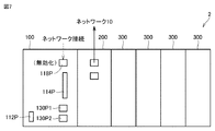
図7は、ネットワークポートへの接続監視を説明する模式図である。図7を参照して、CPUユニット100の表面には、USBポート112Pと、メモリカードスロット114Pと、ネットワークポート118Pと、フィールドネットワークポート130P1,130P2とが配置されている。ネットワークポート118Pは、CPUユニット100をネットワーク接続するためのポートである。
FIG. 7 is a schematic diagram illustrating connection monitoring to a network port. With reference to FIG. 7, a
制御装置2の運用中においては、使用しないネットワークポート118Pは無効化されているとする。このような状態において、ネットワークポート118Pにケーブルが接続されると、セキュリティ事象が発生したと判断してもよい。なお、制御装置2の停止中あるいはメンテナンス中においては、ネットワーク接続されることもあるので、制御装置2が運用中であることを、セキュリティ事象の発生と判断するための条件として付加してもよい。
It is assumed that the
このようなネットワークポートへの接続監視は、典型的には、図4に示す状態取得モジュール260により出力されるCPUユニット状態情報を監視することで実現される。
Such connection monitoring to the network port is typically realized by monitoring the CPU unit status information output by the
このように、本実施の形態に係るセキュリティ事象は、CPUユニット100のネットワークポート118Pが無効化されている場合に、ネットワークポート118Pがネットワーク接続されることを含むようにしてもよい。
As described above, the security event according to the present embodiment may include the
(e3−2:USBポートへの接続監視)
次に、セキュリティ設定20として、CPUユニット100のUSBポートへの接続を監視する例について説明する。
(E3-2: Monitoring the connection to the USB port)
Next, an example of monitoring the connection of the
例えば、CPUユニット100のUSBポートなどを介してサポート装置が接続される。このようなサポート装置の接続は、何らかの意図をもった行為であると想定される。そのため、このような無効化されたネットワークポートに対するネットワーク接続が生じると、セキュリティ事象が発生したと判断してもよい。
For example, the support device is connected via the USB port of the
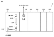
図8は、USBポートへの接続監視を説明する模式図である。図8を参照して、CPUユニット100の表面には、USBポート112Pと、メモリカードスロット114Pと、ネットワークポート118Pと、フィールドネットワークポート130P1,130P2とが配置されている。
FIG. 8 is a schematic diagram illustrating connection monitoring to the USB port. With reference to FIG. 8, a
例えば、制御装置2の運用中において、USBポート112Pを介して何らかのデバイスが接続されると、セキュリティ事象が発生したと判断してもよい。なお、制御装置2の停止中あるいはメンテナンス中においては、サポート装置が接続されることもあるので、制御装置2が運用中であることを、セキュリティ事象の発生と判断するための条件として付加してもよい。
For example, if any device is connected via the
このようなUSBポートへの接続監視は、典型的には、図4に示す状態取得モジュール260により出力されるCPUユニット状態情報を監視することで実現される。
Such connection monitoring to the USB port is typically realized by monitoring the CPU unit status information output by the
このように、本実施の形態に係るセキュリティ事象は、USBポート112Pに任意のデバイスが接続されることを含むようにしてもよい。なお、USBポートに限らず、任意の通信手段を介して、サポート装置などの任意のデバイスが接続されたことをセキュリティ事象とみなすようにしてもよい。そのため、典型的には、セキュリティ事象は、制御装置2で実行されるプログラム(ユーザプログラム30)の開発が可能なサポート装置が制御装置へ接続されることを含むことになる。
As described above, the security event according to the present embodiment may include connecting an arbitrary device to the
(e3−3:電源監視)
次に、セキュリティ設定20として、制御装置2の電源状態を監視する例について説明する。
(E3-3: Power supply monitoring)
Next, an example of monitoring the power supply state of the
例えば、制御装置2の運用中に電源をオン/オフされた場合には、何らかの意図をもった行為であると想定される。そのため、制御装置2の電源がオン/オフされると、セキュリティ事象が発生したと判断してもよい。
For example, when the power is turned on / off during the operation of the
なお、制御装置2において、共通の電源装置からCPUユニット100およびセキュリティユニット200へ電源が供給されている場合も想定される。このような構成においては、電源が遮断されることで、セキュリティユニット200への電源供給も遮断されることが想定される。
In the
このような場合には、セキュリティユニット200の内部にバッテリなどを配置しておき、外部電源が遮断された場合であっても、そのバッテリからの電力によりセキュリティ監視を継続するようにしてもよい。
In such a case, a battery or the like may be arranged inside the
制御装置2の電源状態の監視は、典型的には、図4に示す状態取得モジュール260により出力されるCPUユニット状態情報を監視することで実現される。
Monitoring of the power supply state of the
このように、本実施の形態に係るセキュリティ事象は、制御装置2の電源状態が変化したことを含むようにしてもよい。
As described above, the security event according to the present embodiment may include the change in the power supply state of the
(e3−4:ハードスイッチ監視)
次に、セキュリティ設定20として、制御装置2に設けられたハードスイッチの状態を監視する例について説明する。
(E3-4: Hard switch monitoring)
Next, an example of monitoring the state of the hard switch provided in the
例えば、制御装置2の運用中にCPUユニット100に設けられたディップスイッチ(通常は、CPUユニット100の動作モードなどを設定するために用いられる)が操作された場合には、何らかの意図をもった行為であると想定される。そのため、CPUユニット100のハードスイッチ(例えば、ディップスイッチ)が操作されると、セキュリティ事象が発生したと判断してもよい。
For example, if the DIP switch provided in the CPU unit 100 (usually used to set the operation mode of the
なお、CPUユニット100のハードスイッチとしては、ディップスイッチに限らず、ロータリースイッチやトグルスイッチなどが想定される。
The hard switch of the
このような制御装置2に設けられたハードスイッチの状態監視は、典型的には、図4に示す状態取得モジュール260により出力されるCPUユニット状態情報を監視することで実現される。
The state monitoring of the hard switch provided in such a
このように、本実施の形態に係るセキュリティ事象は、制御装置2に設けられたハードスイッチの状態が変化したことを含むようにしてもよい。
As described above, the security event according to the present embodiment may include the change in the state of the hard switch provided in the
(e3−5:周囲環境監視)
次に、セキュリティ設定20として、制御装置2の周囲環境を監視する例について説明する。
(E3-5: Surrounding environment monitoring)
Next, an example of monitoring the surrounding environment of the
通常、制御装置2は、所定の上限温度以下になるように、制御盤などに収容されているが、不審者が制御盤の冷却ファンを停止するなどの行為を行うと、制御盤内の温度が上昇し得る。このような制御装置の運用中における周囲環境に変化が生じると、セキュリティ事象が発生したと判断してもよい。具体例としては、最大定格温度が55℃であるとすれば、それ以下の例えば50℃に到達すると、セキュリティ事象の発生と判断してもよい。
Normally, the
このような制御装置2の周囲環境の監視は、典型的には、図4に示す状態取得モジュール260により出力されるCPUユニット状態情報を監視することで実現される。
Such monitoring of the surrounding environment of the
このように、本実施の形態に係るセキュリティ事象は、制御装置2の周囲環境が予め定められた条件になったことを含むようにしてもよい。
As described above, the security event according to the present embodiment may include that the surrounding environment of the
(e4−1:ユーザ認証:その1)
次に、セキュリティ設定20として、サポート装置からCPUユニット100へのアクセスにおいて実施されるユーザ認証の認証結果を監視する例について説明する。
(E4-1: User authentication: Part 1)
Next, as the security setting 20, an example of monitoring the authentication result of the user authentication performed in the access from the support device to the
図9は、サポート装置800からCPUユニット100へのアクセス時の処理を説明するための模式図である。図9を参照して、サポート装置800からCPUユニット100へのアクセスする際には、両者を接続した上で、ユーザがサポート装置800を利用して認証情報(典型的には、ユーザ名およびパスワード)を入力する。CPUユニット100は、ユーザからの認証情報に基づいて認証処理を実行する。そして、CPUユニット100は、サポート装置800に対して認証結果を応答する。認証処理が成功した場合には、CPUユニット100は、サポート装置800からのアクセスを許可する。
FIG. 9 is a schematic diagram for explaining a process at the time of access from the
一方、認証処理が失敗した場合には、不正アクセスの可能性もあるので、セキュリティ事象の発生と判断してもよい。すなわち、サポート装置800からCPUユニット100へのアクセス時の認証処理の失敗をトリガとして、セキュリティ事象の発生と判断してもよい。
On the other hand, if the authentication process fails, there is a possibility of unauthorized access, so it may be determined that a security event has occurred. That is, it may be determined that a security event has occurred, triggered by a failure in the authentication process when the
なお、単純な入力ミスの場合も想定されるため、サポート装置800からCPUユニット100へのアクセス時の認証処理の失敗が複数回連続した場合に限って、セキュリティ事象の発生と判断してもよい。
Since a simple input error is also assumed, it may be determined that a security event has occurred only when the authentication process fails a plurality of times when accessing the
このようなサポート装置800からCPUユニット100へのアクセス時におけるユーザ認証の認証結果の監視は、典型的には、図4に示す状態取得モジュール260により出力されるCPUユニット状態情報を監視することで実現される。
Monitoring of the authentication result of user authentication at the time of access from the
このように、本実施の形態に係るセキュリティ事象は、外部から制御装置2またはCPUユニット100へのアクセス時に要求されるユーザ認証が失敗したことを含むようにしてもよい。
As described above, the security event according to the present embodiment may include the failure of user authentication required when accessing the
(e4−2:ユーザ認証:その2)
次に、セキュリティ設定20として、ネットワークからセキュリティユニット200へのアクセスにおいて実施されるユーザ認証の認証結果を監視する例について説明する。
(E4-2: User authentication: Part 2)
Next, an example of monitoring the authentication result of the user authentication performed in the access from the network to the
上述の図4に示すように、セキュリティユニット200は、ユーザ認証モジュール266を有しており、ネットワーク10を介してセキュリティユニット200へアクセスする際には、ユーザ認証が実行される。
As shown in FIG. 4 above, the
このユーザ認証が失敗した場合においても、上述の処理と同様に、認証処理の失敗をトリガとして、セキュリティ事象の発生と判断してもよい。すなわち、本実施の形態に係るセキュリティ事象は、外部から制御装置2またはCPUユニット100へのアクセス時に要求されるユーザ認証が失敗したことを含むようにしてもよい。
Even when this user authentication fails, it may be determined that a security event has occurred with the failure of the authentication process as a trigger, as in the above-mentioned process. That is, the security event according to the present embodiment may include the failure of user authentication required when accessing the
(e4−3:プログラム追加・更新/設定変更)
次に、セキュリティ設定20として、CPUユニット100で実行されるプログラムの追加・更新および/または設定の変更を監視する例について説明する。
(E4-3: Program addition / update / setting change)
Next, an example of monitoring the addition / update and / or setting change of the program executed by the
図10は、サポート装置800からCPUユニット100に格納されているプログラムおよび/または設定を変更する処理を説明するための模式図である。図10を参照して、ユーザは、サポート装置800上で任意のユーザプログラムを作成または改変した上で、当該作成または改変後のユーザプログラムをCPUユニット100へ転送する。それによって、CPUユニット100に新たにユーザプログラムがインストールされ、あるいは、既に格納されていたユーザプログラムが更新される。
FIG. 10 is a schematic diagram for explaining a process of changing a program and / or a setting stored in the
あるいは、ユーザは、サポート装置800を操作することで、CPUユニット100に保持されている設定を変更することもできる。
Alternatively, the user can change the settings held in the
このようなCPUユニット100に対するプログラムの追加、CPUユニット100で実行されるプログラムの更新、CPUユニット100における設定の変更などによって、CPUユニット100の挙動が変化するため、このような操作がなされたことをトリガとして、セキュリティ事象の発生と判断してもよい。
Since the behavior of the
さらに、サポート装置800からは、CPUユニット100の主メモリ106に保持されているワーキングデータをオールクリアすることが可能である。このようなオールクリアすることで、CPUユニット100のプログラムは初期状態が実行開始されることになる。このような初期状態からの実行は、それ以前の挙動とは異なる挙動を示す可能性があるため、セキュリティ事象の発生と判断してもよい。
Further, from the
このようなCPUユニット100におけるプログラムの追加・変更および/または設定の変更のイベントは、典型的には、図4に示す状態取得モジュール260により出力されるCPUユニット状態情報を監視することで検知される。同様に、CPUユニット100の主メモリ106に対するオールクリアのイベントについても、図4に示す状態取得モジュール260により出力されるCPUユニット状態情報を監視することで検知される。
Such an event of program addition / change and / or setting change in the
このように、本実施の形態に係るセキュリティ事象は、制御装置2で実行されるプログラムの追加および変更、ならびに、制御装置2における設定の変更のうち、いずれかが生じたことを含むようにしてもよい。また、本実施の形態に係るセキュリティ事象は、CPUユニット100の主メモリ106に対するオールクリアの操作などがなされたことを含むようにしてもよい。
As described above, the security event according to the present embodiment may include the addition and change of the program executed by the
<F.通知>
次に、セキュリティ事象の発生の検知に応答した通知のいくつかの例について説明する。
<F. Notification>
Next, some examples of notifications in response to the detection of the occurrence of a security event will be described.
(f1:電子メールによる通知)
まず、セキュリティユニット200からの電子メールによりセキュリティ事象の発生を通知する形態について説明する。
(F1: Notification by e-mail)
First, a form for notifying the occurrence of a security event by e-mail from the
図11は、本実施の形態に係るセキュリティユニット200から送信される電子メールの一例を説明するための模式図である。図11を参照して、電子メールの表示画面550は、セキュリティユニット200からの電子メールに含まれる、サブジェクト表示欄552と、送信元表示欄554と、受信日時欄556と、本文欄558とを含む。
FIG. 11 is a schematic diagram for explaining an example of an e-mail transmitted from the
サブジェクト表示欄552には、セキュリティ事象の発生を通知するメッセージとともに、当該セキュリティ事象が発生した制御装置2を特定するための情報が表示されている。送信元表示欄554には、電子メールを送信したセキュリティユニット200のサービスを示す情報が表示されている。受信日時欄556には、セキュリティユニット200からの電子メールを受信した日時が表示されている。
In the
本文欄558には、発生したセキュリティ事象の内容を特定するためのコード、発生時刻、発生場所、緊急度等の情報が表示されている。
In the
さらに、本文欄558には、発生したセキュリティ事象の詳細を確認するためのリンク情報560が埋め込まれていてもよく、ユーザがリンク情報560を選択することで、当該電子メールの送信元であるセキュリティユニット200、あるいは、セキュリティユニット200からの情報を収集している任意のサーバ装置へアクセスすることで、発生したセキュリティ事象の詳細情報を取得できるようになっている。
Further, the
図11に示す電子メールの内容は一例であり、任意の内容を電子メールにより通知してもよい。 The content of the e-mail shown in FIG. 11 is an example, and any content may be notified by e-mail.
なお、通知される電子メールは、任意のデバイスにより閲覧可能である。任意のデバイスとしては、パーソナルコンピュータ、スマートフォン、タブレットなどが想定される。 The notified e-mail can be viewed by any device. As an arbitrary device, a personal computer, a smartphone, a tablet, or the like is assumed.
このように、本実施の形態に係るセキュリティユニット200は、何らかのセキュリティ事象の発生を検知すると、その検知したセキュリティ事象を電子メールの手段を用いて、外部へ通知する。
As described above, when the
(f2:表示装置500への通知)
次に、セキュリティユニット200から表示装置500へセキュリティ事象の発生を通知する形態について説明する。
(F2: Notification to display device 500)
Next, a mode for notifying the occurrence of a security event from the
図12は、本実施の形態に係るセキュリティユニット200から表示装置500へのセキュリティ事象の通知の一例を説明するための模式図である。図12を参照して、表示装置500のディスプレイには、操業用の画面表示がなされている。画面表示には、制御対象を示すオブジェクト502に加えて、制御装置2を収容している制御盤を示すオブジェクト504が表示されていてもよい。
FIG. 12 is a schematic diagram for explaining an example of notification of a security event from the
このようなユーザインターフェイス画面が表示されている状態において、何らかのセキュリティ事象の発生が検知されると、当該セキュリティ事象が発生した制御装置2を収容している制御盤に対応する位置に、通知内容を示すオブジェクト506をポップアップ表示してもよい。
When the occurrence of some security event is detected while such a user interface screen is displayed, the notification content is sent to the position corresponding to the control panel accommodating the
オブジェクト506には、セキュリティ事象の発生を示すメッセージとともに、当該セキュリティ事象が発生した日時および緊急度などが表示されてもよい。図12の表示例に限らず、より多くの情報を表示するようにしてもよいし、逆に、より簡素な表示内容としてもよい。
The
さらに、表示装置500からは、セキュリティ事象の発生を知らせるための通知音508を発するようにしてもよい。
Further, the
なお、通知先の表示装置500は、セキュリティユニット200と同一のネットワークに接続されているものに限らず、セキュリティユニット200が通信可能であれば、いずれのネットワークに接続されている表示装置500を通知先としてもよい。
The
このように、本実施の形態に係るセキュリティユニット200は、何らかのセキュリティ事象の発生を検知すると、その検知したセキュリティ事象をネットワーク接続された表示装置へ通知する。
As described above, when the
(f3:データベース/クラウドサービスへの通知)
次に、セキュリティユニット200からデータベースまたはクラウドサービスへセキュリティ事象の発生を通知する形態について説明する。
(F3: Notification to database / cloud service)
Next, a mode for notifying the occurrence of a security event from the
図13は、本実施の形態に係るセキュリティユニット200からデータベースへのセキュリティ事象の通知の一例を説明するための模式図である。図13を参照して、例えば、ネットワーク10に接続されているサーバ装置600にデータベースとしての処理を実装するとともに、セキュリティユニット200が何らかのセキュリティ事象の発生を検知するとその内容をサーバ装置600に通知する。
FIG. 13 is a schematic diagram for explaining an example of notification of a security event from the
サーバ装置600は、セキュリティユニット200からの通知の内容を逐次収集する。そして、サーバ装置600は、外部からの要求(クエリ)に応答して、指定されたセキュリティ事象の内容を応答するようにしてもよい。
The
図13には、ネットワーク10に接続されるサーバ装置600を通知先とする例を示すが、これに限らず、インターネット上の任意のサーバ装置(すなわち、クラウドサービス)へセキュリティ事象の通知を行ってもよい。
FIG. 13 shows an example in which the
クラウドサービスを利用することで、セキュリティ事象を監視するためだけにサーバ装置600を用意するような必要がなくなる。
By using the cloud service, it is not necessary to prepare the
このように、本実施の形態に係るセキュリティユニット200は、何らかのセキュリティ事象の発生を検知すると、その検知したセキュリティ事象をネットワーク接続されたデータベース/クラウドサービスへ通知する。
As described above, when the
(f4:他の制御装置への通知)
次に、セキュリティユニット200から他の制御装置へセキュリティ事象の発生を通知する形態について説明する。
(F4: Notification to other control devices)
Next, a mode for notifying the occurrence of a security event from the
図14は、本実施の形態に係るセキュリティユニット200から他の制御装置へのセキュリティ事象の通知の一例を説明するための模式図である。図14を参照して、例えば、同一のネットワーク10に複数の制御装置2が接続されており、それぞれの制御装置2がセキュリティユニット200を有しているような構成を想定する。
FIG. 14 is a schematic diagram for explaining an example of notification of a security event from the
いずれかのセキュリティユニット200が何らかのセキュリティ事象の発生を検知すると、他の制御装置2のセキュリティユニット200に対して、検知したセキュリティ事象の内容を通知する。他のセキュリティユニット200から通知を受けたセキュリティユニット200は、その通知の内容を逐次収集する。
When any of the
このような構成を採用することで、セキュリティユニット200間でセキュリティ事象の相互検知が可能になる。
By adopting such a configuration, mutual detection of security events becomes possible between the
さらに、セキュリティ事象の通知を受けた他の制御装置2は、その通知の緊急度などに応じて、接続されているフィールドデバイスを用いて、何らかの物理的な報知(音、光、振動など)を行うようにしてもよい。
Further, the
このように、本実施の形態に係るセキュリティユニット200は、何らかのセキュリティ事象の発生を検知すると、その検知したセキュリティ事象をネットワーク接続された他の制御装置2へ通知する。
As described above, when the
(f5:イベント通知)
次に、セキュリティユニット200からセキュリティ事象の発生を、ネットワークを介してイベント通知する形態について説明する。
(F5: Event notification)
Next, a mode for notifying the occurrence of a security event from the
図15は、本実施の形態に係るセキュリティユニット200からネットワークを介してイベント通知する一例を説明するための模式図である。図15を参照して、ネットワーク10にセキュリティ事象の発生を報知するための報知部1000を配置した構成を想定する。
FIG. 15 is a schematic diagram for explaining an example of event notification from the
セキュリティユニット200が何らかのセキュリティ事象の発生を検知すると、ネットワーク10を介して、報知部1000に対して通知パケットを送出する。報知部1000は、セキュリティユニット200からの通知パケットを受信すると、その通知パケットの内容に従って、物理的な報知(音、光、振動など)を開始する。
When the
通知パケットとしては、例えば、SNMP(Simple Network Management Protocol)トラップなどを利用できる。SNMPトラップに限られず、イベントを通知できるものであれば、どのようなプロコトルを採用してもよい。 As the notification packet, for example, an SNMP (Simple Network Management Protocol) trap or the like can be used. Not limited to the SNMP trap, any protocol that can notify the event may be adopted.
このような構成を採用することで、ネットワーク上の任意の位置に配置された報知部に対してセキュリティ事象の発生を通知できる。 By adopting such a configuration, it is possible to notify the occurrence of a security event to the notification unit arranged at an arbitrary position on the network.
このように、本実施の形態に係るセキュリティユニット200は、何らかのセキュリティ事象の発生を検知すると、その検知したセキュリティ事象を、ネットワークを介してイベント通知するようにしてもよい。このようなイベント通知を受けて、ネットワーク上に配置された報知部1000は報知動作を開始するようにしてもよい。
As described above, when the
(f6:緊急度/優先度表示)
上述したように、本実施の形態に係る制御システム1においては、1または複数の状態値やイベントを監視して、セキュリティ事象の発生の有無を判断する。通常、それぞれのセキュリティ事象は、各事象に応じた緊急度および/または優先度を有しており、必ずしも同一ではない。
(F6: Urgency / priority display)
As described above, in the
そこで、監視対象のセキュリティ事象毎に緊急度および/または優先度を予め設定しておき、何らかのセキュリティ事象の発生が検知されると、当該検知されたセキュリティ事象の緊急度および/または優先度を併せて通知するようにしてもよい。 Therefore, the urgency and / or priority is set in advance for each security event to be monitored, and when the occurrence of any security event is detected, the urgency and / or priority of the detected security event is combined. May be notified.
このような緊急度および/または優先度の通知方法としては、上述の図11および図12に示すような文字情報を用いてもよいし、図15に示すような報知部1000を用いる場合には、報知部1000が発する色、点灯パターン、音色、音量などを異ならせることで通知してもよい。
As such an urgency and / or priority notification method, the character information as shown in FIGS. 11 and 12 may be used, or when the
検知されたセキュリティ事象の緊急度および/または優先度を通知することで、その通知を受けたユーザは、どの程度の緊急度および/または優先度で、当該検知されたセキュリティ事象に対する対処を行わなければならないのかを即座に把握できる。 By notifying the urgency and / or priority of the detected security event, the user who receives the notification must take action on the detected security event with the degree of urgency and / or priority. You can instantly know if you have to.
<G.処理手順>
次に、本実施の形態に係るセキュリティユニット200におけるセキュリティ事象を監視する処理手順の一例について説明する。
<G. Processing procedure>
Next, an example of a processing procedure for monitoring a security event in the
図16は、本実施の形態に係るセキュリティユニット200におけるセキュリティ事象を監視する処理手順を示すフローチャートである。図16に示す各ステップは、典型的には、セキュリティユニット200のプロセッサ202がファームウェア22を実行することで実現される。図16に示す処理手順は、所定周期毎に繰返し実行され、あるいは、予め定められたイベント発生毎に実行される。
FIG. 16 is a flowchart showing a processing procedure for monitoring a security event in the
図16を参照して、セキュリティユニット200は、ネットワーク10を介したデータの送受信が発生したか否かを判断する(ステップS100)。ネットワーク10を介したデータの送受信が発生していなければ(ステップS100においてNO)、ステップS102〜S106の処理はスキップされる。
With reference to FIG. 16, the
ネットワーク10を介したデータの送受信が発生すれば(ステップS100においてYES)、セキュリティユニット200は、データの送信先および/または送信元がアクセスコントロールによって制限されているか否かを判断する(ステップS102)。データの送信先および/または送信元がアクセスコントロールによって制限されていれば(ステップS102においてYES)、セキュリティユニット200は、セキュリティ事象の発生と判断する(ステップS104)。そして、ステップS120に規定される通知処理が実行される。
If data transmission / reception occurs via the network 10 (YES in step S100), the
データの送信先および/または送信元がアクセスコントロールによって制限されていなければ(ステップS102においてNO)、セキュリティユニット200は、データの送信または受信のパターンが予め定められたセキュリティ事象の発生と判断されるパターンと合致するか否かを判断する(ステップS106)。データの送信または受信のパターンが予め定められたセキュリティ事象の発生と判断されるパターンと合致すれば(ステップS106においてYES)、セキュリティユニット200は、セキュリティ事象の発生と判断する(ステップS104)。そして、ステップS120に規定される通知処理が実行される。
If the destination and / or source of the data is not restricted by access control (NO in step S102), the
続いて、セキュリティユニット200は、CPUユニット100からCPUユニット状態情報を取得し(ステップS108)、取得したCPUユニット状態情報がセキュリティ設定20に規定されたいずれかのセキュリティ事象の条件に合致しているか否かを判断する(ステップS110)。取得したCPUユニット状態情報がいずれかのセキュリティ事象の条件に合致していれば(ステップS110においてYES)、セキュリティユニット200は、セキュリティ事象の発生と判断する(ステップS104)。そして、ステップS120に規定される通知処理が実行される。
Subsequently, the
取得したCPUユニット状態情報がいずれかのセキュリティ事象の条件に合致していなければ(ステップS110においてNO)、処理は終了する。 If the acquired CPU unit status information does not meet the condition of any security event (NO in step S110), the process ends.
ステップS120において、セキュリティユニット200は、検知されたセキュリティ事象に応じて、通知処理を実行する。そして、処理は終了する。
In step S120, the
<H.変形例>
(h1:一体型)
上述の本実施の形態に係る制御システム1においては、CPUユニット100にセキュリティユニット200を接続する構成を例示したが、このような分離型ではなく、両者を一体化した構成を採用してもよい。この場合には、CPUユニット100の内部に、セキュリティユニット200が提供する処理を実現するためのソフトウェア実装および/またはハードウェア実装の構成が配置される。
<H. Modification example>
(H1: Integrated type)
In the
このような一体型の構成を採用することで、制御システム全体を省スペース化できる。
(h2:外付型)
上述の本実施の形態に係る制御システム1においては、CPUユニット100のネットワークポートではなく、セキュリティユニット200のネットワークポートを利用して、ネットワーク接続する構成を例示したが、本実施の形態に係るセキュリティ事象の監視処理を既存の制御装置に適用する場合には、外付型のセキュリティユニットを採用するようにしてもよい。
By adopting such an integrated configuration, the entire control system can be saved in space.
(H2: External type)
In the
図17は、本実施の形態の変形例に係る制御システム1Aの概略構成を示す模式図である。図17を参照して、制御システム1Aにおいては、制御装置2Aは、CPUユニット100と1または複数の機能ユニット300とにより構成される。セキュリティユニット200Aは、ネットワーク10と制御装置2Aとの間を仲介するように配置される。
FIG. 17 is a schematic diagram showing a schematic configuration of the
より具体的には、セキュリティユニット200Aは、2つのネットワークポートを有しており、一方のネットワークポートはネットワーク10に接続されるとともに、他方のネットワークポートは制御装置2Aに含まれるCPUユニット100のネットワークポート118Pに接続されている。このような構成において、CPUユニット100は、セキュリティユニット200Aを介して、ネットワーク10に接続されたデバイスとの間でデータ通信を行う。
More specifically, the
セキュリティユニット200Aは、CPUユニット100から送出されるデータおよびCPUユニット100で受信されるデータを監視することで、セキュリティ事象の発生の有無を常時監視できる。
The
セキュリティユニット200Aは、さらに、CPUユニット100と別のデータ伝送手段を介して接続されていてもよい。このような別のデータ伝送手段を採用することで、セキュリティユニット200Aは、CPUユニット100のCPUユニット状態情報を取得することができる。このようなCPUユニット状態情報によって、CPUユニット100に対する直接のアクセスによって生じるセキュリティ事象の発生についても常時監視できる。
The
(h3:その他)
本実施の形態に係るセキュリティユニットは、CPUユニット100およびCPUユニット100を含む制御装置2におけるセキュリティ事象の発生を監視できるものであれば、どのような形態で実装されてもよい。
(H3: Other)
The security unit according to the present embodiment may be implemented in any form as long as it can monitor the occurrence of security events in the
<I.付記>
上述したような本実施の形態は、以下のような技術思想を含む。
[構成1]
制御対象を制御する制御装置(2)であって、
前記制御対象に応じて作成されたプログラムを実行するプログラム実行部(102)と、
前記制御装置に対する外部からのアクセスにおいてセキュリティ事象が発生したか否かを判断する検知部(262)と、
前記セキュリティ事象が発生したと検知されると、当該発生したセキュリティ事象に応じた通知先へ通知する通知部(264)とを備え、
前記セキュリティ事象は、予め定められた規則に適合しない事象を含む、制御装置。
[構成2]
前記セキュリティ事象は、
前記制御装置の動作を停止または性能を低下させる挙動および行為、
前記制御装置におけるプログラムの実行処理を停止または性能を低下させる挙動および行為、ならびに
前記制御対象の動作を停止または性能を低下させる挙動および行為、のいずれかを含む、構成1に記載の制御装置。
[構成3]
前記セキュリティ事象は、データの送信先または送信元のネットワークアドレス、物理アドレス、ポート番号のうちいずれかが、予め定められたアクセスを許可されたリストに含まれていない、および、予め定められたアクセスを禁止されたリストに含まれている、のいずれかに該当することを含む、構成1または2に記載の制御装置。
[構成4]
前記制御装置は、前記プログラム実行部を含む第1のユニット(100)と、前記検知部を含む第2のユニット(200)を備え、
前記第1のユニットは、ネットワーク接続するためのポート(118P)を有しており、
前記セキュリティ事象は、前記第1のユニットのポートが無効化されている場合に、当該ポートがネットワーク接続されることを含む、構成1〜3のいずれか1項に記載の制御装置。
[構成5]
前記セキュリティ事象は、外部から前記制御装置へのアクセス時に要求されるユーザ認証が失敗したことを含む、構成1〜4のいずれか1項に記載の制御装置。
[構成6]
前記セキュリティ事象は、前記制御装置で実行されるプログラムの開発が可能なサポート装置が前記制御装置へ接続されることを含む、構成1〜5のいずれか1項に記載の制御装置。
[構成7]
前記セキュリティ事象は、前記制御装置で実行されるプログラムの追加および変更、ならびに、前記制御装置における設定の変更のうち、いずれかが生じたことを含む、構成1〜6のいずれか1項に記載の制御装置。
[構成8]
前記通知部は、セキュリティ事象の発生をネットワークを介してイベント通知する、構成1〜7のいずれか1項に記載の制御装置。
[構成9]
ネットワーク上に配置された報知部(1000)は、前記通知部からのイベント通知を受けて、報知動作を開始する、構成8に記載の制御装置。
[構成10]
制御対象を制御する制御システム(1)であって、
前記制御対象に応じて作成されたプログラムを実行するプログラム実行部を含む第1のユニット(100)と、
前記第1のユニットに対する外部からのアクセスにおいてセキュリティ事象が発生したか否かを判断する検知部(262)、ならびに、前記セキュリティ事象が発生したと検知されると、当該発生したセキュリティ事象に応じた通知先へ通知する通知部(264)を含む第2のユニット(200)とを備え、
前記セキュリティ事象は、予め定められた規則に適合しない事象を含む、制御システム。
<I. Addendum>
The present embodiment as described above includes the following technical ideas.
[Structure 1]
A control device (2) that controls a controlled object.
A program execution unit (102) that executes a program created according to the control target, and
A detection unit (262) that determines whether or not a security event has occurred in an external access to the control device, and
When it is detected that the security event has occurred, it is provided with a notification unit (264) that notifies the notification destination according to the security event that has occurred.
The security event is a control device including an event that does not conform to a predetermined rule.
[Structure 2]
The security event is
Behaviors and actions that stop the operation of the control device or reduce its performance,
The control device according to
[Structure 3]
The security event is that one of the network address, physical address, or port number of the destination or source of the data is not included in the predetermined list of permitted access, and the predetermined access. The control device according to
[Structure 4]
The control device includes a first unit (100) including the program execution unit and a second unit (200) including the detection unit.
The first unit has a port (118P) for connecting to a network.
The control device according to any one of
[Structure 5]
The control device according to any one of
[Structure 6]
The control device according to any one of
[Structure 7]
The security event is described in any one of
[Structure 8]
The control device according to any one of
[Structure 9]
The control device according to configuration 8, wherein the notification unit (1000) arranged on the network receives an event notification from the notification unit and starts a notification operation.
[Structure 10]
A control system (1) that controls a controlled object.
A first unit (100) including a program execution unit that executes a program created according to the control target, and
The detection unit (262) that determines whether or not a security event has occurred in the external access to the first unit, and when it is detected that the security event has occurred, responds to the security event that has occurred. It is equipped with a second unit (200) including a notification unit (264) that notifies the notification destination.
The security event is a control system that includes an event that does not comply with predetermined rules.
<J.まとめ>
本実施の形態に係る制御装置および制御システムによれば、制御装置および制御システムのネットワーク化あるいはインテリジェント化に伴って生じ得る脅威に対する保護という新たな課題を解決できる。
<J. Summary>
According to the control device and the control system according to the present embodiment, it is possible to solve a new problem of protection against threats that may occur due to networking or intelligentization of the control device and the control system.
今回開示された実施の形態はすべての点で例示であって制限的なものではないと考えられるべきである。本発明の範囲は、上記した説明ではなく、特許請求の範囲によって示され、特許請求の範囲と均等の意味および範囲内でのすべての変更が含まれることが意図される。 It should be considered that the embodiments disclosed this time are exemplary in all respects and not restrictive. The scope of the present invention is shown by the scope of claims, not the above description, and is intended to include all modifications within the meaning and scope equivalent to the scope of claims.
1,1A 制御システム、2,2A 制御装置、4 リモートIO装置、6 フィールドネットワーク、10 ネットワーク、20 セキュリティ設定、22 ファームウェア、24 履歴情報、30 ユーザプログラム、32 システムプログラム、100 CPUユニット、102,202 プロセッサ、104,204 チップセット、106,206 主メモリ、108,208 ストレージ、110,210 ユニット間インターフェイス、112 USBインターフェイス、112P USBポート、114 メモリカードインターフェイス、114P メモリカードスロット、116 メモリカード、118,220 ネットワークインターフェイス、118P ネットワークポート、120 内部バスコントローラ、130 フィールドネットワークコントローラ、130P1,130P2 フィールドネットワークポート、200,200A セキュリティユニット、222 送受信部、224 コントローラ、226 バッファ、250 フレーム抽出モジュール、252 解析モジュール、254 内容解析処理、256 特徴抽出処理、258 統計処理、260 状態取得モジュール、262 検知モジュール、264 通知モジュール、266 ユーザ認証モジュール、300 機能ユニット、400 カプラユニット、500 表示装置、502,504,506 オブジェクト、508 通知音、550 表示画面、552 サブジェクト表示欄、554 元表示欄、556 受信日時欄、558 本文欄、560 リンク情報、600 サーバ装置、700 ゲートウェイ、800 サポート装置、900 デバイス、1000 報知部。 1,1A control system, 2,2A control device, 4 remote IO device, 6 field network, 10 network, 20 security settings, 22 firmware, 24 history information, 30 user program, 32 system program, 100 CPU unit, 102, 202 Processor, 104,204 chipset, 106,206 main memory, 108,208 storage, 110,210 unit-to-unit interface, 112 USB interface, 112P USB port, 114 memory card interface, 114P memory card slot, 116 memory card, 118, 220 network interface, 118P network port, 120 internal bus controller, 130 field network controller, 130P1, 130P2 field network port, 200, 200A security unit, 222 transmitter / receiver, 224 controller, 226 buffer, 250 frame extraction module, 252 analysis module, 254 Content analysis processing, 256 feature extraction processing, 258 statistical processing, 260 status acquisition module, 262 detection module, 264 notification module, 266 user authentication module, 300 function unit, 400 coupler unit, 500 display device, 502,504,506 objects. , 508 Notification sound, 550 display screen, 552 subject display column, 554 original display column, 556 received date and time column, 558 body column, 560 link information, 600 server device, 700 gateway, 800 support device, 900 device, 1000 notification unit.
Claims (10)
前記制御対象に応じて作成されたプログラムを実行するプログラム実行部と、
前記制御装置に対する外部からのアクセスにおいてセキュリティ事象が発生したか否かを判断する検知部と、
前記セキュリティ事象が発生したと検知されると、当該発生したセキュリティ事象に応じた通知先へ通知する通知部と、
ネットワーク接続するためのポートとを備え、
前記セキュリティ事象は、前記ポートが無効化されている場合に、当該ポートがネットワーク接続されることを含む、制御装置。 A control device that controls a controlled object,
A program execution unit that executes a program created according to the control target, and
A detector that determines whether or not a security event has occurred in an external access to the control device,
When it is detected that the security event has occurred, a notification unit that notifies the notification destination according to the security event that has occurred, and a notification unit .
Equipped with a port for network connection
The security event is a control device comprising connecting the port to a network when the port is disabled.
前記制御対象に応じて作成されたプログラムを実行するプログラム実行部と、
前記制御装置に対する外部からのアクセスにおいてセキュリティ事象が発生したか否かを判断する検知部と、
前記セキュリティ事象が発生したと検知されると、当該発生したセキュリティ事象に応じた通知先へ通知する通知部とを備え、
前記セキュリティ事象は、前記セキュリティ事象は、前記制御装置で実行されるプログラムの開発が可能なサポート装置が前記制御装置へ接続されることを含む、制御装置。 A control device that controls a controlled object,
A program execution unit that executes a program created according to the control target, and
A detector that determines whether or not a security event has occurred in an external access to the control device,
When it is detected that the security event has occurred, it is provided with a notification unit that notifies the notification destination according to the security event that has occurred.
The security event is a control device comprising connecting a support device capable of developing a program executed by the control device to the control device.
前記制御装置の動作を停止または性能を低下させる挙動および行為、
前記制御装置におけるプログラムの実行処理を停止または性能を低下させる挙動および行為、ならびに
前記制御対象の動作を停止または性能を低下させる挙動および行為、のいずれかを含む、請求項1または2に記載の制御装置。 The security event is
Behaviors and actions that stop the operation of the control device or reduce its performance,
The invention according to claim 1 or 2 , wherein the behavior and the action of stopping or degrading the performance of the program execution process in the control device and the behavior and the act of stopping or degrading the performance of the controlled object are included. Control device.
前記制御対象に応じて作成されたプログラムを実行するプログラム実行部を含む第1のユニットと、
前記第1のユニットに対する外部からのアクセスにおいてセキュリティ事象が発生したか否かを判断する検知部、ならびに、前記セキュリティ事象が発生したと検知されると、当該発生したセキュリティ事象に応じた通知先へ通知する通知部を含む第2のユニットとを備え、
前記第1のユニットは、ネットワーク接続するためのポートを有しており、
前記セキュリティ事象は、前記第1のユニットのポートが無効化されている場合に、当該ポートがネットワーク接続されることを含む、制御システム。 A control system that controls a controlled object,
A first unit including a program execution unit that executes a program created according to the control target, and
To the detection unit that determines whether or not a security event has occurred in the external access to the first unit, and to the notification destination corresponding to the security event that has occurred when the security event is detected. Equipped with a second unit including a notification unit to notify
The first unit has a port for connecting to a network.
The security event comprises a control system in which a port of the first unit is networked if it is disabled.
前記制御対象に応じて作成されたプログラムを実行するプログラム実行部を含む第1のユニットと、
前記第1のユニットに対する外部からのアクセスにおいてセキュリティ事象が発生したか否かを判断する検知部、ならびに、前記セキュリティ事象が発生したと検知されると、当該発生したセキュリティ事象に応じた通知先へ通知する通知部を含む第2のユニットとを備え、
前記セキュリティ事象は、前記制御システムで実行されるプログラムの開発が可能なサポート装置が前記制御システムへ接続されることを含む、制御システム。 A control system that controls a controlled object,
A first unit including a program execution unit that executes a program created according to the control target, and
To the detection unit that determines whether or not a security event has occurred in the external access to the first unit, and to the notification destination corresponding to the security event that has occurred when the security event is detected. Equipped with a second unit including a notification unit to notify
The security event comprises connecting a support device capable of developing a program executed in the control system to the control system.
Priority Applications (5)
| Application Number | Priority Date | Filing Date | Title |
|---|---|---|---|
| JP2017226145A JP6977507B2 (en) | 2017-11-24 | 2017-11-24 | Controls and control systems |
| CN201880055243.1A CN111052005B (en) | 2017-11-24 | 2018-11-01 | Control device and control system |
| EP18881062.6A EP3715971A4 (en) | 2017-11-24 | 2018-11-01 | Control device and control system |
| PCT/JP2018/040653 WO2019102811A1 (en) | 2017-11-24 | 2018-11-01 | Control device and control system |
| US16/642,357 US11516229B2 (en) | 2017-11-24 | 2018-11-01 | Control device and control system |
Applications Claiming Priority (1)
| Application Number | Priority Date | Filing Date | Title |
|---|---|---|---|
| JP2017226145A JP6977507B2 (en) | 2017-11-24 | 2017-11-24 | Controls and control systems |
Publications (2)
| Publication Number | Publication Date |
|---|---|
| JP2019096149A JP2019096149A (en) | 2019-06-20 |
| JP6977507B2 true JP6977507B2 (en) | 2021-12-08 |
Family
ID=66630611
Family Applications (1)
| Application Number | Title | Priority Date | Filing Date |
|---|---|---|---|
| JP2017226145A Active JP6977507B2 (en) | 2017-11-24 | 2017-11-24 | Controls and control systems |
Country Status (5)
| Country | Link |
|---|---|
| US (1) | US11516229B2 (en) |
| EP (1) | EP3715971A4 (en) |
| JP (1) | JP6977507B2 (en) |
| CN (1) | CN111052005B (en) |
| WO (1) | WO2019102811A1 (en) |
Families Citing this family (4)
| Publication number | Priority date | Publication date | Assignee | Title |
|---|---|---|---|---|
| JP7045958B2 (en) * | 2018-08-20 | 2022-04-01 | 三菱電機株式会社 | Information security system |
| JP7255369B2 (en) * | 2019-06-06 | 2023-04-11 | オムロン株式会社 | control system |
| JP2022138824A (en) | 2021-03-11 | 2022-09-26 | オムロン株式会社 | Control system and control method therefor |
| US11856030B2 (en) | 2021-10-04 | 2023-12-26 | Motorola Solutions, Inc. | Security ecosystem |
Family Cites Families (46)
| Publication number | Priority date | Publication date | Assignee | Title |
|---|---|---|---|---|
| WO1996027155A2 (en) | 1995-02-13 | 1996-09-06 | Electronic Publishing Resources, Inc. | Systems and methods for secure transaction management and electronic rights protection |
| KR100272567B1 (en) * | 1997-12-31 | 2000-11-15 | 서평원 | Mobile Internet in Mobile Communication Network |
| JP3690144B2 (en) | 1998-11-02 | 2005-08-31 | オムロン株式会社 | Programmable controller |
| US6344802B1 (en) * | 1999-03-29 | 2002-02-05 | Kabushiki Kaisha Toshiba | Control system |
| JP2003108222A (en) | 2001-10-02 | 2003-04-11 | Kurita Water Ind Ltd | Facility management system |
| US7854009B2 (en) * | 2003-06-12 | 2010-12-14 | International Business Machines Corporation | Method of securing access to IP LANs |
| JP2005080024A (en) | 2003-09-01 | 2005-03-24 | Ricoh Co Ltd | Radio network system and operating method |
| US20050182967A1 (en) * | 2004-02-13 | 2005-08-18 | Microsoft Corporation | Network security device and method for protecting a computing device in a networked environment |
| US7574610B2 (en) * | 2004-09-30 | 2009-08-11 | Microsoft Corporation | Security state watcher |
| JP2006163509A (en) | 2004-12-02 | 2006-06-22 | Olympus Corp | Failure report system |
| US7770205B2 (en) * | 2005-01-19 | 2010-08-03 | Microsoft Corporation | Binding a device to a computer |
| JP4575219B2 (en) * | 2005-04-12 | 2010-11-04 | 株式会社東芝 | Security gateway system and method and program thereof |
| US20060250966A1 (en) * | 2005-05-03 | 2006-11-09 | Yuan-Chi Su | Method for local area network security |
| CN100450012C (en) | 2005-07-15 | 2009-01-07 | 复旦大学 | Invasion detecting system and method based on mobile agency |
| JP4965239B2 (en) * | 2006-12-25 | 2012-07-04 | パナソニック株式会社 | Remote monitoring system |
| JP4506814B2 (en) | 2007-10-31 | 2010-07-21 | 日本電気株式会社 | Data management system |
| CN101232509A (en) * | 2008-02-26 | 2008-07-30 | 杭州华三通信技术有限公司 | Equipment, system and method for supporting insulation mode network access control |
| US8752175B2 (en) * | 2008-10-31 | 2014-06-10 | Hewlett-Packard Development Company, L.P. | Method and apparatus for network intrusion detection |
| US20100235914A1 (en) * | 2009-03-13 | 2010-09-16 | Alcatel Lucent | Intrusion detection for virtual layer-2 services |
| CN101887257B (en) | 2010-06-10 | 2012-05-23 | 浙江工业大学 | Safe and intelligent omnibearing monitoring device for dam |
| EP2600566B1 (en) * | 2010-07-30 | 2017-08-02 | Cyber Solutions Inc. | Unauthorized access blocking control method |
| JP2013030826A (en) | 2011-07-26 | 2013-02-07 | Ricoh Co Ltd | Network monitoring system and network monitoring method |
| JP5687171B2 (en) * | 2011-10-14 | 2015-03-18 | 株式会社日立産機システム | Controller, monitoring unit, and sequence program update method |
| US20140258526A1 (en) | 2011-10-24 | 2014-09-11 | Schneider Electric Industries Sas | Systems and methods of remote communication |
| JP2012123840A (en) | 2012-03-14 | 2012-06-28 | Mitsubishi Electric Corp | Abnormality notification device and abnormality notification system |
| JP6015178B2 (en) | 2012-07-11 | 2016-10-26 | オムロン株式会社 | Safety system |
| US9276877B1 (en) * | 2012-09-20 | 2016-03-01 | Wiretap Ventures, LLC | Data model for software defined networks |
| US9246977B2 (en) * | 2012-12-21 | 2016-01-26 | Tanium Inc. | System, security and network management using self-organizing communication orbits in distributed networks |
| US20150295944A1 (en) | 2013-07-01 | 2015-10-15 | Hitachi, Ltd. | Control system, control method, and controller |
| US8667589B1 (en) | 2013-10-27 | 2014-03-04 | Konstantin Saprygin | Protection against unauthorized access to automated system for control of technological processes |
| US9998426B2 (en) * | 2014-01-30 | 2018-06-12 | Sierra Nevada Corporation | Bi-directional data security for control systems |
| JP6442843B2 (en) | 2014-03-14 | 2018-12-26 | オムロン株式会社 | Control device |
| US9734358B2 (en) * | 2015-01-02 | 2017-08-15 | High Sec Labs Ltd | Self-locking USB protection pug device having LED to securely protect USB jack |
| US9367355B1 (en) * | 2015-01-28 | 2016-06-14 | Yahoo!, Inc. | Resource utilization by one or more tasks |
| US9697355B1 (en) * | 2015-06-17 | 2017-07-04 | Mission Secure, Inc. | Cyber security for physical systems |
| DK3151152T3 (en) * | 2015-09-30 | 2020-06-15 | Secure Nok Tech As | Non-intrusive software agent for monitoring and detection of cyber security events and cyber-attacks in an industrial control system |
| US10038705B2 (en) * | 2015-10-12 | 2018-07-31 | Dell Products, L.P. | System and method for performing intrusion detection in an information handling system |
| IL242808A0 (en) * | 2015-11-26 | 2016-04-21 | Rafael Advanced Defense Sys | System and method for detecting a cyber-attack at scada/ics managed plants |
| JP6633373B2 (en) * | 2015-12-03 | 2020-01-22 | 株式会社東芝 | Control device |
| IL243024A0 (en) * | 2015-12-10 | 2016-02-29 | Shabtai Asaf | Method and system for detecting a plc in a scada system that is sending false telemetry data |
| US9810736B2 (en) * | 2015-12-17 | 2017-11-07 | Raytheon Company | System and apparatus for trusted and secure test ports of integrated circuit devices |
| IL243343A0 (en) * | 2015-12-24 | 2016-04-21 | Bg Negev Technologies & Applic Ltd | A system and method for detecting malicious re-programming of a plc in scada systems using time deception |
| US10848465B2 (en) * | 2016-02-26 | 2020-11-24 | Extreme Networks, Inc. | Dynamic firewalls and forensic gateways |
| CN106411578B (en) * | 2016-09-12 | 2019-07-12 | 国网山东省电力公司电力科学研究院 | A kind of web publishing system and method being adapted to power industry |
| CN106572103B (en) * | 2016-10-28 | 2019-12-13 | 桂林电子科技大学 | hidden port detection method based on SDN network architecture |
| US11575571B2 (en) * | 2020-05-08 | 2023-02-07 | Rockwell Automation Technologies, Inc. | Centralized security event generation policy |
-
2017
- 2017-11-24 JP JP2017226145A patent/JP6977507B2/en active Active
-
2018
- 2018-11-01 EP EP18881062.6A patent/EP3715971A4/en active Pending
- 2018-11-01 US US16/642,357 patent/US11516229B2/en active Active
- 2018-11-01 WO PCT/JP2018/040653 patent/WO2019102811A1/en unknown
- 2018-11-01 CN CN201880055243.1A patent/CN111052005B/en active Active
Also Published As
| Publication number | Publication date |
|---|---|
| US11516229B2 (en) | 2022-11-29 |
| CN111052005B (en) | 2023-07-04 |
| EP3715971A4 (en) | 2021-07-28 |
| EP3715971A1 (en) | 2020-09-30 |
| US20210075801A1 (en) | 2021-03-11 |
| JP2019096149A (en) | 2019-06-20 |
| WO2019102811A1 (en) | 2019-05-31 |
| CN111052005A (en) | 2020-04-21 |
Similar Documents
| Publication | Publication Date | Title |
|---|---|---|
| JP6977507B2 (en) | Controls and control systems | |
| JP7006178B2 (en) | Security monitoring device | |
| CN107005566B (en) | System and method for automatic device detection, device management and remote assistance | |
| JP4373779B2 (en) | Stateful distributed event processing and adaptive maintenance | |
| US9596213B2 (en) | Monitoring arrangement | |
| CN105743878B (en) | Dynamic service handling using honeypots | |
| KR100947211B1 (en) | System for active security surveillance | |
| US11632399B2 (en) | Secure administration of a local communication network comprising at least one communicating object | |
| JP4437107B2 (en) | Computer system | |
| KR20180000100A (en) | Sdn-based network-attacks blocking system for micro server management system protection | |
| JP2005193590A (en) | Printing device | |
| KR101881061B1 (en) | 2-way communication apparatus capable of changing communication mode and method thereof | |
| JP2014063349A (en) | Malware detection device and method | |
| KR101070522B1 (en) | System and method for monitoring and blocking of spoofing attack | |
| JP6690377B2 (en) | Controllers and control systems | |
| JP2006018766A (en) | Network connection management system | |
| JP2017163505A (en) | Monitoring device, switch, communication device, communication system, monitoring method, and monitoring program | |
| JP2009100363A (en) | Network monitoring system, and terminal device | |
| JP3996105B2 (en) | Unauthorized operation monitoring method for customer premises equipment | |
| JP2006252109A (en) | Network access controller, device for remote operation and system | |
| JP4437259B2 (en) | Network management method and network management system | |
| JP2022160511A (en) | End terminal, relay device, PLC device, and communication system | |
| JP2015207970A (en) | Communication inspection module, communication module, and control device | |
| JP2008084279A (en) | Computer monitoring method and computer program |
Legal Events
| Date | Code | Title | Description |
|---|---|---|---|
| A621 | Written request for application examination |
Free format text: JAPANESE INTERMEDIATE CODE: A621 Effective date: 20200304 |
|
| A131 | Notification of reasons for refusal |
Free format text: JAPANESE INTERMEDIATE CODE: A131 Effective date: 20210406 |
|
| A521 | Request for written amendment filed |
Free format text: JAPANESE INTERMEDIATE CODE: A523 Effective date: 20210519 |
|
| TRDD | Decision of grant or rejection written | ||
| A01 | Written decision to grant a patent or to grant a registration (utility model) |
Free format text: JAPANESE INTERMEDIATE CODE: A01 Effective date: 20211012 |
|
| A61 | First payment of annual fees (during grant procedure) |
Free format text: JAPANESE INTERMEDIATE CODE: A61 Effective date: 20211025 |
|
| R150 | Certificate of patent or registration of utility model |
Ref document number: 6977507 Country of ref document: JP Free format text: JAPANESE INTERMEDIATE CODE: R150 |