JP6976974B2 - Coding and decoding of interchannel phase differences between audio signals - Google Patents
Coding and decoding of interchannel phase differences between audio signals Download PDFInfo
- Publication number
- JP6976974B2 JP6976974B2 JP2018566453A JP2018566453A JP6976974B2 JP 6976974 B2 JP6976974 B2 JP 6976974B2 JP 2018566453 A JP2018566453 A JP 2018566453A JP 2018566453 A JP2018566453 A JP 2018566453A JP 6976974 B2 JP6976974 B2 JP 6976974B2
- Authority
- JP
- Japan
- Prior art keywords
- ipd
- value
- signal
- audio signal
- mode
- Prior art date
- Legal status (The legal status is an assumption and is not a legal conclusion. Google has not performed a legal analysis and makes no representation as to the accuracy of the status listed.)
- Active
Links
- 230000005236 sound signal Effects 0.000 title claims description 385
- 230000002123 temporal effect Effects 0.000 claims description 223
- 238000000034 method Methods 0.000 claims description 104
- 238000003860 storage Methods 0.000 claims description 41
- 238000012545 processing Methods 0.000 claims description 29
- 230000003111 delayed effect Effects 0.000 claims description 20
- 230000008569 process Effects 0.000 claims description 8
- 238000013139 quantization Methods 0.000 claims description 7
- 238000009826 distribution Methods 0.000 claims description 2
- 230000000875 corresponding effect Effects 0.000 description 88
- 230000004044 response Effects 0.000 description 63
- 238000006243 chemical reaction Methods 0.000 description 19
- 238000013507 mapping Methods 0.000 description 16
- 230000001364 causal effect Effects 0.000 description 15
- 230000000694 effects Effects 0.000 description 12
- 230000003595 spectral effect Effects 0.000 description 12
- 238000010586 diagram Methods 0.000 description 10
- 230000009466 transformation Effects 0.000 description 9
- 238000004891 communication Methods 0.000 description 8
- 230000010363 phase shift Effects 0.000 description 8
- 230000001052 transient effect Effects 0.000 description 7
- 230000005540 biological transmission Effects 0.000 description 5
- 230000006870 function Effects 0.000 description 5
- 239000006185 dispersion Substances 0.000 description 4
- 230000009471 action Effects 0.000 description 3
- 230000002441 reversible effect Effects 0.000 description 3
- 230000006399 behavior Effects 0.000 description 2
- 230000008901 benefit Effects 0.000 description 2
- 230000001413 cellular effect Effects 0.000 description 2
- 239000002131 composite material Substances 0.000 description 2
- 230000002596 correlated effect Effects 0.000 description 2
- 238000005516 engineering process Methods 0.000 description 2
- 238000010295 mobile communication Methods 0.000 description 2
- 230000009467 reduction Effects 0.000 description 2
- 238000005070 sampling Methods 0.000 description 2
- 238000001228 spectrum Methods 0.000 description 2
- 238000012935 Averaging Methods 0.000 description 1
- 230000006978 adaptation Effects 0.000 description 1
- 230000003044 adaptive effect Effects 0.000 description 1
- 238000003491 array Methods 0.000 description 1
- 230000009286 beneficial effect Effects 0.000 description 1
- 230000003139 buffering effect Effects 0.000 description 1
- 230000008859 change Effects 0.000 description 1
- 238000012937 correction Methods 0.000 description 1
- 230000001934 delay Effects 0.000 description 1
- 230000001419 dependent effect Effects 0.000 description 1
- 238000013461 design Methods 0.000 description 1
- 230000007613 environmental effect Effects 0.000 description 1
- 230000005284 excitation Effects 0.000 description 1
- 238000001914 filtration Methods 0.000 description 1
- 238000009432 framing Methods 0.000 description 1
- 230000007274 generation of a signal involved in cell-cell signaling Effects 0.000 description 1
- 230000006872 improvement Effects 0.000 description 1
- 238000002347 injection Methods 0.000 description 1
- 239000007924 injection Substances 0.000 description 1
- 230000007774 longterm Effects 0.000 description 1
- 238000004519 manufacturing process Methods 0.000 description 1
- 238000012986 modification Methods 0.000 description 1
- 230000004048 modification Effects 0.000 description 1
- 238000004321 preservation Methods 0.000 description 1
- 238000004540 process dynamic Methods 0.000 description 1
- 238000012552 review Methods 0.000 description 1
- 230000001360 synchronised effect Effects 0.000 description 1
- 238000012546 transfer Methods 0.000 description 1
- 238000000844 transformation Methods 0.000 description 1
Images


Classifications
-
- G—PHYSICS
- G10—MUSICAL INSTRUMENTS; ACOUSTICS
- G10L—SPEECH ANALYSIS TECHNIQUES OR SPEECH SYNTHESIS; SPEECH RECOGNITION; SPEECH OR VOICE PROCESSING TECHNIQUES; SPEECH OR AUDIO CODING OR DECODING
- G10L19/00—Speech or audio signals analysis-synthesis techniques for redundancy reduction, e.g. in vocoders; Coding or decoding of speech or audio signals, using source filter models or psychoacoustic analysis
- G10L19/008—Multichannel audio signal coding or decoding using interchannel correlation to reduce redundancy, e.g. joint-stereo, intensity-coding or matrixing
-
- G—PHYSICS
- G10—MUSICAL INSTRUMENTS; ACOUSTICS
- G10L—SPEECH ANALYSIS TECHNIQUES OR SPEECH SYNTHESIS; SPEECH RECOGNITION; SPEECH OR VOICE PROCESSING TECHNIQUES; SPEECH OR AUDIO CODING OR DECODING
- G10L19/00—Speech or audio signals analysis-synthesis techniques for redundancy reduction, e.g. in vocoders; Coding or decoding of speech or audio signals, using source filter models or psychoacoustic analysis
- G10L19/04—Speech or audio signals analysis-synthesis techniques for redundancy reduction, e.g. in vocoders; Coding or decoding of speech or audio signals, using source filter models or psychoacoustic analysis using predictive techniques
- G10L19/16—Vocoder architecture
- G10L19/167—Audio streaming, i.e. formatting and decoding of an encoded audio signal representation into a data stream for transmission or storage purposes
-
- G—PHYSICS
- G10—MUSICAL INSTRUMENTS; ACOUSTICS
- G10L—SPEECH ANALYSIS TECHNIQUES OR SPEECH SYNTHESIS; SPEECH RECOGNITION; SPEECH OR VOICE PROCESSING TECHNIQUES; SPEECH OR AUDIO CODING OR DECODING
- G10L19/00—Speech or audio signals analysis-synthesis techniques for redundancy reduction, e.g. in vocoders; Coding or decoding of speech or audio signals, using source filter models or psychoacoustic analysis
- G10L19/04—Speech or audio signals analysis-synthesis techniques for redundancy reduction, e.g. in vocoders; Coding or decoding of speech or audio signals, using source filter models or psychoacoustic analysis using predictive techniques
- G10L19/16—Vocoder architecture
- G10L19/18—Vocoders using multiple modes
- G10L19/22—Mode decision, i.e. based on audio signal content versus external parameters
-
- G—PHYSICS
- G10—MUSICAL INSTRUMENTS; ACOUSTICS
- G10L—SPEECH ANALYSIS TECHNIQUES OR SPEECH SYNTHESIS; SPEECH RECOGNITION; SPEECH OR VOICE PROCESSING TECHNIQUES; SPEECH OR AUDIO CODING OR DECODING
- G10L19/00—Speech or audio signals analysis-synthesis techniques for redundancy reduction, e.g. in vocoders; Coding or decoding of speech or audio signals, using source filter models or psychoacoustic analysis
- G10L19/002—Dynamic bit allocation
Landscapes
- Engineering & Computer Science (AREA)
- Physics & Mathematics (AREA)
- Computational Linguistics (AREA)
- Signal Processing (AREA)
- Health & Medical Sciences (AREA)
- Audiology, Speech & Language Pathology (AREA)
- Human Computer Interaction (AREA)
- Acoustics & Sound (AREA)
- Multimedia (AREA)
- Mathematical Physics (AREA)
- Stereophonic System (AREA)
- Compression, Expansion, Code Conversion, And Decoders (AREA)
Description
[0001]本願は、2016年6月20日付けで出願された、「ENCODING AND DECODING OF INTERCHANNEL PHASE DIFFERENCES BETWEEN AUDIO SIGNALS」と題する、共同所有された米国仮特許出願第62/352,481号、および「ENCODING AND DECODING OF INTERCHANNEL PHASE DIFFERENCES BETWEEN AUDIO SIGNALS」と題する、2017年6月12日付けで出願された、米国非仮特許出願第15/620,695号からの優先権の利益を主張し、上記出願の各々の内容は、それら全体が参照により本明細書に明示的に組み込まれている。 [0001] This application is a co-owned US Provisional Patent Application No. 62 / 352,481 entitled "ENCODING AND DECODING OF INTERCHANNEL PHASE DIFFERENCES BETWEEN AUDIO SIGNALS" filed June 20, 2016, and Claiming the benefit of priority from US non-provisional patent application No. 15 / 620,695, filed June 12, 2017, entitled "ENCODING AND DECODING OF INTERCHANNEL PHASE DIFFERENCES BETWEEN AUDIO SIGNALS" The contents of each of the applications are expressly incorporated herein by reference in their entirety.
[0002]本願は、概して、オーディオ信号間のチャネル間位相差の符号化および復号に関する。 [0002] The present application generally relates to coding and decoding of interchannel phase differences between audio signals.
[0003]技術の進歩は、より小型で、より強力なコンピューティングデバイスをもたらした。例えば、小型で軽く、かつユーザが容易に持ち運びできる、モバイルフォンおよびスマートフォンなどのワイヤレス電話、タブレット、およびラップトップコンピュータを含む様々な携帯用パーソナルコンピューティングデバイスが現在存在している。これらのデバイスは、ワイヤレスネットワークを介して音声およびデータパケットを通信することができる。さらに、このようなデバイスの多くが、デジタルスチルカメラ、デジタルビデオカメラ、デジタルレコーダ、およびオーディオファイルプレーヤなどの、さらなる機能を組み込んでいる。また、このようなデバイスは、インターネットにアクセスするために使用され得る、ウェブブラウザアプリケーションなどのソフトウェアアプリケーションを含む、実行可能な命令を処理することができる。このように、これらのデバイスは、顕著な計算能力を含むことができる。 [0003] Technological advances have resulted in smaller, more powerful computing devices. For example, there are a variety of portable personal computing devices currently available, including wireless phones such as mobile phones and smartphones, tablets, and laptop computers that are small, light, and easily portable to the user. These devices can communicate voice and data packets over a wireless network. In addition, many of these devices incorporate additional features such as digital still cameras, digital video cameras, digital recorders, and audio file players. Also, such devices can process executable instructions, including software applications such as web browser applications that can be used to access the Internet. Thus, these devices can include significant computational power.
[0004]いくつかの例では、コンピューティングデバイスは、オーディオデータなどのメディアデータの通信中に使用されるエンコーダおよびデコーダを含み得る。説明するように、コンピューティングデバイスは、複数のオーディオ信号に基づいて、ダウンミックスされたオーディオ信号(例えば、ミッドバンド信号(mid-band signal)およびサイドバンド信号(side-band signal))を生成するエンコーダを含み得る。エンコーダは、ダウンミックスされたオーディオ信号と符号化パラメータとに基づいてオーディオビットストリームを生成し得る。 [0004] In some examples, computing devices may include encoders and decoders used during the communication of media data such as audio data. As described, a computing device produces a downmixed audio signal (eg, a mid-band signal and a side-band signal) based on multiple audio signals. May include encoders. The encoder may generate an audio bitstream based on the downmixed audio signal and the coding parameters.
[0005]エンコーダは、オーディオビットストリームを符号化するための制限されたビット数を有し得る。符号化されているオーディオデータの特性に依存して、ある特定の符号化パラメータは、他の符号化パラメータよりも大きい影響をオーディオ品質に与え得る。加えて、いくつかの符号化パラメータは、一方のパラメータを符号化するのに十分であるが他方のパラメータ(複数を含む)を省略し得る場合に、「オーバーラップ」し得る。よって、オーディオ品質により大きい影響を与えるパラメータに、より多くのビットを割り振ることは有益であり得るが、それらのパラメータを識別することは、複雑であり得る。 [0005] The encoder may have a limited number of bits for encoding an audio bitstream. Depending on the characteristics of the audio data being encoded, certain coding parameters can have a greater impact on audio quality than other coding parameters. In addition, some coding parameters may "overlap" if one parameter is sufficient to encode but the other parameter (s) can be omitted. Thus, while it may be beneficial to allocate more bits to parameters that have a greater impact on audio quality, identifying those parameters can be complex.
[0006]特定の実装では、オーディオ信号を処理するためのデバイスは、チャネル間時間的ミスマッチアナライザ、チャネル間位相差(IPD)モードセレクタ、およびIPD推定器を含む。チャネル間時間的ミスマッチアナライザは、第1のオーディオ信号と第2のオーディオ信号との間の時間的ずれを示すチャネル間時間的ミスマッチ値を決定するように構成される。IPDモードセレクタは、少なくともチャネル間時間的ミスマッチ値に基づいてIPDモードを選択するように構成される。IPD推定器は、第1のオーディオ信号と第2のオーディオ信号とに基づいてIPD値を決定するように構成される。IPD値は、選択されたIPDモードに対応する分解能を有する。 [0006] In certain implementations, devices for processing audio signals include an interchannel temporal mismatch analyzer, an interchannel phase difference (IPD) mode selector, and an IPD estimator. The inter-channel temporal mismatch analyzer is configured to determine an inter-channel temporal mismatch value that indicates the temporal lag between the first audio signal and the second audio signal. The IPD mode selector is configured to select the IPD mode at least based on the inter-channel temporal mismatch value. The IPD estimator is configured to determine the IPD value based on the first audio signal and the second audio signal. The IPD value has a resolution corresponding to the selected IPD mode.
[0007]別の特定の実装では、オーディオ信号を処理するためのデバイスは、チャネル間位相差(IPD)モードアナライザと、IPDアナライザとを含む。IPDモードアナライザは、IPDモードを決定するように構成される。IPDアナライザは、IPDモードに関連付けられた分解能に基づいてステレオキュービットストリームからIPD値を抽出するように構成される。ステレオキュービットストリームは、第1のオーディオ信号および第2のオーディオ信号に対応するミッドバンドビットストリームに関連付けられる。 [0007] In another particular implementation, devices for processing audio signals include an interchannel phase difference (IPD) mode analyzer and an IPD analyzer. The IPD mode analyzer is configured to determine the IPD mode. The IPD analyzer is configured to extract the IPD value from the stereo cue bitstream based on the resolution associated with the IPD mode. The stereo cue bitstream is associated with the midband bitstream corresponding to the first audio signal and the second audio signal.
[0008]別の特定の実装では、オーディオ信号を処理するためのデバイスは、受信機、IPDモードアナライザ、およびIPDアナライザを含む。受信機は、第1のオーディオ信号および第2のオーディオ信号に対応するミッドバンドビットストリームに関連付けられたステレオキュービットストリームを受信するように構成される。ステレオキュービットストリームは、チャネル間時間的ミスマッチ値およびチャネル間位相差(IPD)値を示す。IPDモードアナライザは、チャネル間時間的ミスマッチ値に基づいてIPDモードを決定するように構成される。IPDアナライザは、IPDモードに関連付けられた分解能に少なくとも部分的に基づいてIPD値を決定するように構成される。 [0008] In another particular implementation, devices for processing audio signals include receivers, IPD mode analyzers, and IPD analyzers. The receiver is configured to receive the stereo cue bitstream associated with the midband bitstream corresponding to the first audio signal and the second audio signal. The stereo cue bitstream indicates the inter-channel temporal mismatch value and the inter-channel phase difference (IPD) value. The IPD mode analyzer is configured to determine the IPD mode based on the time-to-channel mismatch value. The IPD analyzer is configured to determine the IPD value based at least in part on the resolution associated with the IPD mode.
[0009]別の特定の実装では、オーディオ信号を処理するためのデバイスは、チャネル間時間的ミスマッチアナライザ、チャネル間位相差(IPD)モードセレクタ、およびIPD推定器を含む。チャネル間時間的ミスマッチアナライザは、第1のオーディオ信号と第2のオーディオ信号との間の時間的ずれを示すチャネル間時間的ミスマッチ値を決定するように構成される。IPDモードセレクタは、少なくともチャネル間時間的ミスマッチ値に基づいてIPDモードを選択するように構成される。IPD推定器は、第1のオーディオ信号と第2のオーディオ信号とに基づいてIPD値を決定するように構成される。IPD値は、選択されたIPDモードに対応する分解能を有する。別の特定の実装では、デバイスは、IPDモードセレクタ、IPD推定器、およびミッドバンド信号生成器を含む。IPDモードセレクタは、周波数領域ミッドバンド信号の前のフレームに関連付けられたコーダタイプに少なくとも部分的に基づいて、周波数領域ミッドバンド信号の第1のフレームに関連付けられたIPDモードを選択するように構成される。IPD推定器は、第1のオーディオ信号と第2のオーディオ信号とに基づいてIPD値を決定するように構成される。IPD値は、選択されたIPDモードに対応する分解能を有する。ミッドバンド信号生成器は、第1のオーディオ信号、第2のオーディオ信号、およびIPD値に基づいて、周波数領域ミッドバンド信号の第1のフレームを生成するように構成される。 [0009] In another particular implementation, the device for processing the audio signal includes an interchannel temporal mismatch analyzer, an interchannel phase difference (IPD) mode selector, and an IPD estimator. The inter-channel temporal mismatch analyzer is configured to determine an inter-channel temporal mismatch value that indicates the temporal lag between the first audio signal and the second audio signal. The IPD mode selector is configured to select the IPD mode at least based on the inter-channel temporal mismatch value. The IPD estimator is configured to determine the IPD value based on the first audio signal and the second audio signal. The IPD value has a resolution corresponding to the selected IPD mode. In another particular implementation, the device includes an IPD mode selector, an IPD estimator, and a midband signal generator. The IPD mode selector is configured to select the IPD mode associated with the first frame of the frequency domain midband signal, at least in part, based on the coder type associated with the previous frame of the frequency domain midband signal. Will be done. The IPD estimator is configured to determine the IPD value based on the first audio signal and the second audio signal. The IPD value has a resolution corresponding to the selected IPD mode. The midband signal generator is configured to generate a first frame of the frequency domain midband signal based on the first audio signal, the second audio signal, and the IPD value.
[0010]別の特定の実装では、オーディオ信号を処理するためのデバイスは、ダウンミキサ、プリプロセッサ、IPDモードセレクタ、およびIPD推定器を含む。ダウンミキサは、第1のオーディオ信号および第2のオーディオ信号に基づいて、推定されたミッドバンド信号を生成するように構成される。プリプロセッサは、推定されたミッドバンド信号に基づいて、予測されるコーダタイプを決定するように構成される。IPDモードセレクタは、予測されるコーダタイプに少なくとも部分的に基づいてIPDモードを選択するように構成される。IPD推定器は、第1のオーディオ信号と第2のオーディオ信号とに基づいてIPD値を決定するように構成される。IPD値は、選択されたIPDモードに対応する分解能を有する。 [0010] In another particular implementation, the device for processing the audio signal includes a downmixer, a preprocessor, an IPD mode selector, and an IPD estimator. The down mixer is configured to generate an estimated midband signal based on the first audio signal and the second audio signal. The preprocessor is configured to determine the expected coder type based on the estimated midband signal. The IPD mode selector is configured to select the IPD mode based at least in part on the expected coder type. The IPD estimator is configured to determine the IPD value based on the first audio signal and the second audio signal. The IPD value has a resolution corresponding to the selected IPD mode.
[0011]別の特定の実装では、オーディオ信号を処理するためのデバイスは、IPDモードセレクタ、IPD推定器、およびミッドバンド信号生成器を含む。IPDモードセレクタは、周波数領域ミッドバンド信号の前のフレームに関連付けられたコアタイプに少なくとも部分的に基づいて、周波数領域ミッドバンド信号の第1のフレームに関連付けられたIPDモードを選択するように構成される。IPD推定器は、第1のオーディオ信号と第2のオーディオ信号とに基づいてIPD値を決定するように構成される。IPD値は、選択されたIPDモードに対応する分解能を有する。ミッドバンド信号生成器は、第1のオーディオ信号、第2のオーディオ信号、およびIPD値に基づいて、周波数領域ミッドバンド信号の第1のフレームを生成するように構成される。 [0011] In another particular implementation, the device for processing the audio signal includes an IPD mode selector, an IPD estimator, and a midband signal generator. The IPD mode selector is configured to select the IPD mode associated with the first frame of the frequency domain midband signal, at least in part, based on the core type associated with the previous frame of the frequency domain midband signal. Will be done. The IPD estimator is configured to determine the IPD value based on the first audio signal and the second audio signal. The IPD value has a resolution corresponding to the selected IPD mode. The midband signal generator is configured to generate a first frame of the frequency domain midband signal based on the first audio signal, the second audio signal, and the IPD value.
[0012]別の特定の実装では、オーディオ信号を処理するためのデバイスは、ダウンミキサ、プリプロセッサ、IPDモードセレクタ、およびIPD推定器を含む。ダウンミキサは、第1のオーディオ信号および第2のオーディオ信号に基づいて、推定されたミッドバンド信号を生成するように構成される。プリプロセッサは、推定されたミッドバンド信号に基づいて、予測されるコアタイプを決定するように構成される。IPDモードセレクタは、予測されるコアタイプに基づいてIPDモードを選択するように構成される。IPD推定器は、第1のオーディオ信号と第2のオーディオ信号とに基づいてIPD値を決定するように構成される。IPD値は、選択されたIPDモードに対応する分解能を有する。 [0012] In another particular implementation, the device for processing the audio signal includes a downmixer, a preprocessor, an IPD mode selector, and an IPD estimator. The down mixer is configured to generate an estimated midband signal based on the first audio signal and the second audio signal. The preprocessor is configured to determine the expected core type based on the estimated midband signal. The IPD mode selector is configured to select the IPD mode based on the expected core type. The IPD estimator is configured to determine the IPD value based on the first audio signal and the second audio signal. The IPD value has a resolution corresponding to the selected IPD mode.
[0013]別の特定の実装では、オーディオ信号を処理するためのデバイスは、発話/音楽分類器、IPDモードセレクタ、およびIPD推定器を含む。発話/音楽分類器は、第1のオーディオ信号、第2のオーディオ信号、または両方に基づいて発話/音楽決定パラメータを決定するように構成される。IPDモードセレクタは、発話/音楽決定パラメータに少なくとも部分的に基づいてIPDモードを選択するように構成される。IPD推定器は、第1のオーディオ信号と第2のオーディオ信号とに基づいてIPD値を決定するように構成される。IPD値は、選択されたIPDモードに対応する分解能を有する。 [0013] In another particular implementation, the device for processing the audio signal includes an utterance / music classifier, an IPD mode selector, and an IPD estimator. The utterance / music classifier is configured to determine the utterance / music determination parameter based on the first audio signal, the second audio signal, or both. The IPD mode selector is configured to select the IPD mode based at least in part on the utterance / music determination parameters. The IPD estimator is configured to determine the IPD value based on the first audio signal and the second audio signal. The IPD value has a resolution corresponding to the selected IPD mode.
[0014]別の特定の実装では、オーディオ信号を処理するためのデバイスは、ローバンド(LB:low-band)アナライザ、IPDモードセレクタ、およびIPD推定器を含む。LBアナライザは、第1のオーディオ信号、第2のオーディオ信号、または両方に基づいて、コアサンプルレート(例えば、12.8キロヘルツ(kHz)、または16kHz)などの1つまたは複数のLB特性を決定するように構成される。IPDモードセレクタは、コアサンプルレートに少なくとも部分的に基づいてIPDモードを選択するように構成される。IPD推定器は、第1のオーディオ信号と第2のオーディオ信号とに基づいてIPD値を決定するように構成される。IPD値は、選択されたIPDモードに対応する分解能を有する。 [0014] In another particular implementation, the device for processing the audio signal includes a low-band (LB) analyzer, an IPD mode selector, and an IPD estimator. The LB analyzer determines one or more LB characteristics such as core sample rate (eg, 12.8 kHz (kHz), or 16 kHz) based on the first audio signal, the second audio signal, or both. It is configured to do. The IPD mode selector is configured to select the IPD mode based at least in part on the core sample rate. The IPD estimator is configured to determine the IPD value based on the first audio signal and the second audio signal. The IPD value has a resolution corresponding to the selected IPD mode.
[0015]別の特定の実装では、オーディオ信号を処理するためのデバイスは、バンド幅拡張(BWE:bandwidth extension)アナライザ、IPDモードセレクタ、およびIPD推定器を含む。バンド幅拡張アナライザは、第1のオーディオ信号、第2のオーディオ信号、または両方に基づいて1つまたは複数のBWEパラメータを決定するように構成される。IPDモードセレクタは、BWEパラメータに少なくとも部分的に基づいてIPDモードを選択するように構成される。IPD推定器は、第1のオーディオ信号と第2のオーディオ信号とに基づいてIPD値を決定するように構成される。IPD値は、選択されたIPDモードに対応する分解能を有する。 [0015] In another particular implementation, the device for processing the audio signal includes a bandwidth extension (BWE) analyzer, an IPD mode selector, and an IPD estimator. The bandwidth expansion analyzer is configured to determine one or more BWE parameters based on the first audio signal, the second audio signal, or both. The IPD mode selector is configured to select the IPD mode based at least in part on the BWE parameters. The IPD estimator is configured to determine the IPD value based on the first audio signal and the second audio signal. The IPD value has a resolution corresponding to the selected IPD mode.
[0016]別の特定の実装では、オーディオ信号を処理するためのデバイスは、IPDモードアナライザおよびIPDアナライザを含む。IPDモードアナライザは、IPDモードインジケータに基づいてIPDモードを決定するように構成される。IPDアナライザは、IPDモードに関連付けられた分解能に基づいてステレオキュービットストリームからIPD値を抽出するように構成される。ステレオキュービットストリームは、第1のオーディオ信号および第2のオーディオ信号に対応するミッドバンドビットストリームに関連付けられる。 [0016] In another particular implementation, devices for processing audio signals include IPD mode analyzers and IPD analyzers. The IPD mode analyzer is configured to determine the IPD mode based on the IPD mode indicator. The IPD analyzer is configured to extract the IPD value from the stereo cue bitstream based on the resolution associated with the IPD mode. The stereo cue bitstream is associated with the midband bitstream corresponding to the first audio signal and the second audio signal.
[0017]別の特定の実装では、オーディオ信号を処理する方法は、デバイスにおいて、第1のオーディオ信号と第2のオーディオ信号との間の時間的ずれを示すチャネル間時間的ミスマッチ値を決定することを含む。方法はまた、デバイスにおいて、少なくともチャネル間時間的ミスマッチ値に基づいてIPDモードを選択することを含む。方法は、デバイスにおいて、第1のオーディオ信号と第2のオーディオ信号とに基づいてIPD値を決定することをさらに含む。IPD値は、選択されたIPDモードに対応する分解能を有する。 [0017] In another particular implementation, the method of processing an audio signal determines an interchannel temporal mismatch value that indicates the time lag between the first audio signal and the second audio signal in the device. Including that. The method also comprises selecting the IPD mode in the device based on at least the interchannel temporal mismatch value. The method further comprises determining the IPD value in the device based on the first audio signal and the second audio signal. The IPD value has a resolution corresponding to the selected IPD mode.
[0018]別の特定の実装では、オーディオ信号を処理する方法は、デバイスにおいて、第1のオーディオ信号および第2のオーディオ信号に対応するミッドバンドビットストリームに関連付けられたステレオキュービットストリームを受信することを含む。ステレオキュービットストリームは、チャネル間時間的ミスマッチ値およびチャネル間位相差(IPD)値を示す。方法はまた、デバイスにおいて、チャネル間時間的ミスマッチ値に基づいてIPDモードを決定することを含む。方法は、デバイスにおいて、IPDモードに関連付けられた分解能に少なくとも部分的に基づいてIPD値を決定することをさらに含む。 [0018] In another particular implementation, the method of processing an audio signal is to receive the stereo cue bitstream associated with the midband bitstream corresponding to the first audio signal and the second audio signal in the device. Including that. The stereo cue bitstream indicates the inter-channel temporal mismatch value and the inter-channel phase difference (IPD) value. The method also comprises determining the IPD mode in the device based on the time-to-channel mismatch value. The method further comprises determining the IPD value in the device at least in part based on the resolution associated with the IPD mode.
[0019]別の特定の実装では、オーディオデータを符号化する方法は、第1のオーディオ信号と第2のオーディオ信号との間の時間的ずれを示すチャネル間時間的ミスマッチ値を決定することを含む。方法はまた、少なくともチャネル間時間的ミスマッチ値に基づいてIPDモードを選択することを含む。方法は、第1のオーディオ信号と第2のオーディオ信号とに基づいてIPD値を決定することをさらに含む。IPD値は、選択されたIPDモードに対応する分解能を有する。 [0019] In another particular implementation, the method of encoding audio data is to determine an interchannel temporal mismatch value that indicates the time lag between the first audio signal and the second audio signal. include. The method also includes selecting the IPD mode at least based on the inter-channel temporal mismatch value. The method further comprises determining the IPD value based on the first audio signal and the second audio signal. The IPD value has a resolution corresponding to the selected IPD mode.
[0020]別の特定の実装では、オーディオデータを符号化する方法は、周波数領域ミッドバンド信号の前のフレームに関連付けられたコーダタイプに少なくとも部分的に基づいて、周波数領域ミッドバンド信号の第1のフレームに関連付けられたIPDモードを選択することを含む。方法はまた、第1のオーディオ信号と第2のオーディオ信号とに基づいてIPD値を決定することをさらに含む。IPD値は、選択されたIPDモードに対応する分解能を有する。方法は、第1のオーディオ信号、第2のオーディオ信号、およびIPD値に基づいて、周波数領域ミッドバンド信号の第1のフレームを生成することをさらに含む。 [0020] In another particular implementation, the method of encoding audio data is at least partially based on the coder type associated with the previous frame of the frequency domain midband signal, the first of the frequency domain midband signals. Includes selecting the IPD mode associated with the frame. The method further comprises determining the IPD value based on the first audio signal and the second audio signal. The IPD value has a resolution corresponding to the selected IPD mode. The method further comprises generating a first frame of a frequency domain midband signal based on a first audio signal, a second audio signal, and an IPD value.
[0021]別の特定の実装では、オーディオデータを符号化する方法は、第1のオーディオ信号および第2のオーディオ信号に基づいて、推定されたミッドバンド信号を生成することを含む。方法はまた、推定されたミッドバンド信号に基づいて、予測されるコーダタイプを決定することを含む。方法は、予測されるコーダタイプに少なくとも部分的に基づいてIPDモードを選択することをさらに含む。方法はまた、第1のオーディオ信号と第2のオーディオ信号とに基づいてIPD値を決定することをさらに含む。IPD値は、選択されたIPDモードに対応する分解能を有する。 [0021] In another particular implementation, a method of encoding audio data comprises generating an estimated midband signal based on a first audio signal and a second audio signal. The method also involves determining the expected coder type based on the estimated midband signal. The method further comprises selecting an IPD mode based at least in part on the expected coder type. The method further comprises determining the IPD value based on the first audio signal and the second audio signal. The IPD value has a resolution corresponding to the selected IPD mode.
[0022]別の特定の実装では、オーディオデータを符号化する方法は、周波数領域ミッドバンド信号の前のフレームに関連付けられたコアタイプに少なくとも部分的に基づいて、周波数領域ミッドバンド信号の第1のフレームに関連付けられたIPDモードを選択することを含む。方法はまた、第1のオーディオ信号と第2のオーディオ信号とに基づいてIPD値を決定することを含む。IPD値は、選択されたIPDモードに対応する分解能を有する。方法は、第1のオーディオ信号、第2のオーディオ信号、およびIPD値に基づいて、周波数領域ミッドバンド信号の第1のフレームを生成することをさらに含む。 [0022] In another particular implementation, the method of encoding audio data is at least partially based on the core type associated with the frame before the frequency domain midband signal, the first of the frequency domain midband signals. Includes selecting the IPD mode associated with the frame. The method also comprises determining the IPD value based on the first audio signal and the second audio signal. The IPD value has a resolution corresponding to the selected IPD mode. The method further comprises generating a first frame of a frequency domain midband signal based on a first audio signal, a second audio signal, and an IPD value.
[0023]別の特定の実装では、オーディオデータを符号化する方法は、第1のオーディオ信号および第2のオーディオ信号に基づいて、推定されたミッドバンド信号を生成することを含む。方法はまた、推定されたミッドバンド信号に基づいて、予測されるコアタイプを決定することを含む。方法は、予測されるコアタイプに基づいてIPDモードを選択することをさらに含む。方法はまた、第1のオーディオ信号と第2のオーディオ信号とに基づいてIPD値を決定することを含む。IPD値は、選択されたIPDモードに対応する分解能を有する。 [0023] In another particular implementation, a method of encoding audio data comprises generating an estimated midband signal based on a first audio signal and a second audio signal. The method also involves determining the expected core type based on the estimated midband signal. The method further comprises selecting an IPD mode based on the expected core type. The method also comprises determining the IPD value based on the first audio signal and the second audio signal. The IPD value has a resolution corresponding to the selected IPD mode.
[0024]別の特定の実装では、オーディオデータを符号化する方法は、第1のオーディオ信号、第2のオーディオ信号、または両方に基づいて発話/音楽決定パラメータを決定することを含む。方法はまた、発話/音楽決定パラメータに少なくとも部分的に基づいてIPDモードを選択することを含む。方法は、第1のオーディオ信号と第2のオーディオ信号とに基づいてIPD値を決定することをさらに含む。IPD値は、選択されたIPDモードに対応する分解能を有する。 [0024] In another particular implementation, a method of encoding audio data comprises determining utterance / music determination parameters based on a first audio signal, a second audio signal, or both. The method also comprises selecting the IPD mode based at least in part on the speech / music determination parameters. The method further comprises determining the IPD value based on the first audio signal and the second audio signal. The IPD value has a resolution corresponding to the selected IPD mode.
[0025]別の特定の実装では、オーディオデータを復号する方法は、IPDモードインジケータに基づいてIPDモードを決定することを含む。方法はまた、IPDモードに関連付けられた分解能に基づいてステレオキュービットストリームからIPD値を抽出することを含み、ステレオキュービットストリームは、第1のオーディオ信号および第2のオーディオ信号に対応するミッドバンドビットストリームに関連付けられる。 [0025] In another particular implementation, the method of decoding audio data comprises determining the IPD mode based on the IPD mode indicator. The method also comprises extracting the IPD value from the stereo cue bitstream based on the resolution associated with the IPD mode, where the stereo cue bitstream corresponds to a first audio signal and a second audio signal in the midband. Associated with the bitstream.
[0026]別の特定の実装では、コンピュータ可読記憶デバイスは、プロセッサによって実行されるとき、プロセッサに、第1のオーディオ信号と第2のオーディオ信号との間の時間的ずれを示すチャネル間時間的ミスマッチ値を決定することを含む動作を行わせる命令を記憶する。動作はまた、少なくともチャネル間時間的ミスマッチ値に基づいてIPDモードを選択することを含む。動作は、第1のオーディオ信号または第2のオーディオ信号に基づいてIPD値を決定することをさらに含む。IPD値は、選択されたIPDモードに対応する分解能を有する。 [0026] In another particular implementation, the computer-readable storage device, when executed by the processor, indicates to the processor the time lag between the first audio signal and the second audio signal in interchannel time. Store instructions to perform actions, including determining the mismatch value. The operation also includes selecting the IPD mode at least based on the inter-channel temporal mismatch value. The operation further comprises determining the IPD value based on the first audio signal or the second audio signal. The IPD value has a resolution corresponding to the selected IPD mode.
[0027]別の特定の実装では、コンピュータ可読記憶デバイスは、プロセッサによって実行されるとき、プロセッサに、第1のオーディオ信号および第2のオーディオ信号に対応するミッドバンドビットストリームに関連付けられたステレオキュービットストリームを受信することを備える動作を行わせる命令を記憶する。ステレオキュービットストリームは、チャネル間時間的ミスマッチ値およびチャネル間位相差(IPD)値を示す。動作はまた、チャネル間時間的ミスマッチ値に基づいてIPDモードを決定することを含む。動作は、IPDモードに関連付けられた分解能に少なくとも部分的に基づいてIPD値を決定することをさらに含む。 [0027] In another particular implementation, when a computer-readable storage device is run by a processor, the processor has a stereo queue associated with a midband bitstream corresponding to a first audio signal and a second audio signal. Stores instructions that perform an operation that comprises receiving a bitstream. The stereo cue bitstream indicates the inter-channel temporal mismatch value and the inter-channel phase difference (IPD) value. The operation also includes determining the IPD mode based on the time-to-channel mismatch value. The operation further comprises determining the IPD value based at least in part on the resolution associated with the IPD mode.
[0028]別の特定の実装では、非一時的コンピュータ可読媒体は、オーディオデータを符号化するための命令を含む。命令は、エンコーダ内のプロセッサによって実行されるとき、プロセッサに、第1のオーディオ信号と第2のオーディオ信号との間の時間的ミスマッチを示すチャネル間時間的ミスマッチ値を決定することを含む動作を行わせる。動作はまた、少なくともチャネル間時間的ミスマッチ値に基づいてIPDモードを選択することを含む。動作は、第1のオーディオ信号と第2のオーディオ信号とに基づいてIPD値を決定することをさらに含む。IPD値は、選択されたIPDモードに対応する分解能を有する。 [0028] In another particular implementation, the non-transient computer-readable medium comprises instructions for encoding audio data. The instruction, when executed by the processor in the encoder, causes the processor to determine an interchannel temporal mismatch value that indicates a temporal mismatch between the first audio signal and the second audio signal. Let me do it. The operation also includes selecting the IPD mode at least based on the inter-channel temporal mismatch value. The operation further comprises determining the IPD value based on the first audio signal and the second audio signal. The IPD value has a resolution corresponding to the selected IPD mode.
[0029]別の特定の実装では、非一時的コンピュータ可読媒体は、オーディオデータを符号化するための命令を含む。命令は、エンコーダ内のプロセッサによって実行されるとき、プロセッサに、周波数領域ミッドバンド信号の前のフレームに関連付けられたコーダタイプに少なくとも部分的に基づいて、周波数領域ミッドバンド信号の第1のフレームに関連付けられたIPDモードを選択することを含む動作を行わせる。動作はまた、第1のオーディオ信号と第2のオーディオ信号とに基づいてIPD値を決定することを含む。IPD値は、選択されたIPDモードに対応する分解能を有する。動作は、第1のオーディオ信号、第2のオーディオ信号、およびIPD値に基づいて、周波数領域ミッドバンド信号の第1のフレームを生成することをさらに含む。 [0029] In another particular implementation, the non-transient computer-readable medium comprises instructions for encoding audio data. When the instruction is executed by the processor in the encoder, the instruction is given to the processor in the first frame of the frequency domain midband signal, at least partially based on the coder type associated with the previous frame of the frequency domain midband signal. Perform operations including selecting the associated IPD mode. The operation also includes determining the IPD value based on the first audio signal and the second audio signal. The IPD value has a resolution corresponding to the selected IPD mode. The operation further comprises generating a first frame of the frequency domain midband signal based on the first audio signal, the second audio signal, and the IPD value.
[0030]別の特定の実装では、非一時的コンピュータ可読媒体は、オーディオデータを符号化するための命令を含む。命令は、エンコーダ内のプロセッサによって実行されるとき、プロセッサに、第1のオーディオ信号および第2のオーディオ信号に基づいて、推定されたミッドバンド信号を生成することを含む動作を行わせる。動作はまた、推定されたミッドバンド信号に基づいて、予測されるコーダタイプを決定することを含む。動作は、予測されるコーダタイプに少なくとも部分的に基づいてIPDモードを選択することをさらに含む。動作はまた、第1のオーディオ信号と第2のオーディオ信号とに基づいてIPD値を決定することを含む。IPD値は、選択されたIPDモードに対応する分解能を有する。 [0030] In another particular implementation, the non-transient computer-readable medium comprises instructions for encoding audio data. When executed by the processor in the encoder, the instruction causes the processor to perform an operation that includes generating an estimated midband signal based on the first and second audio signals. The operation also involves determining the expected coder type based on the estimated midband signal. The operation further comprises selecting the IPD mode based at least in part on the expected coder type. The operation also includes determining the IPD value based on the first audio signal and the second audio signal. The IPD value has a resolution corresponding to the selected IPD mode.
[0031]別の特定の実装では、非一時的コンピュータ可読媒体は、オーディオデータを符号化するための命令を含む。命令は、エンコーダ内のプロセッサによって実行されるとき、プロセッサに、周波数領域ミッドバンド信号の前のフレームに関連付けられたコアタイプに少なくとも部分的に基づいて、周波数領域ミッドバンド信号の第1のフレームに関連付けられたIPDモードを選択することを含む動作を行わせる。動作はまた、第1のオーディオ信号と第2のオーディオ信号とに基づいてIPD値を決定することを含む。IPD値は、選択されたIPDモードに対応する分解能を有する。動作は、第1のオーディオ信号、第2のオーディオ信号、およびIPD値に基づいて、周波数領域ミッドバンド信号の第1のフレームを生成することをさらに含む。 [0031] In another particular implementation, the non-transient computer-readable medium comprises instructions for encoding audio data. When the instruction is executed by the processor in the encoder, the instruction is given to the processor in the first frame of the frequency domain midband signal, at least partially based on the core type associated with the previous frame of the frequency domain midband signal. Perform actions including selecting the associated IPD mode. The operation also includes determining the IPD value based on the first audio signal and the second audio signal. The IPD value has a resolution corresponding to the selected IPD mode. The operation further comprises generating a first frame of the frequency domain midband signal based on the first audio signal, the second audio signal, and the IPD value.
[0032]別の特定の実装では、非一時的コンピュータ可読媒体は、オーディオデータを符号化するための命令を含む。命令は、エンコーダ内のプロセッサによって実行されるとき、プロセッサに、第1のオーディオ信号および第2のオーディオ信号に基づいて、推定されたミッドバンド信号を生成することを含む動作を行わせる。動作はまた、推定されたミッドバンド信号に基づいて、予測されるコアタイプを決定することを含む。動作は、予測されるコアタイプに基づいてIPDモードを選択することをさらに含む。動作はまた、第1のオーディオ信号と第2のオーディオ信号とに基づいてIPD値を決定することを含む。IPD値は、選択されたIPDモードに対応する分解能を有する。 [0032] In another particular implementation, the non-transient computer-readable medium comprises instructions for encoding audio data. When executed by the processor in the encoder, the instruction causes the processor to perform an operation that includes generating an estimated midband signal based on the first and second audio signals. The operation also involves determining the expected core type based on the estimated midband signal. The operation further comprises selecting the IPD mode based on the expected core type. The operation also includes determining the IPD value based on the first audio signal and the second audio signal. The IPD value has a resolution corresponding to the selected IPD mode.
[0033]別の特定の実装では、非一時的コンピュータ可読媒体は、オーディオデータを符号化するための命令を含む。命令は、エンコーダ内のプロセッサによって実行されるとき、プロセッサに、第1のオーディオ信号、第2のオーディオ信号、または両方に基づいて発話/音楽決定パラメータを決定させる。動作はまた、発話/音楽決定パラメータに少なくとも部分的に基づいてIPDモードを選択することを含む。動作は、第1のオーディオ信号と第2のオーディオ信号とに基づいてIPD値を決定することをさらに含む。IPD値は、選択されたIPDモードに対応する分解能を有する。 [0033] In another particular implementation, the non-transient computer-readable medium comprises instructions for encoding audio data. When the instruction is executed by the processor in the encoder, it causes the processor to determine the utterance / music determination parameter based on the first audio signal, the second audio signal, or both. The operation also involves selecting the IPD mode based at least in part on the speech / music determination parameters. The operation further comprises determining the IPD value based on the first audio signal and the second audio signal. The IPD value has a resolution corresponding to the selected IPD mode.
[0034]別の特定の実装では、非一時的コンピュータ可読媒体は、オーディオデータを復号化するための命令を含む。命令は、デコーダ内のプロセッサによって実行されるとき、プロセッサに、IPDモードインジケータに基づいてIPDモードを決定することを含む動作を行わせる。動作はまた、IPDモードに関連付けられた分解能に基づいてステレオキュービットストリームからIPD値を抽出することを含む。ステレオキュービットストリームは、第1のオーディオ信号および第2のオーディオ信号に対応するミッドバンドビットストリームに関連付けられる。 [0034] In another particular implementation, the non-transient computer-readable medium comprises instructions for decoding audio data. When the instruction is executed by the processor in the decoder, the instruction causes the processor to perform an operation including determining the IPD mode based on the IPD mode indicator. The operation also involves extracting the IPD value from the stereo cue bitstream based on the resolution associated with the IPD mode. The stereo cue bitstream is associated with the midband bitstream corresponding to the first audio signal and the second audio signal.
[0035]本開示の他の態様、利点、および特徴は、図面の簡単な説明、発明の詳細な説明、および特許請求の範囲のセクションを含む本願全体のレビュー後に明らかになるだろう。 [0035] Other aspects, advantages, and features of the present disclosure will become apparent after a review of the entire application, including a brief description of the drawings, a detailed description of the invention, and a section of claims.
[0048]デバイスは、複数のオーディオ信号を符号化するように構成されたエンコーダを含み得る。エンコーダは、空間コーディングパラメータを含む符号化パラメータに基づいてオーディオビットストリームを生成し得る。空間コーディングパラメータは、代替的に「ステレオキュー」と呼ばれ得る。オーディオビットストリームを受信するデコーダは、オーディオビットストリームに基づいて出力オーディオ信号を生成し得る。ステレオキューは、チャネル間時間的ミスマッチ値、チャネル間位相差(IPD)値、または他のステレオキュー値を含み得る。チャネル間時間的ミスマッチ値は、複数のオーディオ信号のうちの第1のオーディオ信号と複数のオーディオ信号のうちの第2のオーディオ信号との間の時間的ずれを示し得る。IPD値は、複数の周波数サブバンドに対応し得る。IPD値の各々は、対応するサブバンド中の第1のオーディオ信号と第2のオーディオ信号との間の位相差を示し得る。 [0048] The device may include an encoder configured to encode multiple audio signals. The encoder may generate an audio bitstream based on coding parameters, including spatial coding parameters. Spatial coding parameters can be called "stereo cues" instead. A decoder that receives an audio bitstream may generate an output audio signal based on the audio bitstream. The stereo queue may include interchannel temporal mismatch values, interchannel phase difference (IPD) values, or other stereo queue values. The time-to-channel mismatch value may indicate a time lag between the first audio signal of the plurality of audio signals and the second audio signal of the plurality of audio signals. The IPD value may correspond to multiple frequency subbands. Each of the IPD values may indicate the phase difference between the first and second audio signals in the corresponding subband.
[0049]オーディオ信号間のチャネル間位相差を符号化および復号するように動作可能なシステムおよびデバイスが開示される。特定の態様では、エンコーダは、少なくとも、符号化されるべき複数のオーディオ信号に関連付けられた1つまたは複数の特性とチャネル間時間的ミスマッチ値とに基づいてIPD分解能を選択する。1つまたは複数の特性は、コアサンプルレート、ピッチ値、音声アクティビティパラメータ、音声要素、1つまたは複数のBWEパラメータ、コアタイプ、コーデックタイプ、発話/音楽分類(例えば、発話/音楽決定パラメータ)、またはそれらの組み合わせを含む。BWEパラメータは、利得マッピングパラメータ、スペクトルマッピングパラメータ、チャネル間BWE基準チャネルインジケータ、またはそれらの組み合わせを含む。例えば、エンコーダは、チャネル間時間的ミスマッチ値、チャネル間時間的ミスマッチ値に関連付けられた強度、ピッチ値、音声アクティビティパラメータ、音声要素、コアサンプルレート、コアタイプ、コーデックタイプ、発話/音楽決定パラメータ、利得マッピングパラメータ、スペクトルマッピングパラメータ、チャネル間BWE基準チャネルインジケータ、またはそれらの組み合わせに基づいて、IPD分解能を選択する。エンコーダは、IPDモードに対応するIPD値の分解能(例えば、IPD分解能)を選択し得る。本明細書で使用されるとき、IPDなどのパラメータの「分解能」は、出力ビットストリーム中のパラメータを表す際に使用するために割り振られるビット数に対応し得る。特定の実装では、IPD値の分解能は、IPD値のカウントに対応する。例えば、第1のIPD値は、第1の周波数バンドに対応し得、第2のIPD値は、第2の周波数バンドに対応し得る、などである。この実装では、IPD値の分解能は、IPD値がオーディオビットストリームに含まれるべき周波数バンドの数を示す。特定の実装では、分解能は、IPD値のコーディングタイプに対応する。例えば、IPD値は、第1の分解能(例えば、高分解能)を有するように第1のコーダ(例えば、スカラー量子化器)を使用して生成され得る。代替的に、IPD値は、第2の分解能(例えば、低分解能)を有する第2のコーダ(例えば、ベクトル量子化器)を使用して生成され得る。第2のコーダによって生成されたIPD値は、第1のコーダによって生成されたIPD値よりも少ないビットによって表され得る。エンコーダは、複数のオーディオ信号の特性に基づいて、オーディオビットストリーム中のIPD値を表すために使用されるビット数を動的に調整し得る。ビット数を動的に調整することは、IPD値がオーディオ品質により大きい影響を与えると予期されるとき、より高い分解能のIPD値がデコーダに提供されることを可能にし得る。IPD分解能の選択に関する詳細を提供する前に、オーディオ符号化技法の概要を下記に示す。 Disclosed are systems and devices that can operate to encode and decode channel-to-channel phase differences between audio signals. In certain embodiments, the encoder selects IPD resolution based on at least one or more characteristics associated with the plurality of audio signals to be encoded and the inter-channel temporal mismatch value. One or more characteristics include core sample rate, pitch value, voice activity parameter, voice element, one or more BWE parameters, core type, codec type, speech / music classification (eg, speech / music determination parameter), Or include combinations thereof. BWE parameters include gain mapping parameters, spectral mapping parameters, interchannel BWE reference channel indicators, or a combination thereof. For example, the encoder may have an inter-channel temporal mismatch value, an intensity associated with an inter-channel temporal mismatch value, a pitch value, a voice activity parameter, a voice element, a core sample rate, a core type, a codec type, an utterance / music determination parameter, IPD resolution is selected based on gain mapping parameters, spectrum mapping parameters, channel-to-channel BWE reference channel indicators, or a combination thereof. The encoder may select the resolution of the IPD value corresponding to the IPD mode (eg, IPD resolution). As used herein, the "resolution" of a parameter, such as an IPD, may correspond to the number of bits allocated for use in representing the parameter in the output bitstream. In a particular implementation, the resolution of the IPD value corresponds to the counting of the IPD value. For example, the first IPD value may correspond to the first frequency band, the second IPD value may correspond to the second frequency band, and so on. In this implementation, the resolution of the IPD value indicates the number of frequency bands in which the IPD value should be included in the audio bitstream. In certain implementations, the resolution corresponds to the coding type of the IPD value. For example, the IPD value can be generated using a first coder (eg, a scalar quantizer) to have a first resolution (eg, high resolution). Alternatively, the IPD value can be generated using a second coder (eg, a vector quantizer) with a second resolution (eg, low resolution). The IPD value generated by the second coder may be represented by fewer bits than the IPD value generated by the first coder. The encoder may dynamically adjust the number of bits used to represent the IPD value in the audio bitstream, based on the characteristics of the plurality of audio signals. Dynamically adjusting the number of bits may allow the decoder to be provided with a higher resolution IPD value when the IPD value is expected to have a greater impact on audio quality. Before providing details on the choice of IPD resolution, an overview of audio coding techniques is given below.
[0050]デバイスのエンコーダは、複数のオーディオ信号を符号化するように構成され得る。複数のオーディオ信号は、複数の記録デバイス、例えば、複数のマイクロフォンを使用して時間内に同時にキャプチャされ得る。いくつかの例では、複数のオーディオ信号(または、マルチチャネルオーディオ)は、同時にまたは異なる時間に記録されたいくつかのオーディオチャネルを多重化することによって合成的に(例えば、人工的に)生成され得る。例示的実施例として、オーディオチャネルの同時記録または多重化は、2チャネル構成(すなわち、ステレオ:左および右)、5.1チャネル構成(左、右、センター、左サラウンド、右サラウンド、および低周波数拡張(LFE:low frequency emphasis)チャネル)、7.1チャネル構成、7.1+4チャネル構成、22.2チャネル構成、またはNチャネル構成をもたらし得る。 [0050] The device encoder may be configured to encode multiple audio signals. Multiple audio signals can be simultaneously captured in time using multiple recording devices, such as multiple microphones. In some examples, multiple audio signals (or multi-channel audio) are synthetically (eg, artificially) generated by multiplexing several audio channels recorded simultaneously or at different times. obtain. As an exemplary example, simultaneous recording or multiplexing of audio channels is a two-channel configuration (ie, stereo: left and right), a 5.1 channel configuration (left, right, center, left surround, right surround, and low frequency). It can result in a low frequency emphasis (LFE) channel, a 7.1 channel configuration, a 7.1 + 4 channel configuration, a 22.2 channel configuration, or an N-channel configuration.
[0051]テレビ会議室(またはテレプレゼンス室)内のオーディオキャプチャデバイスは、空間オーディオを捕捉する複数のマイクロフォンを含み得る。空間オーディオは、発話、並びに、符号化され送信されるバックグラウンドオーディオを含み得る。所与のソース(例えば、話者)からの発話/オーディオは、マイクロフォンおよび部屋の大きさに対して、マイクロフォンがどのように配置されているか、並びに、ソース(例えば、話者)がどこに位置しているかに依存して、異なる時間に、異なる到来方向(directions-of-arrival)に、または両方で複数のマイクロフォンに到達し得る。例えば、サウンドソース(例えば、話者)は、デバイスに関連付けられた第2のマイクロフォンよりも、デバイスに関連付けられた第1のマイクロフォンの近くにあり得る。よって、サウンドソースから発せられたサウンドは、第2のマイクロフォンよりも時間的に早く第1のマイクロフォンに到達し得るか、第2のマイクロフォンにおいてよりも明確な到来方向で第1のマイクロフォンに到達し得るか、または両方であり得る。デバイスは、第1のマイクロフォンを介して第1のオーディオ信号を受信し得、第2のマイクロフォンを介して第2のオーディオ信号を受信し得る。 [0051] An audio capture device in a video conference room (or telepresence room) may include multiple microphones for capturing spatial audio. Spatial audio can include utterances as well as background audio that is encoded and transmitted. Utterance / audio from a given source (eg, speaker) is how the microphone is arranged relative to the size of the microphone and room, and where the source (eg, speaker) is located. Depending on what you are doing, you can reach multiple microphones at different times, in different directions-of-arrival, or both. For example, the sound source (eg, speaker) may be closer to the first microphone associated with the device than to the second microphone associated with the device. Thus, the sound emitted by the sound source can reach the first microphone in time earlier than the second microphone, or reach the first microphone in a clearer direction of arrival than in the second microphone. You can get or both. The device may receive the first audio signal via the first microphone and the second audio signal via the second microphone.
[0052]ミッドサイド(MS:Mid-side)コーディングおよびパラメトリックステレオ(PS:parametric stereo)コーディングは、デュアル−モノコーディング技法を通じて、改善された効率を提供し得るステレオコーディング技法である。デュアル−モノコーディングでは、左(L)チャネル(または信号)と、右(R)チャネル(または信号)とは、チャネル間相関を使用することなく、独立してコーディングされる。MSコーディングは、左チャネルおよび右チャネルを、コーディングの前に和チャネル(sum-channel)と差チャネル(difference-channel)(例えば、サイドチャネル)に変換することによって、相関性のあるL/Rチャネルペア間の冗長性を低減する。和信号および差信号は、MSコーディングにおいてコーディングされた波形である。サイド信号においてよりも和信号において、比較的多くのビットが消費される。PSコーディングは、L/R信号を和信号およびサイドパラメータのセットに変換することによって、各サブバンド中の冗長性を低減する。サイドパラメータは、チャネル間強度差(IID:interchannel intensity difference)、IPD、チャネル間時間的ミスマッチなどを示し得る。和信号は、サイドパラメータに沿って波形コーディングされかつ送信される。ハイブリッドシステムでは、サイドチャネルは、低バンド(例えば、2キロヘルツ(kHz)よりも低い)で波形コーディングされ得、かつチャネル間位相維持(interchannel phase preservation)が知覚的にそれほど影響のない(less critical)上位バンド(例えば、2kHz以上)でPSコーディングされ得る。 [0052] Mid-side (MS) coding and parametric stereo (PS) coding are stereo coding techniques that can provide improved efficiency through dual-monocoding techniques. In dual-monocoding, the left (L) channel (or signal) and the right (R) channel (or signal) are coded independently without the use of interchannel correlation. MS coding is a correlated L / R channel by converting the left and right channels into a sum-channel and a difference-channel (eg, side channel) prior to coding. Reduce redundancy between pairs. The sum signal and the difference signal are waveforms coded in MS coding. A relatively large number of bits are consumed in the sum signal than in the side signal. PS coding reduces redundancy in each subband by converting the L / R signal into a sum signal and a set of side parameters. Side parameters can indicate interchannel intensity difference (IID), IPD, interchannel temporal mismatch, and the like. The sum signal is waveform coded and transmitted along the side parameters. In hybrid systems, side channels can be waveform coded in the low band (eg, below 2 kHz (kHz)), and interchannel phase preservation is perceptually less critical. It can be PS-coded in the upper band (eg, 2 kHz or higher).
[0053]MSコーディングおよびPSコーディングは、周波数領域中またはサブバンド領域中のいずれかで行われ得る。いくつかの例では、左チャネルおよび右チャネルは、相関性がない可能性がある。例えば左チャネルおよび右チャネルは、相関性のない合成信号を含み得る。左チャネルと右チャネルとの相関性がないとき、MSコーディング、PSコーディング、または両方のコーディング効率は、デュアル−モノコーディングのコーディング効率に近くなり得る。 [0053] MS coding and PS coding can be performed either in the frequency domain or in the subband domain. In some examples, the left and right channels may be uncorrelated. For example, the left and right channels may contain uncorrelated synthetic signals. When there is no correlation between the left and right channels, the coding efficiency of MS coding, PS coding, or both can be close to the coding efficiency of dual-monocoding.
[0054]記録構成に依存して、左チャネルと右チャネルとの間の時間的シフト、並びに、エコーおよび室内反響などの他の空間エフェクトが存在し得る。チャネル間の時間的シフトおよび位相ミスマッチが補償されない場合、和チャネルおよび差チャネルは、MSまたはPS技法に関連付けられたコーディング利得を低減する同等のエネルギを含み得る。コーディング利得の低減は、時間的(または位相)シフトの量に基づき得る。和信号および差信号の同等のエネルギは、チャネルが時間的にシフトされるが相関性の高いある特定のフレームにおいて、MSコーディングの使用を制限し得る。 [0054] Depending on the recording configuration, there may be a temporal shift between the left and right channels, as well as other spatial effects such as echo and room reverberation. If the temporal shifts and phase mismatches between the channels are not compensated for, the sum and difference channels may contain equivalent energy to reduce the coding gain associated with the MS or PS technique. The reduction in coding gain can be based on the amount of temporal (or phase) shift. The equivalent energies of the sum and difference signals can limit the use of MS coding in certain frames where the channels are time-shifted but highly correlated.
[0055]ステレオコーディングではミッドチャネル(例えば、和チャネル)とサイドチャネル(例えば、差チャネル)は、下記の式に基づいて生成され得る。
M=(L+R)/2,S=(L−R)/2 式1
[0056]ここで、Mはミッドチャネルに対応し、Sはサイドチャネルに対応し、Lは左チャネルに対応し、Rは右チャネルに対応する。
[0055] In stereocoding, mid-channels (eg, sum channels) and side channels (eg, difference channels) can be generated based on the following equations.
M = (L + R) / 2, S = (L-R) / 2
Here, M corresponds to the mid channel, S corresponds to the side channel, L corresponds to the left channel, and R corresponds to the right channel.
[0057]いくつかのケースでは、ミッドチャネルおよびサイドチャネルは、下記の式に基づいて生成され得る。
M=c(L+R),S=c(L−R) 式2
[0058]ここで、cは、周波数依存である複素数値に対応する。式1または式2に基づいてミッドチャネルおよびサイドチャネルを生成することは、「ダウンミックス」アルゴリズムを行うことを指し得る。式1または式2に基づいてミッドチャネルおよびサイドチャネルから左チャネルおよび右チャネルを生成することの逆のプロセスは、「アップミックス」アルゴリズムを行うことを指し得る。
[0057] In some cases, mid-channel and side-channel can be generated based on the following equation.
M = c (L + R), S = c (LR) Equation 2
[0058] Here, c corresponds to a complex value that is frequency-dependent. Generating mid-channels and side-channels based on
[0059]いくつかのケースでは、ミッドチャネルは、以下のような他の式に基づき得る。
M=(L+gDR)/2 または 式3
M=g1L+g2R 式4
[0060]ここで、g1+g2=1.0であり、gDは利得パラメータである。他の例では、ダウンミックスは、バンド中で行われ得、ここで、mid(b)=c1L(b)+c2R(b)であり、c1およびc2は複素数であり、side(b)=c3L(b)−c4R(b)であり、c3およびc4は複素数である。
[0059] In some cases, the midchannel may be based on other equations such as:
M = (L + g DR ) / 2 or Equation 3
M = g 1 L + g 2 R formula 4
[0060] Here, g 1 + g 2 = 1.0, and g D is a gain parameter. In another example, the downmix can be done in the band, where mid (b) = c 1 L (b) + c 2 R (b), where c 1 and c 2 are complex numbers and side. (B) = c 3 L (b) -c 4 R (b), and c 3 and c 4 are complex numbers.
[0061]上述されるように、いくつかの例では、エンコーダは、第2のオーディオ信号に関連する第1のオーディオ信号のシフトを示すチャネル間時間的ミスマッチ値を決定し得る。チャネル間時間的ミスマッチは、チャネル間アライメント(ICA:interchannel alignment)値またはチャネル間時間的ミスマッチ(ITM:interchannel temporal mismatch)値に対応し得る。ICAおよびITMは、2つの信号間の時間的ずれを表すための代替的方法であり得る。ICA値(またはITM値)は、時間領域中の第2のオーディオ信号に関連する第1のオーディオ信号のシフトに対応し得る。代替的に、ICA値(またはITM値)は、時間領域中の第1のオーディオ信号に関連する第2のオーディオ信号のシフトに対応し得る。ICA値およびITM値は両方とも、異なる方法を使用して生成されるシフトの推定値であり得る。例えば、ICA値は、時間領域方法を使用して生成され、一方、ITM値は、周波数領域方法を使用して生成され得る。 [0061] As mentioned above, in some examples, the encoder may determine an interchannel temporal mismatch value that indicates a shift in the first audio signal associated with the second audio signal. The interchannel temporal mismatch can correspond to an interchannel alignment (ICA) value or an interchannel temporal mismatch (ITM) value. ICA and ITM can be alternative methods for representing the time lag between two signals. The ICA value (or ITM value) may correspond to a shift in the first audio signal associated with the second audio signal in the time domain. Alternatively, the ICA value (or ITM value) may correspond to a shift in the second audio signal associated with the first audio signal in the time domain. Both the ICA and ITM values can be estimates of shifts generated using different methods. For example, ICA values can be generated using the time domain method, while ITM values can be generated using the frequency domain method.
[0062]チャネル間時間的ミスマッチ値は、第1のマイクロフォンでの第1のオーディオ信号の受信と、第2のマイクロフォンでの第2のオーディオ信号の受信との間の時間的ずれ(例えば、時間的遅延)の量に対応し得る。エンコーダは、例えば、各20ミリ秒(ms)発話/オーディオフレームに基づいて、フレーム単位(frame-by-frame basis)でチャネル間時間的ミスマッチ値を決定し得る。例えば、チャネル間時間的ミスマッチ値は、第2のオーディオ信号のフレームが第1のオーディオ信号のフレームに対して遅延する時間の量に対応し得る。代替的に、チャネル間時間的ミスマッチ値は、第1のオーディオ信号のフレームが第2のオーディオ信号のフレームに対して遅延する時間の量に対応し得る。 [0062] The time-to-channel mismatch value is the time lag (eg, time) between the reception of the first audio signal by the first microphone and the reception of the second audio signal by the second microphone. Can correspond to the amount of delay). The encoder may determine the interchannel temporal mismatch value on a frame-by-frame basis, for example, based on each 20 ms (ms) utterance / audio frame. For example, the inter-channel temporal mismatch value may correspond to the amount of time the frame of the second audio signal is delayed relative to the frame of the first audio signal. Alternatively, the inter-channel temporal mismatch value may correspond to the amount of time the frame of the first audio signal is delayed relative to the frame of the second audio signal.
[0063]サウンドソース(例えば、話者)が会議室またはテレプレゼンス室のどこに位置するか、またはサウンドソース(例えば、話者)のポジションがマイクロフォンに関連してどのように変化するかに依存して、チャネル間時間的ミスマッチ値は、あるフレームから別のフレームに変化し得る。チャネル間時間的ミスマッチ値は、第1のオーディオ信号が第2のオーディオ信号にアラインされる(例えば、最大限アラインされる)ように、遅延信号(例えば、ターゲット信号)が時間的に「引き戻される(pulled back)」、「非因果的シフト」の値に対応し得る。ターゲット信号を「引き戻す」ことは、時間的にターゲット信号を前進させる(advancing)ことに対応し得る。例えば、遅延信号の第1のフレーム(例えば、ターゲット信号)は、他の信号(例えば、基準信号)の第1のフレームとほぼ同じ時間に、マイクロフォンで受信され得る。遅延信号の第2のフレームは、遅延信号の第1のフレームを受信した後に受信され得る。基準信号の第1のフレームを符号化するとき、エンコーダは、遅延信号の第2のフレームと基準信号の第1のフレームとの間の差が遅延信号の第1のフレームと基準信号の第1のフレームとの間の差よりも小さいと決定したことに応答して、遅延信号の第1のフレームの代わりに、遅延信号の第2のフレームを選択し得る。基準信号に関連する遅延信号の非因果的シフトは、(先に受信される)基準信号の第1のフレームと(後に受信される)遅延信号の第2のフレームをアラインすることを含む。非因果的シフト値は、遅延信号の第1のフレームと遅延信号の第2のフレームとの間のフレーム数を示し得る。説明を容易にするためにフレームレベルシフティングが記載されており、いくつかの態様では、サンプルレベル非因果的シフティングが遅延信号と基準信号とをアラインするために行われることが理解されるべきである。 [0063] Depends on where the sound source (eg, speaker) is located in the conference room or telepresence room, or how the position of the sound source (eg, speaker) changes in relation to the microphone. Thus, the inter-channel temporal mismatch value can change from one frame to another. The interchannel temporal mismatch value is such that the delayed signal (eg, the target signal) is "pulled back" in time so that the first audio signal is aligned (eg, maximally aligned) with the second audio signal. (Pulled back) ”, can correspond to the value of“ non-causal shift ”. "Pulling back" the target signal can correspond to advancing the target signal in time. For example, the first frame of the delayed signal (eg, the target signal) may be received by the microphone at about the same time as the first frame of the other signal (eg, the reference signal). The second frame of the delay signal may be received after receiving the first frame of the delay signal. When encoding the first frame of the reference signal, the encoder determines that the difference between the second frame of the delay signal and the first frame of the reference signal is the difference between the first frame of the delay signal and the first frame of the reference signal. A second frame of the delayed signal may be selected instead of the first frame of the delayed signal in response to the determination that it is less than the difference between the frames. The non-causal shift of the delay signal associated with the reference signal involves aligning the first frame of the reference signal (received earlier) with the second frame of the delay signal (received later). The non-causal shift value may indicate the number of frames between the first frame of the delayed signal and the second frame of the delayed signal. Frame-level shifting has been described for ease of explanation, and it should be understood that in some embodiments sample-level non-causal shifting is performed to align the delay signal with the reference signal. Is.
[0064]エンコーダは、第1のオーディオ信号と第2のオーディオ信号とに基づいて複数の周波数サブバンドに対応する第1のIPD値を決定し得る。例えば、第1のオーディオ信号(または、第2のオーディオ信号)は、チャネル間時間的ミスマッチ値に基づいて調整され得る。特定の実装では、第1のIPD値は、周波数サブバンド中の第1のオーディオ信号と第2のオーディオ信号との間の位相差に対応する。代替の実装では、第1のIPD値は、周波数サブバンド中の調整された第1のオーディオ信号と第2のオーディオ信号との間の位相差に対応する。別の代替の実装では、第1のIPD値は、周波数サブバンド中の調整された第1のオーディオ信号と調整された第2のオーディオ信号との間の位相差に対応する。本明細書で説明される様々な実装では、第1または第2のチャネルの時間的調整は、代替的に(周波数領域中でよりもむしろ)時間領域中で行われ得る。第1のIPD値は、第1の分解能(例えば、最大分解能(full resolution)または高分解能)を有し得る。第1の分解能は、第1のIPD値を表すために使用されている第1のビット数に対応し得る。 [0064] The encoder may determine a first IPD value corresponding to a plurality of frequency subbands based on a first audio signal and a second audio signal. For example, the first audio signal (or the second audio signal) may be adjusted based on the interchannel temporal mismatch value. In a particular implementation, the first IPD value corresponds to the phase difference between the first and second audio signals in the frequency subband. In an alternative implementation, the first IPD value corresponds to the phase difference between the tuned first and second audio signals in the frequency subband. In another alternative implementation, the first IPD value corresponds to the phase difference between the tuned first audio signal and the tuned second audio signal in the frequency subband. In the various implementations described herein, the temporal adjustment of the first or second channel may be alternative (rather than in the frequency domain) in the time domain. The first IPD value may have a first resolution (eg, full resolution or high resolution). The first resolution may correspond to the number of first bits used to represent the first IPD value.
[0065]エンコーダは、チャネル間時間的ミスマッチ値、チャネル間時間的ミスマッチ値に関連付けられた強度値、コアタイプ、コーデックタイプ、発話/音楽決定パラメータ、またはそれらの組み合わせなどの、様々な特性に基づいて、コード化されたオーディオビットストリームに含まれるべきIPD値の分解能を動的に決定し得る。エンコーダは、本明細書で説明されるような特性に基づいてIPDモードを選択し得、一方、IPDモードは、特定の分解能に対応する。 [0065] The encoder is based on various characteristics such as the inter-channel temporal mismatch value, the intensity value associated with the inter-channel temporal mismatch value, the core type, the codec type, the speech / music determination parameters, or a combination thereof. Thus, the resolution of the IPD value to be contained in the coded audio bitstream can be dynamically determined. The encoder may select the IPD mode based on the characteristics as described herein, while the IPD mode corresponds to a particular resolution.
[0066]エンコーダは、第1のIPD値の分解能を調整することによって、特定の分解能を有するIPD値を生成し得る。例えば、IPD値は、複数の周波数サブバンドの1つのサブセットに対応する第1のIPD値の1つのサブセットを含み得る。 [0066] The encoder may generate an IPD value with a particular resolution by adjusting the resolution of the first IPD value. For example, the IPD value may include one subset of the first IPD value corresponding to one subset of the plurality of frequency subbands.
[0067]ミッドチャネルおよびサイドチャネルを決定するためのダウンミックスアルゴリズムは、チャネル間時間的ミスマッチ値、IPD値、またはそれらの組み合わせに基づいて、第1のオーディオ信号と第2のオーディオ信号において行われ得る。エンコーダは、ミッドチャネルを符号化することによるミッドチャネルビットストリーム、サイドチャネルを符号化することによるサイドチャネルビットストリームを示すステレオキュービットストリーム、および、チャネル間時間的ミスマッチ値、(特定の分解能を有する)IPD値、IPDモードのインジケータ、またはそれらの組み合わせを生成し得る。 [0067] The downmix algorithm for determining the mid-channel and side-channel is performed on the first audio signal and the second audio signal based on the interchannel temporal mismatch value, IPD value, or a combination thereof. obtain. The encoder has a midchannel bitstream by encoding the midchannel, a stereo cue bitstream indicating the sidechannel bitstream by encoding the side channel, and an interchannel temporal mismatch value (having a specific resolution). ) IPD values, IPD mode indicators, or combinations thereof may be generated.
[0068]特定の態様では、デバイスは、第1のサンプリングレート(例えば、フレームごとに640個のサンプルを生成するための32kHzサンプリング)でフレーム(例えば、20msのサンプル)を生成するために、フレーミングまたはバッファリングアルゴリズムを行う。エンコーダは、第1のオーディオ信号の第1のフレームと第2のオーディオ信号の第2のフレームとがデバイスに同時に到達すると決定したことに応答して、ゼロのサンプルと等しくなるようにチャネル間時間的ミスマッチ値を推定し得る。左チャネル(例えば、第1のオーディオ信号に対応する)と右チャネル(例えば、第2のオーディオ信号に対応する)とは、時間的にアラインされ得る。いくつかのケースでは、左チャネルおよび右チャネルは、アラインされたときでさえ、様々な理由から(例えば、マイクロフォンの較正)、エネルギの点で異なり得る。 [0068] In certain embodiments, the device is framing to generate frames (eg, 20 ms samples) at a first sampling rate (eg, 32 kHz sampling to generate 640 samples per frame). Or perform a buffering algorithm. The encoder determines that the first frame of the first audio signal and the second frame of the second audio signal reach the device at the same time, so that the interchannel time is equal to the zero sample. The target mismatch value can be estimated. The left channel (eg, corresponding to the first audio signal) and the right channel (eg, corresponding to the second audio signal) can be temporally aligned. In some cases, the left and right channels can differ in terms of energy, even when aligned, for a variety of reasons (eg, microphone calibration).
[0069]いくつかの例では、左チャネルと右チャネルとは、様々な理由から(例えば、話者などのサウンドソースがマイクロフォンのうちの1つに対して別のものよりも近くにあり得、2つのマイクロフォンが閾値(例えば、1〜20センチメートル)距離よりも離れている可能性がある)、時間的にアラインされない可能性がある。マイクロフォンに関連するサウンドソースのロケーションは、左チャネルと右チャネルとで異なる遅延をもたらし得る。加えて、左チャネルと右チャネルとの間の利得差、エネルギ差、またはレベル差が存在し得る。 [0069] In some examples, the left and right channels can be closer to one of the microphones than the other, for a variety of reasons (eg, a sound source such as a speaker). The two microphones may not be aligned in time, which may be more than a threshold (eg, 1 to 20 centimeters) distance. The location of the sound source associated with the microphone can result in different delays for the left and right channels. In addition, there may be a gain difference, energy difference, or level difference between the left and right channels.
[0070]いくつかの例では、第1のオーディオ信号および第2のオーディオ信号は、第2の信号がより少ない相関(例えば、相関が全くない)を潜在的に示すときに合成されるか、または人工的に生成され得る。本明細書で説明される例が説明のためのものであり、類似するまたは異なる状況で、第1のオーディオ信号と第2のオーディオ信号との間の関係を決定する際に有益であり得ることが理解されるべきである。 [0070] In some examples, the first and second audio signals are combined when the second signal potentially exhibits less correlation (eg, no correlation at all). Or it can be artificially generated. The examples described herein are for illustration purposes and may be useful in determining the relationship between a first audio signal and a second audio signal in similar or different situations. Should be understood.
[0071]エンコーダは、第1のオーディオ信号の第1のフレームと第2のオーディオ信号の複数のフレームとの比較に基づいて、比較値(例えば、差分値または相互相関値)を生成し得る。複数のフレームの各フレームは、特定のチャネル間時間的ミスマッチ値に対応し得る。エンコーダは、比較値に基づいてチャネル間時間的ミスマッチ値を生成し得る。例えば、チャネル間時間的ミスマッチ値は、第1のオーディオ信号の第1のフレームと第2のオーディオ信号の対応する第1のフレームとの間のよりも高い時間的類似性(または、よりも小さい差分)を示す比較値に対応し得る。 [0071] The encoder may generate a comparison value (eg, a difference value or a cross-correlation value) based on a comparison of a first frame of the first audio signal with a plurality of frames of the second audio signal. Each frame of multiple frames may correspond to a particular channel-to-channel temporal mismatch value. The encoder may generate an interchannel temporal mismatch value based on the comparison value. For example, the inter-channel temporal mismatch value is a higher temporal similarity (or less) between the first frame of the first audio signal and the corresponding first frame of the second audio signal. It can correspond to the comparison value indicating the difference).
[0072]エンコーダは、第1のオーディオ信号の第1のフレームと第2のオーディオ信号の対応する第1のフレームとの比較に基づいて、複数の周波数サブバンドに対応する第1のIPD値を生成し得る。エンコーダは、チャネル間時間的ミスマッチ値、チャネル間時間的ミスマッチ値に関連付けられた強度値、コアタイプ、コーデックタイプ、発話/音楽決定パラメータ、またはそれらの組み合わせに基づいて、IPDモードを選択し得るエンコーダは、第1のIPD値の分解能を調整することによってIPDモードに対応する特定の分解能を有するIPD値を生成し得る。エンコーダは、IPD値に基づいて第2のオーディオ信号の対応する第1のフレームにおいて位相シフティングを行い得る。 [0072] The encoder determines the first IPD value corresponding to the plurality of frequency subbands based on the comparison between the first frame of the first audio signal and the corresponding first frame of the second audio signal. Can be generated. The encoder may select the IPD mode based on the inter-channel temporal mismatch value, the intensity value associated with the inter-channel temporal mismatch value, the core type, the codec type, the speech / music determination parameters, or a combination thereof. Can generate an IPD value having a specific resolution corresponding to the IPD mode by adjusting the resolution of the first IPD value. The encoder may perform phase shifting in the corresponding first frame of the second audio signal based on the IPD value.
[0073]エンコーダは、第1のオーディオ信号、第2のオーディオ信号、チャネル間時間的ミスマッチ値、およびIPD値に基づいて、少なくとも1つの符号化された信号(例えば、ミッド信号、サイド信号、または両方)を生成し得る。サイド信号は、第1のオーディオ信号の第1のフレームの第1のサンプルと、第2のオーディオ信号の位相シフトされた対応する第1のフレームの第2のサンプルとの間の差に対応し得る。第1のフレームと同じ時間にデバイスによって受信される第2のオーディオ信号のフレームに対応する第2のオーディオ信号の他のサンプルと比較すると、第1のサンプルと第2のサンプルとの間の低減された差のために、サイドチャネル信号を符号化するためにより少ないビットが使用され得る。デバイスの送信機は、少なくとも1つの符号化された信号、チャネル間時間的ミスマッチ値、IPD値、特定の分解能のインジケータ、またはそれらの組み合わせを送信し得る。 The encoder has at least one coded signal (eg, a mid signal, a side signal, or, based on a first audio signal, a second audio signal, an interchannel temporal mismatch value, and an IPD value. Both) can be generated. The side signal corresponds to the difference between the first sample of the first frame of the first audio signal and the second sample of the corresponding phase-shifted first frame of the second audio signal. obtain. The reduction between the first sample and the second sample when compared to other samples of the second audio signal corresponding to the frame of the second audio signal received by the device at the same time as the first frame. Due to the difference made, fewer bits may be used to encode the side channel signal. The transmitter of the device may transmit at least one coded signal, an interchannel temporal mismatch value, an IPD value, a specific resolution indicator, or a combination thereof.
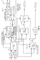
[0074]図1を参照すると、あるシステムの特定の例示的実施例が開示されており、概して100と示されている。システム100は、ネットワーク120を介して、第2のデバイス106に通信可能に結合された第1のデバイス104を含む。ネットワーク120は、1つまたは複数のワイヤレスネットワーク、1つまたは複数のワイヤードネットワーク、またはそれらの組み合わせを含み得る。
[0074] With reference to FIG. 1, certain exemplary embodiments of a system are disclosed, generally designated as 100. The
[0075]第1のデバイス104は、エンコーダ114、送信機110、1つまたは複数の入力インターフェース112、またはそれらの組み合わせを含み得る。入力インターフェース112の第1の入力インターフェースは、第1のマイクロフォン146に結合され得る。入力インターフェース(複数を含む)112の第2の入力インターフェースは、第2のマイクロフォン148に結合され得る。エンコーダ114は、チャネル間時間的ミスマッチ(ITM)アナライザ124、IPDモードセレクタ108、IPD推定器122、発話/音楽分類器129、LBアナライザ157、バンド幅拡張(BWE)アナライザ153、またはそれらの組み合わせを含み得る。エンコーダ114は、本明細書で説明されるような、複数のオーディオ信号をダウンミックスおよび符号化するように構成され得る。
[0075] The first device 104 may include an
[0076]第2のデバイス106は、デコーダ118および受信機170を含み得る。デコーダ118は、IPDモードアナライザ127、IPDアナライザ125、または両方を含み得る。デコーダ118は、複数のチャネルをアップミックスおよびレンダリングするように構成され得る。第2のデバイス106は、第1のラウドスピーカ142、第2のラウドスピーカ144、または両方に結合され得る。図1は、1つのデバイスがエンコーダを含みかつ別のデバイスがデコーダを含む例を例示しているが、代替の態様では、デバイスがエンコーダとデコーダとの両方を含み得ると理解されたい。
[0076] The second device 106 may include a
[0077]動作中、第1のデバイス104は、第1の入力インターフェースを介して第1のマイクロフォン146から第1のオーディオ信号130を受信し得、第2の入力インターフェースを介して第2のマイクロフォン148から第2のオーディオ信号132を受信し得る。第1のオーディオ信号130は、右チャネル信号または左チャネル信号のうちの一方に対応し得る。第2のオーディオ信号132は、右チャネル信号または左チャネル信号のうちのもう一方に対応し得る。サウンドソース152(例えば、ユーザ、スピーカ、環境雑音、楽器など)は、図1で示されるように、第2のマイクロフォン148よりも第1のマイクロフォン146に近い可能性がある。従って、サウンドソース152からのオーディオ信号は、入力インターフェース(複数を含む)112において、第1のマイクロフォン146を介して、第2のマイクロフォン148を介するよりも早い時間で受信され得る。複数のマイクロフォンを通じたマルチチャネル信号捕捉におけるこの自然遅延は、第1のオーディオ信号130と第2のオーディオ信号132との間のチャネル間時間的ミスマッチをもたらし得る。 [0077] During operation, the first device 104 may receive the first audio signal 130 from the first microphone 146 via the first input interface and the second microphone via the second input interface. A second audio signal 132 may be received from 148. The first audio signal 130 may correspond to either a right channel signal or a left channel signal. The second audio signal 132 may correspond to the other of the right channel signal and the left channel signal. The sound source 152 (eg, user, speaker, environmental noise, musical instrument, etc.) may be closer to the first microphone 146 than the second microphone 148, as shown in FIG. Thus, the audio signal from the sound source 152 can be received at the input interface (s) 112 via the first microphone 146 in a shorter time than via the second microphone 148. This natural delay in multi-channel signal acquisition through multiple microphones can result in a channel-to-channel time mismatch between the first audio signal 130 and the second audio signal 132.
[0078]チャネル間時間的ミスマッチアナライザ124は、第2のオーディオ信号132に関連する第1のオーディオ信号130のシフト(例えば、非因果的シフト)を示す、チャネル間時間的ミスマッチ値163(例えば、非因果的シフト値)を決定し得る。この例では、第1のオーディオ信号130は「ターゲット」信号と呼ばれ得、第2のオーディオ信号132は「基準」信号と呼ばれ得る。チャネル間時間的ミスマッチ値163の第1の値(例えば、正の値)は、第2のオーディオ信号132が第1のオーディオ信号130に対して遅延することを示し得る。チャネル間時間的ミスマッチ値163の第1の値(例えば、負の値)は、第1のオーディオ信号130が第2のオーディオ信号132に対して遅延することを示し得る。チャネル間時間的ミスマッチ値163の第3の値(例えば、0)は、第1のオーディオ信号130と第2のオーディオ信号132との間の時間的ずれがない(例えば、時間遅延がない)ことを示し得る。
[0078] The inter-channel
[0079]チャネル間時間的ミスマッチアナライザ124は、図4に関連してさらに説明されるように、第1のオーディオ信号130の第1のフレームと第2のオーディオ信号132の複数のフレームと(あるいは、逆もまた同様)の比較に基づいて、チャネル間時間的ミスマッチ値163、強度値150、または両方を決定し得る。チャネル間時間的ミスマッチアナライザ124は、図4に関連してさらに説明されるように、チャネル間時間的ミスマッチ値163に基づいて第1のオーディオ信号130(あるいは、第2のオーディオ信号132、または両方)を調整することによって、調整された第1のオーディオ信号130(あるいは、調整された第2のオーディオ信号132、または両方)を生成し得る。発話/音楽分類器129は、図4に関連してさらに説明されるように、第1のオーディオ信号130、第2のオーディオ信号132、または両方に基づいて発話/音楽決定パラメータ171を決定し得る。発話/音楽決定パラメータ171は、第1のオーディオ信号130の第1のフレームが発話により厳密に対応しているか、または音楽により厳密に対応しているか(従って、それらをより多く含んでいそうであるか)を示し得る。
[0079] The inter-channel
[0080]エンコーダ114は、コアタイプ167、コーダタイプ169、または両方を決定するように構成され得る。例えば、第1のオーディオ信号130の第1のフレームの符号化よりも前に、第1のオーディオ信号130の第2のフレームは、前のコアタイプ、前のコーダタイプ、または両方に基づいて符号化されている可能性がある。代替的に、コアタイプ167が前のコアタイプに対応し得るか、コーダタイプ169が前のコーダタイプに対応し得るか、または両方であり得る。代替の態様では、コアタイプ167が、予測されるコアタイプに対応し得るか、コーダタイプ169が、予測されるコーダタイプに対応し得るか、または両方であり得る。エンコーダ114は、図2に関連してさらに説明されるように、第1のオーディオ信号130および第2のオーディオ信号132に基づいて、予測されるコアタイプ、予測されるコーダタイプ、または両方を決定し得る。よって、コアタイプ167およびコーダタイプ169の値は、前のフレームを符号化するために使用されるそれぞれの値に設定され得るか、またはこのような値は、前のフレームを符号化するために使用される値とは無関係に予測され得る。
[0080] Encoder 114 may be configured to determine core type 167, coder type 169, or both. For example, prior to coding the first frame of the first audio signal 130, the second frame of the first audio signal 130 may be coded based on the previous core type, the previous coder type, or both. It may have been converted. Alternatively, the core type 167 can correspond to the previous core type, the coder type 169 can correspond to the previous coder type, or both. In an alternative embodiment, the core type 167 can correspond to the expected core type, the coder type 169 can correspond to the expected coder type, or both.
[0081]LBアナライザ157は、図2に関連してさらに説明されるように、第1のオーディオ信号130、第2のオーディオ信号132、または両方に基づいて、1つまたは複数のLBパラメータ159を決定するように構成される。LBパラメータ159は、コアサンプルレート(例えば、12.8kHzまたは16kHz)、ピッチ値、音声要素、音声アクティビティパラメータ、別のLB特性、またはそれらの組み合わせを含む。BWEアナライザ153は、図2に関連してさらに説明されるように、第1のオーディオ信号130、第2のオーディオ信号132、または両方に基づいて、1つまたは複数のBWEパラメータ155を決定するように構成される。BWEパラメータ155は、利得マッピングパラメータ、スペクトルマッピングパラメータ、チャネル間BWE基準チャネルインジケータ、またはそれらの組み合わせなどの、1つまたは複数のチャネル間BWEパラメータを含む。
[0081] The
[0082]IPDモードセレクタ108は、図4に関連してさらに説明されるように、チャネル間時間的ミスマッチ値163、強度値150、コアタイプ167、コーダタイプ169、LBパラメータ159、BWEパラメータ155、発話/音楽決定パラメータ171、またはそれらの組み合わせに基づいて、IPDモード156を選択し得る。IPDモード156は、分解能165、すなわち、IPD値を表すために使用されるビット数に対応し得る。IPD推定器122は、図4に関連してさらに説明されるように、分解能165を有するIPD値161を生成し得る。特定の実装では、分解能165は、IPD値161のカウントに対応する。例えば、第1のIPD値は、第1の周波数バンドに対応し得、第2のIPD値は、第2の周波数バンドに対応し得る、などである。この実装では、分解能165は、IPD値がIPD値161に含まれるべきである周波数バンドの数を示す。特定の態様では、分解能165は、位相値の範囲に対応する。例えば、分解能165は、位相値の範囲に含まれる値を表すためのビット数に対応する。
[0082] The IPD mode selector 108 has an interchannel temporal mismatch value of 163, an intensity value of 150, a core type of 167, a coder type of 169, an LB parameter of 159, and a BWE parameter of 155, as further described in connection with FIG. IPD mode 156 may be selected based on the utterance / music determination parameter 171 or a combination thereof. The IPD mode 156 may correspond to a resolution of 165, i.e., the number of bits used to represent the IPD value. The
[0083]特定の態様では、分解能165は、絶対IPD値を表すために使用されるべきビット数(例えば、量子化分解能)を示す。例えば、分解能165は、第1のビット数が(例えば、第1の量子化分解能が)第1の周波数バンドに対応する第1のIPD値の第1の絶対値を表すために使用されるべきであること、第2のビット数が(例えば、第2の量子化分解能が)第2の周波数バンドに対応する第2のIPD値の第2の絶対値を表すために使用されるべきであること、追加のビットが追加の周波数バンドに対応する追加の絶対IPD値を表すために使用されるべきであること、またはそれらの組み合わせを示し得る。IPD値161は、第1の絶対値、第2の絶対値、追加の絶対IPD値、またはそれらの組み合わせを含み得る。特定の態様では、分解能165は、フレームにわたるIPD値の時間的分散の量を表すために使用されるべきビット数を示す。例えば、第1のIPD値は、第1のフレームに関連付けられ得、第2のIPD値は、第2のフレームに関連付けられ得る。IPD推定器122は、第1のIPD値と第2のIPD値との比較に基づいて時間的分散の量を決定し得る。IPD値161は、時間的分散の量を示し得る。この態様では、分解能165は、時間的分散の量を表すために使用されるビット数を示す。エンコーダ114は、IPDモード156を示すIPDモードインジケータ116、分解能165、または両方を生成し得る。
[0083] In certain embodiments, resolution 165 indicates the number of bits to be used to represent an absolute IPD value (eg, quantization resolution). For example, resolution 165 should be used to represent the first absolute value of the first IPD value in which the number of first bits (eg, the first quantization resolution) corresponds to the first frequency band. That is, the number of second bits should be used to represent the second absolute value of the second IPD value corresponding to the second frequency band (eg, the second quantization resolution). It may indicate that an additional bit should be used to represent an additional absolute IPD value corresponding to an additional frequency band, or a combination thereof. The
[0084]エンコーダ114は、図2〜3に関連してさらに説明されるように、第1のオーディオ信号130、第2のオーディオ信号132、IPD値161、チャネル間時間的ミスマッチ値163、またはそれらの組み合わせに基づいて、サイドバンドビットストリーム164、ミッドバンドビットストリーム166、または両方を生成し得る。例えば、エンコーダ114は、調整された第1のオーディオ信号130(例えば、第1のアラインされたオーディオ信号)、第2のオーディオ信号132(例えば、第2のアラインされたオーディオ信号)、IPD値161、チャネル間時間的ミスマッチ値163、またはそれらの組み合わせに基づいて、サイドバンドビットストリーム164、ミッドバンドビットストリーム166、または両方を生成し得る。別の例では、エンコーダ114は、第1のオーディオ信号130、調整された第2のオーディオ信号132、IPD値161、チャネル間時間的ミスマッチ値163、またはそれらの組み合わせに基づいて、サイドバンドビットストリーム164、ミッドバンドビットストリーム166、または両方を生成し得る。エンコーダ114はまた、IPD値161を示すステレオキュービットストリーム162、チャネル間時間的ミスマッチ値163、IPDモードインジケータ116、コアタイプ167、コーダタイプ169、強度値150、発話/音楽決定パラメータ171、またはそれらの組み合わせを生成し得る。
[0084] The
[0085]送信機110は、ネットワーク120を介して、ステレオキュービットストリーム162、サイドバンドビットストリーム164、ミッドバンドビットストリーム166、またはそれらの組み合わせを第2のデバイス106に送信し得る。代替的にまたは追加的に、送信機110は、時間的に後のある時点においてさらに処理または復号するために、ローカルデバイスまたはネットワーク120のデバイスにおいて、ステレオキュービットストリーム162、サイドバンドビットストリーム164、ミッドバンドビットストリーム166、またはそれらの組み合わせを記憶し得る。分解能165がゼロビットより大きいものに対応するとき、チャネル間時間的ミスマッチ値163に加えてIPD値161は、デコーダ(例えば、デコーダ118またはローカルデコーダ)において、より細かいサブバンド調整(finer subband adjustments)を可能にし得る。分解能165がゼロビットに対応するとき、ステレオキュービットストリーム162は、より少ないビットを有し得るか、またはIPD以外のステレオキューパラメータ(複数を含む)を含むために利用可能なビットを有し得る。
[0085] The transmitter 110 may transmit the stereo cue bitstream 162, the
[0086]受信機170は、ネットワーク120を介して、ステレオキュービットストリーム162、サイドバンドビットストリーム164、ミッドバンドビットストリーム166、またはそれらの組み合わせを受信し得る。デコーダ118は、入力信号130、132の復号されたバージョンに対応する出力信号126、128を生成するために、ステレオキュービットストリーム162、サイドバンドビットストリーム164、ミッドバンドビットストリーム166、またはそれらの組み合わせに基づいて復号動作を行い得る。例えば、IPDモードアナライザ127は、ステレオキュービットストリーム162がIPDモードインジケータ116を含むこと、およびIPDモードインジケータ116がIPDモード156を示すことを決定し得る。IPDアナライザ125は、IPDモード156に対応する分解能165に基づいて、ステレオキュービットストリーム162からIPD値161を抽出し得る。デコーダ118は、図7に関連してさらに説明されるように、IPD値161、サイドバンドビットストリーム164、ミッドバンドビットストリーム166、またはそれらの組み合わせに基づいて、第1の出力信号126および第2の出力信号128を生成し得る。第2のデバイス106は、第1のラウドスピーカ142を介して第1の出力信号126を出力し得る。第2のデバイス106は、第2のラウドスピーカ144を介して第2の出力信号128を出力し得る。代替の例では、第1の出力信号126および第2の出力信号128は、ステレオ信号ペアとして単一の出力ラウドスピーカに送信され得る。
[0086] The receiver 170 may receive the stereo cue bitstream 162, the
[0087]よって、システム100は、エンコーダ114が様々な特性に基づいてIPD値161の分解能を動的に調整することが可能であり得る。例えば、エンコーダ114は、チャネル間時間的ミスマッチ値163、強度値150、コアタイプ167、コーダタイプ169、発話/音楽決定パラメータ171、またはそれらの組み合わせに基づいてIPD値の分解能を決定し得る。よって、エンコーダ114は、IPD値161が低分解能(例えば、ゼロ分解能)を有するとき、他の情報を符号化することが可能であるより多くのビットを使用し有し得、IPD値161がより高い分解能を有するとき、デコーダにおいてより細かいサブバンド調整のパフォーマンスを可能にし得る。
[0087] Therefore, the
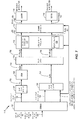
[0088]図2を参照すると、エンコーダ114の例示的実施例が示される。エンコーダ114は、ステレオキュー推定器206に結合されるチャネル間時間的ミスマッチアナライザ124を含む。ステレオキュー推定器206は、発話/音楽分類器129、LBアナライザ157、BWEアナライザ153、IPDモードセレクタ108、IPD推定器122、またはそれらの組み合わせを含み得る。
[0088] With reference to FIG. 2, an exemplary embodiment of the
[0089]変換器202は、チャネル間時間的ミスマッチアナライザ124を介して、ステレオキュー推定器206、サイドバンド信号生成器208、ミッドバンド信号生成器212、またはそれらの組み合わせに結合され得る。変換器204は、チャネル間時間的ミスマッチアナライザ124を介して、ステレオキュー推定器206、サイドバンド信号生成器208、ミッドバンド信号生成器212、またはそれらの組み合わせに結合され得る。サイドバンド信号生成器208は、サイドバンドエンコーダ210に結合され得る。ミッドバンド信号生成器212は、ミッドバンドエンコーダ214に結合され得る。ステレオキュー推定器206は、サイドバンド信号生成器208、サイドバンド信号エンコーダ210、ミッドバンド信号生成器212、またはそれらの組み合わせに結合され得る。
[0089] The
[0090]いくつかの例では、図1の第1のオーディオ信号130は、左チャネル信号を含み得、図1の第2のオーディオ信号132は、右チャネル信号を含み得る。時間領域左信号(Lt)290は、第1のオーディオ信号130に対応し得、時間領域右信号(Rt)292は、第2のオーディオ信号132に対応し得る。しかしながら、他の例では、第1のオーディオ信号130が右チャネル信号を含み得、第2のオーディオ信号132が左チャネル信号を含み得ることが理解されるべきである。このような例では、時間領域右信号(Rt)292は、第1のオーディオ信号130に対応し得、時間領域左信号(Lt)290は、第2のオーディオ信号132に対応し得る。図1〜4、図7〜8、および図10で例示される様々なコンポーネント(例えば、変換器、信号生成器、エンコーダ、推定器など)がハードウェア(例えば、回路専用)、ソフトウェア(例えば、プロセッサによって実行される命令)、またはそれらの組み合わせを使用して実装され得ることもまた理解されたい。 [0090] In some examples, the first audio signal 130 in FIG. 1 may include a left channel signal and the second audio signal 132 in FIG. 1 may include a right channel signal. The time domain left signal (L t ) 290 may correspond to the first audio signal 130, and the time domain right signal (R t ) 292 may correspond to the second audio signal 132. However, in another example, it should be understood that the first audio signal 130 may include a right channel signal and the second audio signal 132 may include a left channel signal. In such an example, the time domain right signal (R t ) 292 may correspond to the first audio signal 130 and the time domain left signal (L t ) 290 may correspond to the second audio signal 132. The various components exemplified in FIGS. 1-4, 7-8, and 10 (eg, converters, signal generators, encoders, estimators, etc.) are hardware (eg, circuit-only), software (eg, eg, circuits only). It should also be understood that instructions executed by a processor), or a combination thereof, can be used to implement them.
[0091]動作中、変換器202は、時間領域左信号(Lt)290において変換を行い得、変換器204は、時間領域右信号(Rt)292において変換を行い得る。変換器202、204は、周波数領域(またはサブバンド領域)信号を生成する変換動作を行い得る。制限はされないが、例として、変換器202、204は、離散フーリエ変換(DFT:Discrete Fourier Transform)動作、高速フーリエ変換(FFT:Fast Fourier Transform)動作などを行い得る。特定の実装では、(複素低遅延フィルタバンクなどのフィルタバンドを使用する)直交ミラーフィルタバンク(QMF:Quadrature Mirror Filterbank)動作は、入力信号290、292を複数のサブバンドに分割するために使用され、それらサブバンドは、別の周波数領域変換動作を使用して、周波数領域にコンバートされ得る。変換器202は、時間領域左信号(Lt)290を変換することによって、周波数領域左信号(Lfr(b))229を生成し得、変換器304は、時間領域右信号(Rt)292を変換することによって、周波数領域右信号(Rfr(b))231を生成し得る。
[0091] During operation, the
[0092]チャネル間時間的ミスマッチアナライザ124は、図4に関連して説明されるように、周波数領域左信号(Lfr(b))229および周波数領域右信号(Rfr(b))231に基づいて、チャネル間時間的ミスマッチ値163、強度値150、または両方を生成し得る。チャネル間時間的ミスマッチ値163は、周波数領域左信号(Lfr(b))229と周波数領域右信号(Rfr(b))231との間の時間的ミスマッチの推定値を提供し得る。チャネル間時間的ミスマッチ値163は、ICA値262を含み得る。チャネル間時間的ミスマッチアナライザ124は、周波数領域左信号(Lfr(b))229、周波数領域右信号(Rfr(b))231、およびチャネル間時間的ミスマッチ値163に基づいて、周波数領域左信号(Lfr(b))230と周波数領域右信号(Rfr(b))232とを生成し得る。例えば、チャネル間時間的ミスマッチアナライザ124は、ITM値264に基づいて周波数領域左信号(Lfr(b))229をシフトすることによって周波数領域左信号(Lfr(b))230を生成し得る。周波数領域右信号(Rfr(b))232は、周波数領域右信号(Rfr(b))231に対応し得る。代替的に、チャネル間時間的ミスマッチアナライザ124は、ITM値264に基づいて周波数領域右信号(Rfr(b))231をシフトすることによって周波数領域右信号(Rfr(b))232を生成し得る。周波数領域左信号(Lfr(b))230は、周波数領域左信号(Lfr(b))229に対応し得る。
[0092] The interchannel
[0093]特定の態様では、チャネル間時間的ミスマッチアナライザ124は、図4に関連して説明されるように、時間領域左信号(Lt)290および時間領域右信号(Rt)292に基づいて、チャネル間時間的ミスマッチ値163、強度値150、または両方を生成する。一態様では、チャネル間時間的ミスマッチ値163は、図4に関連して説明されるように、ICA値262よりもむしろITM値264を含む。チャネル間時間的ミスマッチアナライザ124は、時間領域左信号(Lt)290、時間領域右信号(Rt)292、およびチャネル間時間的ミスマッチ値163に基づいて、周波数領域左信号(Lfr(b))230および周波数領域右信号(Rfr(b))232を生成し得る。例えば、チャネル間時間的ミスマッチアナライザ124は、ICA値262に基づいて、時間領域左信号(Lt)290をシフトすることによって、調整された時間領域左信号(Lt)290を生成し得る。チャネル間時間的ミスマッチアナライザ124は、それぞれ、調整された時間領域左信号(Lt)290および時間領域右信号(Rt)292における変換を行うことによって、周波数領域左信号(Lfr(b))230と周波数領域右信号(Rfr(b))232とを生成し得る。代替的に、チャネル間時間的ミスマッチアナライザ124は、ICA値262に基づいて、時間領域右信号(Rt)292をシフトすることによって、調整された時間領域右信号(Rt)292を生成し得る。チャネル間時間的ミスマッチアナライザ124は、それぞれ、時間領域左信号(Lt)290および調整された時間領域右信号(Rt)292における変換を行うことによって、周波数領域左信号(Lfr(b))230および周波数領域右信号(Rfr(b))232を生成し得る。代替的に、チャネル間時間的ミスマッチアナライザ124は、ICA値262に基づいて時間領域左信号(Lt)290をシフトすることによって、調整された時間領域左信号(Lt)290を生成し、ICA値262に基づいて時間領域右信号(Rt)292をシフトすることによって調整された時間領域右信号(Rt)292を生成し得る。チャネル間時間的ミスマッチアナライザ124は、それぞれ、調整された時間領域左信号(Lt)290および調整された時間領域右信号(Rt)292における変換を行うことによって、周波数領域左信号(Lfr(b))230と周波数領域右信号(Rfr(b))232とを生成し得る。
[0093] In certain embodiments, the interchannel
[0094]ステレオキュー推定器206およびサイドバンド信号生成器208は、チャネル間時間的ミスマッチ値163、強度値150、または両方を、チャネル間時間的ミスマッチアナライザ124から各々受信し得る。ステレオキュー推定器206およびサイドバンド信号生成器208はまた、変換器202から周波数領域左信号(Lfr(b))230を受信し得るか、変換器204から周波数領域右信号(Rfr(b))232を受信し得るか、またはそれらの組み合わせであり得る。ステレオキュー推定器206は、周波数領域左信号(Lfr(b))230、周波数領域右信号(Rfr(b))232、チャネル間時間的ミスマッチ値163、強度値150、またはそれらの組み合わせに基づいてステレオキュービットストリーム162を生成し得る。例えば、ステレオキュー推定器206は、図4に関連して説明されるように、IPDモードインジケータ116、IPD値161、または両方を生成し得る。ステレオキュー推定器206は、代替的に、「ステレオキュービットストリーム生成器」とも呼ばれ得る。IPD値161は、周波数領域において、周波数領域左信号(Lfr(b))230と周波数領域右信号(Rfr(b))232との間の位相差の推定値を提供し得る。特定の態様では、ステレオキュービットストリーム162は、IIDなどのような追加の(または代替の)パラメータを含む。ステレオキュービットストリーム162は、サイドバンド信号生成器208に、およびサイドバンドエンコーダ210に提供され得る。
[0094] The stereo queue estimator 206 and the
[0095]サイドバンド信号生成器208は、周波数領域左信号(Lfr(b))230、周波数領域右信号(Rfr(b))232、チャネル間時間的ミスマッチ値163、IPD値161、またはそれらの組み合わせに基づいて、周波数領域サイドバンド信号(Sfr(b))234を生成し得る。特定の態様では、周波数領域サイドバンド信号234は、周波数領域ビン/バンドにおいて推定され、IPD値161は、複数のバンドに対応する。例えば、IPD値161の第1のIPD値は、第1の周波数バンドに対応し得る。サイドバンド信号生成器208は、第1のIPD値に基づいて第1の周波数バンド中の周波数領域左信号(Lfr(b))230における位相シフトを行うことによって、位相調整された周波数領域左信号(Lfr(b))230を生成し得る。サイドバンド信号生成器208は、第1のIPD値に基づいて第1の周波数バンド中の周波数領域右信号(Rfr(b))232において位相シフトを行うことによって、位相調整された周波数領域右信号(Rfr(b))232を生成し得る。このプロセスは、他の周波数バンド/ビンについて繰り返され得る。
[0095] The
[0096]位相調整された周波数領域左信号(Lfr(b))230は、c1(b)*Lfr(b)に対応し得、位相調整された周波数領域右信号(Rfr(b))232は、c2(b)*Rfr(b)に対応し得、ここで、Lfr(b)は周波数領域左信号(Lfr(b))230に対応し、Rfr(b)は周波数領域右信号(Rfr(b))232に対応し、c1(b)およびc2(b)はIPD値161に基づく複素数値である。特定の実装では、c1(b)=(cos(−γ)−i*sin(−γ))/20.5であり、c2(b)=(cos(IPD(b)−γ)+i*sin(IPD(b)−γ))/20.5であり、ここで、iは−1の平方根を意味する虚数であり、IPD(b)は特定のサブバンド(b)に関連付けられたIPD値161のうちの1つである。特定の態様では、IPDモードインジケータ116は、IPD値161が特定の分解能(例えば、0)を有することを示す。この態様では、位相調整された周波数領域左信号(Lfr(b))230は、周波数領域左信号(Lfr(b))230に対応し、一方、位相調整された周波数領域右信号(Rfr(b))232は、周波数領域右信号(Rfr(b))232に対応する。
[0096] The phase-adjusted frequency domain left signal (L fr (b)) 230 may correspond to c 1 (b) * L fr (b), and the phase-adjusted frequency domain right signal (R fr (b)). )) 232 may correspond to c 2 (b) * R fr (b), where L fr (b) corresponds to the frequency domain left signal (L fr (b)) 230 and R fr (b). ) Corresponds to the frequency domain right signal (R fr (b)) 232, and c 1 (b) and c 2 (b) are complex numerical values based on the
[0097]サイドバンド信号生成器208は、位相調整された周波数領域左信号(Lfr(b))230および位相調整された周波数領域右信号(Rfr(b))232に基づいて周波数領域サイドバンド信号(Sfr(b))234を生成し得る。周波数領域サイドバンド信号(Sfr(b))234は、(l(fr)−r(fr))/2と表され得、ここで、l(fr)は位相調整された周波数領域左信号(Lfr(b))230を含み、r(fr)は位相調整された周波数領域右信号(Rfr(b))232を含む。周波数領域サイドバンド信号(Sfr(b))234は、サイドバンドエンコーダ210に提供され得る。
The
[0098]ミッドバンド信号生成器212は、チャネル間時間的ミスマッチアナライザ124からチャネル間時間的ミスマッチ値163を受信し得るか、変換器202から周波数領域左信号(Lfr(b))230を受信し得るか、変換器204から周波数領域右信号(Rfr(b))232を受信し得るか、ステレオキュー推定器206からステレオキュービットストリーム162を受信し得るか、またはそれらの組み合わせであり得る。ミッドバンド信号生成器212は、サイドバンド信号生成器208に関連して説明されるように、位相調整された周波数領域左信号(Lfr(b))230および位相調整された周波数領域右信号(Rfr(b))232を生成し得る。ミッドバンド信号生成器212は、位相調整された周波数領域左信号(Lfr(b))230および位相調整された周波数領域右信号(Rfr(b))232に基づいて周波数領域ミッドバンド信号(Mfr(b))236を生成し得る。周波数領域ミッドバンド信号(Mfr(b))236は、(l(t)+r(t))/2と表され得、ここで、l(t)は位相調整された周波数領域左信号(Lfr(b))230を含み、r(t)は位相調整された周波数領域右信号(Rfr(b))232を含む。周波数領域ミッドバンド信号(Mfr(b))236は、サイドバンドエンコーダ210に提供され得る。周波数領域ミッドバンド信号(Mfr(b))236はまた、ミッドバンドエンコーダ214に提供され得る。
The midband signal generator 212 may receive the interchannel temporal mismatch value 163 from the interchannel
[0099]特定の態様では、ミッドバンド信号生成器212は、周波数領域ミッドバンド信号(Mfr(b))236を符号化するために使用されるべきフレームコアタイプ267、フレームコーダタイプ269、または両方を選択する。例えば、ミッドバンド信号生成器212は、フレームコアタイプ267として、代数符号励起予測(ACELP:algebraic code-excited linear prediction)コアタイプ、変換符号化励起(TCX:transform coded excitation)コアタイプ、または別のコアタイプを選択し得る。説明するように、ミッドバンド信号生成器212は、周波数領域ミッドバンド信号(Mfr(b))236が発話に対応することを発話/音楽分類器129が示すと決定したことに応答して、フレームコアタイプ267としてACELPコアタイプを選択し得る。代替的に、ミッドバンド信号生成器212は、周波数領域ミッドバンド信号(Mfr(b))236が非発話(例えば、音楽)に対応することを発話/音楽分類器129が示すと決定したことに応答して、フレームコアタイプ267としてTCXコアタイプを選択し得る。 [0099] In certain embodiments, the midband signal generator 212 is frame core type 267, frame coder type 269, or frame coder type 269 to be used to encode the frequency domain midband signal (M fr (b)) 236. Select both. For example, the midband signal generator 212 may have, as frame core type 267, an algebraic code-excited linear prediction (ACELP) core type, a transform coded excitation (TCX) core type, or another. You can choose the core type. As described, the midband signal generator 212 responds to the determination by the speech / music classifier 129 that the frequency domain midband signal (M fr (b)) 236 corresponds to the speech. The ACELP core type can be selected as the frame core type 267. Alternatively, the midband signal generator 212 has determined that the speech / music classifier 129 indicates that the frequency domain midband signal (M fr (b)) 236 corresponds to non-utterance (eg, music). In response to, the TCX core type may be selected as the frame core type 267.
[0100]LBアナライザ157は、図1のLBパラメータ159を決定するように構成される。LBパラメータ159は、時間領域左信号(Lt)290、時間領域右信号(Rt)292、または両方に対応する。特定の例では、LBパラメータ159は、コアサンプルレートを含む。特定の態様では、LBアナライザ157は、フレームコアタイプ267に基づいてコアサンプルレートを決定するように構成される。例えば、LBアナライザ157は、フレームコアタイプ267がACELPコアタイプに対応すると決定したことに応答して、コアサンプルレートとして第1のサンプルレート(例えば、12.8kHz)を選択するように構成される。代替的に、LBアナライザ157は、フレームコアタイプ267が非ACELPコアタイプ(例えば、TCXコアタイプ)に対応すると決定したことに応答して、コアサンプルレートとして第2のサンプルレート(例えば、16kHz)を選択するように構成される。代替の態様では、LBアナライザ157は、デフォルト値、ユーザ入力、構成設定、またはそれらの組み合わせに基づいて、コアサンプルレートを決定するように構成される。
[0100] The
[0101]特定の態様では、LBパラメータ159は、ピッチ値、音声アクティビティパラメータ、音声要素、またはそれらの組み合わせを含む。ピッチ値は、時間領域左信号(Lt)290に対応する差分ピッチ期間または絶対ピッチ期間、時間領域右信号(Rt)292、あるいは両方を示し得る。音声アクティビティパラメータは、発話が時間領域左信号(Lt)290において検出されるか、時間領域右信号(Rt)292において検出されるか、または両方において検出されるかを示し得る。音声要素(例えば、0.0から1.0までの値)は、時間領域左信号(Lt)290、時間領域右信号(Rt)292、または両方の有声/無声(voiced/unvoiced)の性質(例えば、強い有声、弱い有声、弱い無声、または強い無声)を示す。 [0101] In certain embodiments, the LB parameter 159 comprises a pitch value, a voice activity parameter, a voice element, or a combination thereof. The pitch value may indicate a differential pitch period or an absolute pitch period corresponding to the time domain left signal (L t ) 290, a time domain right signal (R t ) 292, or both. The voice activity parameter may indicate whether the utterance is detected at the time domain left signal (L t ) 290, at the time domain right signal (R t ) 292, or both. The voice element (eg, a value from 0.0 to 1.0) can be time domain left signal (L t ) 290, time domain right signal (R t ) 292, or both voiced / unvoiced. Indicates a property (eg, strong voiced, weak voiced, weak unvoiced, or strong unvoiced).
[0102]BWEアナライザ153は、時間領域左信号(Lt)290、時間領域右信号(Rt)292、または両方に基づいて、BWEパラメータ155を決定するように構成される。BWEパラメータ155は、利得マッピングパラメータ、スペクトルマッピングパラメータ、チャネル間BWE基準チャネルインジケータ、またはそれらの組み合わせを含む。例えば、BWEアナライザ153は、ハイバンド信号と合成ハイバンド信号との比較に基づいて、利得マッピングパラメータを決定するように構成される。特定の態様では、ハイバンド信号および合成ハイバンド信号は、時間領域左信号(Lt)290に対応する。特定の態様では、ハイバンド信号および合成ハイバンド信号は、時間領域右信号(Rt)292に対応する。特定の例では、BWEアナライザ153は、ハイバンド信号と合成ハイバンド信号との比較に基づいて、スペクトルマッピングパラメータを決定するように構成される。説明するように、BWEアナライザ153は、合成ハイバンド信号に利得パラメータを適用することによって、利得調整された合成信号を生成するように、および利得調整された合成信号とハイバンド信号との比較に基づいてスペクトルマッピングパラメータを生成するように構成される。スペクトルマッピングパラメータは、スペクトルチルトを示す。 [0102] The BWE analyzer 153 is configured to determine the BWE parameter 155 based on the time domain left signal (L t ) 290, the time domain right signal (R t) 292, or both. The BWE parameter 155 includes a gain mapping parameter, a spectral mapping parameter, a channel-to-channel BWE reference channel indicator, or a combination thereof. For example, the BWE analyzer 153 is configured to determine the gain mapping parameters based on a comparison of the highband signal with the synthetic highband signal. In certain embodiments, the highband and synthetic highband signals correspond to a time domain left signal (Lt ) 290. In certain embodiments, the highband and synthetic highband signals correspond to a time domain right signal (Rt ) 292. In a particular example, the BWE analyzer 153 is configured to determine spectral mapping parameters based on a comparison of the highband signal with the synthetic highband signal. As described, the BWE analyzer 153 applies gain parameters to the combined highband signal to produce a gain-adjusted composite signal, and for comparison between the gain-adjusted composite signal and the highband signal. It is configured to generate spectral mapping parameters based on it. The spectral mapping parameter indicates spectral tilt.
[0103]ミッドバンド信号生成器212は、周波数領域ミッドバンド信号(Mfr(b))236が発話に対応することを発話/音楽分類器129が示すと決定したことに応答して、フレームコーダタイプ269として一般的な信号コーディング(GSC)コーダタイプまたは非GSCコーダタイプを選択し得る。例えば、ミッドバンド信号生成器212は、周波数領域ミッドバンド信号(Mfr(b))236が高いスペクトルスパース性(high spectral sparseness)(例えば、スパース性閾値よりも高い)に対応すると決定したことに応答して、非GSCコーダタイプ(例えば、修正された離散コサイン変換(MDCT:modified discrete cosine transform))を選択し得る。代替的に、ミッドバンド信号生成器212は、周波数領域ミッドバンド信号(Mfr(b))236が非スパーススペクトル(例えば、スパース性閾値よりも低い)に対応すると決定したことに応答して、GSCコーダタイプを選択し得る。 [0103] The midband signal generator 212 is a frame coder in response to the utterance / music classifier 129 determining that the frequency domain midband signal (M fr (b)) 236 corresponds to the utterance. A general signal coding (GSC) coder type or a non-GSC coder type can be selected as the type 269. For example, the midband signal generator 212 has determined that the frequency domain midband signal (M fr (b)) 236 corresponds to high spectral sparseness (eg, higher than the sparseness threshold). In response, a non-GSC coder type (eg, modified discrete cosine transform (MDCT)) may be selected. Alternatively, the midband signal generator 212 responds by determining that the frequency domain midband signal (M fr (b)) 236 corresponds to a non-sparse spectrum (eg, below the sparsity threshold). GSC coder type can be selected.
[0104]ミッドバンド信号生成器212は、フレームコアタイプ267、フレームコーダタイプ269、または両方に基づいて符号化するために、ミッドバンドエンコーダ214に周波数領域ミッドバンド信号(Mfr(b))236を提供し得る。フレームコアタイプ267、フレームコーダタイプ269、または両方は、ミッドバンドエンコーダ214によって符号化されるべき周波数領域ミッドバンド信号(Mfr(b))236の第1のフレームに関連付けられ得る。フレームコアタイプ267は、前のフレームコアタイプ268としてメモリに記憶され得る。フレームコーダタイプ269は、前のフレームコーダタイプ270としてメモリに記憶され得る。ステレオキュー推定器206は、図4に関連して説明されるように、周波数領域ミッドバンド信号(Mfr(b))236の第2のフレームに関連してステレオキュービットストリーム162を決定するために、前のフレームコアタイプ268、前のフレームコーダタイプ270、または両方を使用し得る。図中の様々なコンポーネントのグループは例示を簡略化するためのものであり、制限されるものではないことが理解されるべきである。例えば、発話/音楽分類器129は、ミッド信号生成パスに沿って任意のコンポーネント中に含まれ得る。説明するように、発話/音楽分類器129は、ミッドバンド信号生成器212に含まれ得る。ミッドバンド信号生成器212は、発話/音楽決定パラメータを生成し得る。発話/音楽決定パラメータは、図1の発話/音楽決定パラメータ171としてメモリに記憶され得る。ステレオキュー推定器206は、図4に関連して説明されるように、周波数領域ミッドバンド信号(Mfr(b))236の第2のフレームに関連してステレオキュービットストリーム162を決定するために、発話/音楽決定パラメータ171、LBパラメータ159、BWEパラメータ155、またはそれらの組み合わせを使用するように構成される。
[0104] The midband signal generator 212 has a frequency domain midband signal (M fr (b)) 236 in the
[0105]サイドバンドエンコーダ210は、ステレオキュービットストリーム162、周波数領域サイドバンド信号(Sfr(b))234、および周波数領域ミッドバンド信号(Mfr(b))236に基づいて、サイドバンドビットストリーム164を生成し得る。ミッドバンドエンコーダ214は、周波数領域ミッドバンド信号(Mfr(b))236を符号化することによって、ミッドバンドビットストリーム166を生成し得る。特定の例では、サイドバンドエンコーダ210およびミッドバンドエンコーダ214は、それぞれ、サイドバンドビットストリーム164およびミッドバンドビットストリーム166を生成するために、ACELPエンコーダ、TCXエンコーダ、または両方を含み得る。低バンドに関して、周波数領域サイドバンド信号(Sfr(b))334は、変換領域コーディング技法を使用して符号化され得る。高バンドに関して、周波数領域サイドバンド信号(Sfr(b))234は、(量子化されるか、または量子化されていない)前のフレームのミッドバンド信号からの予測値(prediction)として表され得る。
[0105] The
[0106]ミッドバンドエンコーダ214は、周波数領域ミッドバンド信号(Mfr(b))236を、符号化の前に任意の他の変換/時間領域に変換し得る。例えば、周波数領域ミッドバンド信号(Mfr(b))236は、時間領域に戻されるか、またはコーディングのためにMDCT領域に変換される。
[0106] The
[0107]図2は、前に符号化されたフレームのコアタイプおよび/またはコーダタイプがIPDモードを決定するために使用され、したがって、ステレオキュービットストリーム162中のIPD値の分解能を決定する、エンコーダ114の例を例示する。代替の態様では、エンコーダ114は、前のフレームからの値よりもむしろ、予測されるコアおよび/またはコーダタイプを使用する。例えば、図3は、予測されるコアタイプ368、予測されるコーダタイプ370、または両方に基づいてステレオキュー推定器206がステレオキュービットストリーム162を決定することができる、エンコーダ114の例示的実施例を描く。
[0107] FIG. 2 shows that the core type and / or coder type of the previously encoded frame is used to determine the IPD mode and thus determines the resolution of the IPD value in the stereo cue bitstream 162. An example of the
[0108]エンコーダ114は、プリプロセッサ318に結合されたダウンミキサ320を含む。プリプロセッサ318は、マルチプレクサ(MUX)316を介して、ステレオキュー推定器206に結合される。ダウンミキサ320は、チャネル間時間的ミスマッチ値163に基づいて、時間領域左信号(Lt)290および時間領域右信号(Rt)292をダウンミックスすることによって、推定された時間領域ミッドバンド信号(Mt)396を生成し得る。例えば、ダウンミキサ320は、図2に関連して説明されるように、チャネル間時間的ミスマッチ値163に基づいて、時間領域左信号(Lt)290を調整することによって、調整された時間領域左信号(Lt)290を生成し得る。ダウンミキサ320は、調整された時間領域左信号(Lt)290および時間領域右信号(Rt)292に基づいて、推定された時間領域ミッドバンド信号(Mt)396を生成し得る。推定された時間領域ミッドバンド信号(Mt)396は、(l(t)+r(t))/2と表され得、ここで、l(t)は調整された時間領域左信号(Lt)290を含み、r(t)は時間領域右信号(Rt)292を含む。別の例では、ダウンミキサ320は、図2に関連して説明されるように、チャネル間時間的ミスマッチ値163に基づいて、時間領域右信号(Rt)292を調整することによって、調整された時間領域右信号(Rt)292を生成し得る。ダウンミキサ320は、時間領域左信号(Lt)290および調整された時間領域右信号(Rt)292に基づいて、推定された時間領域ミッドバンド信号(Mt)396を生成し得る。推定された時間領域ミッドバンド信号(Mt)396は、(l(t)+r(t))/2と表され得、ここで、l(t)は時間領域左信号(Lt)290を含み、r(t)は調整された時間領域右信号(Rt)292を含む。
[0108]
[0109]代替的に、ダウンミキサ320は、時間領域中でよりもむしろ、周波数領域中で動作し得る。説明するように、ダウンミキサ320は、チャネル間時間的ミスマッチ値163に基づいて、周波数領域左信号(Lfr(b))229および周波数領域右信号(Rfr(b))231をダウンミックスすることによって、推定された周波数領域ミッドバンド信号Mfr(b)336を生成し得る。例えば、ダウンミキサ320は、図2に関連して説明されるように、チャネル間時間的ミスマッチ値163に基づいて、周波数領域左信号(Lfr(b))230および周波数領域右信号(Rfr(b))232を生成し得る。ダウンミキサ320は、周波数領域左信号(Lfr(b))230および周波数領域右信号(Rfr(b))232に基づいて、推定された周波数領域ミッドバンド信号Mfr(b)336を生成し得る。推定された周波数領域ミッドバンド信号Mfr(b)336は、(l(t)+r(t))/2と表され得、ここで、l(t)は周波数領域左信号(Lfr(b))230を含み、r(t)は周波数領域右信号(Rfr(b))232を含む。 [0109] Alternatively, the downmixer 320 may operate in the frequency domain rather than in the time domain. As described, the downmixer 320 downmixes the frequency domain left signal (L fr (b)) 229 and the frequency domain right signal (R fr (b)) 231 based on the interchannel temporal mismatch value 163. Thereby, the estimated frequency domain midband signal M fr (b) 336 can be generated. For example, the down mixer 320 has a frequency domain left signal (L fr (b)) 230 and a frequency domain right signal (R fr ) based on the interchannel temporal mismatch value 163, as described in connection with FIG. (B)) 232 can be produced. The downmixer 320 generates an estimated frequency domain midband signal M fr (b) 336 based on the frequency domain left signal (L fr (b)) 230 and the frequency domain right signal (R fr (b)) 232. Can be. The estimated frequency domain midband signal M fr (b) 336 can be expressed as (l (t) + r (t)) / 2, where l (t) is the frequency domain left signal (L fr (b). )) 230, where r (t) includes the frequency domain right signal (R fr (b)) 232.
[0110]ダウンミキサ320は、プリプロセッサ318に、推定された時間領域ミッドバンド信号(Mt)396(または推定された周波数領域ミッドバンド信号Mfr(b)336を提供し得る。プリプロセッサ318は、ミッドバンド信号生成器212に関連して説明されるように、ミッドバンド信号に基づいて、予測されるコアタイプ368、予測されるコーダタイプ370、または両方を決定し得る。例えば、プリプロセッサ318は、ミッドバンド信号の発話/音楽分類、ミッドバンド信号のスペクトルスパース性、または両方に基づいて、予測されるコアタイプ368、予測されるコーダタイプ370、または両方を決定し得る。特定の態様では、プリプロセッサ318は、ミッドバンド信号の発話/音楽分類に基づいて、予測される発話/音楽決定パラメータを決定し、予測される発話/音楽決定パラメータ、ミッドバンド信号のスペクトルスパース性、または両方に基づいて、予測されるコアタイプ368、予測されるコーダタイプ370、または両方を決定する。ミッドバンド信号は、推定された時間領域ミッドバンド信号(Mt)396または推定された周波数領域ミッドバンド信号Mfr(b)336)を含み得る。
[0110] The downmixer 320 may provide the
[0111]プリプロセッサ318は、予測されるコアタイプ368、予測されるコーダタイプ370、予測される発話/音楽決定パラメータ、またはそれらの組み合わせを、MUX316に提供し得る。MUX316は、ステレオキュー推定器206への出力を、予測されるコーディング情報(例えば、予測されるコアタイプ368、予測されるコーダタイプ370、予測される発話/音楽決定パラメータ、またはそれらの組み合わせ)、または周波数領域ミッドバンド信号Mfr(b)236の前の符号化されたフレームに関連付けられた前のコーディング情報(例えば、前のフレームコアタイプ268、前のフレームコーダタイプ270、前のフレームの発話/音楽決定パラメータ、またはそれらの組み合わせ)から選択し得る。例えば、MUX316は、デフォルト値、ユーザ入力に対応する値、または両方に基づいて、予測されるコーディング情報または前のコーディング情報から選択し得る。
[0111] The
[0112]図2に関連して説明されるように、ステレオキュー推定器206に、前のコーディング情報(例えば、前のフレームコアタイプ268、前のフレームコーダタイプ270、前のフレームの発話/音楽決定パラメータ、またはそれらの組み合わせ)を提供することは、予測されるコーディング情報(例えば、予測されるコアタイプ368、予測されるコーダタイプ370、予測される発話/音楽決定パラメータ、またはそれらの組み合わせ)を決定するために使用されるであろうリソース(例えば、時間、処理サイクル、または両方)を節約し得る。逆に、第1のオーディオ信号130および/または第2のオーディオ信号132の特徴に多くのフレーム間バリエーションが存在するとき、予測されるコーディング情報(例えば、予測されるコアタイプ368、予測されるコーダタイプ370、予測される発話/音楽決定パラメータ、またはそれらの組み合わせ)は、ミッドバンド信号生成器212によって選択された、コアタイプ、コーダタイプ、発話/音楽決定パラメータ、またはそれらの組み合わせにより明確に対応し得る。よって、(例えば、MUX316への入力に基づいて)ステレオキュー推定器206への出力を、前のコーディング情報または予測されるコーディング情報間で動的に切り替えることは、リソースの使用量および正確性を保つことを可能にし得る。 [0112] As described in connection with FIG. 2, the stereo cue estimator 206 is equipped with previous coding information (eg, previous frame core type 268, previous frame coder type 270, previous frame speech / music). Providing decision parameters (or combinations thereof) provides predicted coding information (eg, predicted core type 368, predicted coder type 370, predicted speech / music decision parameters, or a combination thereof). Can save resources (eg, time, processing cycles, or both) that will be used to determine. Conversely, when there are many interframe variations in the features of the first audio signal 130 and / or the second audio signal 132, the predicted coding information (eg, the predicted core type 368, the predicted coder). Type 370, predicted speech / music determination parameters, or a combination thereof) is clearly addressed by the core type, coder type, speech / music determination parameters, or a combination thereof, selected by the midband signal generator 212. Can be. Thus, dynamically switching the output to the stereo queue estimator 206 (eg, based on the input to the MUX 316) between previous or expected coding information can reduce resource usage and accuracy. It may be possible to keep.
[0113]図4を参照すると、ステレオキュー推定器206の例示的実施例が示されている。ステレオキュー推定器206は、チャネル間時間的ミスマッチアナライザ124に結合され得、それは、左信号(L)490の第1のフレームと右信号(R)492の複数のフレームとの比較に基づいて、相関信号145を決定し得る。特定の態様では、左信号(L)490は、時間領域左信号(Lt)290に対応し、一方、右信号(R)492は、時間領域右信号(Rt)292に対応する。代替の態様では、左信号(L)490は、周波数領域左信号(Lfr(b))229に対応し、一方、右信号(R)492は、周波数領域右信号(Rfr(b))231に対応する。
[0113] With reference to FIG. 4, an exemplary embodiment of the stereo queue estimator 206 is shown. The stereo cue estimator 206 may be coupled to the interchannel
[0114]右信号(R)492の複数のフレームの各々は、特定のチャネル間時間的ミスマッチ値に対応し得る。例えば、右信号(R)492の第1のフレームは、チャネル間時間的ミスマッチ値163に対応し得る。相関信号145は、左信号(L)490の第1のフレームと右信号(R)492の複数のフレームの各々との間の相関を示し得る。
[0114] Each of the plurality of frames of the right signal (R) 492 may correspond to a specific interchannel temporal mismatch value. For example, the first frame of the right signal (R) 492 may correspond to the interchannel temporal mismatch value 163. The
[0115]代替的には、チャネル間時間的ミスマッチアナライザ124は、右信号(R)492の第1のフレームと左信号(L)490の複数のフレームとの比較に基づいて、相関信号145を決定し得る。この態様では、左信号(L)490の複数のフレームの各々は、特定のチャネル間時間的ミスマッチ値に対応する。例えば、左信号(L)490の第1のフレームは、チャネル間時間的ミスマッチ値163に対応し得る。相関信号145は、右信号(R)492の第1のフレームと左信号(L)490の複数のフレームの各々との間の相関を示し得る。
[0115] Alternatively, the interchannel
[0116]チャネル間時間的ミスマッチアナライザ124は、相関信号145が左信号(L)490の第1のフレームと右信号(R)492の第1のフレームとの間で最も高い相関を示すと決定したことに基づいて、チャネル間時間的ミスマッチ値163を選択し得る。例えば、チャネル間時間的ミスマッチアナライザ124は、相関信号145のピークが右信号(R)492の第1のフレームに対応すると決定したことに応答して、チャネル間時間的ミスマッチ値163を選択し得る。チャネル間時間的ミスマッチアナライザ124は、左信号(L)490の第1のフレームと右信号(R)492の第1のフレームとの間の相関のレベルを示す、強度値150を決定し得る。例えば、強度値150は、相関信号145のピークの最高値に対応し得る。チャネル間時間的ミスマッチ値163は、左信号(L)490および右信号(R)492が、それぞれ、時間領域左信号(Lt)290および時間領域右信号(Rt)292などの時間領域信号であるとき、ICA値262に対応し得る。代替的に、チャネル間時間的ミスマッチ値163は、左信号(L)490および右信号(R)492が、それぞれ、周波数領域左信号(Lfr)229および周波数領域右信号(Rfr)231などの周波数領域信号であるとき、ITM値264に対応し得る。チャネル間時間的ミスマッチアナライザ124は、図2に関連して説明されるように、左信号(L)490、右信号(R)492、およびチャネル間時間的ミスマッチ値163に基づいて、周波数領域左信号(Lfr(b))230および周波数領域右信号(Rfr(b))232を生成し得る。チャネル間時間的ミスマッチアナライザ124は、ステレオキュー推定器206に、周波数領域左信号(Lfr(b))230、周波数領域右信号(Rfr(b))232、チャネル間時間的ミスマッチ値163、強度値150、またはそれらの組み合わせを提供し得る。
[0116] The interchannel
[0117]発話/音楽分類器129は、様々な発話/音楽分類技法を使用して、周波数領域左信号(Lfr)230(または、周波数領域右信号(Lfr)232)に基づいて発話/音楽決定パラメータ171を生成し得る。例えば、発話/音楽分類器129は、周波数領域左信号(Lfr)230(または、周波数領域右信号(Lfr)232)に関連付けられた線形予測係数(LPC:linear prediction coefficients)を決定し得る。発話/音楽分類器129は、LPCを使用して周波数領域左信号(Lfr)230(または、周波数領域右信号(Lfr)232)を逆フィルタリングすることによって残差信号を生成し得、その残差信号の残りのエネルギ(residual energy)が閾値を満たすかどうかを決定することに基づいて、発話または音楽として周波数領域左信号(Lfr)230(または、周波数領域右信号(Lfr)232)を分類し得る。発話/音楽決定パラメータ171は、周波数領域左信号(Lfr)230(または周波数領域右信号(Lfr)232)が発話として分類されるか、または音楽として分類されるかを示し得る。特定の態様では、ステレオキュー推定器206は、図2に関連して説明されるように、ミッドバンド信号生成器212から発話/音楽決定パラメータ171を受信し、ここで、発話/音楽決定パラメータ171は、前のフレームの発話/音楽決定パラメータに対応する。別の態様では、ステレオキュー推定器206は、図3に関連して説明されるように、MUX316から発話/音楽決定パラメータ171を受信し、ここで、発話/音楽決定パラメータ171は、前のフレームの発話/音楽決定パラメータまたは予測される発話/音楽決定パラメータに対応する。
[0117] The utterance / music classifier 129 uses a variety of utterance / music classification techniques to speak / speak based on the frequency domain left signal (L fr ) 230 (or frequency domain right signal (L fr ) 232). The music determination parameter 171 can be generated. For example, the speech / music classifier 129 may determine the linear prediction coefficients (LPC) associated with the frequency domain left signal (L fr ) 230 (or frequency domain right signal (L fr) 232). .. The speech / music classifier 129 may generate a residual signal by reverse filtering the frequency domain left signal (L fr ) 230 (or frequency domain right signal (L fr) 232) using the LPC. Frequency domain left signal (L fr ) 230 (or frequency domain right signal (L fr ) 232) as speech or music based on determining whether the residual energy of the residual signal meets the threshold. ) Can be classified. The utterance / music determination parameter 171 may indicate whether the frequency domain left signal (L fr ) 230 (or frequency domain right signal (L fr ) 232) is classified as utterance or music. In certain embodiments, the stereo cue estimator 206 receives an utterance / music determination parameter 171 from the midband signal generator 212, where the utterance / music determination parameter 171 is described in connection with FIG. Corresponds to the speech / music determination parameters of the previous frame. In another aspect, the stereo cue estimator 206 receives the utterance / music determination parameter 171 from the
[0118]LBアナライザ157は、LBパラメータ159を決定するように構成される。例えば、LBアナライザ157は、図2に関連して説明されるように、コアサンプルレート、ピッチ値、音声アクティビティパラメータ、音声要素、またはそれらの組み合わせを決定するように構成される。BWEアナライザ153は、図2に関連して説明されるように、BWEパラメータ155を決定するように構成される。
[0118] The
[0119]IPDモードセレクタ108は、チャネル間時間的ミスマッチ値163、強度値150、コアタイプ167、コーダタイプ169、発話/音楽決定パラメータ171、LBパラメータ159、BWEパラメータ155、またはそれらの組み合わせに基づいて、複数のIPDモードからIPDモード156を選択し得る。コアタイプ167は、図2の前のフレームコアタイプ268、または図3の予測されるコアタイプ368に対応し得る。コーダタイプ169は、図2の前のフレームコーダタイプ270、または図3の予測されるコーダタイプ370に対応し得る。複数のIPDモードは、第1の分解能456に対応する第1のIPDモード465、第2の分解能476に対応する第2のIPDモード467、1つまたは複数の追加のIPDモード、またはそれらの組み合わせを含み得る。第1の分解能456は、第2の分解能476よりも高くなり得る。例えば、第1の分解能456は、第2の分解能476に対応する第2のビット数よりも高いビット数に対応し得る。
[0119] The IPD mode selector 108 is based on an interchannel temporal mismatch value 163,
[0120]IPDモードのいくつかの例となる制限されない例が、下記に説明される。IPDモードセレクタ108は、制限はされないが、チャネル間時間的ミスマッチ値163、強度値150、コアタイプ167、コーダタイプ169、LBパラメータ159、BWEパラメータ155、および/または発話/音楽決定パラメータ171を含む要素の任意の組み合わせに基づいて、IPDモード156を選択し得ることが理解されるべきである。特定の態様では、IPDモードセレクタ108は、IPD値161がオーディオ品質により大きい影響を与える可能性があることを、チャネル間時間的ミスマッチ値163、強度値150、コアタイプ167、LBパラメータ159、BWEパラメータ155、コーダタイプ169、または発話/音楽決定パラメータ171が示すとき、IPDモード156として第1のIPDモード465を選択する。
[0120] Some unrestricted examples of IPD mode are described below. The IPD mode selector 108 includes, but is not limited to, an interchannel temporal mismatch value 163, an
[0121]特定の態様では、IPDモードセレクタ108は、チャネル間時間的ミスマッチ値163が差分閾値(例えば、0)を満たす(例えば、それに等しい)との決定に応答して、IPDモード156として第1のIPDモード465を選択する。IPDモードセレクタ108は、チャネル間時間的ミスマッチ値163が差分閾値(例えば、0)を満たす(例えば、それに等しい)との決定に応答して、IPD値161がオーディオ品質により大きい影響を与える可能性があると決定し得る。代替的に、IPDモードセレクタ108は、チャネル間時間的ミスマッチ値163が差分閾値(例えば、0)を満たさない(例えば、それに等しくない)と決定したこと応答して、IPDモード156として第2のIPDモード467を選択し得る。
[0121] In certain embodiments, the IPD mode selector 108 sets the IPD mode 156 as IPD mode 156 in response to a determination that the interchannel temporal mismatch value 163 meets (eg, is equal to) a difference threshold (eg, 0). Select 1 IPD mode 465. The IPD mode selector 108 may have an
[0122]特定の態様では、IPDモードセレクタ108は、チャネル間時間的ミスマッチ値163が差分閾値(例えば、0)を満たさず(例えば、それに等しくない)、かつ強度値150が強度閾値を満たす(例えば、それよりも大きい)との決定に応答して、IPDモード156として第1のIPDモード465を選択する。IPDモードセレクタ108は、チャネル間時間的ミスマッチ値163が差分閾値(例えば、0)を満たさず(例えば、それに等しくない)、かつ強度値150が強度閾値を満たす(例えば、それよりも大きい)と決定したことに応答して、IPD値161がオーディオ品質により大きい影響を与える可能性があると決定し得る。代替的に、IPDモードセレクタ108は、チャネル間時間的ミスマッチ値163が差分閾値(例えば、0)を満たさず(例えば、それに等しくない)、かつ強度値150が強度閾値を満たさない(例えば、それ以下である)との決定に応答して、IPDモード156として第2のIPDモード467を選択し得る。
[0122] In certain embodiments, the IPD mode selector 108 has an interchannel temporal mismatch value 163 that does not meet the difference threshold (eg, 0) (eg, not equal to it) and an intensity value of 150 that meets the intensity threshold (eg, not equal to it). For example, in response to the determination (larger than that), the first IPD mode 465 is selected as the IPD mode 156. The IPD mode selector 108 states that the interchannel temporal mismatch value 163 does not meet the difference threshold (eg, 0) (eg, is not equal to it) and the
[0123]特定の態様では、IPDモードセレクタ108は、チャネル間時間的ミスマッチ値163が差分閾値(例えば、閾値)よりも小さいと決定したことに応答して、チャネル間時間的ミスマッチ値163が差分閾値を満たすと決定する。この態様では、IPDモードセレクタ108は、チャネル間時間的ミスマッチ値163が差分閾値以上であると決定したことに応答して、チャネル間時間的ミスマッチ値163が差分閾値を満たさないと決定する。 [0123] In a particular embodiment, the IPD mode selector 108 has an interchannel temporal mismatch value 163 differential in response to determining that the interchannel temporal mismatch value 163 is less than a difference threshold (eg, threshold). Determine to meet the threshold. In this aspect, the IPD mode selector 108 determines that the inter-channel temporal mismatch value 163 does not satisfy the difference threshold in response to the determination that the inter-channel temporal mismatch value 163 is greater than or equal to the difference threshold.
[0124]特定の態様では、IPDモードセレクタ108は、コーダタイプ169が非GSCコーダタイプに対応すると決定したことに応答して、IPDモード156として第1のIPDモード465を選択する。IPDモードセレクタ108は、コーダタイプ169が非GSCコーダタイプに対応すると決定したことに応答して、IPD値161がオーディオ品質により大きい影響を与える可能性があると決定し得る。代替的に、IPDモードセレクタ108は、コーダタイプ169がGSCコーダタイプに対応すると決定したことに応答して、IPDモード156として第2のIPDモード467を選択し得る。
[0124] In a particular embodiment, the IPD mode selector 108 selects the first IPD mode 465 as the IPD mode 156 in response to the determination that the coder type 169 corresponds to a non-GSC coder type. The IPD mode selector 108 may determine that the
[0125]特定の態様では、IPDモードセレクタ108は、コアタイプ167がTCXコアタイプに対応するかまたはコアタイプ167がACELPコアタイプに対応し、かつコーダタイプ169が非GSCコーダタイプに対応すると決定したことに応答して、IPDモード156として第1のIPDモード465を選択する。IPDモードセレクタ108は、コアタイプ167がTCXコアタイプに対応するかまたはコアタイプ167がACELPコアタイプに対応し、かつコーダタイプ169が非GSCコーダタイプに対応すると決定したことに応答して、IPD値161がオーディオ品質により大きい影響を与える可能性があると決定し得る。代替的に、IPDモードセレクタ108は、コアタイプ167がACELPコアタイプに対応し、かつコーダタイプ169がGSCコーダタイプに対応すると決定したことに応答して、IPDモード156として第2のIPDモード467を選択し得る。
[0125] In certain embodiments, the IPD mode selector 108 determines that the core type 167 corresponds to the TCX core type or the core type 167 corresponds to the ACELP core type and the coder type 169 corresponds to the non-GSC coder type. In response to the above, the first IPD mode 465 is selected as the IPD mode 156. The IPD mode selector 108 responds to the determination that the core type 167 corresponds to the TCX core type or the core type 167 corresponds to the ACELP core type and the coder type 169 corresponds to the non-GSC coder type. It can be determined that the
[0126]特定の態様では、IPDモードセレクタ108は、周波数領域左信号(Lfr)230(または周波数領域右信号(Lfr)232)が非発話(例えば、音楽)として分類されたことを、発話/音楽決定パラメータ171が示すと決定したことに応答して、IPDモード156として第1のIPDモード465を選択する。IPDモードセレクタ108は、周波数領域左信号(Lfr)230(または周波数領域右信号(Lfr)232)が非発話(例えば、音楽)として分類されたことを、発話/音楽決定パラメータ171が示すと決定したことに応答して、IPD値161がオーディオ品質により大きい影響を与える可能性があると決定し得る。代替的に、IPDモードセレクタ108は、周波数領域左信号(Lfr)230(または周波数領域右信号(Lfr)232)が発話として分類されたことを、発話/音楽決定パラメータ171が示すと決定したことに応答して、IPDモード156として第2のIPDモード467を選択し得る。
[0126] In certain embodiments, the IPD mode selector 108 indicates that the frequency domain left signal (L fr ) 230 (or frequency domain right signal (L fr ) 232) has been classified as non-utterance (eg, music). The first IPD mode 465 is selected as the IPD mode 156 in response to the determination that the utterance / music determination parameter 171 indicates. The IPD mode selector 108 indicates that the frequency domain left signal (L fr ) 230 (or frequency domain right signal (L fr ) 232) has been classified as non-spoken (eg, music) by the speech / music determination parameter 171. In response to the determination, it can be determined that the
[0127]特定の態様では、IPDモードセレクタ108は、LBパラメータ159がコアサンプルレートを含み、コアサンプルレートが第1のコアサンプルレート(例えば、16kHz)に対応すると決定したことに応答して、IPDモード156として第1のIPDモード465を選択する。IPDモードセレクタ108は、コアサンプルレートが第1のコアサンプルレート(例えば、16kHz)に対応すると決定したことに応答して、IPD値161がオーディオ品質により大きい影響を与える可能性があると決定し得る。代替的に、IPDモードセレクタ108は、コアサンプルレートが第2のコアサンプルレート(例えば、12kHz)に対応すると決定したことに応答して、IPDモード156として第2のIPDモード467を選択し得る。
[0127] In a particular embodiment, the IPD mode selector 108 responds to the determination that the LB parameter 159 comprises a core sample rate and that the core sample rate corresponds to a first core sample rate (eg, 16 kHz). The first IPD mode 465 is selected as the IPD mode 156. The IPD mode selector 108 determines that the
[0128]特定の態様では、IPDモードセレクタ108は、LBパラメータ159が特定のパラメータを含み、その特定のパラメータの値が第1の閾値を満たすと決定したことに応答して、IPDモード156として第1のIPDモード465を選択する。特定のパラメータは、ピッチ値、音声パラメータ、音声要素、利得マッピングパラメータ、スペクトルマッピングパラメータ、またはチャネル間BWE基準チャネルインジケータを含み得る。IPDモードセレクタ108は、特定のパラメータが第1の閾値を満たすと決定したことに応答して、IPD値161がオーディオ品質により大きい影響を与える可能性があると決定し得る。代替的に、IPDモードセレクタ108は、特定のパラメータが第1の閾値を満たさないと決定したことに応答して、IPDモード156として第2のIPDモード467を選択し得る。
[0128] In a particular embodiment, the IPD mode selector 108 is as IPD mode 156 in response to the determination that the LB parameter 159 comprises a particular parameter and the value of that particular parameter meets the first threshold. Select the first IPD mode 465. Specific parameters may include pitch values, audio parameters, audio elements, gain mapping parameters, spectral mapping parameters, or interchannel BWE reference channel indicators. The IPD mode selector 108 may determine that the
[0129]下記の表1は、IPDモード156を選択する、上述された例示的態様の概要を提供する。しかしながら、説明される態様は制限されるとみなされるべきではないと理解されたい。代替の実装では、表1の行に示される条件の同じセットは、表1中に示されるものとは異なるIPDモードを選択するようにIPDモードセレクタ108導き得る。加えて、代替の実装では、より多い、より少ない、および/または異なる要素が考慮され得る。さらに、決定表(decision table)は、代替的な態様において、より多くのまたはより少ない行を含み得る。 [0129] Table 1 below provides an overview of the exemplary embodiments described above for selecting IPD mode 156. However, it should be understood that the embodiments described should not be considered restricted. In an alternative implementation, the same set of conditions shown in the rows of Table 1 may lead the IPD mode selector 108 to select a different IPD mode than those shown in Table 1. In addition, more, less, and / or different factors may be considered in alternative implementations. In addition, the decision table may contain more or fewer rows in an alternative embodiment.

[0130]IPDモードセレクタ108は、選択されたIPDモード156(例えば、第1のIPDモード465または第2のIPDモード467)を示すIPDモードインジケータ116をIPD推定器122に提供する。特定の態様では、第2のIPDモード467に関連付けられた第2の分解能476は、IPD値161が特定の値(例えば、ゼロ)に設定されるべきであること、IPD値161の各々が特定の値(例えば、ゼロ)に設定されるべきであること、またはIPD値161がステレオキュービットストリーム162にないことを示す特定の値(例えば、ゼロ)を有する。IPDモード465に関連付けられた第1の分解能456は、特定の値(例えば、ゼロ)とは異なる(例えば、ゼロよりも大きい)別の値を有し得る。この態様では、IPD推定器122は、選択されたIPDモード156が第2のIPDモード467に対応すると決定したことに応答して、IPD値161を特定の値(例えば、ゼロ)に設定するか、IPD値161の各々を特定の値(例えば、ゼロ)に設定するか、またはステレオキュービットストリーム162にIPDモード161を含むことを控える。代替的に、IPD推定器122は、本明細書で説明されるように、選択されたIPDモード156が第1のIPDモード465に対応すると決定したことに応答して、第1のIPD値461を決定し得る。
[0130] The IPD mode selector 108 provides the
[0131]IPD推定器122は、周波数領域左信号(Lfr(b))230、周波数領域右信号(Rfr(b))232、チャネル間時間的ミスマッチ値163、またはそれらの組み合わせに基づいて、第1のIPD値461を決定し得る。IPD推定器122は、チャネル間時間的ミスマッチ値163に基づいて、左信号(L)490または右信号(R)492のうちの少なくとも1つを調整することによって、第1のアラインされた信号および第2のアラインされた信号を生成し得る。第1のアラインされた信号は、第2のアラインされた信号と時間的にアラインされ得る。例えば、第1のアラインされた信号の第1のフレームは、左信号(L)490の第1のフレームに対応し得、第2のアラインされた信号の第1のフレームは、右信号(R)492の第1のフレームに対応し得る。第1のアラインされた信号の第1のフレームは、第2のアラインされた信号の第1のフレームにアラインされ得る。
[0131] The
[0132]IPD推定器122は、チャネル間時間的ミスマッチ値163に基づいて、左信号(L)490または右信号(R)492のうちの1つが時間的に遅れているチャネル(temporally lagging channel)に対応すると決定し得る。例えば、IPD推定器122は、チャネル間時間的ミスマッチ値163が特定の値(例えば、0)を満たさない(例えば、それよりも小さい)と決定したことに応答して、左信号(L)490が時間的に遅れているチャネルに対応することを決定し得る。IPD推定器122は、時間的に遅れているチャネルを非因果的に調整し得る。例えば、IPD推定器122は、左信号(L)490が時間的に遅れているチャネルに対応すると決定したことに応答して、チャネル間時間的ミスマッチ値163に基づいて、左信号(L)490を非因果的に調整することによって、調整された信号を生成し得る。第1のアラインされた信号は、調整された信号に対応し得、第2のアラインされた信号は、右信号(R)492(例えば、調整されていない信号)に対応し得る。
[0132] The
[0133]特定の態様では、IPD推定器122は、周波数領域中で位相回転動作を行うことによって、第1のアラインされた信号(例えば、第1の位相回転された周波数領域信号)と、第2のアラインされた信号(例えば、第2の位相回転された周波数領域信号)とを生成する。例えば、IPD推定器122は、左信号(L)490(または、調整された信号)において第1の変換を行うことによって、第1のアラインされた信号を生成し得る。特定の態様では、IPD推定器122は、右信号(R)492において第2の変換を行うことによって、第2のアラインされた信号を生成する。代替の態様では、IPD推定器122は、第2のアラインされた信号として右信号(R)492を指定する。
[0133] In a particular embodiment, the
[0134]IPD推定器122は、左信号(L)490(または第1のアラインされた信号)の第1のフレームと、右信号(R)492(または第2のアラインされた信号)の第1のフレームとに基づいて第1のIPD値461を決定し得る。IPD推定器122は、複数の周波数サブバンドの各々に関連付けられた相関信号を決定し得る。例えば、第1の相関信号は、左信号(L)490の第1のフレームの第1のサブバンドと、右信号(R)492の第1のフレームの第1のサブバンドに適用された複数の位相シフトとに基づき得る。複数の位相シフトの各々は、特定のIPD値に対応し得る。IPD推定器122は、特定の位相シフトが右信号(R)492の第1のフレームの第1のサブバンドに適用されるとき、左信号(L)490の第1のサブバンドが右信号(R)492の第1のフレームの第1のサブバンドとの最も高い相関を有することを、第1の相関信号が示すと決定し得る。特定の位相シフトは、第1のIPD値に対応し得る。IPD推定器122は、第1のサブバンドに関連付けられた第1のIPD値を、第1のIPD値461に加算し得る。同様に、IPD推定器122は、1つまたは複数の追加のサブバンドに対応する1つまたは複数の追加のIPD値を、第1のIPD値461に加算し得る。特定の態様では、第1のIPD値461に関連付けられたサブバンドの各々は、異なっている。代替の態様では、IPD値461に関連付けられたいくつかのサブバンドは、オーバーラップする。第1のIPD値461は、第1の分解能456(例えば、最も高い利用可能な分解能)に関連付けられ得る。IPD推定器122によって考慮される周波数サブバンドは、同じサイズであり得るか、または異なるサイズであり得る。
[0134] The
[0135]特定の態様では、IPD推定器122は、IPDモード156に対応する分解能165を有するように第1のIPD値461を調整することによって、IPD値161を生成する。特定の態様では、IPD推定器122は、分解能165が第1の分解能456以上であると決定したことに応答して、IPD値161が第1のIPD値461と同じであることを決定する。例えば、IPD推定器122は、第1のIPD値461を調整することを控え得る。よって、IPDモード156が第1のIPD値461を表すのに十分な分解能(例えば、高分解能)に対応するとき、第1のIPD値461は、調整することなく送信され得る。代替的に、IPD推定器122は、分解能165が第1の分解能456よりも低いと決定したことに応答して、第1のIPD値461の分解能を減少させ得るIPD値161を生成し得る。よって、IPDモード156が第1のIPD値461を表すのに不十分な分解能(例えば、低分解能)に対応するとき、第1のIPD値461は、送信前にIPD値161を生成するために調整され得る。
[0135] In certain embodiments, the
[0136]特定の態様では、分解能165は、図1に関連して説明されるように、絶対IPD値を表すために使用されるべきビット数を示す。IPD値161は、第1のIPD値461の絶対値のうちの1つまたは複数を含み得る。例えば、IPD推定器122は、第1のIPD値461の第1の値の絶対値に基づいて、IPD値161の第1の値を決定し得る。IPD値161の第1の値は、第1のIPD値461の第1の値と同じ数端数バンドに関連付けられ得る。
[0136] In certain embodiments, the resolution 165 indicates the number of bits to be used to represent the absolute IPD value, as described in connection with FIG. The
[0137]特定の態様では、分解能165は、図1に関連して説明されるように、フレームにわたってIPD値の時間的分散の量を表すために使用されるべきビット数を示す。IPD推定器122は、第1のIPD値461と第2のIPD値との比較に基づいて、IPD値161を決定し得る。第1のIPD値461は、ある特定のオーディオフレームに関連付けられ得、第2のIPD値は、別のオーディオフレームに関連付けられ得る。IPD値161は、第1のIPD値461と第2のIPD値との間の時間的分散の量を示し得る。
[0137] In certain embodiments, resolution 165 indicates the number of bits to be used to represent the amount of temporal dispersion of IPD values over a frame, as described in connection with FIG. The
[0138]IPD値の分解能を低減する、いくつかの例となる制限されない例が下記に説明される。様々な他の技法がIPD値の分解能を低減することが理解されるべきである。 [0138] Some exemplary, unrestricted examples of reducing the resolution of IPD values are described below. It should be understood that various other techniques reduce the resolution of IPD values.
[0139]特定の態様では、IPD推定器122は、IPD値のターゲット分解能165が、決定されたIPD値の第1の分解能456よりも低いことを決定する。すなわち、IPD推定器122は、決定されているIPD値によって占有されるビット数よりも、IPDを表すために利用可能なより少ないビットが存在することを決定し得る。これに応答して、IPD推定器122は、第1のIPD値461を平均化することによってグループIPD値を生成し得、そのグループIPD値を示すためにIPD値161を設定し得る。よって、IPD値161は、複数のIPD値(例えば、8)の第1の分解能456(例えば、24ビット)よりも低い分解能(例えば、3ビット)を有する単一のIPD値を示し得る。
[0139] In a particular embodiment, the
[0140]特定の態様では、IPD推定器122は、分解能165が第1の分解能456よりも低いと決定したことに応答して、予測量子化に基づいてIPD値161を決定する。例えば、IPD推定器122は、前に符号化されたフレームに対応するIPD値(例えば、IPD値161)に基づいて、予測されるIPD値を決定するためにベクトル量子化器を使用し得る。IPD推定器122は、予測されるIPD値と第1のIPD値461との比較に基づいて、補正IPD値(correction IPD values)を決定し得る。IPD値161は、補正IPD値を示し得る。(デルタに対応する)IPD値161の各々は、第1のIPD値461よりも低い分解能を有し得る。よって、IPD値161は、第1の分解能456よりも低い分解能を有し得る。
[0140] In a particular embodiment, the
[0141]特定の態様では、IPD推定器122は、分解能165が第1の分解能456よりも低いと決定したことに応答して、IPD値161のうちのいくつかを表すために、他のものよりもより少ないビットを使用する。例えば、IPD推定器122は、IPD値161の対応サブセットを生成するために、第1のIPD値461のサブセットの分解能を低減し得る。引き下げられた分解能(lowered resolution)を有する第1のIPD値461のサブセットは、特定の例では、特定の周波数バンド(例えば、より高い周波数バンドまたはより低い周波数バンド)に対応する。
[0141] In certain embodiments, the
[0142]特定の態様では、IPD推定器122は、分解能165が第1の分解能456よりも低いと決定したことに応答して、IPD値161のうちのいくつかを表すために、他のものよりもより少ないビットを使用する。例えば、IPD推定器122は、IPD値161の対応サブセットを生成するために、第1のIPD値461のサブセットの分解能を低減し得る。第1のIPD値461のサブセットは、特定の周波数バンド(例えば、より高い周波数バンド)に対応し得る。
[0142] In certain embodiments, the
[0143]特定の態様では、分解能165は、IPD値161のカウントに対応する。IPD推定器122は、そのカウントに基づいて、第1のIPD値461のサブセットを選択し得る。例えば、サブセットのサイズは、カウント以下であり得る。特定の態様では、IPD推定器122は、第1のIPD値461に含まれるIPD値の数がカウントよりも大きいと決定したことに応答して、第1のIPD値461から特定の周波数バンド(例えば、より高い周波数バンド)に対応するIPD値を選択する。IPD値161は、第1のIPD値461の選択されたサブセットを含み得る。
[0143] In certain embodiments, the resolution 165 corresponds to a count of IPD values 161. The
[0144]特定の態様では、IPD推定器122は、分解能165が第1の分解能456よりも低いと決定したことに応答して、多項式関数(polynomial coefficient)に基づいてIPD値161を決定する。例えば、IPD推定器122は、第1のIPD値461に近い多項式(例えば、最も適合する多項式)を決定し得る。IPD推定器122は、IPD値161を生成するために多項式関数を量子化し得る。よって、IPD値161は、第1の分解能456よりも低い分解能を有し得る。
[0144] In a particular embodiment, the
[0145]特定の態様では、IPD推定器122は、分解能165が第1の分解能456よりも低いと決定したことに応答して、第1のIPD値461のサブセットを含むためにIPD値161を生成する。第1のIPD値461のサブセットは、特定の周波数バンド(例えば、高優先度の周波数バンド)に対応し得る。IPD推定器122は、第1のIPD値461の第2のサブセットの分解能を低減することによって、1つまたは複数の追加のIPD値を生成し得る。IPD値161は、追加のIPD値を含み得る。第1のIPD値461の第2のサブセットは、特定の周波数バンド(例えば、中優先度の周波数バンド(medium priority frequency bands))に対応し得る。第1のIPD値461の第3のサブセットは、第3の特定の周波数バンド(例えば、低優先度の周波数バンド)に対応し得る。IPD値161は、第3の特定の周波数バンドに対応するIPD値を除外し得る。特定の態様では、低周波数バンドなどのオーディオ品質により大きい影響を与える周波数バンドは、高優先度を有する。いくつかの例では、どの周波数バンドが高優先度であるかは、(例えば、発話/音楽決定パラメータ171に基づいて)フレームに含まれるオーディオコンテンツのタイプに依存し得る。説明するように、発話データは低い周波数範囲に主に位置し得るが、音楽データは周波数範囲にわたってより分散され得るため、低周波数バンドは、発話フレームに関して優先され得るが、音楽フレームに関しては優先されない可能性がある。
[0145] In a particular embodiment, the
[0146]ステレオキュー推定器206は、チャネル間時間的ミスマッチ値163、IPD値161、IPDモードインジケータ116、またはそれらの組み合わせを示す、ステレオキュービットストリーム162を生成し得る。IPD値161は、第1の分解能456以上の特定の分解能を有し得る。その特定の分解能(例えば、3ビット)は、IPDモード156に関連付けられた図1の分解能165(例えば、低分解能)に対応し得る。
[0146] The stereo cue estimator 206 may generate a stereo cue bitstream 162 indicating an interchannel temporal mismatch value 163, an
[0147]よって、IPD推定器122は、チャネル間時間的ミスマッチ値163、強度値150、コアタイプ167、コーダタイプ169、発話/音楽決定パラメータ171、またはそれらの組み合わせに基づいてIPD値161の分解能を動的に調整し得る。IPD値161は、IPD値161がオーディオ品質により大きい影響を与えると予測されるとき、より高い分解能を有し得、IPD値161がオーディオ品質にそれほど影響を与えないと予測されるとき、より低い分解能を有し得る。
[0147] Thus, the
[0148]図5を参照すると、動作の方法が示され、概して500と示されている。方法500は、図1のIPDモードセレクタ108、エンコーダ114、第1のデバイス104、システム100、またはそれらの組み合わせによって行われ得る。
[0148] With reference to FIG. 5, a method of operation is shown, generally shown as 500.
[0149]方法500は、502において、チャネル間時間的ミスマッチ値が0に等しいかどうかを決定することを含む。例えば、図1のIPDモードセレクタ108は、図1のチャネル間時間的ミスマッチ値163が0に等しいかどうかを決定し得る。
[0149]
[0150]方法500はまた、チャネル間時間的ミスマッチが0に等しくないと決定したことに応答して、504において、強度値が強度閾値よりも小さいかどうかを決定することを含む。例えば、図1のIPDモードセレクタ108は、図1のチャネル間時間的ミスマッチ値163が0に等しくないと決定したことに応答して、図1の強度値150が強度閾値よりも小さいかどうかを決定し得る。
[0150]
[0151]方法500は、強度値が強度閾値以上であると決定したことに応答して、506において、「ゼロ分解能」を選択することをさらに含む。例えば、図1のIPDモードセレクタ108は、図1の強度値150が強度閾値以上であると決定したことに応答して、図1のIPDモード156として第1のIPDモードを選択し得、ここで、第1のIPDモードは、IPD値を表すためのステレオキュービットストリーム162のゼロビットを使用することに対応する。
[0151]
[0152]特定の態様では、図1のIPDモードセレクタ108は、発話/音楽決定パラメータ171が特定の値(例えば、1)を有すると決定したことに応答して、IPDモード156として第1のIPDモードを選択する。例えば、IPDモードセレクタ108は、下記の疑似コードに基づいてIPDモード156を選択する。 [0152] In a particular embodiment, the IPD mode selector 108 of FIG. 1 is the first as IPD mode 156 in response to determining that the utterance / music determination parameter 171 has a particular value (eg, 1). Select the IPD mode. For example, the IPD mode selector 108 selects the IPD mode 156 based on the following pseudo code.
[0153]ここで、「hStereoDft→no_ipd_flag」は、IPDモード156に対応し、第1の値(例えば、1)は、第1のIPDモード(例えば、ゼロ分解能モードまたは低分解能モード)を示し、第2の値(例えば、0)は、第2のIPDモード(例えば、高分解能モード)を示し、「hStereoDft→gainIPD_sm」は、強度値150に対応し、「sp_aud_decision0」は、発話/音楽決定パラメータ171に対応する。IPDモードセレクタ108は、高分解能(例えば、「hStereoDft→no_ipd_flag = 0」)に対応する第2のIPDモードにIPDモード156を初期化する。IPDモードセレクタ108は、発話/音楽決定パラメータ171(例えば、「sp_aud_decision0」)に少なくとも部分的に基づいて、ゼロ分解能に対応する第1のIPDモードにIPDモード156を設定する。特定の態様では、IPDモードセレクタ108は、強度値150が閾値(例えば、0.75f)を満たし(例えば、それ以上である)、発話/音楽決定パラメータ171が特定の値(例えば、1)を有するか、コアタイプ167が特定の値を有し、コーダタイプ169が特定の値を有するか、LBパラメータ159の1つまたは複数のパラメータ(例えば、コアサンプルレート、ピッチ値、音声アクティビティパラメータ、または音声要素)が特定の値を有するか、BWEパラメータ155の1つまたは複数のパラメータ(例えば、利得マッピングパラメータ、スペクトルマッピングパラメータ、またはチャネル間基準チャネルインジケータ)が特定の値を有するか、またはそれらの組み合わせであると決定したことに応答して、IPDモード156として第1のIPDモードを選択するように構成される。 [0153] Here, "hStereoDft → no_ipd_flag" corresponds to IPD mode 156, and the first value (for example, 1) indicates the first IPD mode (for example, zero resolution mode or low resolution mode). A second value (eg, 0) indicates a second IPD mode (eg, high resolution mode), "hStereoDft → gainIPD_sm" corresponds to an intensity value of 150, and "sp_aud_decision0" is an utterance / music determination parameter. Corresponds to 171. The IPD mode selector 108 initializes the IPD mode 156 to the second IPD mode corresponding to the high resolution (for example, “hStereoDft → no_ipd_flag = 0”). The IPD mode selector 108 sets the IPD mode 156 as the first IPD mode corresponding to zero resolution, at least partially based on the utterance / music determination parameter 171 (eg, "sp_aud_decision0"). In certain embodiments, the IPD mode selector 108 has an intensity value of 150 satisfying a threshold (eg, 0.75f) (eg, greater than or equal to) and a speech / music determination parameter 171 of a particular value (eg, 1). Have, core type 167 has a specific value, coder type 169 has a specific value, or one or more parameters of LB parameter 159 (eg, core sample rate, pitch value, voice activity parameter, or The audio element) has a specific value, or one or more of the BWE parameters 155 (eg, a gain mapping parameter, a spectral mapping parameter, or an interchannel reference channel indicator) has a specific value, or theirs. The first IPD mode is configured to be selected as the IPD mode 156 in response to the determination of the combination.
[0154]方法500はまた、504において強度値が強度閾値よりも小さいと決定したことに応答して、508において低分解能を選択することを含む。例えば、図1のIPDモードセレクタ108は、図1の強度値150が強度値よりも小さいと決定したことに応答して、図1のIPDモード156として第2のIPDモードを選択し得、ここで、第2のIPDモードは、ステレオキュービットストリーム162においてIPD値を表すために低分解能(例えば、3ビット)を使用することに対応する。特定の態様では、IPDモードセレクタ108は、強度値150が強度閾値よりも小さいか、発話/音楽決定パラメータ171が特定の値(例えば、1)を有するか、LBパラメータ159のうちの1つまたは複数が特定の値を有するか、BWEパラメータ155のうちの少なくとも1つが特定の値を有するか、またはそれらの組み合わせであると決定したことに応答して、IPDモード156として第2のIPDモードを選択するように構成される。
[0154]
[0155]方法500は、502においてチャネル間時間的ミスマッチが0に等しいと決定したことに応答して、510においてコアタイプがACELPコアタイプに対応するかどうかを決定することをさらに含む。例えば、図1のIPDモードセレクタ108は、図1のチャネル間時間的ミスマッチ値163が0に等しいと決定したことに応答して、図1のコアタイプ167がACELPコアタイプに対応するかどうかを決定し得る。
[0155]
[0156]方法500はまた、510においてコアタイプがACELPコアタイプに対応しないと決定したことに応答して、512において高分解能を選択することを含む。例えば、図1のIPDモードセレクタ108は、図1のコアタイプ167がACELPコアタイプに対応しないと決定したことに応答して、図1のIPDモード156として第3のIPDモードを選択し得る。第3のIPDモードは、高分解能(例えば、16ビット)に関連付けられ得る。
[0156]
[0157]方法500はさらに、510においてコアタイプがACELPコアタイプに対応すると決定したことに応答して、コーダタイプが514においてGSCコアタイプに対応するかどうかを決定することをさらに含む。例えば、図1のIPDモードセレクタ108は、図1のコアタイプ167がACELPコアタイプに対応すると決定したことに応答して、図1のコーダタイプ169がGSCコーダタイプに対応するかどうかを決定し得る。
[0157]
[0158]方法500はまた、514においてコーダタイプがGSCコーダタイプに対応すると決定したことに応答して、508に進むことを含む。例えば、図1のIPDモードセレクタ108は、図1のコーダタイプ169がGSCコアタイプに対応すると決定したことに応答して、図1のIPDモード156として第2のIPDモードを選択し得る。
[0158]
[0159]方法500は、514においてコーダタイプがGSCコーダタイプに対応しないと決定したことに応答して、512に進むことをさらに含む。例えば、図1のIPDモードセレクタ108は、図1のコーダタイプ169がGSCコーダタイプに対応しないと決定したことに応答して、図1のIPDモード156として第3のIPDモードを選択し得る。
[0159]
[0160]方法500は、IPDモード156を決定する例示的実施例に対応する。方法500に例示される一連の動作は、説明を容易にするためのものであることが理解されるべきである。いくつかの実装では、IPDモード156は、図5に示されているものより多い、より少ない、および/または異なる動作を含む、異なる一連の動作に基づいて選択され得る。IPDモード156は、チャネル間時間的ミスマッチ値163、強度値150、コアタイプ167、コーダタイプ169、または発話/音楽決定パラメータ171の任意の組み合わせに基づいて選択され得る。
[0160]
[0161]図6を参照すると、動作の方法が示されており、概して600と示されている。方法600は、図1のIPD推定器122、IPDモードセレクタ108、チャネル間時間的ミスマッチアナライザ124、エンコーダ114、送信機110、システム100、図2のステレオキュー推定器206、サイドバンドエンコーダ210、ミッドバンドエンコーダ214、またはそれらの組み合わせによって行われ得る。
[0161] With reference to FIG. 6, a method of operation is shown, generally shown as 600.
[0162]602において、方法600は、デバイスにおいて、第1のオーディオ信号と第2のオーディオ信号との間の時間的ずれを示すチャネル間時間的ミスマッチ値を決定することを含む。例えば、チャネル間時間的ミスマッチアナライザ124は、図1および図4に関連して説明されるように、チャネル間時間的ミスマッチ値163を決定し得る。チャネル間時間的ミスマッチ値163は、第1のオーディオ信号130と第2のオーディオ信号132との間の時間的ずれ(例えば、時間遅延)を示し得る。
[0162] In 602,
[0163]604において、方法600はまた、デバイスにおいて、少なくともチャネル間時間的ミスマッチ値に基づいてIPDモードを選択することを含む。例えば、IPDモードセレクタ108は、図1および図4に関連して説明されるように、少なくともチャネル間時間的ミスマッチ値163に基づいてIPDモード156を決定し得る。
[0163] In 604, the
[0164]606において、方法600は、デバイスにおいて、第1のオーディオ信号と第2のオーディオ信号とに基づいてIPD値を決定することをさらに含む。例えば、IPD推定器122は、図1および図4に関連して説明されるように、第1のオーディオ信号130および第2のオーディオ信号132に基づいてIPD値161を決定し得る。IPD値161は、選択されたIPDモード156に対応する分解能165を有し得る。
[0164] In 606,
[0165]608において、方法600はまた、デバイスにおいて、第1のオーディオ信号および第2のオーディオ信号に基づいてミッドバンド信号を生成することを含む。例えば、ミッドバンド信号生成器212は、図2に関連して説明されるように、第1のオーディオ信号130および第2のオーディオ信号132に基づいて周波数領域ミッドバンド信号(Mfr(b))236を生成し得る。
[0165] In 608, the
[0166]610において、方法600は、デバイスにおいて、ミッドバンド信号に基づいてミッドバンドビットストリームを生成することをさらに含む。例えば、ミッドバンドエンコーダ214は、図2に関連して説明されるように、周波数領域ミッドバンド信号(Mfr(b))236に基づいてミッドバンドビットストリーム166を生成し得る。
[0166] At 610,
[0167]612において、方法600はまた、デバイスにおいて、第1のオーディオ信号および第2のオーディオ信号に基づいてサイドバンド信号を生成することを含む。例えば、サイドバンド信号生成器208は、図2に関連して説明されるように、第1のオーディオ信号130および第2のオーディオ信号132に基づいて周波数領域サイドバンド信号(Sfr(b))234を生成し得る。
[0167] In 612, the
[0168]614において、方法600は、デバイスにおいて、サイドバンド信号に基づいてサイドバンドビットストリームを生成することをさらに含む。例えば、サイドバンドエンコーダ210は、図2に関連して説明されるように、周波数領域サイドバンド信号(Sfr(b))234に基づいてサイドバンドビットストリーム164を生成し得る。
[0168] In 614,
[0169]616において、方法600はまた、デバイスにおいて、IPD値を示すステレオキュービットストリームを生成することを含む。例えば、ステレオキュー推定器206は、図2〜図4に関連して説明されるように、IPD値161を示すステレオキュービットストリーム162を生成し得る。
[0169] In 616,
[0170]618において、方法600は、デバイスからサイドバンドビットストリームを送信することをさらに含む。例えば、図1の送信機110は、サイドバンドビットストリーム164を送信し得る。送信機110は、ミッドバンドビットストリーム166またはステレオキュービットストリーム162のうちの少なくとも1つを追加で送信し得る。
[0170] In 618,
[0171]よって、方法600は、チャネル間時間的ミスマッチ値163に少なくとも部分的に基づいて、IPD値161の分解能を動的に調整することを可能にし得る。より大きいビット数は、IPD値161がオーディオ品質により大きい影響を与えるとき、IPD値161を符号化するために使用され得る。
[0171] Thus,
[0172]図7を参照すると、デコーダ118の特定の実装を例示する図が示されている。符号化されたオーディオ信号は、デコーダ118のデマルチプレクサ(DEMUX)702に提供される。符号化されたオーディオ信号は、ステレオキュービットストリーム162、サイドバンドビットストリーム164、およびミッドバンドビットストリーム166を含み得る。デマルチプレクサ702は、符号化されたオーディオ信号からミッドバンドビットストリーム166を抽出するように構成され得、ミッドバンドデコーダ704にミッドバンドビットストリーム166を提供する。デマルチプレクサ702はまた、符号化されたオーディオ信号から、サイドバンドビットストリーム164およびステレオキュービットストリーム162を抽出するように構成され得る。サイドバンドビットストリーム164およびステレオキュービットストリーム162は、サイドバンドデコーダ706に提供され得る。
[0172] With reference to FIG. 7, a diagram illustrating a particular implementation of the
[0173]ミッドバンドデコーダ704は、ミッドバンド信号750を生成するために、ミッドバンドビットストリーム166を復号するように構成され得る。ミッドバンド信号750が時間領域信号である場合、変換708は、周波数領域ミッドバンド信号(Mfr(b))752を生成するために、ミッドバンド信号750に適用され得る。周波数領域ミッドバンド信号752は、アップミキサ710に提供され得る。しかしながら、ミッドバンド信号750が周波数領域信号である場合、ミッドバンド信号750は、アップミキサ710に直接提供され、変換708は、バイパスされるか、またはデコーダ118中に存在しない可能性がある。
[0173] The
[0174]サイドバンドデコーダ706は、サイドバンドビットストリーム164およびステレオキュービットストリーム162に基づいて周波数領域サイドバンド信号(Sfr(b))754を生成し得る。例えば、1つまたは複数のパラメータ(例えば、エラーパラメータ)は、ローバンドおよびハイバンドについて復号され得る。周波数領域サイドバンド信号754はまた、アップミキサ710にも提供され得る。
[0174] The sideband decoder 706 may generate a frequency domain sideband signal (S fr (b)) 754 based on the
[0175]アップミキサ710は、周波数領域ミッドバンド信号752および周波数領域サイドバンド信号754に基づいてアップミックス動作を行い得る。例えば、アップミキサ710は、周波数領域ミッドバンド信号752および周波数領域サイドバンド信号754に基づいて、第1のアップミックスされた信号(Lfr(b))756および第2のアップミックスされた信号(Rfr(b))758を生成し得る。よって、説明された例では、第1のアップミックスされた信号756は、左チャネル信号であり得、第2のアップミックスされた信号758は、右チャネル信号であり得る。第1のアップミックスされた信号756は、Mfr(b)+Sfr(b)と表され得、第2のアップミックスされた信号758は、Mfr(b)−Sfr(b)と表され得る。アップミックスされた信号756、758は、ステレオキュープロセッサ712に提供され得る。
[0175] The
[0176]ステレオキュープロセッサ712は、図8に関連してさらに説明されるように、IPDモードアナライザ127、IPDアナライザ125、または両方を含み得る。ステレオキュープロセッサ712は、信号759、761を生成するために、ステレオキュービットストリーム162を、アップミックスされた信号756、758に適用し得る。例えば、ステレオキュービットストリーム162は、周波数領域中で、アップミックスされた左および右チャネルに適用され得る。説明するように、ステレオキュープロセッサ712は、IPD値161に基づいて、アップミックスされた信号756を位相回転することによって、信号759(例えば、位相回転された周波数領域出力信号)を生成し得る。ステレオキュープロセッサ712は、IPD値161に基づいて、アップミックスされた信号758を位相回転することによって、信号761(例えば、位相回転された周波数領域出力信号)を生成し得る。利用可能なとき、IPD(位相差)は、図8に関連してさらに説明されるように、チャネル間位相差を維持するために、左および右チャネル上に分散され得る。信号759、761は、時間的プロセッサ713に提供され得る。
[0176] The
[0177]時間的プロセッサ713は、信号760、762を生成するために、信号759、761にチャネル間時間的ミスマッチ値163を適用し得る。例えば、時間的プロセッサ713は、エンコーダ114において行われた時間的調整を取り消す(undo)ために、逆の時間的調整(reverse temporal adjustment)を信号759(または信号761)に行い得る。時間的プロセッサ713は、図2のITM値264(例えば、ITM値264の負)に基づいて信号759をシフトすることによって、信号760を生成し得る。例えば、時間的プロセッサ713は、ITM値264(例えば、ITM値264の負)に基づいて信号759において因果的シフト動作を行うことによって、信号760を生成し得る。因果的シフト動作は、信号760が信号761とアラインするように、信号759を「前方に引き寄せ(pull forward)」得る。信号762は、信号761に対応し得る。代替の態様では、時間的プロセッサ713は、ITM値264(例えば、ITM値264の負)に基づいて信号761をシフトすることによって、信号762を生成する。例えば、時間的プロセッサ713は、ITM値264(例えば、ITM値264の負)に基づいて信号761において因果的シフト動作を行うことによって、信号762を生成し得る。因果的シフト動作は、信号762が信号759とアラインするように、信号761を前方に引き寄せ(例えば、時間的にシフトさせ)得る。信号760は、信号759に対応し得る。
[0177] The
[0178]逆変換714は、第1の時間領域信号(例えば、第1の出力信号(Lt)126)を生成するために、信号760に適用され得、逆変換716は、第2の時間領域信号(例えば、第2の出力信号(Rt)128)を生成するために、信号762に適用され得る。逆変換714、716の制限されない例は、逆離散コサイン変換(IDCT:Inverse Discrete Cosine Transform)動作、逆高速フーリエ変換(IFFT:Inverse Fast Fourier Transform)動作などを含む。
[0178] The
[0179]代替の態様では、時間的調整は、逆変換714、716に後続する時間領域において行われる。例えば、逆変換714は、第1の時間領域信号を生成するために、信号759に適用され得、逆変換716は、第2の時間領域信号を生成するために、信号761に適用され得る。第1の時間領域信号または第2の時間領域信号は、第1の出力信号(Lt)126および第2の出力信号(Rt)128を生成するために、チャネル間時間的ミスマッチ値163に基づいてシフトされ得る。例えば、第1の出力信号(Lt)126(例えば、第1のシフトされた時間領域出力信号)は、図2のICA値262(例えば、ICA値262の負)に基づいて第1の時間領域信号において因果的シフト動作を行うことによって生成され得る。第2の出力信号(Rt)128は、第2の時間領域信号に対応し得る。別の例では、第2の出力信号(Rt)128(例えば、第2のシフトされた時間領域出力信号)は、図2のICA値262(例えば、ICA値262の負)に基づいて第2の時間領域信号において因果的シフト動作を行うことによって生成され得る。第1の出力信号(Lt)126は、第1の時間領域信号に対応し得る。
[0179] In an alternative embodiment, the temporal adjustment is made in the time domain following the inverse transformations 714,716. For example, the
[0180]第1の信号(例えば、信号759、信号761、第1の時間領域信号、または第2の時間領域信号)において因果的シフト動作を行うことは、デコーダ118において時間的に第1の信号を遅延させること(例えば、前方に引き寄せること)に対応し得る。第1の信号(例えば、信号759、信号761、第1の時間領域信号、または第2の時間領域信号)は、図1のエンコーダ114においてターゲット信号(例えば、周波数領域左信号(Lfr(b))229、周波数領域右信号(Rfr(b))231、時間領域左信号(Lt)290、または時間領域右信号(Rt)292)を前進させること(advancing)を補償するために、デコーダ118において遅延され得る。例えば、エンコーダ114において、ターゲット信号(例えば、図2の周波数領域左信号(Lfr(b))229、周波数領域右信号(Rfr(b))231、時間領域左信号(Lt)290、または時間領域右信号(Rt)292)は、図3に関連して説明されるように、ITM値163に基づいて、ターゲット信号を時間的にシフトすることによって、前進する。デコーダ118において、ターゲット信号の再構成されたバージョンに対応する第1の出力信号(例えば、信号759、信号761、第1の時間領域信号、または第2の時間領域信号)は、ITM値163の負の値に基づいて、出力信号を時間的にシフトすることによって、遅延される。
[0180] Performing a causal shift operation on the first signal (eg, signal 759, signal 761, first time domain signal, or second time domain signal) is temporally first in the
[0181]特定の態様では、図1のエンコーダ114において、遅延信号は、基準信号の第1のフレームと、遅延信号の第2のフレームをアラインすることによって基準信号とアラインされ、ここで、遅延信号の第1のフレームは、基準信号の第1のフレームと同時にエンコーダ114において受信され、遅延信号の第2のフレームは、遅延信号の第1のフレームに後続して受信され、ITM値163は、遅延信号の第1のフレームと遅延信号の第2のフレームとの間のフレーム数を示す。デコーダ118は、第2の出力信号の第1のフレームと、第1の出力信号の第1のフレームをアラインすることによって第1の出力信号を因果的にシフトし(例えば、前方に引き寄せ)、ここで、第1の出力信号の第1のフレームは、遅延信号の第1のフレームの再構成されたバージョンに対応し、第2の出力信号の第1のフレームは、基準信号の第1のフレームの再構成されたバージョンに対応する。第2のデバイス106は、第2の出力信号の第1のフレームを出力することと同時に第1の出力信号の第1のフレームを出力する。説明を容易にするためにフレームレベルシフティングが説明され、いくつかの態様では、サンプルレベルの因果的シフティングが第1の出力信号において行われることが理解されるべきである。第1の出力信号126または第2の出力信号128のうちの一方が、因果的にシフトされた第1の出力信号に対応し、第1の出力信号126または第2の出力信号128のうちのもう一方が、第2の出力信号に対応する。よって、第2のデバイス106は、第2のオーディオ信号132に関連する第1のオーディオ信号130間の時間的ずれ(ある場合)に対応する、第2の出力信号128に関連する第1の出力信号126において、時間的ずれ(例えば、ステレオエフェクト)を(少なくとも部分的に)維持する。
[0181] In a particular embodiment, in the
[0182]1つの実装によると、第1の出力信号(Lt)126は、位相調整された第1のオーディオ信号130の再構成されたバージョンに対応し、一方、第2の出力信号(Rt)128は、位相調整された第2のオーディオ信号132の再構成されたバージョンに対応する。1つの実装によると、アップミキサ710において行われるような本明細書で説明される1つまたは複数の動作は、ステレオキュープロセッサ712において行われる。別の実装によると、ステレオキュープロセッサ712において行われるような本明細書で説明される1つまたは複数の動作は、アップミキサ710において行われる。さらに別の実装によると、アップミキサ710およびステレオキュープロセッサ712は、単一の処理要素(例えば、単一のプロセッサ)内に実装され得る。
[0182] According to one implementation, the first output signal (L t ) 126 corresponds to a reconstructed version of the phase tuned first audio signal 130, while the second output signal (R). t ) 128 corresponds to a reconstructed version of the phase-tuned second audio signal 132. According to one implementation, one or more of the operations described herein, as is done in the
[0183]図8を参照すると、デコーダ118のステレオキュープロセッサ712の特定の実装を例示する図が示されている。ステレオキュープロセッサ712は、IPDアナライザ125に結合されたIPDモードアナライザ127を含み得る。
[0183] Referring to FIG. 8, a diagram illustrating a particular implementation of the
[0184]IPDモードアナライザ127は、ステレオキュービットストリーム162がIPDモード116を含むことを決定し得る。IPDモードアナライザ127は、IPDモードインジケータ116がIPDモード156を示すことを決定し得る。代替の態様では、IPDモードアナライザ127は、IPDモードインジケータ116が、ステレオキュービットストリーム162に含まれないと決定したことに応答して、図4に関連して説明されるように、コアタイプ167、コーダタイプ169、チャネル間時間的ミスマッチ値163、強度値150、発話/音楽決定パラメータ171、LBパラメータ159、BWEパラメータ155、またはそれらの組み合わせに基づいてIPDモード156を決定する。ステレオキュービットストリーム162は、コアタイプ167、コーダタイプ169、チャネル間時間的ミスマッチ値163、強度値150、発話/音楽決定パラメータ171、LBパラメータ159、BWEパラメータ155、またはそれらの組み合わせを示し得る。特定の態様では、コアタイプ167、コーダタイプ169、発話/音楽決定パラメータ171、LBパラメータ159、BWEパラメータ155、またはそれらの組み合わせは、前のフレームに関してステレオキュービットストリームに示される。
[0184] The IPD mode analyzer 127 may determine that the stereo cue bitstream 162 includes the IPD mode 116. The IPD mode analyzer 127 may determine that the IPD mode indicator 116 indicates an IPD mode 156. In an alternative embodiment, the IPD mode analyzer 127 responds to the determination that the IPD mode indicator 116 is not included in the stereo cue bitstream 162, as described in connection with FIG. 4, core type 167. , Coder type 169, inter-channel temporal mismatch value 163,
[0185]特定の態様では、IPDモードアナライザ127は、エンコーダ114から受信されるIPD値161を使用するかどうかを、ITM値163に基づいて決定する。例えば、IPDモードアナライザ127は、下記の擬似コードに基づいて、IPD値161を使用するかどうかを決定する。
[0185] In a particular embodiment, the IPD mode analyzer 127 determines whether to use the
[0186]ここで、「hStereoDft→res_cod_mode[k+k_offset]」は、サイドバンドビットストリーム164がエンコーダ114によって提供されているかどうかを示し、「hStereoDft→itd[k+k_offset]」は、ITM値163に対応し、「pIpd[b]」は、IPD値161に対応する。IPDモードアナライザ127は、サイドバンドビットストリーム164がエンコーダ114によって提供されかつITM値163(例えば、ITM値163の絶対値)が閾値(例えば、80.0f)よりも大きいと決定したことに応答して、IPD値161が使用されるべきであることを決定する。例えば、IPDモードアナライザ127は、サイドバンドビットストリーム164がエンコーダ114によって提供されておりかつITM値163(例えば、ITM値163の絶対値)が閾値(例えば、80.0f)よりも大きいと決定したことに少なくとも部分的に基づいて、IPDモード156(例えば、「alpha = 0」)として第1のIPDモードをIPDアナライザ125に提供する。第1のIPDモードは、ゼロ分解能に対応する。ゼロ分解能に対応するようにIPDモード156を設定することは、ITM値163が大きいシフト(例えば、ITM値163の絶対値が閾値よりも大きい)を示しかつ残差コーディング(residual coding)が低周波数バンドにおいて使用されるとき、出力信号(例えば、第1の出力信号126、第2の出力信号128、または両方)のオーディオ品質を改善する。残差コーディングを使用することは、サイドバンドビットストリーム164をデコーダ118に提供するエンコーダ114と、出力信号(例えば、第1の出力信号126、第2の出力信号128、または両方)を生成するためにサイドバンドビットストリーム164を使用するデコーダ118とに対応する。特定の態様では、エンコーダ114およびデコーダ118は、より高いビットレート(例えば、毎秒20キロビット(kbps)よりも大きい)のために(残差予測に加えて)残差コーディングを使用するように構成される。
[0186] Here, "hStereoDft-> res_cod_mode [k + k_offset]" indicates whether the
[0187]代替的に、IPDモードアナライザ127は、サイドバンドビットストリーム164がエンコーダ114によって提供されていないか、またはITM値163(例えば、ITM値163の絶対値)が閾値(例えば、80.0f)以下であると決定したことに応答して、IPD値161が使用されるべきであることを決定する(例えば、「alpha = pIpd[b]」)。例えば、IPDモードアナライザ127は、IPDアナライザ125に(ステレオキュービットストリーム162に基づいて決定される)IPDモード156を提供する。ゼロ分解能に対応するようにIPDモード156を設定することは、残差コーディングが使用されないとき、またはITM値163がより小さいシフト(例えば、ITM値163の絶対値が閾値以下である)を示すとき、出力信号(例えば、第1の出力信号126、第2の出力信号128、または両方)のオーディオ品質の改善にあまり影響を与えない。
[0187] Alternatively, the IPD mode analyzer 127 has the
[0188]特定の例では、エンコーダ114、デコーダ118、または両方は、低ビットレート(例えば、20kbps以下)のために残差予測(残差コーディングではなく)を使用するように構成される。例えば、エンコーダ114は、低ビットレートのためにデコーダ118にサイドバンドビットストリーム164を提供することを控えるように構成され、デコーダ118は、低ビットレートのためのサイドバンドビットストリーム164とは関係なく、出力信号(例えば、第1の出力信号126、第2の出力信号128、または両方)を生成するように構成される。デコーダ118は、出力信号がサイドバンドビットストリーム164とは関係なく生成されるとき、またはITM値163がより小さいシフトを示すとき、IPDモード156(ステレオキュービットストリーム162に基づいて決定される)に基づいて出力信号を生成するように構成される。
[0188] In certain examples, the
[0189]IPDアナライザ125は、IPD値161が、IPDモード156に対応する分解能165(例えば、0ビット、3ビット、16ビットなどの第1のビット数)を有することを決定し得る。IPDアナライザ125は、存在する場合、分解能165に基づいてステレオキュービットストリーム162からIPD値161を抽出し得る。例えば、IPDアナライザ125は、ステレオキュービットストリーム162の第1のビット数によって表されるIPD値161を決定し得る。いくつかの例では、IPDモード156はまた、IPD値161を表すために使用されているビット数をステレオキュープロセッサ712に通知するだけでなく、ステレオキュービットストリーム162のどの特定のビット(例えば、どのビットのロケーション)がIPD値161を表すために使用されているかもまた、ステレオキュープロセッサ712に通知する。
[0189] The
[0190]特定の態様では、IPDアナライザ125は、分解能165、IPDモード156、または両方が、IPD値161が特定の値(例えば、ゼロ)に設定されるか、IPD値161の各々が特定の値(例えば、ゼロ)に設定されるか、またはIPD値161がステレオキュービットストリーム162にないことを示すと決定する。例えば、IPDアナライザ125は、分解能165が特定の分解能(例えば、0)を示すか、IPDモード156が特定の分解能(例えば、0)に関連付けられる特定のIPDモード(例えば、図4の第2のIPDモード467)を示すか、または両方であると決定したことに応答して、IPD値161がゼロに設定されるか、またはステレオキュービットストリーム162にないことを決定し得る。IPD値161がステレオキュービットストリーム162にないか、または分解能165が特定の分解能(例えば、ゼロ)を示すとき、ステレオキュープロセッサ712は、第1のアップミックスされた信号(Lfr)756および第2のアップミックスされた信号(Rfr)758への位相調整を行うことなく、信号760、762を生成し得る。
[0190] In certain embodiments, the
[0191]IPD値161がステレオキュービットストリーム162に存在するとき、ステレオキュープロセッサ712は、IPD値161に基づいて、第1のアップミックスされた信号(Lfr)756および第2のアップミックスされた信号(Rfr)758への位相調整を行うことによって、信号760および信号762を生成し得る。例えば、ステレオキュープロセッサ712は、エンコーダ114において行われる位相調整を取り消すために、逆位相調整を行い得る。
[0191] When the
[0192]よって、デコーダ118は、ステレオキューパラメータを表すために使用されているビット数に動的フレームレベル調整を処理するように構成され得る。出力信号のオーディオ品質は、オーディオ品質により大きい影響を与えるステレオキューパラメータを表すために、より高いビット数が使用されるときに改善され得る。
[0192] Thus, the
[0193]図9を参照すると、動作の方法が示され、概して900と示されている。方法900は、図1のデコーダ118、IPDモードアナライザ127、IPDアナライザ125、図7のミッドバンドデコーダ704、サイドバンドデコーダ706、ステレオキュープロセッサ712、またはそれらの組み合わせによって行われ得る。
[0193] With reference to FIG. 9, a method of operation is shown, generally shown as 900.
[0194]902において、方法900は、デバイスにおいて、第1のオーディオ信号および第2のオーディオ信号に対応するミッドバンドビットストリームに基づいて、ミッドバンド信号を生成することを含む。例えば、ミッドバンドデコーダ704は、図7に関連して説明されるように、第1のオーディオ信号130および第2のオーディオ信号132に対応するミッドバンドビットストリーム166に基づいて、周波数領域ミッドバンド信号(Mfr(b))752を生成し得る。
[0194] In 902,
[0195]904において、方法900はまた、デバイスにおいて、ミッドバンド信号に少なくとも部分的に基づいて、第1の周波数領域出力信号および第2の周波数領域出力信号を生成することを含む。例えば、アップミキサ710は、図7に関連して説明されるように、周波数領域ミッドバンド信号(Mfr(b))752に少なくとも部分的に基づいて、アップミックス信号756、758を生成し得る。
[0195] In 904,
[0196]906において、方法は、デバイスにおいて、IPDモードを選択することをさらに含む。例えば、IPDモードアナライザ127は、図8に関連して説明されるように、IPDモードインジケータ116に基づいて、IPDモード156を選択し得る。 [0196] In 906, the method further comprises selecting an IPD mode in the device. For example, the IPD mode analyzer 127 may select the IPD mode 156 based on the IPD mode indicator 116, as described in connection with FIG.
[0197]908において、方法はまた、デバイスにおいて、IPDモードに関連付けられた分解能に基づいてステレオキュービットストリームからIPD値を抽出することを含む。例えば、IPDアナライザ125は、図8に関連して説明されるように、IPDモード156に関連付けられた分解能165に基づいて、ステレオキュービットストリーム162からIPD値161を抽出し得る。ステレオキュービットストリーム162は、ミッドバンドビットストリーム166に関連付けられ得る(例えば、それを含み得る)。
[0197] In 908, the method also comprises extracting the IPD value from the stereo cue bitstream in the device based on the resolution associated with the IPD mode. For example, the
[0198]910において、方法は、デバイスにおいて、IPD値に基づいて第1の周波数領域出力信号を位相シフトすることによって、第1のシフトされた周波数領域出力信号を生成することをさらに含む。例えば、第2のデバイス106のステレオキュープロセッサ712は、図8に関連して説明されるように、IPD値161に基づいて、第1のアップミックスされた信号(Lfr(b))756(または第1のアップミックスされた信号(Lfr)756)を位相シフトすることによって、信号760を生成し得る。
[0198] In 910, the method further comprises generating a first shifted frequency domain output signal in the device by phase shifting the first frequency domain output signal based on the IPD value. For example, the
[0199]912において、方法は、デバイスにおいて、IPD値に基づいて第2の周波数領域出力信号を位相シフトすることによって、第2のシフトされた周波数領域出力信号を生成することをさらに含む。例えば、第2のデバイス106のステレオキュープロセッサ712は、図8に関連して説明されるように、IPD値161に基づいて第2のアップミックスされた信号(Rfr(b))758(または調整された第2のアップミックスされた信号(Rfr)758)を位相シフトすることによって、信号762を生成し得る。
[0199] In 912, the method further comprises generating a second shifted frequency domain output signal in the device by phase shifting the second frequency domain output signal based on the IPD value. For example, the
[0200]914において、方法はまた、デバイスにおいて、第1のシフトされた周波数領域出力信号に第1の変換を適用することによって第1の時間領域出力信号を生成し、第2のシフトされた周波数領域出力信号に第2の変換を適用することによって第2の時間領域出力信号を生成することを含む。例えば、デコーダ118は、図7に関連して説明されるように、信号760に逆変換714を適用することによって第1の出力信号126を生成し得、信号762に逆変換716を提供することによって第2の第2の出力信号128を生成し得る。第1の出力信号126は、ステレオ信号の第1のチャネル(例えば、右チャネルまたは左チャネル)に対応し得、第2の出力信号128はステレオ信号の第2のチャネル(例えば、左チャネルまたは右チャネル)に対応し得る。
In [0200] 914, the method also generated a first time domain output signal in the device by applying a first transformation to the first shifted frequency domain output signal and a second shifted. It involves generating a second time domain output signal by applying a second transformation to the frequency domain output signal. For example, the
[0201]よって、方法900は、デコーダ118が、ステレオキューパラメータを表すために使用されているビット数に動的フレームレベル調整を処理することを可能にし得る。出力信号のオーディオ品質は、オーディオ品質により大きい影響を与えるステレオキューパラメータを表すために、より高いビット数が使用されるときに改善され得る。
[0201] Thus,
[0202]図10を参照すると、動作の方法が示されており、概して1000と示されている。方法1000は、図1のエンコーダ114、IPDモードセレクタ108、IPD推定器122、ITMアナライザ124、またはそれらの組み合わせによって行われ得る。
[0202] With reference to FIG. 10, a method of operation is shown, generally shown as 1000.
[0203]1002において、方法1000は、デバイスにおいて、第1のオーディオ信号と第2のオーディオ信号との間の時間的ずれを示すチャネル間時間的ミスマッチ値を決定することを含む。例えば、図1〜図2に関連して説明されるように、ITMアナライザ124は、第1のオーディオ信号130と第2のオーディオ信号132との間の時間的ずれを示すITM値163を決定し得る。
[0203] In 1002,
[0204]1004において、方法1000は、デバイスにおいて、少なくともチャネル間時間的ミスマッチ値に基づいてチャネル間位相差(IPD)モードを選択することを含む。例えば、図4に関連して説明されるように、IPDモードセレクタ108は、ITM値163に少なくとも部分的に基づいて、IPDモード156を選択し得る。
[0204] In 1004,
[0205]1006において、方法1000はまた、デバイスにおいて、第1のオーディオ信号と第2のオーディオ信号とに基づいてIPD値を決定することを含む。例えば、図4に関連して説明されるように、IPD推定器122は、第1のオーディオ信号130および第2のオーディオ信号132に基づいて、IPD値161を決定し得る。
[0205] In 1006, the
[0206]よって、方法1000は、エンコーダ114がステレオキューパラメータを表すために使用されているビット数に動的フレームレベル調整を処理することを可能にし得る。出力信号のオーディオ品質は、オーディオ品質により大きい影響を与えるステレオキューパラメータを表すために、より高いビット数が使用されるときに改善され得る。
[0206] Thus,
[0207]図11を参照すると、デバイス(例えば、ワイヤレス通信デバイス)の特定の例示的実施例のブロック図が描かれており、概して1100と示されている。様々な実施形態では、デバイス1100は、図11で例示されているものよりも少ないか、またはより多いコンポーネントを有し得る。実例となる実施形態では、デバイス1100は、図1の第1のデバイス104または第2のデバイス106に対応し得る。例示的な実施形態では、デバイス1100は、図1〜図10のシステムおよび方法に関連して説明される1つまたは複数の動作を行い得る。
[0207] With reference to FIG. 11, a block diagram of a particular exemplary embodiment of a device (eg, a wireless communication device) is drawn and is generally shown as 1100. In various embodiments, the
[0208]特定の実施形態では、デバイス1100は、プロセッサ1106(例えば、中央処理ユニット(CPU))を含む。デバイス1100は、1つまたは複数の追加のプロセッサ1110(例えば、1つまたは複数のデジタルシグナルプロセッサ(DPS))を含み得る。プロセッサ)1110は、メディア(例えば、発話および音楽コーダ−デコーダ(CODEC)1108、およびエコーキャンセラ1112を含み得る。メディアCODEC1108は、図1のデコーダ118、エンコーダ114、または両方を含み得る。エンコーダ114は、発話/音楽分類器129、IPD推定器122、IPDモードセレクタ108、チャネル間時間的ミスマッチアナライザ124、またはそれらの組み合わせを含み得る。デコーダ118は、IPDアナライザ125、IPDモードアナライザ127、または両方を含み得る。
[0208] In certain embodiments, the
[0209]デバイス1100は、メモリ1153およびCODEC1134を含み得る。メディアCODEC1108は、プロセッサ1110のコンポーネント(例えば、専用回路および/または実行可能なプログラミングコード)として例示されているが、他の実施形態では、デコーダ118、エンコーダ114、または両方などのメディアCODEC1108の1つまたは複数のコンポーネントは、プロセッサ1106、CODEC1134、別の処理コンポーネント、またはそれらの組み合わせに含まれ得る。特定の態様では、プロセッサ1110、プロセッサ1106、CODEC1134、あるいは、別の処理コンポーネントは、エンコーダ114、デコーダ118、または両方によって行われるような本明細書で説明される1つまたは複数の動作を行う。特定の態様では、エンコーダ114によって行われるような本明細書で説明される動作は、エンコーダ114中に含まれる1つまたは複数のプロセッサによって行われる。特定の態様では、デコーダ118によって行われるような本明細書で説明される動作は、デコーダ118中に含まれる1つまたは複数のプロセッサによって行われる。
[0209]
[0210]デバイス1100は、アンテナ1142に結合されたトランシーバ1152を含み得る。トランシーバ1152は、図1の送信機110、受信機170、または両方を含み得る。デバイス1100は、ディスプレイコントローラ1126に結合されたディスプレイ1128を含み得る。1つまたは複数のスピーカ1148は、CODEC1134に結合され得る。1つまたは複数のマイクロフォン1146は、入力インターフェース(複数を含む)112を介して、CODEC1134に結合され得る。特定の実装では、スピーカ1148は、図1の第1のラウドスピーカ142、第2のラウドスピーカ144、またはそれらの組み合わせを含む。特定の実装では、マイクロフォン1146は、図1の第1のマイクロフォン146、第2のマイクロフォン148、またはそれらの組み合わせを含む。CODEC1134は、デジタルアナログコンバータ(DAC)1102およびアナログデジタルコンバータ(ADC)1104を含み得る。
[0210]
[0211]メモリ1153は、図1〜図10に関連して説明される1つまたは複数の動作を行うために、プロセッサ1106、プロセッサ1110、CODEC1134、デバイス1100の別の処理ユニット、またはそれらの組み合わせによって実行可能な命令1160を含み得る。
[0211] The memory 1153 may be a processor 1106, a processor 1110, a
[0212]デバイス1100の1つまたは複数のコンポーネントは、1つまたは複数のタスク、またはそれらの組み合わせを行うための命令を実行するプロセッサによって、専用ハードウェア(例えば、電気回路)を介して実装され得る。例として、メモリ1153、あるいはプロセッサ1106、プロセッサ1110、および/またはCODEC1134のうちの1つまたは複数のコンポーネントは、ランダムアクセスメモリ(RAM)、磁気抵抗ランダムアクセスメモリ(MRAM)、スピン注入MRAM(STT−MRAM:spin-torque transfer MRAM)、フラッシュメモリ、読み取り専用メモリ(ROM)、プログラマブル読み取り専用メモリ(PROM)、消去可能プログラマブル読み取り専用メモリ(EPROM)、電気的に消去可能なプログラマブル読み取り専用メモリ(EEPROM(登録商標))、レジスタ、ハードディスク、リムーバブルディスク、またはコンパクトディスク読み取り専用メモリ(CD−ROM)などのメモリデバイスであり得る。メモリデバイスは、コンピュータ(例えば、CODEC1134におけるプロセッサ、プロセッサ1106、および/またはプロセッサ1110)によって実行されるとき、コンピュータに図1〜図10に関連して説明される1つまたは複数の動作を行わせ得る命令(例えば、命令1160)を含み得る。例として、メモリ1153、あるいはプロセッサ1106、プロセッサ1110、および/またはCODEC1134のうちの1つまたは複数のコンポーネントは、コンピュータ(例えば、CODEC1134におけるプロセッサ、プロセッサ1106、および/またはプロセッサ1110)によって実行されるとき、コンピュータに図1〜図10に関連して説明される1つまたは複数の動作を行わせる命令(例えば、命令1160)を含む非一時的コンピュータ可読媒体であり得る。
[0212] One or more components of
[0213]特定の実施形態では、デバイス1100は、システムインパッケージまたはシステムオンチップデバイス(例えば、モバイル局モデム(MSM))1122に含まれ得る。特定の実施形態では、プロセッサ1106、プロセッサ1110、ディスプレイコントローラ1126、メモリ1153、CODEC1134、およびトランシーバ1152が、システムインパッケージまたはシステムオンチップデバイス1122に含まれる。特定の実施形態では、タッチスクリーンおよび/またはキーパッドなどの入力デバイス1130、ならびに電源1144が、システムオンチップデバイス1122に結合されている。加えて、特定の実施形態では、図11で例示されるように、ディスプレイ1128、入力デバイス1130、スピーカ1148、マイクロフォン1146、アンテナ1142、および電源1144は、システムオンチップデバイス1122の外部にある。しかしながら、ディスプレイ1128、入力デバイス1130、スピーカ1148、マイクロフォン1146、アンテナ1142、および電源1144の各々は、インターフェースまたはコントローラなどのシステムオンチップデバイス1122のコンポーネントに結合されることができる。
[0213] In certain embodiments, the
[0214]デバイス1100は、ワイヤレス電話、モバイル通信デバイス、モバイルフォン、スマートフォン、セルラフォン、ラップトップコンピュータ、デスクトップコンピュータ、コンピュータ、タブレットコンピュータ、セットトップボックス、パーソナルデジタルアシスタント(PDA)、ディスプレイデバイス、テレビ、ゲーム機、音楽プレイヤ、ラジオ、ビデオプレイヤ、エンターテインメントユニット、通信デバイス、固定ロケーションデータユニット、パーソナルメディアプレイヤ、デジタルビデオプレイヤ、デジタルビデオディスク(DVD)プレイヤ、チューナ、カメラ、ナビゲーションデバイス、デコーダシステム、エンコーダシステム、または任意のそれらの組み合わせを含み得る。
[0214]
[0215]特定の実装では、本明細書で説明されるシステムおよびデバイスのうちの1つまたは複数のコンポーネントは、復号システムまたは装置(例えば、電子デバイス、CODEC、またはその中のプロセッサ)に統合されるか、符号化システムまたは装置に統合されるか、または両方である。特定の実装では、本明細書で説明されるシステムのおよびデバイスの1つまたは複数のコンポーネントは、モバイルデバイス、ワイヤレス電話、タブレットコンピュータ、デスクトップコンピュータ、ラップトップコンピュータ、セットトップボックス、音楽プレイヤ、ビデオプレイヤ、エンターテインメントユニット、テレビ、ゲーム機、ナビゲーションデバイス、通信デバイス、PDA、固定ロケーションデータユニット、パーソナルメディアプレイヤ、またはデバイスの別のタイプに統合される。 [0215] In a particular implementation, one or more components of the systems and devices described herein are integrated into a decryption system or device (eg, an electronic device, CODEC, or processor within it). Or integrated into a coding system or device, or both. In certain implementations, one or more components of the system and devices described herein are mobile devices, wireless phones, tablet computers, desktop computers, laptop computers, set-top boxes, music players, video players. , Entertainment units, televisions, gaming machines, navigation devices, communication devices, PDAs, fixed location data units, personal media players, or another type of device.
[0216]本明細書で説明されるシステムおよびデバイスの1つまたは複数のコンポーネントによって行われる様々な機能が、ある特定のコンポーネントまたはモジュールによって行われているものとして説明されることに留意されたい。コンポーネントおよびモジュールのこの区分は、例示のためだけのものである。代替の実装では、特定のコンポーネントまたはモジュールによって行われる機能は、複数のコンポーネントまたはモジュールの間で分けられ得る。加えて、代替の実装では、2つ以上のコンポーネントまたはモジュールは、単一のコンポーネントまたはモジュールに統合される。各コンポーネントまたはモジュールは、ハードウェア(例えば、フィールドプログラマブルゲートアレイ(FPGA)デバイス、特定用途向け集積回路(ASIC)、DSP、コントローラなど)、ソフトウェア(例えば、プロセッサによって実行可能な命令)、またはそれらの任意の組み合わせを使用して実装され得る。 [0216] It should be noted that the various functions performed by one or more components of the systems and devices described herein are described as being performed by a particular component or module. This division of components and modules is for illustration purposes only. In alternative implementations, the functionality performed by a particular component or module can be divided among multiple components or modules. In addition, in an alternative implementation, two or more components or modules are integrated into a single component or module. Each component or module may be hardware (eg, field programmable gate array (FPGA) device, application specific integrated circuit (ASIC), DSP, controller, etc.), software (eg, processor-executable instructions), or theirs. It can be implemented using any combination.
[0217]説明される実装と連携して、オーディオ信号を処理するための装置は、第1のオーディオ信号と第2のオーディオ信号との間の時間的ずれを示すチャネル間時間的ミスマッチ値を決定するための手段を含む。チャネル間時間的ミスマッチ値を決定するための手段は、図1のチャネル間時間的ミスマッチアナライザ124、エンコーダ114、第1のデバイス104、システム100、メディアCODEC1108、プロセッサ1110、デバイス1100、チャネル間時間的ミスマッチ値を決定するように構成される1つまたは複数のデバイス(例えば、コンピュータ可読記憶デバイスに記憶される命令を実行するプロセッサ)、またはそれらの組み合わせを含む。
[0217] In conjunction with the implementation described, an apparatus for processing an audio signal determines an interchannel temporal mismatch value that indicates a time lag between a first audio signal and a second audio signal. Including means to do. The means for determining the inter-channel temporal mismatch value is the inter-channel
[0218]装置はまた、少なくともチャネル間時間的ミスマッチ値に基づいてIPDモードを選択するための手段を含む。例えば、IPDモードを選択するための手段は、図1のIPDモードセレクタ108、エンコーダ114、第1のデバイス104、システム100、図2のステレオキュー推定器206、メディアCODEC1108、プロセッサ1110、デバイス1100、IPDモードを選択するように構成された1つまたは複数のデバイス(例えば、コンピュータ可読記憶デバイスに記憶される命令を実行するプロセッサ)、またはそれらの組み合わせを含み得る。
[0218] The apparatus also includes means for selecting the IPD mode at least based on the inter-channel temporal mismatch value. For example, the means for selecting the IPD mode are the IPD mode selector 108 of FIG. 1, the
[0219]装置はまた、第1のオーディオ信号と第2のオーディオ信号とに基づいてIPD値を決定するための手段を含む。例えば、IPD値を決定するための手段は、図1のIPD推定器122、エンコーダ114、第1のデバイス104、システム100、図2のステレオキュー推定器206、メディアCODEC1108、プロセッサ1110、デバイス1100、IPD値を決定するように構成された1つまたは複数のデバイス(例えば、コンピュータ可読記憶デバイスに記憶される命令を実行するプロセッサ)、またはそれらの組み合わせを含み得る。IPD値161は、IPDモード156(例えば、選択されたIPDモード)に対応する分解能を有する。
[0219] The device also includes means for determining the IPD value based on the first audio signal and the second audio signal. For example, the means for determining the IPD value are the
[0220]また、説明される実装と連携して、オーディオ信号を処理するための装置は、IPDモードを決定するための手段を含む。例えば、IPDモードを決定するための手段は、図1のIPDモードアナライザ127、デコーダ118、第2のデバイス106、システム100、図7のステレオキュープロセッサ712、メディアCODEC1108、プロセッサ1110、デバイス1100、IPDモードを決定するように構成された1つまたは複数のデバイス(例えば、コンピュータ可読記憶デバイスに記憶される命令を実行するプロセッサ)、またはそれらの組み合わせを含む。
[0220] Also, in conjunction with the implementation described, the device for processing the audio signal includes means for determining the IPD mode. For example, the means for determining the IPD mode are the IPD mode analyzer 127 of FIG. 1, the
[0221]装置はまた、IPDモードに関連付けられた分解能に基づいてステレオキュービットストリームからIPD値を実行するための手段を含む。例えば、IPD値を実行するための手段は、図1のIPDアナライザ125、デコーダ118、第2のデバイス106、システム100、図7のステレオキュープロセッサ712、メディアCODEC1108、プロセッサ1110、デバイス1100、IPD値を抽出するように構成された1つまたは複数のデバイス(例えば、コンピュータ可読記憶デバイスに記憶される命令を実行するプロセッサ)、またはそれらの組み合わせを含む。ステレオキュービットストリーム162は、第1のオーディオ信号130および第2のオーディオ信号132に対応するミッドバンドビットストリーム166に関連付けられる。
[0221] The apparatus also includes means for performing an IPD value from a stereo cue bitstream based on the resolution associated with the IPD mode. For example, the means for executing the IPD value are the
[0222]また、説明される実装と連携して、装置は、第1のオーディオ信号および第2のオーディオ信号に対応するミッドバンドビットストリームに関連付けられたステレオキュービットストリームを受信するための手段を含む。例えば、受信するための手段は、図1の受信機170、図1の第2のデバイス106、システム100、図7のデマルチプレクサ702、トランシーバ1152、メディアCODEC1108、プロセッサ1110、デバイス1100、ステレオキュービットストリームを受信するように構成された1つまたは複数のデバイス(例えば、コンピュータ可読記憶デバイスに記憶される命令を実行するプロセッサ)、またはそれらの組み合わせを含み得る。ステレオキュービットストリームは、チャネル間時間的ミスマッチ値、IPD値、またはそれらの組み合わせを示し得る。
[0222] Also, in conjunction with the implementation described, the device provides a means for receiving a stereo cue bitstream associated with a first audio signal and a midband bitstream corresponding to the second audio signal. include. For example, the means for receiving are the receiver 170 of FIG. 1, the second device 106 of FIG. 1, the
[0223]装置はまた、チャネル間時間的ミスマッチ値に基づいてIPDモードを決定するための手段を含む。例えば、IPDモードを決定するための手段は、図1のIPDモードアナライザ127、デコーダ118、第2のデバイス106、システム100、図7のステレオキュープロセッサ712、メディアCODEC1108、プロセッサ1110、デバイス1100、IPDモードを決定するように構成された1つまたは複数のデバイス(例えば、コンピュータ可読記憶デバイスに記憶される命令を実行するプロセッサ)、またはそれらの組み合わせを含み得る。
[0223] The apparatus also includes means for determining the IPD mode based on the inter-channel temporal mismatch value. For example, the means for determining the IPD mode are the IPD mode analyzer 127 of FIG. 1, the
[0224]装置は、IPDモードに関連付けられた分解能に少なくとも部分的に基づいてIPD値を決定するための手段をさらに含む。例えば、IPD値を決定するための手段は、図1のIPDアナライザ125、デコーダ118、第2のデバイス106、システム100、図7のステレオキュープロセッサ712、メディアCODEC1108、プロセッサ1110、デバイス1100、IPD値を決定するように構成された1つまたは複数のデバイス(例えば、コンピュータ可読記憶デバイスに記憶される命令を実行するプロセッサ)、またはそれらの組み合わせを含み得る。
[0224] The apparatus further comprises means for determining the IPD value based at least in part on the resolution associated with the IPD mode. For example, the means for determining the IPD value are the
[0225]さらに、説明される実装と連携して、装置は、第1のオーディオ信号と第2のオーディオ信号との間の時間的ずれを示すチャネル間時間的ミスマッチ値を決定するための手段を含む。例えば、チャネル間時間的ミスマッチ値を決定するための手段は、図1のチャネル間時間的ミスマッチアナライザ124、エンコーダ114、第1のデバイス104、システム100、メディアCODEC1108、プロセッサ1110、デバイス1100、チャネル間時間的ミスマッチ値を決定するように構成される1つまたは複数のデバイス(例えば、コンピュータ可読記憶デバイスに記憶される命令を実行するプロセッサ)、またはそれらの組み合わせを含む。
[0225] Further, in conjunction with the implementation described, the apparatus provides a means for determining an interchannel temporal mismatch value that indicates a temporal lag between a first audio signal and a second audio signal. include. For example, the means for determining the inter-channel temporal mismatch value is the inter-channel
[0226]装置はまた、少なくともチャネル間時間的ミスマッチ値に基づいてIPDモードを選択するための手段を含む。例えば、選択するための手段は、図1のIPDモードセレクタ108、エンコーダ114、第1のデバイス104、システム100、図2のステレオキュー推定器206、メディアCODEC1108、プロセッサ1110、デバイス1100、IPDモードを選択するように構成された1つまたは複数のデバイス(例えば、コンピュータ可読記憶デバイスに記憶される命令を実行するプロセッサ)、またはそれらの組み合わせを含み得る。
[0226] The apparatus also includes means for selecting the IPD mode at least based on the inter-channel temporal mismatch value. For example, the means for selecting the IPD mode selector 108,
[0227]装置は、第1のオーディオ信号と第2のオーディオ信号とに基づいてIPD値を決定するための手段をさらに含む。例えば、IPD値を決定するための手段は、図1のIPD推定器122、エンコーダ114、第1のデバイス104、システム100、図2のステレオキュー推定器206、メディアCODEC1108、プロセッサ1110、デバイス1100、IPD値を決定するように構成された1つまたは複数のデバイス(例えば、コンピュータ可読記憶デバイスに記憶される命令を実行するプロセッサ)、またはそれらの組み合わせを含み得る。IPD値は、選択されたIPDモードに対応する分解能を有し得る。
[0227] The apparatus further includes means for determining the IPD value based on the first audio signal and the second audio signal. For example, the means for determining the IPD value are the
[0228]また、説明される実装と連携して、装置は、周波数領域ミッドバンド信号の前のフレームに関連付けられたコーダタイプに少なくとも部分的に基づいて、周波数領域ミッドバンド信号の第1のフレームに関連付けられたIPDモードを選択するための手段を含む。例えば、選択するための手段は、図1のIPDモードセレクタ108、エンコーダ114、第1のデバイス104、システム100、図2のステレオキュー推定器206、メディアCODEC1108、プロセッサ1110、デバイス1100、IPDモードを選択するように構成された1つまたは複数のデバイス(例えば、コンピュータ可読記憶デバイスに記憶される命令を実行するプロセッサ)、またはそれらの組み合わせを含み得る。
[0228] Also, in conjunction with the implementation described, the device is at least partially based on the coder type associated with the previous frame of the frequency domain midband signal, the first frame of the frequency domain midband signal. Includes means for selecting the IPD mode associated with. For example, the means for selecting the IPD mode selector 108,
[0229]装置はまた、第1のオーディオ信号と第2のオーディオ信号とに基づいてIPD値を決定するための手段を含む。例えば、IPD値を決定するための手段は、図1のIPD推定器122、エンコーダ114、第1のデバイス104、システム100、図2のステレオキュー推定器206、メディアCODEC1108、プロセッサ1110、デバイス1100、IPD値を決定するように構成された1つまたは複数のデバイス(例えば、コンピュータ可読記憶デバイスに記憶される命令を実行するプロセッサ)、またはそれらの組み合わせを含み得る。IPD値は、選択されたIPDモードに対応する分解能を有し得る。IPD値は、選択されたIPDモードに対応する分解能を有し得る。
[0229] The device also includes means for determining the IPD value based on the first audio signal and the second audio signal. For example, the means for determining the IPD value are the
[0230]装置は、第1のオーディオ信号、第2のオーディオ信号、およびIPD値に基づいて、周波数領域ミッドバンド信号の第1のフレームを生成するための手段をさらに含む。例えば、周波数領域ミッドバンド信号の第1のフレームを生成するための手段は、図1のエンコーダ114、第1のデバイス104、システム100、図2のミッドバンド信号生成器212、メディアCODEC1108、プロセッサ1110、デバイス1100、周波数領域ミッドバンド信号のフレームを生成するように構成された1つまたは複数のデバイス(例えば、コンピュータ可読記憶デバイスに記憶される命令を実行するプロセッサ)、またはそれらの組み合わせを含み得る。
[0230] The apparatus further includes means for generating a first frame of the frequency domain midband signal based on the first audio signal, the second audio signal, and the IPD value. For example, the means for generating the first frame of the frequency domain midband signal are the
[0231]さらに、説明される実装と連携して、装置は、第1のオーディオ信号および第2のオーディオ信号に基づいて、推定されたミッドバンド信号を生成するための手段を含む。例えば、推定されたミッドバンド信号を生成するための手段は、図1のエンコーダ114、第1のデバイス104、システム100、図3のダウンミキサ320、メディアCODEC1108、プロセッサ1110、デバイス1100、推定されたミッドバンド信号を生成するように構成された1つまたは複数のデバイス(例えば、コンピュータ可読記憶デバイスに記憶される命令を実行するプロセッサ)、またはそれらの組み合わせを含み得る。
[0231] Further, in conjunction with the implementation described, the device includes means for generating an estimated midband signal based on the first audio signal and the second audio signal. For example, the means for generating the estimated midband signal are the
[0232]装置はまた、推定されたミッドバンド信号に基づいて、予測されるコーダタイプを決定するための手段を含む。例えば、予測されるコーダタイプを決定するための手段は、図1のエンコーダ114、第1のデバイス104、システム100、図3のプリプロセッサ318、メディアCODEC1108、プロセッサ1110、デバイス1100、予測されるコーダタイプを決定するように構成された1つまたは複数のデバイス(例えば、コンピュータ可読記憶デバイスに記憶される命令を実行するプロセッサ)、またはそれらの組み合わせを含み得る。
[0232] The device also includes means for determining the expected coder type based on the estimated midband signal. For example, the means for determining the predicted coder type are the
[0233]装置は、予測されるコーダタイプに少なくとも部分的に基づいてIPDモードを選択するための手段をさらに含む。例えば、選択するための手段は、図1のIPDモードセレクタ108、エンコーダ114、第1のデバイス104、システム100、図2のステレオキュー推定器206、メディアCODEC1108、プロセッサ1110、デバイス1100、IPDモードを選択するように構成された1つまたは複数のデバイス(例えば、コンピュータ可読記憶デバイスに記憶される命令を実行するプロセッサ)、またはそれらの組み合わせを含み得る。
[0233] The apparatus further comprises means for selecting an IPD mode based at least in part on the expected coder type. For example, the means for selecting the IPD mode selector 108,
[0234]装置はまた、第1のオーディオ信号と第2のオーディオ信号とに基づいてIPD値を決定するための手段を含む。例えば、IPD値を決定するための手段は、図1のIPD推定器122、エンコーダ114、第1のデバイス104、システム100、図2のステレオキュー推定器206、メディアCODEC1108、プロセッサ1110、デバイス1100、IPD値を決定するように構成された1つまたは複数のデバイス(例えば、コンピュータ可読記憶デバイスに記憶される命令を実行するプロセッサ)、またはそれらの組み合わせを含み得る。IPD値は、選択されたIPDモードに対応する分解能を有し得る。
[0234] The device also includes means for determining the IPD value based on the first audio signal and the second audio signal. For example, the means for determining the IPD value are the
[0235]また、説明される実装と連携して、装置は、周波数領域ミッドバンド信号の前のフレームに関連付けられたコアタイプに少なくとも部分的に基づいて、周波数領域ミッドバンド信号の第1のフレームに関連付けられたIPDモードを選択するための手段を含む。例えば、選択するための手段は、図1のIPDモードセレクタ108、エンコーダ114、第1のデバイス104、システム100、図2のステレオキュー推定器206、メディアCODEC1108、プロセッサ1110、デバイス1100、IPDモードを選択するように構成された1つまたは複数のデバイス(例えば、コンピュータ可読記憶デバイスに記憶される命令を実行するプロセッサ)、またはそれらの組み合わせを含み得る。
[0235] Also, in conjunction with the implementation described, the device is at least partially based on the core type associated with the previous frame of the frequency domain midband signal, the first frame of the frequency domain midband signal. Includes means for selecting the IPD mode associated with. For example, the means for selecting the IPD mode selector 108,
[0236]装置はまた、第1のオーディオ信号と第2のオーディオ信号とに基づいてIPD値を決定するための手段を含む。例えば、IPD値を決定するための手段は、図1のIPD推定器122、エンコーダ114、第1のデバイス104、システム100、図2のステレオキュー推定器206、メディアCODEC1108、プロセッサ1110、デバイス1100、IPD値を決定するように構成された1つまたは複数のデバイス(例えば、コンピュータ可読記憶デバイスに記憶される命令を実行するプロセッサ)、またはそれらの組み合わせを含み得る。IPD値は、選択されたIPDモードに対応する分解能を有し得る。
[0236] The device also includes means for determining the IPD value based on the first audio signal and the second audio signal. For example, the means for determining the IPD value are the
[0237]装置は、第1のオーディオ信号、第2のオーディオ信号、およびIPD値に基づいて、周波数領域ミッドバンド信号の第1のフレームを生成するための手段をさらに含む。例えば、周波数領域ミッドバンド信号の第1のフレームを生成するための手段は、図1のエンコーダ114、第1のデバイス104、システム100、図2のミッドバンド信号生成器212、メディアCODEC1108、プロセッサ1110、デバイス1100、周波数領域ミッドバンド信号のフレームを生成するように構成された1つまたは複数のデバイス(例えば、コンピュータ可読記憶デバイスに記憶される命令を実行するプロセッサ)、またはそれらの組み合わせを含み得る。
[0237] The apparatus further includes means for generating a first frame of the frequency domain midband signal based on the first audio signal, the second audio signal, and the IPD value. For example, the means for generating the first frame of the frequency domain midband signal are the
[0238]さらに、説明される実装と連携して、装置は、第1のオーディオ信号および第2のオーディオ信号に基づいて、推定されたミッドバンド信号を生成するための手段を含む。例えば、推定されたミッドバンド信号を生成するための手段は、図1のエンコーダ114、第1のデバイス104、システム100、図3のダウンミキサ320、メディアCODEC1108、プロセッサ1110、デバイス1100、推定されたミッドバンド信号を生成するように構成された1つまたは複数のデバイス(例えば、コンピュータ可読記憶デバイスに記憶される命令を実行するプロセッサ)、またはそれらの組み合わせを含み得る。
[0238] Further, in conjunction with the implementation described, the device includes means for generating an estimated midband signal based on the first audio signal and the second audio signal. For example, the means for generating the estimated midband signal are the
[0239]装置はまた、推定されたミッドバンド信号に基づいて、予測されるコアタイプを決定するための手段を含む。例えば、予測されるコアタイプを決定するための手段は、図1のエンコーダ114、第1のデバイス104、システム100、図3のプリプロセッサ318、メディアCODEC1108、プロセッサ1110、デバイス1100、予測されるコアタイプを決定するように構成された1つまたは複数のデバイス(例えば、コンピュータ可読記憶デバイスに記憶される命令を実行するプロセッサ)、またはそれらの組み合わせを含み得る。
[0239] The device also includes means for determining the expected core type based on the estimated midband signal. For example, the means for determining the predicted core type are the
[0240]装置は、予測されるコアタイプに基づいてIPDモードを選択するための手段をさらに含む。例えば、選択するための手段は、図1のIPDモードセレクタ108、エンコーダ114、第1のデバイス104、システム100、図2のステレオキュー推定器206、メディアCODEC1108、プロセッサ1110、デバイス1100、IPDモードを選択するように構成された1つまたは複数のデバイス(例えば、コンピュータ可読記憶デバイスに記憶される命令を実行するプロセッサ)、またはそれらの組み合わせを含み得る。
[0240] The apparatus further comprises means for selecting an IPD mode based on the expected core type. For example, the means for selecting the IPD mode selector 108,
[0241]装置はまた、第1のオーディオ信号と第2のオーディオ信号とに基づいてIPD値を決定するための手段を含む。例えば、IPD値を決定するための手段は、図1のIPD推定器122、エンコーダ114、第1のデバイス104、システム100、図2のステレオキュー推定器206、メディアCODEC1108、プロセッサ1110、デバイス1100、IPD値を決定するように構成された1つまたは複数のデバイス(例えば、コンピュータ可読記憶デバイスに記憶される命令を実行するプロセッサ)、またはそれらの組み合わせを含み得る。IPD値は、選択されたIPDモードに対応する分解能を有する。
[0241] The device also includes means for determining the IPD value based on the first audio signal and the second audio signal. For example, the means for determining the IPD value are the
[0242]また、説明される実装と連携して、装置は、第1のオーディオ信号、第2のオーディオ信号、または両方に基づいて発話/音楽決定パラメータを決定するための手段を含む。例えば、発話/音楽決定パラメータを決定するための手段は、図1の発話/音楽分類器129、エンコーダ114、第1のデバイス104、システム100、図2のステレオキュー推定器206、メディアCODEC1108、プロセッサ1110、デバイス1100、発話/音楽決定パラメータを決定するように構成された1つまたは複数のデバイス(例えば、コンピュータ可読記憶デバイスに記憶される命令を実行するプロセッサ)、またはそれらの組み合わせを含み得る。
[0242] Also, in conjunction with the implementation described, the device includes means for determining utterance / music determination parameters based on a first audio signal, a second audio signal, or both. For example, the means for determining the utterance / music determination parameters are the utterance / music classifier 129 of FIG. 1, the
[0243]装置はまた、発話/音楽決定パラメータに少なくとも部分的に基づいてIPDモードを選択するための手段を含む。例えば、選択するための手段は、図1のIPDモードセレクタ108、エンコーダ114、第1のデバイス104、システム100、図2のステレオキュー推定器206、メディアCODEC1108、プロセッサ1110、デバイス1100、IPDモードを選択するように構成された1つまたは複数のデバイス(例えば、コンピュータ可読記憶デバイスに記憶される命令を実行するプロセッサ)、またはそれらの組み合わせを含み得る。
[0243] The device also includes means for selecting the IPD mode based at least in part on the speech / music determination parameters. For example, the means for selecting the IPD mode selector 108,
[0244]装置は、第1のオーディオ信号と第2のオーディオ信号とに基づいてIPD値を決定するための手段をさらに含む。例えば、IPD値を決定するための手段は、図1のIPD推定器122、エンコーダ114、第1のデバイス104、システム100、図2のステレオキュー推定器206、メディアCODEC1108、プロセッサ1110、デバイス1100、IPD値を決定するように構成された1つまたは複数のデバイス(例えば、コンピュータ可読記憶デバイスに記憶される命令を実行するプロセッサ)、またはそれらの組み合わせを含み得る。IPD値は、選択されたIPDモードに対応する分解能を有する。
[0244] The apparatus further includes means for determining the IPD value based on the first audio signal and the second audio signal. For example, the means for determining the IPD value are the
[0245]さらに、説明される実装と連携して、装置は、IPDモードインジケータに基づいてIPDモードを決定するための手段を含む。例えば、IPDモードを決定するための手段は、図1のIPDモードアナライザ127、デコーダ118、第2のデバイス106、システム100、図7のステレオキュープロセッサ712、メディアCODEC1108、プロセッサ1110、デバイス1100、IPDモードを決定するように構成された1つまたは複数のデバイス(例えば、コンピュータ可読記憶デバイスに記憶される命令を実行するプロセッサ)、またはそれらの組み合わせを含み得る。
[0245] Further, in conjunction with the implementation described, the device includes means for determining the IPD mode based on the IPD mode indicator. For example, the means for determining the IPD mode are the IPD mode analyzer 127 of FIG. 1, the
[0246]装置はまた、IPDモードに関連付けられた分解能に基づいてステレオキュービットストリームからIPD値を抽出するための手段を含み、ステレオキュービットストリームは、第1のオーディオ信号および第2のオーディオ信号に対応するミッドバンドビットストリームに関連付けられる。例えば、IPD値を抽出するための手段は、図1のIPDアナライザ125、デコーダ118、第2のデバイス106、システム100、図7のステレオキュープロセッサ712、メディアCODEC1108、プロセッサ1110、デバイス1100、IPD値を抽出するように構成された1つまたは複数のデバイス(例えば、コンピュータ可読記憶デバイスに記憶される命令を実行するプロセッサ)、またはそれらの組み合わせを含み得る。
[0246] The apparatus also includes means for extracting the IPD value from the stereo cue bitstream based on the resolution associated with the IPD mode, where the stereo cue bitstream is a first audio signal and a second audio signal. Associated with the corresponding midband bitstream. For example, the means for extracting the IPD value are the
[0247]図12を参照すると、基地局1200の特定の例示的実施例のブロック図が描かれている。様々な実施形態では、基地局1200は、図12で例示されているものより多いコンポーネント、またはより少ないコンポーネントを有し得る。例示的実施例では、基地局1200は、図1の第1のデバイス104、第2のデバイス106、または両方を含み得る。例示的実施例では、基地局1200は、図1〜図11を参照して説明される1つまたは複数の動作を行い得る。
[0247] With reference to FIG. 12, a block diagram of a particular exemplary embodiment of
[0248]基地局1200は、ワイヤレス通信システムの一部であり得る。ワイヤレス通信システムは、複数の基地局と複数のワイヤレスデバイスとを含み得る。ワイヤレス通信システムは、ロングタームエボリューション(LTE(登録商標))システム、符号分割多元接続(CDMA)システム、モバイル通信のためのグローバルシステム(GSM(登録商標))システム、ワイヤレスローカルエリアネットワーク(WLAN)システム、または何らかの他のワイヤレスシステムであり得る。CDMAシステムは、広帯域CDMA(WCDMA(登録商標))、CDMA 1X、エボリューションデータオプティマイズド(EVDO)、時分割同期CDMA(TD−SCDMA)、または何らかの他のバージョンのCDMAを実装し得る。
[0248] The
[0249]ワイヤレスデバイスは、ユーザ機器(UE)、モバイル局、端末、アクセス端末、加入者ユニット、局などとも呼ばれ得る。ワイヤレスデバイスは、セルラフォン、スマートフォン、タブレット、ワイヤレスモデム、パーソナルデジタルアシスタント(PDA)、ハンドヘルドデバイス、ラップトップコンピュータ、スマートブック、ネットブック、タブレット、コードレスフォン、ワイヤレスローカルループ(WLL)局、Bluetooth(登録商標)デバイスなどであり得る。ワイヤレスデバイスは、図1の第1のデバイス104または第2のデバイス106を含み得るか、それらに対応し得る。 [0249] Wireless devices may also be referred to as user devices (UEs), mobile stations, terminals, access terminals, subscriber units, stations, and the like. Wireless devices include cellular phones, smartphones, tablets, wireless modems, personal digital assistants (PDAs), handheld devices, laptop computers, smartbooks, netbooks, tablets, cordless phones, wireless local loop (WLL) stations, Bluetooth®. ) It can be a device or the like. The wireless device may include or correspond to the first device 104 or the second device 106 of FIG.
[0250]様々な機能は、送受信メッセージおよびデータ(例えば、オーディオデータ)などの基地局1200の1つまたは複数のコンポーネントによって(および/または、示されていない他のコンポーネントにおいて)行われ得る。特定の例では、基地局1200は、プロセッサ1206(例えば、CPU)を含む。基地局1200は、トランスコーダ1210を含み得る。トランスコーダ1210は、オーディオCODEC1208を含み得る。例えば、トランスコーダ1210は、オーディオCODEC1208の動作を行うように構成された1つまたは複数のコンポーネント(例えば、回路)を含み得る。別の例として、トランスコーダ1210は、オーディオCODEC1208の動作を行うための1つまたは複数のコンピュータ可読命令を実行するように構成され得る。オーディオCODEC1208がトランスコーダ1210のコンポーネントとして例示されているが、他の例ではオーディオCODEC1208の1つまたは複数のコンポーネントは、プロセッサ1206、別の処理コンポーネント、またはそれらの組み合わせに含まれ得る。例えば、デコーダ118(例えば、ボコーダデコーダ)は、受信機データプロセッサ1264に含まれ得る。別の例として、エンコーダ114(例えば、ボコーダエンコーダ)は、送信データプロセッサ1282に含まれ得る。
[0250] Various functions may be performed by one or more components of the base station 1200 (and / or other components not shown) such as incoming and outgoing messages and data (eg, audio data). In a particular example, the
[0251]トランスコーダ1210は、2つ以上のネットワーク間のメッセージおよびデータをトランスコードするために機能し得る。トランスコーダ1210は、第1のフォーマット(例えば、デジタルフォーマット)から第2のフォーマットにメッセージおよびオーディオデータをコンバートするように構成され得る。説明するように、デコーダ118は、第1のフォーマットを有する符号化された信号を復号し得、エンコーダ114は、その復号された信号を、第2のフォーマットを有する符号化された信号に符号化し得る。追加的にまたは代替的に、トランスコーダ1210は、データレートの適応を行うように構成され得る。例えば、トランスコーダ1210は、オーディオデータのフォーマットを変更することなく、データレートをアップコンバートするか、またはデータレートをダウンコンバートし得る。説明するように、トランスコーダ1210は、64kビット/秒の信号を16kビット/秒の信号にダウンコンバートし得る。
[0251] Transcoder 1210 may function to transcode messages and data between two or more networks. The
[0252]オーディオCODEC1208は、エンコーダ114およびデコーダ118を含み得る。エンコーダ114は、IPDモードセレクタ108、アナライザ124、または両方を含み得る。デコーダ118は、IPDアナライザ125、IPDモードアナライザ127、または両方を含み得る。
[0252] The
[0253]基地局1200は、メモリ1232を含み得る。コンピュータ可読記憶デバイスなどのメモリ1232は、命令を含み得る。命令は、図1〜図11に関連して説明される1つまたは複数の動作を行うために、プロセッサ1206、トランスコーダ1210、またはそれらの組み合わせによって実行可能である1つまたは複数の命令を含み得る。基地局1200は、アンテナのアレイに結合された第1のトランシーバ1252および第2のトランシーバ1254などの複数の送信機および受信機(例えば、複数のトランシーバ)を含み得る。アンテナのアレイは、第1のアンテナ1242および第2のアンテナ1244を含み得る。アンテナのアレイは、図1の第1のデバイス104または第2のデバイス106などの1つまたは複数のワイヤレスデバイスとワイヤレスに通信するように構成され得る。例えば、第2のアンテナ1244は、ワイヤレスデバイスからデータストリーム124(例えば、ビットストリーム)を受信し得る。1データストリーム1214は、メッセージ、データ(例えば、符号化された発話データ)、またはそれらの組み合わせを含み得る。
[0253]
[0254]基地局1200は、バックホール接続などのネットワーク接続1260を含み得る。ネットワーク接続1260は、ワイヤレス通信ネットワークの1つまたは複数の基地局あるいはコアネットワークと通信するように構成され得る。例えば、基地局1200は、ネットワーク接続1260を介してコアネットワークから第2のデータストリーム(例えば、メッセージまたはオーディオデータ)を受信し得る。基地局1200は、メッセージまたはオーディオデータを生成するために第2のデータストリームを処理し、それらメッセージまたはオーディオデータを、アンテナのアレイの1つまたは複数のアンテナを介して1つまたは複数のワイヤレスデバイスに提供するか、あるいはネットワーク接続1260を介して別の基地局に提供する。特定の実装では、ネットワーク接続1260は、制限されない例であるが、例示として、ワイドエリアネットワーク(WAN)接続を含むか、それに対応する。特定の実装では、コアネットワークは、公衆交換電話網(PSTN)、パケットバックボーンネットワーク、または両方を含み得るか、それらに対応し得る。
[0254] The
[0255]基地局1200は、ネットワーク接続1260およびプロセッサ1206に結合されたメディアゲートウェイ1270を含み得る。メディアゲートウェイ1270は、異なるテレコミュニケーション技術のメディアストリーム間でコンバートするように構成され得る。例えば、メディアゲートウェイ1270は、異なる送信プロトコル間、異なるコーディングスキーム間、または両方でコンバートし得る。説明するように、メディアゲートウェイ1270は、制限されない例であるが、例示として、PCM信号からリアルタイムトランスポートプロトコル(RTP:Real-Time Transport Protocol)信号にコンバートし得る。メディアゲートウェイ1270は、パケット交換ネットワーク(例えば、ボイスオーバーインターネットプロトコル(VoIP)ネットワーク、IPマルチメディア・サブシステム(IMS)、LTE、WiMax、およびUMBなどの第4世代(4G)ワイヤレスネットワーク)、回線交換ネットワーク(例えば、PSTN)、およびハイブリッドネットワーク(例えば、GSM、GPRS、およびEDGEなどの第2世代(2G)ワイヤレスネットワーク、WCDMA、EV−DO、およびHSPAなどの第3世代(3G)ネットワーク)間でデータをコンバートし得る。
[0255] The
[0256]加えて、メディアゲートウェイ1270は、トランスコーダ610などのトランスコーダを含み得、コーデックが適合しないときにデータをトランスコードするように構成され得る。例えば、メディアゲートウェイ1270は、制限されない例であるが、例示として、適応型マルチレート(AMR:Adaptive Multi-Rate)コーデックとG.711コーデックとの間でトランスコードし得る。メディアゲートウェイ1270は、ルータおよび複数の物理インターフェースを含み得る。特定の実装では、メディアゲートウェイ1270は、コントローラ(図示せず)を含む。特定の実装では、メディアゲートウェイコントローラは、メディアゲートウェイ1270の外部にあるか、基地局1200の外部にあるか、または両方である。メディアゲートウェイコントローラは、複数のメディアゲートウェイの動作を制御および調整し得る。メディアゲートウェイ1270は、メディアゲートウェイコントローラから制御信号を受信し得、異なる送信技術間を橋渡し(bridge)するために機能し得、エンドユーザ性能および接続にサービスを追加し得る。
[0256] In addition, the
[0257]基地局1200は、トランシーバ1252、1254、受信機データプロセッサ1264、およびプロセッサ1206に結合される復調器1262を含み得、受信機データプロセッサ1264は、プロセッサ1206に結合され得る。復調器1262は、トランシーバ1252、1254から受信された変調信号を復調し、受信機データプロセッサ1264に復調データを提供するように構成され得る。受信機データプロセッサ1264は、復調データからメッセージまたはオーディオデータを抽出し、プロセッサ1206にメッセージまたはオーディオデータを送るように構成され得る。
[0257]
[0258]基地局1200は、送信データプロセッサ1282および送信多入力多出力(MIMO)プロセッサ1284を含み得る。送信データプロセッサ1282は、プロセッサ1206および送信MIMOプロセッサ1284に結合され得る。送信MIMOプロセッサ1284は、トランシーバ1252、1254、およびプロセッサ1206に結合され得る。特定の実装では、送信MIMOプロセッサ1284は、メディアゲートウェイ1270に結合される。送信データプロセッサ1282は、プロセッサ1206からメッセージまたはオーディオデータを受信し、制限されない例であるが、例示として、CDMAまたは直交周波数分割多重(OFDM)などのコーディングスキームに基づいてメッセージまたはオーディオデータを符号化するように構成され得る。送信データプロセッサ1282は、送信MIMOプロセッサ1284にコーディングされたデータを提供し得る。
[0258]
[0259]コーディングされたデータは、多重化されたデータを生成するために、CDMAまたはOFDM技法を使用して、パイロットデータなどの他のデータと多重化され得る。多重化されたデータは、次に、変調シンボルを生成するために、特定の変調スキーム(例えば、2相位相シフトキーイング(「BPSK」)、4相位相シフトキーイング(「QSPK」)、多相位相シフトキーイング(「M−PSK:M-ary phase-shift keying」)、多相位相直交振幅変調(「M−QAM:M-ary Quadrature amplitude modulation」)など)に基づいて、送信データプロセッサ1282によって変調され(すなわち、シンボルマッピングされ)得る。特定の実装では、コーディングされたデータおよび他のデータは、異なる変調スキームを使用して変調される。各データストリームのデータレート、コーディング、および変調は、プロセッサ1206によって実行される命令によって決定され得る。
[0259] The coded data can be multiplexed with other data, such as pilot data, using CDMA or OFDM techniques to generate the multiplexed data. The multiplexed data is then subjected to a particular modulation scheme (eg, two-phase phase shift keying (“BPSK”)), four-phase phase shift keying (“QSPK”), polyphase phase to generate a modulation symbol. Modulated by transmit
[0260]送信MIMOプロセッサ1284は、送信データプロセッサ1282から変調シンボルを受信するように構成され得、変調シンボルをさらに処理し得、データ上でビームフォーミングを行い得る。例えば、送信MIMOプロセッサ1284は、変調シンボルにビームフォーミング重みを適用し得る。ビームフォーミング重みは、変調シンボルが送信されるアンテナのアレイのうちの1つまたは複数に対応し得る。
[0260] The transmit
[0261]動作中、基地局1200の第2のアンテナ1244は、データストリーム1214を受信し得る。第2のトランシーバ1254は、第2のアンテナ1244からデータストリーム1214を受信し得、復調器1262にデータストリーム1214を提供し得る。復調器1262は、データストリーム1214の変調信号を復調し得、受信機データプロセッサ1264に復調データを提供し得る。受信機データプロセッサ1264は、復調データからオーディオデータを抽出し、その抽出されたデータをプロセッサ1206に提供し得る。
[0261] During operation, the
[0262]プロセッサ1206は、トランスコーディングするためにトランスコーダ1210にオーディオデータを提供し得る。トランスコーダ1210のデコーダ118は、第1のフォーマットからのオーディオデータを復号されたオーディオデータに復号し得、エンコーダ114は、その復号されたオーディオデータを第2のフォーマットに符号化し得る。特定の実装では、エンコーダ114は、ワイヤレスデバイスから受信したものよりも高いデータレートを使用(例えば、アップコンバート)するか、またはより低いデータレートを使用(例えば、ダウンコンバート)して、オーディオデータを符号化する。特定の実装では、オーディオデータは、トランスコードされない。トランスコーディング(例えば、復号および符号化すること)がトランスコーダ1210によって行われるように描かれているが、トランスコーディング動作(例えば、復号および符号化すること)は、基地局1200の複数のコンポーネントによって行われ得る。例えば、復号することは、受信機データプロセッサ1264によって行われ得、符号化することは、送信データプロセッサ1282によって行われ得る。特定の実装では、プロセッサ1206は、コーディングスキーム、別の送信プロトコルへの変換、または両方のために、メディアゲートウェイ1270にオーディオデータを提供する。メディアゲートウェイ1270は、ネットワーク接続1260を介して別の基地局またはコアネットワークに、コンバートされたデータを提供し得る。
[0262]
[0263]デコーダ118およびエンコーダ114は、フレーム単位でIPDモード156を決定し得る。デコーダ118およびエンコーダ114は、IPDモード156に対応する分解能165を有するIPD値161を決定し得る。トランスコーディングされたデータなどのエンコーダ114で生成される符号化されたオーディオデータは、プロセッサ1206を介して、送信データプロセッサ1282またはネットワーク接続1260に提供され得る。
[0263] The
[0264]トランスコーダ1210からのトランスコーディングされたオーディオデータは、変調シンボルを生成するために、OFDMなどの変調スキームに従って、コーディングのために送信データプロセッサ1282に提供され得る。送信データプロセッサ1282は、さらなる処理およびビームフォーミングのために送信MIMOプロセッサ1284に変調シンボルを提供し得る。送信MIMOプロセッサ1284は、ビームフォーミング重みを適用し得、第1のトランシーバ1252を介して第1のアンテナ1242などのアンテナのアレイの1つまたは複数のアンテナに変調シンボルを提供し得る。よって、基地局1200は、ワイヤレスデバイスから受信したデータストリーム1214に対応するトランスコーディングされたデータストリーム1216を、別のワイヤレスデバイスに提供し得る。トランスコーディングされたデータストリーム1216は、データストリーム1214とは異なる符号化フォーマット、データレート、または両方を有し得る。特定の実装では、トランスコーディングされたデータストリーム1216は、別の基地局またはコアネットワークへの送信のためにネットワーク接続1260に提供される。
[0264] Transcoded audio data from the
[0265]従って、基地局1200は、プロセッサ(例えば、プロセッサ1206またはトランスコーダ1210)によって実行されるとき、プロセッサに、チャネル間位相差(IPD)モードを決定することを含む動作を行わせる命令を記憶するコンピュータ可読記憶デバイス(例えば、メモリ1232)を含み得る。動作はまた、IPDモードに対応する分解能を有するIPD値を決定することを含む。
[0265] Thus, the
[0266]当業者は、本明細書で開示された実施形態に関連して説明された様々な実例となる論理ブロック、構成、モジュール、回路、およびアルゴリズムステップが、電子ハードウェア、ハードウェアプロセッサなどの処理デバイスによって実行されるコンピュータソフトウェア、または両方の組み合わせとして実装され得ることをさらに認識するだろう。様々な実例となるコンポーネント、ブロック、構成、モジュール、回路、およびステップは、概して、それらの機能の観点から上記に説明されている。そのような機能をハードウェアとして行うか、実行可能なソフトウェアとして行うかは、特定の適用例および全体的なシステムに課される設計制約に依存する。当業者は、説明した機能を特定の適用例ごとに様々な方法で実装し得るが、そのような実装の決定は、本開示の範囲からの逸脱を生じるものと解釈すべきではない。 [0266] Those skilled in the art will appreciate the various exemplary logic blocks, configurations, modules, circuits, and algorithm steps described in connection with the embodiments disclosed herein, such as electronic hardware, hardware processors, and the like. You will further recognize that it can be implemented as computer software performed by a processing device, or a combination of both. Various exemplary components, blocks, configurations, modules, circuits, and steps are generally described above in terms of their functionality. Whether such functionality is performed as hardware or executable software depends on the specific application and the design constraints imposed on the overall system. Those skilled in the art may implement the described functionality in various ways for each particular application, but such implementation decisions should not be construed as deviating from the scope of the present disclosure.
[0267]本明細書で開示される実施形態に関連して説明される方法またはアルゴリズムのステップは、直接ハードウェアにおいて、プロセッサによって実行されるソフトウェアモジュールにおいて、またはこれら2つの組み合わせにおいて、具現化され得る。ソフトウェアモジュールは、RAM、MRAM、STT−MRAM、フラッシュメモリ、ROM、PROM、EPROM、EEPROM、レジスタ、ハードディスク、リムーバブルディスク、またはCD−ROMなどのメモリデバイス内に存在し得る。例示的なメモリデバイスは、プロセッサがこのメモリデバイスから情報を読み取り、このメモリデバイスに情報を書き込むことができるようにプロセッサに結合される。代替として、メモリデバイスは、プロセッサに一体化され得る。プロセッサおよび記憶媒体はASIC中に存在し得る。ASICは、コンピューティングデバイスまたはユーザ端末に存在し得る。代替として、プロセッサおよび記憶媒体は、コンピューティングデバイスまたはユーザ端末内の離散コンポーネントとして存在し得る。 [0267] The steps of methods or algorithms described in connection with the embodiments disclosed herein are embodied directly in hardware, in software modules executed by a processor, or in a combination of the two. obtain. The software module may reside in a memory device such as RAM, MRAM, STT-MRAM, flash memory, ROM, PROM, EPROM, EEPROM, register, hard disk, removable disk, or CD-ROM. An exemplary memory device is coupled to the processor so that the processor can read information from this memory device and write information to this memory device. Alternatively, the memory device can be integrated into the processor. Processors and storage media can be present in the ASIC. The ASIC may be present in the computing device or user terminal. Alternatively, the processor and storage medium can exist as discrete components within the computing device or user terminal.
[0268]開示された実装の先の説明は、当業者が、開示された実装を製造または使用することを可能にするために提供される。これらの実装に対する様々な修正は、当業者に対して容易に明らかであり、本明細書で定義される原理は、本開示の範囲から逸脱することなく他の実装に適用され得る。従って、本開示は、本明細書に示される実装に制限されることが意図されるものではなく、下記の特許請求の範囲によって定義されるような原理および新規な特徴と一致する最も広い範囲を与えられるべきものである。
以下に、本願出願の当初の特許請求の範囲に記載された発明を付記する。
[C1]
オーディオ信号を処理するためのデバイスであって、
第1のオーディオ信号と第2のオーディオ信号との間の時間的ずれを示すチャネル間時間的ミスマッチ値を決定するように構成されたチャネル間時間的ミスマッチアナライザと、
少なくとも前記チャネル間時間的ミスマッチ値に基づいてチャネル間位相差(IPD)モードを選択するように構成されたIPDモードセレクタと、
前記第1のオーディオ信号と前記第2のオーディオ信号とに基づいてIPD値を決定するように構成されたIPD推定器、前記IPD値は、前記選択されたIPDモードに対応する分解能を有する、と
を備える、デバイス。
[C2]
前記チャネル間時間的ミスマッチアナライザは、前記チャネル間時間的ミスマッチ値に基づいて前記第1のオーディオ信号または前記第2のオーディオ信号のうちの少なくとも1つを調整することによって、第1のアラインされたオーディオ信号および第2のアラインされたオーディオ信号を生成するようにさらに構成され、前記第1のアラインされたオーディオ信号は、前記第2のアラインされたオーディオ信号に時間的にアラインされ、前記IPD値は、前記第1のアラインされたオーディオ信号および前記第2のアラインされたオーディオ信号に基づく、
[C1]に記載のデバイス。
[C3]
前記第1のオーディオ信号または前記第2のオーディオ信号は、時間的に遅れているチャネルに対応し、前記第1のオーディオ信号または前記第2のオーディオ信号のうちの少なくとも1つを調整することは、前記チャネル間時間的ミスマッチ値に基づいて前記時間的に遅れているチャネルを非因果的にシフトすることを含む、
[C2]に記載のデバイス。
[C4]
前記IPDモードセレクタは、前記チャネル間時間的ミスマッチ値が閾値よりも小さいとの決定に応答して、前記IPDモードとして第1のIPDモードを選択するようにさらに構成され、前記第1のIPDモードは、第1の分解能に対応する、
[C1]に記載のデバイス。
[C5]
第1の分解能は、第1のIPDモードに関連付けられ、第2の分解能は、第2のIPDモードに関連付けられ、前記第1の分解能は、前記第2の分解能に対応する第2の量子化分解能よりも高い第1の量子化分解能に対応する、
[C4]に記載のデバイス。
[C6]
前記第1のオーディオ信号、調整された第2のオーディオ信号、および前記IPD値に基づいて、周波数領域ミッドバンド信号を生成するように構成されたミッドバンド信号生成器、ここにおいて、前記チャネル間時間的ミスマッチアナライザは、前記チャネル間時間的ミスマッチ値に基づいて前記第2のオーディオ信号をシフトすることによって、前記調整された第2のオーディオ信号を生成するように構成される、と、
前記周波数領域ミッドバンド信号に基づいてミッドバンドビットストリームを生成するように構成されたミッドバンドエンコーダと、
前記IPD値を示すステレオキュービットストリームを生成するように構成されたステレオキュービットストリーム生成器と
をさらに備える、[C1]に記載のデバイス。
[C7]
前記第1のオーディオ信号、前記調整された第2のオーディオ信号、および前記IPD値に基づいて、周波数領域サイドバンド信号を生成するように構成されたサイドバンド信号生成器と、
前記周波数領域サイドバンド信号、前記周波数領域ミッドバンド信号、および前記IPD値に基づいて、サイドバンドビットストリームを生成するように構成されたサイドバンドエンコーダと
をさらに備える、[C6]に記載のデバイス。
[C8]
前記ミッドバンドビットストリーム、前記ステレオキュービットストリーム、前記サイドバンドビットストリーム、またはそれらの組み合わせを含むビットストリームを送信するように構成された送信機をさらに備える、
[C7]に記載のデバイス。
[C9]
前記IPDモードは、第1のIPDモードまたは第2のIPDモードから選択され、前記第1のIPDモードは、第1の分解能に対応し、前記第2のIPDモードは、第2の分解能に対応し、前記第1のIPDモードは、第1のオーディオ信号および第2のオーディオ信号に基づいている前記IPD値に対応し、前記第2のIPDモードは、ゼロに設定された前記IPD値に対応する、
[C1]に記載のデバイス。
[C10]
前記分解能は、位相値の範囲、前記IPD値のカウント、前記IPD値を表す第1のビット数、バンド内の前記IPD値の絶対値を表す第2のビット数、またはフレームにわたる前記IPD値の時間的分散の量を表すための第3のビット数のうちの少なくとも1つに対応する、
[C1]に記載のデバイス。
[C11]
前記IPDモードセレクタは、コーダタイプ、コアサンプルレート、または両方に基づいて前記IPDモードを選択するように構成される、
[C1]に記載のデバイス。
[C12]
アンテナと、
前記アンテナに結合され、かつ前記IPDモードおよび前記IPD値を示すステレオキュービットストリームを送信するように構成された送信機と
をさらに備える、[C1]に記載のデバイス。
[C13]
オーディオ信号を処理するためのデバイスであって、
チャネル間位相差(IPD)モードを決定するように構成されたIPDモードアナライザと、
前記IPDモードに関連付けられた分解能に基づいてステレオキュービットストリームからIPD値を抽出するように構成されたIPDアナライザ、前記ステレオキュービットストリームは、第1のオーディオ信号および第2のオーディオ信号に対応するミッドバンドビットストリームに関連付けられる、と
を備える、デバイス。
[C14]
前記ミッドバンドビットストリームに基づいてミッドバンド信号を生成するように構成されたミッドバンドデコーダと、
前記ミッドバンド信号に少なくとも部分的に基づいて、第1の周波数領域出力信号と第2の周波数領域出力信号とを生成するように構成されたアップミキサと、
前記IPD値に基づいて前記第1の周波数領域出力信号を位相回転することによって、第1の位相回転された周波数領域出力信号を生成することと、
前記IPD値に基づいて前記第2の周波数領域出力信号を位相回転することによって、第2の位相回転された周波数領域出力信号を生成することと、
を行うように構成されたステレオキュープロセッサと
をさらに備える、[C13]に記載のデバイス。
[C15]
チャネル間時間的ミスマッチ値に基づいて前記第1の位相回転された周波数領域出力信号をシフトすることによって、第1の調整された周波数領域出力信号を生成することを行うように構成された時間的プロセッサと、
前記第1の調整された周波数領域出力信号に第1の変換を適用することによって第1の時間領域出力信号を生成することと、前記第2の位相回転された周波数領域出力信号に第2の変換を適用することによって第2の時間領域出力信号を生成することとを行うように構成された変換器と、
をさらに備え、
前記第1の時間領域出力信号は、ステレオ信号の第1のチャネルに対応し、前記第2の時間領域出力信号は、前記ステレオ信号の第2のチャネルに対応する、
[C14]に記載のデバイス。
[C16]
前記第1の位相回転された周波数領域出力信号に第1の変換を適用することによって第1の時間領域出力信号を生成することと、前記第2の位相回転された周波数領域出力信号に第2の変換を適用することによって第2の時間領域出力信号を生成することとを行うように構成された変換器と、
チャネル間時間的ミスマッチ値に基づいて前記第1の時間領域出力信号を時間的にシフトすることによって、第1のシフトされた時間領域出力信号を生成するように構成された時間的プロセッサと
をさらに備え、
前記第1のシフトされた時間領域出力信号は、ステレオ信号の第1のチャネルに対応し、前記第2の時間領域出力信号は、前記ステレオ信号の第2のチャネルに対応する、
[C14]に記載のデバイス。
[C17]
前記第1の時間領域出力信号の前記時間的シフトは、因果的シフト動作に対応する、
[C16]に記載のデバイス。
[C18]
前記ステレオキュービットストリームを受信するように構成された受信機をさらに備え、前記ステレオキュービットストリームは、チャネル間時間的ミスマッチ値を示し、前記IPDモードアナライザは、前記チャネル間時間的ミスマッチ値に基づいて前記IPDモードを決定するようにさらに構成される、
[C14]に記載のデバイス。
[C19]
前記分解能は、バンド中の前記IPD値の絶対値、またはフレームにわたる前記IPD値の時間的分散の量のうちの1つまたは複数に対応する、
[C14]に記載のデバイス。
[C20]
前記ステレオキュービットストリームは、エンコーダから受信され、前記周波数領域においてシフトされた第1のオーディオチャネルの符号化に関連付けられる、
[C14]に記載のデバイス。
[C21]
前記ステレオキュービットストリームは、エンコーダから受信され、非因果的にシフトされた第1のオーディオチャネルの符号化に関連付けられる、
[C14]に記載のデバイス。
[C22]
前記ステレオキュービットストリームは、エンコーダから受信され、位相回転された第1のオーディオチャネルの符号化に関連付けられる、
[C14]に記載のデバイス。
[C23]
前記IPDアナライザは、前記IPDモードが第1の分解能に対応する第1のIPDモードを含むとの決定に応答して、前記ステレオキュービットストリームから前記IPD値を抽出するように構成される、
[C14]に記載のデバイス。
[C24]
前記IPDアナライザは、前記IPDモードが第2の分解能に対応する第2のIPDモードを含むとの決定に応答して、前記IPD値をゼロに設定するように構成される、
[C14]に記載のデバイス。
[C25]
オーディオ信号を処理する方法であって、
デバイスにおいて、第1のオーディオ信号と第2のオーディオ信号との間の時間的ずれを示すチャネル間時間的ミスマッチ値を決定することと、
前記デバイスにおいて、少なくとも前記チャネル間時間的ミスマッチ値に基づいてチャネル間位相差(IPD)モードを選択することと、
前記デバイスにおいて、前記第1のオーディオ信号と前記第2のオーディオ信号とに基づいてIPD値を決定すること、前記IPD値は、前記選択されたIPDモードに対応する分解能を有する、と
を備える、方法。
[C26]
前記チャネル間時間的ミスマッチ値が差分閾値を満たし、かつ前記チャネル間時間的ミスマッチ値に関連付けられた強度値が強度閾値を満たすと決定したことに応答して、前記IPDモードとして第1のIPDモードを選択することをさらに備え、前記第1のIPDモードは、第1の分解能に対応する、
[C25]に記載の方法。
[C27]
前記チャネル間時間的ミスマッチ値が差分閾値を満たさないか、または前記チャネル間時間的ミスマッチ値に関連付けられた強度値が強度閾値を満たさないと決定したことに応答して、前記IPDモードとして第2のIPDモードを選択することをさらに備え、前記第2のIPDモードは、第2の分解能に対応する、
[C25]に記載の方法。
[C28]
第1のIPDモードに関連付けられた第1の分解能は、前記第2の分解能に対応する第2のビット数よりも高い第1のビット数に対応する、
[C27]に記載の方法。
[C29]
オーディオ信号を処理するための装置であって、
第1のオーディオ信号と第2のオーディオ信号との間の時間的ずれを示すチャネル間時間的ミスマッチ値を決定するための手段と、
少なくとも前記チャネル間時間的ミスマッチ値に基づいてチャネル間位相差(IPD)モードを選択するための手段と、
前記第1のオーディオ信号と前記第2のオーディオ信号とに基づいてIPD値を決定するための手段、前記IPD値、前記IPD値は、前記選択されたIPDモードに対応する分解能を有する、と
を備える、装置。
[C30]
前記チャネル間時間的ミスマッチ値を前記決定するための手段、前記IPDモードを前記決定するための手段、および前記IPD値を前記決定するための手段は、モバイルデバイスまたは基地局に統合される、
[C29]に記載の装置。
[C31]
コンピュータ可読記憶デバイスであって、プロセッサによって実行されるとき、前記プロセッサに、
第1のオーディオ信号と第2のオーディオ信号との間の時間的ずれを示すチャネル間時間的ミスマッチ値を決定することと、
少なくとも前記チャネル間時間的ミスマッチ値に基づいてチャネル間位相差(IPD)モードを選択することと、
前記第1のオーディオ信号または前記第2のオーディオ信号に基づいてIPD値を決定すること、前記IPD値は、前記選択されたIPDモードに対応する分解能を有する、と
を備える動作を行わせる命令を記憶する、コンピュータ可読記憶デバイス。
[0268] A prior description of the disclosed implementation is provided to allow one of ordinary skill in the art to manufacture or use the disclosed implementation. Various modifications to these implementations are readily apparent to those of skill in the art and the principles defined herein can be applied to other implementations without departing from the scope of this disclosure. Accordingly, this disclosure is not intended to be limited to the implementations set forth herein, but to the broadest extent consistent with the principles and novel features as defined by the claims below. It should be given.
The inventions described in the original claims of the present application are described below.
[C1]
A device for processing audio signals
An interchannel temporal mismatch analyzer configured to determine an interchannel temporal mismatch value that indicates the temporal lag between the first audio signal and the second audio signal.
An IPD mode selector configured to select at least the interchannel phase difference (IPD) mode based on the interchannel temporal mismatch value.
An IPD estimator configured to determine an IPD value based on the first audio signal and the second audio signal, the IPD value has a resolution corresponding to the selected IPD mode.
The device.
[C2]
The inter-channel temporal mismatch analyzer was first aligned by adjusting at least one of the first audio signal or the second audio signal based on the inter-channel temporal mismatch value. Further configured to generate an audio signal and a second aligned audio signal, the first aligned audio signal is temporally aligned with the second aligned audio signal and the IPD value. Is based on the first aligned audio signal and the second aligned audio signal.
The device according to [C1].
[C3]
The first audio signal or the second audio signal corresponds to a channel that is delayed in time, and it is possible to adjust at least one of the first audio signal or the second audio signal. , Including non-causally shifting the temporally delayed channel based on the interchannel temporal mismatch value.
The device according to [C2].
[C4]
The IPD mode selector is further configured to select the first IPD mode as the IPD mode in response to the determination that the interchannel temporal mismatch value is less than the threshold value. Corresponds to the first resolution,
The device according to [C1].
[C5]
The first resolution is associated with the first IPD mode, the second resolution is associated with the second IPD mode, and the first resolution is the second quantization corresponding to the second resolution. Corresponds to the first quantization resolution higher than the resolution,
The device according to [C4].
[C6]
A midband signal generator configured to generate a frequency domain midband signal based on the first audio signal, the tuned second audio signal, and the IPD value, wherein the interchannel time. The target mismatch analyzer is configured to generate the tuned second audio signal by shifting the second audio signal based on the interchannel temporal mismatch value.
A midband encoder configured to generate a midband bitstream based on the frequency domain midband signal.
With a stereo cue bitstream generator configured to generate a stereo cue bitstream indicating the IPD value.
The device according to [C1].
[C7]
A sideband signal generator configured to generate a frequency domain sideband signal based on the first audio signal, the tuned second audio signal, and the IPD value.
With a sideband encoder configured to generate a sideband bitstream based on the frequency domain sideband signal, the frequency domain midband signal, and the IPD value.
The device according to [C6].
[C8]
Further comprising a transmitter configured to transmit a bitstream comprising said midband bitstream, said stereo cue bitstream, said sideband bitstream, or a combination thereof.
The device according to [C7].
[C9]
The IPD mode is selected from a first IPD mode or a second IPD mode, the first IPD mode corresponds to a first resolution, and the second IPD mode corresponds to a second resolution. However, the first IPD mode corresponds to the IPD value based on the first audio signal and the second audio signal, and the second IPD mode corresponds to the IPD value set to zero. do,
The device according to [C1].
[C10]
The resolution is a range of phase values, a count of the IPD values, a first bit number representing the IPD value, a second bit number representing the absolute value of the IPD value in the band, or the IPD value over a frame. Corresponds to at least one of the third bit numbers to represent the amount of temporal distribution,
The device according to [C1].
[C11]
The IPD mode selector is configured to select the IPD mode based on the coder type, core sample rate, or both.
The device according to [C1].
[C12]
With the antenna
With a transmitter coupled to the antenna and configured to transmit a stereo cue bitstream indicating the IPD mode and the IPD value.
The device according to [C1].
[C13]
A device for processing audio signals
With an IPD mode analyzer configured to determine the interchannel phase difference (IPD) mode,
An IPD analyzer configured to extract an IPD value from a stereo cue bitstream based on the resolution associated with the IPD mode, the stereo cue bitstream corresponds to a first audio signal and a second audio signal. Associated with a midband bitstream,
The device.
[C14]
A midband decoder configured to generate a midband signal based on the midband bitstream,
An upmixer configured to generate a first frequency domain output signal and a second frequency domain output signal based at least in part on the midband signal.
By phase-rotating the first frequency domain output signal based on the IPD value, the first phase-rotated frequency domain output signal is generated.
By phase-rotating the second frequency domain output signal based on the IPD value, a second phase-rotated frequency domain output signal is generated.
With a stereo cue processor configured to do
The device according to [C13].
[C15]
The temporally configured to generate the first tuned frequency domain output signal by shifting the first phase rotated frequency domain output signal based on the interchannel temporal mismatch value. With the processor
The first time domain output signal is generated by applying the first conversion to the first adjusted frequency domain output signal, and the second phase-rotated frequency domain output signal is subjected to the second. A converter configured to generate a second time domain output signal by applying a conversion, and
Further prepare
The first time domain output signal corresponds to the first channel of the stereo signal, and the second time domain output signal corresponds to the second channel of the stereo signal.
The device according to [C14].
[C16]
The first time domain output signal is generated by applying the first conversion to the first phase-rotated frequency domain output signal, and the second phase-rotated frequency domain output signal is generated. A converter configured to generate a second time domain output signal by applying the transformation of
With a temporal processor configured to generate a first shifted time domain output signal by temporally shifting the first time domain output signal based on an interchannel temporal mismatch value.
Further prepare
The first shifted time domain output signal corresponds to the first channel of the stereo signal, and the second time domain output signal corresponds to the second channel of the stereo signal.
The device according to [C14].
[C17]
The temporal shift of the first time domain output signal corresponds to a causal shift operation.
The device according to [C16].
[C18]
Further comprising a receiver configured to receive the stereo cue bitstream, the stereo cue bitstream exhibits an interchannel temporal mismatch value, and the IPD mode analyzer is based on the interchannel temporal mismatch value. Further configured to determine the IPD mode.
The device according to [C14].
[C19]
The resolution corresponds to one or more of the absolute value of the IPD value in the band or the amount of temporal dispersion of the IPD value over a frame.
The device according to [C14].
[C20]
The stereo cue bitstream is received from the encoder and associated with the coding of the first audio channel shifted in the frequency domain.
The device according to [C14].
[C21]
The stereo cue bitstream is received from the encoder and is associated with the coding of the first audio channel that is non-causally shifted.
The device according to [C14].
[C22]
The stereo cue bitstream is received from the encoder and associated with the coding of the phase-rotated first audio channel.
The device according to [C14].
[C23]
The IPD analyzer is configured to extract the IPD value from the stereo cubic bitstream in response to a determination that the IPD mode comprises a first IPD mode corresponding to a first resolution.
The device according to [C14].
[C24]
The IPD analyzer is configured to set the IPD value to zero in response to a determination that the IPD mode includes a second IPD mode corresponding to a second resolution.
The device according to [C14].
[C25]
It ’s a way to process audio signals.
Determining a channel-to-channel time mismatch value that indicates the time lag between the first audio signal and the second audio signal in the device.
In the device, selecting the interchannel phase difference (IPD) mode at least based on the interchannel temporal mismatch value.
In the device, the IPD value is determined based on the first audio signal and the second audio signal, and the IPD value has a resolution corresponding to the selected IPD mode.
How to prepare.
[C26]
The first IPD mode as the IPD mode in response to the determination that the inter-channel temporal mismatch value satisfies the difference threshold and the intensity value associated with the inter-channel temporal mismatch value satisfies the intensity threshold. The first IPD mode corresponds to the first resolution.
The method according to [C25].
[C27]
The second IPD mode is in response to the determination that the interchannel temporal mismatch value does not meet the difference threshold or the intensity value associated with the interchannel temporal mismatch value does not meet the intensity threshold. The second IPD mode corresponds to the second resolution, further comprising selecting the IPD mode of.
The method according to [C25].
[C28]
The first resolution associated with the first IPD mode corresponds to a first bit number higher than the second bit number corresponding to the second resolution.
The method according to [C27].
[C29]
A device for processing audio signals
A means for determining a channel-to-channel temporal mismatch value indicating a time lag between a first audio signal and a second audio signal.
A means for selecting an interchannel phase difference (IPD) mode based on at least the interchannel temporal mismatch value.
A means for determining an IPD value based on the first audio signal and the second audio signal, the IPD value, the IPD value has a resolution corresponding to the selected IPD mode.
The device.
[C30]
The means for determining the interchannel temporal mismatch value, the means for determining the IPD mode, and the means for determining the IPD value are integrated into the mobile device or base station.
The device according to [C29].
[C31]
A computer-readable storage device, said to the processor, when executed by the processor.
Determining a channel-to-channel temporal mismatch value that indicates the time lag between the first audio signal and the second audio signal.
To select the interchannel phase difference (IPD) mode at least based on the interchannel temporal mismatch value.
Determining the IPD value based on the first audio signal or the second audio signal, the IPD value has a resolution corresponding to the selected IPD mode.
A computer-readable storage device that stores instructions that cause an action to be performed.
Claims (15)
第1のオーディオ信号と第2のオーディオ信号との間の時間的ずれを示すチャネル間時間的ミスマッチ値を決定するように構成されたチャネル間時間的ミスマッチアナライザと、
前記チャネル間時間的ミスマッチ値が差分閾値を満たすかどうか、および前記チャネル間時間的ミスマッチ値に関連付けられた強度値が強度閾値を満たすかどうかに少なくとも部分的に基づいてチャネル間位相差(IPD)モードを選択するように構成されたIPDモードセレクタと、
前記第1のオーディオ信号と前記第2のオーディオ信号とに基づいてIPD値を決定するように構成されたIPD推定器、前記IPD値は、前記選択されたIPDモードに対応する分解能を有する、と
を備える、デバイス。 A device for processing audio signals
And inter-channel time mismatch analyzer that is by Uni configured that determine the temporal mismatch value between channels indicating the time lag between the first audio signal and the second audio signal,
Interchannel phase difference (IPD) based at least in part on whether the interchannel temporal mismatch value meets the difference threshold and whether the intensity value associated with the interchannel temporal mismatch value satisfies the intensity threshold. An IPD mode selector configured to select a mode,
An IPD estimator configured to determine an IPD value based on the first audio signal and the second audio signal, the IPD value has a resolution corresponding to the selected IPD mode. The device.
請求項1に記載のデバイス。 The inter-channel temporal mismatch analyzer was first aligned by adjusting at least one of the first audio signal or the second audio signal based on the inter-channel temporal mismatch value. Further configured to generate an audio signal and a second aligned audio signal, the first aligned audio signal is temporally aligned with the second aligned audio signal and the IPD value. Is based on the first aligned audio signal and the second aligned audio signal.
The device according to claim 1.
請求項2に記載のデバイス。 The first audio signal or the second audio signal corresponds to a channel that is delayed in time, and it is possible to adjust at least one of the first audio signal or the second audio signal. , Including non-causally shifting the temporally delayed channel based on the interchannel temporal mismatch value.
The device according to claim 2.
請求項1に記載のデバイス。 The resolution corresponding to the selected IPD mode is the quantization resolution.
The device according to claim 1.
前記周波数領域ミッドバンド信号に基づいてミッドバンドビットストリームを生成するように構成されたミッドバンドエンコーダと、
前記IPD値を示すステレオキュービットストリームを生成するように構成されたステレオキュービットストリーム生成器と
をさらに備える、請求項1に記載のデバイス。 A midband signal generator configured to generate a frequency domain midband signal based on the first audio signal, the tuned second audio signal, and the IPD value, wherein the interchannel time. The target mismatch analyzer is configured to generate the tuned second audio signal by shifting the second audio signal based on the interchannel temporal mismatch value.
A midband encoder configured to generate a midband bitstream based on the frequency domain midband signal.
The device of claim 1, further comprising a stereo cue bitstream generator configured to generate a stereo cue bitstream indicating the IPD value.
前記周波数領域サイドバンド信号、前記周波数領域ミッドバンド信号、および前記IPD値に基づいて、サイドバンドビットストリームを生成するように構成されたサイドバンドエンコーダと
をさらに備える、請求項5に記載のデバイス。 A sideband signal generator configured to generate a frequency domain sideband signal based on the first audio signal, the tuned second audio signal, and the IPD value.
5. The device of claim 5, further comprising a frequency domain sideband signal, a frequency domain midband signal, and a sideband encoder configured to generate a sideband bitstream based on the IPD value.
請求項6に記載のデバイス。 Further comprising a transmitter configured to transmit a bitstream comprising said midband bitstream, said stereo cue bitstream, said sideband bitstream, or a combination thereof.
The device according to claim 6.
請求項1に記載のデバイス。 The IPD mode is selected from a first IPD mode or a second IPD mode, the first IPD mode corresponds to a first resolution, and the second IPD mode corresponds to a second resolution. However, the first IPD mode corresponds to the IPD value based on the first audio signal and the second audio signal, and the second IPD mode corresponds to the IPD value set to zero. do,
The device according to claim 1.
請求項1に記載のデバイス。 The resolution is a range of phase values, a count of the IPD values, a first bit number representing the IPD value, a second bit number representing the absolute value of the IPD value in the band, or the IPD value over a frame. Corresponds to at least one of the third bit numbers to represent the amount of temporal distribution,
The device according to claim 1.
請求項1に記載のデバイス。 The IPD mode selector is further configured to select the IPD mode based at least in part on the coder type, core sample rate, or both.
The device according to claim 1.
前記アンテナに結合され、かつ前記IPDモードおよび前記IPD値を示すステレオキュービットストリームを送信するように構成された送信機と
をさらに備える、請求項1に記載のデバイス。 With the antenna
The device of claim 1, further comprising a transmitter coupled to the antenna and configured to transmit the IPD mode and a stereo cue bitstream indicating the IPD value.
デバイスにおいて、第1のオーディオ信号と第2のオーディオ信号との間の時間的ずれを示すチャネル間時間的ミスマッチ値を決定することと、
前記デバイスにおいて、前記チャネル間時間的ミスマッチ値が差分閾値を満たすかどうか、および前記チャネル間時間的ミスマッチ値に関連付けられた強度値が強度閾値を満たすかどうかに基づいてチャネル間位相差(IPD)モードを選択することと、
前記デバイスにおいて、前記第1のオーディオ信号と前記第2のオーディオ信号とに基づいてIPD値を決定すること、前記IPD値は、前記選択されたIPDモードに対応する分解能を有する、と
を備える、方法。 It ’s a way to process audio signals.
In the device, the method comprising: determine the temporal mismatch value between channels indicating the time lag between the first audio signal and the second audio signal,
In the device, channel-to-channel phase difference (IPD) is based on whether the inter-channel temporal mismatch value meets the difference threshold and the intensity value associated with the inter-channel temporal mismatch value meets the intensity threshold. Selecting a mode and
The device comprises determining an IPD value based on the first audio signal and the second audio signal, wherein the IPD value has a resolution corresponding to the selected IPD mode. Method.
請求項12に記載の方法。 The device corresponds to a first resolution when the inter-channel temporal mismatch value satisfies the difference threshold value and the intensity value associated with the inter-channel temporal mismatch value satisfies the intensity threshold value. to select the IPD mode,
The method according to claim 12.
請求項12に記載の方法。 The device corresponds to a second resolution if the inter-channel temporal mismatch value does not meet the difference threshold or the intensity value associated with the inter-channel temporal mismatch value does not meet the intensity threshold. Select a second IPD mode,
The method according to claim 12.
第1のオーディオ信号と第2のオーディオ信号との間の時間的ずれを示すチャネル間時間的ミスマッチ値を決定することと、
前記チャネル間時間的ミスマッチ値が差分閾値を満たすかどうか、および前記チャネル間時間的ミスマッチ値に関連付けられた強度値が強度閾値を満たすかどうかに基づいてチャネル間位相差(IPD)モードを選択することと、
前記第1のオーディオ信号または前記第2のオーディオ信号に基づいてIPD値を決定すること、前記IPD値は、前記選択されたIPDモードに対応する分解能を有する、と を備える動作を行わせるプログラムを記憶する、コンピュータ可読記憶デバイス。 A computer-readable storage device, said to the processor, when executed by the processor.
Determining a channel-to-channel temporal mismatch value that indicates the time lag between the first audio signal and the second audio signal .
Select the interchannel phase difference (IPD) mode based on whether the interchannel temporal mismatch value meets the difference threshold and the intensity value associated with the interchannel temporal mismatch value meets the intensity threshold. That and
A program for performing an operation comprising determining an IPD value based on the first audio signal or the second audio signal, the IPD value having a resolution corresponding to the selected IPD mode. A computer-readable storage device that stores.
Applications Claiming Priority (5)
| Application Number | Priority Date | Filing Date | Title |
|---|---|---|---|
| US201662352481P | 2016-06-20 | 2016-06-20 | |
| US62/352,481 | 2016-06-20 | ||
| US15/620,695 US10217467B2 (en) | 2016-06-20 | 2017-06-12 | Encoding and decoding of interchannel phase differences between audio signals |
| US15/620,695 | 2017-06-12 | ||
| PCT/US2017/037198 WO2017222871A1 (en) | 2016-06-20 | 2017-06-13 | Encoding and decoding of interchannel phase differences between audio signals |
Publications (3)
| Publication Number | Publication Date |
|---|---|
| JP2019522233A JP2019522233A (en) | 2019-08-08 |
| JP2019522233A5 JP2019522233A5 (en) | 2020-06-25 |
| JP6976974B2 true JP6976974B2 (en) | 2021-12-08 |
Family
ID=60659725
Family Applications (1)
| Application Number | Title | Priority Date | Filing Date |
|---|---|---|---|
| JP2018566453A Active JP6976974B2 (en) | 2016-06-20 | 2017-06-13 | Coding and decoding of interchannel phase differences between audio signals |
Country Status (10)
| Country | Link |
|---|---|
| US (3) | US10217467B2 (en) |
| EP (1) | EP3472833B1 (en) |
| JP (1) | JP6976974B2 (en) |
| KR (1) | KR102580989B1 (en) |
| CN (1) | CN109313906B (en) |
| BR (1) | BR112018075831A2 (en) |
| CA (1) | CA3024146A1 (en) |
| ES (1) | ES2823294T3 (en) |
| TW (1) | TWI724184B (en) |
| WO (1) | WO2017222871A1 (en) |
Families Citing this family (13)
| Publication number | Priority date | Publication date | Assignee | Title |
|---|---|---|---|---|
| US10109284B2 (en) | 2016-02-12 | 2018-10-23 | Qualcomm Incorporated | Inter-channel encoding and decoding of multiple high-band audio signals |
| CN107452387B (en) * | 2016-05-31 | 2019-11-12 | 华为技术有限公司 | A kind of extracting method and device of interchannel phase differences parameter |
| US10217467B2 (en) | 2016-06-20 | 2019-02-26 | Qualcomm Incorporated | Encoding and decoding of interchannel phase differences between audio signals |
| CN108269577B (en) * | 2016-12-30 | 2019-10-22 | 华为技术有限公司 | Stereo encoding method and stereophonic encoder |
| US10304468B2 (en) * | 2017-03-20 | 2019-05-28 | Qualcomm Incorporated | Target sample generation |
| CN109215668B (en) * | 2017-06-30 | 2021-01-05 | 华为技术有限公司 | Method and device for encoding inter-channel phase difference parameters |
| US10535357B2 (en) | 2017-10-05 | 2020-01-14 | Qualcomm Incorporated | Encoding or decoding of audio signals |
| IT201800000555A1 (en) * | 2018-01-04 | 2019-07-04 | St Microelectronics Srl | LINE DECODING ARCHITECTURE FOR A PHASE CHANGE NON-VOLATILE MEMORY DEVICE AND ITS LINE DECODING METHOD |
| US10586546B2 (en) | 2018-04-26 | 2020-03-10 | Qualcomm Incorporated | Inversely enumerated pyramid vector quantizers for efficient rate adaptation in audio coding |
| US10734006B2 (en) | 2018-06-01 | 2020-08-04 | Qualcomm Incorporated | Audio coding based on audio pattern recognition |
| US10580424B2 (en) * | 2018-06-01 | 2020-03-03 | Qualcomm Incorporated | Perceptual audio coding as sequential decision-making problems |
| AU2020233210B2 (en) * | 2019-03-06 | 2023-09-28 | Fraunhofer-Gesellschaft zur Förderung der angewandten Forschung e.V. | Downmixer and method of downmixing |
| CN113259083B (en) * | 2021-07-13 | 2021-09-28 | 成都德芯数字科技股份有限公司 | Phase synchronization method of frequency modulation synchronous network |
Family Cites Families (15)
| Publication number | Priority date | Publication date | Assignee | Title |
|---|---|---|---|---|
| US20050159942A1 (en) | 2004-01-15 | 2005-07-21 | Manoj Singhal | Classification of speech and music using linear predictive coding coefficients |
| US8611547B2 (en) * | 2006-07-04 | 2013-12-17 | Electronics And Telecommunications Research Institute | Apparatus and method for restoring multi-channel audio signal using HE-AAC decoder and MPEG surround decoder |
| CN102057424B (en) * | 2008-06-13 | 2015-06-17 | 诺基亚公司 | Method and apparatus for error concealment of encoded audio data |
| EP2169665B1 (en) | 2008-09-25 | 2018-05-02 | LG Electronics Inc. | A method and an apparatus for processing a signal |
| WO2010097748A1 (en) * | 2009-02-27 | 2010-09-02 | Koninklijke Philips Electronics N.V. | Parametric stereo encoding and decoding |
| US8620672B2 (en) | 2009-06-09 | 2013-12-31 | Qualcomm Incorporated | Systems, methods, apparatus, and computer-readable media for phase-based processing of multichannel signal |
| CA3105050C (en) * | 2010-04-09 | 2021-08-31 | Dolby International Ab | Audio upmixer operable in prediction or non-prediction mode |
| EP2612322B1 (en) | 2010-10-05 | 2016-05-11 | Huawei Technologies Co., Ltd. | Method and device for decoding a multichannel audio signal |
| ES2560402T3 (en) * | 2012-04-05 | 2016-02-18 | Huawei Technologies Co., Ltd | Method for the encoding and decoding of parametric spatial audio, parametric spatial audio encoder and parametric spatial audio decoder |
| JP2015517121A (en) | 2012-04-05 | 2015-06-18 | ホアウェイ・テクノロジーズ・カンパニー・リミテッド | Inter-channel difference estimation method and spatial audio encoding device |
| EP2997743B1 (en) * | 2013-05-16 | 2019-07-10 | Koninklijke Philips N.V. | An audio apparatus and method therefor |
| EP2838086A1 (en) * | 2013-07-22 | 2015-02-18 | Fraunhofer-Gesellschaft zur Förderung der angewandten Forschung e.V. | In an reduction of comb filter artifacts in multi-channel downmix with adaptive phase alignment |
| CN104681029B (en) | 2013-11-29 | 2018-06-05 | 华为技术有限公司 | The coding method of stereo phase parameter and device |
| US9747910B2 (en) * | 2014-09-26 | 2017-08-29 | Qualcomm Incorporated | Switching between predictive and non-predictive quantization techniques in a higher order ambisonics (HOA) framework |
| US10217467B2 (en) | 2016-06-20 | 2019-02-26 | Qualcomm Incorporated | Encoding and decoding of interchannel phase differences between audio signals |
-
2017
- 2017-06-12 US US15/620,695 patent/US10217467B2/en active Active
- 2017-06-13 BR BR112018075831-0A patent/BR112018075831A2/en unknown
- 2017-06-13 ES ES17731782T patent/ES2823294T3/en active Active
- 2017-06-13 JP JP2018566453A patent/JP6976974B2/en active Active
- 2017-06-13 WO PCT/US2017/037198 patent/WO2017222871A1/en active Search and Examination
- 2017-06-13 EP EP17731782.3A patent/EP3472833B1/en active Active
- 2017-06-13 KR KR1020187036631A patent/KR102580989B1/en active IP Right Grant
- 2017-06-13 CN CN201780036764.8A patent/CN109313906B/en active Active
- 2017-06-13 CA CA3024146A patent/CA3024146A1/en active Pending
- 2017-06-19 TW TW106120292A patent/TWI724184B/en active
-
2019
- 2019-01-09 US US16/243,636 patent/US10672406B2/en active Active
- 2019-11-13 US US16/682,426 patent/US11127406B2/en active Active
Also Published As
| Publication number | Publication date |
|---|---|
| BR112018075831A2 (en) | 2019-03-19 |
| KR20190026671A (en) | 2019-03-13 |
| US20170365260A1 (en) | 2017-12-21 |
| CA3024146A1 (en) | 2017-12-28 |
| US10672406B2 (en) | 2020-06-02 |
| CN109313906B (en) | 2023-07-28 |
| WO2017222871A1 (en) | 2017-12-28 |
| US10217467B2 (en) | 2019-02-26 |
| KR102580989B1 (en) | 2023-09-21 |
| TW201802798A (en) | 2018-01-16 |
| US11127406B2 (en) | 2021-09-21 |
| TWI724184B (en) | 2021-04-11 |
| EP3472833B1 (en) | 2020-07-08 |
| EP3472833A1 (en) | 2019-04-24 |
| US20200082833A1 (en) | 2020-03-12 |
| CN109313906A (en) | 2019-02-05 |
| ES2823294T3 (en) | 2021-05-06 |
| US20190147893A1 (en) | 2019-05-16 |
| JP2019522233A (en) | 2019-08-08 |
Similar Documents
| Publication | Publication Date | Title |
|---|---|---|
| JP6976974B2 (en) | Coding and decoding of interchannel phase differences between audio signals | |
| KR102230623B1 (en) | Encoding of multiple audio signals | |
| US10891961B2 (en) | Encoding of multiple audio signals | |
| CN110622242A (en) | Stereo parameters for stereo decoding | |
| TWI778073B (en) | Audio signal coding device, method, non-transitory computer-readable medium comprising instructions, and apparatus for high-band residual prediction with time-domain inter-channel bandwidth extension | |
| KR102208602B1 (en) | Bandwidth expansion between channels | |
| US10210874B2 (en) | Multi channel coding |
Legal Events
| Date | Code | Title | Description |
|---|---|---|---|
| A521 | Request for written amendment filed |
Free format text: JAPANESE INTERMEDIATE CODE: A523 Effective date: 20190219 |
|
| A521 | Request for written amendment filed |
Free format text: JAPANESE INTERMEDIATE CODE: A523 Effective date: 20200518 |
|
| A621 | Written request for application examination |
Free format text: JAPANESE INTERMEDIATE CODE: A621 Effective date: 20200518 |
|
| A977 | Report on retrieval |
Free format text: JAPANESE INTERMEDIATE CODE: A971007 Effective date: 20210329 |
|
| A131 | Notification of reasons for refusal |
Free format text: JAPANESE INTERMEDIATE CODE: A131 Effective date: 20210406 |
|
| A521 | Request for written amendment filed |
Free format text: JAPANESE INTERMEDIATE CODE: A523 Effective date: 20210625 |
|
| TRDD | Decision of grant or rejection written | ||
| A01 | Written decision to grant a patent or to grant a registration (utility model) |
Free format text: JAPANESE INTERMEDIATE CODE: A01 Effective date: 20211012 |
|
| A61 | First payment of annual fees (during grant procedure) |
Free format text: JAPANESE INTERMEDIATE CODE: A61 Effective date: 20211110 |
|
| R150 | Certificate of patent or registration of utility model |
Ref document number: 6976974 Country of ref document: JP Free format text: JAPANESE INTERMEDIATE CODE: R150 |