JP6974308B2 - Devices and methods for detecting at least one increase in brain swelling and migration - Google Patents
Devices and methods for detecting at least one increase in brain swelling and migration Download PDFInfo
- Publication number
- JP6974308B2 JP6974308B2 JP2018515243A JP2018515243A JP6974308B2 JP 6974308 B2 JP6974308 B2 JP 6974308B2 JP 2018515243 A JP2018515243 A JP 2018515243A JP 2018515243 A JP2018515243 A JP 2018515243A JP 6974308 B2 JP6974308 B2 JP 6974308B2
- Authority
- JP
- Japan
- Prior art keywords
- brain
- patient
- tissue
- controller
- icp
- Prior art date
- Legal status (The legal status is an assumption and is not a legal conclusion. Google has not performed a legal analysis and makes no representation as to the accuracy of the status listed.)
- Active
Links
Images


Classifications
-
- A—HUMAN NECESSITIES
- A61—MEDICAL OR VETERINARY SCIENCE; HYGIENE
- A61B—DIAGNOSIS; SURGERY; IDENTIFICATION
- A61B8/00—Diagnosis using ultrasonic, sonic or infrasonic waves
- A61B8/08—Detecting organic movements or changes, e.g. tumours, cysts, swellings
- A61B8/0808—Detecting organic movements or changes, e.g. tumours, cysts, swellings for diagnosis of the brain
- A61B8/0816—Detecting organic movements or changes, e.g. tumours, cysts, swellings for diagnosis of the brain using echo-encephalography
-
- A—HUMAN NECESSITIES
- A61—MEDICAL OR VETERINARY SCIENCE; HYGIENE
- A61B—DIAGNOSIS; SURGERY; IDENTIFICATION
- A61B8/00—Diagnosis using ultrasonic, sonic or infrasonic waves
- A61B8/42—Details of probe positioning or probe attachment to the patient
- A61B8/4209—Details of probe positioning or probe attachment to the patient by using holders, e.g. positioning frames
- A61B8/4227—Details of probe positioning or probe attachment to the patient by using holders, e.g. positioning frames characterised by straps, belts, cuffs or braces
-
- A—HUMAN NECESSITIES
- A61—MEDICAL OR VETERINARY SCIENCE; HYGIENE
- A61B—DIAGNOSIS; SURGERY; IDENTIFICATION
- A61B8/00—Diagnosis using ultrasonic, sonic or infrasonic waves
- A61B8/44—Constructional features of the ultrasonic, sonic or infrasonic diagnostic device
- A61B8/4427—Device being portable or laptop-like
-
- A—HUMAN NECESSITIES
- A61—MEDICAL OR VETERINARY SCIENCE; HYGIENE
- A61B—DIAGNOSIS; SURGERY; IDENTIFICATION
- A61B8/00—Diagnosis using ultrasonic, sonic or infrasonic waves
- A61B8/48—Diagnostic techniques
- A61B8/488—Diagnostic techniques involving Doppler signals
-
- A—HUMAN NECESSITIES
- A61—MEDICAL OR VETERINARY SCIENCE; HYGIENE
- A61B—DIAGNOSIS; SURGERY; IDENTIFICATION
- A61B8/00—Diagnosis using ultrasonic, sonic or infrasonic waves
- A61B8/52—Devices using data or image processing specially adapted for diagnosis using ultrasonic, sonic or infrasonic waves
- A61B8/5215—Devices using data or image processing specially adapted for diagnosis using ultrasonic, sonic or infrasonic waves involving processing of medical diagnostic data
- A61B8/5223—Devices using data or image processing specially adapted for diagnosis using ultrasonic, sonic or infrasonic waves involving processing of medical diagnostic data for extracting a diagnostic or physiological parameter from medical diagnostic data
-
- A—HUMAN NECESSITIES
- A61—MEDICAL OR VETERINARY SCIENCE; HYGIENE
- A61B—DIAGNOSIS; SURGERY; IDENTIFICATION
- A61B8/00—Diagnosis using ultrasonic, sonic or infrasonic waves
- A61B8/52—Devices using data or image processing specially adapted for diagnosis using ultrasonic, sonic or infrasonic waves
- A61B8/5269—Devices using data or image processing specially adapted for diagnosis using ultrasonic, sonic or infrasonic waves involving detection or reduction of artifacts
-
- A—HUMAN NECESSITIES
- A61—MEDICAL OR VETERINARY SCIENCE; HYGIENE
- A61B—DIAGNOSIS; SURGERY; IDENTIFICATION
- A61B8/00—Diagnosis using ultrasonic, sonic or infrasonic waves
- A61B8/52—Devices using data or image processing specially adapted for diagnosis using ultrasonic, sonic or infrasonic waves
- A61B8/5284—Devices using data or image processing specially adapted for diagnosis using ultrasonic, sonic or infrasonic waves involving retrospective matching to a physiological signal
-
- G—PHYSICS
- G16—INFORMATION AND COMMUNICATION TECHNOLOGY [ICT] SPECIALLY ADAPTED FOR SPECIFIC APPLICATION FIELDS
- G16H—HEALTHCARE INFORMATICS, i.e. INFORMATION AND COMMUNICATION TECHNOLOGY [ICT] SPECIALLY ADAPTED FOR THE HANDLING OR PROCESSING OF MEDICAL OR HEALTHCARE DATA
- G16H50/00—ICT specially adapted for medical diagnosis, medical simulation or medical data mining; ICT specially adapted for detecting, monitoring or modelling epidemics or pandemics
- G16H50/30—ICT specially adapted for medical diagnosis, medical simulation or medical data mining; ICT specially adapted for detecting, monitoring or modelling epidemics or pandemics for calculating health indices; for individual health risk assessment
Landscapes
- Health & Medical Sciences (AREA)
- Life Sciences & Earth Sciences (AREA)
- Engineering & Computer Science (AREA)
- Medical Informatics (AREA)
- Public Health (AREA)
- General Health & Medical Sciences (AREA)
- Biomedical Technology (AREA)
- Pathology (AREA)
- Physics & Mathematics (AREA)
- Veterinary Medicine (AREA)
- Animal Behavior & Ethology (AREA)
- Surgery (AREA)
- Molecular Biology (AREA)
- Heart & Thoracic Surgery (AREA)
- Biophysics (AREA)
- Nuclear Medicine, Radiotherapy & Molecular Imaging (AREA)
- Radiology & Medical Imaging (AREA)
- Computer Vision & Pattern Recognition (AREA)
- Physiology (AREA)
- Neurology (AREA)
- Data Mining & Analysis (AREA)
- Databases & Information Systems (AREA)
- Primary Health Care (AREA)
- Epidemiology (AREA)
- Ultra Sonic Daignosis Equipment (AREA)
- Measuring And Recording Apparatus For Diagnosis (AREA)
Description
本出願は、2015年11月24日付にて米国特許商標庁に出願された米国仮特許出願第62/232019号の優先権を主張するものであり、本明細書の一部を構成するものとして、その内容の全てを援用する。 This application claims the priority of US Provisional Patent Application No. 62/232019 filed with the United States Patent and Trademark Office on November 24, 2015, and constitutes a part of this specification. , Incorporate all of its content.
本開示は、患者の脳の膨張を検出するための方法、キット、および装置に関する。より具体的には、本開示は、頭蓋内圧(ICP)の亢進が生じる時期を予測するために頭蓋内組織の膨張を判断する容易かつ連続的な手続きを確実にする方法、キット、および装置に関する。 The present disclosure relates to methods, kits, and devices for detecting swelling of a patient's brain. More specifically, the present disclosure relates to methods, kits, and devices that ensure an easy and continuous procedure for determining intracranial tissue swelling to predict when an increase in intracranial pressure (ICP) will occur. ..
ICPの亢進は、様々な外傷、疾患、または先天性欠損の結果として生じうるし、腫瘤病変、脳脊髄液(CSF)循環の不調だけでなく、より弥漫性の頭蓋内病理過程の結果でありうる。例えば、ICPの亢進は、脳脊髄液(CSF)の流出障害によって引き起こされる場合がある。この障害は、脳室の拡大を引き起こし、水頭症の原因となる。 Increased ICP can result from a variety of trauma, illness, or congenital deficiencies, as well as mass lesions, impaired cerebrospinal fluid (CSF) circulation, as well as more diffuse intracranial pathological processes. .. For example, an increase in ICP may be caused by impaired outflow of cerebrospinal fluid (CSF). This disorder causes enlargement of the ventricles and causes hydrocephalus.
別例として、脳卒中や頭部外傷においては、発症後に患者の脳組織が次第に膨張あるいは移動することがあり、「二次的脳損傷」として知られている。二次的脳損傷は、脳ヘルニア、高炭酸症、酸血症、髄膜炎、脳膿症などの深刻な傷害をもたらしうる。よって、医療分野においては、連続かつ非侵襲、さらにコスト効率が高く現実的なモニタリングが必要とされている。 As another example, in stroke or head trauma, the patient's brain tissue may gradually swell or move after onset, known as "secondary brain injury." Secondary brain injury can result in serious injuries such as brain herniation, hypercarbonation, acidemia, meningitis, and encephalopathy. Therefore, in the medical field, continuous, non-invasive, cost-effective and realistic monitoring is required.
二次的脳損傷を避けるために、脳モニタリングが行なわれることが一般的である。脳組織の状態を評価するために、コンピュータ断層撮影(CTスキャン)や頭蓋内圧(ICP)モニタリングを頻繁かつ繰り返し行なうことが頭部外傷ガイドラインによって推奨されている。 Brain monitoring is commonly performed to avoid secondary brain injury. Frequent and repetitive computed tomography (CT scans) and intracranial pressure (ICP) monitoring are recommended by the Head Injury Guidelines to assess the condition of brain tissue.
脳は、液体で満たされて繋がっている四つの脳室を含んでいることが一般的である。脳室系と総称されるこれらの空洞は、左右の側脳室、第三脳室、および第四脳室を含んでなる。第四脳室は、中脳水道(シルビウス水道)から閂まで延びており、CSFで満たされている。第四脳室は、人間の脳の断面において特徴的なダイヤモンド形状を有している。第四脳室は、橋内または髄質の上部に位置している。中脳水道を通じて第四脳室に進入するCSFは、二つのルシュカ側孔と単一のマジャンディ正中孔を通じて脊髄のくも膜下腔へ出て行くことができる。 The brain typically contains four fluid-filled and connected ventricles. These cavities, collectively referred to as the ventricular system, include the left and right lateral ventricles, the third ventricle, and the fourth ventricle. The fourth ventricle extends from the cerebral aqueduct (Sylvian aqueduct) to the obex and is filled with CSF. The fourth ventricle has a characteristic diamond shape in the cross section of the human brain. The fourth ventricle is located in the pons or above the medulla. CSFs that enter the fourth ventricle through the cerebral aqueduct can exit the subarachnoid space of the spinal cord through two Rushka lateral foramen and a single Majandi median foramen.
第四脳室は、脳幹の後部における嚢状の部位である。CSFは、篩を通じて鼻粘膜下リンパ管へ流れる。CSF圧が亢進すると、脳血流が妨げられうる。中脳水道を通じて第四脳室に進入するCSFは、小脳によって形成された第四脳室蓋へと出て行くことができる(そしてより細い通路によって接続された側脳室、第三脳室、および第四脳室に広がって行くことができる)。脳室の広がりは、水頭症と称され、頭蓋内圧の亢進に繋がりうる。先天性水頭症は、流出障害に起因しており、新生児の約0.1%に存在する。CSFの過剰産生に起因する後天性常圧水頭症(NPH)は、65歳を超える成人の0.5%に存在すると推定される。NPHは、過少診断される。NPHは、歩行障害、尿失禁、および認知症を引き起こしうる。 The fourth ventricle is a saccular site in the posterior part of the brain stem. CSF flows through the sieve to the nasal submucosal lymphatic vessels. Increased CSF pressure can interfere with cerebral blood flow. CSFs that enter the fourth ventricle through the cerebral aqueduct can exit the fourth ventricle lid formed by the cerebral brain (and the lateral ventricle, third ventricle, connected by a narrower passage). And can spread to the fourth ventricle). The dilation of the ventricles is called hydrocephalus and can lead to increased intracranial pressure. Congenital hydrocephalus is caused by impaired runoff and is present in about 0.1% of newborns. Acquired normal pressure hydrocephalus (NPH) due to overproduction of CSF is estimated to be present in 0.5% of adults over 65 years of age. NPH is underdiagnosed. NPH can cause gait disturbance, urinary incontinence, and dementia.
あるいは、頭蓋内固形組織の膨張は、(1)感染性、血行動態上、薬理学上、代謝性、あるいは外傷性の理由による脳細胞腫脹(脳浮腫)、(2)脳腫瘍、および(3)軽い頭部外傷による硬膜下または硬膜外血腫を含み、脳室虚脱を引き起こしうるとともに、連続的な拡張はICP亢進の原因となる。 Alternatively, swelling of the intracranial solid tissue can be (1) infectious, hemodynamic, pharmacological, metabolic, or traumatic brain cell swelling (cerebral edema), (2) brain tumor, and (3). Including subdural or epidural hematoma due to mild head trauma, it can cause ventricular collapse, and continuous dilation causes increased ICP.
水頭症(脳室膨張)と頭蓋内組織拡張の双方において、先ずなされるのは、脳を取り囲むCSF層の閉塞である。当該層の閉塞は、ICPの亢進に先立つことが一般的である。 In both hydrocephalus (ventricular swelling) and intracranial tissue dilation, the first thing to do is blockage of the CSF layer that surrounds the brain. The blockage of the layer generally precedes the enhancement of ICP.
ICPの正常範囲は年齢とともに変化する一方、ICPの亢進は急性あるいは慢性的でありうるため、治療要否の判断はしばしば困難を伴う。 While the normal range of ICP changes with age, the need for treatment is often difficult because the increase in ICP can be acute or chronic.
頭蓋内容積と頭蓋内圧の関係は非線形である。モンロー−ケリー仮説は、血液、脳、CSF、他の要素(腫瘍、血腫など)の頭蓋内容積が一定であると述べている。頭蓋骨は、非弾性容器とみなされうる。頭蓋内容物のいずれかの容積の増大は、他の要素の少なくとも一つの減少によって相殺されることが一般的であり、最終的にはICPの亢進をもたらす。頭蓋内(特に静脈/細静脈コンパートメント内)血液とCSFは、二つの低圧要素であり、頭蓋内容物の体積増を吸収するようにその体積を容易に適合させうる。頭蓋内血液とCSFの体積変化による対応がなされると、ICPがさらに亢進する。動脈コンパートメントと静脈コンパートメントの双方の変化は、圧力に影響を及ぼす。脳が心臓よりも20cm上方に位置するように上半身を起こして傾斜位をとると、静脈および小静脈の収縮によってICPが8mmHgだけ減少する。心拍ごとに約5mLだけ頭蓋内動脈および細動脈の拡張し、ICPが1mmHgだけ亢進する。コンプライアンス(所定の圧力変化に対する体積変化)は、補償予備能の指標を提供し、その値が小さいことは、予備能の低下を意味する。ICPが亢進すると、コンプライアンスが低下する。ICPが25mmHgの異常値に達すると、動脈圧ICP脈動は4mmHgである。 The relationship between intracranial volume and intracranial pressure is non-linear. The Monroe-Kelly hypothesis states that the intracranial volume of blood, brain, CSF, and other factors (tumors, hematomas, etc.) is constant. The skull can be considered an inelastic container. An increase in the volume of any of the cranial contents is generally offset by a decrease in at least one of the other factors, ultimately resulting in an increase in ICP. Intracranial (especially in the venous / venule compartment) blood and CSF are two low pressure elements, the volumes of which can be easily adapted to absorb the volume increase of the cranial contents. ICP is further enhanced when the intracranial blood and CSF are matched by volume changes. Changes in both the arterial and venous compartments affect pressure. When the upper body is raised and tilted so that the brain is located 20 cm above the heart, ICP is reduced by 8 mmHg due to the contraction of veins and small veins. The intracranial and arterioles are dilated by about 5 mL per heartbeat, and ICP is increased by 1 mmHg. Compliance (volume change with respect to a given pressure change) provides an indicator of compensatory reserve, and a small value means a decrease in reserve. When ICP increases, compliance decreases. When the ICP reaches an outlier of 25 mmHg, the arterial pressure ICP pulsation is 4 mmHg.
ICPモニタリングは、上記の「二次的脳損傷」を回避するために、ガイドラインによって推奨されている。ICPモニタは、患者のベッドサイドにおいて連続的な測定が可能であるが、この手法には幾つかの問題がある。第一に、ICPモニタリングは、侵襲的手法である。図1Aと図1Bに示されるように、ICPの臨床モニタリングは完全に侵襲的であり、頭蓋穿孔と脳組織内への圧力プローブやカテーテルの配置が必要である。 ICP monitoring is recommended by the guidelines to avoid the "secondary brain injury" described above. ICP monitors are capable of continuous measurements at the patient's bedside, but there are some problems with this approach. First, ICP monitoring is an invasive technique. As shown in FIGS. 1A and 1B, clinical monitoring of ICP is completely invasive and requires cranial perforation and placement of pressure probes and catheters into the brain tissue.
頭部外傷や神経症などの特定の条件を示す患者についてICPが測定またはモニタ可能であれば、緊急治療の担当者と集中治療の従事者は、より良い医療を提供できる。しかしながら、ICPモニタリングは、患者の頭蓋骨に穿たれた孔に挿入された圧力計の使用を通じてなされることが一般的である。よって、ICPのモニタリングは、神経外科医による侵襲的な処置を必要とする。当該処置は患者を感染症などの外科的リスクに曝すため、合併症の場合や手術が困難な場合でも神経外科医の帯同が必要である。ICPの取得とモニタリングの困難性に加え、外傷の診断と治療のためにICPのみに依存することには幾つかの問題がある。例えば、ICPデータのみに依存すると、治療の遅れが発生したり、複雑な診断およびモニタリングに係る複雑な手順が必要になったり、ICPをモニタリングする設備の設定不備に起因する誤った値の読み取りや解釈がなされたりする。 Emergency care personnel and intensive care personnel can provide better medical care if the ICP can be measured or monitored for patients with specific conditions such as head trauma or neurosis. However, ICP monitoring is typically done through the use of a pressure gauge inserted into a hole drilled in the patient's skull. Therefore, ICP monitoring requires invasive treatment by a neurosurgeon. Since the procedure exposes the patient to surgical risks such as infections, a neurosurgeon is required even in the case of complications or difficult surgery. In addition to the difficulty of obtaining and monitoring ICP, there are some problems with relying solely on ICP for the diagnosis and treatment of trauma. For example, relying solely on ICP data can lead to treatment delays, complex diagnostic and monitoring procedures, and incorrect reading of values due to improper configuration of ICP monitoring equipment. Interpretation is done.
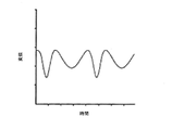
ICPモニタリングにおける別の問題は、ICPと頭蓋内容積の関係にある。図2は、ICPと頭蓋内容積の関係曲線を示している。外傷性脳損傷に係るガイドラインは、ICPを20〜25mmHg未満とするように示している(非特許文献1を参照)。しかしながら、図2に示されるように、頭蓋内容積が徐々に増しても、同図に矢印で示される臨界点までは、ICPの値はほぼ一定である。臨界点を過ぎると、ICPは急激に増加する。したがって、ICPを20mmHg未満に維持することは難しい。よって、ICPが上昇する前の脳状態を評価できる新たな方法と装置が希求されている。 Another problem with ICP monitoring is the relationship between ICP and intracranial volume. FIG. 2 shows the relationship curve between ICP and intracranial volume. Guidelines for traumatic brain injury indicate that ICP should be less than 20-25 mmHg (see Non-Patent Document 1). However, as shown in FIG. 2 , even if the intracranial volume gradually increases, the ICP value is almost constant up to the critical point indicated by the arrow in the figure. After the critical point, ICP increases sharply. Therefore, it is difficult to maintain ICP below 20 mmHg. Therefore, there is a need for new methods and devices that can evaluate the brain state before ICP rises.
CTスキャンは、患者の脳状態を評価するために広く用いられている。CT画像は、患者の頭蓋内脳「形状」を示しうる。CTは、最も有用かつ信頼性の高い外傷性脳損傷の診断法の一つである。大半の外傷性脳損傷患者は、来院時にCTスキャンの予約を受ける。また、経過観察のためのCTスキャンが必要とされることが一般的である。 CT scans are widely used to assess a patient's brain condition. CT images may show the patient's intracranial brain "shape". CT is one of the most useful and reliable diagnostic methods for traumatic brain injury. Most patients with traumatic brain injury receive a CT scan appointment at the time of their visit. Also, CT scans for follow-up are generally required.
CTスキャンの問題の一つは、CTが「連続的な」モニタでなく、普通は患者のベッドサイドで使用されないことにある。上述のように、脳卒中や頭部外傷の患者の脳組織は、発症後から徐々に膨張あるいは移動する。二次的脳損傷を避けるためにCTスキャンを頻繁に行なうこと(非特許文献2を参照)が可能だったとしても、現実的とは言えない。患者はCTスキャン室へ移動することが普通であり、ケーブル問題や感染などの患者移送に係るリスクが伴うからである。加えて、CT撮像の繰り返しは、放射線被曝やコストの増大を伴いうる(非特許文献3と4を参照)。 One of the problems with CT scans is that CT is not a "continuous" monitor and is usually not used at the patient's bedside. As mentioned above, the brain tissue of a patient with stroke or head injury gradually expands or migrates after the onset. Even if it is possible to perform frequent CT scans (see Non-Patent Document 2) to avoid secondary brain injury, it is not realistic. Patients are usually moved to a CT scan room, which involves risks associated with patient transfer such as cable problems and infections. In addition, repeated CT imaging can be associated with radiation exposure and increased costs (see Non-Patent Documents 3 and 4).
ICPは患者を管理する上で重要な変数であるが、ICPの亢進に関わる変数を理解し、積極的にモニタリングと特定の少なくとも一方を行なうことにも同様の意義がある。ICPの亢進は、例えば脳組織の膨張(浮腫)や、感染症、外傷、腫瘍、血液凝固、あるいは脳脊髄液(CSF)流の障害(水頭症)を原因とする脳内組織の拡張によって引き起こされうる。脳などの頭蓋内組織の膨張と脳室の拡張の少なくとも一方をモニタすることにより、ICPの急迫亢進だけでなくICP亢進の程度を予測するのに役立つ情報を提供でき、よって医療従事者が治療を開始するための情報、および当該治療の効果をモニタするための情報をタイムリーに提供できる。 Although ICP is an important variable in managing patients, understanding the variables involved in the enhancement of ICP and actively monitoring and at least one of them has similar significance. Increased ICP is caused by dilation of brain tissue, for example due to swelling of brain tissue (edema), infection, trauma, tumor, blood clotting, or impaired cerebrospinal fluid (CSF) flow (hydrocephalus). It can be. By monitoring at least one of the expansion of intracranial tissue such as the brain and the expansion of the ventricles, we can provide information that can help predict the extent of ICP enhancement as well as ICP urgency, thus allowing healthcare professionals to treat. Information for initiating and monitoring the effect of the treatment can be provided in a timely manner.
脳の膨張や拡大は、それを覆う約1mm厚の脳脊髄液のクッションの内側においてほぼ自由に生じる。しかしながら、脳蓋冠を満たすかアンカー点あるいはテザー点において抵抗を受けると、脳は収容空間からさらに拡張あるいは膨張し、ICPが亢進し始める。この時点、すなわち脳が頭蓋骨あるいは当該頭蓋骨におけるテザー点から抵抗を受けた時点において、膨張に起因する境界に対する脳の動きは減少する。この脳の動きの減少は、ICPが間もなく亢進することの指標として用いられうる。 Expansion and expansion of the brain occurs almost freely inside the cushion of cerebrospinal fluid about 1 mm thick that covers it. However, when the craniotomy is filled or resistance is received at the anchor or tether points, the brain further expands or expands from the containment space and ICP begins to increase. At this point, that is, when the brain receives resistance from the skull or the tether point on the skull, the movement of the brain to the boundary due to swelling is reduced. This decrease in brain movement can be used as an indicator of an upcoming increase in ICP.
本開示に係る方法の一例においては、ドプラ超音波の潜在的利用性が、特に脳卒中疑いや頭部外傷の患者(但しこれらに限定されない)における脳の膨張や移動をベッドサイドで調べるために用いられる。ドプラ超音波は、安全で可搬性のある連続的モニタリング技術であり、既に大動脈における血流のモニタリングに使用されているが、これまで脳組織の動きの分析に用いられた例はない。 In one example of the method according to the present disclosure, the potential use of Doppler ultrasound is used to examine bedside swelling and migration of the brain, especially in patients with suspected stroke or head injury, but not limited to these. Be done. Doppler ultrasound is a safe and portable continuous monitoring technique that has already been used to monitor blood flow in the aorta, but has never been used to analyze the movement of brain tissue.
集中治療や救急医療における急性脳梗塞患者の病状進行を評価およびモニタするための安価、便利、かつ有効な方法を開示する。 Disclose cheap, convenient, and effective methods for assessing and monitoring the progression of acute cerebral infarction patients in intensive care and emergency care.
出願人により提案される技術は、臨床現場で脳損傷の進行をモニタする検査ツールとして使用され、脳外傷や脳卒中後の重要な局面における治療に対応しうるものである。 The technique proposed by the applicant can be used as a test tool to monitor the progression of brain damage in the clinical setting and can be used for treatment in important aspects after brain trauma and stroke.
一仮説においては、頭蓋内血液、脳、CSF、他の要素(腫瘍や血腫など)の総体積は一定であり、頭蓋骨は密閉された非弾性容器とみなされる。頭蓋内容物のいずれかの体積の増大は、他の内容物の体積の減少とは整合していないことが一般的であり、ICPの亢進と関連付けられる。頭蓋内血液(特に静脈コンパートメント内)とCSFは、頭蓋内容物の体積増大を吸収するような適合が最も容易に可能な二つの要素である。 In one hypothesis, the total volume of intracranial blood, brain, CSF, and other elements (such as tumors and hematomas) is constant, and the skull is considered a closed inelastic container. An increase in the volume of any of the cranial contents is generally inconsistent with a decrease in the volume of the other contents and is associated with an increase in ICP. Intracranial blood (especially in the venous compartment) and CSF are the two most easily adaptable components to absorb the volume increase of the cranial contents.
本開示の一態様によれば、様々な条件下で操作者の技量や入力に依らず脳膨張により制限される正常な脳の動きと脈動の判断とモニタの少なくとも一方が行なわれうる標準化された手続を可能にする方法、キット、および装置が提供される。 According to one aspect of the present disclosure, it has been standardized that at least one of normal brain movement and pulsation determination and monitoring, which is restricted by brain swelling, can be performed under various conditions regardless of the skill and input of the operator. Methods, kits, and equipment that enable the procedure are provided.
本開示の別態様によれば、患者の頭蓋内圧の亢進を予測するキットは、超音波センサ、当該超音波センサを患者の頭部に装着するための弾性バンド、および当該超音波センサからの情報をコントローラに伝えるための通信システム(有線または無線)を含みうる。 According to another aspect of the present disclosure, a kit for predicting an increase in intracranial pressure of a patient is an ultrasonic sensor, an elastic band for attaching the ultrasonic sensor to the patient's head, and information from the ultrasonic sensor. Can include a communication system (wired or wireless) for communicating to a controller.
本開示の別態様によれば、患者の脳膨張を判断する方法は、
超音波トランスデューサを前記患者の脳に隣接するように配置すること、
第一組織部分の第二組織部分に対する位置と動きの少なくとも一方を、前記超音波トランスデューサによって受信された情報に基づいて判断すること、および
前記第一組織部分の第二組織部分に対する位置と動きの少なくとも一方の増加が目標量を上回ると判断されたとき、頭蓋内圧亢進アラームを提供すること、
を含みうる。
According to another aspect of the present disclosure, the method of determining a patient's brain swelling is
Placing the ultrasonic transducer adjacent to the patient's brain,
At least one of the position and movement of the first tissue portion with respect to the second tissue portion is determined based on the information received by the ultrasonic transducer, and the position and movement of the first tissue portion with respect to the second tissue portion. Providing an intracranial hypertension alarm when at least one increase is determined to exceed the target amount,
Can be included.
本開示の別態様によれば、患者の脳膨張を判断する方法は、前記判断に際して次式を用いて脳組織の変位を計算することを含みうる。
変位’(t)=θ’(t)λ/2/2π−θ’(t0)λ/2/2π
θ’(t)=arg[IQデータ(t)−IQ中心点]
ここで、変位’(t)は、IQデータに基づく組織変位(膨張/移動)であり、θ’(t)は、IQ中心点からのIQプロット偏角(IQ位相角)であり、IQデータ(t)は、時刻tにおけるIQデータであり、IQ中心点は、IQ軌跡の中心点である。
According to another aspect of the present disclosure, a method of determining a patient's brain swelling may include calculating the displacement of brain tissue using the following equation in the determination.
Displacement'(t) = θ'(t) λ / 2 / 2π-θ'(t0) λ / 2 / 2π
θ'(t) = arg [IQ data (t) -IQ center point]
Here, the displacement'(t) is the tissue displacement (expansion / movement) based on the IQ data, and the θ'(t) is the IQ plot deviation angle (IQ phase angle) from the IQ center point, and the IQ data. (T) is IQ data at time t, and the IQ center point is the center point of the IQ locus.
本開示の別態様によれば、患者の脳膨張を判断する装置は、
超音波トランスデューサと、
前記脳の連続的モニタリングのために、前記超音波トランスデューサを前記患者に装着するように構成された装着構造と、
前記超音波トランスデューサからの情報に基づいて脳組織の変位を計算し、前記患者の心周期と呼吸周期の少なくとも一方に起因して当該超音波トランスデューサにより検知されたデータを除去するように構成されたコントローラと、
を備えうる。
According to another aspect of the present disclosure, the device for determining a patient's brain swelling is
Ultrasonic transducer and
A mounting structure configured to mount the ultrasonic transducer on the patient for continuous monitoring of the brain.
It was configured to calculate the displacement of the brain tissue based on the information from the ultrasonic transducer and remove the data detected by the ultrasonic transducer due to at least one of the patient's cardiac cycle and respiratory cycle. With the controller
Can be equipped.
本開示の別態様によれば、患者の脳膨張を判断する装置は、次式を用いて脳組織の変位を計算するように構成されたコントローラを備えうる。
変位’(t)=θ’(t)λ/2/2π−θ’(t0)λ/2/2π
θ’(t)=arg[IQデータ(t)−IQ中心点]
ここで、変位’(t)は、IQデータに基づく組織変位(膨張/移動)であり、θ’(t)は、IQ中心点からのIQプロット偏角(IQ位相角)であり、IQデータ(t)は、時刻tにおけるIQデータであり、IQ中心点は、IQ軌跡の中心点である。
According to another aspect of the present disclosure, the device for determining a patient's brain swelling may comprise a controller configured to calculate displacement of brain tissue using the following equation.
Displacement'(t) = θ'(t) λ / 2 / 2π-θ'(t0) λ / 2 / 2π
θ'(t) = arg [IQ data (t) -IQ center point]
Here, the displacement'(t) is the tissue displacement (expansion / movement) based on the IQ data, and the θ'(t) is the IQ plot deviation angle (IQ phase angle) from the IQ center point, and the IQ data. (T) is IQ data at time t, and the IQ center point is the center point of the IQ locus.
上記の装置と方法は、脳膨張に起因する頭蓋内圧の亢進の予測に効果的である。しかしながら、当該方法は、脚や腕の筋肉におけるコンパートメント症候群などに起因する圧力の亢進の予測にも効果的である。両者は大半の点において類似している。例えば、制限された容積下に収容された組織や液体空間の膨張によって血液供給の消失(虚血)や組織の壊死が生じる点である。 The above devices and methods are effective in predicting the increase in intracranial pressure due to cerebral swelling. However, this method is also effective in predicting an increase in pressure caused by compartment syndrome in the muscles of the legs and arms. The two are similar in most respects. For example, the expansion of a tissue or liquid space housed under a restricted volume causes loss of blood supply (ischemia) or necrosis of the tissue.
上記の添付図面を参照し、装置、キット、および方法の実施形態例を示しつつ、本願の開示対象についてより詳細に説明する。 The disclosure subject of the present application will be described in more detail with reference to the above accompanying drawings, with reference to embodiments of the apparatus, kit, and method.
開示された実施形態に係る幾つかの独創的側面について、添付の図面を参照しつつ以下詳細に説明する。実施形態例は、開示対象の例示を意図して記載されたものであり、請求項により定められる範囲を限定するものではない。当業者であれば、以降の説明において提示される様々な特徴に基づいて均等の範囲に含まれる多くの改変を理解するであろう。 Some of the original aspects of the disclosed embodiments will be described in detail below with reference to the accompanying drawings. The embodiments are described with the intention of exemplifying the disclosure target, and do not limit the scope defined by the claims. One of ordinary skill in the art will understand many modifications included in the equivalent range based on the various features presented in the following description.
1.脳膨張の判断と頭蓋内圧の亢進の予測の少なくとも一方を行なうための方法および装置の例
脳頭蓋は、「半固体」の神経組織などの固体物に加えて血液と脳脊髄液を含む一定の容積を有している。唯一の大きな出口は、大後頭孔である。大後頭孔は、脳幹を収容している。脳幹は、脳室と心室を繋ぐCSFの流路を含んでいる。血管もまた頭蓋冠と外部を接続している。頭蓋内病変を評価する現在の標準手法は、頭蓋内圧(ICP)の測定を含んでいる。頭蓋内圧は、様々な時間単位で観察されうる。時間単位の例としては、秒(C波)、分(B波)、時間(A波)、日が挙げられる。これにより、起こりうる事態についての情報や治療に必要な情報が提供される。ICPは、様々な疾患において測定される。当該疾患の例としては、脳卒中、浸透圧代謝性疾患、原因不明の昏睡、水頭症、頭部外傷などが挙げられる。激しい頭痛、歩行障害、尿失禁、および認知症の評価に際してICPの測定が有用である旨が様々な文献において示されている。
1. 1. Examples of methods and devices for determining at least one of the determination of brain swelling and the prediction of increased intracranial pressure The neurocranium is a constant containing blood and cerebrospinal fluid in addition to solids such as "semi-solid" nervous tissue. It has a volume. The only large exit is the foramen magnum. The foramen magnum contains the brainstem. The brainstem contains the CSF flow path that connects the ventricles to the ventricles. Blood vessels also connect the calvaria to the outside. Current standard methods for assessing intracranial lesions include measuring intracranial pressure (ICP). Intracranial pressure can be observed in various time units. Examples of time units include seconds (C wave), minutes (B wave), hours (A wave), and days. This provides information about possible situations and information necessary for treatment. ICP is measured in various diseases. Examples of such diseases include stroke, osmotic metabolic diseases, unexplained coma, hydrocephalus, head trauma and the like. Various literatures have shown that ICP measurements are useful in assessing severe headache, gait disturbance, urinary incontinence, and dementia.
頭部外傷の場合、ICPの経時変化は、患者の転帰と関連付けられうる。例えば、ICPの亢進が二日間以内である「早期症状」を有するとみなされた場合、患者の転帰は比較的良好である。ICPが二日から五日にわたって亢進する「中間期症状」を有すると見なされた場合、患者の転帰は、早期症状の場合ほどは良くない。ICPが五日間よりも長く亢進する「後期症状」を有するとみなされた場合、患者の転帰は重篤(植物状態や死亡を含む)であることが多い。また、治療中に脳や頭蓋骨の一部が除去された場合、中間症状の割合は40%から12%に低下する一方、早期症状と後期症状の割合は、それぞれ25%から40%、35%から50%に増加する。よって、患者の転帰は、ICP症状と関連する。「早期症状」と比較すると、「後期症状」において良好な転帰は稀である。死亡、遷延性植物状態、および重度の障害は、「早期症状」の場合よりも「後期症状」の場合において多くみられる。 In the case of head trauma, changes in ICP over time can be associated with patient outcomes. For example, a patient's outcome is relatively good if ICP elevation is considered to have "early symptoms" within two days. If ICP is considered to have "intermediate symptoms" that increase over 2 to 5 days, the patient's outcome is not as good as in early symptoms. Patient outcomes are often severe (including vegetative status and death) if ICP is considered to have "late symptoms" that increase for longer than 5 days. Also, if part of the brain or skull is removed during treatment, the proportion of intermediate symptoms drops from 40% to 12%, while the proportions of early and late symptoms are 25% to 40% and 35%, respectively. Increases from to 50%. Thus, patient outcomes are associated with ICP symptoms. Good outcomes are rare in "late symptoms" when compared to "early symptoms". Death, persistent vegetative state, and severe disability are more common in "late symptoms" than in "early symptoms."
長期間の高ICPと相関する予後不良の原因は、低い脳潅流圧(CPP)、血圧(BP)とICPの差異に起因する脳組織の虚血にあると言える(CPP=BP−IP)。 It can be said that the cause of the poor prognosis that correlates with long-term high ICP is low intracranial perfusion pressure (CPP), ischemia of brain tissue due to the difference between blood pressure (BP) and ICP (CPP = BP-IP).
CPPは、経壁圧(BP−組織圧)に類似している。経壁圧は、動脈と静脈の膨張状態を維持する。経壁圧は、筋区画症候群に関連している。閉じられた筋膜区画内の浮腫によって亢進した組織圧が開存性のある静脈と動脈を圧縮する。血管壁が弛緩しているため、組織圧が管腔圧を上回ると内腔が潰れる。 CPP is similar to transwall pressure (BP-tissue pressure). Transwallal pressure maintains the inflated state of arteries and veins. Transwallal pressure is associated with compartment syndrome. Tissue pressure increased by edema within the closed fascial compartment compresses patency veins and arteries. Because the vessel wall is relaxed, the lumen collapses when the tissue pressure exceeds the lumen pressure.
CPP分析は、頭蓋内容物を圧力分布が等方的に均一な液体とみなすが、この簡略化は理解の妨げになりうる。よって、単一点におけるICP測定は、大脳と小脳全体の圧力を特徴づけるには不十分でありうる。主要な頭蓋内容物は半固体であり、複数の場所でテザリングが生じており、筋膜によって複数の区画に分割されているからである。 CPP analysis considers the cranial contents as a liquid with an isotropically uniform pressure distribution, but this simplification can be a hindrance to understanding. Thus, ICP measurements at a single point may not be sufficient to characterize pressure in the cerebrum and cerebellum as a whole. This is because the main cranial contents are semi-solid, tethering occurs at multiple locations, and is divided into multiple compartments by the fascia.
脳の一部における膨張が大きくなると、固体組織が歪み、境界が曲がることによって頭蓋内で圧力の異なる領域が生ずる。加えて、テザリングが更なる圧力変化を引き起こす。テザリングの例としては、上矢洞が挙げられる。上矢洞は、負の経壁圧を有しているが、大脳鎌のテザーによって延伸されている。固体組織において圧力が等方性(全ての方向について等しいこと)でないことは勿論である。脳の異なる領域間における圧力差は、動脈、細動脈、静脈、細静脈の圧力も領域間で異ならせる。ある領域において経壁圧が低いと、当該領域における潅流を抑制しうる一方、他の領域では潅流が促進されうる。潅流が抑制された領域は虚血状態となり、部分的な脳損傷の原因となる。右心室への静脈環流が制限されることによって呼吸に伴う動脈圧の変動が脳細静脈に反映される仰向けの患者においては、脳の一部の圧力亢進が静脈経壁圧の悪化および呼吸に伴う組織体積変化の減少の原因となる。この状態は、小静脈の「クッション効果」が失われることで動脈パルス振幅の増大の原因にもなる。局所脳圧がより深刻に亢進した患者においては、動脈経壁圧も好ましくない状態となり、脳潅流の喪失に繋がりうる。脳潅流の喪失は、細動脈組織脈動の消失によって示される。ICPが動脈圧、とりわけ収縮期脳動脈圧(90mmHg:腕血圧120mmHgから40cmのエレベーションヘモスタティック減少分30mmHgを差し引いた値)を上回ると脳パルス歪みの大きさが零に減少し、ICPが拡張期圧と収縮期圧の間の値であるときにパルス歪みが大きくなることに出願人は着目した。
Increased swelling in parts of the brain distorts solid tissue, bending boundaries and creating regions of different pressure within the skull. In addition, tethering causes further pressure changes. An example of tethering is Kamiyado. Upper Yahora has a negative transwallal pressure, but is stretched by the tether of the falx cerebri. Of course, in a solid structure the pressure is not isotropic (equal in all directions). Pressure differences between different regions of the brain also cause arterial, arteriole, vein, and venule pressure to differ between regions. Low transwall pressure in one region can suppress perfusion in that region, while facilitating perfusion in another. Areas where perfusion is suppressed become ischemic and cause partial brain damage. In patients lying on their backs, where changes in arterial pressure associated with breathing are reflected in the cerebral venules by limiting venous circulation to the right ventricle, increased pressure in part of the brain results in worsening venous transwallal pressure and breathing. It causes a decrease in the accompanying tissue volume change. This condition also causes an increase in arterial pulse amplitude due to the loss of the "cushioning effect" of the small veins. In patients with more severe local intracranial pressure, arterial transwalled pressure also becomes unfavorable, which can lead to loss of cerebral perfusion. Loss of cerebral perfusion is indicated by loss of arteriole tissue pulsation. When ICP exceeds arterial pressure, especially systolic cerebral arterial pressure (90 mmHg:
本開示に基づけば、局所潅流もモニタあるいは予測されうる。圧力は頭蓋内の区画によって異なる傾向にあるため、圧力が亢進した領域は、他の領域に比べて潅流が抑制されている可能性がある。 Local perfusion can also be monitored or predicted based on this disclosure. Since the pressure tends to vary depending on the intracranial compartment, the area of increased pressure may have less perfusion than the other areas.
加えて、分オーダーで測定されうる「遅い波」が存在する可能性がある。「遅い波」は、「充填された」圧力を解放する組織の大きな変位に起因しており、大きな脳の動きを引き起こす点において「地震」に類似している。この種の「地震」型イベントの影響を軽減し、あるいはデータを無効化から保護するために、開示内容に係るソフトウェアとハードウェアの少なくとも一方に特定のノイズフィルタが内蔵されうる。 In addition, there may be "slow waves" that can be measured on the order of minutes. "Slow waves" are similar to "earthquakes" in that they result in large displacements of tissue that release "filled" pressure and cause large brain movements. Certain noise filters may be built into at least one of the disclosed software and hardware to mitigate the effects of this type of "earthquake" event or to protect the data from invalidation.
病的状態においては、ICPは様々な仕組みによって亢進する。仕組みの例としては、1)水頭症の原因となる脳脊髄液(CSF)の流出異常、2)固体組織の膨張が挙げられる。固体組織の膨張には、2a)脳浮腫、2b)頭蓋内血腫、および2c)腫瘍が含まれる。 In pathological conditions, ICP is enhanced by various mechanisms. Examples of the mechanism include 1) abnormal outflow of cerebrospinal fluid (CSF) that causes hydrocephalus, and 2) swelling of solid tissue. Solid tissue swelling includes 2a) cerebral edema, 2b) intracranial hematoma, and 2c) tumor.
幾つかのICPのインヴィボモデルにおいては、脳や脊髄に液体を注入することによって「脳弾性」(dP/dV)が測定されている。当該モデルは、脳組織が圧縮可能であること、あるいは頭蓋内の血管と液体の境界は弾性を有していることを前提としている。出願人は、頭蓋/脳力学における代替概念を検討した。 In some ICP invivo models, "brain elasticity" (dP / dV) is measured by injecting fluid into the brain or spinal cord. The model assumes that the brain tissue is compressible or that the intracranial blood vessel-fluid boundary is elastic. Applicants examined alternative concepts in cranial / brain mechanics.
出願人の研究は、脳卒中が疑われる患者あるいは頭部を損傷した患者の脳膨張や脳移動をベッドサイドで評価するためにドプラ超音波を使用する可能性を見出した。ドプラ超音波は、安全で可搬性のある連続的モニタリング技術である。ドプラ超音波は、既に大動脈における血流のモニタリングに使用されているが、これまで脳組織の動きの分析に用いられた例はない。 The applicant's study found the possibility of using Doppler ultrasound to assess bedside swelling and cerebral migration in patients with suspected stroke or head injuries. Doppler ultrasound is a safe and portable continuous monitoring technology. Doppler ultrasound has already been used to monitor blood flow in the aorta, but has never been used to analyze the movement of brain tissue.
集中治療や救急医療における急性脳梗塞患者の病状進行を評価およびモニタするための安価、便利、かつ有効な方法を開示する。 Disclose cheap, convenient, and effective methods for assessing and monitoring the progression of acute cerebral infarction patients in intensive care and emergency care.
出願人により提案される技術は、臨床現場で脳損傷の進行をモニタする検査ツールとして使用され、脳外傷や脳卒中後の重要な局面における治療に対応しうるものである。 The technique proposed by the applicant can be used as a test tool to monitor the progression of brain damage in the clinical setting and can be used for treatment in important aspects after brain trauma and stroke.
本開示の一実施形態によれば、システムと測定アルゴリズムが用いられうる。図3と図4に示されるように、検査システムは、患者の脳をモニタする方法を遂行するために使用されうる。具体的には、経頭蓋ドプラ(スペンサー社のT3など)が使用されうる。弾性バンドを用いて超音波プローブを側頭骨窓または額に装着することにより、コントローラを介して脳組織の膨張や移動を測定する。 According to one embodiment of the present disclosure, a system and a measurement algorithm may be used. As shown in FIGS. 3 and 4, testing systems can be used to carry out methods of monitoring a patient's brain. Specifically, transcranial Doppler (such as Spencer's T3) can be used. By attaching an ultrasonic probe to the temporal bone window or forehead using an elastic band, expansion and movement of brain tissue are measured via a controller.

各深度における時刻0からtまでの脳組織の膨張または移動(変位)は、次式を用いて計算されうる。
変位(t)=θ(t)λ/2/2π−θ(t0)λ/2/2π (1)
λ=1000c/f (2)
ここで、tは時間であり、変位(ゲート、t)は、組織変位(膨張または移動)[μm]であり、θ(t)は、IQプロット偏角(IQ位相角)であり、λは、超音波の波長[μm]であり、cは、超音波の速度(1.54[mm/μs])であり、fは、超音波の周波数(2[MHz])である。
The expansion or movement (displacement) of brain tissue from
Displacement (t) = θ (t) λ / 2 / 2π−θ (t0) λ / 2 / 2π (1)
λ = 1000c / f (2)
Here, t is time, displacement (gate, t) is tissue displacement (expansion or movement) [μm], θ (t) is IQ plot deviation (IQ phase angle), and λ is. , C is the wavelength of the ultrasonic wave [μm], c is the velocity of the ultrasonic wave (1.54 [mm / μs]), and f is the frequency of the ultrasonic wave (2 [MHz]).
位相角θ(t)は、各IQデータから計算される。変位は、位相角θ(t)と波長(λ/2)を乗ずることによって計算される。IQデータの軌跡は、図6Aに示されるように、IQ平面の原点(0,0)を中心とする弧を描く。式(1)により計算される組織の変位は、図6Bに示される。 The phase angle θ (t) is calculated from each IQ data. The displacement is calculated by multiplying the phase angle θ (t) by the wavelength (λ / 2). The locus of IQ data draws an arc centered on the origin (0,0) of the IQ plane, as shown in FIG. 6A. The displacement of the tissue calculated by equation (1) is shown in FIG. 6B.
この手法においては、時刻0からtまでの脳組織変位が測定されるが、特定の時刻における脳組織の絶対位置は提供されない。しかしながら、「連続的な」測定あるいはモニタリングにより、この手法でも測定開始(時刻0)から現在までの総変位を提供できる。これにより、モニタリング中に生じた移動あるいは膨張が検出される。
In this technique, the displacement of the brain tissue from
図6Aと図6Bに示されるように、IQデータの中心点は、基本的にIQ平面の原点(0,0)に位置する。しかしながら、IQデータは、骨反射に起因する定常的な反響雑音信号などを含むことが多い。この場合、中心点が原点からシフトする。 As shown in FIGS. 6A and 6B, the center point of the IQ data is basically located at the origin (0,0) of the IQ plane. However, IQ data often includes stationary reverberant noise signals due to bone reflexes and the like. In this case, the center point shifts from the origin.
図7Aと図7Bは、組織変位信号と定常的な反響雑音信号を含むIQデータのシミュレーション例を示している。組織変位信号としては、正弦波が用いられうる。図7Aに示されるように、IQ軌跡の中心点は、原点からシフトしている。図7Bに示されるように、式(1)により計算される組織変位信号は、正弦波ではない。したがって、IQデータは、中心点を原点からシフトさせる定常的な反響雑音信号などを含む。この場合、式(1)では組織変位を正確に計算できない。 7A and 7B show an example of a simulation of IQ data including a tissue displacement signal and a stationary echo noise signal. A sine wave may be used as the tissue displacement signal. As shown in FIG. 7A, the center point of the IQ locus is shifted from the origin. As shown in FIG. 7B, the tissue displacement signal calculated by Eq. (1) is not a sine wave. Therefore, the IQ data includes a stationary reverberant noise signal that shifts the center point from the origin. In this case, the tissue displacement cannot be calculated accurately by the equation (1).
補正組織変位を計算するために、中心点を原点からシフトさせる定常的な反響雑音信号などが除去されうる。当該データが除去されると、IQ位相角(IQプロット偏角)は、座標(0,0)からではなくIQ軌跡の中心点から測定される。IQ軌跡の中心点は、心周期ごとに、あるいは数秒ごとに計算される。図8のフローチャートに示されるように、IQ位相角(偏角)は、IQ軌跡の中心点から計算される。 In order to calculate the corrected tissue displacement, a stationary reverberant noise signal that shifts the center point from the origin can be removed. When the data is removed, the IQ phase angle (IQ plot declination) is measured from the center point of the IQ locus rather than from the coordinates (0,0). The center point of the IQ locus is calculated every cardiac cycle or every few seconds. As shown in the flowchart of FIG. 8, the IQ phase angle (argument) is calculated from the center point of the IQ locus.
この場合、時刻0からtまでの正しい脳組織変位は、次式を用いて計算される。
変位’(t)=θ’(t)λ/2/2π−θ’(t0)λ/2/2π (3)
θ’(t)=arg[IQデータ(t)−IQ中心点] (4)
ここで、変位’(t)は、IQデータに基づく組織変位(膨張/移動)[μm]であり、θ’(t)は、IQ中心点からのIQプロット偏角(IQ位相角)であり、IQデータ(t)は、時刻tにおけるIQデータであり、IQ中心点は、IQ軌跡の中心点である。
In this case, the correct brain tissue displacement from
Displacement'(t) = θ'(t) λ / 2 / 2π-θ'(t0) λ / 2 / 2π (3)
θ'(t) = arg [IQ data (t) -IQ center point] (4)
Here, the displacement'(t) is the tissue displacement (expansion / movement) [μm] based on the IQ data, and the θ'(t) is the IQ plot deviation angle (IQ phase angle) from the IQ center point. , IQ data (t) is IQ data at time t, and the IQ center point is the center point of the IQ locus.
図9Aは、非補正変位を示している。図9Bは、上式(3)によって計算された補正変位を示しており、正弦波を描いている。当該正弦波は、組織変位信号を再現するシミュレーションに使用されるものである。すなわち、ここに開示されるアルゴリズムは、定常的な反響雑音信号を除去可能なものである。 FIG. 9A shows the uncorrected displacement. FIG. 9B shows the corrected displacement calculated by the above equation (3) and draws a sine wave. The sine wave is used in a simulation that reproduces a tissue displacement signal. That is, the algorithm disclosed herein is capable of removing stationary reverberant noise signals.
心周期や呼吸周期に由来する脳の動きは、脳位置を計算するための上記アルゴリズムを用いて除去可能であり、本開示に係る装置と方法により実際の膨張が明瞭に認識可能である。さらに、心周期、血圧変化、および並行する呼吸の少なくとも一つに起因する脳組織の周期的変位は、本開示に係る測定方法により除去されうる。本開示に係る装置と方法は、ドプラ式超音波センサとコントローラの使用を通じて、正確な脳の位置と動きデータを提供できる。 The movement of the brain derived from the cardiac cycle and respiratory cycle can be removed by using the above algorithm for calculating the brain position, and the actual expansion can be clearly recognized by the apparatus and method according to the present disclosure. In addition, periodic displacement of brain tissue due to at least one of the cardiac cycle, blood pressure changes, and parallel respiration can be eliminated by the measurement methods according to the present disclosure. The devices and methods according to the present disclosure can provide accurate brain position and motion data through the use of Doppler ultrasonic sensors and controllers.
British Medical Ultrasound Societyにより刊行された経頭蓋ドプラモニタリングのための安全ガイドライン(BMUS 2009)が規範とされることが多い。当該文献は、以下のように示している。 Safety guidelines for transcranial Doppler monitoring (BMUS 2009) published by the British Medical Ultrasound Society are often the norm. The document shows as follows.
したがって、TIC<1.0の条件を維持するために電力(TCDシステム電力)の40%を使用して測定値の記録を行なうことにした。 Therefore, in order to maintain the condition of TIC <1.0, it was decided to record the measured value using 40% of the electric power (TCD system electric power).
健康な協力者によるテスト
仮説を立証するために、以下のテストを行なった。
・ヴァルサルヴァ法テスト
・仰臥位(−20度)テスト
Tests by Healthy Collaborators To substantiate the hypothesis, the following tests were performed.
・ Valsalva maneuver test ・ Supine position (-20 degrees) test
ヴァルサルヴァ法
ヴァルサルヴァ法は、通常は患者の口を閉じて鼻をつまむことによって気道を閉じた状態で、風船を膨らませるかのように、やや強制的に息を吐こうとすることによって行なわれる。
Valsalva Maneuver The Valsalva maneuver is usually performed by closing the patient's mouth and pinching his nose to close the airway and trying to exhale slightly forcibly, as if inflating a balloon. Is done.
ヴァルサルヴァ法テスト中は、胸腔内圧が上昇し、中心静脈圧も上昇する。したがって、通常は脳内の静脈血量が増加し、結果として脳が膨張する(ICPも亢進する)。よって、本出願人は、頭に装着された超音波トランスデューサを用いて、ヴァルサルヴァ法テスト中に脳膨張が測定できると考えた。 During the Valsalva maneuver test, intrathoracic pressure increases and central venous pressure also increases. Therefore, the amount of venous blood in the brain usually increases, resulting in swelling of the brain (also increases ICP). Therefore, Applicants believed that brain swelling could be measured during the Valsalva maneuver test using an ultrasonic transducer worn on the head.
ヴァルサルヴァ法テストの手順は以下の通りである。
プローブ位置:側頭窓
手順:約10秒の安静 → 約30秒のヴァルサルヴァ法 → 約30秒の安静
The procedure for the Valsalva maneuver test is as follows.
Probe position: Infratemporal window Procedure: Rest for about 10 seconds → Valsalva maneuver for about 30 seconds → Rest for about 30 seconds
仰臥位(−20度)テスト
仰臥位の間、頭蓋内静脈血量は増加し、脳組織が膨張する。本出願人は、頭に装着された超音波センサを用いて、患者が仰臥位でいる間に脳膨張が測定できると考えた。
Supine position (-20 degrees) test During the supine position, intracranial venous blood volume increases and brain tissue swells. Applicants believed that an ultrasonic sensor worn on the head could be used to measure brain swelling while the patient was in the supine position.
仰臥位(−20度)テストの手順は以下の通りである。
プローブ位置:側頭窓
手順:約20秒の座位 → 約60秒の仰臥位(−20度) → 約40秒の座位
The procedure for the supine position (-20 degrees) test is as follows.
Probe position: Infratemporal window Procedure: Sitting position for about 20 seconds → Supine position for about 60 seconds (-20 degrees) → Sitting position for about 40 seconds
結果
ヴァルサルヴァ法
図10から図12は、ヴァルサルヴァ法が行なわれている間の脳組織データを示している。頭表面からの測定深度は、それぞれ25mm、50mm、および75mmである。
Results Figure 12 Varusaruva method Figure 10 shows a brain tissue data between the Varusaruva method is performed. The measurement depths from the head surface are 25 mm, 50 mm, and 75 mm, respectively.
図10から図12に示されるように、超音波システムは脳組織変位を測定可能であると言え、これを「脳膨張測定」と称する。深度25mmの測定において、脳組織の膨張は約1.0mmであった。深度50mmの測定において、脳組織の膨張は約2.5mmであった。深度75mmの測定において、脳組織の膨張は約3.5mmであった。すなわち、深くにある脳組織ほど膨張が大きかった。本出願人は、その理由を、脳組織が堅い頭蓋骨に収容された「スポンジ」状のものであるからと考えた。 As shown in FIGS. 10 to 12, it can be said that the ultrasonic system can measure the displacement of brain tissue, which is referred to as "brain expansion measurement". At a depth of 25 mm, the swelling of the brain tissue was about 1.0 mm. At a depth of 50 mm, the swelling of the brain tissue was about 2.5 mm. At a depth of 75 mm, the swelling of the brain tissue was about 3.5 mm. That is, the deeper the brain tissue, the greater the swelling. Applicants attributed this to the "sponge" -like brain tissue contained in a rigid skull.
仰臥位(−20度)
図13から図15は、仰臥位である間の脳組織データを示している。頭表面からの測定深度は、それぞれ25mm、50mm、および75mmである。
Supine position (-20 degrees)
13 to 15 show brain tissue data while in the supine position. The measurement depths from the head surface are 25 mm, 50 mm, and 75 mm, respectively.
図13から図15に示されるように、脳組織変位は、超音波システムを用いて仰臥位テスト中にも測定可能と言える。深度25mmの測定において、脳組織の膨張は約0.5mmであった。深度50mmの測定において、脳組織の膨張は約0.75mmであった。深度75mmの測定において、脳組織の膨張は約1.5mmであった。ヴァルサルヴァ法テストの場合と同様に、深くにある脳組織ほど膨張が大きかった。 As shown in FIGS. 13 to 15, it can be said that the brain tissue displacement can be measured even during the supine position test using an ultrasonic system. At a depth of 25 mm, the swelling of the brain tissue was about 0.5 mm. At a depth of 50 mm, the swelling of the brain tissue was about 0.75 mm. At a depth of 75 mm, the swelling of the brain tissue was about 1.5 mm. As in the Valsalva maneuver test, the deeper the brain tissue, the greater the swelling.
脳膨張は、超音波を用いて測定されうる。この脳膨張/移動モニタは、二次的脳損傷を回避するための新たなツールとなりうる。図3に示されるように患者に接続された心電計電極に似た超音波トランスデューサは、連続的な測定とモニタリングを容易にし、脳膨張の測定を助ける。本開示に係る膨張モニタは、新たな患者モニタパラメータとして使用されうる。本開示に係る膨張モニタとその使用法によれば、膨張/移動だけでなく膨張の進み具合も測定できる。 Brain swelling can be measured using ultrasound. This brain expansion / movement monitor can be a new tool for avoiding secondary brain injury. An ultrasonic transducer similar to an electrocardiograph electrode connected to a patient as shown in FIG. 3 facilitates continuous measurement and monitoring and aids in the measurement of brain swelling. The expansion monitor according to the present disclosure can be used as a new patient monitor parameter. According to the expansion monitor and its usage according to the present disclosure, not only the expansion / movement but also the progress of expansion can be measured.
膨張モニタとその使用法における特徴は、超音波を用いた脳膨張/移動の測定、患者のベッドサイドにおける連続的な測定、および「相対的な」脳組織変位の測定にある。よって、本開示に係る装置と方法の一実施形態においては、測定は連続的に行なわれ、断続的には行なわれない。 A feature of the expansion monitor and its usage is the measurement of brain expansion / movement using ultrasound, the continuous measurement at the patient's bedside, and the measurement of "relative" brain tissue displacement. Therefore, in one embodiment of the apparatus and method according to the present disclosure, measurements are made continuously, not intermittently.
なお、超音波トランスデューサは、コントローラと「通信可能に接続」されうる。当該接続は、有線接続(金属線、光ファイバなどの物理的接続)によりなされてもよいし、無線接続(wi−fi、ブルートゥース技術などの無線接続あるいは無線通信プロトコル)によりなされてもよい。稼働時において、コントローラは、一般的な超音波デバイスに内蔵されてもよいし、別体として設置されてもよい。コントローラは、第一脳組織部分の第二脳組織部分に対する位置の取得、判断、およびモニタの少なくとも一つを行なうように構成されたソフトウェアとハードウェアの少なくとも一方を備える。当該ソフトウェアとハードウェアの少なくとも一方は、第一目標組織の位置情報が取得され、続いて第二目標組織に対する位置情報と比較されるように構成されうる。当該情報が心周期に対応して予期される経時的脈動を示す場合、コントローラは、脳が正常に膨張できると判断する。当該情報が呼吸に伴う周期的膨張を示す場合、コントローラは、脳内の静脈圧が頭蓋内圧を上回っている(仰臥位の患者については正常)と判断する。当該情報が、加速度計によりモニタされる頭蓋骨の位置と向きの少なくとも一方に合致した位置の経時変化を示す場合、コントローラは、脳が正常にCSF内に浮いていると判断する。当該情報が変化の経時的進行を示す場合、コントローラは、脳が膨張していると判断する。当該情報が経時的変化の減少を示す場合、あるいは運動期間後に相対移動の不在を示す場合、コントローラは、脳が膨張しており、かつICPが間もなく亢進すると判断する。ICPが亢進するとコントローラが判断すると、モニタやリモートアラームを介して医療従事者へ情報が提供されうる。これにより、医療従事者は、患者のICPが亢進しそうであることを知らされる。モニタ装置は、コントローラに内蔵されてもよいし、有線接続または無線接続を介してコントローラに接続されてもよい。同様に、アラーム装置も有線接続または無線接続を介してコントローラに接続されうる。あるいは、アラーム装置は、携帯電話などの遠隔通信装置でありうる。コントローラは、サーバに情報を提供するように構成されうる。その場合、当該サーバは、当該情報を管理し、様々な受信装置(携帯電話、タブレット、コンピュータなどの形態をとるアラーム装置など)と通信を行なう。当該情報を最適管理し、特定の遠隔装置へ提供するための様々なアプリケーションも開発されうる。 It should be noted that the ultrasonic transducer can be "communicably connected" to the controller. The connection may be made by a wired connection (a physical connection such as a metal wire or an optical fiber) or by a wireless connection (a wireless connection such as wi-fi or Bluetooth technology or a wireless communication protocol). At the time of operation, the controller may be built in a general ultrasonic device or may be installed as a separate body. The controller comprises at least one of software and hardware configured to perform at least one of the acquisition, determination, and monitoring of the position of the first brain tissue portion with respect to the second brain tissue portion. At least one of the software and hardware may be configured to obtain location information for the first target organization and then compare it to location information for the second target organization. If the information indicates the expected pulsation over time corresponding to the cardiac cycle, the controller determines that the brain can swell normally. If the information indicates respiratory periodic swelling, the controller determines that the venous pressure in the brain is above the intracranial pressure (normal for patients in the supine position). If the information indicates a change over time in a position that matches at least one of the position and orientation of the skull monitored by the accelerometer, the controller determines that the brain is normally floating in the CSF. If the information indicates the progress of change over time, the controller determines that the brain is inflated. If the information indicates a decrease in change over time, or the absence of relative movement after a period of exercise, the controller determines that the brain is inflated and the ICP is about to increase. If the controller determines that ICP is enhanced, information may be provided to the healthcare professional via a monitor or remote alarm. This informs the healthcare professional that the patient's ICP is likely to increase. The monitoring device may be built into the controller or may be connected to the controller via a wired or wireless connection. Similarly, the alarm device may be connected to the controller via a wired or wireless connection. Alternatively, the alarm device can be a remote communication device such as a mobile phone. The controller may be configured to provide information to the server. In that case, the server manages the information and communicates with various receiving devices (alarm devices in the form of mobile phones, tablets, computers, etc.). Various applications can be developed to optimally manage the information and provide it to a specific remote device.
なお、本開示においては、超音波などのトランスデューサから所望の解像度を得るために無線位相変調が使用されうる。例えば、脳組織内の0.1ミクロンの変位が測定できるように解像度が設定されうる。 In this disclosure, radio phase modulation can be used to obtain the desired resolution from a transducer such as an ultrasonic wave. For example, the resolution can be set so that a displacement of 0.1 micron within the brain tissue can be measured.
コントローラは、脳組織の自身に対する位置関係のより正確な判断(すなわち、脳膨張などを判断するための、第一目標脳組織の第二目標脳組織に対する位置変化量の判断)を提供するために、他のセンサにも接続されうる。例えば、加速度計が患者の頭部と胸部(胸骨上)の少なくとも一方に装着されうる。これにより、これら二つの身体領域の位置と動きがモニタされる。当該動きは、二つの目標脳組織間の位置関係や目標脳組織と右心房の間のエレベーション(圧力の基準に使用されうる)をより正確に計算するために使用されうる。より具体的には、頭蓋骨と胸骨上に配置された加速度計が、右心房と測定対象の身体部位(頭蓋骨や脳など)との間の相対高度差を判断するために使用されうる。加えて、呼吸センサと肺センサの少なくとも一方がコントローラと接続されうる。これにより、呼吸機能と肺機能の少なくとも一方に係る情報が、二つの目標脳組織の間の位置関係をより正確に計算するために、そして膨張の存在をより正確に判断するために使用されうる。一例として、呼吸センサと肺センサの少なくとも一方は、加速度計と心電図センサのいずれかと組み合わせられうる。近年、絆創膏のようにユーザの頭部に装着し、特にスポーツ時における頭部の加速度をリアルタイムにモニタするために加速度データを無線送信する超小型回路パッチが利用可能になっている。加速度計は、そのような超小型回路を同様に備えるように構成可能と考えられる。加えて、脳組織の膨張は比較的小さい一方で患者の解剖学的ジオメトリの間には大きなばらつきがあるので、膨張と位置の測定および計算の精度を確実に高めるために、ベースラインデータの使用が助けになる。例えば、アスリートについて、頭蓋骨と脳の位置データを含むベースラインデータが収集されることがある。この種のベースライン情報は、ベースライン情報を入手可能な特定の患者への本開示に係るシステム/装置の使用中において、精度を上げるために利用されうる。 The controller provides a more accurate determination of the positional relationship of the brain tissue with respect to itself (that is, determination of the amount of change in the position of the first target brain tissue with respect to the second target brain tissue for determining brain swelling, etc.). , Can be connected to other sensors. For example, an accelerometer can be worn on at least one of the patient's head and chest (above the sternum). This monitors the position and movement of these two body areas. The movement can be used to more accurately calculate the positional relationship between the two target brain tissues and the elevation between the target brain tissue and the right atrium (which can be used as a measure of pressure). More specifically, an accelerometer located on the skull and sternum can be used to determine the relative altitude difference between the right atrium and the body part to be measured (such as the skull or brain). In addition, at least one of the respiratory and lung sensors may be connected to the controller. This allows information on at least one of respiratory and lung function to be used to more accurately calculate the positional relationship between the two target brain tissues and to more accurately determine the presence of swelling. .. As an example, at least one of the respiratory and lung sensors can be combined with either an accelerometer or an electrocardiogram sensor. In recent years, ultra-small circuit patches that are worn on the user's head like adhesive plasters and wirelessly transmit acceleration data to monitor the acceleration of the head in real time, especially during sports, have become available. Accelerometers could be configured to include such microcircuits as well. In addition, while the swelling of brain tissue is relatively small, there is large variability between the patient's anatomical geometry, so the use of baseline data to ensure the accuracy of swelling and position measurements and calculations. Helps. For example, for athletes, baseline data may be collected, including skull and brain location data. Baseline information of this kind, during use of the system / equipment according baseline information on the present disclosure to a particular patient available, can be utilized to improve the accuracy.
脳組織を含む頭蓋内組織は、自然な脈動を呈する。普通に直立した人の場合、心臓に起因する動きは約20μmであり、約20μmである呼吸に起因する動きと重なっている。当該動きは、一般にプレスシモグラフィ法によって検出される重複波を伴う。重複波の存在は相対的な血管収縮を示し、当該波の消失は相対的な血管拡張を示す。直立した人の呼吸に起因する動きは、心臓に対する頭部の高さ(圧)よりも中心静脈圧が低いので、呼吸による心拍出量の変化に依存する傾向にある。人が仰向けになると、心拍出量成分とは位相が異なる別の呼吸成分が加わりうる。動きは両側性となり、脳室が拡張する。 Intracranial tissue, including brain tissue, exhibits natural pulsations. In the case of a normally upright person, the movement caused by the heart is about 20 μm, which overlaps with the movement caused by breathing, which is about 20 μm. The movement is accompanied by overlapping waves commonly detected by the press simography method. The presence of overlapping waves indicates relative vasoconstriction and the disappearance of the waves indicates relative vasodilation. The movements caused by the breathing of an upright person tend to depend on the change in cardiac output due to breathing because the central venous pressure is lower than the height (pressure) of the head with respect to the heart. When a person lies on his back, another respiratory component that is out of phase with the cardiac output component may be added. The movement is bilateral and the ventricles dilate.
脳(および他の頭蓋内組織)は、心周期と呼吸周期の双方に基づいて伸縮する。しかしながら、脳の体積は、頭蓋骨(および上述した他のテザー点)によって制約を受ける。脳などの頭蓋内組織の拡張または膨張は、脳内における脳室を圧迫する。脳は、心周期ごとに内側、後側、および尾側へ動かされる。これらの動きは、頭蓋内組織膨張(多くの場合において頭蓋内圧の亢進に起因)を判断するために提案されたモニタリングシステムに基づく。 The brain (and other intracranial tissue) expands and contracts based on both the cardiac and respiratory cycles. However, the volume of the brain is constrained by the skull (and other tether points mentioned above). Expansion or swelling of intracranial tissue such as the brain compresses the ventricles in the brain. The brain is moved medially, posteriorly, and caudally during each cardiac cycle. These movements are based on a monitoring system proposed to determine intracranial tissue swelling (often due to increased intracranial pressure).
図16は、本開示に係る別実施形態を模式的に示す図である。本実施形態においては、脳組織の膨張/移動モニタは、超音波プローブまたはトランスデューサを介して患者などのユーザに接続される。超音波プローブは、フレキシブルバンドにより特定の目標領域を向くようにして患者の頭部に装着されうる。超音波プローブに接続された超音波コントローラは、高電圧パルスのバーストをプローブに送信する。これにより、プローブが超音波を発する。そしてプローブは、患者の脳組織(および脳を包囲する他の組織)に反射された超音波信号(RF信号)を受信する。コントローラは、超音波RF信号に基づいて生成されたIQデータから脳組織の変位量を計算する。組織変位データは、記録/モニタ装置(患者モニタ、コンピュータ、データ制御装置、データ記憶装置、ネットワークシステムなど)へ送信されうる。コントローラは、患者モニタなどのデータレコーダに内蔵されてもよいし、有線接続または無線接続されてもよい。例えば、コントローラは、中央監視システムに関連付けられたモニタ装置(米国特許第8638192号明細書などに記載)やベッドサイドモニタ装置(米国特許第9049993号明細書などに記載)に内蔵されうる。 FIG. 16 is a diagram schematically showing another embodiment according to the present disclosure. In this embodiment, the brain tissue expansion / movement monitor is connected to a user such as a patient via an ultrasonic probe or transducer. The ultrasonic probe can be worn on the patient's head with a flexible band facing a specific target area. The ultrasonic controller connected to the ultrasonic probe sends a burst of high voltage pulses to the probe. This causes the probe to emit ultrasonic waves. The probe then receives an ultrasonic signal (RF signal) reflected by the patient's brain tissue (and other tissue surrounding the brain). The controller calculates the displacement of the brain tissue from the IQ data generated based on the ultrasonic RF signal. Tissue displacement data can be transmitted to recording / monitoring devices (patient monitors, computers, data controls, data storage devices, network systems, etc.). The controller may be built into a data recorder such as a patient monitor, or may be wired or wirelessly connected. For example, the controller may be built into a monitoring device associated with a central monitoring system (described in US Pat. No. 8,638,192, etc.) or a bedside monitoring device (described in US Pat. No. 9094993, etc.).
図17Aと図17Bは、それぞれ本開示の原理に基づいて構成された超音波コントローラの別実施形態を模式的に示すブロック図と写真である。超音波コントローラは、少なくともフィールドプログラマブルゲートアレイ(FPGA)、高電圧源、送信器、T/Rスイッチ、低ノイズ増幅器(LNA)、プログラマブルゲイン増幅器(PGA)、差動増幅器、バンドパスフィルタ(BPF)、A/D変換器(ADC)、プローブコネクタ、通信インターフェースコネクタなどの部品を備えうる。図17Aに示されるように、超音波プローブは、BNCコネクタに接続されうる。送信器は、約2MHzの高電圧バーストパルス(±4V〜25V)を生成しうる。T/Rスイッチは、送信される高電圧バーストパルス信号を除去し、脳などの組織からの反射超音波信号を抽出しうる。増幅器(LNA、PGA、および差動増幅器)は、信号電圧を増大させる(−4dB〜+36dB)ために設けられうる。ADCは、信号をデジタル化する。本図において、IQ復調は、FPGAによって遂行される(デジタルIQ復調)。RFデータまたはIQデータは、USBワイヤなどの通信ケーブルまたは無線通信を介して患者モニタ(図16)に送信される。 17A and 17B are block diagrams and photographs schematically showing another embodiment of the ultrasonic controller configured based on the principle of the present disclosure, respectively. The ultrasonic controller is at least a field programmable gate array (FPGA), high voltage source, transmitter, T / R switch, low noise amplifier (LNA), programmable gain amplifier (PGA), differential amplifier, bandpass filter (BPF). , A / D converter (ADC), probe connector, communication interface connector and the like. As shown in FIG. 17A, the ultrasonic probe may be connected to a BNC connector. The transmitter can generate a high voltage burst pulse (± 4V to 25V) of about 2MHz. The T / R switch can remove the transmitted high voltage burst pulse signal and extract the reflected ultrasonic signal from tissues such as the brain. Amplifiers (LNA, PGA, and differential amplifiers) can be provided to increase the signal voltage (-4 dB to +36 dB). The ADC digitizes the signal. In this figure, IQ demodulation is performed by FPGA (digital IQ demodulation). The RF data or IQ data is transmitted to the patient monitor (FIG. 16) via a communication cable such as a USB wire or wireless communication.
図18Aと図18Bは、それぞれ本開示の原理に基づいて構成された超音波プローブの別実施形態を模式的に示すブロック図と写真である。超音波プローブは、少なくとも圧電素子、バッキング材、音響整合層、および筐体を備えうる。 18A and 18B are block diagrams and photographs schematically showing another embodiment of the ultrasonic probe configured based on the principles of the present disclosure, respectively. The ultrasonic probe may include at least a piezoelectric element, a backing material, an acoustic matching layer, and a housing.
使用時は、超音波コントローラ(図16)の送信器によって高電圧バーストパルスが生成され、超音波プローブの圧電素子に印加される。圧電素子は、伸縮を繰り返すことによって振動し、超音波を生成する。目標組織から反射された振動(または超音波)を受けると、圧電素子は、目標素子の像に相関する電圧を生成する。 During use, the transmitter of the ultrasonic controller (FIG. 16) generates a high voltage burst pulse that is applied to the piezoelectric element of the ultrasonic probe. The piezoelectric element vibrates by repeating expansion and contraction, and generates ultrasonic waves. Upon receiving vibrations (or ultrasonic waves) reflected from the target tissue, the piezoelectric element produces a voltage that correlates with the image of the target element.
バッキング材は、圧電素子の背後に配置されて過剰な振動を防止するとともに、圧電素子によって出力される振動特性を制御するように構成されている。バッキング材の形状と材料は、圧電素子によって生成される超音波のパルス長を短縮するように選択されうる。 The backing material is arranged behind the piezoelectric element to prevent excessive vibration and is configured to control the vibration characteristics output by the piezoelectric element. The shape and material of the backing material can be selected to reduce the pulse length of the ultrasonic waves generated by the piezoelectric element.
圧電素子から送出された超音波は、目標組織を含む隣接組織に反射することによって、当該目標組織への到達と通過の少なくとも一方が阻止される。圧電素子と隣接組織または物体との間で音響インピーダンスが相違するからである。この現象を避けるために、そして目標組織まで(あるいはその内部まで)超音波が深く進入することを確実にするために、圧電素子と目標組織の間に中間材(音響整合層)が介挿されうる。これにより、超音波は、目標物と目標組織の少なくとも一方へ効率的に進入できる。圧電素子に隣接する音響レンズを設けてもよい。音響レンズは、生成された超音波ビームを目標組織へ向けて収束するように構成されうる。 The ultrasonic waves transmitted from the piezoelectric element are reflected by the adjacent tissue including the target tissue, so that at least one of reaching and passing through the target tissue is blocked. This is because the acoustic impedance differs between the piezoelectric element and the adjacent tissue or object. An intermediate material (acoustic matching layer) is inserted between the piezoelectric element and the target structure to avoid this phenomenon and to ensure that the ultrasonic waves penetrate deeply into (or even inside) the target structure. sell. This allows the ultrasound to efficiently enter at least one of the target and the target tissue. An acoustic lens adjacent to the piezoelectric element may be provided. The acoustic lens may be configured to converge the generated ultrasonic beam towards the target tissue.
実施形態の例を参照しつつ開示の対象について詳細に説明してきたが、発明の趣旨を逸脱しなければ様々な変更がなされうること、および等価物が採用されうることは、当業者にとって明らかである。特に、発明の趣旨を逸脱しなければ、開示された特定の実施形態の各々に係る特徴は、開示された他の実施形態の各々との入替えや組合せがなされうる。背景技術の説明において参照した関連文献の全ては、本開示の一部を構成するものとして援用される。 Although the subject of disclosure has been described in detail with reference to the examples of the embodiments, it is clear to those skilled in the art that various changes can be made and equivalents can be adopted without departing from the spirit of the invention. be. In particular, without departing from the spirit of the invention, the features of each of the disclosed specific embodiments may be replaced or combined with each of the other disclosed embodiments. All of the relevant literature referred to in the description of the background art is incorporated as part of this disclosure.
Claims (7)
超音波トランスデューサを前記患者の脳に隣接する頭部に装着する装着構造と、
前記患者の第一脳組織部分の第二脳組織部分に対する位置を示す情報を、前記超音波トランスデューサを通じて取得し、当該情報の経時変化に基づいて前記患者の頭蓋内圧が亢進するかを判断するように構成されたコントローラと、
前記患者の頭蓋骨の位置と向きの少なくとも一方をモニタする加速度計と、
を備えており、
前記コントローラは、前記頭蓋骨の位置と向きの少なくとも一方と前記情報とに基づいて、前記脳の膨張と移動の少なくとも一方が正常であるかを判断する、
装置。 A device that determines at least one of the patient's brain swelling and movement.
A mounting structure in which the ultrasonic transducer is mounted on the head adjacent to the patient's brain,
Information indicating the position of the patient's first brain tissue portion with respect to the second brain tissue portion is acquired through the ultrasonic transducer, and it is determined whether the intracranial pressure of the patient is increased based on the change over time of the information. With a controller configured in
An accelerometer that monitors at least one of the position and orientation of the patient's skull,
Equipped with a,
The controller determines whether at least one of the expansion and movement of the brain is normal based on at least one of the position and orientation of the skull and the information.
Device.
請求項1に記載の装置。 The controller determines that the brain is normally floating in the cerebrospinal fluid if the information shows a change over time that matches at least one of the position and orientation of the skull.
The device according to claim 1.
請求項1または2に記載の装置。 Further provided with an elastic band to secure the ultrasonic transducer,
The device according to claim 1 or 2.
請求項1から3のいずれか一項に記載の装置。 The controller is configured to remove data detected by the ultrasonic transducer due to at least one of the patient's cardiac cycle and respiratory cycle.
The device according to any one of claims 1 to 3.
超音波トランスデューサを前記患者の脳に隣接する頭部に装着する装着構造と、
前記患者の第一脳組織部分の第二脳組織部分に対する位置を示す情報を、前記超音波トランスデューサを通じて取得し、当該情報の経時変化に基づいて前記患者の頭蓋内圧が亢進するかを判断するように構成されたコントローラと、
前記患者の頭部と胸部に配置されて当該頭部と当該胸部の動きをモニタする加速度計と
を備えており、
前記コントローラは、前記第一脳組織部分と前記第二脳組織部分の位置関係を計算するために前記動きを使用する、
装置。 A device that determines at least one of the patient's brain swelling and movement.
A mounting structure in which the ultrasonic transducer is mounted on the head adjacent to the patient's brain,
Information indicating the position of the patient's first brain tissue portion with respect to the second brain tissue portion is acquired through the ultrasonic transducer, and it is determined whether the intracranial pressure of the patient is increased based on the change over time of the information. With a controller configured in
It is equipped with an accelerometer that is placed on the patient's head and chest and monitors the movement of the head and chest.
The controller uses the movement to calculate the positional relationship between the first brain tissue portion and the second brain tissue portion .
Equipment.
請求項1から6のいずれか一項に記載の装置。 The controller is built in and further comprises a patient monitor connected to the ultrasonic transducer via either a wired connection or a wireless connection.
The device according to any one of claims 1 to 6.
Priority Applications (1)
| Application Number | Priority Date | Filing Date | Title |
|---|---|---|---|
| JP2021144595A JP7201759B2 (en) | 2015-09-24 | 2021-09-06 | Apparatus and method for detecting increased swelling and/or migration of the brain |
Applications Claiming Priority (3)
| Application Number | Priority Date | Filing Date | Title |
|---|---|---|---|
| US201562232019P | 2015-09-24 | 2015-09-24 | |
| US62/232,019 | 2015-09-24 | ||
| PCT/IB2016/055723 WO2017051388A1 (en) | 2015-09-24 | 2016-09-24 | Apparatus and methods for detecting increase in brain swelling and/or shifting |
Related Child Applications (1)
| Application Number | Title | Priority Date | Filing Date |
|---|---|---|---|
| JP2021144595A Division JP7201759B2 (en) | 2015-09-24 | 2021-09-06 | Apparatus and method for detecting increased swelling and/or migration of the brain |
Publications (3)
| Publication Number | Publication Date |
|---|---|
| JP2018531673A JP2018531673A (en) | 2018-11-01 |
| JP2018531673A5 JP2018531673A5 (en) | 2019-12-05 |
| JP6974308B2 true JP6974308B2 (en) | 2021-12-01 |
Family
ID=57113517
Family Applications (2)
| Application Number | Title | Priority Date | Filing Date |
|---|---|---|---|
| JP2018515243A Active JP6974308B2 (en) | 2015-09-24 | 2016-09-24 | Devices and methods for detecting at least one increase in brain swelling and migration |
| JP2021144595A Active JP7201759B2 (en) | 2015-09-24 | 2021-09-06 | Apparatus and method for detecting increased swelling and/or migration of the brain |
Family Applications After (1)
| Application Number | Title | Priority Date | Filing Date |
|---|---|---|---|
| JP2021144595A Active JP7201759B2 (en) | 2015-09-24 | 2021-09-06 | Apparatus and method for detecting increased swelling and/or migration of the brain |
Country Status (4)
| Country | Link |
|---|---|
| US (1) | US11690591B2 (en) |
| EP (1) | EP3352675A1 (en) |
| JP (2) | JP6974308B2 (en) |
| WO (1) | WO2017051388A1 (en) |
Families Citing this family (5)
| Publication number | Priority date | Publication date | Assignee | Title |
|---|---|---|---|---|
| US11406558B2 (en) | 2016-04-25 | 2022-08-09 | Preactive Technologies Inc. | Reducing brain injury by limiting brain motion during sudden deceleration or acceleration of the head |
| CN109091132A (en) * | 2018-06-28 | 2018-12-28 | 西安交通大学 | A kind of device measuring intracranial pressure |
| CA3108684C (en) * | 2018-08-08 | 2024-02-20 | Minnetronix Neuro, Inc. | Systems, catheters, and methods for treating along the central nervous system |
| WO2020201083A1 (en) * | 2019-04-03 | 2020-10-08 | Sonovum Gmbh | Method and device for a non-invasive determination and/or monitoring of intracranial compliance |
| JP7440318B2 (en) * | 2020-03-26 | 2024-02-28 | 日本光電工業株式会社 | Biometric information monitor, biometric information display method, and program |
Family Cites Families (19)
| Publication number | Priority date | Publication date | Assignee | Title |
|---|---|---|---|---|
| US5590649A (en) * | 1994-04-15 | 1997-01-07 | Vital Insite, Inc. | Apparatus and method for measuring an induced perturbation to determine blood pressure |
| JPH10179527A (en) | 1996-12-20 | 1998-07-07 | Matsushita Electric Ind Co Ltd | Signal processing device |
| US5951476A (en) | 1997-11-14 | 1999-09-14 | Beach; Kirk Watson | Method for detecting brain microhemorrhage |
| JP3604897B2 (en) | 1998-03-31 | 2004-12-22 | 松下電器産業株式会社 | Physical parameter measurement device |
| JP2002159492A (en) | 2000-11-27 | 2002-06-04 | Aloka Co Ltd | Ultrasonic diagnostic equipment and element testing method |
| US20060079773A1 (en) | 2000-11-28 | 2006-04-13 | Allez Physionix Limited | Systems and methods for making non-invasive physiological assessments by detecting induced acoustic emissions |
| US7547283B2 (en) * | 2000-11-28 | 2009-06-16 | Physiosonics, Inc. | Methods for determining intracranial pressure non-invasively |
| US20100087728A1 (en) | 2000-11-28 | 2010-04-08 | Physiosonics, Inc. | Acoustic palpation using non-invasive ultrasound techniques to identify and localize tissue eliciting biological responses |
| US20120108918A1 (en) | 2008-09-19 | 2012-05-03 | Physiosonics, Inc. | Acoustic Palpation Using Non-Invasive Ultrasound Techniques for Identification of Target Sites and Assessment of Chronic Pain Disorders |
| CA2428872C (en) | 2000-11-28 | 2013-01-08 | Allez Physionix Limited | Systems and methods for making non-invasive physiological assessments |
| US7022077B2 (en) | 2000-11-28 | 2006-04-04 | Allez Physionix Ltd. | Systems and methods for making noninvasive assessments of cardiac tissue and parameters |
| US20060100530A1 (en) | 2000-11-28 | 2006-05-11 | Allez Physionix Limited | Systems and methods for non-invasive detection and monitoring of cardiac and blood parameters |
| EP2392262A1 (en) | 2003-06-03 | 2011-12-07 | PhysioSonics, Inc. | Methods and systems for locating and acoustically illuminating a desired target area |
| KR100784117B1 (en) | 2006-01-25 | 2007-12-12 | 주식회사 에스앤지바이오텍 | skull embedded ultrasound 24hr brain monitoring system |
| US9005126B2 (en) | 2007-05-03 | 2015-04-14 | University Of Washington | Ultrasonic tissue displacement/strain imaging of brain function |
| JP4788927B2 (en) | 2007-12-26 | 2011-10-05 | 日本光電工業株式会社 | Monitoring network system |
| WO2010033875A1 (en) | 2008-09-19 | 2010-03-25 | Physiosonics, Inc. | Acoustic palpation using non-invasive ultrasound techniques to identify and localize tissue eliciting biological responses |
| JP2010200901A (en) | 2009-03-02 | 2010-09-16 | Nippon Koden Corp | Biological signal measuring apparatus |
| US20170319099A1 (en) * | 2012-01-19 | 2017-11-09 | Cerebrotech Medical Systems, Inc. | Continuous fluid monitoring system |
-
2016
- 2016-09-24 EP EP16778460.2A patent/EP3352675A1/en active Pending
- 2016-09-24 WO PCT/IB2016/055723 patent/WO2017051388A1/en active Application Filing
- 2016-09-24 US US15/763,093 patent/US11690591B2/en active Active
- 2016-09-24 JP JP2018515243A patent/JP6974308B2/en active Active
-
2021
- 2021-09-06 JP JP2021144595A patent/JP7201759B2/en active Active
Also Published As
| Publication number | Publication date |
|---|---|
| US11690591B2 (en) | 2023-07-04 |
| WO2017051388A1 (en) | 2017-03-30 |
| JP7201759B2 (en) | 2023-01-10 |
| JP2018531673A (en) | 2018-11-01 |
| JP2021191455A (en) | 2021-12-16 |
| EP3352675A1 (en) | 2018-08-01 |
| US20180214117A1 (en) | 2018-08-02 |
Similar Documents
| Publication | Publication Date | Title |
|---|---|---|
| JP6589170B2 (en) | Apparatus for predicting increased intracranial pressure, method of operating the apparatus, and apparatus for determining normal and abnormal changes in volume in a patient's skull | |
| JP7201759B2 (en) | Apparatus and method for detecting increased swelling and/or migration of the brain | |
| ES2551586T3 (en) | Non-invasive intracranial monitor | |
| JP4602972B2 (en) | Ultrasonic diagnostic apparatus and control method of ultrasonic diagnostic apparatus | |
| CN106793952B (en) | Apparatus and method for measurement of intracranial pressure | |
| JP6770755B2 (en) | Ultrasound methods and equipment for respiratory monitoring | |
| Koskinen et al. | Can intracranial pressure be measured non-invasively bedside using a two-depth Doppler-technique? | |
| JPWO2006043528A1 (en) | Ultrasonic diagnostic apparatus and control method of ultrasonic diagnostic apparatus | |
| KR20110094183A (en) | Method of determining blood pressure and an apparatus for determining blood pressure | |
| US11672439B2 (en) | Method and apparatus for noninvasive absolute (mean) intracranial pressure (A-ICP) measurement and/or monitoring | |
| JP2008161546A (en) | Ultrasonic diagnostic apparatus |
Legal Events
| Date | Code | Title | Description |
|---|---|---|---|
| A621 | Written request for application examination |
Free format text: JAPANESE INTERMEDIATE CODE: A621 Effective date: 20190823 |
|
| A521 | Request for written amendment filed |
Free format text: JAPANESE INTERMEDIATE CODE: A523 Effective date: 20191021 |
|
| A131 | Notification of reasons for refusal |
Free format text: JAPANESE INTERMEDIATE CODE: A131 Effective date: 20201020 |
|
| A601 | Written request for extension of time |
Free format text: JAPANESE INTERMEDIATE CODE: A601 Effective date: 20201216 |
|
| A521 | Request for written amendment filed |
Free format text: JAPANESE INTERMEDIATE CODE: A523 Effective date: 20210217 |
|
| A02 | Decision of refusal |
Free format text: JAPANESE INTERMEDIATE CODE: A02 Effective date: 20210608 |
|
| A521 | Request for written amendment filed |
Free format text: JAPANESE INTERMEDIATE CODE: A523 Effective date: 20210906 |
|
| C60 | Trial request (containing other claim documents, opposition documents) |
Free format text: JAPANESE INTERMEDIATE CODE: C60 Effective date: 20210906 |
|
| A911 | Transfer to examiner for re-examination before appeal (zenchi) |
Free format text: JAPANESE INTERMEDIATE CODE: A911 Effective date: 20210914 |
|
| C21 | Notice of transfer of a case for reconsideration by examiners before appeal proceedings |
Free format text: JAPANESE INTERMEDIATE CODE: C21 Effective date: 20210921 |
|
| TRDD | Decision of grant or rejection written | ||
| A01 | Written decision to grant a patent or to grant a registration (utility model) |
Free format text: JAPANESE INTERMEDIATE CODE: A01 Effective date: 20211012 |
|
| A61 | First payment of annual fees (during grant procedure) |
Free format text: JAPANESE INTERMEDIATE CODE: A61 Effective date: 20211104 |
|
| R150 | Certificate of patent or registration of utility model |
Ref document number: 6974308 Country of ref document: JP Free format text: JAPANESE INTERMEDIATE CODE: R150 |