JP6973773B2 - Electrical connector - Google Patents
Electrical connector Download PDFInfo
- Publication number
- JP6973773B2 JP6973773B2 JP2017098363A JP2017098363A JP6973773B2 JP 6973773 B2 JP6973773 B2 JP 6973773B2 JP 2017098363 A JP2017098363 A JP 2017098363A JP 2017098363 A JP2017098363 A JP 2017098363A JP 6973773 B2 JP6973773 B2 JP 6973773B2
- Authority
- JP
- Japan
- Prior art keywords
- housing
- panel
- mounting hole
- elastic claw
- portions
- Prior art date
- Legal status (The legal status is an assumption and is not a legal conclusion. Google has not performed a legal analysis and makes no representation as to the accuracy of the status listed.)
- Active
Links
Images


Landscapes
- Connector Housings Or Holding Contact Members (AREA)
Description
本発明は、電気コネクタに関する。 The present invention relates to an electrical connector.
電気コネクタとして、ハウジングと、このハウジングに保持されたコンタクトとを有する構成が知られている(例えば、特許文献1〜3参照)。ハウジングは、パネルに形成された貫通孔に挿入され、このパネルに固定される。 As an electric connector, a configuration having a housing and a contact held in the housing is known (see, for example, Patent Documents 1 to 3). The housing is inserted into a through hole formed in the panel and secured to this panel.
上述の電気コネクタにおいては、パネルに対するハウジングの自由な移動が規制される。一方で、パネルへのハウジングの取付が完了した後においても、ハウジングをパネルに対して回転させることで電気コネクタの位置調整が可能となるようにすることが好ましい場合もある。 In the electrical connectors described above, the free movement of the housing with respect to the panel is restricted. On the other hand, it may be preferable to rotate the housing with respect to the panel so that the position of the electric connector can be adjusted even after the mounting of the housing on the panel is completed.
本発明は、上記実情に鑑みることにより、パネルへのハウジングの取付が完了した後でも、ハウジングをパネルに対して位置調整可能な電気コネクタを提供することを目的とする。 In view of the above circumstances, it is an object of the present invention to provide an electric connector capable of adjusting the position of the housing with respect to the panel even after the mounting of the housing to the panel is completed.
(1)上記目的を達成するための本発明のある局面にかかる電気コネクタは、ハウジングと、パネルに形成された取付孔部に前記ハウジングを取り付けるために前記ハウジングに設けられた取付機構と、を備え、前記取付機構は、前記ハウジングが前記取付孔部に取付られた取付状態において前記取付孔部の周方向に関して前記ハウジングを前記パネルに対して回転自在に取り付けている。 (1) An electric connector according to a certain aspect of the present invention for achieving the above object includes a housing and a mounting mechanism provided in the housing for mounting the housing in a mounting hole formed in a panel. In the mounting state in which the housing is mounted in the mounting hole, the mounting mechanism rotatably mounts the housing with respect to the panel in the circumferential direction of the mounting hole.
この構成によると、ハウジングは、取付状態においてパネルに対して回転自在である。これにより、パネルへのハウジングの取付が完了した後でも、ハウジングをパネルに対して位置調整可能な電気コネクタを実現できる。 According to this configuration, the housing is rotatable with respect to the panel in the mounted state. This makes it possible to realize an electric connector in which the housing can be positioned with respect to the panel even after the mounting of the housing on the panel is completed.
(2)前記ハウジングの外周面は、前記取付状態において前記取付孔部に対向する対向部を含み、前記対向部は、断面円形状に形成されている場合がある。 (2) The outer peripheral surface of the housing may include a facing portion facing the mounting hole portion in the mounting state, and the facing portion may be formed in a circular cross section.
この場合、ハウジングを取付孔部に対して回転させやすくできる。よって、取付状態において、パネルに対するハウジングの位置調整をより容易に行える。 In this case, the housing can be easily rotated with respect to the mounting hole. Therefore, the position of the housing with respect to the panel can be adjusted more easily in the mounted state.
(3)前記取付機構は、前記パネルに対する前記ハウジングの着脱時に弾性変形しつつ前記取付孔部に係合する弾性爪部と、この弾性爪部と協働して前記パネルを挟む挟み部と、を有している場合がある。 (3) The mounting mechanism includes an elastic claw portion that is elastically deformed when the housing is attached to and detached from the panel and engages with the mounting hole portion, and a sandwiching portion that cooperates with the elastic claw portion to sandwich the panel. May have.
この場合、例えば、作業者が弾性爪部を取付孔部に押し込むことで、弾性爪部を取付孔部に取り付けることができる。これにより、取付孔部へのハウジングの取り付け作業をより容易に行うことができる。 In this case, for example, the operator can push the elastic claw portion into the mounting hole portion to attach the elastic claw portion to the mounting hole portion. As a result, the work of mounting the housing on the mounting hole can be performed more easily.
(4)前記挟み部は、前記ハウジングの外周面から突出するフランジ部を含んでいる場合がある。 (4) The sandwiching portion may include a flange portion protruding from the outer peripheral surface of the housing.
この場合、弾性爪部とフランジ部とで確実にパネルを挟むことができる。これにより、ハウジングを、パネルにより堅固に取り付けることができる。 In this case, the panel can be reliably sandwiched between the elastic claw portion and the flange portion. This allows the housing to be more firmly attached to the panel.
(5)前記挟み部は、前記弾性爪部とは前記パネルに対する差し込み方向が反対に設定されているとともに、前記パネルに対する前記ハウジングの着脱時に弾性変形しつつ前記取付孔部に係合する第2弾性爪部を含んでいる場合がある。 (5) The sandwiching portion is set in the direction opposite to that of the elastic claw portion in the insertion direction with respect to the panel, and is engaged with the mounting hole portion while being elastically deformed when the housing is attached to and detached from the panel. May contain elastic claws.
この場合、ハウジングをパネルの表面側から取付孔部に取り付けることができるとともに、ハウジングをパネルの裏面側から取付孔部に取り付けることができる。すなわち、ハウジングをパネルの表面側および裏面側の何れからもパネルに取り付けることができる。これにより、パネルへのハウジングの取付の自由度をより高くできる。例えば、弾性爪部を弾性変形させつつ取付孔部に取り付けることで、ハウジングをパネルの裏面側から取付孔部に取り付けることができる。また、第2弾性爪部を弾性変形させつつ取付孔部に取り付けることで、ハウジングをパネルの表面側から取付孔部に取り付けることができる。 In this case, the housing can be attached to the mounting hole from the front surface side of the panel, and the housing can be attached to the mounting hole from the back surface side of the panel. That is, the housing can be attached to the panel from either the front side or the back side of the panel. As a result, the degree of freedom in mounting the housing on the panel can be increased. For example, by attaching the elastic claw portion to the mounting hole portion while elastically deforming it, the housing can be attached to the mounting hole portion from the back surface side of the panel. Further, by attaching the second elastic claw portion to the mounting hole portion while elastically deforming it, the housing can be attached to the mounting hole portion from the surface side of the panel.
(6)前記弾性爪部は、前記取付状態において前記取付孔部と前記ハウジングとの間で弾性変形可能に配置されている場合がある。 (6) The elastic claw portion may be arranged so as to be elastically deformable between the mounting hole portion and the housing in the mounting state.
この場合、弾性爪部がハウジングと取付孔部との間で弾性変形可能であることにより、ハウジングをパネルにフローティング支持可能である。これにより、ハウジングと取付孔部とが相対変位可能であるので、ハウジングと取付孔部との位置ずれを許容することができる。 In this case, since the elastic claw portion can be elastically deformed between the housing and the mounting hole portion, the housing can be floatly supported on the panel. As a result, the housing and the mounting hole portion can be relatively displaced, so that the positional deviation between the housing and the mounting hole portion can be tolerated.
本発明によると、パネルへのハウジングの取付が完了した後でも、ハウジングをパネルに対して位置調整可能な電気コネクタを実現できる。 According to the present invention, it is possible to realize an electric connector capable of adjusting the position of the housing with respect to the panel even after the mounting of the housing to the panel is completed.
以下、本発明を実施するための形態について図面を参照しつつ説明する。 Hereinafter, embodiments for carrying out the present invention will be described with reference to the drawings.
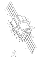
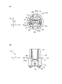
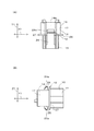
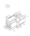
図1は、本発明の一実施形態に係る電気コネクタとしての第1コネクタ10を含む電気的接続装置1の正面図である。図2は、図1のII−II線に沿う電気的接続装置1の断面図である。図3は、電気的接続装置1の斜視図である。図4は、第1コネクタ10のハウジング11がパネル2に取り付けられた状態を示す斜視図である。図5は、第1コネクタ10のハウジング11の斜視図であり、ハウジング11の背面側を見た状態を示している。図6(A)は、ハウジング11の正面図である。図6(B)は、ハウジング11の側面図である。図7(A)は、ハウジング11の側面図であり、図6(B)で示す側面とは反対側の側面を示している。図7(B)は、ハウジング11の側面図であり、図6(B)に示す側面および図7(A)に示す側面とは90度向きが異なっている。
FIG. 1 is a front view of an electrical connection device 1 including a
図1〜図4(B)を参照して、電気的接続装置1は、複数の電気機器を電気的に接続するために用いられ、本実施形態では、第1電線3と第2電線4とを接続するワイヤートゥワイヤー式の電気的接続装置である。なお、電気的接続装置1は、基板と電線とを接続するボードトゥワイヤー式の電気的接続装置であってもよいし、基板と基板とを接続するボードトゥボード式の電気的接続装置であってもよい。
With reference to FIGS. 1 to 4 (B), the electrical connection device 1 is used to electrically connect a plurality of electric devices, and in the present embodiment, the first
電気的接続装置1は、パネル2に取り付けられる第1コネクタ10と、第1コネクタ10に接続される第2コネクタ80と、を有している。なお、パネル2が電気的接続装置1に含まれていてもよい。
The electrical connection device 1 has a
本実施形態では、各コネクタ10,80は、多極コネクタであり、本実施形態では、4極コネクタである。本実施形態では、各コネクタ10,80の幅方向、長さ方向および厚み方向をそれぞれ、幅方向X1、長さ方向Y1および厚み方向Z1という。
In this embodiment, each of the
パネル2は、第1コネクタ10を保持する部材である。パネル2は、平板状に形成されている。パネル2を構成する部材として、アルミニウム合金等の金属板、回路基板等を例示できる。パネル2は、例えば、図示しない筐体に固定されている。パネル2には、取付孔部2aが形成されている。取付孔部2aは、第1コネクタ10のハウジング11の後述する第1部分14を通過させることが可能な大きさに形成されている。本実施形態では、取付孔部2aは、円形状に形成されている。この取付孔部2aに、第1コネクタ10が取り付けられている。
The
第1コネクタ10は、被覆電線である第1電線3に接続されており、第2コネクタ80を介して第1電線3を第2電線4に接続する。
The
第2コネクタ80は、例えば、雄型コネクタであり、第1コネクタ10に接続されることでこの第1コネクタ10に保持される。第2コネクタ80は、被覆電線である第2電線4に接続されている。
The
第2コネクタ80は、ハウジング81と、ハウジング81に一体に形成されたロック片部82と、ハウジング81に保持された複数のコンタクト83と、を有している。
The
ハウジング81は、合成樹脂製の部材であり、射出成形によってロック片部82と一体成形されている。ハウジング81は、幅方向X1に扁平なブロック状に形成されている。ハウジング81には、複数の保持孔部84が形成されている。
The
保持孔部84は、コンタクト83を収容するために設けられており、ハウジング81を長さ方向Y1に貫通している。保持孔部84の数は、コンタクト83の数と同じであり、これらの保持孔部84が幅方向X1に略等間隔に並んでいる。
The holding
コンタクト83は、1つの保持孔部84に1つ収容されている。コンタクト83は、平板状の金属材料がプレス加工されることで形成された一体成形品である。コンタクト83は、保持孔部84内において、第2電線4の一端における芯線(金属線)にかしめ固定されており、この芯線と電気的且つ機械的に接続されている。コンタクト83には、筒状の接触部85が形成されている。接触部85は、第1コネクタ10のコンタクト11側を向いている。
One
ロック片部82は、第2コネクタ80を第1コネクタ10のハウジング11にロックするために設けられている。ロック片部82は、幅方向X1に扁平な板状に形成されており、ハウジング81の一側面に隣接して配置されている。ロック片部82は、小片状の支点部86を介してハウジング81に揺動可能に連結されている。支点部86は、ハウジング81およびロック片部82と一体成形されている。ロック片部82の先端には、ロック片部82の一側面からハウジング81側に突出するロック爪部87が形成されている。
The
次に、第1コネクタ10のより詳細な構成を説明する。
Next, a more detailed configuration of the
図1〜図7(B)を参照して、第1コネクタ10は、例えば、雌型コネクタであり、第2コネクタ80が差し込まれることでこの第2コネクタ80を保持する。第1コネクタ10は、被覆電線である第1電線3に接続されている。
With reference to FIGS. 1 to 7 (B), the
第1コネクタ10は、ハウジング11と、パネル2に形成された取付孔部2aにハウジング11を取り付けるためにハウジング11に設けられた取付機構12と、ハウジング11に保持された複数のコンタクト13と、を有している。
The
ハウジング11は、合成樹脂製の部材であり、射出成形によって取付機構12と一体成形されている。なお、ハウジング11は、取付機構12とは別部材によって形成されこの取付機構12と接着剤等を用いて互いに連結されてもよい。ハウジング11は、長さ方向Y1に沿う軸線を有する筒状に形成されている。
The
ハウジング11は、第1部分14と、第2部分15と、保持孔部16と、を有している。
The
第1部分14は、長さ方向Y1におけるハウジング11の略半部を構成している。ハウジング11がパネル2の取付孔部2aに取り付けられた取付状態(以下、単に取付状態ともいう。)において、第1部分14は、パネル2の表面2b側に突出している。第1部分14の外周面17は、略円筒状に形成されている。この外周面17は、取付状態において取付孔部2aと取付孔部2aの径方向に対向する対向部を含み、長さ方向Y1と直交する断面において円形状に形成されている。この外周面17の直径は、取付孔部2aの直径未満に設定されており、これにより、第1部分14は取付孔部2aを通過可能である。第1部分14の外周面には、窪み部14a,14bが形成されている。窪み部14a,14bは、第1部分14の外周面の周方向に例えば180度離隔して形成されている。窪み部14a,14bは、第1部分14の外周面17をこの外周面17の径方向内方に窪ませた形状に形成されている。窪み部14a,14bの底面は、長さ方向Y1と平行な平坦面を含んでいる。
The
窪み部14bには、ロック爪部18が設けられている。ロック爪部18は、第2コネクタ80のロック爪部87に係合するために設けられている。ロック爪部18は、窪み部14bの底面から突出する小片状に形成されている。上記の構成を有する第1部分14と長さ方向Y1に並んで第2部分15が配置されている。
The recessed
第2部分15は、長さ方向Y1におけるハウジング11の略半部を構成している。取付状態において、第2部分15は、パネル2の裏面2c側に突出している。第2部分15の外周面は、略四角形筒状に形成されている。
The
第2部分15の外周面には、窪み部14a,14bが形成されている。すなわち、窪み部14a,14bは、第1部分14から第2部分15に亘って設けられている。窪み部14a,14bは、第2部分15の外周面の周方向に例えば180度離隔して形成されている。第2部分15では、当該第2部分15の外周面のうちの2面が、窪み部14a,14bを形成している。窪み部14a,14bは、第2部分15の外周面をこの外周面の内側に窪ませた形状に形成されている。窪み部14a,14bの底面は、第2部分15においても、長さ方向Y1と平行な平坦面を含んでいる。
Recessed
保持孔部16は、第1部分14および第2部分15にかけて形成されており、第2コネクタ80の一部を収容するとともに、コンタクト13を収容する部分である。保持孔部16は、ハウジング11を長さ方向Y1に貫通している。
The holding
保持孔部16は、第2コネクタ嵌合部19と、複数のコンタクト保持孔部20と、を有している。
The holding
第2コネクタ嵌合部19は、第1部分14に形成されており、第1部分14の一端面に開放されている。第2コネクタ嵌合部19は、第2コネクタ80のハウジング81の外形形状に対応する形状(例えば、略四角形筒状)に形成されており、ハウジング81の先端側の一部を収容可能である。第2コネクタ嵌合部19に連続するように、コンタクト保持孔部20が形成されている。
The second
コンタクト保持孔部20は、コンタクト13を収容するために設けられており、ハウジング11の第2部分15に形成されて第2部分15の一端面に開放されている。コンタクト保持孔部20の数は、コンタクト13の数と同じであり、これらのコンタクト保持孔部20が幅方向X1に略等間隔に並んでいる。隣り合うコンタクト保持孔部20間には、長さ方向Y1に延びる隔壁21が形成されている。これらのコンタクト保持孔部20は、何れも、第2コネクタ嵌合部19に連続している。
The
コンタクト13は、1つのコンタクト保持孔部20に1つ収容されている。コンタクト13は、平板状の金属材料がプレス加工されることで形成された一体成形品である。コンタクト13は、コンタクト保持孔部20内において、第1電線3の一端における芯線(金属線)にかしめ固定されており、この芯線と電気的且つ機械的に接続されている。コンタクト13には、棒状の接触部22が形成されている。接触部22は、第2コネクタ嵌合部19に突出しており、第2コネクタ80のコンタクト83の接触部85に挿入されることでこの接触部85に接触する。
One
各コンタクト13は、対応するコンタクト保持孔部20に固定されている。本実施形態では、各コンタクト13,83の接触部22,85は、長さ方向Y1におけるパネル2の表面2b側で互いに接触している。また、コンタクト13のうち保持孔部16に固定される被固定部23は、パネル2(取付機構12)に取り囲まれる箇所に配置されている。この構成により、コンタクト13を介してハウジング11に作用する荷重は、取付機構12およびパネル2にバランスよく受けられる。これにより、第1コネクタ10がパネル2に対して傾く(長さ方向Y1がパネル2と垂直な方向から傾く)ことをより確実に抑制できる。各コンタクト13に接続された第1電線3は、対応するコンタクト保持孔部20を通してハウジング11の内部から外部に延びている。
Each
次に、取付機構12について、より詳細に説明する。
Next, the mounting
取付機構12は、ハウジング11が取付孔部2aに取り付けられた取付状態において取付孔部2aの周方向C1に関してハウジング11をパネル2に対して回転自在に取り付けている。また、取付機構12は、パネル2に対するハウジング11の位置ずれを許容するようにハウジング11を取付孔部2aに取り付ける。
The mounting
取付機構12は、第1弾性爪部24,25と、第1弾性爪部24,25と協働してパネル2を挟む挟み部26,27と、を有している。
The mounting
第1弾性爪部24,25は、ハウジング11に支持され弾性変形可能な小片状部材である。第1弾性爪部24,25は、ハウジング11が取付孔部2aに着脱されるときに弾性変形するように構成されているとともに、取付状態においてハウジング11が取付孔部2aに対して位置ずれするときに弾性変形するように構成されている。
The first
第1弾性爪部24,25は、1または複数(本実施形態では、2つ)設けられている。各第1弾性爪部24,25は、矩形の板状に形成された板ばね部材である。各第1弾性爪部24,25は、ハウジング11の第2部分15の対応する窪み部14a,14b内において、第2部分15の一端に固定された片持ち部材であり、長さ方向Y1に沿って第1部分14側に延びている。第1弾性爪部24,25の大部分は、対応する窪み部14a,14b内に配置されている。第1弾性爪部24,25の先端は、厚み方向Z1において第1部分14と向き合う箇所に配置されている。第1弾性爪部24,25の先端部には、フック部24a,25aが設けられている。フック部24a,25aは、対応する窪み部14a,14bから第1部分14の外側に向けて突出する部分であり、取付孔部2aの縁部(表面2b)に受けられる部分である。フック部24a,25aのうち、パネル2の表面2bに接触する部分は、平坦である。一方、フック部24a,25aのうち、第1弾性爪部24,25の先端部は、先端に向かうに従い先細りとなる形状に形成されている。
The first
挟み部26,27は、ハウジング11の第1部分14の外周面17に形成されており、第1部分14から突出した形状に形成されている。本実施形態では、挟み部26,27は、ハウジング11の外周面から突出するフランジ部であり、それぞれ、円弧状の板状部分である。挟み部26,27のうち、パネル2の裏面2cに接触する部分は、平坦である。挟み部26,27は、ハウジング11の周方向C1において第1弾性爪部24,25と離隔して配置されている。そして、本実施形態では、第1弾性爪部24,25および挟み部26,27は、周方向C1に沿って、第1弾性爪部24、挟み部26、第1弾性爪部25、および、挟み部27の順に配列されている。周方向C1において、挟み部26(27)の長さは、第1弾性爪部24(25)の長さよりも長い。長さ方向Y1におけるフック部24a,25aと挟み部26,27との距離は、パネル2の厚みと略同じに設定されている。
The sandwiching
次に、電気的接続装置1の組立作業を説明する。 Next, the assembly work of the electrical connection device 1 will be described.
電気的接続装置1が組み立てられる際には、まず、作業員は、第1電線3が接続された第1コネクタ10を、パネル2の取付孔部2aに挿入する。このとき、作業員は、第1コネクタ10のハウジング11の第1部分14を取付孔部2aに通すとともに、第1弾性爪部24,25のフック部24a,25aを対応する窪み部14a,14b内に押し込む。
When the electrical connection device 1 is assembled, the worker first inserts the
フック部24a,25aが取付孔部2aを通過すると、第1弾性爪部24,25の復元力によってフック部24a,25aが取付孔部2aの外側に配置され、フック部24a,25aは、取付孔部2aの周囲におけるパネル2の表面2bに向かい合う。このとき、挟み部26,27は、パネル2の裏面2cに受けられる。これにより、第1弾性爪部24,25および挟み部26,27でパネル2が挟まれ、その結果、パネル2への第1コネクタ10の取付が完了する。このとき、第1コネクタ10のハウジング11と取付孔部2aとの間には、ハウジング11を取付孔部2aの周方向C1回りに回転規制する構成が設けられていない。このため、取付状態においても、ハウジング11は、取付孔部2aに対して周方向C1に回転(位置調整)自在である。
When the
取付状態において、第1弾性爪部24,25は、取付孔部2aの縁部に押し付けられるように配置される。これにより、第1弾性爪部24,25は、取付状態において取付孔部2aとハウジング11との間で弾性変形可能である。例えば、ハウジング11が取付孔部2aに対して長さ方向Y1と直交する方向に変位したとき、第1弾性爪部24,25の弾性変形量が変化しつつ、ハウジング11が取付孔部2aに対して変位する。これにより、ハウジング11は、取付孔部2aに対する位置ずれを許容される。
In the mounted state, the first
次に、第1コネクタ10に第2コネクタ80を取り付ける際には、作業員は、第2電線4が取り付けられた第2コネクタ80のハウジング81を、ハウジング11の第2コネクタ嵌合部19に挿入する。ハウジング11へのハウジング81の挿入量が所定量に達すると、第2コネクタ80のロック片部82の揺動に伴い、ロック爪部87が第1ハウジング11のロック爪部18に係合する。これにより、ハウジング11,81が互いにロックされる。また、第2コネクタ80のコンタクト83の接触部85に第1コネクタ10のコンタクト13の接触部22が挿入されてこれらの接触部22,85が電気的に接続される。
Next, when attaching the
なお、第2コネクタ80を第1コネクタ10から取り外す際には、作業員は、ロック片部82を押してこのロック片部82を揺動させることで、ロック爪部18,87の係合を解除する。このロック解除状態のまま、作業員が第2コネクタ80を第1コネクタ10から引き抜くことで、第2コネクタ80を第1コネクタ10から取り外すことができる。
When removing the
また、第1コネクタ10をパネル2から取り外す際には、作用員は、第1弾性爪部24,25を対応する窪み部14a,14b側に向けて押し込む。これにより、第1弾性爪部24,25は、対応する窪み部14a,14bに収容され、第1弾性爪部24,25のフック部24a,25aとパネル2の表面2bとの係合が解除される。この状態で、作業員は、第1コネクタ10を取付孔部2a側(裏面2c側)へ押し出すことで、第1部分14がパネル2から抜かれ、これにより、パネル2からの第1コネクタ10の取り外しが完了する。
Further, when the
以上説明したように、本実施形態によると、ハウジング11は、取付状態においてパネル2に対して回転自在である。これにより、パネル2へのハウジング11の取付が完了した後でも、ハウジング11をパネル2に対して位置調整可能である。
As described above, according to the present embodiment, the
また、本実施形態によると、ハウジング11の外周面17は断面円形状に形成されている。この構成によると、ハウジング11を取付孔部2aに対して回転させやすくできる。よって、取付状態において、パネル2に対するハウジング11の位置調整をより容易に行える。
Further, according to the present embodiment, the outer
また、本実施形態によると、取付機構12は、パネル2に対するハウジング11の着脱時に弾性変形しつつ取付孔部2aに係合する第1弾性爪部24,25と、この第1弾性爪部24,25と協働してパネル2を挟む挟み部26,27と、を有している。この構成によると、作業者が第1弾性爪部24,25を取付孔部2aに押し込むことで、第1弾性爪部24,25を取付孔部2aの縁部に取り付けることができる。これにより、取付孔部2aへのハウジング11の取り付け作業をより容易に行うことができる。
Further, according to the present embodiment, the mounting
また、本実施形態によると、挟み部26,27は、ハウジング11の外周面から突出するフランジ部を含んでいる。この構成によると、第1弾性爪部24,25と挟み部26,27とで確実にパネル2を挟むことができる。これにより、ハウジング11を、パネル2により堅固に取り付けることができる。
Further, according to the present embodiment, the sandwiching
また、本実施形態によると、第1弾性爪部24,25は、取付状態において取付孔部2aとハウジング11との間で弾性変形可能に配置されている。この構成によると、第1弾性爪部24,25がハウジング11と取付孔部2aとの間で弾性変形可能であることにより、ハウジング11をパネル2にフローティング支持可能である。これにより、ハウジング11と取付孔部2aとが相対変位可能であるので、ハウジング11と取付孔部2aとの位置ずれを許容することができる。
Further, according to the present embodiment, the first
[変形例]
以上、本発明の実施形態について説明したけれども、本発明は上述の実施の形態に限られず、特許請求の範囲に記載した限りにおいて様々な変更が可能である。例えば、次のように変更して実施してもよい。
[Modification example]
Although the embodiments of the present invention have been described above, the present invention is not limited to the above-described embodiments, and various modifications can be made as long as they are described in the claims. For example, the following changes may be made.
(1)前述の実施形態では、取付機構12が第1弾性爪部24,25と挟み部26,27とを有する形態を例に説明した。しかしながら、この通りでなくてもよい。例えば、第1弾性爪部24,25と、第2弾性爪部28,29と、を有する取付機構12Aが設けられてもよい。
(1) In the above-described embodiment, the embodiment in which the mounting
尚、以下では、上述の実施形態と異なる構成について主に説明し、上述の実施形態と同様の構成については、図に同様の符号を付して説明を省略する。 In the following, configurations different from those of the above-described embodiment will be mainly described, and the same configurations as those of the above-described embodiments are designated by the same reference numerals and the description thereof will be omitted.
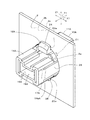
図8は、ハウジング11の変形例であるハウジング11Aがパネル2に取り付けられた状態を示す斜視図である。図9は、ハウジング11Aの斜視図であり、図8に示す向きとは別の向きを示している。図10(A)は、ハウジング11Aの正面図であり、図10(B)は、ハウジング11Aの側面図である。
FIG. 8 is a perspective view showing a state in which the
図8〜図10(B)を参照して、この変形例では、ハウジング11Aに代えてハウジング11Aおよび取付機構12Aが用いられる。ハウジング11Aは、図示しない第2コネクタ80が差し込まれることでこの第2コネクタ80を保持する。ハウジング11Aには、図示しないコンタクト13が収容される。このコンタクト13は、被覆電線である第1電線3に接続されている。
With reference to FIGS. 8 to 10 (B), in this modification, the
ハウジング11Aは、合成樹脂製の部材であり、射出成形によって取付機構12Aと一体成形されている。なお、ハウジング11Aは、取付機構12Aとは別部材によって形成されこの取付機構12Aとは接着剤等を用いて互いに連結されていてもよい。ハウジング11Aは、長さ方向Y1に沿う軸線を有する筒状に形成されている。
The
ハウジング11Aは、第1部分14Aと、第2部分15Aと、保持孔部16Aと、を有している。
The
第1部分14Aは、長さ方向Y1におけるハウジング11Aの略半部を構成している。取付状態において、第1部分14Aは、パネル2の表面2b側に突出している。第1部分14Aの外周面17Aは、略四角形筒状に形成されている。長さ方向Y1からみて、第1部分14Aの全体が、取付孔部2a内に配置されている。この構成により、第1部分14Aを取付孔部2aに通すことができる。
The
第1部分14Aの外周面17Aには、窪み部14aA,14bAが形成されている。窪み部14aA,14bAは、第1部分14Aの外周面17Aの周方向に例えば180度離して2箇所に形成されている。第1部分14Aでは、当該第1部分14Aの外周面17Aのうちの2面が、窪み部14aA,14bAを形成している。窪み部14aA,14bAは、第1部分14Aの外周面17Aをこの外周面17Aの内側に窪ませた形状に形成されている。上記の構成を有する第1部分14Aと長さ方向Y1に並んで第2部分15Aが配置されている。
Recessed portions 14aA and 14bA are formed on the outer
第2部分15Aは、長さ方向Y1におけるハウジング11Aの略半部を構成している。取付状態において、第2部分15Aは、パネル2の裏面2c側に突出している。第2部分15Aの外周面は、略四角形筒状に形成されている。長さ方向Y1からみて、第2部分15Aの全体が、取付孔部2a内に配置されている。この構成により、第2部分15Aを取付孔部2aに通すことができる。すなわち、ハウジング11Aは、第1部分14Aを取付孔部2aに挿入することで取付孔部2aに取り付けられることが可能であり、且つ、第2部分15Aを取付孔部2aに挿入することで取付孔部2aに取り付けられることも可能である。
The
第2部分15Aの外周面には、窪み部15aA,15bAが形成されている。窪み部15aA,15bAは、第2部分15Aの外周面の周方向に例えば180度離して2箇所に形成されている。窪み部14aA,14bAと窪み部15aA,15bAとは、周方向C1の位置が90度ずらされている。第2部分15Aでは、当該第2部分15Aの外周面のうちの2面が、窪み部15aA,15bAを形成している。窪み部15aA,15bAは、第2部分15Aの外周面をこの外周面の内側に窪ませた形状に形成されている。
Recessed portions 15aA and 15bA are formed on the outer peripheral surface of the
保持孔部16Aは、第1部分14Aおよび第2部分15Aに亘って形成されており、図示しない第2コネクタ80の一部を収容するとともに、図示しないコンタクト13を収容する部分である。保持孔部16Aは、ハウジング11Aを長さ方向Y1に貫通している。
The holding
保持孔部16Aは、第2コネクタ80のハウジング81が挿入される第2コネクタ嵌合部19Aと、コンタクト13が挿入される複数のコンタクト保持孔部20Aと、を有している。
The holding
第2コネクタ嵌合部19Aは、第1部分14Aに形成されており、第1部分14Aの一端面に開放されている。第2コネクタ嵌合部19Aに連続するように、コンタクト保持孔部20Aが形成されている。
The second
コンタクト保持孔部20Aは、ハウジング11Aの第2部分15Aに形成されて第2部分15Aの一端面に開放されている。
The contact holding
次に、取付機構12Aについて、より詳細に説明する。
Next, the mounting
取付機構12Aは、ハウジング11Aが取付孔部2aに取り付けられた取付状態において取付孔部2aの周方向C1に関してハウジング11Aをパネル2に対して回転自在に取り付けられている。また、取付機構12Aは、パネル2に対するハウジング11Aの位置ずれを許容するようにハウジング11Aを取付孔部2aに取り付ける。
In the
取付機構12Aは、第1弾性爪部24,25と、第1弾性爪部24,25と協働してパネル2を挟む挟み部としての第2弾性爪部28,29と、を有している。
The mounting
第1弾性爪部24,25は、ハウジング11Aに支持され弾性変形可能な小片状部材である。第1弾性爪部24,25は、ハウジング11Aが取付孔部2aに着脱されるときに弾性変形するように構成されているとともに、取付状態においてハウジング11Aが取付孔部2aに対して位置ずれするときに弾性変形するように構成されている。
The first
第1弾性爪部24,25は、1または複数(本実施形態では、2つ)設けられている。各第1弾性爪部24,25は、矩形の板状に形成された板ばね部材である。各第1弾性爪部24,25は、ハウジング11Aの第2部分15Aの対応する窪み部15aA,15bA内において、第2部分15Aの一端に固定された片持ち部材であり、長さ方向Y1に沿って第1部分14A側に延びている。第1弾性爪部24,25の大部分は、対応する窪み部15aA,15bA内に配置されている。第1弾性爪部24,25のフック部24a,25aは、対応する窪み部15aA,15bAから第2部分15Aの外側に向けて突出しており、取付孔部2aの縁部(表面2b)に受けられる。
The first
第2弾性爪部28,29は、第1弾性爪部24,25とはパネル2に対する差し込み方向が反対に設定されている。第2弾性爪部28,29は、ハウジング11Aに支持され弾性変形可能な小片状部材である。第2弾性爪部28,29は、ハウジング11Aが取付孔部2aに着脱されるときに弾性変形しつつ取付孔部2aに係合するように構成されているとともに、取付状態においてハウジング11Aが取付孔部2aに対して位置ずれするときに弾性変形するように構成されている。
The second
第2弾性爪部28,29は、1または複数(本実施形態では、2つ)設けられている。各第2弾性爪部28,29は、矩形の板状に形成された板ばね部材であり、第1弾性爪部24,25と同様の形状に形成されている。各第2弾性爪部28,29は、ハウジング11Aの第1部分14Aの対応する窪み部14aA,14bA内において、第1部分14Aの一端に固定された片持ち部材であり、長さ方向Y1に沿って第2部分15A側に延びている。第2弾性爪部28,29の大部分は、対応する窪み部14aA,14bA内に配置されている。
The second
第2弾性爪部28,29の先端部には、フック部28a,29aが設けられている。フック部28a,29aは、対応する窪み部14aA,14bAから第1部分14Aの外側に向けて突出する部分であり、取付孔部2aの縁部(裏面2c)に受けられる部分である。フック部28a,29aのうち、パネル2の表面2bに接触する部分は、平坦である。一方、フック部28a,29aのうち、第2弾性爪部28,29の先端部は、先端に向かうに従い先細りとなる形状に形成されている。長さ方向Y1におけるフック部24a,25aと、フック部28a,29aと、の距離は、パネル2の厚みと略同じに設定されている。
第2弾性爪部28,29は、ハウジング11Aの周方向C1において第1弾性爪部24,25と離隔して配置されている。そして、本実施形態では、第1弾性爪部24,25および第2弾性爪部28,29は、周方向C1に沿って、第1弾性爪部24、第2弾性爪部28、第1弾性爪部25、および、第2弾性爪部29の順に配列されている。
The second
次に、ハウジング11Aをパネル2に着脱する作業を説明する。
Next, the work of attaching / detaching the
ハウジング11Aをパネル2に取り付ける際には、例えば、作業員は、ハウジング11Aの例えば第1部分14Aを、パネル2の取付孔部2aに挿入する。このとき、作業員は、例えば、フック部24a,25aを対応する窪み部15aA,15bA内に押し込む。これにより、第1部分14Aが取付孔部2aに挿入されると、第1弾性爪部24,25のフック部24a,25aは、取付孔部2aを通過し、その後、第1弾性爪部24,25の復元力によってフック部24a,25aが取付孔部2aの外側に配置される。これにより、フック部24a,25aは、取付孔部2aの周囲におけるパネル2の表面2bに向かい合う。
When attaching the
このとき、第2弾性爪部28,29のフック部28a,29aは、パネル2の裏面2cに受けられる。これにより、第1弾性爪部24,25および第2弾性爪部28,29でパネル2が挟まれ、その結果、パネル2へのハウジング11Aの取付が完了する。このとき、ハウジング11Aおよび取付機構12Aと、取付孔部2aと、の間には、ハウジング11Aを取付孔部2aの周方向C1回りに回転規制する構成が設けられていない。このため、ハウジング11Aが取付孔部2aに取り付けられた後においても、ハウジング11Aは、取付孔部2aに対して周方向C1に回転(位置調整)自在である。
At this time, the
なお、ハウジング11Aをパネル2に取り付ける際には、作業員は、ハウジング11Aの第2部分15Aを、パネル2の取付孔部2aに挿入してもよい。このとき、作業員は、フック部28a,29aを、対応する窪み部14aA,14bA内に押し込む。これにより、第2部分15Aが取付孔部2aに挿入されると、第2弾性爪部28,29のフック部28a,29aは、取付孔部2aを通過し、その後、第2弾性爪部28,29の復元力によってフック部28a,29aが取付孔部2aの外側に配置される。これにより、フック部28a,29aは、取付孔部2aの周囲におけるパネル2の裏面2cに向かい合う。このとき、第1弾性爪部24,25のフック部24a,25aは、パネル2の表面2bに受けられる。これにより、第1弾性爪部24,25および第2弾性爪部28,29でパネル2が挟まれ、その結果、パネル2へのハウジング11Aの取付が完了する。
When attaching the
取付状態において、第1弾性爪部24,25および第2弾性爪部28,29は、取付孔部2aの縁部に押し付けられるように配置される。これにより、第1弾性爪部24,25および第2弾性爪部28,29は、取付孔部2aに取り付けられているときに取付孔部2aとハウジング11との間で弾性変形可能である。例えば、ハウジング11Aが取付孔部2aに対して長さ方向Y1と直交する方向に変位したとき、第1弾性爪部24,25の弾性変形量および第2弾性爪部28,29の弾性変形量が変化しつつ、ハウジング11Aが取付孔部2aに対して変位する。
In the mounted state, the first
ハウジング11Aをパネル2から取り外す際には、作用員は、例えば第1弾性爪部24,25をハウジング11A側に向けて押し込む。これにより、第1弾性爪部24,25は、対応する窪み部15aA,15bAに収容され、第1弾性爪部24,25のフック部24a,25aとパネル2の表面2bとの係合が解除される。この状態で、作業員は、ハウジング11Aの第1部分14Aをパネル2から押し出すことで、第1部分14Aがパネル2から抜かれ、これにより、パネル2からのハウジング11Aの取り外しが完了する。
When removing the
なお、ハウジング11Aをパネル2から取り外す際には、作用員は、第2弾性爪部28,29をパネル2から押し出してもよい。この場合、第2弾性爪部28,29は、対応する窪み部14aA,14bAに収容され、第2弾性爪部28,29のフック部28a,29aとパネル2の裏面2cとの係合が解除される。この状態で、作業員は、ハウジング11Aの第2部分15Aをパネル2から押し出すことで、第2部分15Aがパネル2から抜かれ、これにより、パネル2からのハウジング11Aの取り外しが完了する。
When removing the
この構成においても、上述の実施形態と同様の効果を発揮できる。 Even in this configuration, the same effect as that of the above-described embodiment can be exhibited.
また、この構成によると、ハウジング11Aをパネル2の表面2b側から取付孔部2aに取り付けることができるとともに、ハウジング11Aをパネル2の裏面2c側から取付孔部2aに取り付けることができる。すなわち、ハウジング11Aをパネル2の表面2b側および裏面2c側の何れからもパネル2に取り付けることができる。これにより、パネル2へのハウジング11Aの取付の自由度をより高くできる。例えば、第1弾性爪部24,25を弾性変形させつつ取付孔部2aに取り付けることで、ハウジング11Aをパネル2の裏面2c側から取付孔部2aに取り付けることができる。また、第2弾性爪部28,29を弾性変形させつつ取付孔部2aに取り付けることで、ハウジング11をパネル2の表面2b側から取付孔部2aに取り付けることができる。
Further, according to this configuration, the
(2)なお、上述の変形例において、図11に示すように、長さ方向Y1において第1弾性爪部24,25と第2弾性爪部28,29との間に挟み部26Aが設けられていてもよい。挟み部26Aは、ハウジング11Aの外周部に形成されており、例えば、第1部分14Aから突出した形状に形成されている。挟み部26Aは、ハウジング11Aの外周面から突出するフランジ部であり、例えば、周方向C1に並ぶ複数の円弧板状部分を有している。長さ方向Y1における挟み部26Aの両端面は、平坦である。長さ方向Y1において、第1弾性爪部24,25と挟み部26Aとの間隔は、パネル2の厚みと略同じに設定されている。同様に、長さ方向Y1において、第2弾性爪部28,29と挟み部26Aとの間隔は、パネル2の厚みと略同じに設定されている。
(2) In the above-mentioned modified example, as shown in FIG. 11, a sandwiching
この構成において、パネル2をハウジング11Aに取り付ける場合、作業員は、例えば、第1部分14Aを取付孔部2aに差し込む。これにより、第1弾性爪部24,25は、撓みながら取付孔部2aを通過した後、取付孔部2aの縁部に係合し、挟み部26Aと協働してパネル2を挟む。また、パネル2をハウジング11Aに取り付ける場合、作業員は、例えば、第2部分15Aを取付孔部2aに差し込んでもよい。この場合、第2弾性爪部28,29は、撓みながら取付孔部2aを通過した後、取付孔部2aの縁部に係合し、挟み部26Aと協働してパネル2を挟む。
In this configuration, when the
(3)また、前述の実施形態および変形例では、取付孔部2aが丸孔である形態を例に説明した。しかしながら、この通りでなくてもよい。取付孔部2aは、ハウジング11,11Aを回転自在に嵌合可能であればよく、例えば、多角形形状の孔であってもよい。
(3) Further, in the above-described embodiment and modification, the embodiment in which the mounting
(4)また、前述の実施形態および変形例では、第1弾性爪部24,25および第2弾性爪部28,29が、撓んだ状態で取付孔部2aに取り付けられる形態を例に説明した。しかしながら、この通りでなくてもよい。例えば、第1弾性爪部24,25および第2弾性爪部28,29は、撓まない状態で取付孔部2aに取り付けられてもよい。
(4) Further, in the above-described embodiments and modifications, the first
(5)また、前述の実施形態および変形例では、第1コネクタは、コンタクト13を直接保持する形態を例に説明した。しかしながら、この通りでなくてもよい。例えば、ハウジング11,11Aに、コンタクトおよびこのコンタクトを保持するハウジングを有する電気コネクタの当該ハウジングが嵌合されてもよい。この場合、ハウジング11,11Aは、中継コネクタとして機能する。
(5) Further, in the above-described embodiment and modification, the first connector directly holds the
本発明は、電気コネクタとして、広く適用することができる。 The present invention can be widely applied as an electric connector.
2 パネル
2a 取付孔部
10 第1コネクタ(電気コネクタ)
11,11A ハウジング
12,12A 取付機構
17 ハウジングの外周面(対向部)
24,25 第1弾性爪部(弾性爪部)
26,27,26A 挟み部
28,29 第2弾性爪部
C1 取付孔部の周方向
2
11,
24, 25 1st elastic claw part (elastic claw part)
26,27,26A Sandwiched
Claims (2)
パネルに形成された取付孔部に前記ハウジングを取り付けるために前記ハウジングに設けられた取付機構と、
を備え、
前記取付機構は、前記ハウジングが前記取付孔部に取付られた取付状態において前記取付孔部の周方向に関して前記ハウジングを前記パネルに対して回転自在に取り付けており、
前記ハウジングの外周面は、前記取付状態において前記取付孔部に対向する対向部を含み、
前記対向部は、断面円形状に形成されており、
前記取付機構は、前記パネルに対する前記ハウジングの着脱時に弾性変形しつつ前記取付孔部に係合する弾性爪部と、この弾性爪部と協働して前記パネルを挟む挟み部と、を有しており、
前記ハウジングの外周面において、当該ハウジングの内側に窪む第1の窪み部と第2の窪み部とが形成されており、
前記第1の窪み部は、前記ハウジングの外周面の周方向に180度離れて2か所に形成されており、
前記第2の窪み部は、前記ハウジングの外周面の周方向に180度離れて2か所に形成されており、
前記第1の窪み部と前記第2の窪み部とは、前記ハウジングの外周面の周方向の位置が90度ずらされて設けられており、
前記弾性爪部は、2つ設けられており、各前記弾性爪部は、各前記第1の窪み部内において端部が前記ハウジングに固定されて前記ハウジングの長さ方向に延びる片持ち部材として設けられ、
各前記弾性爪部の先端部には、各前記第1の窪み部から前記ハウジングの外側に向けて突出するフック部が設けられ、前記フック部が前記取付孔部の縁部に受けられることで前記フック部と前記取付孔部の縁部とが係合し、
前記挟み部は、前記弾性爪部とは前記パネルに対する差し込み方向が反対に設定されているとともに、前記パネルに対する前記ハウジングの着脱時に弾性変形しつつ前記取付孔部に係合する第2弾性爪部を含み、
前記第2弾性爪部は、2つ設けられており、各前記第2弾性爪部は、各前記第2の窪み部内において端部が前記ハウジングに固定されて前記ハウジングの長さ方向に延びる片持ち部材として設けられ、
各前記第2弾性爪部の先端部には、各前記第2の窪み部から前記ハウジングの外側に向けて突出する第2のフック部が設けられ、前記第2のフック部が前記取付孔部の縁部に受けられることで前記第2のフック部と前記取付け孔部の縁部とが係合することを特徴とする、電気コネクタ。 With the housing
A mounting mechanism provided in the housing for mounting the housing in the mounting holes formed in the panel, and
Equipped with
The mounting mechanism rotatably mounts the housing with respect to the panel in the circumferential direction of the mounting hole in a mounting state in which the housing is mounted to the mounting hole.
The outer peripheral surface of the housing includes a facing portion facing the mounting hole portion in the mounting state.
The facing portion is formed in a circular cross section and has a circular cross section.
The mounting mechanism has an elastic claw portion that is elastically deformed when the housing is attached to and detached from the panel and engages with the mounting hole portion, and a sandwiching portion that cooperates with the elastic claw portion to sandwich the panel. And
On the outer peripheral surface of the housing, a first recessed portion and a second recessed portion recessed inside the housing are formed.
The first recesses are formed at two locations 180 degrees apart in the circumferential direction of the outer peripheral surface of the housing.
The second recesses are formed at two locations 180 degrees apart in the circumferential direction of the outer peripheral surface of the housing.
The first recessed portion and the second recessed portion are provided so that the positions of the outer peripheral surface of the housing in the circumferential direction are shifted by 90 degrees.
Two elastic claws are provided, and each elastic claw is provided as a cantilever member whose end is fixed to the housing and extends in the length direction of the housing in each of the first recesses. Be,
The tip of each elastic claw portion is provided with a hook portion that protrudes from each of the first recessed portions toward the outside of the housing, and the hook portion is received by the edge portion of the mounting hole portion. and the edge of the mounting hole portion and the hook portion is engaged,
The sandwiching portion is set in the direction opposite to that of the elastic claw portion in the insertion direction with respect to the panel, and the second elastic claw portion engages with the mounting hole portion while being elastically deformed when the housing is attached to and detached from the panel. Including
Two second elastic claws are provided, and each of the second elastic claws is a piece whose end is fixed to the housing and extends in the length direction of the housing in each of the second recesses. Provided as a holding member,
A second hook portion is provided at the tip of each of the second elastic claw portions so as to project from each of the second recessed portions toward the outside of the housing, and the second hook portion is the mounting hole portion. An electric connector characterized in that the second hook portion and the edge portion of the mounting hole portion are engaged with each other by being received by the edge portion of the housing.
前記弾性爪部は、前記取付状態において前記取付孔部と前記ハウジングとの間で弾性変形可能に配置されていることを特徴とする、電気コネクタ。 The electric connector according to claim 1.
An electric connector, characterized in that the elastic claw portion is elastically deformably arranged between the mounting hole portion and the housing in the mounting state.
Priority Applications (1)
| Application Number | Priority Date | Filing Date | Title |
|---|---|---|---|
| JP2017098363A JP6973773B2 (en) | 2017-05-17 | 2017-05-17 | Electrical connector |
Applications Claiming Priority (1)
| Application Number | Priority Date | Filing Date | Title |
|---|---|---|---|
| JP2017098363A JP6973773B2 (en) | 2017-05-17 | 2017-05-17 | Electrical connector |
Publications (2)
| Publication Number | Publication Date |
|---|---|
| JP2018195456A JP2018195456A (en) | 2018-12-06 |
| JP6973773B2 true JP6973773B2 (en) | 2021-12-01 |
Family
ID=64571876
Family Applications (1)
| Application Number | Title | Priority Date | Filing Date |
|---|---|---|---|
| JP2017098363A Active JP6973773B2 (en) | 2017-05-17 | 2017-05-17 | Electrical connector |
Country Status (1)
| Country | Link |
|---|---|
| JP (1) | JP6973773B2 (en) |
Family Cites Families (5)
| Publication number | Priority date | Publication date | Assignee | Title |
|---|---|---|---|---|
| US3989343A (en) * | 1976-01-27 | 1976-11-02 | Amp Incorporated | Means for mounting an electrical connector in a panel opening from either side of the panel |
| JPS56143786U (en) * | 1980-03-29 | 1981-10-29 | ||
| JPS60115184A (en) * | 1983-11-28 | 1985-06-21 | 富士ゼロックス株式会社 | Connector for corona discharger |
| JP3884446B2 (en) * | 2004-04-14 | 2007-02-21 | 古河電気工業株式会社 | Connector with lock |
| JP6156929B2 (en) * | 2013-10-10 | 2017-07-05 | タイコエレクトロニクスジャパン合同会社 | connector |
-
2017
- 2017-05-17 JP JP2017098363A patent/JP6973773B2/en active Active
Also Published As
| Publication number | Publication date |
|---|---|
| JP2018195456A (en) | 2018-12-06 |
Similar Documents
| Publication | Publication Date | Title |
|---|---|---|
| JP4262740B2 (en) | Optical connector | |
| JP4412739B2 (en) | Optical connector assembly jig | |
| JP5557236B2 (en) | Electrical connector | |
| WO2012086116A1 (en) | Lever-type connector, and wire cover | |
| JP6914232B2 (en) | Connector structure | |
| JP2020516042A (en) | Connector device having connector and assembly method | |
| JP4683577B2 (en) | Unlocking device and connector device | |
| US7513794B2 (en) | Clamp/plug connector for through-wall connection having wedge-shaped attachment | |
| JP2005134822A (en) | Optical connector adaptor | |
| JP6931223B2 (en) | Terminals and electrical connectors | |
| JPH08213085A (en) | Lockable flat socket for electric connection | |
| KR101530431B1 (en) | Connector device | |
| JP6973773B2 (en) | Electrical connector | |
| JP4052171B2 (en) | Fast connection terminal device | |
| JP4891714B2 (en) | Wire cover lock structure | |
| JP4949847B2 (en) | Clamp for holding a cable extending from the electrical connector, and electrical connector provided with the clamp | |
| JP3533692B2 (en) | Connection device | |
| TWI236866B (en) | Wiring tools | |
| JPH0236218Y2 (en) | ||
| JP2013232337A (en) | Joint connector, and connection terminal connecting structure | |
| JPH08167460A (en) | Socket for fluorescent lamp | |
| JP4052170B2 (en) | Fast connection terminal device | |
| JPH1167343A (en) | Connector fitting and removing structure | |
| JP2005174823A (en) | Connector mounting bracket | |
| JP2019057452A (en) | connector |
Legal Events
| Date | Code | Title | Description |
|---|---|---|---|
| RD02 | Notification of acceptance of power of attorney |
Free format text: JAPANESE INTERMEDIATE CODE: A7422 Effective date: 20191107 |
|
| A621 | Written request for application examination |
Free format text: JAPANESE INTERMEDIATE CODE: A621 Effective date: 20200501 |
|
| A977 | Report on retrieval |
Free format text: JAPANESE INTERMEDIATE CODE: A971007 Effective date: 20210129 |
|
| A131 | Notification of reasons for refusal |
Free format text: JAPANESE INTERMEDIATE CODE: A131 Effective date: 20210209 |
|
| A521 | Written amendment |
Free format text: JAPANESE INTERMEDIATE CODE: A523 Effective date: 20210329 |
|
| A02 | Decision of refusal |
Free format text: JAPANESE INTERMEDIATE CODE: A02 Effective date: 20210622 |
|
| A521 | Written amendment |
Free format text: JAPANESE INTERMEDIATE CODE: A523 Effective date: 20210915 |
|
| C60 | Trial request (containing other claim documents, opposition documents) |
Free format text: JAPANESE INTERMEDIATE CODE: C60 Effective date: 20210915 |
|
| A911 | Transfer to examiner for re-examination before appeal (zenchi) |
Free format text: JAPANESE INTERMEDIATE CODE: A911 Effective date: 20210924 |
|
| C21 | Notice of transfer of a case for reconsideration by examiners before appeal proceedings |
Free format text: JAPANESE INTERMEDIATE CODE: C21 Effective date: 20210928 |
|
| TRDD | Decision of grant or rejection written | ||
| A01 | Written decision to grant a patent or to grant a registration (utility model) |
Free format text: JAPANESE INTERMEDIATE CODE: A01 Effective date: 20211026 |
|
| A61 | First payment of annual fees (during grant procedure) |
Free format text: JAPANESE INTERMEDIATE CODE: A61 Effective date: 20211027 |
|
| R150 | Certificate of patent or registration of utility model |
Ref document number: 6973773 Country of ref document: JP Free format text: JAPANESE INTERMEDIATE CODE: R150 |