JP6973473B2 - Glass plate and display device for mobile objects - Google Patents
Glass plate and display device for mobile objects Download PDFInfo
- Publication number
- JP6973473B2 JP6973473B2 JP2019507674A JP2019507674A JP6973473B2 JP 6973473 B2 JP6973473 B2 JP 6973473B2 JP 2019507674 A JP2019507674 A JP 2019507674A JP 2019507674 A JP2019507674 A JP 2019507674A JP 6973473 B2 JP6973473 B2 JP 6973473B2
- Authority
- JP
- Japan
- Prior art keywords
- glass plate
- main surface
- moving
- less
- glass
- Prior art date
- Legal status (The legal status is an assumption and is not a legal conclusion. Google has not performed a legal analysis and makes no representation as to the accuracy of the status listed.)
- Active
Links
Images


Classifications
-
- C—CHEMISTRY; METALLURGY
- C03—GLASS; MINERAL OR SLAG WOOL
- C03C—CHEMICAL COMPOSITION OF GLASSES, GLAZES OR VITREOUS ENAMELS; SURFACE TREATMENT OF GLASS; SURFACE TREATMENT OF FIBRES OR FILAMENTS MADE FROM GLASS, MINERALS OR SLAGS; JOINING GLASS TO GLASS OR OTHER MATERIALS
- C03C19/00—Surface treatment of glass, not in the form of fibres or filaments, by mechanical means
-
- C—CHEMISTRY; METALLURGY
- C03—GLASS; MINERAL OR SLAG WOOL
- C03B—MANUFACTURE, SHAPING, OR SUPPLEMENTARY PROCESSES
- C03B23/00—Re-forming shaped glass
- C03B23/02—Re-forming glass sheets
- C03B23/023—Re-forming glass sheets by bending
- C03B23/035—Re-forming glass sheets by bending using a gas cushion or by changing gas pressure, e.g. by applying vacuum or blowing for supporting the glass while bending
- C03B23/0352—Re-forming glass sheets by bending using a gas cushion or by changing gas pressure, e.g. by applying vacuum or blowing for supporting the glass while bending by suction or blowing out for providing the deformation force to bend the glass sheet
- C03B23/0357—Re-forming glass sheets by bending using a gas cushion or by changing gas pressure, e.g. by applying vacuum or blowing for supporting the glass while bending by suction or blowing out for providing the deformation force to bend the glass sheet by suction without blowing, e.g. with vacuum or by venturi effect
-
- C—CHEMISTRY; METALLURGY
- C03—GLASS; MINERAL OR SLAG WOOL
- C03C—CHEMICAL COMPOSITION OF GLASSES, GLAZES OR VITREOUS ENAMELS; SURFACE TREATMENT OF GLASS; SURFACE TREATMENT OF FIBRES OR FILAMENTS MADE FROM GLASS, MINERALS OR SLAGS; JOINING GLASS TO GLASS OR OTHER MATERIALS
- C03C17/00—Surface treatment of glass, not in the form of fibres or filaments, by coating
- C03C17/06—Surface treatment of glass, not in the form of fibres or filaments, by coating with metals
- C03C17/09—Surface treatment of glass, not in the form of fibres or filaments, by coating with metals by deposition from the vapour phase
-
- C—CHEMISTRY; METALLURGY
- C03—GLASS; MINERAL OR SLAG WOOL
- C03C—CHEMICAL COMPOSITION OF GLASSES, GLAZES OR VITREOUS ENAMELS; SURFACE TREATMENT OF GLASS; SURFACE TREATMENT OF FIBRES OR FILAMENTS MADE FROM GLASS, MINERALS OR SLAGS; JOINING GLASS TO GLASS OR OTHER MATERIALS
- C03C21/00—Treatment of glass, not in the form of fibres or filaments, by diffusing ions or metals in the surface
-
- C—CHEMISTRY; METALLURGY
- C03—GLASS; MINERAL OR SLAG WOOL
- C03C—CHEMICAL COMPOSITION OF GLASSES, GLAZES OR VITREOUS ENAMELS; SURFACE TREATMENT OF GLASS; SURFACE TREATMENT OF FIBRES OR FILAMENTS MADE FROM GLASS, MINERALS OR SLAGS; JOINING GLASS TO GLASS OR OTHER MATERIALS
- C03C3/00—Glass compositions
- C03C3/04—Glass compositions containing silica
- C03C3/076—Glass compositions containing silica with 40% to 90% silica, by weight
- C03C3/083—Glass compositions containing silica with 40% to 90% silica, by weight containing aluminium oxide or an iron compound
- C03C3/085—Glass compositions containing silica with 40% to 90% silica, by weight containing aluminium oxide or an iron compound containing an oxide of a divalent metal
- C03C3/087—Glass compositions containing silica with 40% to 90% silica, by weight containing aluminium oxide or an iron compound containing an oxide of a divalent metal containing calcium oxide, e.g. common sheet or container glass
-
- G—PHYSICS
- G02—OPTICS
- G02B—OPTICAL ELEMENTS, SYSTEMS OR APPARATUS
- G02B27/00—Optical systems or apparatus not provided for by any of the groups G02B1/00 - G02B26/00, G02B30/00
- G02B27/01—Head-up displays
- G02B27/0101—Head-up displays characterised by optical features
-
- G—PHYSICS
- G02—OPTICS
- G02B—OPTICAL ELEMENTS, SYSTEMS OR APPARATUS
- G02B5/00—Optical elements other than lenses
- G02B5/02—Diffusing elements; Afocal elements
- G02B5/0205—Diffusing elements; Afocal elements characterised by the diffusing properties
- G02B5/021—Diffusing elements; Afocal elements characterised by the diffusing properties the diffusion taking place at the element's surface, e.g. by means of surface roughening or microprismatic structures
- G02B5/0221—Diffusing elements; Afocal elements characterised by the diffusing properties the diffusion taking place at the element's surface, e.g. by means of surface roughening or microprismatic structures the surface having an irregular structure
-
- C—CHEMISTRY; METALLURGY
- C03—GLASS; MINERAL OR SLAG WOOL
- C03C—CHEMICAL COMPOSITION OF GLASSES, GLAZES OR VITREOUS ENAMELS; SURFACE TREATMENT OF GLASS; SURFACE TREATMENT OF FIBRES OR FILAMENTS MADE FROM GLASS, MINERALS OR SLAGS; JOINING GLASS TO GLASS OR OTHER MATERIALS
- C03C2217/00—Coatings on glass
- C03C2217/20—Materials for coating a single layer on glass
- C03C2217/25—Metals
- C03C2217/251—Al, Cu, Mg or noble metals
- C03C2217/254—Noble metals
- C03C2217/256—Ag
-
- G—PHYSICS
- G02—OPTICS
- G02B—OPTICAL ELEMENTS, SYSTEMS OR APPARATUS
- G02B27/00—Optical systems or apparatus not provided for by any of the groups G02B1/00 - G02B26/00, G02B30/00
- G02B27/01—Head-up displays
- G02B2027/0192—Supplementary details
- G02B2027/0194—Supplementary details with combiner of laminated type, for optical or mechanical aspects
-
- Y—GENERAL TAGGING OF NEW TECHNOLOGICAL DEVELOPMENTS; GENERAL TAGGING OF CROSS-SECTIONAL TECHNOLOGIES SPANNING OVER SEVERAL SECTIONS OF THE IPC; TECHNICAL SUBJECTS COVERED BY FORMER USPC CROSS-REFERENCE ART COLLECTIONS [XRACs] AND DIGESTS
- Y02—TECHNOLOGIES OR APPLICATIONS FOR MITIGATION OR ADAPTATION AGAINST CLIMATE CHANGE
- Y02P—CLIMATE CHANGE MITIGATION TECHNOLOGIES IN THE PRODUCTION OR PROCESSING OF GOODS
- Y02P40/00—Technologies relating to the processing of minerals
- Y02P40/50—Glass production, e.g. reusing waste heat during processing or shaping
- Y02P40/57—Improving the yield, e-g- reduction of reject rates
Landscapes
- Chemical & Material Sciences (AREA)
- Engineering & Computer Science (AREA)
- Organic Chemistry (AREA)
- Materials Engineering (AREA)
- Geochemistry & Mineralogy (AREA)
- Life Sciences & Earth Sciences (AREA)
- Chemical Kinetics & Catalysis (AREA)
- General Chemical & Material Sciences (AREA)
- Physics & Mathematics (AREA)
- Optics & Photonics (AREA)
- General Physics & Mathematics (AREA)
- Mechanical Engineering (AREA)
- Joining Of Glass To Other Materials (AREA)
- Surface Treatment Of Glass (AREA)
- Optical Elements Other Than Lenses (AREA)
- Re-Forming, After-Treatment, Cutting And Transporting Of Glass Products (AREA)
- Instrument Panels (AREA)
Description
本発明は、移動体用ガラス板および表示装置に関する。 The present invention relates to a glass plate for a mobile body and a display device.
従来、車輌などの移動体の風防ガラスに各種情報を表示するヘッドアップディスプレイ装置(以下、「HUD装置」という)として、図9の(A)に示すタイプ(以下、「ウインドシールドタイプ」という)や、図9の(B)に示すタイプ(以下、「コンバイナタイプ」という)が知られている。
ウインドシールドタイプのHUD装置9Aは、投射手段91Aが投射した像形成光L1を折り返し鏡92Aと反射鏡93Aとで反射して風防ガラスWSに投影し、当該風防ガラスWSを挟んだ利用者Dの反対側に虚像V1として表示させる。
コンバイナタイプのHUD装置9Bは、投射手段91Bが投射した像形成光L2をコンバイナ92Bに投影し、コンバイナ92Bを挟んだ利用者Dの反対側に虚像V2として表示させる。Conventionally, as a head-up display device (hereinafter referred to as “HUD device”) that displays various information on the windshield of a moving body such as a vehicle, the type shown in FIG. 9 (A) (hereinafter referred to as “windshield type”). Further, the type shown in FIG. 9B (hereinafter referred to as "combiner type") is known.
The windshield
The combiner
例えば、ウインドシールドタイプのHUD装置9Aの反射鏡93Aとして用いられるガラスとして、特許文献1に記載のような曲げガラス板が知られている。
この特許文献1の曲げガラス板における第1の主面および第2の主面の算術平均粗さは、それぞれ5nm以下となっている。For example, as a glass used as a
The arithmetic average roughness of the first main surface and the second main surface of the bent glass plate of
特許文献1の曲げガラス板を反射鏡93Aとして用いる場合、図9の(A)に示すように、凹面側の第1の主面931Aに反射層94Aを形成し、凸面側の第2の主面932Aを接着層95Aを介して支持部材96Aに固定することが考えられる。このような構成では、第2の主面932Aの算術平均粗さが5nm以下であり平滑性が高いため、虚像V1を高精細化できる。
しかしながら、第2の主面932Aの算術平均粗さが5nm以下のため、長期使用において第2の主面932Aにおける接着層95Aの保持性が不十分となり、反射鏡93Aが支持部材96Aから外れる可能性がある。When the bent glass plate of
However, since the arithmetic mean roughness of the second
また、特許文献1の曲げガラス板をコンバイナ92Bとして用いる場合、図9の(B)に示すように、凹面側の第1の主面921Bに半透過反射層93Bを形成し、当該コンバイナ92Bの端部を筐体94Bで回動可能または回動不可能に支持することが考えられる。このような構成でも、第2の主面922Bの平滑性が高いため、虚像V2を高精細化できる。
しかしながら、第2の主面922Bの算術平均粗さが5nm以下のため、当該第2の主面922Bにガラス板の外側から入射した外光がそのまま利用者D側に進行してしまい、虚像V2の視認性が低下するおそれがある。さらに、第1の主面921Bに投影される像形成光L2の一部が透過して、第1の主面921B側から第2の主面922Bに入射した場合、第2の主面922Bの算術平均粗さが5nm以下と小さいと、上記像形成光L2の一部が第2の主面922Bに反射して2重像となり、虚像V2の視認性が低下するおそれがある。Further, when the bent glass plate of
However, since the arithmetic mean roughness of the second
本発明の目的は、第1の主面に向かう像形成光によって形成される像を精細化可能な移動体用ガラス板および表示装置を提供することにある。 An object of the present invention is to provide a moving glass plate and a display device capable of refining an image formed by an image forming light toward a first main surface.
本発明の移動体用ガラス板は、屈曲部を有し、移動体に設けられる移動体用ガラス板であって、第1の主面の算術平均粗さRa1(nm)と第2の主面の算術平均粗さRa2(nm)とが、以下の式(1)を満たし、前記Ra1が5nm以下であり、前記Ra2が5nm超であることを特徴とする。
Ra2−Ra1>0.5nm …(1)The glass plate for a moving body of the present invention has a bent portion and is provided on the moving body, and has an arithmetic mean roughness Ra 1 (nm) of the first main surface and a second main surface. The arithmetic mean roughness Ra 2 (nm) of the surface satisfies the following formula (1), the Ra 1 is 5 nm or less, and the Ra 2 is more than 5 nm.
Ra 2- Ra 1 > 0.5 nm ... (1)
本発明によれば、例えば、移動体用ガラス板を図9の(A)に示すような反射鏡として用いる場合、Ra2が5nmを超えるため、従来の構成と比べて第2の主面の平滑性が低くなり、長期使用において第2の主面における接着層の保持性を十分に確保できる。その結果、移動体用ガラス板が支持部材から外れる可能性を低減でき、移動体用ガラス板を適切な環境で使用できる。また、Ra2がRa1よりも大きくかつその差が0.5nmを超えるため、第1の主面の平滑性が第2の主面よりも高くなる。したがって、移動体用ガラス板が支持部材から外れる可能性が低減するようにRa2を設定した場合でも、虚像つまり像形成光によって形成される像の精細化を図れる。
また、例えば、本発明の移動体用ガラス板を図9の(B)に示すようなコンバイナとして用いる場合、Ra2が5nmを超えるため、外光が第2の主面で散乱し利用者側に進行する外光の量を減らせる。その結果、像形成光によって形成される像(虚像)の視認性低下を抑制でき、移動体用ガラス板を適切な環境で使用できる。また、第1の主面の平滑性が第2の主面よりも高くなるため、外光による虚像の視認性低下を抑制するようにRa2を設定した場合でも、像の精細化を図れる。
さらに、Ra1が5nm以下であるため、第1の主面における像形成光の散乱を抑制でき、像の高精細化を図れる。
以上のことから、改善した接着性または視認性を確保できるとともに、像の精細化が可能な移動体用ガラス板が得られる。According to the present invention, for example, when a moving glass plate is used as a reflecting mirror as shown in FIG. 9A, Ra 2 exceeds 5 nm, so that the second main surface has a second main surface as compared with the conventional configuration. The smoothness is lowered, and the retention of the adhesive layer on the second main surface can be sufficiently ensured in long-term use. As a result, the possibility that the moving glass plate comes off from the support member can be reduced, and the moving glass plate can be used in an appropriate environment. Further, since Ra 2 is larger than Ra 1 and the difference exceeds 0.5 nm, the smoothness of the first main surface is higher than that of the second main surface. Therefore, even when Ra 2 is set so as to reduce the possibility that the moving glass plate is detached from the support member, it is possible to refine the virtual image, that is, the image formed by the image forming light.
Further, for example, when the glass plate for a mobile body of the present invention is used as a combiner as shown in FIG. 9B, since Ra 2 exceeds 5 nm, external light is scattered on the second main surface and the user side. The amount of external light that travels to the ground can be reduced. As a result, deterioration of visibility of the image (virtual image) formed by the image forming light can be suppressed, and the moving glass plate can be used in an appropriate environment. Further, since the smoothness of the first main surface is higher than that of the second main surface, the image can be refined even when Ra 2 is set so as to suppress the deterioration of the visibility of the virtual image due to the external light.
Further, since Ra 1 is 5 nm or less, scattering of image-forming light on the first main surface can be suppressed, and high-definition image can be achieved.
From the above, it is possible to obtain a glass plate for a moving body that can secure improved adhesiveness or visibility and can make the image finer.
本発明の移動体用ガラス板では、前記Ra2が1000nm以下であることが好ましい。
本発明のこの態様によれば、移動体用ガラス板を反射鏡として用いる場合、第2の主面と接着層との間に隙間が形成されることを抑制でき、接着層の保持性が向上する。また、移動体用ガラス板をコンバイナとして用いる場合、移動体用ガラス板の第2の主面が適度に外光を散乱することで、ヘーズを低減でき、視認者からの移動体外部の視認性を向上できる。In the glass plate for a mobile body of the present invention, it is preferable that Ra 2 is 1000 nm or less.
According to this aspect of the present invention, when the glass plate for a moving body is used as a reflecting mirror, it is possible to suppress the formation of a gap between the second main surface and the adhesive layer, and the retention of the adhesive layer is improved. do. Further, when the glass plate for a moving body is used as a combiner, the haze can be reduced by appropriately scattering external light on the second main surface of the glass plate for the moving body, and the visibility of the outside of the moving body from the viewer can be reduced. Can be improved.
本発明の移動体用ガラス板では、前記第1の主面または前記第2の主面に、波長が400nm以上700nm以下の光の分光反射率の平均値が85%以上の反射層が設けられていることが好ましい。
本発明の移動体用ガラス板では、前記反射層は、前記第1の主面に設けられていることが好ましい。
本発明のこの態様によれば、移動体用ガラス板を反射鏡として使用できる。特に、反射層を第1の主面に設けることで、像の高精細化を図れる。In the moving glass plate of the present invention, a reflective layer having an average spectral reflectance of 85% or more for light having a wavelength of 400 nm or more and 700 nm or less is provided on the first main surface or the second main surface. Is preferable.
In the moving glass plate of the present invention, it is preferable that the reflective layer is provided on the first main surface.
According to this aspect of the present invention, a moving glass plate can be used as a reflecting mirror. In particular, by providing the reflective layer on the first main surface, high definition of the image can be achieved.
本発明の移動体用ガラス板では、前記第1の主面または前記第2の主面に、波長が400nm以上700nm以下の光の分光反射率の平均値が5%以上25%以下の半透過反射層が設けられていることが好ましい。
本発明の移動体用ガラス板では、前記半透過反射層は、前記第1の主面に設けられていることが好ましい。
本発明のこの態様によれば、移動体用ガラス板を半反射鏡として使用できる。特に、半透過反射層を第1の主面に設けることで、半反射で得られる像の高精細化を図れる。In the moving glass plate of the present invention, the average value of the spectral reflectance of light having a wavelength of 400 nm or more and 700 nm or less is 5% or more and 25% or less semi-transmitted on the first main surface or the second main surface. It is preferable that a reflective layer is provided.
In the glass plate for a mobile body of the present invention, it is preferable that the semi-transmissive reflective layer is provided on the first main surface.
According to this aspect of the present invention, the moving glass plate can be used as a semi-reflecting mirror. In particular, by providing the semi-transmissive reflective layer on the first main surface, it is possible to improve the definition of the image obtained by semi-reflection.
本発明の移動体用ガラス板では、前記移動体用ガラス板の前記第1の主面の算術平均うねりをWa1(nm)、前記第2の主面の算術平均うねりWa2(nm)とすると、Wa1が10nm以下であり、Wa2が10nm超であることが好ましい。
本発明のこの態様によれば、移動体用ガラス板に投影された像のうねりを抑制でき、また、移動体用ガラス板を固定する際に必要な接着性を維持できる。In the moving glass plate of the present invention, the arithmetic mean swell of the first main surface of the moving glass plate is Wa 1 (nm), and the arithmetic mean swell of the second main surface is Wa 2 (nm). Then, it is preferable that Wa 1 is 10 nm or less and Wa 2 is more than 10 nm.
According to this aspect of the present invention, the waviness of the image projected on the moving glass plate can be suppressed, and the adhesiveness required for fixing the moving glass plate can be maintained.
本発明の移動体用ガラス板では、前記Wa2が500nm以下であることが好ましい。
本発明のこの態様によれば、移動体用ガラス板を、例えば、コンバイナとして使用した場合、外観上の見栄えを向上できる。In the glass plate for a mobile body of the present invention, the Wa 2 is preferably 500 nm or less.
According to this aspect of the present invention, when the moving glass plate is used, for example, as a combiner, the appearance can be improved.
本発明の移動体用ガラス板では、前記移動体用ガラス板の前記第1の主面の平均高さをRc1(nm)、前記第2の主面の平均高さRc2(nm)とすると、Rc1が10nm以下であり、Rc2が27nm超であることが好ましい。
本発明のこの態様によれば、移動体用ガラス板は高画質の映像でも歪みを抑制できる。また、移動体用ガラス板を固定する際に、接着剤のぬれ性や接着力を向上でき、欠点となるような残留空気を低減できる。In the moving glass plate of the present invention, the average height of the first main surface of the moving glass plate is Rc 1 (nm), and the average height of the second main surface is Rc 2 (nm). Then, it is preferable that Rc 1 is 10 nm or less and Rc 2 is more than 27 nm.
According to this aspect of the present invention, the glass plate for a moving body can suppress distortion even in a high-quality image. In addition, when fixing the glass plate for a moving body, the wettability and adhesive strength of the adhesive can be improved, and residual air, which is a drawback, can be reduced.
本発明の移動体用ガラス板では、前記移動体用ガラス板の前記第1の主面の平均長さをRsm1(nm)、前記第2の主面の平均長さRsm2(nm)とすると、Rsm1が11nm以下であり、Rsm2が28nm超であることが好ましい。
本発明のこの態様によれば、移動体用ガラス板が、ガラスとしての質感を維持でき、また、光沢性やギラツキを抑制しつつ、防眩性を付与できる。また、移動体用ガラス板を固定する際に必要な接着性を維持できる。In the moving glass plate of the present invention, the average length of the first main surface of the moving glass plate is Rsm 1 (nm), and the average length of the second main surface is Rsm 2 (nm). Then, it is preferable that Rsm 1 is 11 nm or less and Rsm 2 is more than 28 nm.
According to this aspect of the present invention, the glass plate for a moving body can maintain the texture as glass, and can impart antiglare property while suppressing glossiness and glare. In addition, the adhesiveness required for fixing the moving glass plate can be maintained.
本発明の移動体用ガラス板では、前記移動体用ガラス板が、コンバイナであることが好ましい。
本発明の移動体用ガラス板では、前記移動体用ガラス板が、反射鏡であることが好ましい。In the moving glass plate of the present invention, it is preferable that the moving glass plate is a combiner.
In the moving glass plate of the present invention, it is preferable that the moving glass plate is a reflecting mirror.
本発明の表示装置は、上述の移動体用ガラス板と、投射手段とを備えている。
本発明の表示装置では、前記表示装置は、投射手段が投射した像形成光を反射鏡で反射して前記移動体の風防ガラスに投影し、当該風防ガラスを挟んだ利用者の反対側に虚像として表示させるヘッドアップディスプレイ装置であり、前記移動体用ガラス板は、前記反射鏡として用いられ、前記第1の主面で前記像形成光を反射し、前記第2の主面が接着層を介して支持部材に固定されることが好ましい。
本発明の表示装置では、前記表示装置は、投射手段が投射した像形成光をコンバイナに投影し、前記コンバイナを挟んだ利用者の反対側に虚像として表示させるヘッドアップディスプレイ装置であり、前記移動体用ガラス板は、前記コンバイナとして用いられ、前記第1の主面に前記像形成光が投影されるとともに、前記第1の主面および前記第2の主面を介して前記移動体の外部を視認可能に設けられることが好ましい。The display device of the present invention includes the above-mentioned glass plate for a moving body and a projection means.
In the display device of the present invention, the display device reflects the image-forming light projected by the projection means with a reflecting mirror and projects it onto the windshield of the moving body, and a virtual image is displayed on the opposite side of the user sandwiching the windshield. The moving glass plate is used as the reflecting mirror, reflects the image-forming light on the first main surface, and the second main surface forms an adhesive layer. It is preferable that it is fixed to the support member via.
In the display device of the present invention, the display device is a head-up display device that projects the image-forming light projected by the projection means onto the combiner and displays it as a virtual image on the opposite side of the user sandwiching the combiner. The body glass plate is used as the combiner, and the image-forming light is projected onto the first main surface, and the outside of the moving body is projected through the first main surface and the second main surface. Is preferably provided so as to be visible.
本発明によれば、第1の主面に向かう像形成光によって形成される像を精細化可能な移動体用ガラス板および表示装置を提供できる。 INDUSTRIAL APPLICABILITY According to the present invention, it is possible to provide a glass plate for a moving body and a display device capable of refining an image formed by an image forming light toward a first main surface.
以下の用語の定義は、本明細書および特許請求の範囲にわたって適用される。
「平坦部」とは、平均曲率半径が1000mm超である部分を意味する。
「屈曲部」とは、平均曲率半径が1000mm以下である部分を意味する。
「算術平均粗さRa」、「算術平均うねりWa」、「平均高さRc」、および「平均長さRsm」とは、それぞれ日本工業規格JIS B0601―2001に基づいて測定された値である。The definitions of the following terms apply throughout the specification and claims.
The "flat portion" means a portion having an average radius of curvature of more than 1000 mm.
The "bent portion" means a portion having an average radius of curvature of 1000 mm or less.
"Arithmetic mean roughness Ra", "arithmetic mean swell Wa", "average height Rc", and "average length Rsm" are values measured based on Japanese Industrial Standards JIS B0601-2001, respectively.
[実施形態]
以下、本発明の一実施形態について図面を参照して説明する。
〔移動体用ガラス板の構成〕
まず、移動体用ガラス板の構成について説明する。
図1の(A),(B)に示す移動体用ガラス板10は、移動体に設けられ、平面視で矩形の透明な強化ガラスである。移動体用ガラス板10は、第1の主面11と、第2の主面12とを備えている。移動体用ガラス板10は、矩形の長手方向中央が両端に比べて第2の主面12側に曲面状に凹むように形成され、その全体が屈曲部を構成している。[Embodiment]
Hereinafter, an embodiment of the present invention will be described with reference to the drawings.
[Structure of glass plate for mobile body]
First, the configuration of the glass plate for a moving body will be described.
The moving
第1の主面11の算術平均粗さRa1(nm)と第2の主面12の算術平均粗さRa2(nm)とは、以下の式(1)を満たし、Ra1は、5nm以下であり、Ra2は、5nm超である。
Ra2−Ra1>0.5nm …(1)
すなわち、図1の(B)の部分拡大図に示すように、第1の主面11の平滑性が第2の主面12よりも高くなっている。
さらに、Ra2は、1000nm以下であることが好ましい。The arithmetic average roughness Ra 2 of the arithmetic mean roughness of the first
Ra 2- Ra 1 > 0.5 nm ... (1)
That is, as shown in the partially enlarged view of FIG. 1B, the smoothness of the first
Further, Ra 2 is preferably 1000 nm or less.
Ra1は5nm以下である。これは、高画質の映像を歪みなくガラス表面に投影するためである。Ra1は、4nm以下が好ましく、3nm以下がより好ましい。
なお、Ra2−Ra1は、Ra2−Ra1<995nmが好ましく、Ra2−Ra1<200nmがより好ましい。これは第1主面への投影映像の乱れ抑制と第2主面の白濁による見栄え低下の抑制を両立するためである。Ra 1 is 5 nm or less. This is to project a high-quality image onto the glass surface without distortion. Ra 1 is preferably 4 nm or less, more preferably 3 nm or less.
For Ra 2- Ra 1 , Ra 2- Ra 1 <995 nm is preferable, and Ra 2- Ra 1 <200 nm is more preferable. This is to suppress the disturbance of the projected image on the first main surface and the deterioration of the appearance due to the cloudiness of the second main surface at the same time.
第1の主面11の算術平均うねりをWa1(nm)とすると、Wa1は10nm以下が好ましく、5nm以下がより好ましく、3nm以下がさらに好ましい。これにより、移動体用ガラス板10に投影された像の大きなうねりを抑制できる。
第2の主面12の算術平均うねりをWa2(nm)とすると、Wa2は10nm超が好ましく。15nm以上がより好ましく、20nm以上がさらに好ましい。これにより、移動体用ガラス板10の接着性を維持しできる。
Wa2は500nm以下が好ましく、250nm以下がより好ましく、100nm以下がさらに好ましい。これにより、例えば、移動体用ガラス板10をコンバイナとして使用した場合、外観上の見栄えを向上できる。Assuming that the arithmetic mean waviness of the first
Assuming that the arithmetic mean swell of the second
Wa 2 is preferably 500 nm or less, more preferably 250 nm or less, still more preferably 100 nm or less. Thereby, for example, when the moving
第1の主面11の平均高さをRc1(nm)とすると、Rc1は10nm以下が好ましく、7nm以下がより好ましく、6nm以下がさらに好ましい。これにより、移動体用ガラス板10上の表面に高画質の映像を歪ませることなく投影できる。RC1の下限値に特に制限はないが、1nm以上が好ましい。Assuming that the average height of the first
また、第1の主面11には、図1の(A),図1の(B)に二点鎖線で示すように、波長が400nm以上700nm以下の光の分光反射率の平均値が85%以上の反射層20が設けられていることが好ましい。または、第1の主面11には、反射層20の代わりに、可視光線領域(波長400nm以上700nm以下)の分光反射率の平均値が5%以上25%以下の半透過反射層30が設けられていることが好ましい。
第2の主面12に、反射層20または半透過反射層30が設けられても良い。例えば、移動体用ガラス板10をコンバイナに使用した場合、第2の主面12に半透過反射層30を形成してよく、さらに反射層20や熱反射膜などの機能膜を形成してもよい。これは、コンバイナの太陽光による過度な昇温を防止して熱変形を防ぐとともに、過昇温によるコンバイナ昇降機構部の故障を防止するためである。Further, on the first
The
〔移動体用ガラス板の製造方法〕
次に、本発明における移動体用ガラス板10の製造方法の一例について説明する。
まず、成形装置について説明する。
図2の(A)に示すように、成形装置100は、雌モールド110と、保持部材120とを備え、真空成形法によって移動体用ガラス板10を製造する。
雌モールド110は、成形前ガラス板10Aが載置される載置面111と、この載置面111に対して凹む凹部112とを備えている。凹部112には、第2の主面12に当接する成形面113が設けられている。成形面113には、図2の(A)の部分拡大図に示すように、凹凸が形成されている。凹部112における成形面113の外側には、吸引孔114が設けられている。この吸引孔114は、雌モールド110の外部の図示しない吸引装置に接続されている。
保持部材120は、成形前ガラス板10Aに当接し、雌モールド110の載置面111とで成形前ガラス板10Aを挟み込む当接部121を備えている。当接部121は、上面視において、凹部112を囲むように設けられている。保持部材120における当接部121よりも内側には、貫通孔122が設けられている。[Manufacturing method of glass plate for mobile body]
Next, an example of the method for manufacturing the moving
First, the molding apparatus will be described.
As shown in FIG. 2A, the
The
The holding
そして、成形装置100を用いて以下のように移動体用ガラス板10を製造する。
まず、成形前ガラス板10Aを図示しない加熱炉で平衡粘性が1012.5Pa・s程度以上となるまで予備加熱した後、図2の(A)に示すように、成形装置100の載置面111上に載置する。次に、当接部121と載置面111とで成形前ガラス板10Aを挟み込むように保持部材120を固定し、成形前ガラス板10Aで凹部112を閉塞することで密閉空間101を形成する。当接部121と載置面111とで成形前ガラス板10Aを挟み込む前後から、図示しない加熱ヒータで成形前ガラス板10Aを加熱し、軟化させる。このとき、保持部材120に貫通孔122が設けられているため、成形前ガラス板10Aと当接部121とで囲まれる空間は開放空間102となる。ここで、軟化とは、成形前ガラス板10Aの平衡粘性が107.5〜1011Pa・sとなるように加熱された状態をいう。Then, the
First, the
そして、成形前ガラス板10Aが軟化している状態で図示しない吸引装置を駆動し、吸引孔114を介して密閉空間101内の空気を吸引する。この吸引によって、密閉空間101と開放空間102とに差圧が生じて、図2の(B)に示すように、第2の主面12が成形面113に密着し、同図の部分拡大図に示すように、成形面113の凹凸に倣って成形される。Ra2の大きさは、吸引孔114を介した吸引圧、成形温度、成形時間によって、5nm超1000nm以下に調整できる。一方、第1の主面11が他の物体に非接触のまま成形前ガラス板10Aが成形されるため、Ra1は5nm以下、かつ、式(1)を満たすようになる。また、屈曲部の曲率半径や形状は、使用する成形型の形状や、吸引圧、成形温度、成形時間により調整できる。屈曲部の曲率半径は1000mm以下であり、800mm以下が好ましく、5mm以上800mm以下がより好ましく、10mm以上800mm以下がさらに好ましい。屈曲部の曲率半径が前記の範囲であると、最終的に得られる移動体用ガラス板をコンバイナに使用する場合、狭い空間においても視野角を広く確保できるようになる。
この後、成形前ガラス板10Aの粘度が1017以上となるまで冷却した後、成形装置100から成形前ガラス板10Aを取り外す。そして図2の(C)に示すように、図示しない切断手段で成形前ガラス板10Aを切断することで、移動体用ガラス板10が得られる。上記真空成形の際に、成形前ガラス板10Aに吸引孔114による跡が転写されることがある。所望の移動体用ガラス板10が得られるように、その外側に吸引孔114による跡が転写されるようにすることが好ましい。
その後、移動体用ガラス板10に対し、後述の面取り処理、強化処理を行い、必要に応じて例えば蒸着によって第1の主面11に反射層20や半透過反射層30を形成する。Then, a suction device (not shown) is driven in a state where the
Then, after cooling until the viscosity of the
After that, the
なお、保持部材120を使用する場合の移動体用ガラス板10の製造方法を説明したが、保持部材120はなくてもよい。
また、開放空間102の温度は300℃以上が好ましい。これは開放空間102の温度により生じる熱対流により間接的にガラスが冷却されるのを抑制し、ガラス表面の欠点を低減するためである。開放空間102の温度は400℃以上がより好ましく、500℃以上がさらに好ましい。開放空間102の温度は900℃以下が好ましい。これは成形型や設備の劣化を防ぐためである。開放空間102の温度は800℃以下がより好ましく、700℃以下がさらに好ましい。
真空成形法で移動体用ガラス板10を成形する際に、吸引孔114から吸引する気体の温度は300℃以上が好ましい。これは成形されるときのガラス下面の気体の対流により間接的にガラスが冷却されるのを抑制するためである。吸引する気体の温度は400℃以上がより好ましく、500℃以上がさらに好ましい。吸引する気体は900℃以下が好ましい。これは成形型や設備の劣化を防ぐためである。吸引する気体の温度は800℃以下がより好ましく、700℃以下がさらに好ましい。Although the method of manufacturing the moving
Further, the temperature of the
When the
〔移動体用ガラス板の適用例〕
上述の移動体用ガラス板は、移動体に配置された表示装置に設けられることが好ましい。
前記表示装置は、投射手段が投射した像形成光を反射鏡で反射して前記移動体の風防ガラスに投影し、当該風防ガラスを挟んだ利用者の反対側に虚像として表示させるヘッドアップディスプレイ装置であり、前記移動体用ガラス板は、前記反射鏡として用いられ、前記第1の主面で前記像形成光を反射し、前記第2の主面が接着層を介して支持部材に固定されることが好ましい。
前記表示装置は、投射手段が投射した像形成光をコンバイナに投影し、前記コンバイナを挟んだ利用者の反対側に虚像として表示させるヘッドアップディスプレイ装置であり、前記移動体用ガラス板は、前記コンバイナとして用いられ、前記第1の主面に前記像形成光が投影されるとともに、前記第1の主面および前記第2の主面を介して前記移動体の外部を視認可能に設けられることが好ましい。[Application example of glass plate for mobile body]
The above-mentioned glass plate for a moving body is preferably provided on a display device arranged on the moving body.
The display device is a head-up display device that reflects the image-forming light projected by the projection means with a reflecting mirror and projects it onto the windshield of the moving body, and displays it as a virtual image on the opposite side of the user sandwiching the windshield. The moving glass plate is used as the reflecting mirror, reflects the image-forming light on the first main surface, and the second main surface is fixed to the support member via the adhesive layer. Is preferable.
The display device is a head-up display device that projects image-forming light projected by a projection means onto a combiner and displays it as a virtual image on the opposite side of the user sandwiching the combiner. Used as a combiner, the image-forming light is projected onto the first main surface, and the outside of the moving body is visibly provided via the first main surface and the second main surface. Is preferable.
図3の(A)に示す適用例1は、反射層20が設けられた移動体用ガラス板10を反射鏡2Aとして適用したウインドシールドタイプのHUD装置1Aである。
この適用例1では、Ra2を5nm超にして第2の主面12の平滑性を低くしているため、接着層95Aを介して移動体用ガラス板10を支持部材96Aに固定する場合、長期使用において第2の主面12における接着層95Aの保持性を十分に確保できる。その結果、移動体用ガラス板10が支持部材96Aから外れる可能性を低減でき、移動体用ガラス板10を移動体内のような温度や湿度の変化が大きく厳しい環境で使用できる。また、第1の主面11の平滑性が第2の主面12よりも高いため、移動体用ガラス板10が支持部材96Aから外れる可能性が低減するようにRa2を設定した場合でも、第1の主面11に向かう像形成光L1が反射層20で反射することによって形成される虚像V1の精細化を図れる。Application example 1 shown in FIG. 3A is a windshield
In this application example 1, since Ra 2 is set to more than 5 nm to lower the smoothness of the second
図3の(B)に示す適用例2は、半透過反射層30が設けられた移動体用ガラス板10をコンバイナ3Bとして適用したコンバイナタイプのHUD装置1Bである。
この適用例2では、外光が第2の主面12で散乱するため、利用者D側に進行する外光の量を減らせる。したがって、第1の主面11に向かう像形成光L2が半透過反射層30で半反射することによって形成される虚像V2の視認性低下を抑制でき、移動体用ガラス板10を適切な環境で使用できる。また、第1の主面の平滑性が第2の主面よりも高くなるため、外光による虚像V2の視認性低下を抑制するようにRa2を設定した場合でも、虚像V2の精細化を図れる。Application example 2 shown in FIG. 3B is a combiner
In the second application example, since the external light is scattered on the second
特に、Ra1が5nm以下のため、適用例1,2のいずれの場合にも、第1の主面11における像形成光L1,L2の散乱を抑制でき、虚像V1,V2の高精細化を図れる。
また、Ra2が1000nm以下のため、適用例1の場合には、第2の主面12と接着層95Aとの間に隙間が形成されることを抑制でき、接着層95Aの保持性が向上する。また、適用例2の場合には、移動体用ガラス板が適度に外光を散乱することで、ヘーズを低減でき、視認者からの移動体外部の視認性を向上できる。In particular, since Ra 1 is 5 nm or less, it is possible to suppress the scattering of the image-forming lights L1 and L2 on the first
Further, since Ra 2 is 1000 nm or less, in the case of Application Example 1, it is possible to suppress the formation of a gap between the second
[変形例]
本発明は上記実施形態にのみ限定されるものではなく、本発明の要旨を逸脱しない範囲内において種々の改良ならびに設計の変更等が可能である。本発明の実施の際の具体的な手順、および構造等は、本発明の目的を達成できる範囲で他の構造等としてもよい。[Modification example]
The present invention is not limited to the above embodiment, and various improvements and design changes can be made without departing from the gist of the present invention. The specific procedure, structure, and the like for carrying out the present invention may be other structures and the like as long as the object of the present invention can be achieved.
例えば、移動体用ガラス板10としては、用途に応じて、種々の形状、材料からなるものを使用できる。
形状としては、平坦部と屈曲部との両方を有する板であってもよく、式(1)を満たしかつRa2が5nm超であれば表面に凹凸を有する板であってもよい。また、板に限らずフィルム状であってもよい。
材料としては、一般的なガラス、例えば、無機ガラス、ポリカーボネートやアクリル等の有機ガラスを使用でき、その他の合成樹脂等も使用できる。
また、材料としては、透明であればよく、視認性の確保等の機能を損なわない限り、色を付与した基材でよい。For example, as the moving
The shape may be a plate having both a flat portion and a bent portion, and may be a plate having irregularities on the surface as long as the formula (1) is satisfied and Ra 2 exceeds 5 nm. Further, the film is not limited to the plate, and may be in the form of a film.
As the material, general glass, for example, inorganic glass, organic glass such as polycarbonate and acrylic can be used, and other synthetic resins and the like can also be used.
The material may be transparent, and may be a colored base material as long as it does not impair functions such as ensuring visibility.
移動体用ガラス板10として、無機ガラスを用いる場合、その厚さは0.5mm以上5mm以下が好ましい。この下限値以上の厚さを備えたガラスであれば、高い強度と良好な質感を兼ね備えた移動体用ガラス板10を得られる利点がある。また、無機ガラスを用いる場合、その厚さは、0.7mm以上3mm以下がより好ましく、1mm以上3mm以下がさらに好ましい。移動体用ガラス板10の厚さは、均一でも不均一でもよい。厚さが不均一の場合、例えば、厚さ方向断面視で台形や三角形、C字形状、S字形状といった形状でよく、特に制限はない。
When inorganic glass is used as the moving
移動体用ガラス板10として、耐候性の観点から無機ガラスが好ましい。無機ガラスを用いた場合、車内のように温度や湿度などの激しく変化する環境下において、移動体用ガラス板10の形状変化が少ないため、形成される虚像の歪みを低減できる。また、前記のような厳しい環境においても、長期使用での劣化を抑制できる。
As the
ガラス組成の具体例としては、酸化物基準のモル%で表示した組成で、SiO2を50〜80%、Al2O3を0.1〜25%、Li2O+Na2O+K2Oを3〜30%、MgOを0〜25%、CaOを0〜25%およびZrO2を0〜5%含むガラスが挙げられるが、特に限定されない。より具体的には、以下のガラスの組成が挙げられる。なお、例えば、「MgOを0〜25%含む」とは、MgOは必須ではないが25%まで含んでもよい、の意である。
(i)酸化物基準のモル%で表示した組成で、SiO2を63〜73%、Al2O3を0.1〜5.2%、Na2Oを10〜16%、K2Oを0〜1.5%、Li2Oを0〜5%、MgOを5〜13%及びCaOを4〜10%を含むガラス。
(ii)酸化物基準のモル%で表示した組成が、SiO2を50〜74%、Al2O3を1〜10%、Na2Oを6〜14%、K2Oを3〜11%、Li2Oを0〜5%、MgOを2〜15%、CaOを0〜6%およびZrO2を0〜5%含有し、SiO2およびAl2O3の含有量の合計が75%以下、Na2OおよびK2Oの含有量の合計が12〜25%、MgOおよびCaOの含有量の合計が7〜15%であるガラス。
(iii)酸化物基準のモル%で表示した組成が、SiO2を68〜80%、Al2O3を4〜10%、Na2Oを5〜15%、K2Oを0〜1%、Li2Oを0〜5%、MgOを4〜15%およびZrO2を0〜1%含有するガラス。
(iv)酸化物基準のモル%で表示した組成が、SiO2を67〜75%、Al2O3を0〜4%、Na2Oを7〜15%、K2Oを1〜9%、Li2Oを0〜5%、MgOを6〜14%およびZrO2を0〜1.5%含有し、SiO2およびAl2O3の含有量の合計が71〜75%、Na2OおよびK2Oの含有量の合計が12〜20%であり、CaOを含有する場合その含有量が1%未満であるガラス。
(v)酸化物基準のモル%で表示した組成が、SiO2を50〜80%、Al2O3を2〜25%、Li2Oを0〜10%、Na2Oを0〜18%、K2Oを0〜10%、MgOを0〜15%、CaOを0〜5%およびZrO2を0〜5%を含むガラス。
(vi)酸化物基準のモル%で表示した組成が、SiO2を50〜74%、Al2O3を1〜10%、Na2Oを6〜14%、K2Oを3〜11%、MgOを2〜15%、CaOを0〜6%およびZrO2を0〜5%含有し、SiO2およびAl2O3の含有量の合計が75%以下、Na2OおよびK2Oの含有量の合計が12〜25%、MgOおよびCaOの含有量の合計が7〜15%であるガラス。
(vii)酸化物基準のモル%で表示した組成が、SiO2を68〜80%、Al2O3を4〜10%、Na2Oを5〜15%、K2Oを0〜1%、MgOを4〜15%およびZrO2を0〜1%含有し、SiO2およびAl2O3の含有量の合計が80%以下であるガラス。
(viii)酸化物基準のモル%で表示した組成が、SiO2を67〜75%、Al2O3を0〜4%、Na2Oを7〜15%、K2Oを1〜9%、MgOを6〜14%、CaOを0〜1%およびZrO2を0〜1.5%含有し、SiO2およびAl2O3の含有量の合計が71〜75%、Na2OおよびK2Oの含有量の合計が12〜20%であるガラス。
(ix)酸化物基準のモル%で表示した組成が、SiO2を60〜75%、Al2O3を0.5〜8%、Na2Oを10〜18%、K2Oを0〜5%、MgOを6〜15%、CaOを0〜8%含むガラス。
(x)酸化物基準の質量%で表示した組成が、SiO2を63〜75%、Al2O3を3〜12%、MgOを3〜10%、CaOを0.5〜10%、SrOを0〜3%、BaOを0〜3%、Na2Oを10〜18%、K2Oを0〜8%、ZrO2を0〜3%、Fe2O3を0.005〜0.25%含有し、R2O/Al2O3(式中、R2OはNa2O+K2Oである)が2.0以上4.6以下であるガラス。
(xi)酸化物基準の質量%で表示した組成が、SiO2を66〜75%、Al2O3を0〜3%、MgOを1〜9%、CaOを1〜12%、Na2Oを10〜16%、K2Oを0〜5%含有するガラス。As a specific example of the glass composition, the composition is expressed in mol% based on the oxide, and SiO 2 is 50 to 80%, Al 2 O 3 is 0.1 to 25%, and Li 2 O + Na 2 O + K 2 O is 3 to. Examples thereof include glass containing 30%, MgO 0 to 25%, CaO 0 to 25%, and ZrO 2 0 to 5%, but the glass is not particularly limited. More specifically, the following glass composition can be mentioned. For example, "containing 0 to 25% of MgO" means that MgO may be contained up to 25%, although it is not essential.
(I) Composition expressed in mol% based on oxide, SiO 2 is 63 to 73%, Al 2 O 3 is 0.1 to 5.2%, Na 2 O is 10 to 16%, and K 2 O is K 2 O. Glass containing 0-1.5%, Li 2 O 0-5%, MgO 5-13% and CaO 4-10%.
(Ii) The composition expressed in mol% based on the oxide is 50 to 74% for SiO 2 , 1 to 10% for Al 2 O 3 , 6 to 14% for Na 2 O, and 3 to 11% for K 2 O. , Li 2 O 0-5%, MgO 2-15%, CaO 0-6% and ZrO 2 0-5%, total content of SiO 2 and Al 2 O 3 is 75% or less. , A glass having a total Na 2 O and K 2 O content of 12-25% and a total MgO and CaO content of 7-15%.
(Iii) The composition expressed in mol% based on the oxide is 68 to 80% for SiO 2 , 4 to 10% for Al 2 O 3 , 5 to 15% for Na 2 O, and 0 to 1% for K 2 O. , Li 2 O 0-5%, MgO 4-15% and ZrO 2 0-1%.
(Iv) The composition expressed in mol% based on the oxide is 67 to 75% for SiO 2 , 0 to 4% for Al 2 O 3 , 7 to 15% for Na 2 O, and 1 to 9% for K 2 O. , Li 2 O 0-5%, MgO 6-14% and ZrO 2 0-1.5%, total content of SiO 2 and Al 2 O 3 is 71-75%, Na 2 O And glass having a total K 2 O content of 12 to 20% and a Ca O content of less than 1%.
(V) The composition expressed in mol% based on the oxide is 50 to 80% for SiO 2 , 2 to 25% for Al 2 O 3 , 0 to 10% for Li 2 O, and 0 to 18% for Na 2 O. , K 2 O 0-10%, MgO 0-15%, CaO 0-5% and ZrO 2 0-5%.
(Vi) The composition expressed in mol% based on the oxide is 50 to 74% for SiO 2 , 1 to 10% for Al 2 O 3 , 6 to 14% for Na 2 O, and 3 to 11% for K 2 O. , MgO 2-15%, CaO 0-6% and ZrO 2 0-5% , total SiO 2 and Al 2 O 3 content 75% or less, Na 2 O and K 2 O A glass having a total content of 12 to 25% and a total content of MgO and CaO of 7 to 15%.
(Vii) The composition expressed in mol% based on the oxide is 68 to 80% for SiO 2 , 4 to 10% for Al 2 O 3 , 5 to 15% for Na 2 O, and 0 to 1% for K 2 O. , MgO 4 to 15% and ZrO 2 0 to 1%, and the total content of SiO 2 and Al 2 O 3 is 80% or less.
(Viii) The composition expressed in mol% based on the oxide is 67 to 75% for SiO 2 , 0 to 4% for Al 2 O 3 , 7 to 15% for Na 2 O, and 1 to 9% for K 2 O. , MgO 6-14%, CaO 0-1% and ZrO 2 0-1.5%, total content of SiO 2 and Al 2 O 3 71-75%, Na 2 O and K 2 O glass total content of 12 to 20 percent.
(Ix) The composition expressed in mol% based on the oxide is 60 to 75% for SiO 2 , 0.5 to 8% for Al 2 O 3 , 10 to 18% for Na 2 O, and 0 to 0 for K 2 O. Glass containing 5%, MgO 6-15%, CaO 0-8%.
(X) The composition expressed in terms of mass% based on oxide is 63 to 75% for SiO 2 , 3 to 12% for Al 2 O 3, 3 to 10% for MgO, 0.5 to 10% for CaO, and SrO. 0-3% 0-3% the BaO, the Na 2 O 10 to 18% 0 to 8% of K 2 O, the ZrO 2 0-3%, the Fe 2 O 3 0.005~0. A glass containing 25% and having R 2 O / Al 2 O 3 (in the formula, R 2 O is Na 2 O + K 2 O) of 2.0 or more and 4.6 or less.
(Xi) The composition expressed in terms of mass% based on oxide is 66 to 75% for SiO 2 , 0 to 3% for Al 2 O 3 , 1 to 9% for MgO, 1 to 12% for CaO, and Na 2 O. 10 to 16%, the glass containing K 2 O 0~5%.
さらに、ガラスに着色を行い使用する際は、所望の化学強化特性の達成を阻害しない範囲において着色剤を添加してもよい。例えば、可視域に吸収を持つ、Co、Mn、Fe、Ni、Cu、Cr、V、Bi、Se、Ti、Ce、Er、およびNdの金属酸化物である、Co3O4、MnO、MnO2、Fe2O3、NiO、CuO、Cu2O、Cr2O3、V2O5、Bi2O3、SeO2、TiO2、CeO2、Er2O3、Nd2O3等が挙げられる。Further, when the glass is colored and used, a colorant may be added within a range that does not hinder the achievement of the desired chemical strengthening properties. For example, with absorption in the visible region, which is a metal oxide of Co, Mn, Fe, Ni, Cu, Cr, V, Bi, Se, Ti, Ce, Er, and Nd, Co 3 O 4, MnO , MnO 2 , Fe 2 O 3 , NiO, CuO, Cu 2 O, Cr 2 O 3 , V 2 O 5 , Bi 2 O 3 , SeO 2 , TIO 2 , CeO 2 , Er 2 O 3 , Nd 2 O 3, etc. Can be mentioned.
また、ガラスとして着色ガラスを用いる場合、ガラス中に、酸化物基準のモル百分率表示で、着色成分(Co、Mn、Fe、Ni、Cu、Cr、V、Bi、Se、Ti、Ce、Er、およびNdの金属酸化物からなる群より選択される少なくとも1成分)を7%以下の範囲で含有してもよい。着色成分が7%を超えると、ガラスが失透しやすくなる。この含量は5%以下が好ましく、3%以下がより好ましく、1%以下がさらに好ましい。また、ガラス基材は、溶融の際の清澄剤として、SO3、塩化物、フッ化物などを適宜含有してもよい。When colored glass is used as the glass, the colored components (Co, Mn, Fe, Ni, Cu, Cr, V, Bi, Se, Ti, Ce, Er, etc. are displayed in the glass in terms of the molar percentage based on the oxide. And at least one component selected from the group consisting of metal oxides of Nd) may be contained in the range of 7% or less. When the coloring component exceeds 7%, the glass tends to be devitrified. This content is preferably 5% or less, more preferably 3% or less, still more preferably 1% or less. Further, the glass substrate may appropriately contain SO 3 , chloride, fluoride and the like as a clarifying agent at the time of melting.
移動体用ガラス板10として、有機ガラスや合成樹脂等を用いる場合、同種・異種問わず重ねられた基材で構成されてよく、基材間に各種接着層が挿入されてもよい。
移動体用ガラス板10として無機ガラスを用いる場合、化学強化処理、物理強化処理のいずれを行ってもよいし、いずれも行わなくてもよいが、化学強化処理を行うことが好ましい。上述のような比較的薄い無機ガラスを強化処理する場合、所望の強度を付与しやすいため化学強化処理が適切である。When organic glass, synthetic resin, or the like is used as the moving
When inorganic glass is used as the moving
〔化学強化処理〕
化学強化処理は、ガラスの表面にイオン交換処理を施し、圧縮応力を有する表面層を形成させる処理である。具体的には、化学強化用ガラスのガラス転移点以下の温度でイオン交換処理を行い、ガラス板表面付近に存在するイオン半径が小さな金属イオン(典型的には、LiイオンまたはNaイオン)を、イオン半径のより大きいイオン(典型的には、Liイオンに対してはNaイオンまたはKイオンであり、Naイオンに対してはKイオン)に置換する。[Chemical strengthening treatment]
The chemical strengthening treatment is a treatment in which the surface of the glass is subjected to an ion exchange treatment to form a surface layer having compressive stress. Specifically, the ion exchange treatment is performed at a temperature below the glass transition point of the chemically strengthened glass to generate metal ions (typically Li ions or Na ions) having a small ion radius near the surface of the glass plate. Substitute with an ion having a larger ion radius (typically, Na ion or K ion for Li ion and K ion for Na ion).
化学強化ガラスは、化学強化用ガラスを、化学強化処理して製造できる。なお、下記の製造方法は、板状の化学強化ガラスを製造する場合の例である。
まず、ガラス原料を調合し、ガラス溶融窯で加熱溶融する。その後、バブリング、撹拌、清澄剤の添加等によりガラスを均質化し、従来公知の成形法により所定の厚さのガラス板に成形し、徐冷する。またはブロック状に成形して徐冷した後に切断する方法で板状に成形してもよい。Chemically tempered glass can be produced by chemically strengthening glass for chemical tempering. The following manufacturing method is an example of manufacturing a plate-shaped chemically strengthened glass.
First, the glass raw material is prepared and heated and melted in a glass melting kiln. After that, the glass is homogenized by bubbling, stirring, addition of a clarifying agent, etc., molded into a glass plate having a predetermined thickness by a conventionally known molding method, and slowly cooled. Alternatively, it may be formed into a plate shape by a method of forming it into a block shape, slowly cooling it, and then cutting it.
板状に成形する方法としては、例えば、フロート法、プレス法、フュージョン法及びダウンドロー法が挙げられる。特に、大型のガラス板を製造する場合は、フロート法が好ましい。また、フロート法以外の連続成形法、たとえば、フュージョン法及びダウンドロー法も好ましい。 Examples of the method for forming into a plate shape include a float method, a press method, a fusion method and a down draw method. In particular, when manufacturing a large glass plate, the float method is preferable. Further, continuous forming methods other than the float method, for example, the fusion method and the down draw method are also preferable.
その後、成形したガラスを所定の大きさに切断し、面取りを行う。平面視での面取り部の寸法が、0.05mm以上0.5mm以下となるように面取りを行うことが好ましい。また、移動体用ガラス板の端面は、外光が入射して分光することにより虹色にみえる「プリズム効果」を防ぐため、算術平均表面粗さRaで100nm以上が好ましく、200nm以上がより好ましい。 After that, the molded glass is cut into a predetermined size and chamfered. It is preferable to perform chamfering so that the size of the chamfered portion in a plan view is 0.05 mm or more and 0.5 mm or less. Further, the end face of the glass plate for a moving body preferably has an arithmetic average surface roughness Ra of 100 nm or more, more preferably 200 nm or more, in order to prevent the “prism effect” that appears to be iridescent due to the incident and spectroscopy of external light. ..
次に、ガラス板を1回または2回以上(1段階または2段階以上)イオン交換処理することにより、化学強化を行い、圧縮応力層および引張応力層を形成する。
化学強化工程では、処理に供するガラスを、そのガラス中に含まれるアルカリ金属イオン(例えば、Naイオン、または、Liイオン)より、イオン半径の大きなアルカリ金属イオンを含む溶融塩(例えば、カリウム塩、または、ナトリウム塩)と、ガラスの転移温度を超えない温度域で接触させる。Next, the glass plate is chemically strengthened once or twice or more (one step or two steps or more) by ion exchange treatment to form a compressive stress layer and a tensile stress layer.
In the chemical strengthening step, the glass to be treated is a molten salt (for example, a potassium salt, etc.) containing an alkali metal ion having an ionic radius larger than that of the alkali metal ion (for example, Na ion or Li ion) contained in the glass. Alternatively, it is brought into contact with the sodium salt) in a temperature range that does not exceed the transition temperature of the glass.
ガラス中のアルカリ金属イオンと、上記溶融塩中のイオン半径のより大きなアルカリ金属イオンとを、イオン交換させ、アルカリ金属イオンの占有面積の差により、ガラス表面に圧縮応力を発生させ、圧縮応力層を形成する。ガラスを溶融塩と接触させる温度域はガラスの転移温度を超えない温度域であればよいが、ガラス転移点より50℃以下であることが好ましい。これによりガラスの応力緩和を防げる。 The alkali metal ions in the glass and the alkali metal ions having a larger ionic radius in the molten salt are exchanged with each other, and the difference in the occupied area of the alkali metal ions causes compressive stress on the glass surface to generate a compressive stress layer. To form. The temperature range in which the glass is brought into contact with the molten salt may be a temperature range that does not exceed the transition temperature of the glass, but is preferably 50 ° C. or lower from the glass transition point. This prevents stress relaxation of the glass.
化学強化処理において、ガラスとアルカリ金属イオンを含む溶融塩とを接触させる処理温度および処理時間は、ガラスおよび溶融塩の組成に応じて適宜調整できる。溶融塩の加熱温度は、通常350℃以上が好ましく、370℃以上がより好ましい。また、通常500℃以下が好ましく、450℃以下がより好ましい。
溶融塩の加熱温度を350℃以上とすることにより、イオン交換速度の低下により化学強化が入りにくくなるのを防ぐ。また、500℃以下とすることにより溶融塩の分解および劣化を抑制できる。In the chemical strengthening treatment, the treatment temperature and the treatment time for bringing the glass into contact with the molten salt containing alkali metal ions can be appropriately adjusted according to the composition of the glass and the molten salt. The heating temperature of the molten salt is usually preferably 350 ° C. or higher, more preferably 370 ° C. or higher. Further, usually 500 ° C. or lower is preferable, and 450 ° C. or lower is more preferable.
By setting the heating temperature of the molten salt to 350 ° C. or higher, it is possible to prevent chemical fortification from becoming difficult due to a decrease in the ion exchange rate. Further, by setting the temperature to 500 ° C. or lower, decomposition and deterioration of the molten salt can be suppressed.
ガラスを溶融塩に接触させる処理時間は1回あたり、十分な圧縮応力を付与するためには、通常10分以上が好ましく、15分以上がより好ましい。また、長時間のイオン交換では、生産性が落ちるとともに、緩和により圧縮応力値が低下するため、処理時間は1回あたり通常20時間以下が好ましく、16時間以下がより好ましい。 The treatment time for bringing the glass into contact with the molten salt is usually preferably 10 minutes or longer, more preferably 15 minutes or longer in order to impart sufficient compressive stress. Further, in the case of long-term ion exchange, the productivity is lowered and the compressive stress value is lowered due to relaxation. Therefore, the treatment time is usually preferably 20 hours or less, and more preferably 16 hours or less.
化学強化の回数として、1回または2回を例示したが、目標とする圧縮応力層および引張応力層の物性(DOL、CS、CT)が得られるのであれば、特に回数は限定されない。3回以上の強化でもよい。また、2回の強化の間に、熱処理工程を行ってもよい。以下の説明では、3回化学強化を行う場合、および2回の強化の間に、熱処理工程を行う場合を3段階の強化と呼ぶ。
3段階の強化の場合、例えば以下に説明する強化処理方法1または強化処理方法2を用いて化学強化ガラスを製造できる。The number of times of chemical strengthening is exemplified once or twice, but the number of times is not particularly limited as long as the physical properties (DOL, CS, CT) of the target compressive stress layer and tensile stress layer can be obtained. It may be strengthened three times or more. Further, a heat treatment step may be performed between the two reinforcements. In the following description, the case of performing chemical strengthening three times and the case of performing a heat treatment step between the two times of strengthening are referred to as three-step strengthening.
In the case of three-step tempering, chemically tempered glass can be produced by using, for example, the tempering
(強化処理方法1)
強化処理方法1においては、まず、ナトリウム(Na)イオンを含む金属塩(第一の金属塩)に、Li2Oを含有する化学強化用ガラスを接触させて、金属塩中のNaイオンと、ガラス中のLiイオンとの、イオン交換を起こさせる。以下ではこのイオン交換処理を「1段目の処理」と呼ぶことがある。
1段目の処理は、たとえば化学強化用ガラスを、350〜500℃程度のNaイオンを含む金属塩(例えば硝酸ナトリウム)に、0.1〜24時間程度浸漬する。生産性を向上するためには、1段目の処理時間は12時間以下が好ましく、6時間以下がより好ましい。(Reinforcement processing method 1)
In the strengthening
In the first-stage treatment, for example, chemically strengthened glass is immersed in a metal salt containing Na ions (for example, sodium nitrate) at about 350 to 500 ° C. for about 0.1 to 24 hours. In order to improve the productivity, the treatment time of the first stage is preferably 12 hours or less, more preferably 6 hours or less.
1段目の処理によって、ガラス表面に深い圧縮応力層が形成され、圧縮応力値CSが200MPa以上、圧縮応力深さDOLが、板厚の1/8以上となるような応力プロファイルを形成できる。また、1段目の処理を終えた段階のガラスは、内部引張応力CTが大きいので破砕性が大きい。しかし、後の処理によって破砕性が改善されるので、この段階でのCTが大きいことはむしろ好ましい。1段目の処理を終えたガラスの内部引張応力CTは、90MPa以上が好ましく、100MPa以上がより好ましく、110MPa以上がさらに好ましい。圧縮応力層のCSが大きくなるからである。 By the first stage treatment, a deep compressive stress layer is formed on the glass surface, and a stress profile can be formed such that the compressive stress value CS is 200 MPa or more and the compressive stress depth DOL is 1/8 or more of the plate thickness. Further, the glass at the stage where the first stage treatment is completed has a large internal tensile stress CT, so that the glass has a high crushability. However, it is rather preferable that the CT at this stage is large, because the crushability is improved by the subsequent treatment. The internal tensile stress CT of the glass after the first stage treatment is preferably 90 MPa or more, more preferably 100 MPa or more, still more preferably 110 MPa or more. This is because the CS of the compressive stress layer becomes large.
第一の金属塩はアルカリ金属塩であり、アルカリ金属イオンとしては、Naイオンを最も多く含有する。Liイオンを含有してもよいが、アルカリイオンのモル数100%に対して、Liイオンは2%以下が好ましく、1%以下がより好ましく、0.2%以下がさらに好ましい。また、Kイオンを含有してもよい。第一の金属塩に含まれるアルカリイオンのモル数100%に対して、Kイオンは20%以下が好ましく、5%以下がより好ましい。 The first metal salt is an alkali metal salt, and the alkali metal ion contains the largest amount of Na ion. Although Li ions may be contained, Li ions are preferably 2% or less, more preferably 1% or less, still more preferably 0.2% or less, based on 100% of the number of moles of alkaline ions. It may also contain K ions. The K ion is preferably 20% or less, more preferably 5% or less, based on 100% of the number of moles of alkaline ion contained in the first metal salt.
次に、リチウム(Li)イオンを含有する金属塩(第二の金属塩)に、1段目の処理を終えたガラスを接触させ、金属塩中のLiイオンとガラス中のNaイオンとのイオン交換により、表層近傍の圧縮応力値を減少させる。この処理を「2段目の処理」と呼ぶことがある。
具体的には、たとえば、1段目の処理を終えたガラスを、350〜500℃程度のNaとLiを含む金属塩(例えば硝酸ナトリウムと硝酸リチウムの混合塩)に、0.1〜24時間程度浸漬する。生産性を向上するためには、2段目の処理時間は12時間以下が好ましく、6時間以下がより好ましい。
2段目の処理を終えたガラスは、内部の引っ張り応力を下げることができ、割れた際に激しい割れ方をしなくなる。Next, the metal salt containing lithium (Li) ions (second metal salt) is brought into contact with the glass after the first stage treatment, and the Li ions in the metal salt and the Na ions in the glass are ionized. The exchange reduces the compressive stress value near the surface layer. This process may be referred to as "second stage process".
Specifically, for example, the glass after the first stage treatment is put into a metal salt containing Na and Li at about 350 to 500 ° C. (for example, a mixed salt of sodium nitrate and lithium nitrate) for 0.1 to 24 hours. Soak to some extent. In order to improve the productivity, the treatment time of the second stage is preferably 12 hours or less, more preferably 6 hours or less.
The glass after the second stage treatment can reduce the internal tensile stress, and when it breaks, it does not break violently.
第2の金属塩は、アルカリ金属塩であり、アルカリ金属イオンとしてNaイオンとLiイオンを含有することが好ましい。また硝酸塩が好ましい。第二の金属塩に含まれるアルカリ金属イオンのモル数100%に対して、NaイオンとLiイオンの合計のモル数は、50%以上が好ましく、70%以上がより好ましく、80%以上がさらに好ましい。Na/Liモル比を調整することで、DOL/4〜DOL/2における応力プロファイルを制御できる。
第2の金属塩のNa/Liモル比の最適値は、ガラス組成によって異なるが、0.3以上が好ましく、0.5以上がより好ましく、1以上がより好ましい。CTを小さくしつつ、圧縮応力層の圧縮応力値を大きくするためには、100以下であることが好ましく、60以下であることがより好ましく、40以下であることがさらに好ましい。The second metal salt is an alkali metal salt, and preferably contains Na ion and Li ion as alkali metal ions. Nitrate is also preferred. The total number of moles of Na ion and Li ion is preferably 50% or more, more preferably 70% or more, still more preferably 80% or more, with respect to 100% of the number of moles of alkali metal ions contained in the second metal salt. preferable. By adjusting the Na / Li molar ratio, the stress profile in DOL / 4 to DOL / 2 can be controlled.
The optimum value of the Na / Li molar ratio of the second metal salt varies depending on the glass composition, but is preferably 0.3 or more, more preferably 0.5 or more, and even more preferably 1 or more. In order to increase the compressive stress value of the compressive stress layer while reducing the CT, it is preferably 100 or less, more preferably 60 or less, and even more preferably 40 or less.
第2の金属塩が、硝酸ナトリウム−硝酸リチウム混合塩の場合、硝酸ナトリウムと硝酸リチウムの質量比は、たとえば25:75〜99:1が好ましく、50:50〜98:2がより好ましく、70:30〜97:3が、さらに好ましい。
次に、カリウム(K)イオンを含む金属塩(第3の金属塩)に、2段目の処理を終えたガラスを接触させ、金属塩中のKイオンとガラス中のNaイオンとのイオン交換により、ガラス表面に大きな圧縮応力を発生させる。このイオン交換処理を「3段目の処理」と呼ぶことがある。
具体的には、たとえば、2段目の処理を終えたガラスを、350〜500℃程度のKイオンを含む金属塩(例えば硝酸カリウム)に0.1〜10時間程度浸漬する。このプロセスにより、ガラス表層の0〜10μm程度の領域に大きな圧縮応力を形成できる。When the second metal salt is a sodium nitrate-lithium nitrate mixed salt, the mass ratio of sodium nitrate to lithium nitrate is preferably, for example, 25:75 to 99: 1, more preferably 50:50 to 98: 2, and 70. : 30 to 97: 3 is more preferable.
Next, the metal salt containing potassium (K) ions (third metal salt) is brought into contact with the glass after the second stage treatment, and ion exchange between K ions in the metal salt and Na ions in the glass is performed. Causes a large compressive stress on the glass surface. This ion exchange process may be referred to as a "third-stage process".
Specifically, for example, the glass after the second stage treatment is immersed in a metal salt containing K ions (for example, potassium nitrate) at about 350 to 500 ° C. for about 0.1 to 10 hours. By this process, a large compressive stress can be formed in a region of about 0 to 10 μm on the glass surface layer.
3段目の処理はガラス表面の浅い部分の圧縮応力だけを大きくし、内部にはほとんど影響しないので、内部の引っ張り応力を維持したままで、表層に大きな圧縮応力を形成できる。
第3の金属塩はアルカリ金属塩であり、アルカリ金属イオンとして、Liイオンを含んでもよいが、アルカリ金属の原子数100%に対してLiイオンは2%以下が好ましく、1%以下がより好ましく、0.2%以下がさらに好ましい。また、Naイオンの含有量は2%以下が好ましく、1%以下がより好ましく0.2%以下がさらに好ましい。
強化処理方法1では、1〜3段目の処理時間の総和を24時間以下にできるので、生産性が高く好ましい。処理時間の総和は15時間以下がより好ましく、10時間以下がさらに好ましい。Since the third stage treatment increases only the compressive stress in the shallow portion of the glass surface and has almost no effect on the inside, a large compressive stress can be formed on the surface layer while maintaining the internal tensile stress.
The third metal salt is an alkali metal salt and may contain Li ions as alkali metal ions, but Li ions are preferably 2% or less, more preferably 1% or less, based on 100% of the number of atoms of the alkali metal. , 0.2% or less is more preferable. The Na ion content is preferably 2% or less, more preferably 1% or less, still more preferably 0.2% or less.
In the strengthening
(強化処理方法2)
強化処理方法2においては、まず、ナトリウム(Na)イオンを含む第一の金属塩に、Li2Oを含有する化学強化用ガラスを接触させて、金属塩中のNaイオンと、ガラス中のLiイオンとのイオン交換を起こさせる、1段目の処理を行う。
1段目の処理については、強化処理方法1の場合と同様なので説明を省略する。(Reinforcement processing method 2)
In the strengthening treatment method 2, first, the first metal salt containing sodium (Na) ions is brought into contact with a chemically strengthening glass containing Li 2 O, and Na ions in the metal salt and Li in the glass are brought into contact with each other. The first-stage processing for causing ion exchange with ions is performed.
Since the first stage processing is the same as that of the strengthening
次に、1段目の処理を終えたガラスを金属塩に接触させずに熱処理する。これを2段目の処理と呼ぶ。
2段目の処理は、たとえば1段目の処理を終えたガラスを、大気中で350℃以上の温度に一定時間保持して行う。保持温度は化学強化用ガラスの歪点以下の温度であり、1段目の処理温度より10℃高い温度以下が好ましく、1段目の処理温度と同じ温度がより好ましい。
この処理によれば、1段目の処理でガラス表面に導入されたアルカリイオンが、熱拡散することでCTが低下すると考えられる。Next, the glass after the first stage treatment is heat-treated without coming into contact with the metal salt. This is called the second stage processing.
The second-stage treatment is performed, for example, by holding the glass after the first-stage treatment at a temperature of 350 ° C. or higher for a certain period of time in the atmosphere. The holding temperature is a temperature equal to or lower than the strain point of the chemically strengthened glass, preferably 10 ° C. or higher than the treatment temperature of the first stage, and more preferably the same temperature as the treatment temperature of the first stage.
According to this treatment, it is considered that the alkaline ions introduced into the glass surface in the first stage treatment are thermally diffused to lower the CT.
次に、カリウム(K)イオンを含む第3の金属塩に、2段目の処理を終えたガラスを接触させ、金属塩中のKイオンとガラス中のNaイオンとのイオン交換により、ガラス表面に大きな圧縮応力を発生させる。このイオン交換処理を「3段目の処理」と呼ぶことがある。
3段目の処理については、強化処理方法1の場合と同様なので説明を省略する。
強化処理方法2では、1〜3段目の処理時間の総和を24時間以下にできるので、生産性が高く好ましい。処理時間の総和は15時間以下がより好ましく、10時間以下がさらに好ましい。Next, the glass after the second stage treatment is brought into contact with the third metal salt containing potassium (K) ions, and the glass surface is subjected to ion exchange between the K ions in the metal salt and the Na ions in the glass. Generates a large compressive stress. This ion exchange process may be referred to as a "third-stage process".
Since the third stage processing is the same as that of the strengthening
In the strengthening treatment method 2, the total treatment time of the first to third stages can be set to 24 hours or less, which is preferable because of high productivity. The total processing time is more preferably 15 hours or less, further preferably 10 hours or less.
強化処理方法1によれば、2段目の処理に用いる第2の金属塩の組成や処理温度の調整により、応力プロファイルを精密に制御できる。
強化処理方法2によれば、比較的簡単な処理により低コストで優れた特性の化学強化ガラスが得られる。According to the strengthening
According to the tempered treatment method 2, chemically tempered glass having excellent properties can be obtained at low cost by a relatively simple treatment.
化学強化処理の処理条件は、ガラスの特性、組成や溶融塩の種類などを考慮して、時間及び温度等を適切に選択すればよい。
以上の手順で化学強化ガラスが製造される。As the treatment conditions for the chemical strengthening treatment, the time, temperature and the like may be appropriately selected in consideration of the characteristics, composition, type of molten salt and the like of the glass.
Chemically tempered glass is manufactured by the above procedure.
移動体用ガラス板10の第1の主面11および第2の主面12のうち少なくとも一方の面には、防眩処理(AG処理)、反射防止処理(AR処理)、耐指紋処理(AFP処理)等が施されることが好ましい。また、第1の主面11および第2の主面12のうち少なくとも一方の面の一部には、印刷層が設けられていてもよい。さらに、反射層20や半透過反射層30の上には保護層が設けられても良い。これにより反射層20や半透過反射層30の擦れによる劣化を抑制できる。保護層としてはSiO2膜や、樹脂製のハードコート膜などを使用できる。
移動体用ガラス板10として、フロート法によって製造されたガラス板を用いる場合、第1の主面11は、ガラス基板の製造時にフロートバスのスズ面に接しない面(以下、「トップ面」という)であってもよいし、スズ面に接する面(以下、「ボトム面」という)であってもよい。また、トップ面およびボトム面の少なくとも一方の面を研磨して使用したガラス板を使用してもよい。At least one of the first
When a glass plate manufactured by the float method is used as the moving
移動体用ガラス板10の成形方法としては、特に限定されず、上述の真空成形法以外に、自重成形法、プレス成形法が例示できる。
自重成形法は、成形後の移動体用ガラス板10の形状に応じた所定の金型上に板ガラスを設置した後、板ガラスを軟化させて、重力により板ガラスを曲げて金型になじませて、所定の形状に成形する方法である。
プレス成形法は、成形後の移動体用ガラス板10の形状に応じた所定の金型(下型、上型)間に板ガラスを設置し、板ガラスを軟化させた状態で、上下の金型間にプレス荷重を加えて、板ガラスを曲げて金型になじませて、所定の形状に成形する方法である。このプレス成形法では、第1の主面11が金型の成形面に当接するが、Ra1およびRa2が式(1)を満たし、かつRa1およびRa2がそれぞれ、5nm以下または5nm超1000nm以下となるように、成形面の形状、プレス圧、成形温度、成形時間を調整すればよい。The molding method of the moving
In the self-weight molding method, after the plate glass is placed on a predetermined mold according to the shape of the moving
In the press molding method, the plate glass is placed between predetermined molds (lower mold, upper mold) according to the shape of the moving
移動体用ガラス板10の第2の主面12に中間膜を介して他のガラス板を接着して合わせガラスとしてもよい。
移動体用ガラス板10の用途としては、特に限定されない。具体例としては、コンバイナや反射鏡として使用したヘッドアップディスプレイ(HUD)、ウィンドシールド、ダッシュボート(クラスター、CID)、車載用表示装置用カバーガラス、カメラ用カバーガラス、レーダー用カバーガラス、センサ用カバーガラス、装飾用部材(タイル、シフトノブ、キー)等が挙げられる。また、プロジェクタにも使用でき、短焦点プロジェクタに使用する凹面ミラーや凸面ミラーに好適に使用できる。この中でも、温度変化に対する寸法安定性、長期耐久性、画像鮮明性等の観点で、本発明における移動体用ガラス板10は優れているため、ヘッドアップディスプレイに使用されることが好ましい。
移動体用ガラス板10が設けられる移動体としては、自動車、オートバイ、自転車、飛行機、船舶、建機等が挙げられる。
移動体用ガラス板10を使用した表示装置としては、移動体用ガラス板10に投射手段を使用して映像を投影するHUDだけではなく、液晶パネルなどと組み合わせた表示ディスプレイ等も含む。Another glass plate may be adhered to the second
The use of the moving
Examples of the moving body provided with the moving
The display device using the moving
次に、本発明の実施例について説明する。本発明は以下の実施例に限定されるものではない。例3,6〜8は本発明の実施例、例1,2,4,5は比較例である。 Next, examples of the present invention will be described. The present invention is not limited to the following examples. Examples 3, 6 to 8 are examples of the present invention, and Examples 1, 2, 4, and 5 are comparative examples.
[成形評価指標ΦとRa2およびΔRa(=Ra2−Ra1)との関係調査]
〔成形評価指標Φについて〕
成形評価指標Φとは、本願出願人の出願に係る日本国特開2004−131347号公報、日本国特開2005−170766号公報等に開示されているように、ガラス板の成形時における粘度、圧力、作用時間の3つのパラメータの関係を無次元化した指標であって、以下の式(2)で表される。[Investigation of the relationship between the molding evaluation index Φ and Ra 2 and ΔRa (= Ra 2 -Ra 1)]
[About molding evaluation index Φ]
The molding evaluation index Φ is the viscosity of the glass plate at the time of molding, as disclosed in Japanese Patent Application Laid-Open No. 2004-131347, Japanese Patent Application Laid-Open No. 2005-170766, etc. It is an index that makes the relationship between the three parameters of pressure and action time non-dimensional, and is expressed by the following equation (2).

ここで、式(2)におけるP(τ)は時刻τにおけるガラス板の主表面(第1の主面)に働く面圧力と裏面(第2の主面)に働く面圧力との差(単位:Pa)、tは成形時間(単位:s)、η(T)は温度Tにおけるガラス板の粘度(単位:Pa・s)、Tは時刻τにおける成形温度(単位:℃)である。
成形評価指標Φは、上記3つのパラメータのうち少なくとも1つが違う成形条件同士であっても、その値Φが同一値であれば、同一成形形状を得ることが期待できることを意味する。また、成形評価指標Φの値が大きいほど、成形時にガラスが金型(モールド)に強く押し付けられることを意味する。この成形評価指標Φを用いることで、成形条件を適宜設定できる。Here, P (τ) in the equation (2) is the difference (unit) between the surface pressure acting on the main surface (first main surface) of the glass plate and the surface pressure acting on the back surface (second main surface) at time τ. : Pa), t is the molding time (unit: s), η (T) is the viscosity of the glass plate at the temperature T (unit: Pa · s), and T is the molding temperature (unit: ° C.) at the time τ.
The molding evaluation index Φ means that even if at least one of the above three parameters is different from each other, it can be expected that the same molding shape can be obtained if the value Φ is the same value. Further, the larger the value of the molding evaluation index Φ, the stronger the glass is pressed against the mold during molding. By using this molding evaluation index Φ, molding conditions can be appropriately set.
〔例1〕
図2の(A)と同様の成形装置を準備した。第2の主面が当接する雌モールドの成形面の算術平均粗さは、730nmである。
そして、図2の(A)に示すように、板厚が2mmのガラス板(旭硝子株式会社製、ASガラス)を、ボトム面である第2の主面が成形面に接するように成形装置にセットし、成形条件を所定の条件に設定して、移動体用ガラス板を製造した。このときの成形評価指標Φは3.54×10⁻⁷であった。[Example 1]
A molding apparatus similar to that shown in FIG. 2A was prepared. The arithmetic average roughness of the molded surface of the female mold with which the second main surface abuts is 730 nm.
Then, as shown in FIG. 2A, a glass plate having a plate thickness of 2 mm (AS glass manufactured by Asahi Glass Co., Ltd.) is attached to the molding apparatus so that the second main surface, which is the bottom surface, is in contact with the molding surface. A glass plate for a moving body was manufactured by setting and setting the molding conditions to predetermined conditions. The molding evaluation index Φ at this time was 3.54 × 10⁻⁷ .
〔例2〜例8〕
例2では、成形評価指標Φが1.23×10⁻⁴であったこと以外は、例1と同じ条件で移動体用ガラス板を製造した。
例3では、成形評価指標Φが1.82×10⁻²であったこと以外は、例1と同じ条件で移動体用ガラス板を製造した。
例4,5,6では、板厚が1.1mmの板ガラスを成形したこと以外は、例1,2,3とそれぞれ同じ条件で移動体用ガラス板を製造した。
例7,8では、板厚が0.56mmの板ガラスを成形したこと以外は、例2,3とそれぞれ同じ条件で移動体用ガラス板を製造した。[Examples 2 to 8]
In Example 2, a glass plate for a moving body was manufactured under the same conditions as in Example 1 except that the molding evaluation index Φ was 1.23 × 10 -4.
In Example 3, bending evaluation index Φ, except that was 1.82 × 10 -2, to produce a mobile body glass plates under the same conditions as Example 1.
In Examples 4, 5 and 6, a glass plate for a moving body was manufactured under the same conditions as in Examples 1, 2 and 3 except that a plate glass having a plate thickness of 1.1 mm was formed.
In Examples 7 and 8, glass plates for mobile bodies were manufactured under the same conditions as in Examples 2 and 3, except that the plate glass having a plate thickness of 0.56 mm was formed.
〔評価〕
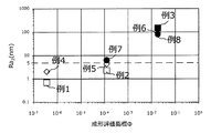
例1〜8の移動体用ガラス板をそれぞれ1枚ずつ製造し、各移動体用ガラス板の第1の主面(成形面に接触しない面)における2箇所のRa1、Wa1、Rc1、Rsm1を測定し、その平均値を求めた。また、第2の主面(成形面に接触する面)における2箇所のRa2、Wa2、Rc2、Rsm2の平均値を求めた。さらに、Ra2の平均値からRa1の平均値を減じた値をΔRaとして求めた。これらの結果を以下の表1に示す。
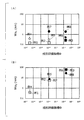
また、成形評価指標ΦとRa2の平均値との関係を図4に、成形評価指標ΦとΔRaとの関係を図5に、成形評価指標ΦとWaの平均値との関係を図6に、成形評価指標ΦとRcの平均値との関係を図7に、成形評価指標ΦとRsmの平均値との関係を図8に、それぞれ示す。〔evaluation〕
One glass plate for the moving body of Examples 1 to 8 is manufactured, and two Ra 1 , Wa 1 , and Rc 1 on the first main surface (the surface that does not contact the molding surface) of each glass plate for the moving body. , Rsm 1 was measured, and the average value thereof was obtained. In addition, the average values of Ra 2 , Wa 2 , Rc 2 , and Rsm 2 at two locations on the second main surface (the surface in contact with the molding surface) were obtained. Further, the value obtained by subtracting the average value of Ra 1 from the average value of Ra 2 was obtained as ΔRa. These results are shown in Table 1 below.
Further, the relationship between the molding evaluation index Φ and the average value of Ra 2 is shown in FIG. 4, the relationship between the molding evaluation index Φ and ΔRa is shown in FIG. 5, and the relationship between the molding evaluation index Φ and the average value of Wa is shown in FIG. The relationship between the molding evaluation index Φ and the average value of Rc is shown in FIG. 7, and the relationship between the molding evaluation index Φ and the average value of Rsm is shown in FIG. 8, respectively.
表1および図4に示すように、移動体用ガラス板の板厚にかかわらず、成形評価指標Φが大きいほどRa2が大きくなることが確認できた。特に、成形評価指標Φが1.82×10⁻²の場合、3種類全ての板厚(例3,6,8)においてRa2が5nm超となった。一方、成形評価指標Φが3.54×10⁻⁷の場合、2種類全ての板厚(例1,4)においてRa2が5nm以下となった。また、成形評価指標Φが1.23×10⁻⁴の場合、板厚が0.56mm(例7)のときにはRa2が5nm超であったが、2.0mm(例2)および1.1mm(例5)のときには5nm以下となった。
また、表1および図5に示すように、ΔRaは、例2,3,5〜8において、0.5nm超となり式(1)を満たし、例1及び4において、0.5nm以下となり式(1)を満たさないことがわかった。As shown in Table 1 and FIG. 4, it was confirmed that Ra 2 increases as the molding evaluation index Φ increases, regardless of the plate thickness of the moving glass plate. In particular, if the bending evaluation index Φ is 1.82 × 10 -2, Ra 2 becomes 5nm than in all three plate thickness (e.g. 3, 6, 8). On the other hand, when the molding evaluation index Φ was 3.54 × 10⁻⁷ , Ra 2 was 5 nm or less in all two types of plate thicknesses (Examples 1 and 4). When the molding evaluation index Φ was 1.23 × 10 -4 , Ra 2 was more than 5 nm when the plate thickness was 0.56 mm (Example 7), but 2.0 mm (Example 2) and 1.1 mm. In the case of (Example 5), it was 5 nm or less.
Further, as shown in Table 1 and FIG. 5, ΔRa becomes more than 0.5 nm in Examples 2, 3, 5 to 8 and satisfies the formula (1), and in Examples 1 and 4, it becomes 0.5 nm or less and the formula ( It was found that 1) was not satisfied.
例1〜8について、評価液体としてグリセリンを使用し、濡れ性を確認した。濡れ性については、例1〜8の第2の主面にグリセリンを滴下し、その接触角を求め、これにより濡れ性を判断した。接触角の測定には、ポータブル接触角計(協和界面科学株式会社、PCA−1)を使用し、グリセリンの滴下量は2〜3μLとした。測定は8回実施し、得られた測定値の平均を表2に示す。なお、測定箇所は、成形に使用した雌モールドの成形面に接触した第2の主面のうち、平坦な箇所を選び、測定した。 For Examples 1 to 8, glycerin was used as the evaluation liquid, and the wettability was confirmed. Regarding the wettability, glycerin was dropped on the second main surface of Examples 1 to 8 and the contact angle thereof was determined, thereby determining the wettability. A portable contact angle meter (Kyowa Interface Science Co., Ltd., PCA-1) was used to measure the contact angle, and the amount of glycerin dropped was 2 to 3 μL. The measurement was performed 8 times, and the average of the obtained measured values is shown in Table 2. As the measurement point, a flat point was selected from the second main surface in contact with the molding surface of the female mold used for molding, and the measurement was performed.
例1、2、4においては第2の主面のグリセリンの接触角が高い値となった。一方、例3、5〜8においては第2の主面のグリセリンの接触角が低く、第2の主面の濡れ性が良好であった。このことから、グリセリンのように高い粘性を有する接着剤を塗布する場合に、塗布性が向上し、最終製品の支持部材に確実に固定できることが期待できる。 In Examples 1, 2 and 4, the contact angle of the glycerin on the second main surface was high. On the other hand, in Examples 3, 5 to 8, the contact angle of the glycerin on the second main surface was low, and the wettability of the second main surface was good. From this, it can be expected that when an adhesive having a high viscosity such as glycerin is applied, the applicability is improved and the adhesive can be reliably fixed to the support member of the final product.
また、第1の主面に銀を薄く蒸着して半透過反射層を形成し、第2の主面側から光線を透過させる試験を行った。Ra2が5nm超であると、光線が適度に散乱され、視認者の視界を妨げるようなことはなかった。一方、Ra2が5nm以下であると、第2主面側から透過させた光線が直接的に視認者の視界に入り、視認性を妨げる結果となった。
さらに第1の主面に銀を薄く蒸着して半透過反射層を形成した移動体用ガラス板に像を投影したところ、例3、6〜8において第1の主面の表面粗さRa1が5nm以下で、第2の主面の表面粗さRa2が5nm超であるため、像が二重となることなく鮮明に視認できた。Further, a test was conducted in which silver was thinly vapor-deposited on the first main surface to form a semi-transmissive reflective layer, and light rays were transmitted from the second main surface side. When Ra 2 was more than 5 nm, the light rays were appropriately scattered and did not obstruct the visual field of the viewer. On the other hand, when Ra 2 is 5 nm or less, the light rays transmitted from the second main surface side directly enter the visual field of the viewer, which hinders the visibility.
Further, when an image was projected onto a moving glass plate on which silver was thinly vapor-deposited on the first main surface to form a semi-transmissive reflective layer, the surface roughness Ra 1 of the first main surface was shown in Examples 3, 6 to 8. Is 5 nm or less, and the surface roughness Ra 2 of the second main surface is more than 5 nm, so that the image can be clearly seen without duplication.
例3、6および8は、虚像のうねりがなく、外観も全く歪んでなかった。これは表1および図6に示すように、Wa1が10nm以下となり、Wa2が10nm超となったためと考えられる。In Examples 3, 6 and 8, there was no virtual image swell and the appearance was not distorted at all. It is considered that this is because Wa 1 is 10 nm or less and Wa 2 is more than 10 nm as shown in Table 1 and FIG.
例3および例6〜8は、虚像のうねりがなく、かつグリセリン滴下時に、空気を噛みこみにくく良好な接着性が期待される。これは表1および図7に示すように、Rc1が10nm以下となり、Rc2が27nm超となったためと考えられる。In Examples 3 and 6 to 8, there is no waviness of the virtual image, and when glycerin is dropped, it is difficult for air to be caught and good adhesiveness is expected. It is considered that this is because Rc 1 is 10 nm or less and Rc 2 is more than 27 nm as shown in Table 1 and FIG.
例3、6および8は、ガラスの優れた質感を維持しつつ、優れたギラツキ特性と防眩性といった光学特性を有していた。これは表1および図8に示すように、Rsm1が11nm以下となり、Rsm2が28nm超となったためと考えられる。Examples 3, 6 and 8 had optical properties such as excellent glare and anti-glare properties while maintaining the excellent texture of glass. It is considered that this is because Rsm 1 is 11 nm or less and Rsm 2 is more than 28 nm as shown in Table 1 and FIG.
以上のことから、Ra2が5nmを超えかつΔRaが0.5nmを超えるように、第1の主面の粗さを抑え、第2の主面が粗くなるように条件を制御することで、接着面の接着性向上と非接着面の光学品質の向上という両方の効果を両立したガラス板が得られる。From the above, the roughness of the first main surface is suppressed so that Ra 2 exceeds 5 nm and ΔRa exceeds 0.5 nm, and the conditions are controlled so that the second main surface becomes rough. A glass plate having both effects of improving the adhesiveness of the bonded surface and improving the optical quality of the non-bonded surface can be obtained.
本発明を詳細に、また特定の実施態様を参照して説明したが、本発明の精神と範囲を逸脱することなく、様々な修正や変更を加えることができることは、当業者にとって明らかである。
本出願は、2017年3月23日出願の日本特許出願2017−058205に基づくものであり、その内容はここに参照として取り込まれる。Although the present invention has been described in detail and with reference to specific embodiments, it will be apparent to those skilled in the art that various modifications and modifications can be made without departing from the spirit and scope of the invention.
This application is based on Japanese Patent Application No. 2017-058205 filed on March 23, 2017, the contents of which are incorporated herein by reference.
1A,1B…HUD装置、2A…反射鏡、3B…コンバイナ、10…移動体用ガラス板、11…第1の主面、12…第2の主面、20…反射層、91A,91B…投射手段、95A…接着層、96A…支持部材、D…利用者、L1,L2…像形成光、V1,V2…虚像(像)、WS…風防ガラス 1A, 1B ... HUD device, 2A ... reflector, 3B ... combiner, 10 ... glass plate for moving body, 11 ... first main surface, 12 ... second main surface, 20 ... reflective layer, 91A, 91B ... projection Means, 95A ... adhesive layer, 96A ... support member, D ... user, L1, L2 ... image forming light, V1, V2 ... virtual image (image), WS ... windshield
Claims (15)
前記移動体用ガラス板は、コンバイナ、反射鏡、クラスター、CID及び車載用表示装置用カバーガラスからなる群より選ばれる1に用いられ、
第1の主面の算術平均粗さRa1(nm)と第2の主面の算術平均粗さRa2(nm)とが、以下の式(1)を満たし、前記Ra1が5nm以下であり、前記Ra2が5nm超であることを特徴とする移動体用ガラス板。
Ra2−Ra1>0.5nm …(1) A glass plate for a moving body having a bent portion and provided on the moving body.
The moving glass plate is used in 1 selected from the group consisting of a combiner, a reflector, a cluster, a CID, and a cover glass for an in-vehicle display device.
The arithmetic average roughness Ra 1 (nm) of the first main surface and the arithmetic average roughness Ra 2 (nm) of the second main surface satisfy the following formula (1), and the Ra 1 is 5 nm or less. A glass plate for a moving body, characterized in that Ra 2 is more than 5 nm.
Ra 2- Ra 1 > 0.5 nm ... (1)
前記移動体用ガラス板は、前記反射鏡として用いられ、前記第1の主面で前記像形成光
を反射し、前記第2の主面が接着層を介して支持部材に固定される請求項13に記載の表示装置。 The display device is a head-up display that reflects the image-forming light projected by the projection means with a reflecting mirror and projects it onto the windshield of the moving body, and displays it as a virtual image on the opposite side of the user sandwiching the windshield. It is a device
A claim that the moving glass plate is used as the reflecting mirror, reflects the image-forming light on the first main surface, and the second main surface is fixed to a support member via an adhesive layer. The display device according to 13.
前記移動体用ガラス板は、前記コンバイナとして用いられ、前記第1の主面に前記像形成光が投影されるとともに、前記第1の主面および前記第2の主面を介して前記移動体の外部を視認可能に設けられる請求項13に記載の表示装置。 The display device is a head-up display device that projects the image-forming light projected by the projection means onto a combiner and displays it as a virtual image on the opposite side of the user across the combiner.
The moving glass plate is used as the combiner, and the image-forming light is projected onto the first main surface, and the moving body is projected through the first main surface and the second main surface. The display device according to claim 13, which is provided so that the outside of the screen can be visually recognized.
Applications Claiming Priority (3)
| Application Number | Priority Date | Filing Date | Title |
|---|---|---|---|
| JP2017058205 | 2017-03-23 | ||
| JP2017058205 | 2017-03-23 | ||
| PCT/JP2018/010913 WO2018174033A1 (en) | 2017-03-23 | 2018-03-19 | Glass plate for moving bodies and display device |
Publications (2)
| Publication Number | Publication Date |
|---|---|
| JPWO2018174033A1 JPWO2018174033A1 (en) | 2020-05-14 |
| JP6973473B2 true JP6973473B2 (en) | 2021-12-01 |
Family
ID=63584404
Family Applications (1)
| Application Number | Title | Priority Date | Filing Date |
|---|---|---|---|
| JP2019507674A Active JP6973473B2 (en) | 2017-03-23 | 2018-03-19 | Glass plate and display device for mobile objects |
Country Status (4)
| Country | Link |
|---|---|
| EP (1) | EP3604241B1 (en) |
| JP (1) | JP6973473B2 (en) |
| CN (1) | CN110461782A (en) |
| WO (1) | WO2018174033A1 (en) |
Families Citing this family (5)
| Publication number | Priority date | Publication date | Assignee | Title |
|---|---|---|---|---|
| KR20210086709A (en) * | 2018-11-27 | 2021-07-08 | 코닝 인코포레이티드 | Head-up display mirror with improved surface and edge quality and method of forming same |
| US20220011572A1 (en) * | 2018-11-29 | 2022-01-13 | Corning Incorporated | Aspheric mirror with reverse curvature for head-up display system and methods for forming the same |
| WO2022071374A1 (en) * | 2020-10-02 | 2022-04-07 | 日本精機株式会社 | Mirror and head-up display device |
| CN112373407A (en) * | 2020-11-23 | 2021-02-19 | 穆国华 | Automobile windshield display screen and system thereof |
| FR3117070A1 (en) * | 2020-12-08 | 2022-06-10 | Eyelights | Vehicle control panel and associated vehicle |
Family Cites Families (11)
| Publication number | Priority date | Publication date | Assignee | Title |
|---|---|---|---|---|
| JP2004131347A (en) | 2002-10-11 | 2004-04-30 | Asahi Glass Co Ltd | Method of bending glass plate |
| JP2005170766A (en) | 2003-12-15 | 2005-06-30 | Asahi Glass Co Ltd | Method and apparatus of bending glass plate |
| JP4781319B2 (en) * | 2007-06-21 | 2011-09-28 | 恵和株式会社 | Optical sheet, optical sheet manufacturing method, and backlight unit |
| JP2009269762A (en) * | 2008-04-30 | 2009-11-19 | Fuji Electric Device Technology Co Ltd | Glass raw material, molding die for the same, and method for manufacturing glass substrate for magnetic disk |
| KR101452882B1 (en) * | 2009-07-08 | 2014-10-22 | 니폰 덴키 가라스 가부시키가이샤 | Glass plate |
| JP2011138589A (en) * | 2009-12-29 | 2011-07-14 | Hoya Corp | Method for manufacturing glass substrate for magnetic disk and magnetic recording medium |
| CN105793203B (en) * | 2013-02-20 | 2022-03-01 | 康宁股份有限公司 | Method and apparatus for forming shaped glass articles |
| EP2994432B1 (en) * | 2013-05-07 | 2020-07-22 | Corning Incorporated | Process and apparatus for forming shaped glass articles |
| JP6394110B2 (en) * | 2013-07-08 | 2018-09-26 | 日本電気硝子株式会社 | Method for producing tempered glass |
| JP6086954B2 (en) * | 2014-08-08 | 2017-03-01 | Japan 3D Devices株式会社 | Optical bent glass plate and method for producing the same |
| JP6582780B2 (en) | 2015-09-15 | 2019-10-02 | オムロン株式会社 | Probe pin and inspection jig using the same |
-
2018
- 2018-03-19 WO PCT/JP2018/010913 patent/WO2018174033A1/en unknown
- 2018-03-19 EP EP18771298.9A patent/EP3604241B1/en active Active
- 2018-03-19 CN CN201880020319.7A patent/CN110461782A/en active Pending
- 2018-03-19 JP JP2019507674A patent/JP6973473B2/en active Active
Also Published As
| Publication number | Publication date |
|---|---|
| EP3604241B1 (en) | 2022-11-09 |
| EP3604241A1 (en) | 2020-02-05 |
| CN110461782A (en) | 2019-11-15 |
| JPWO2018174033A1 (en) | 2020-05-14 |
| EP3604241A4 (en) | 2021-01-13 |
| WO2018174033A1 (en) | 2018-09-27 |
Similar Documents
| Publication | Publication Date | Title |
|---|---|---|
| JP6973473B2 (en) | Glass plate and display device for mobile objects | |
| JP6687044B2 (en) | Curved cover glass, manufacturing method thereof, and in-vehicle display member | |
| JP6909162B2 (en) | Laminated structures including light guide plates and automotive glazing | |
| TWI810223B (en) | Aspheric mirror for head-up display system and methods for forming the same | |
| TWI652164B (en) | Glass-layered structure of the head-up display system | |
| TWI772569B (en) | Systems and methods for vacuum-forming aspheric mirrors | |
| TWI789463B (en) | Vacuum mold apparatus, systems, and methods for forming curved mirrors | |
| JP2022511740A (en) | Head-up display mirrors with improved surface and edge quality, and their molding methods | |
| WO2022244873A1 (en) | Laminated glass, and head-up display system | |
| CN113260900B (en) | Aspherical mirror with inverse curvature for head-up display system and method of forming the same | |
| TWI839412B (en) | Head-up display mirror with improved surface and edge quality and methods for forming the same |
Legal Events
| Date | Code | Title | Description |
|---|---|---|---|
| A621 | Written request for application examination |
Free format text: JAPANESE INTERMEDIATE CODE: A621 Effective date: 20200826 |
|
| A131 | Notification of reasons for refusal |
Free format text: JAPANESE INTERMEDIATE CODE: A131 Effective date: 20210727 |
|
| A521 | Request for written amendment filed |
Free format text: JAPANESE INTERMEDIATE CODE: A523 Effective date: 20210917 |
|
| TRDD | Decision of grant or rejection written | ||
| A01 | Written decision to grant a patent or to grant a registration (utility model) |
Free format text: JAPANESE INTERMEDIATE CODE: A01 Effective date: 20211005 |
|
| A61 | First payment of annual fees (during grant procedure) |
Free format text: JAPANESE INTERMEDIATE CODE: A61 Effective date: 20211018 |
|
| R150 | Certificate of patent or registration of utility model |
Ref document number: 6973473 Country of ref document: JP Free format text: JAPANESE INTERMEDIATE CODE: R150 |