JP6972473B2 - A method for manufacturing a bladed disc for a radial turbomachinery and a bladed disc obtained by this method. - Google Patents
A method for manufacturing a bladed disc for a radial turbomachinery and a bladed disc obtained by this method. Download PDFInfo
- Publication number
- JP6972473B2 JP6972473B2 JP2018550796A JP2018550796A JP6972473B2 JP 6972473 B2 JP6972473 B2 JP 6972473B2 JP 2018550796 A JP2018550796 A JP 2018550796A JP 2018550796 A JP2018550796 A JP 2018550796A JP 6972473 B2 JP6972473 B2 JP 6972473B2
- Authority
- JP
- Japan
- Prior art keywords
- blades
- blade
- auxiliary
- disc
- annular
- Prior art date
- Legal status (The legal status is an assumption and is not a legal conclusion. Google has not performed a legal analysis and makes no representation as to the accuracy of the status listed.)
- Active
Links
Images


Classifications
-
- F—MECHANICAL ENGINEERING; LIGHTING; HEATING; WEAPONS; BLASTING
- F01—MACHINES OR ENGINES IN GENERAL; ENGINE PLANTS IN GENERAL; STEAM ENGINES
- F01D—NON-POSITIVE DISPLACEMENT MACHINES OR ENGINES, e.g. STEAM TURBINES
- F01D5/00—Blades; Blade-carrying members; Heating, heat-insulating, cooling or antivibration means on the blades or the members
- F01D5/02—Blade-carrying members, e.g. rotors
- F01D5/04—Blade-carrying members, e.g. rotors for radial-flow machines or engines
- F01D5/041—Blade-carrying members, e.g. rotors for radial-flow machines or engines of the Ljungström type
-
- B—PERFORMING OPERATIONS; TRANSPORTING
- B23—MACHINE TOOLS; METAL-WORKING NOT OTHERWISE PROVIDED FOR
- B23P—METAL-WORKING NOT OTHERWISE PROVIDED FOR; COMBINED OPERATIONS; UNIVERSAL MACHINE TOOLS
- B23P15/00—Making specific metal objects by operations not covered by a single other subclass or a group in this subclass
- B23P15/006—Making specific metal objects by operations not covered by a single other subclass or a group in this subclass turbine wheels
-
- F—MECHANICAL ENGINEERING; LIGHTING; HEATING; WEAPONS; BLASTING
- F01—MACHINES OR ENGINES IN GENERAL; ENGINE PLANTS IN GENERAL; STEAM ENGINES
- F01D—NON-POSITIVE DISPLACEMENT MACHINES OR ENGINES, e.g. STEAM TURBINES
- F01D5/00—Blades; Blade-carrying members; Heating, heat-insulating, cooling or antivibration means on the blades or the members
- F01D5/12—Blades
- F01D5/22—Blade-to-blade connections, e.g. for damping vibrations
- F01D5/225—Blade-to-blade connections, e.g. for damping vibrations by shrouding
-
- F—MECHANICAL ENGINEERING; LIGHTING; HEATING; WEAPONS; BLASTING
- F05—INDEXING SCHEMES RELATING TO ENGINES OR PUMPS IN VARIOUS SUBCLASSES OF CLASSES F01-F04
- F05D—INDEXING SCHEME FOR ASPECTS RELATING TO NON-POSITIVE-DISPLACEMENT MACHINES OR ENGINES, GAS-TURBINES OR JET-PROPULSION PLANTS
- F05D2230/00—Manufacture
- F05D2230/10—Manufacture by removing material
Landscapes
- Engineering & Computer Science (AREA)
- Mechanical Engineering (AREA)
- General Engineering & Computer Science (AREA)
- Structures Of Non-Positive Displacement Pumps (AREA)
Description
本発明の目的は、ラジアルターボ機械用羽根付きディスクの製造方法およびこの方法によって得られる羽根付きディスクである。 An object of the present invention is a method for manufacturing a bladed disc for a radial turbomachine and a bladed disc obtained by this method.
ラジアルターボ機械は、それがエネルギを交換する流体の流れが、同一ターボ機械内で終わる少なくとも一部の通路に対して径方向に向けられるターボ機械が意図されている。通路の、この径方向部分は、少なくとも一つの環状のセット羽根によって区切られ、これを通って、流体は、ターボ機械の回転軸に対して径方向に優勢に移動する。 Radial turbomachinery is intended for turbomachinery in which the flow of fluid with which it exchanges energy is directed radially with respect to at least some passages ending within the same turbomachinery. This radial portion of the passage is separated by at least one annular set vane through which the fluid moves radially predominantly with respect to the axis of rotation of the turbomachine.
「羽根付きディスク」は、ディスクの前面に留められた複数の環状のセット羽根を備える。これらのセットは、同心であり、各セットは、ディスクの中心軸から等距離に配置された複数の羽根を備える。 A "bladed disc" comprises a plurality of annular set blades fastened to the front of the disc. These sets are concentric and each set comprises a plurality of blades equidistant from the central axis of the disc.
複数の羽根は、前面から離れて延び、これらの羽根の前縁部および後縁部は、中心軸に対して平行または実質的に平行である。 The blades extend away from the anterior surface, and the leading and trailing edges of these blades are parallel or substantially parallel to the central axis.
羽根付きディスクは、複数の補強リングを更に備え、各補強リングは、前記羽根の一端で環状のセットの羽根の全てと連結され、その端部は、ディスクの前面に連結される端部の反対側にある。 The bladed disc further comprises a plurality of reinforcing rings, each reinforcing ring connected to all of the blades of the annular set at one end of the blade, the end of which is the opposite of the end connected to the front of the disc. On the side.
羽根付きディスクは、(ステータプレートとも呼ばれ、ターボ機械のケーシングに対して固定され、その羽根はステータ羽根である)ステータの機能および(ロータディスクと呼ばれ、ターボ機械のシャフトと共に回転し、その羽根はロータ羽根であり、したがって、中心軸は回転軸である)ロータの機能を有する。
Vaned disc (also called stator plate, fixed relative to the turbomachine casing, the blades are stator blades) are called function and (rotor disk of the stator, and rotating together with the turbomachine shaft, Its blades are rotor blades, so the central axis is the axis of rotation) has the function of a rotor.
本発明は、遠心力利用のラジアル(アウトフロー型)ターボ機械および求心力利用の(インフロー型)ターボ機械の両方に適用される。本発明は、駆動型ターボ機械(タービン)および作動型機械(圧縮機)の両方に適用される。好ましくは、本発明は膨張型タービンに関するが、これに限定されるものではない。好ましくは、本発明は、電気エネルギおよび/または機械エネルギを生み出す為の膨張タービンに関するが、これに限定されるものではない。本発明は、好ましくは、水蒸気を使用するランキンサイクルによって、又は有機ランキンサイクル(ORC)によって、地熱資源を使用する発電所に利用される膨張タービンに関するのが好ましいが、これに限定されるものではない。 The present invention applies to both centrifugal (outflow type) turbomachinery utilizing centrifugal force and (inflow type) turbomachinery utilizing centripetal force. The present invention applies to both driven turbomachinery (turbines) and actuated machines (compressors). Preferably, the invention relates to, but is not limited to, an expansion turbine. Preferably, the invention relates to, but is not limited to, an expansion turbine for producing electrical and / or mechanical energy. The present invention preferably relates to an expansion turbine utilized in a power plant using geothermal resources, preferably by a Rankine cycle using steam or by an organic Rankine cycle (ORC), but is not limited thereto. No.
公報US 4,306,833は、周辺領域に配置された2つの環状のセットの羽根を有するディスクであって、各々がディスクの両面の一つにあるディスクが装備された羽根車を備えた圧縮機を図示する。各セットの羽根は、それぞれの環状チャンバ内に延びる。羽根付きディスクは、ダイカストによって実現可能である。リングは、セットの羽根の各先端に付けられ、前記先端の渦形成による損失を排除する。各リングは、羽根車に設けられたボスに挿入されるネジによって羽根車に固定される。 Publication US 4,306,833 illustrates a compressor with impellers equipped with discs, each with a disc on one of both sides of the disc, with a disc having two sets of annular blades located in the peripheral area. .. The blades of each set extend into their respective annular chambers. The bladed disc can be realized by die casting. A ring is attached to each tip of the blade of the set to eliminate the loss due to vortex formation at the tip. Each ring is fixed to the impeller by a screw inserted into a boss provided on the impeller.
公報US 6,508,631は、ラジアルフロー型ポンプを図示する。このポンプは、ロータと、同心リングに配置され、回転の中心軸に対して実質的に平行な方向にロータの第1面から延びる複数の羽根とを備える。ロータおよび複数の羽根は、単体材料から一体的に形成される。遠心力による変形を減少させる支持リングは、羽根の周りに位置される。 Publication US 6,508,631 illustrates a radial flow pump. The pump comprises a rotor and a plurality of blades arranged in a concentric ring and extending from a first surface of the rotor in a direction substantially parallel to the central axis of rotation. The rotor and the plurality of blades are integrally formed from a single material. Support rings that reduce centrifugal force deformation are located around the blades.
この範囲で、出願人は、その生産を加速させ、関連費用を削減しつつ、それらが組み込まれるターボ機械の信頼性及び効率を補償するような高品質を確実にするように、ラジアルターボ機械用羽根付きディスクの為に従来技術の製造方法を改良する必要性に気づいた。 To this extent, Applicants are for radial turbomachinery to accelerate their production, reduce associated costs, and ensure high quality that compensates for the reliability and efficiency of the turbomachinery in which they are incorporated. I realized the need to improve the manufacturing method of the prior art for the bladed disc.
実際、出願人が留意したことは、文献US 4,306,833に図示されたダイカストによるディスクの生産が、たとえば、発電所において、エネルギ発生の為の高精度(即ち、要求される高効率レベルの)ジオメトリを有する羽根を得ることを可能にしないことである。さらに、その文献で開示された圧縮機は、羽根車のディスクの二面に分割された一段のみを有し、それは、エンタルピ上昇を管理するには適していない。最後に、US 4,306,833に開示されたボスは、ロータディスクのリングを装着することを可能にするが、これは、2つの隣接した羽根の間に置かれているので、これらは、これらを通って流れる作動流体の流れを妨害する。 In fact, the applicant noted that the die-cast disk production illustrated in reference US 4,306,833, for example, in a power plant, provides a highly accurate (ie, required high efficiency level) geometry for energy generation. It is not possible to obtain the blades it has. Moreover, the compressor disclosed in that document has only one stage divided into two sides of the impeller disk, which is not suitable for managing enthalpy rise. Finally, the boss disclosed in US 4,306,833 allows the ring of the rotor disc to be fitted, but since it is placed between two adjacent blades, these pass through them. Obstructs the flow of working fluid.
同様に出願人が気づいたことは、文献US 6,508,631に開示されたロータが補強リングを持たないこと、そのため、漏れによる損失を減少させて所望の収率を得ることを可能にしないことである。さらに、これらの文献のいずれも、それぞれのロータを生産する為の方法を詳細に図示していない。 Similarly, the applicant has noticed that the rotor disclosed in Ref. US 6,508,631 does not have a reinforcing ring, and thus does not allow the loss due to leakage to be reduced to obtain the desired yield. Moreover, neither of these documents illustrates in detail the method for producing each rotor.
この範囲において、出願人は、以下の目的を設定した。 To this extent, the applicant has set the following objectives:
「製造費用を減らす為に、羽根付きディスクの製造の為に迅速かつ比較的に簡単な方法を提供すること」 "Providing a quick and relatively easy way to manufacture bladed discs to reduce manufacturing costs."
「いずれの場合においても、その品質及び構造的精度を改善することを可能し、ラジアルターボ機械が組み込まれるラジアルターボ機械の信頼性及び効率を改善することを可能にする、羽根付きディスクの製造の為の方法を提供すること」 "In any case, the manufacture of bladed discs, which makes it possible to improve its quality and structural accuracy and improve the reliability and efficiency of the radial turbomachinery in which the radial turbomachinery is incorporated. To provide a way for
出願人が見い出したことは、上記及び他の目的が、固体材料から羽根を実現することによって、すなわち、初期の単体から材料を除去することによって達成可能であり、羽根は、ディスク上に、及び/又は一つ又は複数の補強リング上の固定材料から形成されることである。 What the applicant has found is that the above and other objectives can be achieved by realizing the blades from a solid material, i.e. by removing the material from the initial simple substance, the blades on the disc, and. / Or to be formed from a fixing material on one or more reinforcing rings.
特に、上記及び他の目的は、ラジアルターボ機械用羽根付きディスクの製造の為の方法によって、一つ又は複数の添付された特許請求の範囲に従う、さらに/または、一つ又は複数の以下の態様に従うラジアルターボ機械によって実質的に達成される。 In particular, the above and other purposes are in accordance with one or more of the attached claims, and / or one or more of the following embodiments, by method for the manufacture of bladed discs for radial turbomachinery. Achieved substantially by radial turbomachinery according to.
本願の説明において、更に、添付された特許請求の範囲において、用語「軸方向」は、羽根付きディスクの中心軸またはターボ機械の回転軸「X−X」に対して平行に向けられた方向を画定することが意図される。形容詞「径方向の」は、羽根付きディスクの中心軸またはターボ機械の回転軸「X−X」から垂直に延びる半径に向けられた方向を画定することが意図される。形容詞「周方向の」は、羽根付きディスクの中心軸またはターボ機械の回転軸「X−X」と同軸の円周に対して接する方向であることが意図される。 In the description of the present application, further, in the appended claims, the term "axial direction" refers to a direction oriented parallel to the central axis of the bladed disk or the rotation axis "XX" of the turbomachinery. Intended to demarcate. The adjective "diametrically" is intended to define a direction directed to a radius extending vertically from the central axis of the bladed disc or the rotation axis "XX" of the turbomachinery. The adjective "circumferential" is intended to be in contact with the central axis of the bladed disc or the circumferential axis coaxial with the turbomachinery rotation axis "XX".
より具体的には、独立形態に従って、本発明は、ラジアルターボ機械用羽根付きディスクの製造の為の方法に関する。 More specifically, according to an independent form, the present invention relates to a method for the manufacture of bladed discs for radial turbomachinery.
当該方法は、前面が設けられたディスクを準備するステップを含む。 The method involves preparing a disc with a front surface.
当該方法は、異なる直径を持つ複数の補強リングを準備するステップを含む。 The method involves preparing multiple reinforcing rings with different diameters.
ディスクを準備するステップは、前記ディスクと一体に環状のセット羽根を実現する工程を含み、これらのセット羽根は、前記ディスクの中心軸と同心かつ同軸であり、前記前面に配置され、各々の羽根は、前縁部と、前記中心軸に対して実質的に平行な後縁部とを有する。 The step of preparing the disc comprises the step of realizing an annular set blade integrally with the disc, the set blade being concentric and coaxial with the central axis of the disc, arranged in front of the disc, and each blade. Has a leading edge and a trailing edge substantially parallel to the central axis.
代替または追加で、複数の補強リングを準備するステップは、補強リングの中心軸の周りに配置された環状のセット補助羽根を、前記補強リングの各々と一体に実現する工程を含み、各々の補助羽根は、前縁部と、前記補強リングの前記中心軸に対して実質的に平行の後縁部とを有する。 The step of preparing multiple reinforcing rings, as an alternative or in addition, includes the step of realizing an annular set auxiliary blade arranged around the central axis of the reinforcing ring integrally with each of the reinforcing rings, and each auxiliary. The blade has a leading edge and a trailing edge substantially parallel to the central axis of the reinforcing ring.
当該方法は、前記環状のセット羽根及び/又は補助羽根の一つに向かってディスクに補強リングの各々を付けるステップを含み、前面に環状のセット羽根及び/又は補助羽根を画定し、各々には、それぞれの補強リングが設けられる。 The method comprises attaching each of the reinforcing rings to the disc towards one of the annular set blades and / or auxiliary blades, defining an annular set blade and / or auxiliary blades in front of each of the annular set blades and / or auxiliary blades. , Each reinforcement ring is provided.
換言すると、当該方法は、固体材料から全ての羽根をディスク上に実現するステップ、あるいは、固体からの全ての羽根を各補強リング上に実現するステップ、あるいは、幾つかの羽根をディスク上に他の羽根を一つ又は複数の補強リング上に実現するステップを含み、その後、完全な環状のセット羽根を形成するようにリングをディスクに接合するステップを含む。 In other words, the method implements all blades from a solid material on a disc, or all blades from a solid on each reinforcing ring, or some blades on a disc, etc. Includes the step of implementing the blades on one or more reinforcing rings, followed by joining the rings to the disc to form a fully annular set blade.
好ましくは、ディスクを準備するステップは、固体ディスクを準備する工程と、固体ディスクから材料を除去し、前面に複数の環状レリーフを画定する工程であって、複数の環状レリーフは、前記ディスクの中心軸と同心かつ同軸である、工程とを含む。 Preferably, the step of preparing the disc is a step of preparing the solid disc and a step of removing the material from the solid disc and defining a plurality of annular reliefs on the front surface, wherein the plurality of annular reliefs are in the center of the disc. Includes processes that are concentric and coaxial with the axis.
好ましくは、環状のセット羽根の一つが画定されるまで、環状レリーフの各々から材料が除去され、補強リングの各々がディスクの羽根の末端部に付けられることが、各々の環状レリーフに対して考えられる。 Preferably, it is considered for each annular relief that material is removed from each of the annular reliefs and each of the reinforcing rings is attached to the end of the blade of the disc until one of the annular set blades is defined. Be done.
一つの実施形態は、各々の環状レリーフに対して、根元リングと、根元リングから突出する列挙された環状のセット羽根が画定されるまで、各々の環状レリーフから材料を除去する工程を含む。 One embodiment comprises, for each annular relief, removing material from each annular relief until a root ring and an enumerated annular set blade projecting from the root ring are defined.
一実施形態は、羽根を持たない根元リングのみが画定されるまで、各々の環状レリーフから材料を除去する工程含む。 One embodiment comprises removing material from each annular relief until only the root ring without wings is defined.
好ましくは、各々の補強リングを準備するステップは、固体リングを準備する工程と、それぞれの環状のセット補助羽根が画定されるまで固体リングから材料を除去する工程と、を含む。 Preferably, the step of preparing each reinforcing ring comprises the step of preparing the solid ring and the step of removing the material from the solid ring until the respective annular set auxiliary vanes are defined.
一態様において、各々のセットに対して、羽根は、前記ディスクと一体で作られ、補助羽根は、それぞれの補強リングと一体で作られ、補強リングの各々を付けるステップは、環状のセットディスクの2つの羽根の間に各々の補助羽根を設置する工程と、補助羽根の末端部をディスクの前面に付ける工程とを含む。 In one embodiment, for each set, the blades are made integrally with the disc, the auxiliary blades are made integrally with the respective reinforcing rings, and the step of attaching each of the reinforcing rings is an annular set disc. It includes a step of installing each auxiliary blade between the two blades and a step of attaching the end portion of the auxiliary blade to the front surface of the disk.
追加の独立した態様によると、本発明は、ラジアルターボ機械用羽根付きディスクの製造方法に関し、その方法は、 According to an additional independent aspect, the present invention relates to a method of manufacturing a bladed disc for a radial turbomachine.
(i)固体ディスクを準備するステップと、 (I) Steps to prepare a solid disc and
(ii)固体ディスクを凸凹切断し、ディスクを画定する為に固体ディスクから材料を除去するステップであって、その前面に、前記ディスクの中心軸と同心かつ同軸の複数の環状レリーフが設けられる、ステップと、 (Ii) A step of cutting a solid disc unevenly and removing material from the solid disc to define the disc, wherein a plurality of annular reliefs concentric and coaxial with the central axis of the disc are provided on the front surface thereof. Steps and
(iii)各々の環状レリーフに対して、中心軸の周りに配置された環状のセット羽根が画定されるまで、各々の環状レリーフから材料を除去するステップであって、各々の羽根は、前縁部と、前記中心軸と実質的に平行の後縁部とを有する、ステップと、 (Iii) For each annular relief, a step of removing material from each annular relief until an annular set vane disposed around the central axis is defined, where each blade is a leading edge. A step and a step having a portion and a trailing edge portion substantially parallel to the central axis.
(iv)各々が環状のセット羽根の一つに対応した、異なる直径の複数の補強リングを準備するステップと、 (Iv) With the step of preparing multiple reinforcing rings of different diameters, each corresponding to one of the annular set blades.
(v)それぞれの環状のセット羽根の末端部に補強リングの各々を付けるステップと、を含む。 (V) Includes a step of attaching each of the reinforcing rings to the ends of each annular set vane.
前縁部および後縁部に言及する「前記中心軸に対して実質的に平行」の定義は、前縁部及び後縁部が、直線でも、曲線でも、他の方法で成形されてもよいことが意図され、それらは、中心軸に対して平行な方向に沿って延びることが意図されている。換言すると、前縁部が径方向内側に面する(遠心力利用のラジアルターボ機械)、又は、外側に面する(遠心力利用のラジアルターボ機械)、後縁部が外側に面する(遠心力利用のラジアルターボ機械)又は内側に面する(遠心力利用のターボ機械)。 The definition of "substantially parallel to the central axis" with reference to the leading and trailing edges is that the leading and trailing edges may be straight, curved, or otherwise molded. It is intended that they extend along a direction parallel to the central axis. In other words, the front edge faces radially inward (radial turbomachinery using centrifugal force) or outward (radial turbomachinery using centrifugal force), and the trailing edge faces outward (centrifugal force). Radial turbomachinery used) or facing inward (turbomachinery using centrifugal force).
出願人が確認したことは、本発明に従う方法が、羽根を担持することが意図されたディスクの面で、さらに/または、補助羽根を担持することが意図された補強リングの面で、極端な精度で比較的簡単に作動することを可能にすることである。実際、工具は、特別な制限を受けることなく、前記面上を移動可能であり、前方から作業ができる。このステップの間、羽根は正確に画定されるので、その形成は、容易であり、迅速かつ正確なプロセスである。 Applicants have confirmed that the method according to the invention is extreme in terms of the disc intended to carry the blades and / or in terms of the reinforcing ring intended to carry the auxiliary blades. It is to enable it to operate relatively easily with accuracy. In fact, the tool can move on the surface without any special restrictions and can work from the front. During this step, the blades are precisely defined, so their formation is an easy, rapid and accurate process.
好ましくは、初期の固体ディスクおよび/または初期の固定リングは、鍛造加工されるが、それは必然的なものではない。 Preferably, the initial solid disc and / or the initial fixing ring is forged, but it is not inevitable.
好ましくは、初期の固体ディスクは、その直径とその軸方向の長さの比が2を越える。 Preferably, early solid discs have a ratio of their diameter to their axial length greater than two.
好ましくは、環状レリーフを形成する為の固体ディスクの荒削り(ディスクの半仕上げのステップ)は、回転または穿孔によって実行されるが、これは必然的なものではない。各々の環状レリーフの大きさは、次のステップで画定される羽根を含むような大きさである。 Preferably, the roughing of the solid disc (semi-finishing step of the disc) to form the annular relief is performed by rotation or perforation, but this is not inevitable. The size of each annular relief is such that it includes the vanes defined in the next step.
好ましくは、羽根の高さ、すなわち、それらの軸方向の拡張部および中央の膨張平面に特徴的な、それらの他の幾何学的寸法の全ては、固体ディスクおよび/または複数の固体ディスクの荒削りのプロセスの間に画定される。 Preferably, all of their other geometric dimensions, characteristic of the height of the blades, i.e. their axial extensions and the central expansion plane, are rough cuts of solid discs and / or multiple solid discs. Defined during the process of.
好ましくは、当該方法は、羽根に補強リングを載せる為の支持面を画定するステップを含む。各々の支持面は、それぞれの環状レリーフの端面が位置する面である。この支持面は、中心軸に対して垂直な支持平面または先端が切られた円錐面でもよい。 Preferably, the method comprises defining a support surface for mounting the reinforcing ring on the blade. Each support surface is the surface on which the end face of each annular relief is located. The support surface may be a support plane perpendicular to the central axis or a conical surface with a cut tip.
一態様において、羽根および/または補助羽根を画定する為の材料の除去(羽根の仕上げステップ)は、フライス加工、好ましくは、前方フライス加工、好ましくは、ボールノーズエンドミルによって実行される。好ましくは、フライス加工の送り量は、約100mm/分〜約8000mm/分である。好ましくは、フライス加工の切断深さは、約0.005mm〜5mmである。好ましくは、フライス加工の接線速度は、約60m/分〜約200m/分である。好ましくは、フライス加工の回転速度は、約1000rmp〜約25000rpmである。好ましくは、羽根の高さとフライス加工の直径の比は、約15未満である。 In one aspect, the removal of the material for defining the blades and / or auxiliary blades (blade finishing step) is performed by milling, preferably forward milling, preferably a ball nose end mill. Preferably, the feed rate for milling is from about 100 mm / min to about 8000 mm / min. Preferably, the cutting depth for milling is about 0.005 mm to 5 mm. Preferably, the tangential velocity of milling is from about 60 m / min to about 200 m / min. Preferably, the rotation speed of milling is from about 1000 rpm to about 25,000 rpm. Preferably, the ratio of blade height to milled diameter is less than about 15.
一態様において、羽根を画定する為の材料の除去は、放電加工によって実行される。好ましくは、羽根および/または補助羽根の実現は、羽根に対して相補形状(又は、2つの隣接した羽根の間に含まれる大きさの形をとる)少なくとも一つの電極を、少なくとも一つの環状レリーフ、好ましくは、環状レリーフの端面に、更に/又は少なくとも固体リングに付けることを含む。好ましくは、前記少なくとも一つの電極は、2つの羽根の間、および/または2つの隣接した補助羽根の間に含まれる大きさの形をとる単一作動部分を有し、前記2つの羽根の間、および/または2つの補助羽根の間の材料を除去し、前記2つの羽根の間、および/または2つの補助羽根の間に通路を画定する。好ましくは、前記少なくとも一つの電極は、(櫛状形状を画定するように)互いに離間された複数の作動部分を有し、各々は、2つの隣接した羽根の間、および/または2つの隣接した補助羽根の間に含まれる大きさの形をとり、多くの隣接した羽根の間の材料を同時に、さらに/または隣接した補助羽根の間の材料を除去し、前記羽根および/または補助羽根の間に通路を画定する。好ましくは、前記少なくとも一つの電極は、中心軸に対して平行な方向に前進される。好ましくは、前記少なくとも一つの電極の送り量は、約10mm/分〜約100mm/分である。 In one embodiment, the removal of material for defining the blades is performed by electrical discharge machining. Preferably, the vane and / or auxiliary vane implementation has at least one electrode complementary to the vane (or in the form of a size contained between two adjacent vanes) and at least one annular relief. , Preferably, include attaching to the end face of the annular relief and / or at least to a solid ring. Preferably, the at least one electrode has a single actuating portion in the form contained between two blades and / or between two adjacent auxiliary blades, between the two blades. And / or the material between the two auxiliary blades is removed and a passage is defined between the two blades and / or between the two auxiliary blades. Preferably, the at least one electrode has a plurality of actuating portions separated from each other (so as to define a comb shape), each between two adjacent blades and / or two adjacent blades. It takes the form of the size contained between the auxiliary blades and simultaneously removes the material between many adjacent blades and / or the material between the adjacent auxiliary blades and between the blades and / or the auxiliary blades. Define a passage in. Preferably, the at least one electrode is advanced in a direction parallel to the central axis. Preferably, the feed rate of the at least one electrode is from about 10 mm / min to about 100 mm / min.
一態様において、羽根を画定する為の材料の除去は、最初にフライス加工によって、深さが許容されるまで材料を除去し、放電加工によって作業を完了することによって実行される。 In one embodiment, the removal of the material for defining the blades is performed by first removing the material by milling until the depth is acceptable and then completing the work by electrical discharge machining.
羽根仕上げステップの目標は、表面の品質(たとえば、粗さRaは0.02〜32)および精度(たとえば、+/−0.01mm〜+/−0.5mm)に細心の注意を払って、最小限の時間で最大限の材料を除去することである。このステップの結果は、それぞれの環状のセット羽根が開いた状態で(すなわち、羽根がディスクから片持ち梁のように突出した)ディスクが得られ、さらに/または、それぞれのセット補助羽根が開いた状態で(すなわち、補助羽根がそれぞれのリングから片持ち梁のように突出した)一つ又は複数の補強リングが得られることである。 The goal of the blade finishing step is to pay close attention to the surface quality (eg, roughness Ra is 0.02-32) and accuracy (eg, +/- 0.01 mm to +/- 0.5 mm). It is to remove the maximum amount of material in the minimum amount of time. The result of this step was a disc with each annular set blade open (ie, the blade protruding like a cantilever from the disc), and / or each set auxiliary blade opened. In the state (ie, auxiliary blades project like cantilever from each ring) one or more reinforcing rings are obtained.
一態様において、各々の環状レリーフの為に環状のセット羽根を画定する工程は、ディスクの前面に付けられた根元リングを成形することを含み、それぞれの環状のセット羽根は、前記根元リングから突出する。換言すると、荒削りによって先に画定された環状レリーフは、根元部分を有し、この根元部分は、前面に隣接し、羽根および遠位部分の形成中、実質的に機械加工されないが、この遠位部分は、機械加工され、それから前記羽根が得られる。根元部分は、根元リングを画定する。好ましくは、少なくとも一つの根元リングは、先端が切られた円錐面を画定するように成形され、そこから羽根が突出する。 In one embodiment, the step of defining an annular set blade for each annular relief comprises forming a root ring attached to the front surface of the disc, each annular set blade protruding from the root ring. do. In other words, the annular relief previously defined by roughing has a root portion, which is adjacent to the anterior surface and is substantially unmachined during the formation of the vanes and distal portion, but this distal portion. The portion is machined from which the blades are obtained. The root portion defines the root ring. Preferably, at least one root ring is shaped to define a truncated conical surface from which the blades project.
この先端が切られた円錐面は、作動流体用通路の広がり比または収束(フレアリング)を画定する面である。 This truncated conical surface is the surface that defines the spread ratio or convergence (flaring) of the working fluid passage.
そのため、羽根および根元リングは、ディスクと一体のようになっている。 Therefore, the blade and the root ring are integrated with the disc.
一態様において、補強リングを付けるステップは、前記末端部に設置された連結装置を介して、それぞれの環状のセット羽根の末端部に補強リングを接合および/または補助羽根の末端部をディスクに接合する工程を含む。好ましくは、前記連結装置は、ねじおよび/または釘および/またはブレイズ溶接および/またはジョイントを含む。 In one embodiment, the step of attaching the reinforcing ring joins the reinforcing ring to the ends of the respective annular set blades and / or joins the ends of the auxiliary blades to the disc via a coupling device installed at the ends. Including the process of Preferably, the coupling device includes screws and / or nails and / or blaze welds and / or joints.
補強リングを羽根に、更に/又は、補助羽根をディスクに接合する手段が、熱膨張による径方向の応力および/または(ディスクがロータディスクの場合)遠心力域からの径方向応力によって影響されることを防止するため、リングを羽根にピン留めすることが可能である。ピンは、全ての羽根に挿入可能であり、連結装置と交互に挿入されてもよい。 The means of joining the reinforcing ring to the vanes and / or the auxiliary vanes to the disc is affected by the radial stress due to thermal expansion and / or the radial stress from the centrifugal force region (if the disc is a rotor disc). To prevent this, it is possible to pin the ring to the blade. Pins can be inserted into all blades and may be inserted alternately with the coupling device.
一態様において、連結装置は、各羽根の末端部に挿入されるネジと、前記ネジの側面に設置される2つのピンとを備える。 In one aspect, the coupling device comprises a screw inserted into the end of each blade and two pins placed on the sides of the screw.
異なる態様において、連結装置は、羽根の末端部に挿入されるネジと、隣接した羽根の末端部に挿入されるピンとを備える。 In a different embodiment, the coupling device comprises a screw inserted at the end of the blade and a pin inserted at the end of the adjacent blade.
一態様において、複数の補強リングを準備するステップは、補強リングの中心軸の周りに配置される環状のセット補助羽根を、補強リングの各々と一体で実現する工程を含む。各々の補助羽根は、前縁部と、補強リングの前記中心軸に対して実質的に平行な後縁部とを有する。 In one aspect, the step of preparing a plurality of reinforcing rings comprises the step of realizing an annular set auxiliary blade arranged around the central axis of the reinforcing ring integrally with each of the reinforcing rings. Each auxiliary vane has a leading edge and a trailing edge substantially parallel to said central axis of the reinforcing ring.
一態様において、補強リングの各々を付けるステップは、環状のセットディスクの2つの羽根の間に各々の補助羽根を設置する工程と、ディスクの前面に補助羽根の末端部を付ける工程とを含む。 In one aspect, the step of attaching each of the reinforcing rings comprises installing each auxiliary blade between the two blades of the annular set disc and attaching the end of the auxiliary blade to the front surface of the disc.
換言すると、当該方法の変形例によると、セット羽根の半分はディスクから一体として得られ、同一セットの前記羽根(補助羽根)の他の半分は、それぞれの補強リングから得られる。ディスクと一体で得られた羽根は、仕上げられる羽根付きディスクのピッチの2倍のピッチで離間され、補強リングの補助羽根も同様に、仕上げられる羽根付きディスクのピッチの2倍のピッチで離間される。いったん補強リングがディスク上に装着されると、セット羽根は、交互の羽根のディスク及び補助羽根によって形成され、ピッチ(羽根および隣接した補助羽根の間の周方向の距離)は正しいピッチである。このように、各々の個々の部品の機械加工は、より簡単なプロセスであることが分かる。たとえば、ミルの大きさを大きくすることができるので、フライス加工だけで実現可能な羽根の高さを得ることができる。 In other words, according to a modification of the method, half of the set blades are obtained integrally from the disc and the other half of the blades (auxiliary blades) of the same set are obtained from the respective reinforcing rings. The blades obtained integrally with the disc are separated at twice the pitch of the finished bladed disc, and the auxiliary blades of the reinforcing ring are similarly separated at twice the pitch of the finished bladed disc. NS. Once the reinforcing ring is mounted on the disc, the set blades are formed by alternating blade discs and auxiliary blades, and the pitch (circumferential distance between the blades and adjacent auxiliary blades) is the correct pitch. Thus, it turns out that the machining of each individual part is a simpler process. For example, since the size of the mill can be increased, it is possible to obtain a blade height that can be realized only by milling.
好ましくは、補助羽根の末端部をディスクの前面に付けるステップは、前記末端部に設置される連結装置を介してディスクに補助羽根の末端部を接合する工程を含む。好ましくは、前記連結装置は、ネジおよび/または釘および/またはブレイズ溶接および/またはジョイントを含む。この場合も同様に、補強リングは、ディスクの羽根にピン留め可能なので、補強リングを接合する連結装置が、異なるレベルの熱膨張による径方向の応力および/または(羽根付きディスクがロータディスクの場合)遠心力域からの応力によって影響されることを防止するため、補強リングをディスクの羽根にピン留めすることが可能である。 Preferably, the step of attaching the end of the auxiliary blade to the front surface of the disc comprises joining the end of the auxiliary blade to the disc via a coupling device installed at the end. Preferably, the coupling device includes screws and / or nails and / or blaze welds and / or joints. Again, the stiffening ring can be pinned to the blades of the disc, so that the coupling device joining the stiffening ring has radial stresses and / or (if the bladed disc is a rotor disc) due to different levels of thermal expansion. ) Reinforcing rings can be pinned to the blades of the disc to prevent them from being affected by stress from the centrifugal force range.
一態様によると、本発明は、前述した方法に従って、さらに/または、添付される特許請求の範囲によって実現されるラジアルターボ機械用羽根付きディスクに関する。 According to one aspect, the invention relates to a bladed disc for a radial turbomachinery that is further / or realized by the appended claims according to the method described above.
一態様によると、本発明は、前述した方法に従って、さらに/または、添付される特許請求の範囲によって実現される少なくとも一つの羽根付きディスクを備えるラジアルターボ機械に関する。 According to one aspect, the invention relates to a radial turbomachinery comprising at least one bladed disc realized according to the method described above and / or by the appended claims.
一態様によると、羽根付きディスクは、ロータまたはロータディスクである。 According to one aspect, the bladed disc is a rotor or a rotor disc.
一態様において、羽根付きディスクはステータ又はステータプレートである。 In one embodiment, the bladed disc is a stator or stator plate.
一態様において、ラジアルターボ機械は、遠心力利用のラジアルタービンであり、たとえば、単一ロータディスク付き、あるいは、2つの二重反転ディスク付きのラジアルタービンである。 In one aspect, the radial turbomachinery is a centrifugal turbine utilizing centrifugal force, eg, a radial turbine with a single rotor disk or with two counter-rotating disks.
更なる特徴および利点は、本発明に従うラジアルターボ機械用羽根付きディスク、その製造方法の、好ましいが限定されない実施形態の、ラジアルターボ機械の詳細な説明から明らかになる。 Further features and advantages will be evident from the detailed description of the radial turbomachinery according to the present invention, of the bladed discs for radial turbomachinery, a preferred but not limited embodiment of the method of manufacturing thereof.
以下、添付図面を参照して、説明するが、これらは、近似的、すなわち、限定されない実施例を提供する目的のためにのみ提供される。
以前に列挙した図を参照すると、参照符合1によってラジアルターボ機械が全体的に表示されている。
With reference to the figures listed earlier, the radial turbomachinery is displayed as a whole by
図1に図示されたラジアルターボ機械1は、一つのロータ2を備えた遠心力利用のラジアル型膨張タービンである。たとえば、このタービン1は、ランキンサイクル形式、有機ORC(有機ランキンサイクル)の、エネルギを発生させる為の、エネルギ源として地熱資源を使用する発電所の分野で使用可能である。
The
タービン1は、固定ケーシング3を備え、固定ケーシング3内に、ロータ2が回転できるように収容される。このため、ロータ2は、しっかりとシャフト4に連結され、シャフト4は、(シャフト4およびロータ2の回転軸と一致する)中心軸「X−X」に沿って伸び、適した軸受5によって固定ケーシング3内で支持されている。ロータ2は、ロータディスク6を備え、このロータディスク6は、前述したシャフト4に直接連結され、前面7と、反対側の後面8が設けられている。前面7は、中心軸「X−X」と同心かつ同軸の複数の羽根付きロータリングを片持ち梁のように担持する。
The
固定ケーシング3は、前壁10と後壁11とを備え、前壁10は、ロータディスク6の前面7の前に置かれ、後壁11は、ロータディスク6の後面の前に置かれる。前壁10は、作動流体用軸方向入口を画定する開口を有する。この軸方向入口12は、中心軸「X−X」に置かれ、円形であり、軸「X−X」と同心になっている。固定ケーシング3は、通路ボリュート13も有し、これは、作動流体の為に、ロータ2の径方向外部の周辺位置に置かれ、固定ケーシング3からの出口(図示せず)と流体連通している。
The fixed
ロータディスク6の前に位置するステータプレート14は、前壁10の内面に置かれ、固定されている。ステータプレート14の後面15は、固定ケーシング3の前壁10に付けられ、ステータプレート14の前面16は、ロータディスク2の前面7に面する。
The
ステータプレート14の前面16は、中心軸「X−X」と同心かつ同軸の複数の羽根付きステータリング17を片持ち梁のように担持する。羽根付きステータリング17は、ロータディスク6に向かって固定ケーシング3の内側に延び、それらは、羽根付きロータリング9と径方向で交互になっており、作動流体用径方向膨張通路を画定するが、作動流体は、軸方向入口12を通って入り、径方向に膨張し、通路ボリュート13に入って前述した出口(図示せず)を通って出るまで、ロータディスク2の周辺に向かって移動する。
The
羽根付きロータディスク9および羽根付きステータリング17は、互いに、その中でも構造的に類似している。以下、ロータディスク6の構造およびロータディスク6の製造方法の実施例を説明する。ステータプレートの構造は、類似しており、同一の方法が前記ステータプレート14を実現する為に使用できる。一般的に、この方法は、ラジアルターボ機械用羽根付きディスク(ステータディスク、ロータディスク)を製造する為に使用される。
The
この方法を使用して実現されたロータディスク6の一部分は、図2に図示されている。図1及び図2に見られるように、ロータディスク6は、中心軸「X−X」と同心かつ同軸の(図2には3つだけが見られる)5つの根元リング18を備える。5つの根元リング18は、前面7上に延び、それらの間に4つの環状で同心の根元窪み19を区切るように、それらは互いに径方向に離間されている。5つの前記根元リング18は、ロータディスク6と一体に作られている。
A portion of the
根元リング18の各々は、環状のセットのロータ羽根20を担持し、これらのロータ羽根20は、中心軸「X−X」から等距離である。そのため、ロータディスク6は、中心軸「X−X」と同心かつ同軸の、複数の環状のセットのロータ羽根20を担持する。セットのロータ羽根20は、1ピッチで周方向に離間され、2つの隣接した羽根は、それらの間に作動流体の為の通路を区切っている。
Each of the root rings 18 carries an annular set of
各々のロータ羽根20は、根元リング18の端面から延びている。ロータ羽根20は、根元リング18の前記端面から、更に、ロータディスク6の前面7から離れて延び、その前縁部21及び後縁部22は、中心軸「X−X」に対して平行または実質的に平行になっている。図示されたタービン1が遠心力利用のラジアル型である場合、前縁部21は、中心軸「X−X」と径方向で面し、後縁部22は、径方向外側で面する。
Each
各々の環状のセットのロータ羽根20の末端部は、根元リング18の反対側にあるが、これらは、補強リング23によって互いに連結されている。そのため、図示されたロータディスク6は、5つの補強リング23を有し、これらは、中心軸「X−X」と同心かつ同軸になっている。
The ends of the
前述したように、ステータプレート14は、構造が類似している。特に、ステータプレート14は、4つの同心の羽根付きステータリング17を備える。各々の羽根付きステータリング17は、根元リング24,環状のセットのステータ羽根25、補強リング26を備える。
As mentioned above, the
各々の羽根付きステータリング17は、2つの羽根付きロータリング9の間に径方向に入れられ、それらに対して回転するように構成されている。羽根付きステータリング17の各補強リング26は、根元窪み19に設置されている。環状のセットのロータ羽根20は、環状のセットのステータ羽根25と径方向に交互になっており、作動流体用の前述した径方向膨張通路を区切っている。
Each
ロータディスク6を参照すると、その製造方法は、固体ディスク27から始まり、実際のディスク、根元リング18、ロータ羽根20を一体化することを含む。
Referring to the
特に、前記固体ディスク27(図3)は、鍛造プロセスによって最初に実現される固体ディスク27は、直径「D」、軸方向の長さ(あるいは、厚さ)「t」を有する。固体ディスク27は、好ましくはステンレス鋼、たとえば、AISI 410, AISI 420, AISI 630 (PH17-4)又はPH13-4で作られている。直径「D」は、仕上げられたロータディスク6の直径と実質的に等しい。厚さ「t」は、補強リング23を除く、径方向最外部羽根付きロータリング9の軸方向の長さに少なくとも等しい。たとえば、直径「D」と軸方向の長さ「t」の比は、約8に等しい。
In particular, the solid disk 27 (FIG. 3), which is first realized by the forging process, has a diameter "D" and an axial length (or thickness) "t". The
固体ディスク27は、たとえば、回転または穿孔によって荒削りされ、前面7から材料「M」(図4)を除去し、前記前面7に複数の環状レリーフ28を区切るが、これらの環状レリーフ28は、ディスクの中心軸「X−X」と同心かつ同軸になっている(図4,図5,図6)。図示された5つの環状レリーフ28は、各々が根元リング18および環状のセットのロータ羽根20を形成する。各環状レリーフ28の大きさは、根元リング18と、次のステップで区切られるロータ羽根20とを含むような大きさになっている。図4及び図5で気づけるように、このステップで形成される各々の環状レリーフ28の軸方向の拡張は、ロータ羽根20の明らかな拡張と実質的に同一であり、それは、ロータ羽根20の高さ「h」と根元リング18の軸方向の長さ「y」の合計に対応する。さらに、この荒削りステップにおいて、中心軸「X−X」に垂直な支持平面「P」は、各環状レリーフ28に対して画定され、ここに、前記環状レリーフ28の端面28'、即ち、そこから得られたロータ羽根20の端面が位置する。
The
続いて、当該方法は、ディスクに付けられたままの根元リング18と、中心軸「X−X」の周りに配置された環状のセットのロータ羽根20とが画定されるまで、各々の環状レリーフ28に対して、各々の環状レリーフから材料を除去するステップを含む。このステップにおいて、隣接したロータ羽根20の間の通路が画定され、各々のロータ羽根20において、空力プロファイルが与えられる(図7、図8、図9、図10)。このステップの結果は、全ての環状のセットのロータ羽根20が開いた状態で(すなわち、羽根20が片持ち梁のようにディスクから外に突出した)ディスクが得られる。さらに、ロータ羽根20は、高精度(+/−0.01mm)および良好な品質の面(Ra)を備えて得られる。
The method then performs each annular relief until the
一実施形態(図9)によると、ロータ羽根20及び根元リング18を画定する為の材料の除去は、前方フライス加工、例えば、ボールノーズエンドミルによるミル29を用いて、以下の表1に列挙されたパラメータに従って実行される。

変形例(図10)によると、ロータ羽根20及び根元リング18を画定する為の材料の除去は、放電加工によって実行される。2つの隣接したロータ羽根20の間で得られるべき空の大きさの形をとる電極の作動部分30は、以下の表2に列挙されたパラメータに従って、正面から前記環状レリーフ28の端面28'に当てられる(それを軸方向「x」または中心軸「X−X」に対して平行に移動させる)。
追加の変形例によると、電極は、互いに離間された複数の作動部分30を有し、各々は、2つの隣接したロータ羽根20の間の大きさの形をとる。そのため、この電極は、同時に多くのロータ羽根20の間で材料を除去し、前記ロータ羽根20の間に通路を画定することができる。
According to an additional variant, the electrodes have a plurality of actuating
追加の変形例によると、ロータ羽根20及び根元リング18を画定する為の材料の除去は、最初に、深さが許容するまで(前述したように)前方フライス加工によって材料を除去し、(前述したように)放電加工によって作業を完了する。
According to an additional variant, the removal of the material to define the
図7に見られるように、2つの径方向に最外部の根元リング18は、面31を有し、その面31から、ロータ羽根20が突出し、前記面は、先端が切られた円錐面であり、作動流体用通路の広がり比(フレアリング)を画定する。しかしながら、3つの径方向最内部根元リング18のロータ羽根20が突出する面31'は、中心軸「X−X」に対して垂直な平面に位置する。
As can be seen in FIG. 7, the two radial outermost root rings 18 have a
5つの補強リング23は、別個に準備され、各々の径方向の寸法は、環状のセットのロータ羽根20の一つに対応する。図11に図示されるように、各々の補強リング23は、それぞれのセットのロータ羽根20の端面(これが、中心軸「X−X」に対して垂直な前述した支持平面「P」を画定する)に付けられ、ロータ羽根20の末端部に接合される。
The five reinforcing
図12a−図12eは、幾つかの可能な連結装置を示し、これらは、前記末端部に設置され、この為に適している。 12a-12e show some possible coupling devices, which are installed at the ends and are suitable for this purpose.
図12aは、(複数のネジ)のネジ32を図示し、このネジ32は、補強リング23内に設けられた貫通孔33を通り、ロータ羽根20に設けられたネジ付きシート34にねじ込まれる。図12bは、(複数のネジ)のネジ32を図示し、このネジ32は、ディスク6、根元リング18、ロータ羽根20を貫通して設けられた貫通孔33を通り、補強リング23に設けられたネジ付きシート34にねじ込まれる。図12cは、釘35を示し、この釘35は、ロータ羽根20に頑丈に拘束され、補強リング23に設けられた貫通孔33に挿入され、リベット留めされる。図12dは、羽根20および補強リング23の間に入れられたブレイズ溶接36を図示する。図12eは、ロータ羽根20および補強リング23の間で実現されたジョイント37を示す。
FIG. 12a illustrates a screw 32 (screws), which screwed through a through
言及された連結装置に加えて、ピン38を提供することができ、これは、補強リング23の中およびロータ羽根20の中に設けられた特定の穴に挿入される。
In addition to the coupling device mentioned, a
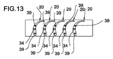
たとえば、図13に図示されたものによると、各々のロータ羽根20は、ネジ付きシート34と、そのネジ付きシート34の両側に設置される2つの穴39とを有し、ネジ付きシート34の中には(図12aの)ネジ32がねじ込まれ、2つの穴39には2つのピン38が設定される。
For example, according to what is illustrated in FIG. 13, each
補強リング23は、前述した貫通孔33と、ピン38用の2つの側部シート(図示せず)とを有する。図14の変形例において図示されたものによると、ロータ羽根20は、ネジ付きシート34を有し、ここに(図12aの)ネジ32がねじ込まれ、2つの隣接した羽根20には、ピン38用の穴39を有する。
The reinforcing
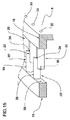
図15及び図16は、前述した製造方法の変形例を図示する。この変形例によると、環状のセットのロータ羽根20の半分は、ロータディスク6と一体に作られ、同一セットの前記ロータ羽根の他の半分は、補助ロータ羽根20'と呼ばれるが、これらは、それぞれの補強リング23と一体に作られる。
15 and 16 show a modified example of the above-mentioned manufacturing method. According to this variant, half of the
そのため、この変形例に従う方法は、(例えば、第1実施形態の為に前述したフライス加工または放電加工によって)補強リング23の各々と一体に環状のセットの補助羽根20'を作るステップを含み、前記補助ロータ羽根20'は、補強リング23の中心軸「X−X」の周りに配置され、当該方法は、各々の補助ロータ羽根20'を同一の環状のセットのロータディスクの2つのロータ羽根20の間に配置し、その補助ロータ羽根20'の末端部をロータディスク6の前面7に付けることによって補強リング23の各々を付けるステップを含む。
Therefore, the method according to this variant comprises the step of making an annular set of auxiliary blades 20'integral with each of the reinforcing rings 23 (eg, by milling or electrical discharge machining described above for the first embodiment). The auxiliary rotor blades 20'are arranged around the central axis "XX" of the reinforcing
図15に図示されるように、ロータディスク6と一体に作られたロータ羽根20のピッチは、完全な環状のセット羽根のピッチの2倍である。補強リング23と一体に作られた補助ロータ羽根20'のピッチも、完全な環状のセット羽根のピッチの2倍である。各々の補助羽根20'は、前縁部21'と、補強リング23の中心軸「X−X」に対して実質的に平行な後縁部22'とを有する。
As illustrated in FIG. 15, the pitch of the
ロータディスク6は、貫通孔33を有し、この貫通孔33は、後面8に開口し、2つのロータ羽根20の間の根元リング18の面31にも開口する。ロータディスク6は、ピン38の為の穴39を有し、この穴39は、ロータ羽根20に設けられ、前記ロータ羽根20の末端面に開口する。
The
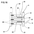
補強リング23は、ピン38の為の穴39を有し、この穴39は、補助ロータ羽根20'を担持する面であって、2つの連続した補助ロータ羽根20'の間で開口する。補強リング23は、ネジ付きシート34を有し、このネジ付きシート34は、補助ロータ羽根20'に設けられ、前記補助ロータ羽根20'の末端面に開口する。
The reinforcing
ネジ32は、貫通孔33に挿入され、補助ロータ羽根20'のネジ付きシート34にねじ込まれる。ピン38は、補強リング23およびロータ羽根20の穴39に挿入される(図16)。
The
いったん補強リング23がロータディスク6に装着されると、セット羽根は、ディスク6のロータ羽根20および補助ロータ羽根20'が交互に構成され、ピッチ(ロータ羽根20および隣接した補助ロータ羽根20'の間の周方向の距離)は正しいピッチになる。
Once the reinforcing
図17は、前述した製造方法の追加の変形例を図示するが、ここで、全ての羽根は、補強リング23上に一体で成形された補助ロータ羽根20'である。このため、想像されることは、(図17に一点鎖線で示された)固体リング100が準備され、その固体リング100から、それぞれの環状のセットの補助ロータ羽根20'が画定されるまで材料が除去されることである。
FIG. 17 illustrates an additional modification of the manufacturing method described above, wherein all the blades are auxiliary rotor blades 20' integrally molded on the reinforcing
ディスク6が得られる、この固体ディスク27は、それよりも、前面7に複数の環状レリーフ28を形成するように機械加工されるが、前記環状レリーフ28は、羽根を持たない(図17には1つだけが見られる)根元リング18を画定し、前記ディスク6の中心軸「X−X」と同心かつ同軸である。
ロータディスク6は、貫通孔33を有し、この貫通孔33は、補強リング23の補助ロータ羽根20'の各々において、後面8および根元リング18の面に開口する。補強リング23は、ネジ付きシート34を有し、このネジ付きシート34は、前記補助ロータ羽根20'の末端面に開口する。ネジ32は、貫通孔33に挿入され、補助ロータ羽根20'のネジ付きシート34にねじ込まれる。
The
Claims (14)
前面(7)を備えたディスク(6,14)を準備するステップと、
異なる直径の複数の補強リング(23)を準備するステップと、
を含み、
前記ディスク(6,14)を準備するステップは、
前記ディスク(6,14)と一体に環状のセットの羽根(20)を実現する工程を含み、前記セットの羽根(20)は、前記ディスク(6,14)の中心軸(X−X)と同心かつ同軸であり、前記前面(7)に配置され、各々の羽根(20)は、前縁部(21)と、前記中心軸(X−X)に対して実質的に平行な後縁部(22)とを有し、さらに/または、
複数の補強リング(23)を準備するステップは、
前記補強リング(23)の中心軸(X−X)の周りに配置された環状のセットの補助羽根(20')を、前記補強リング(23)の各々と一体で実現する工程を含み、各々の補助羽根(20')は、前縁部(21')と、前記補強リング(23)の前記中心軸(X−X)に対して実質的に平行の後縁部(22')とを有し、前記方法は、
前記環状のセットの羽根(20)及び/又は補助羽根(20')の一つに向かって前記ディスク(6,14)に前記補強リング(23)の各々を付けるステップを含み、
前記前面(7)に、環状のセットの羽根(20)及び/又は補助羽根(20')を画定し、各々には、それぞれの補強リング(23)が設けられ、
前記ディスク(6,14)を準備するステップは、
固体ディスク(27)を準備する工程と、
前記固体ディスク(27)から材料を除去し、前記前面(7)に複数の環状レリーフ(28)を画定する工程であって、前記複数の環状レリーフ(28)は、前記ディスク(6,14)の中心軸(X−X)と同心かつ同軸である、前記工程と、
各々の環状レリーフ(28)に対して、前記環状のセットの羽根(20)の一つが画定されるまで各々の環状レリーフ(28)から材料を除去する工程と、
を含み、
前記補強リング(23)の各々が、前記ディスク(6,14)の前記羽根(20)の末端部に付けられ、
各々の補強リング(23)を準備するステップは、
固体リング(100)を準備する工程と、
それぞれの環状のセットの補助羽根(20')が画定されるまで、前記固体リング(100)から材料を除去する工程と、
を含み、
前記羽根および/または前記補助羽根を画定する為の材料の除去は、フライス加工および/または放電加工によって実行される、方法。 A method for manufacturing bladed discs for radial turbomachinery.
Steps to prepare the discs (6,14) with the front (7),
With the step of preparing multiple reinforcing rings (23) of different diameters,
Including
The step of preparing the discs (6, 14) is
A step of realizing an annular set of blades (20) integrally with the disc (6,14) is included, wherein the blade (20) of the set is with a central axis (XX) of the disc (6,14). Concentric and coaxial, arranged on the front surface (7), each blade (20) has a leading edge portion (21) and a trailing edge portion substantially parallel to the central axis (XX). (22) and / or
The step of preparing multiple reinforcing rings (23) is
Each includes a step of realizing an annular set of auxiliary blades (20') arranged around the central axis (XX) of the reinforcing ring (23) integrally with each of the reinforcing rings (23). The auxiliary blade (20') has a leading edge portion (21') and a trailing edge portion (22') substantially parallel to the central axis (XX) of the reinforcing ring (23). And the above method
Includes the step of attaching each of the reinforcing rings (23) to the discs (6, 14) towards one of the annular set of blades (20) and / or auxiliary blades (20').
An annular set of blades (20) and / or auxiliary blades (20') are defined on the front surface (7), each provided with a respective reinforcing ring (23).
The step of preparing the discs (6, 14) is
The process of preparing the solid disk (27) and
A step of removing a material from the solid disk (27) and defining a plurality of annular reliefs (28) on the front surface (7), wherein the plurality of annular reliefs (28) are the disks (6, 14). Concentric and coaxial with the central axis (XX) of
For each annular relief (28), a step of removing material from each annular relief (28) until one of the blades (20) of the annular set is defined.
Including
Each of the reinforcing rings (23) is attached to the end of the blade (20) of the disc (6, 14).
The steps to prepare each reinforcing ring (23) are:
The process of preparing the solid ring (100) and
A step of removing material from the solid ring (100) until the auxiliary blades (20') of each annular set are defined.
Including
A method in which the removal of the blade and / or the material for defining the auxiliary blade is performed by milling and / or electrical discharge machining.
環状のセットの前記ディスク(6,14)の2つの羽根(20)の間に各々の補助羽根(20')を設置する工程と、
前記ディスク(6,14)の前記前面(7)に前記補助羽根(20')の末端部を付ける工程と、
を含む、請求項2に記載の方法。 The step of attaching each of the reinforcing rings (23) is
The step of installing each auxiliary blade (20') between the two blades (20) of the disk (6, 14) of the annular set, and
A step of attaching the end portion of the auxiliary blade (20') to the front surface (7) of the disk (6, 14), and
2. The method according to claim 2.
前記ディスク(6,14)の前記前面(7)に付けられる根元リング(18)の成形を含み、それぞれの環状のセットの前記羽根(20)は、前記根元リング(18)から突出する、請求項1〜3のいずれか一項に記載の方法。 The step of defining the annular set of blades (20) for each annular relief is:
Claimed, comprising forming a root ring (18) attached to the front surface (7) of the discs (6, 14), the blades (20) of each annular set projecting from the root ring (18). Item 1. The method according to any one of Items 1 to 3.
Applications Claiming Priority (3)
| Application Number | Priority Date | Filing Date | Title |
|---|---|---|---|
| IT102016000032704 | 2016-03-30 | ||
| ITUA2016A002126A ITUA20162126A1 (en) | 2016-03-30 | 2016-03-30 | Method for the construction of bladed discs for radial turbomachinery and bladed disc obtained by this method |
| PCT/IB2017/051784 WO2017168335A1 (en) | 2016-03-30 | 2017-03-29 | Method for the construction of bladed discs for radial turbomachines and a bladed disc obtained by means of this method |
Publications (2)
| Publication Number | Publication Date |
|---|---|
| JP2019510921A JP2019510921A (en) | 2019-04-18 |
| JP6972473B2 true JP6972473B2 (en) | 2021-11-24 |
Family
ID=56413738
Family Applications (1)
| Application Number | Title | Priority Date | Filing Date |
|---|---|---|---|
| JP2018550796A Active JP6972473B2 (en) | 2016-03-30 | 2017-03-29 | A method for manufacturing a bladed disc for a radial turbomachinery and a bladed disc obtained by this method. |
Country Status (5)
| Country | Link |
|---|---|
| US (1) | US10914174B2 (en) |
| EP (1) | EP3436667A1 (en) |
| JP (1) | JP6972473B2 (en) |
| IT (1) | ITUA20162126A1 (en) |
| WO (1) | WO2017168335A1 (en) |
Families Citing this family (2)
| Publication number | Priority date | Publication date | Assignee | Title |
|---|---|---|---|---|
| ITUB20161145A1 (en) * | 2016-02-29 | 2017-08-29 | Exergy Spa | Method for the construction of bladed rings for radial turbomachinery and bladed ring obtained by this method |
| IT201700028266A1 (en) * | 2017-03-14 | 2018-09-14 | Exergy Spa | Method for constructing bladed rings for radial turbomachinery |
Family Cites Families (18)
| Publication number | Priority date | Publication date | Assignee | Title |
|---|---|---|---|---|
| FR354110A (en) * | 1905-05-08 | 1905-09-29 | Otto Kolb | Radial action turbine operating by steam, gas or air, at several degrees of pressure and speed |
| FR372609A (en) * | 1906-12-15 | 1907-04-12 | Arthur Patschke | Turbine |
| GB360177A (en) * | 1929-11-23 | 1931-11-05 | Siemens Ag | Improvements in or relating to blading for radial flow turbines |
| GB2221259A (en) * | 1988-07-30 | 1990-01-31 | John Kirby | Turbines pumps & compressors |
| WO1993010358A1 (en) * | 1991-11-15 | 1993-05-27 | Moskovskoe Obschestvo Soznaniya Krishny | Method of forming air flow in outlet system of a centrifugal compressor and centrifugal compressor |
| IT1319495B1 (en) * | 2000-11-30 | 2003-10-20 | Nuovo Pignone Spa | PROCEDURE FOR THE CONSTRUCTION OF A ROTOR FOR COMPRESSOR-CENTRIFUGHI. |
| US7204926B2 (en) * | 2001-11-26 | 2007-04-17 | General Electric Company | Tandem blisk electrochemical machining |
| US20050247569A1 (en) * | 2004-05-07 | 2005-11-10 | Lamphere Michael S | Distributed arc electroerosion |
| JP2006037791A (en) * | 2004-07-26 | 2006-02-09 | Jfe Engineering Kk | Radial flow type steam turbine |
| DE102008019332A1 (en) * | 2008-04-16 | 2009-10-22 | Rolls-Royce Deutschland Ltd & Co Kg | Method for milling blisks |
| JP2012187660A (en) * | 2011-03-10 | 2012-10-04 | Mitsubishi Heavy Ind Ltd | Method for processing metal |
| US9878387B2 (en) * | 2012-05-08 | 2018-01-30 | United Technologies Corporation | Electrical discharge machining electrode |
| ITMI20121806A1 (en) * | 2012-10-24 | 2014-04-25 | Exergy Spa | METHOD TO BUILD STAGES OF CENTRIFUGAL RADIAL TURBINES |
| KR101383782B1 (en) * | 2013-02-25 | 2014-04-10 | 주식회사 한라이비텍 | Method for manufacturing super high-speed shroud impeller for gas compressor |
| RU2016140623A (en) * | 2014-03-21 | 2018-04-23 | Эксерджи С.П.А. | CENTRIFUGAL RADIAL TURBINE |
| US10876406B2 (en) * | 2014-03-21 | 2020-12-29 | Exergy S.P.A. | Radial turbomachine |
| CN106661943A (en) * | 2014-05-05 | 2017-05-10 | 埃克塞基股份公司 | Radial turbomachine |
| KR102208490B1 (en) * | 2014-07-07 | 2021-01-27 | 한화에어로스페이스 주식회사 | Method for manufacturing rotation part of rotary machine |
-
2016
- 2016-03-30 IT ITUA2016A002126A patent/ITUA20162126A1/en unknown
-
2017
- 2017-03-29 EP EP17724440.7A patent/EP3436667A1/en not_active Withdrawn
- 2017-03-29 WO PCT/IB2017/051784 patent/WO2017168335A1/en active Application Filing
- 2017-03-29 US US16/090,425 patent/US10914174B2/en active Active
- 2017-03-29 JP JP2018550796A patent/JP6972473B2/en active Active
Also Published As
| Publication number | Publication date |
|---|---|
| JP2019510921A (en) | 2019-04-18 |
| US10914174B2 (en) | 2021-02-09 |
| ITUA20162126A1 (en) | 2017-09-30 |
| EP3436667A1 (en) | 2019-02-06 |
| WO2017168335A1 (en) | 2017-10-05 |
| US20190112929A1 (en) | 2019-04-18 |
Similar Documents
| Publication | Publication Date | Title |
|---|---|---|
| US8403645B2 (en) | Turbofan flow path trenches | |
| JP6025962B2 (en) | Turbine rotor and turbocharger incorporating the turbine rotor | |
| JP6940486B2 (en) | High-rigidity turbomachinery impellers, turbomachinery including said impellers, and manufacturing methods | |
| US20190128126A1 (en) | Turbine blisk and method of manufacturing thereof | |
| CN105715303B (en) | Exhaust-driven turbo-charger exhaust-gas turbo charger | |
| JP6972473B2 (en) | A method for manufacturing a bladed disc for a radial turbomachinery and a bladed disc obtained by this method. | |
| CN104251232B (en) | Axial flow turbo-machine compressor drum with blades double fixed form | |
| EP3081747B1 (en) | Rotating machine with cooling channels | |
| JP2015075108A (en) | Shrouded turbine blisk and method of manufacturing the same | |
| CN105874213B (en) | Centrifugal compressor and diffuser manufacture method | |
| WO2014189702A1 (en) | A balanced mixed flow turbine wheel | |
| JP6884963B2 (en) | A method for manufacturing a bladed ring for a radius-flow turbomachinery and a bladed ring obtained using the above method. | |
| EP3612721B1 (en) | Method for the construction of bladed rings for radial turbomachinery | |
| EP3196417A1 (en) | Rim face scallop for integrally bladed rotor disk | |
| WO2022137794A1 (en) | Centrifugal compressor, and method for manufacturing same | |
| JP2024021887A (en) | Vane of rotary impeller of turbomachine, rotary impeller of turbomachine, method for manufacturing vane of rotary impeller of turbomachine, and method for manufacturing rotary impeller of turbomachine | |
| KR100988581B1 (en) | Method manufacturing of impeller for high pressure steam turbine | |
| RU2630925C1 (en) | Ninth stage impeller wheel of high pressure compressor (hpc) rotor of turbocharger engine, hpc rotor impeller wheel disc, hpc rotor impeller wheel blade, hpc rotor impeller wheel blade ring | |
| RU2573417C2 (en) | Turbojet engine low-pressure compressor rotor shaft (versions) | |
| JP2019094900A (en) | Turbine guide apparatus |
Legal Events
| Date | Code | Title | Description |
|---|---|---|---|
| RD04 | Notification of resignation of power of attorney |
Free format text: JAPANESE INTERMEDIATE CODE: A7424 Effective date: 20190918 |
|
| A621 | Written request for application examination |
Free format text: JAPANESE INTERMEDIATE CODE: A621 Effective date: 20200326 |
|
| A711 | Notification of change in applicant |
Free format text: JAPANESE INTERMEDIATE CODE: A711 Effective date: 20200605 |
|
| A977 | Report on retrieval |
Free format text: JAPANESE INTERMEDIATE CODE: A971007 Effective date: 20210225 |
|
| A131 | Notification of reasons for refusal |
Free format text: JAPANESE INTERMEDIATE CODE: A131 Effective date: 20210302 |
|
| A521 | Request for written amendment filed |
Free format text: JAPANESE INTERMEDIATE CODE: A523 Effective date: 20210527 |
|
| A131 | Notification of reasons for refusal |
Free format text: JAPANESE INTERMEDIATE CODE: A131 Effective date: 20210907 |
|
| A521 | Request for written amendment filed |
Free format text: JAPANESE INTERMEDIATE CODE: A523 Effective date: 20210909 |
|
| TRDD | Decision of grant or rejection written | ||
| A01 | Written decision to grant a patent or to grant a registration (utility model) |
Free format text: JAPANESE INTERMEDIATE CODE: A01 Effective date: 20211005 |
|
| A61 | First payment of annual fees (during grant procedure) |
Free format text: JAPANESE INTERMEDIATE CODE: A61 Effective date: 20211011 |
|
| R150 | Certificate of patent or registration of utility model |
Ref document number: 6972473 Country of ref document: JP Free format text: JAPANESE INTERMEDIATE CODE: R150 |