JP6972180B2 - How to support QoS and SMF - Google Patents
How to support QoS and SMF Download PDFInfo
- Publication number
- JP6972180B2 JP6972180B2 JP2019569773A JP2019569773A JP6972180B2 JP 6972180 B2 JP6972180 B2 JP 6972180B2 JP 2019569773 A JP2019569773 A JP 2019569773A JP 2019569773 A JP2019569773 A JP 2019569773A JP 6972180 B2 JP6972180 B2 JP 6972180B2
- Authority
- JP
- Japan
- Prior art keywords
- access
- qos
- 3gpp
- pdu session
- smf
- Prior art date
- Legal status (The legal status is an assumption and is not a legal conclusion. Google has not performed a legal analysis and makes no representation as to the accuracy of the status listed.)
- Active
Links
Images


Classifications
-
- H—ELECTRICITY
- H04—ELECTRIC COMMUNICATION TECHNIQUE
- H04W—WIRELESS COMMUNICATION NETWORKS
- H04W28/00—Network traffic management; Network resource management
- H04W28/02—Traffic management, e.g. flow control or congestion control
- H04W28/0268—Traffic management, e.g. flow control or congestion control using specific QoS parameters for wireless networks, e.g. QoS class identifier [QCI] or guaranteed bit rate [GBR]
-
- H—ELECTRICITY
- H04—ELECTRIC COMMUNICATION TECHNIQUE
- H04L—TRANSMISSION OF DIGITAL INFORMATION, e.g. TELEGRAPHIC COMMUNICATION
- H04L47/00—Traffic control in data switching networks
- H04L47/10—Flow control; Congestion control
- H04L47/24—Traffic characterised by specific attributes, e.g. priority or QoS
-
- H—ELECTRICITY
- H04—ELECTRIC COMMUNICATION TECHNIQUE
- H04L—TRANSMISSION OF DIGITAL INFORMATION, e.g. TELEGRAPHIC COMMUNICATION
- H04L47/00—Traffic control in data switching networks
- H04L47/70—Admission control; Resource allocation
- H04L47/80—Actions related to the user profile or the type of traffic
- H04L47/805—QOS or priority aware
-
- H—ELECTRICITY
- H04—ELECTRIC COMMUNICATION TECHNIQUE
- H04W—WIRELESS COMMUNICATION NETWORKS
- H04W28/00—Network traffic management; Network resource management
- H04W28/02—Traffic management, e.g. flow control or congestion control
-
- H—ELECTRICITY
- H04—ELECTRIC COMMUNICATION TECHNIQUE
- H04W—WIRELESS COMMUNICATION NETWORKS
- H04W28/00—Network traffic management; Network resource management
- H04W28/02—Traffic management, e.g. flow control or congestion control
- H04W28/10—Flow control between communication endpoints
-
- H—ELECTRICITY
- H04—ELECTRIC COMMUNICATION TECHNIQUE
- H04W—WIRELESS COMMUNICATION NETWORKS
- H04W28/00—Network traffic management; Network resource management
- H04W28/02—Traffic management, e.g. flow control or congestion control
- H04W28/10—Flow control between communication endpoints
- H04W28/12—Flow control between communication endpoints using signalling between network elements
-
- H—ELECTRICITY
- H04—ELECTRIC COMMUNICATION TECHNIQUE
- H04W—WIRELESS COMMUNICATION NETWORKS
- H04W36/00—Hand-off or reselection arrangements
- H04W36/0005—Control or signalling for completing the hand-off
- H04W36/0011—Control or signalling for completing the hand-off for data sessions of end-to-end connection
- H04W36/0027—Control or signalling for completing the hand-off for data sessions of end-to-end connection for a plurality of data sessions of end-to-end connections, e.g. multi-call or multi-bearer end-to-end data connections
-
- H—ELECTRICITY
- H04—ELECTRIC COMMUNICATION TECHNIQUE
- H04W—WIRELESS COMMUNICATION NETWORKS
- H04W36/00—Hand-off or reselection arrangements
- H04W36/0005—Control or signalling for completing the hand-off
- H04W36/0011—Control or signalling for completing the hand-off for data sessions of end-to-end connection
- H04W36/0033—Control or signalling for completing the hand-off for data sessions of end-to-end connection with transfer of context information
- H04W36/0044—Control or signalling for completing the hand-off for data sessions of end-to-end connection with transfer of context information of quality context information
-
- H—ELECTRICITY
- H04—ELECTRIC COMMUNICATION TECHNIQUE
- H04W—WIRELESS COMMUNICATION NETWORKS
- H04W36/00—Hand-off or reselection arrangements
- H04W36/14—Reselecting a network or an air interface
-
- H—ELECTRICITY
- H04—ELECTRIC COMMUNICATION TECHNIQUE
- H04W—WIRELESS COMMUNICATION NETWORKS
- H04W76/00—Connection management
- H04W76/10—Connection setup
- H04W76/15—Setup of multiple wireless link connections
-
- H—ELECTRICITY
- H04—ELECTRIC COMMUNICATION TECHNIQUE
- H04W—WIRELESS COMMUNICATION NETWORKS
- H04W76/00—Connection management
- H04W76/10—Connection setup
- H04W76/15—Setup of multiple wireless link connections
- H04W76/16—Involving different core network technologies, e.g. a packet-switched [PS] bearer in combination with a circuit-switched [CS] bearer
-
- H—ELECTRICITY
- H04—ELECTRIC COMMUNICATION TECHNIQUE
- H04W—WIRELESS COMMUNICATION NETWORKS
- H04W48/00—Access restriction; Network selection; Access point selection
- H04W48/18—Selecting a network or a communication service
Landscapes
- Engineering & Computer Science (AREA)
- Computer Networks & Wireless Communication (AREA)
- Signal Processing (AREA)
- Mobile Radio Communication Systems (AREA)
Description
本発明は、次世代移動通信に関する。 The present invention relates to next-generation mobile communication.
移動通信システムの技術規格を制定する3GPPでは、4世代移動通信と関連した多様なフォーラム及び新しい技術に対応するために、2004年末から3GPP技術の性能を最適化させて向上させようとする努力の一環としてLTE/SAE(Long Term Evolution/System Architecture Evolution)技術に対する研究を始めた。 In 3GPP, which establishes technical standards for mobile communication systems, efforts will be made to optimize and improve the performance of 3GPP technology from the end of 2004 in order to respond to various forums and new technologies related to 4G mobile communication. As part of this, we have begun research on LTE / SAE (Long Term Evolution / System Archive Evolution) technology.
3GPP SA WG2を中心に進行されたSAEは、3GPP TSG RANのLTE作業と並行してネットワークの構造を決定し、異機種ネットワーク間の移動性をサポートすることを目的とするネットワーク技術に対する研究であって、最近3GPPの重要な標準化問題のうち1つである。これは3GPPシステムをIPベースの多様な無線接続技術をサポートするシステムに発展させるための作業であって、より向上したデータ送信能力で送信遅延を最小化する、最適化されたパケットベースのシステムを目標にして作業が進行されてきた。 SAE, which was conducted around 3GPP SA WG2, is a research on network technology aimed at determining the network structure in parallel with the LTE work of 3GPP TSG RAN and supporting mobility between heterogeneous networks. Recently, it is one of the important standardization problems of 3GPP. This is a task to develop the 3GPP system into a system that supports various IP-based wireless connection technologies, and is an optimized packet-based system that minimizes transmission delay with improved data transmission capability. Work has been progressing with the goal.
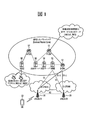
3GPP SA WG2で定義したEPS(Evolved Packet System)上位水準参照モデル(reference model)は、非ローミングケース(non−roaming case)及び多様なシナリオのローミングケース(roaming case)を含んでおり、詳細内容は、3GPP標準文書TS23.401とTS23.402で参照することができる。図1のネットワーク構造図は、これを簡略に再構成したものである。 The EPS (Evolved Packet System) reference model defined in 3GPP SA WG2 includes a non-roaming case and a roaming case of various scenarios. , 3GPP standard documents TS23.401 and TS23.402 can be referred to. The network structure diagram of FIG. 1 is a simplified reconstruction of this.
図1は、進化した移動通信ネットワークの構造図である。 FIG. 1 is a structural diagram of an evolved mobile communication network.
EPCは、多様な構成要素を含むことができ、図1は、そのうち一部に該当する、S−GW(Serving Gateway)52、PDN GW(Packet Data Network Gateway)53、MME(Mobility Management Entity)51、SGSN(Serving GPRS(General Packet Radio Service) Supporting Node)、ePDG(enhanced Packet Data Gateway)を示す。 The EPC can include various components, and FIG. 1 shows a part thereof, such as S-GW (Serving Gateway) 52, PDN GW (Packet Data Network Gateway) 53, and MME (Mobile Management Gateway) 51. , SGSN (Serving GPRS (General Packet Radio Service) Supporting Node), ePDG (enhanced Packet Data Gateway).
S−GW52は、無線アクセスネットワーク(RAN)とコアネットワークとの間の境界点として動作し、eNodeB22とPDN GW53との間のデータ経路を維持する機能をする要素である。また、端末(または、User Equipment:UE)がeNodeB22によりサービング(serving)される領域にわたって移動する場合、S−GW52は、ローカル移動性アンカーポイント(anchor point)の役割をする。即ち、E−UTRAN(3GPPリリース8以後で定義されるEvolved−UMTS(Universal Mobile Telecommunications System) Terrestrial Radio Access Network)内での移動性のために、S−GW52を介してパケットがルーティングされる。また、S−GW52は、他の3GPPネットワーク(3GPPリリース8以前に定義されるRAN、例えば、UTRANまたはGERAN(GSM(Global System for Mobile Communication)/EDGE(Enhanced Data rates for Global Evolution) Radio Access Network)との移動性のためのアンカーポイントとして機能することもできる。 The S-GW 52 is an element that operates as a boundary point between the radio access network (RAN) and the core network and functions to maintain a data path between the eNodeB 22 and the PDN GW 53. Further, when the terminal (or User Equipment: UE) moves over the area served by the eNodeB 22, the S-GW 52 acts as a local anchor point. That is, packets are routed via the S-GW 52 for mobility within E-UTRAN (Evolved-UMTS (Universal Mobile Telecommunications System) Terrestrial Radio Access Network defined after 3GPP Release 8). The S-GW 52 also includes other 3GPP networks (RANs defined prior to 3GPP Release 8, such as UTRAN or GERAN (GSM (Global System for Mobile Communication) / EDGE (Enhanced Data Radio Access Network) Network). It can also function as an anchor point for mobility with.
PDN GW(または、P−GW)53は、パケットデータネットワークに向かうデータインタフェースの終端点(termination point)に該当する。PDN GW53は、政策執行特徴(policy enforcement features)、パケットフィルタリング(packet filtering)、課金サポート(charging support)などをサポートすることができる。また、3GPPネットワークと非3GPPネットワーク(例えば、I−WLAN(Interworking Wireless Local Area Network)のような信頼されないネットワーク、CDMA(Code Division Multiple Access)ネットワークやWiMaxのような信頼されるネットワーク)との移動性管理のためのアンカーポイント役割をすることができる。 The PDN GW (or P-GW) 53 corresponds to the termination point of the data interface to the packet data network. The PDN GW 53 can support policy enforcement features, packet filtering, charging support, and the like. Also, mobility between 3GPP networks and non-3GPP networks (eg, unreliable networks such as I-WLAN (Interworking Wireless Local Area Network), trusted networks such as CDMA (Code Division Multiple Access) networks and WiMax). Can act as an anchor point for management.
図1のネットワーク構造の例示は、S−GW52とPDN GW53が別途のゲートウェイで構成されるものを示すが、二つのゲートウェイが単一ゲートウェイ構成オプション(Single Gateway Configuration Option)によって具現されることもできる。 The example of the network structure of FIG. 1 shows that the S-GW 52 and the PDN GW 53 are configured by separate gateways, but the two gateways can also be embodied by a single gateway configuration option (Single Gateway Configuration Option). ..
MME51は、UEのネットワーク連結に対するアクセス、ネットワークリソースの割当、トラッキング(tracking)、ページング(paging)、ローミング(roaming)及びハンドオーバなどをサポートするためのシグナリング及び制御機能を実行する要素である。MME51は、加入者及びセッション管理に関連した制御プレーン(control plane)機能を制御する。MME51は、数多くのeNodeB22を管理し、他の2G/3Gネットワークに対するハンドオーバのための従来のゲートウェイの選択のためのシグナリングを実行する。また、MME51は、セキュリティ過程(Security Procedures)、端末−対−ネットワークセッションハンドリング(Terminal−to−network Session Handling)、アイドル端末位置決定管理(Idle Terminal Location Management)などの機能を行う。 The MME 51 is an element that executes signaling and control functions for supporting access to the UE's network connection, allocation of network resources, tracking, paging, roaming, handover, and the like. The MME 51 controls control plane functions related to subscribers and session management. The MME 51 manages a number of eNodeBs 22 and performs signaling for the selection of conventional gateways for handovers to other 2G / 3G networks. In addition, the MME 51 performs functions such as security processes, terminal-to-network session handling, and idle terminal location management.
SGSNは、異なるアクセス3GPPネットワーク(例えば、GPRSネットワーク、UTRAN/GERAN)に対するユーザの移動性管理及び認証(authentication)といった全てのパケットデータをハンドリングする。 The SGSN handles all packet data such as user mobility management and authentication for different access 3GPP networks (eg GPRS networks, UTRAN / GERAN).
ePDGは、信頼できない非3GPPネットワーク(例えば、I−WLAN、WiFiホットスポット(hotspot)等)に対するセキュリティノードとしての役割をする。 The ePDG serves as a security node for unreliable non-3GPP networks (eg, I-WLAN, WiFi hotspots, etc.).
図1を参照して説明したように、IP能力を有する端末(または、UE)は、3GPPアクセスはもちろん非3GPPアクセスに基づいても、EPC内の多様な要素を経由して事業者(即ち、オペレータ(operator))が提供するIPサービスネットワーク(例えば、IMS)にアクセスすることができる。 As described with reference to FIG. 1, a terminal (or UE) with IP capability is an operator (ie, UE) via various elements within the EPC, based on 3GPP access as well as non-3GPP access. It is possible to access an IP service network (for example, IMS) provided by an operator (operator).
また、図1は、多様なレファレンスポイント(例えば、S1−U、S1−MME等)を示す。3GPPシステムでは、E−UTRAN及びEPCの異なる機能エンティティ(functional entity)に存在する2個の機能を連結する概念的なリンクをレファレンスポイント(reference point)と定義する。以下の表1は、図1に示すレファレンスポイントを整理したものである。表1の例示外にもネットワーク構造によって多様なレファレンスポイントが存在できる。 In addition, FIG. 1 shows various reference points (for example, S1-U, S1-MME, etc.). In the 3GPP system, a conceptual link connecting two functions existing in different functional entities of E-UTRAN and EPC is defined as a reference point. Table 1 below summarizes the reference points shown in FIG. In addition to the examples in Table 1, various reference points can exist depending on the network structure.

<次世代移動通信ネットワーク> <Next-generation mobile communication network>
4世代移動通信のためのLTE(long term evolution)/LTE−Advanced(LTE−A)の成功にこたえて、次世代、即ち、5世代(いわゆる5G)移動通信に対する関心も高まっており、研究も続々と進行している。 In response to the success of LTE (long term evolution) / LTE-Advanced (LTE-A) for 4th generation mobile communication, interest in the next generation, that is, 5th generation (so-called 5G) mobile communication is increasing, and research is also being conducted. It is progressing one after another.
国際電気通信連合(ITU)が定義する5世代移動通信は、最大20Gbpsのデータ送信速度とどこでも最小100Mbps以上の体感送信速度を提供するものを意味する。正式名称はIMT−2020’であり、世界的に2020年に商用化することを目標としている。 Five-generation mobile communications, as defined by the International Telecommunication Union (ITU), means providing data transmission speeds of up to 20 Gbps and perceived transmission speeds of at least 100 Mbps everywhere. The official name is IMT-2020', and the goal is to commercialize it worldwide in 2020.
ITUでは3代使用シナリオ、例えば、eMBB(enhanced Mobile BroadBand)mMTC(massive Machine Type Communication)及びURLLC(Ultra Reliable and Low Latency Communications)を提示している。 The ITU presents three-generation use scenarios, such as eMBB (enhanced Mobile Broadband) mMTC (massive Machine Type Communication) and URLLC (Ultra Reliable and Low Latency Communications).
まず、URLLCは、高い信頼性と低い遅延時間を要求する使用シナリオに関する。例えば、自動走行、工場自動化、増強現実のようなサービスは、高い信頼性と低い遅延時間(例えば、1ms以下の遅延時間)を要求する。現在4G(LTE)の遅延時間は、統計的に、21−43ms(best10%)、33−75ms(median)である。これは1ms以下の遅延時間を要求するサービスをサポートするに足りない。 First, URLLC relates to usage scenarios that require high reliability and low latency. For example, services such as autonomous driving, factory automation, and augmented reality require high reliability and low delay times (eg, delay times of 1 ms or less). Currently, the delay time of 4G (LTE) is statistically 21-43ms (best 10%), 33-75ms (median). This is insufficient to support services that require a delay time of 1 ms or less.
次に、eMBB使用シナリオは、移動超広帯域を要求する使用シナリオに関する。 Next, the eMBB usage scenario relates to a usage scenario that requires mobile ultra-wideband.
このような超広帯域の高速サービスは、既存LTE/LTE−Aのために設計されたコアネットワークによっては受容されにくい。 Such ultra-wideband high-speed services are less likely to be accepted by core networks designed for existing LTE / LTE-A.
従って、いわゆる5世代移動通信ではコアネットワークの再設計が切実に要求される。 Therefore, in so-called 5th generation mobile communication, redesign of the core network is urgently required.
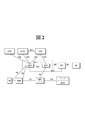
図2は、次世代移動通信の予想構造をノードの観点で示す例示図である。 FIG. 2 is an exemplary diagram showing the expected structure of next-generation mobile communication from the viewpoint of a node.
図2から分かるように、UEは、次世代RAN(Radio Access Network)を介してデータネットワーク(DN)と接続される。 As can be seen from FIG. 2, the UE is connected to a data network (DN) via a next-generation RAN (Radio Access Network).
図示された制御プレーン機能(Control Plane Function:CPF)ノードは、4世代移動通信のMME(Mobility Management Entity)の機能の全部又は一部、S−GW(Serving Gateway)及びP−GW(PDN Gateway)の制御プレーン機能の全部又は一部を行う。前記CPFノードは、AMF(Access and Mobility Management Function)とSMF(Session Management Function)を含む。 The illustrated Control Plane Function (CPF) node is all or part of the functions of the MME (Mobile Management Entry) of 4th generation mobile communication, S-GW (Serving Gateway) and P-GW (PDN Gateway). Performs all or part of the control plane function of. The CPF node includes AMF (Access and Mobility Management Function) and SMF (Session Management Function).
図示されたユーザプレーン機能(User Plane Function:UPF)ノードは、ユーザのデータが送受信されるゲートウェイの一種である。前記UPFノードは、4世代移動通信のS−GW及びP−GWのユーザプレーン機能の全部又は一部を行う。 The illustrated User Plane Function (UPF) node is a type of gateway to which user data is transmitted and received. The UPF node performs all or part of the user plane functions of the S-GW and P-GW of the 4th generation mobile communication.
図示されたPCF(Policy Control Function)は、事業者の政策を制御するノードである。 The illustrated PCF (Police Control Function) is a node that controls the policy of the business operator.
図示されたアプリケーション機能(Application Function:AF)は、UEに様々なサービスを提供するためのサーバである。 The illustrated application function (AF) is a server for providing various services to the UE.
図示された統合データ格納管理(Unified Data Management:UDM)は、4世代移動通信のHSS(Home subscriber Server)とともに、加入者情報を管理するサーバの一種である。前記UDMは、前記加入者情報を統合データリポジトリ(Unified Data Repository:UDR)に格納して管理する。 The illustrated integrated data management (UDM) is a kind of server that manages subscriber information together with HSS (Home subscriber Server) of 4th generation mobile communication. The UDM stores and manages the subscriber information in an integrated data repository (United Data Repository: UDR).
図示された認証サーバ機能(Authentication Server Function:AUSF)は、UEを認証及び管理する。 The illustrated authentication server function (AUSF) authenticates and manages the UE.
図示されたネットワークスライス選択機能(Network Slice Selection Function:NSSF)は、後述するようにネットワークスライシングのためのノードである。 The illustrated network slice selection function (NSSF) is a node for network slicing as described later.
図2においては、UEが2つのデータネットワークに多重PDU(Protocol Data Unit又はPacket Data Unit)セッションを利用して同時に接続することができる。 In FIG. 2, a UE can simultaneously connect to two data networks using a multiplex PDU (Protocol Data Unit or Packet Data Unit) session.
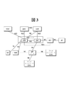
図3は、2つのデータネットワークに対する同時アクセスをサポートするためのアーキテクチャを示す例示図である。 FIG. 3 is an example diagram showing an architecture for supporting simultaneous access to two data networks.
図3においては、UEが1つのPDUセッションを使用して2つのデータネットワークに同時アクセスをするためのアーキテクチャが示されている。 FIG. 3 shows an architecture for a UE to access two data networks simultaneously using one PDU session.
<ネットワークスライス(Network Slice)> <Network Slice>
以下、次世代移動通信において導入されるネットワークのスライシングについて説明する。 The network slicing introduced in next-generation mobile communication will be described below.
次世代移動通信は、1つのネットワークを介して多様なサービスを提供するために、ネットワークのスライシングに対する概念を紹介している。ここで、ネットワークのスライシングは、特定サービスを提供するときに必要な機能を有するネットワークノードの組み合わせである。スライスインスタンスを構成するネットワークノードは、ハードウェア的に独立したノードであるか、又は論理的に独立したノードであり得る。 Next-generation mobile communication introduces the concept of network slicing in order to provide various services via one network. Here, network slicing is a combination of network nodes having functions necessary for providing a specific service. The network nodes that make up the slice instance can be hardware-independent nodes or logically independent nodes.
各スライスインスタンスは、ネットワーク全体の構成に必要な全てのノードの組み合わせで構成される。この場合、1つのスライスインスタンスは、UEに単独でサービスを提供することができる。 Each slice instance consists of a combination of all the nodes needed to configure the entire network. In this case, one slice instance can serve the UE independently.
これとは異なり、スライスインスタンスは、ネットワークを構成するノードのうち一部のノードの組み合わせで構成されることもできる。この場合、スライスインスタンスは、UEに単独でサービスを提供することなく、既存の他のネットワークノードと連係してUEにサービスを提供する。また、複数のスライスインスタンスが互いに連係してUEにサービスを提供することもできる。 Unlike this, a slice instance can also be composed of a combination of some of the nodes that make up the network. In this case, the slice instance provides the service to the UE in cooperation with other existing network nodes without providing the service to the UE alone. It is also possible for a plurality of slice instances to cooperate with each other to provide services to the UE.
スライスインスタンスは、コアネットワーク(CN)ノード及びRANを含む全体ネットワークノードが分離できる点で専用コアネットワークと異なる。また、スライスインスタンスは、単にネットワークノードが論理的に分離できるという点で専用コアネットワークと異なる。 Slice instances differ from dedicated core networks in that the core network (CN) node and the entire network node, including the RAN, can be separated. Slice instances also differ from dedicated core networks in that network nodes can simply be logically separated.
図4aは、ネットワークスライシングの概念を実現するためのアーキテクチャの例を示す例示図である。 FIG. 4a is an exemplary diagram showing an example of an architecture for realizing the concept of network slicing.
図4aから分かるように、コアネットワーク(CN)は、複数のスライスインスタンスに分けられることができる。各スライスインスタンスは、CP機能ノードとUP機能ノードのうち1つ以上を含むことができる。 As can be seen from FIG. 4a, the core network (CN) can be divided into a plurality of slice instances. Each slice instance can contain one or more of CP function nodes and UP function nodes.
各UEは、RANを介して自分のサービスに適合するネットワークスライスインスタンスを使用することができる。 Each UE can use a network slice instance that fits its service via RAN.
図4aの図示とは異なり、各スライスインスタンスは、CP機能ノードとUP機能ノードのうち1つ以上を他のスライスインスタンスと共有することもできる。これについて図4を参照して説明すると、以下のようである。 Unlike the illustration in FIG. 4a, each slice instance may also share one or more of the CP function node and the UP function node with other slice instances. This will be described with reference to FIG. 4 as follows.
図4bは、ネットワークスライシングの概念を実現するためのアーキテクチャの他の例を示す例示図である。 FIG. 4b is an exemplary diagram showing another example of the architecture for realizing the concept of network slicing.
図4bに示すように、複数のUP機能ノードがクラスタリングされ、同様に、複数のCP機能ノードもクラスタリングされる。 As shown in FIG. 4b, a plurality of UP function nodes are clustered, and similarly, a plurality of CP function nodes are also clustered.
そして、図4bに示すように、コアネットワーク内のスライスインスタンス♯1(又は、インスタンス♯1という)は、UP機能ノードの第1クラスタを含む。そして、前記スライスインスタンス♯1は、CP機能ノードのクラスタをスライスインスタンス♯2(又は、インスタンス♯2という)と共有する。前記スライスインスタンス♯2は、UP機能ノードの第2クラスタを含む。
Then, as shown in FIG. 4b, slice instance # 1 (or instance # 1) in the core network includes a first cluster of UP function nodes. Then, the
図示されたNSSFは、UEのサービスを収容できるスライス(又は、インスタンス)を選択する。 The illustrated NSSF selects a slice (or instance) that can accommodate the services of the UE.
図示されたUEは、前記NSSFにより選択されたスライスインスタンス#1を介してサービス♯1を利用することができ、また、前記Nにより選択されたスライスインスタンス♯2を介してサービス♯2を利用することができる。
The illustrated UE can utilize
<次世代移動通信ネットワークにおけるローミング> <Roaming in next-generation mobile communication networks>
一方、UEが訪問ネットワーク、例えば、VPLMN(Visited Public Land Mobile Network)にローミングした状況でUEからのシグナリング要求を処理する方式には2つが存在する。1番目の方式であるLBO(local breakout)方式は、UEからのシグナリング要求を訪問ネットワークにおいて処理する。2番目の方式であるHR(Home Routing)方式によると、訪問ネットワークはUEからのシグナリング要求をUEのホームネットワークに伝達する。 On the other hand, there are two methods for processing a signaling request from a UE in a situation where the UE roams to a visiting network, for example, a VPLMN (Visited Public Land Mobile Network). The first method, the LBO (local breakout) method, processes a signaling request from a UE in a visiting network. According to the second method, the HR (Home Routing) method, the visiting network transmits a signaling request from the UE to the home network of the UE.
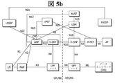
図5aは、ローミングのときにLBO(local breakout)方式が適用されるアーキテクチャを示す例示図であり、図5bは、ローミングのときにHR(home routed)方式が適用されるアーキテクチャを示す例示図である。 FIG. 5a is an exemplary diagram showing an architecture to which the LBO (local breakout) method is applied during roaming, and FIG. 5b is an exemplary diagram showing an architecture to which the HR (home routed) method is applied during roaming. be.
図5aに示すように、LBO方式が適用されるアーキテクチャにおいて、ユーザのデータはVPLMN内のデータネットワークに伝達される。このために、VPLMN内のPCFがVPLMN内でのサービスのためのPCC規則を生成するために、AFとインタラクションを行う。前記VPLMN内のPCFノードは、HPLMN(Home Public Land Mobile Network)事業者とのローミング協約に従って内部に設定された政策に基づいてPCC規則を生成する。 As shown in FIG. 5a, in the architecture to which the LBO method is applied, the user's data is transmitted to the data network in the VPLMN. To this end, the PCF within the VPLMN interacts with AF to generate PCC rules for services within the VPLMN. The PCF node in the VPLMN generates PCC rules based on the policy set internally according to the roaming agreement with the HPLMN (Home Public Land Mobile Network) operator.
図5bに示すように、HR方式が適用されるアーキテクチャにおいて、UEのデータはHPLMN内のデータネットワークに伝達される。 As shown in FIG. 5b, in the architecture to which the HR method is applied, the data of the UE is transmitted to the data network in the HPLMN.
<非3GPPネットワークへのデータ迂回> <Data bypass to non-3GPP network>
次世代移動通信において、UEのデータは、非3GPPネットワーク、例えば、WLAN(Wireless Local Area Network)又はWi−Fiに迂回されることができる。 In next-generation mobile communications, UE data can be diverted to non-3GPP networks, such as WLAN (Wireless Local Area Network) or Wi-Fi.
図6aないし図6fは、非3GPPネットワークにデータを迂回させるためのアーキテクチャを示す。 6a-6f show an architecture for bypassing data to a non-3GPP network.
WLAN(Wireless Local Area Network)又はWi−Fiは、信頼できない非3GPPネットワークとみなされる。前記非3GPPネットワークをコアネットワークに接続させるために、N3IWF(Non−3GPP InterWorking Function)が追加されることができる。 WLAN (Wireless Local Area Network) or Wi-Fi is considered an unreliable non-3GPP network. An N3IWF (Non-3GPP InterWorking Function) can be added to connect the non-3GPP network to the core network.
一方、PDUセッションは、3GPPアクセス及び非3GPPアクセスを介してそれぞれ生成できる。このように、相異なるアクセスで確立された2つの個別PDUセッションをバンドリングすることにより、多重アクセス(Multi Access:MA)PDUセッションを確立する概念が提案された。 On the other hand, PDU sessions can be created via 3GPP access and non-3GPP access, respectively. Thus, the concept of establishing a multiple access (MA) PDU session by bundling two individual PDU sessions established with different accesses has been proposed.
しかしながら、MA PDUセッションを確立するための具体的な方案と効率的に管理するための方案については議論されていないため、実現が不可能である問題点があった。 However, there was a problem that it was impossible to realize because the concrete plan for establishing the MA PDU session and the plan for efficient management were not discussed.
特に、MA PDUセッションに対して既存のQoS(quality of service)フレームワークが適用できないという問題点がある。 In particular, there is a problem that the existing QoS (Quality of Service) framework cannot be applied to the MA PDU session.
従って、本明細書の開示は、前述した問題点を解決することを目的とする。 Therefore, the disclosure of this specification is intended to solve the above-mentioned problems.
前記のような目的を達成するために、本明細書の一開示は、SMF(session management function)がQoS(quality of service)をサポートする方法を提供する。前記方法は、MA(multi−access) PDU(protocol data unit)セッション内のQoSフローがGBR(guaranteed bit rate) QoSフローではないことに基づいて、QoSプロファイルを3GPP(3rd generation partnership project)アクセス及び非3GPPアクセスの両方ともに送信すると決定するステップと、前記MA PDUセッション内のQoSフローが前記GBR QoSフローであることに基づいて、前記QoSプロファイルを3GPPアクセス及び非3GPPアクセスのうち1つのアクセスにのみ送信すると決定するステップと、前記決定に基づいて、前記QoSプロファイルを送信するステップとを含む。 In order to achieve the above object, one disclosure of the present specification provides a method in which an SMF (session management function) supports a quality of service (QoS). The method is based on the fact that the quality of service flow in an MA (multi-access) PDU (protocol data unit) session is not a GBR (guaranted bit rate) QoS flow, and the QoS profile is 3GPP (3rd generation participation non-select) access. The QoS profile is sent to only one of the 3GPP and non-3GPP accesses based on the step of determining to send both 3GPP accesses and the QoS flow in the MAPDU session being the GBR QoS flow. Then, a step of determining and a step of transmitting the QoS profile based on the determination are included.
前記方法は、前記3GPPアクセス及び前記非3GPPアクセスのうち前記1つのアクセスを決定するステップをさらに含む。 The method further comprises the step of determining the one of the 3GPP access and the non-3GPP access.
前記方法は、前記MA PDUセッションが確立されることに基づいて、QoS規則をUE(user equipment)に送信するステップをさらに含む。 The method further comprises the step of transmitting a quality of service (UE) to a UE (user equipment) based on the establishment of the MA PDU session.
前記QoS規則は、前記3GPPアクセス及び前記非3GPPアクセスの両方とものために共通的に使用されてもよい。 The QoS rules may be commonly used for both the 3GPP access and the non-3GPP access.
前記MA PDUセッションは、前記3GPPアクセス及び前記非3GPPアクセスの両方ともにおいて確立されてもよい。 The MA PDU session may be established in both the 3GPP access and the non-3GPP access.
前記方法は、ステアリング規則を端末とUPF(User Plane Function)のうち1つ以上に送信するステップをさらに含む。前記ステアリング規則は、前記QoSフローが前記1つのアクセスに同一にステアリングされるようにする。 The method further comprises transmitting the steering rule to one or more of the terminal and the User Plane Function (UPF). The steering rules ensure that the QoS flow is steered identically to the one access.
前記方法は、ステアリング規則に従って前記GBR QoSフローを前記3GPPアクセス及び非3GPPアクセスのうち第1アクセスから第2アクセスに移動しなければならない場合、UPFからスイッチングが必要であることを知らせるインジケーションを受信するステップをさらに含む。前記インジケーションは、スイッチングしようとするQoSフローに関する情報とスイッチングしようとする前記第2アクセスに関する情報を含む。 The method receives an indication from the UPF that switching is required if the GBR QoS flow must be moved from the first access to the second access of the 3GPP access and non-3GPP access according to steering rules. Including further steps to do. The indication includes information about the QoS flow to be switched and information about the second access to be switched.
前記方法は、前記SMFはGBR QoSフローのスイッチングが成功裏に行われたことを前記UPFに知らせるステップをさらに含む。前記QoSプロファイルは、前記インジケーションに基づいて送信されることができる。前記GBR QoSフローが成功裏に行われたことを知らせるインジケーションは、前記UPFにとって前記第2アクセスへのスイッチングを行うようにする。 The method further comprises the step of informing the UPF that the SMF has successfully switched the GBR QoS flow. The QoS profile can be transmitted based on the indication. The indication indicating that the GBR QoS flow has been successfully performed causes the UPF to switch to the second access.
前記QoSプロファイルが送信される1つのアクセスは、現在使用中のアクセスであり得る。前記QoSプロファイルは、前記現在使用中のアクセス上でリソースをセットアップするのに使用される。 One access to which the QoS profile is transmitted may be the access currently in use. The QoS profile is used to set up resources on the currently in-use access.
前記のような目的を達成するために、本明細書の一開示は、QoS(quality of service)をサポートするSMF(session management function)を提供する。前記SMFは、送受信部と、前記送受信部を制御するプロセッサとを含む。前記プロセッサは、MA(multi−access) PDU(protocol data unit)セッション内のQoSフローがGBR(guaranteed bit rate) QoSフローではないことに基づいて、QoSプロファイルを3GPP(3rd generation partnership project)アクセス及び非3GPPアクセスの両方ともに送信すると決定するステップと、前記MA PDUセッション内のQoSフローが前記のGBR QoSフローであることに基づいて、前記QoSプロファイルを3GPPアクセス及び非3GPPアクセスのうち1つのアクセスにのみ送信すると決定するステップと、前記決定に基づいて、前記QoSプロファイルを送信するステップとを行う。 In order to achieve the above object, one disclosure of the present specification provides an SMF (session management function) that supports quality of service (QoS). The SMF includes a transmission / reception unit and a processor that controls the transmission / reception unit. The processor has 3GPP (3rd generation partition) access and non-3GPP (3rd generation partition) access to the QoS profile based on the fact that the QoS flow in the MA (multi-access) PDU (protocol data unit) session is not a GBR (guaranted bit rate) QoS flow. Based on the step of determining to send both 3GPP accesses and the QoS flow in the MA PDU session being the GBP QoS flow, the QoS profile is assigned to only one of the 3GPP and non-3GPP accesses. A step of determining to transmit and a step of transmitting the QoS profile based on the determination are performed.
本明細書の開示によると、既存の問題点が解決される。 The disclosure of this specification solves an existing problem.
本明細書で使われる技術的用語は、単に特定の実施形態を説明するために使われたものであり、本発明を限定するものではないことに留意しなければならない。また、本明細書で使われる技術的用語は、本明細書で特別に他の意味で定義されない限り、本発明が属する技術分野において、通常の知識を有する者により一般的に理解される意味で解釈されなければならず、過度に包括的な意味または過度に縮小された意味で解釈されてはならない。また、本明細書で使われる技術的な用語が本発明の思想を正確に表現することができない技術的な用語である場合、当業者が正確に理解することができる技術的用語に変えて理解しなければならない。また、本発明で使われる一般的な用語は、辞書の定義によってまたは前後文脈によって解釈されなければならず、過度に縮小された意味で解釈されてはならない。 It should be noted that the technical terms used herein are used merely to describe a particular embodiment and are not intended to limit the invention. Also, the technical terms used herein are in the sense generally understood by those with ordinary knowledge in the art to which the invention belongs, unless otherwise defined herein. It must be interpreted and must not be interpreted in an overly comprehensive or overly reduced sense. Further, when the technical term used in the present specification is a technical term that cannot accurately express the idea of the present invention, it is understood by changing to a technical term that can be accurately understood by those skilled in the art. Must. Also, the general terms used in the present invention must be construed by the definition of a dictionary or by context and not in an overly reduced sense.
また、本明細書で使われる単数の表現は、文脈上、明白に異なる意味ではない限り、複数の表現を含む。本出願において、“構成される”または“有する”などの用語は、明細書上に記載された多様な構成要素、または複数のステップを必ず全て含むと解釈されてはならず、そのうち一部構成要素または一部ステップは含まれない場合もあり、または追加的な構成要素またはステップをさらに含む場合もあると解釈されなければならない。 Also, the singular representations used herein include multiple representations unless they have a distinctly different meaning in context. In this application, terms such as "consisting" or "having" shall not be construed to include all of the various components or steps described herein, of which some are partially composed. It must be construed that elements or partial steps may not be included, or may include additional components or steps.
また、本明細書で使われる第1及び第2などのように序数を含む用語は、多様な構成要素の説明に使われることができるが、前記構成要素は、前記用語により限定されてはならない。前記用語は、1つの構成要素を他の構成要素から区別する目的としてのみ使われる。例えば、本発明の権利範囲を外れない限り、第1の構成要素は第2の構成要素と命名することができ、同様に、第2の構成要素も第1の構成要素と命名することができる。 In addition, terms including ordinal numbers such as the first and the second used in the present specification can be used in the description of various components, but the components should not be limited by the terms. .. The term is used only for the purpose of distinguishing one component from the other. For example, the first component can be named the second component, and similarly, the second component can be named the first component as long as it does not deviate from the scope of rights of the present invention. ..
一構成要素が他の構成要素に“連結されている”または“接続されている”と言及された場合は、該当他の構成要素に直接的に連結されており、または接続されている場合もあるが、中間に他の構成要素が存在する場合もある。それに対し、一構成要素が他の構成要素に“直接連結されている”または“直接接続されている”と言及された場合は、中間に他の構成要素が存在しないと理解しなければならない。 When one component is mentioned as "connected" or "connected" to another component, it may be directly connected or connected to the other component. However, there may be other components in the middle. On the other hand, when one component is mentioned as "directly linked" or "directly connected" to another component, it must be understood that there is no other component in between.
以下、添付図面を参照して本発明による好ましい実施形態を詳細に説明し、図面符号に関係なしで同じまたは類似の構成要素は同じ参照番号を付与し、これに対する重複説明は省略する。また、本発明を説明するにあたって、関連した公知技術に対する具体的な説明が本発明の要旨を不明にすると判断される場合、その詳細な説明を省略する。また、添付図面は、本発明の思想を容易に理解することができるようにするためのものであり、添付図面により本発明の思想が制限されると解釈されてはならないことに留意しなければならない。本発明の思想は、添付図面外に全ての変更、均等物乃至代替物にまで拡張されると解釈されなければならない。 Hereinafter, preferred embodiments according to the present invention will be described in detail with reference to the accompanying drawings, and the same or similar components will be given the same reference number regardless of the drawing reference numerals, and duplicate description thereof will be omitted. Further, in explaining the present invention, if it is determined that a specific explanation for the related publicly known technique makes the gist of the present invention unclear, the detailed description thereof will be omitted. It should also be noted that the accompanying drawings are intended to facilitate the understanding of the ideas of the present invention and should not be construed as limiting the ideas of the present invention by the attached drawings. It doesn't become. The idea of the present invention must be construed to extend beyond the accompanying drawings to all modifications, equivalents or alternatives.
添付図面には例示的にUE(User Equipment)が示されているが、図示された前記UEは、端末(Terminal)、ME(Mobile Equipment)などの用語で呼ばれる場合もある。また、前記UEは、ノートブック、携帯電話、PDA、スマートフォン(Smart Phone)、マルチメディア機器などのように携帯可能な機器であり、またはPC及び車両搭載装置のように携帯不可能な機器である。 Although the attached drawing schematically shows a UE (User Equipment), the illustrated UE may be referred to by terms such as a terminal (Terminal) and ME (Mobile Equipment). Further, the UE is a portable device such as a notebook, a mobile phone, a PDA, a smartphone (Smart Phone), a multimedia device, or a non-portable device such as a PC and a vehicle-mounted device. ..
<用語の定義> <Definition of terms>
以下、図面を参照して説明する前に、本発明の理解を容易にするために、本明細書において使用される用語を簡略に定義する。 Hereinafter, the terms used in the present specification are briefly defined in order to facilitate the understanding of the present invention before the description with reference to the drawings.
UE/MS:User Equipment/Mobile Station、UE(100)装置を意味する。 UE / MS: User Equipment / Mobile Station, which means a UE (100) device.
EPS:Evolved Packet Systemの略語であり、LTE(Long Term Evolution)ネットワークをサポートするコアネットワークを意味する。UMTSが進化した形態のネットワーク。 EPS: An abbreviation for Evolved Package System, which means a core network that supports LTE (Long Term Evolution) networks. A network in which UMTS has evolved.
PDN(Public Data Network):サービスを提供するサーバが位置する独立的な網 PDN (Public Data Network): An independent network in which the server that provides the service is located.
PDN−GW(Packet Data Network Gateway):UEIP address allocation、Packet screening & filtering、Charging data collection機能を行うEPS網のネットワークノード PDN-GW (Packet Data Network Gateway): A network node of an EPS network that performs UEIP additional allocation, Packet drawing & filtering, and Charging data collection functions.
Serving GW(Serving Gateway):移動性担当(Mobility anchor)、パケットルーティング(Packet routing)、遊休モードパケットバッファリング(Idle mode packet buffering)、Triggering MME to page UE機能を行うEPS網のネットワークノード Serving GW (Serving Gateway): Mobility anchor, Packet routing, Idle mode packet buffering, Triggering MME to page UE function EPS network
eNodeB:EPS(Evolved Packet System)の基地局であり、屋外に設置され、セルカバレッジ規模はマクロセルに該当する。 eNodeB: An EPS (Evolved Packet System) base station, which is installed outdoors and has a cell coverage scale corresponding to a macro cell.
MME:Mobility Management Entityの略語であり、UEに対するセッションと移動性を提供するためにEPS内で各エンティティを制御する役割を果たす。 MME: Abbreviation for Mobility Management Entry, which plays a role in controlling each entity in the EPS to provide session and mobility for the UE.
セッション(Session):セッションは、データ送信のための通路であって、その単位は、PDN、Bearer、IP flow単位などになる。各単位の相違点は、3GPPにおいて定義したように対象ネットワーク全体単位(APN又はPDN単位)、その内においてQoSで区分する単位(Bearer単位)、目的地IPアドレス単位で区分することができる。 Session: A session is a passage for data transmission, and the unit thereof is a PDN, a Bearer, an IP flow unit, or the like. The difference between each unit can be classified by the entire target network unit (APN or PDN unit) as defined in 3GPP, the unit classified by QoS (Bearer unit), and the destination IP address unit.
APN:Access Point Nameの略語であり、ネットワークにおいて管理する接続ポイントの名前としてUEに提供される。すなわち、PDNを指すか、区分する文字列である。要求したサービスや網(PDN)に接続するためには、当該P−GWを経ることになるが、このP−GWを探すことができるように網内で予め定義した名前(文字列)である。例えば、APNは、internet.mnc012.mcc345.gprsのような形態になり得る。 APN: Abbreviation for Access Point Name, which is provided to the UE as the name of the connection point managed in the network. That is, it is a character string that points to or divides the PDN. In order to connect to the requested service or network (PDN), it goes through the P-GW, but it is a name (character string) predefined in the network so that this P-GW can be searched. .. For example, APN can be referred to as internet. mnc012. mcc345. It can be in the form of gprs.
PDN接続(connection):UEからPDNへの接続、すなわち、ipアドレスで表現されるUEとAPNで表現されるPDNとの連関(接続)を示す。これは、セッションが形成できるようにコアネットワーク内のエンティティ間の接続(UE100−PDN GW)を意味する。 PDN connection (connection): Indicates a connection from a UE to a PDN, that is, a connection between a UE represented by an ip address and a PDN represented by an APN. This means a connection (UE100-PDN GW) between entities in the core network so that a session can be formed.
UE Context:ネクワークにおいてUEを管理するために使用されるUEの状況情報、すなわち、UE id、移動性(現在位置など)、セッションの属性(QoS、優先順位など)で構成された状況情報 UE Context: Status information of the UE used to manage the UE in the nex, ie, status information composed of UE id, mobility (current location, etc.), session attributes (QoS, priority, etc.).
NAS(Non−Access−Stratum):UEとMME間の制御プレーン(Control Plane)の上位スペクトル(stratum)。UEとネットワーク間の移動性管理(Mobility management)とセッション管理(Session management)、IPアドレス管理(IP address maintenance)などをサポートする。 NAS (Non-Access-Stratum): Upper spectrum (stratum) of the control plane (Control Plane) between the UE and MME. It supports mobility management between UE and network, session management, IP address management, and so on.
PLMN:公衆陸上移動通信網(Public Land Mobile Network)の略語であり、事業者のネットワーク識別番号を意味する。UEのローミング状況において、PLMNはHome PLMN(HPLMN)とVisited PLMN(VPLMN)に区分される。 PLMN: An abbreviation for Public Land Mobile Network, which means a network identification number of a business operator. In the roaming situation of the UE, the PLMN is divided into a Home PLMN (HPLMN) and a Visited PLMN (VPLMN).
DNN:Data Network Nameの略語であり、APNに類似してネットワークにおいて管理する接続ポイントの名前としてUEに提供される。5GシステムにおいてDNNはAPNと同等に(equivalent)使用される。 DNN: An abbreviation for Data Network Name, which is provided to the UE as the name of a connection point managed in the network similar to APN. In a 5G system, DNN is used equivalently to APN.
NSSP(Network Slice Selection Policy):アプリケーションとS−NSSAI(Session Network Slice Selection Assistance Information)のマッピングのためにUEにより使用される。 NSSP (Network Slice Selection Policy): Used by the UE for mapping the application to the S-NSSAI (Session Information Session Selection Information).
<セッション及びサービス連続性(Session and Service Continuity)> <Session and Service Continuity>
次世代移動通信ネットワークにおいては、セッション及びサービス連続性(SSC)をサポートするために、様々なモードを提供する。 Next-generation mobile communication networks provide various modes to support session and service continuity (SSC).
1)SSCモード1
1)
PDU(Protocol Data Unit)セッション確立の過程で、PDUセッションアンカーとして動作するUPFはアクセステクノロジー(すなわち、アクセスタイプ及びセル)と関係なく維持される。IPタイプのPDUセッションの場合、IP連続性がUEの移動と関係なくサポートされる。SSCモード1は、どのようなPDUセッションタイプにも適用でき、また、どのようなアクセスタイプにも適用できる。
In the process of establishing a PDU (Protocol Data Unit) session, the UPF acting as a PDU session anchor is maintained regardless of the access technology (ie, access type and cell). For IP type PDU sessions, IP continuity is supported regardless of UE movement.
2)SSCモード2
2)
PDUセッションは、1つのPDUセッションのアンカーを有する場合、ネットワークはPDUセッションの解除をトリガし、UEに同一のPDUセッションの確立を指示することができる。前記新しいPDUセッションの確立過程で、PDUセッションのアンカーとして動作するUPFが新たに選択されることができる。SSCモード2は、どのようなPDUセッションタイプにも適用でき、また、どのようなアクセスタイプにも適用できる。
If the PDU session has one PDU session anchor, the network can trigger the release of the PDU session and instruct the UE to establish the same PDU session. In the process of establishing the new PDU session, an UPF that acts as an anchor for the PDU session can be newly selected.
3)SSCモード3
3)
SSCモード3に対するPDUセッションに対して、ネットワークは、UEと以前のPDUセッションのアンカーとの間の接続(connectivity)を解除する前に、同一のデータネットワークに対する新しいPDUセッションを利用するUEの接続確立を許容することができる。トリガ条件が適用される場合、ネットワークは、UEの新しい条件に適当なPDUセッションアンカー、すなわち、UPFを選択するか否かを決定することができる。SSCモード3は、どのようなPDUセッションタイプにも適用でき、また、どのようなアクセスタイプにも適用できる。
For a PDU session for
4)SSCモードの選択 4) Selection of SSC mode
UEのアプリケーション又はUEのアプリケーショングループと関連したSSCモードのタイプを決定するために、SSCモード選択政策が使用される。 The SSC mode selection policy is used to determine the type of SSC mode associated with the UE's application or UE's application group.
事業者は、UEに前記SSCモード選択政策を提供する。前記政策は、1つ以上のSSCモード選択政策規則を含むことができる。 The operator provides the UE with the SSC mode selection policy. The policy may include one or more SSC mode selection policy rules.
図7は、データストレージアーキテクチャを示す例示図である。 FIG. 7 is an exemplary diagram showing a data storage architecture.
図7に示すように、5Gシステムは、UDM(Unified Data Management)、PCF(Policy Control Function)、NEF(Network Exposure Function)がデータ、例えば、加入者情報、UDM及びPCFによる政策データ、NEFによるUEのためのAF要求情報などをUDR(Unified Data Repository)内に格納できるようにする。UDRは各PLMN内に配置されてもよい。 As shown in FIG. 7, in the 5G system, UDM (Unified Data Management), PCF (Police Control Foundation), NEF (Network Exposure Foundation) data, for example, subscriber information, policy data by UDM and PCF, N AF request information and the like can be stored in UDR (Unified Data Policy). The UDR may be located within each PLMN.
<登録手順> <Registration procedure>
UEは、移動追跡(mobility tracking)を可能にし、データ受信を可能にし、そして、サービスを受信するために、認可(authorise)を得る必要がある。このために、UEは、ネットワークに登録すべきである。登録手順は、UEが5Gシステムに対する初期登録をする必要があるときに行われる。また、前記登録手順は、UEが周期的登録アップデートを行うとき、遊休モードから新しいTA(tracking area)に移動するとき、そして、UEが周期的な登録更新を行う必要があるときに、行われる。 The UE needs to be authorized to enable mobility tracking, receive data, and receive services. For this, the UE should register with the network. The registration procedure is performed when the UE needs to perform initial registration for the 5G system. Further, the registration procedure is performed when the UE performs periodic registration update, when the UE moves from the idle mode to a new TA (tracking area), and when the UE needs to perform periodic registration update. ..
初期登録手順の間、UEのIDがUEから取得される。AMFは、PEI(IMEISV)をUDM、SMF及びPCFに伝達することができる。 The UE ID is obtained from the UE during the initial registration procedure. AMF can transmit PEI (IMEISV) to UDM, SMF and PCF.
図8は、例示的な登録手順を示す信号流れ図である。 FIG. 8 is a signal flow diagram showing an exemplary registration procedure.
1)UEは、RANにANメッセージを送信する。前記ANメッセージは、ANパラメータ、登録要求メッセージを含む。前記登録要求メッセージは、登録タイプ、加入者永久ID、又は臨時ユーザID、セキュリティパラメータ、NSSAI、UEの5G能力、PDUセッション状態などの情報を含む。 1) The UE sends an AN message to the RAN. The AN message includes an AN parameter and a registration request message. The registration request message includes information such as registration type, subscriber permanent ID, or temporary user ID, security parameters, NSSAI, UE 5G capability, PDU session status, and the like.
5GRANの場合、前記ANパラメータは、SUPI又は臨時ユーザID、選択されたネットワーク及びNSSAIを含む。 In the case of 5GRAN, the AN parameters include SUPI or temporary user ID, selected network and NSSAI.
登録タイプは、UEが「初期登録」(すなわち、UEが非登録状態にある)、「移動性登録アップデート」(すなわち、UEが登録された状態にあり、移動性により登録手順を開始する)、又は「定期登録アップデート」(すなわち、UEが登録された状態にあり、周期的なアップデートタイマー満了により登録手順を開始する)である否かを示すことができる。臨時ユーザIDが含まれている場合、前記臨時ユーザIDは、最後のサービングAMFを示す。UEが3GPPアクセスのPLMNと異なるPLMNにおいて非3GPPアクセスを介して既に登録された場合、UEは、非3GPPアクセスを介して登録手順の間、AMFにより割り当てられたUEの臨時IDを提供しないことがあり得る。 The registration types are "initial registration" of the UE (ie, the UE is in an unregistered state), "mobility registration update" (ie, the UE is in a registered state, and mobility initiates the registration procedure). Alternatively, it can indicate whether or not it is a "regular registration update" (that is, the UE is in the registered state and the registration procedure is started when the periodic update timer expires). If a temporary user ID is included, the temporary user ID indicates the last serving AMF. If the UE is already registered via non-3GPP access in a PLMN different from the PLMN of 3GPP access, the UE may not provide the temporary ID of the UE assigned by the AMF during the registration procedure via non-3GPP access. could be.
セキュリティパラメータは、認証及び無欠性保護のために使用される。 Security parameters are used for authentication and integrity protection.
PDUセッション状態は、UEにおいて使用可能な(以前に設定された)PDUセッションを示す。 The PDU session state indicates the (previously configured) PDU session available on the UE.
2)SUPIが含まれるか、臨時ユーザIDが有効なAMFを示さない場合、RANは、(R)AT及びNSSAIに基づいてAMFを選択することができる。 2) If SUPI is included or the temporary user ID does not indicate a valid AMF, the RAN can select the AMF based on (R) AT and NSSAI.
(R)ANが適切なAMFを選択できない場合、ローカル政策に従って任意のAMFを選択し、前記選択されたAMFに登録要求を伝達する。選択されたAMFがUEをサービスすることができない場合、選択されたAMFはUEのためにより適切な他のAMFを選択する。 (R) If the AN cannot select the appropriate AMF, it will select any AMF according to local policy and communicate the registration request to the selected AMF. If the selected AMF is unable to service the UE, the selected AMF will select another AMF that is more appropriate for the UE.
3)前記RANは、新しいAMFにN2メッセージを送信する。前記N2メッセージは、N2パラメータ、登録要求を含む。前記登録要求は、登録タイプ、加入者永久識別子又は臨時ユーザID、セキュリティパラメータ、NSSAI 及びMICOモード基本設定などを含む。 3) The RAN sends an N2 message to the new AMF. The N2 message includes an N2 parameter, a registration request. The registration request includes a registration type, a subscriber permanent identifier or temporary user ID, security parameters, NSSAI and MICO mode basic settings, and the like.
5G−RANが使われるとき、N2パラメータは、UEがキャンピングしているセルに関する位置情報、セル識別子及びRATタイプを含む。 When 5G-RAN is used, the N2 parameters include location information, cell identifiers and RAT types for the cells that the UE is camping on.
UEにより指示された登録タイプが周期的な登録更新であると、後述する過程4〜17は行われないこともあり得る。 If the registration type specified by the UE is periodic registration renewal, steps 4-17 described below may not be performed.
4)前記新たに選択されたAMFは、以前のAMFに情報要求メッセージ、例えば、Namf_Communication_UEContextTransferを送信することができる。 4) The newly selected AMF can send an information request message, for example, Namf_Communication_UEContextTransfer, to the previous AMF.
UEの臨時ユーザIDが登録要求メッセージに含まれ、サービングAMFが最後の登録以後に変更された場合、新しいAMFは、UEのSUPI及びMMコンテキストを要求するために完全な登録要求情報を含む情報要求メッセージを以前のAMFに送信することができる。 If the UE's temporary user ID is included in the registration request message and the serving AMF has changed since the last registration, the new AMF will request information containing the complete registration request information to request the UE's SUPI and MM context. The message can be sent to the previous AMF.
5)以前のAMFは、前記新たに選択されたAMFに情報応答メッセージ、例えば、Namf_Communication_UEContextTransfer responseを送信する。前記情報応答メッセージは、SUPI、MMコンテキスト、SMF情報を含む。 5) The previous AMF sends an information response message, for example, Namf_Communication_UEContextTransfer response, to the newly selected AMF. The information response message includes SUPI, MM context, and SMF information.
具体的に、以前のAMFは、UEのSUPI及びMMコンテキストを含む情報応答メッセージを送信する。 Specifically, the previous AMF sends an information response message containing the UE's SUPI and MM context.
−以前のAMFに活性PDUセッションに関する情報がある場合、前記以前のAMFにはSMFのID及びPDUセッションIDを含むSMF情報を前記情報応答メッセージ内に含めることができる。 -If the previous AMF has information about the active PDU session, the previous AMF can include the SMF information including the SMF ID and the PDU session ID in the information response message.
6)前記新しいAMFは、SUPIがUEにより提供されないか、以前のAMFから検索されない場合、UEにIdentity Requestメッセージを送信する。 6) The new AMF sends an Identity Request message to the UE if the SUPI is not provided by the UE or retrieved from the previous AMF.
7)前記UEは、前記SUPIを含むIdentity Responseメッセージを前記新しいAMFに送信する。 7) The UE sends an Identity Response message containing the SUPI to the new AMF.
8)AMFは、AUSFをトリガすると決定することができる。この場合、AMFは、SUPIに基づいて、AUSFを選択することができる。 8) AMF can be determined to trigger AUSF. In this case, AMF can select AUSF based on SUPI.
9)AUSFは、UE及びNASセキュリティ機能の認証を開始する。 9) AUSF starts authentication of UE and NAS security functions.
10)前記新しいAMFは、以前のAMFにNamf_Communication_RegistrationCompleteNotifyメッセージを送信することができる。 10) The new AMF can send a Namf_Communication_RegistrationCompleteNotify message to the old AMF.
11)前記新しいAMFは、UEにIdentity Requestメッセージを送信することができる。 11) The new AMF can send an Identity Request message to the UE.
PEIがUEにより提供されないか、以前のAMFから検索されない場合、AMFがPEIを検索するためにIdentity Requestメッセージが送信される。 If the PEI is not provided by the UE or is not retrieved from the previous AMF, an Identity Request message is sent for the AMF to retrieve the PEI.
12)前記新しいAMFは識別子を検査する。 12) The new AMF checks for identifiers.
13)後述する過程14が行われると、前記新しいAMFはSUPIに基づいてUDMを選択する。 13) When the process 14 described later is performed, the new AMF selects UDM based on SUPI.
14)前記新しいAMFは、UDMに登録手順を行う。 14) The new AMF performs a registration procedure with UDM.
15)前記新しいAMFは、SUPIに基づいてPCFを選択することができる。 15) The new AMF can select a PCF based on SUPI.
16)前記新しいAMFは、PCFにPolicy Association Establishmentを行う。 16) The new AMF performs a Polycy Association Establishment on the PCF.
17)前記新しいAMFは、SMFにPDU Session Update SM Contextメッセージ又はPDU Session Release SM Contextメッセージを送信する。 17) The new AMF sends a PDU Session Update SM Contact message or a PDU Session Release SM Continue message to the SMF.
18−19)前記新しいSMFは、N3IWFにAMF Mobility Requestメッセージを送信し、AMFからMobility Responseメッセージを受信する。 18-19) The new SMF sends an AMF Mobility Request message to the N3IWF and receives a Mobility Response message from the AMF.
20)前記以前のAMFは、UE Context Termination RequestメッセージをPCFに送信する。 20) The previous AMF sends a UE Context Termination Request message to the PCF.
前記以前のAMFがPCFにおいてUEコンテキストが設定されるように以前に要求していた場合、前記以前のAMFはPCFにおいてUEコンテキストを削除させることができる。 If the previous AMF previously requested that the UE context be set in the PCF, the previous AMF may have the UE context deleted in the PCF.
21)前記新しいAMFは、登録受諾メッセージをUEに送信する。前記登録受諾メッセージは、臨時ユーザID、登録領域、移動性制限、PDUセッション状態、NSSAI、定期登録アップデートタイマー及び許容されたMICOモードを含む。 21) The new AMF sends a registration acceptance message to the UE. The registration acceptance message includes a temporary user ID, registration area, mobility restriction, PDU session status, NSSAI, periodic registration update timer and allowed MICO mode.
前記AMFが新しい臨時ユーザIDを割り当てる場合、臨時ユーザIDが前記登録受諾メッセージ内にさらに含まれることができる。移動性制限がUE に適用される場合、移動性制限を示す情報が前記登録受諾メッセージ内に追加的に含まれることができる。AMFは、UEに対するPDUセッション状態を示す情報を登録受諾メッセージ内に含めることができる。UEは、受信されたPDUセッション状態において活性と表示されないPDUセッションと関連した任意の内部リソースを除去することができる。PDUセッション状態情報がRegistration Requestにあると、AMFはUEにPDUセッション状態を示す情報を前記登録受諾メッセージ内に含めることができる。 If the AMF assigns a new temporary user ID, the temporary user ID may be further included in the registration acceptance message. If the mobility restriction is applied to the UE, additional information indicating the mobility restriction may be included in the registration acceptance message. The AMF can include information indicating the PDU session status for the UE in the registration acceptance message. The UE can remove any internal resources associated with a PDU session that does not appear to be active in the received PDU session state. When the PDU session status information is in the Restriction Request, the AMF can include information indicating the PDU session status in the UE in the registration acceptance message.
22)前記UEは、前記新しいAMFに登録完了メッセージを送信する。 22) The UE sends a registration completion message to the new AMF.
<PDUセッション確立手順> <Procedure for establishing PDU session>
PDUセッション確立手順は、下記のように2つのタイプのPDUセッション確立手順が存在する。 There are two types of PDU session establishment procedures as described below.
−UEが開始するPDUセッション確立手順 -UE-initiated PDU session establishment procedure
−ネットワークが開始するPDUセッション確立手順。このために、ネットワークは、装置トリガメッセージをUEのアプリケーション(ら)に送信することができる。 -The procedure for establishing a PDU session to start the network. To this end, the network can send device-triggered messages to UE applications (and others).
図9は、例示的なPDUセッション確立手順を示す信号流れ図である。 FIG. 9 is a signal flow diagram showing an exemplary PDU session establishment procedure.
図9に示す手順は、図7に示す登録手順に従って、UEがAMF上に既に登録したと仮定する。従って、AMFは、既にUDMからユーザ加入データを取得していると仮定する。 The procedure shown in FIG. 9 assumes that the UE has already registered on the AMF according to the registration procedure shown in FIG. Therefore, it is assumed that the AMF has already acquired the user subscription data from the UDM.
1)UEは、AMFにNASメッセージを送信する。前記メッセージは、S−NSSAI、DNN、PDUセッションID、要求タイプ、N1 SM情報などを含む。 1) The UE sends a NAS message to the AMF. The message includes S-NSSAI, DNN, PDU session ID, request type, N1 SM information and the like.
新しいPDUセッションを確立するために、UEは新しいPDUセッションIDを生成することができる。 To establish a new PDU session, the UE can generate a new PDU session ID.
UEは、PDUセッション確立要求メッセージをN1 SM情報内に含めたNASメッセージを送信することにより、UEにより開始されるPDUセッション確立手順を開始することができる。前記PDUセッション確立要求メッセージは、要求タイプ、SSCモード、プロトコル構成オプションを含む。 The UE can start the PDU session establishment procedure started by the UE by transmitting the NAS message including the PDU session establishment request message in the N1 SM information. The PDU session establishment request message includes a request type, SSC mode, and protocol configuration options.
PDUセッション確立が新しいPDUセッションを設定するためのことである場合、要求タイプは「初期要求」を示す。しかしながら、3GPPアクセスと非3GPPアクセスとの間の既存PDUセッションが存在する場合、前記要求のタイプは「既存PDUセッション」を示すことができる。 If the PDU session establishment is for setting up a new PDU session, the request type indicates "initial request". However, if there is an existing PDU session between 3GPP access and non-3GPP access, the type of request can indicate "existing PDU session".
前記UEにより送信されるNASメッセージは、ANによりN2メッセージ内にエンキャプシュレートされる。前記N2メッセージは、AMFに送信され、ユーザ位置情報及びアクセス技術タイプ情報を含むことができる。 The NAS message transmitted by the UE is encapsulated by the AN in the N2 message. The N2 message is sent to the AMF and may include user location information and access technology type information.
−N1 SM情報は、外部DNによるPDUセッション認証に関する情報が含まれたSM PDU DN要求コンテナを含むことができる。 -N1 SM information can include an SM PDU DN request container that contains information about PDU session authentication by an external DN.
2)AMFは、メッセージが前記要求タイプが「初期要求」を示す場合、そして、前記PDUセッションIDがUEの既存PDUセッションのために使用されなかった場合、新しいPDUセッションに対する要求に該当すると決定することができる。 2) The AMF determines that if the message indicates that the request type is "initial request" and the PDU session ID is not used for an existing PDU session in the UE, then it corresponds to a request for a new PDU session. be able to.
NASメッセージがS−NSSAIを含まないと、AMFはUE加入によって要求されたPDUセッションに対するデフォルトS−NSSAIを決定することができる。AMFは、PDUセッションIDとSMFのIDを関連付けて格納することができる。 If the NAS message does not include S-NSSAI, the AMF can determine the default S-NSSAI for the PDU session requested by joining the UE. The AMF can store the PDU session ID and the SMF ID in association with each other.
3)AMFは、SMコンテキスト要求メッセージをSMFに送信する。 3) The AMF sends an SM context request message to the SMF.
4)SMFは、加入者データ要求メッセージをUDMに送信する。前記加入者データ要求メッセージは、加入者永久ID、DNNを含む。 4) The SMF sends a subscriber data request message to the UDM. The subscriber data request message includes a subscriber permanent ID and DNN.
前記の過程において要求タイプが「既存PDUセッション」を示す場合、SMFは、当該要求が3GPPアクセスと非3GPPアクセスの間のハンドオーバに起因したと決定する。SMFは、PDUセッションIDに基づいて既存PDUセッションを識別することができる。 If the request type indicates "existing PDU session" in the above process, the SMF determines that the request was due to a handover between 3GPP access and non-3GPP access. The SMF can identify an existing PDU session based on the PDU session ID.
SMFがまだDNNと関連したUEに対するSM関連加入データを検索していない場合、SMFは加入データを要求することができる。 If the SMF has not yet searched for SM-related subscription data for the UE associated with the DNN, the SMF may request the subscription data.
UDMは、加入データ応答メッセージをSMFに送信することができる。 The UDM can send a subscription data response message to the SMF.
加入データには、認証された要求タイプ、認証されたSSCモード、基本QoSプロファイルに関する情報が含まれる。 The subscription data includes information about the authenticated request type, the authenticated SSC mode, and the basic QoS profile.
SMFは、UE要求がユーザ加入及びローカル政策を遵守するか否かを確認することができる。または、SMFは、AMFにより伝達されたNAS SMシグナリング(関連SM拒否原因を含む)を介してUE要求を拒絶し、SMF は、AMFにPDUセッションIDが解除されたと見なされるべきであることを知らせる。 The SMF can confirm whether the UE request complies with user enrollment and local policies. Alternatively, the SMF rejects the UE request via NAS SM signaling (including the associated SM rejection cause) transmitted by the AMF, and the SMF informs the AMF that the PDU session ID should be considered released. ..
5)SMFは、AMFにCreate SM Context Responseメッセージを送信する。 5) The SMF sends a Create SM Context Response message to the AMF.
6)PDUセッション認証/許可手順が行われる。 6) The PDU session authentication / authorization procedure is performed.
7A)動的PCCが配布されると、SMFはPCFを選択する。 7A) When the dynamic PCC is distributed, the SMF selects the PCF.
7b)SMFは、PDUセッションに対する基本PCC規則を得るためにPCF側にPDU−CANセッション確立を開始することができる。過程3での要求タイプが「既存PDUセッション」を示すと、PCFは代わりにPDU−CANセッション修正を開始することができる。
7b) The SMF can start establishing a PDU-CAN session on the PCF side in order to obtain the basic PCC rules for the PDU session. If the request type in
7)過程3の要求タイプが「初期要求」を示すと、SMFはPDUセッションに対するSSCモードを選択する。
7) When the request type in
8)前記SMFはUPFも選択することができる。要求タイプIPv4又はIPv6の場合、SMFはPDUセッションに対するIPアドレス/プレフィックス(prefix)を割り当てることができる。 8) UPF can also be selected as the SMF. For request type IPv4 or IPv6, the SMF can assign an IP address / prefix to the PDU session.
9)SMFは、SM政策アソシエーション修正手順を行う。 9) The SMF carries out the SM policy association amendment procedure.
10a)要求タイプが「初期要求」を示し、過程5が行われない場合、SMFは、選択されたUPFを使用してN4セッション確立手順を開始し、そうでないと、選択されたUPFを使用してN4セッション修正手順を開始することができる。
10a) If the request type indicates "initial request" and
SMFは、UPFにN4セッション確立/修正要求メッセージを送信する。そして、前記SMFは、PDUセッションに対してUPFに設置されるパケット探知、試行及び報告規則を提供することができる。SMFがCNトンネル情報を割り当てる場合、CNトンネル情報がUPFに提供されることができる。 The SMF sends an N4 session establishment / correction request message to the UPF. The SMF can then provide packet detection, trial and reporting rules installed in the UPF for the PDU session. If the SMF assigns CN tunnel information, the CN tunnel information can be provided to the UPF.
10b)UPFは、N4セッションの確立/修正応答メッセージを送信することにより、応答することができる。CNトンネル情報がUPFにより割り当てられる場合、CNトンネル情報がSMFに提供されることができる。 10b) The UPF can respond by sending an N4 session establishment / correction response message. If the CN tunnel information is assigned by UPF, the CN tunnel information can be provided to the SMF.
11)前記SMFは、N1N2 Message TransferをAMFに送信する。前記メッセージはPDUセッションID、N2 SM情報を含む。前記N2 SM情報はPDUセッションID、QFI、QoSプロファイル、CNトンネル情報、許容NSSAIから得られるS−NSSAI情報、セッション−AMBR、PDUセッションタイプなどを含む。 11) The SMF transmits an N1N2 Message Transfer to the AMF. The message includes PDU session ID and N2 SM information. The N2 SM information includes PDU session ID, QFI, QoS profile, CN tunnel information, S-NSSAI information obtained from permissible NSSAI, session-AMBR, PDU session type and the like.
12)AMFは、RANとN2 PDUセッション要求メッセージを送信する。前記メッセージは、N2 SM情報、NASメッセージを含む。前記NASメッセージは、PDUセッションID、PDUセッション確立受諾メッセージを含む。 12) The AMF sends a RAN and an N2 PDU session request message. The message includes N2 SM information and NAS message. The NAS message includes a PDU session ID and a PDU session establishment acceptance message.
AMFは、PDUセッションID及びPDUセッション確立受諾メッセージを含むNASメッセージを送信することができる。また、AMFは、SMFから受信N2 SM情報をN2 PDUセッション要求メッセージ内に含めてRANに送信する。 The AMF can send a NAS message including a PDU session ID and a PDU session establishment acceptance message. Further, the AMF includes the received N2 SM information from the SMF in the N2 PDU session request message and transmits the received N2 SM information to the RAN.
13)RANは、SMFから受信された情報と関連したUEとの特定シグナリング交換をすることができる。 13) The RAN can perform a specific signaling exchange with the UE associated with the information received from the SMF.
RANはまた、PDUセッションに対してRAN N3トンネル情報を割り当てる。 The RAN also assigns RAN N3 tunnel information to the PDU session.
RANは、過程10で提供されたNASメッセージをUEに伝達する。前記NASメッセージは、PDUセッションID、N1 SM情報を含む。前記N1 SM情報は、PDUセッション確立受諾メッセージを含む。
The RAN conveys the NAS message provided in
RANは、必要なRANリソースが設定され、RANトンネル情報の割り当てが成功した場合にのみNASメッセージをUEに送信する。 The RAN sends a NAS message to the UE only when the necessary RAN resources are set and the RAN tunnel information allocation is successful.
14)RANは、AMFにN2 PDUセッション要求Ackを送信する。 14) The RAN sends an N2 PDU session request Ac to the AMF.
15)AMFは、SM要求メッセージをSMFに送信することができる。前記SM要求メッセージはN2 SM情報を含むことができる。ここで、前記AMFは、RANにおいて受信したN2 SM情報をSMFに伝達するものであり得る。 15) The AMF can send an SM request message to the SMF. The SM request message can include N2 SM information. Here, the AMF may transmit the N2 SM information received in the RAN to the SMF.
16a)前記PDUセッションに対するN4セッションが既に設定されていない場合、SMFはUPFとともにN4セッション確立手順を開始することができる。そうでない場合、SMFは、UPFを使用してN4セッション修正手順を開始することができる。SMFは、ANトンネル情報とCNトンネル情報を提供することができる。CNトンネル情報は、SMFが過程8でCNトンネル情報を選択した場合にのみ提供される。 16a) If the N4 session for the PDU session has not already been set, the SMF can start the N4 session establishment procedure together with the UPF. If not, the SMF can use the UPF to initiate the N4 session correction procedure. The SMF can provide AN tunnel information and CN tunnel information. The CN tunnel information is provided only if the SMF selects the CN tunnel information in step 8.
16b)前記UPFは、SMFにN4セッション確立/修正応答メッセージを送信することができる。 16b) The UPF can send an N4 session establishment / correction response message to the SMF.
17)SMFは、SM応答メッセージをAMFに送信することができる。この過程が終わると、AMFは関連イベントをSMFに伝達することができる。RANトンネル情報が変更されるか、AMFが再配置されるハンドオーバの時に発生する。 17) The SMF can send an SM response message to the AMF. At the end of this process, the AMF can propagate the relevant event to the SMF. Occurs when the RAN tunnel information is changed or the AMF is relocated in a handover.
18)SMFは、UPFを介してUEに情報を送信する。具体的に、PDU Type IPv6の場合、SMFは、IPv6 Router Advertisementを生成し、これをN4とUPFを介してUEに送信することができる。 18) The SMF transmits information to the UE via the UPF. Specifically, in the case of PDU Type IPv6, the SMF can generate an IPv6 Router IPv6 and send it to the UE via N4 and UPF.
19)前記SMFは、AMFにSM Context Status Notifyメッセージを送信する。 19) The SMF transmits an SM Context Status Notify message to the AMF.
20)前記SMFは、前記UPFを介してIPアドレス設定を伝達する。 20) The SMF transmits an IP address setting via the UPF.
<多重アクセス(Multi−Access:MA)PDUセッション> <Multi-access (Multi-Access: MA) PDU session>
従来技術においてMA PDUセッションは、他のアクセスで確立された2つの個別PDUセッションをバンドリングすることにより生成されることができる。 In the prior art, MA PDU sessions can be generated by bundling two individual PDU sessions established with other access.
図10は、従来技術によりMA PDUセッションが生成された例を示す。 FIG. 10 shows an example in which a MA PDU session is generated by the prior art.
MA PDUセッションは、図10においてチャイルド(child)PDUセッションとして現れた少なくとも2つのPDUセッションを含む。前記2つのPDUセッションのうち1つは3GPPアクセス上で確立されており、もう1つのPDUセッションは信頼できない(untrusted)非3GPPアクセス(例えば、WLAN AN)上で確立されている。 The MA PDU session includes at least two PDU sessions that appear as child PDU sessions in FIG. One of the two PDU sessions is established on 3GPP access and the other PDU session is established on untrusted non-3GPP access (eg, WLAN AN).
前記MA−PDUセッションにおいてチャイルドPDUセッションは下記の特徴を共有することができる。 In the MA-PDU session, the child PDU session can share the following features.
(i)共通DNN; (I) Common DNN;
(ii)共通UPFアンカー(anchor)(UPF−A); (Ii) Common UPF anchor (UPF-A);
(iii)共通PDUタイプ(例えば、IPv6); (Iii) Common PDU type (eg IPv6);
(iv)共通IPアドレス (Iv) Common IP address
(v) 共通SSCモード (V) Common SSC mode
(vi)共通S-NSSAI (Vi) Common S-NSSAI
MA−PDUセッションは、UEとUPF−Aの間に多重経路データリンクを可能にする。これは、IP層の下位において実現されることができる。 The MA-PDU session enables multiple path data links between the UE and UPF-A. This can be achieved below the IP layer.
MA−PDUセッションは、次の手順のうち1つにより確立されることができる。 A MA-PDU session can be established by one of the following steps:
(i)2つの個別的なPDUセッション確立手順により確立されることができる。これを「個別確立」という。 (I) It can be established by two separate PDU session establishment procedures. This is called "individual establishment".
(ii)1つのMA PDUセッション確立手順により確立されることができる。すなわち、2つのチャイルドPDUセッションが同時に確立される。これを「結合確立」という。 (Ii) It can be established by one MA PDU session establishment procedure. That is, two child PDU sessions are established at the same time. This is called "bond establishment".
複数のチャイルドPDUセッションは、同一のIPアドレスを有することができる。 Multiple child PDU sessions can have the same IP address.
MA−PDUセッションが確立された後、MA PDUセッションと関連したSM(Session Management)シグナリングが任意のアクセスを介して送受信されることができる。 After the MA-PDU session is established, SM (Session Management) signaling associated with the MA PDU session can be sent and received via any access.
A.MA PDUセッションの個別確立 A. Individual establishment of MA PDU session
2つのチャイルドPDUセッションが2つの個別PDUセッション確立手順により確立されることができる。例えば、UEは、3GPPアクセス上で第1 PDUセッションを確立し、次いで、非3GPPアクセス上で第2PDUセッションを確立することができる。前記2つのPDUセッションは、互いにリンクされることができ、それによって、MA PDUセッションのチャイルドPDUセッションになり得る。 Two child PDU sessions can be established by two individual PDU session establishment procedures. For example, the UE can establish a first PDU session on 3GPP access and then a second PDU session on non-3GPP access. The two PDU sessions can be linked to each other, thereby becoming a child PDU session for a MA PDU session.
リンクされたPDUセッションは、5GC(5G Core network)に提供される。5GCは、前記第2PDUセッションを前記「リンクされた」PDUセッションにリンクし、前記2つのPDUセッションをMA PDUセッションのチャイルドPDUセッションと指定する。 The linked PDU session is provided to 5GC (5G Core network). The 5GC links the second PDU session to the "linked" PDU session and designates the two PDU sessions as child PDU sessions for MA PDU sessions.
「リンクされた」PDUセッションが5GCに提供されるため、UEはDNN、S−NSSAI、SSCモード、PDUタイプなどのための特定の値を要求する必要がない。前記第2PDUセッションは、前記「リンクされた」PDUセッションの値をそのまま使用することができる。 Since the "linked" PDU session is provided to the 5GC, the UE does not need to request specific values for DNN, S-NSSAI, SSC mode, PDU type, etc. For the second PDU session, the value of the "linked" PDU session can be used as it is.
前記第2PDUセッションの確立のための確立要求メッセージ内の要求タイプは、「初期要求(initial Request)」に設定されることができる。5GCが「リンクされた」PDUセッションと要求タイプ=「初期要求」に設定されたPDUセッション確立要求メッセージを受信する場合、5GCは、前記要求がMA PDUセッション確立のためのものであると解釈し、前記要求されたPDUセッションを既存の「リンクされた」PDUセッションにリンクさせる。対案的に、前記要求タイプとして「初期要求」が適当でない場合、新たな要求タイプが使用されることもできる。 The request type in the establishment request message for establishing the second PDU session can be set to "initial request". If the 5GC receives a "linked" PDU session and a PDU session establishment request message with the request type = "initial request", the 5GC interprets the request as being for establishing a MA PDU session. , Linking the requested PDU session to an existing "linked" PDU session. Alternatively, if the "initial requirement" is not appropriate as the requirement type, a new requirement type may be used.
B.結合確立 B. Bond establishment
2つのチャイルドPDUセッションが1つの手順により同時に確立されることができる。このような1つの手順をUE要求によるMA PDUセッション策定手順ということができる。UEが既に2つのアクセスを介して5GCに登録されている状態で、UEがMA PDUセッションを確立しようとする場合、前記手順が有用であり得る。2つの個別PDUセッション確立手順を行う代わりに、UEは、1つのMA PDUセッション確立手順を行うことにより、2つのチャイルドPDUセッションを確立することができる。 Two child PDU sessions can be established simultaneously by one procedure. One such procedure can be referred to as a MA PDU session formulation procedure based on a UE request. The above procedure may be useful if the UE attempts to establish a MA PDU session while the UE is already registered with the 5GC via two accesses. Instead of performing two individual PDU session establishment procedures, the UE can establish two child PDU sessions by performing one MA PDU session establishment procedure.
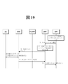
図11は、従来技術によりMA PDUセッションの結合確立手順を例示的に示す例示図である。 FIG. 11 is an exemplary diagram illustrating an exemplary procedure for establishing a bond in a MA PDU session using prior art.
図11の結合確立手順は、UEが要求するMA PDUセッション確立手順を示す。2つのチャイルドPDUセッション確立手順は、相異なるPDUセッションIDを有する。図9に示す例示において3GPPアクセス上でのチャイルドPDUセッションはPDUセッションID−1と示されており、非3GPPアクセス上でのチャイルドPDUセッションはPDUセッションID−2と示されている。5GCのSMFは、2つのN2 PDUセッション確立手順をトリガする。UEは、PDUセッションID−1に対するPDUセッション確立受諾メッセージを3GPPアクセスを介して受信し、PDUセッションID−2に対するPDUセッション確立受諾メッセージを非3GPPアクセスを介して受信することができる。前記SMFは、同一のUPFを経由する2つのPDUセッションを全てアンカリングし、前記2つのPDUセッションに同一のIPアドレスを割り当てることができる。 The connection establishment procedure of FIG. 11 shows the MA PDU session establishment procedure requested by the UE. The two child PDU session establishment procedures have different PDU session IDs. In the example shown in FIG. 9, the child PDU session on the 3GPP access is shown as PDU session ID-1, and the child PDU session on the non-3GPP access is shown as PDU session ID-2. The 5GC SMF triggers two N2 PDU session establishment procedures. The UE can receive the PDU session establishment acceptance message for PDU session ID-1 via 3GPP access and the PDU session establishment acceptance message for PDU session ID-2 via non-3GPP access. The SMF can anchor all two PDU sessions via the same UPF and assign the same IP address to the two PDU sessions.
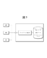
<本明細書の開示により解決しようとする問題点> <Problems to be solved by disclosure of this specification>
I.第1問題点 I. First problem
EPS(Evolved Packet System)において提案されたNBIFOM(Network−Based IP Flow Mobility)によると、NBIFOM規則をアップデートする場合、端末又はネットワークは、規則をアップデートすると同時に、QoS(Quality of Service)情報をアップデートすることができる。また、NBIFOM規則は、端末又はネットワークが一方的に規則を適用するのではなく、互いに確認した上で適用を開始する。 According to NBIFM (Network-Based IP Flow Mobility) proposed in EPS (Evolved Packet System), when updating NBIFM rules, the terminal or network updates the rules and at the same time updates the QoS (Quality of Service). be able to. Further, the NBIFM rule is not applied unilaterally by the terminal or the network, but the application is started after confirming each other.
従って、端末/ネットワークがNBIFOM規則とQoS情報を同時にアップデートするためのシグナリングを送信する場合、端末又はネットワークが規則を受諾しないと、不要なQoS情報をアップデートする動作を行うことになる。例えば、端末がMA(multi−access) PDUセッションを有している状況でSMFが非3GPPアクセスに送信されるIPフロー(flow)♯1を3GPPアクセスに移したい場合、3GPPアクセスを介してATSSS(Access Traffic Steering,Switching and Splitting)規則を送信すると同時にIPフロー♯1のためのQoSフローセットアップを行うことができる。この場合、ATSSS規則が端末により拒絶されると、IPフロー♯1は継続して非3GPPアクセスに送信される状況であるが、不要に3GPPアクセスにIPフロー♯1のためのQoSフローを生成する状況が発生する。
Therefore, when the terminal / network transmits a signaling for updating the NBIFM rule and the QoS information at the same time, if the terminal or the network does not accept the rule, the operation of updating unnecessary QoS information will be performed. For example, if the terminal has an MA (multi-access) PDU session and the SMF wants to transfer the IP flow (flow) # 1 transmitted to the non-3GPP access to the 3GPP access, ATTSS (ATSSS) via the 3GPP access. Access Traffic Steering, Switching and Splitting) Rules can be sent and at the same time a QoS flow setup for
また、ATSSS規則を受諾したが、反映式(Reflective)QoSを使用する場合には、ダウンリンクパケットよりアップリンクパケットが先に発生する場合は、当該アップリンクパケットにQoSを適用できないという問題が発生する。また、3GPPアクセスには、反映式QoSを適用するためにはRANにRQA(Reflective QoS Attribute)を送信してSDAP(Service Data Adaptation Protocol)ヘッダを使用するようにしなければならないが、3GPPアクセスにフローを移す場合は、ダウンリンクパケットが先に発生してもRANにRQAを送信していないと、反映式QoSを適用することができない。また、RQAをATSSS規則のアップデートに送信し、UEがATSSS規則を拒絶する場合、不要にRANにおいてSDAPヘッダを使用するため、リソース浪費が発生することがある。また、UEがATSSS規則をアップデートする場合は、RANにRQAのための別途のシグナリングを送らなければならないという問題点がある。 In addition, if the ATSSS rule is accepted but the uplink packet is generated before the downlink packet when using Reflective QoS, there is a problem that QoS cannot be applied to the uplink packet. do. In addition, for 3GPP access, in order to apply reflected quality of service, it is necessary to send RQA (Reflective Quality of Service) to RAN and use SDAP (Service Data Adapter) header, but it flows to 3GPP access. In the case of transferring, the reflection type QoS cannot be applied unless the RQA is transmitted to the RAN even if the downlink packet is generated first. Also, if the RQA is sent to an ATSSS rule update and the UE rejects the ATSSS rule, resource waste may occur because the SDAP header is unnecessarily used in the RAN. There is also the problem that if the UE updates the ATSSS rules, it must send a separate signaling for the RQA to the RAN.
II.第2問題点 II. Second problem
5GSにおいてQoSはAN(Access Network)のQoSとCN(Core Network)のQoSが分離されている。CNにおいては、N3ヘッダにあるQFI(QoS Flow ID)に基づいてQoS差別化(differentiation)が行われ、同一のQFIは同一のQoS処理を受信することができる。このとき、同一のQFI(すなわち、同一のQoS処理)を有するフローをQoSフローといい、それぞれのQoSフローはANにおいて無線リソースにマッピングされてANにおけるQoS処理が可能になっている。このとき、ANにおいてQoSフローをANリソース(例えば、ラジオベアラ、IPsecトンネル)にマッピングする方法は決まっておらず、ANの実現として残されている。複数のQoSフローは、1つのANリソースにマッピングが可能である。このようなマッピング情報は、AN特定シグナリング(例えば、RRC接続再設定(Reconfiguration)、IKEシグナリング)を介して端末に送信される。もし、マッピング情報のないQoSフローがある場合には、基本ANリソース(例えば、基本ラジオベアラ)で送信される。端末は、QoS規則に基づいて発生したトラフィックをどのようなQoSフローに送信すべきであるかを決定する。 In 5GS, the QoS of AN (Access Network) and the QoS of CN (Core Network) are separated. In CN, QoS differentiation is performed based on QFI (QuoS Flow ID) in the N3 header, and the same QFI can receive the same QoS processing. At this time, a flow having the same QFI (that is, the same QoS processing) is called a QoS flow, and each QoS flow is mapped to a radio resource in the AN so that the QoS processing in the AN is possible. At this time, the method of mapping the QoS flow to the AN resource (for example, radio bearer, IPsec tunnel) in AN has not been decided, and it is left as the realization of AN. Multiple QoS flows can be mapped to one AN resource. Such mapping information is transmitted to the terminal via AN specific signaling (eg, RRC connection reconfiguration, IKE signaling). If there is a QoS flow without mapping information, it is transmitted by the basic AN resource (for example, the basic radio bearer). The terminal determines to what QoS flow the traffic generated under the QoS rules should be sent.
端末は、遊休(Idle)状態から接続(CONNECTED)状態に進入するとき、全てのQoSフローにマッピングされるANリソースが全て生成される。従って、QoS規則があり、接続状態にある場合は、端末は、ANリソースが全てセットアップされていると考え、特別なシグナリングなしにトラフィックを送信する可能性がある。 When the terminal enters the Connected state from the idle state, all AN resources mapped to all QoS flows are generated. Therefore, if there is a QoS rule and is in a connected state, the terminal may assume that all AN resources have been set up and send traffic without any special signaling.
しかしながら、MA−PDUセッションの場合は、従来のQoSフレームワークがうまく動作しない。 However, in the case of MA-PDU sessions, the traditional QoS framework does not work well.
MA−PDUセッションは、ステアリング(steering)規則により一方のアクセスのデータフローが他方のアクセスに移ることがある。この場合、端末は、マッピング情報がない場合、基本(default)ANリソースを介して送信するので、自分の有しているQoS規則にマッピングされているANリソースがセットアップされているか否かが分かる。 In a MA-PDU session, the data flow of one access may be transferred to the other access due to steering rules. In this case, since the terminal transmits via the default AN resource when there is no mapping information, it is possible to know whether or not the AN resource mapped to the QoS rule possessed by the terminal is set up.
<本明細書の開示> <Disclosure of the present specification>
本明細書の第1開示は、前述した第1問題点を解決するための方案を提示する。そして、本明細書の第2開示は、前述した第2問題点を解決するための方案を提示する。 The first disclosure of the present specification presents a plan for solving the above-mentioned first problem. The second disclosure of the present specification presents a plan for solving the above-mentioned second problem.
I.第1開示 I. First disclosure
I−1.第1開示の第1方案:両方のアクセスに常に同一のQoSフローを生成しておく方案 I-1. First disclosure first: A way to always generate the same QoS flow for both accesses
第1方案は、ATSSSを適用するPDUセッションの場合、常に両方のアクセスに同一のQoSフローを生成しておく方案である。このようにすると、QoSフローをアップデートする過程なしにATSSS規則アップデートのみでトラフィックを処理することができる。しかしながら、このような方案を使う場合、実際のトラフィックは一方にのみ行くことがあるので、端末、ネットワークのリソースを効率的に使えない可能性がある(GBR(Guaranteed Bit Rate) QoSフローの場合、ラジオリソースを使用しなければならないので、使用が難しい)。また、3GPPアクセスにおいては反映式QoSを使用するためにSDAPヘッダを使用すべきであるが、これは追加的なラジオリソースを使用しなければならないという問題がある。特に、反映式QoSを適用するQoSフローの場合、一定時間の間ダウンリンクパケットがないと、反映式QoSタイマが満了して反映式QoS規則が削除されるので、これを維持するための方法が必要である。すなわち、一方のアクセスにおいて反映式QoSを使用する場合、他方のアクセスには反映式QoSではなく明白なQoS規則を下して管理しなければならないという問題が発生する。しかしながら、QoSフローが頻繁に移動しなければならないか、1つのQoSフローが複数のIPフローと共に使用されてほとんど常に使用されるQoSフローであると(例えば、基本(default)QoSフローが3GPP、非3GPPアクセスにおいて同一のQFIを使用する場合)、このような方案を使用して簡単にQoSを保障することができる。 The first plan is to always generate the same QoS flow for both accesses in the case of a PDU session to which ATSSS is applied. In this way, the traffic can be processed only by the ATSSS rule update without the process of updating the QoS flow. However, when using such a plan, the actual traffic may go to only one side, so there is a possibility that the resources of the terminal and network cannot be used efficiently (in the case of GBR (Guaranteed Bit Rate) QoS flow). Difficult to use because you have to use radio resources). Also, in 3GPP access, the SDAP header should be used to use reflected QoS, but this has the problem of having to use additional radio resources. In particular, in the case of a QoS flow to which the reflected QoS is applied, if there is no downlink packet for a certain period of time, the reflected QoS timer expires and the reflected QoS rule is deleted. is necessary. That is, when the reflected QoS is used for one access, there arises a problem that the other access must be managed under an explicit QoS rule instead of the reflected QoS rule. However, if the QoS flow must move frequently or if one QoS flow is used with multiple IP flows and is almost always used (eg, the default QoS flow is 3GPP, non-). If the same QFI is used for 3GPP access), such a scheme can be used to easily guarantee QoS.
I−2.第1開示の第2方案:ATSSS規則アップデート後に別途の規則を適用せよとのインジケーションを送信する方案 I-2. Second plan of the first disclosure: A plan to send an indication to apply another rule after the ATSSS rule update.
第2方案は、ATSSSの規則を更新した後、別途のシグナリングを介して端末/ネットワークがQoSフローに対するセットアップを行い、以後、別途のシグナリングを送ってATSSS規則を適用する方案である。このような方案は明白なQoS規則や反映式(Reflective)QoSの両方ともに適用が可能な方法である。 The second plan is to update the ATSSS rules, then set up the terminal / network for the QoS flow via a separate signaling, and then send a separate signaling to apply the ATSSS rules. Such a scheme is a method that can be applied to both explicit QoS rules and Reflective QoS.
図12は、第1開示の第2方案を示す例示的な信号流れ図である。 FIG. 12 is an exemplary signal flow diagram showing the second aspect of the first disclosure.
図12に示すように、ATSSSの規則をアップデートするためのシグナリング、QoSフローを設定するためのシグナリング、ATSSS規則を適用するためのシグナリングがそれぞれ送信される。このように、各シグナルがそれぞれ別々に送信されるので、シグナリングに対するオーバーヘッドが増加する可能性がある。この方案を使用する場合、QoSフローをセットアップするシグナリングとATSSS規則を適用せよとのシグナリングは、1つのプロシージャを使用することもできる。例えば、図12において過程3は過程2とともに行われることができる。
As shown in FIG. 12, signaling for updating ATSSS rules, signaling for setting QoS flows, and signaling for applying ATSSS rules are transmitted, respectively. In this way, each signal is transmitted separately, which can increase the overhead for signaling. When using this strategy, a single procedure can also be used for signaling to set up QoS flows and to apply ATSSS rules. For example, in FIG. 12,
I−3.第1開示の第3方案:ATSSS規則アップデートプロシージャのうちQoSアップデートのためのプロシージャを行う方案 I-3. Third method of the first disclosure: A method of performing a procedure for QoS update among the ATSSS rule update procedures.
この方案は、ATSSS規則をアップデートするプロシージャ中に端末/ネットワークがATSSS規則を受諾する場合、QoS規則をアップデートする別途のプロシージャを行い、QoS規則アップデートが終わると、ATSSS規則をアップデートするプロシージャを再び行う方案である。 This alternative takes a separate procedure to update the QoS rule if the terminal / network accepts the ATSSS rule during the procedure to update the ATSSS rule, and again the procedure to update the ATSSS rule after the QoS rule update is complete. It is a plan.
図13は、第1開示の第3方案による、ATSSS規則更新手順の第1例示を示す信号流れ図である。 FIG. 13 is a signal flow diagram showing a first example of the ATSSS rule update procedure according to the third aspect of the first disclosure.
図13から分かるように、過程1において端末(すなわち、UEとして示す)は、更新しようとするATSSS規則を含むメッセージを送信する。ネットワークにおいてATSSS規則を受諾する場合、ネットワークは、直ちに過程1に対する応答メッセージを送信せずに、アップデートされるATSSS規則のための新しいQoSフローセットアップのために新しいSMプロシージャ(過程2ないし過程3)を開始する。QoSフローセットアップが終わった後、ネットワークは過程1に対する応答メッセージを過程4で送信し、そして、アップデートされたATSSS規則の適用を開始する。端末も課程4においてメッセージを受信した後にこれに対する応答メッセージを送信した後、ATSSS規則の適用を開始する。もし、ネットワークにおいてATSSS規則を拒絶する場合、過程2ないし過程5は省略され、直ちに過程1に対する応答メッセージである過程6を送るとともにATSSS規則を拒絶したことを知らせる。
As can be seen from FIG. 13, in
このシナリオにおいて、過程2は過程4とともに、過程3は過程5とともに行われることにより、別途のプロシージャなしに一度のプロシージャで行われるようにすることもできる。
In this scenario,
図14は、第1開示の第3方案による、ATSSS規則更新手順の第2の例示を示す信号流れ図である。 FIG. 14 is a signal flow diagram illustrating a second example of the ATSSS rule update procedure according to the third aspect of the first disclosure.
ネットワークにおいて開始するATSSS規則更新手順は、図14に示すように行われることができる。図14に示す過程1において、ネットワークは更新しようとするATSSS規則を含むメッセージを送信することができる。端末(すなわち、図示されたUE)がATSSS規則を受諾する場合、ネットワークに直ちに過程1に対する応答を送らずにアップデートされたATSSS規則のための新しいQoSフローセットアップを要求する新しいSMプロシージャ(すなわち、過程2ないし過程4)を開始する。QoSフローセットアップが終わった後、端末は、過程1に対する応答メッセージを過程5で送信し、アップデートされたATSSS規則の適用を開始する。ネットワークも過程5を受信した後、ATSSS規則の適用を開始する。もし、端末においてATSSS規則を拒絶する場合、過程2ないし過程5は省略され、直ちに過程1に対する応答メッセージである過程6を送るとともにATSSS規則を拒絶したことを知らせる。
The ATSSS rule update procedure initiated in the network can be performed as shown in FIG. In
一方、反映式QoSを使用する場合、ネットワークはQoSフローをセットアップする過程で、3GPPアクセスにおいても継続して反映式QoSを使用しようとする場合は、RQAをRANに送信しなければならない。例えば、図13の過程2、図14の過程3でRQAをRANに送信することができる。
On the other hand, when using reflected QoS, the network must send an RQA to the RAN if it intends to continue using reflected QoS in 3GPP access in the process of setting up the QoS flow. For example, the RQA can be transmitted to the RAN in the
もし、反映式QoSのみを使用するか、明示的なQoS規則アップデートが必要ない場合、端末/ネットワークは、追加的なQoSフローセットアップのための手順(例えば、図13の過程2ないし過程3、図14の過程2ないし過程4)を行わないことがあり得る。このような場合は、反映式QoSを使用するためのRQAをRANに送信するだけのために当該プロシージャを使用することもできるが、次のような方案によりシグナリングを低減することができる。
If only reflective QoS is used or no explicit QoS rule update is required, the terminal / network will have procedures for additional QoS flow setup (eg, steps 2 or 3 of FIG. 13, FIG. It is possible that
図15は、第1開示の第3方案による、ATSSS規則更新手順の第3例示を示す信号流れ図である。 FIG. 15 is a signal flow diagram showing a third example of the ATSSS rule update procedure according to the third aspect of the first disclosure.
図14に示すように、端末がATSSS規則をアップデートする場合、ネットワークがATSSS規則を受諾すると、過程2で端末にATSSS規則を受諾すると知らせるとともに、追加的に反映式QoSを継続して使用せよとのインジケーションを送信する。端末は、前記インジケーションを受信した場合、過程4においてのようにRANとASシグナリングを利用してATSSS規則により影響を受信するQoSフローに対して反映式QoSが使用されることを知らせる。この過程は、過程3と同時に行われるか、又は先に行われることもできる。また、端末は、このようなインジケーションを受信した場合、以前のアクセスにおいて使用する反映式QoSにより生成された、誘導(derived)QoS規則がそのまま移るアクセスにおいても使用できるようにする。また、端末は、以前のアクセスにおいてはATSSS規則により移されるフローに対する反映式QoSのための動作(誘導QoS規則のためのタイマを維持する動作)を行わずに反映式QoSタイマを止めて誘導(derived)QoS規則を消すことができる(実際にトラフィックが移った後に動作しなければならない)。このシナリオにおいて、ネットワークは端末にインジケーションを送信するのではなく、直接RANにRQAを送ることによりQoSフローに反映式(Reflective)QoSが使われることを知らせることもできる。
As shown in FIG. 14, when the terminal updates the ATSSS rule, if the network accepts the ATSSS rule, it informs the terminal that it accepts the ATSSS rule in
図16は、第1開示の第3方案による、ATSSS規則更新手順の第4例示を示す信号流れ図である。 FIG. 16 is a signal flow diagram showing a fourth example of the ATSSS rule update procedure according to the third aspect of the first disclosure.
図15に示すように、ネットワークがATSSSの規則をアップデートする場合、ネットワークは、過程1で更新されたATSSS規則を下しながら継続して反映式QoSを使用せよとのインジケーションを追加で送る。これを受信した端末は、ネットワークが送ったATSSS規則を受諾する場合にのみRANとASシグナリングを介してATSSS規則により影響を受信するQoSフローに対して反映式QoSが使用されることを知らせる。この過程は、過程2と同時に行われるか、先に行われることもできる。また、端末は、このようなインジケーションを受信した後、当該ATSSS規則を受諾すると決定した場合、以前のアクセスにおいて使用する反映式QoSにより生成された誘導QoS規則がそのまま移るアクセスにおいても使用できるようにする。また、端末は、以前のアクセスにおいてはATSSS規則により移されるフローに対する反映式QoSのための動作(誘導QoS規則のためのタイマを維持する動作)を行わずに反映式QoSタイマを止めて誘導されたQoS規則を消すことができる(実際にトラフィックが移って以後に動作しなければならない)。
As shown in FIG. 15, when the network updates the ATSSS rules, the network additionally sends an indication to continue to use the reflected QoS rules while violating the ATSSS rules updated in
I-4.第1開示の第4方案:ATSSS規則アップデート以後にQoSをアップデートする方案 I-4. Fourth plan of the first disclosure: A plan to update QoS after the ATSSS rule update
第4方案は、ATSSSの規則をアップデートした以後にQoSをアップデートする方案である。この方案は、特別な追加動作なしに動作するため、別途のプロシージャを行う必要がない。また、第1方案のように予めリソースを予約して使用しない。しかしながら、ATSSS規則がアップデートされた後、QoSをアップデートするまでの一定時間の間は、QoSを満足できないトラフィックが発生する場合がある。特に、GBRフローや遅延に敏感な(delay critical)フローなどはQoS管理に問題が発生する可能性がある。従って、このような方案は、当該ATSSS規則によって移されるフローが非GBRフローのように特別なQoS処理が必要でないフローである場合に使用することができる。 The fourth plan is to update QoS after updating the rules of ATSSS. This plan works without any additional action, so no separate procedure is required. Also, unlike the first plan, resources are reserved and not used in advance. However, there may be traffic that does not satisfy QoS for a certain period of time after the ATSSS rules are updated until the QoS is updated. In particular, GBR flows and delay critical flows can cause problems in QoS management. Therefore, such an alternative can be used when the flow transferred by the ATSSS rule is a flow that does not require special QoS processing, such as a non-GBR flow.
II.第2開示 II. Second disclosure
本明細書の第2開示は、前述した第2問題点を解決するために方案を提示する。 The second disclosure of the present specification presents a plan for solving the above-mentioned second problem.
第2開示において、ステアリング規則は、ATSSS規則と解釈されることがあり、互いに混用して使用されることもある。第2開示において、3GPPアクセスと非3GPPアクセスの間に移動するデータフローは、トラフィック、QoSフローと解釈されることがあり、互いに混用して使用されることもできる。第2開示において、ステアリング(又は、トラフィックステアリング)は、スイッチング(又は、トラフィックスイッチング)及び分離(splitting)(又は、トラフィック分離)を含むと解釈されることができる。 In the second disclosure, the steering rules may be construed as ATSSS rules and may be mixed with each other. In the second disclosure, the data flow moving between 3GPP access and non-3GPP access may be interpreted as traffic, QoS flow, and may be used in combination with each other. In the second disclosure, steering (or traffic steering) can be interpreted as including switching (or traffic switching) and splitting (or traffic separation).
II−1.第2開示の第1方案:それぞれのアクセス別にQoS規則を別々に使用する方案 II-1. Second Disclosure First Plan: A plan to use QoS rules separately for each access
この方案は、SMFがMA−PDUセッションに対してそれぞれのアクセスに対するQoS規則を下す方案である。この方案の場合、あるアクセスに対するQoS規則がある場合、これに必要なANリソースもともにセットアップされている。従って、端末は、ステアリング規則により一方のアクセスから他方のアクセスにデータフローを移すとき、ソースアクセスにおいて使用したQFIと同一のQFIを有するQoS規則がターゲットアクセスにおいて存在する場合、SMFにシグナリングなしにデータフローを移す。もし、同一のQFIを有するQoS規則がない場合は、SMFにPDUセッション修正手順を介してソースアクセスと同一のQFIを有するQoS規則を要求する。この方案の場合、それぞれのアクセス別にQoS規則を送るため、同一のデータフローに対してもアクセス別に相異なるQoSフローを使用することができるという利点がある。このようにするためには、端末が同一のQFIを有するQoS規則を探すのではなく、移そうとするデータフローに対するパケットフィルタを含むQoS規則があるか否かをチェックする必要がある。ただし、この過程でソースアクセスにおけるQoSが基本(default)QoS規則にマッピングされるのでないと、ターゲットアクセスにおいても基本(default)QoS規則を除いて移そうとするデータフローが含まれたパケットフィルタを有するQoS規則があるか否かを探す。しかしながら、端末とネットワークの両方ともアクセス別にQoS規則を管理しなければならないので、シグナリングが増加し、最大に使用できるQoS規則の数字も減少するという問題がある。 This plan is for the SMF to impose QoS rules for each access to the MA-PDU session. In this case, if there is a QoS rule for a given access, the AN resources required for it are also set up. Thus, when a terminal shifts a data flow from one access to the other by steering rules, if there is a QoS rule in the target access that has the same QoS as the QFI used in the source access, then the data without signaling to the SMF. Move the flow. If there is no QoS rule with the same QFI, request the SMF a QoS rule with the same QFI as the source access via the PDU session modification procedure. In the case of this plan, since the QoS rule is sent for each access, there is an advantage that different QoS flows can be used for each access even for the same data flow. In order to do so, it is necessary to check whether there is a QoS rule including a packet filter for the data flow to be transferred, instead of searching for a QoS rule in which the terminal has the same QFI. However, unless the QoS in source access is mapped to the default QoS rule in this process, the packet filter that includes the data flow to be transferred except for the default QoS rule in the target access is also used. Find out if there is a QoS rule that you have. However, since both terminals and networks must manage QoS rules for each access, there is a problem that signaling increases and the number of QoS rules that can be used at the maximum decreases.
この場合、端末は、あるデータフローを移すとき、当該データフローをネットワークで望まないQoSフローを使用して移すという問題が発生する可能性がある。例えば、データフローが非3GPPアクセスにおいてGBR QoSフローを使用している場合、長い間3GPPアクセスにデータがないと、端末は、3GPPアクセスにおいてCM−IDLEになり得る。この場合、ネットワークにおいては3GPPアクセスにあるGBR QoSフローを解除することができ、これは、当該GBR QoSフローに接続されている端末のQoS規則を消す結果をもたらす。この場合、データフローを3GPPアクセスに移す必要があるとき、端末は、GBR QoSフローに対するQoS規則がないので、基本(default)QoS規則や他のQoS規則を利用して当該データフローを送信するようになる。これは、ネットワークにおいて意図しない結果であり、当該データフローのQoSを保障できなくなる。従って、端末は、トラフィックを移す前にSMFにシグナリングを送って、当該データフローを移す必要があることを知らせなければならない。これを受信したSMFは、新しいQoS規則を端末に下すか否かを判断することができ、必要な場合はQoS規則を下すことができる。このとき、後述する第2方案のPDUセッション修正手順やユーザプレーンに特別なトラフィックを送ることによりSMFに知らせることができる。 In this case, when the terminal transfers a certain data flow, there may be a problem that the data flow is transferred by using an unwanted QoS flow in the network. For example, if the data flow uses a GBR QoS flow in a non-3GPP access, the terminal can become a CM-IDLE in the 3GPP access if there is no data in the 3GPP access for a long time. In this case, the GBR QoS flow in the 3GPP access can be canceled in the network, which results in erasing the QoS rules of the terminal connected to the GBR QoS flow. In this case, when it is necessary to transfer the data flow to 3GPP access, the terminal should use the default QoS rule or other QoS rule to transmit the data flow because there is no QoS rule for the GBR QoS flow. become. This is an unintended result in the network, and the QoS of the data flow cannot be guaranteed. Therefore, the terminal must signal the SMF before moving the traffic to inform it that the data flow needs to be moved. Upon receiving this, the SMF can determine whether or not to impose a new QoS rule on the terminal, and if necessary, can impose a QoS rule. At this time, the SMF can be notified by sending a special traffic to the PDU session modification procedure of the second plan described later or the user plane.
II−2.第2開示の第2方案:全てのアクセスに対して共通QoS規則を使用する方案 II-2. Second Disclosure Second Plan: A Plan to Use Common QoS Rules for All Access
この方案は、QoS規則を全てのアクセスに対して同一に使用する方案である。このために、SMFがQoS規則を送信すると同時に、どのアクセスに対するANリソースがセットアップされているかを共に知らせることができる。もし、ステアリング規則により他のアクセスにデータフローを移そうとするとき、ターゲットアクセスにANリソースがセットアップされていない場合、SMFにPDUセッション修正手順を介してステアリングするというインジケーションを送信する。これを受信したSMFは、N2セットアップメッセージをANに送ってANリソースがセットアップされるようにすることができる。この過程で、端末にPDUセッション命令にステアリングが可能であることを知らせるインジケーションを含めて送信することができる。端末は、SMFからPDUセッション修正要求に対する応答を受信した後、または、ステアリングが可能であるとのインジケーションが含まれたPDUセッション修正要求に対する応答を受信した後、ターゲットアクセスにデータフローを送信する。 This strategy is to use the QoS rules the same for all accesses. For this, the SMF can send a QoS rule and at the same time inform which access the AN resource is set up for. If the steering rule attempts to transfer the data flow to another access and the AN resource is not set up for the target access, it sends an instruction to the SMF to steer via the PDU session modification procedure. Upon receiving this, the SMF can send an N2 setup message to the AN so that the AN resource is set up. In this process, the PDU session command can be transmitted to the terminal including an indication that steering is possible. The terminal sends the data flow to the target access after receiving the response to the PDU session modification request from the SMF or after receiving the response to the PDU session modification request containing the indication that steering is possible. ..
この方案をSMFが特定QoS規則に対してどのアクセスに対するANリソースがセットアップされているかを知らせずにnon−GBR QoSフローに対しては両方のアクセスに常にANリソースをセットアップし、GBR QoSフローに対してのみ現在使用中のアクセスに対してANリソースをセットアップすることができる(もし、両方とも使用中であると、両方のアクセスともにANリソースセットアップ可能)。この場合、端末は、non−GBR QoSフローに対してはSMFにシグナリングなしに直ちに他のアクセスにステアリングすることができる。GBR QoSフローの場合は、PDUセッション修正手順を介してステアリングをするというインジケーションをネットワークに送信した後、PDUセッション修正命令を受信する場合又はステアリングが可能であることを知らせるインジケーションが含まれたPDUセッション修正命令を受信する場合、データフローを他方のアクセスにステアリングすることができる。 This strategy always sets up AN resources for both accesses for non-GBR QoS flows without the SMF notifying which access the AN resources are set up for a particular QoS rule, and for GBR QoS flows. You can only set up AN resources for the access that is currently in use (if both are in use, you can set up AN resources for both accesses). In this case, the terminal can immediately steer other access to the non-GBR QoS flow without signaling to the SMF. In the case of the GBR QoS flow, after sending the instruction to steer through the PDU session correction procedure to the network, the instruction to receive the PDU session correction command or to inform that steering is possible was included. When receiving a PDU session modification instruction, the data flow can be steered to the other access.
方案2に対する例示として端末が非3GPPアクセスのGBRフローにある一部のデータフローを3GPPアクセスに移すことを仮定すると、次のように動作することができる。
As an example for
図17は、第2開示の第2方案による、PDUセッションに修正手順を示す例示図である。 FIG. 17 is an exemplary diagram showing a modification procedure for a PDU session according to the second aspect of the second disclosure.
図17に示す端末(すなわち、図示されたUE)は、5GSにMA−PDUセッションを生成した状態であると仮定する。 It is assumed that the terminal shown in FIG. 17 (that is, the illustrated UE) is in a state where a MA-PDU session is generated in 5GS.
1)端末がステアリング規則に基づいて非3GPPにあるGBR QoSフローを3GPPアクセスに移したい場合、PDUセッション修正要求メッセージを端末がデータフローを移そうとする3GPPアクセスを介してSMFに送信する。このメッセージには、端末がステアリングを要求するというインディケーションと、どのQoSフローを移すかに関する情報(例えば、QFIあるいはパケットフィルタ情報によるフロー情報、QoS規則に対する識別(identity)情報、又はATSSSステアリング規則に対する識別(identity)情報)が含まれる。もし、当該PDUセッションの非3GPPにある全てのGBR QoSフローを3GPPアクセスに移したいと、UEは、前記のように個々のQoSフローに関する情報の代わりに全てのGBR QoSフローであることを示す情報(例えば、ALL、*など)を含めることもできる。 1) When the terminal wants to transfer the GBR QoS flow in the non-3GPP to the 3GPP access based on the steering rule, the PDU session correction request message is transmitted to the SMF via the 3GPP access where the terminal tries to transfer the data flow. This message includes an indication that the terminal requests steering and information about which QoS flow to transfer (eg, flow information by QFI or packet filter information, identity information for QoS rules, or ATSSS steering rules. Identification information) is included. If we want to transfer all GBR QoS flows in the non-3GPP of the PDU session to 3GPP access, the UE will indicate that it is all GBR QoS flows instead of the information about the individual QoS flows as described above. (For example, ALL, *, etc.) can also be included.
2)SMFは、端末が送った情報に基づいて3GPPアクセスに関連QoSフローに対するN2セットアップが行われていないと判断した場合(又は、3GPPアクセスにおいて関連QoSフローに対するN2セットアップが行われなければならないと判断した場合)、RANにN2セットアップメッセージを送信する。 2) If the SMF determines that the N2 setup for the related QoS flow is not performed for the 3GPP access based on the information sent by the terminal (or the N2 setup for the related QoS flow must be performed for the 3GPP access). (If determined), send an N2 setup message to the RAN.
3)このとき、3GPPアクセスを介してPDUセッション修正要求を受けたため、これに対する回答であるPDUセッション修正命令メッセージをともに送信する。このメッセージ内には、端末にステアリングを開始してもよいとのインジケーションが含まれることができる。もし、RANにおいて該当QoSフローに対するN2セットアップを受けることができない場合、従来技術によりN1メッセージが送信されない。従って、SMFは、当該N2メッセージに対する応答にある拒否原因に基づいて端末にQoS規則をアップデートするか、又はステアリング規則をアップデートすることができる。 3) At this time, since the PDU session correction request was received via the 3GPP access, the PDU session correction instruction message which is the answer to the request is transmitted together. The message may include an indication that the terminal may start steering. If the RAN cannot receive the N2 setup for the corresponding QoS flow, the prior art does not send the N1 message. Therefore, the SMF can update the QoS rules to the terminal or update the steering rules based on the rejection cause in the response to the N2 message.
RANにおいてQoSフローに対するN2セットアップが失敗する場合、N1メッセージを端末に伝達しないようにするためにSMFが直接的にインジケーションをN2セットアップに追加してN2セットアップが成功する場合にのみRANにとって端末にN1メッセージを送信するようにすることができる。 If the N2 setup for a QoS flow fails in the RAN, the SMF directly adds the indication to the N2 setup to prevent the N1 message from being delivered to the terminal, and only if the N2 setup succeeds is the terminal for the RAN. It is possible to send an N1 message.
4)RANにおいて成功裏にQoSフローがセットアップされると、ANシグナリングを介してQoSフローとANリソースのマッピング関係が送信される。これは、選択的な手順である。もし、ANリソースとQoSフローとのマッピング関係に変更がない場合(例えば、基本(default)ラジオベアラに当該QoSフローがマッピングされる場合)、マッピング情報はアップデートされない。また、RANは、SMFが送ったPDUセッション修正命令メッセージを端末に送る。前記端末は、前記メッセージを受信した後、非3GPPアクセスにあるデータフローを3GPPアクセスに移す。これは、前記過程3において記述したPDUセッション修正命令メッセージ内に含まれたステアリングを開始してもよいとのインジケーションに基づいたことでもあり得る。以後、端末は、PDUセッション修正命令メッセージに対する応答としてPDUセッション修正Ackメッセージを送信する。
4) When the QoS flow is successfully set up in RAN, the mapping relationship between the QoS flow and the AN resource is transmitted via AN signaling. This is an optional procedure. If there is no change in the mapping relationship between the AN resource and the QoS flow (eg, the QoS flow is mapped to the default radio bearer), the mapping information is not updated. In addition, the RAN sends a PDU session correction instruction message sent by the SMF to the terminal. After receiving the message, the terminal transfers the data flow in the non-3GPP access to the 3GPP access. This may also be based on the indication that the steering included in the PDU session correction instruction message described in
ダウンリンクの場合、UPFがSMFから受信したステアリング規則に基づいてアクセスを選択して送信を行うことができる。ダウンリンクとアップリンクが同一のアクセスに送信されるためには、SMFがステアリング規則を与えるときに同一のアクセスを使うようにするインジケーションを入れるか(例えば、反映式QoSと類似してダウンリンクを受信するアクセスにアップリンクデータを送信するようにする方案など)、UPFと端末に、整列(align)されているステアリング規則を与えて自然に同一のアクセスにステアリングされるようにすることができる。 In the case of downlink, the UPF can select access and transmit based on the steering rule received from the SMF. In order for the downlink and uplink to be sent to the same access, either include an indication that allows the SMF to use the same access when giving steering rules (eg, downlink similar to reflective QoS). (Such as a way to send uplink data to the access that receives the), the UPF and the terminal can be given steering rules that are aligned so that they are naturally steered to the same access. ..
5)SMFは、RANから成功裏にN2セットアップが行われたというメッセージを受信する。 5) The SMF receives a message from the RAN that the N2 setup was successful.
6−8)SMFは、端末に送信したステアリング規則に基づいてこれ以上非3GPPアクセスに対するGBR QoSフローが必要ないと判断する場合、非3GPPアクセスに対するユーザプレーンリソースを解除することができる。もし、当該GBR QoSフローが他のデータフローにより使用中である場合は、そのまま維持する。または、SMFが直接GBR QoSフローを解除せずにN3IWFにおいてGBR QoSフローの非活性化(inactivity)を検出して解除されるまで待つこともできる。 6-8) The SMF can release the user plane resource for non-3GPP access if it determines that no more GBR QoS flow is needed for non-3GPP access based on the steering rules transmitted to the terminal. If the GBR QoS flow is in use by another data flow, keep it as it is. Alternatively, it is possible to wait until the SMF detects the inactivation of the GBR QoS flow in the N3IWF and cancels it without directly canceling the GBR QoS flow.
9)SMFは、UPFにアップデートされたQoSフロー情報を提供する。この過程は、過程5の後、他の過程と平行(parallel)に行われることができる。
9) The SMF provides the updated QoS flow information to the UPF. This process can be performed parallel to other processes after
端末は、PDUセッション修正手順を行わずにユーザプレーンを介してSMFにスイッチングが必要であることを知らせることができる。例えば、ユーザプレーンに特別なトラフィックを送るか又はデータを送信するヘッダ部分に特定マーキングによりスイッチングが必要であることを知らせることができる。すなわち、3GPPアクセスにおいては、SDAPヘッダにマーキングにより知らせることができ、非3GPPアクセスにおいては、GREヘッダにマーキングにより知らせることができる。この場合、RAN又はN3IWFにおいてSDAP/GREヘッダにあるマーキング情報をN3ヘッダにマーキングする動作を行わなければならない。これを受信したUPFは、SMFにシグナリングを送って端末が当該データフローに対するスイッチングを要求することを知らせる。SMFは、ANリソースセットアップが必要である場合、N2セットアップ要求メッセージをANに送信する。ANリソースセットアップが成功裏に行われた場合、SMFは再びUPFにシグナリングを送り、UPFは再び端末にユーザプレーンを介して知らせる。この後、端末は、UPFからユーザプレーンにマーキング情報を受信するか、一定時間が経過してからスイッチングを開始することができる。 The terminal can inform the SMF that switching is necessary via the user plane without performing the PDU session correction procedure. For example, a header portion that sends special traffic to the user plane or sends data can be informed that switching is required by a specific marking. That is, in the case of 3GPP access, the SDAP header can be notified by marking, and in the non-3GPP access, the GRE header can be notified by marking. In this case, the operation of marking the marking information in the SDAP / GRE header in the N3 header in the RAN or N3IWF must be performed. Upon receiving this, the UPF sends a signal to the SMF to inform that the terminal requests switching to the data flow. The SMF sends an N2 setup request message to the AN if AN resource setup is required. If the AN resource setup is successful, the SMF again signals the UPF, which again informs the terminal via the user plane. After that, the terminal can receive the marking information from the UPF to the user plane or start switching after a certain period of time has elapsed.
II−3.第2開示の第3方案:共通QoS規則と非共通QoS規則をともに使用する方案 II-3. Second Disclosure Third Plan: A plan that uses both common QoS rules and non-common QoS rules
この方案は、Non−GBR QoSフローに対しては共通QoS規則を使用し、GBR QoSフローに対してはそれぞれのアクセス別のQoS規則を使用する方案である。この方案を使用する場合、端末は、Non−GBR QoSフローに対しては第2方案においてのと同様に、SMFにシグナリングを別途に送信することが必要なくステアリングをすることができる。 This plan uses common QoS rules for Non-GBR QoS flows and uses QoS rules for each access for GBR QoS flows. When using this method, the terminal can steer the Non-GBR QoS flow without the need to separately transmit signaling to the SMF as in the second method.
GBR QoSフローの場合は、端末がSMFにソースアクセスで使用するQoSと同一のQoSを要求するために、PDUセッション修正要求メッセージをターゲットアクセス側に送信してターゲットアクセスに同一のQoSを生成した後、ステアリングを行う。 In the case of GBR QoS flow, after the terminal sends a PDU session modification request message to the target access side to generate the same QoS for the target access in order to request the SMF the same QoS as the QoS used for the source access. , Steering.
前述した第1ないし第3方案において、端末がSMFにQoSフローセットアップを要求するPDUセッション修正要求メッセージを送信するとき、端末は移そうとするデータフローに関する情報をともに送信する。この情報は、移そうとするデータフローのQFIになることができ、又はパケットフィルタの形態で送信されることができる。もし、SMFがターゲットアクセスにソースアクセスと同一のQoSフローをセットアップできない場合は、当該データフローに対するステアリング規則をアップデートするか、QoSをアップデートすることができる。 In the first to third measures described above, when the terminal sends a PDU session modification request message requesting the QoS to set up the QoS flow, the terminal also sends information about the data flow to be transferred. This information can be the QFI of the data flow to be transferred, or can be transmitted in the form of a packet filter. If the SMF is unable to set up the same QoS flow for the target access as the source access, it can update the steering rules for that data flow or update the QoS.
前述した第1ないし第3方案において、端末がPDUセッション修正要求メッセージを送信するのではなく、ネットワークにおいて直接PDUセッション修正を行うことができる。このようにするためには、端末は、常にGBR QoSフローに対してはダウンリンクトラフィックを受信したアクセスと同一のアクセスにのみアップリンクトラフィックを送信しなければならない。すなわち、端末においてATSSS規則により直接アクセスを選択して送信を行うのではなく、ネットワークにおいて決定したアクセスにのみトラフィックを送信する。ネットワークにおいては、当該アクセスにGBR QoSフローに対するリソースが割り当てられているか常に把握しているので、GBR QoSフローがうまくセットアップされているアクセスを介してトラフィックを送信し、端末は当該アクセスに同一に送信を行う。このためには、端末が最初にGBR QoSフローを送信するときにどのアクセスに送信すべきであるかが分からないので、基本(default)アクセス値を定めなければならない。これはATSSS規則により端末に知られるか、又は、端末に予め設定されている値を使用することができる。また、ネットワークにおいてダウンリンクで送信するアクセスにトラフィックを送れという意味で、ATSSS規則に関する情報を与えるか、又は反映式QoSに類似してユーザプレーンのマーキングにより当該情報を伝達することができる。または、UPFと端末に、整列(align)されているステアリング規則を与えて自然に同一のアクセスにステアリングされるようにすることができる。 In the first to third measures described above, the terminal can directly modify the PDU session on the network instead of transmitting the PDU session modification request message. To do so, the terminal must always send uplink traffic to the GBR QoS flow only to the same access that received the downlink traffic. That is, instead of selecting and transmitting direct access according to the ATSSS rules at the terminal, traffic is transmitted only to the access determined in the network. Since the network always knows if the access is allocated resources for the GBR QoS flow, it sends traffic through the access where the GBR QoS flow is well set up and the terminal sends the same to the access. I do. For this purpose, the default access value must be determined because it is not known to which access the terminal should send the GBR QoS flow for the first time. This can be known to the terminal by ATSSS rules or can use values preset in the terminal. It can also provide information about ATTSS rules in the sense that traffic can be sent to access that is transmitted on the network, or can be transmitted by user plane marking similar to reflective QoS. Alternatively, the UPF and the terminal can be given an aligned steering rule so that they are naturally steered to the same access.
UPFにおいてSMFが送ったATSSS規則によりダウンリンクステアリングをするとき、UPFは、当該アクセスにGBR QoSフローがセットアップされているかが分からないため、SMFとの相互作用によりトラフィックスイッチングをしてもよいのかを確認しなければならない。このために、実際にトラフィックスイッチングをする前にN4修正手順を介してSMFに特定トラフィックに関する情報とともにアクセスを変更してもいいのかに対するインジケーションを送信する。SMFは、UPFから関連したメッセージを受信する場合、当該トラフィックに対するGBR QoSフローにラジオリソースがセットアップされているかを確認した後、トラフィックスイッチングが可能であるか否かをUPFに知らせる。もし、ラジオリソースがセットアップされていない場合、PDUセッション修正手順を利用して当該GBR QoSフローに対するラジオリソースセットアップを行う。もし、この過程が失敗すると、UPFにトラフィックスイッチングが不可能であることを知らせるインジケーション及び/又はアップデートされたATSSS規則を送ることができる。 When performing downlink steering according to the ATSSS rules sent by the SMF in the UPF, the UPF does not know whether the GBR QoS flow is set up for the access, so whether the traffic may be switched by interacting with the SMF. Must be confirmed. To this end, prior to the actual traffic switching, an indication is sent to the SMF via the N4 correction procedure as to whether the access may be changed along with information about the specific traffic. When the SMF receives a related message from the UPF, it confirms that the radio resource is set up in the GBR QoS flow for the traffic and then informs the UPF whether the traffic switching is possible. If the radio resource has not been set up, the radio resource is set up for the GBR QoS flow using the PDU session modification procedure. If this process fails, an indication and / or an updated ATSSS rule can be sent to the UPF informing them that traffic switching is not possible.
II−4.第2開示の整理 II-4. Arrangement of the second disclosure
以下、MA PDU セッションに対するQoSをサポートするための方策について説明する。 The measures for supporting QoS for MA PDU session will be described below.
QoSフローは、MA PDUセッションにおいてQoS差別化のための最小単位であり、QoSフローは特定アクセスと連係されていない場合もある。データフローが2つのアクセス間でステアリングされるとき、同一のQoSフローが使用されることができる。 A QoS flow is the smallest unit for QoS differentiation in a MA PDU session, and the QoS flow may not be linked to a specific access. The same QoS flow can be used when the data flow is steered between the two accesses.
MA PDU セッションが確立されるとき、SMFは端末にQoS規則を提供することができる。端末がQoS規則に基づいて、アップリンクユーザプレーントラフィックを分類及びマーキング、すなわち、アップリンクトラフィックをQoSフローに連係させることができる。前記QoS規則は、3GPP及び非3GPPアクセスのために共通に使用されることができ、QoS分類は、ATSSSステアリング規則と無関係であり得る。前記SMFは基本QoS規則を端末に提供することができる。 When the MA PDU session is established, the SMF can provide QoS rules to the terminal. Terminals can classify and mark uplink user plane traffic based on QoS rules, i.e., link uplink traffic to QoS flows. The QoS rules can be commonly used for 3GPP and non-3GPP access, and the QoS classification can be independent of the ATSSS steering rules. The SMF can provide basic QoS rules to the terminal.
MA PDUセッションが確立される場合、SMFは、PDR(Packet Detection Rule)をUPFに提供することができる。前記UPFは、前記PDRに基づいてダウンリンクユーザプレーントラフィックを分類及びマーキングすることができる。前記PDRは、3GPP及び非3GPPアクセスのために共通に使用されることができ、QoS分類はATSSSステアリング規則と無関係であり得る。 When an MA PDU session is established, the SMF can provide a PDR (Packet Detection Rule) to the UPF. The UPF can classify and mark downlink user plane traffic based on the PDR. The PDR can be commonly used for 3GPP and non-3GPP access, and QoS classification may be independent of ATSSS steering rules.
MA−PDUセッションが確立される場合、前記SMFは、QoSプロファイルをRANとN3IWFに提供することができる。前記QoSプロファイルに基づいて、前記RANとN3IWFは、QoSフローのためのリソース、例えば、ラジオベアラの確立、IPsec SA、QoSフローをANリソースにマッピングを行うことができる。リソース割り当ては、QoSフローのタイプ(すなわち、非GBR QoSフロー、GBR QoSフロー)と関係なく行われることができる。これは、3GPPアクセス及び非3GPPアクセスの間で動的トラフィックステアリングを可能にすることができる。 If a MA-PDU session is established, the SMF can provide QoS profiles to RAN and N3IWF. Based on the QoS profile, the RAN and N3IWF can map resources for QoS flows, such as establishing radio bearers, IPsec SA, QoS flows to AN resources. Resource allocation can be done regardless of the type of QoS flow (ie, non-GBR QoS flow, GBR QoS flow). It can enable dynamic traffic steering between 3GPP access and non-3GPP access.
個別PDUセッション確立手順を使用してMA PDUセッションが確立される場合、そして、SMFがPDUセッションの確立受諾メッセージを第2アクセスに送信する場合、SMFは、QoS規則を端末に提供しないことがある。この場合、SMFは、QoSフローに対するANリソースを確立するために(例えば、ラジオベアラの確立、IPsec SA、QoSフローをANリソースにマッピング)、QoSプロファイルをANに提供することができる。 If a MA PDU session is established using the individual PDU session establishment procedure, and if the SMF sends a PDU session establishment acceptance message to the second access, the SMF may not provide QoS rules to the terminal. .. In this case, the SMF can provide the QoS profile to the AN in order to establish an AN resource for the QoS flow (eg, establish a radio bearer, IPsec SA, mapping QoS flow to an AN resource).
以下、GBR QoSフローの管理について説明する。 Hereinafter, the management of the GBR QoS flow will be described.
GBR QoSフローが確立される場合、UEは、一アクセスにおいてCM−IDLE状態に進入する。例えば、3GPPアクセス上にトラフィックが存在しない場合、RANは、3GPPアクセス上で活動がないため、N2接続を解除要求することができる。次に、端末は、3GPPアクセスにCM−IDLE状態で進入する。さらに、端末が非3GPPアクセスカバレッジを外れる場合、非3GPPアクセスにおいてCM−Idle状態に進入する。このような場合、SMFは、GBR QoSフローを解除することなく、GBR QoSフローと関連したQoS規則及びPDRをアップデートしないことがある。端末がCM−CONNNECTED状態に進入する場合、SMFは、GBR QoSフローのためにANリソースの確立をANに要求することができる。 When a GBR QoS flow is established, the UE enters the CM-IDLE state in one access. For example, if there is no traffic on the 3GPP access, the RAN can request to disconnect the N2 connection because there is no activity on the 3GPP access. Next, the terminal enters the 3GPP access in the CM-IDLE state. Further, when the terminal deviates from the non-3GPP access coverage, it enters the CM-Idle state in the non-3GPP access. In such cases, the SMF may not update the QoS rules and PDR associated with the GBR QoS flow without canceling the GBR QoS flow. When the terminal enters the CM-CONNNECTED state, the SMF can request the AN to establish an AN resource for the GBR QoS flow.
以下、アップリンクGBR QoSフロー検証について説明する。 Hereinafter, the uplink GBR QoS flow verification will be described.
アクセスをスイッチングする前に、ANリソースの確立を保証するために、端末は、PDUセッション修正手順を行い、前記端末がGBR QoSフローを他のアクセスに送信することを知らせるインジケーションを送信する。または、PDUセッション修正手順の代わりに、ユーザプレーンに特別なトラフィックを送ってトラフィックスイッチングをすることをUPFに知らせることができる。UPFは、このような特別なトラフィックを受信した場合、これをSMFに知らせる。前記SMFが前記インジケーションを受信する場合、そして、前記GBR QoSフローのためのANリソースが確立されていない場合、前記SMFはGBR QoSフローのためのANリソースの確立をANに要求することができる。 Prior to switching access, to ensure the establishment of AN resources, the terminal performs a PDU session modification procedure and sends an indication that the terminal sends a GBR QoS flow to another access. Alternatively, instead of the PDU session modification procedure, the UPF can be informed that special traffic is sent to the user plane for traffic switching. The UPF notifies the SMF when it receives such special traffic. If the SMF receives the indication and the AN resource for the GBR QoS flow has not been established, the SMF may request the AN to establish an AN resource for the GBR QoS flow. ..
図18は、MA PDUセッションのためのPDUセッション修正手順を示す。 FIG. 18 shows a PDU session modification procedure for a MA PDU session.
端末は、非3GPPアクセス上でGBR QoSフローのデータフローを送信し、3GPPアクセス上ではCM−IDLE状態にある。 The terminal transmits the data flow of the GBR QoS flow on the non-3GPP access and is in the CM-IDLE state on the 3GPP access.
1)前記端末がGBR QoSフローのデータフローを3GPPアクセスに変更しようとする場合、前記端末は、スイッチングインジケーションを含むPDUセッション修正要求メッセージを送信する。前記端末は、CM−IDLE状態であるので、前記PDUセッション修正要求メッセージを送信する前に、サービス要求メッセージを先に送信することができる。前記端末は、前記3GPPアクセス上でPDUセッション修正要求メッセージを送信する。前記PDUセッション修正要求メッセージは、前記端末が移動させたいGBR QoSフローのものと同一のQoS情報を含む。従って、前記SMFは、どのQoSフローが3GPPアクセスに移動されるべきであるかが分かる。 1) When the terminal intends to change the data flow of the GBR QoS flow to 3GPP access, the terminal transmits a PDU session correction request message including a switching indication. Since the terminal is in the CM-IDLE state, the service request message can be transmitted first before the PDU session correction request message is transmitted. The terminal transmits a PDU session correction request message on the 3GPP access. The PDU session correction request message contains the same QoS information as that of the GBR QoS flow that the terminal wants to move. Therefore, the SMF knows which QoS flow should be moved to 3GPP access.
2)前記SMFは、前記受信した情報に基づいて、影響を受けるQoSフローを見つける。前記SMFは、前記QoSフローに対して要求されるRANリソースを確立するために、RANに要求メッセージを送信すると決定する。 2) The SMF finds the affected QoS flow based on the received information. The SMF determines to send a request message to the RAN to establish the required RAN resource for the QoS flow.
3)前記SMFは、前記RANにN2セットアップメッセージを送信する。前記SMFは、PDUセッション修正命令メッセージを前記N2セットアップメッセージ内に含ませる。また、前記SMFは、前記端末が3GPPアクセス上でデータフローを送信することを示すインジケーションを前記メッセージ内に含ませることができる。 3) The SMF transmits an N2 setup message to the RAN. The SMF includes a PDU session correction instruction message in the N2 setup message. Further, the SMF can include an indication in the message indicating that the terminal transmits a data flow on the 3GPP access.
4)前記RANは、ラジオリソース確立を行う。前記RANは、前記PDUセッション修正命令メッセージを前記端末に送信する。前記PDUセッション確立命令メッセージを受信すると、前記端末は、ステアリング規則に基づいてデータフローをスイッチングする。 4) The RAN establishes radio resources. The RAN transmits the PDU session correction instruction message to the terminal. Upon receiving the PDU session establishment command message, the terminal switches the data flow based on the steering rule.
5)前記RANは、N2セットアップ応答メッセージを送信する。前記RANが前記QoSフローの確立を拒絶する場合、前記SMFは、QoS規則及び/又はステアリング規則をアップデートする。 5) The RAN sends an N2 setup response message. If the RAN refuses to establish the QoS flow, the SMF updates the QoS and / or steering rules.
以下、ダウンリンクGBR QoSフロー検証について説明する The downlink GBR QoS flow verification will be described below.
ANリソースの確立を保証するために、アクセスをスイッチングする前に、UPFは、N4セッションレベルの報告手順を行う。そして、前記UPFは、前記GBR QoSフローを他のアクセスに送信することを知らせるインジケーションを送信する。前記SMFが前記インジケーションを受信する場合、そして、前記GBR QoSフローのためのANリソースがまだ確立されていない場合、前記SMFは、前記GBR QoSフローのためのANリソースの確立をANに要求することができる。 To ensure the establishment of AN resources, UPF performs N4 session level reporting procedures before switching access. Then, the UPF transmits an indication notifying that the GBR QoS flow is transmitted to another access. If the SMF receives the indication and the AN resource for the GBR QoS flow has not yet been established, the SMF requests the AN to establish an AN resource for the GBR QoS flow. be able to.
図19は、N4セッションレベルの報告手順を利用したダウンリンクGBR QoSフロー検証手順を示す信号流れ図である。 FIG. 19 is a signal flow diagram showing a downlink GBR QoS flow verification procedure using an N4 session level reporting procedure.
1)UPFがGBR QoSフローのデータフローを3GPPアクセスにスイッチングしようとする場合、前記UPFは、N4セッション報告手順を行いながら、スイッチングインジケーションを送信する。 1) When the UPF attempts to switch the data flow of the GBR QoS flow to 3GPP access, the UPF transmits a switching indication while performing the N4 session reporting procedure.
2)前記SMFは、前記受信した情報に基づいて、影響を受けるQoSフローを見つける。そして、対応するリソースがまだ割り当てられていない場合、前記SMFは、前記QoSフローのために必要なRANリソースの確立をRANに要求すると決定する。 2) The SMF finds the affected QoS flow based on the received information. Then, if the corresponding resource has not yet been allocated, the SMF determines that the RAN is required to establish the RAN resource required for the QoS flow.
3)前記SMFは、前記RANにN2セットアップメッセージを送信する。 3) The SMF transmits an N2 setup message to the RAN.
4)前記RANは、ラジオリソース確立手順を行い、応答メッセージをSMFに送信する。 4) The RAN performs a radio resource establishment procedure and sends a response message to the SMF.
5)前記SMFは、N4セッション報告Ackメッセージを送信し、UPFが3GPPアクセス上でデータフローを送信してもいいことを示すインジケーションを送信する。 5) The SMF sends an N4 session report Acck message and sends an indication indicating that the UPF may send a data flow over 3GPP access.
図20は、本明細書の一開示による方案を示す例示図である。 FIG. 20 is an exemplary diagram showing a plan according to one disclosure of the present specification.
図20に示すように、MA PDUセッション内のQoSフローがGBR QoSフローではないことに基づいて、SMFノードは、QoSプロファイルを3GPPアクセス及び非3GPPアクセスの両方ともに送信すると決定することができる。 As shown in FIG. 20, based on the fact that the QoS flow in the MA PDU session is not a GBR QoS flow, the SMF node can determine to send the QoS profile for both 3GPP access and non-3GPP access.
または、MA PDUセッション内のQoSフローがGBR QoSフローであることに基づいて、前記SMFノードは、QoSプロファイルを3GPPアクセス及び非3GPPアクセスのいずれか1つのアクセスに送信すると決定することができる。 Alternatively, based on the QoS flow in the MA PDU session being a GBR QoS flow, the SMF node can determine to send the QoS profile to any one of 3GPP access and non-3GPP access.
前記決定に基づいて、前記SMFノードは、前記QoSプロファイルを送信することができる。 Based on the determination, the SMF node can transmit the QoS profile.
前記SMFは、前記3GPPアクセス及び前記非3GPPアクセスのうち前記1つのアクセスを決定することができる。 The SMF can determine one of the 3GPP access and the non-3GPP access.
前記SMFは、前記MA PDUセッションが確立されることに基づいて、QoS規則をUE(user equipment)に送信することができる。 The SMF can transmit a quality of service (QoS rule) to a UE (user equation) based on the establishment of the MA PDU session.
前記QoS規則は、前記3GPPアクセス及び前記非3GPPアクセスの両方とものために共通的に使用されることができる。 The QoS rules can be commonly used for both the 3GPP access and the non-3GPP access.
前記MA PDUセッションは、前記3GPPアクセス及び前記非3GPPアクセスの両方ともにおいて確立されることができる。 The MA PDU session can be established in both the 3GPP access and the non-3GPP access.
ステアリング規則に従って前記GBR QoSフローを前記3GPPアクセス及び非3GPPアクセスのうち第1アクセスから第2アクセスに移動しなければならない場合、前記SMFは、UPFからスイッチングが必要であることを知らせるインジケーションを受信することができる。 If the GBR QoS flow must be moved from the first access to the second access of the 3GPP access and non-3GPP access according to the steering rules, the SMF receives an indication from the UPF that switching is required. can do.
前記インジケーションは、スイッチングしょうとするQoSフローに関する情報とスイッチングしようとする前記第2アクセスに関する情報を含む。 The indication includes information about the QoS flow to be switched and information about the second access to be switched.
前記SMFは、GBR QoSフローのスイッチングが成功裏に行われたことを前記UPFに知らせることができる。 The SMF can inform the UPF that the switching of the GBR QoS flow has been successful.
前記QoSプロファイルは、前記インジケーションに基づいて送信されることができる。 The QoS profile can be transmitted based on the indication.
前記GBR QoSフローが成功裏に行われたことを知らせるインジケーションは、前記UPFにとって前記第2アクセスへのスイッチングを行うことができる。 The indication indicating that the GBR QoS flow has been successfully performed can switch to the second access for the UPF.
前記QoSプロファイルが送信される1つのアクセスは、現在使用中のアクセスであり得る。前記QoSプロファイルは、前記現在使用中のアクセス上でリソースをセットアップするのに使用されることができる。 One access to which the QoS profile is transmitted may be the access currently in use. The QoS profile can be used to set up resources on the currently in-use access.
これまで説明した内容はハードウェアで実現されることができる。これについて図面を参照して説明する。 The contents described so far can be realized by hardware. This will be described with reference to the drawings.
図21は、本発明の実施形態による端末及びネットワークノードの構成ブロック図である。 FIG. 21 is a block diagram of a terminal and a network node according to an embodiment of the present invention.
図21に示すように、前記端末100は、メモリ101と、プロセッサ102と、送受信部103とを含む。そして、前記ネットワークノードは、AMF、SMF、NEF、及びAFのいずれか1つであり得る。前記ネットワークノードは、メモリ511と、プロセッサ512と、送受信部513とを含む。
As shown in FIG. 21, the terminal 100 includes a
前記メモリは、ROM(read−only memory)、RAM(random access memory)、フラッシュメモリ、メモリーカード、格納媒体及び/又は他の格納装置を含むことができる。 The memory may include a ROM (read-only memory), a RAM (random access memory), a flash memory, a memory card, a storage medium, and / or other storage devices.
前記メモリは、前述した方法を格納する。 The memory stores the method described above.
前記プロセッサは、ASIC(application−specific integrated circuit)、他のチップセット、論理回路及び/又はデータ処理装置を含むことができる。 The processor can include an ASIC (application-specific integrated circuit), other chipsets, logic circuits and / or data processing devices.
前記プロセッサは、前記メモリ及び前記送受信部を制御する。具体的に、前記プロセッサは、前記メモリに格納されている前記方法をそれぞれ実行する。そして、前記プロセッサは、前記送受信部を介して前述した信号を送信する。 The processor controls the memory and the transmission / reception unit. Specifically, the processor executes each of the methods stored in the memory. Then, the processor transmits the above-mentioned signal via the transmission / reception unit.
前記送受信部は、無線周波数信号を処理するための基底帯域回路を含むことができる。 The transmitter / receiver may include a baseband circuit for processing a radio frequency signal.
実施形態がソフトウェアで実現される場合、本明細書で説明された技術は、本明細書で説明された機能を行うモジュール(例えば、手順、機能など)で実現されることができる。モジュールは、メモリ101に格納されることができ、プロセッサ102により実行されることができる。メモリ101は、プロセッサ102の内部に実現されてもよい。または、メモリ101は、プロセッサ102の外部に実現されてもよく、技術分野で公知された多様な手段によりプロセッサ102に通信可能に接続される。
If the embodiments are implemented in software, the techniques described herein can be implemented in modules (eg, procedures, functions, etc.) that perform the functions described herein. The module can be stored in
図22は、本発明の実施形態による端末の構成を詳細に示すブロック図である。 FIG. 22 is a block diagram showing in detail the configuration of the terminal according to the embodiment of the present invention.
端末は、メモリ101、プロセッサ102、送受信部103、電力管理モジュール104a、バッテリ104b、ディスプレイ105a、入力部105b、スピーカ106a及びマイク106b、SIM(subscriber identification module)カード、1つ以上のアンテナを含む。
The terminal includes a
プロセッサ102は、本明細書で説明された提案された機能、手順及び/又は方法を実現するように構成される。無線インタフェースプロトコルの層は、プロセッサ102において実現されることができる。プロセッサ102は、ASIC(application−specific integrated circuit)、他のチップセット、論理回路及び/又はデータ処理装置を含むことができる。プロセッサ102は、AP(application processor)であり得る。プロセッサ102は、DSP(digital signal processor)、CPU(central processing unit)、GPU(graphics processing unit)、モデム(Modem:modulator and demodulator)のうち少なくとも1つを含むことができる。プロセッサ102の例は、Qualcomm(登録商標)により製造されたSNAPDRAGONTMシリーズプロセッサ、samsung(登録商標)により製造されたEXYNOSTMシリーズプロセッサ、Apple(登録商標)により製造されたAシリーズプロセッサ、MediaTek(登録商標)により製造されたHELIOTMシリーズのプロセッサ、INTEL(登録商標)により製造されたATOMTMシリーズプロセッサ又は対応する次世代プロセッサであり得る。
電力管理モジュール104aは、プロセッサ102及び/又は送受信部103に対する電力を管理する。バッテリ104bは、電力管理モジュール104aに電力を供給する。ディスプレイ105aは、プロセッサ102により処理された結果を出力する。入力部105bは、プロセッサ102により使用される入力を受信する。入力部105bは、ディスプレイ105a上に表示される。SIMカードは、携帯電話及びコンピュータのような携帯電話装置において加入者を識別及び認証するのに使用されるIMSI(international mobile subscriber identity)及びそれと関連したキーを安全に格納するために使用される集積回路である。多くのSIMカードに連絡先情報を格納することもできる。
The
メモリ101は、プロセッサ102と動作可能に結合され、プロセッサ102を動作させるための様々な情報を格納する。メモリ101は、ROM(read−only memory)、RAM(random access memory)、フラッシュメモリ、メモリーカード、格納媒体及び/又は他の格納装置を含むことができる。実施形態がソフトウェアで実現される場合、本明細書で説明された技術は、本明細書で説明された機能を行うモジュール(例えば、手順、機能など)で実現されることができる。モジュールは、メモリ101に格納されることができ、プロセッサ102により実行されることができる。メモリ101は、プロセッサ102の内部に実現されてもよい。または、メモリ101は、プロセッサ102の外部に実現されてもよく、技術分野で公知された多様な手段によりプロセッサ102に通信可能に接続される。
The
送受信部103は、プロセッサ102と動作可能に結合され、無線信号を送信及び/又は受信する。送受信部103は、送信部と受信部を含む。送受信部103は、無線周波数信号を処理するための基底帯域回路を含むことができる。送受信部は、無線信号を送信及び/又は受信するように1つ以上のアンテナを制御する。
The transmitter /
スピーカ106aは、プロセッサ102により処理された音関連結果を出力する。マイク106bは、プロセッサ102により使用される音関連入力を受信する。
The
以上では、本発明の好ましい実施形態を例示的に説明したが、本発明の範囲は、このような特定の実施形態にのみ限定されることではないので、本発明は、本発明の思想及び特許請求の範囲に記載された範疇内で様々な形態に修正、変更又は改善されることができる。 Although the preferred embodiments of the present invention have been exemplified above, the scope of the present invention is not limited to such specific embodiments, and thus the present invention is based on the ideas and patents of the present invention. It may be modified, modified or improved in various forms within the scope of the claims.
Claims (15)
PDU(protocol data unit)セッションに関連した要求メッセージを受信するステップと、
前記PDUセッションは、3GPP(3rd generation partnership project)アクセス及び非3GPPアクセスを介するMA(multi−access) PDUセッションに関連し、
QoSプロファイルを送信するステップとを含み、
前記QoSプロファイルは、(i)QoSフローが非GBR(guaranteed bit rate) QoSフローであることに基づいて、前記3GPPアクセス及び前記非3GPPアクセスの両方に送信され、
前記QoSプロファイルは、(ii)前記QoSフローがGBR QoSフローであることに基づいて、前記3GPPアクセス又は前記非3GPPアクセスの1つのアクセスに送信され、
前記QoSプロファイルが、前記3GPPアクセス又は前記非3GPPアクセスの1つのアクセスに送信されることに基づいて、
前記QoSプロファイルを送信するための前記1つのアクセスを決定するステップをさらに含み、
前記1つのアクセスは、(iii)前記1つのアクセスが利用されることに基づいて、決定される、方法。 A method in which an SMF (session management function) node supports quality of service (QoS).
Steps to receive request messages related to PDU (protocol data unit) sessions, and
The PDU session relates to a MA (multi-access) PDU session via 3GPP (3rd generation partition ship project) access and non-3GPP access.
Including the step of sending a QoS profile
The QoS profile is transmitted to both the 3GPP access and the non-3GPP access based on (i) the QoS flow being a non-GBR (guaranted bit rate) QoS flow.
The QoS profile is transmitted based on (ii) the QoS flows are GBR QoS flow, to one access of the 3GPP access or the non-3GPP access,
Based on that the QoS profile is transmitted to one of the 3GPP accesses or the non-3GPP accesses .
Further including the step of determining the one access for transmitting the QoS profile .
The method, wherein the one access is determined based on (iii) the one access being utilized .
前記ステアリング規則は、前記3GPPアクセス及び前記非3GPPアクセスの中の1つのアクセスに前記QoSフローがステアリングされるようにする、請求項1に記載の方法。 It further includes the step of transmitting the steering rule to one or more of the terminal and UPF (User Plane Function).
The method of claim 1, wherein the steering rule ensures that the QoS flow is steered to one of the 3GPP access and the non-3GPP access.
前記受信した第1情報は、スイッチングのターゲットである前記QoSフローに関する第2情報とスイッチングのターゲットである前記第2アクセスに関する第3情報を含む、請求項1に記載の方法。 Receives first information from the UPF notifying that switching is required based on moving the GBR QoS flow from the first access to the second access in the 3GPP access and non-3GPP access based on the steering rules. Including more steps to
The method of claim 1, wherein the received first information includes a second piece of information about the QoS flow that is the target of switching and a third piece of information about the second access that is the target of switching.
前記QoSプロファイルは、前記受信した第1情報に基づいて送信され、
前記GBR QoSフローのスイッチングが成功裏に行われたことを知らせる第4情報は、前記UPFが前記第2アクセスへのスイッチングを行うことを許容する、請求項6に記載の方法。 The SMF further includes a step of transmitting a fourth information to the UPF that the switching of the GBR QoS flow has been successfully performed.
The QoS profile is transmitted based on the first information received.
The method of claim 6 , wherein the fourth information notifying that the switching of the GBR QoS flow has been successful has allowed the UPF to switch to the second access.
前記QoSプロファイルは、前記現在使用中のアクセス上でリソースをセットアップするのに使用される、請求項1に記載の方法。 The one access to which the QoS profile is transmitted is the access currently in use.
The method of claim 1, wherein the QoS profile is used to set up a resource on said currently in use access.
送受信部と、
前記送受信部を制御するプロセッサとを含み、前記プロセッサは、
PDU(protocol data unit)セッションに関連した要求メッセージを受信し、
前記PDUセッションは、3GPP(3rd generation partnership project)アクセス及び非3GPPアクセスを介するMA(multi−access) PDUセッションに関連し、
QoSプロファイルを送信し、
前記QoSプロファイルは、(i)QoSフローが非GBR(guaranteed bit rate) QoSフローであることに基づいて、前記3GPPアクセス及び前記非3GPPアクセスの両方に送信され、
前記QoSプロファイルは、(ii)前記QoSフローがGBR QoSフローであることに基づいて、前記3GPPアクセス又は前記非3GPPアクセスの1つのアクセスに送信され、
前記QoSプロファイルが、前記3GPPアクセス又は前記非3GPPアクセスの1つのアクセスに送信されることに基づいて、
前記QoSプロファイルを送信する前記1つのアクセスを決定し、
前記1つのアクセスは、(iii)前記1つのアクセスが利用さることに基づいて、決定される、SMF。 It is an SMF (session management function) that supports QoS (Quality of Service).
Transmitter / receiver and
The processor includes a processor that controls the transmission / reception unit.
Receives request messages related to PDU (protocol data unit) sessions
The PDU session relates to a MA (multi-access) PDU session via 3GPP (3rd generation partition ship project) access and non-3GPP access.
Send a QoS profile and
The QoS profile is transmitted to both the 3GPP access and the non-3GPP access based on (i) the QoS flow being a non-GBR (guaranted bit rate) QoS flow.
The QoS profile is transmitted based on (ii) the QoS flows are GBR QoS flow, to one access of the 3GPP access or the non-3GPP access,
Based on that the QoS profile is transmitted to one of the 3GPP accesses or the non-3GPP accesses .
Determine the one access to send the QoS profile and
The one access is determined based on (iii) the one access being utilized , SMF.
前記MA PDUセッションが確立されることに基づいて、QoS規則をUE(user equipment)に送信することをさらに行う、請求項9に記載のSMF。 The processor
The SMF according to claim 9 , further comprising transmitting a quality of service (QoS rule) to a UE (user equation) based on the establishment of the MA PDU session.
前記ステアリング規則は、前記QoSフローが前記3GPPアクセス及び前記非3GPPアクセスの中の1つのアクセスにステアリングされるようにする、請求項9に記載のSMF。 The processor is further configured to transmit steering rules to one or more of the terminal and the User Plane Function (UPF).
9. The SMF of claim 9 , wherein the steering rule ensures that the QoS flow is steered to one of the 3GPP access and the non-3GPP access.
ステアリング規則に基づいて前記GBR QoSフローを前記3GPPアクセス及び非3GPPアクセスのうち第1アクセスから第2アクセスに移動させることに基づいて、UPFから前記送受信部を介してスイッチングが必要であることを示す第1情報を受信するようにさらに構成され、
前記受信した第1情報は、スイッチングのターゲットである前記QoSフローに関する第2情報とスイッチングのターゲットである前記第2アクセスに関する第3情報を含む、請求項9に記載のSMF。 The processor
Indicates that switching from the UPF via the transmit / receive section is required based on moving the GBR QoS flow from the first access to the second access of the 3GPP access and non-3GPP access based on the steering rules. Further configured to receive the first information,
The SMF according to claim 9 , wherein the received first information includes a second information regarding the QoS flow which is a switching target and a third information regarding the second access which is a switching target.
前記GBR QoSフローのスイッチングが成功裏に完了したことをUPFに知らせる第4情報をさらに送信するように構成され、
前記QoSプロファイルは前記受信した第1情報に基づいて送信され、
前記GBR QoSフローのスイッチングが成功裏に完了したことを知らせる第4情報は、前記UPFが前記第2アクセスへのスイッチングを行うことを許容する、請求項14に記載のSMF。 The processor is via a transmitter / receiver.
It is configured to further transmit a fourth piece of information notifying the UPF that the switching of the GBR QoS flow has been successfully completed.
The QoS profile is transmitted based on the first information received.
14. The SMF of claim 14, wherein the fourth information notifying that the switching of the GBR QoS flow has been successfully completed allows the UPF to switch to the second access.
Applications Claiming Priority (11)
| Application Number | Priority Date | Filing Date | Title |
|---|---|---|---|
| US201862655192P | 2018-04-09 | 2018-04-09 | |
| US62/655,192 | 2018-04-09 | ||
| KR10-2018-0073142 | 2018-06-26 | ||
| KR20180073142 | 2018-06-26 | ||
| KR10-2018-0113284 | 2018-09-20 | ||
| KR20180113284 | 2018-09-20 | ||
| KR10-2018-0115480 | 2018-09-28 | ||
| KR20180115480 | 2018-09-28 | ||
| KR10-2018-0119687 | 2018-10-08 | ||
| KR20180119687 | 2018-10-08 | ||
| PCT/KR2019/003766 WO2019198960A1 (en) | 2018-04-09 | 2019-04-01 | Method and smf for supporting qos |
Publications (3)
| Publication Number | Publication Date |
|---|---|
| JP2020523936A JP2020523936A (en) | 2020-08-06 |
| JP2020523936A5 JP2020523936A5 (en) | 2020-09-17 |
| JP6972180B2 true JP6972180B2 (en) | 2021-11-24 |
Family
ID=68164344
Family Applications (1)
| Application Number | Title | Priority Date | Filing Date |
|---|---|---|---|
| JP2019569773A Active JP6972180B2 (en) | 2018-04-09 | 2019-04-01 | How to support QoS and SMF |
Country Status (5)
| Country | Link |
|---|---|
| US (1) | US10856173B2 (en) |
| EP (1) | EP3621343B1 (en) |
| JP (1) | JP6972180B2 (en) |
| CN (1) | CN110832897B (en) |
| WO (1) | WO2019198960A1 (en) |
Families Citing this family (25)
| Publication number | Priority date | Publication date | Assignee | Title |
|---|---|---|---|---|
| CN109392042B (en) * | 2017-08-14 | 2021-10-26 | 华为技术有限公司 | Session management method, inter-system interoperation method and network device |
| US11323934B2 (en) * | 2018-04-09 | 2022-05-03 | Nokia Technologies Oy | Session context conversion |
| CN110366271B (en) * | 2018-04-10 | 2023-11-17 | 华为技术有限公司 | Communication method and communication device |
| CN113365293A (en) * | 2018-05-21 | 2021-09-07 | 华为技术有限公司 | Communication method and device |
| US11071015B2 (en) * | 2018-05-30 | 2021-07-20 | Electronics And Telecommunications Research Institute | Access traffic steering/switching/splitting method in a network and network entity performing the same |
| US11178725B2 (en) * | 2018-06-21 | 2021-11-16 | Ofinno, Llc | Multi access packet/protocol data unit session |
| BR112021011055A2 (en) * | 2019-01-11 | 2021-08-31 | Guangdong Oppo Mobile Telecommunications Corp., Ltd. | METHOD FOR ESTABLISHING A RESOURCE, FIRST NETWORK DEVICE AND FIRST TERMINAL DEVICE |
| US20220167446A1 (en) * | 2019-02-14 | 2022-05-26 | Lg Electronics Inc. | Method and terminal for displaying information for using ma pdu session |
| CN110267312B (en) * | 2019-06-17 | 2023-09-19 | 腾讯科技(深圳)有限公司 | Data transmission method, equipment and medium for managing service quality stream |
| KR20210020705A (en) * | 2019-08-16 | 2021-02-24 | 삼성전자주식회사 | Apparatus and method for handling pdu session in wireless communication system |
| JP7365613B2 (en) | 2019-08-22 | 2023-10-20 | オフィノ, エルエルシー | Policy control for multi-access |
| CN114391277A (en) * | 2019-09-18 | 2022-04-22 | 联想(新加坡)私人有限公司 | Establishing new QoS flows for data connections |
| CN112788680B (en) * | 2019-11-07 | 2022-07-29 | 华为技术有限公司 | Data transmission method and related equipment |
| WO2021087854A1 (en) * | 2019-11-07 | 2021-05-14 | 华为技术有限公司 | Method and device for processing service flow |
| WO2021138784A1 (en) * | 2020-01-06 | 2021-07-15 | 华为技术有限公司 | Network access method, apparatus and system |
| CN113498083B (en) * | 2020-04-07 | 2023-06-02 | 华为技术有限公司 | Communication method, device and system |
| CN113518391B (en) * | 2020-04-09 | 2024-04-12 | 华为技术有限公司 | Communication method and communication device |
| US20220322152A1 (en) * | 2021-04-01 | 2022-10-06 | Lg Electronics Inc. | Method for measuring performance for qos |
| US11950218B2 (en) | 2021-05-14 | 2024-04-02 | Cisco Technology, Inc. | Auto-configuration of hybrid cells supporting shared cell and unique cell operating modes for user equipment in virtualized radio access network architectures |
| US11871271B2 (en) | 2021-05-17 | 2024-01-09 | Cisco Technology, Inc. | Dynamic switching for user equipment between unique cell and shared cell operating modes based on application traffic |
| US11882611B2 (en) | 2021-05-17 | 2024-01-23 | Cisco Technology, Inc. | Dual-connectivity support for user equipment in a hybrid cell virtualized radio access network architecture |
| CN115442850A (en) * | 2021-06-01 | 2022-12-06 | 中兴通讯股份有限公司 | Network access method, network device and storage medium |
| WO2023000330A1 (en) * | 2021-07-23 | 2023-01-26 | 北京小米移动软件有限公司 | Quality of service flow scheduling method and apparatus, network device, and storage medium |
| KR20230155799A (en) * | 2022-05-04 | 2023-11-13 | 삼성전자주식회사 | Method and apparatus for controlling data transmission according to service of quility in a wireless communication system |
| CN117062145A (en) * | 2022-05-05 | 2023-11-14 | 华为技术有限公司 | QoS control method and corresponding device |
Family Cites Families (8)
| Publication number | Priority date | Publication date | Assignee | Title |
|---|---|---|---|---|
| KR20050101692A (en) * | 2004-04-19 | 2005-10-25 | 삼성전자주식회사 | Method for handover in a broadband wireless access communication system |
| WO2013189512A1 (en) * | 2012-06-18 | 2013-12-27 | Nokia Siemens Networks Oy | Quality of service provision in a fixed mobile convergence network |
| WO2014054610A1 (en) * | 2012-10-02 | 2014-04-10 | シャープ株式会社 | Mobile communication system, first base station, mobile station, and communication method for mobile communication system |
| EP2938128A4 (en) * | 2012-12-19 | 2016-08-17 | Lg Electronics Inc | Method for selectively processing traffic in wireless communication system supporting multiple access network, and apparatus supporting same |
| WO2017171189A1 (en) * | 2016-03-29 | 2017-10-05 | 엘지전자 주식회사 | Method and terminal for supporting service continuity after performing handover |
| US10250491B2 (en) * | 2016-05-09 | 2019-04-02 | Qualcomm Incorporated | In-flow packet prioritization and data-dependent flexible QoS policy |
| US10142889B2 (en) * | 2016-05-13 | 2018-11-27 | Huawei Technologies Co., Ltd. | Method and system for providing guaranteed quality of service and quality of experience channel |
| WO2019011398A1 (en) * | 2017-07-10 | 2019-01-17 | Motorola Mobility Llc | Multi-access data connection in a mobile network |
-
2019
- 2019-04-01 CN CN201980003355.7A patent/CN110832897B/en active Active
- 2019-04-01 JP JP2019569773A patent/JP6972180B2/en active Active
- 2019-04-01 EP EP19784798.1A patent/EP3621343B1/en active Active
- 2019-04-01 WO PCT/KR2019/003766 patent/WO2019198960A1/en unknown
- 2019-12-17 US US16/718,096 patent/US10856173B2/en active Active
Also Published As
| Publication number | Publication date |
|---|---|
| CN110832897B (en) | 2023-05-16 |
| JP2020523936A (en) | 2020-08-06 |
| US20200128432A1 (en) | 2020-04-23 |
| EP3621343B1 (en) | 2021-06-09 |
| EP3621343A4 (en) | 2020-06-24 |
| WO2019198960A1 (en) | 2019-10-17 |
| CN110832897A (en) | 2020-02-21 |
| EP3621343A1 (en) | 2020-03-11 |
| US10856173B2 (en) | 2020-12-01 |
Similar Documents
| Publication | Publication Date | Title |
|---|---|---|
| JP6972180B2 (en) | How to support QoS and SMF | |
| US11109280B2 (en) | Method for PDU session establishment procedure and AMF node | |
| US11457403B2 (en) | Method and user equipment for performing access control in 5GS | |
| US11528763B2 (en) | Method of processing establishment of MA PDU session, and AMF node and SMF node | |
| US10924964B2 (en) | Apparatus and method for controlling control overload in WLAN systems | |
| JP6816252B2 (en) | How to handle PDU session establishment procedures and AMF nodes | |
| US10716083B2 (en) | Tracking area assignment method in wireless communication system and device therefor | |
| EP2946601B1 (en) | Method and terminal for determining handover for traffic offloaded onto wlan | |
| JP6823207B2 (en) | Method and cell for determining PDU session handover | |
| KR20200003195A (en) | Method for registering a terminal in a wireless communication system and apparatus therefor | |
| US11096082B2 (en) | Method for managing uplink quality of service and base station for performing same method | |
| US10084693B2 (en) | Method for transmitting/receiving signal related to NBIFOM in wireless communication system, and apparatus therefor | |
| EP3525499A1 (en) | Method for managing session |
Legal Events
| Date | Code | Title | Description |
|---|---|---|---|
| A521 | Request for written amendment filed |
Free format text: JAPANESE INTERMEDIATE CODE: A523 Effective date: 20191216 |
|
| A621 | Written request for application examination |
Free format text: JAPANESE INTERMEDIATE CODE: A621 Effective date: 20191216 |
|
| A977 | Report on retrieval |
Free format text: JAPANESE INTERMEDIATE CODE: A971007 Effective date: 20201228 |
|
| A131 | Notification of reasons for refusal |
Free format text: JAPANESE INTERMEDIATE CODE: A131 Effective date: 20210112 |
|
| A521 | Request for written amendment filed |
Free format text: JAPANESE INTERMEDIATE CODE: A523 Effective date: 20210331 |
|
| A131 | Notification of reasons for refusal |
Free format text: JAPANESE INTERMEDIATE CODE: A131 Effective date: 20210518 |
|
| A521 | Request for written amendment filed |
Free format text: JAPANESE INTERMEDIATE CODE: A523 Effective date: 20210729 |
|
| TRDD | Decision of grant or rejection written | ||
| A01 | Written decision to grant a patent or to grant a registration (utility model) |
Free format text: JAPANESE INTERMEDIATE CODE: A01 Effective date: 20211012 |
|
| A61 | First payment of annual fees (during grant procedure) |
Free format text: JAPANESE INTERMEDIATE CODE: A61 Effective date: 20211102 |
|
| R150 | Certificate of patent or registration of utility model |
Ref document number: 6972180 Country of ref document: JP Free format text: JAPANESE INTERMEDIATE CODE: R150 |