JP6971559B2 - Information processing equipment, information processing methods and programs - Google Patents
Information processing equipment, information processing methods and programs Download PDFInfo
- Publication number
- JP6971559B2 JP6971559B2 JP2016213422A JP2016213422A JP6971559B2 JP 6971559 B2 JP6971559 B2 JP 6971559B2 JP 2016213422 A JP2016213422 A JP 2016213422A JP 2016213422 A JP2016213422 A JP 2016213422A JP 6971559 B2 JP6971559 B2 JP 6971559B2
- Authority
- JP
- Japan
- Prior art keywords
- region
- threshold value
- value
- signal strength
- compared
- Prior art date
- Legal status (The legal status is an assumption and is not a legal conclusion. Google has not performed a legal analysis and makes no representation as to the accuracy of the status listed.)
- Active
Links
- 230000010365 information processing Effects 0.000 title claims description 29
- 238000003672 processing method Methods 0.000 title claims description 8
- FCKYPQBAHLOOJQ-UHFFFAOYSA-N Cyclohexane-1,2-diaminetetraacetic acid Chemical compound OC(=O)CN(CC(O)=O)C1CCCCC1N(CC(O)=O)CC(O)=O FCKYPQBAHLOOJQ-UHFFFAOYSA-N 0.000 claims description 165
- 238000012545 processing Methods 0.000 claims description 65
- 238000000034 method Methods 0.000 claims description 55
- 238000005259 measurement Methods 0.000 claims description 41
- 230000003287 optical effect Effects 0.000 claims description 38
- 230000008569 process Effects 0.000 claims description 28
- 230000008859 change Effects 0.000 claims description 12
- 230000011218 segmentation Effects 0.000 claims description 10
- 238000003325 tomography Methods 0.000 claims description 9
- 238000012014 optical coherence tomography Methods 0.000 description 23
- 238000012935 Averaging Methods 0.000 description 21
- 210000001210 retinal vessel Anatomy 0.000 description 9
- 208000003098 Ganglion Cysts Diseases 0.000 description 8
- 208000005400 Synovial Cyst Diseases 0.000 description 8
- 210000004204 blood vessel Anatomy 0.000 description 8
- 210000004027 cell Anatomy 0.000 description 8
- 230000006870 function Effects 0.000 description 8
- 210000001525 retina Anatomy 0.000 description 8
- 238000007796 conventional method Methods 0.000 description 7
- 210000003161 choroid Anatomy 0.000 description 6
- 239000013307 optical fiber Substances 0.000 description 6
- 238000001514 detection method Methods 0.000 description 5
- 239000006185 dispersion Substances 0.000 description 5
- 208000034700 Vitreous opacities Diseases 0.000 description 4
- 239000012528 membrane Substances 0.000 description 4
- 238000002583 angiography Methods 0.000 description 3
- 238000012937 correction Methods 0.000 description 3
- 230000000694 effects Effects 0.000 description 3
- 239000000835 fiber Substances 0.000 description 3
- 238000003384 imaging method Methods 0.000 description 3
- 230000015654 memory Effects 0.000 description 3
- 210000004126 nerve fiber Anatomy 0.000 description 3
- 230000035945 sensitivity Effects 0.000 description 3
- 208000002177 Cataract Diseases 0.000 description 2
- 206010024214 Lenticular opacities Diseases 0.000 description 2
- 230000009471 action Effects 0.000 description 2
- 238000010586 diagram Methods 0.000 description 2
- 239000000284 extract Substances 0.000 description 2
- 238000000605 extraction Methods 0.000 description 2
- 239000011521 glass Substances 0.000 description 2
- 210000001747 pupil Anatomy 0.000 description 2
- 230000002123 temporal effect Effects 0.000 description 2
- MKYBYDHXWVHEJW-UHFFFAOYSA-N N-[1-oxo-1-(2,4,6,7-tetrahydrotriazolo[4,5-c]pyridin-5-yl)propan-2-yl]-2-[[3-(trifluoromethoxy)phenyl]methylamino]pyrimidine-5-carboxamide Chemical compound O=C(C(C)NC(=O)C=1C=NC(=NC=1)NCC1=CC(=CC=C1)OC(F)(F)F)N1CC2=C(CC1)NN=N2 MKYBYDHXWVHEJW-UHFFFAOYSA-N 0.000 description 1
- NIPNSKYNPDTRPC-UHFFFAOYSA-N N-[2-oxo-2-(2,4,6,7-tetrahydrotriazolo[4,5-c]pyridin-5-yl)ethyl]-2-[[3-(trifluoromethoxy)phenyl]methylamino]pyrimidine-5-carboxamide Chemical compound O=C(CNC(=O)C=1C=NC(=NC=1)NCC1=CC(=CC=C1)OC(F)(F)F)N1CC2=C(CC1)NN=N2 NIPNSKYNPDTRPC-UHFFFAOYSA-N 0.000 description 1
- 208000037111 Retinal Hemorrhage Diseases 0.000 description 1
- 241000519995 Stachys sylvatica Species 0.000 description 1
- 230000003044 adaptive effect Effects 0.000 description 1
- 230000015572 biosynthetic process Effects 0.000 description 1
- 230000004397 blinking Effects 0.000 description 1
- 230000000903 blocking effect Effects 0.000 description 1
- 238000004364 calculation method Methods 0.000 description 1
- 238000004590 computer program Methods 0.000 description 1
- 239000002872 contrast media Substances 0.000 description 1
- 238000005516 engineering process Methods 0.000 description 1
- 238000005286 illumination Methods 0.000 description 1
- 239000004973 liquid crystal related substance Substances 0.000 description 1
- 230000007246 mechanism Effects 0.000 description 1
- 238000012986 modification Methods 0.000 description 1
- 230000004048 modification Effects 0.000 description 1
- 210000003583 retinal pigment epithelium Anatomy 0.000 description 1
- 238000012360 testing method Methods 0.000 description 1
- 210000001519 tissue Anatomy 0.000 description 1
- 210000004127 vitreous body Anatomy 0.000 description 1
Images


Classifications
-
- G—PHYSICS
- G06—COMPUTING; CALCULATING OR COUNTING
- G06T—IMAGE DATA PROCESSING OR GENERATION, IN GENERAL
- G06T7/00—Image analysis
- G06T7/0002—Inspection of images, e.g. flaw detection
- G06T7/0012—Biomedical image inspection
- G06T7/0014—Biomedical image inspection using an image reference approach
- G06T7/0016—Biomedical image inspection using an image reference approach involving temporal comparison
-
- A—HUMAN NECESSITIES
- A61—MEDICAL OR VETERINARY SCIENCE; HYGIENE
- A61B—DIAGNOSIS; SURGERY; IDENTIFICATION
- A61B3/00—Apparatus for testing the eyes; Instruments for examining the eyes
- A61B3/0016—Operational features thereof
- A61B3/0025—Operational features thereof characterised by electronic signal processing, e.g. eye models
-
- A—HUMAN NECESSITIES
- A61—MEDICAL OR VETERINARY SCIENCE; HYGIENE
- A61B—DIAGNOSIS; SURGERY; IDENTIFICATION
- A61B3/00—Apparatus for testing the eyes; Instruments for examining the eyes
- A61B3/10—Objective types, i.e. instruments for examining the eyes independent of the patients' perceptions or reactions
- A61B3/102—Objective types, i.e. instruments for examining the eyes independent of the patients' perceptions or reactions for optical coherence tomography [OCT]
-
- A—HUMAN NECESSITIES
- A61—MEDICAL OR VETERINARY SCIENCE; HYGIENE
- A61B—DIAGNOSIS; SURGERY; IDENTIFICATION
- A61B3/00—Apparatus for testing the eyes; Instruments for examining the eyes
- A61B3/10—Objective types, i.e. instruments for examining the eyes independent of the patients' perceptions or reactions
- A61B3/12—Objective types, i.e. instruments for examining the eyes independent of the patients' perceptions or reactions for looking at the eye fundus, e.g. ophthalmoscopes
- A61B3/1225—Objective types, i.e. instruments for examining the eyes independent of the patients' perceptions or reactions for looking at the eye fundus, e.g. ophthalmoscopes using coherent radiation
- A61B3/1233—Objective types, i.e. instruments for examining the eyes independent of the patients' perceptions or reactions for looking at the eye fundus, e.g. ophthalmoscopes using coherent radiation for measuring blood flow, e.g. at the retina
-
- G06T5/70—
-
- G—PHYSICS
- G06—COMPUTING; CALCULATING OR COUNTING
- G06T—IMAGE DATA PROCESSING OR GENERATION, IN GENERAL
- G06T7/00—Image analysis
- G06T7/20—Analysis of motion
- G06T7/246—Analysis of motion using feature-based methods, e.g. the tracking of corners or segments
- G06T7/248—Analysis of motion using feature-based methods, e.g. the tracking of corners or segments involving reference images or patches
-
- G—PHYSICS
- G06—COMPUTING; CALCULATING OR COUNTING
- G06T—IMAGE DATA PROCESSING OR GENERATION, IN GENERAL
- G06T2207/00—Indexing scheme for image analysis or image enhancement
- G06T2207/10—Image acquisition modality
- G06T2207/10072—Tomographic images
- G06T2207/10101—Optical tomography; Optical coherence tomography [OCT]
-
- G—PHYSICS
- G06—COMPUTING; CALCULATING OR COUNTING
- G06T—IMAGE DATA PROCESSING OR GENERATION, IN GENERAL
- G06T2207/00—Indexing scheme for image analysis or image enhancement
- G06T2207/30—Subject of image; Context of image processing
- G06T2207/30004—Biomedical image processing
- G06T2207/30041—Eye; Retina; Ophthalmic
Description
開示の内容は、情報処理装置、情報処理方法およびプログラムに関する。 The content of the disclosure relates to an information processing device, an information processing method and a program.
光干渉断層撮像法(Optical Coherence Tomography、以下OCTという)を用いて造影剤を用いない血管造影法が提案されている。この血管造影方法はOCTアンギオグラフィー(以下OCTAという)と呼ばれ、OCTAにより得られるOCTA画像はモーションコントラスト値を画像化したものである。ここでモーションコントラスト値とは理想的には同一断面を繰り返し撮影し、撮影された複数断面間における被写体の時間的な変化を検出した値である。 An angiography method that does not use a contrast medium has been proposed using an optical coherence tomography method (hereinafter referred to as OCT). This angiography method is called OCT angiography (hereinafter referred to as OCTA), and the OCTA image obtained by OCTA is an image of a motion contrast value. Here, the motion contrast value is ideally a value obtained by repeatedly shooting the same cross section and detecting a temporal change of the subject between the shot multiple cross sections.
このOCTA画像のノイズを低減させる方法として閾値処理が知られている(特許文献1)。この閾値処理は複素OCT信号の強度値と閾値とを比較し、複素OCT信号の強度が閾値を下回った場合に、それに対応するモーションコントラスト値を0にするものである。特許文献1ではノイズフロアの平均値から10dBの値を閾値としている。
Threshold processing is known as a method for reducing the noise of this OCTA image (Patent Document 1). This threshold processing compares the intensity value of the complex OCT signal with the threshold value, and when the intensity of the complex OCT signal falls below the threshold value, the corresponding motion contrast value is set to 0. In
しかしながら、OCTにより得られた断層データに測定光の網膜への入射を遮る遮蔽物により形成された陰影領域が含まれる場合、陰影領域の信号強度は陰影がない領域の信号強度に比べると低くなる。そのため、閾値を一律の値とすると、陰影領域に例え画像かすべき組織などがあったとしても陰影領域に対応するモーションコントラスト値は上述の閾値処理により0となってしまい画像化されない虞がある。 However, when the tomographic data obtained by OCT includes a shadow region formed by a shield that blocks the incident of the measured light on the retina, the signal strength of the shadow region is lower than the signal strength of the region without shadow. .. Therefore, if the threshold value is set to a uniform value, even if there is a tissue to be imaged in the shaded area, the motion contrast value corresponding to the shaded area may become 0 by the above-mentioned threshold value processing and may not be imaged.
開示の内容は、陰影領域を適切に画像化することを目的の1つとする。 One of the purposes of the disclosure is to appropriately image the shaded area.
なお、前記目的に限らず、後述する発明を実施するための形態に示す各構成により導かれる作用効果であって、従来の技術によっては得られない作用効果を奏することも本件の他の目的の1つとして位置付けることができる。 Not limited to the above-mentioned purpose, it is also an action and effect derived by each configuration shown in the embodiment for carrying out the invention described later, and it is also another purpose of the present invention to exert an action and effect which cannot be obtained by the conventional technique. It can be positioned as one.
開示の情報処理装置の一つは、
眼底の同一位置を走査するように制御された測定光に基づいて得られた該眼底の断面を示す複数の断層データのうち少なくとも1つの断層データにおける陰影領域であって、測定光の眼底への入射を遮る遮蔽物により形成された陰影領域である第1の領域を特定する特定手段と、
前記陰影領域に対応する信号強度値と比較される閾値を、前記陰影領域以外の第2の領域に対応する信号強度値と比較される閾値よりも小さい値に決定する決定手段と、
前記複数の断層データのうち少なくとも1つの断層データにおける前記陰影領域に対応する信号強度値と比較される閾値と、前記第2の領域に対応する信号強度値と比較される閾値と、を用いた閾値処理であって、前記複数の断層データと前記閾値処理による結果とを用いて得たモーションコントラスト値に基づいて、モーションコントラスト画像を生成する生成手段と、を備える。
One of the disclosed information processing devices is
A shaded area in at least one slice data among a plurality of tomographic data indicating the fundus of a section obtained based on controlled measuring light to scan the same position of the fundus, the measurement light to the fundus A specific means for identifying a first region, which is a shaded region formed by a shield that blocks the incident light of the light beam.
A determination means for determining a threshold value to be compared with the signal strength value corresponding to the shadow region to a value smaller than the threshold value to be compared with the signal strength value corresponding to the second region other than the shadow region.
A threshold value to be compared with the signal intensity value corresponding to the shadow region in at least one tomographic data among the plurality of tomographic data and a threshold value to be compared with the signal intensity value corresponding to the second region were used. The threshold value processing includes a generation means for generating a motion contrast image based on a motion contrast value obtained by using the plurality of tomographic data and the result of the threshold value processing.
開示の技術によれば、陰影領域から適切なOCTA画像を得ることが可能となる。 According to the disclosed technique, it is possible to obtain an appropriate OCTA image from the shaded area.
以下、添付の図面を参照して、開示の技術について説明する。なお、以下の実施形態において示す構成は一例に過ぎず、本発明は図示された構成に限定されるものではない。 Hereinafter, the disclosed technology will be described with reference to the attached drawings. The configurations shown in the following embodiments are merely examples, and the present invention is not limited to the configurations shown.
[実施例1]
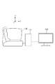
図1は光干渉断層撮影装置の構成の一例を示す図である。光干渉断層撮影装置は、データ取得部100、信号処理部101および表示部102を含む。なお、図1において、データ取得部100、信号処理部101および表示部102のそれぞれは独立しているが、データ取得部100に信号処理部101および表示部102の少なくとも一方が含まれることとしてもよい。
[Example 1]
FIG. 1 is a diagram showing an example of the configuration of an optical interference tomography apparatus. The optical interference tomography apparatus includes a
ここで、データ取得部100は、測定光を被検眼上で走査及び撮像することにより断層データを取得するOCTである。信号処理部101は、データ取得部100で取得された断層データから被検眼のOCTA画像を生成する情報処理装置である。表示部102は、信号処理部101で生成された被検眼のOCTA画像を表示するディスプレイである。以下、これらの構成について詳述する。
Here, the
まずデータ取得部100の構成について説明する。
First, the configuration of the
図2はデータ取得部100の構成の一例を示したものである。図2に示す光学系は眼底の断層データを取得するためのOCT光学系と眼底表面の画像を取得するためのSLO光学系とを含んでいる。
FIG. 2 shows an example of the configuration of the
被検眼Erに対向して対物レンズ1が設置され、その光軸上に第1ダイクロックミラー2および第2ダイクロイックミラー3が配置されている。これらのダイクロイックミラーによってOCT光学系の光路L1、被検眼Erの観察を行う為のSLO光学系と固視灯用の光路L2、および前眼部観察用の光路L3とに波長帯域ごとに分岐される。
The
SLO光学系と固視灯用の光路L2はSLO走査手段4、レンズ5および6、ミラー7、第3ダイクロイックミラー8、フォトダイオード9、SLO光源10、固視灯11を有している。
The SLO optical system and the optical path L2 for the fixation lamp include an SLO scanning means 4,
ミラー7は、穴あきミラーや中空のミラーが蒸着されたプリズムであり、SLO光源10による照明光と、被検眼からの戻り光とを分離する。第3ダイクロイックミラー8はSLO光源10および固視灯11への光路へと波長帯域ごとに分離する。
The mirror 7 is a prism on which a perforated mirror or a hollow mirror is vapor-deposited, and separates the illumination light from the
SLO走査手段4は、SLO光源10と固視灯11から発せられた光を被検眼Er上で走査するものであり、X方向に走査するXスキャナ、Y方向に走査するYスキャナから構成されている。本実施形態では、Xスキャナは高速走査を行う必要があるためポリゴンミラーによって、Yスキャナはガルバノミラーによって構成されている。
The SLO scanning means 4 scans the light emitted from the
レンズ5はSLO光学系および固視灯の焦点合わせのため、不図示のモータによって駆動される。SLO光源10は例えば780nm付近の波長の光を発生する。なお、本明細書において波長の数値は例示であり他の値とすることとしてもよい。フォトダイオード9は、被検眼からの戻り光を検出する。固視灯11は可視光を発生して被検者の固視を促すものである。
The
SLO光源10から発せられた光は、第3ダイクロイックミラー8で反射され、ミラー7を通過し、レンズ6、5を通り、SLO走査手段4によって、被検眼Er上で走査される。被検眼Erからの戻り光は、投影光と同じ経路を戻ったのち、ミラー7によって反射され、フォトダイオード9へと導かれる。
The light emitted from the SLO
固視灯11は第3ダイクロイックミラー8、ミラー7を透過し、レンズ6、5を通り、SLO走査手段4によって、被検眼Er上で走査される。このとき、SLO走査手段の動きに合わせて固視灯11を点滅させることによって、被検眼Er上の任意の位置に任意の形状をつくり、被検者の固視を促す。
The
前眼部観察用の光路L3には、レンズ12、スプリットプリズム13、レンズ14、前眼部観察用のCCD15が配置されている。このCCD15は、不図示の前眼部観察用光源の波長、例えば970nm付近に感度を持つものである。
A
スプリットプリズム13は、被検眼Erの瞳孔と共役な位置に配置されており、被検眼Erとデータ取得部100のZ方向(前後方向)の距離を、前眼部のスプリット像として検出することができる。
The
被検眼Erの画像データを撮像する為のOCT光学系の光路L1には、XYスキャナ16、レンズ17、18が配置されている。XYスキャナ16はOCT光源20からの光を被検眼上Erで走査するためのものである。XYスキャナ16は1枚のミラーとして図示してあるが、XY2軸方向の走査を行うガルバノミラーである。
An
レンズ17は、ファイバー21から出射するOCT光源20からの光を、被検眼Erに焦点合わせするためのものであり、不図示のモータによって駆動される。この焦点合わせによって、被検眼Erからの戻り光は同時にファイバー21の先端に、スポット状に結像されて入射されることとなる。
The
更に光カプラー19、OCT光源20、光カプラー19に接続され一体化している光ファイバー21〜24、レンズ25、分散補償用ガラス26、参照ミラー27、分光器28が配置されている。
Further, an
光ファイバー22を介してOCT光源20から出射された光は、測定光と参照光に光カプラー19にて分割される。測定光は光ファイバー21、OCT光学系の光路L1から対物レンズ1までを通じて被検眼Erに向けて出射される。この被検眼Erに向けて出射された測手光は被検眼Erにて反射散乱し同じ行路を通じて光カプラー19に達する。
The light emitted from the OCT
一方参照光は光ファイバー23を通じてレンズ25、分散補償用ガラス26を通じて参照ミラー27に向けて出射される。参照ミラー27から反射した参照光は同じ光路を通じて光カプラー19に達する。
On the other hand, the reference light is emitted toward the reference mirror 27 through the
このようにして光カプラー19に達した測定光と参照光は合波され干渉光となる。ここで、測定光の光路長と参照光の光路長がほぼ同一となったときに干渉を生じる。参照ミラー27は、不図示のモータおよび駆動機構によって光軸方向に調整可能に保持され、被検眼Erによって変わる測定光の光路長に参照光の光路長を合わせることが可能である。干渉光は光ファイバー24を介して分光器28に導かれる。
In this way, the measurement light and the reference light that have reached the
分光器28はレンズ29、31、回折格子30、ラインセンサ32から構成される。光ファイバー24から出射された干渉光はレンズ29を介して平行光となった後、回折格子30で分光され、レンズ31によってラインセンサ32に結像される。
The
本実施例では干渉系としてマイケルソン干渉系を用いたが、マッハツェンダー干渉系を用いても良い。測定光と参照光との光量差に応じて、光量差が大きい場合にはマッハツェンダー干渉系を、光量差が比較的小さい場合にはマイケルソン干渉系を用いることが望ましい。 In this embodiment, the Michelson interference system is used as the interference system, but a Mach-Zehnder interference system may be used. It is desirable to use the Mach-Zehnder interference system when the light amount difference is large and the Michelson interference system when the light amount difference is relatively small, depending on the light amount difference between the measured light and the reference light.
次に信号処理部101及び表示部102の構成について説明する。
Next, the configuration of the
図3は信号処理部101の機能構成の一例を示す図である。信号処理部101は記憶部34およびCPU44を備える。信号処理部101は例えばパーソナルコンピュータなどの情報処理装置である。記憶部34およびCPU44は互いに通信可能に接続されているまた、記憶部34およびCPU44は表示部102と通信可能に接続されている。記憶部34は、ROM(Read Only Memory)44を含む。ここで、CPU44がROM44に記憶されたプログラムを実行することで、CPU44は画像生成部33およびOCTAが像生成部35として機能する。
FIG. 3 is a diagram showing an example of the functional configuration of the
なお、信号処理部101が備えるCPUおよびROMは1つであってもよいし複数であってもよい。すなわち、少なくとも1以上のプロセッサと少なくとも1つのメモリとが接続されており、少なくとも1以上のプロセッサが少なくとも1以上のメモリに記憶されたプログラムを実行した場合に信号処理部101は上記の各手段として機能する。なお、処理装置はCPUに限定されるものではなく、GPU、ASIC、MPUまたはFPGA等であってもよい。また、少なくとも1以上のプロセッサとは、少なくとも1以上のコアを有するCPUを含む概念である。
The
画像生成部33は、データ取得部100によって取得されたデータに基づいて各種の画像を生成する。より具体的には、画像生成部33は、データ取得部100のフォトダイオード9、ラインセンサ32および記憶部34と通信可能に接続されている。SLO走査手段4を用いて被検眼ErをX方向、Y方向に走査した際にフォトダイオート9から得られる複数のデータから画像生成部33はSLO画像を生成する。ここで、SLO画像とは眼底を前眼部側から見た際の眼底表面を示す2次元画像である。
The
また画像生成部33はラインセンサ32から得られる干渉データをフーリエ変換し、得られるデータを輝度或いは濃度情報に変換することによって被検眼の深さ方向(Z方向)の画像を取得する。このようなスキャン方式をAスキャン、得られる断層画像をAスキャン画像と呼ぶ。
Further, the
このAスキャンを被検眼Erの所定の横断方向にXYスキャナ16にて走査することによって複数のAスキャン画像を取得することができる。例えばX方向に走査すればXZ面における断層画像が得られ、Y方向に走査すればYZ面における断層画像が得られる。このように被検眼Erを所定の横断方向に走査する方式をBスキャン、得られる断層画像をBスキャン画像と呼ぶ。
A plurality of A-scan images can be acquired by scanning this A-scan with the
更にBスキャンのXZ面或いはYZ面に対し、それに直行する方向に走査する方式をCスキャンと呼び、得られるXYZの3次元断層データをCスキャンデータと呼ぶ。 Further, a method of scanning the XZ plane or the YZ plane of the B scan in a direction orthogonal to the XZ plane or the YZ plane is called a C scan, and the obtained three-dimensional tomographic data of the XYZ is called a C scan data.
記憶部34は画像生成部33、OCTA画像生成部35、表示部102と接続され、画像生成部33から得られたSLO画像及び2次元或いは3次元の断層データを記憶すると共に、OCTA画像生成部35から得られた2次元或いは3次元のOCTAデータを記憶する。
The
OCTA画像生成部35は記憶部34と接続され、記憶部34から断層データを取得しOCTA画像(モーションコントラスト画像)を生成する。なおOCTA画像生成部35は後述にて詳細に説明する。
The OCTA
表示部102は記憶部34に記憶されたSLO画像及び断層データ、OCTAデータを表示する。表示部102は例えば液晶ディスプレイなどを含む。
The
以上説明したデータ取得部100、信号処理部101、表示部102から構成される光干渉断層撮影装置において、観察から撮影までの流れを説明する。
The flow from observation to imaging will be described in the optical interference tomography apparatus including the
まず観察について図4を用いて説明する。図4は観察時に表示部102に表示される画面の一例である。図4においては表示部102には前眼部観察像36とSLO画像38とが表示されている。なお、被検眼の観察時に表示部102に表示される画面は図4の例に限定されるものではない。
First, the observation will be described with reference to FIG. FIG. 4 is an example of a screen displayed on the
対物レンズ1の正面に被検眼Erが位置すると、撮影者は前眼部観察像36を見ながら被検眼Erとデータ取得部100とのXYZ方向の位置合わせを図示なきジョイスティックを用いて行う。XY方向の位置合わせは、例えば、前眼部観察像36の瞳孔中心が前眼部観察像の表示される画面の中心に位置するように操作者はデータ取得部100を操作する。Z方向の位置合わせでは、例えん、Z方向の位置合わせが適切でない場合点線37に沿って前眼部観察像36がスプリットされるので、スプリットされないように撮影者はデータ取得部100を操作する。なお、位置合わせは操作者により手動で行われることとしてもよいし、自動で行われることとしてもよい。また、手動および自動で位置合わせを行うこととしてもよい。また、位置合わせの手法は上記の方法に限定されるものではなく、既知の種々の手法を用いることとしてもよい。
When the eye to be inspected Er is positioned in front of the
上記のようにして被検眼とデータ取得部100とのXYZ方向の位置合わせが完了するとSLO走査手段4のXY方向の走査により生成されるSLO画像38が表示部102表示される。なお、SLO画像38が表示部102に表示されるタイミグは上記の例に限定されるものではない。この前眼部観察像36とSLO画像38とは随時更新され、撮影者は被検眼Erを略ディレイなく観察できる。
When the alignment of the eye to be inspected and the
更にSLO画像38中のスキャンエリア39はOCTAデータの取得時に走査されるエリアを示したものであり、SLO画像38に重畳されている。撮影者はこのスキャンエリア39をマウスやタッチパネル等の図示なき走査位置変更手段を操作し、所望の走査位置を設定する。これらの操作にて観察が終了する。
Further, the
次に撮影について説明する。撮影者により図示なき撮影開始ボタンを操作されると、データ取得部100はスキャンエリア39を測定光により走査する。OCTAでは同一断面つまり同一位置のBスキャンを繰り返し撮影し、その撮影間における被写体の時間的な変化を検出するものであるため、本実施例では同一位置のBスキャンをm回繰り返すものとする。本実施例のスキャンエリア39を走査する場合、スキャン位置Y1からYnまでのY方向の各位置においてBスキャンが繰り返しm回ずつ走査される。ただし、被検眼は動くため、常に眼底の同一位置を走査することができない場合がある。また、被検眼の追尾するトラッキング機能を有している場合もトラッキング機能の不完全さにより常に眼底の同一位置を走査することができない場合がある。すなわち、装置としては眼底の同一位置を走査するように制御された測定光であっても眼底の完全に同一位置を走査できるとは限らない。従って、本明細書における眼底の同一位置とは眼底の完全に同一位置のみならず眼底の略同一位置を含む。
Next, shooting will be described. When the photographer operates a shooting start button (not shown), the
なお本実施例において各BスキャンにおけるAスキャンはX方向にpサンプルの位置のデータから構成され、1つのAスキャンはZ方向にq個のデータから構成されるものとする。本実施例ではスキャンエリア39を走査することにより、XYZ平面でn×mのBスキャン(Aスキャン数としてはn×m×p、総データ数としてはn×m×p×q)が得られる。
In this embodiment, the A scan in each B scan is composed of the data at the position of the p sample in the X direction, and one A scan is composed of q data in the Z direction. In this embodiment, by scanning the
データ取得部100によってスキャンエリア39のデータ取得が完了すると、画像生成部33は例えば取得された全てのデータからBスキャン画像を生成する。具体的には画像生成部33は各Bスキャンに対してバックグランド減算およびフーリエ変換を行う。フーリエ変換により実部及び虚部からなる複素OCT信号が得られるので、画像生成部33は複素OCT信号の絶対値を計算することによってBスキャン画像を生成する。具体的には、データ取得部100は、n×mのBスキャン画像を生成する。すなわち、データ取得部100は、眼底の同一位置を走査するように制御された測定光に基づいて得られた、それぞれ眼底の断面を示す複数の断層データを取得する第1取得手段の一例に相当する。
When the data acquisition of the
画像生成部33によってBスキャン画像が生成されると、生成されたBスキャン画像は記憶部34に記憶されると共に、OCTA画像生成部35でOCTA画像が生成される。OCTA画像生成部35の具体的な処理については後述する。OCTA画像がOCTA画像生成部35で生成されると、OCTA画像は記憶部34に記憶されると共にCPU44が表示部102にOCTA画像を出力することで表示部102にOCTA画像が表示される。表示部102に表示されたOCTA画像を撮影者が確認することによって例えば、次の撮影を行うか否かを判断する。以上が観察から撮影までの説明となる。
When the B-scan image is generated by the
次にOCTA画像生成部35について詳細に説明する。
Next, the OCTA
このOCTA画像生成部35の説明の前に、ここで一旦被検眼Er内に存在し且つOCT光源20からの測定光の網膜への入射を遮る遮蔽物によって起こる陰影について図5を用いて説明する。図5はスキャンエリア39の或るY方向位置の網膜部のBスキャン画像の一例である。図5の上方は硝子体となっており、OCT光源20の測定光は図における上方より入射されるため、測定光の入射方向は矢印40のようになっている。
Prior to the description of the OCTA
更に図5中でX150は測定光の入射方向に網膜血管がある断層画像のX方向位置を示し、X170は測定光の入射方向に網膜血管がない断層画像のX方向位置、X70は測定光の入射方向に不図示の硝子体混濁がある断層画像のX方向位置を示している。 Further, in FIG. 5, X150 indicates the X-direction position of the tomographic image having a retinal blood vessel in the incident direction of the measurement light, X170 is the X-direction position of the tomographic image having no retinal blood vessel in the incident direction of the measurement light, and X70 is the X-direction position of the measurement light. It shows the X-direction position of a tomographic image with vitreous opacity (not shown) in the incident direction.
まずX方向位置X150の断層画像について説明すると、網膜血管E1を観察することができる。この網膜血管E1は一般に細長の高反射体として観察され、神経節細胞層から内顆粒層と外網状層の境界部付近にかけて存在するものである。網膜血管E1が存在すると測定光は網膜血管E1に遮られるため、その結果後方へ測定光が届きづらくなり陰影E2が生じる。陰影E2は断層画像上で低輝度にて観察される。 First, the tomographic image of the position X150 in the X direction will be described, and the retinal blood vessel E1 can be observed. This retinal blood vessel E1 is generally observed as an elongated high-reflector, and exists from the ganglion cell layer to the vicinity of the boundary between the inner nuclear layer and the outer plexiform layer. When the retinal blood vessel E1 is present, the measurement light is blocked by the retinal blood vessel E1, and as a result, it becomes difficult for the measurement light to reach the rear and a shadow E2 is generated. The shadow E2 is observed at low brightness on the tomographic image.
次にX方向位置X170の断層画像について説明すると、内境界膜から脈絡膜までの断層E3を陰影無に観察することができる。これは測定光の入射方向において網膜への測定光の入射を遮る遮蔽物がX方向位置X170に存在していないからである。 Next, the tomographic image of the position X170 in the X direction will be described. The tomographic E3 from the internal limiting membrane to the choroid can be observed without shadow. This is because there is no shield at the position X170 in the X direction that blocks the incident of the measured light on the retina in the incident direction of the measured light.
更にX方向位置X70の断層画像について説明すると、内境界膜から脈絡膜までの断層E4に陰影が生じていることが分かる。これは測定光の入射方向において不図示の硝子体混濁が存在し、測定光が硝子体混濁に遮られるためである。その為測定光の入射方向に見て硝子体混濁の後方位置に存在する内境界膜から脈絡膜までの断層に測定光が届きづらくなり陰影が生じているのである。 Further explaining the tomographic image of the position X70 in the X direction, it can be seen that the tomographic E4 from the internal limiting membrane to the choroid has a shadow. This is because there is vitreous turbidity (not shown) in the incident direction of the measurement light, and the measurement light is blocked by the vitreous turbidity. Therefore, it becomes difficult for the measurement light to reach the fault from the internal limiting membrane to the choroid, which exists behind the vitreous opacity when viewed in the incident direction of the measurement light, and shadows are generated.
このように測定光の入射方向に見て遮蔽物に対しその後方に存在する断層に陰影が生じる。また遮蔽物が被検眼ErのZ方向の何処の位置に存在するかによって陰影の生じるZ方向位置が変わると言える。 In this way, when viewed in the incident direction of the measured light, a shadow is generated on the fault existing behind the shield. Further, it can be said that the Z-direction position where the shadow is generated changes depending on the position of the shield in the Z-direction of the eye to be inspected Er.
本実施例では陰影の生じる例としてX方向位置X150(網膜血管E1)及びX方向位置X70(不図示の硝子体混濁がある場合)について例示したが、この他にも水晶体の混濁や網膜出血や硬性白斑などの場合で陰影)が生じる。水晶体混濁の場合にはX方向位置X170の断層画像に示したように内境界膜から脈絡膜までの断層に陰影が生じ、網膜出血や硬性白斑などの場合には、この網膜出血や硬性白斑が神経線維層から脈絡膜までの断層の何処のZ方向位置に発生するかによって陰影が生じるZ方向位置が変わる。 In this embodiment, the X-direction position X150 (retinal blood vessel E1) and the X-direction position X70 (when there is vitreous opacity (not shown)) are exemplified as examples of shadow formation, but in addition to this, lens opacity and retinal hemorrhage may occur. Shading) occurs in the case of hard white spots. In the case of lens opacification, a shadow is formed on the tomography from the internal limiting membrane to the choroid as shown in the tomographic image at position X170 in the X direction. The Z-direction position where the shadow is generated changes depending on the Z-direction position of the fault from the fiber layer to the choroid.
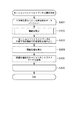
OCTA画像生成部35について図6を用いて説明する。図6はOCTA画像生成部35の処理(情報処理方法)の一例の流れを示したフローチャートである。
The OCTA
なおこのOCTA画像生成部35の説明は、データ取得部100によってスキャンエリア39のデータ取得(スキャン位置Y1からYnまでのY方向の各位置においてBスキャンがm回繰り返されて走査)が完了し、更に画像生成部33によって取得された全てのデータからBスキャン画像が生成された後の話となる。
In the explanation of the OCTA
まずOCTA画像生成部35はステップS201にてモーションコントラストデータ(モーションコントラスト値)を生成する。このステップS201のモーションコントラストデータの生成の詳細な説明は図7を用いて行う。図7はモーションコントラストデータ生成の一例を示すフローチャートである。
First, the OCTA
ステップS301では、OCTA画像生成部35はY方向位置Yiにおけるインデックスiを定義する。これによりY1からYnまでのY方向の各位置においてステップS302からステップS307までが繰り返されるようになっている。
In step S301, the OCTA
次にステップS302ではOCTA画像生成部35はY方向位置Yiに対応するm枚分のBスキャン画像を記憶部34から読み出す。
Next, in step S302, the OCTA
次にステップS303ではOCTA画像生成部35はステップS302で読みだされたm枚分のBスキャン画像の位置ずれを補正する。この位置ずれ補正が行われる理由は、モーションコントラストデータの生成には時間が異なる同じ位置のBスキャン画像を比較することが望ましいためである。この位置ずれ補正は例えばBスキャン画像同士の相関が最大になるように行われる。位置ずれ補正の方法は既知の他の方法を用いることとしてもよい。なお被写体が被検眼のように動くものではない場合やトラッキング(追尾)の性能が高い場合にはこの位置ずれ補正は不要である。
Next, in step S303, the OCTA
次にステップS304ではOCTA画像生成部35は位置ずれ補正されたm枚のBスキャン画像を画素毎に加算平均処理を行う。これによりm枚のBスキャン画像から加算平均処理された1枚のBスキャン画像(以下、加算平均画像と呼ぶ場合がある)が得られる。なお、
次にステップS305ではOCTA画像生成部35はこの加算平均処理された1枚のBスキャン画像を記憶部34に記憶する。なお、ステップS304,305は加算平均画像を用いる処理を実行する前に実行されていればよく、ステップS303の後に実行されなくともよい。
Next, in step S304, the OCTA
Next, in step S305, the OCTA
次にステップS306ではOCTA画像生成部35はステップS303で位置ずれ補正されたm枚分のBスキャン画像を用いてモーションコントラストデータを計算する。このモーションコントラストデータはステップS303で位置ずれ補正されたm枚分のBスキャン画像の画素毎の分散値を計算することによって得られる。すなわち、この分散値はモーションコントラスト値の一例である。なおモーションコントラストデータの計算方法は種々あり、本実施例以外にも画像生成部33で行われるフーリエ変換後、且つ絶対値の計算前の複素OCT信号を用いて、その位相差および/またはベクトル差を計算することによっても得ることができる。すなわち、モーションコントラスト値は上記の分散値に限定されるものではなく、画像間における変化のある部分と変化のない部分とを区別できる値であればよい。
Next, in step S306, the OCTA
次にステップS307ではOCTA画像生成部35はステップS306で得られたモーションコントラストデータを記憶部34に記憶する。
Next, in step S307, the OCTA
ステップS308において、OCTA画像生成部35はY方向位置Y1からYnまでのY方向の各位置においてS302からS307までが繰り返されたらモーションコントラストデータの生成処理を終了する。
In step S308, the OCTA
このようなステップS301からステップS308から構成されたステップS201により、OCTA画像生成部35はY方向位置Y1からYnまでのY方向の各位置のモーションコントラストデータを得ることができる
次にOCTA画像生成部35はステップS202にてセグメンテーションを実行する。ここでセグメンテーションとは画像から網膜の境界(層境界)を検出することを含む処理である。
By step S201 configured from step S301 to step S308, the OCTA
まずセグメンテーションではOCTA画像生成部35はステップS305で記憶された加算平均処理後のBスキャン画像を記憶部34から読み出す。加算平均処理後のBスキャン画像はY1からYnまでのY方向の各位置において記憶されており、その全てのY方向位置の加算平均処理後のBスキャン画像を読み出す。読み出しが終了すると次にOCTA画像生成部35は各Bスキャン画像に対して断層の境界位置を計算する。具体的には神経線維層、神経節細胞層、網膜色素上皮などの断層の境界位置を計算する。OCTA画像生成部35は断層の境界位置はBスキャン画像をZ方向にエッジ抽出処理を行い、抽出されたエッジプロファイルの解析を行う等することで境界位置を得る。各Bスキャン画像に対し各断層の境界位置が得られるとOCTA画像生成部35はその境界位置を示すデータを記憶部34に記憶させる。なお、境界位置が検出される度に記憶部34に境界位置を示すデータを記憶させることとしてもよい。また、上記の例では加算平均処理後のBスキャン画像から境界位置を検出することとしたが、加算平均処理をしていないBスキャン画像から境界位置を検出することとしてもよい。
First, in segmentation, the OCTA
次にOCTA画像生成部35はステップS203にてモーションコントラストデータの閾値処理を行う。このステップS203で行われるモーションコントラストデータの閾値処理の詳細な説明は図8を用いて行う。図8はモーションコントラストデータの閾値処理の一例を示すフローチャートである。図8のモーションコントラストデータの閾値処理はステップS401からステップS406までで構成されている。
Next, the OCTA
まずステップS401において、OCTA画像生成部35はY方向位置Yiにおけるインデックスiを定義する。これによりY1からYnまでのY方向の各位置においてステップS402からステップS405までが繰り返されるようになっている。
First, in step S401, the OCTA
次にステップS402ではOCTA画像生成部35は閾値を設定する。このステップS402で設定した閾値はステップS404で行われるモーションコントラストデータの閾値処理で用いられる。このステップS402については、図9を用いて更に詳細に説明する。図9は閾値設定のプロセスの一例を示したフローチャートである。
Next, in step S402, the OCTA
まずステップS501ではOCTA画像生成部35はステップS305で記憶されたY方向位置Yiに対応する加算平均処理後のBスキャン画像を記憶部34から読み出す。
First, in step S501, the OCTA
次にステップS502では、OCTA画像生成部35はステップS501で読みだされた加算平均処理後のBスキャン画像から陰影を検出する。そして、OCTA画像生成部35は検出した陰影の位置を示すデータを記憶部34に記憶させる。前述したように、陰影は測定光の入射方向に見て遮蔽物の後方位置に存在する断層に生じるものであり、陰影の生じるZ方向位置は遮蔽物が被検眼Erの何処のZ方向位置に存在するかによって変わるものである。そのためステップS502ではステップS501で読みだされた加算平均処理後のBスキャン画像を用いて、陰影がX方向の何処の位置に生じているか、測定光の入射方向に見て陰影がZ方向の何処の位置から後方で生じているかを検出する。
Next, in step S502, the OCTA
本実施例では陰影の検出方法を2例紹介するが別の方法であっても陰影が検出できればよい。 In this embodiment, two shadow detection methods will be introduced, but it is sufficient if the shadow can be detected even if another method is used.
1例目はBスキャン画像の輝度値から陰影を検出する方法である。この方法では、まずOCTA画像生成部35は陰影がX方向のどの位置に生じているかを検出する。OCTA画像生成部35は、Bスキャン画像をAスキャン単位に分割し、分割したAスキャン毎に全画素値の総和を計算する。陰影は陰影の生じていない部位に比べ低輝度で観察されるので、先程の総和の結果が所定値以下の数値を示すX方向位置を検出することによりX方向の陰影位置を検出することができる。上述の処理では陰影がZ方向の何処の位置から後方で生じているかまでは検出することができないため、次にOCTA画像生成部35は陰影がZ方向のどの位置から後方で生じているかを検出する。OCTA画像生成部35は、陰影が検出されたX方向位置のAスキャンを構成する各画素値と、その付近に在る陰影が検出されていないX方向位置のAスキャンを構成する各画素値とを同一のZ方向位置で比較する。陰影が検出されたX方向位置のAスキャンを構成する画素値がその付近に在る陰影が検出されていないX方向位置のAスキャンを構成する画素値よりも低い値を有するZ方向位置を検出することによって、陰影がZ方向のどの位置から後方で生じているかを検出することができる。なお、その付近に在る陰影が検出されていないX方向位置とは、例えば、陰影が検出されたX方向位置に最も近いX方向位置である。
The first example is a method of detecting a shadow from the brightness value of a B-scan image. In this method, the OCTA
2例目はBスキャン画像とステップS202で得られたセグメンテーションの結果とを用いて陰影を検出する方法である。この方法では、OCTA画像生成部35はまずセグメンテーションの結果を用いてBスキャン画像を各層に分割する。次に、OCTA画像生成部35は、測定光の入射方向から順に、言い換えると神経線維層、神経節細胞層、内網状層といった具合に硝子体側から順に各層のデータを抽出及びAスキャン単位に分割し、分割したAスキャン毎に全画素値の総和を計算する。陰影(シャドー)は陰影の生じていない部位に比べ低輝度で観察されるので、OCTA画像生成部35は、先程の総和の結果が所定値以下の数値を示すX方向位置を検出する。OCTA画像生成部35は、これを各層で繰り返すことにより、陰影がX方向の何処の位置に生じているか、Z方向の何処の層から後方で生じているかを検出する。神経線維層から脈絡膜までの全層において低輝度が検出される場合にはOCTA画像生成部35は、硝子体混濁あるいは水晶体混濁による陰影を検出することができる。また測定光の入射方向から見て神経節細胞層から内顆粒層と外網状層の境界に在るいずれかの層からその後方にかけて低輝度が検出される場合にはOCTA画像生成部35は網膜の血管による陰影を検出することができる。つまり測定光の入射方向から見て低輝度が検出された層からその後方にある全ての層にかけて低輝度が検出される場合には陰影であるものとして検出できる。
The second example is a method of detecting shadows using a B-scan image and the result of segmentation obtained in step S202. In this method, the OCTA
なお、陰影の抽出は加算平均処理をしていないBスキャン画像から行うこととしてもよい。また、他の方法として、OCTA画像生成部35はY方向位置Y1からYnまでそれぞれの位置から少なくとも1枚のBスキャン画像を読み出すと共にステップS202で得られたセグメンテーションデータを用いてEnface画像を生成する。そして、OCTA画像生成部35はそのEnface画像から陰影を検出することとしてもよい。ここでEnface画像は、セグメンテーションで抽出された任意の層のデータから各Aスキャンの代表値を決定しXY方向に2次元に生成した画像である。Enface画像の画素から所定値以下の数値を示す箇所が陰影となるので、各層を順に検出していくことにより陰影がXY方向の何処の位置に生じているか、測定光の入射方向から見てZ方向の何処の位置から後方で生じているかを検出することが可能となる。すなわち、OCTA画像生成部35は、複数の断層データの少なくとも1つにおける陰影領域を特定する特定手段の一例に相当する。
The shadow may be extracted from the B-scan image that has not been subjected to the averaging process. As another method, the OCTA
次にステップS503及びステップS504では、OCTA画像生成部35はX方向位置XkにおけるインデックスkとZ方向位置Zrにおけるインデックスrを定義する。これによりX方向位置X1からXp、Z方向位置Z1からZqまでのBスキャン画像の全ての画素位置においてステップS505及びステップS506、ステップS507を行うことができる。
Next, in steps S503 and S504, the OCTA
次にステップS505では、OCTA画像生成部35はステップS503及びステップS504で指定された位置(Xk、Zr)のBスキャン画像の画素がステップS502で検出された陰影に該当するか否かを判定する。
Next, in step S505, the OCTA
ステップS505でBスキャン画像の画素が陰影に該当しない場合にはステップS506にてOCTA画像生成部35は閾値Aを閾値処理に適用し、一方Bスキャン画像の画素が陰影に該当する場合にはステップS507にてOCTA画像生成部35は、閾値Aとは異なる閾値Bを閾値処理に適用する。すなわち、OCTA画像生成部35は、特定手段によって陰影領域が特定された場合、陰影領域に対応する信号強度値と比較される閾値を、陰影領域以外の領域に対応する信号強度値と比較される閾値とは異なる値に決定する決定手段の一例に相当する。なお、特定手段によって陰影領域が特定されなかった場合、断層データの同一深さ位置または同一層における複数位置の信号強度と比較される閾値を同一の値(閾値A)となる。
In step S505, when the pixel of the B scan image does not correspond to the shadow, the OCTA
この閾値A及びBは後述のステップS404で用いられ、この閾値の値が小さいほどモーションコントラストデータの検出感度が上がりノイズ成分も増す。逆に閾値の値が大きいほどモーションコントラストデータの検出感度が下がりノイズ成分が下がる。 The threshold values A and B are used in step S404 described later, and the smaller the threshold value, the higher the detection sensitivity of the motion contrast data and the higher the noise component. On the contrary, the larger the threshold value, the lower the detection sensitivity of the motion contrast data and the lower the noise component.
閾値Aの設定値は例えば画像生成部33によって生成されたBスキャン画像の中の被写体以外が表示されている部分、つまりランダムノイズのみが表示されている部分の輝度の平均値+2σとする。ここでσは標準偏差を示す。一方閾値Bの設定値は閾値Aの設定値に対して係数αを乗算した値とする。すなわち、OCTA画像生成部35は、陰影領域以外の領域に対応する信号強度値と比較される閾値に基づいて陰影領域に対応する信号強度値と比較される閾値を決定する。この係数αは遮蔽物によって生じた陰影による断層画像の輝度低下を補正する係数であり、例えば0より大きく1未満の値の固定値が設定されている。つまり、画素が陰影に該当するか否かによって異なる閾値が適用される。画素が陰影に該当しない場合の閾値Aに対して陰影に該当する閾値Bに低い値が設定される。すなわち、陰影領域に対応する信号強度値と比較される閾値は、陰影領域以外の領域に対応する信号強度値と比較される閾値よりも小さい値である。なお、従来の方法ではステップS505及びステップS507がなく設定される閾値は画素が陰影であるか否かを考慮せず固定値(閾値A)となっていた。
The set value of the threshold value A is, for example, the average value + 2σ of the brightness of the portion of the B-scan image generated by the
また、閾値Bは閾値Aと係数αから決定される値としたが、閾値Bは陰影による断層画像の輝度低下を補正する値であればよいので閾値Aを元に決定する必要はない。すなわち、閾値Bは閾値Aより小さい値であればよく、閾値Bの決定方法は上記の例に限定されるものではない。 Further, the threshold value B is a value determined from the threshold value A and the coefficient α, but since the threshold value B may be a value that corrects the decrease in the brightness of the tomographic image due to the shadow, it is not necessary to determine the threshold value A based on the threshold value A. That is, the threshold value B may be a value smaller than the threshold value A, and the method for determining the threshold value B is not limited to the above example.
なお前述では係数αを固定値とした場合を説明したが、強い陰影の部位においては係数αを小さく、弱い陰影の部位においては係数αを大きくするといったように、係数αを陰影の強さの関数としてもよい。すなわち、陰影が強い(信号強度値が小さい)ほど係数αを小さくすることとしてもよい。このようにOCTA画像生成部35は、陰影領域に対応する信号強度値と比較される閾値を、陰影領域に対応する信号強度値に応じて決定する。具体的には、OCTA画像生成部35は、陰影領域に対応する信号強度値が小さいほど陰影領域に対応する信号強度値と比較される閾値を小さくする。なお、上記の例では係数αを乗算することとしたが閾値Aから所定の係数を減算または所定の係数で除算することで、陰影領域に対応する信号強度値が小さいほど陰影領域に対応する信号強度値と比較される閾値を小さくすることとしてもよい。
In the above, the case where the coefficient α is set to a fixed value has been described, but the coefficient α is set to the strength of the shadow, such that the coefficient α is small in the strong shadow region and the coefficient α is large in the weak shadow region. It may be a function. That is, the coefficient α may be made smaller as the shadow is stronger (the signal strength value is smaller). As described above, the OCTA
このようにすることでスキャンエリア39の走査により得られた被検眼データの各陰影に対し其々適切な係数αの値を設定することができる。
By doing so, it is possible to set an appropriate coefficient α value for each shadow of the eye test data obtained by scanning the
例えば、網膜内の血管が遮蔽物となって生じる陰影では、血管がZ方向に太い場合には強い陰影が生じ、その陰影部の断層画像の輝度低下は大きい。血管がZ方向に細い場合には弱い陰影が生じ陰影部の断層画像の輝度低下は小さい。従って、上記のように係数αを陰影の部の信号強度値の関数とすることでより適切な閾値を決定することが可能となる。 For example, in a shadow generated by a blood vessel in the retina as a shield, a strong shadow is generated when the blood vessel is thick in the Z direction, and the brightness of the tomographic image of the shadow portion is greatly reduced. When the blood vessel is thin in the Z direction, a weak shadow is generated and the decrease in brightness of the tomographic image of the shadow portion is small. Therefore, it is possible to determine a more appropriate threshold value by using the coefficient α as a function of the signal intensity value in the shaded area as described above.
なお上述では陰影の強さを断層画像の輝度低下として表現したが、陰影の強さを示すものであれば断層画像の輝度低下以外のものであってもよく、結果として係数αが陰影の強さの関数となっていればよい。 In the above, the strength of the shadow is expressed as the decrease in the brightness of the tomographic image, but it may be something other than the decrease in the brightness of the tomographic image as long as it indicates the strength of the shadow, and as a result, the coefficient α is the strength of the shadow. It suffices if it is a function of.
ステップS508及びステップS509において、OCTA画像生成部35はX方向位置X1からXp、Z方向位置Z1からZqまでのBスキャン画像の全ての画素位置においてステップS505からステップS507が繰り返されたら処理を終了する。
In step S508 and step S509, the OCTA
このようなステップS501からステップS509から構成されたステップS402により、OCTA画像生成部35はY方向位置YiにおけるBスキャン画像の各画素に対し陰影を考慮した閾値を設定することができる。すなわち、OCTA画像生成部35は各画素に対して一律の閾値を設定するのではなく適応的な閾値を設定することができる。
By step S402 configured from step S501 to step S509, the OCTA
次にOCTA画像生成部35はステップS403にてステップS307で記憶部34に記憶されたY方向位置Yiに対応するモーションコントラストデータとステップS305で記憶されたY方向位置Yiに対応する加算平均処理後のBスキャンを記憶部34から読み出しする。
Next, in step S403, the OCTA
次にOCTA画像生成部35はステップS404にてモーションコントラストデータの閾値処理を行う。具体的にはOCTA画像生成部35は加算平均処理後のBスキャン画像の画素値(信号強度値)とステップS402で設定した閾値とを画素毎に比較し、加算平均処理後のBスキャン画像の画素値が閾値以下であれば、その画素に対応するモーションコントラストデータを0にする。
Next, the OCTA
一方で加算平均処理後のBスキャン画像の画素値が閾値以上であれば、その画素に対応するモーションコントラストデータの値を維持する。なお、モーションコントラストデータは0近傍の値であればよく完全に0としなくともよい。また、閾値との比較は加算平均処理が行われていないBスキャン画像の画素値であってもよい。すなわち、OCTA画像生成部35は、複数の断層データの少なくとも1つの断層データから得られた信号強度値と閾値とを比較する比較手段の一例に相当する。また、OCTA画像生成部35は、比較手段による比較結果および複数の断層データからモーションコントラスト値を取得する第2取得手段の一例に相当する。
On the other hand, if the pixel value of the B-scan image after the addition averaging process is equal to or greater than the threshold value, the value of the motion contrast data corresponding to that pixel is maintained. The motion contrast data may be a value close to 0 and may not be completely set to 0. Further, the comparison with the threshold value may be the pixel value of the B-scan image that has not been subjected to the averaging process. That is, the OCTA
次にOCTA画像生成部35はステップS404にて閾値処理されたモーションコントラストデータを記憶部34に記憶させる。
Next, the OCTA
ステップS406において、OCTA画像生成部35はY方向位置Y1からYnまでのY方向の各位置においてS402からS405までが繰り返されたら閾値処理を終了する。
In step S406, the OCTA
このようなステップS401からステップS406から構成されたステップS203によりOCTA画像生成部35は陰影を考慮した閾値を用いて閾値処理を行うことができる。
By step S203 configured from step S401 to step S406, the OCTA
次にステップS204ではOCTA画像生成部35はOCTA画像を生成する。具体的にはまずOCTA画像生成部35はステップS202で得られたセグメンテーションによる各層の境界位置を記憶部34から読み出す。次にOCTA画像生成部35はステップS203にて閾値処理されたモーションコントラストデータから任意の層のデータをセグメンテーションの各層の境界位置を用いて抽出する。そしてOCTA画像生成部35は任意の層のモーションコントラストデータに対して各Aスキャンの代表値を決定する。この代表値は平均値、最大値、中央値などいずれの値でもよい。OCTA画像生成部35は、この代表値をXY方向に2次元に生成することにより2次元OCTA画像を生成する。すなわち、OCTA画像生成部35は、第2取得手段により取得されたモーションコントラスト値に基づいて、モーションコントラスト画像を生成する生成手段の一例に相当する。OCTA画像生成部35は二次元OCTA画像を記憶部34に記憶させると共に、OCTA画像生成部35は二次元OCTA画像(以下、単にOCTA画像という場合がある)を表示部102に出力することで表示部102に表示させる。
Next, in step S204, the OCTA
図10はステップS204で生成された二次元OCTA画像と閾値を固定とする従来の方法により生成された二次元OCTA画像の例を示したものである。図10中で図10(a)及び図10(b)が本実施例により生成されたOCTA画像を示し、図10(c)及び図10(d)が従来の方法により生成されたOCTA画像を示している。従来方法の場合、ステップS402により設定される閾値は陰影があるか否かの考慮がされておらず固定値(閾値A)となっている。 FIG. 10 shows an example of the two-dimensional OCTA image generated in step S204 and the two-dimensional OCTA image generated by the conventional method of fixing the threshold value. In FIG. 10, FIGS. 10 (a) and 10 (b) show OCTA images generated by this embodiment, and FIGS. 10 (c) and 10 (d) show OCTA images generated by a conventional method. Shows. In the case of the conventional method, the threshold value set by step S402 is a fixed value (threshold value A) without considering whether or not there is a shadow.
更に図10(a)及び図10(c)は神経節細胞層のOCTA画像であり網膜血管の存在を確認することができる。図10(b)及び図10(d)は脈絡毛細管板(Choriocapillaris)のOCTA画像である。 Further, FIGS. 10 (a) and 10 (c) are OCTA images of the ganglion cell layer, and the presence of retinal blood vessels can be confirmed. 10 (b) and 10 (d) are OCTA images of the capillary lamina.
まず神経節細胞層のOCTA画像である図10(a)及び図10(c)に着目すると、両図は全く同じ画像となっている。これは神経節細胞層において陰影が存在していないので、結果として本実施例により生成された図10(a)はステップS505で閾値Aしか選択されないため、従来の方法により生成された図10(c)と同じ画像となっている。 First, focusing on FIGS. 10 (a) and 10 (c), which are OCTA images of the ganglion cell layer, both figures are exactly the same image. This is because there is no shadow in the ganglion cell layer, and as a result, only the threshold value A is selected in FIG. 10 (a) generated by this example in step S505, so that FIG. 10 (a) generated by the conventional method ( It is the same image as c).
一方、脈絡毛細管板(Choriocapillaris)のOCTA画像である図10(b)及び図10(d)に着目すると、従来の方法により生成された図10(d)は点Uにおいてアーチファクトが生じていることが分かる。このアーチファクトは図10(c)の血管に一致している。これは網膜血管が遮蔽物となって生じる陰影が脈絡毛細管板(Choriocapillaris)に存在しているからである。陰影部はBスキャン画像の画素値が低輝度になっているので閾値処理によってモーションコントラスト信号が0となってしまい、図10(d)の点Uにおいてアーチファクトが生じてしまうのである。一方で本実施例により生成された図10(b)は図10(d)の点Uと同一の場所である点Sにおいてアーチファクトが低減されていることが分かる。これは本実施例の場合にステップS402により設定される閾値は陰影が考慮され閾値Aより低い値に設定されているので、陰影部のようにBスキャン画像の画素値が低輝度になっていても閾値処理によってモーションコントラスト信号が0となることは無く値が維持されるからである。すなわち、陰影領域から適切なOCTA画像を得ることが可能となる。 On the other hand, focusing on FIGS. 10 (b) and 10 (d), which are OCTA images of the capillary lamina, FIG. 10 (d) generated by the conventional method shows that an artifact occurs at the point U. I understand. This artifact coincides with the blood vessel of FIG. 10 (c). This is because the shadow generated by the retinal blood vessels as a shield is present in the capillary lamina. Since the pixel value of the B-scan image is low in the shaded area, the motion contrast signal becomes 0 by the threshold processing, and an artifact occurs at the point U in FIG. 10 (d). On the other hand, it can be seen that in FIG. 10 (b) generated by this embodiment, the artifacts are reduced at the point S, which is the same place as the point U in FIG. 10 (d). This is because the threshold value set by step S402 in the case of this embodiment is set to a value lower than the threshold value A in consideration of the shadow, so that the pixel value of the B scan image is low brightness like the shadow portion. This is because the motion contrast signal does not become 0 by the threshold processing and the value is maintained. That is, it is possible to obtain an appropriate OCTA image from the shaded area.
また本実施例は陰影に該当する場所では閾値を閾値Aに比べ低い値の閾値Bにすることにより、アーチファクトを低減させる反面、部分的にはノイズ成分も増すという欠点もあるが、陰影に該当しない場所ではノイズ成分を抑える従来の設定値の閾値Aにすることができるので、全体としてはノイズが目立たないOCTA画像を提供できる。 Further, in this embodiment, by setting the threshold value to the threshold value B, which is lower than the threshold value A, in the place corresponding to the shadow, the artifact is reduced, but there is a drawback that the noise component is partially increased, but it corresponds to the shadow. Since the threshold value A of the conventional set value for suppressing the noise component can be set in a place where the noise component is not present, it is possible to provide an OCTA image in which the noise is inconspicuous as a whole.
なお上記実施形態ではSD−OCTを例に説明したが、タイムドメインOCTやSS−OCTであってもよい。 Although SD-OCT has been described as an example in the above embodiment, it may be time domain OCT or SS-OCT.
また、上記の実施例では、OCTA画像生成部35は、陰影に相当する画素に対して閾値Bを用いることとしたが、陰影に相当する画素を含むAスキャン画像の画素全てに対して閾値Bを適用することとしてもよい。すなわち、OCTA画像生成部35は、陰影領域を含むAスキャンデータの信号強度と比較される閾値を、陰影領域であるか否かに関わらず陰影領域に対応する信号強度値と比較される閾値に決定することとしてもよい。このようにしても陰影領域から適切なOCTA画像を得ることが可能となる。
Further, in the above embodiment, the OCTA
[実施例2]
実施例2の光干渉断層撮影装置の構成は実施例1における図1から図3に示す構成と同一の構成である。OCTA画像生成部35の処理の流れについては、実施例1で用いられた図6から図8のフローチャートが実施例2でも用いられる。一方で実施例1の図9のフローチャートが実施例2では図11のフローチャートに置き換えられており、実施例1のステップS501およびステップS502が実施例2ではステップ601及びステップS602に置き換えられている。図11中のフローチャートにおいて実施例1と同一のステップについては同一番号が付与されている。なお被検眼の観察及び撮影の方法については実施例1と同様である為、説明を省略する。
[Example 2]
The configuration of the optical interference tomography apparatus of the second embodiment is the same as the configuration shown in FIGS. 1 to 3 in the first embodiment. Regarding the processing flow of the OCTA
まずステップS201及びステップS202においてOCTA画像生成部35によりY方向位置Y1からYnまでのY方向の各位置におけるモーションコントラストデータの生成とセグメンテーションが実施例1と同様に行われる。
First, in steps S201 and S202, the OCTA
次にステップS203にてOCTA画像生成部35によりモーションコントラストデータの閾値処理が行われる。このステップS203はステップS401からステップS406によって構成され、まずステップS401ではOCTA画像生成部35によりY方向位置Yiにおけるインデックスiが定義される。次にステップS402ではOCTA画像生成部35は閾値を設定する。このステップS402における閾値設定のプロセスは図11のフローチャートに示されており。ステップS601からステップS602、そしてステップS503からステップS509によって構成されている。
Next, in step S203, the OCTA
ステップS601でOCTA画像生成部35はステップS307で記憶部34に記憶されたY方向位置Yiに対応するモーションコントラストデータを記憶部34から読み出す。
In step S601, the OCTA
次にステップS602では、OCTA画像生成部35はステップS601で読み出されたモーションコントラストデータを用いて、陰影がX方向の何処の位置に生じているか、測定光の入射方向から見て陰影がZ方向の何処の位置から後方で生じているかを検出する。実施例1では陰影の検出はBスキャン画像から行われていたが、実施例2ではモーションコントラスト信号から陰影が検出される。
Next, in step S602, the OCTA
実施例1で示したようにステップS201で得られるモーションコントラストデータは血管部の位置を示しており、かつ血管部の後方位置に陰影が生じる。そのため、OCTA画像生成部35はステップS602においてモーションコントラストデータが所定値以上の数値を有する画素を測定光の入射方向に其々探索及び特定し、特定した位置より後方に位置する画素を陰影の生じる位置とする。OCTA画像生成部35はこれをAスキャン毎に行うことで陰影がX方向の何処の位置に生じているか、測定光の入射方向に見て陰影がZ方向の何処の位置から後方で生じているかを検出することができる。すなわち、OCTA画像生成部35は、複数の断層データから得られるモーションコントラスト値に基づいて陰影領域を特定する。
As shown in Example 1, the motion contrast data obtained in step S201 indicates the position of the blood vessel portion, and a shadow is generated at the posterior position of the blood vessel portion. Therefore, in step S602, the OCTA
次にステップS503からステップS509において、OCTA画像生成部35はY方向位置YiにおけるBスキャン画像の各画素に対し陰影を考慮した閾値を設定する。これは実施例1と同様であるため説明を省略する。
Next, in steps S503 to S509, the OCTA
このようなステップS402により閾値が設定されると次にOCTA画像生成部35は実施例1と同様にステップS403からステップS406を行う。これによりステップS203のモーションコントラストデータの閾値処理が行われる。
When the threshold value is set by such step S402, the OCTA
そして最後に実施例1と同様にステップS204においてOCTA画像が生成される。 Finally, the OCTA image is generated in step S204 as in the first embodiment.
実施例2は陰影の検出方法がモーションコントラストデータを用いて行われるという点で実施例1と異なるが、ステップS402より設定される閾値は実施例1と同様に陰影が考慮された低い値が設定される。従って実機例2のステップS204で得られるOCTA画像も実施例1と同様の効果を得たものとなる。 Example 2 is different from Example 1 in that the shadow detection method is performed using motion contrast data, but the threshold value set from step S402 is set to a low value in consideration of shadows as in Example 1. Will be done. Therefore, the OCTA image obtained in step S204 of the actual machine example 2 also has the same effect as that of the first embodiment.
なお、実施例1と実施例2とを組み合わせることとしてもよい。例えば、OCTA画像生成部35は、ステップS502で検出された陰影とよびS602で検出された陰影とで共通する画素を、閾値を変更すべき画素としてもよい。このようにすることで、陰影の検出精度を向上できる可能性がある。
In addition, you may combine Example 1 and Example 2. For example, the OCTA
[実施例3]
実施例3の光干渉断層撮影装置の構成は図1から図3に示す構成と同一の構成である。OCTA画像生成部35の処理の流れも実施例1と同一であり、実施例3においても図6から図9のフローチャートが用いられる。実施例1ではステップS201からステップS204により生成されたOCTA画像が表示部102に表示されるまでを示したが、実施例3では実施例1で表示されたOCTA画像を見た撮影者が例えばGUI等を用いてXY平面上の各位置における閾値を個別に変更する場合について記載する。
[Example 3]
The configuration of the optical interference tomography apparatus of the third embodiment is the same as the configuration shown in FIGS. 1 to 3. The processing flow of the OCTA
ステップS201からステップS204により生成されたOCTA画像が表示部102に表示されると、撮影者はOCTA画像を見て陰影によるアーチファクトが出ているかどうかを判断する。もし撮影者が陰影によるアーチファクトが出ていると判断すると、撮影者はマウスなどの不図示の操作手段を用いてアーチファクトが出ているXY平面上の領域を選択する。OCTA画像生成部35は、この操作者による選択を受け付ける。図12は陰影によるアーチファクトが生じた脈絡毛細管板(Choriocapillaris)のOCTA画像の一例である。また、図12にて実線で示される領域41は、撮影者によって選定された陰影によるアーチファクトの生じている領域である。
When the OCTA image generated by step S201 to step S204 is displayed on the
撮影者によってアーチファクトの生じている領域41が選択されると、次に操作者は不図示の操作手段を用いて、領域41の閾値B(或いは係数α)の設定値をいくつにするかを指定する。OCTA画像生成部35は、操作者による閾値Bの変更を受け付ける。すなわち、OCTA画像生成部35は、操作者による陰影領域に対応する信号強度値と比較される閾値の変更を受け付ける受付手段の一例に相当する。この閾値B(或いは係数α)の撮影者による設定方法は例えばテキストボックスまたはスライドバー等を用いる方法とすることが可能である。なお、OCTA画像生成部35は、領域41の選択を受け付けたことを契機にテキストボックスまたはスライドバーを表示部102に表示させることとしてもよい。また、テキストボックスまたはスライドバーなどのGUIを用いる方法以外に、例えばマウスホイールの回転に伴い閾値が変更されることとしてもよい。
When the
OCTA画像生成部35が閾値Bの変更を受け付けると、OCTA画像生成部35は指定された領域41の位置に対応するモーションコントラストデータを記憶部34から読み出す。そしてOCTA画像生成部35は、撮影者によって設定された閾値Bでモーションコントラストデータの閾値処理を実行し、閾値処理後のOCTA画像を表示部102に再表示する。すなわち、OCTA画像生成部35は閾値Bの変更による結果をリアルタイムにOCTA画像に反映する。すなわち、受付手段が陰影領域に対応する信号強度値と比較される閾値の変更を受け付ける度に、第2取得手段はモーションコントラスト値を取得し、生成手段はモーションコントラスト画像を生成する。これらの処理は、例えば、アーチファクトが生じている領域がなくなったと撮影者が判断するまで繰り返される。
When the OCTA
また陰影によるアーチファクトの生じている領域が領域41とは別の領域に存在している場合には、撮影者はマウスなどの不図示の操作手段を用いてアーチファクトが出ているXY平面上の領域42を新たに選択し、領域41にて設定された閾値Bとは別の値の閾値Bを領域42に設定することができる。例えば、OCTA画像生成部35は、領域42の選択を受け付けたことを契機に領域41用のテキストボックスなどとは別に領域42用のテキストボックスなどを表示部102に表示させる。領域42においても同様に撮影者によって設定された閾値Bを用いてOCTA画像生成部35は領域42の位置に対応するモーションコントラストデータの閾値処理を行い、閾値処理後のOCTA画像を表示部102に表示させる。なお、閾値Bを変更する領域は領域41,42の2箇所に限定されるものではなく、3箇所以上閾値を変更することとしてもよいし、1箇所でもよい。
Further, when the region where the artifact due to the shadow is generated exists in a region different from the
このようにOCTA画像に生じた陰影によるアーチファクトを撮影者が確認し、XY平面上の各位置で撮影者自らが適切な閾値を設定することができるので、撮影者はストレスのなく陰影によるアーチファクトが低減されたOCTA画像を得ることが可能となる。 In this way, the photographer can confirm the shadow-induced artifacts generated in the OCTA image, and the photographer can set an appropriate threshold value at each position on the XY plane. It is possible to obtain a reduced OCTA image.
なお脈絡毛細管板(Choriocapillaris)のOCTA画像を本実施例では示したが、陰影によるアーチファクトの生じている領域に対して層毎に撮影者が閾値を設定できるようにしてもよい。 Although the OCTA image of the capillary lamina is shown in this embodiment, the photographer may be able to set a threshold value for each layer for the region where the artifact due to the shadow is generated.
なお、実施例3は実施例1,2とは独立に実施されることとしてもよい。すなわち、閾値を陰影に応じて適応的に自動設定するのではなく、操作者に閾値の変更を任せることとしてもよい。また、実施例3を実施例1および/または実施例2と組み合わせることとしてもよい。この場合、自動的に閾値を設定したもののアーチファクトが残っていると操作者が判断する場合には、操作者の好みに応じて閾値を変更できるため、より操作者が望む画質のOCTA画像を得ることが可能となる。 In addition, Example 3 may be carried out independently of Examples 1 and 2. That is, instead of automatically setting the threshold value adaptively according to the shadow, the operator may be left to change the threshold value. Further, Example 3 may be combined with Example 1 and / or Example 2. In this case, if the operator determines that an artifact remains even though the threshold is automatically set, the threshold can be changed according to the operator's preference, so that an OCTA image with a higher image quality desired by the operator can be obtained. Is possible.
[実施例4]
実施例4の光干渉断層撮影装置の構成は図1から図3に示す構成と同一の構成である。OCTA画像生成部35の処理の流れも実施例1と同一であり、実施例4においても図6から図9のフローチャートが用いられる。実施例1ではステップS506で用いられた閾値Aが固定値の場合について説明したが、本実施例4では閾値Aが固定値ではない場合について説明する。
[Example 4]
The configuration of the optical interference tomography apparatus of Example 4 is the same as the configuration shown in FIGS. 1 to 3. The processing flow of the OCTA
実施例1で固定値とされていた閾値AはBスキャン画像の中のランダムノイズのみが表示されている部分の平均値+2σ(σ=標準偏差)としていたのだが、これはBスキャン画像中のランダムノイズ成分がBスキャン画像中の何処の位置でも変わらないことを前提としている。しかしながら、ラインセンサ32から得られる干渉データのノイズ特性は低周波成分と高周波成分とで異なる可能性があるため、フーリエ変換後に得られるBスキャン画像中のランダムノイズ成分の値もZ方向の位置で値が変化する可能性がある。
The threshold value A, which was set as a fixed value in Example 1, was set to the average value + 2σ (σ = standard deviation) of the portion where only random noise is displayed in the B scan image, but this is in the B scan image. It is assumed that the random noise component does not change at any position in the B-scan image. However, since the noise characteristics of the interference data obtained from the
そこで実施例4では画像生成部33により例えば被写体が何も撮影されていないBスキャン画像を取得する。そして、OCTA画像生成部35は被写体が写っていないBスキャン画像中の各Z方向位置に対してX方向に平均値及び標準偏差σを計算し、平均値+2σ(σ=標準偏差)を閾値Aとして設定する。このようにすることで閾値AはZ方向の位置で変化するノイズ特性を考慮したものとなる。従って、例えば、同一深さ位置または同一層の画素値と比較される閾値Aは陰影を考慮しない場合同一の値となる。
Therefore, in the fourth embodiment, the
一方、実施例4のステップS507で設定される閾値Bは上述で設定された閾値Aに対して陰影の影響を補正する係数αを乗算したものとする。ここで乗算される係数αは実施例1で示したように固定値でもよいし、係数αを陰影の強さに応じて変化する値としてもよい。従って、OCTA画像生成部35は、陰影領域に対応する信号強度値と比較される閾値を、陰影領域以外に対応する領域であり且つ陰影領域と同一深さ位置または同一層の信号強度値と比較される閾値とは異なる値に決定することとなる。
On the other hand, the threshold value B set in step S507 of the fourth embodiment is assumed to be obtained by multiplying the threshold value A set above by the coefficient α for correcting the influence of the shadow. The coefficient α to be multiplied here may be a fixed value as shown in the first embodiment, or the coefficient α may be a value that changes according to the strength of the shadow. Therefore, the OCTA
このようにすることで陰影と陰影以外の場所とで適切な閾値を設定することができるので、OCTA画像内の陰影のある箇所はアーチファクトが低減された画像を提供でき、陰影以外の箇所は血管の抽出精度のよいOCTA画像を提供することができる。 By doing so, it is possible to set an appropriate threshold value between the shadow and the place other than the shadow, so that the part with the shadow in the OCTA image can provide an image with reduced artifacts, and the part other than the shadow is a blood vessel. It is possible to provide an OCTA image with good extraction accuracy.
なお本実施例では閾値Bは閾値Aと係数αから決定される値としたが、閾値Bは陰影による断層画像の輝度低下を補正する値であればよいので閾値Aを元に決定する必要はない。 In this embodiment, the threshold value B is a value determined from the threshold value A and the coefficient α, but the threshold value B may be a value that corrects the decrease in brightness of the tomographic image due to shading, so it is necessary to determine the threshold value A based on the threshold value A. No.
なお本実施例では閾値AをZ方向の位置で変化するノイズ特性を元に設定したが、例えばZ方向の位置で変化する干渉信号の強度を元に設定してもよい。すなわち、干渉信号の強度が低いほど閾値Aを低くするようにしてもよい。 In this embodiment, the threshold value A is set based on the noise characteristic that changes at the position in the Z direction, but for example, the threshold value A may be set based on the intensity of the interference signal that changes at the position in the Z direction. That is, the lower the intensity of the interference signal, the lower the threshold value A may be.
また、本実施例4を実施例1−3の少なくとも1つの実施例と組み合わせて実施することとしてもよい。 Moreover, you may carry out this Example 4 in combination with at least one Example of Example 1-3.
[実施例5]
上記の実施例1−4では、陰影に該当するか否かによって閾値を閾値Aと閾値Bとで切り替えることによって陰影によって生じるアーチファクトを低減させる例について説明したが、本発明は上記の実施例に限定されるものではない。
[Example 5]
In the above-mentioned Examples 1-4, an example of reducing the artifact caused by the shadow by switching the threshold value between the threshold value A and the threshold value B depending on whether or not the shadow is applicable has been described. Not limited.
本実施例においては、閾値を切り替えるのではく、断層画像の輝度を変更する例について説明する。具体的には、OCTA画像生成部35は、ある画素が陰影に該当するかによって閾値を切り替えるのではなく、陰影に該当するかによって断層画像の輝度を変更する。
In this embodiment, an example of changing the brightness of the tomographic image instead of switching the threshold value will be described. Specifically, the OCTA
OCTA画像生成部35は、例えば、陰影に該当する画素の輝度値(信号強度値)を上昇させ、陰影に該当しない画素の輝度値(陰影領域以外の領域に対応する信号強度値)は維持する。なお、輝度値を上昇させる方法しては、例えばオフセット値を画素に加える。輝度値を上昇させる量(オフセット量)は、一律の値であってもよいし、元の輝度値に応じた量としてもよい。例えば、OCTA画像生成部35は、元の輝度値が小さいほど輝度値を上昇させる量を大きくする。
The OCTA
なお、本実施例においては閾値Bを用いず閾値Aを用いる。すなわち、上昇させられた信号強度と比較される閾値は、陰影領域以外の領域であり且つ陰影領域と同一深さ位置または同一層の信号強度と比較される閾値と同じ値である。 In this embodiment, the threshold value A is used instead of the threshold value B. That is, the threshold value compared with the increased signal strength is the same value as the threshold value compared with the signal strength in the region other than the shaded region and at the same depth position as the shaded region or in the same layer.
また、輝度値を上昇させる対象としては、加算平均処理後のBスキャン画像の画素でもよいし、加算平均処理が行われていないBスキャン画像の画素でもよい。すなわち、OCTA画像生成部35は、複数の断層データの少なくとも1つの断層データか得られた陰影領域に対応する信号強度値を上昇させる制御手段の一例に相当する。そして、本実施例においては、OCTA画像生成部35は、上昇させられた信号強度値と閾値とを比較することで閾値処理を実行する。
Further, the target for increasing the luminance value may be the pixels of the B-scan image after the addition averaging process or the pixels of the B-scan image not subjected to the addition averaging process. That is, the OCTA
本実施例によっても、陰影領域から適切なOCTA画像を得ることが可能となる。 Also in this embodiment, it is possible to obtain an appropriate OCTA image from the shaded area.
なお、本実施例5を実施例1−4の少なくとも1つの実施例と組み合わせて実施することとしてもよい。例えば、閾値Aは固定の値でなくともよい。また、閾値を切り替えるとともに本実施例のように輝度値を変更することとしてもよい。 In addition, this Example 5 may be carried out in combination with at least one Example of Example 1-4. For example, the threshold value A does not have to be a fixed value. Further, the threshold value may be switched and the luminance value may be changed as in the present embodiment.
[その他の実施例]
以上、実施例を詳述したが、本発明は例えば、システム、装置、方法、プログラム若しくは記録媒体(記憶媒体)等としての実施態様をとることが可能である。具体的には、複数の機器(例えば、ホストコンピュータ、インタフェース機器、撮像装置、Webアプリケーション等)から構成されるシステムに適用しても良いし、また、一つの機器からなる装置に適用しても良い。
[Other Examples]
Although the examples have been described in detail above, the present invention can be implemented as, for example, a system, an apparatus, a method, a program, a recording medium (storage medium), or the like. Specifically, it may be applied to a system composed of a plurality of devices (for example, a host computer, an interface device, an image pickup device, a Web application, etc.), or may be applied to a device consisting of one device. good.
また、本発明の目的は、以下のようにすることによって達成されることはいうまでもない。即ち、前述した実施形態の機能を実現するソフトウェアのプログラムコード(コンピュータプログラム)を記録した記録媒体(または記憶媒体)を、システムあるいは装置に供給する。係る記憶媒体は言うまでもなく、コンピュータ読み取り可能な記憶媒体である。そして、そのシステムあるいは装置のコンピュータ(またはCPUやMPU)が記録媒体に格納されたプログラムコードを読み出し実行する。この場合、記録媒体から読み出されたプログラムコード自体が前述した実施形態の機能を実現することになり、そのプログラムコードを記録した記録媒体は本発明を構成することになる。 Needless to say, the object of the present invention is achieved by doing the following. That is, a recording medium (or storage medium) in which a program code (computer program) of software that realizes the functions of the above-described embodiment is recorded is supplied to the system or device. Needless to say, the storage medium is a computer-readable storage medium. Then, the computer (or CPU or MPU) of the system or device reads and executes the program code stored in the recording medium. In this case, the program code itself read from the recording medium realizes the function of the above-described embodiment, and the recording medium on which the program code is recorded constitutes the present invention.
以上、本発明の好ましい実施形態について詳述したが、本発明は係る特定の実施形態に限定されるものではなく、特許請求の範囲に記載された本発明の要旨の範囲内において、種々の変形・変更が可能である。 Although the preferred embodiments of the present invention have been described in detail above, the present invention is not limited to the specific embodiment, and various modifications are made within the scope of the gist of the present invention described in the claims.・ Can be changed.
100 データ取得部
101 信号処理部
102 表示部
33 画像生成部
34 記憶部
35 OCTA画像生成部
43 CPU
44 ROM
100
44 ROM
Claims (21)
前記陰影領域に対応する信号強度値と比較される閾値を、前記陰影領域以外の第2の領域に対応する信号強度値と比較される閾値よりも小さい値に決定する決定手段と、
前記複数の断層データのうち少なくとも1つの断層データにおける前記陰影領域に対応する信号強度値と比較される閾値と、前記第2の領域に対応する信号強度値と比較される閾値と、を用いた閾値処理であって、前記複数の断層データと前記閾値処理による結果とを用いて得たモーションコントラスト値に基づいて、モーションコントラスト画像を生成する生成手段と、
を備えることを特徴とする情報処理装置。 A shaded area in at least one slice data among a plurality of tomographic data indicating the fundus of a section obtained based on controlled measuring light to scan the same position of the fundus, the measurement light to the fundus A specific means for identifying a first region, which is a shaded region formed by a shield that blocks the incident light of the light beam.
A determination means for determining a threshold value to be compared with the signal strength value corresponding to the shadow region to a value smaller than the threshold value to be compared with the signal strength value corresponding to the second region other than the shadow region.
A threshold value to be compared with the signal intensity value corresponding to the shadow region in at least one tomographic data among the plurality of tomographic data and a threshold value to be compared with the signal intensity value corresponding to the second region were used. a threshold processing, on the basis of the motion contrast value obtained by using the result by the threshold processing and the plurality of tomographic data, and generating means for generating a motion contrast image,
An information processing device characterized by being equipped with.
前記第1の領域に対応する信号強度値と比較される閾値を、前記第2の領域に対応する信号強度値と比較される閾値よりも小さい値に決定する決定手段と、
前記複数の断層データのうち少なくとも1つの断層データにおける前記第1の領域に対応する信号強度値と比較される閾値と、前記第2の領域に対応する信号強度値と比較される閾値と、を用いた閾値処理であって、前記複数の断層データと前記閾値処理による結果とを用いて得たモーションコントラスト値に基づいて、モーションコントラスト画像を生成する生成手段と、
を備えることを特徴とする情報処理装置。 A shaded area in at least one slice data among a plurality of tomographic data indicating the fundus of a section obtained based on controlled measuring light to scan the same position of the fundus, the measurement light to the fundus a first region containing the shadow area formed by the shield that blocks the incident, with low signal strength value than the signal strength value corresponding to a different second realm from said first region Specific means for specifying the first region and
A determination means for determining the threshold value to be compared with the signal strength value corresponding to the first region to a value smaller than the threshold value to be compared with the signal strength value corresponding to the second region.
Wherein a plurality of threshold values to be compared with the signal strength values corresponding to the first region in at least one slice data among the tomographic data, and a threshold value to be compared with the signal strength value corresponding to the second region In the threshold value processing used, a generation means for generating a motion contrast image based on a motion contrast value obtained by using the plurality of tomographic data and the result of the threshold value processing, and
An information processing device characterized by being equipped with.
前記受付手段が前記第1の領域に対応する信号強度値と比較される閾値の変更を受け付ける度に、前記モーションコントラスト値が取得され、前記モーションコントラスト画像が生成されることを特徴とする請求項1乃至9のいずれか1項に記載の情報処理装置。 Further provided with a receiving means for accepting a change in the threshold value to be compared with the signal strength value corresponding to the first region by the operator.
The claim is characterized in that each time the receiving means accepts a change in a threshold value to be compared with a signal strength value corresponding to the first region, the motion contrast value is acquired and the motion contrast image is generated. The information processing apparatus according to any one of 1 to 9.
前記複数の断層データのうち少なくとも1つの断層データにおける前記陰影領域に対応する信号強度値を上昇させることにより得た信号強度値と比較される閾値と、前記陰影領域以外の第2の領域に対応する信号強度値と比較される閾値と、を用いた閾値処理であって、前記複数の断層データと前記閾値処理による結果とを用いて得たモーションコントラスト値に基づいて、モーションコントラスト画像を生成する生成手段と、
を備えることを特徴とする情報処理装置。 A shaded area in at least one slice data among a plurality of tomographic data indicating the fundus of a section obtained based on controlled measuring light to scan the same position of the fundus, the measurement light to the fundus A specific means for identifying a first region, which is a shaded region formed by a shield that blocks the incident light of the light beam.
A threshold to be compared with the signal intensity values obtained by raising the signal strength value corresponding to the shaded area in at least one slice data among the plurality of tomographic data, corresponding to a second region other than the shadow area It is a threshold value processing using a threshold value to be compared with the signal strength value to be performed, and a motion contrast image is generated based on the motion contrast value obtained by using the plurality of tomographic data and the result of the threshold value processing. Generation means and
An information processing device characterized by being equipped with.
前記複数の断層データのうち少なくとも1つの断層データにおける前記第1の領域に対応する信号強度値を上昇させることにより得た信号強度値と比較される閾値と、前記第2の領域に対応する信号強度値と比較される閾値と、を用いた閾値処理であって、前記複数の断層データと前記閾値処理による結果とを用いて得たモーションコントラスト値に基づいて、モーションコントラスト画像を生成する生成手段と、
を備えることを特徴とする情報処理装置。 A shaded area in at least one slice data among a plurality of tomographic data indicating the fundus of a section obtained based on controlled measuring light to scan the same position of the fundus, the measurement light to the fundus a first region containing the shadow area formed by the shield that blocks the incident, with low signal strength value than the signal strength value corresponding to a different second realm from said first region Specific means for specifying the first region and
A threshold value to be compared with the signal intensity value obtained by increasing the signal intensity value corresponding to the first region in at least one tomographic data among the plurality of tomographic data, and a signal corresponding to the second region. A generation means for generating a motion contrast image based on a motion contrast value obtained by using a threshold value to be compared with an intensity value and a threshold value obtained by using the plurality of tomographic data and the result of the threshold value processing. When,
An information processing device characterized by being equipped with.
前記眼底に対して前記測定光を走査する走査手段と、を備え、
前記制御された測定光が照射された前記眼底からの戻り光と参照光とを合波して得た干渉光を検出するように構成されることを特徴とする光干渉断層撮影装置。 The information processing apparatus according to any one of claims 1 to 14.
A scanning means for scanning the measurement light with respect to the fundus is provided.
An optical interference tomography apparatus characterized in that it is configured to detect interference light obtained by combining the return light from the fundus and the reference light irradiated with the controlled measurement light.
前記陰影領域に対応する信号強度値と比較される閾値を、前記陰影領域以外の第2の領域に対応する信号強度値と比較される閾値よりも小さい値に決定する決定工程と、
前記複数の断層データのうち少なくとも1つの断層データにおける前記陰影領域に対応する信号強度値と比較される閾値と、前記第2の領域に対応する信号強度値と比較される閾値と、を用いた閾値処理であって、前記複数の断層データと前記閾値処理による結果とを用いて得たモーションコントラスト値に基づいて、モーションコントラスト画像を生成する生成工程と、
を含むことを特徴とする情報処理方法。 A shaded area in at least one slice data among a plurality of tomographic data indicating the fundus of a section obtained based on controlled measuring light to scan the same position of the fundus, the measurement light to the fundus A specific step of identifying a first region, which is a shaded region formed by a shield that blocks the incident light of the light beam.
A determination step of determining a threshold value to be compared with the signal strength value corresponding to the shadow region to a value smaller than the threshold value to be compared with the signal strength value corresponding to the second region other than the shadow region.
A threshold value to be compared with the signal intensity value corresponding to the shadow region in at least one tomographic data among the plurality of tomographic data and a threshold value to be compared with the signal intensity value corresponding to the second region were used. In the threshold value processing, a generation step of generating a motion contrast image based on a motion contrast value obtained by using the plurality of tomographic data and the result of the threshold value processing, and
An information processing method characterized by including.
前記第1の領域に対応する信号強度値と比較される閾値を、前記第2の領域に対応する信号強度値と比較される閾値よりも小さい値に決定する決定工程と、
前記複数の断層データのうち少なくとも1つの断層データにおける前記第1の領域に対応する信号強度値と比較される閾値と、前記第2の領域に対応する信号強度値と比較される閾値と、を用いた閾値処理であって、前記複数の断層データと前記閾値処理による結果とを用いて得たモーションコントラスト値に基づいて、モーションコントラスト画像を生成する生成工程と、
を含むことを特徴とする情報処理方法。 A shaded area in at least one slice data among a plurality of tomographic data indicating the fundus of a section obtained based on controlled measuring light to scan the same position of the fundus, the measurement light to the fundus a first region containing the shadow area formed by the shield that blocks the incident, with low signal strength value than the signal strength value corresponding to a different second realm from said first region The specific step of specifying the first region and
A determination step of determining the threshold value to be compared with the signal strength value corresponding to the first region to a value smaller than the threshold value to be compared with the signal strength value corresponding to the second region.
Wherein a plurality of threshold values to be compared with the signal strength values corresponding to the first region in at least one slice data among the tomographic data, and a threshold value to be compared with the signal strength value corresponding to the second region In the threshold value processing used, a generation step of generating a motion contrast image based on a motion contrast value obtained by using the plurality of tomographic data and the result of the threshold value processing, and
An information processing method characterized by including.
前記複数の断層データのうち少なくとも1つの断層データにおける前記陰影領域に対応する信号強度値を上昇させることにより得た信号強度値と比較される閾値と、前記陰影領域以外の第2の領域に対応する信号強度値と比較される閾値と、を用いた閾値処理であって、前記複数の断層データと前記閾値処理による結果とを用いて得たモーションコントラスト値に基づいて、モーションコントラスト画像を生成する生成工程と、
を含むことを特徴とする情報処理方法。 A shaded area in at least one slice data among a plurality of tomographic data indicating the fundus of a section obtained based on controlled measuring light to scan the same position of the fundus, the measurement light to the fundus A specific step of identifying a first region, which is a shaded region formed by a shield that blocks the incident light of the light beam.
A threshold to be compared with the signal intensity values obtained by raising the signal strength value corresponding to the shaded area in at least one slice data among the plurality of tomographic data, corresponding to a second region other than the shadow area It is a threshold value processing using a threshold value to be compared with the signal strength value to be performed, and a motion contrast image is generated based on the motion contrast value obtained by using the plurality of tomographic data and the result of the threshold value processing. Generation process and
An information processing method characterized by including.
前記複数の断層データのうち少なくとも1つの断層データにおける前記第1の領域に対応する信号強度値を上昇させることにより得た信号強度値と比較される閾値と、前記第2の領域に対応する信号強度値と比較される閾値と、を用いた閾値処理であって、前記複数の断層データと前記閾値処理による結果とを用いて得たモーションコントラスト値に基づいて、モーションコントラスト画像を生成する生成工程と、
を含むことを特徴とする情報処理方法。 A shaded area in at least one slice data among a plurality of tomographic data indicating the fundus of a section obtained based on controlled measuring light to scan the same position of the fundus, the measurement light to the fundus a first region containing the shadow area formed by the shield that blocks the incident, with low signal strength value than the signal strength value corresponding to a different second realm from said first region The specific step of specifying the first region and
A threshold value to be compared with the signal intensity value obtained by increasing the signal intensity value corresponding to the first region in at least one tomographic data among the plurality of tomographic data, and a signal corresponding to the second region. A generation step of generating a motion contrast image based on a motion contrast value obtained by using a threshold value to be compared with an intensity value and a threshold value obtained by using the plurality of tomographic data and the result of the threshold value processing. When,
An information processing method characterized by including.
Priority Applications (2)
| Application Number | Priority Date | Filing Date | Title |
|---|---|---|---|
| JP2016213422A JP6971559B2 (en) | 2016-10-31 | 2016-10-31 | Information processing equipment, information processing methods and programs |
| US15/797,311 US10672127B2 (en) | 2016-10-31 | 2017-10-30 | Information processing apparatus, information processing method, and program |
Applications Claiming Priority (1)
| Application Number | Priority Date | Filing Date | Title |
|---|---|---|---|
| JP2016213422A JP6971559B2 (en) | 2016-10-31 | 2016-10-31 | Information processing equipment, information processing methods and programs |
Publications (3)
| Publication Number | Publication Date |
|---|---|
| JP2018068748A JP2018068748A (en) | 2018-05-10 |
| JP2018068748A5 JP2018068748A5 (en) | 2019-10-17 |
| JP6971559B2 true JP6971559B2 (en) | 2021-11-24 |
Family
ID=62019900
Family Applications (1)
| Application Number | Title | Priority Date | Filing Date |
|---|---|---|---|
| JP2016213422A Active JP6971559B2 (en) | 2016-10-31 | 2016-10-31 | Information processing equipment, information processing methods and programs |
Country Status (2)
| Country | Link |
|---|---|
| US (1) | US10672127B2 (en) |
| JP (1) | JP6971559B2 (en) |
Families Citing this family (7)
| Publication number | Priority date | Publication date | Assignee | Title |
|---|---|---|---|---|
| US10588572B2 (en) * | 2017-05-08 | 2020-03-17 | Oregon Health & Science University | Bulk motion subtraction in optical coherence tomography angiography |
| WO2020049828A1 (en) * | 2018-09-06 | 2020-03-12 | キヤノン株式会社 | Image processing apparatus, image processing method, and program |
| JP2020039430A (en) * | 2018-09-06 | 2020-03-19 | キヤノン株式会社 | Image processing device, image processing method and program |
| JP7305401B2 (en) * | 2018-09-06 | 2023-07-10 | キヤノン株式会社 | Image processing device, method of operating image processing device, and program |
| WO2020075345A1 (en) * | 2018-10-10 | 2020-04-16 | キヤノン株式会社 | Medical image processing device, medical image processing method, and program |
| DE102020102012B4 (en) | 2020-01-28 | 2022-12-01 | Carl Zeiss Meditec Ag | Arrangement with an OCT device for determining a 3D reconstruction of an object region volume and computer program and computer-implemented method therefor |
| CN112587302B (en) * | 2021-03-04 | 2021-06-18 | 季华实验室 | Femtosecond laser real-time dynamic positioning focusing system and method |
Family Cites Families (20)
| Publication number | Priority date | Publication date | Assignee | Title |
|---|---|---|---|---|
| US6293674B1 (en) * | 2000-07-11 | 2001-09-25 | Carl Zeiss, Inc. | Method and apparatus for diagnosing and monitoring eye disease |
| PL1994361T3 (en) * | 2006-01-19 | 2017-01-31 | Optovue, Inc. | A fourier-domain optical coherence tomography imager |
| US7995814B2 (en) * | 2006-06-26 | 2011-08-09 | California Institute Of Technology | Dynamic motion contrast and transverse flow estimation using optical coherence tomography |
| JP4909378B2 (en) * | 2009-06-02 | 2012-04-04 | キヤノン株式会社 | Image processing apparatus, control method therefor, and computer program |
| US20140221827A1 (en) * | 2011-06-07 | 2014-08-07 | California Institute Of Technology | Enhanced optical angiography using intensity contrast and phase contrast imaging methods |
| US8433393B2 (en) * | 2011-07-07 | 2013-04-30 | Carl Zeiss Meditec, Inc. | Inter-frame complex OCT data analysis techniques |
| JP6230262B2 (en) * | 2012-12-28 | 2017-11-15 | キヤノン株式会社 | Image processing apparatus and image processing method |
| JP6507615B2 (en) * | 2013-12-13 | 2019-05-08 | 株式会社ニデック | Optical coherence tomography apparatus and program |
| JP6243763B2 (en) * | 2014-03-14 | 2017-12-06 | テルモ株式会社 | Image processing apparatus, method of operating image processing apparatus, and program |
| US10398302B2 (en) * | 2014-05-02 | 2019-09-03 | Carl Zeiss Meditec, Inc. | Enhanced vessel characterization in optical coherence tomograogphy angiography |
| JP6520099B2 (en) * | 2014-06-30 | 2019-05-29 | 株式会社ニデック | Optical coherence tomography apparatus and data processing program |
| JP2016093240A (en) * | 2014-11-12 | 2016-05-26 | キヤノン株式会社 | Image processing apparatus and image processing method |
| US9700206B2 (en) * | 2015-02-05 | 2017-07-11 | Carl Zeiss Meditec, Inc. | Acquistion and analysis techniques for improved outcomes in optical coherence tomography angiography |
| WO2017019626A1 (en) * | 2015-07-25 | 2017-02-02 | Lightlab Imaging, Inc. | Guidewire detection systems, methods, and apparatuses |
| JP6627342B2 (en) * | 2015-09-04 | 2020-01-08 | 株式会社ニデック | OCT motion contrast data analysis device, OCT motion contrast data analysis program. |
| US10264963B2 (en) * | 2015-09-24 | 2019-04-23 | Carl Zeiss Meditec, Inc. | Methods for high sensitivity flow visualization |
| US10492682B2 (en) * | 2015-10-21 | 2019-12-03 | Nidek Co., Ltd. | Ophthalmic analysis device and ophthalmic analysis program |
| US10123689B2 (en) * | 2015-10-28 | 2018-11-13 | Oregon Health & Science University | Systems and methods for retinal layer segmentation in OCT imaging and OCT angiography |
| US10130250B2 (en) * | 2015-11-02 | 2018-11-20 | Nidek Co., Ltd. | OCT data processing apparatus and OCT data processing program |
| US10402965B1 (en) * | 2015-11-12 | 2019-09-03 | Carl Zeiss Meditec, Inc. | Systems and methods for reducing artifacts in OCT angiography images |
-
2016
- 2016-10-31 JP JP2016213422A patent/JP6971559B2/en active Active
-
2017
- 2017-10-30 US US15/797,311 patent/US10672127B2/en active Active
Also Published As
| Publication number | Publication date |
|---|---|
| US10672127B2 (en) | 2020-06-02 |
| JP2018068748A (en) | 2018-05-10 |
| US20180122077A1 (en) | 2018-05-03 |
Similar Documents
| Publication | Publication Date | Title |
|---|---|---|
| JP6971559B2 (en) | Information processing equipment, information processing methods and programs | |
| JP6057567B2 (en) | Imaging control apparatus, ophthalmic imaging apparatus, imaging control method, and program | |
| KR102031604B1 (en) | Image generation method, image generation apparatus and computer program | |
| JP5836634B2 (en) | Image processing apparatus and method | |
| US9408532B2 (en) | Image processing apparatus and image processing method | |
| WO2016120933A1 (en) | Tomographic imaging apparatus, tomographic imaging method, image processing apparatus, image processing method, and program | |
| CN110786821B (en) | OCT device and recording medium | |
| WO2011007632A1 (en) | Tomography apparatus and tomogram correction processing method | |
| JP6909109B2 (en) | Information processing equipment, information processing methods, and programs | |
| US9642519B2 (en) | Image processing apparatus and control method of image processing apparatus | |
| KR20120120349A (en) | Ophthalmologic imaging apparatus | |
| US9700199B2 (en) | Image processing apparatus and image processing method | |
| US9662005B2 (en) | Image processing apparatus, image processing method, and program | |
| JP2016220735A (en) | Optical coherence tomography device and control method thereof | |
| JP6503665B2 (en) | Optical coherence tomography apparatus and program | |
| JP2020022723A (en) | OCT apparatus and OCT image processing program | |
| JP2018191761A (en) | Information processing device, information processing method, and program | |
| JP6888643B2 (en) | OCT analysis processing device and OCT data processing program | |
| JP2019042203A (en) | Image processing apparatus, optical interference tomographic imaging apparatus, image processing method, and program | |
| EP3375349B1 (en) | Information processing apparatus, image generation method, and computer-readable medium | |
| JP7204345B2 (en) | Image processing device, image processing method and program | |
| WO2023008385A1 (en) | Anterior eye part analysis device, anterior eye part analysis method, and program | |
| JP6776317B2 (en) | Image processing equipment, image processing methods and programs | |
| JP2018000373A (en) | Ophthalmologic imaging apparatus, control method thereof, and program | |
| WO2019198629A1 (en) | Image processing device and control method for same |
Legal Events
| Date | Code | Title | Description |
|---|---|---|---|
| A521 | Request for written amendment filed |
Free format text: JAPANESE INTERMEDIATE CODE: A523 Effective date: 20190902 |
|
| A621 | Written request for application examination |
Free format text: JAPANESE INTERMEDIATE CODE: A621 Effective date: 20190902 |
|
| A131 | Notification of reasons for refusal |
Free format text: JAPANESE INTERMEDIATE CODE: A131 Effective date: 20200721 |
|
| A977 | Report on retrieval |
Free format text: JAPANESE INTERMEDIATE CODE: A971007 Effective date: 20200717 |
|
| A521 | Request for written amendment filed |
Free format text: JAPANESE INTERMEDIATE CODE: A523 Effective date: 20200917 |
|
| A131 | Notification of reasons for refusal |
Free format text: JAPANESE INTERMEDIATE CODE: A131 Effective date: 20210302 |
|
| A521 | Request for written amendment filed |
Free format text: JAPANESE INTERMEDIATE CODE: A523 Effective date: 20210423 |
|
| TRDD | Decision of grant or rejection written | ||
| A01 | Written decision to grant a patent or to grant a registration (utility model) |
Free format text: JAPANESE INTERMEDIATE CODE: A01 Effective date: 20211005 |
|
| A61 | First payment of annual fees (during grant procedure) |
Free format text: JAPANESE INTERMEDIATE CODE: A61 Effective date: 20211102 |
|
| R151 | Written notification of patent or utility model registration |
Ref document number: 6971559 Country of ref document: JP Free format text: JAPANESE INTERMEDIATE CODE: R151 |