JP6968085B2 - Display device - Google Patents
Display device Download PDFInfo
- Publication number
- JP6968085B2 JP6968085B2 JP2018548282A JP2018548282A JP6968085B2 JP 6968085 B2 JP6968085 B2 JP 6968085B2 JP 2018548282 A JP2018548282 A JP 2018548282A JP 2018548282 A JP2018548282 A JP 2018548282A JP 6968085 B2 JP6968085 B2 JP 6968085B2
- Authority
- JP
- Japan
- Prior art keywords
- patient
- indicator
- handling device
- patient handling
- bed
- Prior art date
- Legal status (The legal status is an assumption and is not a legal conclusion. Google has not performed a legal analysis and makes no representation as to the accuracy of the status listed.)
- Active
Links
Images


Classifications
-
- A—HUMAN NECESSITIES
- A61—MEDICAL OR VETERINARY SCIENCE; HYGIENE
- A61G—TRANSPORT, PERSONAL CONVEYANCES, OR ACCOMMODATION SPECIALLY ADAPTED FOR PATIENTS OR DISABLED PERSONS; OPERATING TABLES OR CHAIRS; CHAIRS FOR DENTISTRY; FUNERAL DEVICES
- A61G7/00—Beds specially adapted for nursing; Devices for lifting patients or disabled persons
- A61G7/05—Parts, details or accessories of beds
-
- A—HUMAN NECESSITIES
- A61—MEDICAL OR VETERINARY SCIENCE; HYGIENE
- A61G—TRANSPORT, PERSONAL CONVEYANCES, OR ACCOMMODATION SPECIALLY ADAPTED FOR PATIENTS OR DISABLED PERSONS; OPERATING TABLES OR CHAIRS; CHAIRS FOR DENTISTRY; FUNERAL DEVICES
- A61G7/00—Beds specially adapted for nursing; Devices for lifting patients or disabled persons
- A61G7/002—Beds specially adapted for nursing; Devices for lifting patients or disabled persons having adjustable mattress frame
- A61G7/012—Beds specially adapted for nursing; Devices for lifting patients or disabled persons having adjustable mattress frame raising or lowering of the whole mattress frame
-
- A—HUMAN NECESSITIES
- A61—MEDICAL OR VETERINARY SCIENCE; HYGIENE
- A61G—TRANSPORT, PERSONAL CONVEYANCES, OR ACCOMMODATION SPECIALLY ADAPTED FOR PATIENTS OR DISABLED PERSONS; OPERATING TABLES OR CHAIRS; CHAIRS FOR DENTISTRY; FUNERAL DEVICES
- A61G2203/00—General characteristics of devices
- A61G2203/10—General characteristics of devices characterised by specific control means, e.g. for adjustment or steering
- A61G2203/12—Remote controls
-
- A—HUMAN NECESSITIES
- A61—MEDICAL OR VETERINARY SCIENCE; HYGIENE
- A61G—TRANSPORT, PERSONAL CONVEYANCES, OR ACCOMMODATION SPECIALLY ADAPTED FOR PATIENTS OR DISABLED PERSONS; OPERATING TABLES OR CHAIRS; CHAIRS FOR DENTISTRY; FUNERAL DEVICES
- A61G2203/00—General characteristics of devices
- A61G2203/10—General characteristics of devices characterised by specific control means, e.g. for adjustment or steering
- A61G2203/20—Displays or monitors
-
- A—HUMAN NECESSITIES
- A61—MEDICAL OR VETERINARY SCIENCE; HYGIENE
- A61G—TRANSPORT, PERSONAL CONVEYANCES, OR ACCOMMODATION SPECIALLY ADAPTED FOR PATIENTS OR DISABLED PERSONS; OPERATING TABLES OR CHAIRS; CHAIRS FOR DENTISTRY; FUNERAL DEVICES
- A61G2203/00—General characteristics of devices
- A61G2203/30—General characteristics of devices characterised by sensor means
Description
本開示は、例えば、病院設備などの設備の構成をモニタするシステム又はデバイスに関する。 The present disclosure relates to a system or device that monitors the configuration of equipment, such as hospital equipment.
病院設備は、所定の患者あるいは使用についての個々の属性に合わせるように調整可能である。例えば、病院のベッドは、患者をベッドへ又はベッドから移動させるのを補助するべく調整可能であり、あるいは、患者の移動を補助するように構成されたハンドルが付いている。また、例えば、病院のベッドは、夜間など、患者に付き添いがいない間、ベッドに患者を維持するように構成されている。様々なタイプの病院家具など、その他の設備も、同様に調整可能である。 Hospital equipment can be adjusted to suit individual attributes for a given patient or use. For example, a hospital bed can be adjusted to assist in moving the patient to or out of bed, or has a handle configured to assist in moving the patient. Also, for example, a hospital bed is configured to keep the patient in the bed during the absence of the patient, such as at night. Other equipment, such as various types of hospital furniture, can be adjusted as well.
夜間、あるいは、病院職員が患者と共に病室にいない場合など、患者に付き添いがいない間の、患者と設備との相互作用をモニタするためには、不適切な設備の構成を認識するために、設備にモニタ装置取り付けることができる。例えば、病院のベッドに、そのベッドの一般的に不適切な構成を認識するデバイス装置を設けるようにしてもよい。 Equipment to recognize inappropriate equipment configurations to monitor patient-equipment interactions during the absence of a patient, such as at night or when hospital staff are not in the hospital room with the patient. The monitor device can be attached to. For example, a hospital bed may be provided with a device device that recognizes the generally improper configuration of the bed.
しかしながら、従来のシステムは、通常、患者の装置の使用に関する情報を、担当スタッフに提供するものではない。例えば、病院のベッドの場合、従来の表示器は、例えば、能力が高い患者とそうでない患者の両方に関する情報といった、様々なタイプの患者の変化する症状についての病院の設備の十分な情報を介護者に提供するものではない。 However, conventional systems usually do not provide information about the patient's use of the device to the staff in charge. For example, in the case of hospital beds, traditional indicators care for sufficient information on hospital equipment for the changing symptoms of different types of patients, for example information about both competent and non-capable patients. It is not provided to the person.
本開示は、上記の問題を克服するものである。 The present disclosure overcomes the above problems.
本開示の一実施例では、患者の介護装置、この患者の介護装置に配置したセンサ、及び患者の介護装置に装着可能な表示器デバイスを具える装置が開示されている。この表示器デバイスは、患者のタイプを表示器デバイスに入力する入力デバイスと、ユーザのステータスを出力する表示器を具える。この表示器は、患者のタイプと、センサで検知した患者の介護装置の構成に基づいてユーザのステータスを出力する。 In one embodiment of the present disclosure, a device including a patient care device, a sensor arranged in the patient care device, and a display device that can be attached to the patient care device is disclosed. The indicator device comprises an input device that inputs the patient type to the indicator device and an indicator that outputs the user's status. This indicator outputs the user's status based on the patient type and the configuration of the patient's care device detected by the sensor.
別の実施例では、本開示は、患者の操作装置の構成を検出する一またはそれ以上のセンサと、この一またはそれ以上のセンサに操作可能に取り付けた表示器デバイスを具える患者の操作装置を開示する。この表示器デバイスは、患者のタイプに関する情報を入力できるユーザインターフェースと、入力した患者のタイプに関する情報と、一またはそれ以上のセンサで検出した患者の操作装置の検出した構成とに基づいてステータス通知を出す表示器とを具える。 In another embodiment, the present disclosure comprises a patient operating device comprising one or more sensors that detect the configuration of the patient operating device and an indicator device operably attached to the one or more sensors. To disclose. This indicator device provides status notifications based on a user interface that allows you to enter information about the patient type, information about the patient type that you enter, and the configuration detected by the patient's controls detected by one or more sensors. It is equipped with a display that outputs.
一実施例では、上述した装置及び/又は患者の操作装置を、患者の操作装置の一またはそれ以上の部分に脱着自在に連結した持ち運び可能なハンドヘルドデバイスとして構成することができる。例えば、表示器デバイスは、患者の操作装置の複数個所に着脱自在に取り付けることができる調整可能なフックを具えていてもよい。この表示器デバイスは、患者の操作装置の一またはそれ以上の部分に、ワイヤレスで又はケーブルで接続されていてもよい。 In one embodiment, the device described above and / or the patient's operating device can be configured as a portable handheld device detachably coupled to one or more portions of the patient's operating device. For example, the display device may be equipped with adjustable hooks that can be detachably attached to a plurality of locations on the patient's operating device. The indicator device may be connected wirelessly or by cable to one or more parts of the patient's operating device.
一実施例では、患者のタイプに関する情報が、安定した患者のタイプか、あるいは不安定な患者のタイプである。この患者のタイプに関する情報は、患者の移動度及び/又はレベルに関するものであってもよい。更に、結果に関するステータス及び/又はステータスの通知は、患者に適切なステータス、あるいは、患者に不適切なステータスである。 In one embodiment, the information about the patient type is either a stable patient type or an unstable patient type. The information about this patient type may be about the patient's mobility and / or level. In addition, the status and / or status notification regarding the result is a status appropriate for the patient or inappropriate for the patient.
一実施例では、この表示器は、システムステータスの表示器であり、患者の操作システムのステータスを通知する。このシステムステータス表示器は、光学部材及び/又は音響デバイスとして構成することができる。このシステムステータス表示器は、表示器デバイスの遠位端に配置され、反射用のグラウンド放射光を向けるように方向付けられ、構成された一またはそれ以上の光学部材として構成することができる。 In one embodiment, this indicator is a system status indicator, notifying the status of the patient's operating system. The system status indicator can be configured as an optical member and / or an acoustic device. The system status indicator is located at the distal end of the indicator device, directed to direct ground radiation for reflection, and can be configured as one or more configured optics.
一実施例では、この装置及び/又は患者の操作装置が更に、複数のキャスタと、この複数のキャスタを選択的に制動する一またはそれ以上のブレーキを具えていてもよい。少なくとも一のセンサが、複数のキャスタが一またはそれ以上のブレーキによって係止されているかどうかを検出し、表示器はブレーキステータスの通知を出すブレーキ表示器であってもよい。 In one embodiment, the device and / or the patient's operating device may further comprise a plurality of casters and one or more brakes that selectively brake the plurality of casters. At least one sensor may detect whether the plurality of casters are locked by one or more brakes, and the indicator may be a brake indicator that gives a brake status notification.
一実施例では、この表示器が患者の操作装置の電源の状態を表示する電源状態表示器であってもよい。 In one embodiment, the indicator may be a power status indicator that displays the power status of the patient's operating device.
一実施例では、この装置及び/又は患者の操作装置が、ベッド、患者リフト、患者のストレッチャー、及び患者の起立補助器であってもよい。ベッドとして構成されている場合は、装置は、バッテリィ寿命の量あるいはその他の入手可能な電力を検出する電源センサと;ベッドが高い位置にあるか、低い位置にあるか、あるいは中間位置にあるかを検出する高さ位置センサと;一またはそれ以上のサイドレールが上がっているか、下がっているか、あるいは中間位置にあるかを検出するサイドレール検出センサと;ベッドの一またはそれ以上のホィール又はキャスタがロックされているまたは制動された位置にあるかどうかを検出するブレーキセンサと;ベッドの背もたれ部分が水平であるか、あるいは上がった位置にあるか、又は背もたれ位置の角度を検出する、背もたれ位置センサと;マットレス及び/又はマットレスのセクション又は部分の圧力を検出するマットレス圧力センサ(例えば、一またはそれ以上の膨張可能なセルまたはベッドの膨張可能なセクションの圧力);患者サポートを通る空気流量を検出する患者サポート空気流センサと;圧力セラピー及び/又はパーカッションセラピーを交互に行う時を検出する膨張式物理療法用マットレスセンサ;患者がベッドを離れる、あるいはほぼ離れた場合を検出するベッド出入りセンサと;ベッドの位置が積極的に変化していることを決定するベッド調整センサ(例えば、背もたれが上がっている、あるいはCPR位置に置かれているなど);及び/又は、これらの組み合わせ、を具えていてもよい。表示器デバイスは、様々なセンサに対応する一またはそれ以上の構成部材表示器を具えていてもよい(例えば、電源入手可能性;高い、低い、あるいは中間のベッド高さ;高い、低い、又は中間のサイドレール位置;ベッドホイール/キャスタの係止が外れているあるいは制動されている;高い、あるいは低い背もたれ;シート部分などのマットレスの一またはそれ以上の部分における膨張不足及び/又は圧力過多の圧力;患者の支持具を通る過剰な又は遅い空気流;膨張可能なマットレスによって送達される活性又は不活性治療;ベッドが調整される過程にあり様々な位置をとるかどうか;患者がベッドから出ている又はベッドを離れているかどうかを決める;その他)。患者のリフトとして構成されている場合、この装置は、バッテリィの寿命、又はその他の入手可能な電力を検出する電源センサと、患者の吊り具が患者のホイストに固定されているかどうかを検出する吊り具アタッチメントセンサと、患者の出入りを検出する負荷センサ、患者のリフトの一またはそれ以上のホイール又はキャスタが係止されている、あるいは制動位置にあるかどうかを検出するブレーキセンサと、吊り具の適切な高さ、又は吊り具の中の患者の適切な位置を検出する吊り具位置センサ、及び/又はこれらの組み合わせを具えていてもよい。表示器デバイスは、様々なセンサに相当する一またはそれ以上の構成部材表示器を具えていてもよい(例えば、入手可能な電源用のディスプレイ又は表示器;ベッドのホイール/キャスタ用の係止がはずれているあるいは制動しているブレーキ;吊り具アタッチメント又は固定具;患者の体重又は吊り具内の出入りの検出;及び/又は吊り具の適切な及び/又は不適切な高さ;吊り具内の患者の適切な及び/又は不適切な位置;など) In one embodiment, the device and / or the patient's operating device may be a bed, a patient lift, a patient's stretcher, and a patient's standing aid. When configured as a bed, the device is with a power sensor that detects the amount of battery life or other available power; whether the bed is in a high, low, or intermediate position. With a height position sensor to detect; with a side rail detection sensor to detect if one or more side rails are up, down, or in the middle position; with one or more wheels or casters on the bed. With a brake sensor that detects if is in the locked or braked position; the backrest position that detects whether the back of the bed is horizontal or raised, or the angle of the backrest position. Sensors and mattress pressure sensors that detect pressure in the mattress and / or section or portion of the mattress (eg, pressure in the inflatable section of one or more inflatable cells or beds); air flow through the patient support. Patient support airflow sensor to detect; inflatable physiotherapy mattress sensor to detect when pressure therapy and / or percussion therapy alternate; bed entry / exit sensor to detect when the patient leaves or is almost away from the bed It has a bed adjustment sensor that determines that the position of the bed is actively changing (eg, the backrest is raised or placed in the CPR position); and / or a combination of these. You may. The indicator device may include one or more component indicators corresponding to various sensors (eg, power availability; high, low, or intermediate bed height; high, low, or Intermediate side rail position; Bed wheel / caster unlocked or braked; High or low backrest; Underinflation and / or overpressure in one or more parts of the mattress, such as the seat area Pressure; Excessive or slow airflow through the patient's support; Active or inactive treatment delivered by an inflatable mattress; Whether the bed is in the process of being adjusted and takes various positions; The patient leaves the bed Decide if you are or are out of bed; etc.). When configured as a patient lift, this device has a power sensor that detects battery life, or other available power, and a suspension that detects if the patient's hanger is secured to the patient's hoist. A device attachment sensor, a load sensor that detects the entry and exit of the patient, a brake sensor that detects whether one or more wheels or casters of the patient's lift are locked or in the braking position, and a hanger. It may be equipped with a hanger position sensor that detects the proper height or the proper position of the patient in the hanger, and / or a combination thereof. The indicator device may include one or more component indicators corresponding to various sensors (eg, an available power display or indicator; a lock for the wheel / caster of the bed. Brake that is off or braking; hanger attachment or fixture; detection of patient weight or entry / exit within the hanger; and / or proper and / or improper height of the hanger; within the hanger Patient's proper and / or improper position; etc.)
一実施例では、表示器は、検出した患者の操作装置の特徴が、入力した患者タイプの情報について所望しない状態にある場合、光を発する光学部材として構成することができる。この光学部材は、表示器デバイスの遠位端に配置することができる。これらの部品は、また、発光した光をグラウンドに向けて反射させるように方向付けて、構成することができる。 In one embodiment, the indicator can be configured as an optical member that emits light when the detected patient operating device features are in an undesired state with respect to the input patient type information. This optical member can be placed at the distal end of the display device. These components can also be oriented and configured to reflect the emitted light towards the ground.
別の例示的実施例では、本開示はベッドシステムに関する。ベッドシステムは、ベッドと、ベッドに配置したセンサと、ベッドに配置した任意のアクチュエータとを具える。表示器デバイスは、ベッドに装着可能である。表示器デバイスは、患者のタイプを表示器デバイスに入力する入力装置と、ユーザのステータスを出力する表示器とを具える。表示器は、患者のタイプと、アクチュエータによって駆動されセンサによって検出されたベッドの構成とに基づいて、ユーザにこのステータスを出力する。 In another exemplary embodiment, the present disclosure relates to a bed system. The bed system comprises a bed, a sensor placed on the bed, and any actuator placed on the bed. The display device can be attached to the bed. The indicator device comprises an input device that inputs the type of patient to the indicator device and an indicator that outputs the user's status. The indicator outputs this status to the user based on the type of patient and the bed configuration driven by the actuator and detected by the sensor.
一実施例では、アクチュエータを使用して、ベッドの上側部分を水平面から調整することができる。センサは、ベッドの上側部分の水平面からの角度を検出し、表示器はベッドの傾斜表示装置である。アクチュエータは、代替的に床からのベッドの高さを調整することができ、センサは床からのベッドの高さを検出できる。患者のタイプは、全患者のタイプ、安定した患者のタイプ、あるいは不安定な患者のタイプであってもよい。 In one embodiment, an actuator can be used to adjust the upper portion of the bed from a horizontal plane. The sensor detects the angle of the upper part of the bed from the horizontal plane, and the display is the tilt display device of the bed. The actuator can alternately adjust the height of the bed from the floor, and the sensor can detect the height of the bed from the floor. The patient type may be the type of all patients, the type of stable patients, or the type of unstable patients.
一実施例では、ベッドシステムが更に、ベッドに配置したサイドレールを具えていてもよい。センサは、このサイドレールが直立位置に上がっているかどうかを検出し、表示器は患者のベッド出入り表示器である。表示器が患者のベッド出入り表示器である場合、センサはさらに患者がベッドを出たかどうかを検出できる。 In one embodiment, the bed system may further include side rails placed on the bed. The sensor detects whether this side rail is raised in an upright position, and the indicator is the patient's bed entry / exit indicator. If the indicator is a patient's bed entry / exit indicator, the sensor can further detect if the patient has left the bed.
一実施例では、第1光ユニットが表示器デバイスの上に配置されており、第2の光ユニットは、表示器の中に入っている。第1光ユニットと表示器は、患者のステータスに対して適切であることを表示する第1のカラー、あるいは患者のステータスに適切でないことを示す第2のカラーを照明する。 In one embodiment, the first optical unit is located above the display device and the second optical unit is contained within the display. The first light unit and indicator illuminate a first color indicating that it is appropriate for the patient's status, or a second color that indicates that it is not suitable for the patient's status.
本開示の一例示的実施例では、ホイストシステムが、患者のホイストと、患者のホイストに配置したセンサとを具える。ホイストシステムは、更に、患者のホイストに装着可能な表示器デバイスを具えていてもよく、この表示器デバイスは、患者のタイプを表示器デバイスに入力する入力装置と、ステータスをユーザに出力する表示器とを有している。表示器は、患者のタイプと、センサで検出した患者のホイストの構成とに基づいて、ユーザにステータスを出力することができる。 In one exemplary embodiment of the present disclosure, a hoist system comprises a patient hoist and a sensor placed on the patient's hoist. The hoist system may further include an indicator device that can be worn on the patient's hoist, which is an input device that inputs the patient's type to the indicator device and a display that outputs the status to the user. Has a vessel. The indicator can output the status to the user based on the type of patient and the configuration of the patient's hoist detected by the sensor.
一実施例では、ホイストシステムが更に、患者のホイストのマストに取り外し可能に取り付けることができる患者サポートインターフェースを具える。センサは、患者が患者サポートインターフェースに乗っているかどうかを検出し、表示器は、インターフェース−負荷表示器である。ホイストシステムは、患者のホイストのマストに取り外し可能に取り付けることができる患者サポートインターフェースを具える。センサは、患者サポートインターフェースがマストに取り付けられているかどうかを検出し、表示器は、インターフェース連結表示器である。患者のホイストはまた、高さ調節マストを具えており、センサがマストの高さを検出するとともに、表示器がマスト高さ表示器である。患者のホイストは更に、複数の安定化脚部を有するシャーシを具えており、ここでは、センサが、安定化脚部が係止位置にあるか否かを検出し、表示器は、シャーシ脚部係止表示器である。ホイストシステムは、更に、患者のホイストに取り付けた複数のキャスタと、この複数のキャスタを選択的に制動する複数のブレーキとを具えていてもよい。センサは、患者のホイストが複数のブレーキによって係止されていないキャスタで静止位置にある時間を測定し、表示器は停止時間表示器である。 In one embodiment, the hoist system further comprises a patient support interface that can be detachably attached to the mast of the patient's hoist. The sensor detects if the patient is on the patient support interface and the indicator is an interface-load indicator. The hoist system is equipped with a patient support interface that can be detachably attached to the patient's hoist mast. The sensor detects if the patient support interface is attached to the mast and the indicator is an interface coupled indicator. The patient's hoist is also equipped with a height-adjustable mast, where the sensor detects the height of the mast and the indicator is the mast height indicator. The patient's hoist is further equipped with a chassis with multiple stabilizing legs, where the sensor detects if the stabilizing legs are in the locked position and the indicator is the chassis legs. It is a locking indicator. The hoist system may further include a plurality of casters attached to the patient's hoist and a plurality of brakes that selectively brake the plurality of casters. The sensor measures the amount of time the patient's hoist is in a resting position on a caster that is not locked by multiple brakes, and the indicator is a stop time indicator.
図1Aは、例示的なシステム10を示す。システム10は、病院や同様の施設(例えば、長期療養施設、介護施設、住宅、リハビリテーション施設、精神病施設)用の、例えば、患者の介護装置、患者の操作設備、患者の移動装置及びシステム、病院のベッド、長期治療用ベッド、患者のリフト、起立補助具、又は、患者の診察用いす、医療手順に使用する家具、患者の拘束装置、物理療法装置、又はその他の適切な病院、リハビリテーション、及び/又は長期療養設備、その他の病院家具といった、適切な設備システムである。システム10は、患者が快適になるよう、複数の調節可能な特徴を具えていてもよい。
FIG. 1A shows an
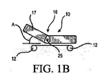
システム10は複数のキャスタ12を具えており、一またはそれ以上のブレーキ14によって、それぞれ係止できる。システム10は、また、フレーム16を具える。フレーム16は、例えば、ベッドとベッドに支持されている患者を上下動させる高さ調節可能なフレームなど、任意の適切なフレームである。例えば、フレーム16は、例えば、病院のベッドフレーム又は、長期療養ベッド用フレームなどのベッドフレームであってもよい。また、例えば、フレーム16は、ほぼ水平な位置と、傾斜した位置の間で選択的に調整可能であるベッドフレームであってもよい。例えば、患者の身体の上側部分に対応するフレーム16の上側部分(例えば、ベッドフレームの背もたれ又は胴体部分)を、選択的に立てることができ、フレーム16の上側部分が水平面から傾く(例えば、患者の身体の上側部分が、例えば、水平位置に維持することが不適切である患者用になど)ようにしてもよい。図1Bに概略的に示すように、フレーム16の上側部分17が、適切な角度「A」で水平位置から、例えば、約20度乃至40度、又は約30度、傾いている。一実施例では、システム10は複数の患者支持セクション(例えば、頭部/背部置きセクション、座セクション、脚部セクション、及び足セクション)を、及び/又はベッドフレーム16の対応する複数のセクションを有するベッド又はマットレスであってもよく、一またはそれ以上又はすべてのこれらセクションは、互いに対して調整可能に移動することができ、したがって、例えば、背もたれセクションを回動させ、ほぼ水平位置から、ほぼ垂直座位置間で、また、これらの間の様々な傾斜角度に回動させることができる。別の実施例では、システム10は、患者を支持するための複数の膨張可能なセル、及び/又は、複数の膨張可能なベッド部分を伴う膨張可能なマットレスを具えていてもよい。図1Aを参照すると、システム10は、また、上側及び下側位置及び/又は中央位置の間で可動である第1のサイドレールセット18(例えば、パネル)を具えていてもよい。システム10は、また、システム10の両側に配置した第2のサイドレールセット20を具えていてもよい。例えば、一またはそれ以上のサイドレール20は、システム10の患者の頭部側端部(例えば、システム10が病院のベッド、又は、上述した同様の施設のベッドである場合)に配置することができる。サイドレール20は、また、下側位置と、図1Aに示すような上に持ち上げた位置との間で可動である。一実施例では、サイドレール20は、持ち上げた最上位置、中央/中央に持ち上げた位置、及び、下側位置の間で可動であってもよい。サイドレール18と20は、例えば、システム10の上側表面上に患者を安全に固定し維持するために使用することができる。
The
システム10は、ヘッドボード22とフットレスト24を具えていてもよい(例えば、システム10が病院のベッド又はその他の同様のタイプの病院設備、または、例えば長期療養又は物理療法リハビリテーション用の設備である場合)。ヘッドボード22とフットレスト24は、ほぼ静止している(例えば、可動又は設定可能でない)。システム10が可動であり、及び/又は、設定可能なヘッドボード及び/又はフットレストを具えていることも意図されている。
The
システム10は、電気式、液体駆動式、及び/又は空気圧駆動式のアクチュエータ25と27を具える。例えば、アクチュエータ25及び27は、フレーム16及び/又はサイドレール18と20の一部として一体的に設けられていてもよく、あるいはシステム10の一またはそれ以上の部材に外付けされていてもよい。システム10のアクチュエータ25及び27は、システム10の動作を容易にする。例えばアクチュエータ25及び27は、システム10の高さ、及び/又はサイドレール18及び/又はサイドレール20の位置を調節するよう作動する。例えば、図1Bに示すように、アクチュエータ25は、システム10の傾きを選択的に制御し、上側部分17を水平面(例えば、ほぼフラットな床)から所望の角度「A」になるように移動させる。アクチュエータ25及び27は、設備の調整に適した任意のアクチュエータである。別の例示的実施例では、アクチュエータ25(例えば、ポンプ、排気及び/又はバルブアクチュエータ)が、マットレスの一またはそれ以上の膨張可能なセル及び/又は膨張可能な部分の膨張及び/又は収縮を制御することができる。
The
システム10は、システム10とその部品の位置及び/又は特性を検出する複数のセンサ29を具える。例えば、センサ29はキャスタ12、ブレーキ14、フレーム16、ベッドのサイドレール18及び/又はサイドレール20の位置を検知することができる。一実施例では、一またはそれ以上のセンサ29が、キャスタ12が上昇したか下降したか、ブレーキ14がロックされているあるいはロックが外れた位置及び/又は状態にあるかどうか、ベッドフレーム16の高さ及び/又はベッド又はベッドフレーム16の一またはそれ以上のセクションの位置(例えば、下降した又は上昇した背もたれ部分、シート部分、脚部部分、及び/又は足の部分)、及び、サイドレール18、20の上昇した及び/又は下降した位置を検出するように配置することができる。別の実施例では、センサ29を用いて、マットレス又はその一部(例えば、マットレスの選択的な膨張可能セル、回転するブラダ、背もたれ部分、シート部分、脚部、及び/又は足部分)の、膨張した及び/又は収縮した状態、膨張及び/又は収縮の度合い、膨張及び/又は収縮の速度、マットレス又はカバーを通る空気流量などの、システム10の部品の動作状態又は特徴に関する情報を提供する。センサ29は、例えば、能動トランスデューサ、受動トランスデューサ、圧力センサ、マグネットとホールセンサ、及び/又は双方向センサなどの、システム10の部材の位置及び/又は動作を検知するのに適したデバイスである。センサ29は、システム10の一またはそれ以上の位置に配置して、例えば、医療専門家やその他の付添人に、システム10の構成を確かめるのに使用するデータを提供するための測定値やその他の情報を提供する。例えば、センサ29は、様々な患者に関連するシステム10の適切なあるいは不適切な構成を担当者に通知するのに使用できる出力を提供する。
The
図2は、例示的な表示器デバイス30を示す図である。表示器デバイスは、システム10の構成に関する情報(例えば、センサ29及び/又はその他の源からの出力)を提供するのに適したデバイスである。例えば、図2に示すように、表示器デバイス30は、例えば、病院のベッドの表示器、患者のサポート表示器、患者の操作設備表示器、病院の家具の表示器、患者移動システムの表示器、患者のリフト及び/又はホイストの表示器、または病院又は同様の施設(例えば、物理療法、長期治療、精神的ケア、又は住居に用いる設備)で用いるその他の適切なタイプの表示器、といったシステム10の構成の状態の表示を提供する、コンフィグレーション表示器であってもよい。表示器デバイス30は、ハウジング32(例えば、表示器デバイス用の適切なハウジング又はケース)を具える。ハウジング32はアタッチメント部分34を具えており、これは、別の部品であるか、ハウジング32の一体部品であってもよい。例えば、アタッチメント部分34は、ハウジング32自体の一部としてハウジング32と一体的に形成されている。アタッチメント部分34は、例えば、フック、クランプ、クラスプ、スナップ、マグネット、開口、コネクタ、又は、表示器デバイス30をシステム10の一部に取り付けるための、システム10に装着するように適切に構成されたその他の部材であってもよい。アタッチメント部分34は、フックまたは、システム10の様々な部材の一部を収納するのに十分に広い開口36を具える。例えば、アタッチメント部分34は、フレーム16の一部の幅、システム10に取り付けたレール、フットレスト24の一部、ヘッドボード22の一部、及び/又はサイドレール18及び20の一部に合うような寸法である。アタッチメント部分34は、例えば、システム10の様々な部分の変化する寸法に合うように調整可能であってもよい。例えば、アタッチメント部分34は、調整可能なフックであってもよい。例示的な実施例では、表示器デバイス30とハウジング32は持ち運び可能である。例えば、ハウジング32は、ユーザが手で保持することができ、ユーザの手で容易に持ち運べる又は移動させられるようなサイズである。例えば、ハウジング32は、人の手くらいのサイズであってもよく、ユーザの手より大きなサイズであってもよい(しかし、それでも持ち運び可能である)。一実施例で、ハウジング32がほぼ静止している(例えば、システム10の所定の位置に、ほぼ固定されている)ことも、意図されている。
FIG. 2 is a diagram showing an
表示器デバイス30は、センサ29、及び/又は、コントローラ35及び/又はシステム10に操作可能に接続されている。一実施例では、表示器デバイス30は、表示器デバイス30をセンサ及び/又はコントローラ35に電気的に接続する接続部材を具える。コントローラ35は、例えば、中央処理装置と、入力を受信し出力を生成するその他の適切な部材(例えば、処理ユニット又はその他の適切なタイプの、自動制御を容易にする自動及び/又はコンピュータコントローラ)を具える。コントローラ35は、例えば、フレーム16などのシステム10の一部分、あるいはシステム10のその他の適切な位置に配置することができる。表示器デバイス30、センサ29、及びコントローラ35は、例えば、ワイヤレス接続(例えば、トランシーバを具えるもの)又は、例えば、電気ケーブルなどのケーブルといった、適切な技術で接続できる。例えば、表示器デバイス30とセンサ29は、フレーム16に配置したコントローラ35に電線を介して接続することができる。例えば、表示器デバイス30、センサ29、及びコントローラ35は、ケーブル接続で接続して、システム10近傍に配したその他の設備と潜在的にインターフェースを取る可能性のあるワイヤレスノイズの量を低減できる。また、例えば、表示器デバイス30、センサ29、及びコントローラ35は、センサ29、表示器デバイス30、及びコントローラ35間のリンクを確実に信頼性のあるものにする適切な技術によって接続することができる。
The
ハウジング32は、表示器デバイス30がシステム10を付添人(例えば、医療従事者又はその他の介護者)によって移動でき、介護者にとって便利でありかつ患者が一人になるとき(例えば、患者が休息しているあるいは眠っている間)を見られるようなシステム10の位置に配置できる、適切な構造又はサイズを有する。例えば、表示器デバイス30は、ドアに近い、又はスクリーンあるいはプライバシーを提供するその他のデバイス(例えば、カーテン、デバイダ、又は患者又はその他のシステム10のユーザのプライバシーを提供するその他のデバイス)の前部に対向するシステム10の位置で又はその近傍に配置することができる。また、例えば、表示器デバイス30は、例えば、フレーム16、サイドレール18、サイドレール20、ヘッドボード22、フットレスト24、ハンドル又はシステム10の書の他の適切な位置といった、介護者に見えるシステム10の位置に配置することができる。一実施例では、表示器デバイス30は、フレーム16、サイドレール18、サイドレール20、ヘッドボード22、フットレスト24、ハンドル又はシステム10の露出している脚部のエッジ又は上側面に連結する、ラッチする、吊るすことができる。
The
表示器デバイス30は、一またはそれ以上の光ユニット40を具えていてもよい。光ユニット40は、システム10の構成の状態を示すのに使用される。光ユニット40は、ハウジング32の一体的部分、又は第1ディスプレイ部材42を囲む個別部品である第1表示器部材41と、ハウジング32の前側部分及び/又は後側部分にある第2ディスプレイ部材44(又は、単一ディスプレイ部材、あるいはその他の適切な数のディスプレイ部材)を具える。一実施例では、第1表示器部材41が、LED光源及び/又はその他の光源といった、照明部材として構成されており、表示器デバイス30が動作しているときに明るくなる。例えば、第1部材41は、異なる色を投影するあるいはシステム10の様々な状態に応じた色を点滅して、システム10の状態に関してユーザに明確に通知する、及び/又はアラーム通知/警報を通信する。一実施例では、第1表示器部材41が、一またはそれ以上のディスプレイ部材42、44を囲んで、単一のディスプレイを形成している。一実施例では、ディスプレイ部材42、44が、例えば一またはそれ以上のディスプレイスクリーン及び/又は適切な数のLED、ランプ、又はその他の光学部材及び光源を具える、及び/又は光学部材及び操作を行う人に通知を提供する適切な構成内に配置された照明部材又は表面用の光源として構成することができる。光ユニット40は、また、第2表示器部材50を具えており、これは、ハウジング32の一体的部分であっても、あるいはハウジング32の底部分に配置した別部品であってもよい。第2表示器部材50は、表示器デバイス30の使用中は光ユニット40で生成した光を下側に向けるように構成されている。例えば、一実施例では、第2表示器部材50は、LED光などの発光部材として、あるいはその他の光源として構成されている。一実施例では、ディスプレイ、ディスプレイ部材、第1表示器部材41、及び/又は第2表示器部材50が、発光部材として構成されており、発光し、色の付いた光を投影し、及び/又は光を点滅させて、ユーザにシステム10の状態を通知し、及び/又は警告/アラーム状態を通知する。これらのディスプレイ、ディスプレイ部材、及び/又は第1表示器部材41は、光の投影を調整し、同時に、光を投影し、及び/又は互いに対して独立して光を投影することができる。
The
表示器デバイス30は、入力ユニット46を具えていてもよい。入力ユニット46は、表示器デバイス30のユーザがシステム10及び/又は患者データなどの入力を、例えば、ボタンコンソール、キーパッド、タッチスクリーン、あるいは、触覚、視覚、聴覚、その他入力を提供するのに適した技術に基づいてユーザからのデータを受信するのに適したその他のユニットといった、表示器デバイス30に提供するのに適切なユニットである。
The
上述したように、光ユニット40は、一またはそれ以上の、あるいは複数のLEDs、ランプ、あるいはその他の光学部材と光源を具える。光ユニット40のこれらの光源は、複数のモードで操作できる。例えば、光ユニット40は、システム10の適切な及び/又は不適切な構成(例えば、患者に適切なステータス、又は、患者に不適切なステータス)を表示するように操作できる。例えば、光ユニット40は、一またはそれ以上のLEDs、ランプ、又はその他の光学部材と光源で形成できる。また、例えば、光ユニット40は、例えば、赤、オレンジ色、黄色、緑、青、紫、及び白を含む複数の異なる色など、適切な波長の光を生成できる。例えば、光ユニット40は、緑、黄色、琥珀色、及び/又は赤色を含む複数の光を具える。この光は、点滅させることもできるし、異なるパターンの光を投光できる。
As mentioned above, the
光ユニット40は、例えば、四角形パターン、円形構造、直線構造、ストライプ構造、及び/又は多角形状といった、適切な形状又は構造にすることができる。光ユニット40は、少なくとも一の光学部材から下側に光を向ける(部材50から離れる方など、表示器デバイス30の縦方向に対して)ように構成した、一またはそれ以上のLEDs、ランプ、光学部材、又は光源を具えていてもよい。光ユニット40は、表示器デバイス30の側部から横方向において水平方向に、表示器デバイス30から上側に、表示器デバイス30から前側に、表示器デバイス30から後ろ側に、表示器デバイス30から対角線方向に、あるいは表示器デバイス30からその他の方向に、光を向けるように構成した、一またはそれ以上のLEDs、ランプ、光学部材、又は光源を具えていてもよい。
The
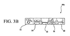
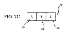
図3Aは、表示器デバイスの例示的実施例を示す。表示器デバイス30aは、表示器デバイス30とほぼ同様である。第2のディスプレイ部材44aと、入力ユニット46aを具えており、これらは第2のディスプレイ部材44と入力ユニット46と、それぞれ同様である。表示器デバイス30aは、ベッド用の例示的表示器デバイスである(例えば、病院、物理療法センター、長期療養設備、住宅、精神病施設、リハビリテーションセンター、及び/又は、その他のベッド用表示器デバイスを提供するのに適した場所)。図3Bに示すように、第2ディスプレイ部材44aは、ブレーキがかかったとき(例えば、ブレーキ14がかかったとき)に光を発するブレーキ表示器52、サイドパネルが立ち上がっているとき、及び/又は下がっているとき(例えば、サイドレール18及び/又はサイドレール20が立ち上がっているとき)に光を発するサイドパネル位置表示器54、ベッド/システム10が立ち上がった位置及び/又は最も下がった位置(例えば、フレーム16が最も高い及び/又は最も低い位置にあるとき)に光を発するベッド高さ表示器56、システム10がユーザが出入りする及び/又はシステム10から降りている構成にあるときに、(例えば、システム10がベッドである場合、患者の出入り表示器58は、例えば、フレーム16が最も下の位置にあり、サイドレール18,20が下りた位置にある、患者がベッドを離れるのに適した時間であること)、あるいは患者が実際にシステム10に出入りする(例えば、センサ29が圧力センサ又は患者がシステム10に出入りすることを検出するのに適したその他のセンサであることを表示する)光を発する患者の出入り表示器58、及び、フレーム16が所定のスレッシュホールドを超えて角度の付いた構成である(例えば、患者の身体の上側部分に対応するフレーム16の部分が、水平面から例えば、30度、35度、25度、または20度といったスレッシュホールド角度より大きい角度が付いている場合)ときを表示する背もたれ傾斜表示器59(例えば、ベッド傾斜表示器)、を具えていてもよい。ブレーキ表示器52、サイドパネル位置表示器54、ベッド高さ表示器56、患者の出入り表示器58、及び/又は背もたれ傾斜表示器59は、システム10の構成可能な各部材の状態の表示を担当者(例えば、看護師又はその他の介護者)に提供する(患者やシステム10の他のユーザの活動に関して)。ブレーキ表示器52、サイドパネル位置表示器54、ベッド高さ表示器56、患者の出入り表示器58、及び/又は背もたれ傾斜表示器59は、一またはそれ以上のセンサ29によって検知したシステム10の構成、及び以下に述べるような入力ユニット46aへの患者のタイプの入力に基づいて、出力を提供できる。その他の実施例では、表示器デバイス30aは更に、マットレスの膨張及び/又は収縮表示器を具えており、ユーザに、マットレスの一又はそれ以上の部分(例えば、マットレスのシート部分)におけるマットレスの圧力の表示、あるいは、一またはそれ以上のマットレスの部分の膨張/収縮率の表示を提供することができる;患者の寝返り表示器は、寝返りブラダーが患者の寝返りを補助するように駆動される時を通知する;及び/又は、マットレス(低エアロスマットレスなど)又はカバーを通る空気流率を決める空気流表示器;を具えていてもよい。
FIG. 3A shows an exemplary embodiment of a display device. The
図3Cに示すように、入力ユニット46a、例えばユーザインターフェースは、第1入力デバイス60と、第2入力デバイス62と、第3入力デバイス64を具える。入力デバイス60、62、64は、例えば、プッシュボタンスイッチ、ダイアル、レバー、又はタッチスクリーンデバイスなど、ユーザが情報を入力ユニット46aへ入力できる適切なタイプのスイッチである。第1入力デバイス60は、システム10が異なる配置又は位置間で移動できない場合にシステム10のパラメータを設定するのに使用できる(例えば、システム10が、実質的に静止している場合、例えば、システム10が患者を収容するベッドである場合)。例えば、第1入力デバイス60は、すべてのユーザ又は患者に適用できる状態(例えば、ユニバーサル設定、全患者タイプの設定など)に対して稼動することができる。例えば、第1入力デバイス60が稼動すると、表示器52,54、56、58、及び59はすべて点灯して、適切な状態(例えば、緑)を介護者に表示する、あるいはまったく点灯しない。また、例えば、第1入力デバイス60が稼動すると、ブレーキ表示器52は、ブレーキ14がオフの時に不適切(例えば、赤又は不適切性を示す青、その他の色)として照明する(例えば、ブレーキ表示器52は、ブレーキ14がオンであり、システム10が適切な静止位置において係止されている場合)。
As shown in FIG. 3C, an input unit 46a, such as a user interface, comprises a
第2入力デバイス62は、オペレータがシステム10を、システム10のユーザの第1カテゴリィ又はタイプに適切だと思える構成に設定するのに使用できる。例えば、第2入力デバイス62を用いて、意図的でなくシステム10に入りそうもない患者(例えば、システム10がベッドである場合に、ヒトの手を借りることなくシステム10に入るあるいはシステム10から出るのに十分に安定している患者、例えば、安定した患者タイプ、といった、ほぼ良好又はフェアな身体的条件にあるユーザ)に適切だと思える構成にシステム10を設定することができる。例えば、第2入力デバイス62は、例えば、サイドレール18及び/又はサイドレール20が下がったあるいは係合していない位置にある場合など、システム10の一またはそれ以上の特徴が切り離されている場合でも、適切なベッド構成を表示できる。例えば、第2入力デバイス62が稼動すると、一又はそれ以上のブレーキ14が係止されていない場合(例えば、ブレーキがオフになっている場合、健康なユーザにとってはシステム10から出ることは、不適切に思える)にブレーキ表示器52はが点灯して、不適切な構成(例えば、赤)を表示するが、全てのブレーキ14が係止されている場合は、適切な構成(例えば、緑)を表示する。例えば、第2入力デバイス62が稼動すると、サイドパネル位置表示器54は点灯しない、あるいは、一またはそれ以上のサイドレール18と20がどちらも上がっている又は下がった位置にある場合、点灯して適切な構成(例えば、緑)を表示する。同様に、第2入力デバイス62が稼動すると、ベッド高さ表示器56は点灯しないか、点灯して、フレーム16も上がったあるいは下がった位置にあるときに、適切な構成(例えば、緑)を表示する。更に、第2入力デバイス62が稼動して、フレーム16が上がった位置にあるときに、ベッド高さ表示器56が点灯して、不適切な構成(例えば、赤)を表示することも考えられる。また、例えば、第2入力デバイス62が稼動すると、患者の出入り表示器58が点灯しない、あるいは、システムが健康な患者がいつでもシステム10に入る、又は、システム10から降りるのに適切であると判断する適切な構成(例えば緑の点灯)を続ける。更に、例えば、第2入力デバイス62が稼動すると、背もたれ傾斜表示器59が点灯しない、あるいは、健康な患者にとって図1Bに示す適切な傾斜角度「A」であることが適切であると判断する、適切な構成(例えば、緑の点灯)を続ける。
The
第3入力デバイス64により、オペレータは、通常高レベルの不安定性及び不確実性(例えば、不安定な患者タイプ)に関連するユーザ用にシステム10を構成することができる。例えば、第3入力デバイス64は、他のユーザよりも意図することなく比較的システム10から出やすいユーザ、あるいは、人の手を借りずにシステム10に入るあるいはシステム10から出ることができる非常に不安定なユーザが使用するシステム10を構成できる。第3入力デバイス64で稼働させた設定では、システム10は、システム10のほとんどのあるいはすべての特徴が係合されている(例えば、システム10内又はシステム10上にユーザを維持するように設計されたシステム10のすべての特徴が、例えば、直立して係止された位置にあるサイドレール18とサイドレール20などに係合されている)場合にのみ、適切な構成にあると考えられる。例えば、システム10がベッドである場合、患者をベッドに維持するように設計されたシステム10のすべての特徴は、第3入力デバイス64を駆動するオペレータに基づいて駆動することができる。したがって、第3入力デバイス64が駆動されると、ブレーキ14がオンであるときにブレーキ表示器52が適切である(例えば、緑)と点灯するが、ブレーキ14がオフであるときは、不適切である(例えば、赤)と点灯し、サイドパネル位置表示器54は、サイドレール18と20が直立位置にあるとき、適切である(例えば、緑)と点灯し、一またはそれ以上のサイドレール18と20が係合が外れている、あるいは下降した位置にあるとき、不適切である(例えば、赤)と点灯し、ベッド高さ表示器56は、フレーム16が最も下降した位置にあるときに適切である(例えば、緑)と点灯し、フレーム16が最も下降した位置以外の位置にあるとき、不適切である(例えば、赤)と点灯し、患者の出入り表示器58は、一またはそれ以上のセンサ29が、患者がシステム10から出ているあるいは出てしまったことを検出した時はいつでも、不適切であると点灯する。更に、第3入力デバイス64が稼動すると、背もたれ傾斜表示器59は、角度「A」が所定の値(例えば、約30度、約25度、約35度、又は約20度)と同じかそれより大きい場合に、適切である(例えば、緑)と点灯し、角度「A」が所定の値以下である場合に、不適切である(例えば、赤)と点灯する(例えば、平坦な位置ではなく傾斜した位置に患者が維持されていることを介護者に表示する。)。
The
第1入力デバイス60、第2入力デバイス62、及び第3入力デバイス64は、コントローラ35、表示器デバイス30a、及び/又は、センサ29と操作可能に関係している、及び/又は、これらと共働して稼動し、例えば、LEDs、ランプ、あるいはその他の光学部材又は光ユニット光源40、及び第2ディスプレイ部材44を点灯させて、ベッドが第1入力デバイス60、第2入力デバイス62、及び/又は、第3入力デバイス64のそれぞれの基準に適切に合致した構成にあるかどうかを表示する。例えば、システム10が適切に構成されていると思われる場合、光ユニット40は第1モードで点灯する(例えば、光ユニット40は、緑、白、紫、青、又はその他の所定の色で点灯するか、途切れることなく点灯する)。また、例えば、システム10が不適切に構成されていると考えられる場合は、光ユニット40は第2モードで点灯する(例えば、光ユニット40は、別の色、例えば、赤、オレンジ色、黄色、又はその他の所定の色で点灯するか、点滅する)更に、例えば、光ユニット40は、介護者にシステム10の構成のステータスについて直感的に通知する態様で点灯するように設計することもできる(例えば、照明の赤の点滅モードは、直感的に、介護者にシステム10の不適切な構成を通知するものであり、一方、安定した緑の照明モードは、介護者にシステム10の適切な構成を直感的に通知することができる)。表示器デバイス30aは、更に、音響特性を具えており、適切な状況にある介護者に更なる通知を提供することができる。例えば、システム10が精神病治療施設で使用される場合、表示器デバイス30aは、介護者にシステム10の不適切な構成を通知する音響特性を具えていてもよい(例えば、介護者に不適切な構成を通知する高ピッチの音響警告)。
The
表示部材42、44、ブレーキ表示器52、サイドパネル位置表示器54、ベッド高さ表示器56、患者の出入り表示器58は、及び/又は、背もたれ傾斜表示器59は、光ユニット40に関して上述したものと同様に点灯することができる。例えば、ブレーキ表示器52は、一またはそれ以上のブレーキ14がかかったときに点灯する。また、例えば、サイドパネル位置表示器54は、サイドレール18及び/又は20が上がった時に点灯する。更に、例えば、ベッド高さ表示器56は、最も下降した位置にシステムがあるときに点灯するようにしてもよい。更に、例えば、患者の出入り表示器58は、システム10が、患者がシステム10に移動する又はシステム10から離れるのに適切な構成にあると考えらえる場合に点灯するようにしてもよい。また、例えば、ブレーキ表示器52、サイドパネル位置表示器54は、ベッド高さ表示器56、患者の出入り表示器58、及び/又は、背もたれ傾斜表示器59は、様々な色で点灯するタイプのものであってもよい(例えば、これらの表示器は、システム10の関連する特徴が入力したあるいは表示した構成にないときには、赤で点灯し、あるいは、システム10の関連する特徴が、入力したあるいは表示した構成に合致する時は緑に点灯する)。更に、例えば、ブレーキ表示器52、サイドパネル位置表示器54、ベッド高さ表示器56、患者の出入り表示器58、及び/又は、背もたれ傾斜表示器59は、ベッドがこれらの表示器に関連する構成に駆動されたと検出されたときにのみ点灯するように構成してもよい。点灯している表示器52、54、56、58及び/又は、59と合わせて、光ユニット40は、これらの表示器の点灯に基づいて介護者に一貫した通知を提供するように点灯させることができる(例えば、表示器デバイス30のある部分に配置した光ユニット40は、システム10から離れた有意な距離に位置する介護者に通知するように点灯させることができる)。
The
図4は、例えば、安定した患者(例えば、システム10の位置を維持することができる比較的健康な患者)などのユーザに適切であると考えらえるシステム10の例示的構成を示す。表示器デバイス30及び/又は表示器デバイス30aに加えて、システム10を利用している患者用に配置した第2表示器デバイス130を設けるようにしてもよい。したがって、患者は表示器デバイス130を用いて、表示器デバイス30と表示器デバイス30aについて上述したものと同様に、システム10を制御し及び/又はシステム10に入力することができる。また、例えば、患者は、表示器デバイス30と表示器デバイス30aに関して上述した特徴のすべてではないが、代わりにシステム10のいくつかの特徴を制御するように構成した別のコントローラを具えていてもよい。更に、例えば、患者に表示器デバイス又はシステム10を制御するコントローラを提供しなくともよい。
FIG. 4 shows an exemplary configuration of a
図4に記載した構成では、光ユニット40は適切な構成(例えば、適切なベッド構成)を表す緑色光を発する。例えば、下降したにあるフレーム16、かかっているブレーキ14、及びサイドレール18とサイドレール20の少なくとも一方が下降位置にある。また、例えば、表示器デバイス30及び/又は、表示器デバイス130は、サイドレール18とサイドレール20の一方のみ(例えば、サイドレール18とサイドレール20の各々)が下降しており、他方が上昇している場合、システム10の一方の側部にあるサイドレール又はサイドパネルのみが下降している、サイドレール18とサイドレール20の両方が下降している、あるいは、システム10のすべての側部にあるすべてのサイドレールが下降している場合(例えば、システム10が下降位置にある場合)、システム10が適切な構成にあることを表示する。また、例えば、表示器デバイス30が、システム10がこの構成にあるときに、医療従事者あるいは、看護師などの介護者に、患者が所定の構成を開始したことの通知として働く警告音を発するように構成して、患者のシステム10の使用をモニタ出来るようにしてもよい。このように、表示器デバイス30(及び/又は、表示器デバイス30aと表示器デバイス130)は、例えば下降する又は動作が停止している構成にセットする(例えば、入力ユニット46を用いて)ことによって、システム10を、システム10の一又はそれ以上の特性が、機能性を提供することができる。特に、この設定によって、ユーザ(例えば、身体的に可能なユーザ)は、サイドレール18及び/又はサイドレール20の一又はそれ以上が、表示器30が通知(例えば、上述したような照明を提供するあるいは警告を出すことによる不適切な構成の通知)を提供することなく下降した時に、起き上がる又はシステム10の上に起きることができる。更に、システム10は比較的不安定である、あるいは身体的にできない患者を、システム10から降りることを実質的に防止する(例えば、表示器デバイス30を介して介護者に通知を提供することによって)ことに役立つ。
In the configuration described in FIG. 4, the
図5は、図4に示すシステムと同様の構成を示すが、表示器デバイス30が比較的不安定な患者(例えば、比較的不健康である、あるいは身体的能力がない)用に設定されている。例えば、この構成は、第3入力デバイス64が稼動しているシステム10の構成に関連している。この設定では、光ユニット40が警告光を発する(例えば、システム10内に身体的に安定していない患者がいるため、介護者に一またはそれ以上のサイドレール18及び/又はサイドレール20が下降位置にあることを通知する赤色又は琥珀色の発光)。表示器デバイス30は、ブレーキ14がかかったとき、フレーム16が下降位置にあるとき(例えば、最も低い位置)、サイドレール18とサイドレール20の多数が上昇位置にあるとき(例えば、4つのサイドレール18とサイドレール20のうちの少なくとも3つ)、出入りアラームが駆動した時(例えば、表示器デバイス30の一部、フレーム16、及び/又はシステム10のその他の適切な部分として設けられている音響警告デバイス)に、光ユニット40から緑色光を発光する。例えば、システム10が病院のベッドなどのベッドである場合、表示器デバイス30は、例えば、システム10が身体的に不安定な患者用の適切な設定にあるときに、光ユニット40から緑色光の身を発光させる(その患者にとって稼働させることが適切であるすべての適切な特徴を稼動させる)。
FIG. 5 shows a configuration similar to the system shown in FIG. 4, but the
図6は、例示的なシステム10bを示す。システム10bは、病院又はその他の療養施設における、例えば、患者を持ち上げるシステム又は患者のホイストといった、ユーザの動きを支援するシステムである。システム10bは、例えば、ベッド又はその他の施設の一部へ患者を入れるあるいはこれから出す支援用の持ち上げシステムであってもよい。
FIG. 6 shows an
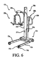
例示的なシステム10bは、シャーシ72bに装着できるマスト70bを具える。シャーシ72bは、システム10bを安定化させる複数のシャーシ脚部73b(例えば、安定化脚部)を具えている。複数のキャスタ74bがシャーシ72bの、例えば脚部73bの遠位端に装着されており、ユーザ及び/又は介護者の所望するようにシステム10bを移動させることができる。各キャスタ74bにブレーキ76bが設けられており、選択的にキャスタ74bをロックして、システム10bの移動を実質的に防止できる。また、患者インターフェース78b(例えば、患者サポートインターフェース)がマスト70bに装着されており、移動中に患者をシステム10bに固定するのに使用できる(例えば、患者を保持するストラップ又はその他のアタッチメントを介して)。表示器デバイス30bは、部材80bあるいはハンドルといったシステム10bの適切な部分に取り付けることができる。表示器デバイス30bは、例えば、マスト70b、シャーシ72b、又は患者のインターフェース78bといった、システム10bのその他の部分に設けるようにしてもよい。システム10bは、更に、一またはそれ以上のアクチュエータ27b、センサ29b、及びコントローラ35bを具えていてもよい。これらは、アクチュエータ27、選択的に29、及びコントローラ35とほぼ同様に作動する。
An
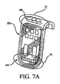
図7Aは、例示的な表示器30bを示す。表示器30bは、第2表示部材44aとほぼ同様の第2表示部材44bと、入力ユニット46aとほぼ同様の入力ユニット46bを具える。図7Bに示すように、第2ディスプレイ部材44bは、第2表示部材44aの表示器とほぼ同様の複数の表示器を具える。例えば、第2表示部材44bは、ブレーキがかかったとき(例えば、ブレーキ76bがかかったとき)に発光するブレーキ表示器52bと、患者が患者インターフェース78bに載せられたときに発光する、インターフェース積載表示器54bと、マスト70bが延びる、あるいは所定の高さに上昇したとき(例えば、マスト70bがある高さ、例えば、200cm又はそれ以上、180cm又はそれ以上、210cm又はそれ以上、又は220cm又はそれ以上まで上昇したとき)に発光するマスト上昇表示器56b(例えば、マスト高さ表示器)と、シャーシ脚部73bが閉じた位置にあるとき(例えば、シャーシ脚部73bが閉じている及び/又はシステム10bの縦方向を更に、安定化させる係止位置にある)に発光するシャーシ脚部係合表示器58bと、システム10bが所定の時間(例えば、約5分、または約10分)静止位置にあるが、ブレーキ76bは作動していない時に発光する停止時間表示器59bと、患者インターフェース78bがマスト70bに適切に接続されているとき(例えば、患者インターフェース78bとマスト70bの間にしっかりした信頼性のある接続がなされているとき)に発光するインターフェース接続表示器61bと、を具える。例えば、インターフェース接続表示器61bは、スリング、安全ベルト、または患者を患者インターフェース78bに固定するのに用いられる他の要素の取り付けが正しいか(例えば、適切の表示を点灯)正しくないか(例えば、不適切の表示を点灯)を示してもよい。また、例えば、第2表示部材44bは、システムの電源10bのバッテリィレベル状態に基づいて点灯する(例えば、バッテリィ電力が十分なときは適切の表示を点灯し、および/または、バッテリィ状態が低いときは不適切の表示を点灯する)バッテリィ状態表示器63bを具えてもよい。ブレーキ表示器52b、インターフェース積載表示器54b、マスト上昇表示器56b、シャーシ脚部係合表示器58b、停止時間表示器59b、インターフェース接続表示器61b、および/またはバッテリィ状態表示器63bは、システム10bの構成可能な各部材の状態の表示を担当者(例えば、看護師又はその他の介護者)に提供する。ブレーキ表示器52b、インターフェース搭載表示器54b、マスト上昇表示器56b、シャーシ脚部係合表示器58b、停止時間表示器59b、インターフェース接続表示器61b、および/またはバッテリィ状態表示器63bは、1またはそれ以上のセンサ29bが検知したシステム10bの構成と、入力ユニット46bに入力された患者タイプとに基づいて出力を提供する。
FIG. 7A shows an
図7Cに示すように、入力ユニット46bは、第1入力デバイス60b、第2入力デバイス62b、及び第3入力デバイス64bを具え、これらは入力ユニット46aの入力デバイスとほぼ同様である。第1入力デバイス60と同様に、第1入力デバイス60bは、システム10bが異なる位置又はポジション間で動いていないとき(例えば、システム10bがほぼ静止しているとき)にオペレータがシステム10bのパラメータを設定するのに使用できる。例えば、第1入力デバイス60bが、全てのユーザ又は患者に適用可能な場合用に稼働することができる(例えば、ユニバーサル設定、あるいは全患者タイプ設定)。例えば、第1入力デバイス60bが稼動すると、表示器52b、54b、56b、58b、59b、61b、及び63bは、すべて発光して、介護者に適切な状態を表示する(例えば、緑)か、あるいは、全く発光しなくともよい。また、例えば、第1入力デバイス60bが稼動すると、ブレーキ76bがオフの時にブレーキ表示器52bが不適切である(例えば、赤、又は不適切性を表すその他の色)として発光する、(及び、例えば、ブレーキ表示器52bは、ブレーキ76bがオンであり、システム10bが実質的に静止した位置に係止しているときに、適切であると発光する)ようにしてもよい。更に、例えば、バッテリィ状態表示器63bは、バッテリィ又はシステム10bの電源が低い場合に発光して、バッテリィ又はシステム10bの電源が電力を保つのに十分であるときに適切であると発光してもよい。
As shown in FIG. 7C, the
第2入力デバイス62bは、第2入力デバイス62と第2表示部材44aの表示器と同様に、表示器52b、54b、56b、58b、59b、61b、及び/又は63bと共働する。例えば、第2入力デバイス62bが稼動すると(例えば、ほぼ良好である、あるいは身体状態がよいユーザ)、表示器52b、54b、56b、58b、59b、61b及び/又は63bが、通常、適切な構成を維持する(例えば、緑又は適切性を表すその他の色を発光する)、又は、多くの場合以外で、全く発光しない。例えば、第2入力デバイス62bが稼動すると、ブレーキ表示器52bは不適切であると発光し(例えば、赤又は不適切性を表すその他の色)、全ブレーキ76bがオフになると、マスト上昇表示器56bが、所定の長さ又は高さを超えると不適切であると発光し(例えば、高さが200cmを超える、220cmを超える、240cmを超える、など)、一またはそれ以上のセンサ29bが信頼性のある接続がなされていなかったことを検出すると、インターフェース接続表示器61bが不適切であると発光する。また、例えば、バッテリィ状況表示器63bは、バッテリィ又はシステム10の電源が低いときに不適切であると発光し、バッテリィ又はシステム10bの電源が十分に電力を保持している場合は、適切として発光する。
The second input device 62b cooperates with the indicators 52b, 54b, 56b, 58b, 59b, 61b, and / or 63b in the same manner as the indicators of the
第3入力デバイス64bは、第3入力デバイス64と第2表示部材44aの表示器と同様に、表示器52b、54b、56b、58b、59b、61b、及び/又は63bと共働する。例えば、第3入力デバイス64bが稼動すると(例えば、身体状態がよくないユーザ用に)、表示器52b、54b、56b、58b、59b、61b及び/又は63bは、いくつかの場合にのみ適切な構成として発光する(例えば、緑又は適切性を表すその他の色を発光する)。例えば、第3入力デバイス64bが稼動すると、ブレーキ表示器52bは適切であると発光し(例えば、緑又は適切性を表すその他の色)、全ブレーキ76bがオンになると、インターフェース積込表示器54bが発光して、患者が患者インターフェース78bに乗っているときは常に介護者に警告を出し(例えば、黄色、又は特定の注意が払われるべきとのことを表示するその他の適切な色)、マスト上昇表示器56bが、所定の長さ又は高さを超えると不適切であると、発光し(例えば、高さが160cmを超える、180cmを超える、又は200cmを超える、など)、停止時間表示器59bは、システム10bが静止し続けているが、所定の時間より少ない時間(また、例えば、1分後、2分後、4分後、5分後、10分後、あるいはその他の所定の時間インターバルの後、発光が適切から不適切に変わるようにしてもよい)、及び、一またはそれ以上のセンサ29bが信頼性のある接続がなされていなかったことを検出すると、インターフェース接続表示器61bが不適切であると発光する。また、例えば、第3入力デバイス64bが稼動すると、シャーシ脚部係止表示器58bは、シャーシ脚部73bが閉じているか、あるいはシステム10bの安定性を上げる位置で係止されているときに、適切であると発光する。第3入力デバイス64bが稼動している時のシステム10bのほとんどの、あるいはすべてのその他の構成について、一またはそれ以上の表示器52b、54b、56b、58b、59b、61b、及び/又は63bは、不適切な構成を表示するべく発光し(例えば、比較的弱い又は虚弱な患者に関連するより多く要求するパラメータを反映する)、光ユニット40も、不適切な構成を同様に表示するように発光する。また、例えば、バッテリィ状況表示器63bは、バッテリィ又はシステム10bの電源が低いときに不適切であると発光し、バッテリィ又はシステム10bの電源が十分に電力を保持している場合は、適切として発光する。発光している表示器52b、54b、56b、58b、59b、61b、及び/又は63bと共に、光ユニット40も発光して、表示器の発光に基づいて介護者に一貫した通知を提供する(例えば、表示器デバイス40bの任意の部分に配置された光ユニット40が発光して、システム10bから有意に離れて位置している介護者に通知を提供する)。
The
開示されている例示的なデバイスとシステムは、例えば、システムのすぐ近くにいない医療従事者や付添人などの介護者が適切に見ることができる、システム10の様々な位置に配置できる表示器デバイス30を提供できる。開示されている例示的デバイスとシステムは、また、システム10の一又はそれ以上の特徴が稼動していない状態にあるとき(例えば、一またはそれ以上のサイドレール18又はサイドレール20が下降していて、患者が意図することなくシステム10に入る又はシステム10から出ることができるとき、あるいは、フレーム16が下降した又は最も下側の位置にあるとき)に、適切性を表示する設定機能を提供する(例えば、患者の健康などのユーザの属性に基づいて)。また、例えば、システム10は様々なパラメータの個々のモニタリングと共に、システムの全ステータスのモニタリングと表示を提供する、一体化通知システムを提供できる。
The disclosed exemplary devices and systems are display devices that can be placed at various locations in the
システム10の様々な例示的実施例の機能性に応じて、適切なシステム特性の数又は組み合わせを、開示した例示的システム10と合わせて提供できることが意図されている。例えば、システム10は、様々なタイプ又はカテゴリィの患者にあった複数の構成を有していてもよい。
Depending on the functionality of the various exemplary embodiments of the
上述した例示的特徴を、互いに適切な態様で組み合わせることが意図されている。様々な変形及び変更を、開示した方法と装置に行い得ることは、当業者には自明である。開示した方法及び装置の明細書と実施を考慮して、その他の実施例は当業者には自明である。明細書と開示した実施例は、例示のためと考えられ、発明の範囲は、特許請求の範囲に記載されている。 It is intended that the above exemplary features be combined in an appropriate manner with each other. It is self-evident to those skilled in the art that various modifications and modifications can be made to the disclosed methods and devices. Other embodiments will be apparent to those of skill in the art in view of the disclosed methods and device specifications and practices. The specification and the disclosed examples are considered for illustration purposes, and the scope of the invention is described in the claims.
Claims (12)
当該患者ハンドリング装置の構成を検出する一又はそれ以上のセンサと;
当該一またはそれ以上のセンサと動作可能に接続された表示器デバイスとを具え、当該表示器デバイスが:
患者のタイプの情報を入力できるユーザインターフェースであって、前記患者のタイプの情報が、患者が移動できる度合および/またはレベルに関する安定した患者タイプまたは不安定な患者タイプであるユーザインタフェースと;
前記入力した患者のタイプの情報と、前記一またはそれ以上のセンサによって検出した患者ハンドリング装置の構成とに基づいてステータス通知を発する表示器と、を具え、
得られたステータスおよび/またはステータス通知が、患者にとって適切なステータスまたは患者にとって不適切なステータスであり、
前記患者ハンドリング装置が、さらに、複数のキャスタと、当該複数のキャスタを選択的に制動する1以上のブレーキと、を具え、
少なくとも1つの前記センサは、前記複数のキャスタが前記1以上のブレーキによりロックされているかどうかを検出し、
前記患者ハンドリング装置がベッドであり、前記一またはそれ以上のセンサがベッド出入りセンサを含み、
前記表示器が、前記ベッドのフレームが最も低い位置にあることに基づいて患者がベッドを離れることが適切であるかを示す患者出入り表示器を含む、ことを特徴とする患者ハンドリング装置。 In the patient handling device:
With one or more sensors that detect the configuration of the patient handling device;
With the one or more sensors and an operably connected indicator device, the indicator device is:
A user interface that allows input of patient type information, wherein the patient type information is a stable patient type or an unstable patient type with respect to the degree and / or level of movement of the patient;
It comprises an indicator that issues a status notification based on the entered patient type information and the configuration of the patient handling device detected by the one or more sensors.
The obtained status and / or status notification is a status appropriate for the patient or inappropriate for the patient.
The patient handling device further comprises a plurality of casters and one or more brakes that selectively brake the plurality of casters.
At least one of the sensors detects whether the plurality of casters are locked by the one or more brakes.
The patient handling device is a bed and the one or more sensors include a bed entry / exit sensor.
A patient handling device comprising the indicator indicating whether it is appropriate for the patient to leave the bed based on the lowest position of the bed frame.
Applications Claiming Priority (3)
| Application Number | Priority Date | Filing Date | Title |
|---|---|---|---|
| US201562263032P | 2015-12-04 | 2015-12-04 | |
| US62/263,032 | 2015-12-04 | ||
| PCT/EP2016/079689 WO2017093549A1 (en) | 2015-12-04 | 2016-12-02 | Indicator device |
Publications (2)
| Publication Number | Publication Date |
|---|---|
| JP2019503822A JP2019503822A (en) | 2019-02-14 |
| JP6968085B2 true JP6968085B2 (en) | 2021-11-17 |
Family
ID=57482422
Family Applications (1)
| Application Number | Title | Priority Date | Filing Date |
|---|---|---|---|
| JP2018548282A Active JP6968085B2 (en) | 2015-12-04 | 2016-12-02 | Display device |
Country Status (10)
| Country | Link |
|---|---|
| US (1) | US10932969B2 (en) |
| EP (1) | EP3383337A1 (en) |
| JP (1) | JP6968085B2 (en) |
| AU (1) | AU2016362009B2 (en) |
| BR (1) | BR112018011315B1 (en) |
| CA (1) | CA3007386C (en) |
| HK (1) | HK1254777A1 (en) |
| MX (1) | MX2018006783A (en) |
| SG (2) | SG10202005525QA (en) |
| WO (1) | WO2017093549A1 (en) |
Families Citing this family (12)
| Publication number | Priority date | Publication date | Assignee | Title |
|---|---|---|---|---|
| US9999375B2 (en) * | 2015-04-09 | 2018-06-19 | Stryker Corporation | Location detection systems and methods |
| JP6284574B2 (en) * | 2016-05-20 | 2018-02-28 | ミネベアミツミ株式会社 | Biological information monitoring system |
| CA3124450A1 (en) * | 2018-12-21 | 2020-06-25 | Stryker Corporation | User module for a patient support apparatus |
| US20200268580A1 (en) * | 2019-02-26 | 2020-08-27 | Hill-Rom Services, Inc. | Medical equipment status indicator |
| EP3744299B1 (en) * | 2019-05-30 | 2023-07-26 | Hill-Rom Services, Inc. | Patient support interface device |
| JP7257904B2 (en) | 2019-07-12 | 2023-04-14 | パラマウントベッド株式会社 | Bed operation receiving device and bed device |
| KR102246649B1 (en) * | 2019-09-23 | 2021-04-30 | 주식회사 시스포케어 | Fall-down prevention system for bed |
| KR102351617B1 (en) * | 2019-11-28 | 2022-01-13 | 가톨릭관동대학교산학협력단 | Medical bed for transfering patient |
| US11816978B1 (en) * | 2020-04-01 | 2023-11-14 | JDTC Inc. | System, device, method and program product to provide healthcare at a remote location |
| US11767198B2 (en) * | 2020-04-08 | 2023-09-26 | Liko Research & Development Ab | Sling bars, methods for attaching a subject sling to sling bars, and lift systems using sling bars |
| TWI752521B (en) * | 2020-06-11 | 2022-01-11 | 亞東學校財團法人亞東科技大學 | Bed and method of preventing human body from generating decubitus and detecting human body leaving bed |
| KR102517809B1 (en) * | 2020-12-31 | 2023-04-03 | 광주보건대학산학협력단 | Bed assembly for transfering patient |
Family Cites Families (26)
| Publication number | Priority date | Publication date | Assignee | Title |
|---|---|---|---|---|
| US5349340A (en) * | 1993-01-29 | 1994-09-20 | Hunter Fan Company | Portable patient alerting apparatus |
| US7834768B2 (en) * | 1999-03-05 | 2010-11-16 | Hill-Rom Services, Inc. | Obstruction detection apparatus for a bed |
| US7319386B2 (en) * | 2004-08-02 | 2008-01-15 | Hill-Rom Services, Inc. | Configurable system for alerting caregivers |
| US7690059B2 (en) * | 2005-12-19 | 2010-04-06 | Stryker Corporation | Hospital bed |
| AU2012201414A1 (en) * | 2005-07-08 | 2012-03-29 | Hill-Rom Services, Inc. | Patient Support Apparatus Having Alert Light |
| EP1951111B1 (en) * | 2005-11-07 | 2010-08-11 | Stryker Corporation | Patient handling device including local status indication, one-touch fowler angle adjustment, and power-on alarm configuration |
| EP1965679A4 (en) * | 2005-12-19 | 2012-08-15 | Stryker Corp | Hospital bed |
| US11246776B2 (en) * | 2005-12-19 | 2022-02-15 | Stryker Corporation | Patient support with improved control |
| JP2008282219A (en) | 2007-05-10 | 2008-11-20 | Chudenko Corp | Getting-out-of-bed detecting system, and method |
| US7987069B2 (en) * | 2007-11-12 | 2011-07-26 | Bee Cave, Llc | Monitoring patient support exiting and initiating response |
| US8752220B2 (en) * | 2009-07-10 | 2014-06-17 | Hill-Rom Services, Inc. | Systems for patient support, monitoring and treatment |
| EP2345396B1 (en) * | 2010-01-14 | 2013-05-08 | Hill-Rom Services, Inc. | Person-support apparatus height indicator |
| US8334777B2 (en) * | 2010-02-19 | 2012-12-18 | Hill-Rom Services, Inc. | Patient room and bed management apparatus and system |
| US8432287B2 (en) | 2010-07-30 | 2013-04-30 | Hill-Rom Services, Inc. | Apparatus for controlling room lighting in response to bed exit |
| JP5594768B2 (en) | 2010-08-18 | 2014-09-24 | パラマウントベッド株式会社 | Electric bed operation mechanism |
| US20120215360A1 (en) * | 2011-02-21 | 2012-08-23 | Zerhusen Robert M | Patient support with electronic writing tablet |
| WO2012122002A1 (en) | 2011-03-04 | 2012-09-13 | Stryker Corporation | Sensing system for patient supports |
| WO2013053040A1 (en) * | 2011-10-09 | 2013-04-18 | Chg Hospital Beds Inc. | Illuminable indicator for a bed |
| AU2012339264B2 (en) * | 2011-11-14 | 2017-04-13 | Linak A/S | Castor control system |
| JP5640023B2 (en) * | 2012-01-16 | 2014-12-10 | フランスベッド株式会社 | Hand control device for bed equipment |
| JP2014233490A (en) * | 2013-06-03 | 2014-12-15 | アルプス電気株式会社 | Side fence position detection device, side fence, and bed with side fence |
| EP2862552B1 (en) * | 2013-10-21 | 2017-09-20 | Liko Research & Development AB | Sling bar or lift strap connector having an integrated scale with tilt compensation |
| US9463126B2 (en) | 2014-03-11 | 2016-10-11 | Hill-Rom Services, Inc. | Caregiver universal remote cart for patient bed control |
| JP2017511173A (en) * | 2014-03-13 | 2017-04-20 | ヒレンブランド・マネジメント・カンパニー・エルエルシー | Patient monitoring and relocation system and method |
| US10420687B2 (en) * | 2015-05-12 | 2019-09-24 | Stryker Corporation | Battery management for patient support apparatuses |
| US10629052B2 (en) * | 2015-10-28 | 2020-04-21 | Hill-Rom Services, Inc. | Bed alert condition configuration using a remote computer device |
-
2016
- 2016-12-02 EP EP16805824.6A patent/EP3383337A1/en active Pending
- 2016-12-02 SG SG10202005525QA patent/SG10202005525QA/en unknown
- 2016-12-02 MX MX2018006783A patent/MX2018006783A/en unknown
- 2016-12-02 US US15/780,848 patent/US10932969B2/en active Active
- 2016-12-02 WO PCT/EP2016/079689 patent/WO2017093549A1/en active Application Filing
- 2016-12-02 BR BR112018011315-8A patent/BR112018011315B1/en active IP Right Grant
- 2016-12-02 JP JP2018548282A patent/JP6968085B2/en active Active
- 2016-12-02 AU AU2016362009A patent/AU2016362009B2/en active Active
- 2016-12-02 CA CA3007386A patent/CA3007386C/en active Active
- 2016-12-02 SG SG11201804643PA patent/SG11201804643PA/en unknown
-
2018
- 2018-10-30 HK HK18113823.6A patent/HK1254777A1/en unknown
Also Published As
| Publication number | Publication date |
|---|---|
| US10932969B2 (en) | 2021-03-02 |
| BR112018011315A2 (en) | 2018-12-04 |
| CA3007386C (en) | 2023-12-05 |
| AU2016362009A1 (en) | 2018-06-28 |
| CA3007386A1 (en) | 2017-06-08 |
| HK1254777A1 (en) | 2019-07-26 |
| SG11201804643PA (en) | 2018-06-28 |
| MX2018006783A (en) | 2018-11-09 |
| EP3383337A1 (en) | 2018-10-10 |
| WO2017093549A1 (en) | 2017-06-08 |
| JP2019503822A (en) | 2019-02-14 |
| AU2016362009B2 (en) | 2021-04-01 |
| US20180353358A1 (en) | 2018-12-13 |
| BR112018011315B1 (en) | 2023-04-11 |
| SG10202005525QA (en) | 2020-07-29 |
Similar Documents
| Publication | Publication Date | Title |
|---|---|---|
| JP6968085B2 (en) | Display device | |
| ES2350247T3 (en) | DEVICE FOR THE MINIPULATION OF PATIENTS THAT INCLUDES INDICATION OF LOCAL STATE, REGULATION OF THE ANGLE OF POSITION INCORPORATED OF A SINGLE TOUCH, AND CONFIGURATION OF POWER ALARM. | |
| JP6730327B2 (en) | Patient support device | |
| US10952920B2 (en) | Patient support apparatus having an integrated limb compression device | |
| US10629052B2 (en) | Bed alert condition configuration using a remote computer device | |
| ES2733637T3 (en) | Motorized ambulance stretcher with an automated stretcher control system | |
| CN111148454B (en) | Cradle | |
| US11723821B2 (en) | Patient support apparatus for controlling patient ingress and egress | |
| US11160514B2 (en) | Patient support apparatus with caregiver reminders | |
| US20210106478A1 (en) | Techniques for notifying persons within a vicinity of a patient support apparatus of a remote control function | |
| JP2023080162A (en) | Bed operation reception device and bed device | |
| JP7125361B2 (en) | Structure | |
| CA3124450A1 (en) | User module for a patient support apparatus | |
| EP4184523A1 (en) | Authorization system for integrated feature of support apparatus | |
| US20230157912A1 (en) | Patient Support Apparatus For Sensing And Responding To An Emergency Event | |
| WO2022251199A1 (en) | Patient support apparatus with caregiver reminders | |
| CA3119879A1 (en) | Patient support apparatus with caregiver reminders | |
| CA3119939A1 (en) | Patient support apparatus with caregiver reminders |
Legal Events
| Date | Code | Title | Description |
|---|---|---|---|
| A621 | Written request for application examination |
Free format text: JAPANESE INTERMEDIATE CODE: A621 Effective date: 20191129 |
|
| A977 | Report on retrieval |
Free format text: JAPANESE INTERMEDIATE CODE: A971007 Effective date: 20200819 |
|
| A131 | Notification of reasons for refusal |
Free format text: JAPANESE INTERMEDIATE CODE: A131 Effective date: 20200901 |
|
| A521 | Request for written amendment filed |
Free format text: JAPANESE INTERMEDIATE CODE: A523 Effective date: 20201130 |
|
| A131 | Notification of reasons for refusal |
Free format text: JAPANESE INTERMEDIATE CODE: A131 Effective date: 20210330 |
|
| A521 | Request for written amendment filed |
Free format text: JAPANESE INTERMEDIATE CODE: A523 Effective date: 20210625 |
|
| TRDD | Decision of grant or rejection written | ||
| A01 | Written decision to grant a patent or to grant a registration (utility model) |
Free format text: JAPANESE INTERMEDIATE CODE: A01 Effective date: 20210928 |
|
| A61 | First payment of annual fees (during grant procedure) |
Free format text: JAPANESE INTERMEDIATE CODE: A61 Effective date: 20211026 |
|
| R150 | Certificate of patent or registration of utility model |
Ref document number: 6968085 Country of ref document: JP Free format text: JAPANESE INTERMEDIATE CODE: R150 |