JP6963611B2 - Uplink control information transmission method of terminals in wireless communication systems and devices that support them - Google Patents
Uplink control information transmission method of terminals in wireless communication systems and devices that support them Download PDFInfo
- Publication number
- JP6963611B2 JP6963611B2 JP2019527131A JP2019527131A JP6963611B2 JP 6963611 B2 JP6963611 B2 JP 6963611B2 JP 2019527131 A JP2019527131 A JP 2019527131A JP 2019527131 A JP2019527131 A JP 2019527131A JP 6963611 B2 JP6963611 B2 JP 6963611B2
- Authority
- JP
- Japan
- Prior art keywords
- uci
- pusch
- mapping
- harq
- ack
- Prior art date
- Legal status (The legal status is an assumption and is not a legal conclusion. Google has not performed a legal analysis and makes no representation as to the accuracy of the status listed.)
- Active
Links
Images


Classifications
-
- H—ELECTRICITY
- H04—ELECTRIC COMMUNICATION TECHNIQUE
- H04L—TRANSMISSION OF DIGITAL INFORMATION, e.g. TELEGRAPHIC COMMUNICATION
- H04L1/00—Arrangements for detecting or preventing errors in the information received
- H04L1/004—Arrangements for detecting or preventing errors in the information received by using forward error control
- H04L1/0056—Systems characterized by the type of code used
- H04L1/0067—Rate matching
- H04L1/0068—Rate matching by puncturing
-
- H—ELECTRICITY
- H04—ELECTRIC COMMUNICATION TECHNIQUE
- H04L—TRANSMISSION OF DIGITAL INFORMATION, e.g. TELEGRAPHIC COMMUNICATION
- H04L1/00—Arrangements for detecting or preventing errors in the information received
- H04L1/0001—Systems modifying transmission characteristics according to link quality, e.g. power backoff
- H04L1/0023—Systems modifying transmission characteristics according to link quality, e.g. power backoff characterised by the signalling
- H04L1/0026—Transmission of channel quality indication
-
- H—ELECTRICITY
- H04—ELECTRIC COMMUNICATION TECHNIQUE
- H04L—TRANSMISSION OF DIGITAL INFORMATION, e.g. TELEGRAPHIC COMMUNICATION
- H04L1/00—Arrangements for detecting or preventing errors in the information received
-
- H—ELECTRICITY
- H04—ELECTRIC COMMUNICATION TECHNIQUE
- H04L—TRANSMISSION OF DIGITAL INFORMATION, e.g. TELEGRAPHIC COMMUNICATION
- H04L1/00—Arrangements for detecting or preventing errors in the information received
- H04L1/004—Arrangements for detecting or preventing errors in the information received by using forward error control
- H04L1/0056—Systems characterized by the type of code used
- H04L1/0067—Rate matching
-
- H—ELECTRICITY
- H04—ELECTRIC COMMUNICATION TECHNIQUE
- H04L—TRANSMISSION OF DIGITAL INFORMATION, e.g. TELEGRAPHIC COMMUNICATION
- H04L1/00—Arrangements for detecting or preventing errors in the information received
- H04L1/02—Arrangements for detecting or preventing errors in the information received by diversity reception
- H04L1/06—Arrangements for detecting or preventing errors in the information received by diversity reception using space diversity
- H04L1/0618—Space-time coding
- H04L1/0675—Space-time coding characterised by the signaling
- H04L1/0693—Partial feedback, e.g. partial channel state information [CSI]
-
- H—ELECTRICITY
- H04—ELECTRIC COMMUNICATION TECHNIQUE
- H04L—TRANSMISSION OF DIGITAL INFORMATION, e.g. TELEGRAPHIC COMMUNICATION
- H04L1/00—Arrangements for detecting or preventing errors in the information received
- H04L1/12—Arrangements for detecting or preventing errors in the information received by using return channel
- H04L1/16—Arrangements for detecting or preventing errors in the information received by using return channel in which the return channel carries supervisory signals, e.g. repetition request signals
- H04L1/1607—Details of the supervisory signal
-
- H—ELECTRICITY
- H04—ELECTRIC COMMUNICATION TECHNIQUE
- H04L—TRANSMISSION OF DIGITAL INFORMATION, e.g. TELEGRAPHIC COMMUNICATION
- H04L1/00—Arrangements for detecting or preventing errors in the information received
- H04L1/12—Arrangements for detecting or preventing errors in the information received by using return channel
- H04L1/16—Arrangements for detecting or preventing errors in the information received by using return channel in which the return channel carries supervisory signals, e.g. repetition request signals
- H04L1/18—Automatic repetition systems, e.g. Van Duuren systems
- H04L1/1829—Arrangements specially adapted for the receiver end
- H04L1/1861—Physical mapping arrangements
-
- H—ELECTRICITY
- H04—ELECTRIC COMMUNICATION TECHNIQUE
- H04L—TRANSMISSION OF DIGITAL INFORMATION, e.g. TELEGRAPHIC COMMUNICATION
- H04L27/00—Modulated-carrier systems
- H04L27/26—Systems using multi-frequency codes
- H04L27/2601—Multicarrier modulation systems
- H04L27/2602—Signal structure
-
- H—ELECTRICITY
- H04—ELECTRIC COMMUNICATION TECHNIQUE
- H04L—TRANSMISSION OF DIGITAL INFORMATION, e.g. TELEGRAPHIC COMMUNICATION
- H04L5/00—Arrangements affording multiple use of the transmission path
-
- H—ELECTRICITY
- H04—ELECTRIC COMMUNICATION TECHNIQUE
- H04L—TRANSMISSION OF DIGITAL INFORMATION, e.g. TELEGRAPHIC COMMUNICATION
- H04L5/00—Arrangements affording multiple use of the transmission path
- H04L5/003—Arrangements for allocating sub-channels of the transmission path
- H04L5/0053—Allocation of signaling, i.e. of overhead other than pilot signals
- H04L5/0055—Physical resource allocation for ACK/NACK
-
- H—ELECTRICITY
- H04—ELECTRIC COMMUNICATION TECHNIQUE
- H04L—TRANSMISSION OF DIGITAL INFORMATION, e.g. TELEGRAPHIC COMMUNICATION
- H04L5/00—Arrangements affording multiple use of the transmission path
- H04L5/003—Arrangements for allocating sub-channels of the transmission path
- H04L5/0053—Allocation of signaling, i.e. of overhead other than pilot signals
- H04L5/0057—Physical resource allocation for CQI
-
- H—ELECTRICITY
- H04—ELECTRIC COMMUNICATION TECHNIQUE
- H04W—WIRELESS COMMUNICATION NETWORKS
- H04W72/00—Local resource management
- H04W72/12—Wireless traffic scheduling
- H04W72/1263—Mapping of traffic onto schedule, e.g. scheduled allocation or multiplexing of flows
- H04W72/1268—Mapping of traffic onto schedule, e.g. scheduled allocation or multiplexing of flows of uplink data flows
-
- H—ELECTRICITY
- H04—ELECTRIC COMMUNICATION TECHNIQUE
- H04W—WIRELESS COMMUNICATION NETWORKS
- H04W72/00—Local resource management
- H04W72/20—Control channels or signalling for resource management
- H04W72/21—Control channels or signalling for resource management in the uplink direction of a wireless link, i.e. towards the network
-
- H—ELECTRICITY
- H04—ELECTRIC COMMUNICATION TECHNIQUE
- H04L—TRANSMISSION OF DIGITAL INFORMATION, e.g. TELEGRAPHIC COMMUNICATION
- H04L27/00—Modulated-carrier systems
- H04L27/26—Systems using multi-frequency codes
- H04L27/2601—Multicarrier modulation systems
- H04L27/2602—Signal structure
- H04L27/26025—Numerology, i.e. varying one or more of symbol duration, subcarrier spacing, Fourier transform size, sampling rate or down-clocking
-
- H—ELECTRICITY
- H04—ELECTRIC COMMUNICATION TECHNIQUE
- H04L—TRANSMISSION OF DIGITAL INFORMATION, e.g. TELEGRAPHIC COMMUNICATION
- H04L27/00—Modulated-carrier systems
- H04L27/26—Systems using multi-frequency codes
- H04L27/2601—Multicarrier modulation systems
- H04L27/2602—Signal structure
- H04L27/26035—Maintenance of orthogonality, e.g. for signals exchanged between cells or users, or by using covering codes or sequences
-
- H—ELECTRICITY
- H04—ELECTRIC COMMUNICATION TECHNIQUE
- H04L—TRANSMISSION OF DIGITAL INFORMATION, e.g. TELEGRAPHIC COMMUNICATION
- H04L5/00—Arrangements affording multiple use of the transmission path
- H04L5/003—Arrangements for allocating sub-channels of the transmission path
- H04L5/0048—Allocation of pilot signals, i.e. of signals known to the receiver
- H04L5/0051—Allocation of pilot signals, i.e. of signals known to the receiver of dedicated pilots, i.e. pilots destined for a single user or terminal
Landscapes
- Engineering & Computer Science (AREA)
- Signal Processing (AREA)
- Computer Networks & Wireless Communication (AREA)
- Quality & Reliability (AREA)
- Mobile Radio Communication Systems (AREA)
- Detection And Prevention Of Errors In Transmission (AREA)
Description
以下の説明は無線通信システムに関し、様々なニューマロロジー(Numerology)が適用可能な無線通信システムにおいて、端末が基地局に上りリンク制御情報を送信する方法及びそれを支援する装置に関する。 The following description relates to a wireless communication system, and relates to a method in which a terminal transmits uplink control information to a base station and a device supporting the method in a wireless communication system to which various numerologies can be applied.
より具体的には、以下の発明は端末が物理上りリンク制御チャネル(Physical Uplink Shared Channel)を介して上りリンク制御情報を送信する場合、該上りリンク制御情報のマッピング方法及びそれに基づく端末の上りリンク制御情報の送信方法に関する説明を含む。 More specifically, in the following invention, when a terminal transmits uplink control information via a physical uplink control channel, the method of mapping the uplink control information and the uplink of the terminal based on the mapping method of the uplink control information. Includes a description of how to send control information.
無線接続システムが音声やデータなどの種々の通信サービスを提供するために広範囲に展開されている。一般に、無線接続システムは利用可能なシステムリソース(帯域幅、送信電力など)を共有して複数のユーザとの通信を支援できる多重接続(multiple access)システムである。多重接続システムの例には、CDMA(code division multiple access)システム、FDMA(frequency division multiple access)システム、TDMA(time division multiple access)システム、OFDMA(orthogonal frequency division multiple access)システム、SC−FDMA(single carrier frequency division multiple access)システムなどがある。 Wireless connection systems are widely deployed to provide various communication services such as voice and data. In general, a wireless connection system is a multiple access system that can share available system resources (bandwidth, transmit power, etc.) to support communication with a plurality of users. Examples of multiple access systems include a CDMA (code division multiple access) system, an FDMA (frequency division multiple access) system, a TDMA (time division multiple access) system, and an OFDMA (orthose) system. There is a carrier frequency division multiple access system and the like.
なお、多数の通信機器がより大きな通信容量を要求することにより、既存のRAT(radio access technology)に比べて向上したモバイルブロードバンド通信の必要性が高まっている。また、多数の機器及び物事を連結していつでもどこでも多様なサービスを提供する大規模(massive)MTC(Machine Type Communications)が次世代通信において考えられている。さらに信頼性及び遅延などに敏感なサービス/UEを考慮した通信システムのデザインも考えられている。 As a large number of communication devices demand a larger communication capacity, there is an increasing need for mobile broadband communication that is improved as compared with the existing RAT (radio access technology). In addition, large-scale MTC (Machine Type Communications) that connects a large number of devices and things to provide various services anytime and anywhere is being considered in next-generation communication. Further, the design of a communication system considering services / UEs that are sensitive to reliability and delay is also considered.
このように向上したモバイルブロードバンド通信、大規模MTC、URLLC(Ultra−Reliable and Low Latency Communication)などを考慮した次世代RATの導入が論議されている。 The introduction of next-generation RAT in consideration of such improved mobile broadband communication, large-scale MTC, URLLC (Ultra-Reliable and Low Latency Communication), etc. is being discussed.
本発明の目的は、新しく提案される通信システムにおいて、端末が上りリンク制御情報を送信する方法を提供することにある。 An object of the present invention is to provide a method for a terminal to transmit uplink control information in a newly proposed communication system.
特に本発明は、新しく提案される通信システムにおいて、端末が物理上りリンク共有チャネルを介して上りリンク制御情報を送信する場合、該端末の上りリンク制御チャネルのマッピング方法及びそれに基づいて端末の上りリンク制御情報の送信動作を提供することを目的とする。 In particular, in the newly proposed communication system, when a terminal transmits uplink control information via a physical uplink shared channel, the present invention describes a method for mapping the uplink control channel of the terminal and the uplink of the terminal based on the mapping method. An object of the present invention is to provide an operation of transmitting control information.
本発明で遂げようとする技術的目的は、以上で言及した事項に制限されず、言及していない他の技術的課題は、以下に説明する本発明の実施例から、本発明の属する技術の分野における通常の知識を有する者によって考慮されてもよい。 The technical objectives to be achieved in the present invention are not limited to the matters mentioned above, and other technical problems not mentioned are described below from the examples of the present invention to the technical objects to which the present invention belongs. It may be considered by someone with normal knowledge of the field.
本発明は、無線通信システムにおいて端末が上りリンク制御情報を送信する方法及び装置を提供する。 The present invention provides a method and device for a terminal to transmit uplink control information in a wireless communication system.
本発明の一態様として、無線通信システムにおいて端末が基地局に上りリンク制御情報を送信する方法において、上りリンク制御情報を物理上りリンク共有チャネル(Physical Uplink Shared Channel;PUSCH)にマッピングし、上りリンク制御情報に含まれた確認応答情報は、該確認応答情報のサイズに基づいてPUSCH内の確認応答情報を送信するリソースに対してレートマッチング(rate−matching)又はパンクチャリング(puncturing)が適用されてPUSCHにマッピングされ、マッピングされた上りリンク制御情報をPUSCHを介して送信することを含む、端末の上りリンク制御情報の送信方法を提案する。 As one aspect of the present invention, in a method in which a terminal transmits uplink control information to a base station in a wireless communication system, the uplink control information is mapped to a physical uplink shared channel (PUSCH) and the uplink is linked. The acknowledgment information included in the control information is rate-matched or punched to the resource that transmits the acknowledgment information in the PUSCH based on the size of the acknowledgment information. We propose a method of transmitting uplink control information of a terminal, including transmitting uplink control information mapped to PUSCH and mapped via PUSCH.
本発明の他の態様として、無線通信システムにおいて基地局に上りリンク制御情報を送信する端末において、送信部と、該送信部に連結されて動作するプロセッサと、を含み、該プロセッサは、上りリンク制御情報を物理上りリンク共有チャネル(Physical Uplink Shared Channel;PUSCH)にマッピングし、上りリンク制御情報に含まれた確認応答情報は、該確認応答情報のサイズに基づいてPUSCH内の確認応答情報を送信するリソースに対してレートマッチング(rate−matching)又はパンクチャリング(puncturing)が適用されてPUSCHにマッピングされ、マッピングされた上りリンク制御情報をPUSCHを介して送信するように構成される、端末を提案する。 As another aspect of the present invention, in a terminal that transmits uplink control information to a base station in a wireless communication system, the processor includes a transmission unit and a processor that operates in connection with the transmission unit. The control information is mapped to the physical uplink shared channel (PUSCH), and the acknowledgment information included in the uplink control information transmits the acknowledgment information in the PUSCH based on the size of the acknowledgment information. We propose a terminal that is configured to apply rate-matching or puncturing to the resource to be mapped, map it to the PUSCH, and transmit the mapped uplink control information via the PUSCH. do.
この時、確認応答情報のサイズが一定値を超える場合、該確認応答情報はPUSCH内の確認応答情報を送信するリソースに対してレートマッチングが適用されてPUSCHにマッピングされ、確認応答情報のサイズが一定値以下である場合、該確認応答情報はPUSCH内の確認応答情報を送信するリソースに対してパンクチャリングが適用されてPUSCHにマッピングされる。 At this time, if the size of the acknowledgment information exceeds a certain value, the acknowledgment information is mapped to the PUSCH by applying rate matching to the resource that transmits the acknowledgment information in the PUSCH, and the size of the acknowledgment information becomes larger. If it is less than or equal to a certain value, the acknowledgment information is punctured and mapped to the PUSCH to the resource that transmits the acknowledgment information in the PUSCH.
この時、確認応答情報はPUSCH内の第1復調参照信号(Demodulation Reference Signal;DM−RS)が送信されるシンボルより先行するシンボルにはマッピングされない。 At this time, the acknowledgment information is not mapped to the symbol preceding the symbol to which the first demodulation reference signal (DM-RS) in the PUSCH is transmitted.
またチャネル状態情報(Channel State Information;CSI)が上りリンク制御情報に含まれる場合、該CSIは、PUSCH内のCSIを送信するリソースに対してレートマッチングが適用されてPUSCHにマッピングされる。 When channel state information (CSI) is included in the uplink control information, the CSI is mapped to the PUSCH by applying rate matching to the resource that transmits the CSI in the PUSCH.
この場合、CSIはPUSCH内の確認応答情報のために留保(reserve)された一定サイズのリソースではないリソースのみにマッピングされる。 In this case, the CSI is mapped only to resources that are not of a fixed size reserved for acknowledgment information in the PUSCH.
また確認応答情報のサイズは、基地局から受信された上りリンクグラント内の上りリンクDAI(Downlink Assignment Index)値に基づいて決定される。 The size of the acknowledgment information is determined based on the uplink DAI (Downlink Assignment Index) value in the uplink grant received from the base station.
またPUSCH内の確認応答情報を送信するリソースのサイズは第1ベータパラメータに基づいて決定される。この時、上位層シグナリングにより設定された複数のセットのうち、1つのセットが上りリンクグラントにより指示される場合、第1ベータパラメータは1つのセットに含まれる複数のベータパラメータのうち、確認応答情報のサイズに基づいて決定される1つのベータパラメータに対応する。 Also, the size of the resource that sends the acknowledgment information in the PUSCH is determined based on the first beta parameters. At this time, if one set is instructed by the uplink grant among the plurality of sets set by the upper layer signaling, the first beta parameter is the acknowledgment information among the plurality of beta parameters included in one set. Corresponds to one beta parameter determined based on the size of.
上りリンク制御情報の一部又は全部はPUSCH内の復調参照信号(Demodulation Reference Signal)が送信されるシンボル内のリソースにマッピングされる。 Part or all of the uplink control information is mapped to resources in the symbol in which the demodulation reference signal (Demodulation Reference Signal) is transmitted in the PUSCH.
PUSCHがSPS(Semi Persistence scheduling) PUSCHである場合、レートマッチング又はパンクチャリングは、SPS PUSCH専用の最大上りリンク制御情報のペイロードに基づいて行われる。 When the PUSCH is an SPS (Semi Persistence Scheduling) PUSCH, rate matching or puncturing is performed based on the payload of the maximum uplink control information dedicated to the SPS PUSCH.
またPUSCHがSPS(Semi Persistence scheduling) PUSCHである場合、レートマッチング又はパンクチャリングはSPS PUSCHを活性化する下りリンク制御情報に含まれたベータオフセット値に基づいて行われる。 When the PUSCH is an SPS (Semi Persistence Scheduling) PUSCH, rate matching or puncturing is performed based on the beta offset value included in the downlink control information that activates the SPS PUSCH.
上述した本発明の態様は、本発明の好適な実施例の一部に過ぎず、本願発明の技術的特徴が反映された様々な実施例が、当該技術の分野における通常の知識を有する者にとって、以下に詳述する本発明の詳細な説明に基づいて導出され、理解されるであろう。 The aspects of the invention described above are only a part of preferred embodiments of the invention, and various embodiments reflecting the technical features of the present invention are for those who have ordinary knowledge in the art. , Will be derived and understood based on the detailed description of the invention described in detail below.
本発明の実施例によれば、次のような効果がある。 According to the embodiment of the present invention, there are the following effects.
本発明によれば、端末が上りリンク制御情報のうちの確認応答情報を物理上りリンク共有チャネルにマッピングするにおいて、端末は確認応答情報のペイロードサイズによってレートマッチング又はパンクチャリングを行って確認応答情報を物理上りリンク共有チャネルにマッピングできる。 According to the present invention, when the terminal maps the acknowledgment information of the uplink control information to the physical uplink shared channel, the terminal performs rate matching or puncturing according to the payload size of the acknowledgment information to obtain the acknowledgment information. Can be mapped to a physical uplink shared channel.
これにより、確認応答情報のペイロードサイズによって、端末は物理上りリンク共有チャネル性能の観点で有利である又は端末の複雑度の観点で有利であるマッピング方法を適用して、確認応答情報を含む上りリンク制御チャネルを物理上りリンク共有チャネルを介して送信できる。 Thereby, depending on the payload size of the acknowledgment information, the terminal applies a mapping method that is advantageous in terms of physical uplink shared channel performance or in terms of terminal complexity, and the uplink containing the acknowledgment information. Control channels can be transmitted over physical uplink shared channels.
本発明の実施例から得られる効果は、以上で言及した効果に限定されず、言及していない他の効果は、以下の本発明の実施例に関する記載から、本発明の属する技術の分野における通常の知識を有する者にとって明確に導出され理解されるであろう。即ち、本発明を実施することに伴う意図していない効果も、本発明の実施例から当該技術の分野における通常の知識を有する者によって導出され得る。 The effects obtained from the examples of the present invention are not limited to the effects mentioned above, and other effects not mentioned above are usually described in the field of technology to which the present invention belongs from the following description of the examples of the present invention. It will be clearly derived and understood by those who have the knowledge of. That is, unintended effects associated with carrying out the present invention can also be derived from the examples of the present invention by a person having ordinary knowledge in the field of the present invention.
以下に添付する図面は、本発明に関する理解を助けるためのものであり、詳細な説明と共に本発明に関する実施例を提供する。但し、本発明の技術的特徴が特定の図面に限定されるものではなく、各図面で開示する特徴が互いに組み合わせられて新しい実施例として構成されてもよい。各図面における参照番号(reference numerals)は構造的構成要素(structural elements)を意味する。
以下の実施例は本発明の構成要素と特徴を所定の形態で結合したものである。各構成要素又は特徴は、別の明示的言及がない限り、選択的なものとして考慮することができる。各構成要素又は特徴は別の構成要素や特徴と結合しない形態で実施されてもよく、一部の構成要素及び/又は特徴を結合させて本発明の実施例を構成してもよい。本発明の実施例において説明される動作の順序は変更されてもよい。ある実施例の一部の構成や特徴は他の実施例に含まれてもよく、他の実施例の対応する構成又は特徴に取り替えられてもよい。 The following examples combine the components and features of the present invention in a predetermined form. Each component or feature can be considered as selective unless otherwise explicitly mentioned. Each component or feature may be implemented in a form that does not combine with another component or feature, or some components and / or features may be combined to form an embodiment of the present invention. The order of operations described in the examples of the present invention may be changed. Some configurations or features of one embodiment may be included in other embodiments or may be replaced by corresponding configurations or features of other embodiments.
図面に関する説明において、本発明の要旨を曖昧にさせ得る手順又は段階などは記述を省略し、当業者のレベルで理解可能な程度の手順又は段階も記述を省略する。 In the description of the drawings, the procedure or step that may obscure the gist of the present invention is omitted, and the procedure or step that can be understood at the level of those skilled in the art is also omitted.
明細書全体を通じて、ある部分がある構成要素を「含む(comprising又はincluding)」とされているとき、これは、別に反対の記載がない限り、他の構成要素を除外するものではなく、他の構成要素をさらに含み得ることを意味する。また、明細書でいう“…部”、“…器”、“モジュール”などの用語は、少なくとも1つの機能や動作を処理する単位を意味し、これは、ハードウェア、ソフトウェア、又はハードウェア及びソフトウェアの結合によって実現することができる。また、「ある(a又はan)」、「1つ(one)」、「その(the)」及び類似の関連語は、本発明を記述する文脈において(特に、以下の請求項の文脈において)本明細書に別に指示されたり文脈によって明らかに反駁されない限り、単数及び複数の両方を含む意味で使うことができる。 When a component is referred to throughout the specification as "comprising or including" a component, this does not exclude other components, unless otherwise stated in the opposite. It means that it can include more components. In addition, terms such as "... part", "... device", and "module" in the specification mean a unit for processing at least one function or operation, which means hardware, software, or hardware and. This can be achieved by combining software. Also, "a or an", "one", "the" and similar related terms are used in the context of describing the invention (particularly in the context of the following claims). It may be used in the sense of including both singular and plural, unless otherwise indicated herein or explicitly refuted by the context.
この明細書において本発明の実施例は基地局と移動局の間のデータ送受信関係を中心に説明されている。ここで、基地局は、移動局と通信を直接行うネットワークの終端ノード(terminal node)としての意味を有する。本文書において基地局によって行われるとされている特定動作は、場合によっては、基地局の上位ノード(upper node)によって行われてもよい。 In this specification, an embodiment of the present invention is mainly described with respect to a data transmission / reception relationship between a base station and a mobile station. Here, the base station has a meaning as a terminal node of a network that directly communicates with a mobile station. In some cases, the specific operation that is supposed to be performed by the base station in this document may be performed by the upper node of the base station.
即ち、基地局を含む複数のネットワークノード(network node)からなるネットワークにおいて、移動局との通信のために行われる様々な動作は、基地局、又は基地局以外の他のネットワークノードで行うことができる。このとき、「基地局」は、固定局(fixed station)、Node B、eNode B(eNB)、発展した基地局(ABS:Advanced Base Station)又はアクセスポイント(access point)などの用語に言い換えることができる。 That is, in a network consisting of a plurality of network nodes (network nodes) including a base station, various operations performed for communication with a mobile station may be performed by the base station or a network node other than the base station. can. At this time, the term "base station" can be rephrased as a term such as a fixed station (fixed station), a Node B, an eNode B (eNB), an advanced base station (ABS: Advanced Base Station), or an access point (access point). can.
また、本発明の実施例において、端末(Terminal)は、ユーザ機器(UE:User Equipment)、移動局(MS:Mobile Station)、加入者端末(SS:Subscriber Station)、移動加入者端末(MSS:Mobile Subscriber Station)、移動端末(Mobile Terminal)、又は発展した移動端末(AMS:Advanced Mobile Station)などの用語に言い換えることができる。 Further, in the embodiment of the present invention, the terminal (Terminal) is a user device (UE: User Equipment), a mobile station (MS: Mobile Station), a subscriber terminal (SS: Subscriber Station), and a mobile subscriber terminal (MSS: It can be paraphrased into terms such as Mobile Subscriber Station, Mobile Terminal, or Advanced Mobile Station (AMS).
また、送信端はデータサービス又は音声サービスを提供する固定及び/又は移動ノードを意味し、受信端はデータサービス又は音声サービスを受信する固定及び/又は移動ノードを意味する。したがって、上りリンクでは移動局を送信端にし、基地局を受信端にすることができる。同様に、下りリンクでは移動局を受信端にし、基地局を送信端にすることができる。 Further, the transmitting end means a fixed and / or mobile node that provides a data service or a voice service, and the receiving end means a fixed and / or a mobile node that receives a data service or a voice service. Therefore, in the uplink, the mobile station can be the transmitting end and the base station can be the receiving end. Similarly, in the downlink, the mobile station can be the receiving end and the base station can be the transmitting end.
本発明の実施例は、無線接続システムであるIEEE 802.xxシステム、3GPP(3rd Generation Partnership Project)システム、3GPP LTEシステム及び3GPP2システムのうち少なくとも1つに開示されている標準文書によってサポートすることができ、特に、本発明の実施例は、3GPP TS 36.211、3GPP TS 36.212、3GPP TS 36.213、3GPP TS 36.321及び3GPP TS 38.331の文書によってサポートすることができる。即ち、本発明の実施例のうち、説明していない自明な段階又は部分は、上記文書を参照して説明することができる。また、本文書に開示している用語はいずれも、上記標準文書によって説明することができる。
An example of the present invention is an IEEE 802. xx systems, 3GPP (3rd Generation Partnership Project) systems, 3GPP LTE systems and 3GPP2 systems can be supported by standard documents disclosed in at least one of the
以下、本発明に係る好適な実施形態を添付の図面を参照して詳しく説明する。添付の図面と共に以下に開示する詳細な説明は、本発明の例示的な実施形態を説明するためのもので、本発明が実施され得る唯一の実施形態を表すことを意図するものではない。 Hereinafter, preferred embodiments according to the present invention will be described in detail with reference to the accompanying drawings. The detailed description disclosed below, along with the accompanying drawings, is intended to illustrate exemplary embodiments of the invention and is not intended to represent the only embodiment in which the invention can be practiced.
また、本発明の実施例で使われる特定用語は本発明の理解し易さのために提供されるものであり、このような特定用語の使用は本発明の技術的思想を逸脱しない範囲で他の形態に変更されてもよい。 In addition, the specific terms used in the examples of the present invention are provided for the sake of easy understanding of the present invention, and the use of such specific terms does not deviate from the technical idea of the present invention. It may be changed to the form of.
例えば、送信機会区間(TxOP:Transmission Opportunity Period)という用語は、送信区間、送信バースト(Tx burst)又はRRP(Reserved Resource Period)という用語と同じ意味で使うことができる。また、LBT(Listen Before Talk)過程は、チャネル状態が遊休であるか否かを判断するためのキャリアセンシング過程、CCA(Clear Channel Accessment)、チャネル接続過程(CAP:Channel Access Procedure)と同じ目的で行うことができる。 For example, the term transmission opportunity interval (TxOP) can be used interchangeably with the term transmission interval, transmission burst (Tx burst) or RRP (Reserved Resource Period). Further, the LBT (Listen Before Talk) process has the same purpose as the carrier sensing process for determining whether or not the channel state is idle, the CCA (Clear Channel Access), and the channel connection process (CAP: Channel Access Procedure). It can be carried out.
以下、本発明の実施例を利用可能な無線接続システムの一例として3GPP LTE/LTE−Aシステムについて説明する。 Hereinafter, a 3GPP LTE / LTE-A system will be described as an example of a wireless connection system in which an embodiment of the present invention can be used.
以下の技術は、CDMA(code division multiple access)、FDMA(frequency division multiple access)、TDMA(time division multiple access)、OFDMA(orthogonal frequency division multiple access)、SC−FDMA(single carrier frequency division multiple access)などのような様々な無線接続システムに適用することができる。 The following technologies, CDMA (code division multiple access), FDMA (frequency division multiple access), TDMA (time division multiple access), OFDMA (orthogonal frequency division multiple access), SC-FDMA (single carrier frequency division multiple access), etc. It can be applied to various wireless connection systems such as.
CDMAは、UTRA(Universal Terrestrial Radio Access)やCDMA2000のような無線技術(radio technology)によって実現することができる。TDMAは、GSM(Global System for Mobile communications)/GPRS(General Packet Radio Service)/EDGE(Enhanced Data Rates for GSM Evolution)のような無線技術によって実現することができる。OFDMAは、IEEE 802.11(Wi−Fi)、IEEE 802.16(WiMAX)、IEEE 802−20、E−UTRA(Evolved UTRA)などのような無線技術によって実現することができる。 CDMA can be realized by radio technology (radio technology) such as UTRA (Universal Terrestrial Radio Access) and CDMA2000. TDMA can be realized by wireless technology such as GSM (Global System for Mobile communications) / GPRS (General Packet Radio Service) / EDGE (Enhanced Data Rates for GSM Evolution). OFDMA can be implemented by wireless technologies such as IEEE 802.11 (Wi-Fi), IEEE 802.16 (WiMAX), IEEE 802-20, E-UTRA (Evolved UTRA), and the like.
UTRAはUMTS(Universal Mobile Telecommunications System)の一部である。3GPP LTE(Long Term Evolution)はE−UTRAを用いるE−UMTS(Evolved UMTS)の一部であり、下りリンクでOFDMAを採用し、上りリンクでSC−FDMAを採用する。LTE−A(Advanced)システムは3GPP LTEシステムを改良したシステムである。本発明の技術的特徴に関する説明を明確にするために、本発明の実施例は3GPP LTE/LTE−Aシステムを中心に述べられるが、IEEE 802.16e/mシステムなどに適用されてもよい。 UTRA is part of UMTS (Universal Mobile Telecommunications Systems). 3GPP LTE (Long Term Evolution) is a part of E-UMTS (Evolved UMTS) using E-UTRA, adopting OFDMA on the downlink and SC-FDMA on the uplink. The LTE-A (Advanced) system is an improved version of the 3GPP LTE system. In order to clarify the description of the technical features of the present invention, the examples of the present invention will be described centering on the 3GPP LTE / LTE-A system, but may be applied to the IEEE 802.11e / m system and the like.
1.3GPP LTE/LTE A システム1.3GPP LTE / LTE A system
1.1.物理チャネル及びこれを用いた信号送受信方法 1.1. Physical channel and signal transmission / reception method using this
無線接続システムにおいて端末は下りリンク(DL:Downlink)で基地局から情報を受信し、上りリンク(UL:Uplink)で基地局に情報を送信する。基地局と端末とが送受信する情報は一般データ情報及び種々の制御情報を含み、基地局と端末とが送受信する情報の種類/用途によって様々な物理チャネルが存在する。 In the wireless connection system, the terminal receives information from the base station on the downlink (DL: Downlink) and transmits the information to the base station on the uplink (UL: Uplink). The information transmitted and received between the base station and the terminal includes general data information and various control information, and various physical channels exist depending on the type / use of the information transmitted and received between the base station and the terminal.
図1は、本発明の実施例で使用可能な物理チャネル及びそれらを用いた信号送信方法を説明するための図である。 FIG. 1 is a diagram for explaining physical channels that can be used in the embodiment of the present invention and a signal transmission method using them.
電源が消えた状態で電源がついたり、新しくセルに進入したりした端末は、S11段階で、基地局と同期を取るなどの初期セル探索(Initial cell search)作業を行う。そのために、端末は基地局から主同期チャネル(P−SCH:Primary Synchronization Channel)及び副同期チャネル(S−SCH:Secondary Synchronization Channel)を受信して基地局と同期を取り、セルIDなどの情報を取得する。 A terminal that has been turned on or has entered a new cell with the power turned off performs an initial cell search operation such as synchronizing with a base station in the S11 stage. Therefore, the terminal receives the main synchronization channel (P-SCH: Primary Synchronization Channel) and the sub-synchronization channel (S-SCH: Secondary Synchronization Channel) from the base station, synchronizes with the base station, and receives information such as the cell ID. get.
その後、端末は基地局から物理放送チャネル(PBCH:Physical Broadcast Channel)信号を受信してセル内放送情報を取得することができる。 After that, the terminal can receive the physical broadcast channel (PBCH: Physical Broadcast Channel) signal from the base station and acquire the in-cell broadcast information.
一方、端末は初期セル探索段階で下りリンク参照信号(DL RS:Downlink Reference Signal)を受信して下りリンクチャネル状態を確認することができる。 On the other hand, the terminal can receive the downlink reference signal (DL RS: Downlink Reference Signal) at the initial cell search stage and confirm the downlink channel status.
初期セル探索を終えた端末は、S12段階で、物理下りリンク制御チャネル(PDCCH:Physical Downlink Control Channel)、及び物理下りリンク制御チャネル情報に対応する物理下りリンク共有チャネル(PDSCH:Physical Downlink Control Channel)を受信して、より具体的なシステム情報を取得することができる。 The terminal that has completed the initial cell search has a physical downlink control channel (PDCCH: Physical Downlink Control Channel) and a physical downlink shared channel (PDSCH: Physical Downlink Control Channel) corresponding to the physical downlink control channel information in the S12 stage. Can be received to obtain more specific system information.
その後、端末は基地局への接続を完了するために、段階S13〜段階S16のようなランダムアクセス過程(Random Access Procedure)を行うことができる。そのために、端末は物理ランダムアクセスチャネル(PRACH:Physical Random Access Channel)でプリアンブル(preamble)を送信し(S13)、物理下りリンク制御チャネル及びそれに対応する物理下りリンク共有チャネルでプリアンブルに対する応答メッセージを受信することができる(S14)。競合ベースのランダムアクセスでは、端末は、更なる物理ランダムアクセスチャネル信号の送信(S15)、及び物理下りリンク制御チャネル信号及びそれに対応する物理下りリンク共有チャネル信号の受信(S16)のような衝突解決手順(Contention Resolution Procedure)を行うことができる。 After that, the terminal can perform a random access process (Random Access Procedure) such as steps S13 to S16 in order to complete the connection to the base station. Therefore, the terminal transmits a preamble (preamble) on the physical random access channel (PRACH: Physical Random Access Channel) (S13), and receives a response message to the preamble on the physical downlink control channel and the corresponding physical downlink sharing channel. Can be done (S14). In contention-based random access, the terminal resolves collisions such as transmitting additional physical random access channel signals (S15) and receiving physical downlink control channel signals and their corresponding physical downlink shared channel signals (S16). A procedure (Contention Resolution Procedure) can be performed.
上述したような手順を行った端末は、その後、一般的な上りリンク/下りリンク信号送信手順として、物理下りリンク制御チャネル信号及び/又は物理下りリンク共有チャネル信号の受信(S17)、及び物理上りリンク共有チャネル(PUSCH:Physical Uplink Shared Channel)信号及び/又は物理上りリンク制御チャネル(PUCCH:Physical Uplink Control Channel)信号の送信(S18)を行うことができる。 After that, the terminal that has performed the above procedure receives the physical downlink control channel signal and / or the physical downlink shared channel signal (S17), and the physical uplink as a general uplink / downlink signal transmission procedure. A link shared channel (PUSCH: Physical Uplink Sharp Channel) signal and / or a physical uplink control channel (PUCCH: Physical Uplink Control Channel) signal can be transmitted (S18).
端末が基地局に送信する制御情報を総称して上りリンク制御情報(UCI:Uplink Control Information)という。UCIは、HARQ−ACK/NACK(Hybrid Automatic Repeat and reQuest Acknowledgement/Negative−ACK)、SR(Scheduling Request)、CQI(Channel Quality Indication)、PMI(Precoding Matrix Indication)、RI(Rank Indication)情報などを含む。 The control information transmitted by the terminal to the base station is collectively called uplink control information (UCI: Uplink Control Information). UCI includes HARQ-ACK / NACK (Hybrid Indication Repeat and Request Acknowledgment / Negative-ACK), SR (Scheduling Request), CQI (Scheduling Request), CQI (Cannel Indication) ..
LTEシステムにおいてUCIは一般的にPUCCHで周期的に送信されるが、制御情報とトラフィックデータが同時に送信されるべき場合にはPUSCHで送信されてもよい。また、ネットワークの要求/指示によってPUSCHでUCIを非周期的に送信することもできる。 In LTE systems, UCI is generally transmitted cyclically on PUCCH, but may be transmitted on PUSCH if control information and traffic data should be transmitted simultaneously. UCI can also be transmitted aperiodically on PUSCH according to network requests / instructions.
1.2.リソースの構造 1.2. Resource structure
図2は、本発明の実施例で用いられる無線フレームの構造を示す図である。 FIG. 2 is a diagram showing a structure of a wireless frame used in an embodiment of the present invention.
図2(a)にはタイプ1フレーム構造(frame structure type1)を示す。タイプ1フレーム構造は、全二重(full duplex)FDD(Frequency Division Duplex)システムにも半二重(half duplex)FDDシステムにも適用可能である。
FIG. 2A shows a
1無線フレーム(radio frame)はTf=307200*Ts=10msの長さを有するものであり、Tslot=15360*Ts=0.5msの均等な長さを有し、0〜19のインデックスが与えられた20個のスロットで構成される。1サブフレームは2個の連続したスロットで定義され、i番目のサブフレームは、2iと2i+1に該当するスロットで構成される。すなわち、無線フレーム(radio frame)は10個のサブフレーム(subframe)で構成される。1サブフレームを送信するためにかかる時間をTTI(transmission time interval)という。ここで、Tsはサンプリング時間を表し、Ts=1/(15kHz×2048)=3.2552×10−8(約33ns)と表示される。スロットは時間領域において複数のOFDMシンボル又はSC−FDMAシンボルを含み、周波数領域において複数のリソースブロック(Resource Block)を含む。 One radio frame has a length of Tf = 307200 * Ts = 10ms, has an even length of Tslot = 15360 * Ts = 0.5ms, and is given an index of 0-19. It consists of only 20 slots. One subframe is defined by two consecutive slots, and the i-th subframe is composed of slots corresponding to 2i and 2i + 1. That is, the radio frame is composed of 10 subframes. The time required to transmit one subframe is called TTI (transmission time interval). Here, Ts represents the sampling time, and is displayed as Ts = 1 / (15 kHz × 2048) = 3.2552 × 10⁻⁸ (about 33 ns). Slots include multiple OFDM symbols or SC-FDMA symbols in the time domain and multiple resource blocks in the frequency domain.
1スロットは時間領域において複数のOFDM(orthogonal frequency division multiplexing)シンボルを含む。3GPP LTEは下りリンクにおいてOFDMAを用いるので、OFDMシンボルは1シンボル区間(symbol period)を表現するためのものである。OFDMシンボルは1つのSC−FDMAシンボル又はシンボル区間ということができる。リソースブロック(resource block)はリソース割り当て単位であり、1つのスロットで複数の連続した副搬送波(subcarrier)を含む。 One slot contains a plurality of OFDM (orthogonal frequency division multiplexing) symbols in the time domain. Since 3GPP LTE uses OFDMA on the downlink, the OFDM symbol is for expressing one symbol interval (symbol period). The OFDM symbol can be said to be one SC-FDMA symbol or a symbol interval. A resource block is a resource allocation unit and includes a plurality of consecutive subcarriers in one slot.
全二重FDDシステムでは各10ms区間において10個のサブフレームを下りリンク送信と上りリンク送信のために同時に利用することができる。このとき、上りリンクと下りリンク送信は周波数領域において分離される。これに対し、半二重FDDシステムでは端末が送信と受信を同時に行うことができない。 In the full-duplex FDD system, 10 subframes can be used simultaneously for downlink transmission and uplink transmission in each 10 ms section. At this time, the uplink and downlink transmissions are separated in the frequency domain. On the other hand, in the half-duplex FDD system, the terminal cannot perform transmission and reception at the same time.
上述した無線フレームの構造は1つの例示に過ぎず、無線フレームに含まれるサブフレームの数、サブフレームに含まれるスロットの数、又はスロットに含まれるOFDMシンボルの数は様々に変更されてもよい。 The structure of the radio frame described above is merely an example, and the number of subframes contained in the radio frame, the number of slots contained in the subframe, or the number of OFDM symbols contained in the slots may be changed in various ways. ..
図2(b)にはタイプ2フレーム構造(frame structure type2)を示す。タイプ2フレーム構造はTDDシステムに適用される。1無線フレーム(radio frame)はTf=307200*Ts=10msの長さを有し、153600*Ts=5msの長さを有する2個のハーフフレーム(half−frame)で構成される。各ハーフフレームは30720*Ts=1msの長さを有する5個のサブフレームで構成される。i番目のサブフレームは2iと2i+1に該当する各Tslot=15360*Ts=0.5msの長さを有する2個のスロットで構成される。ここで、Tsはサンプリング時間を表し、Ts=1/(15kHz×2048)=3.2552×10−8(約33ns)と表示される。
FIG. 2B shows a
タイプ2フレームにはDwPTS(Downlink Pilot Time Slot)、保護区間(GP:Guard Period)、UpPTS(Uplink Pilot Time Slot)の3つのフィールドで構成される特別サブフレームを含む。ここで、DwPTSは、端末における初期セル探索、同期化又はチャネル推定に用いられる。UpPTSは、基地局におけるチャネル推定と端末との上り伝送同期化に用いられる。保護区間は、上りリンクと下りリンクとの間に下りリンク信号の多重経路遅延によって上りリンクにおいて干渉を除去するための区間である。
The
次の表1は、特別フレームの構成(DwPTS/GP/UpPTSの長さ)を表す。 Table 1 below shows the configuration of the special frame (length of DwPTS / GP / UpPTS).

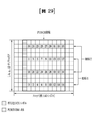
図3は、本発明の実施例で利用可能な下りリンクスロットに対するリソースグリッド(resource grid)を例示する図である。 FIG. 3 is a diagram illustrating a resource grid for downlink slots that can be used in the embodiments of the present invention.
図3を参照すると、1つの下りリンクスロットは時間領域において複数のOFDMシンボルを含む。ここで、1つの下りリンクスロットは7個のOFDMシンボルを含み、1つのリソースブロックは周波数領域において12個の副搬送波を含むとしているが、これに限定されるものではない。 Referring to FIG. 3, one downlink slot contains a plurality of OFDM symbols in the time domain. Here, it is assumed that one downlink slot contains 7 OFDM symbols and one resource block contains 12 subcarriers in the frequency domain, but the present invention is not limited to this.
リソースグリッド上で各要素(element)をリソース要素(resource element)といい、1つのリソースブロックは12×7個のリソース要素を含む。下りリンクスロットに含まれるリソースブロックの数NDLは、下りリンク送信帯域幅(bandwidth)に従属する。上りリンクスロットの構造は下りリンクスロットの構造と同一であってよい。 Each element on the resource grid is called a resource element, and one resource block contains 12 × 7 resource elements. The number of resource blocks contained in the downlink slot NDL depends on the downlink transmit bandwidth (bandwidth). The structure of the uplink slot may be the same as the structure of the downlink slot.
図4には、本発明の実施例で利用可能な上りリンクサブフレームの構造を示す。 FIG. 4 shows the structure of the uplink subframe that can be used in the embodiments of the present invention.
図4を参照すると、上りリンクサブフレームは、周波数領域において制御領域とデータ領域とに分けることができる。制御領域には、上りリンク制御情報を搬送するPUCCHが割り当てられる。データ領域には、ユーザデータを搬送するPUSCHが割り当てられる。単一搬送波特性を維持するために1つの端末はPUCCHとPUSCHを同時に送信しない。1つの端末に対するPUCCHにはサブフレーム内にRB対が割り当てられる。RB対に属するRBは2個のスロットのそれぞれにおいて異なる副搬送波を占める。このようなPUCCHに割り当てられたRB対は、スロット境界(slot boundary)で周波数ホッピング(frequency hopping)する、という。 With reference to FIG. 4, the uplink subframe can be divided into a control region and a data domain in the frequency domain. A PUCCH that carries uplink control information is assigned to the control area. A PUSCH that carries user data is assigned to the data area. One terminal does not transmit PUCCH and PUSCH at the same time in order to maintain the single carrier characteristic. An RB pair is assigned to the PUCCH for one terminal in a subframe. The RBs belonging to the RB pair occupy different subcarriers in each of the two slots. The RB pair assigned to such a PUCCH is said to be frequency hopping at the slot boundary.
図5は、本発明の実施例で利用可能な下りリンクサブフレームの構造を示す図である。 FIG. 5 is a diagram showing a structure of a downlink subframe that can be used in an embodiment of the present invention.
図5を参照すると、サブフレームにおける一番目のスロットにおいてOFDMシンボルインデックス0から最大で3個までのOFDMシンボルが、制御チャネルが割り当てられる制御領域(control region)であり、残りのOFDMシンボルは、PDSCHが割り当てられるデータ領域(data region)である。3GPP LTEで用いられる下りリンク制御チャネルの例に、PCFICH(Physical Control Format Indicator Channel)、PDCCH、PHICH(Physical Hybrid−ARQ Indicator Channel)などがある。
Referring to FIG. 5, in the first slot in the subframe, the
PCFICHはサブフレームの一番目のOFDMシンボルで送信され、サブフレームにおいて制御チャネルの送信のために用いられるOFDMシンボルの数(すなわち、制御領域のサイズ)に関する情報を搬送する。PHICHは、上りリンクに対する応答チャネルであり、HARQ(Hybrid Automatic Repeat Request)に対するACK(Acknowledgement)/NACK(Negative−Acknowledgement)信号を搬送する。PDCCHで送信される制御情報を下りリンク制御情報(DCI:downlink control information)という。下りリンク制御情報は、上りリンクリソース割り当て情報、下りリンクリソース割り当て情報、又は任意の端末グループに対する上りリンク送信(Tx)電力制御命令を含む。 PCFICH is transmitted in the first OFDM symbol of the subframe and carries information about the number of OFDM symbols used for transmission of the control channel in the subframe (ie, the size of the control area). The PHICH is a response channel for an uplink and carries an ACK (Acknowledgedgenment) / NACK (Negative-Acknowledgement) signal for a HARQ (Hybrid Automatic Repeat Request). The control information transmitted by PDCCH is called downlink control information (DCI: downlink control information). The downlink control information includes uplink resource allocation information, downlink resource allocation information, or uplink transmission (Tx) power control instructions for any terminal group.
1.3.CSIフィードバック 1.3. CSI feedback
3GPP LTE又はLTE−Aシステムでは、ユーザ機器(UE)がチャネル状態情報(CSI)を基地局(BS又はeNB)に報告するように定義されている。ここで、チャネル状態情報(CSI)は、UEとアンテナポートとの間に形成される無線チャネル(又は、リンク)の品質を示す情報を総称する。 In a 3GPP LTE or LTE-A system, the user equipment (UE) is defined to report channel state information (CSI) to the base station (BS or eNB). Here, channel state information (CSI) is a general term for information indicating the quality of a radio channel (or link) formed between a UE and an antenna port.
例えば、チャネル状態情報(CSI)は、ランク指示子(rank indicator,RI)、プリコーディング行列指示子(precoding matrix indicator,PMI)、チャネル品質指示子(channel quality indicator,CQI)などを含む。 For example, channel state information (CSI) includes rank indicator (RI), precoding matrix indicator (PMI), channel quality indicator (CQI), and the like.
ここで、RIは当該チャネルのランク(rank)情報を示し、これはUEが同一の時間−周波数リソースを介して受信するストリーム数を意味する。この値は、チャネルの長期フェーディング(Long Term Fading)により従属されて決定される。次いで、通常、RIはPMI、CQIより長い周期でUEによってBSにフィードバックされる。 Here, RI indicates the rank information of the channel, which means the number of streams received by the UE over the same time-frequency resource. This value is dependent on long-term fading of the channel (Long Term Fading). Next, the RI is usually fed back to the BS by the UE at a cycle longer than that of the PMI and CQI.
PMIはチャネル空間特性を反映した値であって、SINRなどのメトリック(metric)を基準としてUEが好むプリコーディングインデックスを示す。 The PMI is a value that reflects the channel spatial characteristics, and indicates a precoding index preferred by the UE based on a metric such as SINR.
CQIはチャネルの強度を示す値であって、通常、BSがPMIを用いた時に得られる受信SINRを意味する。 CQI is a value indicating the intensity of the channel, and usually means the received SINR obtained when BS uses PMI.
3GPP LTE又はLTE−Aシステムにおいて、基地局は複数のCSIプロセスをUEに設定し、UEから各プロセスに対するCSIの報告を受ける。ここで、CSIプロセスは、基地局からの信号品質の特定のためのCSI−RSと干渉測定のためのCSI干渉測定(CSI−interference measurement,CSI−IM)リソースで構成される。 In a 3GPP LTE or LTE-A system, the base station configures multiple CSI processes in the UE and receives reports of CSI for each process from the UE. Here, the CSI process is composed of CSI-RS for identifying the signal quality from the base station and CSI interference measurement (CSI-IM) resources for interference measurement.
1.4.RRM測定 1.4. RRM measurement
LTEシステムでは、電力制御(Power control)、スケジューリング(Scheduling)、セル検索(Cell search)、セル再選択(Cell reselection)、ハンドオーバー(Handover)、ラジオリンク又は連結モニタリング(Radio link or Connection monitoring)、連結確立/再確立(Connection establish/re−establish)などを含むRRM(Radio Resource Management)動作を支援する。この時、サービングセルは端末にRRM動作を行うための測定値であるRRM測定(measurement)情報を要求することができる。代表的な情報として、LTEシステムにおいて端末は各セルに対するセル検索(Cell search)情報、RSRP(reference signal received power)、RSRQ(reference signal received quality)などの情報を測定して報告することができる。具体的には、LTEシステムにおいて端末はサービングセルからRRM測定のための上位層信号として「measConfig」が伝達され、端末はこの「measConfig」の情報に従ってRSRP又はRSRQを測定する。 In LTE systems, power control, scheduling, cell search, cell selection, handover, radio link or connection monitoring, radio link or connection monitoring, It supports RRM (Radio Resource Management) operations including connection establishment / re-station and the like. At this time, the serving cell can request the terminal for RRM measurement information, which is a measured value for performing the RRM operation. As typical information, in the LTE system, the terminal can measure and report information such as cell search information for each cell, RSRP (reference siginal received power), and RSRQ (reference siginal received quality). Specifically, in the LTE system, the terminal transmits "mesConfig" as an upper layer signal for RRM measurement from the serving cell, and the terminal measures RSRP or RSRQ according to the information of this "mesConfig".
ここで、LTEシステムにおいて定義するRSRP、RSRQ、RSSIは、以下のように定義される。 Here, RSRP, RSRQ, and RSSI defined in the LTE system are defined as follows.
先ず、RSRPは考慮される測定周波数帯域内のセル特定の参照信号を送信するリソース要素の電力分布(power contribution、[W]単位)の線形平均で定義される。(Reference signal received power (RSRP), is defined as the linear average over the power contributions (in [W]) of the resource elements that carry cell−specific reference signals within the considered measurement frequency bandwidth.)一例として、RSRP決定のためにセル特定の参照信号R0が活用できる。(For RSRP determination the cell−specific reference signals R0 shall be used.)仮に、UEがセル特定の参照信号R1が利用可能であると検出する場合、UEはR1をさらに用いてRSRPを決定する。(If the UE can reliably detect that R1 is available it may use R1 in addition to R0 to determine RSRP.) First, RSRP is defined as a linear average of the power distribution (in [W] units) of the resource element that transmits the cell-specific reference signal within the measurement frequency band considered. (Reference signal received power (RSRP), is defined as the linear average over the power contributions (in [W]) of the resource elements that carry cell-specific reference signals within the considered measurement frequency bandwidth.) As an example, the RSRP decision Therefore, the cell-specific reference signal R0 can be utilized. (For RSRP determination the cell-specific reference signals R0 shall be used.) If the UE detects that a cell-specific reference signal R1 is available, the UE further uses R1 to determine the RSRP. (If the UE can reliable detect that R1 is available it may use R1 in addition to R0 to data RSRP.)
RSRPのための参照ポイントは、UEのアンテナコネクターとなり得る。(The reference point for the RSRP shall be the antenna connector of the UE.) The reference point for RSRP can be the antenna connector of the UE. (The reference point for the RSRP shall be the antenna connector of the UE.)
仮に、UEが受信器ダイバーシティを用いる場合、報告される値は個別のダイバーシティブランチに対応するRSRPより小さくてはならない。(If receiver diversity is in use by the UE, the reported value shall not be lower than the corresponding RSRP of any of the individual diversity branches.) If the UE uses receiver diversity, the reported value must not be less than the RSRP corresponding to the individual diversity branch. (If recipient individual is in use by the UE, the reported value shoulder not be lower the correspending RSRP of individual for the individual)
次いで、NがE−UTRA搬送波RSSI測定帯域幅のRBの数であるとき、RSRQはE−UTRA搬送波RSSIに対するRSRPの比率として、N*RSRP/(E−UTRA carrier RSSI)と定義される。(Reference Signal Received Quality (RSRQ) is defined as the ratio NかけるRSRP/(E−UTRA carrier RSSI), where N is the number of RB’s of the E−UTRA carrier RSSi measurement bandwidth.)この測定値の分母及び分子は、リソースブロックの同一のセットによって決定される。(The measurements in the numerator and denominator shall be made over the same set of resource blocks.) Then, when N is the number of RBs in the E-UTRA carrier RSSI measurement bandwidth, RSRQ is defined as N * RSRP / (E-UTRA carrier RSSI) as the ratio of RSRP to the E-UTRA carrier RSSI. (Reference Signal Received Quality (RSRQ) is defined as the ratio N times RSRP / (E-UTRA carrier RSSI), where New N is the number Ratio RB's And the molecule is determined by the same set of resource blocks. (The measurement in the numerator and denominator shall be made over the same set of resources blocks.)
E−UTRA搬送波RSSIは共同チャネル(co−channel)サービング及び非サービングセル、隣接チャネルの干渉、熱雑音などを含む全てのソースからの受信信号に対して、N個のリソースブロックにわたって、測定帯域幅でアンテナポート0に対する参照シンボルを含むOFDMシンボルのみで端末によって測定された受信全電力([W]単位)の線形平均を含む。(E−UTRA Carrier Received Signal Strength Indicator (RSSI), comprises the linear average of the total received power (in [W]) observed only in OFDM symbols containing reference symbols for antenna port 0, in the measurement bandwidth, over N number of resource blocks by the UE from all sources, including co−channel SERVING and non−SERVING cells, adjacent channel interference, thermal noise etc.)仮に、上位層シグナリングがRSRQ測定のためにあるサブフレームを指示した場合、指示されたサブフレームにおける全てのOFDMシンボルに対してRSSIが測定される。(If higher−layer signalling indicates certain subframes for performing RSRQ measurements, then RSSI is measured over all OFDM symbols in the indicated subframes.)
The E-UTRA carrier RSSI covers N resource blocks with measured bandwidth for received signals from all sources, including co-channel serving and non-serving cells, adjacent channel interference, thermal noise, etc. Includes a linear average of the total received power (in [W] units) measured by the terminal with only OFDM symbols containing a reference symbol for
RSRQのための参照ポイントは、UEのアンテナコネクターになり得る。(The reference point for the RSRQ shall be the antenna connector of the UE.) The reference point for RSRQ can be the antenna connector of the UE. (The reference point for the RSRQ shoulder be the antenna connector of the UE.)
仮に、UEが受信機ダイバーシティを用いる場合、報告される値は個別のダイバーシティブランチに対応するRSRQより小さくてはならない。(If receiver diversity is in use by the UE, the reported value shall not be lower than the corresponding RSRQ of any of the individual diversity branches.) If the UE uses receiver diversity, the reported value must not be less than the RSRQ corresponding to the individual diversity branch. (If recipient individual is in use by the UE, the reported value shoulder not be lower the correspending RSRQ of each individual)
次いで、RSSIは受信器パルス状のフィルターによって定義された帯域幅内の熱雑音及び受信器から生成された雑音を含む受信された広帯域電力で定義される。(Received Signal Strength Indicator (RSSI) is defined as the received wide band power, including thermal noise and noise generated in the receiver, within the bandwidth defined by the receiver pulse shaping filter.) RSSI is then defined by the received broadband power, including thermal noise within the bandwidth defined by the receiver pulsed filter and noise generated from the receiver. (Received Signal Strength Indicator (RSSI) is defined as the received wide band power, including thermal noise and noise generated in the receiver, within the bandwidth defined by the receiver pulse shaping filter.)
測定のための参照ポイントは、UEのアンテナコネクターになり得る。(The reference point for the measurement shall be the antenna connector of the UE.) The reference point for measurement can be the antenna connector of the UE. (The reference point for the measurement shall be the antenna connector of the UE.)
仮に、UEが受信器ダイバーシティを用いる場合、報告される値は個別のダイバーシティブランチに対応するUTRA搬送波RSSIより小さくてはならない。(If receiver diversity is in use by the UE, the reported value shall not be lower than the corresponding UTRA carrier RSSI of any of the individual receive antenna branches.) If the UE uses receiver diversity, the reported value must not be less than the UTRA carrier RSSI corresponding to the individual diversity branch. (If receiver individual is in use the UE, the reported value hall not be lower the color the coloning UTRA carrier antenna antenna)
上記の定義に従って、LTEシステムにおいて動作する端末は、周波数間の測定(Intra−frequency measurement)の場合、SIB3(system information block type 3)から送信される許容された測定帯域幅(Allowed measurement bandwidth)関連のIE(information element)を介して指示される帯域幅でRSRPを測定することができる。また、周波数内の測定(Inter−frequency measurement)である場合、端末はSIB5から送信される許容された測定帯域幅を介して指示された6、15、25、50、75、100RB(resource block)のうち1つに対応する帯域幅でRSRPを測定することができる。また、上述したようなIEがない場合、端末はデフォルト動作として全体DL(downlink)システムの周波数帯域でRSRPを測定することができる。 According to the above definition, the terminal operating in the LTE system is an allowed measurement bandwidth (Allowed measurement related band) transmitted from SIB3 (system information block type 3) in the case of frequency measurement (Intra-frequency measurement). RSRP can be measured with the bandwidth indicated via the IE (information frequency) of. Also, in the case of in-frequency measurement (Inter-frequency measurement), the terminal is indicated via the allowed measurement bandwidth transmitted from SIB5 at 6, 15, 25, 50, 75, 100 RB (resource block). RSRP can be measured with the bandwidth corresponding to one of them. Further, in the absence of IE as described above, the terminal can measure RSRP in the frequency band of the entire DL (downlink) system as a default operation.
この時、端末が許容された測定帯域幅に対する情報を受信する場合、端末は当該値を最大の測定帯域幅(maximum measurement bandwidth)として当該値においてRSRPの値を自由に測定することができる。但し、サービングセルがWB−RSRQと定義されるIEを端末に送信して、許容された測定帯域幅を50RB以上に設定する場合、端末は許容された測定帯域幅に対するRSRP値を全て算出する必要がある。一方、端末はRSSIを測定するとき、RSSI帯域幅の定義に従って端末の受信機が有する周波数帯域を用いてRSSIを測定する。 At this time, when the terminal receives the information for the allowable measurement bandwidth, the terminal can freely measure the RSRP value at the value with the value as the maximum measurement bandwidth (maximum measurement bandwidth). However, if the serving cell sends an IE defined as WB-RSRQ to the terminal and sets the permissible measurement bandwidth to 50 RB or more, the terminal must calculate all RSRP values for the permissible measurement bandwidth. be. On the other hand, when measuring RSSI, the terminal measures RSSI using the frequency band of the receiver of the terminal according to the definition of RSSI bandwidth.
2.新しい無線接続技術(New Radio Access Technology)システム2. New Radio Access Technology System
多数の通信機器がより大きな通信容量を要求することにより、既存の無線接続技術(radio access technology、RAT)に比べて向上した端末広帯域(Mobile Broadband)通信の必要性が高まっている。また多数の機器及び物事を連結していつでもどこでも多様なサービスを提供する大規模(massive)MTC(Machine Type Communications)も必要となっている。さらに信頼性及び遅延などに敏感なサービス/UEを考慮した通信システムのデザインが提示されている。 As a large number of communication devices demand a larger communication capacity, there is an increasing need for terminal broadband communication that is improved as compared with existing radio connection technology (Radio access technology, RAT). There is also a need for large-scale MTCs (Machine Type Communications) that connect a large number of devices and things to provide various services anytime, anywhere. Further, a communication system design considering services / UEs that are sensitive to reliability and delay is presented.
このように向上した端末広帯域通信(Enhanced mobile broadband communication)、大規模MTC、URLLC(Ultra−Relialbe and Low Latency Communication)などを考慮した新しい無線接続技術であって、新しい無線接続技術システムが提案されている。以下、本発明では便宜上、該当技術をNew RAT又はNR(New Radio)と称する。 A new wireless connection technology system has been proposed, which is a new wireless connection technology considering such improved terminal broadband communication (Enhanced mobile broadband communication), large-scale MTC, URLLC (Ultra-Realbe and Low Latency Communication), and the like. There is. Hereinafter, in the present invention, for convenience, the relevant technology will be referred to as New RAT or NR (New Radio).
2.1.ニューマロロジー(Numeriologies) 2.1. Numericologies
本発明が適用可能なNRシステムにおいては、以下の表のような様々なOFDMニューマロロジーが支援されている。この時、搬送波帯域幅部分(carrier bandwidth part)ごとのμ及び循環前置(サイクリックプレフィックス、cyclic prefix)情報は、下りリンク(DL)又は上りリンク(UL)ごとに各々シグナリングされる。一例として、下りリンク搬送波帯域幅部分(downlink carrier bandwidth part)のためのμ及び循環前置(cyclic prefix)情報は、上位層シグナリングDL−BWP−mu及びDL−MWP−cpを通じてシグナリングされる。他の例として、上りリンク搬送波帯域幅部分(uplink carrier bandwidth part)のためのμ及び循環前置(cyclic prefix)情報は、上位層シグナリングUL−BWP−mu及びUL−MWP−cpを通じてシグナリングされる。 In the NR system to which the present invention is applicable, various OFDM pneumatics as shown in the table below are supported. At this time, μ and cyclic prefix information for each carrier bandwidth portion are signaled for each downlink (DL) or uplink (UL), respectively. As an example, the μ and cyclic prefix information for the downlink carrier bandwidth portion is signaled through the upper layer signaling DL-BWP-mu and DL-MWP-cp. As another example, the μ and cyclic prefix information for the uplink carrier bandwise part is signaled through the upper layer signaling UL-BWP-mu and UL-MWP-cp. ..
2.2.フレーム構造 2.2. Frame structure
下りリンク及び上りリンクの伝送は10msの長さのフレームで構成される。フレームは1msの長さの10個のサブフレームで構成される。この時、各々のサブフレームごとに連続するOFDMのシンボルの数は
![]()
![]()
各々のフレームは2つの同じサイズのハーフフレーム(half−frame)で構成される。この時、各々のハーフフレームはサブフレーム0−4及びサブフレーム5−9で構成される。 Each frame consists of two half-frames of the same size (half-frame). At this time, each half frame is composed of subframes 0-4 and 5-9.
副搬送波間隔(subcarrier spacing)μに対して、スロットは1つのサブフレーム内において昇順に
![]()
![]()
![]()
![]()
![]()
![]()
![]()
![]()
![]()
![]()
本発明が適用可能なNRシステムにおいては、上記のようなスロット構造であって、セルフスロット構造(Self−Contained subframe structure)が適用されている。 In the NR system to which the present invention can be applied, a self-slot structure (Self-Contined subframe structure) is applied in the slot structure as described above.
図6は本発明に適用可能なセルフサブフレーム構造(Self−Contained subframe structure)を示す図である。 FIG. 6 is a diagram showing a self-subframe structure (Self-Contined subframe structure) applicable to the present invention.
図6において、斜線領域(例えば、symbol index=0)は下りリンク制御(downlink control)領域を示し、黒色領域(例えば、symbol index=13)は上りリンク制御(uplink control)領域を示す。その他の領域(例えば、symbol index=1〜12)は下りリンクデータ伝送又は上りリンクデータ伝送のために使用される。 In FIG. 6, a shaded area (for example, symbol index = 0) indicates a downlink control (downlink control) region, and a black region (for example, symbol index = 13) indicates an uplink control (uplink control) region. Other areas (eg, symbol indexes = 1-12) are used for downlink data transmission or uplink data transmission.
このような構造により基地局及びUEは1つのスロット内でDL伝送とUL伝送を順次に行うことができ、1つのスロット内でDLデータを送受信し、これに対するUL ACK/NACKも送受信することができる。結果として、この構造ではデータ伝送エラーの発生時にデータの再伝送までにかかる時間を短縮させることにより、最終データ伝達の遅延を最小化することができる。 With such a structure, the base station and the UE can sequentially perform DL transmission and UL transmission in one slot, and can transmit and receive DL data in one slot, and also transmit and receive UL ACK / NACK for this. can. As a result, this structure can minimize the delay in final data transmission by reducing the time it takes to retransmit data when a data transmission error occurs.
このようなセルフスロット構造においては、基地局とUEが送信モードから受信モードに、又は受信モードから送信モードに転換するために一定の時間長さのタイムギャップ(time gap)が必要である。このために、セルフスロット構造においてDLからULに転換される時点の一部のOFDMシンボルは、ガード区間(guard period、GP)として設定されることができる。 In such a self-slot structure, a time gap (time gap) of a certain time length is required for the base station and the UE to switch from the transmission mode to the reception mode or from the reception mode to the transmission mode. For this reason, some OFDM symbols at the time of conversion from DL to UL in the self-slot structure can be set as a guard period (GP).
以上ではセルフスロット構造がDL制御領域及びUL制御領域を全て含む場合を説明したが、制御領域はセルフスロット構造に選択的に含まれることができる。即ち、本発明によるセルフスロット構造は、図6に示したように、DL制御領域及びUL制御領域を全て含む場合だけではなく、DL制御領域又はUL制御領域のみを含む場合もある。 Although the case where the self-slot structure includes all the DL control area and the UL control area has been described above, the control area can be selectively included in the self-slot structure. That is, as shown in FIG. 6, the self-slot structure according to the present invention may include not only the DL control area and the UL control area but also only the DL control area or the UL control area.
一例として、スロットは様々なスロットフォーマットを有することができる。この時、各々のスロットのOFDMシンボルは下りリンク(‘D’と表す)、フレキシブル(‘X’と表す)及び上りリンク(‘U’と表す)に分類される。 As an example, slots can have various slot formats. At this time, the OFDM symbols of each slot are classified into downlink (represented as'D'), flexible (represented as'X'), and uplink (represented as'U').
従って、下りリンクスロットにおいてUEは下りリンク伝送が‘D’及び‘X’シンボルでのみ発生すると仮定できる。同様に、上りリンクスロットにおいてUEは上りリンク伝送が‘U’及び‘X’シンボルでのみ発生すると仮定できる。 Therefore, in the downlink slot, the UE can assume that downlink transmission occurs only with the'D'and'X' symbols. Similarly, in the uplink slot, the UE can assume that uplink transmission occurs only on the'U'and'X' symbols.
2.3.アナログビーム形成(アナログビームフォーミング、Analog Beamforming) 2.3. Analog beam forming (Analog Beamforming)
ミリ波(Millimeter Wave、mmW)では波長が短いので、同一面積に多数のアンテナ要素(element)の設置が可能である。即ち、30GHz帯域において波長は1cmであるので、5*5cmのパネルに0.5lambda(波長)間隔で2次元(2−dimension)配列する場合、合計100個のアンテナ要素を設けることができる。これにより、ミリ波(mmW)では多数のアンテナ要素を使用してビーム形成(beamforming、BF)利得を上げてカバレッジを増加させる、或いはスループット(throughput)を向上させることができる。 Since the wavelength of millimeter wave (millimeter wave, mmW) is short, it is possible to install a large number of antenna elements in the same area. That is, since the wavelength is 1 cm in the 30 GHz band, a total of 100 antenna elements can be provided when two-dimensional (2-dimension) arrangement is performed at 0.5 lambda (wavelength) intervals on a 5 * 5 cm panel. This makes it possible to use a large number of antenna elements in millimeter waves (mmW) to increase beamforming (BF) gain to increase coverage or improve throughput.
この時、アンテナ要素ごとに伝送パワー及び位相の調節ができるように、各々のアンテナ要素はTXRU(transceiver)を含む。これにより、各々のアンテナ要素は周波数リソースごとに独立的なビーム形成を行うことができる。 At this time, each antenna element includes a TXRU (transceiver) so that the transmission power and the phase can be adjusted for each antenna element. This allows each antenna element to form an independent beam for each frequency resource.
しかし、100個以上の全てのアンテナ要素にTXRUを設けることは費用面で実効性が乏しい。従って、1つのTXRUに多数のアンテナ要素をマッピングし、アナログ位相シフター(analog phase shifter)でビーム方向を調節する方式が考えられている。かかるアナログビーム形成方式では全帯域において1つのビーム方向のみを形成できるので、周波数選択的なビーム形成が難しいという短所がある。 However, it is not cost effective to provide TXRU for all 100 or more antenna elements. Therefore, a method is considered in which a large number of antenna elements are mapped to one TXRU and the beam direction is adjusted by an analog phase shifter. In such an analog beam forming method, since only one beam direction can be formed in the entire band, there is a disadvantage that frequency-selective beam forming is difficult.
これを解決するために、デジタルビーム形成及びアナログビーム形成の中間形態として、Q個のアンテナ要素より少ない数のB個のTXRUを有するハイブリッドビーム形成(hybrid BF)が考えられる。この場合、B個のTXRUとQ個のアンテナ要素の連結方式によって差はあるが、同時に伝送可能なビームの方向はB個以下に制限される。 In order to solve this, as an intermediate form between digital beam formation and analog beam formation, hybrid beam formation (hybrid BF) having B TXRUs having a smaller number than Q antenna elements can be considered. In this case, the direction of the beams that can be transmitted at the same time is limited to B or less, although there is a difference depending on the connection method of the B TXRU and the Q antenna elements.
図7及び図8は、TXRUとアンテナ要素(element)の代表的な連結方式を示す図である。ここで、TXRU仮想化(virtualization)モデルは、TXRUの出力信号とアンテナ要素の出力信号との関係を示す。 7 and 8 are diagrams showing a typical connection method between the TXRU and the antenna element (element). Here, the TXRU virtualization model shows the relationship between the output signal of the TXRU and the output signal of the antenna element.
図7はTXRUがサブアレイ(sub−array)に連結された方式を示している。図7の場合、アンテナ要素は1つのTXRUのみに連結される。 FIG. 7 shows a method in which TXRU is connected to a sub array (sub-array). In the case of FIG. 7, the antenna element is connected to only one TXRU.
反面、図8はTXRUが全てのアンテナ要素に連結された方式を示している。図8の場合、アンテナ要素は全てのTXRUに連結される。この時、アンテナ要素が全てのTXRUに連結されるためには、図8に示したように、別の加算器が必要である。 On the other hand, FIG. 8 shows a method in which TXRU is connected to all antenna elements. In the case of FIG. 8, the antenna element is connected to all TXRUs. At this time, in order for the antenna element to be connected to all TXRUs, another adder is required as shown in FIG.
図7及び図8において、Wはアナログ位相シフター(analog phase shifter)により乗じられる位相ベクトルを示す。即ち、Wはアナログビーム形成の方向を決定する主要パラメータである。ここで、CSI−RSアンテナポートと複数のTXRUとのマッピングは1:1又は1:多である。 In FIGS. 7 and 8, W represents a phase vector multiplied by an analog phase shifter. That is, W is a main parameter that determines the direction of analog beam formation. Here, the mapping between the CSI-RS antenna port and the plurality of TXRUs is 1: 1 or 1: many.
図7の構成によれば、ビーム形成のフォーカシングが難しいという短所があるが、全てのアンテナ構成を低価で構成できるという長所がある。 According to the configuration of FIG. 7, there is a disadvantage that focusing of beam formation is difficult, but there is an advantage that all antenna configurations can be configured at a low cost.
図8の構成によれば、ビーム形成のフォーカシングが容易であるという長所がある。但し、全てのアンテナ要素にTXRUが連結されるので、全体の費用が増加するという短所がある。 According to the configuration of FIG. 8, there is an advantage that focusing of beam formation is easy. However, since the TXRU is connected to all the antenna elements, there is a disadvantage that the overall cost increases.
本発明が適用可能なNRシステムにおいて、複数のアンテナが使用される場合、デジタルビーム形成(Digital beamforming)及びアナログビーム形成を結合したハイブリッドビーム形成(hybrid beamforming)方式が適用される。この時、アナログビーム形成(又はRF(radio frequency)ビーム形成)は、RF端でプリコーディング(又は組み合わせ(combining))を行う動作を意味する。またハイブリッドビーム形成において、ベースバンド(baseband)端とRF端は各々プリコーティング(又は組み合わせ)を行う。これによりRFチェーンの数とD/A(Digital to analog)(又はA/D(analog to digital))コンバーターの数を減らしながらデジタルビーム形成に近接する性能を得られるという長所がある。 When a plurality of antennas are used in the NR system to which the present invention is applicable, a hybrid beamforming method that combines digital beamforming and analog beamforming is applied. At this time, analog beam formation (or RF (radio frequency) beam formation) means an operation of performing precoding (or combining) at the RF end. Further, in hybrid beam formation, the baseband end and the RF end are each precoated (or combined). This has the advantage that performance close to digital beam formation can be obtained while reducing the number of RF chains and the number of D / A (Digital to analog) (or A / D (analog to digital)) converters.
説明の便宜上、ハイブリッドビーム形成の構造は、N個の送受信端(transceiver unit、TXRU)とM個の物理的アンテナで表すことができる。この時、送信端から伝送するL個のデータ層(digital layer)に対するデジタルビーム形成は、N*L(L by L)行列で表される。その後、変換されたN個のデジタル信号はTXRUを介してアナログ信号に変換され、変換された信号に対してM*N(M by N)行列で表されるアナログビーム形成が適用される。 For convenience of explanation, the structure of the hybrid beam formation can be represented by N transceiver units (TXRU) and M physical antennas. At this time, the digital beam formation for the L data layers (digital layerers) transmitted from the transmission end is represented by an N * L (L by L) matrix. After that, the converted N digital signals are converted into analog signals via TXRU, and analog beam formation represented by an M * N (M by N) matrix is applied to the converted signals.
図9は、本発明の一例によるTXRU及び物理的アンテナ観点におけるハイブリッドビーム形成の構造を簡単に示す図である。この時、図9においてデジタルビームの数はL個であり、アナログビームの数はN個である。 FIG. 9 is a diagram briefly showing the structure of hybrid beam formation from the viewpoint of TXRU and a physical antenna according to an example of the present invention. At this time, in FIG. 9, the number of digital beams is L, and the number of analog beams is N.
さらに、本発明が適用可能なNRシステムにおいては、基地局がアナログビーム形成をシンボル単位で変更できるように設計して、所定の地域に位置した端末に効率的なビーム形成を支援する方法が考えられる。さらに、図9に示したように、所定のN個のTXRUとM個のRFアンテナを1つのアンテナパネルに定義した時、本発明によるNRシステムにおいては、互いに独立したハイブリッドビーム形成が適用可能な複数のアンテナパネルを導入する方法も考えられる。 Further, in the NR system to which the present invention can be applied, a method of designing the base station so that the analog beam formation can be changed on a symbol-by-symbol basis to support efficient beam formation at a terminal located in a predetermined area is conceivable. Be done. Further, as shown in FIG. 9, when a predetermined N TXRU and M RF antennas are defined in one antenna panel, in the NR system according to the present invention, hybrid beam formation independent of each other can be applied. A method of introducing a plurality of antenna panels is also conceivable.
以上のように基地局が複数のアナログビームを活用する場合、端末ごとに信号の受信に有利なアナログビームが異なる。よって本発明が適用可能なNRシステムにおいては、基地局が所定のサブフレーム(SF)内でシンボルごとに異なるアナログビームを適用して(少なくとも同期信号、システム情報、ページング(paging)など)信号を伝送することにより、全ての端末が受信機会を得るようにするビーム掃引(ビームスウィーピング、beam sweeping)動作が考えられている。 As described above, when the base station utilizes a plurality of analog beams, the analog beams that are advantageous for receiving signals differ depending on the terminal. Therefore, in the NR system to which the present invention can be applied, the base station applies a different analog beam for each symbol within a predetermined subframe (SF) (at least synchronization signal, system information, paging, etc.) to transmit a signal. A beam sweeping operation is considered in which all terminals have a reception opportunity by transmitting the signal.
図10は本発明の一例による下りリンク(Downlink、DL)伝送過程において、同期信号(Synchronization signal)とシステム情報(System information)に対するビーム掃引(Beam sweeping)動作を簡単に示す図である。 FIG. 10 is a diagram briefly showing a beam sweeping operation with respect to a synchronization signal (Synchronization signal) and system information (System information) in a downlink (Downlink, DL) transmission process according to an example of the present invention.
図10において、本発明が適用可能なNRシステムのシステム情報がブロードキャスティング(Broadcasting)方式で伝送される物理的リソース(又は物理チャネル)を、xPBCH(physical broadcast channel)と称する。この時、1つのシンボル内で互いに異なるアンテナパネルに属する複数のアナログビームは同時に伝送可能である。 In FIG. 10, a physical resource (or physical channel) through which system information of an NR system to which the present invention is applicable is transmitted by a broadcast method is referred to as an xPBCH (physical broadcast channel). At this time, a plurality of analog beams belonging to different antenna panels within one symbol can be transmitted at the same time.
また図10に示したように、本発明が適用可能なNRシステムにおいて、アナログビームごとのチャネルを測定するための構成であって、(所定のアンテナパネルに対応する)単一のアナログビームが適用されて伝送される参照信号(Reference signal、RS)であるビーム参照信号(Beam RS、BRS)の導入が論議されている。BRSは複数のアンテナポットに対して定義され、BRSの各々のアンテナポットは単一のアナログビームに対応する。この時、BRSとは異なり、同期信号又はxPBCHは、任意の端末がよく受信するようにアナログビームのグループ内の全てのアナログビームが適用されて伝送される。 Further, as shown in FIG. 10, in the NR system to which the present invention can be applied, a configuration for measuring a channel for each analog beam, to which a single analog beam (corresponding to a predetermined antenna panel) is applied. The introduction of beam reference signals (Beam RS, BRS), which are reference signals (Reference signals, RS) transmitted by being transmitted, has been discussed. BRS is defined for multiple antenna pots, and each antenna pot of BRS corresponds to a single analog beam. At this time, unlike the BRS, the synchronization signal or xPBCH is transmitted by applying all the analog beams in the group of analog beams so that any terminal can receive them well.
3.提案する実施例3. 3. Proposed example
本発明では上記のような技術的思想に基づいて、基地局と端末で構成された無線通信システムにおいてUCI(uplink control information)をULデータ送信のための物理層チャネルであるPUSCH(physical uplink shared channel)リソース領域に送信する場合の、UCIマッピング方法について詳しく説明する。言い換えれば、本発明ではUEがUCIをPUSCHを介して送信する具体的な方法について詳しく説明する。 In the present invention, based on the above technical idea, PUSCH (physical uplink shared channel), which is a physical layer channel for transmitting UL data, uses UCI (uplink control information) in a wireless communication system composed of a base station and a terminal. ) The UCI mapping method when transmitting to the resource area will be described in detail. In other words, the present invention details a specific method by which the UE transmits the UCI via the PUSCH.
従来のLTEシステムでは、PAPR(Peak to Average Power Ratio)を減少させて端末がより高い送信電力でULデータ送信する構成を支援した。これにより、ULカバレッジを増大させることができる。よって、従来のLTEシステムでは、単一の搬送波特性(Single carrier property)を有するSC−FDMA(Single Carrier−Frequency Division Multiplexing Access)又はDFT−s−OFDM(Discrete Fourier Transform−spread−OFDM)基盤の送信方式が適用された。SC−FDMA方式は、OFDM方式によるIDFT(Inverse Discrete Fourier Transform)(又はIFFT(Inverse Fast Fourier Transform)過程前にDFTプリコーディング(又はDFTスプレディング)をデータに適用して送信する方式である。よって、端末が時間軸でM個のデータを生成した後、M個のポイントのDFTブロック(M−point DFT block)及びN個のポイントのIDFTブロック(N−point IDFT block)(但し、N≧M)の処理を経ると、端末の時間軸データはN/Mの比率でアップサンプリング(Upsampling)された時間軸信号に変換されて単一の搬送波特性を満たす。 In the conventional LTE system, PAPR (Peek to Average Power Radio) is reduced to support the configuration in which the terminal transmits UL data with higher transmission power. This makes it possible to increase UL coverage. Therefore, in a conventional LTE system, SC-FDMA (Single Carrier-Frequency Division Multiplexing Access) or DFT-s-OFDM (Discrete Fourier Transform) with a single carrier characteristic (Single carrier property) has a single carrier characteristic (Single carrier property). The method was applied. The SC-FDMA method is a method in which DFT precoding (or DFT spreading) is applied to data before the IDFT (Inverse Discrete Fourier Transform) (or IFFT (Inverse Fast Fourier Transform) process) by the OFDM method and transmitted. , After the terminal generates M data on the time axis, DFT block of M points (M-point DFT block) and IDFT block of N points (N-point IDFT block) (however, N ≧ M ), The time axis data of the terminal is converted into an upsampled time axis signal at an N / M ratio to satisfy a single carrier characteristic.
但し、本発明が適用可能なNRシステムでは、PUSCH送信波形によりSC−FDMAだけではなく、CP−OFDM(Cyclic Prefix−OFDM、即ち、OFDMの前でデータにDFTブロックを適用したOFDM方式)基盤のPUSCH送信も支援できる。この時、上記のようにCP−OFDM基盤のPUSCH送信が行われる場合、NRシステムは単一の搬送波特性の制約から比較的自由であるデータ及びRSリソースマッピングを支援できる。これにより、RSオーバーヘッドをチャネルにより最小化できるという長所がある。 However, in the NR system to which the present invention can be applied, not only SC-FDMA but also CP-OFDM (Cyclic Prefix-OFDM, that is, an OFDM method in which a DFT block is applied to data before OFDM) based on the PUSCH transmission waveform is used. PUSCH transmission can also be supported. At this time, when the CP-OFDM-based PUSCH transmission is performed as described above, the NR system can support data and RS resource mapping that are relatively free from the constraints of a single carrier characteristic. This has the advantage that RS overhead can be minimized by the channel.
よって、本発明に適用可能なNRシステムにおいては、端末はPUSCH送信方式として上記2つの方式を全て支援できる。具体的には、端末は基地局の設定によって短いULカバレッジでも十分である場合は、CP−OFDM基盤のPUSCH送信を行い、長いULカバレッジが求められる場合には、SC−OFDM基盤のPUSCH送信を行うことができる。 Therefore, in the NR system applicable to the present invention, the terminal can support all of the above two methods as the PUSCH transmission method. Specifically, the terminal performs CP-OFDM-based PUSCH transmission when a short UL coverage is sufficient depending on the base station settings, and performs SC-OFDM-based PUSCH transmission when long UL coverage is required. It can be carried out.
また、本発明が適用可能なNRシステムにおいて、URLLCNなどのサービスは超低遅延(Ultra−low Latency)の要求事項を有することができる。従って、場合によっては、既に送信されたeMBBデータがパンクチャリングされる形態でURLLCデータが送信されることができる。一例として、端末がeMBBサービスによるPUSCH1の送信指示を受け、その後PUSCH1送信対象スロットでURLLCサービスによるPUSCH2の送信指示を受ける場合、端末はスロット内の一部のPUSCH1データをパンクチャリングする形態でPUSCH2の送信を行うことができる。 Further, in the NR system to which the present invention can be applied, services such as URLLCN can have a requirement of ultra-low latency. Therefore, in some cases, the URLLC data can be transmitted in a form in which the already transmitted eMBB data is punctured. As an example, when the terminal receives a PUSCH1 transmission instruction by the eMBB service and then receives a PUSCH2 transmission instruction by the URLLC service in the PUSCH1 transmission target slot, the terminal punctures a part of the PUSCH1 data in the slot. Can send.
また本発明が適用可能なNRシステムでは、UCIがPUSCH領域を介して送信されるUCIピギーバックが適用されることができる。この時、PUSCH送信方式がCP−OFDM方式であるかSC−FDMA方式であるかによって、異なるPUSCH内のUCIマッピング方式が適用される。また、URLLCなどの他のサービスによるパンクチャリングを考慮して、異なるUCIマッピング方法が設計されることもできる。 Further, in the NR system to which the present invention is applicable, a UCI piggyback in which the UCI is transmitted via the PUSCH region can be applied. At this time, different UCI mapping methods in PUSCH are applied depending on whether the PUSCH transmission method is the CP-OFDM method or the SC-FDMA method. Also, different UCI mapping methods can be designed in consideration of puncturing by other services such as URLLC.
以下の説明において、DCI(Dynamic control information)は動的な制御信号を意味する。 In the following description, DCI (Dynamic control information) means a dynamic control signal.
また以下の説明において、RE(resource element)は時間リソースであるOFDMリソースと周波数リソースである副搬送波リソースのグリッド(grid)形態で表現できる。よって、REは特定の副搬送波及び特定のOFDMシンボルに対応するリソースを意味する。 Further, in the following description, RE (resure element) can be expressed in the form of a grid of an OFDM resource which is a time resource and a subcarrier resource which is a frequency resource. Thus, RE means a resource corresponding to a particular subcarrier and a particular OFDM symbol.
また以下の説明において、DM−RS(demodulation reference signal)はデータ復調を目的としてチャネル推定などの受信動作を支援する参照信号を意味する。 Further, in the following description, DM-RS (demodulation reference signal) means a reference signal that supports a reception operation such as channel estimation for the purpose of data demodulation.
また以下の説明において、スロットはデータスケジューリングのための基本時間単位を意味し、複数のシンボルで構成される。またミニスロットはデータスケジューリングのための最小時間単位であり、スロットよりも短い時間区間を有するように定義される。この時、シンボルはOFDMシンボル又はSC−FDMAシンボルを意味する。 Further, in the following description, a slot means a basic time unit for data scheduling and is composed of a plurality of symbols. A minislot is the minimum time unit for data scheduling and is defined to have a shorter time interval than the slot. At this time, the symbol means an OFDM symbol or an SC-FDMA symbol.
また以下の説明において、時間優先マッピング(Time−first mapping)(又は周波数優先マッピング(Frequency−first mapping))は、該当情報に対するREマッピングを行う時、まず特定の周波数リソース(又は時間リソース)について時間軸(又は周波数軸)方向にRE割り当てを行い、その後、他の周波数リソース(又は時間リソース)について再び時間軸(又は周波数軸)方向にRE割り当てを行う方式を意味する。 Further, in the following description, in the time priority mapping (Time-first mapping) (or frequency priority mapping (Frequency-first mapping)), when RE mapping is performed on the corresponding information, first, the time is obtained for a specific frequency resource (or time resource). It means a method in which RE allocation is performed in the axis (or frequency axis) direction, and then RE allocation is performed again in the time axis (or frequency axis) direction for other frequency resources (or time resources).
また本発明に関する図において、UCIが割り当てられるRE上の数字はUCIをREにマッピングする順序を意味する。 Further, in the figure relating to the present invention, the number on RE to which UCI is assigned means the order in which UCI is mapped to RE.
3.1.第1のUCI送信方法 3.1. First UCI transmission method
UEがPUSCHにUCIピギーバックを行う場合、UEはPUSCHに送信する符号化ビット(Coded bit)に対する変調前段階で符号化データビット(Coded data bit)と符号化UCIビット(Coded UCI bit)を結合した後、この結合された符号化ビット(Coded bit)を変調した信号をREにマッピングしてPUSCHに送信する。 When the UE performs UCI piggyback on the PUSCH, the UE combines the coded data bit (Coded data bit) and the coded UCI bit (Coded UCI bit) with respect to the coded bit (Coded bit) transmitted to the PUSCH. After that, the signal obtained by modulating the combined coded bit is mapped to RE and transmitted to PUSCH.
この時、PUSCHで送信可能な符号化ビットがNビットであり、符号化UCIビットがMビットである場合、UEは以下のうちのいずれかの方法により、符号化データビットと符号化UCIビットを結合することができる。 At this time, if the coded bit that can be transmitted by the PUSCH is N bit and the coded UCI bit is M bit, the UE uses one of the following methods to convert the coded data bit and the coded UCI bit. Can be combined.
(1)Nビットの長さに合わせて符号化データビットを生成し、その後、符号化データビットのうちの一部のMビットをパンクチャリングして該当位置に符号化UCIビットを挿入 (1) A coded data bit is generated according to the length of the N bit, and then some M bits of the coded data bit are punctured and the coded UCI bit is inserted at the corresponding position.
(2)(N−M)ビットの長さに合わせて符号化データビットを生成し、その後、符号化UCIビットを結合 (2) A coded data bit is generated according to the length of the (NM) bit, and then the coded UCI bit is combined.
ここで、符号化データビットに対してパンクチャリングされるMビット情報は、LSB(least significant bit)からMSB(most significant bit)方向への順次的なMビット情報である。 Here, the M-bit information that is punctured with respect to the encoded data bits is sequential M-bit information in the direction from the LSB (most significant bit) to the MSB (most significant bit).
また、変調次数(Modulation order)がKビットを支援する時、符号化UCIビットの長さがKの倍数で示されるビットサイズを有するように制限される。かかる動作により、データとUCIがRE単位で区分され、UCI送信REに対する追加電力の割り当てなどが適用される。 Also, when the modulation order supports K bits, the length of the encoded UCI bits is limited to having a bit size represented by a multiple of K. By such an operation, the data and the UCI are separated by the RE unit, and the allocation of additional power to the UCI transmission RE and the like are applied.
また、符号化データビットと符号化UCIビットの結合過程においてビットレベルのインターリービング(bit level interleaving)が適用され、その後、変調されたシンボルに対するREマッピング時に、さらにシンボルレベルのインターリービング(Symbol level interleaving)が適用される。 Further, bit level interleaving is applied in the process of combining the coded data bit and the coded UCI bit, and then symbol level interleaving (Symbol level interleaving) is further applied during RE mapping for the modulated symbol. ) Applies.
図11は本発明による第1のUCI送信方法を簡単に示す図である。 FIG. 11 is a diagram briefly showing the first UCI transmission method according to the present invention.
図11において、PUSCHで送信可能な符号化ビット(coded bit)がNビットであり、符号化UCIビットがMビットである場合を仮定する。この時、図11の左側に示した方法のように、UEは変調前段階(即ち、変調ブロックの前端)で符号化されたデータビットの一部のMビットをパンクチャリングし、符号化UCIビットと符号化データビットを結合した全体符号化ビットを変調した後、PUSCHで変調信号を送信することができる。又は図11の右側に示した方法のように、UEは符号化データビットの長さが(N−M)ビットになるようにレートマッチング(rate−matching)した後、符号化UCIビットを結合することができる。 In FIG. 11, it is assumed that the coded bit that can be transmitted by the PUSCH is N bits and the coded UCI bit is M bits. At this time, as shown on the left side of FIG. 11, the UE punctures some M bits of the data bits encoded in the pre-modulation stage (that is, the front end of the modulation block) and encodes the UCI bits. After modulating the entire coded bit, which is a combination of the coded data bit and the coded data bit, the modulated signal can be transmitted by PUSCH. Alternatively, as shown on the right side of FIG. 11, the UE rate-matches the coded data bits so that the length of the coded data bits is (NM) bits, and then combines the coded UCI bits. be able to.
このようにPUSCHへのREマッピング前にデータとUCIを混ぜる場合、符号化ビット(coded bit)のREマッピング過程でインターリービングされる効果がデータだけではなく、UCIにも同様に適用されることができる。よって、UCIの送信時、時間/周波数ダイバーシティ(Time/Frequency diversity)利得が得られるという長所がある。 When data and UCI are mixed before RE mapping to PUSCH in this way, the effect of interleaving in the RE mapping process of the coded bit can be applied not only to the data but also to UCI as well. can. Therefore, there is an advantage that a time / frequency diversity gain can be obtained at the time of UCI transmission.
さらに、データが複数のコードブロック(code block;CB)又はコードブロックグループ(code block group;CBG)で構成されて送信される場合、符号化UCIビットはCB又はCBGに分散されて送信されることができる。一例として、PUSCHで送信可能な符号化ビット(coded bit)がNビットであり、符号化UCIビットがMビットであり、CBG数がL個である場合、UEは以下のように符号化データビットと符号化UCIビットを結合することができる。 Further, when the data is composed of a plurality of code blocks (CB) or code block groups (CBG) and transmitted, the encoded UCI bits are distributed and transmitted to the CB or CBG. Can be done. As an example, when the coded bit that can be transmitted by PUSCH is N bit, the coded UCI bit is M bit, and the number of CBG is L, the UE has the coded data bit as follows. And the encoded UCI bits can be combined.
1)N1+N2+…+NL=Nビットを満たす{N1、N2、…、NL}とM1+M2+…+ML=Mビットを満たす{M1、M2、…、ML}を設定。その後、L個のCBGについてl番目の(例:l=1、2、…、L)CBGにN1ビットの符号化データビットを割り当てた後、上記符号化データビットのうちの一部のM1ビットをパンクチャリングし、該当位置に符号化UCIビットを挿入。 1) N 1 + N 2 + ... + N L = N bits are satisfied {N 1 , N 2 , ..., N L } and M 1 + M 2 + ... + M L = M bits are satisfied {M 1 , M 2 , ..., set the M L}. Then, for the L CBGs, the l-th (eg, l = 1, 2, ..., L) CBGs are assigned N 1- bit encoded data bits, and then some M of the above-mentioned encoded data bits are assigned. Puncture 1 bit and insert the coded UCI bit at the corresponding position.
2)N1+N2+…+NL=(N−M)ビットを満たす{N1、N2、…、NL}とM1+M2+…+ML=Mビットを満たす{M1、M2、…、ML}を設定。その後、L個のCBGについてl番目の(例:l=1、2、…、L)CBGにNlビットの符号化データビットを割り当てた後、Mlビットの符号化UCIビットをさらに結合。 2) N 1 + N 2 + ... + N L = (NM) bit satisfying {N 1 , N 2 , ..., N L } and M 1 + M 2 + ... + M L = M bit satisfying {M 1 , M 2, ..., set the M L}. Then, for the L CBGs, the l-th (eg, l = 1, 2, ..., L) CBGs are assigned N l- bit encoded data bits, and then the M l- bit encoded UCI bits are further combined.
以下の説明において、RE(resource element)は1つのOFDMシンボルの1つの副搬送波に対応するリソースを意味し、RB(resource block)又はPRB(physical resource block)は時間軸にM1(例:7又は14)個のシンボル及び周波数軸にM2(例:12)個の副搬送波で構成されたリソース割り当て単位を意味すると仮定する。 In the following description, RE (resource frequency) means a resource corresponding to one subcarrier of one OFDM symbol, and RB (resource block) or PRB (physical resource block) is M 1 (example: 7) on the time axis. Or 14) it is assumed to mean a resource allocation unit composed of M 2 (example: 12) subcarriers on the frequency axis.
本発明が適用可能なNRシステムにおいて、以下の一連の過程によるチャネルコーディング(Channel coding)チェーンが定義される。 In the NR system to which the present invention is applicable, a channel coding chain is defined by the following series of processes.
[Channel coding chain] [Cannel coding chain]
[1]TB(transport block)。TBS(transport block size)によるTB生成 [1] TB (transport block). TB generation by TBS (transport block size)
[2]TB CRC(Cyclic Redundancy Check)付着(attachment)。TBに対するCRC適用 [2] TB CRC (Cyclic Redundancy Check) adhesion (attackment). CRC application to TB
[3]CB(code block)分割(segmentation)。(TBが一定サイズ以上であると)TBを複数のCBに分割 [3] CB (code block) segmentation. Divide TB into multiple CBs (when TB is larger than a certain size)
[4]CB CRC付着。CBに対するCRC適用 [4] CB CRC adhesion. CRC application to CB
[5]チャネルコーディング(Channel coding)。各CBごとにチャネルコーディングを行う [5] Channel coding. Channel coding for each CB
ここで、チャネルコーディング方法によって符号化ビット(coded bit)が系統的な(Systematic)ビットグループ又はn番目のパリティビット(Parity bit)(例:n=1、2、3、…)グループに区分される時、各ビットグループ内のビットの間の順序を混ぜるサブブロックインターリーバ(Sub−block interleaver)が適用されることができる。その後、各ビットグループの間に追加インターリービングが適用されることもできる。 Here, the coded bit is divided into a systematic bit group or an nth parity bit (eg, n = 1, 2, 3, ...) Group according to the channel coding method. At that time, a subblock interleaver that mixes the order between the bits in each bit group can be applied. Additional interleaving can then be applied between each bit group.
[6]レートマッチング(Rate matching)。各CBごとの符号化ビットを特定の手順(例:系統的なビット−>パリティビット)によって(循環(Circular))バッファに入力し、(循環)バッファ内の特定の開始時点からデータ送信チャネルへ送信可能な(CBごとの)ビット量に対応する一例の符号化ビットを選択 [6] Rate matching. The coding bits for each CB are input into the (Circular) buffer by a specific procedure (eg, systematic bits-> parity bits), and from a specific start point in the (circular) buffer to the data transmission channel. Select an example coded bit that corresponds to the amount of bits that can be transmitted (per CB)
ここで、(循環)バッファ内の特定の開始時点はDLスケジューリングDCI又はDLスケジューリングDCI内のRV(redundancy version)により指示されることができる。 Here, the specific start time in the (circular) buffer can be indicated by the DL scheduling DCI or the RV (redundancy version) in the DL scheduling DCI.
また循環バッファであり、特定のCBについてL個のビットが選択される場合、index(k0)mod K、index(k0+1)mod K、…、index(k0+L)mod Kに対応するL個ビットが選択されることができる。ここで、index k0はDCI又はRVにより指示された時点を意味し、Kは循環バッファの全体サイズを意味する。 It is also a circular buffer, and when L bits are selected for a specific CB, it corresponds to index (k 0 ) mod K, index (k 0 + 1) mod K, ..., index (k 0 + L) mod K. L bits can be selected. Here, index k 0 means the time point indicated by DCI or RV, and K means the total size of the circulation buffer.
[7]CB連結(concatenation)。CBごとの符号化ビット(coded bit)を結合 [7] CB concatenation. Combine coded bits for each CB
[8]チャネルインターリービング(Channel interleaving)。データREマッピングを行う [8] Channel interleaving. Perform data RE mapping
さらに、データが複数のCB(又はCBG)で構成されて送信される場合、符号化UCIビットはCB(又はCBG)に分散されることができる。この時、各CB(又はCBG)ごとにチャネルコーディングチェーンのレートマッチング段階で、UEは(循環)バッファからの出力ビットストリームに対して後側からパンクチャリングし、(一部の)符号化UCIビットを挿入することができる。 Further, when the data is composed of a plurality of CBs (or CBGs) and transmitted, the encoded UCI bits can be distributed to the CBs (or CBGs). At this time, at the rate matching stage of the channel coding chain for each CB (or CBG), the UE punctures the output bitstream from the (circular) buffer from the back and (some) encoded UCI bits. Can be inserted.
具体的には、RV(redundancy version)が0である場合、循環バッファの出力は前側が系統的なビット、後側がパリティビットで構成され、(一部の)符号化UCIビットの挿入によるパンクチャリングはパリティビットを主として適用される。 Specifically, when RV (redundancy version) is 0, the output of the circular buffer is composed of systematic bits on the front side and parity bits on the rear side, and puncturing by inserting (some) encoded UCI bits. Is mainly applied to the parity bit.
又は各CB(又はCBG)ごとにチャネルコーディングチェーンのレートマッチング段階において、UEは(循環)バッファからの出力ビットストリームに対して、パリティビットの((循環)バッファの入力ビットストリーム内のビット間の順序を基準として)最後のビットから((循環)バッファの入力ビットストリーム内のビット間の順序を基準として逆に)データに対するパンクチャリングを行いながらUCIを挿入することができる。即ち、UEは(循環)バッファのパリティビットのうち、最後のビットからUCIを再配置(Replace)することができる。 Alternatively, at the rate matching stage of the channel coding chain for each CB (or CBG), the UE may refer to the output bitstream from the (circular) buffer between the bits in the input bitstream of the ((circular) buffer) of the parity bits. UCI can be inserted while puncturing the data from the last bit (relative to the order) to the data (reversely relative to the order between the bits in the input bitstream of the (circular) buffer). That is, the UE can replace the UCI from the last bit of the parity bits of the (circular) buffer.
図12は特定のRV値による(循環)バッファの出力ビットストリームについて、パリティビットを((循環)バッファの入力ビットストリーム内のビット間の順序を基準として)最後のビットから逆にデータをパンクチャリングしながらUCIを挿入する動作を簡単に示す図である。 FIG. 12 punctures the parity bits back from the last bit (based on the order between the bits in the input bit stream of the (circular) buffer) for the output bit stream of the (circular) buffer with a particular RV value. It is a figure which shows the operation which inserts a UCI while doing so.
また符号化CB(with or without interleaving)の構成後、UEは該符号化CB全体についてUCIを分散させることができる。この時、UEは符号化CB内のデータビットについてレートマッチング又はパンクチャリングを行うことができ、以下のように動作できる。 Also, after configuring the coded CB (with or with out interleaving), the UE can distribute the UCI over the entire coded CB. At this time, the UE can perform rate matching or puncturing on the data bits in the coded CB, and can operate as follows.
1]符号化CBビット数をNと仮定し、符号化UCIビット数をMと仮定した場合、UEがレートマッチングを行うと、UEはN/M個のCBビットごとに1個のUCIビットを挿入することができる。 1] Assuming that the number of encoded CB bits is N and the number of encoded UCI bits is M, when the UE performs rate matching, the UE will generate one UCI bit for every N / M CB bits. Can be inserted.
2]符号化CBビット数をNと仮定し、符号化UCIビット数をMと仮定した場合、UEがパンクチャリングを行うと、UEは(N−M)/M番目のCBビットごとにビット情報を1つのUCIビットに代替することができる。 2] Assuming that the number of encoded CB bits is N and the number of encoded UCI bits is M, when the UE performs puncturing, the UE performs bit information for each (NM) / Mth CB bit. Can be replaced with one UCI bit.
3]ここで、CBとUCIが結合した符号化ビットを変調した後、UEは変調されたシンボルが割り当てられたPUSCHリソースに周波数優先(又は時間優先)方式によりREマッピングを行うことができる。この時、周波数優先(又は時間優先)方式のREマッピングは、まず周波数軸(又は時間軸)リソースに対するREマッピングを行った後、時間軸(又は周波数軸)で次の周波数軸(又は時間軸)リソースに対するREマッピングを行う方法を意味する。この時、周波数軸(又は時間軸)リソース上でのREマッピング順序は、周波数軸インデックス又は特定のパターンに従う。 3] Here, after modulating the coded bit in which the CB and the UCI are combined, the UE can perform RE mapping on the PUSCH resource to which the modulated symbol is assigned by the frequency priority (or time priority) method. At this time, in the frequency priority (or time priority) method of RE mapping, first RE mapping is performed for the frequency axis (or time axis) resource, and then the next frequency axis (or time axis) is performed on the time axis (or frequency axis). It means a method of performing RE mapping for a resource. At this time, the RE mapping order on the frequency axis (or time axis) resource follows the frequency axis index or a specific pattern.
4]また上記NとMに対応する値はビットではない変調シンボル単位で算定できる。 4] Further, the values corresponding to the above N and M can be calculated in units of modulation symbols other than bits.
5]またUCIピギーバックの目的でレートマッチング/パンクチャリングの対象となる符号化CB内のデータビットは、系統的及びパリティ部分を含む全体であるか、又は系統的な部分を除いたパリティ部分のみに限定されることができる。 5] Also, the data bits in the encoded CB that are subject to rate matching / puncturing for the purpose of UCI piggyback are the whole including the systematic and parity parts, or only the parity part excluding the systematic part. Can be limited to.
図13は(符号化CB内のデータビットに対する)パンクチャリング又はレートマッチングに基づいて符号化されたCB全体に対してUCIを分散させる方法を簡単に示す図である。 FIG. 13 is a diagram briefly showing how to distribute UCI over the entire CB encoded based on puncturing or rate matching (for data bits in the encoded CB).
さらに、チャネルコーディング(channel coding)過程後に生成されたCB(code block)について各CBごとにビットインターリーバ(per CB)(即ち、CB内のビットをインターリービング)が適用される場合、UEは以下のようにUCIピギーバックを行うことができる。 Furthermore, if a bit interleaver (per CB) (ie, interleaving the bits in the CB) is applied to each CB for the CB (code block) generated after the channel coding process, the UE will: UCI piggyback can be performed as in.
<1>UEがUCIピギーバックを行う場合、UEは全体CBに対して均等に符号化UCIビット(per CB)を分配 <1> When the UE performs UCI piggyback, the UE distributes the coded UCI bits (per CB) evenly to the entire CB.
<2>上記符号化UCIビット(per CB)に対応して各CBに対するレートマッチングを行う <2> Rate matching is performed for each CB corresponding to the above-mentioned coded UCI bit (per CB).
<3>上記(レートマッチングされた)CBと符号化UCIビット(per CB)を結合した後、この結合された符号化ビットに対してビットインターリーバ(per CB)を適用 <3> After combining the above (rate-matched) CB and the coded UCI bit (per CB), a bit interleaver (per CB) is applied to the combined coded bit.
<4>上記(インターリービングされた)符号化ビットを変調してPUSCH内のREでマッピング。この時、上記REマッピングはPUSCH内のデータ(例:UL−SCH)REマッピング過程と同一である <4> The above (interleaved) coding bit is modulated and mapped by RE in PUSCH. At this time, the above RE mapping is the same as the data (eg UL-SCH) RE mapping process in PUSCH.
さらに、周波数軸及び時間軸にUCIマッピングされたREを分散するための方法として、以下のようなUCIマッピング方法が考えられる。 Further, as a method for dispersing the UCI-mapped RE on the frequency axis and the time axis, the following UCI mapping method can be considered.
1>方法#1:(シンボル順によって)1番目のシンボルに4M個のREをマッピングした後、次のシンボルに移してマッピングする方式 1> Method # 1: A method of mapping 4M REs to the first symbol (depending on the symbol order) and then moving to the next symbol for mapping.
A>上記4M個のREインデックスは、{0+m、3M+m、6M+m、9M+m}(ここで、m=0、…、M−1)であることができ、さらに各シンボルごとに(互いに異なる)特定のオフセット(例えば、シンボルインデックス)を加えることができる。 A> The 4M RE indexes can be {0 + m, 3M + m, 6M + m, 9M + m} (where m = 0, ..., M-1), and are specific (different from each other) for each symbol. Offsets (eg symbol indexes) can be added.
i>例:RE index in Symbol#A={0+m+A、3M+m+A、6M+m+A、9M+m+A}又は{0+m+A*M、3M+m+A*M、6M+m+A*M、9M+m+A*M} i> Example: RE index in Symbol # A = {0 + m + A, 3M + m + A, 6M + m + A, 9M + m + A} or {0 + m + A * M, 3M + m + A * M, 6M + m + A * M, 9M + m + A * M}
ii>例:RE index in Symbol#A={(0+m+A)mod 12M、(3M+m+A)mod 12M、(6M+m+A)mod 12M、(9M+m+A)mod 12M}又は{(0+m+A*M)mod 12M、(3M+m+A*M)mod 12M、(6M+m+A*M)mod 12M、(9M+m+A*M)mod 12M} ii> Example: RE index in Symbol # A = {(0 + m + A) mod 12M, (3M + m + A) mod 12M, (6M + m + A) mod 12M, (9M + m + A) mod 12M} or {(0 + m + A * M) mod ) Mod 12M, (6M + m + A * M) mod 12M, (9M + m + A * M) mod 12M}
B>上記4M個のREインデックスのうち、(UCI REマッピング観点の)最初の4つのRE(0M、3M、6M、9M)に対するマッピングは以下の順に従う。 B> Of the above 4M RE indexes, the mapping for the first 4 REs (0M, 3M, 6M, 9M) (from the UCI RE mapping viewpoint) follows the following order.
i>0M−>3M−>6M−>9M i> 0M-> 3M-> 6M-> 9M
ii>0M−>6M−>3M−>9M ii> 0M-> 6M-> 3M-> 9M
iii>0M−>9M−>3M−>6M iii> 0M-> 9M-> 3M-> 6M
iv>3M−>9M−>0M−>6M iv> 3M-> 9M-> 0M-> 6M
v>0M−>9M−>6M−>3M v> 0M-> 9M-> 6M-> 3M
C>上記4M個のREインデックスのうち、(UCI REマッピング観点の)4+m、5+m、6+m、7+m番目の(ここで、m=0、1、…、M−1)4つのREに対するマッピングは以下の順に従う。 C> Of the above 4M RE indexes, the mapping for the 4 + m, 5 + m, 6 + m, 7 + mth (here, m = 0, 1, ..., M-1) 4 REs (from the UCI RE mapping viewpoint) is as follows. Follow the order of.
i>0M+m−>3M+m−>6M+m−>9M+m i> 0M + m-> 3M + m-> 6M + m-> 9M + m
ii>0M+m−>6M+m−>3M+m−>9M+m ii> 0M + m-> 6M + m-> 3M + m-> 9M + m
iii>0M+m−>9M+m−>3M+m−>6M+m iii> 0M + m-> 9M + m-> 3M + m-> 6M + m
iv>3M+m−>9M+m−>0M+m−>6M+m iv> 3M + m-> 9M + m-> 0M + m-> 6M + m
v>0M+m−>9M+m−>6M+m−>3M+m v> 0M + m-> 9M + m-> 6M + m-> 3M + m
D>最後のシンボルまでマッピングした後、再度1番目のシンボルに戻って他の4M個のREインデックス{0+m、3M+m、6M+m、9M+m}(ここで、m=M、…、2M−1)に対して上記のようなマッピング過程を行う。 After mapping to D> the last symbol, return to the first symbol again for the other 4M RE indexes {0 + m, 3M + m, 6M + m, 9M + m} (where m = M, ..., 2M-1). The above mapping process is performed.
E>上記構成において、MはPUSCHに割り当てられたRB数及び/又はPUSCHに割り当てられた(DMRSを除いた)シンボル数及び/又はPUSCHに指示されたMCS(Modulation and Coding Scheme)及び/又はUCI符号化ビット数及び/又はUCIコーディング変調シンボル(RE)数などによって決定される。一例として、上記MはPUSCHに割り当てられたRB数で決定される。 E> In the above configuration, M is the number of RBs assigned to the PUSCH and / or the number of symbols assigned to the PUSCH (excluding DMRS) and / or the MCS (Modulation and Coding Scene) and / or UCI indicated by the PUSCH. It is determined by the number of coding bits and / or the number of UCI coding modulation symbols (RE) and the like. As an example, the above M is determined by the number of RBs assigned to the PUSCH.
2>方法#2:(シンボル順によって)1番目のシンボルに12M個のREをマッピングした後、次のシンボルに移してマッピングする方式 2> Method # 2: A method of mapping 12M REs to the first symbol (depending on the symbol order) and then moving to the next symbol for mapping.
A>上記12M個のREインデックスは、{0+m、3M+m、6M+m、9M+m}(ここで、m=0、…、3M−1)であることができ、さらに各シンボルごとに(互いに異なる)特定のオフセット(例えば、シンボルインデックス)を加えることができる。 A> The 12M RE indexes can be {0 + m, 3M + m, 6M + m, 9M + m} (where m = 0, ..., 3M-1), and are specific (different from each other) for each symbol. Offsets (eg symbol indexes) can be added.
i>RE index in Symbol#A={(0+m+A)mod 12M、(3M+m+A)mod 12M、(6M+m+A)mod 12M、(9M+m+A)mod 12M}又は{(0+m+A*M)mod 12M、(3M+m+A*M)mod 12M、(6M+m+A*M)mod 12M、(9M+m+A*M)mod 12M} i> RE index in Symbol # A = {(0 + m + A) mod 12M, (3M + m + A) mod 12M, (6M + m + A) mod 12M, (9M + m + A) mod 12M} or {(0 + m + A * M) mod 12M, {(0 + m + A * M) mod 12M, 12M, (6M + m + A * M) mod 12M, (9M + m + A * M) mod 12M}
B>上記12M個のREインデックスのうち、最初の4つのRE(0、3M、6M、9M)に対するマッピングは以下の順に従う。 B> Of the above 12M RE indexes, the mapping for the first 4 REs (0, 3M, 6M, 9M) follows the following order.
i>0M−>3M−>6M−>9M i> 0M-> 3M-> 6M-> 9M
ii>0M−>6M−>3M−>9M ii> 0M-> 6M-> 3M-> 9M
iii>0M−>9M−>3M−>6M iii> 0M-> 9M-> 3M-> 6M
iv>3M−>9M−>0M−>6M iv> 3M-> 9M-> 0M-> 6M
v>0M−>9M−>6M−>3M v> 0M-> 9M-> 6M-> 3M
C>上記12M個のREインデックスのうち、(UCI REマッピング観点の)4+m、5+m、6+m、7+m番目の(ここで、m=0、1、…、3M−1)4つのREに対するマッピングは以下の順に従う。 C> Of the above 12M RE indexes, the mapping for the 4 + m, 5 + m, 6 + m, 7 + mth (here, m = 0, 1, ..., 3M-1) 4 REs (from the UCI RE mapping viewpoint) is as follows. Follow the order of.
i>0M+m−>3M+m−>6M+m−>9M+m i> 0M + m-> 3M + m-> 6M + m-> 9M + m
ii>0M+m−>6M+m−>3M+m−>9M+m ii> 0M + m-> 6M + m-> 3M + m-> 9M + m
iii>0M+m−>9M+m−>3M+m−>6M+m iii> 0M + m-> 9M + m-> 3M + m-> 6M + m
iv>3M+m−>9M+m−>0M+m−>6M+m iv> 3M + m-> 9M + m-> 0M + m-> 6M + m
v>0M+m−>9M+m−>6M+m−>3M+m v> 0M + m-> 9M + m-> 6M + m-> 3M + m
D>上記構成において、MはPUSCHに割り当てられたRB数及び/又はPUSCHに割り当てられた(DMRSを除いた)シンボル数及び/又はPUSCHに指示されたMCS及び/又はUCI符号化ビット数及び/又はUCIコーディング変調シンボル(RE)数などによって決定される。一例として、上記MはPUSCHに割り当てられたRB数で決定されることができる。 D> In the above configuration, M is the number of RBs assigned to the PUSCH and / or the number of symbols assigned to the PUSCH (excluding DMRS) and / or the number of MCS and / or UCI coding bits specified in the PUSCH and /. Alternatively, it is determined by the number of UCI coding modulation symbols (RE) and the like. As an example, the M can be determined by the number of RBs assigned to the PUSCH.
3>方法#3:周波数軸方向にP個のクラスター(C_0、C_1、C_2、…、C_(P−1))を定義し、UCIを上記P個のクラスターについて以下のようにREマッピングする方式 3> Method # 3: A method in which P clusters (C_0, C_1, C_2, ..., C_ (P-1)) are defined in the frequency axis direction, and UCI is RE-mapped for the above P clusters as follows.
A>周波数軸クラスターC_L(ここで、L=0、1、2、…、P−1)に対応する(PUSCH内のローカル)副搬送波インデックス(Subcarrier index)は以下のように定義される。 The (local in PUSCH) subcarrier index corresponding to A> frequency axis cluster C_L (where L = 0, 1, 2, ..., P-1) is defined as follows.
i>C_L={L*M+0、L*M+1、…、L*M+M−1}、L=0、1、2、…、P−1 i> C_L = {L * M + 0, L * M + 1, ..., L * M + M-1}, L = 0, 1, 2, ..., P-1
この時、PUSCH内の(シンボルごとの)全体RE数がM0である場合、M=M0/Pと与えられる。またクラスター数であるPは基地局により設定されることができる。 At this time, if the total number of REs (for each symbol) in PUSCH is M 0 , M = M 0 / P is given. Further, P, which is the number of clusters, can be set by the base station.
B>UCIに対するQ*P+k番目の(k=0、1、…、P−1、Q=0、1、2、3、…)変調シンボルに対するREマッピングは以下のように定義できる。 The RE mapping for the Q * P + kth (k = 0, 1, ..., P-1, Q = 0, 1, 2, 3, ...) Modulation symbol for B> UCI can be defined as follows.
i>P=4である時 When i> P = 4
配列Aに対してクラスターC_A[k]内の(PUSCH内のローカル)REインデックスがA[k]*M+(Q mod M)(又は(A[k]+1)*M−(Q mod M)−1)であるREでREマッピングを行う。 The (local in PUSCH) RE index in cluster C_A [k] for sequence A is A [k] * M + (Q mod M) (or (A [k] + 1) * M- (Q mod M)- RE mapping is performed with RE which is 1).
但し、上記配列Aは以下のうちのいずれか1つである。 However, the above-mentioned sequence A is any one of the following.
A=[0 1 2 3] A = [0 1 2 3]
A=[0 2 1 3] A = [0 2 1 3]
A=[0 3 1 2] A = [0 3 1 2]
A=[1 3 0 2] A = [1 3 0 2]
A=[0 3 2 1] A = [0 3 2 1]
ここで、上記A[k]は配列Aのインデックスkに対応する値を意味する。 Here, the above A [k] means a value corresponding to the index k of the array A.
ii>P=2Nである時 When ii> P = 2N
配列Aに対してクラスターC_A[k]内の(PUSCH内のローカル)REインデックスがA[k]*M+(Q mod M)(又は(A[k]+1)*M−(Q mod M)−1)であるREでREマッピングを行う。 The (local in PUSCH) RE index in cluster C_A [k] for sequence A is A [k] * M + (Q mod M) (or (A [k] + 1) * M- (Q mod M)- RE mapping is performed with RE which is 1).
但し、配列Aは2Nに対するビット反転順列シーケンス(bit reversal permutation sequence)である。 However, the sequence A is a bit reversal permutation sequence for 2 N.
また、A[k]は配列Aのインデックスkに対応する値を意味する。 Further, A [k] means a value corresponding to the index k of the array A.
C>1つのシンボル内の(PUSCH内の)全てのREに対するUCIマッピングを行った場合、次のシンボルに対して上記REマッピングを行う。 C> When UCI mapping is performed for all REs (in PUSCH) in one symbol, the above RE mapping is performed for the next symbol.
4>方法#4:周波数軸方向にP個のクラスター(C_0、C_1、C_2、…、C_(P−1))を定義し、UCIを上記P個のクラスターについて以下のようにREマッピングを行う方式 4> Method # 4: P clusters (C_0, C_1, C_2, ..., C_ (P-1)) are defined in the frequency axis direction, and UCI is RE-mapped for the above P clusters as follows. method
A>周波数軸のクラスターC_L(ここで、L=0、1、2、…、P−1)に対応する(PUSCH内のローカル)副搬送波インデックスは以下のように定義できる。 The (local in PUSCH) subcarrier index corresponding to cluster C_L (where L = 0, 1, 2, ..., P-1) on the A> frequency axis can be defined as follows.
i>C_L={L*M+0、L*M+1、…、L*M+M−1}、L=0、1、2、…、P−1 i> C_L = {L * M + 0, L * M + 1, ..., L * M + M-1}, L = 0, 1, 2, ..., P-1
この時、PUSCH内の(シンボルごとの)全体RE数がM0である場合、M=M0/Pと与えられる。但し、クラスター数であるPは基地局により設定されることができる。 At this time, if the total number of REs (for each symbol) in PUSCH is M 0 , M = M 0 / P is given. However, P, which is the number of clusters, can be set by the base station.
B>UCIに対するQ*P+K番目の(k=0、1、…、P−1、Q=0、1、2、3、…)変調シンボルに対するREマッピングは以下のように定義できる。 The RE mapping for the Q * P + Kth (k = 0, 1, ..., P-1, Q = 0, 1, 2, 3, ...) Modulation symbol for B> UCI can be defined as follows.
i>P=4である時 When i> P = 4
V=Q mod N_SYMBOLをインデックスとして有するシンボルについて以下のUCIマッピングを行う。この時、配列AについてクラスターC_A[k]内の(PUSCH内のローカル)REインデックスがA[k]*M+W(又はA[k]*M−W+M−1)であるREでREマッピングを行う。 The following UCI mapping is performed on a symbol having V = Q mod N_SYMBOL as an index. At this time, RE mapping is performed on the array A with a RE whose (local in PUSCH) RE index in the cluster C_A [k] is A [k] * M + W (or A [k] * M-W + M-1).
ここで、N_SYMBOLはUCIマッピングを行う全体シンボル数を意味する。またW=floor(Q/N_SYMBOL)を意味する。 Here, N_SYMBOL means the total number of symbols for which UCI mapping is performed. It also means W = floor (Q / N_SYMBOL).
但し、上記配列Aは以下のうちのいずれか1つである。 However, the above-mentioned sequence A is any one of the following.
A=[0 1 2 3] A = [0 1 2 3]
A=[0 2 1 3] A = [0 2 1 3]
A=[0 3 1 2] A = [0 3 1 2]
A=[1 3 0 2] A = [1 3 0 2]
A=[0 3 2 1] A = [0 3 2 1]
ここで、上記A[k]は配列Aのインデックスkに対応する値を意味する。 Here, the above A [k] means a value corresponding to the index k of the array A.
ii>P=2Nである時 When ii> P = 2N
V=Q mod N_SYMBOLをインデックスとして有するシンボルについて以下のUCIマッピングを行う。この時、配列AについてクラスターC_A[k]内の(PUSCH内のローカル)REインデックスがA[k]*M+W(又はA[k]*M−W+M−1)であるREでREマッピングを行う。 The following UCI mapping is performed on a symbol having V = Q mod N_SYMBOL as an index. At this time, RE mapping is performed on the array A with a RE whose (local in PUSCH) RE index in the cluster C_A [k] is A [k] * M + W (or A [k] * M-W + M-1).
ここで、N_SYMBOLはUCIマッピングを行う全体シンボル数を意味する。またW=floor(Q/N_SYMBOL)を意味する。 Here, N_SYMBOL means the total number of symbols for which UCI mapping is performed. It also means W = floor (Q / N_SYMBOL).
但し、配列Aは2Nに対するビット反転順列シーケンス(bit reversal permutation sequence)であることができる。 However, the array A can be a bit reversal permutation sequence for 2 N.
また、A[k]は配列Aのインデックスkに対応する値を意味する。 Further, A [k] means a value corresponding to the index k of the array A.
5>方法#5:周波数軸方向にP個のクラスター(C_0、C_1、C_2、…、C_(P−1))を定義し、UCIをP個のクラスターに対して以下のようにREマッピングする方式 5> Method # 5: P clusters (C_0, C_1, C_2, ..., C_ (P-1)) are defined in the frequency axis direction, and UCI is RE-mapped to the P clusters as follows. method
A>クラスターごとに含まれる副搬送波は、以下のうちのいずれかの方式により決定される。 A> The subcarrier included in each cluster is determined by one of the following methods.
i>Option 1:予め約束された方式 i> Option 1: Pre-promised method
一例として、周波数軸のクラスターC_L(ここで、L=0、1、2、…、P−1)に対応する(PUSCH内のローカル)副搬送波インデックスは、以下のように定義できる。 As an example, the (local in PUSCH) subcarrier index corresponding to the frequency axis cluster C_L (where L = 0, 1, 2, ..., P-1) can be defined as follows.
C_L={L*M+0、L*M+1、…、L*M+M−1}、L=0、1、2、…、P−1 C_L = {L * M + 0, L * M + 1, ..., L * M + M-1}, L = 0, 1, 2, ..., P-1
ここで、PUSCH内の(シンボルごとの)全体RE数がM0である時、M=M0/Pと与えられることができる。又はM又はPは基地局が設定した値、及び/又はUCI RE数によって決定される値である。 Here, when the total number of REs (per symbol) in PUSCH is M 0 , it can be given as M = M 0 / P. Alternatively, M or P is a value set by the base station and / or a value determined by the UCI RE number.
ii>Option 2:基地局がクラスターごとに含まれる副搬送波を(上位層信号などにより)設定。この時、クラスター数であるPは基地局により設定される。 ii> Option 2: The base station sets the subcarrier included in each cluster (by the upper layer signal, etc.). At this time, P, which is the number of clusters, is set by the base station.
B>クラスター間のUCIマッピングの順は、以下のうちのいずれかの方式により決定される。 B> The order of UCI mapping between clusters is determined by one of the following methods.
i>Option 1:特定の配列Aによって決定 i> Option 1: Determined by a specific sequence A
一例として、配列AについてクラスターC_A[0]、クラスターC_A[1]、…、クラスターC_A[P−1]の順にクラスター間のUCIマッピング順序が定義される。 As an example, the UCI mapping order between clusters is defined in the order of cluster C_A [0], cluster C_A [1], ..., Cluster C_A [P-1] for sequence A.
ここで、A[k]は配列Aのインデックスkに対応する値を意味する。 Here, A [k] means a value corresponding to the index k of the array A.
また配列Aは以下のようである。 The sequence A is as follows.
A>P=4である時 When A> P = 4
A=[0 1 2 3] A = [0 1 2 3]
A=[0 2 1 3] A = [0 2 1 3]
A=[0 3 1 2] A = [0 3 1 2]
A=[1 3 0 2] A = [1 3 0 2]
A=[0 3 2 1] A = [0 3 2 1]
B>P=2Nである時 When B> P = 2N
Aは2Nに対するビット反転順列シーケンス(bit reversal permutation sequence)であることができる。 A can be a bit reversal permutation sequence for 2 N.
ii>Option 2:基地局が設定した順による ii> Option 2: According to the order set by the base station
C>クラスター内における副搬送波の間のUCIマッピング順序は、以下のうちのいずれかの方式により決定される。 The UCI mapping order between the subcarriers in the C> cluster is determined by one of the following methods:
i>Option 1:周波数インデックスの昇順 i> Option 1: Ascending order of frequency index
ii>Option 2:周波数インデックスの降順 ii> Option 2: Descending frequency index
iii>Option 3:基地局が設定した順による iii> Option 3: Depends on the order set by the base station
一例として、クラスターの周波数軸リソースの位置によってOption1又はOption2が適用される。具体的には、クラスターが(周波数インデックスの昇順を基準として)PUSCHリソースの左側の半分の周波数領域に含まれると、Option 1に従い、残りの半分の周波数領域に含まれると、Option 2に従う。
As an example,
またクラスター内の副搬送波の間のUCIマッピング順序は、該当Cクラスターについて順に(UCIマッピング対象)変調されたUCIシンボルが発生してクラスター内の副搬送波を満たす順序を意味する。 Further, the UCI mapping order between the subcarriers in the cluster means the order in which the UCI symbols modulated in order (UCI mapping target) are generated for the corresponding C cluster to satisfy the subcarriers in the cluster.
D>その後、端末は以下の方式で(クラスター基盤の)UCIマッピングを行う。 D> After that, the terminal performs UCI mapping (cluster-based) by the following method.
i>(特定のシンボル内において)変調されたUCIシンボルを全体P個のクラスターについてクラスター間のUCIマッピング順序でUCIマッピングする。但し、UEは各順序のクラスターごとに1つの変調されたUCIシンボルに対するUCIマッピングを行うことができる。 i> UCI-map the modulated UCI symbols (within a particular symbol) for a total of P clusters in a UCI mapping order between clusters. However, the UE can perform UCI mapping to one modulated UCI symbol for each cluster in each order.
ii>P*S(但し、Sは自然数)個の変調されたUCIシンボルに対するUCIマッピングを行った場合、UEは以下のうちの1つの動作を行うことができる。 When UCI mapping is performed on ii> P * S (where S is a natural number) modulated UCI symbols, the UE can perform one of the following operations.
1>>Option1:Sが特定値であると、(UCIマッピング観点で)次のシンボルに移動して該当シンボルに対する(クラスター基盤の)UCIマッピングを行う。又は現在シンボルについて再び変調されたUCIシンボルを全体P個のクラスターについてクラスター間のUCIマッピング順序でUCIマッピングを行う。この時、UEが全てのシンボルについてUCIマッピングを行った場合、UEは再び最初のシンボルに移動して該当シンボルに対する(クラスター基盤の)UCIマッピングを行う。 1 >> When Option1: S is a specific value, it moves to the next symbol (from the viewpoint of UCI mapping) and performs UCI mapping (cluster-based) to the corresponding symbol. Alternatively, the UCI symbols remodulated for the current symbol are UCI mapped to the entire P clusters in the UCI mapping order between the clusters. At this time, if the UE performs UCI mapping for all symbols, the UE moves to the first symbol again and performs (cluster-based) UCI mapping for the corresponding symbol.
2>>Option 2:現在のシンボル内の全ての(周波数)リソースに対するUCIマッピングを終了するまで、再び変調されたUCIシンボルを全体P個のクラスターについてクラスター間のUCIマッピング順序でUCIマッピングを行う。 2 >> Option 2: UCI mapping the re-modulated UCI symbols to all P clusters in the UCI mapping order between clusters until the UCI mapping for all (frequency) resources in the current symbol is completed.
iii>各クラスター内において(特定の)変調されたUCIシンボルに対するUCIマッピングを行う時、上記変調されたUCIシンボルに対する副搬送波位置は該当クラスター内の副搬送波間のUCIマッピング順序によって決定される。言い換えれば、特定のクラスターについて順に発生する(UCIマッピング対象の)変調したUCIシンボルが存在する時、上記一連の変調されたUCIシンボルがUCIマッピングされる副搬送波位置は該当クラスター内の副搬送波間のUCIマッピング順序に従う。 iii> When performing UCI mapping for a (specific) modulated UCI symbol within each cluster, the subcarrier position for the modulated UCI symbol is determined by the UCI mapping order between the subcarriers within that cluster. In other words, when there is a modulated UCI symbol (to be UCI mapped) that occurs sequentially for a particular cluster, the subcarrier positions to which the above series of modulated UCI symbols are UCI mapped are between the subcarriers within that cluster. Follow the UCI mapping order.
図14は前側の3つのシンボルについて方法#1によるUCIマッピング方法を簡単に示す図である。図14において、最初の4つのREについては0−>9M−>3M−>6Mの順が適用されると仮定する。
FIG. 14 is a diagram briefly showing the UCI mapping method by
図14において、数字はUCI REマッピング順序を意味し、陰影領域はUCIを意味し、陰影が適用されていない領域はデータを意味し、副搬送波(又は周波数)インデックスは図において下側に行くほど増加し、シンボル(又は時間インデックス)は図において右側に行くほど増加する。 In FIG. 14, the numbers mean the UCI RE mapping order, the shaded areas mean UCI, the unshaded areas mean the data, and the subcarrier (or frequency) index goes down in the figure. It increases, and the symbol (or time index) increases toward the right side of the figure.
図15は方法#5によるUCIマッピング方法の一例を簡単に示す図である。
FIG. 15 is a diagram briefly showing an example of the UCI mapping method by the
図15に示したように、クラスター数が4つである場合、UEはクラスター間のUCIマッピングを[クラスター0−>クラスター1−>クラスター2−>クラスター3]の順に行い、クラスター内の副搬送波の間のUCIマッピングは周波数インデックスの昇順で行うことができる。またUEは1つのシンボル内の(利用可能な)全ての周波数リソースに対するUCIマッピングを終了した後、次のシンボルに対するUCIマッピングを行うことができる。 As shown in FIG. 15, when the number of clusters is 4, the UE performs UCI mapping between clusters in the order of [cluster 0-> cluster 1-> cluster 2-> cluster 3], and the subcarriers in the cluster. UCI mapping between can be done in ascending order of frequency index. The UE can also perform UCI mapping for the next symbol after completing UCI mapping for all (available) frequency resources within one symbol.
図16は方法#5によるUCIマッピング方法の他の例を簡単に示す図である。
FIG. 16 is a diagram briefly showing another example of the UCI mapping method by
図16に示したように、クラスター数が4つである場合、UEはクラスター間のUCIマッピングを[クラスター0−>クラスター3−>クラスター2−>クラスター1]の順に行い、クラスター内の副搬送波の間のUCIマッピングは周波数インデックスの昇順で行うことができる。また、UEは1つのシンボル内の(利用可能な)全ての周波数リソースに対するUCIマッピングを終了した後、次のシンボルに対するUCIマッピングを行うことができる。 As shown in FIG. 16, when the number of clusters is 4, the UE performs UCI mapping between clusters in the order of [cluster 0-> cluster 3-> cluster 2-> cluster 1], and the subcarriers in the cluster. UCI mapping between can be done in ascending order of frequency index. Also, the UE can complete UCI mapping for all (available) frequency resources within one symbol and then perform UCI mapping for the next symbol.
図17は方法#5によるUCIマッピング方法のさらに他の例を簡単に示す図である。
FIG. 17 is a diagram briefly showing still another example of the UCI mapping method according to
図17に示したように、クラスター数が4つである場合、UEはクラスター間のUCIマッピングを[クラスター0−>クラスター1−>クラスター2−>クラスター3]の順に行い、クラスター内の副搬送波の間のUCIマッピングは周波数インデックスの昇順で行うことができる。また、UEは1つのシンボル内の全てのクラスターに対して(4つのUCI REに対する)UCIマッピングを均等に行った後、次のシンボルに対するUCIマッピングを行うことができる。 As shown in FIG. 17, when the number of clusters is 4, the UE performs UCI mapping between clusters in the order of [cluster 0-> cluster 1-> cluster 2-> cluster 3], and the subcarriers in the cluster. UCI mapping between can be done in ascending order of frequency index. In addition, the UE can perform UCI mapping (for four UCI REs) evenly for all clusters in one symbol, and then perform UCI mapping for the next symbol.
以下の説明において、特定のUCIに対するREマッピング規則(RE mapping rule)は該当UCIに対する符号化ビット(又はコーディングシンボル)を割り当てるREの位置及び割り当て順序を意味する。もしUCIに対するREマッピング規則によるk1番目の割り当て順序のREが利用可能でない場合、UEは該当REを飛ばしてUCIに対する符号化ビット(又はコーディングシンボル)に対するREマッピング過程を以下の割り当て順序のRE(例:k1+1)から再開する。 In the following description, the RE mapping rule for a particular UCI means the position and order of allocation of the REs to which the coding bits (or coding symbols) are assigned to the UCI. If the RE of the k first allocation order according to the RE mapping rule for UCI is not available, the UE skips the corresponding RE and performs the RE mapping process for the coding bit (or coding symbol) for UCI with the RE of the following allocation order ( Example: Restart from k 1 + 1).
以下、(周波数軸)クラスターは(隣接する)特定の副搬送波で構成された集合を意味する。また、RE(resource element)はOFDM構造で1つの(OFDM)シンボル及び1つの副搬送波に対応する物理的(時間/周波数)リソースを意味する。 Hereinafter, a (frequency axis) cluster means a set composed of (adjacent) specific subcarriers. Further, RE (resource element) means a physical (time / frequency) resource corresponding to one (OFDM) symbol and one subcarrier in the OFDM structure.
本発明によるUEはPUSCHで(特定の)UCIを送信する時、(例:UCIピギーバック、又はUCI on PUSCH)、(前記UCIについて)以下のように(周波数軸の)クラスター基盤のREマッピング規則を適用することができる(以下、UCIマッピング方法#6という)。 When a UE according to the invention transmits a (specific) UCI on a PUSCH (eg, UCI piggyback, or UCI on PUSCH), the cluster-based RE mapping rules (on the frequency axis) as follows (for the UCI): Can be applied (hereinafter referred to as UCI mapping method # 6).
1]](周波数軸で互いに区分される)P個のクラスターをUEに設定 1]] P clusters (separated from each other on the frequency axis) are set in the UE.
A]]この時、クラスターごとに含まれる副搬送波は、以下のうちの1つの方式により決定される。 A]] At this time, the subcarrier included in each cluster is determined by one of the following methods.
i]]Option 1:(端末と基地局の間に)予め約束された方式 i]] Option 1: Pre-promised method (between the terminal and the base station)
一例として、P個クラスターに対して、L∈{0、1、2、…、P−1}番目のクラスター(例:C_L)に含まれる副搬送波インデックスはPUSCH内のローカル副搬送波インデックス(Local subcarrier index)を基準として以下のように定義される。 As an example, for P clusters, the subcarrier index included in the L ∈ {0, 1, 2, ..., P-1} th cluster (eg C_L) is the local subcarrier index in PUSCH. It is defined as follows with reference to index).
C_L={L*M+0、L*M+1、…、L*M+M−1}、L=0、1、2、…、P−1 C_L = {L * M + 0, L * M + 1, ..., L * M + M-1}, L = 0, 1, 2, ..., P-1
ここで、PUSCH内の(シンボルごとの)全体RE数がM0である時、M=M0/Pと与えられる。またM又はPは基地局が設定した値、及び/又はUCI RE数により決定される値である。 Here, when the total number of REs (per symbol) in PUSCH is M 0 , M = M 0 / P is given. Further, M or P is a value set by the base station and / or a value determined by the UCI RE number.
ii]]Option 2:基地局が以下のうちのいずれか1つ以上の情報を(上位層信号などにより)設定し、UEはこれらの情報に基づいて設定されたクラスターを認知 ii]] Option 2: The base station sets one or more of the following information (by upper layer signal, etc.), and the UE recognizes the set cluster based on this information.
1.クラスター数 1. 1. Number of clusters
2.クラスターごとの(周波数軸)開始点(又は副搬送波インデックス) 2. (Frequency axis) starting point (or subcarrier index) for each cluster
3.クラスターごとの(周波数軸)終了点(又は副搬送波インデックス) 3. 3. End point (or subcarrier index) for each cluster (frequency axis)
4.クラスターごとに含む(周波数軸)リソース(又は副搬送波インデックス) 4. (Frequency axis) resources (or subcarrier index) included for each cluster
5.クラスターごとに(UCIマッピング時)除外されるRE(又は副搬送波)リソース情報 5. RE (or subcarrier) resource information excluded per cluster (during UCI mapping)
B]]ここで、(UCIマッピング対象の)シンボルごとのクラスターを構成する副搬送波インデックスを設定する時、UEは基準クラスター(設定)にさらに(UCIマッピング対象)シンボルごとに互いに異なる周波数軸オフセットを適用して、シンボルごとのクラスターを導き出すことができる。 B]] Here, when setting the subcarrier index that constitutes the cluster for each symbol (for UCI mapping), the UE further sets the reference cluster (setting) with different frequency axis offsets for each symbol (for UCI mapping). It can be applied to derive a cluster for each symbol.
一例として、上述した例において、Option1が適用されると仮定する時、
As an example, in the above example, when it is assumed that
k番目の(UCIマッピング対象)シンボルのP個のクラスターに対して、L∈{0、1、2、…、P−1}番目のクラスター(例:C_L)に含まれる副搬送波インデックスは、PUSCH内のローカル副搬送波インデックスを基準として以下のように定義できる。 For the P clusters of the kth (UCI mapping target) symbol, the subcarrier index included in the L ∈ {0, 1, 2, ..., P-1} th cluster (eg C_L) is PUSCH. It can be defined as follows based on the local subcarrier index in.
A.C_L={(L*M+0+k)mod M0、(L*M+1+k)mod M0、…、(L*M+M−1+k)mod M0}、L=0、1、2、…、P−1 A. C_L = {(L * M + 0 + k) mod M 0 , (L * M + 1 + k) mod M 0 , ..., (L * M + M-1 + k) mod M 0 }, L = 0, 1, 2, ..., P-1
B.C_L={(L*M+0−k)mod M0、(L*M+1−k)mod M0、…、(L*M+M−1−k)mod M0}、L=0、1、2、…、P−1 B. C_L = {(L * M + 0-k) mod M 0 , (L * M + 1-k) mod M 0 , ..., (L * M + M-1-k) mod M 0 }, L = 0, 1, 2, ... , P-1
ここで、PUSCH内の(シンボルごとの)全体RE数がM0である時、M=M0/Pと与えられる。またM又はPは基地局が設定した値、及び/又はUCI RE数により決定される値である。 Here, when the total number of REs (per symbol) in PUSCH is M 0 , M = M 0 / P is given. Further, M or P is a value set by the base station and / or a value determined by the UCI RE number.
2]]上記設定されたP個のクラスター間のUCIマッピング順序の定義 2]] Definition of UCI mapping order between the P clusters set above
A]]クラスター間のUCIマッピング順序は以下のうちのいずれかの方式により決定される。 A]] The UCI mapping order between clusters is determined by one of the following methods.
i]]P個のクラスターは周波数軸の昇順(又は降順)にインデックスされることができる。即ち、L1番目のクラスター内の任意の副搬送波は、L2(>L1)番目のクラスター内の任意の副搬送波より周波数軸で常に早い又は常に遅い。 i]] P clusters can be indexed in ascending (or descending) order on the frequency axis. That is, any subcarrier of the first cluster L is, L 2 (> L 1) -th always early or always late in the frequency axis than any subcarrier in the cluster.
ii]]Option 1:クラスター間のUCIマッピング順序が特定の配列Aによる ii]] Option 1: The UCI mapping order between clusters depends on the specific array A.
配列Aについて、A[0]番目のクラスター、A[1]番目のクラスター、…、A[P−1]番目のクラスターの順にクラスターの間のUCIマッピング順序が定義される。 For sequence A, the UCI mapping order between clusters is defined in the order of A [0] th cluster, A [1] th cluster, ..., A [P-1] th cluster.
この時、上記配列Aは以下のうちのいずれか1つである。 At this time, the above-mentioned sequence A is any one of the following.
A]]P=4である時 A]] When P = 4
1.A=[0 1 2 3] 1. 1. A = [0 1 2 3]
2.A=[0 2 1 3] 2. A = [0 2 1 3]
3.A=[0 3 1 2] 3. 3. A = [0 3 1 2]
4.A=[1 3 0 2] 4. A = [1 3 0 2]
5.A=[0 3 2 1] 5. A = [0 3 2 1]
B]]P=2Nである時 B]] When P = 2N
Aは2Nに対するビット反転順列シーケンス(bit reversal permutation sequence) A is a bit reversal permutation sequence for 2 N.
C]]P=2Qである時 C]] When P = 2Q
1.A=[0 P−1 1 P−2 2 P−3 … k P−(k+1)…Q−1 P−Q] 1. 1. A = [0 P-1 1 P-2 2 P-3 ... k P- (k + 1) ... Q-1 PQ]
2.A=[P−1 0 P−2 1 P−3 2 … P−(k+1)k … P−Q Q−1] 2. A = [P-1 0 P-2 1 P-3 2 ... P- (k + 1) k ... PQ Q-1]
iii]Option 2:クラスター間のUCIマッピング順序は、基地局が(上位層信号を介して)設定した順による。 iii] Option 2: The UCI mapping order between clusters depends on the order set by the base station (via the upper layer signal).
3]]クラスター内における(副搬送波の間の)UCIマッピング順序の定義 3]] Definition of UCI mapping order (between subcarriers) within the cluster
A]]該当クラスターに対してUCIマッピングを行う符号化UCIビット(又は符号化UCIシンボル)が発生した場合、クラスター内の副搬送波の間のUCIマッピング順序は符号化UCIビット(又は符号化UCIシンボル)が上記クラスター内の副搬送波を満たす順を意味する。 A]] When a coded UCI bit (or coded UCI symbol) that performs UCI mapping for the corresponding cluster occurs, the UCI mapping order between the subcarriers in the cluster is the coded UCI bit (or coded UCI symbol). ) Means the order in which the subcarriers in the cluster are satisfied.
B]]この時、クラスター内のUCIマッピングを開始する1番目の副搬送波の周波数インデックスはシンボルごとに異なる。一例として、シンボルに対する時間インデックスが増加することによりクラスター内のUCIマッピングを開始する1番目の副搬送波インデックスが比例して増加する(又は減少する)(但し、最終副搬送波インデックスはクラスター内の全体副搬送波数に対するモジューロ(Modulo)演算を適用して導き出すことができる)。 B]] At this time, the frequency index of the first subcarrier that starts UCI mapping in the cluster is different for each symbol. As an example, increasing the time index for a symbol increases (or decreases) the first subcarrier index that initiates UCI mapping in the cluster proportionally (provided that the final subcarrier index is the overall subcarrier in the cluster). It can be derived by applying a modulo operation on the number of carrier waves).
C]]クラスター内の副搬送波の間のUCIマッピング順序は、以下のうちの1つの方式により決定される。 C]] The UCI mapping order between the subcarriers in the cluster is determined by one of the following methods.
i]]Option 1:周波数インデックスの昇順 i]] Option 1: Ascending order of frequency index
一例として、クラスターがM個の副搬送波で構成される場合、k番目の周波数インデックスに対するUCIマッピング後の(k+1)mod M番目の周波数インデックスに対するUCIマッピングを行う As an example, when the cluster is composed of M subcarriers, UCI mapping is performed for the (k + 1) mod Mth frequency index after UCI mapping for the kth frequency index.
ii]]Option 2:周波数インデックスの降順 ii]] Option 2: Descending order of frequency index
一例として、クラスターがM個の副搬送波で構成される場合、k番目の周波数インデックスに対するUCIマッピング後の(k−1)mod M番目の周波数インデックスに対するUCIマッピングを行う As an example, when the cluster is composed of M subcarriers, UCI mapping is performed for the (k-1) mod Mth frequency index after UCI mapping for the kth frequency index.
iii]Option 3:基地局が(上位層信号により)設定した順による iii] Option 3: According to the order set by the base station (according to the upper layer signal)
iv]UCIタイプによってクラスター内の副搬送波の間のUCIマッピング順序が互いに異なる。一例として、HARQ−ACKにおいて、クラスター内の副搬送波の間のUCIマッピング順序は周波数インデックスの昇順(又は降順)に従い、CSIにおいてクラスター内の副搬送波の間のUCIマッピング順序は周波数インデックスの降順(又は昇順)に従う。(例:CSIがHARQ−ACKによりパンクチャリングされる場合を予防する目的) iv] Depending on the UCI type, the UCI mapping order between the subcarriers in the cluster is different from each other. As an example, in HARQ-ACK, the UCI mapping order between the subcarriers in the cluster follows the ascending (or descending) order of the frequency index, and in CSI, the UCI mapping order between the subcarriers in the cluster follows the descending order (or descending order) of the frequency index. Follow ascending order). (Example: To prevent CSI from being punctured by HARQ-ACK)
4]]複数のシンボルに対するクラスター基盤のUCIマッピングを行う 4]] Perform cluster-based UCI mapping for multiple symbols
A]]UEは(UCIマッピング観点で)最初のシンボルから以下の方式により(クラスター基盤の)UCIマッピングを行うことができる。 A]] The UE can perform UCI mapping (cluster-based) from the first symbol (in terms of UCI mapping) by the following method.
i]]Step 1:(シンボル内の)符号化UCIビット(又は符号化UCIシンボル)を全体P個のクラスターに対してクラスター間のUCIマッピング順序の通りUCIマッピングを行う。 i]] Step 1: UCI mapping the encoded UCI bits (or encoded UCI symbols) (in the symbol) to the entire P clusters according to the UCI mapping order between the clusters.
ここで、UEは各順序のクラスターごとにX(例:X=1)個のREに対するUCIマッピングを行う。 Here, the UE performs UCI mapping for X (eg, X = 1) REs for each cluster in each order.
また、各クラスター内の(UCIマッピング対象)符号化UCIビット(又は符号化UCIシンボル)が(順に)発生する時、符号化UCIビット(又は符号化シンボル)に対するUCIマッピングは(クラスター内の)副搬送波の間のUCIマッピング順序に従う。一例として、特定のクラスターの観点でN番目に割り当てられる符号化UCIビット(又は符号化UCIシンボル)は該当クラスター内の副搬送波の間のUCIマッピング順序においてN番目の割り当て順序を有する副搬送波に割り当てられる。 Also, when (in order) the encoded UCI bits (or encoded UCI symbols) in each cluster are generated, the UCI mapping to the encoded UCI bits (or encoded symbols) is sub (in the cluster). It follows the UCI mapping order between carriers. As an example, the Nth assigned encoded UCI bit (or encoded UCI symbol) in terms of a particular cluster is assigned to the subcarrier that has the Nth allocated order in the UCI mapping order between the subcarriers within that cluster. Be done.
特定のクラスター内のUCIを割り当てた副搬送波がない場合、UEは(UCIマッピング観点で)次のクラスターに移してUCIマッピングを行うことができる。 If there are no UCI-assigned subcarriers within a particular cluster, the UE can move to the next cluster (in terms of UCI mapping) for UCI mapping.
また特定のUCIマッピング対象のRE(又は副搬送波)にPT−RS(phase tracking reference signal)が設定された場合は、UEは該当REにおけるUCIマッピングを飛ばして次のUCIマッピング対象REにUCIを割り当てることができる。 When PT-RS (phase tracking reference signal) is set for a specific UCI mapping target RE (or subcarrier), the UE skips the UCI mapping in the corresponding RE and assigns UCI to the next UCI mapping target RE. be able to.
ii]Step 2:UEが(1つのシンボルについて)Step 1をS回行った場合、(UCIマッピング観点で)次のシンボルに移動してStep 1を行う
ii] Step 2: If the UE performs Step 1 S times (for one symbol), it moves to the next symbol (from the UCI mapping point of view) and performs
この時、上記Sは1回又は(1つのシンボル内の)全ての利用可能な周波数リソースに対するUCIマッピングを行うまでStep1を行った回数である。
At this time, S is the number of
又はUEが(UCIマッピング対象)全てのシンボルについてStep 1を(均等な回数で)行った場合、UEは以下のうちの1つの方式を適用することができる。 Alternatively, if the UE performs Step 1 (equally times) for all symbols (subject to UCI mapping), the UE can apply one of the following methods:
1.Option 1:(UCIマッピング観点で)最初のシンボルから再びStep 1を行うことができる。(即ち、UCIマッピング対象シンボルの間の順序を維持) 1. 1. Option 1: Step 1 can be performed again from the first symbol (in terms of UCI mapping). (That is, maintain the order between the UCI mapped symbols)
2.Option 2:(UCIマッピング観点で)最後のシンボルから逆にStep 1を行うことができる。(即ち、UCIマッピング対象シンボルの間の順序を変更) 2. Option 2: Step 1 can be performed in reverse from the last symbol (in terms of UCI mapping). (That is, change the order between the symbols to be UCI mapped)
図18は方法#6によるUCIマッピング方法の一例を簡単に示す図である。
FIG. 18 is a diagram briefly showing an example of the UCI mapping method by the
図18に示したように、クラスター数が4つである場合、UEはクラスター間のUCIマッピングを[クラスター0−>クラスター1−>クラスター2−>クラスター3]の順に行い、HARQ−ACKに対する(クラスター内の)副搬送波の間のUCIマッピングは周波数インデックスの昇順に行い、CSIに対する(クラスター内の)副搬送波の間のUCIマッピングは周波数インデックスの降順に行うことができる。この時、クラスターごとに1回に割り当てるUCI REは1つ(例:X=1)であり、(1つのシンボルに対する)クラスター基盤のUCIマッピング回数は1回(例:S=1)であり、PUSCH内の全てのシンボルがUCIマッピング対象であり、シンボル間のUCIマッピング順序が時間インデックスの昇順(又は降順)に設定されることができる。この構成において、HARQ−ACKがPUSCH内のREをパンクチャリングする場合、UEはHARQ−ACKマッピングREとCSIマッピングREが重畳すると、該当RE位置におけるCSIをパンクチャリングし、HARQ−ACKに対するREをマッピングできる。 As shown in FIG. 18, when the number of clusters is 4, the UE performs UCI mapping between clusters in the order of [cluster 0-> cluster 1-> cluster 2-> cluster 3] for HARQ-ACK ( UCI mapping between subcarriers (in a cluster) can be done in ascending order of frequency index, and UCI mapping between subcarriers (in a cluster) to CSI can be done in descending order of frequency index. At this time, one UCI RE is assigned to each cluster at one time (example: X = 1), and the number of cluster-based UCI mappings (for one symbol) is one (example: S = 1). All symbols in the PUSCH are subject to UCI mapping, and the UCI mapping order between the symbols can be set in ascending (or descending) order of the time index. In this configuration, when HARQ-ACK punctures the RE in the PUSCH, the UE punctures the CSI at the corresponding RE position when the HARQ-ACK mapping RE and the CSI mapping RE overlap, and maps the RE to the HARQ-ACK. can.
図19は方法#6によるUCIマッピング方法の他の例を簡単に示す図である。
FIG. 19 is a diagram briefly showing another example of the UCI mapping method by
図19に示したように、図18の変形例として、UEはシンボル間のUCIマッピングを行う時、PUSCHの周波数ホッピングの境界を中心として各ホップごとに交互にHARQ−ACK及びCSIを含むUCIマッピングを行うことができる。このように周波数ホッピングの境界を中心としてホップごとに交互にUCIマッピングを行う方法は、PUSCHに対する周波数ホッピングが適用された場合、又はPUSCH内にさらにDM−RSが存在する場合に適用できる。 As shown in FIG. 19, as a modification of FIG. 18, when the UE performs UCI mapping between symbols, UCI mapping including HARQ-ACK and CSI alternately for each hop around the boundary of frequency hopping of PUSCH. It can be performed. The method of alternately performing UCI mapping for each hop around the boundary of frequency hopping can be applied when frequency hopping for PUSCH is applied or when DM-RS is further present in PUSCH.
図20は方法#6によるUCIマッピング方法のさらに他の例を簡単に示す図である。
FIG. 20 is a diagram briefly showing still another example of the UCI mapping method according to
図20に示したように、クラスター数が4つである場合、UEはクラスター間のUCIマッピングを[クラスター0−>クラスター3−>クラスター1−>クラスター2]の順に行い、HARQ−ACKに対する(クラスター内の)副搬送波の間のUCIマッピングは周波数インデックスの昇順に行い、CSIに対する(クラスター内の)副搬送波の間のUCIマッピングは周波数インデックスの降順に行うことができる。この時、クラスターごとに1回に割り当てるUCI REは1つ(例:X=1)であり、(1つのシンボルに対する)クラスター基盤のUCIマッピング回数は1回(例:S=1)であり、PUSCH内の全てのシンボルがUCIマッピング対象であり、シンボル間のUCIマッピング順序が時間インデックスの昇順(又は降順)に設定されることができる。この構成において、HARQ−ACKがPUSCH内のREをパンクチャリングする場合、UEはHARQ−ACKマッピングREとCSIマッピングREが重畳すると、該当RE位置におけるCSIをパンクチャリングし、HARQ−ACKに対するREをマッピングできる。 As shown in FIG. 20, when the number of clusters is 4, the UE performs UCI mapping between clusters in the order of [cluster 0-> cluster 3-> cluster 1-> cluster 2] for HARQ-ACK ( UCI mapping between subcarriers (in a cluster) can be done in ascending order of frequency index, and UCI mapping between subcarriers (in a cluster) to CSI can be done in descending order of frequency index. At this time, one UCI RE is assigned to each cluster at one time (example: X = 1), and the number of cluster-based UCI mappings (for one symbol) is one (example: S = 1). All symbols in the PUSCH are subject to UCI mapping, and the UCI mapping order between the symbols can be set in ascending (or descending) order of the time index. In this configuration, when HARQ-ACK punctures the RE in the PUSCH, the UE punctures the CSI at the corresponding RE position when the HARQ-ACK mapping RE and the CSI mapping RE overlap, and maps the RE to the HARQ-ACK. can.
図21は方法#6によるUCIマッピング方法のさらに他の例を簡単に示す図である。
FIG. 21 is a diagram briefly showing still another example of the UCI mapping method according to
図21に示したように、図20の変形例として、UEはシンボル間のUCIマッピングを行う時、PUSCHの周波数ホッピングの境界を中心として各ホップごとに交互にHARQ−ACK及びCSIを含むUCIマッピングを行うことができる。このように周波数ホッピング境界を中心としてホップごとに交互にUCIマッピングを行う方法は、PUSCHに対する周波数ホッピングが適用された場合、又はPUSCH内にさらにDM−RSが存在する場合に適用できる。 As shown in FIG. 21, as a modification of FIG. 20, when the UE performs UCI mapping between symbols, UCI mapping including HARQ-ACK and CSI alternately for each hop around the boundary of frequency hopping of PUSCH. It can be performed. Such a method of alternately performing UCI mapping for each hop around the frequency hopping boundary can be applied when frequency hopping for PUSCH is applied or when DM-RS is further present in PUSCH.
図22は方法#6によるUCIマッピング方法のさらに他の例を簡単に示す図である。
FIG. 22 is a diagram briefly showing still another example of the UCI mapping method according to
図22に示したように、クラスター数が4つである場合、UEはクラスター間のUCIマッピングを[クラスター0−>クラスター1−>クラスター2−>クラスター3]の順に行い、HARQ−ACKに対する(クラスター内の)副搬送波の間のUCIマッピングは周波数インデックスの昇順に行い、CSIに対する(クラスター内の)副搬送波の間のUCIマッピングは周波数インデックスの降順に行うことができる。この時、クラスターごとに1回に割り当てるUCI REは1つ(例:X=1)であり、(1つのシンボルに対する)クラスター基盤のUCIマッピング回数は1回(例:S=1)であり、PUSCH内の全てのシンボルがUCIマッピング対象であり、シンボル間のUCIマッピング順序が時間インデックスの昇順(又は降順)に設定されることができる。またUCIマッピングのための(シンボルごとの)クラスターは、基準クラスター(設定)に(UCIマッピング対象)シンボルの時間インデックスに比例する周波数軸オフセットを適用することができる。この構成において、HARQ−ACKがPUSCH内のREをパンクチャリングする場合、UEはHARQ−ACKマッピングREとCSIマッピングREが重畳すると、該当RE位置におけるCSIをパンクチャリングし、HARQ−ACKに対するREをマッピングできる。この時、UCIマッピングのための各(シンボル)クラスターは、シンボルが増加することにより1つの副搬送波ほどシフトされる(但し、PUSCH内の全ての副搬送波数に対するモジューロ演算を適用) As shown in FIG. 22, when the number of clusters is 4, the UE performs UCI mapping between clusters in the order of [cluster 0-> cluster 1-> cluster 2-> cluster 3] for HARQ-ACK ( UCI mapping between subcarriers (in a cluster) can be done in ascending order of frequency index, and UCI mapping between subcarriers (in a cluster) to CSI can be done in descending order of frequency index. At this time, one UCI RE is assigned to each cluster at one time (example: X = 1), and the number of cluster-based UCI mappings (for one symbol) is one (example: S = 1). All symbols in the PUSCH are subject to UCI mapping, and the UCI mapping order between the symbols can be set in ascending (or descending) order of the time index. Also, the cluster (per symbol) for UCI mapping can apply a frequency axis offset proportional to the time index of the symbol (for UCI mapping) to the reference cluster (setting). In this configuration, when HARQ-ACK punctures the RE in the PUSCH, the UE punctures the CSI at the corresponding RE position when the HARQ-ACK mapping RE and the CSI mapping RE overlap, and maps the RE to the HARQ-ACK. can. At this time, each (symbol) cluster for UCI mapping is shifted by one subcarrier as the number of symbols increases (however, the modular operation is applied to all the subcarriers in PUSCH).
図23は方法#6によるUCIマッピング方法のさらに他の例を簡単に示す図である。
FIG. 23 is a diagram briefly showing still another example of the UCI mapping method according to
図23に示したように、図22の変形例として、UEはシンボル間のUCIマッピングを行う時、PUSCHの周波数ホッピングの境界を中心として各ホップごとに交互にHARQ−ACK及びCSIを含むUCIマッピングを行うことができる。このように周波数ホッピング境界を中心としてホップごとに交互にUCIマッピングを行う方法は、PUSCHに対する周波数ホッピングが適用された場合、又はPUSCH内にさらにDM−RSが存在する場合に適用できる。 As shown in FIG. 23, as a modification of FIG. 22, when the UE performs UCI mapping between symbols, UCI mapping including HARQ-ACK and CSI alternately for each hop around the boundary of frequency hopping of PUSCH. It can be performed. Such a method of alternately performing UCI mapping for each hop around the frequency hopping boundary can be applied when frequency hopping for PUSCH is applied or when DM-RS is further present in PUSCH.
さらに本発明においては、以下のようなUCIマッピング方法が適用される。 Further, in the present invention, the following UCI mapping method is applied.
{1}第1代替案(Alt1) {1} First alternative (Alt1)
A.Step 0:(系統的なビットとパリティビットを有する)符号化CB(CB1)の生成 A. Step 0: Generation of coded CB (CB1) (having systematic bits and parity bits)
B.Step 1:符号化CB(CB1)内のパリティビットに対するレートマッチング又はパンクチャリングを行った後、符号化UCIビットを追加して符号化CB(CB2)を生成。ここで、UEは最後のパリティビットから連続するビットについてレートマッチング又はパンクチャリングを行い、複数のパリティビットに均等にレートマッチング又はパンクチャリングを行う。 B. Step 1: After performing rate matching or puncturing with respect to the parity bits in the coded CB (CB1), the coded UCI bits are added to generate the coded CB (CB2). Here, the UE performs rate matching or puncturing on bits consecutive from the last parity bit, and rate matching or puncturing evenly on a plurality of parity bits.
C.Step 2:符号化CB(CB2)に対するブランチごと又はブランチを横切るCB内のインターリービング(Intra−CB interleaving per/across branch)を行って、(bit−level interleaved)符号化CB(CB3)を生成。ここで、CB内の複数のパリティビットグループが存在する場合、UEはパリティビットグループごとに(bit−level)インターリービングを行った後、パリティビットグループ間の(bit−level)インターリービングを行うことができる。 C. Step 2: Generate (bit-level interleaved) coded CB (CB3) by performing inter-branch-by-branch or intra-branch CB interleaving for coded CB (CB2). Here, when there are a plurality of parity bit groups in the CB, the UE performs (bit-level) interleaving for each parity bit group and then (bit-level) interleaving between the parity bit groups. Can be done.
D.Step 3:(上記CB3について)(CB indexによる)周波数優先(又は時間優先)REマッピングを行う D. Step 3: Perform frequency priority (or time priority) RE mapping (for CB3 above) (by CB index)
{2}第2代替案(Alt2) {2} Second alternative (Alt2)
A.Step 0:(系統的なビットとパリティビットを有する)符号化CB(CB1)の生成 A. Step 0: Generation of coded CB (CB1) (having systematic bits and parity bits)
B.Step 1:符号化CB(CB1)に対するブランチごと又はブランチを横切るCB内のインターリービング(Intra−CB interleaving per/across branch)を行って、(bit−level interleaved)符号化CB(CB2)を生成。ここで、CB内に複数のパリティビットグループが存在する場合、UEはパリティビットグループごとに(bit−level)インターリービングを行った後、パリティビットグループ間の(bit−level)インターリービングを行うことができる。 B. Step 1: Generate (bit-level interleaved) coded CB (CB2) by performing inter-branch-coded CB (CB1) or intra-branch-coded interleaving (Intra-CB interleaving per / axes branch). Here, when a plurality of parity bit groups exist in the CB, the UE performs (bit-level) interleaving for each parity bit group and then (bit-level) interleaving between the parity bit groups. Can be done.
C.Step 2:符号化CB(CB2)内のパリティビットに対するレートマッチング又はパンクチャリングを行った後、符号化UCIビットを追加して符号化CB(CB3)を生成。ここで、UEは最後のパリティビットから連続するビットに対してレートマッチング又はパンクチャリングを行い、複数のパリティビットに均等にレートマッチング又はパンクチャリングを行うことができる。 C. Step 2: After performing rate matching or puncturing with respect to the parity bits in the coded CB (CB2), the coded UCI bits are added to generate the coded CB (CB3). Here, the UE can perform rate matching or puncturing on bits consecutive from the last parity bit, and can perform rate matching or puncturing evenly on a plurality of parity bits.
D.Step 3:(上記CB3について)(CB indexによる)周波数優先(又は時間優先)REマッピングを行う D. Step 3: Perform frequency priority (or time priority) RE mapping (for CB3 above) (by CB index)
{3}第3代替案(Alt3) {3} Third alternative (Alt3)
A.Step 0:(系統的なビットとパリティビットを有する)符号化CB(CB1)の生成 A. Step 0: Generation of coded CB (CB1) (having systematic bits and parity bits)
B.Step 1:符号化CB(CB1)に対するブランチごと又はブランチを横切るCB内のインターリービング(Intra−CB interleaving per/across branch)を行って、(bit−level interleaved)符号化CB(CB2)を生成。ここで、CB内に複数のパリティビットグループが存在する場合、UEはパリティビットグループごとに(bit−level)インターリービングを行った後、パリティビットグループ間の(bit−level)インターリービングを行うことができる。 B. Step 1: Generate (bit-level interleaved) coded CB (CB2) by performing inter-branch-coded CB (CB1) or intra-branch-coded interleaving (Intra-CB interleaving per / axes branch). Here, when a plurality of parity bit groups exist in the CB, the UE performs (bit-level) interleaving for each parity bit group and then (bit-level) interleaving between the parity bit groups. Can be done.
C.Step 2:符号化CB(CB2)内のパリティビットに対するレートマッチング又はパンクチャリングを行った後、符号化UCIビットを追加して符号化CB(CB3)を生成。ここで、UEは最後のパリティビットから連続するビットに対してレートマッチング又はパンクチャリングを行い、複数のパリティビットに均等にレートマッチング又はパンクチャリングを行うことができる。 C. Step 2: After performing rate matching or puncturing with respect to the parity bits in the coded CB (CB2), the coded UCI bits are added to generate the coded CB (CB3). Here, the UE can perform rate matching or puncturing on bits consecutive from the last parity bit, and can perform rate matching or puncturing evenly on a plurality of parity bits.
D.Step 3:符号化CB(CB3)に対するブランチごと又はブランチを横切るCB内のインターリービング(Intra−CB interleaving per/across branch)を行って、(bit−level interleaved)符号化CB(CB4)を生成。ここで、CB内に複数のパリティビットグループが存在する場合、UEはパリティビットグループごとに(bit−level)インターリービングを行った後、パリティビットグループ間の(bit−level)インターリービングを行うことができる。 D. Step 3: Generate (bit-level interleaved) coded CB (CB4) by performing inter-branch-by-branch or intra-branch-coded CB interleaving per / cross branch for the coded CB (CB3). Here, when a plurality of parity bit groups exist in the CB, the UE performs (bit-level) interleaving for each parity bit group and then (bit-level) interleaving between the parity bit groups. Can be done.
E.Step 4:(上記CB4について)(CB indexによる)周波数優先(又は時間優先)REマッピングを行う E. Step 4: Perform frequency priority (or time priority) RE mapping (for CB4 above) (by CB index)
さらにUEは以下の方式のようにUCIマッピングを行うこともできる。 Furthermore, the UE can also perform UCI mapping as in the following method.
1}REマッピングの前端で(データに対する)レートマッチング又はパンクチャリングを行った後、データとUCIを結合し(concatenation)、その後(上記結合した)全体符号化ビットについて周波数優先(又は時間優先)方式でREマッピングを行う 1} After performing rate matching or puncturing (for the data) at the front end of the RE mapping, the data and UCI are combined (concatenation), and then the frequency priority (or time priority) method for the entire coded bit (the above-mentioned combination). Perform RE mapping with
A.この過程において、(データに対する)レートマッチング又はパンクチャリングはインターリービングの前端又は後端で行われる。 A. In this process, rate matching or puncturing (to the data) takes place at the front or rear end of the interleaving.
B.この過程は各CBごとに行われる。全体M個のCBと合計NビットのUCIを仮定した時、UEは各CBごとに(データに対する)レートマッチング又はパンクチャリングを行った後、N/MビットのUCIを追加することができる。 B. This process is performed for each CB. Assuming a total of M CBs and a total of N bits of UCI, the UE can add N / M bits of UCI after performing rate matching or puncturing (for data) for each CB.
2}REマッピング後の段階で(データに対する)レートマッチング又はパンクチャリングを行った後、UCIについてはデータとは異なる方式によりREマッピングを行う。 2} After performing rate matching or puncturing (for data) at the stage after RE mapping, RE mapping is performed for UCI by a method different from that for data.
A.UEは上記過程を基本的に周波数優先方式に基づいて行う。UEは上記の過程を行うにおいて、シンボル(又はCB)内で単純なREインデックス順ではない、分散した(Distributed)形態の順でREマッピングを行う。 A. The UE basically performs the above process based on the frequency priority method. In performing the above process, the UE performs RE mapping in the order of the distributed form, not the simple RE index order within the symbol (or CB).
B.また上記構成において、全体M個のCBと合計NビットのUCIを仮定する場合、各CBごとにN/MビットのUCIに対応する(データに対する)レートマッチング又はパンクチャリングは、上記のようなREマッピングにより適用されることができる。 B. Further, in the above configuration, when assuming a total of M CBs and a total of N bits of UCI, rate matching or puncturing (for data) corresponding to N / M bits of UCI for each CB is performed as described above. Can be applied by mapping.
さらにUEがデータに対する符号化ビット(以下、符号化データビット)を生成する過程において、UCIに対する符号化ビット(以下、符号化UCIビット)を考慮したレートマッチング(又はパンクチャリング)を適用する場合、UEは符号化UCIビットと符号化データビットを結合した後、この結合された符号化ビットに対して(単一の)REマッピングを適用することができる。この時、REマッピング順序は符号化UCIビット−>符号化データビットの順である。 Further, when the UE applies rate matching (or puncturing) in consideration of the coding bit (hereinafter, coding UCI bit) for UCI in the process of generating the coding bit (hereinafter, coded data bit) for the data, The UE can combine the encoded UCI bits and the encoded data bits and then apply a (single) RE mapping to the combined encoded bits. At this time, the RE mapping order is the order of the coded UCI bit-> the coded data bit.
ここで、変調次数(Modulation order)がKビットのサイズを支援する場合、符号化UCIビット及び/又は符号化データビットの長さはKの倍数で示されるビットサイズを有するように制限される。このような構成により、データとUCIがRE単位で区分され、UCI送信REに対する追加電力割り当てなどが適用される。 Here, if the modulation order supports the size of the K bits, the length of the encoded UCI bits and / or the encoded data bits is limited to having a bit size represented by a multiple of K. With such a configuration, data and UCI are separated in RE units, and additional power allocation for UCI transmission RE and the like are applied.
本発明において、(単一の)REマッピング方法は、PUSCH送信に対する波形(Waveform)によって以下のように異なる(又は以下のREマッピング方法は符号化UCIビットについてのみ適用される)。 In the present invention, the (single) RE mapping method differs as follows depending on the waveform (Waveform) for PUSCH transmission (or the following RE mapping method applies only to the encoded UCI bits).
1}}PUSCH波形(waveform)がDFT−s−OFDMである場合 1}} When the PUSCH waveform (waveform) is DFT-s-OFDM
A.周波数優先マッピング A. Frequency priority mapping
一例として、シンボル(又は時間)インデックスの最小値、副搬送波(又は周波数)インデックスの最小値から始まって副搬送波(又は周波数)インデックスを増加させながら符号化ビットに対するREマッピングを行う。その後、特定のシンボル(又は時間)インデックスに対する副搬送波(又は周波数)インデックスが最大値になると、シンボル(又は時間)インデックスを1つ増加させ、再び副搬送波(又は周波数)インデックスの最小値から副搬送波(又は周波数)インデックスを増加させながら符号化ビットに対するREマッピングを行う。 As an example, RE mapping is performed for the coding bit while increasing the subcarrier (or frequency) index starting from the minimum value of the symbol (or time) index and the minimum value of the subcarrier (or frequency) index. Then, when the subcarrier (or frequency) index for a particular symbol (or time) index reaches its maximum value, the symbol (or time) index is incremented by one and again from the minimum value of the subcarrier (or frequency) index to the subcarrier. RE mapping to the coded bits is performed while increasing the (or frequency) index.
B.時間優先マッピング B. Time priority mapping
一例として、シンボル(又は時間)インデックスの最小値、副搬送波(又は周波数)インデックスの最小値から始まってシンボル(又は時間)インデックスを増加させながら符号化ビットに対するREマッピングを行う。その後、特定の副搬送波(又は周波数)インデックスに対するシンボル(又は時間)インデックスが最大値になると、副搬送波(又は周波数)インデックスを1つ増加させ、再びシンボル(又は時間)インデックスの最小値からシンボル(又は時間)インデックスを増加させながら符号化ビットに対するREマッピングを行う。 As an example, RE mapping is performed for the coding bit while increasing the symbol (or time) index starting from the minimum value of the symbol (or time) index and the minimum value of the subcarrier (or frequency) index. After that, when the symbol (or time) index for a specific subcarrier (or frequency) index reaches the maximum value, the subcarrier (or frequency) index is incremented by one, and the symbol (or time) index starts from the minimum value again. Or time) RE mapping to the coded bits is performed while increasing the index.
C.PUSCH波形がDFT−s−OFDMである場合、周波数優先マッピング方式及び時間優先マッピング方式のうちのいずれかが予め設定されるか、又は基地局が上位層信号により設定することができる。 C. When the PUSCH waveform is DFT-s-OFDM, either the frequency priority mapping method or the time priority mapping method can be set in advance, or the base station can be set by the upper layer signal.
2}}PUSCH波形がCP−OFDMである場合 2}} When the PUSCH waveform is CP-OFDM
A.周波数優先マッピング A. Frequency priority mapping
シンボル順に1つのシンボル内の(PUSCHリソースに割り当てられた)全ての周波数リソースに対して符号化ビットを割り当てた後、次のシンボルに対する(PUSCHリソースに割り当てられた)周波数リソースに対して符号化ビットを割り当てる。 After assigning encoding bits to all frequency resources (assigned to PUSCH resources) within one symbol in symbol order, then encoding bits to frequency resources (assigned to PUSCH resources) to the next symbol. To assign.
B.シンボルごとのインターリービング B. Interleaving for each symbol
各シンボル(又は時間)インデックス内において副搬送波(又は周波数)インデックス順に割り当てず、副搬送波に対するローカルインデックス(Local index)を特定の方式でインターリービングした順に(符号化ビットを)割り当てる方法 A method in which the local index (Local index) for the subcarrier is not assigned in the order of the subcarrier (or frequency) index in each symbol (or time) index, but is assigned in the order (encoded bits) interleaved by a specific method.
例えば、シンボル内の割り当てられた全ての副搬送波数がN個である時、上記シンボルごとのインターリービングは、シンボルごとの副搬送波に対して(Column−wise permutationが適用された)ブロックインターリーバ(Block interleaver)を適用する形態であり、以下のようである。 For example, when the total number of allotted subcarriers in a symbol is N, the interleaving for each symbol is a block interleaver (with Volume-wise permutation applied) for the subcarriers for each symbol. It is a form to which Block interlayer) is applied, and is as follows.
1.P×Qの行列について行ごとに(Row by Row)0から(N−1)までを入力 1. 1. Enter (Low by Row) 0 to (N-1) for each row of the P × Q matrix.
A.各列(Row)では列インデックス(Column index)が増加する順にインターリービングが適用される A. In each column, interleaving is applied in descending order of column index.
B.上記P、Qは、予め約束した値、又は基地局の設定による値、又はPUSCHリソースに割り当てられたPRB数により決定される値であり、P*Q=Nの関係を有する。 B. The P and Q are values promised in advance, values set by the base station, or values determined by the number of PRBs allocated to the PUSCH resource, and have a relationship of P * Q = N.
2.上記行列について列方向順列(Column−wise permutation)を適用 2. Apply column-wise permutation to the above matrix
A.Q=4である場合、Column−wise permutationは[1 2 3 4]−>[1 3 2 4]であることができる。括弧内の数字kはk番目の列を意味する。 A. When Q = 4, the Volume-wise permutation can be [1 2 3 4]-> [1 3 2 4]. The number k in parentheses means the kth column.
B.Q=6である場合、Column−wise permutationは[1 2 3 4 5 6]−>[1 3 5 2 4 6]であることができる。括弧内の数字kはk番目の列を意味する。 B. When Q = 6, the Volume-wise permutation can be [1 2 3 4 5 6]-> [1 3 5 2 4 6]. The number k in parentheses means the kth column.
C.Q=2kである場合、Column−wise permutationはビット反転順列(bit reversal permutation)に従うことができる。 C. When Q = 2 k , the Column-wise permutation can follow a bit reversal permutation.
3.この行列について列ごとに(Column by Column)各要素を読み出しながら出力 3. 3. Output while reading each element of this matrix for each column (Color by Volume)
A.各列では行インデックス(Row index)が増加する順にインターリービングが適用される A. Interleaving is applied to each column in order of increasing row index.
B.上記出力に対応する(シンボル内の)ローカルインデックス(Local index)を有する副搬送波の順に符号化されたビットについてREマッピングを行う。 B. RE mapping is performed on the bits encoded in the order of the subcarriers having the local index (inside the symbol) corresponding to the output.
一例として、PUSCHが1つのRB(例:N=12)であり、Q=4である場合、P=12/Q=3であることができる。この時、UEは3×4行列に1から12までを以下の表のようにRow by Rowで入力することができる。 As an example, if PUSCH is one RB (eg N = 12) and Q = 4, then P = 12 / Q = 3. At this time, the UE can input 1 to 12 into the 3 × 4 matrix by Row by Row as shown in the table below.
ここで、[1 2 3 4]−>[1 3 2 4]のようにColumn−wise permutationを適用すると、UEは以下のような行列を得られる。 Here, when the Colon-wise permutation is applied as in [1 2 3 4]-> [1 3 2 4], the UE obtains the following matrix.
その後、UEがColumn by Columnに各要素を読み取りしながら出力値を生成すると、出力値は{Output=1、5、9、3、7、11、2、6、10、4、8、12}のようになる。この時、各数字kが(シンボル内の割り当てられた副搬送波のうち)k番目の副搬送波を意味する場合、上記出力値は以下の順のREマッピングに解釈されることができる。但し、以下の例示において、数字はREマッピング順序を意味し、副搬送波(又は周波数)インデックスは下側に行くほど増加し、シンボル(又は時間)インデックスは右側に行くほど増加すると仮定する。 After that, when the UE generates an output value while reading each element in Volume by Volume, the output value is {Autoput = 1, 5, 9, 3, 7, 11, 2, 6, 10, 4, 8, 12}. become that way. At this time, if each number k means the kth subcarrier (among the assigned subcarriers in the symbol), the output value can be interpreted as RE mapping in the following order. However, in the following examples, it is assumed that the numbers mean the RE mapping order, the subcarrier (or frequency) index increases toward the lower side, and the symbol (or time) index increases toward the right side.
このREマッピング順序は1つのシンボル内の順序を表す。よってUEは複数のシンボルに対するREマッピングのために周波数優先マッピング(例:1つのシンボル内の周波数リソースに対応する符号化ビットに対してREマッピングを行い、次のシンボルに対する符号化ビットについてREマッピングを行う)を行うことができる。一例として、シンボルが10個である場合、UEのREマッピング順序は以下の表のように定義される。但し、以下の例示において、数字はREマッピング順序を意味し、副搬送波(又は周波数)インデックスは下側に行くほど増加し、シンボル(又は時間)インデックスは右側に行くほど増加する。 This RE mapping order represents the order within one symbol. Therefore, the UE performs frequency priority mapping for RE mapping for multiple symbols (eg: RE mapping for the coding bits corresponding to the frequency resources in one symbol, and RE mapping for the coding bits for the next symbol. Do) can do. As an example, when there are 10 symbols, the RE mapping order of the UE is defined as shown in the table below. However, in the following examples, the numbers mean the RE mapping order, the subcarrier (or frequency) index increases toward the lower side, and the symbol (or time) index increases toward the right side.
図24は符号化UCIビットが符号化データビットよりREマッピング順序が早い一例を簡単に示す図である。 FIG. 24 is a diagram briefly showing an example in which the coded UCI bit has a faster RE mapping order than the coded data bit.
図24において、UCIが20個のREに対応する符号化ビットを有し、符号化UCIビットが符号化データビットよりREマッピング順序が早いと仮定する。 In FIG. 24, it is assumed that the UCI has 20 RE-corresponding coded bits, and the coded UCI bits have a faster RE mapping order than the coded data bits.
この時、以下の表のようにUCIに対するREマッピングは周波数軸で自然に分散される。以下の表において、数字はREマッピング順序を意味し、副搬送波(又は周波数)インデックスは下側に行くほど増加し、シンボル(又は時間)インデックスは右側に行くほど増加する。また、陰影領域はUCIを意味し、陰性がない領域はデータを意味する。 At this time, the RE mapping for UCI is naturally dispersed on the frequency axis as shown in the table below. In the table below, the numbers mean the RE mapping order, the subcarrier (or frequency) index increases toward the bottom and the symbol (or time) index increases toward the right. The shaded area means UCI, and the area without negative means data.
図25は符号化UCIビットが符号化データビットよりREマッピング順序が早い他の例を簡単に示す図である。 FIG. 25 is a diagram briefly showing another example in which the coded UCI bit has a faster RE mapping order than the coded data bit.
図25において、UCIが20個のREに対応する符号化ビットを有し、2つのCBについて各々10個のREに対応する符号化ビットずつ分散されたと仮定する。 In FIG. 25, it is assumed that the UCI has 20 RE-corresponding coding bits and is distributed by 10 RE-corresponding coding bits for each of the two CBs.
この時、以下の表のようにUCIに対するREマッピングは周波数軸で自然に分散される。以下の表において、数字はREマッピング順序を意味し、副搬送波(又は周波数)インデックスは下側に行くほど増加し、シンボル(又は時間)インデックスは右側に行くほど増加する。また陰影領域はUCIを意味し、陰影がない領域はデータを意味する。またUCI1+CB1は1〜42番目のREにマッピングされ、UCI2+CB2は43〜84番目のREにマッピングされると仮定する。 At this time, the RE mapping for UCI is naturally dispersed on the frequency axis as shown in the table below. In the table below, the numbers mean the RE mapping order, the subcarrier (or frequency) index increases toward the bottom and the symbol (or time) index increases toward the right. The shaded area means UCI, and the unshaded area means data. It is also assumed that UCI1 + CB1 is mapped to the 1st to 42nd REs and UCI2 + CB2 is mapped to the 43rd to 84th REs.
さらにUEは特定のシンボルでUCIに対する符号化ビットのREマッピング(言い換えれば、Coded UCI bits to RE mapping)を行うと仮定する。この時、該当シンボル内の割り当てられた全体副搬送波の数がNであり、割り当てられた副搬送波について(周波数インデックスの昇順(又は降順)に)0から(N−1)までのローカルインデックス(Local Index)が割り当てられた場合、UEは以下の数列an(ここで、n=0、1、…、N−1)に対応するローカルインデックス順に符号化されたUCIビットに対するREマッピングを行うことができる(即ち、anはn番目にUCIマッピングを行うREのローカルインデックスを意味する)。 Further, it is assumed that the UE performs RE mapping of coded bits to UCI (in other words, Coded UCI bits to RE mapping) with a specific symbol. At this time, the total number of allotted subcarriers in the corresponding symbol is N, and the local index (Local) from 0 to (N-1) for the allotted subcarrier (in ascending (or descending) order of the frequency index). If the index) is assigned, the UE following sequence a n (where, n = 0, 1, ..., is possible to RE mapping for UCI bits encoded in the local index order corresponding to n-1) possible (i.e., a n denotes the local index of RE performing UCI mapped to n-th).
この時、MはNの約数でありかつ2のn乗の値(又はかかる値のうちの最大値)である。またMはPUSCHに割り当てられたPRB数により決定されるか、又は基地局が設定した値により決定される。この時、UEはシンボル順に1つのシンボル内の(PUSCHリソースに割り当てられた)全体周波数リソースに対して、上記方式(即ち、anに従うREマッピング)のように符号化UCIビットのREマッピングを行った後、次のシンボルに対する(PUSCHリソースに割り当てられた)周波数リソースに対して符号化UCIビットのREマッピングを行うことができる。 At this time, M is a divisor of N and is a value of 2 to the nth power (or the maximum value among such values). Further, M is determined by the number of PRBs assigned to PUSCH or by a value set by the base station. In this case, UE is made to one (assigned to PUSCH resources) entire frequency resources in the symbols into the symbol sequence, the method (i.e., RE mapping according to a n) of the RE mapping coded UCI bits as After that, RE mapping of the encoded UCI bits can be performed for the frequency resource (assigned to the PUSCH resource) for the next symbol.
一例として、M=4であり、N=12である場合、bnとanは以下のように求められる。 As an example, a M = 4, if it is N = 12, b n and a n is obtained as follows.
この場合、1つのシンボル内でUCIに対するREマッピング順序は以下の表のように数列anに対応するローカルインデックス順序に従うことができる。但し、以下の例示において、副搬送波(又は周波数)インデックスは下側に行くほど増加し、シンボル(又は時間)インデックスは右側に行くほど増加すると仮定する。この時、左側の黒い陰影内の白い数字は副搬送波の間のローカルインデックス順序を意味し、右側の白色領域内の黒い数字はUCIに対するREマッピング順序を意味する。 In this case, RE mapping order for UCI in one symbol may follow the local index sequence corresponding to sequence a n as in the following table. However, in the following examples, it is assumed that the subcarrier (or frequency) index increases toward the lower side and the symbol (or time) index increases toward the right side. At this time, the white number in the black shade on the left side means the local index order between the subcarriers, and the black number in the white area on the right side means the RE mapping order for UCI.
さらに、UEは特定のシンボルでUCIに対する符号化ビットのREマッピング(言い換えれば、Coded UCI bits to RE mapping)を行うと仮定する。この時、該当シンボル内の割り当てられた全体副搬送波数がNであり、割り当てられた副搬送波について(周波数インデックスの昇順(又は降順)に)0から(N−1)までのローカルインデックスが割り当てられた場合、UEは(該当シンボルについて)UCIマッピングを行うRE(以下、UCI RE)数によるマッピングパターンを定義することができる。 Further, it is assumed that the UE performs RE mapping of coded bits to UCI (in other words, Coded UCI bits to RE mapping) on a particular symbol. At this time, the total number of allotted subcarriers in the corresponding symbol is N, and a local index from 0 to (N-1) is assigned to the allotted subcarrier (in ascending (or descending) order of the frequency index). In this case, the UE can define a mapping pattern based on the number of REs (hereinafter referred to as UCI REs) that perform UCI mapping (for the corresponding symbol).
一例として、UEは(該当シンボルに対する)UCI RE数によってUCIマッピングを行う周波数軸のクラスター数Mを設定することができる(但し、MはNの約数である)。この時、UEは以下の数列cn(ここで、n=0、1、…、N−1)に対応するローカルインデックス順に符号化されたUCIビットに対するREマッピングを行うことができる(即ち、cnはn番目にUCIマッピングを行うREのローカルインデックスを意味する)。 As an example, the UE can set the number of clusters M on the frequency axis for UCI mapping by the number of UCI REs (for the corresponding symbol) (where M is a divisor of N). At this time, the UE can perform RE mapping for the UCI bits encoded in the local index order corresponding to the following sequence c n (here, n = 0, 1, ..., N-1) (that is, c). n means the local index of RE that performs UCI mapping at the nth position).
![]()
![]()
以下の数列an(ここで、n=0、1、…、N−1)に対応するローカルインデックス順に符号化されたUCIビットに対するREマッピングを行うことができる(即ち、anはn番目にUCIマッピングを行うREのローカルインデックスを意味する)。 (Where, n = 0,1, ..., N -1) The following sequence a n can perform RE mapping for UCI bits encoded in the local index order corresponding to (i.e., a n is the n th It means the local index of RE that performs UCI mapping).
一例として、(該当シンボルに対する)UCI RE数がRである時、Mは以下の式のように定義できる。但し、Kは予め約束した値又は基地局が設定した値である。又は一般的にM値は基地局が設定する又は基地局が設定した特定の経数値とUCI RE数によって決定される。 As an example, when the UCI RE number (for the corresponding symbol) is R, M can be defined as the following equation. However, K is a value promised in advance or a value set by the base station. Or, in general, the M value is determined by a specific numerical value set by the base station or set by the base station and the UCI RE number.
![]()
![]()
この時、UEはシンボル順に1つのシンボル内の(PUSCHリソースに割り当てられた)全体周波数リソースに対して上記方式(即ち、cnに従うREマッピング)のように符号化UCIビットに対するREマッピングを行った後、次のシンボルに対する(PUSCHリソースに割り当てられた)周波数リソースに対して符号化UCIビットのREマッピングを行うことができる。 In this case, UE went to RE mapping on the coded UCI bits as in one symbol in the symbol sequence (assigned to PUSCH resources) the method (i.e., RE mapping according to c n) for the entire frequency resources Later, RE mapping of the encoded UCI bits can be performed on the frequency resource (assigned to the PUSCH resource) for the next symbol.
一例として、M=4であり、N=12である場合、cnは以下のように求められる。 As an example, a M = 4, if it is N = 12, c n is determined as follows.
![]()
![]()
この場合、1つのシンボル内でUCIに対するREマッピング順序は以下の表のように数列cnに対応するローカルインデックス順に従うことができる。但し、以下の例示において、副搬送波(又は周波数)インデックスは下側に行くほど増加し、シンボル(又は時間)インデックスは右側に行くほど増加すると仮定する。この時、左側の黒い陰影内の白い数字は副搬送波の間のローカルインデックス順序を意味し、右側の白色内の黒い数字はUCIに対するREマッピング順序を意味する。 In this case, RE mapping order for UCI in one symbol may follow the local index order corresponding to the sequence c n as shown in the following table. However, in the following examples, it is assumed that the subcarrier (or frequency) index increases toward the lower side and the symbol (or time) index increases toward the right side. At this time, the white number in the black shadow on the left side means the local index order between the subcarriers, and the black number in the white on the right side means the RE mapping order for UCI.
図26は本発明によるUCI REマッピング方法の一例を示す図である。 FIG. 26 is a diagram showing an example of the UCI RE mapping method according to the present invention.
図26に示したように、UCI REマッピング方法ではUEが1番目のシンボルの(利用可能な)周波数リソースの両端のREを順に満たした後、次のシンボルに移動して再度(利用可能な)周波数リソースの両端のREを順に満たす方式も考慮できる。UEがこの動作を最後のシンボルまで行った場合、UEは再度1番目のシンボルに戻って(利用可能な)周波数リソースの両端のREを順に満たした後、次のシンボルに移動しながらUCIマッピングを続ける。 As shown in FIG. 26, in the UCI RE mapping method, the UE sequentially fills the REs at both ends of the (available) frequency resource of the first symbol, then moves to the next symbol and again (available). A method of sequentially satisfying the REs at both ends of the frequency resource can also be considered. If the UE performs this operation to the last symbol, the UE returns to the first symbol again, fills the REs at both ends of the (available) frequency resource in sequence, and then moves to the next symbol for UCI mapping. continue.
図26ではUEが(連続する)2つのシンボルに対するUCIマッピングを行う場合、上記UEのUCIマッピング動作について簡単に示す。図26において、黒色領域はUCIマッピングされたREを意味し、数字はREマッピング順序を意味する。この時、UCI REマッピングを行う対象となるシンボル位置、また各シンボルごとにUCI REマッピングを行う対象となる副搬送波の位置は、基地局が予め設定する又は約束することができる。参考として、図26では(連続する)2つのシンボル内の全ての副搬送波に対するUCIマッピングが可能な場合を仮定している。 FIG. 26 briefly shows the UCI mapping operation of the UE when the UE performs UCI mapping for two (consecutive) symbols. In FIG. 26, the black region means UCI mapped RE and the numbers mean the RE mapping order. At this time, the base station can preset or promise the position of the symbol to be UCI RE-mapped and the position of the subcarrier to be UCI RE-mapped for each symbol. For reference, FIG. 26 assumes the case where UCI mapping is possible for all subcarriers within two (consecutive) symbols.
上記説明において、UEのUCIマッピングにおいて、k番目のUCIマッピングREが特定のRS送信(例:PT−RS:phase tracking−reference signal、位相遷移補正のためのRSなど)と衝突する場合、UEは該当REを飛ばして、k+1番目のUCIマッピングREからUCIマッピングを再開する。 In the above description, in the UCI mapping of the UE, if the k-th UCI mapping RE collides with a specific RS transmission (eg, PT-RS: phase tracking-reference signal, RS for phase transition correction, etc.), the UE The corresponding RE is skipped, and UCI mapping is restarted from the k + 1th UCI mapping RE.
上述した第1のUCI送信方法は、本発明の他の提案と互いに相反しない限り、共に結合して適用できる。 The first UCI transmission method described above can be combined and applied together as long as it does not conflict with the other proposals of the present invention.
3.2.第2のUCI送信方法 3.2. Second UCI transmission method
UEがPUSCHにUCIピギーバックを行う場合、UEはデータに対するリソースマッピングが終了した後、符号化UCIシンボル(例:変調されたシンボル)に対するリソースマッピングを以下のように行うことができる。 When the UE performs UCI piggyback on the PUSCH, the UE can perform resource mapping on the encoded UCI symbol (eg, modulated symbol) as follows after resource mapping on the data is completed.
(1)基地局が以下のうちの1つの方法で(副搬送波又は副搬送波集合ごとの)UCIマッピングのための複数のシンボル(又はシンボル集合)及びシンボル(又はシンボル集合)間のUCIマッピング順序を端末に設定 (1) The base station uses one of the following methods to determine the UCI mapping order between multiple symbols (or symbol sets) and symbols (or symbol sets) for UCI mapping (per subcarrier or subcarrier set). Set to terminal
A.予め約束された方式 A. Pre-promised method
B.上位層信号(例:RRCシグナリング)により設定 B. Set by upper layer signal (eg RRC signaling)
C.動的制御信号(例:DCI)により設定 C. Set by dynamic control signal (eg DCI)
D.候補値を上位層信号により設定し、動的制御信号(例:DCI)により設定 D. Candidate values are set by upper layer signals and set by dynamic control signals (eg DCI).
(2)基地局が以下のうちの1つの方法で(シンボル又はシンボル集合ごとの)UCIマッピングのための複数の副搬送波(又は副搬送波集合)及び副搬送波(又は副搬送波集合)間のUCIマッピング順序を端末に設定 (2) UCI mapping between multiple subcarriers (or subcarrier sets) and subcarriers (or subcarrier sets) for UCI mapping (per symbol or set of symbols) by the base station in one of the following ways: Set the order to the terminal
A.予め約束された方式 A. Pre-promised method
B.上位層信号(例:RRCシグナリング)により設定 B. Set by upper layer signal (eg RRC signaling)
C.動的制御信号(例:DCI)により設定 C. Set by dynamic control signal (eg DCI)
D.候補値を上位層信号により設定し、動的制御信号(例:DCI)により設定 D. Candidate values are set by upper layer signals and set by dynamic control signals (eg DCI).
(3)端末は以下のうちの1つの方法でPUSCHリソース領域内でUCIマッピングを行う。 (3) The terminal performs UCI mapping in the PUSCH resource area by one of the following methods.
A.周波数優先マッピング方式 A. Frequency priority mapping method
UEは上記シンボル(又はシンボル集合)間のUCIマッピング順にシンボル(又はシンボル集合)ごとに以下のように周波数優先UCIマッピングを行う。この時、UEは(特定のシンボル又はシンボル集合内で)UCIマッピングのための複数の副搬送波(又は副搬送波集合)に対応するREを対象として副搬送波(又は副搬送波集合)間のUCIマッピング順序によって符号化UCIシンボルを順に割り当てる。 The UE performs frequency priority UCI mapping for each symbol (or symbol set) in the order of UCI mapping between the symbols (or symbol sets) as follows. At this time, the UE targets the RE corresponding to a plurality of subcarriers (or subcarrier sets) for UCI mapping (within a specific symbol or symbol set), and the UCI mapping order between the subcarriers (or subcarrier sets). The encoded UCI symbols are assigned in order by.
B.時間優先マッピング方式 B. Time priority mapping method
UEは上記副搬送波(又は副搬送波集合)間のUCIマッピング順に副搬送波(又は副搬送波集合)ごとに以下のように時間優先UCIマッピングを行う。この時、UEは(特定の副搬送波又は副搬送波集合内で)UCIマッピングのための複数のシンボル(又はシンボル集合)に対応するREを対象としてシンボル(又はシンボル集合)間のUCIマッピング順序によって符号化UCIシンボルを順に割り当てる。 The UE performs time-priority UCI mapping for each subcarrier (or subcarrier set) in the order of UCI mapping between the subcarriers (or subcarrier set) as follows. At this time, the UE is coded according to the UCI mapping order between the symbols (or symbol sets) for the RE corresponding to the plurality of symbols (or symbol sets) for UCI mapping (within a specific subcarrier or subcarrier set). Assign UCI symbols in order.
ここで、UCIマッピングのためのシンボル(又はシンボル集合)、副搬送波(又は副搬送波集合)、シンボル(又はシンボル集合)間のUCIマッピング順序、副搬送波(又は副搬送波集合)間のUCIマッピング順序を基地局が設定する場合、特定のシンボルリソース又は副搬送波リソースはインデックスの観点で定義される。 Here, the symbol (or symbol set) for UCI mapping, the subcarrier (or subcarrier set), the UCI mapping order between the symbols (or symbol set), and the UCI mapping order between the subcarriers (or subcarrier set) are described. When set by the base station, a particular symbol resource or subcarrier resource is defined in terms of index.
またUEは、データREのうちの一部をパンクチャリングし、該当REにUCIマッピングを行うか、又はデータREのうちの一部についてレートマッチングを適用し、PUSCH内の残りのREにUCIマッピングを行うことができる。 The UE also punctures a portion of the data RE and performs UCI mapping on that RE, or applies rate matching to some of the data RE and UCI mapping the remaining RE in the PUSCH. It can be carried out.
またPUSCH送信のための波形がSC−FDMAである場合、端末のUCIマッピング動作は、DFTプリコーディング適用前の仮想的な時間及び周波数領域で行われることができる。 When the waveform for PUSCH transmission is SC-FDMA, the UCI mapping operation of the terminal can be performed in a virtual time and frequency domain before applying DFT precoding.
また端末が周波数優先マッピング方式を適用するか時間優先マッピング方式を適用するかは、以下のうちの1つの方式により決定される。 Whether the terminal applies the frequency priority mapping method or the time priority mapping method is determined by one of the following methods.
1)予め約束された方式 1) Pre-promised method
2)基地局が上位層信号により設定 2) The base station is set by the upper layer signal
3)PUSCHに適用される波形によって決定(例:OFDM方式の場合は、周波数優先マッピング、SC−FDMA方式の場合には、(仮想的な時間軸における)時間優先マッピング) 3) Determined by the waveform applied to PUSCH (example: frequency priority mapping in the case of OFDM method, time priority mapping (in the virtual time axis) in the case of SC-FDMA method)
この時、シンボル集合(又は副搬送波集合)単位で周波数優先マッピング(又は時間優先マッピング)を行う場合、シンボル集合(又は副搬送波集合)内のUCIマッピング対象の副搬送波の間のUCIマッピング順序は、時間優先マッピング(又は周波数優先マッピング)に従うことができる。一例として、上記シンボル集合単位について適用されたUCIマッピング方法が周波数優先マッピングである場合、UEはシンボル集合内で時間優先マッピング方式を適用することができる。同様に、上記副搬送波集合単位について適用されたUCIマッピング方法が時間優先マッピングである場合は、UEはシンボル集合内で周波数優先マッピング方式を適用することができる。 At this time, when frequency priority mapping (or time priority mapping) is performed for each symbol set (or subcarrier set), the UCI mapping order between the UCI mapping target subcarriers in the symbol set (or subcarrier set) is Time-priority mapping (or frequency-priority mapping) can be followed. As an example, if the UCI mapping method applied to the symbol set unit is frequency priority mapping, the UE can apply the time priority mapping method within the symbol set. Similarly, if the UCI mapping method applied to the subcarrier set unit is time priority mapping, the UE can apply the frequency priority mapping method within the symbol set.
一例として、UEはデータに対する変調(modulation)及びリソースマッピングが終了した後にPUSCH内の一部のデータREをパンクチャリングし、該当REに符号化UCIシンボル(例:変調されたシンボル)マッピングを行うか、又はデータに対するレートマッチングを行ってPUSCH内の一部REを残した後、該当REにコーディングされたUCIシンボルマッピングを行うことができる。 As an example, does the UE puncture some data REs in the PUSCH after modulation and resource mapping to the data are complete and map the encoded UCI symbols (eg modulated symbols) to the relevant REs? Or, after performing rate matching on the data and leaving a part of RE in PUSCH, UCI symbol mapping coded in the corresponding RE can be performed.
この時、PUSCH送信波形がCP−OFDM方式である場合、周波数ダイバーシティ利得を得るためにUEは周波数軸にUCIをまず割り当てる周波数優先方式のUCIマッピングを適用することができる。 At this time, when the PUSCH transmission waveform is the CP-OFDM system, the UE can apply the UCI mapping of the frequency priority system in which the UCI is first assigned to the frequency axis in order to obtain the frequency diversity gain.
例えば、同じシンボル上の分散されたM個のREでREGを形成した状態で、UEはUCIを(DMRS隣接)1番目のシンボルのREG index1、次の2番目のシンボルのREG index1、…最後のシンボルのREG index1、再び1番目のシンボルのREG index2にマッピングすることができる。同じシンボル内のREGの間の位置の場合、(周波数軸で)隣接する形態である又は分散される形態であることができる。 For example, with the REG formed by M distributed REs on the same symbol, the UE sets the UCI to REG index1, the first symbol (adjacent to DMRS), REG index1, the next second symbol, and so on. It can be mapped to the symbol REG index1 and again to the first symbol REG index2. For positions between REGs within the same symbol, they can be adjacent or dispersed (on the frequency axis).
図27は2つの副搬送波間隔を有する2つのREを1つのREGとして設定する場合のUCIマッピング方法を簡単に示す図である。特に、図27において、REGを構成するRE間の間隔(又はREG内の1番目のREと最後のREの間の間隔)はREGの開始点の間の間隔より小さいと仮定する。 FIG. 27 is a diagram briefly showing a UCI mapping method when two REs having two subcarrier spacings are set as one REG. In particular, in FIG. 27, it is assumed that the spacing between the REs constituting the REG (or the spacing between the first RE and the last RE in the REG) is smaller than the spacing between the start points of the REG.
図28は2つのシンボル間隔を有する2つのREを1つのREGとして設定する場合のUCIマッピング方法を簡単に示す図である。図28は図27の変形例であって、時間軸方向にREGが定義される例示である。 FIG. 28 is a diagram briefly showing a UCI mapping method when two REs having two symbol spacings are set as one REG. FIG. 28 is a modification of FIG. 27, which is an example in which REG is defined in the time axis direction.
この時、UEはUCIを(DMRS隣接)1番目の副搬送波のREG index1、次の2番目の副搬送波のREG index1、…最後の副搬送波のREG index1、再び1番目の副搬送波のREG index2にマッピングすることができる。この同じ副搬送波内のREGの間の位置の場合、(時間軸で)隣接する形態である又は分散される形態である。 At this time, the UE sets the UCI to the REG index1 of the first subcarrier (adjacent to DMRS), the REG index1 of the next second subcarrier, ... the REG index1 of the last subcarrier, and the REG index2 of the first subcarrier again. Can be mapped. For positions between REGs within this same subcarrier, they are adjacent (on the time axis) or distributed.
図29は5つの副搬送波間隔を有する2つのREを1つのREGとして設定する場合のUCIマッピング方法を簡単に示す図である。 FIG. 29 is a diagram briefly showing a UCI mapping method when two REs having five subcarrier spacings are set as one REG.
図29に示したように、同じシンボル上の分散されたM個のREでREGを形成した状態で、UEはUCIを(DMRS隣接)1番目のシンボルのREG index1、次の2番目のシンボルのREG index1、…最後のシンボルのREG index1、再び1番目のシンボルのREG index2にマッピングすることができる。この時、REGを構成するRE間の間隔(又はREG内の1番目のREと最後のREの間の間隔)は、REGの開始点間の間隔より大きく設定されることができる。 As shown in FIG. 29, with the REG formed by M distributed REs on the same symbol, the UE sets the UCI to REG index1 of the first symbol (adjacent to DMRS) and the next second symbol. It can be mapped to REG index1, ... the last symbol REG index1, and again to the first symbol REG index2. At this time, the interval between the REs constituting the REG (or the interval between the first RE and the last RE in the REG) can be set larger than the interval between the start points of the REG.
図29において、REG内のRE間の間隔は5つの副搬送波間隔であるが、REGの開始点間の間隔は2つのサブキャリアで設定されることができる。よって、UCIは周波数軸で互いに異なるREGに属するREに行き違ってマッピングされることができる。 In FIG. 29, the spacing between REs within the REG is five subcarrier spacings, while the spacing between REG start points can be set by two subcarriers. Therefore, the UCI can be mismapped to REs belonging to different REGs on the frequency axis.
図29に示したように、REGを構成するRE間の間隔(又はREG内の1番目のREと最後のRE間の間隔)がREGの開始点間の間隔より大きく設定される場合、REG間の距離だけではなくREG内のRE間の距離も大きく設定されて符号化UCIビット内の隣接する情報はUCIマッピング過程で分散される効果を得ることができる。 As shown in FIG. 29, when the interval between the REs constituting the REG (or the interval between the first RE and the last RE in the REG) is set larger than the interval between the start points of the REG, the interval between the REGs is set. Not only the distance between the two, but also the distance between the REs in the REG is set large, and the adjacent information in the encoded UCI bits can be distributed in the UCI mapping process.
図30は4つのシンボル間隔を有する2つのREを1つのREGとして設定する場合のUCIマッピング方法を簡単に示す図である。 FIG. 30 is a diagram briefly showing a UCI mapping method when two REs having four symbol spacings are set as one REG.
図29の例示と同様に、同じ副搬送波上の分散されたM個のREでREGを形成した状態で、UEはUCIを(DMRS隣接)1番目の副搬送波のREG index1、次の2番目の副搬送波のREG index1、…最後の副搬送波のREG index1、再び1番目の副搬送波のREG index2にマッピングすることができる。この時、REGを構成するRE間の間隔(又はREG内の1番目のREと最後のRE間の間隔)はREGの開始点間の間隔より大きく設定されることができる。 Similar to the example in FIG. 29, with the REG formed by M distributed REs on the same subcarrier, the UE sets the UCI to the REG index1 of the first subcarrier (adjacent to DMRS), followed by the second. It can be mapped to the subcarrier REG index1, ... the last subcarrier REG index1, and again to the first subcarrier REG index2. At this time, the interval between the REs constituting the REG (or the interval between the first RE and the last RE in the REG) can be set larger than the interval between the start points of the REG.
図30において、REG内のRE間の間隔は4つのシンボル間隔であるが、REGの開始点間の間隔は2つのシンボル間隔で設定されることができる。よって、UCIは時間軸で互いに異なるREGに属するREが行き違ってマッピングされることができる。 In FIG. 30, the interval between REs in the REG is four symbol intervals, but the interval between the start points of the REG can be set by two symbol intervals. Therefore, in UCI, REs belonging to different REGs can be mapped differently on the time axis.
さらに、同じシンボル(又は副搬送波)上の分散されたM個のREでREGを構成する時、UEはシンボル(又は副搬送波)インデックスが増加することによりN個のREGについてUCIを交互にマッピングする方式でUCIをマッピングすることができる。 Furthermore, when configuring a REG with M distributed REs on the same symbol (or subcarrier), the UE alternately maps UCIs for N REGs by increasing the symbol (or subcarrier) index. UCI can be mapped in a method.
具体的な一例として、2つのREGを交互にマッピングする場合、UEはUCIを1番目のシンボル(又は副搬送波)のREG index1、次の2番目のシンボル(又は副搬送波)のREG index2、次の3番目のシンボル(又は副搬送波)のREG index1、…最後のシンボル(又は副搬送波)のREG index2、次に1番目のシンボル(又は副搬送波)のREG index2、次に2番目のシンボル(又は副搬送波)のREG index1、…の順にマッピングすることができる。 As a specific example, when mapping two REGs alternately, the UE assigns UCI to REG index1 of the first symbol (or subcarrier), REG index2 of the next second symbol (or subcarrier), and the following. REG index1 of the third symbol (or subcarrier), ... REG index2 of the last symbol (or subcarrier), then REG index2 of the first symbol (or subcarrier), then the second symbol (or subcarrier) The carrier wave) REG index1, ... Can be mapped in this order.
図31及び図32は各々REGが同じシンボル上の分散されたM個のREで構成された場合、UEがREG間で交互にUCIをマッピングする動作を簡単に示す図である。 31 and 32 are diagrams briefly showing how the UE alternately maps UCIs between REGs when each REG is composed of M distributed REs on the same symbol.
図33及び図34は各々REGが同じ副搬送波上の分散されたM個のREで構成された場合、UEがREG間で交互にUCIをマッピングする動作を簡単に示す図である。 33 and 34 are diagrams briefly showing how the UE alternately maps UCIs between REGs when each REG is composed of M distributed REs on the same subcarrier.
さらに、基地局がUCIマッピング可能なシンボルを制限する場合、UEは図35のように分散された形態でUCIマッピングを行うことができる。図35は基地局が端末に1番目、4番目、7番目、10番目、13番目のシンボルについてUCIマッピングを許容する場合、UEのUCIマッピング動作を簡単に示す図である。図35において、シンボル間のUCIマッピング順序はシンボルインデックスの昇順で決定されると仮定する。 Further, if the base station limits the UCI-mapping symbols, the UE can perform UCI mapping in a distributed manner as shown in FIG. FIG. 35 is a diagram briefly showing the UCI mapping operation of the UE when the base station allows the terminal to perform UCI mapping for the first, fourth, seventh, tenth, and thirteenth symbols. In FIG. 35, it is assumed that the UCI mapping order between symbols is determined in ascending order of symbol indexes.
上述した第2のUCI送信方法は、本発明の他の提案と互いに相反しない限り、共に結合して適用できる。 The second UCI transmission method described above can be combined and applied together as long as it does not conflict with the other proposals of the present invention.
3.3.第3のUCI送信方法 3.3. Third UCI transmission method
UEがPUSCH1にUCI1に対するUCIピギーバックを行い、PUSCH1送信スロット内のミニスロット基盤のPUSCH2の送信を行う場合、上記UCI1の送信シンボル(又はUCI1がマッピングされたRE)とPUSCH2のリソースとが衝突することができる。この時、UEは以下のうちの1つの動作を行うことができる。 When the UE performs UCI piggyback to UCI1 on PUSCH1 and transmits PUSCH2 on the mini-slot base in the PUSCH1 transmission slot, the transmission symbol of UCI1 (or RE to which UCI1 is mapped) collides with the resource of PUSCH2. be able to. At this time, the UE can perform one of the following operations.
(1)UCI1送信を省略(Drop) (1) Omit UCI1 transmission (Drop)
(2)PUSCH2送信を省略(Drop) (2) PUSCH2 transmission is omitted (Drop)
(3)1送信シンボル(又はUCI1がマッピングされたRE)に割り当てられたPUSCH2のデータについてパンクチャリングを行うか、又はUCI1送信シンボル(又はUCI1がマッピングされたRE)がPUSCH2リソースから除外されるようにレートマッチングを行う。 (3) Puncture the data of PUSCH2 assigned to one transmission symbol (or RE to which UCI1 is mapped), or exclude the UCI1 transmission symbol (or RE to which UCI1 is mapped) from the PUSCH2 resource. Perform rate matching.
具体的な一例として、UEがeMBBサービスのためのPUSCH(PUSCH1)を1msの長さのスロットに送信すると仮定する。その後、基地局がUEにPUSCH1送信スロット内の1ms未満のミニスロットでURLLCサービスのためのPUSCH2を送信するように指示すると仮定する。 As a specific example, it is assumed that the UE transmits a PUSCH (PUSCH1) for the eMBB service to a slot having a length of 1 ms. It is then assumed that the base station instructs the UE to transmit PUSCH2 for the URLLC service in a minislot less than 1 ms in the PUSCH1 transmission slot.
この時、UEがPUSCH1にUCIピギーバックを行い、UCIとPUSCH2が衝突する場合、相対的に重要なUCIの送信を保護する必要がある。理想的には、PUSCH2の送信領域を除外するようにPUSCH1の送信領域が再定義され、UEはこの再定義されたPUSCH1の送信リソース領域にUCIマッピングを再び行うことができる。但し、このような方法は、UEのプロセシング時間などを考慮した時、実用的な方法ではない。 At this time, when the UE performs UCI piggyback on PUSCH1 and UCI and PUSCH2 collide, it is necessary to protect the transmission of relatively important UCI. Ideally, the transmit area of PUSCH1 is redefined to exclude the transmit area of PUSCH2, and the UE can redefine the UCI mapping to the transmit resource area of this redefined PUSCH1. However, such a method is not a practical method when considering the processing time of the UE and the like.
よって、より実用的な方法として、PUSCH1内のUCIが送信されるシンボル(又はマッピングされたRE)についてはPUSCH2の送信を許容しない方法が考えられる。 Therefore, as a more practical method, a method in which the transmission of PUSCH2 is not allowed for the symbol (or mapped RE) to which UCI is transmitted in PUSCH1 can be considered.
図36はPUSCH1及びUCIが送信される場合、4番目、5番目のシンボル位置で2シンボルの長さのミニスロットでPUSCH2が送信される場合を示す図である。図36において、UEはPUSCH2の送信リソースのうち、PUSCH1内のUCIがマッピングされたREについてパンクチャリング又はレートマッチングを適用して送信することができる。 FIG. 36 is a diagram showing a case where PUSCH1 and UCI are transmitted, and a case where PUSCH2 is transmitted in a mini slot having a length of 2 symbols at the 4th and 5th symbol positions. In FIG. 36, the UE can apply puncturing or rate matching to the RE to which the UCI in PUSCH1 is mapped among the transmission resources of PUSCH2 to transmit.
上記構成において、以下のような優先順位が適用される。 In the above configuration, the following priorities are applied.
eMBB Data<ULRRC Data<eMBB UCI<ULRRC UCI eMBB Data <ULRRC Data <eMBB UCI <ULRRC UCI
一例として、PUSCH2がUCIを含む場合、UEはPUSCH2についてPUSCH1領域のUCIがマッピングされたREに対するパンクチャリング又はレートマッチングを行わず、完全なPUSCH2を送信することもできる。 As an example, if PUSCH2 contains UCI, the UE may also transmit the complete PUSCH2 without puncturing or rate matching the UCI-mapped RE in the PUSCH1 region for PUSCH2.
上述した第3のUCI送信方法は、本発明の他の提案と互いに相反しない限り、共に結合して適用できる。 The third UCI transmission method described above can be combined and applied together as long as it does not conflict with the other proposals of the present invention.
3.4.第4のUCI送信方法 3.4. Fourth UCI transmission method
UEがPUSCHにUCIピギーバックを行う場合、UEはUCIがピギーバックされない場合のPUSCH DM−RSパターン(Pattern A)と他のPUSCH DM−RSパターン(Pattern B)を適用できる。 When the UE performs a UCI piggyback on the PUSCH, the UE can apply the PUSCH DM-RS pattern (Pattern A) and another PUSCH DM-RS pattern (Pattern B) when the UCI is not piggybacked.
この時、UEはPattern BによるPUSCH DM−RSに隣接するシンボルについてUCIマッピングを行うことができる。 At this time, the UE can perform UCI mapping on the symbol adjacent to the PUSCH DM-RS by Pattern B.
特徴的な例として、Pattern BはPattern Aより高いDM−RS密度を有することができる。 As a characteristic example, Pattern B can have a higher DM-RS density than Pattern A.
図37はUCIピギーバック無しにPUSCHを送信する場合、及びUCIピギーバックが適用されたPUSCHを送信する場合のDM−RSのマッピングパターンを各々示す図である。 FIG. 37 is a diagram showing DM-RS mapping patterns when the PUSCH is transmitted without the UCI piggyback and when the PUSCH to which the UCI piggyback is applied is transmitted.
具体的には、UEがUCIピギーバック無しにPUSCH送信を行う場合、図37の左側に示したように、UEはDM−RSを1つのシンボルで送信することができる。又はUEがUCIピギーバックが適用されたPUSCH送信を行う場合、図37の右側に示したように、UEはチャネル推定性能の向上のためにDM−RSを2つのシンボルで送信し、さらに各々のDM−RS隣接シンボルについてUCIマッピングを行うことができる。 Specifically, when the UE performs PUSCH transmission without UCI piggyback, the UE can transmit DM-RS with one symbol, as shown on the left side of FIG. 37. Alternatively, when the UE performs PUSCH transmission with UCI piggyback applied, the UE transmits DM-RS with two symbols to improve channel estimation performance, as shown on the right side of FIG. 37, and further each UCI mapping can be performed on DM-RS adjacent symbols.
またPUSCH内にさらなるUL RS(例:additional DM−RS又はPTRS)が導入される時、更なるUL RSが存在する場合と存在しない場合にUCIマッピング方法が異なることができる。 Also, when additional UL RSs (eg, additional DM-RS or PTRS) are introduced within the PUSCH, the UCI mapping method can be different with and without additional UL RSs.
上述した第4のUCI送信方法は、本発明の他の提案と互いに相反しない限り、共に結合して適用できる。 The fourth UCI transmission method described above can be combined and applied together as long as it does not conflict with the other proposals of the present invention.
3.5.第5のUCI送信方法 3.5. Fifth UCI transmission method
UEがPUSCH(又はPDSCH)に対するデータのREマッピングを行う場合、UEはPUSCH(又はPDSCH)送信スロット内の一部シンボルに対応するリソース領域について時間優先マッピングを行い、残りのシンボルに対応するリソース領域について周波数優先マッピングを行うことができる。 When the UE performs RE mapping of data to the PUSCH (or PDSCH), the UE performs time-priority mapping for the resource area corresponding to some symbols in the PUSCH (or PDSCH) transmission slot, and the resource area corresponding to the remaining symbols. Frequency priority mapping can be performed for.
UEがPUSCHに対するデータのREマッピングを行う時、周波数優先マッピング方式は早期デコーディング(Early decoding)に有利である反面、時間のダイバーシティを得ることが難しい。反面、時間優先マッピング方式は早期デコーディングに多少不利になるが、時間ダイバーシティ利得を得るためには有利である。 When the UE performs RE mapping of data to PUSCH, the frequency priority mapping method is advantageous for early decoding, but it is difficult to obtain time diversity. On the other hand, the time-priority mapping method has some disadvantages for early decoding, but is advantageous for obtaining time diversity gain.
URLLCなどのミニスロット基盤の送信を考慮した時、データを時間軸で分散させることは、速い干渉変動(Fast interference fluctuation)の特性又は瞬間的な干渉信号からの影響を減らすためにより有利である。なお、早期デコーディング(Early decoding)も本発明が適用可能なNRシステムの重要な特性であるので、本発明が適用可能なNRシステムではUEがデコーディングをより早く開始できるように支援することが好ましい。 When considering the transmission of a mini-slot board such as URLLC, it is more advantageous to disperse the data on the time axis in order to reduce the characteristics of fast interference fusion or the influence from the momentary interference signal. Since Early decoding is also an important characteristic of the NR system to which the present invention can be applied, it is possible to support the UE to start decoding earlier in the NR system to which the present invention can be applied. preferable.
このような問題を解決する方法として、UEはスロット内の前側のシンボルに対応するリソース領域では時間優先マッピングを行い、その後、シンボルに対応するリソース領域では周波数優先マッピングを行うことができる。一般的に、UEがバッファに貯蔵されたデータを処理する時は、処理速度が速い特性を活用するので、UEは前側のシンボル内のデータに対するバッファリング後に高速でデコーディングを行い、その後、後側のシンボル内のデータに対しては周波数優先マッピング方式によってシンボルごとにデコーディングを行うことができる。この時、前側のシンボル内のデータについては時間優先マッピングが適用されるので、時間ダイバーシティ利得の側面でも効果がある。 As a method of solving such a problem, the UE can perform time priority mapping in the resource area corresponding to the front symbol in the slot, and then perform frequency priority mapping in the resource area corresponding to the symbol. In general, when a UE processes data stored in a buffer, it takes advantage of its fast processing characteristics, so the UE performs fast decoding after buffering the data in the front symbol, and then later. The data in the symbol on the side can be decoded for each symbol by the frequency priority mapping method. At this time, since the time priority mapping is applied to the data in the symbol on the front side, it is also effective in terms of time diversity gain.
上述した第5のUCI送信方法は、本発明の他の提案と互いに相反しない限り、共に結合して適用できる。 The fifth UCI transmission method described above can be combined and applied together as long as it does not conflict with the other proposals of the present invention.
3.6.第6のUCI送信方法 3.6. 6th UCI transmission method
UEがPUSCHにUCIピギーバックを行う場合、UEは以下のうちの1つの方式でUCIマッピングを行うことができる。 When the UE performs UCI piggyback to PUSCH, the UE can perform UCI mapping by one of the following methods.
(1)データREのうちの一部をパンクチャリングし、該当REにUCIマッピングを行う。 (1) Part of the data RE is punctured, and UCI mapping is performed on the corresponding RE.
(2)データREのうちの一部を減らすレートマッチングを適用し、(PUSCH内の)残りのREにUCIマッピングを行う。 (2) Rate matching that reduces a part of the data RE is applied, and UCI mapping is performed on the remaining RE (in PUSCH).
この時、UEは符号化データビットの系統的なビットが送信される領域(又はシンボル)を避けるように上記パンクチャリング(又はレートマッチング)対象となるデータREを決定することができる。 At this time, the UE can determine the data RE to be punctured (or rate matched) so as to avoid the area (or symbol) where the systematic bits of the encoded data bits are transmitted.
具体的な例として、符号化データビットの系統的なビットがPUSCHの最後のシンボルから逆にシンボルに割り当てられる場合、UEは(PUSCH DM−RSに隣接する)1番目のシンボルからの逐次シンボルについてパンクチャリング(又はレートマッチング)を行ってUCIをマッピングすることができる。かかる動作により、UCIマッピング過程で系統的なビットがパンクチャリングされる効果が緩和される。 As a specific example, if a systematic bit of encoded data bits is assigned to a symbol from the last symbol of PUSCH, then the UE is about the sequential symbol from the first symbol (adjacent to PUSCH DM-RS). UCI can be mapped by puncturing (or rate matching). This action mitigates the effect of systematic bit puncturing during the UCI mapping process.
さらに第6のUCI送信方法において、UCIピギーバックを行うPUSCHにおけるデータに対するREマッピング順序と、UCIピギーバックを行わないPUSCHにおけるデータに対するREマッピング順序とは異なることができる。(例:UCIピギーバックを行うPUSCHの場合、時間軸で逆にREマッピングを行う) Further, in the sixth UCI transmission method, the RE mapping order for the data in the PUSCH in which the UCI piggyback is performed and the RE mapping order for the data in the PUSCH in which the UCI piggyback is not performed can be different. (Example: In the case of PUSCH that performs UCI piggyback, RE mapping is performed in reverse on the time axis)
上述した第6のUCI送信方法は、本発明の他の提案と互いに相反しない限り、共に結合して適用できる。 The sixth UCI transmission method described above can be combined and applied together as long as it does not conflict with the other proposals of the present invention.
3.7.第7のUCI送信方法 3.7. 7th UCI transmission method
PUSCH DM−RSがシンボル内のIFDMA方式のN個のインタレース(Interlace)リソースのうちの1つに送信される場合、UEは特定の条件を満たす時(例:UEがPUSCHにUCIピギーバックを行う場合、及び/又はMU−MIMO(Multi User−Multiple Input Multiple Output)が非活性化された場合など)、DM−RSシンボル内の他のインタレースリソースをUCIマッピングに活用できる。 When PUSCH DM-RS is transmitted to one of N interlaced resources of IFDMA scheme in a symbol, the UE meets certain conditions (eg, UE gives PUSCH UCI piggyback). When doing so, and / or when MU-MIMO (Multi User-Multiple Input Multiple Output) is deactivated), other interlaced resources within the DM-RS symbol can be utilized for UCI mapping.
ここで、基地局が上位層信号(例:RRCシグナリング)又は動的制御信号(例:DCI)によりUCIマッピングが可能なDM−RSシンボル及び/又は(シンボル内の)インタレースリソースをUEに指示することができる。 Here, the base station instructs the UE on a DM-RS symbol and / or an interlaced resource (inside the symbol) that can be UCI mapped by a higher layer signal (eg RRC signaling) or a dynamic control signal (eg DCI). can do.
具体的には、本発明が適用可能なNRシステムにおいて、CP−OFDM基盤のPUSCHの送信時にMU−MIMO動作を支援するためには、DM−RSリソース間の直交性を保証する必要がある。従来のLTEシステムの場合、PUSCHがSC−FDMA方式で送信されたので、PUSCH DM−RS間の直交性のためにCS(cyclic shift)又はOCC(orthogonal cover code)などのCDM(code division multiplexing)方式が適用される。但し、本発明が適用可能なNRシステムにおけるCP−OFDM基盤のPUSCHでは、DM−RS REマッピングが比較的に自由であるので、互いに異なるUE間のDM−RSをFDM方法で区分することができる。 Specifically, in an NR system to which the present invention can be applied, it is necessary to guarantee orthogonality between DM-RS resources in order to support MU-MIMO operation when transmitting a CP-OFDM-based PUSCH. In the case of the conventional LTE system, since the PUSCH is transmitted by the SC-FDMA method, the CDM (code division multiplexing) such as CS (cyclic shift) or OCC (orthogonal cover code) due to the orthogonality between the PUSCH DM and RS The method is applied. However, in the CP-OFDM-based PUSCH in the NR system to which the present invention can be applied, DM-RS RE mapping is relatively free, so DM-RS between different UEs can be classified by the FDM method. ..
よって、PUSCH DM−RSはIFDMA方式のN個のインタレースリソースのうちの1つ(又はN個のコンボリソースのうちの1つ)で送信されることができる。この時、UEがPUSCHにUCIピギーバックを行う場合、UEはDM−RSが送信されるリソースに隣接してUCIをマッピングすることが、チャネル推定の正確度の観点で好ましい。よって、もしDM−RSが送信されたシンボルの残りのインタレースリソース(又は残りのコンボリソース)が活用可能であれば、UEが該当リソースにUCIマッピングを行う方法が考えられる。但し、この動作は、MU−MIMO動作が非活性化されてDM−RS送信シンボルで残りのインタレースリソース(又は残りのコンボリソース)内の他のUEのDM−RSの存在を考慮する必要がない場合にのみ支援できる。 Therefore, the PUSCH DM-RS can be transmitted by one of N interlaced resources (or one of N combo resources) of the IFDMA system. At this time, when the UE performs UCI piggyback to PUSCH, it is preferable that the UE maps UCI adjacent to the resource to which DM-RS is transmitted from the viewpoint of accuracy of channel estimation. Therefore, if the remaining interlaced resources (or remaining combo resources) of the symbol to which the DM-RS is transmitted can be utilized, a method in which the UE performs UCI mapping to the corresponding resources can be considered. However, this operation needs to take into account the presence of DM-RS in other UEs in the remaining interlaced resources (or remaining combo resources) with the DM-RS transmit symbol with the MU-MIMO operation deactivated. You can only help if you don't have one.
上述した第7のUCI送信方法は、本発明の他の提案と互いに相反しない限り、共に結合して適用できる。 The seventh UCI transmission method described above can be combined and applied together as long as it does not conflict with the other proposals of the present invention.
3.8.第8のUCI送信方法 3.8. Eighth UCI transmission method
UEがPUSCHにUCIピギーバックを行う場合、短いPUCCHフォーマットで送信されるUCIをPUSCHにピギーバックする場合と、長いPUCCHフォーマットで送信されるUCIをPUSCHにピギーバックする場合のUCIマッピング方法が互いに異なる。 When the UE performs UCI piggyback to PUSCH, the UCI mapping method when piggybacking UCI transmitted in the short PUCCH format to PUSCH and when piggybacking UCI transmitted in the long PUCCH format to PUSCH is different from each other. ..
ここで、短いPUCCHフォーマットはスロット内の1つ又は2つのシンボルで構成されたPUCCHフォーマットを意味し、長いPUCCHフォーマットはスロット全体又は2つのシンボルより多いシンボルで構成されたPUCCHフォーマットを意味する。 Here, the short PUCCH format means the PUCCH format composed of one or two symbols in the slot, and the long PUCCH format means the PUCCH format composed of the entire slot or more symbols than two symbols.
本発明が適用可能なNRシステムでは、短いPUCCHフォーマット及び長いPUCCHフォーマットが考慮される。この時、短いPUCCHフォーマットは比較的カバレッジの問題がなく、低い遅延(Low Latency)が求められる場合に活用され、長いPUCCHフォーマットは広いカバレッジを支援する場合に活用される。 In the NR system to which the present invention is applicable, a short PUCCH format and a long PUCCH format are considered. At this time, the short PUCCH format is utilized when there is relatively no coverage problem and low latency is required, and the long PUCCH format is utilized when supporting wide coverage.
この時、短いPUCCHフォーマットで送信可能な最大のUCIペイロードサイズと、長いPUCCHフォーマットで送信可能な最大のUCIペイロードサイズとは互いに異なることができる。よって、UEがUCIをPUSCHにピギーバックする時に必要なRE量が異なることができる。特に、UEが周波数軸に分散されたREにUCIピギーバックを行う場合、相対的に送信する最大のUCIペイロードサイズが小さいと、UEはPUCH内のUCIピギーバックを行うRE間の周波数軸間隔を広く設定して周波数ダイバーシティ利得を極大化することができる。 At this time, the maximum UCI payload size that can be transmitted in the short PUCCH format and the maximum UCI payload size that can be transmitted in the long PUCCH format can be different from each other. Therefore, the amount of RE required when the UE piggybacks the UCI to the PUSCH can be different. In particular, when the UE performs UCI piggyback on REs distributed on the frequency axis, if the maximum UCI payload size to be transmitted is relatively small, the UE will set the frequency axis spacing between the REs performing UCI piggyback in PUCH. It can be set widely to maximize the frequency diversity gain.
従って、本発明では短いPUCCHフォーマットに対するUCIピギーバックを行う場合、及び長いPUCCHフォーマットに対するUCIピギーバックを行う場合に、UCIマッピングを行うRE間の時間軸及び/又は周波数軸の間隔を各々の場合の最大UCIペイロードサイズに合わせて異なるUCIマッピングを適用する方法を提案する。 Therefore, in the present invention, when UCI piggyback is performed for a short PUCCH format and when UCI piggyback is performed for a long PUCCH format, the time axis and / or frequency axis interval between REs for which UCI mapping is performed is set in each case. We propose a method to apply different UCI mappings according to the maximum UCI payload size.
上述した第8のUCI送信方法は、本発明の他の提案と互いに相反しない限り、共に結合して適用できる。 The eighth UCI transmission method described above can be combined and applied together as long as it does not conflict with the other proposals of the present invention.
3.9.第9のUCI送信方法 3.9. Ninth UCI transmission method
UEがPUSCHにUCIピギーバックを行う場合、以下のリソースについてはUCIピギーバックが許容されないことができる。 When the UE performs UCI piggyback to PUSCH, UCI piggyback may not be allowed for the following resources:
(1)PUSCH送信領域内の(1番目の)DM−RS送信シンボルより先行するシンボル。一例として、DM−RS位置がPUSCHの開始シンボル(Starting symbol)の位置とは関係なく固定された場合、(1番目の)DM−RSより先行するPUSCH送信シンボルについてはUCIピギーバックが許容されないことができる。 (1) A symbol preceding the (first) DM-RS transmission symbol in the PUSCH transmission area. As an example, if the DM-RS position is fixed regardless of the position of the starting symbol of the PUSCH, UCI piggyback is not allowed for the PUSCH transmission symbol that precedes the (first) DM-RS. Can be done.
(2)セル内の他の端末のDM−RS送信が行われるシンボル (2) Symbol in which DM-RS transmission of other terminals in the cell is performed
(3)DC(Direct Current)副搬送波として活用される周波数リソース(例:副搬送波) (3) DC (Direct Current) Frequency resources used as subcarriers (eg, subcarriers)
−上記(3)の動作は、PUSCHに適用された波形によって異なるように適用される。 -The operation (3) above is applied differently depending on the waveform applied to the PUSCH.
−一例として、CP−OFDMを波形として適用する場合、UCIピギーバックを行う時、UEはDC副搬送波又はDCサブキャリア候補についてパンクチャリング又はレートマッチングを行い、該当副搬送波によりULデータを送信することができる。 -As an example, when applying CP-OFDM as a waveform, when performing UCI piggyback, the UE punctures or rate-matches the DC subcarrier or DC subcarrier candidate, and transmits UL data by the relevant subcarrier. Can be done.
−他の例として、DFT−s−OFDMを波形として適用する場合、UCIピギーバックを行う時、UEはDC副搬送波でもUCIを送信することができる。この時、UCIがDC副搬送波により送信される場合、(UCIが含まれたDCサブキャリアの数によって)UCIに対するコード率(符号レート、code rate)を高めることができる。 -As another example, when DFT-s-OFDM is applied as a waveform, the UE can also transmit UCI on the DC subcarrier when performing UCI piggyback. At this time, when the UCI is transmitted by the DC subcarrier, the code rate (code rate) with respect to the UCI can be increased (depending on the number of DC subcarriers including the UCI).
ここで、DC副搬送波は、DCとして使用可能であると基地局(例:eNB又はgNB)がUEに知らせた副搬送波、又はDCとして使用できるとUEが基地局(例:eNB又はgNB)に知らせた副搬送波を意味する。 Here, the DC subcarrier tells the UE that the DC subcarrier can be used as a DC, or the UE informs the base station (eg, eNB or gNB) that it can be used as a DC. It means the notified subcarrier.
図38はスロット内のPUSCH DM−RSとPT−RS(Phase Tracking−Reference Signal)が存在することを示す図である。 FIG. 38 is a diagram showing the existence of PUSCH DM-RS and PT-RS (Phase Tracking-Reference Signal) in the slot.
図38において、PUSCHはSymbol#0及びSymbol#1で送信されることができる。但し、UCIピギーバック規則がPUSCHの開始シンボル位置に関係なく共通に適用されるように、Symbol#0及びSymbol#1におけるUCIピギーバックが排除されることができる。
In FIG. 38, the PUSCH can be transmitted by
又はPUSCHに対する開始シンボル及び終了シンボルが動的に変更される時、UCIピギーバックは任意のPUSCHについて常に送信が保証されるシンボルに対してのみ定義されることができる。一例として、全体スロット内の14個のシンボルが存在し、PUSCHに対する開始シンボルがSymbol#0、#1、#2、終了シンボルがSymbol#11、#12、#13である時、UEはPUSCHが送信されると、常に存在するSymbol#3、#4、#5、…、#10に対してのみUCIピギーバックを適用することができる。
Alternatively, when the start and end symbols for PUSCH are dynamically changed, UCI piggyback can only be defined for symbols that are guaranteed to be transmitted for any PUSCH at all times. As an example, when there are 14 symbols in the entire slot, the start symbols for PUSCH are
また、MU−MIMO動作を支援するために、他の端末のDM−RSが送信可能な潜在的なシンボルについてもUCIピギーバックが行われないことができる。一例として、図38において、Symbol#2のみにDM−RSを送信するUE1と、Symbol#2及びSymbol#3で全てDM−RS送信を行うUE2のPUSCH間のMU−MIMOされる場合、UE1の立場でSymbol#3についてはUCIピギーバックを行わないことが好ましい。特に、DM−RSについてデータとは異なり、パワーブースト(Power boosting)などが適用された場合は、該当シンボルにおける干渉の影響が大きいことができるので、UCIピギーバックを行わないことが好ましい。
Also, in order to support MU-MIMO operation, UCI piggyback can not be performed on potential symbols that can be transmitted by DM-RS of other terminals. As an example, in FIG. 38, when MU-MIMO is performed between UE1 that transmits DM-RS only to
また、リソース内の特定の副搬送波がDC搬送波として活用される場合、該当副搬送波におけるUCIピギーバックは行われないことができる。 Further, when a specific subcarrier in the resource is utilized as a DC carrier, UCI piggyback on the subcarrier can not be performed.
さらに、PUSCHが送信されるスケジューリング単位内のシンボル数が一定以上である場合にのみUCIピギーバックが許容されることができる。一例として、本発明が適用可能なNRシステムでは、スロットより少ない数のシンボルで構成されるミニスロットが支援されることができる。 Further, UCI piggyback can be allowed only when the number of symbols in the scheduling unit to which the PUSCH is transmitted is equal to or greater than a certain number. As an example, in an NR system to which the present invention is applicable, mini-slots composed of fewer symbols than slots can be supported.
この時、ミニスロット内のシンボル数が十分ではない場合、UCIピギーバックの動作によりレートマッチング又はパンクチャリングされるデータ比率が相対的に高くなってPUSCH送信時にデータ検出ミス確率が高くなることができる。よって、ミニスロット内のシンボル数が十分である場合にのみUCIピギーバックが許容される。 At this time, if the number of symbols in the mini-slot is not sufficient, the ratio of data to be rate-matched or punctured by the operation of UCI piggyback becomes relatively high, and the probability of data detection error during PUSCH transmission can be high. .. Therefore, UCI piggyback is allowed only when the number of symbols in the minislot is sufficient.
またミニスロット内のシンボル数によってPUSCHが送信されるスケジューリング単位内のシンボル数によってUCIピギーバックに適用されるパラメータ(例:コーディングレートの調整パラメータ)が異なるように適用される。一例として、ミニスロット内のシンボル数が小さい場合、データリソースの損失を減らすために、UCIピギーバックに対するコーディングレート調整パラメータ(以下、ベータオフセット)が小さく設定され、ミニスロット内のシンボル数が大きい場合には、Beta offsetが大きく設定されることができる。 Further, the parameters applied to the UCI piggyback (eg, the coding rate adjustment parameter) are applied so as to be different depending on the number of symbols in the scheduling unit to which the PUSCH is transmitted depending on the number of symbols in the mini slot. As an example, when the number of symbols in the mini slot is small, the coding rate adjustment parameter (hereinafter referred to as beta offset) for UCI piggyback is set small and the number of symbols in the mini slot is large in order to reduce the loss of data resources. Beta offset can be set to a large value.
さらに、基地局は端末にDCIによりUCIピギーバックを行えるシンボルを指示することができる。例えば、基地局はULスケジューリングDCIにより端末にUCIピギーバックが可能な開始シンボルインデックス(Starting symbol index)及び/又は終了シンボルインデックス(Ending symbol index)を知らせることができる。 Further, the base station can instruct the terminal with a symbol capable of UCI piggyback by DCI. For example, the base station can inform the terminal of the starting symbol index (Starting symbol index) and / or the ending symbol index (Ending symbol index) capable of UCI piggyback by UL scheduling DCI.
上述した第9のUCI送信方法は、本発明の他の提案と互いに相反しない限り、共に結合して適用できる。 The ninth UCI transmission method described above can be combined and applied together as long as it does not conflict with the other proposals of the present invention.
3.10.第10のUCI送信方法 3.10. 10th UCI transmission method
UEがPUSCHにUCIピギーバックを行う場合、データ(又はデータの符号化ビット)に対するREマッピング方式(以下、データ−to−REマッピング)によってUEはUCI(又はUCIの符号化ビット)に対するREマッピング方式(以下、UCI−to−REマッピング)を異なるように適用することができる。 When the UE performs UCI piggyback to PUSCH, the UE uses the RE mapping method for data (or data coding bits) (hereinafter referred to as data-to-RE mapping), and the UE uses the RE mapping method for UCI (or UCI coding bits). (Hereinafter, UCI-to-RE mapping) can be applied differently.
より具体的には、上記のデータ−to−REマッピング及びUCI−to−REマッピングは以下のようである。 More specifically, the above data-to-RE mapping and UCI-to-RE mapping are as follows.
(1)データ−to−REマッピングがまず周波数軸リソースを満たす方式(Frequency first mapping)である場合 (1) When the data-to-RE mapping is a method (Frequency first mapping) that first satisfies the frequency axis resource.
この時、UCI−to−REマッピングは時間軸(全体又は特定の一部)リソースを(周波数軸より)先に満たす方式(Time−first mapping)が適用されることができる。この場合、UCIがマッピングされる時間軸の特定の一部リソースは、周波数リソース(例:副搬送波、PRBなど)インデックスごとに同一又は異なるように設定されることができる。 At this time, for UCI-to-RE mapping, a method (Time-first mapping) that fills the time axis (whole or a specific part) resource first (before the frequency axis) can be applied. In this case, the specific partial resource of the time axis to which the UCI is mapped can be set to be the same or different for each frequency resource (eg, subcarrier, PRB, etc.) index.
(2)データ−to−REマッピングがまず時間軸リソースを満たす方式(Time first mapping)である場合 (2) When the data-to-RE mapping is a method (Time first mapping) that first satisfies the time axis resource.
この時、UCI−to−REマッピングは周波数軸(全体又は特定の一部)リソースを(時間軸より)先に満たす方式(Frequency−first mapping)が適用されることができる。この場合、UCIがマッピングされる周波数軸の特定の一部リソースは、時間リソース(例:ンボル、サブスロットなど)インデックスごとに同一又は異なるように設定されることができる。 At this time, for UCI-to-RE mapping, a method (frequency-first mapping) in which the frequency axis (whole or a specific part) resource is filled (before the time axis) can be applied. In this case, the specific partial resource of the frequency axis to which the UCI is mapped can be set to be the same or different for each time resource (eg, umbrella, subslot, etc.) index.
ここで、UEは、データREのうちの一部をパンクチャリングし、該当REにUCI−to−REマッピングを行うか、又はデータREのうちの一部を減らすレートマッチングを適用し、PUSCH内の残りのREにUCI−to−REマッピングを行うことができる。 Here, the UE punctures a part of the data RE and performs UCI-to-RE mapping on the corresponding RE, or applies rate matching to reduce a part of the data RE and puts it in the PUSCH. UCI-to-RE mapping can be performed on the remaining REs.
より具体的には、PUSCH内のデータ−to−REマッピングがFrequency−first mappingである場合、データに対するCB(code block)もFrequency−first mappingによる一連のREに割り当てられる。この時、もしUCI−to−REマッピングについてもFrequency−first mappingが適用される場合、UCIによりパンクチャリングされるデータREが特定のCBが割り当てられたデータ送信REグループに収集されて該当CBに対するデータ復調性能(data decoding performance)を劣化させることができる。 More specifically, when the data-to-RE mapping in PUSCH is Frequency-first mapping, the CB (code block) for the data is also assigned to a series of REs by Frequency-first mapping. At this time, if Frequency-first mapping is also applied to UCI-to-RE mapping, the data RE punctured by UCI is collected in the data transmission RE group to which a specific CB is assigned and the data for the corresponding CB. The demodulation performance (data decoding performance) can be deteriorated.
このような問題を解決するために、データ−to−REマッピングがFrequency−first mappingである場合には、UCI−to−REマッピングとしてTime−first mappingが適用されることができる。この場合、1つのCBの観点では一部の符号化ビットが対応する一部のREに対するパンクチャリングのみが行われるので、UCIピギーバックがデータ復調性能に及ぼす影響を減らすことができる。同様に、PUSCH内のデータ−to−REマッピングがTime−first mappingによる場合は、UCI−to−REマッピングとしてFrequency−first mappingが適用されることができる。 In order to solve such a problem, when the data-to-RE mapping is Frequency-first mapping, Time-first mapping can be applied as the UCI-to-RE mapping. In this case, since only puncturing is performed for some REs to which some coding bits correspond from the viewpoint of one CB, the influence of UCI piggyback on the data demodulation performance can be reduced. Similarly, if the data-to-RE mapping in the PUSCH is by Time-first mapping, Frequency-first mapping can be applied as the UCI-to-RE mapping.
上述した第10のUCI送信方法は、本発明の他の提案と互いに相反しない限り、共に結合して適用できる。 The tenth UCI transmission method described above can be combined and applied together as long as it does not conflict with the other proposals of the present invention.
3.11.第11のUCI送信方法 3.11. Eleventh UCI transmission method
以下、Counter DAI(downlink assignment index)(以下、c−DAI)は(スケジュールされた)PDSCH(又はTransport block(以下、TB)又はCode block group(以下、CBG))の間の順序を知らせるDCI(例:DL scheduling DCI)内の特定のインデックス値を意味し、Total DAI(以下、t−DAI)はHARQ−ACKの報告対象となる全体PDSCH(又はTB又はCBG)数を知らせるDCI(例:DL scheduling DCI)内の特定のインデックス値を意味する。この時、UEはHARQ−ACKペイロードを構成する時、c−DAIの順によって入力ビットを構成することができる。 Hereinafter, the Counter DAI (downlink assignment index) (hereinafter, c-DAI) indicates the order between the (scheduled) PDSCH (or Transport block (hereinafter, TB) or Code block group (hereinafter, CBG)). Example: A specific index value within a DL scheduling DCI), where Total DAI (t-DAI) indicates the total number of PDSCHs (or TBs or CBGs) to be reported by HARQ-ACK (eg DL). It means a specific index value in the scheduling DCI). At this time, when configuring the HARQ-ACK payload, the UE can configure the input bits in the order of c-DAI.
上記構成において、UEがPUSCHにUCIピギーバックを行う場合、基地局はHARQ−ACK報告対象となる全体PDSCH(又はTB又はCBG)数をt−DAIと(ULグラント内の)UL DAIによりUEに知らせることができる。この時、UEはUL DAI値のみを活用してHARQ−ACKペイロードサイズを決定できる。 In the above configuration, when the UE performs UCI piggyback to PUSCH, the base station informs the UE of the total number of PDSCHs (or TB or CBG) to be reported by HARQ-ACK by t-DAI and UL DAI (in UL grant). I can tell you. At this time, the UE can determine the HARQ-ACK payload size by utilizing only the UL DAI value.
ここで、UEはUCIピギーバックを行う時、UCI送信リソースのために(PUSCH送信の観点で)レートマッチング(又はパンクチャリング)を行うことができる。 Here, when performing a UCI piggyback, the UE can perform rate matching (or puncturing) for the UCI transmit resource (in terms of PUSCH transmission).
より具体的には、UEがPUSCHにUCIピギーバックを行い、基地局がDL assignment(=DL scheduling DCI)内のt−DAIにHARQ−ACK報告対象となる全体PDSCH(又はTB又はCBG)数を知らせることができる時、基地局は一定時間N1個のPDSCH(又はTB又はCBG)に対するHARQ−ACK報告を考慮し、上記一定時間が経過した後、N2(≠N1)個のPDSCH(又はTB又はCBG)に対するHARQ−ACK報告を指示することができる。この場合、UEがN2個を指示するt−DAIを含むDL assignmentに対する検出に失敗する場合、基地局とUEの間の(UCIピギーバックのために)考慮されるHARQ−ACKペイロードサイズに不一致が発生することができる。 More specifically, the UE performs UCI piggyback to PUSCH, and the base station informs t-DAI in DL assert (= DL scheduling DCI) the total number of PDSCH (or TB or CBG) to be reported by HARQ-ACK. When notified, the base station considers the HARQ-ACK report for N 1 PDSCH (or TB or CBG) for a certain period of time, and after the above-mentioned certain time has elapsed, N 2 (≠ N 1 ) PDSCH ( Alternatively, a HARQ-ACK report to TB or CBG) can be instructed. In this case, if the UE fails to detect a DL assessment containing a t-DAI indicating two Ns, it does not match the HARQ-ACK payload size considered (due to UCI piggyback) between the base station and the UE. Can occur.
よって、UEがUCIピギーバックを行う場合、基地局はULグラント内のUL DAIによりHARQ−ACK報告対象となる全体PDSCH(又はTB又はCBG)数を知らせ、UEは(少なくともUCIピギーバックの場合)DL assignment内のt−DAI指示を無視し、ULグラント内のUL DAIのみを活用してHARQ−ACK報告のためのUCIペイロードサイズを決定することができる。一方、t−DAIは端末がPUCCHにHARQ−ACK報告を行う場合に活用できる。 Therefore, when the UE performs UCI piggyback, the base station informs the total number of PDSCHs (or TB or CBG) to be reported by UL DAI in the UL grant, and the UE (at least in the case of UCI piggyback). The UCI payload size for HARQ-ACK reporting can be determined by ignoring the t-DAI instructions in the DL association and utilizing only the UL DAI in the UL grant. On the other hand, t-DAI can be utilized when the terminal makes a HARQ-ACK report to PUCCH.
以下、本発明において、CORESET(control resource set)は複数のREG(resource elementS group)で構成された物理的リソース領域を意味し、CORESETは1つ以上のSS(search space)を含む。このSSはセル特定(Cell−specific)又はUE特定(UE specific)又はUEグループ特定(UE−group specific)に設定でき、UEはSSにおいてDLデータ送信をスケジュールするPDCCH(又はDCI(downlink control information))に対する検出を行うことができる。 Hereinafter, in the present invention, CORESET (control resource set) means a physical resource region composed of a plurality of REGs (resource resourceS groups), and CORESET includes one or more SS (search space). This SS can be set to Cell-specific or UE specific or UE-group specific, where the UE schedules DL data transmission at the SS PDCCH (or DCI (downlink control information)). ) Can be detected.
なお、本発明が適用可能なNRシステムでは、PBCH(physical broadcast channel)に設定される(RMSI(remaining system information)送信のための)CORESET(以下、CORESET A)、RMSIに設定される(OSI(other system information)送信のための)CORESET(以下、CORESET B)、また端末特定のRRCシグナリングにより設定される(主にUnicastデータ送信のための)CORESET(以下、CORESET C)が存在する。 In the NR system to which the present invention can be applied, it is set to PBCH (physical broadband channel) (for RMSI (remiving system information) transmission) CORESET (hereinafter, CORESET A) and RMSI (OSI (OSI)). There is a CORESET (hereinafter, CORESET B) for another system information transmission, and a CORESET (hereinafter, CORESET C) set by terminal-specific RRC signaling (mainly for Unicast data transmission).
この場合、CORESET A/B内に送信されるPDCCH(又はフォールバックDCI)についてはDAIフィールドが常に存在せず、CORESET C内に送信されるPDCCHについてはDAIフィールドが追加/除外されるように設定される。 In this case, the DAI field does not always exist for the PDCCH (or fallback DCI) transmitted in the CORESET A / B, and the DAI field is added / excluded for the PDCCH transmitted in the CORESET C. Will be done.
又はCORESET A内に送信されるPDCCH(又はフォールバックDCI)についてはDAIフィールドが常に存在せず、CORESET B/C内に送信されるPDCCHについてはDAIフィールドが追加/除外されるように設定できる。 Alternatively, the DAI field does not always exist for the PDCCH (or fallback DCI) transmitted in the CORESET A, and the DAI field can be added / excluded for the PDCCH transmitted in the CORESET B / C.
このようにPBCH及び/又はRMSIに設定されるCORESETについてDAIフィールドが存在しないようにする構成は、再設定(Re−Configuration)による曖昧さ(Ambiguity)の問題を事前に除去して常に安定したフォールバックDCIフォーマットを保証するためのものである。もし、全てのCORESETについてDAIフィールドが追加/除外されるように設定できる場合、基地局がDAIフィールドに対する再設定を行う間にUEを支援するフォールバックDCIフォーマットがないことができる。 The configuration in which the DAI field does not exist for the COSETET set in PBCH and / or RMSI in this way eliminates the problem of ambiguity due to re-configuration in advance and always provides a stable fall. This is to guarantee the back DCI format. If the DAI field can be set to be added / excluded for all CORESETs, then there may be no fallback DCI format to assist the UE while the base station reconfigures the DAI field.
より具体的には、PBCHに設定されるCORESET(及び/又はRMSIに設定されるCORESET)内のDCIには、DAIが常に存在せず、RRCシグナリングにより設定されるCORESET(及び/又はRMSIにより設定されるCORESET)内のDCIにはDAIフィールドが追加/除外されるように設定できる。(上記においてRMSIにより設定されるCORESETは常にDAIフィールドが存在しない又はDAIフィールドが追加/除外されるように設定できる) More specifically, DAI does not always exist in DCI in CORESET (and / or CORESET set in RMSI) set in PBCH, and is set by CORESET (and / or RMSI) set by RRC signaling. The DAI field can be set to be added / excluded to the DCI in the CREATE). (CORESET set by RMSI above can always be set so that the DAI field does not exist or the DAI field is added / excluded)
上記と同じ設定は、HARQ timing indicator、HARQ−ACK PUCCH resource indicator、dynamic beta offset indicatorなどについても適用できる。一例として、HARQ timing indicator、HARQ−ACK PUCCH resource indicator、dynamic beta offset indicatorなどは、PBCHに設定されるCORESET(及び/又はRMSIに設定されるCORESET)内のDCIに常に存在せず、RRCシグナリングにより設定されるCORESET(及び/又はRMSIにより設定されるCORESET)内のDCIに追加/除外されるように設定できる。 The same settings as above can also be applied to the HARQ timing indicator, the HARQ-ACK PUCCH resource indicator, the dynamic beta offset indicator, and the like. As an example, HARQ timing indicator, HARQ-ACK PUCCH resource indicator, dynamic beta offset indicator, etc. are always present in the DCI in the CORESET (and / or the CORESET set in the RMSI) set in the PBCH and / or in the DCI set by the RMSI. It can be set to be added / excluded from the DCI in the set COREST (and / or the set by RMSI).
またPBCH又はRMSIにより設定されるCORESET内のDCIにはDAIが常に設定されず、RRCシグナリングにより設定されるCORESET内のDCIにはDAIが設定される又は設定されないことができる。 Further, DAI is not always set in the DCI in CORESET set by PBCH or RMSI, and DAI can be set or not set in the DCI in CORESET set by RRC signaling.
この時、上記と同じ設定は、HARQ timing indicator、HARQ−ACK PUCCH resource indicator、dynamic beta offset indicatorなどについても適用できる。 At this time, the same settings as described above can also be applied to the HARQ timing indicator, the HARQ-ACK PUCCH resource indicator, the dynamic beta offset indicator, and the like.
上述した第11のUCI送信方法は、本発明の他の提案と互いに相反しない限り、共に結合して適用できる。 The eleventh UCI transmission method described above can be combined and applied together as long as it does not conflict with the other proposals of the present invention.
3.12.第12のUCI送信方法 3.12. 12th UCI transmission method
UEがPUSCHにUCIピギーバックを行う場合、このUCIピギーバックのためのHARQ−ACK報告対象PDSCH集合(又はTB又はCBG集合)に対する候補は、以下のうちの1つの方法により設定される。 When the UE performs UCI piggyback on PUSCH, the candidate for the HARQ-ACK reportable PDSCH set (or TB or CBG set) for this UCI piggyback is set by one of the following methods.
(1)予め約束した方式により設定 (1) Set by the method promised in advance
(2)上位層信号(例:RRCシグナリング)により設定 (2) Set by upper layer signal (example: RRC signaling)
この時、基地局はULグラント内の特定のビットフィールド(bit field)に上記複数の候補のうちの1つを指示し、UEは上記指示されたHARQ−ACK報告対象PDSCH集合(又はTB又はCBG集合)に対するHARQ−ACK情報を構成してUCIピギーバックを行うことができる。 At this time, the base station instructs a specific bit field (bit field) in the UL grant to one of the above-mentioned plurality of candidates, and the UE indicates the above-instructed HARQ-ACK report target PDSCH set (or TB or CBG). The HARQ-ACK information for the set) can be configured to perform UCI piggyback.
この時、PDSCH集合(又はTB又はCBG集合)内の特定のPDSCH(又はTB又はCBG)は、Carrier index、slot index(又はUCIピギーバック送信時点対比時間オフセット)、HARQ process ID、TB index、CBG index、PUCCH resource indexのうちの1つ以上の組み合わせで表現される。 At this time, the specific PDSCH (or TB or CBG) in the PDSCH set (or TB or CBG set) is Carrier index, slot index (or time offset compared to the time of UCI piggyback transmission), HARQ process ID, TB index, CBG. It is represented by a combination of one or more of index and PUCCH offset process.
より具体的には、基地局は予め各々20、15、10、5個のPDSCH(又はTB又はCBG)で構成された(HARQ−ACK報告対象)PDSCH(又はTB又はCBG)集合4つを上位層信号などによりUEに設定し、その後ULグラントにより上記4つのPDSCH(又はTB又はCBG)集合のうちの1つを選択して、該当PDSCH(又はTB又はCBG)集合に対するUCIピギーバックを行うように指示することができる。HARQ−ACK報告対象PDSCH(又はTB又はCBG)集合内の特定のPDSCH(又はTB又はCBG)は、Carrier index、そしてUCIピギーバック時点対比時間オフセットで表現できる。 More specifically, the base station ranks four PDSCH (or TB or CBG) sets (for HARQ-ACK reporting) composed of 20, 15, 10 and 5 PDSCHs (or TB or CBG) in advance. Set to UE by layer signal or the like, and then select one of the above four PDSCH (or TB or CBG) sets by UL grant to perform UCI piggyback on the corresponding PDSCH (or TB or CBG) set. Can be instructed to. A particular PDSCH (or TB or CBG) within the HARQ-ACK reportable PDSCH (or TB or CBG) set can be represented by a Careerindex, and a time offset relative to the UCI piggyback time point.
上述した第12のUCI送信方法は、本発明の他の提案と互いに相反しない限り、共に結合して適用できる。 The twelfth UCI transmission method described above can be combined and applied together as long as it does not conflict with the other proposals of the present invention.
3.13.第13のUCI送信方法 3.13. 13th UCI transmission method
UEがPUSCHにUCIピギーバックを行う場合、UEはUCIピギーバック対象となるUCI(例:HARQ−ACK又はCSI)のうちの一部UCI送信リソースに対して(PUSCH送信観点で)レートマッチングを行い、残りのUCI送信リソースに対して(PUSCH送信観点で)パンクチャリングを行うことができる。 When the UE performs UCI piggyback on the PUSCH, the UE performs rate matching (from the viewpoint of PUSCH transmission) on some UCI transmission resources of the UCI (eg, HARQ-ACK or CSI) to be UCI piggybacked. , The remaining UCI transmit resources can be punctured (in terms of PUSCH transmission).
ここで、Semi−persistent CSI報告の場合、活性化/解除(activation/release)DCIのミス可能性を考慮して、UEはCSI送信リソースに対して(PUSCHに対する)パンクチャリングを行うことができる。 Here, in the case of Semi-persistent CSI reporting, the UE can puncture the CSI transmit resource (against PUSCH), taking into account the possibility of activation / release DCI errors.
従来のLTEシステムではUEがHARQ−ACKをUCIピギーバックに送信する場合、UEはHARQ−ACK送信リソースに対して(PUSCH送信観点で)パンクチャリングを行う。反面、本発明が適用可能なNRシステムでは、Code block−level HARQ−ACK送信などにより、HARQ−ACK送信のためのUCIペイロードサイズが大きくなると期待されるので、UCIピギーバックのためにUEがHARQ−ACK送信リソースに対する(PUSCH送信観点で)パンクチャリングを行うことは、(レートマッチング対比)PUSCH性能を劣化させることができる。 In a conventional LTE system, when the UE transmits HARQ-ACK to the UCI piggyback, the UE punctures the HARQ-ACK transmission resource (in terms of PUSCH transmission). On the other hand, in the NR system to which the present invention can be applied, it is expected that the UCI payload size for HARQ-ACK transmission will increase due to Code block-level HARQ-ACK transmission, etc., so that the UE will perform HARQ for UCI piggyback. Puncturing the -ACK transmit resource (in terms of PUSCH transmission) can degrade PUSCH performance (as opposed to rate matching).
よって、UCIピギーバック時にUEはHARQ−ACK送信リソースに対して(PUSCH送信観点で)レートマッチングを行うことが好ましい。この時、もし基地局がUCIピギーバック対象HARQ−ACKに対するUCIペイロードサイズを実際スケジュールされたPDSCHによって端末に知らせず、特定の固定値に設定する場合(例:sdmi−static codebook)、UEはこの固定されたUCIペイロードサイズを仮定してPUSCHに対するレートマッチングを行うしかない。この場合、レートマッチングにより必要以上に多いリソースがHARQ−ACK送信のために割り当てられることにより、PUSCH内のデータ送信のためのリソース割り当て量が相対的に少なくなる。 Therefore, it is preferable that the UE performs rate matching (from the viewpoint of PUSCH transmission) on the HARQ-ACK transmission resource at the time of UCI piggyback. At this time, if the base station does not notify the terminal of the UCI payload size for the UCI piggyback target HARQ-ACK by the actually scheduled PDSCH and sets it to a specific fixed value (eg, sdmi-static codebook), the UE is in this position. There is no choice but to perform rate matching for PUSCH assuming a fixed UCI payload size. In this case, since an unnecessarily large amount of resources are allocated for HARQ-ACK transmission by rate matching, the resource allocation amount for data transmission in PUSCH is relatively small.
よって本発明ではUEがUCIピギーバックを行う場合、UEはHARQ−ACK(又はCSI)のうちの一部のHARQ−ACK(又はCSI)送信リソースに対して(PUSCH送信観点で)レートマッチングを行い、残りのHARQ−ACK(又はCSI)送信リソースに対して(PUSCH送信観点で)パンクチャリングを行う方法を提案する。具体的には、UEは基地局が予め設定した値によってHARQ−ACKペイロードサイズを算定して対応されるHARQ−ACK送信リソースに対する(PUSCH送信観点で)レートマッチングを行うことができる。但し、HARQ−ACKペイロードサイズが設定された値を超える場合、UEは、一部のHARQ−ACKについて(PUSCH送信観点で)レートマッチングを適用して生成された送信リソースに送り、残りのHARQ−ACKについては(PUSCH送信観点で)パンクチャリングを行ってさらに生成された送信リソースに送信することができる。 Therefore, in the present invention, when the UE performs UCI piggyback, the UE performs rate matching (from the viewpoint of PUSCH transmission) with some HARQ-ACK (or CSI) transmission resources among the HARQ-ACK (or CSI). , Propose a method of puncturing (from a PUSCH transmission perspective) on the remaining HARQ-ACK (or CSI) transmission resources. Specifically, the UE can calculate the HARQ-ACK payload size according to a value preset by the base station and perform rate matching (from the viewpoint of PUSCH transmission) with respect to the corresponding HARQ-ACK transmission resource. However, if the HARQ-ACK payload size exceeds the set value, the UE sends some HARQ-ACKs (from a PUSCH transmission perspective) to the transmitted resources generated by applying rate matching, and the remaining HARQ-ACKs. The ACK can be punctured (from the viewpoint of PUSCH transmission) and further transmitted to the generated transmission resource.
ここで、UEが特定のHARQ−ACK(又はCSI)情報に対する送信時、該当UCI送信リソースに対して(PUSCH送信観点で)レートマッチングを適用するかパンクチャリングを適用するかは、該当HARQ−ACK(又はCSI)に対して求められる遅延度(Latency)によって決定される。一例として、求められる遅延度(Latency)が一定値以下であるHARQ−ACK(又はCSI)については、UEは該当送信リソースに対して(PUSCH送信観点で)パンクチャリングを行い、求められる遅延度が一定値以上であるHARQ−ACK(又はCSI)については、UEは該当送信リソースに対して(PUSCH送信観点で)レートマッチングを行うことができる。 Here, when the UE transmits a specific HARQ-ACK (or CSI) information, whether to apply rate matching (from the viewpoint of PUSCH transmission) or puncturing to the corresponding UCI transmission resource is determined by the corresponding HARQ-ACK. It is determined by the degree of delay (Latency) obtained for (or CSI). As an example, for HARQ-ACK (or CSI) in which the required latency is below a certain value, the UE punctures the corresponding transmission resource (from the viewpoint of PUSCH transmission), and the required delay is determined. For HARQ-ACK (or CSI) that is above a certain value, the UE can perform rate matching (from the viewpoint of PUSCH transmission) for the corresponding transmission resource.
上述した第13のUCI送信方法は、本発明の他の提案と互いに相反しない限り、共に結合して適用できる。 The thirteenth UCI transmission method described above can be combined and applied together as long as it does not conflict with the other proposals of the present invention.
3.14.第14のUCI送信方法 3.14. 14th UCI transmission method
UEはPUSCHにUCIピギーバックを行う時、以下のうちの1つの方法によりUCIピギーバックを行う。 When the UE performs UCI piggyback on PUSCH, it performs UCI piggyback by one of the following methods.
(1)Method1:全てのUCI送信リソースに対して(PUSCH送信観点で)レートマッチングを行う (1) Method 1: Perform rate matching (from the viewpoint of PUSCH transmission) for all UCI transmission resources.
(2)Method2:UCIのうちの一部のUCIの送信リソースについては(PUSCH送信観点で)レートマッチングを行い、残りのUCIの送信リソースについては(PUSCH送信観点で)パンクチャリングを行う (2) Method2: Perform rate matching (from the viewpoint of PUSCH transmission) for some UCI transmission resources of UCI, and puncture (from the viewpoint of PUSCH transmission) for the remaining UCI transmission resources.
この時、基地局はUEがMethod1及びMethod2のうちのいずれの方法を使用するかを、以下のうちの1つの方法により設定できる。
At this time, the base station can set which of the
1)DCI(例:ULグラント)により指示 1) Instructed by DCI (eg UL grant)
2)上位層信号(例:RRCシグナリング)により設定 2) Set by upper layer signal (example: RRC signaling)
3)UCIペイロードサイズ(又はDL DCI(又はULグラント)内のt−DAI(又はUL DAI)値)によってMethod1又はMethod2を選択。一例として、UCIペイロードサイズ(又はDL DCI(又はULグラント)内のt−DAI(又はUL DAI)値)が小さい場合、Method2が適用され、該当値が大きい場合は、Method1が適用される。
3) Select Method1 or Method2 according to the UCI payload size (or t-DAI (or UL DAI) value in the DL DCI (or UL grant)). As an example, if the UCI payload size (or t-DAI (or UL DAI) value in the DL DCI (or UL grant)) is small,
4)semi−static A/N codebookであるとMethod1を、dynamic A/N codebookであるとMethod2を適用。 4) Apply Mode1 if it is a semi-static A / N codebook, and apply Method2 if it is a dynamic A / N codebook.
ここで、Method1及び/又はMethod2で(PUSCH送信観点で)レートマッチングを行って送信する時、レートマッチングが適用される領域がPUSCH内のデータのCBごと又はCBGごとに最大に分散されるようにREマッピングが行われる。
Here, when rate matching is performed and transmitted in
具体的には、UCIピギーバック対象となるUCIペイロードサイズが大きい場合、UEがUCI送信リソースに対して(PUSCH送信観点で)レートマッチングを行ってUCIを送信することがPUSCHの性能観点で有利である。反面、UCIピギーバック対象となるUCIペイロードサイズが小さい場合、UEがUCI送信リソースに対して(PUSCHの送信観点で)パンクチャリングを行ってUCIを送信することが端末の複雑度の観点で有利である。 Specifically, when the UCI payload size targeted for UCI piggyback is large, it is advantageous from the viewpoint of PUSCH performance that the UE performs rate matching (from the viewpoint of PUSCH transmission) to the UCI transmission resource and transmits UCI. be. On the other hand, when the UCI payload size targeted for UCI piggyback is small, it is advantageous from the viewpoint of terminal complexity that the UE punctures the UCI transmission resource (from the viewpoint of PUSCH transmission) and transmits the UCI. be.
この時、UEはCSIについて常に正確なUCIペイロードサイズを分かるので、UCIピギーバックを行う時、CSI送信リソースに対して(PUSCHの送信観点で)レートマッチングを適用した後、送信することができる。この場合、UEはHARQ−ACKに対するUCIピギーバックを行う場合にのみHARQ−ACKペイロードサイズによってHARQ−ACK送信リソースに対して(PUSCH送信観点で)レートマッチング又はパンクチャリングのうちの1つを行うことができる。結果的に、UEはUCIピギーバックのためにMethod1又はMethod2によるUCIピギーバックを行うことができる。 At this time, the UE always knows the exact UCI payload size for the CSI, so that when performing a UCI piggyback, the CSI transmit resource can be transmitted after applying rate matching (from a PUSCH transmission perspective). In this case, the UE should perform one of rate matching or puncturing (from a PUSCH transmission perspective) on the HARQ-ACK transmit resource according to the HARQ-ACK payload size only when performing a UCI piggyback on the HARQ-ACK. Can be done. As a result, the UE can perform UCI piggyback by Method1 or Method2 for UCI piggyback.
上記構成において、HARQ−ACK送信リソースに対して(PUSCH送信観点で)レートマッチング又はパンクチャリングを行うか否かは、基地局がDCI及び/又はRRCシグナリングに設定する、又はUEがHARQ−ACKペイロードサイズに基づいて決定される暗黙的な規則により1つの方式が選択されることができる。 In the above configuration, whether or not rate matching or puncturing is performed on the HARQ-ACK transmission resource (from the viewpoint of PUSCH transmission) is set by the base station in DCI and / or RRC signaling, or by the UE in the HARQ-ACK payload. One method can be selected by an implicit rule that is determined based on size.
さらに、ULグラント−to−PUSCH遅延によってUCIピギーバック時にUEが全てのUCI送信リソースに対して(PUSCH送信観点で)パンクチャリングを行うように指示される動作(Method3)も考慮できる。一例として、UEはUCIピギーバックを行う時、ULグラント−to−PUSCH遅延が一定値以下であると、Method3を適用し、ULグラント−to−PUSCH遅延が一定値より大きいと、Method1を適用することができる。この時、ULグラント−to−PUSCH遅延の大小を判断する基準値は予め約束した値であるか、又は基地局が上位層信号により設定した値である。Method3はUEがPUSCHの生成とUCIピギーバックを並列処理可能にすることにより、PUSCHの送信が早すぎてもUEがUCIをピギーバック可能にする効果がある。
Further, an operation (Method 3) in which the UE is instructed to puncture all UCI transmission resources (in terms of PUSCH transmission) at the time of UCI piggyback due to the UL grant-to-PUSCH delay can also be considered. As an example, when performing UCI piggyback, the UE applies Method3 if the UL grant-to-PUSCH delay is less than or equal to a certain value, and applies Method1 if the UL grant-to-PUSCH delay is greater than a certain value. be able to. At this time, the reference value for determining the magnitude of the UL grant-to-PUSCH delay is a value promised in advance or a value set by the base station by the upper layer signal. The
さらに、(HARQ−ACKに対する又は全体UCIに対する)最大のペイロードサイズによってUEのUCIピギーバック方法が以下のうちの1つで設定される。 In addition, the maximum payload size (for HARQ-ACK or overall UCI) sets the UE's UCI piggyback method in one of the following:
[1]Opt 1:UCIピギーバック(PUSCHリソース内のUCI送信)時、UEは全てのUCIについて(PUSCH送信観点の)レートマッチング基盤のUCIマッピングを行う [1] Opt 1: At the time of UCI piggyback (UCI transmission in PUSCH resource), the UE performs UCI mapping of the rate matching base (from the viewpoint of PUSCH transmission) for all UCIs.
[2]Opt 2:UCIピギーバック(PUSCHリソース内のUCI送信)時、UEはHARQ−ACKについて(PUSCH送信観点の)パンクチャリング基盤のUCIマッピングを行い、残りのUCI種類については(PUSCH送信観点の)レートマッチング基盤のUCIマッピングを行う [2] Opt 2: At the time of UCI piggyback (UCI transmission in PUSCH resource), the UE performs UCI mapping of the puncturing base (from the PUSCH transmission viewpoint) for HARQ-ACK, and for the remaining UCI types (PUSCH transmission viewpoint). ) Perform rate matching-based UCI mapping
一例として、最大のペイロードサイズがX[ビット]以上であると、Opt1が適用され、最大のペイロードサイズがX[ビット]未満であると、Opt2が適用される。 As an example, if the maximum payload size is X [bits] or more, Opt1 is applied, and if the maximum payload size is less than X [bits], Opt2 is applied.
上記最大のペイロードサイズは、UEにCA(Carrier Aggregation)設定されたCC(Component Carrer)数、各CCごとに設定された最大のTB又はCW(codeword)数、各CCごとに設定されたTB当たりのCBグループ数(該当CBグループごとにHARQ−ACKフィードバックが構成される)、UEに又はCCごとに設定された(スロット又はTTI単位の)HARQ−ACK送信時間候補数、UEに又はCCごとに設定された最大のHARQ process数のうち、少なくとも一部の組み合わせに基づいて決定される。例えば、上記のようなパラメータ設定を有するUEは、最大数のCC、TB/CW、CBG、slot/TTI、HARQ processを全て使用してDLデータスケジュールされた場合に対応するHARQ−ACKフィードバックのビット数を最大のペイロードサイズとして決定できる。 The maximum payload size is the number of CCs (Component Carriers) set in the UE by CA (Carrier Aggregation), the maximum number of TBs or CWs (codewords) set for each CC, and the number of TBs set for each CC. Number of CB groups (HARQ-ACK feedback is configured for each applicable CB group), number of HARQ-ACK transmission time candidates (in slots or TTI) set for each UE or CC, for each UE or CC It is determined based on at least a part of the set maximum HARQ processes. For example, a UE with the above parameter settings has a bit of HARQ-ACK feedback that corresponds to the DL data schedule using all of the maximum number of CCs, TB / CW, CBG, slot / TTI, and HARQ processes. The number can be determined as the maximum payload size.
一例として、上記最大のペイロードサイズは以下のように定義される。 As an example, the maximum payload size is defined as follows.
(semi−static codebook基盤のHARQ−ACKペイロードの構成時)Number of configured CC、Number of CWs、Number of configured CBGs(per carrier)、Number of HARQ timing candidates(or bundling window slots or minimum of HARQ timing candidates and configured maximum HARQ process number)の組み合わせにより最大のペイロードサイズが決定される。 (Semi-static codebook during the configuration of the HARQ-ACK payload of the foundation) Number of configured CC, Number of CWs, Number of configured CBGs (per carrier), Number of HARQ timing candidates (or bundling window slots or minimum of HARQ timing candidates and The maximum payload size is determined by the combination of the combined maximum HARQ process number).
一例として、UEがHARQ−ACKについてHARQ−ACKペイロードサイズがXビット以上であると、UCIピギーバックを行う時、PUSCH内のULデータに対するレートマッチングを行い、HARQ−ACKについてHARQ−ACKペイロードサイズがXビット未満であると、UCIピギーバックを行う時、PUSCH内のULデータに対するパンクチャリングを行うと仮定する。この時、上記X値は以下のうちの1つの方式により決定される。 As an example, if the UE has a HARQ-ACK payload size of X bits or more for HARQ-ACK, when UCI piggyback is performed, rate matching is performed for the UL data in the PUSCH, and the HARQ-ACK payload size for HARQ-ACK is If it is less than X bits, it is assumed that when UCI piggyback is performed, puncturing is performed on the UL data in the PUSCH. At this time, the X value is determined by one of the following methods.
1]単一の搬送波内の単一のPDSCHに対するスケジューリングを受けた時に発生し得る最大HARQ−ACKペイロードサイズをX値と設定。一例として、コードワード数が最大に設定され、(コードワードごとの)最大数のCBG設定と共にCBGごとにHARQ−ACK送信が指示された場合のHARQ−ACKペイロードサイズがX値に設定される。 1] Set the maximum HARQ-ACK payload size that can occur when scheduling for a single PDSCH within a single carrier as an X value. As an example, the number of codewords is set to the maximum, and the HARQ-ACK payload size is set to the X value when HARQ-ACK transmission is instructed for each CBG together with the maximum number of CBG settings (per codeword).
2]チャネルコーディング(Channel coding)の観点でYビット以下のHARQ−ACKについてCRCビットを追加せず、Yビットを超えるHARQ−ACKについてCRCビットを追加する場合、Y値をX値として設定 2] From the viewpoint of channel coding, when the CRC bit is not added for the HARQ-ACK below the Y bit and the CRC bit is added for the HARQ-ACK exceeding the Y bit, the Y value is set as the X value.
又は基地局は端末に特定のUCIについてUCIピギーバックを行う時、PUSCH内のULデータに対するレートマッチング又はパンクチャリングのうちの1つを(UCIペイロードサイズとは関係なく)適用するように(UE専用の)RRCシグナリングなどの上位層信号により設定できる。 Alternatively, when a base station performs a UCI piggyback on a terminal for a particular UCI, it will apply one of rate matching or puncturing to the UL data in the PUSCH (regardless of the UCI payload size) (UE only). It can be set by an upper layer signal such as RRC signaling.
さらに、UEがHARQ−ACKについてHARQ−ACKペイロードサイズがXビット以上であると、UCIピギーバックを行う時、PUSCH内のULデータに対するレートマッチングを行い、HARQ−ACKについてHARQ−ACKペイロードサイズがXビット未満であると、UCIピギーバックを行う時、PUSCH内のULデータに対するパンクチャリングを行う場合、UEは以下のように動作できる。 Further, if the UE performs rate matching with respect to the UL data in the PUSCH when performing UCI piggyback when the HARQ-ACK payload size is X bits or more for HARQ-ACK, the HARQ-ACK payload size is X for HARQ-ACK. If it is less than a bit, the UE can operate as follows when puncturing the UL data in the PUSCH when performing UCI piggyback.
<1>基本動作(例:Xビット未満がHARQ−ACKに対するUCIピギーバックを行う時、PUSCHパンクチャリングを行う) <1> Basic operation (Example: PUSCH puncturing is performed when UCI piggyback is performed for HARQ-ACK with less than X bits)
ここで、上記基本(Default)動作は以下の場合に適用される。 Here, the above-mentioned basic operation is applied in the following cases.
−別の上位層信号が設定されていない場合 -When another upper layer signal is not set
−(CSS内の)フォールバック動作用のDCIによりPUSCHスケジュールされた場合 -When PUSCH scheduled by DCI for fallback operation (in CSS)
−RRCシグナリングなどの上位層信号(及び/又はDCI)により(Xビット未満のHARQ−ACKに対する)PUSCHパンクチャリングが指示された場合 -When PUSCH puncturing (for HARQ-ACK less than X bits) is indicated by a higher layer signal (and / or DCI) such as RRC signaling.
<2>RRCシグナリングなどの上位層信号(及び/又はDCI)により(Xビット未満のHARQ−ACKに対する)PUSCHレートマッチングが指示された場合、UEはXビット未満がHARQ−ACKについてUCIピギーバックを行う時、PUSCHレートマッチングを行うことができる。 <2> When PUSCH rate matching (for HARQ-ACK less than X bits) is instructed by a higher layer signal (and / or DCI) such as RRC signaling, the UE performs UCI piggyback for HARQ-ACK less than X bits. When doing so, PUSCH rate matching can be performed.
上述した第14のUCI送信方法は、本発明の他の提案と互いに相反しない限り、共に結合して適用できる。 The fourteenth UCI transmission method described above can be combined and applied together as long as it does not conflict with the other proposals of the present invention.
3.15.第15のUCI送信方法 3.15. Fifteenth UCI transmission method
UEがPUSCHにUCIピギーバックを行う場合、UEは(PUSCH内の)データのREマッピング方式によって時間軸UCIマッピングを異なるように適用する。 When the UE performs UCI piggyback to the PUSCH, the UE applies the time axis UCI mapping differently depending on the RE mapping method of the data (in the PUSCH).
(1)データに周波数優先マッピングが適用される場合(例:CP−OFDM又はDFT−s−OFDMでありながらCBG based PUSCH) (1) When frequency priority mapping is applied to data (eg, CBG based PUSCH while CP-OFDM or DFT-s-OFDM)
A.送信リソースに対して(PUSCHの送信観点で)パンクチャリングが行われるUCI。UEは(UCIに対して)時間軸で分散マッピング(Distributed mapping)を行う。 A. A UCI in which puncturing is performed on a transmit resource (from a PUSCH transmission perspective). The UE performs distributed mapping on the time axis (relative to UCI).
B.送信リソースに対して(PUSCHの送信観点で)レートマッチングが行われるUCI。UEは(UCIに対して)時間軸で分散マッピング又は地域的マッピング(Localized mapping)を行う。この時、基地局は(UCIに対する)時間軸分散マッピングと地域的マッピングのうちの1つを上位層信号(例:RRCシグナリング)により設定することができる。 B. A UCI in which rate matching is performed on a transmit resource (from the perspective of PUSCH transmission). The UE performs distributed mapping or localized mapping on the time axis (relative to UCI). At this time, the base station can set one of the time axis distribution mapping (relative to UCI) and the regional mapping by the upper layer signal (eg, RRC signaling).
(2)データに時間優先マッピングが適用される場合(例:DFT−s−OFDM) (2) When time-priority mapping is applied to data (example: DFT-s-OFDM)
A.(UCIに対して)時間軸で地域的マッピングを行う(例:front−loaded RSの存在時、該当RS隣接のシンボルにUCIマッピングを行う) A. Perform regional mapping on the time axis (for UCI) (Example: When front-loaded RS exists, perform UCI mapping to the symbol adjacent to the relevant RS)
より具体的には、データに周波数優先マッピングが適用される場合、送信リソースに対して(PUSCHの送信観点で)パンクチャリングが行われるUCIに対しては時間軸で分散マッピング(Distributed mapping)が適用されることが好ましい。もしUCIが時間軸で分散されて送信されない場合、(PUSCHの送信観点で)CB(又はCBG)が完全にパンクチャリングされて基地局がデコーディングに失敗する確率が高くなる。 More specifically, when frequency priority mapping is applied to the data, distributed mapping on the time axis is applied to UCI where puncturing is performed on the transmission resource (from the viewpoint of PUSCH transmission). It is preferable to be done. If the UCI is not transmitted in a distributed manner on the time axis, there is a high probability that the CB (or CBG) will be completely punctured (in terms of PUSCH transmission) and the base station will fail to decode.
よって、データに周波数優先マッピングが適用され、送信リソースに対して(PUSCHの送信観点で)レートマッチングが行われるUCIに対しては時間軸で地域的マッピング(Localized mapping)又は分散マッピング(Distributed mapping)のうちの1つが選択されて適用される。時間軸で地域的マッピングが適用されると、RSに隣接したシンボルでUCIマッピングが行われてチャネル推定性能の観点で利得がある。又は時間軸で分散マッピングが適用されると、時間軸に一連のシンボルについて先買権(プリエンプション、Pre−emption)が適用される時、UCIのうちの一部のみに先買権が適用されてUCI送信性能の観点で利得がある。 Therefore, for UCI where frequency priority mapping is applied to the data and rate matching is performed for the transmission resource (from the viewpoint of PUSCH transmission), regional mapping (localized mapping) or distributed mapping (distributed mapping) on the time axis. One of them is selected and applied. When the regional mapping is applied on the time axis, the UCI mapping is performed on the symbol adjacent to the RS, and there is a gain in terms of channel estimation performance. Or, when the distributed mapping is applied on the time axis, when the preemption right (preemption) is applied to a series of symbols on the time axis, the preemption right is applied only to a part of the UCI. There is a gain in terms of UCI transmission performance.
又はデータに時間優先マッピングが適用される場合、レートマッチング又はパンクチャリングの有無に関係なく時間軸でUCIに対して地域的マッピングが適用される。 Alternatively, if time-priority mapping is applied to the data, regional mapping is applied to the UCI on the time axis with or without rate matching or puncturing.
上述した第15のUCI送信方法は、本発明の他の提案と互いに相反しない限り、共に結合して適用できる。 The fifteenth UCI transmission method described above can be combined and applied together as long as it does not conflict with the other proposals of the present invention.
3.16.第16のUCI送信方法 3.16. 16th UCI transmission method
UEは以下の送信方式によるPUSCHにUCIピギーバックを行うことができる。 The UE can perform UCI piggyback on PUSCH by the following transmission method.
(1)ULグラント無しに送信するPUSCH。一例として、SPS(semi−persistent scheduling)PUSCH (1) PUSCH transmitted without UL grant. As an example, SPS (semi-persistential scheduling) PUSCH
(2)UCIピギーバックに関する参考情報がないULグラント基盤のPUSCH。一例として、CSS(common search space)内のULグラントにスケジュールされたPUSCH (2) UL grant-based PUSCH for which there is no reference information on UCI piggyback. As an example, a PUSCH scheduled for a UL grant in a CSS (common search space)
この時、UEは以下のうちの1つの動作を行うことができる。 At this time, the UE can perform one of the following operations.
1)PUSCH内のULデータに対するパンクチャリングを適用した後、UCIピギーバックを行う。 1) After applying puncturing to the UL data in PUSCH, perform UCI piggyback.
A.UEがスケジュールされた(また検出した)PDSCHがある場合、UEはXビットのUCI(又はその以下のスケジュールされたPDSCHに対応するUCI)のみを送信する。又はUEがスケジュールされた(また検出した)PDSCHがない場合は、UEはUCIピギーバックを行わない。 A. If the UE has a scheduled (and detected) PDSCH, the UE transmits only the X-bit UCI (or the UCI corresponding to the scheduled PDSCH below it). Alternatively, if the UE does not have a scheduled (and detected) PDSCH, the UE does not perform a UCI piggyback.
B.この時、UEはUCIペイロードサイズがXビットを超える場合、XビットまでのUCIのみを送信し、残りのUCIに対する送信は省略する。 B. At this time, when the UCI payload size exceeds the X bit, the UE transmits only the UCI up to the X bit, and omits the transmission to the remaining UCI.
2)UEがPUSCH内のULデータに対するレートマッチングを適用した後、UCIピギーバックを行う。 2) After the UE applies rate matching to the UL data in the PUSCH, UCI piggyback is performed.
A.UEがスケジュールされた(また検出した)PDSCHがある場合、UEはXビットのUCI(又はそれ以下のスケジュールされたPDSCHに対応するUCI)のみを送信する。UEがスケジュールされた(また検出した)PDSCHがない場合は、UEはUCIピギーバックを行わない。 A. If the UE has a scheduled (and detected) PDSCH, the UE sends only an X-bit UCI (or a UCI corresponding to a less scheduled PDSCH). If the UE does not have a scheduled (and detected) PDSCH, the UE does not perform a UCI piggyback.
B.この時、UCIペイロードサイズがXビットを超える場合、UEはXビットまでのUCIのみを送信し、残りのUCIに対する送信は省略する。 B. At this time, if the UCI payload size exceeds the X bit, the UE transmits only the UCI up to the X bit, and the transmission to the remaining UCI is omitted.
C.またUEはレートマッチングの有無(又はUCIピギーバックの有無)及び/又はレートマッチングを適用したULデータ量(又はUCIペイロードサイズ)に関する情報を、以下のうちの1つの方法で基地局に伝達する。 C. In addition, the UE transmits information regarding the presence / absence of rate matching (or presence / absence of UCI piggyback) and / or the amount of UL data (or UCI payload size) to which rate matching is applied to the base station by one of the following methods.
1>UEは上記情報をUCIと分割コーディング(Separate coding)した後、PUSCH内のULデータに対するパンクチャリング(又はレートマッチング)適用して生成されるPUSCH内のREに送信する。 1> The UE separate-codes the above information with the UCI, and then transmits the information to the RE in the PUSCH generated by applying puncturing (or rate matching) to the UL data in the PUSCH.
2>上記情報によりDM−RSシーケンスをスイッチングする形態でDM−RSに載せて送信 2> Transmission on DM-RS in the form of switching the DM-RS sequence according to the above information
3>上記情報によりCRCマスクをスイッチングする形態でCRCマスクに載せて送信 3> Transmission on the CRC mask in the form of switching the CRC mask according to the above information
より具体的には、UEがPUSCHにUCIピギーバックを行う時、UEはUCI送信を考慮してPUSCH内のULデータに対するレートマッチングを行うことができる。この時、基地局の受信観点でレートマッチングが適用されたPUSCHに対するデコーディングを容易にするためには、基地局と端末の間にPUSCH内のレートマッチングが適用されるULデータ量を予め相互に約束しておく必要がある。 More specifically, when the UE performs UCI piggyback on the PUSCH, the UE can perform rate matching on the UL data in the PUSCH in consideration of UCI transmission. At this time, in order to facilitate decoding for the PUSCH to which the rate matching is applied from the reception viewpoint of the base station, the amount of UL data to which the rate matching in the PUSCH is applied is mutually exchanged in advance between the base station and the terminal. I need to make a promise.
このための方法として、基地局はULグラントによりPUSCHをスケジュールする時、該当PUSCH内のレートマッチングの適用有無及びレートマッチングを適用するULデータ量(又は該当データ量を類推できるUCIペイロードサイズ関連情報)をUEに伝達することができる。 As a method for this, when the base station schedules the PUSCH by the UL grant, whether or not the rate matching is applied in the corresponding PUSCH and the amount of UL data to which the rate matching is applied (or UCI payload size related information that can infer the corresponding data amount). Can be transmitted to the UE.
但し、SPS PUSCHなどのULグラント無しに送信されるPUSCHの場合は、基地局はPUSCH内のレートマッチングを適用するULデータ量に関する情報をUEに伝達することができない。よって、上記の場合、UEはUCIピギーバック時にPUSCH内の(UCIが送信されたRE上の)ULデータについてパンクチャリングを行うことが好ましい。 However, in the case of PUSCH transmitted without UL grant such as SPS PUSCH, the base station cannot transmit information on the amount of UL data to which rate matching in PUSCH is applied to the UE. Therefore, in the above case, it is preferable that the UE punctures the UL data (on the RE to which the UCI is transmitted) in the PUSCH at the time of UCI piggyback.
又はUEはPUSCH without ULグラントに対するUCIピギーバックのためにPUSCH内のULデータに対するレートマッチングを適用し、上記UEがレートマッチングを適用したか否か及び/又はレートマッチングを適用したULデータ量に関する情報などを基地局にさらに伝達することができる。ULグラント内のUCIピギーバックに関する参考情報無しにスケジュールされたPUSCH(例:CSS内のULグラントによりスケジュールされたPUSCH)についても、UEはPUSCH without ULグラントである場合と類似するUCIピギーバック動作を行うことができる。 Alternatively, the UE applies rate matching to the UL data in the PUSCH for UCI piggyback to the PUSCH without UL grant, and information on whether or not the UE has applied rate matching and / or the amount of UL data to which rate matching has been applied. Etc. can be further transmitted to the base station. For PUSCHs scheduled without reference information about UCI piggybacks in UL grants (eg PUSCHs scheduled by UL grants in CSS), the UE will perform a UCI piggyback operation similar to that of a PUSCH without UL grant. It can be carried out.
反面、UEがULグラント基盤のPUSCH(又はUCIピギーバックに関する参考情報があるULグラント基盤のPUSCH)にUCIピギーバックを行う場合、UEは該当ULグラント(又は該当参考情報)によってPUSCH内のULデータに対するレートマッチング(又はパンクチャリング)を行った後、UCIピギーバックを行うことができる。 On the other hand, when the UE performs UCI piggyback on the UL grant-based PUSCH (or the UL grant-based PUSCH that has reference information on the UCI piggyback), the UE performs the UL data in the PUSCH by the corresponding UL grant (or the corresponding reference information). After performing rate matching (or puncturing) on the UCI piggyback, UCI piggyback can be performed.
さらに、UEは以下の送信方式によるPUSCHにUCIピギーバックを行うことができる。 Further, the UE can perform UCI piggyback on PUSCH by the following transmission method.
[1]ULグラント無しに送信するPUSCH。一例として、SPS(semi−persistent scheduling)PUSCH [1] PUSCH transmitted without UL grant. As an example, SPS (semi-persistential scheduling) PUSCH
[2]UCIピギーバックに関する参考情報がないULグラント基盤のPUSCH。一例として、CSS(common search space)内のULグラントにスケジュールされたPUSCH [2] UL grant-based PUSCH for which there is no reference information on UCI piggyback. As an example, a PUSCH scheduled for a UL grant in a CSS (common search space)
この時、UEは以下のように動作する。 At this time, the UE operates as follows.
具体的には、基地局はPUSCH内のULデータに対するレートマッチング(又はパンクチャリング)のための(最大)UCI(例:HARQ−ACK)ペイロード/コードブック(サイズ)を予め(UE専用の)上位層信号(例:RRCシグナリング)によりUEに知らせることができる。 Specifically, the base station preliminarily (UE-only) the (maximum) UCI (eg HARQ-ACK) payload / codebook (size) for rate matching (or puncturing) to the UL data in the PUSCH. The UE can be notified by a layer signal (eg, RRC signaling).
A.この時、UEがスケジュールされた(また検出した)PDSCHがある場合、UEは上記基地局が指示した(最大の)HARQ−ACKペイロード/コードブック(サイズ)に対応して、PUSCH内のULデータに対するレートマッチング(又はパンクチャリング)を適用した後、UCIピギーバックを行う。 A. At this time, if the UE has a scheduled (and detected) PDSCH, the UE corresponds to the (maximum) HARQ-ACK payload / codebook (size) specified by the base station, and the UL data in the PUSCH. After applying rate matching (or puncturing) to the UCI piggyback.
B.又はUEがスケジュールされた(また検出した)PDSCHがない場合は、UEはUCIピギーバックを行わない。 B. Alternatively, if the UE does not have a scheduled (and detected) PDSCH, the UE does not perform a UCI piggyback.
ここで、上記基地局が端末に設定する(最大)UCI(例:HARQ−ACK)ペイロード/コードブック(サイズ)は、1つのPUCCH又はPUSCHを介して送信可能な最大のUCIペイロード/コードブック(サイズ)であるか、又は上位送信方式によるPUSCH(例:SPS PUSCH)専用に別途に設定される値(これは上述した場合の最大のUCIペイロード/コードブック(サイズ)値より小さい値)であることができる。 Here, the (maximum) UCI (eg, HARQ-ACK) payload / codebook (size) set by the base station on the terminal is the maximum UCI payload / codebook (size) that can be transmitted via one PUCCH or PUSCH. (Size) or a value set separately exclusively for PUSCH (eg SPS PUSCH) by the upper transmission method (this is smaller than the maximum UCI payload / codebook (size) value in the above case). be able to.
整理すると、UEがSPS PUSCHでHARQ−ACKを送信する時、UEはコードブックによって以下のようにUCIピギーバックを行うことができる。 To summarize, when the UE transmits HARQ-ACK on the SPS PUSCH, the UE can perform UCI piggyback according to the codebook as follows.
<1>準静的なHARQ−ACKコードブックである場合 <1> When it is a quasi-static HARQ-ACK codebook
UEは基地局が指示した(最大の)HARQ−ACKペイロード/コードブック(サイズ)に対応してPUSCH内のULデータに対するレートマッチング(又はパンクチャリング)を適用した後、UCIピギーバックを行うことができる。 The UE may perform UCI piggyback after applying rate matching (or puncturing) to the UL data in the PUSCH in response to the (maximum) HARQ-ACK payload / codebook (size) specified by the base station. can.
<2>ダイナミックHARQ−ACKコードブックでありかつDL DCI内のc−DAI、t−DAIがある場合 <2> When the dynamic HARQ-ACK codebook has c-DAI and t-DAI in DL DCI
UEはc−DAI及びt−DAI値に基づいてHARQ−ACKペイロードサイズを算出後、HARQ−ACKペイロードサイズに対応してPUSCH内のULデータに対するレートマッチング(又はパンクチャリング)を適用した後、UCIピギーバックを行う。 The UE calculates the HARQ-ACK payload size based on the c-DAI and t-DAI values, applies rate matching (or puncturing) to the UL data in the PUSCH corresponding to the HARQ-ACK payload size, and then UCI. Perform a piggyback.
<3>ダイナミックHARQ−ACKコードブックでありかつDL DCI内のc−DAIのみがある場合 <3> When the dynamic HARQ-ACK codebook is used and there is only c-DAI in the DL DCI.
1>Opt.1:UEはSPS PUSCH activation DCI内のUL DAIを活用してHARQ−ACKペイロードサイズを計算した後、HARQ−ACKペイロードサイズに対応してPUSCH内のULデータに対するレートマッチング(又はパンクチャリング)を適用してUCIピギーバックを行う。 1> Opt. 1: The UE calculates the HARQ-ACK payload size using the UL DAI in the SPS PUSCH activation DCI, and then applies rate matching (or puncturing) to the UL data in the PUSCH corresponding to the HARQ-ACK payload size. Then perform UCI piggyback.
2>Opt.2:UEは上位層信号により設定されたHARQ−ACKペイロードサイズを仮定し、このHARQ−ACKペイロードサイズに対応してPUSCH内のULデータに対するレートマッチング(又はパンクチャリング)を適用した後、UCIピギーバックを行う。 2> Opt. 2: The UE assumes the HARQ-ACK payload size set by the upper layer signal, applies rate matching (or puncturing) to the UL data in the PUSCH corresponding to this HARQ-ACK payload size, and then UCI piggy. Do the back.
さらにUEは以下の送信方式によるPUSCHにUCIピギーバックを行うことができる。 Further, the UE can perform UCI piggyback on PUSCH by the following transmission method.
[1]ULグラント無しに送信するPUSCH。一例として、SPS(semi−persistent scheduling)PUSCH [1] PUSCH transmitted without UL grant. As an example, SPS (semi-persistential scheduling) PUSCH
[2]UCIピギーバックに関する参考情報がないULグラント基盤のPUSCH。一例として、CSS(common search space)内のULグラントでスケジュールされたPUSCH [2] UL grant-based PUSCH for which there is no reference information on UCI piggyback. As an example, PUSCH scheduled at UL Grant in CSS (common search space)
この時、UEは以下のように動作する。 At this time, the UE operates as follows.
具体的には、基地局はPUSCH内のULデータに対するレートマッチングのための(最大)UCI(例:HARQ−ACK)ペイロード/コードブック(サイズ)を予め(UE専用の)上位層信号(例:RRCシグナリング)によりUEに知らせることができる。 Specifically, the base station pre-populates the (maximum) UCI (eg HARQ-ACK) payload / codebook (size) for rate matching to the UL data in the PUSCH with a higher layer signal (eg UE-only). It can be notified to the UE by RRC signaling).
A.この時、UEがスケジュールされた(また検出した)PDSCHがあり、 A. At this time, there is a PDSCH scheduled (and detected) by the UE,
i.(端末の観点で)UCIペイロードサイズがX(例:X=2)ビット以下である場合、UEはPUSCH内のULデータに対するパンクチャリングを適用した後、UCIピギーバックを行う。 i. If the UCI payload size is less than or equal to X (eg, X = 2) bits (from a terminal perspective), the UE performs UCI piggyback after applying puncturing to the UL data in the PUSCH.
ii.(端末の観点で)UCIペイロードサイズがXビット(例:X=2)を超える場合、UEは基地局が指示した(最大の)HARQ−ACKペイロード/コードブック(サイズ)に対応してPUSCH内のULデータに対するレートマッチングを適用した後、UCIピギーバックを行う。 ii. If the UCI payload size exceeds X bits (eg X = 2) (from a terminal perspective), the UE will be in the PUSCH corresponding to the (maximum) HARQ-ACK payload / codebook (size) specified by the base station. After applying the rate matching to the UL data of, UCI piggyback is performed.
B.UEがスケジュールされた(また検出した)PDSCHがないと、UEはUCIピギーバックを行わない。 B. If the UE does not have a scheduled (and detected) PDSCH, the UE will not perform a UCI piggyback.
ここで、基地局が端末に設定する(最大の)UCI(例:HARQ−ACK)ペイロード/コードブック(サイズ)は、1つのPUCCH又はPUSCHを介して送信可能な最大UCIペイロード/コードブック(サイズ)であるか、又は送信方式によるPUSCH(例:SPS PUSCH)専用に別に設定される値(この時、上記の値は上述した最大のUCIペイロード/コードブック(サイズ)値より小さい)である。 Here, the (maximum) UCI (eg HARQ-ACK) payload / codebook (size) set by the base station on the terminal is the maximum UCI payload / codebook (size) that can be transmitted via one PUCCH or PUSCH. ) Or a value set separately exclusively for the PUSCH (eg, SPS PUSCH) by the transmission method (at this time, the above value is smaller than the above-mentioned maximum UCI payload / codebook (size) value).
この構成において、基地局はULグラント無しに送信するPUSCH(例:SPS PUSCH)又はUCIピギーバックに関する参考情報がないULグラント基盤のPUSCH(例:DAIフィールドがないDCIによりスケジュールされたPUSCH又はCSS内のULグラントでスケジュールされたPUSCH)上のUCIピギーバック動作のために、PUSCHレートマッチング/パンクチャリングを行う時、基準となる上記(最大)UCI(例:HARQ−ACK)ペイロード/コードブック(サイズ)を上位層信号(例:RRCシグナリング)及び/又はDCIによりUEに知らせることができる。この時、(最大の)UCI(例:HARQ−ACK)ペイロード/コードブック(サイズ)は以下のように設定できる。 In this configuration, the base station has no reference information about the PUSCH (eg SPS PUSCH) or UCI piggyback transmitting without the UL grant in the UL grant-based PUSCH (eg in the PUSCH or CSS scheduled by DCI without the DAI field). The above (maximum) UCI (eg HARQ-ACK) payload / codebook (size) that serves as a reference when performing PUSCH rate matching / puncturing for UCI piggyback operation on the UL Grant scheduled PUSCH. ) Can be notified to the UE by an upper layer signal (eg, RRC signaling) and / or DCI. At this time, the (maximum) UCI (eg HARQ-ACK) payload / codebook (size) can be set as follows.
具体的には、(最大の)UCI(例:HARQ−ACK)ペイロード/コードブック(サイズ)は、PUSCHリソースで割り当てられたPRB数及び/又は(DM−RSが送信されるOFDMシンボルを除いた残りの)OFDMシンボル数及び/又はMCS(index)に比例するように設定される。 Specifically, the (largest) UCI (eg HARQ-ACK) payload / codebook (size) excludes the number of PRBs allocated in the PUSCH resource and / or the OFDM symbols to which the DM-RS is transmitted. It is set to be proportional to the number of (remaining) OFDM symbols and / or MCS (index).
一例として、基地局はPRB数及び/又は(DM−RSシンボルを除いた)OFDMシンボル数及び/又はMCS(index)組み合わせごとに上記(最大)UCI(例:HARQ−ACK)ペイロード/コードブック(サイズ)を設定できる。 As an example, the base station has the above (maximum) UCI (eg HARQ-ACK) payload / codebook for each PRB number and / or OFDM symbol number (excluding DM-RS symbols) and / or MCS (index) combination. Size) can be set.
他の例として、基地局は(K個の)RE当たり(対応する)(最大)UCI(例:HARQ−ACK)ペイロード/コードブック(サイズ)を示す比率Zを設定し、PUSCH内の(全体)RE数に上記比率Zを適用して、最終(最大の)UCI(例:HARQ−ACK)ペイロード/コードブック(サイズ)を導き出すことができる。 As another example, the base station sets a ratio Z indicating the (corresponding) (maximum) UCI (eg HARQ-ACK) payload / codebook (size) per (K) REs and the (overall) in the PUSCH. ) The above ratio Z can be applied to the number of REs to derive the final (maximum) UCI (eg HARQ-ACK) payload / codebook (size).
他の例として、基地局は(K個の)のコードビット当たり(対応する)(最大)UCI(例:HARQ−ACK)ペイロード/コードブック(サイズ)を示す比率Zを設定し、PUSCH内の全体コードビット数に上記比率Zを適用して、最終(最大の)UCI(例:HARQ−ACK)ペイロード/ードブック(サイズ)を導き出すことができる。 As another example, the base station sets a ratio Z indicating the (corresponding) (maximum) UCI (eg HARQ-ACK) payload / codebook (size) per (K) code bits and in the PUSCH. The above ratio Z can be applied to the total number of code bits to derive the final (maximum) UCI (eg HARQ-ACK) payload / codebook (size).
その後、UEがUCIをピギーバックする時、UEは基地局が指示した(最大の)HARQ−ACKペイロード/コードブック(サイズ)に対応してPUSCH内のULデータに対するレートマッチング又はパンクチャリングを適用した後、UCIピギーバックを行うことができる。 Then, when the UE piggybacks on the UCI, the UE applies rate matching or puncturing to the UL data in the PUSCH in response to the (maximum) HARQ-ACK payload / codebook (size) specified by the base station. Later, a UCI piggyback can be performed.
さらにUEがSPS PUSCHにHARQ−ACKに対するUCIピギーバックを行う場合、UEは基地局が予め上位層信号により設定した(最大)HARQ−ACKペイロードサイズを仮定して、PUSCH内のULデータに対するレートマッチング又はパンクチャリングを行った後、UCI REを(予め約束した方式により)マッピングすることができる。 Further, when the UE performs UCI piggyback for HARQ-ACK on the SPS PUSCH, the UE assumes the (maximum) HARQ-ACK payload size set in advance by the base station by the upper layer signal, and rate matches the UL data in the PUSCH. Alternatively, after puncturing, the UCI RE can be mapped (by a pre-promised method).
反面、UEがULグラント基盤のPUSCH(又はUCIピギーバックに関する参考情報があるULグラント基盤のPUSCH)にUCIピギーバックを行う場合、UEは該当ULグラント(又は該当参考情報)によってPUSCH内のULデータに対するレートマッチング(又はパンクチャリング)を行った後、UCIピギーバックを行うことができる。 On the other hand, when the UE performs UCI piggyback on the UL grant-based PUSCH (or the UL grant-based PUSCH that has reference information on the UCI piggyback), the UE performs the UL data in the PUSCH by the corresponding UL grant (or the corresponding reference information). After performing rate matching (or puncturing) on the UCI piggyback, UCI piggyback can be performed.
上述した第16のUCI送信方法は、本発明の他の提案と互いに相反しない限り、共に結合して適用できる。 The 16th UCI transmission method described above can be combined and applied together as long as it does not conflict with the other proposals of the present invention.
3.17.第17のUCI送信方法 3.17. 17th UCI transmission method
基地局がUIEにUCIペイロードサイズ(又はレートマッチング対象のULデータ量)を指示し、UEがPUSCH内のULデータに対するレートマッチングを適用した後、UCIピギーバックを行う場合、UEは(PUSCH送信スロットで)基地局が指示したUCIペイロードサイズ(又はレートマッチング対象のULデータ量)を超えるUCIビットが発生すると、超えた分に対応するUCI(以下、UCInew)ビットを以下のうちの1つの動作で送信することができる。 When the base station instructs the UIE the UCI payload size (or the amount of UL data to be rate-matched) and the UE performs rate matching on the UL data in the PUSCH, then the UE performs UCI piggyback (PUSCH transmission slot). When a UCI bit that exceeds the UCI payload size (or the amount of UL data to be rate-matched) specified by the base station is generated, the UCI (hereinafter, UCI new ) bit corresponding to the excess is set to one of the following operations. Can be sent with.
(1)PUSCH内の一部のシンボルをパンクチャリングし、このシンボル上でPUSCHとTDMされる(短い)PUCCHでUCInewを送信 (1) Puncture some symbols in PUSCH and send UCI new on this symbol with PUSCH and TDM (short) PUCCH.
(2)HARQ−ACKバンドリングを行って基地局が指示したUCIペイロードサイズ(又はレートマッチング対象のULデータ量)以下の(bundled)HARQ−ACKビットに対するUCIピギーバックを行う。この時、特徴的に、少なくとも最後に受信されたPDSCHに対するHARQ−ACKフィードバックのうち、UCIサイズを超える分量をHARQ−ACKバンドリングに含むことができる。 (2) HARQ-ACK bundling is performed to perform UCI piggyback on the (boundled) HARQ-ACK bit equal to or smaller than the UCI payload size (or the amount of UL data to be rate-matched) specified by the base station. At this time, characteristically, the HARQ-ACK bundling can include at least the amount of the HARQ-ACK feedback for the last received PDSCH that exceeds the UCI size.
ここで、UCInewはULグラント以後にスケジュールされたPDSCHに関するHARQ−ACK情報であることができる。 Here, UCI new can be HARQ-ACK information regarding PDSCH scheduled after the UL grant.
またPUSCHの送信時点(例:slot#n)を基準としてULグラント−to−PUSCH時間(又はPUSCHプロセシング時間)に対する最小値(例:kMIN)前の時点(例:slot#n−kMIN)後に発生したUCIビットは、PUSCHに対するUCIピギーバック対象から除外できる。 Further, the time point before the minimum value (example: k MIN ) with respect to the UL grant-to-PUSCH time (or PUSCH processing time) based on the PUSCH transmission time point (example: slot # n) (example: slot # n-k MIN ). The UCI bits generated later can be excluded from the UCI piggyback target for PUSCH.
またHARQ−ACKバンドリングは、(一部の)HARQ−ACKビットを論理的(Logical)AND演算で結合して、全体UCIペイロードサイズを圧縮する過程を意味する。 HARQ-ACK bundling also means the process of combining (some) HARQ-ACK bits with a logical AND operation to compress the overall UCI payload size.
具体的には、UEがUCIピギーバックのために送信するUCI量に対応してPUSCH内のULデータに対するレートマッチングを行う場合、基地局はUCIピギーバック対象のUCIペイロードサイズ(又はレートマッチング対象のULデータ量)をULグラントなどのDCIによりUEに知らせることができる。 Specifically, when rate matching is performed on the UL data in the PUSCH corresponding to the amount of UCI transmitted by the UE for UCI piggyback, the base station is the UCI payload size (or rate matching target) of the UCI piggyback target. The amount of UL data) can be notified to the UE by a DCI such as a UL grant.
しかし、スケジューリングによって実際PUSCH送信スロットで基地局がULグラントを送信する時点に指示した(UCIピギーバック対象の)UCIペイロードサイズ(又はレートマッチング対象のULデータ量)を超えるUCIビットが発生することができる。 However, scheduling may generate UCI bits that exceed the UCI payload size (or the amount of UL data subject to rate matching) specified at the time the base station actually transmits the UL grant in the PUSCH transmit slot. can.
一例として、本発明が適用可能なNRシステムが柔軟なスケジュール時間(Flexible scheduling timing)を支援する場合、ULグラント後にスケジュールされたPDSCHに対するHARQ−ACKビットがPUSCH送信スロットで報告されるように指示されることができる。これにより、基地局がULグラントに指示したPUSCH送信スロットにおける(UCIピギーバック対象の)UCIペイロードサイズ(又はレートマッチング対象のULデータ量)を超えるHARQ−ACKビットが発生することができる。 As an example, if the NR system to which the present invention is applicable supports flexible scheduling timing, the HARQ-ACK bit for the PDSCH scheduled after the UL grant is instructed to be reported in the PUSCH transmit slot. Can be done. As a result, HARQ-ACK bits that exceed the UCI payload size (or the amount of UL data to be rate-matched) in the PUSCH transmission slot instructed by the base station to the UL grant can be generated.
この場合、UEはPUSCH内の一部のシンボルをパンクチャリングしてパンクチャリングされたシンボルにより上記UCIを超える分を(short duration)PUCCHに送信するか、又は(上記UCIを超える分までの)全体UCIビットについて一部(又は全体)UCIビットに対するHARQ−ACKバンドリングを適用して基地局が期待したUCIペイロードサイズ以内の(bundled)HARQ−ACKをPUSCHにUCIピギーバックして送信することができる。 In this case, the UE punctures some of the symbols in the PUSCH and sends the portion exceeding the UCI to the PUCCH (up to the portion exceeding the UCI) by the punctured symbol, or the whole (up to the portion exceeding the UCI). For UCI bits It is possible to apply HARQ-ACK bundling to some (or all) UCI bits to UCI piggyback and transmit (boundled) HARQ-ACK within the UCI payload size expected by the base station to PUSCH. ..
さらにUEがPUSCHに対するUCIピギーバックを行う場合、基地局が(ULグラントにより)指示したUCIペイロードサイズ(又はレートマッチング対象のULデータ量)を超えるUCIビットが発生することができる。この時、UEはUCIを超える分の発生有無及び/又はUCIを超える分のサイズ情報をさらに基地局に報告できる。一例として、UEは、常に1ビットサイズの指示子(例:1ビット指示子)により基地局がULグラント(例:UL DAI)で知らせたHARQ−ACKペイロードサイズよりUEが送る予定のHARQ−ACKペイロードサイズが小さいか大きいかを知らせることができる。 Further, when the UE performs UCI piggyback to PUSCH, UCI bits exceeding the UCI payload size (or the amount of UL data to be rate-matched) specified by the base station (by UL grant) can be generated. At this time, the UE can further report to the base station whether or not the amount exceeding UCI is generated and / or the size information exceeding UCI. As an example, the UE may always send a HARQ-ACK from the HARQ-ACK payload size notified by the base station in the UL grant (eg UL DAI) by a 1-bit size specifier (eg: 1-bit specifier). It can tell whether the payload size is small or large.
さらに、UEがPUSCHに対するUCIピギーバックを行う場合、基地局が(ULグラントにより)指示したUCIペイロードサイズ(又はレートマッチング対象のULデータ量)を超えるUCIビットが発生することができる。この時、UEはHARQ−ACKビットについてACK/NACKバンドリングを行った後、(bundled)HARQ−ACKビットをバンドリングを行うか否かを知らせる情報(例:1ビット指示子)と共に基地局に報告することができる。この時、該当bundled HARQ−ACKビット数Bが基地局が指示したUCIペイロードサイズAよりも小さい場合、UEはBビットのbundled HARQ−ACKビットに(A−B)ビットのパディングビット(padding bit)(例:“0”又は“1”)を追加して合計AビットのUCIペイロードを構成して送信することができる。 Further, when the UE performs UCI piggyback to PUSCH, UCI bits exceeding the UCI payload size (or the amount of UL data to be rate-matched) specified by the base station (by UL grant) can be generated. At this time, the UE performs ACK / NACK bundling on the HARQ-ACK bit, and then sends the (boundled) HARQ-ACK bit to the base station together with information indicating whether or not to perform bundling (example: 1-bit indicator). Can be reported. At this time, if the corresponding bundled HARQ-ACK bit number B is smaller than the UCI payload size A specified by the base station, the UE sets the B-bit bundled HARQ-ACK bit to the (AB) bit padding bit. (Example: “0” or “1”) can be added to form a UCI payload with a total of A bits and transmitted.
上述した第17のUCI送信方法は、本発明の他の提案と互いに相反しない限り、共に結合して適用できる。 The seventeenth UCI transmission method described above can be combined and applied together as long as it does not conflict with the other proposals of the present invention.
3.18.第18のUCI送信方法 3.18. 18th UCI transmission method
UEがPUSCH内のULデータに対するレートマッチングを行った後にUCIピギーバックを行う場合、UEは上記レートマッチング対象のULデータ量(又はRate−matched RE数)によってTBS(transport block size)に対するスケーリング(Scaling)を適用することができる。 When the UE performs UCI piggyback after performing rate matching on the UL data in the PUSCH, the UE scales (scaling) with respect to TBS (transport block size) by the amount of UL data (or Rate-matched RE number) of the rate matching target. ) Can be applied.
ここで、基地局は上記レートマッチング対象のULデータ量(又はRate−matched RE数)によるTBSスケーリング有無をDCI(例:ULグラント)内の特定のビットフィールド(例:1ビット indicator)に知らせるか、又は上位層信号(例:RRCシグナリング)によりUEに知らせることができる。 Here, does the base station notify a specific bit field (eg: 1-bit indicator) in the DCI (eg, UL grant) of the presence or absence of TBS scaling according to the amount of UL data (or Rate-matched RE number) to be rate-matched? , Or an upper layer signal (eg, RRC signaling) can inform the UE.
具体的には、CBGごとのHARQ−ACKフィードバック、5つの搬送波以上のCA動作などが設定されてUCIピギーバックされるHARQ−ACKビット数が大きく増加した場合、UEのHARQ−ACKに対するUCIピギーバック過程でPUSCH内のULデータに対するレートマッチングが適用されると、過渡なデータビットがレートマッチングされて性能の劣化が激しくなることができる。 Specifically, when the number of HARQ-ACK bits for each CBG is set and the number of HARQ-ACK bits to be UCI piggybacked is greatly increased by setting CA operation of five or more carriers, UCI piggyback for the UE's HARQ-ACK is performed. If rate matching is applied to the UL data in the PUSCH in the process, transient data bits can be rate matched and performance degradation can be severe.
よって、このような場合は、レートマッチングにより減少するREを考慮してTBSを小さく設定する動作がより有利である。一例として、PUSCH内の1/NほどのREがレートマッチングされる場合、UEはTBSを1−1/N=(N−1)/Nの比率でスケーリングすることができる。UCIピギーバックによるTBSスケーリングの適用有無は基地局がULグラントや上位層信号により指示することができる。 Therefore, in such a case, it is more advantageous to set the TBS small in consideration of the RE that decreases due to rate matching. As an example, if about 1 / N of RE in the PUSCH is rate matched, the UE can scale the TBS at a ratio of 1-1 / N = (N-1) / N. Whether or not TBS scaling by UCI piggyback is applied can be instructed by the base station by the UL grant or the upper layer signal.
上述した第18のUCI送信方法は、本発明の他の提案と互いに相反しない限り、共に結合して適用できる。 The eighteenth UCI transmission method described above can be combined and applied together as long as it does not conflict with the other proposals of the present invention.
3.19.第19のUCI送信方法 3.19. 19th UCI transmission method
UEがPUSCHにUCIピギーバックを行う場合、基地局は端末に以下のうちの1つ以上の方法によりUCIペイロードサイズを指示することができる。 When the UE performs UCI piggyback to PUSCH, the base station can instruct the terminal of the UCI payload size by one or more of the following methods.
(1)(端末特定の)上位層信号によりUCIペイロードサイズ集合を設定した後、DCI(例:ULグラント)により上記集合内の特定のUCIペイロードサイズを指示する (1) After setting the UCI payload size set by the (terminal-specific) upper layer signal, the DCI (eg, UL grant) indicates the specific UCI payload size in the set.
(2)(端末特定の)上位層信号により(基準)UCIペイロードサイズを設定した後、DCI(例:ULグラント)により上記(基準)UCIペイロードサイズに対する送信するUCIペイロードサイズの比率を指示する。この時、基地局は上記比率の値についても(端末特定の)上位層信号により端末に設定することができる。 (2) After setting the (reference) UCI payload size by the (terminal-specific) upper layer signal, the DCI (eg, UL grant) indicates the ratio of the UCI payload size to be transmitted to the above (reference) UCI payload size. At this time, the base station can also set the value of the above ratio in the terminal by the upper layer signal (specification of the terminal).
ここで、基地局はDCI(例:ULグラント)により指示子の1つの状態(State)が2ビット以下のUCIペイロードサイズ(又はPUSCHに対するパンクチャリング)を意味するようにすることができる。この場合、UEは(自分が認知したUCIペイロードサイズによって)PUSCHに対するパンクチャリングを行った後、UCIマッピングを行うことができる。 Here, the base station can be configured by DCI (eg, UL grant) to mean a UCI payload size (or puncturing to PUSCH) in which one state of the indicator is 2 bits or less. In this case, the UE can puncture the PUSCH (depending on the UCI payload size it perceives) and then perform the UCI mapping.
またUEが認知したUCIペイロードサイズ(A)が基地局が指示したUCIペイロードサイズ(B)より小さい場合、UEは上記Bに適用されるコーディング種類によってUEが認知したUCIペイロードサイズ(A)にUCIエンコーディング(encoding)を行うか、又は(残りのビットをNACK情報で満たして)基地局が指示したUCIペイロードサイズ(B)にUCIエンコーディングを行うことができる。一例として、コーディングの種類がRM(Reed−Muller)コーディングである場合、UEはUCIペイロードサイズ(A)に基づいてUCIエンコーディングを行うことができる。他の例として、コーディング種類がポーラ(Polar)コーディングである場合は、UEはUCIペイロードサイズ(B)に基づいてUCIエンコーディングを行うことができる。 If the UCI payload size (A) recognized by the UE is smaller than the UCI payload size (B) specified by the base station, the UE will UCI the UCI payload size (A) recognized by the UE according to the coding type applied to B. Encoding can be performed, or UCI encoding can be performed on the UCI payload size (B) specified by the base station (filling the remaining bits with NACK information). As an example, when the coding type is RM (Reed-Muller) coding, the UE can perform UCI encoding based on the UCI payload size (A). As another example, if the coding type is Polar coding, the UE can perform UCI encoding based on the UCI payload size (B).
具体的には、基地局は4つの状態を有するULグラント内の2ビットフィールドを用いて、以下の表のようにUCIペイロードサイズを指示することができる。 Specifically, the base station can specify the UCI payload size as shown in the table below using the 2-bit field in the UL grant having four states.
又は基地局は端末に(基準)UCIペイロードサイズを10ビットに設定し、以下の表のように(基準)UCIペイロードサイズに対する実際にUCIピギーバックを行うUCIペイロードサイズの比率を4つ状態を有するULグラント内の2ビットフィールドで指示することができる。 Alternatively, the base station sets the (reference) UCI payload size to 10 bits in the terminal, and has four states of the ratio of the UCI payload size that actually performs UCI piggyback to the (reference) UCI payload size as shown in the table below. It can be indicated by a 2-bit field in the UL grant.
このような動作により、基地局はUEがPUSCHに対するレートマッチング/パンクチャリングを行うために考慮するUCIペイロードサイズをより柔軟に指示することができる。 Such an operation allows the base station to more flexibly indicate the UCI payload size that the UE considers for rate matching / puncturing with respect to the PUSCH.
上述した第19のUCI送信方法は、本発明の他の提案と互いに相反しない限り、共に結合して適用できる。 The nineteenth UCI transmission method described above can be combined and applied together as long as it does not conflict with the other proposals of the present invention.
3.20.第20のUCI送信方法 3.20. 20th UCI transmission method
UEがN(例:N=2)ビット以下のUCIについてPUSCHに対するパンクチャリング基盤のUCIピギーバックを行い、Nビットを超えるUCIについてPUSCHに対するレートマッチング基盤のUCIピギーバックを行う場合を仮定する。この時、UEは以下のOption Aのうちの1つ以上の場合について、基地局が指示したUCIペイロードサイズを超えたUCIビットについてOption BのようにUCIピギーバックを行うことができる。 It is assumed that the UE performs a puncturing-based UCI piggyback on the PUSCH for UCIs of N (eg, N = 2) bits or less, and a rate matching-based UCI piggyback on the PUSCH for UCIs exceeding N bits. At this time, the UE can perform UCI piggyback like Option B for UCI bits exceeding the UCI payload size specified by the base station in one or more of the following Option A cases.
[Option A] [Option A]
(1)基地局がUEにNビットのUCIに対するPUSCHパンクチャリングを指示したが、実際に送信するUCIペイロードサイズがNビットを超えた場合 (1) When the base station instructs the UE to perform PUSCH puncturing for the N-bit UCI, but the UCI payload size actually transmitted exceeds the N-bit.
(2)基地局がUEにM(ここで、M>N)ビットのUCIに対するPUSCHレートマッチングを指示したが、実際に送信するUCIペイロードサイズがMビットを超えた場合 (2) When the base station instructs the UE to match the PUSCH rate to the UCI of M (here, M> N) bits, but the UCI payload size actually transmitted exceeds the M bits.
[Option B] [Option B]
1)超えたUCIビットをNビット単位で分割した後、上記指示されたUCIペイロードとは別途に、分割コーディング(Separate coding)した後、各分割に対応する符号化ビットを互いに区分されるREで(PUSCH Puncturing基盤)REマッピングを行う 1) After dividing the exceeded UCI bits in N-bit units, separate coding is performed separately from the UCI payload instructed above, and then the coding bits corresponding to each division are separated from each other by RE. (PUSCH Programming platform) Perform RE mapping
2)NビットのUCIが複数個(例えば、K個)である場合、該当K個のNビットのUCIのうちのL個(例:1)までについてPUSCHにピギーバックを行い、残りの(K−L)個のUCIについては送信を省略する(drop)ことができる。 2) When there are a plurality of N-bit UCIs (for example, K), piggyback is performed on PUSCH for up to L (example: 1) of the corresponding K N-bit UCIs, and the remaining (K). Transmission can be omitted (drop) for −L) UCIs.
さらに基地局が端末にPUSCHレートマッチング又はパンクチャリング(又はUCIペイロードサイズ)に関連して特に指示しない場合、UEはUCIビットをNビット単位で分割した後、分割コーディング(Separate coding)し、各分割に対応する符号化ビットを互いに区分されるREにREマッピングすることができる。この場合にも、NビットのUCIが複数個(例えば、K個)である場合、UEは該当K個のNビットのUCIのうち、L個(例:2)までについてPUSCHにピギーバックを行い、残りの(K−L)個のUCIについては送信を省略することができる。 Furthermore, if the base station does not specifically instruct the terminal in relation to PUSCH rate matching or puncturing (or UCI payload size), the UE divides the UCI bits in N-bit units, then separate-codes each division. The coding bits corresponding to can be RE-mapped to REs that are separated from each other. Also in this case, when there are a plurality of N-bit UCIs (for example, K), the UE performs piggyback to PUSCH for up to L (example: 2) of the corresponding K N-bit UCIs. , Transmission can be omitted for the remaining (KL) UCIs.
一例として、UEは2ビット以下のUCIについてPUSCH内のデータ領域のパンクチャリングに基づくUCIピギーバックを行うことができ、3ビット以上のUCIについてPUSCH内のデータ領域のレートマッチングに基づくUCIピギーバックを行うことができる。もし基地局が指示したUCIペイロードサイズを超えるUCIビットが発生する場合、UEは上記超えたUCIビットをUCIピギーバックで完全に排除する又は基地局の指示がなくても行えるPUSCHに対するパンクチャリングに基づいてUCIピギーバックすることができる。 As an example, the UE can perform UCI piggyback based on puncturing of the data area in the PUSCH for UCI of 2 bits or less, and UCI piggyback based on rate matching of the data area in the PUSCH for UCI of 3 bits or more. It can be carried out. If a UCI bit that exceeds the UCI payload size specified by the base station is generated, the UE can completely eliminate the UCI bit that exceeds the above with a UCI piggyback or is based on puncturing to PUSCH that can be performed without the instruction of the base station. You can do UCI piggyback.
しかし、上記UEは2ビット以下のUCIについてのみPUSCH内のデータ領域のパンクチャリングを行えるので、2ビットを超えたUCIビットを2ビット単位で分割して各々を分割コーディングし、各分割に対応する符号化ビットを互いに区分されるREにパンクチャリングすることができる。 However, since the UE can puncture the data area in the PUSCH only for the UCI of 2 bits or less, the UCI bits exceeding 2 bits are divided into 2 bit units and each is divided and coded to correspond to each division. The coding bits can be punctured into REs that are separated from each other.
上記動作の拡張例として、基地局がUEにPUSCHレートマッチング/パンクチャリングに関連して特に指示しない場合(例:フォールバックDCI)、UEはUCIビットをNビット単位で分割した後、分割コーディングし、各分割に対応する符号化ビットを互いに区分されるREにREマッピングすることができる。 As an extended example of the above operation, when the base station does not specifically instruct the UE in relation to PUSCH rate matching / puncturing (example: fallback DCI), the UE divides the UCI bit in N-bit units and then performs division coding. , The coding bits corresponding to each division can be RE-mapped to the REs that are separated from each other.
以下の説明において、PUSCHレートマッチング(又はパンクチャリング)に基づくUCIピギーバックは、UEがPUSCH内のUCIマッピング時にPUSCH内のULデータに対するレートマッチング(又はパンクチャリング)を適用した後、(PUSCH内の)残りのリソースに対してUCIを送信する動作を意味する。 In the following description, UCI piggyback based on PUSCH rate matching (or puncturing) is performed after the UE applies rate matching (or puncturing) to UL data in PUSCH during UCI mapping in PUSCH (in PUSCH). ) Means the operation of sending UCI to the remaining resources.
さらにUEが(HARQ−ACKに対する)UCIピギーバックを行う場合、UEはPUSCHレートマッチング又はPUSCHパンクチャリングを以下のように選択して適用することができる。 Further, when the UE performs UCI piggyback (against HARQ-ACK), the UE can select and apply PUSCH rate matching or PUSCH puncturing as follows.
[1]基地局がDCI(例:ULグラント)により(特定のUCIペイロードサイズに対する)PUSCHレートマッチング動作を指示する場合、又は特定のUCIペイロードサイズ(例えば、Nビットを超える)値を指示する場合 [1] When the base station instructs a PUSCH rate matching operation (for a specific UCI payload size) by DCI (eg, UL grant), or when a specific UCI payload size (for example, exceeding N bits) value is specified.
A.UEは(スケジュールされたDLデータの有無に関係なく)UCIペイロードサイズに対するPUSCHレートマッチングに基づくUCIピギーバックを行う。 A. The UE performs UCI piggyback based on PUSCH rate matching for the UCI payload size (with or without scheduled DL data).
B.ここで、基地局がPUSCHレートマッチング動作を指示する場合、(PUSCHレートマッチングのための)特定のUCIペイロードサイズは、UEに設定された最大HARQ−ACKペイロードサイズに設定されるか、又は基地局が予め上位層信号(例:RRCシグナリング)により設定することができる。 B. Here, when the base station directs the PUSCH rate matching operation, the specific UCI payload size (for PUSCH rate matching) is set to the maximum HARQ-ACK payload size set in the UE, or the base station. Can be set in advance by an upper layer signal (eg, RRC signaling).
[2]基地局がDCI(例:ULグラント)により(特定のUCIペイロードサイズに対する)PUSCHレートマッチング動作を指示しない場合、又は特定のUCIペイロードサイズ(例えば、Nビットを超える)値を指示しない場合、又はPUSCHパンクチャリング動作を指示する場合 [2] When the base station does not specify the PUSCH rate matching operation (for a specific UCI payload size) by DCI (eg UL grant), or does not specify a value for a specific UCI payload size (eg, exceeding N bits). Or, when instructing a PUSCH puncturing operation
A.UEは(スケジュールされたDLデータが少なくとも1つ以上)送信するUCIが存在すると、(最大NビットまでのUCIビットについて)PUSCHパンクチャリングに基づくUCIピギーバックを行う。 A. The UE performs a UCI piggyback based on PUSCH puncturing (for UCI bits up to N bits) when there is a UCI to transmit (at least one scheduled DL data).
B.UEは(スケジュールされたDLデータがなくて)送信するUCIがないと、UCIピギーバックを行わない。 B. The UE does not perform a UCI piggyback without a UCI to transmit (without scheduled DL data).
より具体的には、基地局がUEに準静的なコードブックを上位層信号により設定し(又はUCIピギーバック対象のHARQ−ACKペイロードサイズを上位層信号により設定し)、UEにULグラントなどのDCI内の1ビットサイズの指示子(例:on/off指示子)によりPUSCHレートマッチング有無を指示することができる。この時、UEが‘on’指示を受けた場合は、UEは予め基地局から設定されたHARQ−ACKペイロードサイズに対応してPUSCHレートマッチングを行った後、UCIピギーバックを行うことができる。逆にUEが‘off’指示を受けた場合は、UEはUEが認知した(最大のNビットまでの)HARQ−ACKペイロードサイズについてPUSCHパンクチャリング基盤のUCIピギーバックを行うことができる。またUEが‘off’指示を受けた場合、UEはUCIピギーバック対象のHARQ−ACKが存在しないと仮定することができる。 More specifically, the base station sets a quasi-static codebook on the UE by the upper layer signal (or sets the HARQ-ACK payload size to be UCI piggyback target by the upper layer signal), and sets the UE by UL grant, etc. The presence or absence of PUSCH rate matching can be indicated by a 1-bit size indicator (eg, on / off indicator) in the DCI. At this time, when the UE receives an'on'instruction, the UE can perform PUSCH rate matching corresponding to the HARQ-ACK payload size set in advance from the base station, and then perform UCI piggyback. Conversely, if the UE receives an'off'instruction, the UE can perform a PUSCH puncturing-based UCI piggyback on the HARQ-ACK payload size recognized by the UE (up to the maximum N bits). If the UE receives an'off'instruction, the UE can assume that the HARQ-ACK to be UCI piggyback does not exist.
さらに、基地局がダイナミックコードブック方式でDCI(例:DL assignment、ULグラント)などによりUEに(UCIピギーバック対象)HARQ−ACKペイロードサイズを動的に指示する時、UEは基地局から特定のHARQ−ACKペイロードサイズ値が指示されると、該当UCIペイロードサイズに基づいてPUSCHレートマッチングした後、UCIピギーバック動作を行うことができる。反面、基地局が特定のHARQ−ACKペイロードサイズ値を指示しない又は明示的にPUSCHパンクチャリングを指示した場合は、UEは報告するHARQ−ACKビットが存在すると、(最大NビットまでのHARQ−ACKビットについて)PUSCHパンクチャリングに基づくUCIピギーバックを行うことができる。反面、基地局が特定のHARQ−ACKペイロードサイズ値を指示しない又は明示的にPUSCHパンクチャリングを指示し、UEが報告するHARQ−ACKビットが存在しないと、UEはUCIピギーバックを行わないことができる。 Furthermore, when the base station dynamically instructs the UE (UCI piggyback target) HARQ-ACK payload size by DCI (eg DL assert, UL grant) in a dynamic codebook manner, the UE is specified from the base station. When the HARQ-ACK payload size value is instructed, the UCI piggyback operation can be performed after PUSCH rate matching based on the corresponding UCI payload size. On the other hand, if the base station does not specify a particular HARQ-ACK payload size value or explicitly indicates PUSCH puncturing, the UE will report if there are HARQ-ACK bits (up to N bits HARQ-ACK). About bits) UCI piggyback based on PUSCH puncturing can be performed. On the other hand, if the base station does not specify a specific HARQ-ACK payload size value or explicitly indicates PUSCH puncturing and there is no HARQ-ACK bit reported by the UE, the UE may not perform UCI piggyback. can.
上述した第20のUCI送信方法は、本発明の他の提案と互いに相反しない限り、共に結合して適用できる。 The 20th UCI transmission method described above can be combined and applied together as long as it does not conflict with the other proposals of the present invention.
3.21.第21のUCI送信方法 3.21. 21st UCI transmission method
UEがPUSCHにUCIピギーバックを行う場合、基地局が設計パラメータ(Design parameter)であるベータ(Beta)値を設定し、UEはこの値を反映してPUSCH内のUCI送信のための符号化シンボル数を計算することができる。この時、基地局はベータ値を以下のうちの1つの方法でUEに設定する。 When the UE performs UCI piggyback to the PUSCH, the base station sets a beta value, which is a design parameter, and the UE reflects this value and a coded symbol for UCI transmission in the PUSCH. You can calculate the number. At this time, the base station sets the beta value in the UE by one of the following methods.
(1)基地局が上位層信号(例:RRCシグナリング)によりベータ値に対する単一セットを設定し、その後DCI(例:ULグラント)によりセット内の特定のベータ値を指示する方法 (1) A method in which a base station sets a single set for a beta value by an upper layer signal (eg, RRC signaling), and then indicates a specific beta value in the set by a DCI (eg, UL grant).
(2)基地局が上位層信号(例:RRCシグナリング)によりベータ値に対する複数のセットを設定し、その後特定の条件によって1つのセットが選択された後、DCI(例:ULグラント)により上記選択されたセット内の特定のベータ値を指示する方法 (2) The base station sets a plurality of sets for the beta value by the upper layer signal (eg, RRC signaling), and then one set is selected according to a specific condition, and then the above selection is made by DCI (eg, UL grant). How to indicate a specific beta value in a set
(3)基地局が上位層信号(例:RRCシグナリング)によりベータ値に対する複数のセットを設定し、その後、DCI(例:ULグラント)により1つのセットを指示した後、特定の条件によって上記セット内の特定のベータ値が選択される方法 (3) The base station sets a plurality of sets for the beta value by the upper layer signal (eg, RRC signaling), and then indicates one set by the DCI (eg, UL grant), and then the above set according to a specific condition. How a specific beta value in is selected
ここで、特定の条件は以下のうちの1つである。 Here, the specific condition is one of the following.
1)Opt.1:UCI関連情報(例:UCIペイロードサイズ(例えば、Xビット未満であるか以上であるか)、Coding scheme(例えば、RMコード(RM符号)(without CRC)であるか極コード(ポーラ符号)(with CRC)であるか) 1) Opt. 1: UCI-related information (eg, UCI payload size (eg, less than or greater than X bits), Coding scene (eg, RM code (RM code) (without CRC) or polar code (polar code)). (With CRC))
2)Opt.2:PUSCH関連情報(例:MCS(例えば、MCS indexがX未満であるか以上であるか)、コードレート(符号レート)(例えば、コードレートがX未満であるか以上であるか、RB allocation(例えば、PUSCHに割り当てられたRB数がX未満であるか以上であるか)、duration(例えば、割り当てられたOFDMシンボル数がX未満であるか以上であるか)) 2) Opt. 2: PUSCH related information (eg, MCS (eg, MCS index is less than or equal to X), code rate (code rate) (eg, code rate is less than or greater than X, RB allocation) (For example, whether the number of RBs assigned to PUSCH is less than or greater than X), duration (eg, whether the number of OFDM symbols assigned to PUSCH is less than or greater than X))
ここで、ベータ値は複数のUCIタイプについて互いに異なる設定方式によって設定される。一例として、UCIタイプ1に対するベータ値はRRCシグナリングにより設定され、UCIタイプ2に対するベータ値はDCI(及びRRCシグナリング)により設定される。この時、UCIタイプ1と2は各々HARQ−ACKとCSIに設定されるか、又はUCIタイプ1と2は各々CSIとHARQ−ACKに設定される。
Here, the beta value is set by different setting methods for a plurality of UCI types. As an example, the beta value for
この時、基地局は2種類以上のUCIタイプに対するベータ値を1要素とする単一セットを設定した後、DCI(例:ULグラント)により上記セットのうちの特定のベータ値を指示する。 At this time, the base station sets a single set having a beta value as one element for two or more types of UCI types, and then indicates a specific beta value in the above set by DCI (eg, UL grant).
このようなベータ値はPUSCH波形(waveform)及び/又はPUSCHに対するレートマッチング/パンクチャリングの有無によって独立して設定できる。 Such a beta value can be set independently depending on the presence or absence of rate matching / puncturing with respect to the PUSCH waveform (waveform) and / or PUSCH.
またCSS(common search space)内のULグラントによりスケジュールされたPUSCHについては、USS(UE−specific search space)内のULグラントによりスケジュールされたPUSCHと独立的なベータオフセット値が設定されることができる。この時、基地局は前者のPUSCHについてRRCシグナリングにより準静的なベータオフセット値を設定でき、後者のPUSCHについてはDCIシグナリングにより動的なベータオフセット値を指示することができる。 Further, for the PUSCH scheduled by the UL grant in the CSS (common search space), a beta offset value independent of the PUSCH scheduled by the UL grant in the USS (UE-specific search space) can be set. .. At this time, the base station can set a quasi-static beta offset value for the former PUSCH by RRC signaling, and can instruct a dynamic beta offset value for the latter PUSCH by DCI signaling.
より具体的には、UEがPUSCH内のUCI送信RE数を計算する時、基地局は符号化率などを調節するためにデザイン変数であるベータ値を設定し、UEはこれを反映してUCI送信のための符号化シンボル数を算出することができる。この時、本発明が適用可能なNRシステムでは、毎PUSCHの送信区間などが動的に変更されるので、ベータ値を実際に活用されるPUSCHリソース量に合わせて動的に設定することが好ましい。 More specifically, when the UE calculates the number of UCI transmission REs in the PUSCH, the base station sets a beta value, which is a design variable, in order to adjust the coding rate, etc., and the UE reflects this in the UCI. The number of coded symbols for transmission can be calculated. At this time, in the NR system to which the present invention can be applied, the transmission section of each PUSCH is dynamically changed, so it is preferable to dynamically set the beta value according to the amount of PUSCH resources actually used. ..
このための一例として、基地局は上位層信号にベータ値に対する単一セットを設定し、その後、DCIにセット内の特定のベータ値をUEに動的に知らせることができる。 As an example for this, the base station can set a single set of beta values for the upper layer signal and then dynamically inform the DCI of a particular beta value in the set to the UE.
この時、上記ベータ値の範囲はUCIペイロードサイズによって異なるように設定される。UCIペイロードサイズが小さい場合(例:UCIペイロードサイズがXビット以下である場合)、UCI PUSCHリソース内のUCI送信のための符号化シンボルに余裕がある反面、UCIペイロードサイズが大きい場合は(例:UCIペイロードサイズがXビットを超える場合)、UCIがPUSCH内のデータに及ぼす影響が大きいので、UCI PUSCHリソース内のUCI送信のための符号化シンボルが最小化される。このために、基地局はベータ値に対するセットを複数個設定し、UCIペイロードサイズによって特定のセットを選択した後、再びDCI(例:ULグラント)によりセット内の特定のベータ値を指示することができる。 At this time, the range of the beta value is set so as to differ depending on the UCI payload size. If the UCI payload size is small (eg, if the UCI payload size is less than or equal to X bits), there is room for the encoded symbols for UCI transmission in the UCI PUSCH resource, but if the UCI payload size is large (eg,). Since the UCI has a large effect on the data in the PUSCH (when the UCI payload size exceeds X bits), the encoded symbols for UCI transmission in the UCI PUSCH resource are minimized. For this purpose, the base station may set multiple sets for the beta value, select a specific set according to the UCI payload size, and then again indicate the specific beta value in the set by DCI (eg UL grant). can.
この構成をより一般的に整理すると、基地局はベータ値に対するセットを複数個設定することができる。その後、特定のベータ値は特定の条件及びDCI内の指示の組み合わせによって複数のセットに含まれたベータ値のうちの1つに設定(決定)することができる。 To organize this configuration more generally, the base station can set multiple sets for the beta value. The particular beta value can then be set (determined) to one of the beta values contained in the plurality of sets by a combination of specific conditions and instructions within the DCI.
さらに、本発明において、ベータオフセット値は、(特定の)PUSCH内に送信される(特定の)UCIが送信されるRE数(又は符号化シンボル数又はOFDMリソース数)を計算するために活用される値を意味する。一例として、基地局がベータオフセット値を大きく設定する場合、PUSCH内のUCI送信RE数が相対的に多く設定される。逆に、基地局がベータオフセット値を小さく設定する場合は、PUSCH内のUCI送信RE数が相対的に少なく設定されることができる。 Further, in the present invention, the beta offset value is utilized to calculate the number of REs (or the number of encoded symbols or OFDM resources) to which the (specific) UCI transmitted within the (specific) PUSCH is transmitted. Means the value. As an example, when the base station sets a large beta offset value, the number of UCI transmission REs in the PUSCH is set to be relatively large. On the contrary, when the base station sets the beta offset value small, the number of UCI transmission REs in the PUSCH can be set relatively small.
さらに、(特定のUCIタイプの観点で)基地局は(システム情報又はRRCシグナリングなどの上位層信号により)複数個のベータオフセット集合を設定し、UEは(UCIピギーバックを行う時)以下のうちの1つ以上の情報に基づいて複数のベータオフセット集合のうち、1つのベータオフセット集合を選択することができる。 In addition, the base station (in terms of a particular UCI type) sets up multiple beta offset sets (due to system information or higher layer signals such as RRC signaling), and the UE (when performing UCI piggyback): One beta offset set can be selected from a plurality of beta offset sets based on one or more of the above information.
[1]コードワード数(例:コードワード数が1つであるか2つであるか) [1] Number of code words (Example: Whether the number of code words is one or two)
[2]UCIペイロードサイズ(例:UCIペイロードサイズの範囲) [2] UCI payload size (eg, UCI payload size range)
[3]PUSCH波形(例:CP−OFDMであるかDFT−s−OFDMであるか) [3] PUSCH waveform (eg, CP-OFDM or DFT-s-OFDM)
[4]PUSCHに割り当てられたリソース量(例:時間/周波数リソース量) [4] Amount of resources allocated to PUSCH (example: amount of time / frequency resources)
[5]PUSCHに対するレートマッチング/パンクチャリングの有無 [5] Presence / absence of rate matching / puncturing for PUSCH
[6]Coding scheme(例:RMコードであるか極コードであるか) [6] Coding scheme (Example: RM code or polar code)
[7]PUSCHに対する変調次数(Modulation order)(例:BPSKの適用有無) [7] Modulation order for PUSCH (Example: Whether BPSK is applied or not)
その後、基地局はさらにDCI(例:ULグラント)により上記選択されたベータオフセット集合内の特定のベータオフセット値をUEに指示できる。 The base station can then further direct the UE to a particular beta offset value in the selected beta offset set by DCI (eg UL grant).
変形例として、(特定のUCIタイプの観点で)基地局は以下のうちの1つ以上の条件に対する組み合わせごとに複数のベータオフセット集合を(システム情報又はRRCシグナリングなどの上位層信号により)UEに独立して設定し、UEは(UCIピギーバックを行う時)自分の条件に合うベータオフセット集合を選択することができる。 As a variant, the base station (in terms of a particular UCI type) sends multiple beta offset sets to the UE (via system information or higher layer signals such as RRC signaling) for each combination for one or more of the following conditions: Set independently, the UE can select a beta offset set that suits its requirements (when performing a UCI piggyback).
1]コードワード数(例:コードワード数が1つであるか2つであるか) 1] Number of codewords (eg, whether the number of codewords is one or two)
2]UCIペイロードサイズ(例:UCIペイロードサイズの範囲) 2] UCI payload size (eg UCI payload size range)
3]PUSCH波形(例:CP−OFDMであるかDFT−s−OFDMであるか) 3] PUSCH waveform (eg CP-OFDM or DFT-s-OFDM)
4]PUSCHに割り当てられたリソース量(例:時間/周波数リソース量) 4] Amount of resources allocated to PUSCH (example: amount of time / frequency resources)
5]PUSCHに対するレートマッチング/パンクチャリングの有無 5] Presence / absence of rate matching / puncturing for PUSCH
6]Coding scheme(例:RMコードであるか極コードであるか) 6] Coding scheme (Example: RM code or polar code)
7]PUSCHに対する変調次数(Modulation order)(例:BPSKの適用有無) 7] Modulation order for PUSCH (Example: Whether BPSK is applied or not)
その後、基地局はさらにDCI(例:ULグラント)により上記選択されたベータオフセット集合内の特定のベータオフセット値をUEに指示できる。 The base station can then further direct the UE to a particular beta offset value in the selected beta offset set by DCI (eg UL grant).
本発明において、UEは一般的にPUSCHについてCP−OFDM波形(又は波形タイプA)を適用するように設定されても、(フォールバック動作を指示する)特定のDCI(又はDCI種類)によりスケジュールされたPUSCH又はその他のフォールバック動作によるPUSCHについては、DFS−s−OFDM波形が(又は波形タイプB≠A)が適用されると仮定できる。この時、UEはPUSCH波形(又はPUSCHスケジューリングDCI種類)によって(UCIピギーバックを行う時)適用する(特定のUCIタイプの観点での)ベータオフセット値(又はベータオフセット集合)を異なるように選択できる。特に、フォールバック動作によるPUSCHの送信時、UEはシステム情報(例:PBCH、SIB、RMSI)などにより設定された基本ベータオフセット(Default Beta offset)(又はDefault Beta offset集合)を適用することができる。但し、フォールバック動作はUEが(別の端末特定の情報無しに)支援可能な基本的な送信技法を意味することができる。 In the present invention, the UE is generally configured to apply a CP-OFDM waveform (or waveform type A) to the PUSCH, but is scheduled by a particular DCI (or DCI type) (indicating a fallback operation). It can be assumed that the DFS-s-OFDM waveform (or waveform type B ≠ A) is applied to the PUSCH or other PUSCH due to fallback operation. At this time, the UE can select different beta offset values (or beta offset sets) to apply (in terms of a particular UCI type) depending on the PUSCH waveform (or PUSCH scheduling DCI type). .. In particular, when transmitting a PUSCH by a fallback operation, the UE can apply a basic beta offset (Default Beta offset) (or a Default Beta offset set) set by system information (eg, PBCH, SIB, RMSI) or the like. .. However, the fallback operation can mean a basic transmission technique that the UE can assist (without other terminal specific information).
本発明において、ベータオフセット集合内の要素である(特定の)ベータオフセット値は、(特定の)UCIタイプ組み合わせに対する(特定の)ベータオフセット値の組み合わせに代替されて解釈されることができる。一例として、N個のUCIタイプが存在する場合(例:UCI1、UCI2、UCI3、…、UCI N)、ベータオフセット値はN個のUCIタイプに対するN個のベータオフセット値の組み合わせに代替できる(例:β={β1、β2、β3 ,…、βN})。 In the present invention, the (specific) beta offset value, which is an element in the beta offset set, can be interpreted as an alternative to the (specific) beta offset value combination for the (specific) UCI type combination. As an example, if there are N UCI types (eg UCI1, UCI2, UCI3, ..., UCI N), the beta offset value can be replaced with a combination of N beta offset values for N UCI types (eg). : Β = {β1, β2, β3, ..., βN}).
上述した第21のUCI送信方法は、本発明の他の提案と互いに相反しない限り、共に結合して適用できる。 The 21st UCI transmission method described above can be combined and applied together as long as it does not conflict with the other proposals of the present invention.
3.22.第22のUCI送信方法 3.22. 22nd UCI transmission method
以下の説明において、DL scheduling DCI(downlink control information)(以下、DL assignment)内のcounter DAI(downlink assignment indicator)は、(上記DL assignmentがスケジュールする)PDSCH(又はTB又はCBG)のスケジュール順序を示す情報を意味し、(DL assignment又はUL scheduling DCI(以下、ULグラント)内)total DAIは、特定の時点までスケジュールされた(全体)PDSCH(又はTB又はCBG)数を示す情報を意味すると仮定する。 In the following description, the counter DAI (downlink associate indicator) in the DL scheduling DCI (downlink control information) (hereinafter, DL associate) indicates the order of PDSCH (or TB scheduled by the above DL scheduler) PDSCH (or TB). It is assumed that means information and total DAI (within DL scheduling DCI (hereinafter UL Scheduling)) means information indicating the (whole) PDSCH (or TB or CBG) number scheduled up to a particular point in time. ..
UEがn番目のスロットで受信したULグラントに対するPUSCHを(n+k0)番目のスロットで送信する場合、UEは(n+k0−k1)番目のスロットまで検出した(又は観察した)counter DAI及び(ULグラントで指示された)total DAIに基づいてHARQ−ACKペイロードサイズを算出してPUSCHにHARQ−ACKを送信することができる。この時、上記k0、k1は負ではない整数であり、k0≧k1の条件を有することができる。 If the UE transmits the PUSCH for the UL grant received in the nth slot in the (n + k 0 ) th slot, the UE has detected (or observed) the counter DAI and (or observed) up to the (n + k 0 −k 1) th slot. The HARQ-ACK payload size can be calculated based on the total DAI (instructed by the UL grant) and the HARQ-ACK can be sent to the PUSCH. At this time, the above k 0 and k 1 are non-negative integers, and can have the condition of k 0 ≧ k 1.
また上記k1(又はk2=k0−k1)は以下のうちの1つの方法により決定される。 Further, the above k 1 (or k 2 = k 0 −k 1 ) is determined by one of the following methods.
(1)予め約束した値 (1) Value promised in advance
(2)基地局が上位層信号(例:RRCシグナリング)及び/又はDCIにより設定した値 (2) Value set by the base station by the upper layer signal (eg RRC signaling) and / or DCI
(3)(最小)ULグラント−to−PUSCH時間に対応する値。一例として、UEが(最小)ULグラント−to−PUSCH時間に従う時、UEはn番目のスロットで受信したULグラントに対するPUSCHを(n+k1)番目のスロットで送信することができる。 (3) (Minimum) Value corresponding to UL grant-to-PUSCH time. As an example, when the UE follows a (minimum) UL grant-to-PUSCH time, the UE can transmit the PUSCH for the UL grant received in the nth slot in the (n + k1) th slot.
(4)(PUSCH送信のための)(最小)UEプロセシング時間に対応する値 (4) Value corresponding to (minimum) UE processing time (for PUSCH transmission)
(5)上記(3)又は(4)にUCIエンコーディングのための追加UEプロセシング時間が加えられた値 (5) A value obtained by adding an additional UE processing time for UCI encoding to the above (3) or (4).
ここで、UEは、(ULグラントで指示された)total DAIが(n+k0−k1)番目のスロットまでスケジュールされた(全体)PDSCH数を示すと解釈できる。 Here, the UE can interpret that the total DAI (indicated by the UL grant) indicates the number of (overall) PDSCHs scheduled up to the ( n + k 0- k 1) th slot.
またUEはPUSCH送信時点(例:n番目のスロット)を基準として(最小)ULグラント−to−PUSCH時間(又は(最小)PUSCHプロセシング時間(例:m0)前に対応する時点(例:(n+M0)番目のスロット)後に受信したPDSCHに対するHARQ−ACKをPUSCHに送信されるUCIピギーバック対象から除外することができる。 In addition, the UE corresponds to the (minimum) UL grant-to-PUSCH time (or (minimum) PUSCH processing time (eg m 0 )) with respect to the PUSCH transmission time point (eg, nth slot) (eg: (eg). HARQ-ACK for PDSCH received after n + M 0 ) th slot) can be excluded from the UCI piggyback target transmitted to PUSCH.
より具体的には、UEはUCIピギーバック動作の一環として、特定のPUSCHで1つ以上のPDSCHに対するHARQ−ACK情報を送信することができる。この時、従来のLTEシステムでは、UEがULグラント受信時点まで観察したcounter DAI値及びULグラントにより指示されたtotal DAI値に基づいてHARQ−ACKペイロードサイズを算出した。反面、本発明が適用可能なNRシステムでは、基地局がRRCシグナリングなどの上位層信号により端末に複数のULグラント−to−PUSCH時間値を設定し、その後DCIにより(上記複数のULグラント−to−PUSCH値のうち)特定のULグラント−to−PUSCH時間を適用するように指示できる。 More specifically, the UE can transmit HARQ-ACK information for one or more PDSCHs on a particular PUSCH as part of the UCI piggyback operation. At this time, in the conventional LTE system, the HARQ-ACK payload size was calculated based on the counter DAI value observed by the UE up to the time of receiving the UL grant and the total DAI value indicated by the UL grant. On the other hand, in the NR system to which the present invention can be applied, the base station sets a plurality of UL grant-to-PUSCH time values in the terminal by an upper layer signal such as RRC signaling, and then by DCI (the above-mentioned plurality of UL grant-to). It can be instructed to apply a specific UL grant-to-PUSCH time (of the -PUSCH value).
この時、UEはULグラント以後に受信したPDSCHに対するHARQ−ACK情報をULグラントがスケジューリングしたPUSCHに送信しなければならないことがある。このために、UEはcounter DAIをULグラント受信時点ではなく、以後のHARQ−ACK報告対象となるPDSCH受信時点まで観察する必要がある。この時、UEがcounter DAIを観察する(ULグラント以後の)時点は、少なくとも最小ULグラント−to−PUSCH時間を保証しなければならない。一例として、UEはPUSCH送信時点から最小ULグラント−to−PUSCH時間によって逆算された時点までcounter DAIを観察することができる。この時、UEは上記(ULグラントで指示された)total DAIがcounter DAIを観察する時点までスケジュールされた(全体)PDSCH数を示すと解釈できる。 At this time, the UE may have to transmit the HARQ-ACK information for the PDSCH received after the UL grant to the PUSCH scheduled by the UL grant. For this reason, the UE needs to observe the counter DAI not at the time of receiving the UL grant but at the time of receiving the PDSCH to be reported by HARQ-ACK thereafter. At this time, at least the minimum UL grant-to-PUSCH time must be guaranteed at the time when the UE observes the counter DAI (after the UL grant). As an example, the UE can observe the counter DAI from the time of PUSCH transmission to the time of back calculation by the minimum UL grant-to-PUSCH time. At this time, the UE can be interpreted as indicating the (overall) PDSCH number scheduled up to the time when the total DAI (instructed by the UL grant) observes the counter DAI.
さらに、counter DAIとtotal DAIが各々X個の状態を循環して繰り返して活用して特定のカウンターを表現する場合(即ち、X個の状態が循環して繰り返されるシーケンスの各n番目の項がカウント単位がNであるカウントの各n番目のカウント値に1:1対応する)、counter DAIとtotal DAIの各々が表現するカウンターが互いに異なるカウント単位(例:N値)を有するように設定できる。counter DAIとtotal DAIの各々が表現するカウンターのカウント単位は、端末と基地局の間で予め約束した方式により、又は基地局が上位層信号(例:RRCシグナリング)及び/又はDCIにより設定できる。例えば、counter DAIは以下の表15のように1ずつ増加するカウンターを表現する反面、total DAIは以下の表16のように2ずつ増加するカウンターを表現することができる。 Furthermore, when the counter DAI and the total DAI each circulate and repeatedly utilize X states to represent a specific counter (that is, each nth term of the sequence in which the X states circulate and repeat is The counters represented by each of the counter DAI and total DAI can be set to have different count units (eg, N value). .. The counter count unit represented by each of the counter DAI and total DAI can be set by a method promised in advance between the terminal and the base station, or by the base station using a higher layer signal (eg, RRC signaling) and / or DCI. For example, counter DAI can represent counters that increase by 1 as shown in Table 15 below, while total DAI can represent counters that increase by 2 as shown in Table 16 below.
上述した第22のUCI送信方法は、本発明の他の提案と互いに相反しない限り、共に結合して適用できる。 The 22nd UCI transmission method described above can be combined and applied together as long as it does not conflict with the other proposals of the present invention.
3.23.第23のUCI送信方法 3.23. 23rd UCI transmission method
UEがPUSCHでHARQ−ACKとCSIを送信する場合、HARQ−ACKとCSIについて同一のREマッピング規則(例:周波数優先マッピング)が適用されることができる。この時、UEは以下のようにHARQ−ACKとUCIに対するREマッピングを行う。 When the UE transmits HARQ-ACK and CSI on PUSCH, the same RE mapping rules (eg, frequency priority mapping) can be applied for HARQ-ACK and CSI. At this time, the UE performs RE mapping for HARQ-ACK and UCI as follows.
(1)HARQ−ACK送信のためにPUSCHに対するレートマッチングを行う場合 (1) When rate matching is performed for PUSCH for HARQ-ACK transmission
A.UEはまずHARQ−ACKに対するREマッピングを行った後、(REマッピングルールの順序上、次回のREから)連続してCSIに対するREマッピングを行う A. The UE first performs RE mapping for HARQ-ACK, and then continuously performs RE mapping for CSI (from the next RE due to the order of the RE mapping rules).
(2)HARQ−ACK送信のためにPUSCHに対するパンクチャリングを行う場合 (2) When puncturing the PUSCH for HARQ-ACK transmission
A.UEは(REマッピングルールの順序上、前側の)N個のREを飛ばした後、(N+1番目のREから)CSIに対するREマッピングを行う A. The UE skips N REs (on the front side in the order of the RE mapping rules) and then performs RE mapping to the CSI (from the N + 1th RE).
i.UEはN個のREをデータ送信のために活用することができる。 i. The UE can utilize N REs for data transmission.
ii.UEは基地局に送信するHARQ−ACKが存在すると、(REマッピングルールの順序上、1番目のREから)(PUSCHパンクチャリング基盤の)HARQ−ACKに対するREマッピングを行うことができる。この時、実際HARQ−ACKが送信されるRE数はN個ではないことができる。 ii. If there is a HARQ-ACK to be transmitted to the base station, the UE can perform RE mapping to the HARQ-ACK (from the first RE in the order of the RE mapping rule) (on the PUSCH puncturing basis). At this time, the number of REs to which HARQ-ACK is actually transmitted may not be N.
B.ここで、N値は基地局と端末の間で予め約束した方式、又は基地局が上位層信号(例:RRCシグナリングなど)及び/又はDCIにより設定した値によって計算できる。 B. Here, the N value can be calculated by a method promised in advance between the base station and the terminal, or a value set by the base station by an upper layer signal (eg, RRC signaling) and / or DCI.
一例として、UEがHARQ−ACKとCSIの全てについてPUSCH DM−RSシンボルの直後のシンボルから周波数優先方式でREマッピングを行うと仮定する。この時、もしUEがHARQ−ACKの送信時、PUSCHに対するレートマッチングを行うと、基地局はHARQ−ACKペイロードサイズに関する情報をUEに別に知らせる必要がある。よって、UEはまずHARQ−ACKに対するREマッピングを行った後、CSIに対するREマッピングを行うことができる。 As an example, it is assumed that the UE performs RE mapping for all HARQ-ACK and CSI from the symbol immediately after the PUSCH DM-RS symbol by the frequency priority method. At this time, if the UE performs rate matching with respect to PUSCH when transmitting HARQ-ACK, the base station needs to separately inform the UE of information regarding the HARQ-ACK payload size. Therefore, the UE can first perform RE mapping for HARQ-ACK and then RE mapping for CSI.
図39はまず前側の7つのREに対してHARQ−ACKに対するREマッピングを行った後、続いてCSIに対する25個のREに対するREマッピングを行う構成を簡単に示す図である。 FIG. 39 is a diagram briefly showing a configuration in which RE mapping for HARQ-ACK is first performed on the seven REs on the front side, and then RE mapping is performed on 25 REs for the CSI.
反面、UEがHARQ−ACKの送信時、PUSCHに対するパンクチャリングを行うと、基地局は該UEに別のHARQ−ACKペイロードサイズ情報を知らせないことができる。よって、UEはCSIに対するREマッチングを行う時、HARQ−ACK送信を考慮して予めREマッピング規則上の前側のN個のREを空けておくことができる。 On the other hand, if the UE performs puncturing to the PUSCH when transmitting the HARQ-ACK, the base station can prevent the UE from notifying the UE of another HARQ-ACK payload size information. Therefore, when performing RE matching with respect to CSI, the UE can leave N REs on the front side in the RE mapping rule in advance in consideration of HARQ-ACK transmission.
この時、N値はPUSCHパンクチャリングに基づいて送信可能な最大のHARQ−ACKペイロードサイズに基づいて計算できる。 At this time, the N value can be calculated based on the maximum HARQ-ACK payload size that can be transmitted based on PUSCH puncturing.
図40はUEがCSIに対するREマッピングを行う時、予めHARQ−ACK送信リソースを考慮して前側のREを空けておき、REマッピングを行う動作を簡単に示す図である。 FIG. 40 is a diagram simply showing an operation in which when the UE performs RE mapping for CSI, the RE on the front side is vacated in consideration of the HARQ-ACK transmission resource in advance, and the RE mapping is performed.
図40に示したように、UEは空けておいたREにはデータに対するREマッピングを行うことができる。次いで、(報告する)HARQ−ACKが存在する場合、図40の左側に示したように、UEはHARQ−ACKをデータに対するパンクチャリングに基づいて送信することができる。又は、(報告する)HARQ−ACKが存在しない場合は、図40の右側に示したように、UEはHARQ−ACKを送信しないことができる。 As shown in FIG. 40, the UE can perform RE mapping on the data to the vacant RE. Then, if a (reporting) HARQ-ACK is present, the UE can transmit the HARQ-ACK based on puncturing the data, as shown on the left side of FIG. 40. Alternatively, if the (reporting) HARQ-ACK is not present, the UE may not transmit the HARQ-ACK, as shown on the right side of FIG.
以下の説明において、特定のUCIに対するREマッピング規則は、該当UCIに対する符号化ビット(又は符号化シンボル)を割り当てるREの位置及び割り当て順序を意味する。もしUCIに対するREマッピング規則によるk1番目の割り当て順序のREが利用可能でない場合、UEは該当REを飛ばして、UCIに対する符号化ビット(又は符号化シンボル)to REマッピング過程を次の割り当て順序のRE(例:k1+1)から再開することができる。 In the following description, the RE mapping rule for a particular UCI means the position and order of allocation of the REs to which the coding bits (or coding symbols) are assigned to the UCI. If the RE of the k first allocation order according to the RE mapping rule for UCI is not available, the UE skips the corresponding RE and sets the coding bit (or coding symbol) to RE mapping process for UCI to the next allocation order. It can be restarted from RE (eg k 1 + 1).
さらに、UEがPUSCHでHARQ−ACKとCSIを送信する場合、HARQ−ACKとCSIについて同一又は互いに異なるREマッピング規則(例:distributed REs in time and localized REs in time)が適用されることができる。この時、UEは以下のようにHARQ−ACKとUCIに対するREマッピングを行う。 Further, when the UE transmits HARQ-ACK and CSI on PUSCH, the same or different RE mapping rules (eg, distributed REs in time and localized REs in time) can be applied for HARQ-ACK and CSI. At this time, the UE performs RE mapping for HARQ-ACK and UCI as follows.
1)XビットのHARQ−ACKペイロードサイズを仮定 1) Assuming X-bit HARQ-ACK payload size
A.HARQ−ACK送信のためにPUSCHに対するレートマッチングを行う場合、X値は基地局がUEにDCI及び/又は上位層信号により指示した値である。 A. When rate matching is performed for PUSCH for HARQ-ACK transmission, the X value is a value instructed by the base station to the UE by the DCI and / or the upper layer signal.
B.HARQ−ACK送信のためにPUSCHに対するパンクチャリングを行う場合、X値は基地局がUEに上位層信号により指示した値又は予め約束した値又はDCI及び/又は上位層信号により指示した値である。この時、実際に送信されるHARQ−ACKビット数はX値と異なることができる。 B. When puncturing the PUSCH for HARQ-ACK transmission, the X value is a value instructed by the base station to the UE by the upper layer signal or a value promised in advance or a value instructed by the DCI and / or the upper layer signal. At this time, the number of HARQ-ACK bits actually transmitted can be different from the X value.
2)X値及びHARQ−ACKに対するREマッピング規則に基づいてHARQ−ACKが割り当てられたRE数及び位置を計算 2) Calculate the number and position of REs to which HARQ-ACK is assigned based on the RE mapping rule for X value and HARQ-ACK.
3)(上記計算されたHARQ−ACK REを除いて残ったREのうち)CSIペイロードサイズ及びCSIに対するREマッピング規則に基づいてCSIが割り当てられるRE数及び位置を計算。この時、(UCIマッピング順序上)k番目のREに(上記計算された)HARQ−ACK REとして割り当てられた場合、UEは該当REにおけるCSIマッピングを飛ばして(UCIマッピング順序上)(k+1)番目のREに対するCSIマッピングを試みることができる。 3) Calculate the number and position of REs to which CSIs are assigned based on the CSI payload size and the RE mapping rules for CSIs (among the remaining REs excluding the calculated HARQ-ACK REs above). At this time, if the kth RE (on the UCI mapping order) is assigned as the HARQ-ACK RE (calculated above), the UE skips the CSI mapping in the corresponding RE (on the UCI mapping order) (k + 1) th. CSI mapping to RE can be attempted.
4)上記1)−Aである場合(即ち、HARQ−ACK送信のためにPUSCHに対するレートマッチングを行う場合)、(上記計算されたHARQ−ACK RE及びCSI REを除いて残ったREのうち)PUSCHデータペイロードサイズ及びデータに対するREマッピング規則に基づいてデータが割り当てられたRE数及び位置を計算。この時、(データマッピングの順序上)k番目のREが(上記計算された)HARQ−ACK RE又はCSI REとして割り当てられた場合、UEは該当REにおけるデータマッピングを飛ばして(データマッピングの順序上)(k+1)番目のREに対するデータマッピングを試みることができる。 4) In the case of 1) -A above (that is, when rate matching is performed for PUSCH for HARQ-ACK transmission) (among the REs remaining excluding the calculated HARQ-ACK RE and CSI RE). Calculate the number and position of REs to which data is assigned based on the PUSCH data payload size and RE mapping rules for the data. At this time, if the kth RE (in the order of data mapping) is assigned as HARQ-ACK RE or CSI RE (calculated above), the UE skips the data mapping in the corresponding RE (in the order of data mapping). ) Data mapping for the (k + 1) th RE can be attempted.
5)上記1)−Bである場合(即ち、HARQ−ACK送信のためにPUSCHに対するパンクチャリングを行う場合)、(上記計算されたCSI REを除いて残ったREのうち)PUSCHデータペイロードサイズ及びデータに対するREマッピング規則に基づいてデータが割り当てられたRE数及び位置を計算。この時、(データマッピングの順序上)k番目のREが(上記計算された)CSI REとして割り当てられた場合、UEは該当REにおけるデータマッピングを飛ばして(データマッピングの順序上)(k+1)番目のREに対するデータマッピングを試みることができる。 5) In the case of 1) -B above (that is, when puncturing the PUSCH for HARQ-ACK transmission), the PUSCH data payload size and (of the remaining REs excluding the calculated CSI RE above) and Calculate the number and position of REs to which the data is assigned based on the RE mapping rules for the data. At this time, if the kth RE (in the order of data mapping) is assigned as the CSI RE (calculated above), the UE skips the data mapping in the corresponding RE (in the order of data mapping) (k + 1) th. Data mapping to RE can be attempted.
6)以後、HARQ−ACK又はCSI又はデータについて、上記計算されたRE数によって符号化ビットを生成した後、上記計算されたRE位置に割り当てて送信 6) After that, for HARQ-ACK or CSI or data, after generating a coded bit with the calculated RE number, assign it to the calculated RE position and transmit it.
ここで、UEがHARQ−ACKとCSIの各々に対するREマッピング規則に基づいて(予め特定のREを排除せず)HARQ−ACKが送信可能なREとCSIが送信可能なREを計算する場合、HARQ−ACKが送信可能なREとCSIが可能な送信REのうちの一部は(時間/周波数リソースの観点で)互いに重畳することができる。 Here, when the UE calculates the RE that can be transmitted by HARQ-ACK and the RE that can be transmitted by CSI based on the RE mapping rule for each of HARQ-ACK and CSI (without excluding a specific RE in advance), HARQ Some of the -ACK-transmittable REs and the CSI-capable transmission REs can overlap each other (in terms of time / frequency resources).
以下の説明において、DCIフォーマット0_0はPUSCHをスケジュールするULグラントのDCIフォーマットのうちのフォールバックDCIに対応するDCIフォーマットを意味し、DCIフォーマット0_1はPUSCHをスケジュールするULグラントのDCIフォーマットのうちの非フォールバックDCIに対応するDCIフォーマットを意味する。但し、ULグラントがフォールバックDCIである場合、ULグラント内のUL DAI情報は存在しないことができる。 In the following description, DCI format 0_0 means the DCI format corresponding to the fallback DCI of the UL grant DCI formats that schedule the PUSCH, and DCI format 0_1 means the non-DCI format of the UL grant that schedules the PUSCH. It means the DCI format corresponding to the fallback DCI. However, when the UL grant is a fallback DCI, the UL DAI information in the UL grant may not exist.
また以下の説明において、Counter DAIは該当DL assignmentまで累積したPDSCH数(又はTB数又はHARQ−ACKビット数)を示し、UL DAIはPUSCH内のUCIピギーバック対象となる全体PDSCH数(又はTB数又はHARQ−ACKビット数)を示す。 Further, in the following description, the Counter DAI indicates the number of PDSCHs (or the number of TBs or the number of HARQ-ACK bits) accumulated up to the corresponding DL acknowledgment, and the UL DAI indicates the total number of PDSCHs (or the number of TBs) subject to UCI piggyback in the PUSCH. Or the number of HARQ-ACK bits).
また以下の説明において、準静的なHARQ−ACKコードブックはUEが報告するHARQ−ACKペイロードサイズが(UE特定の)上位層信号により準静的に設定された場合を意味し、ダイナミックHARQ−ACKコードブックはUEが報告するHARQ−ACKペイロードサイズがDCIなどにより動的に変更可能な場合を意味する。 Further, in the following description, the quasi-static HARQ-ACK codebook means that the HARQ-ACK payload size reported by the UE is set quasi-statically by the (UE-specific) upper layer signal, and the dynamic HARQ- The ACK codebook means that the HARQ-ACK payload size reported by the UE can be dynamically changed by DCI or the like.
また以下の説明において、ベータオフセット値は特定のUCIに対するPUSCHへのUCIピギーバック時、UCIを送信するRE数(又は変調シンボル数)を求める時に使用される設計変数を意味する。よって基地局はUEに(UE特定の)上位層信号及び/又はDCIによりベータオフセット値を指示することができる。一例として、ベータオフセット値はデータに対する符号化率(c_1)とUCIに適用する符号化率(c_2)の間の比率(c_1/c_2)を意味することができる。 Further, in the following description, the beta offset value means a design variable used when obtaining the number of REs (or the number of modulation symbols) for transmitting UCI during UCI piggyback to PUSCH for a specific UCI. Therefore, the base station can instruct the UE of the beta offset value by the (UE specific) upper layer signal and / or DCI. As an example, the beta offset value can mean the ratio (c_1 / c_2) between the code rate (c_1) for the data and the code rate (c_2) applied to the UCI.
また以下の説明において、floor(X)はXに対する切り捨て演算を意味し、ceil(X)はXに対する切り上げ演算を意味する。 Further, in the following description, floor (X) means a rounding operation for X, and ceil (X) means a rounding operation for X.
さらに、UEがPUSCHにHARQ−ACKとCSIをUCIピギーバックして送信する場合、HARQ−ACKとCSIについて同一又は互いに異なるREマッピング規則が適用されることができる。この時、UEは以下のようにHARQ−ACKとUCIに対するREマッピングを行うことができる。 Further, when the UE UCI piggybacks and transmits HARQ-ACK and CSI to PUSCH, the same or different RE mapping rules can be applied for HARQ-ACK and CSI. At this time, the UE can perform RE mapping for HARQ-ACK and UCI as follows.
[1]XビットのHARQ−ACKペイロードサイズを仮定。HARQ−ACK送信のために、PUSCHに対するレートマッチングを行う場合(又はHARQ−ACKビットが2ビットより大きい場合)又はパンクチャリングを行う場合(又はHARQ−ACKビットが2ビット以下である場合)、Xビットは以下のうちの1つ以上の方法で決定される。 [1] Assuming an X-bit HARQ-ACK payload size. For rate matching to PUSCH (or when HARQ-ACK bit is larger than 2 bits) or when puncturing (or when HARQ-ACK bit is 2 bits or less) for HARQ-ACK transmission, X Bits are determined in one or more of the following ways:
i.Opt.1:基地局がUEに(UE特定の)上位層信号により設定した値。一例として、Opt.1はULグラント内にUL DAIが存在せず(例:フォールバックDCI)、準静的なHARQ−ACKコードブックが設定された場合に適用可能である。 i. Opt. 1: The value set by the base station in the UE by the upper layer signal (UE specific). As an example, Opt. 1 is applicable when there is no UL DAI in the UL grant (eg, fallback DCI) and a quasi-static HARQ-ACK codebook is set.
ii.Opt.2:基地局がUEに送信したDL assignment内のCounter DAIに基づいて算出された値。一例として、Opt.2はULグラント内にUL DAIが存在せず(例:フォールバックDCI)、動的なHARQ−ACKコードブックが設定された場合に適用可能である。 ii. Opt. 2: A value calculated based on the Counter DAI in the DL assignment transmitted by the base station to the UE. As an example, Opt. 2 is applicable when there is no UL DAI in the UL grant (eg, fallback DCI) and a dynamic HARQ-ACK codebook is set up.
iii.Opt.3:基地局がUEに(UE特定の)上位層信号により設定した値及び/又はULグラント内のUL DAIにより算出された値。一例として、Opt.3はULグラント内にUL DAIが存在し(例:非フォールバックDCI)、準静的なHARQ−ACKコードブックが設定された場合に適用可能である。 iii. Opt. 3: The value set by the base station in the UE by the upper layer signal (UE specific) and / or the value calculated by the UL DAI in the UL grant. As an example, Opt. 3 is applicable when the UL DAI exists in the UL grant (eg, non-fallback DCI) and a quasi-static HARQ-ACK codebook is set.
iv.Opt.4:基地局がUEに送信したDL assignment内のCounter DAI及び/又はULグラント内のUL DAIにより算出された値。一例として、Opt.4はULグラント内にUL DAIが存在し(例:非フォールバックDCI)、動的なHARQ−ACKコードブックが設定された場合に適用可能である。 iv. Opt. 4: A value calculated by the Counter DAI in the DL assignment and / or the UL DAI in the UL grant transmitted by the base station to the UE. As an example, Opt. 4 is applicable when the UL DAI exists in the UL grant (eg, non-fallback DCI) and a dynamic HARQ-ACK codebook is set up.
v.Opt.5:基地局と端末の間で予め約束した値。一例として、Opt.5はULグラント内にUL DAIが存在せず(例:フォールバックDCI)、(UE特定の)上位層信号によりHARQ−ACKコードブックタイプが設定されていない場合、又はHARQ−ACK送信のためにPUSCHに対するパンクチャリングが行われる場合(HARQ−ACKビットが2ビット以下である場合)に適用可能である。 v. Opt. 5: A value promised in advance between the base station and the terminal. As an example, Opt. 5 is when there is no UL DAI in the UL grant (eg fallback DCI) and the HARQ-ACK codebook type is not set by the upper layer signal (UE specific), or for HARQ-ACK transmission. It is applicable when puncturing the PUSCH is performed (when the HARQ-ACK bit is 2 bits or less).
vi.ここで、上記X値は実際に送信されるHARQ−ACKビット数とは異なることができる。 vi. Here, the X value can be different from the number of HARQ-ACK bits actually transmitted.
vii.例示したように、UEはULグラント内におけるUL DAIの存在有無及び/又はHARQ−ACKコードブックタイプ(例:準静的/動的)によって、UEはOpt.1/2/3/4/5のうちの1つを選択的に適用することができる。 vii. As illustrated, the UE depends on the presence or absence of UL DAI in the UL grant and / or the HARQ-ACK codebook type (eg, quasi-static / dynamic). One of 1/2/3/4/5 can be selectively applied.
[2]HARQ−ACK送信のための(reserved)RE数を計算。UEは以下のうちの1つの方法でHARQ−ACK RE数を計算する。 [2] Calculate the number of reserved REs for HARQ-ACK transmission. The UE calculates the HARQ-ACK RE number by one of the following methods.
i.Opt.1:基地局とUEの間で予め約束した(又は上位層信号により設定した)ベータオフセット値とHARQ−ACKビット数の値Xに基づいてRE数を算出。一例として、Opt.1は、ULグラント内にベータオフセット指示子(Beta−offset indicator)が存在しない場合(例:フォールバックDCI)に適用可能である。 i. Opt. 1: Calculate the RE number based on the beta offset value promised in advance between the base station and the UE (or set by the upper layer signal) and the HARQ-ACK bit number value X. As an example, Opt. 1 is applicable when there is no beta-offset indicator in the UL grant (eg, fallback DCI).
ii.Opt.2:(UE特定の)上位層信号及び/又はDCI(例:ULグラント)から導き出されたベータオフセット値と上記HARQ−ACKビット数の値Xに基づいてRE数を算出。一例として、Opt.2はULグラント内のベータオフセット指示子が存在する場合(例:非フォールバックDCI)に適用可能である。 ii. Opt. 2: Calculate the RE number based on the beta offset value derived from the (UE specific) upper layer signal and / or DCI (eg UL grant) and the HARQ-ACK bit number value X. As an example, Opt. 2 is applicable when a beta offset indicator in the UL grant is present (eg, non-fallback DCI).
iii.ここで、UEはULグラント内におけるベータオフセット指示子の存在有無によって、Opt.1/2のうちの1つを選択的に適用することができる。 iii. Here, the UE depends on the presence or absence of the beta offset indicator in the UL grant. One of 1/2 can be selectively applied.
[3]上記計算された(reserved)RE数に基づいて、HARQ−ACKに対するREマッピング規則によってHARQ−ACK送信のための(reserved)RE(以下、HARQ−ACK RE)の位置を計算 [3] Based on the calculated (reserved) RE number, the position of the (reserved) RE (hereinafter, HARQ-ACK RE) for HARQ-ACK transmission is calculated by the RE mapping rule for HARQ-ACK.
A.ここで、UEがHARQ−ACK送信のためにPUSCHに対するレートマッチングを行うかPUSCHに対するパンクチャリングを行うかに関係なく、HARQ−ACK REの位置は同じ方式で決定される。 A. Here, the position of the HARQ-ACK RE is determined in the same manner regardless of whether the UE performs rate matching to the PUSCH or puncturing to the PUSCH for HARQ-ACK transmission.
B.一例として、UEは以下のように(reserved)HARQ−ACK REの位置を計算することができる。 B. As an example, the UE can calculate the position of the reserved HARQ-ACK RE as follows.
i.PUSCHに周波数ホッピングが適用される場合、全体HARQ−ACKの変調シンボルがN個であると、UEはfloor(N/2)個のシンボルを1番目の周波数ホップで送信し、残りのceil(n/2)個のシンボルは2番目の周波数ホップで送信 i. When frequency hopping is applied to PUSCH, if the total HARQ-ACK has N modulation symbols, the UE transmits floor (N / 2) symbols at the first frequency hop, and the remaining ceil (n). / 2) Symbols are transmitted on the second frequency hop
A.ここで、周波数ホップ当たりに適用されるREマッピング規則は同一に設定される。 A. Here, the RE mapping rules applied per frequency hop are set the same.
B.また符号化UCIビットの観点で、UEは2つの周波数ホップに対して全体符号化UCIビットを(RE当たり送信可能な符号化ビット数の粒度(Granularity)で)分割して、各分割された符号化UCIビットを周波数ホップごとにREマッピングすることができる。 B. Also, in terms of encoded UCI bits, the UE divides the entire encoded UCI bits for two frequency hops (at the granularity of the number of encoded bits that can be transmitted per RE), and each divided code. The UCI bits can be RE-mapped for each frequency hop.
ii.(各周波数ホップ当たり)時間軸のREマッピングは以下の通りである。具体的には、UEは周波数優先マッピング(例:Frequency−first time−second mapping)方式で同じOFDMシンボル内のUCIマッピングが利用可能な(available)副搬送波内のUCIマッピングを行い、次のシンボルに移動してREマッピングを行うことができる。 ii. The RE mapping of the time axis (per frequency hop) is as follows. Specifically, the UE performs UCI mapping within an available subcarrier using a frequency priority mapping (eg, Frequency-first time-second mapping) method, and the next symbol You can move and perform RE mapping.
iii.(OFDMシンボルごとに)周波数軸のREマッピングは以下のうちの1つの方式に従う。 iii. The RE mapping of the frequency axis (for each OFDM symbol) follows one of the following methods.
1.以下の説明において、次の定義を活用する。 1. 1. The following definitions are used in the following description.
A.M(k):k番目のOFDMシンボル内のHARQ−ACKに対するREマッピングに使用可能なRE数(又は送信可能な符号化ビットの数) A. M (k): The number of REs (or the number of coded bits that can be transmitted) that can be used for RE mapping to HARQ-ACK in the kth OFDM symbol.
B.N(k):k番目のOFDMシンボル前までREマッピングされず、残っているHARQ−ACKに対する変調シンボルの数(又は残っているHARQ−ACK符号化ビットの数) B. N (k): The number of modulation symbols (or the number of remaining HARQ-ACK coding bits) for the remaining HARQ-ACK that has not been RE-mapped before the kth OFDM symbol.
2.Opt.1:k番目のOFDMシンボルで特定のUCIタイプに対するREマッピングを行う場合、UEは(該当シンボル内においてHARQ−ACKの送信のために利用可能なREを対象として)HARQ−ACKに対する変調シンボルを、隣接するREの間で(周波数軸で)決定された距離dほど離れた分散された方式によりREマッピングすることができる。 2. Opt. When performing RE mapping for a particular UCI type on the 1: kth OFDM symbol, the UE uses the modulation symbol for HARQ-ACK (for the RE available for transmission of HARQ-ACK within that symbol). RE mapping can be performed by a distributed method that is separated by a distance d determined (on the frequency axis) between adjacent REs.
[数6]
d=floor(M(k)/N(k))
[Number 6]
d = floor (M (k) / N (k))
3.Opt.2:k番目のOFDMシンボルで特定のUCIタイプに対するREマッピングを行う場合、UEは(該当シンボル内においてHARQ−ACKの送信のために利用可能なREを対象として)HARQ−ACKに対する変調シンボルのうち、該当OFDMシンボルにおいてn番目(例:n=0、1、…、N(k))に割り当てる変調シンボルを、(利用可能なRE内の論理的RE index基準)(virtual)RE index p(n)によりREマッピングすることができる。 3. 3. Opt. 2: When performing RE mapping for a particular UCI type at the kth OFDM symbol, the UE is among the modulation symbols for HARQ-ACK (for REs available for transmission of HARQ-ACK within that symbol). , The modulation symbol assigned to the nth (eg, n = 0, 1, ..., N (k)) in the corresponding OFDM symbol is assigned to (logical RE index reference in available RE) (virtual) RE index p (n). ) Can be RE-mapped.
[数7]
p(n)=floor(n*M(k)/N(k))(又はceil(n*M(k)/N(k)))
[Number 7]
p (n) = floor (n * M (k) / N (k)) (or ceil (n * M (k) / N (k)))
[4](上記計算されたHARQ−ACK REを除いて残ったREのうち)CSIペイロードサイズ及びCSIに対するREマッピング規則に基づいてCSI送信のためのRE(以下、CSI RE)数及び位置を計算 [4] Calculate the number and position of REs (hereinafter, CSI REs) for CSI transmission based on the CSI payload size and the RE mapping rules for CSI (among the REs remaining excluding the above-calculated HARQ-ACK RE).
A.(UCIマッピング順序上)k番目のREに(上記計算された)HARQ−ACK REとして割り当てられた場合、UEは該当REにおけるCSIマッピングを飛ばして、(UCIマッピング順序上)(k+1)番目のREに対するCSIマッピングを試みることができる。 A. If the kth RE (on the UCI mapping order) is assigned as the HARQ-ACK RE (calculated above), the UE skips the CSI mapping on that RE and the (UCI mapping order) (k + 1) th RE. CSI mapping can be attempted for.
B.但し、HARQ−ACKの送信のためにPUSCHに対するパンクチャリングを行う場合(又はHARQ−ACKビットが2ビット以下である場合)、UEは以下のうちの1つ以上の場合についてHARQ−ACK送信のための(reserved)REがないと(又は有効ではないと)仮定して、CSIマッピングを行うことができる。 B. However, when puncturing the PUSCH for the transmission of HARQ-ACK (or when the HARQ-ACK bit is 2 bits or less), the UE is for HARQ-ACK transmission in one or more of the following cases. CSI mapping can be done assuming that there is no (or not valid) RE of.
i.ケース1:PUSCH内のUL−SCH送信がない場合(即ち、UCIのみのPUSCHである場合)。一例として、PUSCH with UL−SCHである場合、UEはHARQ−ACK送信のための(reserved)REを計算してCSIマッピング過程で該当REに対するREマッピングを避けることができる。又はPUSCH without UL−SCHである場合、UEはHARQ−ACK送信のための(reserved)REが存在しないと仮定して、CSIマッピングを行うことができる。 i. Case 1: When there is no UL-SCH transmission in the PUSCH (that is, when the PUSCH is UCI only). As an example, in the case of PUSCH with UL-SCH, the UE can calculate a reserved RE for HARQ-ACK transmission and avoid RE mapping for that RE in the CSI mapping process. Alternatively, if it is PUSCH without UL-SCH, the UE can perform CSI mapping assuming that there is no reserved RE for HARQ-ACK transmission.
ii.ケース2:PUSCH内のUL−SCH送信がなく、PUSCHで送信するCSIパート(例:CSIパート2)がない場合(即ち、UCIのみのPUSCHである場合)。一例として、PUSCH without UL−SCHであり、HARQ−ACK及びCSIパート1のみをPUSCH内UCIピギーバックして送信する場合、UEはCSIパート1のマッピング時にHARQ−ACK送信のための(reserved)REが存在しないと(又は有効ではないと)仮定して、REマッピングを行うことができる。又はHARQ−ACK、CSIパート1及びCSIパート2をPUSCH内UCIピギーバックして送信する場合、UEはCSIパート1のマッピング時に、上記HARQ−ACK送信のための(reserved)REへのCSIパート1REマッピングを避けることができる。
ii. Case 2: There is no UL-SCH transmission in the PUSCH and there is no CSI part (eg, CSI part 2) to be transmitted by the PUSCH (that is, the PUSCH is UCI only). As an example, in the case of PUSCH without UL-SCH, when only HARQ-ACK and
iii.ケース3:(上位層信号及び/又は)DCI(例:ULグラント)により(UCIピギーバックされる)HARQ−ACKがないと指示された場合 iii. Case 3: When indicated by (upper layer signal and / or) DCI (eg UL grant) that there is no HARQ-ACK (UCI piggybacked)
C.但し、HARQ−ACK送信のためにPUSCHに対するパンクチャリングを行う場合(又はHARQ−ACKビットが2ビット以下である場合)、HARQ−ACK送信のための(reserved)REが存在するが、実際に送信するHARQ−ACKビットがないことがある。この時、UEはHARQ−ACK送信のための(reserved)REに対応するHARQ−ACKペイロードを全てNACK(All NACK)で構成して(reserved)HARQ−ACK RE内HARQ−ACKの変調シンボルを満たすことができる。 C. However, when puncturing the PUSCH for HARQ-ACK transmission (or when the HARQ-ACK bit is 2 bits or less), there is a (reserved) RE for HARQ-ACK transmission, but it is actually transmitted. There may be no HARQ-ACK bit to do. At this time, the UE configures all the HARQ-ACK payloads corresponding to the (reserved) RE for HARQ-ACK transmission with NACK (All NACK) and satisfies the modulation symbol of HARQ-ACK in the (reserved) HARQ-ACK RE. be able to.
[5]HARQ−ACK送信のためにPUSCHに対するレートマッチングを行う場合(又はHARQ−ACKビットが2ビットより大きい場合)、(上記計算されたHARQ−ACK RE及びCSI REを除いて残ったREのうち)PUSCHデータペイロードサイズ及びデータに対するREマッピング規則に基づいてデータが割り当てられたRE数及び位置を計算。この時、(データマッピング順序上)k番目のREが(上記計算された)HARQ−ACK RE又はCSI REとして割り当てられた場合、UEは該当REにおけるデータマッピングを飛ばして(データマッピング順序上)(k+1)番目のREに対するデータマッピングを試みることができる。 [5] When rate matching is performed on the PUSCH for HARQ-ACK transmission (or when the HARQ-ACK bit is larger than 2 bits) (when the HARQ-ACK RE and CSI RE calculated above are excluded, the remaining RE Of which, the number and position of REs to which data is assigned are calculated based on the PUSCH data payload size and the RE mapping rules for the data. At this time, if the kth RE (in the data mapping order) is assigned as the HARQ-ACK RE or CSI RE (calculated above), the UE skips the data mapping in the corresponding RE (in the data mapping order) (in the data mapping order). Data mapping for the k + 1) th RE can be attempted.
[6]HARQ−ACK送信のためにPUSCHに対するンクチャリングを行う場合(又はHARQ−ACKビットが2ビット以下である場合)、(上記計算されたCSI REを除いて残ったREのうち)PUSCHデータペイロードサイズ及びデータに対するREマッピング規則に基づいてデータが割り当てられたRE数及び位置を計算。この時、(データマッピング順序上)k番目のREが(上記計算された)CSI REとして割り当てられた場合、UEは該当REにおけるデータマッピングを飛ばして(データマッピング順序上)(k+1)番目のREに対するデータマッピングを試みることができる。 [6] When coupling to the PUSCH for HARQ-ACK transmission (or when the HARQ-ACK bit is 2 bits or less), the PUSCH data (of the remaining REs excluding the above-calculated CSI RE) Calculate the number and position of REs to which data is assigned based on the payload size and RE mapping rules for the data. At this time, if the kth RE (in the data mapping order) is assigned as the CSI RE (calculated above), the UE skips the data mapping in the corresponding RE (in the data mapping order) (k + 1) th RE. You can try data mapping for.
[7]その後、HARQ−ACK又はCSI又はデータについて上記計算されたRE数によって符号化ビットを生成した後、上記計算されたRE位置に割り当てて送信 [7] After that, a coding bit is generated for HARQ-ACK or CSI or data by the calculated RE number, and then assigned to the calculated RE position and transmitted.
ここで、UEがHARQ−ACKとCSIの各々に対するREマッピング規則によって(予め特定のREを排除せず)HARQ−ACKが送信可能なREとCSIが送信可能なREを計算する場合、HARQ−ACKが送信可能なREとCSIが可能な送信REのうちの一部が(時間/周波数リソースの観点で)互いに重畳することがある。 Here, when the UE calculates the RE that HARQ-ACK can transmit and the RE that CSI can transmit according to the RE mapping rule for each of HARQ-ACK and CSI (without excluding a specific RE in advance), HARQ-ACK Some of the transmit REs that can be transmitted and the transmit REs that can be CSI may overlap each other (in terms of time / frequency resources).
またHARQ−ACK送信のためにPUSCHに対するレートマッチングを行う場合(又はHARQ−ACKビットが2ビットより大きい場合)、CSIはCSIパート1とCSIパート2に区分される。この時、CSIパート1についてはHARQ−ACK送信のための(reserved)REをCSIマッピングする時に上記[4]の方法が適用され、CSIパート2についてはHARQ−ACK送信のための(reserved)REがCSIマッピングに反映されないことができる(即ち、CSIパート2についてはHARQ−ACK送信のための(reserved)REがないと仮定することができる)。
Further, when rate matching is performed for PUSCH for HARQ-ACK transmission (or when the HARQ-ACK bit is larger than 2 bits), the CSI is divided into
またUEのUCIピギーバックを行う時、UCIに対するREマッピング規則を適用するREインデクシングは、PUSCHについて割り当てられたVRB(virtual resource block)に対するREインデクシングに従うことができる。即ち、UCIに対するREマッピング規則は、PUSCHについて割り当てられたVRB領域で定義される。その後、実際に物理的に割り当てられるUCI REの位置はVRB−to−PRB(physical resource block)によって異なる。一例として、UEはPUSCHに割り当てられたVRB上にUCI REマッピングを行い、その後、VRB−to−PRB過程でUCI REとデータREについてインターリービングを適用することができる。 Also, when performing a UCI piggyback on a UE, the RE indexing that applies the RE mapping rules for the UCI can follow the RE indexing for the VRB (virtual resource block) assigned for the PUSCH. That is, the RE mapping rule for UCI is defined in the VRB region allocated for PUSCH. After that, the position of the UCI RE that is actually physically assigned differs depending on the VRB-to-PRB (physical resource block). As an example, the UE can perform UCI RE mapping on the VRB assigned to the PUSCH and then apply interleaving for the UCI RE and data RE in the VRB-to-PRB process.
さらにUEがPUSCHにHARQ−ACKをUCIピギーバックして送信する場合、UEは以下のように(UEが報告する)HARQ−ACKのペイロード(又はHARQ−ACKのコードブック)サイズを決定することができる。 In addition, if the UE sends a UCI piggyback of HARQ-ACK to PUSCH, the UE may determine the size of the HARQ-ACK payload (or HARQ-ACK codebook) as follows (reported by the UE): can.
この時、UEに設定された準静的なHARQ−ACKコードブックである場合、(ULグラント内の)UL DAI値が0であることは、HARQ−ACKビットが2ビット以下であることを示し(即ち、HARQ−ACKビットが0、1、2のうちの1つであることを意味)、UL DAI値が1であることは、準静的なHARQ−ACKコードブックのサイズほどのHARQ−ACKビットがあることを示す。 At this time, in the case of a quasi-static HARQ-ACK codebook set in the UE, a UL DAI value (in the UL grant) of 0 indicates that the HARQ-ACK bit is 2 bits or less. (That is, the HARQ-ACK bit is one of 0, 1, 2), and a UL DAI value of 1 means that HARQ- is about the size of a quasi-static HARQ-ACK codebook. Indicates that there is an ACK bit.
以下の具体的な構成は、上述したHARQ−ACK送信のための(reserved)RE数を決定するために仮定するHARQ−ACKビット数の算出過程で活用できる。 The following specific configuration can be utilized in the process of calculating the number of HARQ-ACK bits assumed for determining the number of reserved REs for HARQ-ACK transmission described above.
1]HARQ−ACKコードブックが準静的なコードブックである場合 1] When the HARQ-ACK codebook is a quasi-static codebook
A.1ビットUL DAI=ビット‘0’である場合 A. When 1 bit UL DAI = bit '0'
i.Opt.1:スケジュールされたPDSCHに対応する2ビット以下のHARQ−ACKをPUSCHに対するパンクチャリングに基づいてPUSCH内UCIピギーバックして送信 i. Opt. 1: Send HARQ-ACK of 2 bits or less corresponding to the scheduled PDSCH by UCI piggyback in PUSCH based on puncturing to PUSCH.
1.この時、UEは最大HARQ−ACKのペイロードサイズを2ビットと仮定することができる。 1. 1. At this time, the UE can assume that the maximum HARQ-ACK payload size is 2 bits.
2.また(全体)HARQ−ACKビットの構成は、CC(component carrier)インデックスが低いほど、同じCCインデックスについてはスロットインデックスが早いほど、(ビットシーケンス上の)前側(又は後側)になるように配置することができる。 2. Also, the (overall) HARQ-ACK bit configuration is arranged so that the lower the CC (compensant carrier) index and the faster the slot index for the same CC index, the more front (or rear) (on the bit sequence). can do.
ii.Opt.2:スケジュールされたPDSCHの有無に関係なく、常に2ビットHARQ−ACKを仮定し、HARQ−ACKをPUSCHに対するパンクチャリングに基づいてPUSCH内UCIピギーバックして送信。この時、受信されたPDSCHがないHARQ−ACKビットはNACKと見なされる。 ii. Opt. 2: Regardless of the presence or absence of a scheduled PDSCH, 2-bit HARQ-ACK is always assumed, and HARQ-ACK is transmitted by UCI piggyback in PUSCH based on puncturing to PUSCH. At this time, the HARQ-ACK bit without the received PDSCH is regarded as NACK.
B.1ビットのUL DAI=ビット‘1’である場合 B. When 1-bit UL DAI = bit '1'
i.(設定された)最大HARQ−ACKのペイロードサイズに対応するHARQ−ACKをPUSCH内UCIピギーバックして送信 i. Send HARQ-ACK corresponding to the maximum HARQ-ACK payload size (set) with UCI piggyback in PUSCH
1.この場合、(全体)HARQ−ACKビットの構成は、CC(component carrier)インデックスが低いほど、同じCCインデックスについてはスロットインデックスが早いほど、(ビットシーケンス上の)前側(又は後側)になるように配置することができる(CC first−slot second方式)。 1. 1. In this case, the configuration of the (overall) HARQ-ACK bit is such that the lower the CC (composite carrier) index and the faster the slot index for the same CC index, the more front (or back) (on the bit sequence). Can be placed in (CC first-slot second method).
2.上記(設定された)最大HARQ−ACKのペイロードサイズが2ビット以下であると、UEはPUSCHに対するパンクチャリングに基づいてUCIピギーバックを行うことができる。反面、最大HARQ−ACKのペイロードサイズが2ビットを超えると、UEはPUSCHに対するレートマッチングに基づいてUCIピギーバックを行うことができる。又はUEは(最大HARQ−ACKのペイロードサイズに関係なく)常にPUSCHに対するレートマッチングに基づいてUCIピギーバックを行うことができる。 2. When the payload size of the above (set) maximum HARQ-ACK is 2 bits or less, the UE can perform UCI piggyback based on puncturing to PUSCH. On the other hand, if the maximum HARQ-ACK payload size exceeds 2 bits, the UE can perform UCI piggyback based on rate matching to PUSCH. Alternatively, the UE can always perform UCI piggyback based on rate matching to PUSCH (regardless of the maximum HARQ-ACK payload size).
C.SPS PUSCHである場合、1ビットのUL DAI=0である場合と同一である。この時、UEはスケジュールされたPDSCHの有無に関係なく常に2ビットHARQ−ACKを仮定することができる。 C. When it is SPS PUSCH, it is the same as when 1 bit UL DAI = 0. At this time, the UE can always assume 2-bit HARQ-ACK with or without a scheduled PDSCH.
D.PUSCHがDCIフォーマット0_0にスケジュールされた場合、1ビットのUL DAI=1である場合と同一である。 D. When PUSCH is scheduled to DCI format 0_0, it is the same as when 1-bit UL DAI = 1.
2]HARQ−ACKコードブックが動的コードブックである場合 2] When the HARQ-ACK codebook is a dynamic codebook
A.2ビットUL DAI≦(total)2である場合(即ち、UL DAIが2ビット以下のHARQ−ACKビットを指示する場合) A. When 2-bit UL DAI ≤ (total) 2 (that is, when UL DAI indicates a HARQ-ACK bit of 2 bits or less)
i.該当UL DAIに対応する2ビット以下のHARQ−ACKをPUSCHに対するパンクチャリングに基づいてPUSCH内UCIピギーバックして送信。この時、(全体)HARQ−ACKビット構成は、counter−DAI値の順序によって(ビットシーケンス上で)昇順(又は降順)に構成される。 i. HARQ-ACK of 2 bits or less corresponding to the corresponding UL DAI is transmitted by UCI piggyback in PUSCH based on puncturing to PUSCH. At this time, the (overall) HARQ-ACK bit configuration is configured in ascending (or descending) order (on the bit sequence) according to the order of the counter-DAI values.
B.2ビットUL DAI>(total)2である場合(即ち、UL DAIが2ビットを超えるHARQ−ACKビットを指示する場合) B. When 2-bit UL DAI> (total) 2 (that is, when UL DAI indicates a HARQ-ACK bit exceeding 2 bits)
i.該当UL DAIに対応する2ビットを超えるHARQ−ACKをPUSCHに対するレートマッチングに基づいてPUSCH内UCIピギーバックして送信。この時、(全体)HARQ−ACKビットの構成は、counter−DAI値の順序によって(ビットシーケンス上で)昇順(又は降順)に行われる。 i. HARQ-ACK with more than 2 bits corresponding to the corresponding UL DAI is transmitted by UCI piggyback in PUSCH based on rate matching for PUSCH. At this time, the (overall) HARQ-ACK bits are configured in ascending (or descending) order (on the bit sequence) according to the order of the counter-DAI values.
C.SPS PUSCHである場合 C. When it is SPS PUSCH
i.Opt.1:スケジュールされたPDSCHに対応する2ビット以下のHARQ−ACKをPUSCHに対するパンクチャリングに基づいてPUSCH内UCIピギーバックして送信 i. Opt. 1: Send HARQ-ACK of 2 bits or less corresponding to the scheduled PDSCH by UCI piggyback in PUSCH based on puncturing to PUSCH.
1.この時、UEは最大HARQ−ACKのペイロードサイズを2ビットに仮定することができる。 1. 1. At this time, the UE can assume that the maximum HARQ-ACK payload size is 2 bits.
2.また(全体)HARQ−ACKのビット構成は、counter−DAI値の順序によって(ビットシーケンス上で)昇順(又は降順)に構成できる。 2. Also, the (whole) HARQ-ACK bit configuration can be configured in ascending (or descending) order (on the bit sequence) depending on the order of the counter-DAI values.
ii.Opt.2:スケジュールされたPDSCHの有無に関係なく、常に2ビットのHARQ−ACKを仮定 ii. Opt. 2: Always assume 2-bit HARQ-ACK with or without scheduled PDSCH
D.PUSCHがDCIフォーマット0_0でスケジュールされた場合、 D. If the PUSCH is scheduled in DCI format 0_0
i.(設定された)最大HARQ−ACKのペイロードサイズに対応するHARQ−ACKをPUSCH内UCIピギーバックして送信 i. Send HARQ-ACK corresponding to the maximum HARQ-ACK payload size (set) with UCI piggyback in PUSCH
1.この時、(全体)HARQ−ACKのビット構成は、counter−DAI値の順序によって(ビットシーケンス上で)昇順(又は降順)に構成される。 1. 1. At this time, the bit configuration of the (overall) HARQ-ACK is configured in ascending (or descending) order (on the bit sequence) according to the order of the counter-DAI values.
2.上記(設定された)最大HARQ−ACKのペイロードサイズが2ビット以下であると、UEはPUSCHに対するパンクチャリングに基づいてUCIピギーバックを行うことができる。反面、最大HARQ−ACKのペイロードサイズが2ビットを超えると、UEはPUSCHに対するレートマッチングに基づいてUCIピギーバックを行うことができる。又はUEは(最大HARQ−ACKのペイロードサイズに関係なく)常にPUSCHに対するレートマッチングに基づいてUCIピギーバックを行うことができる。 2. When the payload size of the above (set) maximum HARQ-ACK is 2 bits or less, the UE can perform UCI piggyback based on puncturing to PUSCH. On the other hand, if the maximum HARQ-ACK payload size exceeds 2 bits, the UE can perform UCI piggyback based on rate matching to PUSCH. Alternatively, the UE can always perform UCI piggyback based on rate matching to PUSCH (regardless of the maximum HARQ-ACK payload size).
さらに、UEがPUSCHにHARQ−ACKをUCIピギーバックして送信する時、2つのHARQ−ACKコードブック(例:サブコードブックA、サブコードブックB)が設定され、ULグラント内の単一(2ビット)UL DAIのみが存在することができる。この時、UEは単一のUL DAI(フィールド)を上記2つのHARQ−ACKコードブックについて共通に適用することができる。 Furthermore, when the UE UCI piggybacks and transmits HARQ-ACK to PUSCH, two HARQ-ACK codebooks (eg, subcodebook A, subcodebook B) are set and a single (eg, subcodebook A, subcodebook B) in the UL grant. Only 2 bits) UL DAI can be present. At this time, the UE can apply a single UL DAI (field) in common to the above two HARQ-ACK codebooks.
一例として、DL assignment(或いはDL scheduling DCI)内の上記2つのHARQ−ACKコードブック(例:サブコードブックA、サブコードブックB)の各々に対応する2つのCounter DAI(例:Counter DAI A、Counter DAI B)が存在し、サブコードブックAに対するHARQ−ACKのペイロードサイズ(又はサブコードブックのサイズ)はCounter DAI AとUL DAIから算出され、サブコードブックBに対するHARQ−ACKペイロードサイズ(或いはサブコードブックのサイズ)はCounter DAI BとUL DAIから算出されることができる。 As an example, two Counter DAIs (eg, Counter DAI A, etc.) corresponding to each of the above two HARQ-ACK codebooks (eg, subcodebook A, subcodebook B) in the DL payload (or DL scheduling DCI). There is a Counter DAI B), and the HARQ-ACK payload size (or subcodebook size) for subcodebook A is calculated from the Counter DAI A and UL DAI, and the HARQ-ACK payload size (or subcodebook B) for subcodebook B is calculated. The size of the subcodebook) can be calculated from the Counter DAI B and UL DAI.
またUEが(DL assignment(又はDL scheduling DCI)により)サブコードブックAについては最後のPDSCHスケジュール順序値を2又は3と受信し、サブコードブックBについては最後のPDSCHスケジュール順序値を6又は7と受信した状態で、単一のUL DAIフィールドによりPDSCHスケジュールの総合計値が3又は7と指示された場合、該当UEはサブコードブックAに対するHARQ−ACKペイロードサイズ(又はサブコードブックサイズ)の場合、total=3と適用して算出し、サブコードブックBに対するHARQ−ACKのペイロードサイズ(又はサブコードブックのサイズ)の場合は、total=7と適用して算出するように動作する。 Also, the UE receives the last PDSCH schedule sequence value of 2 or 3 for subcodebook A (by DL assignment (or DL scheduling DCI)) and the last PDSCH schedule sequence value of 6 or 7 for subcodebook B. If the total value of the PDSCH schedule is indicated as 3 or 7 by a single UL DAI field, the corresponding UE has the HARQ-ACK payload size (or subcodebook size) for subcodebook A. In the case, the calculation is performed by applying total = 3, and in the case of the payload size (or the size of the sub-codebook) of HARQ-ACK for the sub-codebook B, the calculation is performed by applying total = 7.
上述した第23のUCI送信方法は、本発明の他の提案と互いに相反しない限り、共に結合して適用できる。 The 23rd UCI transmission method described above can be combined and applied together as long as it does not conflict with the other proposals of the present invention.
3.24.第24のUCI送信方法 3.24. 24th UCI transmission method
以下の説明において、基地局は上位層信号により予めPUSCHに対する送信リソース及び送信周期を設定し、DCIにより活性化(Activation)又は解除(Release)を指示することができる。一例として、DCIにより活性化(Activation)が指示された場合、UEは送信リソース及び送信周期によってPUSCH送信を行う。他の例として、DCIにより解除(Release)が指示された場合は、UEはPUSCH送信を中止する。以下では、このような方式で送信されるPUSCHをSPS(semi−persistent scheduling)PUSCHと呼ぶ。 In the following description, the base station can set the transmission resource and the transmission cycle for the PUSCH in advance by the upper layer signal, and can instruct activation or release by DCI. As an example, when activation is instructed by DCI, the UE performs PUSCH transmission according to the transmission resource and the transmission cycle. As another example, when the DCI instructs Release, the UE cancels the PUSCH transmission. Hereinafter, the PUSCH transmitted by such a method is referred to as an SPS (semi-persistent scheduling) PUSCH.
UEがSPS PUSCHに特定のUCIに対するUCIピギーバックを行う場合、基地局はSPS PUSCHを活性化するDCIにより以下の情報をUEに提供する。 When the UE performs a UCI piggyback on the SPS PUSCH for a particular UCI, the base station provides the UE with the following information through the DCI that activates the SPS PUSCH.
(1)(UCIピギーバック対象)UCIに対するUCIペイロードサイズ (1) (UCI piggyback target) UCI payload size for UCI
(2)(UCIピギーバック対象)UCIに対するベータオフセット値 (2) (Target for UCI piggyback) Beta offset value for UCI
(3)PUSCHに対するレートマッチング/パンクチャリング情報(例:レートマッチング又はパンクチャリング対象のリソース量) (3) Rate matching / puncturing information for PUSCH (Example: Amount of resources subject to rate matching or puncturing)
ここで、ベータオフセット値はPUSCH内UCIマッピングを行う符号化シンボル数又はRE数の計算に活用される設計値を意味する。 Here, the beta offset value means a design value used for calculating the number of coded symbols or the number of REs that perform UCI mapping in PUSCH.
また上記構成は、(VoIPなどのUL−SCH送信のための)SPS PUSCH以外に、(Semi−persistent CSI送信のための)SPS PUSCHにも適用できる。 The above configuration can also be applied to SPS PUSCH (for Semi-persistent CSI transmission) in addition to SPS PUSCH (for UL-SCH transmission such as VoIP).
より具体的には、UEがSPS PUSCHに対するUCIピギーバックを行う場合、UEはUCIピギーバック対象のUCIペイロードサイズに関する情報を活性化DCIにより指示されることができる。その後、UEはDCIにより指示されたUCIペイロードサイズに基づいてPUSCHに対するレートマッチング又はパンクチャリングを行う。 More specifically, when the UE performs UCI piggyback to the SPS PUSCH, the UE can be instructed by the activation DCI to provide information about the UCI payload size subject to UCI piggyback. The UE then performs rate matching or puncturing to the PUSCH based on the UCI payload size indicated by the DCI.
本発明が適用可能なNRシステムでは、ベータオフセット値をDCIにより指示する動的ベータオフセット指示(Dynamic Beta−offset Indication)方法が適用される。よって、SPS PUSCHについても基地局が活性化DCIにより該当SPS PUSCHにUCIピギーバックのために適用されるベータオフセット値を指示することが好ましい。 In the NR system to which the present invention can be applied, a dynamic beta-offset instruction method in which a beta offset value is indicated by DCI is applied. Therefore, it is preferable that the base station also indicates the beta offset value applied to the SPS PUSCH for the UCI piggyback by the activation DCI for the SPS PUSCH.
このように活性化DCIによりUCIピギーバック関連情報(例:UCIペイロードサイズ又はベータオフセット値など)を提供する動作は、基地局が上位層信号などによりUCIピギーバック関連情報(例:UCIペイロードサイズ又はベータオフセット値など)を準静的に設定することに比べて、比較的に早くUCIマッピングRE数を調節できるという長所がある。これにより基地局はより効率的なUCIピギーバックを支援することができる。 In this way, the operation of providing UCI piggyback related information (eg, UCI payload size or beta offset value) by the activated DCI is such that the base station uses the upper layer signal or the like to provide UCI piggyback related information (eg, UCI payload size or beta offset value). Compared to setting the beta offset value (such as the beta offset value) semi-statically, there is an advantage that the number of UCI mapping REs can be adjusted relatively quickly. This allows the base station to support a more efficient UCI piggyback.
さらに、基地局が上位層信号によりSPS PUSCHの送信時に適用するベータオフセットを設定する場合、ベータオフセットは以下のように設定できる。 Further, when the base station sets the beta offset to be applied when transmitting the SPS PUSCH by the upper layer signal, the beta offset can be set as follows.
1)Opt.1:SPS PUSCHについて単一のベータオフセットを設定 1) Opt. 1: Set a single beta offset for SPS PUSCH
−ベータオフセットの設定は、SPS PUSCHがUL−SCH(例:VoIP)を送信する場合と、UCI(例:SP−CSI)のみを送信する場合に同様に活用される。 -Beta offset settings are similarly utilized when the SPS PUSCH transmits UL-SCH (eg VoIP) and when only UCI (eg SP-CSI) is transmitted.
2)Opt.2:SPS PUSCHについて用途別にベータオフセットを設定 2) Opt. 2: Set beta offset for each application for SPS PUSCH
−一例として、SPS PUSCHがUL−SCH(例:VoIP)を送信する場合と、UCI(例:SP−CSI)のみを送信する場合に、互いに異なるベータオフセットが設定されることができる。 -As an example, different beta offsets can be set when the SPS PUSCH transmits UL-SCH (eg VoIP) and when only UCI (eg SP-CSI) is transmitted.
上述した第24のUCI送信方法は、本発明の他の提案と互いに相反しない限り、共に結合して適用できる。 The 24th UCI transmission method described above can be combined and applied together as long as it does not conflict with the other proposals of the present invention.
3.25.第25のUCI送信方法 3.25. 25th UCI transmission method
以下の説明において、CSI(channel state information)はCSIパート1とCSIパート2に区分できると仮定する。この時、CSIパート1はRI(rank indicator)、(1番目の輸送ブロックに対する)CQI(channel quality information)などの情報を含み、CSIパート2はその他のCSI情報を含む。この時、CSIパート1に対するUCIペイロードサイズは固定され、CSIパート2に対するUCIペイロードサイズはCSIパート1内の情報に変更可能である。
In the following description, it is assumed that CSI (channel state information) can be divided into
UEがHARQ−ACKとCSIに対するPUSCHへのUCIピギーバックを行う場合、UEは以下のように定義されるリソース及び規則によって周波数優先マッピング方式でREマッピングを行うことができる。 When the UE performs UCI piggyback to PUSCH for HARQ-ACK and CSI, the UE can perform RE mapping by the frequency priority mapping method according to the resources and rules defined as follows.
(1)(UCIマッピング対象)時間リソース(シンボル) (1) (UCI mapping target) Time resource (symbol)
A.Opt.1:PUSCH内のDM−RS送信シンボルを除いた全てのOFDMシンボル A. Opt. 1: All OFDM symbols except DM-RS transmission symbols in PUSCH
B.Opt.2:PUSCH内の基地局が(上位層信号により)設定したOFDMシンボル B. Opt. 2: OFDM symbol set by the base station in PUSCH (by the upper layer signal)
(2)(UCIマッピング対象)周波数リソース(サブキャリア) (2) (UCI mapping target) Frequency resources (subcarriers)
A.Opt.1:PUSCH内の(PT−RS送信シンボルを除いた)全てのサブキャリア A. Opt. 1: All subcarriers in PUSCH (excluding the PT-RS transmission symbol)
B.Opt.2:PUSCH内の基地局が(上位層信号により)設定したサブキャリア B. Opt. 2: Subcarrier set by the base station in PUSCH (by the upper layer signal)
(3)(UCIマッピング対象)時間リソースの間のUCIマッピング順序 (3) (UCI mapping target) UCI mapping order between time resources
A.Opt.1:PUSCH内のDM−RSパターン及びPUSCH長さ(duration)(=PUSCH内のOFDMシンボル数)によって基地局と端末に予め約束された順序 A. Opt. 1: The order promised to the base station and the terminal in advance by the DM-RS pattern in the PUSCH and the PUSCH length (duration) (= the number of OFDM symbols in the PUSCH).
i.Opt.1−A:時間軸リソースインデックス(OFDMシンボルインデックス)基準の昇順(又は降順) i. Opt. 1-A: Ascending (or descending) based on the time axis resource index (OFDM symbol index)
ii.Opt.1−B:DM−RSとの距離による優先順位による順序。この時、優先順位は以下の規則によって決定される。 ii. Opt. 1-B: Order by priority according to distance from DM-RS. At this time, the priority is determined by the following rules.
A.特定シンボルと(任意の)DM−RSシンボルとの最小距離が短いほど優先順位が高い A. The shorter the minimum distance between a specific symbol and the (arbitrary) DM-RS symbol, the higher the priority.
B.特定シンボルの(スロット内の)OFDMシンボルインデックスが小さいほど優先順位が高い B. The smaller the OFDM symbol index (in a slot) of a particular symbol, the higher the priority.
B.Opt.2:基地局が(上位層信号により)設定した順序 B. Opt. 2: The order set by the base station (by the upper layer signal)
(4)(UCIマッピング対象)時間のリソース内の周波数リソースに対するUCIマッピング順序 (4) (UCI mapping target) UCI mapping order for frequency resources within time resources
A.Opt.1:周波数インデックス(サブキャリアインデックス)基準の昇順(又は降順) A. Opt. 1: Ascending (or descending) of the frequency index (sub-carrier index) reference
B.Opt.2:クラスター基盤の順列(Permutation)が適用された副搬送波の間の順序 B. Opt. 2: Order between subcarriers to which cluster-based permutation is applied
i.PUSCH内の全ての副搬送波リソースはN個のクラスターで構成される。ここで、各クラスターは連続する副搬送波で構成され、周波数軸基準の昇順(又は降順)によるクラスターインデックスを有する。 i. All subcarrier resources in PUSCH consist of N clusters. Here, each cluster is composed of continuous subcarriers and has a cluster index in ascending (or descending) order with respect to the frequency axis.
ii.N個のクラスターの間のUCIマッピング順序は特定の順序に従い、一例として以下のように決められる。 ii. The UCI mapping order between the N clusters follows a specific order and is determined as an example as follows.
1.Opt.2−A:N=2Mである場合、2M長さに対するビット反転順列(bit reversal permutation)の順序に従う。 1. 1. Opt. 2-A: When N = 2 M , the order of bit reversal permutation with respect to the length of 2 M is followed.
2.Opt.2−B:N=4である場合、クラスターインデックスの観点で、[0 1 2 3]、[0 2 1 3]、[0 3 1 2]、[1 3 0 2]及び[0 3 2 1]のうちの1つの順序に従う。 2. Opt. 2-B: When N = 4, from the viewpoint of the cluster index, [0 1 2 3], [0 2 1 3], [0 3 1 2], [1 3 0 2] and [0 3 2 1] ] Follow the order of one.
3.Opt.2−C:(任意の)Nについてクラスターインデックスの観点で0、N−1、1、N−2、…k、(N−1)−k、…の順序に従う。
3. 3. Opt. 2-C: Follows the
iii.クラスター内の副搬送波の間のUCIマッピング順序はサブキャリアインデックスを基準として昇順(又は降順)に従う。 iii. The UCI mapping order between the subcarriers in the cluster follows ascending (or descending) relative to the subcarrier index.
(5)UCIタイプ間のUCIマッピング順序(例:HARQ−ACK−>CSIパート1−>CSIパート2) (5) UCI mapping order between UCI types (eg HARQ-ACK-> CSI Part 1-> CSI Part 2)
i.UEはまず他のUCIタイプが予め割り当てられたREについてはUCIマッピングを飛ばすことができる。 i. The UE can first skip the UCI mapping for REs pre-assigned with other UCI types.
ii.UCIタイプごとに(UCIマッピング)対象の時間リソースの間の順序は異なることができる。 ii. The order between the time resources of interest for each UCI type (UCI mapping) can be different.
iii.(UCIマッピング対象)時間リソースはUCIマッピング順序による仮想時間インデックス(Virtual time index)を有することができ、UCIタイプごとにUCIマッピングを開始する仮想の時間インデックスに対するオフセット値は異なるように設定されることができる。 iii. (UCI mapping target) The time resource can have a virtual time index according to the UCI mapping order, and the offset value for the virtual time index that starts UCI mapping is set differently for each UCI type. Can be done.
ここで、周波数優先マッピングとは、UEが(UCIマッピング対象)特定の時間リソース内の(UCIマッピング対象)全ての周波数リソースに対するUCIマッピングを行った後、次のUCIマッピング順序の時間リソースに移動してUCIマッピングを行う過程を意味する。 Here, the frequency priority mapping means that the UE performs UCI mapping for all frequency resources (UCI mapping target) within a specific time resource (UCI mapping target), and then moves to the time resource in the next UCI mapping order. It means the process of performing UCI mapping.
またクラスター数又はクラスター内の副搬送波の個数(即ち、クラスターの周波数軸サイズ)は、基地局が上位層信号によりUEに設定することができる。 Further, the number of clusters or the number of subcarriers in the cluster (that is, the frequency axis size of the cluster) can be set by the base station in the UE by the upper layer signal.
より具体的には、PUSCHについて(UCIマッピング対象)時間リソースは、PUSCH内のDM−RS送信シンボルを除いた全てのOFDMシンボルと定義され、(UCIマッピング対象)周波数リソースはPUSCH内のPT−RS送信シンボルを除いた全ての副搬送波と定義されることができる。(UCIマッピング対象)シンボル間のUCIマッピング順序はシンボルインデックスの昇順に従い、(UCIマッピング対象)シンボル内の周波数リソースに対するUCIマッピング順序はクラスター基盤の順列(Permutation)が適用されたサブキャリアの間の順序を従うことができる。 More specifically, for PUSCH (UCI mapping target) time resources are defined as all OFDM symbols except DM-RS transmission symbols in PUSCH, and frequency resources (UCI mapping target) are PT-RS in PUSCH. It can be defined as all subcarriers except the transmission symbol. (UCI mapping target) The UCI mapping order between symbols follows the ascending order of the symbol index, and the UCI mapping order for the frequency resources in the (UCI mapping target) symbol is the order among the subcarriers to which the cluster-based Permutation is applied. Can be followed.
具体的には、上述したOpt.2−Cが適用される場合、UCIタイプ間のUCIマッピング順序はHARQ−ACK−>CSIパート1−>CSIパート2の順に従い、最後にデータに対するREマッピングが行われる。
Specifically, the above-mentioned Opt. When 2-C is applied, the UCI mapping order between UCI types follows the order HARQ-ACK-> CSI Part 1->
図41はUEがHARQ−ACK−>CSIパート1−>CSIパート2−>データの順にUCIマッピングを行う構成を簡単に示す図である。図41において、各RE(resource element)内の数字は、UCIに対するREマッピング順序又はデータ(UL−SCH)に対するREマッピング順序を意味する。 FIG. 41 is a diagram briefly showing a configuration in which the UE performs UCI mapping in the order of HARQ-ACK-> CSI part 1-> CSI part 2-> data. In FIG. 41, the numbers in each RE (resure element) mean the RE mapping order for UCI or the RE mapping order for data (UL-SCH).
また、(UCIマッピング対象)シンボル間のUCIマッピング順序は、PUSCH内のDM−RSパターン及びPUSCH duration(=PUSCH内のOFDMシンボル数)によって基地局と端末の間で予め約束された順に従う。一例として、シンボル間のUCIマッピング順序はDM−RSとの相対的な距離による優先順に従うことができる。この時、優先順位は特定シンボルと(任意の)DM−RSシンボルとの最小距離が短いほど優先順位が高くなり、さらに(任意のDM−RSシンボルとの最小距離が同一であるシンボルの間では)(スロット内の)OFDMシンボルインデックスが小さいほど優先順位が高くなるように設定される。 Further, the UCI mapping order between the (UCI mapping target) symbols follows the order promised in advance between the base station and the terminal by the DM-RS pattern in PUSCH and the PUSCH ration (= the number of OFDM symbols in PUSCH). As an example, the UCI mapping order between symbols can follow the priority order by distance relative to DM-RS. At this time, the priority is higher as the minimum distance between the specific symbol and the (arbitrary) DM-RS symbol is shorter, and further, among the symbols having the same minimum distance from the (arbitrary) DM-RS symbol. ) The smaller the OFDM symbol index (in the slot), the higher the priority.
図42はPUSCH長さが12OFDMシンボルであり、DM−RSシンボルが各々OFDMシンボルインデックス#2及び#11に存在する場合のUCIマッピング構成を簡単に示す図である。図42に示したように、(UCIマッピング対象)シンボルの間のUCIマッピング順序はOFDMシンボルインデックスの観点で3、10、12、4、9、13、5、8、6、7の順である。
FIG. 42 is a diagram briefly showing the UCI mapping configuration when the PUSCH length is 12 OFDM symbols and the DM-RS symbols are present at OFDM
さらに、PUSCHについて周波数ホッピングが適用された場合、各UCIタイプごとに符号化ビットが2つのパート(例:UCIパート1、UCIパート2)に分割されることができる。この時、UEは1番目の周波数ホップについてUCIパート1のUCI−to−REマッピングを行い、2番目の周波数ホップについてはUCIパート2のUCI−to−REマッピングを行う。この時、UCIパート1とUCIパート2は以下のように分割される。
Further, when frequency hopping is applied to PUSCH, the coding bits can be divided into two parts (eg,
1)Opt.1:PUSCHの1番目の周波数ホップ内の(UCIマッピング対象)OFDMシンボル数(又はUCIマッピング対象のRE数)と2番目の周波数ホップ内の(UCIマッピング対象)OFDMシンボル数(又はUCIマッピング対象のRE数)との比率と、(符号化ビット数の観点での)UCIパート1とUCIパート2の比率が、(最大限/できる限り)同一であるようにUCIパート1とUCIパート2を分ける方法
1) Opt. 1: The number of OFDM symbols (or the number of REs subject to UCI mapping) in the first frequency hop of PUSCH and the number of OFDM symbols (or the number of UCI mapping targets) in the second frequency hop (or the number of UCI mapping targets)
2)Opt.2:PUSCHの1番目の周波数ホップ内の(UCIパート1に対する)PUSCHレートマッチング(又はパンクチャリング)を行った後に残ったULデータ(UL−SCH)送信OFDMシンボル数(又はRE数)と、2番目の周波数ホップ内の(UCIパート2に対する)PUSCHレートマッチング(又はパンクチャリング)を行った後に残ったULデータ(UL−SCH)送信OFDMシンボル数(又はRE数)が、(最大限/できる限り)同一であるように(符号化ビット数の観点で)UCIパート1とUCIパート2を分ける方法
2) Opt. 2: The number of UL data (UL-SCH) transmission OFDM symbols (or REs) remaining after performing PUSCH rate matching (or puncturing) within the first frequency hop of PUSCH and 2 The number of UL data (UL-SCH) transmitted OFDM symbols (or REs) remaining after performing PUSCH rate matching (or puncturing) within the third frequency hop (for UCI part 2) is (maximum / as much as possible). ) How to separate
ここで、上記2つの周波数ホップについて統合されたREマッピング規則(Unified REマッピングルール)が適用されることができる。言い換えれば、1番目の周波数ホッピングについてUCIパート1がREマッピングされる方式は、2番目の周波数ホッピングについてUCIパート2がREマッピングされる方式と同一であることができる。
Here, an integrated RE mapping rule (Unified RE mapping rule) can be applied for the above two frequency hops. In other words, the method in which
ここで、周波数ホップ内の(UCIマッピング対象)OFDMシンボルは、周波数ホップ内の全てのシンボルを意味するか、又は(DMRSシンボルを除いた)UCI送信シンボルのみを意味することができる。 Here, the OFDM symbol (subject to UCI mapping) in the frequency hop can mean all the symbols in the frequency hop, or only the UCI transmission symbol (excluding the DMRS symbol).
より具体的には、PUSCHに周波数ホッピングが適用される時、UEは各UCIタイプごとに符号化ビットを2つのパート(例:UCIパート1、UCIパート2)に分割し、1番目の周波数ホップについてUCIパート1のUCI−to−REマッピングを行い、2番目の周波数ホップについて(UCIパート1と同一のREマッピングルールによって)UCIパート2のUCI−to−REマッピングを行うことができる。
More specifically, when frequency hopping is applied to the PUSCH, the UE divides the encoding bit for each UCI type into two parts (eg
しかし、本発明が適用可能なNRシステムでは、PUSCH内の各周波数ホップごとにUCIマッピングが可能なOFDMシンボル数(又はRE数)が異なる。よって、UEがUCIパート1とUCIパート2を分ける時、UEはPUSCH内の各周波数ホップごとに利用可能なRE数の比率に合わせてUCIパート1とUCIパート2を分けることが好ましい。PUSCHに周波数ホッピングが適用される場合、UEはUCIパートの2部分を各ホップごとのシンボル比率によって分けることができる。上記において、シンボルはホップ内の全てのシンボルを意味するか、又は(DMRSシンボルを除いた)UCI送信シンボルのみを意味することができる。
However, in the NR system to which the present invention can be applied, the number of OFDM symbols (or the number of REs) that can be UCI mapped is different for each frequency hop in the PUSCH. Therefore, when the UE separates the
以下の説明において、クラスター基盤のREマッピングルールは、UEが1つのOFDMシンボル内でREマッピングを行うにおいて、全ての周波数リソースを複数のクラスターに区分し、(予め約束した又は設定された順序によって)クラスターについて各1つずつのUCI REを交互にREマッピングし、各クラスターについて該当クラスター内の周波数リソースインデックスの昇順又は降順にUCIに対するREをマッピングする動作を意味する(例:上述した第25のUCI送信方法の(4)に対応する構成)。 In the following description, the cluster-based RE mapping rule divides all frequency resources into multiple clusters (in a pre-promised or preset order) as the UE performs RE mapping within a single OFDM symbol. It means the operation of alternately RE-mapping one UCI RE for each cluster and mapping the RE to UCI in ascending or descending order of the frequency resource index in the corresponding cluster for each cluster (example: 25th UCI described above). Configuration corresponding to (4) of the transmission method).
さらに、UEがPUSCHでUCI送信を行う場合、UEは(HARQ−ACK送信のためのPUSCHパンクチャリング又はPUSCHレートマッチングの有無によって)以下のようにUCIマッピングを行うことができる。ここで、CSI送信のためにはPUSCHレートマッチングが適用されると仮定する。 Further, when the UE performs UCI transmission on PUSCH, the UE can perform UCI mapping as follows (depending on the presence or absence of PUSCH puncturing or PUSCH rate matching for HARQ-ACK transmission). Here, it is assumed that PUSCH rate matching is applied for CSI transmission.
[1]ケース1:PUSCHパンクチャリング(for HARQ−ACK) [1] Case 1: PUSCH puncturing (for HARQ-ACK)
A.(単一の)REマッピングルールの適用有無 A. Whether (single) RE mapping rule is applied
i.HARQ−ACK、CSIパート1、CSIパート2について(単一の)REマッピングルールを適用
i. Apply (single) RE mapping rules for HARQ-ACK,
1.ここで、上記同一のREマッピングルールはクラスター基盤のREマッピングルールである。 1. 1. Here, the same RE mapping rule described above is a cluster-based RE mapping rule.
2.またREマッピングは周波数優先マッピング方式であることができ、(スロット内又は各周波数ホップ内の最初のDM−RSシンボルの次回のシンボルから)(UCIマッピング対象シンボルを対象として)シンボルインデックスの昇順に行われる。 2. RE mapping can also be a frequency priority mapping scheme, with rows in ascending order of symbol index (from the next symbol of the first DM-RS symbol in the slot or in each frequency hop) (for UCI mapped symbols). It is said.
B.(UCIタイプごとの)REマッピングの開始位置 B. RE mapping start position (for each UCI type)
i.CSIパート1について(単一の)REマッピングルールを基準として1番目のUCIマッピング順序を有するREから(単一の)REマッピングルールによるREマッピングを行う。
i. For
ii.CSIパート2について(単一の)REマッピングルールを基準としてCSIパート1のために割り当てられた最後のREの次回の(UCIマッピング)順序を有するREから(単一の)REマッピングルールによるREマッピングを行う。
ii. RE mapping by (single) RE mapping rule from RE with next (UCI mapping) order of the last RE assigned for
iii.HARQ−ACKについて(単一の)REマッピングルールを基準としてCSIパート2のために割り当てられた最後のREの次回の(UCIマッピング)順序を有するREから(単一の)REマッピングルールによるREマッピングを行う。
iii. About HARQ-ACK RE mapping by a (single) RE mapping rule from a RE with the next (UCI mapping) order of the last RE assigned for
[2]ケース2:PUSCHレートマッチング(for HARQ−ACK) [2] Case 2: PUSCH rate matching (for HARQ-ACK)
A.(単一の)REマッピングルールの適用有無 A. Whether (single) RE mapping rule is applied
i.HARQ−ACK、CSIパート1、CSIパート2について(単一の)REマッピングルールを適用
i. Apply (single) RE mapping rules for HARQ-ACK,
1.ここで、上記同一のREマッピングルールはクラスター基盤のREマッピングルールである。 1. 1. Here, the same RE mapping rule described above is a cluster-based RE mapping rule.
2.またREマッピングは周波数優先マッピング方式であることができ、(スロット内又は各周波数ホップ内の最初のDM−RSシンボルの次回のシンボルから)(UCIマッピング対象シンボルを対象として)シンボルインデックスの昇順に行われる。 2. RE mapping can also be a frequency priority mapping scheme, with rows in ascending order of symbol index (from the next symbol of the first DM-RS symbol in the slot or in each frequency hop) (for UCI mapped symbols). It is said.
B.(UCIタイプごとの)REマッピングの開始位置 B. RE mapping start position (for each UCI type)
i.HARQ−ACKについて(単一の)REマッピングルールを基準として1番目のUCIマッピング順序を有するREから(単一の)REマッピングルールによるREマッピングを行う。 i. For HARQ-ACK, RE mapping is performed from the RE having the first UCI mapping order with respect to the (single) RE mapping rule by the (single) RE mapping rule.
ii.CSIパート1について(単一の)REマッピングルールを基準としてHARQ−ACKのために割り当てられた最後のREの次回の(UCIマッピング)順序を有するREから(単一の)REマッピングルールによるREマッピングを行う。 ii. RE mapping by (single) RE mapping rule from RE with next (UCI mapping) order of last RE assigned for HARQ-ACK relative to (single) RE mapping rule for CSI part 1 I do.
iii.CSIパート2について(単一の)REマッピングルールを基準としてCSIパート1のために割り当てられた最後のREの次回の(UCIマッピング)順序を有するREから(単一の)REマッピングルールによるREマッピングを行う。
iii. RE mapping by (single) RE mapping rule from RE with next (UCI mapping) order of the last RE assigned for
ここで、HARQ−ACKはPUSCH内のUL−SCH領域がパンクチャリングされて送信されることができる。 Here, the HARQ-ACK can be transmitted by puncturing the UL-SCH region in the PUSCH.
またDM−RSが送信される(OFDM)シンボルは、UCIマッピング対象のシンボルから除外されることができる。 Also, the symbols to which DM-RS is transmitted (OFDM) can be excluded from the symbols to be UCI mapped.
図43及び図44はHARQ−ACKのためにPUSCHパンクチャリング又はレートマッチングが適用される一例を簡単に示す図である。 43 and 44 are diagrams briefly showing an example in which PUSCH puncturing or rate matching is applied for HARQ-ACK.
図43は上述したケース1に関する一例を示し、図44は上述したケース2に関する一例を示す。
FIG. 43 shows an example relating to the above-mentioned
さらに、UEがPUSCHでUCI送信を行う場合、UEは(HARQ−ACK送信のためのPUSCHパンクチャリング又はPUSCHレートマッチングの有無によって)以下のようにUCIマッピングを行うことができる。この時、CSI送信のためには、PUSCHレートマッチングが適用されると仮定する。 Further, when the UE performs UCI transmission on PUSCH, the UE can perform UCI mapping as follows (depending on the presence or absence of PUSCH puncturing or PUSCH rate matching for HARQ-ACK transmission). At this time, it is assumed that PUSCH rate matching is applied for CSI transmission.
1]ケース3:PUSCHパンクチャリング(for HARQ−ACK) 1] Case 3: PUSCH puncturing (for HARQ-ACK)
A.(単一の)REマッピングルールの適用有無 A. Whether (single) RE mapping rule is applied
i.HARQ−ACK、CSIパート1、CSIパート2について(単一の)REマッピングルールを適用
i. Apply (single) RE mapping rules for HARQ-ACK,
1.ここで、上記同一のREマッピングルールはクラスター基盤のREマッピングルールである。 1. 1. Here, the same RE mapping rule described above is a cluster-based RE mapping rule.
2.またREマッピングは周波数優先マッピング方式であることができ、(スロット内又は各周波数ホップ内の最初のDM−RSシンボルの次回のシンボルから)(UCIマッピング対象シンボルを対象として)シンボルインデックスの昇順に行われる。 2. RE mapping can also be a frequency priority mapping scheme, with rows in ascending order of symbol index (from the next symbol of the first DM-RS symbol in the slot or in each frequency hop) (for UCI mapped symbols). It is said.
B.(UCIタイプごとの)REマッピングの開始位置 B. RE mapping start position (for each UCI type)
i.CSIパート1について(単一の)REマッピングルールを基準として1番目のUCIマッピング順序を有するREから(単一の)REマッピングルールによるREマッピングを行う。
i. For
ii.HARQ−ACKについて(単一の)REマッピングルールを基準としてCSIパート1のために割り当てられた最後のREの次回の(UCIマッピング)順序を有するREから(単一の)REマッピングルールによるREマッピングを行う。
ii. About HARQ-ACK RE mapping by a (single) RE mapping rule from a RE with the next (UCI mapping) order of the last RE assigned for
iii.CSIパート2について(単一の)REマッピングルールを基準としてHARQ−ACKのために割り当てられた最後のREの次回の(UCIマッピング)順序を有するREから(単一の)REマッピングルールによるREマッピングを行う。 iii. RE mapping by (single) RE mapping rule from RE with next (UCI mapping) order of last RE assigned for HARQ-ACK relative to (single) RE mapping rule for CSI part 2 I do.
2]ケース4:PUSCHレートマッチング(for HARQ−ACK) 2] Case 4: PUSCH rate matching (for HARQ-ACK)
A.(単一の)REマッピングルールの適用有無 A. Whether (single) RE mapping rule is applied
i.HARQ−ACK、CSIパート1、CSIパート2について(単一の)REマッピングルールを適用
i. Apply (single) RE mapping rules for HARQ-ACK,
1.ここで、上記同一のREマッピングルールはクラスター基盤のREマッピングルールである。 1. 1. Here, the same RE mapping rule described above is a cluster-based RE mapping rule.
2.またREマッピングは周波数優先マッピング方式であることができ、(スロット内又は各周波数ホップ内の最初のDM−RSシンボルの次回のシンボルから)(UCIマッピング対象シンボルを対象として)シンボルインデックスの昇順に行われる。 2. RE mapping can also be a frequency priority mapping scheme, with rows in ascending order of symbol index (from the next symbol of the first DM-RS symbol in the slot or in each frequency hop) (for UCI mapped symbols). It is said.
B.(UCIタイプごとの)REマッピングの開始位置 B. RE mapping start position (for each UCI type)
i.CSIパート1について(単一の)REマッピングルールを基準として1番目のUCIマッピング順序を有するREから(単一の)REマッピングルールによるREマッピングを行う。
i. For
ii.HARQ−ACKについて(単一の)REマッピングルールを基準としてCSIパート1のために割り当てられた最後のREの次回の(UCIマッピング)順序を有するREから(単一の)REマッピングルールによるREマッピングを行う。
ii. About HARQ-ACK RE mapping by a (single) RE mapping rule from a RE with the next (UCI mapping) order of the last RE assigned for
iii.CSIパート2について(単一の)REマッピングルールを基準としてHARQ−ACKのために割り当てられた最後のREの次回の(UCIマッピング)順序を有するREから(単一の)REマッピングルールによるREマッピングを行う。 iii. RE mapping by (single) RE mapping rule from RE with next (UCI mapping) order of last RE assigned for HARQ-ACK relative to (single) RE mapping rule for CSI part 2 I do.
ここで、HARQ−ACKはPUSCH内のUL−SCH領域がパンクチャリングされて送信されることができる。 Here, the HARQ-ACK can be transmitted by puncturing the UL-SCH region in the PUSCH.
またDM−RSが送信される(OFDM)シンボルはUCIマッピング対象シンボルから除外されることができる。 Also, the (OFDM) symbols to which DM-RS is transmitted can be excluded from the UCI mapping target symbols.
図45及び図46はHARQ−ACKのためにPUSCHパンクチャリング又はレートマッチングが適用される他の例を簡単に示す図である。 45 and 46 are diagrams briefly showing other examples where PUSCH puncturing or rate matching is applied for HARQ-ACK.
図45は上述したケース3に関する一例を示し、図46は上述したケース4に関する一例を示す。
FIG. 45 shows an example relating to the above-mentioned
さらに、UEがPUSCHでUCI送信を行う場合、UEは(HARQ−ACK送信のためのPUSCHパンクチャリング又はPUSCHレートマッチングの有無によって)以下のようにUCIマッピングを行うことができる。この時、CSI送信のためには、PUSCHレートマッチングが適用されると仮定する。 Further, when the UE performs UCI transmission on PUSCH, the UE can perform UCI mapping as follows (depending on the presence or absence of PUSCH puncturing or PUSCH rate matching for HARQ-ACK transmission). At this time, it is assumed that PUSCH rate matching is applied for CSI transmission.
<1>ケース5:PUSCHパンクチャリング/レートマッチング(for HARQ−ACK) <1> Case 5: PUSCH puncturing / rate matching (for HARQ-ACK)
A.(単一の)REマッピングルールの適用有無 A. Whether (single) RE mapping rule is applied
i.HARQ−ACK、CSIパート1について(単一の)REマッピングルールAを適用
i. Apply (single) RE mapping rule A for HARQ-ACK,
1.ここで、上記REマッピングルールAはクラスター基盤のREマッピングルールである。 1. 1. Here, the RE mapping rule A is a cluster-based RE mapping rule.
2.またREマッピングは周波数優先マッピング方式であることができ、(スロット内又は各周波数ホップ内の最初のDM−RSシンボルの次回のシンボルから)(UCIマッピング対象シンボルを対象として)シンボルインデックスの昇順に行われる。 2. RE mapping can also be a frequency priority mapping scheme, with rows in ascending order of symbol index (from the next symbol of the first DM-RS symbol in the slot or in each frequency hop) (for UCI mapped symbols). It is said.
ii.CSIパート2について(単一の)REマッピングルールBを適用
ii. Apply (single) RE mapping rule B for
1.ここで、REマッピングルールBはクラスター基盤のREマッピングルールである。ここで、クラスター内のRE間の(相対的な)UCIマッピング順序はREマッピングルールAの逆順である。 1. 1. Here, the RE mapping rule B is a cluster-based RE mapping rule. Here, the (relative) UCI mapping order between REs in the cluster is the reverse order of RE mapping rule A.
2.またREマッピングは周波数優先マッピング方式であることができ、(スロット内又は周波数ホップ内の最後のシンボルから)(UCIマッピング対象シンボルを対象として)シンボルインデックスの降順に行われる(即ち、REマッピングルールAとは時間軸で逆順である)。 2. RE mapping can also be a frequency priority mapping scheme and is performed in descending order of symbol index (from the last symbol in the slot or frequency hop) (for the UCI mapped symbol) (ie, RE mapping rule A). Is in reverse order on the time axis).
B.(UCIタイプごとの)REマッピングの開始位置 B. RE mapping start position (for each UCI type)
i.CSIパート1について(単一の)REマッピングルールAを基準として1番目のUCIマッピング順序を有するREから(単一の)REマッピングルールAによるREマッピングを行う。
i. For
ii.HARQ−ACKについて(単一の)REマッピングルールAを基準としてCSIパート1のために割り当てられた最後のREの次回の(UCIマッピング)順序を有するREから(単一の)REマッピングルールAによるREマッピングを行う。
ii. For HARQ-ACK by (single) RE mapping rule A from RE having the next (UCI mapping) order of the last RE assigned for
iii.CSIパート2について(単一の)REマッピングルールBを基準として1番目のUCIマッピング順序を有するREから(単一の)REマッピングルールBによるREマッピングを行う。
iii. For
ここで、HARQ−ACKはPUSCH内のUL−SCH領域及び/又はCSI送信領域(例:CSIパート2)がパンクチャリングされて送信されることができる。 Here, the HARQ-ACK can be transmitted by puncturing the UL-SCH area and / or the CSI transmission area (eg, CSI part 2) in the PUSCH.
またDM−RSが送信される(OFDM)シンボルはUCIマッピング対象のシンボルから除外されることができる。 Also, the symbols to which DM-RS is transmitted (OFDM) can be excluded from the symbols to be UCI mapped.
図47はHARQ−ACKのためにPUSCHパンクチャリング又はレートマッチングが適用されるさらに他の例を簡単に示す図である。 FIG. 47 is a diagram briefly showing yet another example in which PUSCH puncturing or rate matching is applied for HARQ-ACK.
図47は上述したケース5に関する一例を示す。
FIG. 47 shows an example of the above-mentioned
さらに、UEがPUSCHでUCI送信を行う場合、UEは(HARQ−ACK送信のためのPUSCHパンクチャリング又はPUSCHレートマッチングの有無によって)以下のようにUCIマッピングを行うことができる。この時、CSI送信のためにはPUSCHレートマッチングが適用されると仮定する。 Further, when the UE performs UCI transmission on PUSCH, the UE can perform UCI mapping as follows (depending on the presence or absence of PUSCH puncturing or PUSCH rate matching for HARQ-ACK transmission). At this time, it is assumed that PUSCH rate matching is applied for CSI transmission.
1>ケース6:PUSCHパンクチャリング/レートマッチング(for HARQ−ACK) 1> Case 6: PUSCH puncturing / rate matching (for HARQ-ACK)
A.(単一の)REマッピングルールの適用有無 A. Whether (single) RE mapping rule is applied
i.HARQ−ACKについて(単一の)REマッピングルールAを適用 i. Apply (single) RE mapping rule A for HARQ-ACK
1.ここで、上記REマッピングルールAはクラスター基盤BのREマッピングルールである。 1. 1. Here, the RE mapping rule A is a RE mapping rule of the cluster base B.
2.またREマッピングは周波数優先マッピング方式であることができ、(スロット内又は各周波数ホップ内の最初のDM−RSシンボルの次回のシンボルから)(UCIマッピング対象シンボルを対象として)シンボルインデックスの昇順に行われる。 2. RE mapping can also be a frequency priority mapping scheme, with rows in ascending order of symbol index (from the next symbol of the first DM-RS symbol in the slot or in each frequency hop) (for UCI mapped symbols). It is said.
ii.CSIパート1、CSIパート2について(単一の)REマッピングルールBを適用
ii. Apply (single) RE mapping rule B for
1.ここで、REマッピングルールBはクラスター基盤のREマッピングルールであることができる。ここで、クラスター内のRE間の(相対的な)UCIマッピング順序はREマッピングルールAの逆順である。一例として、REマッピングルールAにおいてクラスター内のRE間の(相対的な)UCIマッピング順序が周波数リソース(例:サブキャリア)インデックスの昇順(又は降順)であると、REマッピングルールBにおいてクラスター内のRE間の(相対的な)UCIマッピング順序は周波数リソースインデックスの降順(又は降順)であることができる。 1. 1. Here, the RE mapping rule B can be a cluster-based RE mapping rule. Here, the (relative) UCI mapping order between REs in the cluster is the reverse order of RE mapping rule A. As an example, in RE mapping rule A, if the (relative) UCI mapping order between REs in the cluster is ascending (or descending) of the frequency resource (eg, subcarrier) index, then in RE mapping rule B, in the cluster. The (relative) UCI mapping order between REs can be descending (or descending) in the frequency resource index.
2.またREマッピングは周波数優先マッピング方式であることができ、(スロット内又は周波数ホップ内の最後のシンボルから)(UCIマッピング対象シンボルを対象として)シンボルインデックスの降順に行われることができる。(又はREマッピングルールAにおいて(UCIマッピング対象シンボルについて)適用される時間軸のUCIマッピング順序とは逆順である) 2. RE mapping can also be a frequency priority mapping scheme and can be done in descending order of symbol index (from the last symbol in the slot or frequency hop) (for the symbol to be UCI mapped). (Or the order is the reverse of the UCI mapping order of the time axis applied (for the UCI mapping target symbol) in RE mapping rule A)
B.(UCIタイプごとの)REマッピングの開始位置 B. RE mapping start position (for each UCI type)
i.HARQ−ACKについて(単一の)REマッピングルールAを基準として1番目のUCIマッピング順序を有するREから(単一の)REマッピングルールAによるREマッピングを行う。 i. For HARQ-ACK, RE mapping by (single) RE mapping rule A is performed from RE having the first UCI mapping order with reference to (single) RE mapping rule A.
ii.CSIパート2について(単一の)REマッピングルールBを基準として1番目のUCIマッピング順序を有するREから(単一の)REマッピングルールBによるREマッピングを行う。
ii. For
ii.CSIパート1について(単一の)REマッピングルールBを基準としてCSIパート2のために割り当てられた最後のREの次回の(UCIマッピング)順序を有するREから(単一の)REマッピングルールBによるREマッピングを行う。
ii. From RE with the next (UCI mapping) order of the last RE assigned for
ここで、HARQ−ACKはPUSCH内のUL−SCH領域及び/又はCSI送信領域(例:CSIパート2)がパンクチャリングされて送信されることができる。 Here, the HARQ-ACK can be transmitted by puncturing the UL-SCH area and / or the CSI transmission area (eg, CSI part 2) in the PUSCH.
またDM−RSが送信される(OFDM)シンボルはUCIマッピング対象のシンボルから除外されることができる。 Also, the symbols to which DM-RS is transmitted (OFDM) can be excluded from the symbols to be UCI mapped.
図48はHARQ−ACKのためにPUSCHパンクチャリング又はレートマッチングが適用されるさらに他の例を簡単に示す図である。 FIG. 48 is a diagram briefly showing yet another example in which PUSCH puncturing or rate matching is applied for HARQ-ACK.
図48は上述したケース6に関する例を示す。
FIG. 48 shows an example relating to the above-mentioned
さらに、UEがPUSCHでUCI送信を行う場合、UEは(HARQ−ACK送信のためのPUSCHパンクチャリング又はPUSCHレートマッチングの有無に関係なく)以下のようにUCIマッピングを行うことができる。この時、CSI送信のためにはPUSCHレートマッチングが適用されると仮定する。 Further, when the UE performs UCI transmission on PUSCH, the UE can perform UCI mapping as follows (with or without PUSCH puncturing or PUSCH rate matching for HARQ-ACK transmission) as follows. At this time, it is assumed that PUSCH rate matching is applied for CSI transmission.
{1}ケース7:PUSCHパンクチャリング/レートマッチング(for HARQ−ACK) {1} Case 7: PUSCH puncturing / rate matching (for HARQ-ACK)
A.(単一の)REマッピングルールの適用有無 A. Whether (single) RE mapping rule is applied
i.HARQ−ACKについて(単一の)REマッピングルールAを適用 i. Apply (single) RE mapping rule A for HARQ-ACK
1.ここで、REマッピングルールAはクラスター基盤のREマッピングルールであることができる。 1. 1. Here, the RE mapping rule A can be a cluster-based RE mapping rule.
2.またREマッピングは周波数優先マッピング方式であり、(スロット内又は各周波数ホップ内の最初のDM−RSシンボルの次のシンボルから)(UCIマッピング対象シンボルを対象として)シンボルインデックスの昇順に行われる。 2. RE mapping is also a frequency priority mapping scheme, performed in ascending order of symbol index (from the symbol following the first DM-RS symbol in the slot or in each frequency hop) (for the UCI mapped symbol).
ii.CSIパート1、CSIパート2について(単一の)REマッピングルールBを適用
ii. Apply (single) RE mapping rule B for
1.ここで、REマッピングルールBはクラスター基盤のREマッピングルールである。ここで、クラスター内のRE間の(相対的な)UCIマッピング順序はREマッピングルールAの逆順であることができる。一例として、REマッピングルールAにおいてクラスター内のRE間の(相対的な)UCIマッピング順序が周波数リソース(例:サブキャリア)インデックスの昇順(又は降順)であると、REマッピングルールBにおいてクラスター内のRE間の(相対的な)UCIマッピング順序は周波数リソースインデックスの降順(又は降順)であることができる。 1. 1. Here, the RE mapping rule B is a cluster-based RE mapping rule. Here, the (relative) UCI mapping order between REs in the cluster can be the reverse order of RE mapping rule A. As an example, in RE mapping rule A, if the (relative) UCI mapping order between REs in the cluster is ascending (or descending) of the frequency resource (eg, subcarrier) index, then in RE mapping rule B, in the cluster. The (relative) UCI mapping order between REs can be descending (or descending) in the frequency resource index.
2.またREマッピングは周波数優先マッピング方式であり、(スロット内又は周波数ホップ内の最後のシンボルから)(UCIマッピング対象シンボルを対象として)シンボルインデックスの降順に行われることができる。(又はREマッピングルールAにおいて(UCIマッピング対象シンボルについて)適用される時間軸UCIマッピング順序とは逆順であることができる) 2. RE mapping is also a frequency priority mapping scheme, which can be done in descending order of symbol index (from the last symbol in the slot or frequency hop) (for the symbol to be UCI mapped). (Or it can be the reverse of the time axis UCI mapping order applied (for UCI mapping target symbols) in RE mapping rule A)
B.(UCIタイプごとの)REマッピングの開始位置 B. RE mapping start position (for each UCI type)
i.HARQ−ACKについて(単一の)REマッピングルールAを基準として1番目のUCIマッピング順序を有するREから(単一の)REマッピングルールAによるREマッピングを行う。 i. For HARQ-ACK, RE mapping by (single) RE mapping rule A is performed from RE having the first UCI mapping order with reference to (single) RE mapping rule A.
ii.CSIパート1について(単一の)REマッピングルールBを基準として1番目のUCIマッピング順序を有するREから(単一の)REマッピングルールBによるREマッピングを行う。
ii. For
iii.CSIパート2について(単一の)REマッピングルールBを基準としてCSIパート1のために割り当てられた最後のREの次回の(UCIマッピング)順序を有するREから(単一の)REマッピングルールBによるREマッピングを行う。
iii. From RE with the next (UCI mapping) order of the last RE assigned for
ここで、HARQ−ACKは、PUSCH内のUL−SCH領域及び/又はCSI送信領域(例:CSIパート2)がパンクチャリングされて送信されることができる。 Here, the HARQ-ACK can be transmitted by puncturing the UL-SCH area and / or the CSI transmission area (eg, CSI part 2) in the PUSCH.
またDM−RSが送信される(OFDM)シンボルは、UCIマッピング対象のシンボルから除外されることができる。 Also, the symbols to which DM-RS is transmitted (OFDM) can be excluded from the symbols to be UCI mapped.
図49はHARQ−ACKのためにPUSCHパンクチャリング又はレートマッチングが適用されるさらに他の例を簡単に示す図である。 FIG. 49 is a diagram briefly showing yet another example in which PUSCH puncturing or rate matching is applied for HARQ-ACK.
図49は上述したケース7に関する一例である。
FIG. 49 is an example relating to the above-mentioned
上述したケース6又はケース7において、UEはHARQ−ACKとCSI(例:CSIパート1、CSIパート2)について(周波数優先マッピング方式による)(クラスター基盤の)同一のREマッピングルールを適用し、(1)シンボル間のUCIマッピング順序及び/又は(2)クラスター内の(相対的な)REマッピング順序のみで互いに区分されるREマッピング規則を適用することができる(例:REマッピングルールA for HARQ−ACK、REマッピングルールB for CSIであり、REマッピングルールA/Bは(1)シンボル間のUCIマッピング順序及び/又は(2)クラスター内の(相対的な)REマッピング順序の観点のみで区分される)。
In
また周波数ホッピングが適用される場合は、全てのUCIタイプのUCIに対する符号化ビットは2つのパートに分割される。この時、各周波数ホップについては(周波数ホップ内の)UCIパートごとに上述したケース1乃至ケース6によるREマッピングが適用されることができる(即ち、周波数ホップごとに同じREマッピングルールが適用されることができる)。
Also, when frequency hopping is applied, the coding bits for UCI of all UCI types are split into two parts. At this time, the RE mapping according to
図50は本発明において各周波数ホップごとにケース6における方法が適用される場合、UCIマッピング方法を簡単に示す図である。
FIG. 50 is a diagram briefly showing a UCI mapping method when the method in
さらに、UEがUCIをPUSCHに送信する場合、基地局はUEにDCI及び/又は上位層信号により(各UCIタイプごとに)(最大)符号化率(coding rate)を設定できる。この時、ベータオフセットに基づいて算出された(UCIマッピング)RE数とUCIペイロードサイズに基づいて計算された符号化率が上記設定された(最大)符号化率を超える場合、UEは該当UCIタイプに対する送信を省略することができる。 Further, when the UE transmits the UCI to the PUSCH, the base station can set the UE with a (maximum) coding rate (for each UCI type) by DCI and / or higher layer signals. At this time, if the code rate calculated based on the (UCI mapping) RE number calculated based on the beta offset and the UCI payload size exceeds the set (maximum) code rate, the UE is the corresponding UCI type. Can be omitted.
ここで、HARQ−ACK送信のためのRE数の最大値は、PUSCH内の(UCIマッピング対象)全体RE数(又はPUSCH durationに比例する特定のRE数)である。またCSIパート1の送信のためのRE数の最大値は、PUSCH内の(UCIマッピング対象)全体RE数においてHARQ−ACK送信のために割り当てられたRE数を引いただけのRE数であることができ、CSIパート2送信のためのRE数の最大値は、PUSCH内の(UCIマッピング対象)全体RE数においてHARQ−ACK送信のために割り当てられたRE数とCSIパート1送信のために割り当てられたRE数を全て引いただけのRE数であることができる。
Here, the maximum value of the number of REs for HARQ-ACK transmission is the total number of REs (subject to UCI mapping) in the PUSCH (or a specific number of REs proportional to the PUSCH duration). Further, the maximum value of the RE number for transmission of
上述した第25のUCI送信方法は、本発明の他の提案と互いに相反しない限り、共に結合して適用できる。 The 25th UCI transmission method described above can be combined and applied together as long as it does not conflict with the other proposals of the present invention.
図51は本発明に適用可能なUCI送信方法を簡単に示す流れ図である。 FIG. 51 is a flow chart briefly showing a UCI transmission method applicable to the present invention.
図51に示したように、UEは上りリンク制御情報(Uplink Control Information;UCI)を物理上りリンク共有チャネル(Physical Uplink Shared Channel;PUSCH)にマッピングする(S5110)。このマッピング動作をUCIピギーバックとも呼ぶ。 As shown in FIG. 51, the UE maps uplink control information (UPLINK Control Information; UCI) to a physical uplink shared channel (PUSCH) (S5110). This mapping operation is also called UCI piggyback.
この時、上りリンク制御情報に含まれたサイズに基づいて、UEはPUSCHについて確認応答情報をマッピングするためにレートマッチング又はパンクチャリングを行うことができる。言い換えれば、上りリンク制御情報に含まれた確認応答情報は、確認応答情報のサイズに基づいてPUSCH内の確認応答情報を送信するリソースに対してレートマッチング又はパンクチャリングが適用されてPUSCHにマッピングされることができる。 At this time, the UE can perform rate matching or puncturing to map the acknowledgment information for the PUSCH based on the size included in the uplink control information. In other words, the acknowledgment information contained in the uplink control information is mapped to the PUSCH by applying rate matching or puncturing to the resource that sends the acknowledgment information in the PUSCH based on the size of the acknowledgment information. Can be done.
好ましくは、確認応答情報のサイズが一定値を超える場合、UEは確認応答情報をPUSCHにマッピングするためにPUSCH内の確認応答情報を送信するリソースに対してレートマッチングを行うことができる。反面、確認応答情報のサイズが一定値以下である場合、UEは確認応答情報をPUSCHにマッピングするために、PUSCH内の確認応答情報を送信するリソースに対してパンクチャリングを行うことができる。ここで、一定値としては2ビットを適用できる。 Preferably, if the size of the acknowledgment information exceeds a certain value, the UE can rate match the resource that sends the acknowledgment information in the PUSCH to map the acknowledgment information to the PUSCH. On the other hand, when the size of the acknowledgment information is less than or equal to a certain value, the UE can puncture the resource that transmits the acknowledgment information in the PUSCH in order to map the acknowledgment information to the PUSCH. Here, 2 bits can be applied as a constant value.
この時、確認応答情報はPUSCH内の第1復調参照信号(Demodulation Reference Signal;DM−RS)が送信されるシンボルより先行するシンボルにはマッピングされない。ここで、第1復調参照信号とは、PUSCH内における最前のシンボルに位置する復調参照信号を意味する。 At this time, the acknowledgment information is not mapped to the symbol preceding the symbol to which the first demodulation reference signal (DM-RS) in the PUSCH is transmitted. Here, the first demodulation reference signal means a demodulation reference signal located at the frontmost symbol in the PUSCH.
さらに上りリンク制御情報はチャネル状態情報(Channel State Information;CSI)を含む。この場合、UEはCSIをPUSCHにマッピングするために、PUSCH内のCSIを送信するリソースに対してレートマッチングを行うことができる。言い換えれば、CSIはPUSCH内のCSIを送信するリソースに対してレートマッチングが適用されてPUSCHにマッピングされることができる。 Further, the uplink control information includes channel state information (CSI). In this case, the UE can perform rate matching on the resource transmitting the CSI in the PUSCH in order to map the CSI to the PUSCH. In other words, the CSI can be mapped to the PUSCH by applying rate matching to the resource transmitting the CSI in the PUSCH.
この時、CSIはPUSCH内の確認応答情報のために留保(reserve)された一定サイズのリソースではないリソースのみにマッピングされる。ここで、一定サイズのリソースは2ビットサイズに対応するリソースであることができる。 At this time, the CSI is mapped only to resources that are not of a fixed size reserved for acknowledgment information in the PUSCH. Here, a resource having a fixed size can be a resource corresponding to a 2-bit size.
次いで、UEは基地局から受信された上りリンクグラント内の上りリンクDAI(Downlink Assignment Index)値に基づいて確認応答情報のサイズを決定できる。 The UE can then determine the size of the acknowledgment information based on the uplink DAI (Downlink Assignment Index) value in the uplink grant received from the base station.
またUEはPUSCH内の確認応答情報を送信するリソースのサイズを特定のベータパラメータに基づいて決定できる。この時、特定のベータパラメータは以下のような方法により指示できる。 The UE can also determine the size of the resource that sends the acknowledgment information in the PUSCH based on specific beta parameters. At this time, the specific beta parameter can be specified by the following method.
まず複数のセットは上位層シグナリングにより設定される。次いで、基地局は上りリンクグラントにより複数のセットのうち、1つのセットを指示できる。この場合、UEは上りリンクグラントにより指示された1つのセットに含まれる複数のベータパラメータのうち、確認応答情報のサイズに基づいて決定される1つのベータパラメータに基づいてPUSCH内の確認応答情報を送信するリソースのサイズを決定する。 First, a plurality of sets are set by upper layer signaling. The base station can then indicate one of the plurality of sets by the uplink grant. In this case, the UE performs the acknowledgment information in the PUSCH based on one beta parameter determined based on the size of the acknowledgment information among the plurality of beta parameters contained in one set indicated by the uplink grant. Determine the size of the resource to send.
またUEは上りリンク制御情報の一部又は全部をPUSCH内の復調参照信号(Demodulation Reference Signal)にマッピングすることができる。このために、UEは基地局から上りリンク制御情報のマッピングが可能なDM−RSシンボル及び/又はシンボル内のインタレースリソース情報を受信できる。 In addition, the UE can map a part or all of the uplink control information to a demodulation reference signal (Demodulation Reference Signal) in the PUSCH. For this purpose, the UE can receive the DM-RS symbol to which the uplink control information can be mapped and / or the interlaced resource information in the symbol from the base station.
さらに、PUSCHがSPS(Semi Persistence Scheduling) PUSCHである場合、UEはSPS PUSCH専用の最大の上りリンク制御情報ペイロードに基づいてレートマッチング又はパンクチャリングを行うことができる。この時、UEはSPS PUSCH専用の最大の上りリンク制御情報ペイロード情報を基地局から別に受信することができる。 Further, when the PUSCH is an SPS (Semi Persistence Scheduling) PUSCH, the UE can perform rate matching or puncturing based on the maximum uplink control information payload dedicated to the SPS PUSCH. At this time, the UE can separately receive the maximum uplink control information payload information dedicated to SPS PUSCH from the base station.
またPUSCHがSPS(Semi Persistence scheduling) PUSCHである場合、UEはレートマッチング又はパンクチャリングをSPS PUSCHを活性化する下りリンク制御情報に含まれたベータオフセット値に基づいて行うことができる。 When the PUSCH is an SPS (Semi Persistence Scheduling) PUSCH, the UE can perform rate matching or puncturing based on the beta offset value included in the downlink control information that activates the SPS PUSCH.
このような構成により、上りリンク制御情報をPUSCHにマッピングした後、UEはマッピングされた上りリンク制御情報をPUSCHを介して送信する(S5110)。 With such a configuration, after mapping the uplink control information to the PUSCH, the UE transmits the mapped uplink control information via the PUSCH (S5110).
上述した提案方式に対する一例も本発明の実現方法の1つとして含まれてもよく、一種の提案方式と見なし得ることは明白な事実である。また、上述した提案方式は独立して実現されてもよく、一部の提案方式の組合せ(又は、併合)の形態で実現されてもよい。上記提案方法適用の有無に関する情報(又は、上記提案方法の規則に関する情報)は、基地局が端末に事前に定義されたシグナル(例えば、物理層シグナル又は上位層シグナル)で知らせるように規則が定義されてもよい。 An example of the above-mentioned proposed method may be included as one of the methods for realizing the present invention, and it is a clear fact that it can be regarded as a kind of proposed method. Further, the above-mentioned proposed methods may be realized independently, or may be realized in the form of a combination (or merger) of some of the proposed methods. The information regarding whether or not the proposed method is applied (or the information regarding the rules of the proposed method) is defined by the rules so that the base station informs the terminal with a predefined signal (for example, a physical layer signal or an upper layer signal). May be done.
4.装置構成4. Device configuration
図52は提案する実施例を実現できる端末及び基地局の構成を示す図である。図52に示した端末及び基地局は、上述した端末及び基地局の間の上りリンク制御情報の送受信方法の実施例を実現するように動作する。 FIG. 52 is a diagram showing a configuration of a terminal and a base station that can realize the proposed embodiment. The terminal and the base station shown in FIG. 52 operate so as to realize an embodiment of the method for transmitting and receiving uplink control information between the terminal and the base station described above.
端末(UE:User Equipment)1は、上りリンクでは送信端として動作し、下りリンクでは受信端として動作することができる。また、基地局(eNB:e−Node B)100は、上りリンクでは受信端として動作し、下りリンクでは送信端として動作することができる。 The terminal (UE: User Equipment) 1 can operate as a transmitting end on the uplink and as a receiving end on the downlink. Further, the base station (eNB: e-Node B) 100 can operate as a receiving end on the uplink and as a transmitting end on the downlink.
即ち、端末及び基地局は、情報、データ及び/又はメッセージの送信及び受信を制御するためにそれぞれ、送信器(Transmitter)10,110及び受信器(Receiver)20,120を含むことができ、情報、データ及び/又はメッセージを送受信するためのアンテナ30,130などを含むことができる。
That is, the terminal and the base station can include transmitters (Transmitter) 10, 110 and receivers (Receiver) 20, 120, respectively, to control the transmission and reception of information, data and / or messages. ,
また、端末及び基地局はそれぞれ、上述した本発明の実施例を行うためのプロセッサ(Processor)40,140、及びプロセッサの処理過程を臨時的に又は持続的に記憶できるメモリ50,150を含むことができる。
Further, the terminal and the base station include
このように構成された端末1は、プロセッサ40を介して、上りリンク制御情報を物理上りリンク共有チャネル(Physical Uplink Shared Channel; PUSCH)にマッピングする。この時、上りリンク制御情報に含まれた確認応答情報は、該確認応答情報のサイズに基づいてPUSCH内の確認応答情報を送信するリソースについてレートマッチング(rate−matching)又はパンクチャリング(puncturing)が適用されてPUSCHにマッピングされることができる。
The
次いで、端末1は送信器10を介して上記マッピングされた上りリンク制御情報をPUSCHを介して送信する。
Next, the
端末及び基地局に含まれた送信器及び受信器は、データ送信のためのパケット変復調機能、高速パケットチャネルコーディング機能、直交周波数分割多重接続(OFDMA:Orthogonal Frequency Division Multiple Access)パケットスケジューリング、時分割デュプレックス(TDD:Time Division Duplex)パケットスケジューリング及び/又はチャネル多重化機能を有することができる。また、図52の端末及び基地局は、低電力RF(Radio Frequency)/IF(Intermediate Frequency)ユニットをさらに含むことができる。 The transmitters and receivers included in the terminals and base stations include packet modulation / demodulation functions for data transmission, high-speed packet channel coding functions, orthogonal frequency division multiplex connection (OFDA) packet scheduling, and time division duplex. (TDD: Time Division Duplex) It can have packet scheduling and / or channel multiplexing functions. Further, the terminal and the base station of FIG. 52 can further include a low power RF (Radio Frequency) / IF (Intermediate Frequency) unit.
一方、本発明において端末として、個人携帯端末機(PDA:Personal Digital Assistant)、セルラーフォン、個人通信サービス(PCS:Personal Communication Service)フォン、GSM(Global System for Mobile)フォン、WCDMA(Wideband CDMA)フォン、MBS(Mobile Broadband System)フォン、ハンドヘルドPC(Hand−Held PC)、ノートPC、スマート(Smart)フォン、又はマルチモードマルチバンド(MM−MB:Multi Mode−Multi Band)端末機などを用いることができる。 On the other hand, in the present invention, the terminals include a personal digital assistant (PDA), a cellular phone, a personal communication service (PCS) phone, a GSM (Global System for Mobile) phone, and a WCDMA (Wid) phone. , MBS (Mobile Broadband System) phones, handheld PCs (Hand-Held PCs), notebook PCs, smart phones, or multi-mode multi-band (MM-MB: Multi Mode-Multi Band) terminals. can.
ここで、スマートフォンとは、移動通信端末機と個人携帯端末機の長所を混合した端末機であり、移動通信端末機に、個人携帯端末機の機能である日程管理、ファクシミリ送受信、及びインターネット接続などのデータ通信機能を統合した端末機を意味することができる。また、マルチモードマルチバンド端末機とは、マルチモデムチップを内蔵して携帯インターネットシステム及び他の移動通信システム(例えば、CDMA(Code Division Multiple Access)2000システム、WCDMA(Wideband CDMA)システムなど)のいずれにおいても作動し得る端末機のことを指す。 Here, the smartphone is a terminal that combines the advantages of a mobile communication terminal and a personal mobile terminal, and the mobile communication terminal can be used for schedule management, facsimile transmission / reception, Internet connection, etc., which are the functions of the personal mobile terminal. It can mean a terminal that integrates the data communication function of. The multi-mode multi-band terminal is any of a portable Internet system having a built-in multi-modem chip and other mobile communication systems (for example, CDMA (Code Division Multiple Access) 2000 system, WCDMA (Wideband CDMA) system, etc.). Refers to a terminal that can also operate in.
本発明の実施例は、様々な手段によって実現することができる。例えば、本発明の実施例は、ハードウェア、ファームウェア(firmware)、ソフトウェア、又はそれらの結合などによって実現することができる。 The embodiments of the present invention can be realized by various means. For example, the embodiments of the present invention can be realized by hardware, firmware, software, or a combination thereof.
ハードウェアによる実現の場合、本発明の実施例による方法は、1つ又はそれ以上のASIC(application specific integrated circuit)、DSP(digital signal processor)、DSPD(digital signal processing device)、PLD(programmable logic device)、FPGA(field programmable gate array)、プロセッサ、コントローラ、マイクロコントローラ、マイクロプロセッサなどによって実現することができる。 In the case of hardware implementation, the method according to the embodiment of the present invention is one or more ASIC (application specific integrated circuits), DSP (digital signal processor), DSPD (digital digital processor), DSPD (digital digital processor). ), FPGA (field programmable gate array), processor, controller, microprocessor, microprocessor and the like.
ファームウェアやソフトウェアによる実現の場合、本発明の実施例による方法は、以上で説明した機能又は動作を行うモジュール、手順又は関数などの形態として実現することができる。例えば、ソフトウェアコードは、メモリ50,150に格納し、プロセッサ14,140によって駆動することができる。上記メモリユニットは上記プロセッサの内部又は外部に設けられて、既に公知である様々な手段によって上記プロセッサとデータをやり取りすることができる。
In the case of realization by firmware or software, the method according to the embodiment of the present invention can be realized in the form of a module, procedure, function or the like that performs the function or operation described above. For example, the software code can be stored in
本発明は、本発明の技術的アイディア及び必須特徴から逸脱しない範囲で他の特定の形態として具体化することができる。したがって、上記の詳細な説明はいずれの面においても制限的に解釈されてはならず、例示的なものとして考慮しなければならない。本発明の範囲は、添付する請求項の合理的解釈によって決定しなければならず、本発明の等価的範囲内における変更はいずれも本発明の範囲に含まれる。また、特許請求の範囲で明示的な引用関係にない請求項を結合して実施例を構成してもよく、出願後の補正によって新しい請求項として含めてもよい。 The present invention can be embodied as other specific forms without departing from the technical ideas and essential features of the present invention. Therefore, the above detailed description should not be construed in a restrictive manner in any respect and should be considered as an example. The scope of the present invention must be determined by a reasonable interpretation of the accompanying claims, and any modification within the equivalent scope of the present invention is included in the scope of the present invention. In addition, the examples may be constructed by combining claims that are not explicitly cited within the scope of claims, or may be included as new claims by amendment after filing.
本発明の実施例は、様々な無線接続システムに適用することができる。様々な無線接続システムの一例として3GPP(3rd Generation Partnership Project)又は3GPP2システムなどがある。本発明の実施例は、上記様々な無線接続システムの他、上記様々な無線接続システムを応用した全ての技術分野にも適用することができる。さらに、提案した方法は、超高周波帯域を利用するmmWave通信システムにも適用することができる。 The embodiments of the present invention can be applied to various wireless connection systems. Examples of various wireless connection systems include 3GPP (3rd Generation Partnership Project) or 3GPP2 system. The embodiments of the present invention can be applied not only to the various wireless connection systems described above, but also to all technical fields to which the various wireless connection systems are applied. Furthermore, the proposed method can also be applied to a mmWave communication system that utilizes an ultra-high frequency band.
Claims (15)
確認応答情報及びCSI(Channel State information)を含む前記UCIをPUSCH(Physical Uplink Shared Channel)にマッピングし、
前記確認応答情報は、前記確認応答情報のサイズに基づいて前記PUSCH上で前記確認応答情報を送信するためのリソースに対してレートマッチング又はパンクチャリングを適用することによって前記PUSCHにマッピングされ、
CSIパート1及びCSIパート2を含む前記CSIは、前記確認応答情報の前記サイズに基づいて決定される前記確認応答情報のための留保されたリソースに基づいて、前記PUSCHにマッピングされ、
前記確認応答情報の前記サイズに基づいて、前記CSIパート1は、前記留保されたリソースにマッピングされず、CSIパート2は、前記留保されたリソースを含む前記PUSCHにマッピングされ、
前記マッピングされたUCIを前記PUSCH上で送信する、ことを含む、方法。 In a method in which a UE (user equipment) transmits UCI (uplink control information) to a BS (base station) in a wireless communication system,
The UCI including acknowledgment information and CSI (Channel State information) is mapped to PUSCH (Physical Uplink Shared Channel), and the UCI is mapped to PUSCH (Physical Uplink Shared Channel ).
The acknowledgment information, said rate matching in g or for a resource for transmitting the acknowledgment information based on the size of the acknowledgment information on the PUSCH is mapped to the PUSCH by applying puncturing,
The CSI, including CSI Part 1 and CSI Part 2, is mapped to the PUSCH based on reserved resources for the acknowledgment information, which is determined based on the size of the acknowledgment information.
Based on the size of the acknowledgment information, the CSI part 1 is not mapped to the reserved resource and the CSI part 2 is mapped to the PUSCH containing the reserved resource.
Transmitting the mapped UCI on the PUSCH, comprising, Methods.
前記確認応答情報のサイズが所定値以下である場合、前記確認応答情報は、前記パンクチャリングを適用することによって前記PUSCHにマッピングされる、請求項1に記載の方法。 If the size of the acknowledgment information exceeds a predetermined value, the acknowledgment information is mapped to the PUSCH by applying the rate matching,
If the size of the acknowledgment information is equal to or less than the predetermined value, the acknowledgment information is mapped to the PUSCH by applying the puncturing technique who claim 1.
前記CSIパート2は、PMI(Precoding Matrix Indication)を含む、請求項1に記載の方法。 The CSI part 1 includes at least one of RI (Rank Indicator) and CQI (Channel Quality Information) for the first transport block.
The CSI Part 2 includes a PMI (Precoding Matrix Indication), methods who claim 1.
上位層シグナリングにより設定された複数のセットの中の場合、
複数のベータパラメータを含む1つのセットは、上りリンクグラントにより指示され、
前記第1ベータパラメータは、前記複数のベータパラメータのうちの前記確認応答情報の前記サイズに基づいて決定される、請求項1に記載の方法。 The amount of the resource for transmitting the acknowledgment information on the PUSCH is determined based on the first beta parameter.
In the case of multiple sets set by upper layer signaling,
One set including a plurality of beta parameters, indicated by the uplink grant,
Before Symbol first beta parameter method who described that is Ru, claim 1 determined based on the size of the acknowledgment of the plurality of beta parameters.
送信部と、
前記送信部に動作可能に連結されるプロセッサと、を含み、
前記プロセッサは、
確認応答情報及びCSI(Channel State information)を含む前記UCIをPUSCH(Physical Uplink Shared Channel)にマッピングし、
前記確認応答情報は、前記確認応答情報のサイズに基づいて前記PUSCH上で前記確認応答情報を送信するためのリソースに対してレートマッチング又はパンクチャリングを適用することによって前記PUSCHにマッピングされ、
CSIパート1及びCSIパート2を含む前記CSIは、前記確認応答情報の前記サイズに基づいて決定される前記確認応答情報のための留保されたリソースに基づいて、前記PUSCHにマッピングされ、
前記確認応答情報の前記サイズに基づいて、前記CSIパート1は、前記留保されたリソースにマッピングされず、CSIパート2は、前記留保されたリソースを含む前記PUSCHにマッピングされ、
前記マッピングされたUCIを前記PUSCH上で送信する、ように構成される、UE。 In a UE (user equipment) that transmits UCI (uplink control information) to a BS (base station) in a wireless communication system
With the transmitter
Anda processor operatively coupled to the transmitting unit,
The processor
The UCI including acknowledgment information and CSI (Channel State information) is mapped to PUSCH (Physical Uplink Shared Channel), and the UCI is mapped to PUSCH (Physical Uplink Shared Channel ).
The acknowledgment information, said rate matching in g or for a resource for transmitting the acknowledgment information based on the size of the acknowledgment information on the PUSCH is mapped to the PUSCH by applying puncturing,
The CSI, including CSI Part 1 and CSI Part 2, is mapped to the PUSCH based on reserved resources for the acknowledgment information, which is determined based on the size of the acknowledgment information.
Based on the size of the acknowledgment information, the CSI part 1 is not mapped to the reserved resource and the CSI part 2 is mapped to the PUSCH containing the reserved resource.
Transmitting the mapped UCI on the PUSCH, configured, UE.
前記確認応答情報のサイズが所定値以下である場合、前記確認応答情報は、前記パンクチャリングを適用することによって前記PUSCHにマッピングされる、請求項11に記載のUE。 If the size of the acknowledgment information exceeds a predetermined value, the acknowledgment information is mapped to the PUSCH by applying the rate matching,
If the size of the acknowledgment information is equal to or less than the predetermined value, the acknowledgment information, the mapped to the PUSCH by applying puncturing, UE of claim 11.
前記CSIパート2は、PMI(Precoding Matrix Indication)を含む、請求項11に記載のUE。 The CSI part 1 includes at least one of RI (Rank Indicator) and CQI (Channel Quality Information) for the first transport block.
The UE according to claim 11 , wherein the CSI part 2 includes a PMI (Precoding Matrix Indication) .
Applications Claiming Priority (41)
| Application Number | Priority Date | Filing Date | Title |
|---|---|---|---|
| US201762454878P | 2017-02-05 | 2017-02-05 | |
| US62/454,878 | 2017-02-05 | ||
| US201762457833P | 2017-02-11 | 2017-02-11 | |
| US62/457,833 | 2017-02-11 | ||
| US201762501066P | 2017-05-03 | 2017-05-03 | |
| US62/501,066 | 2017-05-03 | ||
| US201762505178P | 2017-05-12 | 2017-05-12 | |
| US62/505,178 | 2017-05-12 | ||
| US201762520519P | 2017-06-15 | 2017-06-15 | |
| US62/520,519 | 2017-06-15 | ||
| US201762524482P | 2017-06-24 | 2017-06-24 | |
| US62/524,482 | 2017-06-24 | ||
| US201762543967P | 2017-08-11 | 2017-08-11 | |
| US62/543,967 | 2017-08-11 | ||
| US201762555688P | 2017-09-08 | 2017-09-08 | |
| US62/555,688 | 2017-09-08 | ||
| US201762560657P | 2017-09-19 | 2017-09-19 | |
| US62/560,657 | 2017-09-19 | ||
| US201762566343P | 2017-09-30 | 2017-09-30 | |
| US62/566,343 | 2017-09-30 | ||
| US201762566561P | 2017-10-02 | 2017-10-02 | |
| US62/566,561 | 2017-10-02 | ||
| US201762570594P | 2017-10-10 | 2017-10-10 | |
| US62/570,594 | 2017-10-10 | ||
| US201762576071P | 2017-10-23 | 2017-10-23 | |
| US62/576,071 | 2017-10-23 | ||
| US201762577743P | 2017-10-27 | 2017-10-27 | |
| US62/577,743 | 2017-10-27 | ||
| US201762586872P | 2017-11-15 | 2017-11-15 | |
| US62/586,872 | 2017-11-15 | ||
| US201762590638P | 2017-11-26 | 2017-11-26 | |
| US62/590,638 | 2017-11-26 | ||
| US201762591147P | 2017-11-27 | 2017-11-27 | |
| US62/591,147 | 2017-11-27 | ||
| US201762592312P | 2017-11-29 | 2017-11-29 | |
| US62/592,312 | 2017-11-29 | ||
| US201862616463P | 2018-01-12 | 2018-01-12 | |
| US62/616,463 | 2018-01-12 | ||
| US201862620391P | 2018-01-22 | 2018-01-22 | |
| US62/620,391 | 2018-01-22 | ||
| PCT/KR2018/001499 WO2018143740A1 (en) | 2017-02-05 | 2018-02-05 | Method for terminal transmitting uplink control information in wireless communication system and apparatus supporting same |
Publications (3)
| Publication Number | Publication Date |
|---|---|
| JP2020509620A JP2020509620A (en) | 2020-03-26 |
| JP2020509620A5 JP2020509620A5 (en) | 2021-02-12 |
| JP6963611B2 true JP6963611B2 (en) | 2021-11-10 |
Family
ID=63040895
Family Applications (1)
| Application Number | Title | Priority Date | Filing Date |
|---|---|---|---|
| JP2019527131A Active JP6963611B2 (en) | 2017-02-05 | 2018-02-05 | Uplink control information transmission method of terminals in wireless communication systems and devices that support them |
Country Status (8)
| Country | Link |
|---|---|
| US (4) | US10530528B2 (en) |
| EP (1) | EP3468081A4 (en) |
| JP (1) | JP6963611B2 (en) |
| KR (1) | KR102462083B1 (en) |
| CN (1) | CN110235396B (en) |
| BR (1) | BR112019016073A2 (en) |
| SG (1) | SG11201905795VA (en) |
| WO (1) | WO2018143740A1 (en) |
Families Citing this family (104)
| Publication number | Priority date | Publication date | Assignee | Title |
|---|---|---|---|---|
| US10708938B2 (en) * | 2016-10-31 | 2020-07-07 | Samsung Electronics Co., Ltd. | Transmission of UL control channels with dynamic structures |
| US11412534B2 (en) | 2016-11-04 | 2022-08-09 | Qualcomm Incorporated | System and method for mapping uplink control information |
| CN110235396B (en) | 2017-02-05 | 2024-01-23 | Lg 电子株式会社 | Method for transmitting uplink control information by terminal in wireless communication system and apparatus supporting the same |
| WO2018151871A2 (en) * | 2017-02-17 | 2018-08-23 | Intel IP Corporation | Control resource block set search space design |
| US10966236B2 (en) * | 2017-03-23 | 2021-03-30 | Apple Inc. | Scheduling and hybrid automatic repeat request operation for carrier aggregation with mixed numerologies |
| KR102056198B1 (en) * | 2017-03-23 | 2019-12-16 | 엘지전자 주식회사 | Method for transmitting acknowledgment information of a terminal in a wireless communication system and an apparatus supporting the same |
| EP3602933B1 (en) * | 2017-03-24 | 2023-11-01 | Telefonaktiebolaget LM Ericsson (publ) | Semi-persistent csi feedback over pusch |
| MX2019011203A (en) * | 2017-03-24 | 2019-11-05 | Ericsson Telefon Ab L M | Uplink harq-ack feedback for mtc. |
| CN108696936B (en) * | 2017-04-12 | 2022-11-11 | 华为技术有限公司 | Data sending method, data receiving method and related equipment |
| WO2018198295A1 (en) * | 2017-04-27 | 2018-11-01 | 株式会社Nttドコモ | User terminal and wireless communication method |
| KR102315778B1 (en) * | 2017-05-04 | 2021-10-22 | 삼성전자 주식회사 | Method and apparatus for identifying uplink transmission timing in wirelss communication system |
| US11121828B2 (en) * | 2017-05-04 | 2021-09-14 | Intel IP Corporation | Radio (NR) physical uplink structures and schemes |
| EP3632021A1 (en) * | 2017-06-02 | 2020-04-08 | Telefonaktiebolaget LM Ericsson (Publ) | Size indication for feedback signaling |
| WO2018225935A1 (en) * | 2017-06-09 | 2018-12-13 | 엘지전자(주) | Method for transmitting/receiving reference signal in wireless communication system, and device therefor |
| US10531443B2 (en) * | 2017-06-15 | 2020-01-07 | Sharp Kabushiki Kaisha | Physical uplink control channel (PUCCH) format adaptation for 5th generation (5G) new radio (NR) |
| CN116095854A (en) * | 2017-06-27 | 2023-05-09 | 苹果公司 | Uplink control information transmission and hybrid automatic repeat request processing identification |
| US10813118B2 (en) | 2017-07-10 | 2020-10-20 | Lg Electronics Inc. | Method for transmitting and receiving uplink control information and devices supporting the same |
| EP3664540A4 (en) * | 2017-08-01 | 2021-01-27 | NTT DoCoMo, Inc. | User terminal and wireless communications method |
| US11290311B2 (en) * | 2017-08-03 | 2022-03-29 | Nec Corporation | Method and apparatus for reference signal configuration |
| KR20190017612A (en) * | 2017-08-10 | 2019-02-20 | 삼성전자주식회사 | Method and apparatus for transmitting of uplink control channel in mobile communication system |
| CN117460055A (en) | 2017-08-10 | 2024-01-26 | 三星电子株式会社 | Method and apparatus for transmitting uplink control channel in wireless cellular communication system |
| CN109391428B (en) * | 2017-08-11 | 2020-08-28 | 维沃移动通信有限公司 | Information transmission method, terminal and base station |
| US11140575B2 (en) * | 2017-08-11 | 2021-10-05 | Qualcomm Incorporated | Modifying CSI transmissions over uplink shared resources |
| WO2019053902A1 (en) * | 2017-09-15 | 2019-03-21 | 株式会社Nttドコモ | User terminal and radio communication method |
| WO2019059195A1 (en) * | 2017-09-20 | 2019-03-28 | 株式会社Nttドコモ | User terminal and wireless communication method |
| WO2019064549A1 (en) * | 2017-09-29 | 2019-04-04 | 株式会社Nttドコモ | User terminal and radio communication method |
| JP7092780B2 (en) * | 2017-09-29 | 2022-06-28 | 株式会社Nttドコモ | Terminals, wireless communication methods, base stations and systems |
| WO2019073966A1 (en) * | 2017-10-10 | 2019-04-18 | 株式会社Nttドコモ | User terminal and wireless communication method |
| WO2019073358A1 (en) * | 2017-10-10 | 2019-04-18 | Telefonaktiebolaget Lm Ericsson (Publ) | Pucch configuration with harq codebook size |
| US11937241B2 (en) * | 2017-10-11 | 2024-03-19 | Telefonaktiebolaget Lm Ericsson (Publ) | UCI on grant-free PUSCH |
| CN109714827B (en) * | 2017-10-26 | 2023-09-01 | 华为技术有限公司 | Uplink control information transmission method and device |
| US11778657B2 (en) * | 2017-10-27 | 2023-10-03 | Apple Inc. | Control resource set information in physical broadcast channel |
| US11678333B2 (en) * | 2017-11-03 | 2023-06-13 | Qualcomm Incorporated | Methods and apparatus for bandwidth part enhancement |
| WO2019099319A1 (en) * | 2017-11-15 | 2019-05-23 | Idac Holdings, Inc. | Polar coding system |
| WO2019099469A1 (en) * | 2017-11-15 | 2019-05-23 | Idac Holdings, Inc. | New radio transmissions with low-density parity-check codes |
| CN109802782B (en) * | 2017-11-17 | 2021-05-14 | 中国信息通信研究院 | Method, device and system for transmitting uplink control information |
| EP3720215A4 (en) * | 2017-12-01 | 2021-08-11 | NTT DoCoMo, Inc. | User terminal and wireless communication method |
| US11863315B2 (en) * | 2017-12-04 | 2024-01-02 | Qualcomm Incorporated | Techniques and apparatuses for avoiding collisions on an uplink data channel and a cell-specific or UE-specific uplink control channel |
| US10980008B2 (en) * | 2017-12-08 | 2021-04-13 | Apple Inc. | Determining resources for uplink control information on physical uplink shared channel and physical uplink control channel with frequency hopping |
| CN109905215B (en) * | 2017-12-08 | 2021-04-23 | 电信科学技术研究院 | Transmission method and device |
| JP7019806B2 (en) * | 2018-01-04 | 2022-02-15 | パナソニック インテレクチュアル プロパティ コーポレーション オブ アメリカ | User equipment, base stations, and wireless communication methods |
| EP3509343B1 (en) | 2018-01-04 | 2022-03-09 | Comcast Cable Communications, LLC | Methods and systems for sp-csi information reporting |
| CN111587548B (en) * | 2018-01-12 | 2023-05-26 | 瑞典爱立信有限公司 | Physical uplink shared channel with hybrid automatic repeat request acknowledgement |
| US11012197B2 (en) * | 2018-01-12 | 2021-05-18 | Apple Inc. | Resource set configurations using automatic repeat request information |
| US10952186B2 (en) * | 2018-01-12 | 2021-03-16 | Apple Inc. | Reserved resource elements for hybrid automatic repeat request bits |
| US10827516B2 (en) * | 2018-01-19 | 2020-11-03 | Qualcomm Incorporated | Resource splitting among different types of control information and uplink data for a transmission on an uplink shared channel |
| US10986613B2 (en) * | 2018-01-19 | 2021-04-20 | Qualcomm Incorporated | Uplink control information (UCI) to resource element (RE) mapping |
| EP3685535B1 (en) * | 2018-01-24 | 2022-05-25 | Guangdong Oppo Mobile Telecommunications Corp., Ltd. | Transmission channel assignment apparatus and method for controlling a transmission over a transmission channel |
| US11265852B2 (en) * | 2018-02-09 | 2022-03-01 | Qualcomm Incorporated | Uplink control information reporting |
| US11291030B2 (en) | 2018-02-16 | 2022-03-29 | Intel Corporation | Sidelink control information for vehicle-to-vehicle communications |
| KR20230062886A (en) * | 2018-02-17 | 2023-05-09 | 주식회사 윌러스표준기술연구소 | Method for transmitting uplink control information in wireless communication system, and apparatus using same |
| HUE056104T2 (en) * | 2018-02-28 | 2022-01-28 | Guangdong Oppo Mobile Telecommunications Corp Ltd | Uci on pusch mapping on unlicensed carriers |
| US11540257B2 (en) * | 2018-03-23 | 2022-12-27 | Qualcomm Incorporated | Uplink control information transmission on autonomous uplink in new radio-unlicensed (NR-U) |
| CN110351768B (en) * | 2018-04-04 | 2020-09-01 | 维沃移动通信有限公司 | CSI report transmission method, terminal equipment and network equipment |
| US11039429B2 (en) * | 2018-04-04 | 2021-06-15 | Huawei Technologies Co., Ltd. | Method and apparatus for downlink control information communication and interpretation |
| US11303419B2 (en) * | 2018-04-06 | 2022-04-12 | Qualcomm Incorporated | Semi-static HARQ-ACK codebook with multiple PDSCH transmissions per slot |
| JP7075805B2 (en) * | 2018-04-17 | 2022-05-26 | シャープ株式会社 | Terminal equipment, base station equipment, and communication methods |
| US11076407B2 (en) * | 2018-04-27 | 2021-07-27 | Marvell Asia Pte, Ltd. | Methods and apparatus for detecting ACK/NACK bits with dual list-RM decoder and symbol regeneration for LTE PUCCH format 3 |
| US11395270B2 (en) * | 2018-04-27 | 2022-07-19 | Qualcomm Incorporated | Uplink control information payload size |
| US10813116B2 (en) | 2018-05-11 | 2020-10-20 | Apple Inc. | Support of advanced user equipment (UE) minimum processing times in new radio (NR) systems |
| WO2019216729A1 (en) | 2018-05-11 | 2019-11-14 | 주식회사 윌러스표준기술연구소 | Method for multiplexing uplink control information in wireless communication system, and apparatus using same |
| EP3811665A4 (en) * | 2018-06-20 | 2022-04-13 | FG Innovation Company Limited | Method and apparatus for handling embb and urllc simultaneous transmissions |
| US11196512B2 (en) * | 2018-06-29 | 2021-12-07 | Qualcomm Incorporated | Resolving decodability for subsequent transmissions whose throughput exceeds a threshold |
| US20200022144A1 (en) * | 2018-07-09 | 2020-01-16 | Samsung Electronics Co., Ltd. | Overhead reduction and reliability enhancements for dl control signaling |
| US20210345390A1 (en) * | 2018-08-09 | 2021-11-04 | Ntt Docomo, Inc. | User terminal and radio communication method |
| WO2020029260A1 (en) | 2018-08-10 | 2020-02-13 | Zte Corporation | Control information transmission techniques |
| CN110831214B (en) * | 2018-08-10 | 2023-10-13 | 华为技术有限公司 | Communication method and device |
| AU2019323306B2 (en) * | 2018-08-21 | 2024-05-16 | Ntt Docomo, Inc. | Terminal and wireless communication method |
| CN110891312B (en) * | 2018-09-10 | 2023-11-03 | 华为技术有限公司 | Information sending method, information receiving method and device |
| US11800522B2 (en) * | 2018-09-20 | 2023-10-24 | Huawei Technologies Co., Ltd. | System and method for reporting in respect of multiple downlink assignments from multiple transmit receive points |
| CN110943805B (en) * | 2018-09-21 | 2021-06-04 | 电信科学技术研究院有限公司 | HARQ-ACK transmission method, terminal equipment and network equipment |
| EP3627910A1 (en) * | 2018-09-21 | 2020-03-25 | Comcast Cable Communications LLC | Activation and deactivation of power saving operation |
| WO2020065075A1 (en) * | 2018-09-28 | 2020-04-02 | Telefonaktiebolaget Lm Ericsson (Publ) | Configured uplink for unlicensed operation |
| CN110971283A (en) * | 2018-09-29 | 2020-04-07 | 华为技术有限公司 | Communication method and device |
| ES2957687T3 (en) * | 2018-10-26 | 2024-01-24 | Ericsson Telefon Ab L M | Downlink Control Information (DCI) Size Matching |
| US20220116999A1 (en) * | 2018-12-29 | 2022-04-14 | Samsung Electronics Co., Ltd. | Method and apparatus for transmitting a signal in wireless communication system |
| CN111278118B (en) * | 2019-01-04 | 2022-07-01 | 维沃移动通信有限公司 | Resource determining method, resource configuration method, terminal and network side equipment |
| EP3910859B1 (en) * | 2019-02-15 | 2023-04-05 | LG Electronics Inc. | Method for transmitting and receiving data in wireless communication system, and apparatus therefor |
| WO2020187167A1 (en) * | 2019-03-15 | 2020-09-24 | FG Innovation Company Limited | Method and apparatus for multiplexing uci |
| US20220191913A1 (en) * | 2019-03-27 | 2022-06-16 | Ntt Docomo, Inc. | User terminal and radio communication method |
| EP3954071A1 (en) | 2019-04-08 | 2022-02-16 | Telefonaktiebolaget LM Ericsson (publ) | Communication node and method performed therein for controlling transmission |
| EP3734887A1 (en) * | 2019-05-02 | 2020-11-04 | Panasonic Intellectual Property Corporation of America | User equipment and base station performing transmission and reception operations |
| US11569960B2 (en) * | 2019-05-20 | 2023-01-31 | Telefonaktiebolaget Lm Ericsson (Publ) | DMRS for MMW RAN |
| CN112217619B (en) * | 2019-07-12 | 2022-06-14 | 大唐移动通信设备有限公司 | Method, terminal and network equipment for determining hybrid automatic repeat request acknowledgement codebook |
| US11637608B2 (en) * | 2019-08-01 | 2023-04-25 | Lenovo (Singapore) Pte. Ltd. | Method and apparatus for generating a channel state information report adapted to support a partial omission |
| BR112022002364A2 (en) * | 2019-08-12 | 2022-04-26 | Ericsson Telefon Ab L M | Method implemented in a wireless device, method implemented in a network node, wireless device and network node |
| US11432277B2 (en) * | 2019-08-26 | 2022-08-30 | Qualcomm Incorporated | Techniques for determining resources for transmitting wireless communications |
| US11778617B2 (en) * | 2019-08-27 | 2023-10-03 | Qualcomm Incorporated | Multiplexing uplink control information on uplink shared channel transmissions |
| CN112583531B (en) * | 2019-09-27 | 2022-06-24 | 维沃移动通信有限公司 | Transmission method of uplink control information, terminal equipment and network equipment |
| EP3958628B1 (en) * | 2019-09-30 | 2024-04-10 | Guangdong Oppo Mobile Telecommunications Corp., Ltd. | Transmission method and device for uplink control information |
| CN112889230A (en) | 2019-09-30 | 2021-06-01 | Oppo广东移动通信有限公司 | Method and device for transmitting uplink control information |
| US20220361205A1 (en) * | 2019-10-03 | 2022-11-10 | Sharp Kabushiki Kaisha | User equipments, base stations and methods for cancellation of uplink signal(s) |
| CN112788755A (en) * | 2019-11-07 | 2021-05-11 | Oppo广东移动通信有限公司 | Uplink control information UCI domain determining method and related device |
| US11792802B2 (en) * | 2020-01-10 | 2023-10-17 | Qualcomm Incorporated | Uplink shared channel feedback piggybacking |
| US11792824B2 (en) * | 2020-03-30 | 2023-10-17 | Qualcomm Incorporated | Multicast feedback and retransmission for transport block grouping |
| US11665705B2 (en) * | 2020-04-20 | 2023-05-30 | Qualcomm Incorporated | Two-stage piggyback downlink control information (DCI) |
| US20220104210A1 (en) * | 2020-09-25 | 2022-03-31 | Qualcomm Incorporated | Uci multiplexing on configured grant pusch |
| CN114448582A (en) * | 2020-11-04 | 2022-05-06 | 上海朗帛通信技术有限公司 | Method and apparatus in a node used for wireless communication |
| WO2022139873A1 (en) * | 2020-12-21 | 2022-06-30 | Zeku, Inc. | Apparatus and method for phase tracking signals in wireless communication systems |
| WO2022139871A1 (en) * | 2020-12-21 | 2022-06-30 | Zeku, Inc. | Apparatus and method for demodulation reference signal in wireless communication systems |
| US11653361B2 (en) * | 2021-03-31 | 2023-05-16 | Qualcomm Incorporated | Feedback techniques for downlink control information on a physical downlink shared channel |
| CN115209355B (en) * | 2021-04-14 | 2024-03-26 | 上海朗帛通信技术有限公司 | Method and apparatus in a node for wireless communication |
| US11985597B2 (en) * | 2021-08-05 | 2024-05-14 | Qualcomm Incorporated | Techniques for aperiodic discontinuous reception mode communications |
| CN114710244B (en) * | 2022-03-14 | 2023-06-06 | 四川创智联恒科技有限公司 | Method, electronic equipment and storage medium for HARQ feedback of NR (hybrid automatic repeat request) cell |
Family Cites Families (27)
| Publication number | Priority date | Publication date | Assignee | Title |
|---|---|---|---|---|
| US8467367B2 (en) * | 2007-08-06 | 2013-06-18 | Qualcomm Incorporated | Multiplexing and transmission of traffic data and control information in a wireless communication system |
| US9722735B2 (en) * | 2009-06-19 | 2017-08-01 | Interdigital Patent Holdings, Inc. | Signaling uplink control information in LTE-A |
| KR20150028365A (en) * | 2010-01-08 | 2015-03-13 | 인터디지탈 패튼 홀딩스, 인크 | Channel state information transmission for multiple carriers |
| EP2378828B1 (en) * | 2010-03-22 | 2013-05-08 | Samsung Electronics Co., Ltd. | Multiplexing control and data information from a user equipment in a physical data channel |
| WO2011118943A2 (en) * | 2010-03-22 | 2011-09-29 | 엘지전자 주식회사 | Method and device for transmitting control information |
| EP2624494B1 (en) * | 2010-09-30 | 2021-06-30 | LG Electronics Inc. | Method and apparatus for transmitting control information |
| KR101899820B1 (en) * | 2010-11-11 | 2018-11-08 | 엘지전자 주식회사 | Uplink control information transmitting/receiving method and device in a wireless communication system |
| CN102223215B (en) * | 2011-06-23 | 2016-09-21 | 电信科学技术研究院 | The transmission method of ACK/NACK, method of reseptance and device thereof |
| CN102299770B (en) | 2011-09-07 | 2013-12-18 | 北京交通大学 | United coding method and system for long term evolution (LTE) uplink control information (UCI) |
| KR101933465B1 (en) * | 2011-10-13 | 2019-01-11 | 삼성전자주식회사 | Apparatus and method for transmitting/receiving a packet in a mobile communication system |
| CN104685808B (en) | 2012-09-26 | 2018-01-16 | Lg电子株式会社 | The method and apparatus for receiving ACK/NACK in a wireless communication system |
| WO2014107052A1 (en) * | 2013-01-03 | 2014-07-10 | 엘지전자 주식회사 | Method and apparatus for transmitting uplink signals in wireless communication system |
| US10477524B2 (en) * | 2013-03-13 | 2019-11-12 | Lg Electronics Inc. | Method for transmitting wireless signal and device therefor |
| US9706568B2 (en) * | 2013-06-28 | 2017-07-11 | Texas Instruments Incorporated | Uplink control signaling for joint FDD and TDD carrier aggregation |
| KR102210635B1 (en) | 2013-09-27 | 2021-02-02 | 엘지전자 주식회사 | Method for synchronization between user equipment for device-to-device (d2d) communication in wireless communication system and apparatus for same |
| WO2016093600A1 (en) * | 2014-12-08 | 2016-06-16 | 엘지전자 주식회사 | Method for transmitting uplink control information and device therefor |
| US10462800B2 (en) | 2015-01-12 | 2019-10-29 | Lg Electronics Inc. | Method whereby user equipment transmits UE capability information in wireless communication system, and device therefor |
| JP6789224B2 (en) * | 2015-01-28 | 2020-11-25 | インターデイジタル パテント ホールディングス インコーポレイテッド | Uplink feedback method for working with multiple carriers |
| US20160277155A1 (en) * | 2015-03-17 | 2016-09-22 | Nokia Technologies Oy | Efficient resource allocation for acknowledgement/non-acknowledgement physical uplink shared channel and periodic channel state information physical uplink shared channel |
| KR102172052B1 (en) * | 2016-03-30 | 2020-10-30 | 후아웨이 테크놀러지 컴퍼니 리미티드 | Information processing method, terminal device, network device and communication system |
| MX2018003913A (en) * | 2016-03-31 | 2018-05-23 | Sony Corp | Terminal device, base station device and communication method. |
| US11412534B2 (en) * | 2016-11-04 | 2022-08-09 | Qualcomm Incorporated | System and method for mapping uplink control information |
| US10492184B2 (en) * | 2016-12-09 | 2019-11-26 | Samsung Electronics Co., Ltd. | Multiplexing control information in a physical uplink data channel |
| CN110235396B (en) | 2017-02-05 | 2024-01-23 | Lg 电子株式会社 | Method for transmitting uplink control information by terminal in wireless communication system and apparatus supporting the same |
| US11778657B2 (en) * | 2017-10-27 | 2023-10-03 | Apple Inc. | Control resource set information in physical broadcast channel |
| EP3720212B1 (en) * | 2017-12-01 | 2023-10-04 | NTT DoCoMo, Inc. | User terminal and wireless communication method |
| US10790955B2 (en) * | 2018-01-11 | 2020-09-29 | Mediatek Inc. | Reservation of HARQ-ACK resources in uplink control information in wireless communications |
-
2018
- 2018-02-05 CN CN201880008967.0A patent/CN110235396B/en active Active
- 2018-02-05 US US16/065,073 patent/US10530528B2/en active Active
- 2018-02-05 BR BR112019016073-6A patent/BR112019016073A2/en not_active Application Discontinuation
- 2018-02-05 SG SG11201905795VA patent/SG11201905795VA/en unknown
- 2018-02-05 JP JP2019527131A patent/JP6963611B2/en active Active
- 2018-02-05 WO PCT/KR2018/001499 patent/WO2018143740A1/en unknown
- 2018-02-05 KR KR1020187038095A patent/KR102462083B1/en active IP Right Grant
- 2018-02-05 EP EP18748192.4A patent/EP3468081A4/en active Pending
-
2019
- 2019-12-06 US US16/706,516 patent/US11316615B2/en active Active
-
2022
- 2022-01-11 US US17/573,065 patent/US11742981B2/en active Active
-
2023
- 2023-07-07 US US18/219,250 patent/US20230353276A1/en active Pending
Also Published As
| Publication number | Publication date |
|---|---|
| US20220131643A1 (en) | 2022-04-28 |
| US11742981B2 (en) | 2023-08-29 |
| US11316615B2 (en) | 2022-04-26 |
| EP3468081A4 (en) | 2020-02-19 |
| CN110235396A (en) | 2019-09-13 |
| KR102462083B1 (en) | 2022-11-02 |
| BR112019016073A2 (en) | 2020-03-31 |
| US20190199477A1 (en) | 2019-06-27 |
| US10530528B2 (en) | 2020-01-07 |
| US20230353276A1 (en) | 2023-11-02 |
| EP3468081A1 (en) | 2019-04-10 |
| KR20190106657A (en) | 2019-09-18 |
| WO2018143740A1 (en) | 2018-08-09 |
| CN110235396B (en) | 2024-01-23 |
| JP2020509620A (en) | 2020-03-26 |
| US20200112397A1 (en) | 2020-04-09 |
| SG11201905795VA (en) | 2019-08-27 |
Similar Documents
| Publication | Publication Date | Title |
|---|---|---|
| JP6963611B2 (en) | Uplink control information transmission method of terminals in wireless communication systems and devices that support them | |
| US11038653B2 (en) | Method for transmitting and receiving physical uplink control channel between terminal and base station in wireless communication system and apparatus for supporting same | |
| KR102069070B1 (en) | Method and device for transmitting and receiving Acknowledgement information between a user equipment and base station in a wireless communication system | |
| JP6845330B2 (en) | A method for sending and receiving scheduling requests between terminals and base stations in wireless communication systems and devices that support them. | |
| US10911097B2 (en) | Method and device for transmitting and receiving physical uplink control channel between user equipment and base station in wireless communication system | |
| KR102150449B1 (en) | A method of transmitting and receiving uplink signals between a user equipment and a base station in a wireless communication system and a device supporting thereof | |
| JP7204681B2 (en) | Method and apparatus for transmitting and receiving acknowledgment information between terminal and base station in wireless communication system | |
| CN109565367B (en) | Method and apparatus for transmitting or receiving acknowledgement information in wireless communication system | |
| JP2020504949A (en) | Method for transmitting / receiving a physical uplink control channel between a terminal and a base station in a wireless communication system and apparatus for supporting the same | |
| JP2019526196A (en) | Method and apparatus for supporting transmission / reception of uplink signal between base station and terminal in wireless communication system | |
| US20150358997A1 (en) | Method for transreceiving signal and apparatus for same | |
| KR20190141006A (en) | Signal transmission and reception method between a terminal and a base station in a wireless communication system and an apparatus supporting the same |
Legal Events
| Date | Code | Title | Description |
|---|---|---|---|
| A521 | Request for written amendment filed |
Free format text: JAPANESE INTERMEDIATE CODE: A523 Effective date: 20201221 |
|
| A621 | Written request for application examination |
Free format text: JAPANESE INTERMEDIATE CODE: A621 Effective date: 20201221 |
|
| A977 | Report on retrieval |
Free format text: JAPANESE INTERMEDIATE CODE: A971007 Effective date: 20210831 |
|
| TRDD | Decision of grant or rejection written | ||
| A01 | Written decision to grant a patent or to grant a registration (utility model) |
Free format text: JAPANESE INTERMEDIATE CODE: A01 Effective date: 20210921 |
|
| A61 | First payment of annual fees (during grant procedure) |
Free format text: JAPANESE INTERMEDIATE CODE: A61 Effective date: 20211015 |
|
| R150 | Certificate of patent or registration of utility model |
Ref document number: 6963611 Country of ref document: JP Free format text: JAPANESE INTERMEDIATE CODE: R150 |