JP6957852B2 - Fundus image observation program - Google Patents
Fundus image observation program Download PDFInfo
- Publication number
- JP6957852B2 JP6957852B2 JP2016194513A JP2016194513A JP6957852B2 JP 6957852 B2 JP6957852 B2 JP 6957852B2 JP 2016194513 A JP2016194513 A JP 2016194513A JP 2016194513 A JP2016194513 A JP 2016194513A JP 6957852 B2 JP6957852 B2 JP 6957852B2
- Authority
- JP
- Japan
- Prior art keywords
- image
- contrast
- fluorescence
- images
- fundus
- Prior art date
- Legal status (The legal status is an assumption and is not a legal conclusion. Google has not performed a legal analysis and makes no representation as to the accuracy of the status listed.)
- Active
Links
Images


Landscapes
- Eye Examination Apparatus (AREA)
Description
本開示は、蛍光造影撮影によって得られた蛍光による眼底正面画像の表示を少なくとも行う眼底画像観察プログラムに関する。 The present disclosure relates to a fundus image observation program that at least displays a frontal fundus image by fluorescence obtained by fluorescence contrast imaging.
従来より、フルオルセイン,インドシアニングリーン等といった蛍光造影剤を被検者の血管に注入し、被検眼に循環してきた蛍光造影剤に対して励起光を照射させ、蛍光発光する眼底を経時的に撮影する蛍光造影検査が、主として眼科分野において行われている(例えば、特許文献1参照)。経時的に撮影された複数フレームの眼底正面画像において描写される、眼底における蛍光造影材の造影状態から、血液の流れの状態、および、通常の眼底検査では発見が困難な病変等が、検者によって観察および診断される。 Conventionally, a fluorescence contrast agent such as fluorescein, indocyanine green, etc. is injected into the blood vessels of the subject, and the fluorescence contrast agent circulating in the subject's eye is irradiated with excitation light, and the fluorescing fundus is fluoresced over time. Fluorescence contrast examination to be imaged is mainly performed in the field of ophthalmology (see, for example, Patent Document 1). From the contrast state of the fluorescent contrast medium in the fundus, the state of blood flow, and lesions that are difficult to detect by normal fundus examination, etc., which are depicted in the multi-frame frontal image of the fundus taken over time, are examined by the examiner. Observed and diagnosed by.
しかし、従来、被検眼の観察および診断等に利用される際の複数フレームの蛍光造影画像のレイアウトは、十分検討されていなかった。 However, conventionally, the layout of a multi-frame fluorescence contrast image used for observation and diagnosis of an eye to be inspected has not been sufficiently studied.
本開示は、上記事情に鑑みてなされたものであり、蛍光造影撮影で得られた眼底正面画像を好適なレイアウトで表示および印刷させる、眼底画像観察プログラムを提供することを技術課題とする。 The present disclosure has been made in view of the above circumstances, and it is a technical subject to provide a fundus image observation program for displaying and printing a fundus frontal image obtained by fluorescence contrast imaging in a suitable layout.
本開示の第1態様に係る眼底画像観察プログラムは、眼底撮影装置によって撮影された蛍光による眼底正面画像である蛍光造影画像の表示を少なくとも行う眼底画像観察プログラムであって、コンピュータのプロセッサによって実行されることにより、複数の第1蛍光造影画像と、前記第1蛍光造影画像とは造影種別、造影時期、および、撮影日のいずれかが異なる複数の第2蛍光造影画像と、を複数の前記第1蛍光造影画像と複数の前記第2蛍光造影画像との少なくとも一方に連続撮影による複数のフレーム画像からなる画像群と、撮影トリガ毎の単発的な撮影による造影静止画像と、が混在した状態で取得する取得ステップと、前記画像群を構成する複数のフレーム画像と前記造影静止画像とのうちいずれかを、複数の前記第1蛍光造影画像と複数の前記第2蛍光造影画像との少なくとも一方のキーフレームとして設定するキーフレーム設定ステップと、被検眼の観察または診断のためのサマリーとして編集されるサマリー編集領域であって、位置およびサイズが予め定められており各々に1枚ずつ画像が配置される複数のサブ領域を含む、サマリー編集領域を表示部に表示させると共に、予め設定された前記キーフレームを選択対象として、前記第1蛍光造影画像および前記第2蛍光造影画像の少なくともいずれかを選択する操作を受け付け可能であり、前記操作に基づいて選択されたそれぞれの画像が、前記複数のサブ領域に並べて配置されるサマリー編集ステップと、前記サマリー編集ステップで編集されたサマリーを、前記表示部上に再生またはプリントアウトするサマリー出力ステップと、を含む。 The fundus image observation program according to the first aspect of the present disclosure is a fundus image observation program that at least displays a fluorescence contrast image which is a frontal image of the fundus by fluorescence taken by a fundus imaging apparatus, and is executed by a computer processor. As a result, the plurality of first fluorescence contrast images and the plurality of second fluorescence contrast images having different contrast types, contrast timings, and imaging dates from the first fluorescence contrast images can be obtained. In a state where at least one of the one fluorescence contrast image and the plurality of second fluorescence contrast images is a mixture of an image group consisting of a plurality of frame images by continuous shooting and a contrast still image by one-shot shooting for each shooting trigger. The acquisition step to be acquired, one of the plurality of frame images constituting the image group and the contrasted still image, at least one of the plurality of the first fluorescence contrast images and the plurality of the second fluorescence contrast images. A keyframe setting step to set as a keyframe and a summary editing area to be edited as a summary for observing or diagnosing the eye to be examined, the position and size of which are predetermined and one image is placed in each. A summary editing area including a plurality of sub-regions is displayed on the display unit, and at least one of the first fluorescence contrast image and the second fluorescence contrast image is selected with the preset keyframe as the selection target. A summary editing step in which each image selected based on the operation is arranged side by side in the plurality of sub-regions, and a summary edited in the summary editing step are displayed on the display unit. Includes a summary output step to play or print out on.
本開示によれば、蛍光造影撮影で得られた眼底正面画像を好適なレイアウトで表示および印刷できる。 According to the present disclosure, the frontal fundus image obtained by fluorescence contrast imaging can be displayed and printed in a suitable layout.
以下、実施形態に基づいて本開示を説明する。 Hereinafter, the present disclosure will be described based on the embodiments.
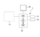
初めに、図1を参照して、本開示における眼底画像観察システムを説明する。実施形態において、眼底画像観察システムは、被検眼の眼底に対して蛍光造影撮影を行う。また、その蛍光造影撮影で得られた複数フレームの画像の中から、観察または診断に適した一部を抽出し、更には、表示させる。眼底画像観察システムは、コンピュータ1と、眼底撮影装置100と、を含む。コンピュータ1と、眼底撮影装置100とは、有線または無線で接続されており、これにより、通信可能である。本開示に係る眼底画像観察プログラムは、コンピュータ1のプロセッサによって読み出し可能な、不揮発性メモリに格納されている。本実施形態では、眼底撮影装置100と、コンピュータ1とが、別体であるものとして説明するが、2つの装置は、一体化されていてもよい。
First, the fundus image observation system in the present disclosure will be described with reference to FIG. In the embodiment, the fundus image observation system performs fluorescence contrast imaging on the fundus of the eye to be examined. In addition, a part suitable for observation or diagnosis is extracted from the images of a plurality of frames obtained by the fluorescence contrast imaging, and further displayed. The fundus image observation system includes a
<眼底撮影装置>
眼底撮影装置100は、被検眼の眼底に光を照射し、眼底からの戻り光を受光素子によって受光するための撮影光学系(図示せず)を、少なくとも有する。受光素子からの受光信号に基づいて眼底正面画像が形成される。眼底正面画像は、眼底撮影装置100の画像処理回路(例えば、ICおよびプロセッサ等)によって形成される。なお、画像処理回路は、眼底撮影装置100に備え付けされている必要はなく、例えば、コンピュータ1の画像処理回路が、眼底撮影装置100の画像処理回路を兼ねていてもよい。
<Fundus photography device>
The
本実施形態において、眼底撮影装置100は、眼底正面画像の1種として、蛍光造影画像を撮影可能であってもよい。また、他にも、眼底正面画像として、反射画像を撮影可能であってもよい。蛍光造影画像は、眼底血管に投与された蛍光造影剤の蛍光発光による撮影画像である。反射画像は、眼底に照射した照明光の眼底反射光による撮影画像である。
In the present embodiment, the
眼底撮影装置100の撮影光学系は、蛍光造影画像と、反射画像とを、同時に撮影可能であってもよい。ここでいう同時は、完全同時に限定されるものではなく、若干の時間差が許容されてもよい。時間差は、例えば、2種類の眼底正面画像が撮影される間に、有意な眼の動きが生じない程度の範囲で設定されてもよい。
The photographing optical system of the
眼底撮影装置100は、例えば、インドシアニングリーン造影撮影(ICGA)、および、フルオレセイン造影撮影(FA)、のいずれかの撮影方法で、蛍光造影画像を撮影するものであってもよい。2種類の造影剤を同時に静注し、2種類の蛍光造影画像を同時に撮影してもよい。また、眼底撮影装置は、赤外光による反射画像(以下、「IR画像」と称する)、および、可視光による反射画像(以下、「可視光画像」と称する)のいずれかを撮影可能であってもよい。また、更に、自発蛍光画像を撮影可能であってもよい。
The
特に断りが無い限り、以下の説明において、眼底撮影装置100は、SLO(走査型レーザー検眼鏡:Scanning Laser Ophthalmoscope)であるものとする。但し、必ずしもこれに限定されるものではなく、例えば、眼底カメラ等、蛍光による眼底正面画像を撮影する機能を持つ、各種の装置であってもよい。なお、眼底撮影装置100は、光干渉断層計(OCT:Optical Coherence Tomography)、視野計などの他の眼科装置と一体化された装置であってもよい。蛍光造影画像と反射画像との同時撮影が可能なSLOの詳細な光学構成については、種々の公知文献があるので、そちらを参照されたい(例えば、本出願人による『特開2016−59399号公報』等)。
Unless otherwise specified, in the following description, the
<コンピュータ>
コンピュータ1は、少なくとも、眼底撮影装置100によって撮影される各種の眼底正面画像を取得し、モニタ80に表示させる。コンピュータ100は、少なくとも、演算制御部(以下、「制御部」と省略する)70を備える。制御部70は、図1に例示するように、CPU、RAM、および、ROM等によって構成されてもよい。制御部70は、眼底正面画像の表示制御のほか、眼底正面画像に関する各種処理を、眼底画像観察プログラムに基づいて実行する。
<Computer>
The
図1に示すように、コンピュータ1の制御部70は、データバス等を介して、メモリ71、操作部75、モニタ80、および、眼底撮影装置100等と接続される。
As shown in FIG. 1, the
本実施形態において、メモリ71は、不揮発性の記憶装置である。例えば、ハードディスク,フラッシュメモリ等が、メモリ71として適用可能である。本実施形態において、眼底画像観察プログラムは、メモリ71に予め記憶されている。メモリ71は、書き換え可能であってもよい。この場合、以下の実施例において説明するように、メモリ71には、眼底撮影装置100から取得される各種の眼底正面画像が記憶されてもよい。但し、眼底正面画像は、眼底画像観察プログラムが記憶されたメモリとは、別体のメモリ(図示せず)に記憶されてもよい。
In this embodiment, the
操作部75は、コンピュータ1の入力インターフェイスである。制御部70は、操作部75への操作入力に応じた信号を受け付ける。操作部75としては、種々のデバイスが考えられる。例えば、タッチパッド、マウス、および、キーボード等の少なくともいずれかが、操作部75として利用されてもよい。なお、操作部75は、眼底撮影装置100の入力インターフェイスとして兼用されてもよい。なお、眼底撮影装置100の入力インターフェイス(操作部)として、眼底撮影装置100に備え付けのジョイスティック、および、スイッチ等が、眼底撮影装置100に設けられていてもよい。
The
モニタ80は、本実施形態において、眼底撮影装置100によって撮影された画像の表示部(表示デバイス)として利用される。モニタ80は、例えば、汎用のモニタあってもよいし、装置に備え付けのモニタであってもよい。モニタ80に代えて、ヘッドマウントディスプレイ等の他の表示デバイスが、表示部として利用されてもよい。
In the present embodiment, the
<動作説明>
以下、上記のような構成を持つ、眼底画像観察システムの動作を説明する。
<Operation explanation>
Hereinafter, the operation of the fundus image observation system having the above configuration will be described.
<蛍光造影撮影>
被検者に造影剤を静注した場合、眼底の血管内に流入する造影剤の量は、静注から一定時間経過後に急激に増大し、その後に徐々に減少する。静注直後の造影初期では、造影剤は、太い血管→細い血管の順で流入してゆき、眼底での蛍光発光の状態の変化は、大きく、且つ、速やかである。一方、造影剤が注入されてから、更に時間が経過した造影中期、造影後期においては、造影剤が血管内に十分に行き渡っているので、眼底での蛍光発光の状態の変化は少なくなる。
<Fluorescence contrast photography>
When a contrast medium is intravenously injected into a subject, the amount of the contrast medium flowing into the blood vessels of the fundus rapidly increases after a certain period of time has passed from the intravenous injection, and then gradually decreases. In the initial stage of contrast medium immediately after intravenous injection, the contrast medium flows in the order of thick blood vessels → thin blood vessels, and the change in the state of fluorescence emission at the fundus is large and rapid. On the other hand, in the middle stage and the late stage of the contrast medium, which is more time after the injection of the contrast medium, the contrast medium is sufficiently distributed in the blood vessels, so that the change in the state of fluorescence emission in the fundus is small.
そこで、造影初期から造影後期までの一連の蛍光造影撮影において、造影初期では、蛍光造影画像の連続撮影が、撮影トリガ信号(本実施形態における第1の撮影トリガ信号)に基づいて行われてもよい。連続撮影では、撮影トリガ信号が出力されてから、少なくとも10秒から数分或いは数十分の期間、継続的に蛍光造影画像が撮影される。つまり、当該期間の間、眼底に光が投光され、その戻り光が受光素子に受光される。連続撮影の結果、撮影画像群が、眼底撮影装置100によって取得される。
Therefore, in a series of fluorescence contrast imaging from the initial stage of contrast enhancement to the latter stage of contrast enhancement, even if continuous imaging of the fluorescence contrast image is performed based on the imaging trigger signal (first imaging trigger signal in the present embodiment) at the initial imaging stage. good. In continuous imaging, a fluorescence contrast image is continuously captured for a period of at least 10 seconds to several minutes or several tens of minutes after the imaging trigger signal is output. That is, during this period, light is projected onto the fundus and the return light is received by the light receiving element. As a result of continuous shooting, a group of shot images is acquired by the
撮影画像群には、撮影トリガ信号(本実施形態における第1の撮影トリガ信号)の出力タイミング以降に一定周期で撮影された連続的な複数フレームの蛍光造影画像(蛍光による眼底正面画像)が含まれる。SLOでは、眼底の所定範囲で光が周期的に走査されることにより、所定範囲内で光が一通り(つまり、一周期分)走査される毎に、1フレームの撮影画像を得ることが可能である。撮影画像群は、撮影期間中の各周期の眼底走査で得られた蛍光造影画像で構成されていてもよいし、1周期とばし、(又は、2周期とばし、3周期とばし、・・・n周期とばし、でもよい)の眼底走査で得られた蛍光造影画像で構成されていてもよい。眼底撮影装置100によって、少なくとも毎秒、数フレームの撮影画像が得られる。
The captured image group includes a continuous plurality of frames of fluorescence contrast images (frontal image of the fundus due to fluorescence) captured at regular intervals after the output timing of the capture trigger signal (first capture trigger signal in the present embodiment). Is done. In SLO, by periodically scanning the light in a predetermined range of the fundus, it is possible to obtain a captured image of one frame every time the light is scanned once in a predetermined range (that is, for one cycle). Is. The captured image group may be composed of fluorescence contrast images obtained by scanning the fundus of each cycle during the imaging period, skipping one cycle (or skipping two cycles, skipping three cycles, ... n cycles). It may be composed of a fluorescence contrast image obtained by a fundus scan (which may be skipped). The
なお、以下では、撮影画像群に含まれる各々の蛍光造影画像を、以下、便宜上「フレーム画像」と称する場合がある。 In the following, each fluorescence contrast image included in the captured image group may be hereinafter referred to as a “frame image” for convenience.
また、一連の蛍光造影撮影において、造影中期および造影後期では、撮影トリガ信号(本実施形態における第2の撮影トリガ信号)の出力に基づき、蛍光造影画像が単発的に撮影されてもよい。この場合、撮影トリガ信号の出力直後に、蛍光造影画像の静止画像が単発的に撮影される。ここでいう、「単発的な撮影」とは、撮影トリガ信号の出力を契機に、少なくとも1枚の予め定められた枚数の蛍光造影画像が得られることである。なお、「単発的な撮影」では、連続撮影に比べて、短い時間で撮影が行われる。1回の撮影トリガ信号につき、得られる蛍光造影画像は、多くても十枚程度にとどめることが好ましい。「単発的な撮影」の結果として得られる蛍光造影画像を、以下、便宜上「造影静止画像」と称する。造影静止画像は、連続造影撮影で得られるフレーム画像に対して画素数が多い(例えは、解像度の高い)画像であってもよい。 Further, in a series of fluorescence contrast imaging, a fluorescence contrast image may be taken in a single shot based on the output of the imaging trigger signal (second imaging trigger signal in the present embodiment) in the middle stage and the late stage of imaging. In this case, immediately after the output of the imaging trigger signal, a still image of the fluorescence contrast image is captured in a single shot. The term "single-shot imaging" as used herein means that at least one predetermined number of fluorescence contrast images can be obtained by using the output of the imaging trigger signal as an opportunity. In "single-shot shooting", shooting is performed in a shorter time than continuous shooting. It is preferable that the number of fluorescence contrast images obtained for each imaging trigger signal is at most about ten. The fluorescence contrast image obtained as a result of "single-shot imaging" is hereinafter referred to as "contrast still image" for convenience. The contrast-enhanced still image may be an image having a larger number of pixels (for example, a higher resolution) than the frame image obtained by continuous contrast-enhanced imaging.
なお、必ずしもこれに限られるものではなく、造影初期において造影静止画像の撮影が行われてもよく、また、造影後期において、連続造影撮影が行われてもよい。 It should be noted that the present invention is not necessarily limited to this, and a contrast-enhanced still image may be taken in the early stage of contrast enhancement, and continuous contrast-enhanced imaging may be performed in the latter stage of contrast enhancement.
一連の蛍光造影撮影の結果として取得される複数の蛍光造影画像の一部または全部は、加算画像であってもよい。FA、ICGAのいずれにおいても、眼底からの蛍光は微弱であり、それは、造影初期、造影後期においては特に顕著である。このため、例えば、連続する複数フレーム分の蛍光造影画像を取得し、それらを加算(加算平均、加重平均等でもよい)することで、良好な蛍光造影画像を得るようにしてもよい。 Part or all of the plurality of fluorescence contrast images obtained as a result of a series of fluorescence contrast imaging may be additive images. In both FA and ICGA, the fluorescence from the fundus is weak, which is particularly remarkable in the early stage of contrast enhancement and the late stage of contrast enhancement. Therefore, for example, a good fluorescence contrast image may be obtained by acquiring fluorescence contrast images for a plurality of consecutive frames and adding them (additional averaging, weighted average, etc.).
眼底装置100は、各々の蛍光造影画像と同時に、反射画像を撮影する。詳細は後述するが、反射画像は、各々の蛍光造影画像の位置関係を対応付けるために利用可能である。
The
次に、図2を参照し、蛍光造影撮影における装置動作の具体例を説明する。 Next, with reference to FIG. 2, a specific example of the operation of the device in fluorescence contrast imaging will be described.
[t0:アライメントおよび撮影条件の設定]
まず、検者は、被検眼に対する装置のアライメントを行い、併せて、撮影条件を設定する。この場合に設定される撮影条件には、励起光として眼底に照射する光の波長についての条件が少なくとも含まれる。例えば、FAの場合は、青色、又は、緑色の光が励起光として設定され、ICGAの場合は、赤外域の光が励起光として設定される。FA,ICGAが同時に行われる場合、それぞれに対応した2種類の波長域が、励起光として設定される。更に、本実施形態では、第2の赤外域の光が、眼底に照射される光として、更に設定される。第2の赤外域の光は、眼底観察用の光、および、反射画像を得るための光として、兼用される。なお、第2の赤外域は、ICG励起用の赤外域とは波長域が異なる。
[T0: Alignment and shooting condition settings]
First, the examiner aligns the device with respect to the eye to be inspected, and also sets the imaging conditions. The imaging conditions set in this case include at least conditions regarding the wavelength of the light that irradiates the fundus of the eye as excitation light. For example, in the case of FA, blue or green light is set as the excitation light, and in the case of ICGA, light in the infrared region is set as the excitation light. When FA and ICGA are performed at the same time, two types of wavelength ranges corresponding to each are set as excitation light. Further, in the present embodiment, the light in the second infrared region is further set as the light to be applied to the fundus of the eye. The light in the second infrared region is also used as light for observing the fundus and light for obtaining a reflected image. The wavelength region of the second infrared region is different from that of the infrared region for ICG excitation.
[t1:蛍光造影撮影の開始]
アライメントおよび撮影条件の設定が完了したら、検者は、被検者に造影剤を静注する。また、同時に(又は直後に)、一連の蛍光造影撮影を開始させるための操作入力を、眼底撮影装置100の入力インターフェイスに対して行う。その結果、眼底撮影装置100において、蛍光造影撮影が開始される。
[T1: Start of fluorescence contrast imaging]
After the alignment and imaging conditions have been set, the examiner intravenously injects the contrast medium into the subject. At the same time (or immediately after), an operation input for starting a series of fluorescence contrast imaging is performed on the input interface of the
まず、眼底撮影装置100の造影タイマが作動される。造影タイマは、造影開始からの時間経過を計測する時間計測手段である。つまり、造影時期が、造影タイマによって管理される。一連の蛍光造影撮影で撮影される各々の眼底正面画像(蛍光造影画像および反射画像)には、各々の撮影タイミングにおける造影タイマの計測時間が、対応付けてメモリに記憶される。
First, the contrast timer of the
一連の蛍光造影撮影の間、眼底には、継続的に、励起光が照射(SLOでは、更に、走査)され、更に、励起光の照射に基づく眼底からの蛍光による眼底画像が、眼底撮影装置100によって、逐次取得されてもよい。逐次取得される画像は、観察画像(リアルタイムな動画像)として、モニタ(例えば、モニタ80)に表示されてもよい。これにより、撮影範囲、および、固視のズレを、反射画像から確認することができる。そして、検者は、蛍光による観察画像を確認しながら、適切なタイミングで、トリガ操作を行うことが可能となる。 During a series of fluorescence imaging, the fundus is continuously irradiated with excitation light (further scanning in SLO), and a fundus image by fluorescence from the fundus based on the irradiation of the excitation light is obtained by the fundus photography apparatus. By 100, it may be acquired sequentially. The images sequentially acquired may be displayed on a monitor (for example, monitor 80) as an observation image (real-time moving image). As a result, the shooting range and the deviation of the fixation can be confirmed from the reflected image. Then, the examiner can perform the trigger operation at an appropriate timing while confirming the observation image by fluorescence.
[t1〜t2:造影初期]
本実施形態では、一連の蛍光造影撮影の開始タイミングから、連続造影撮影が開始される。つまり、連続造影撮影の開始操作に基づいて、連続造影撮影の撮影トリガ信号が出力される。連続造影撮影の結果として、複数フレームの蛍光造影画像を含む撮影画像群が、メモリに記憶される。本実施形態では、各々の蛍光造影画像と同時に撮影された複数フレームの反射画像が、メモリに記憶される。連続造影撮影は、開始から一定時間経過後に自動的に終了してもよいし、眼底撮影装置100の入力インターフェイスに対する所定操作に基づいて、手動で終了してもよいし、その他の終了条件を満たしたときに終了してもよい。
[T1-t2: Initial stage of contrast enhancement]
In the present embodiment, continuous contrast imaging is started from the start timing of a series of fluorescence contrast imaging. That is, the imaging trigger signal for continuous contrast imaging is output based on the start operation of continuous contrast imaging. As a result of continuous contrast imaging, a group of captured images including a plurality of frames of fluorescence contrast images is stored in the memory. In the present embodiment, the reflected images of a plurality of frames taken at the same time as each fluorescence contrast image are stored in the memory. The continuous contrast imaging may be automatically terminated after a certain period of time has elapsed from the start, may be terminated manually based on a predetermined operation on the input interface of the
本実施形態では、逐次取得されるフレーム画像(蛍光造影画像)が、モニタ80にリアルタイムな動画として表示される。併せて、各フレーム画像と共に撮影される、反射画像も動画として表示されてもよい。撮影範囲、および、固視のズレを、反射画像から確認することができる。
In the present embodiment, the frame images (fluorescence contrast images) that are sequentially acquired are displayed on the
連続造影撮影の間に発せられるトリガ信号(第3のトリガ信号)の出力タイミングで得られたフレーム画像が、キーフレーム(又は、その候補)として選択されてもよい。この場合、連続造影撮影の結果として得られる撮影画像群の中からキーフレーム(又は、その候補)を特定するための情報(キーフレーム特定情報)が、メモリに記憶される。 A frame image obtained at the output timing of a trigger signal (third trigger signal) emitted during continuous contrast imaging may be selected as a key frame (or a candidate thereof). In this case, information (keyframe identification information) for identifying a keyframe (or a candidate thereof) from a group of captured images obtained as a result of continuous contrast imaging is stored in the memory.
例えば、連続造影撮影の間にキーフレームを選択するためのトリガ信号は、眼底撮影装置100の入力インターフェイスに対する操作に基づいて出力されてもよい。本実施形態では、検者が、動画像において所望の造影状態が確認されたタイミングで、上記の操作(以下、この操作を、「トリガ操作」と称する)を入力インターフェイスに対して行うことで、眼底撮影装置100に対して第3のトリガ信号が入力される。
For example, a trigger signal for selecting a keyframe during continuous contrast imaging may be output based on an operation on the input interface of the
本実施形態において、「キーフレーム」は、連続造影撮影の結果として得られる複数のフレーム画像のうち、所望の造影状態を示す画像である。例えば、診断において有用である、CNV(脈絡膜新生血管)への造影剤が流入していく数秒間の間に形成されるフレーム画像等が、キーフレームの1つとして選択されてもよい。1回の連続造影撮影に対し、複数フレームのキーフレームが選択可能である。本実施形態では、連続造影撮影中に、トリガ操作が行われる毎に、新たなキーフレーム(又は、その候補)が追加的に選択される。 In the present embodiment, the "key frame" is an image showing a desired contrast state among a plurality of frame images obtained as a result of continuous contrast imaging. For example, a frame image or the like formed within a few seconds when the contrast medium flows into the CNV (choroidal neovascularization), which is useful in diagnosis, may be selected as one of the key frames. Multiple frames of keyframes can be selected for one continuous contrast imaging. In the present embodiment, a new key frame (or a candidate thereof) is additionally selected each time a trigger operation is performed during continuous contrast imaging.
「キーフレーム特定情報」には、各種情報を利用可能である。例えば、キーフレーム(又は、その候補)が撮影された時間を示す撮影時間情報であってもよい。撮影時間情報は、キーフレーム(又は、その候補)の取得日時を示してもよいし、キーフレーム(又は、その候補)の取得時における造影タイマの計測時間を示してもよい。また、フレーム画像に連番が付される場合は、キーフレーム(又は、その候補)に付される連番情報を、キーフレーム特定情報として利用し得る。他にも、ここで例示した以外の情報を、キーフレーム特定情報として利用可能である。 Various types of information can be used for "keyframe specific information". For example, it may be shooting time information indicating the time when the key frame (or its candidate) was shot. The shooting time information may indicate the acquisition date and time of the key frame (or its candidate), or may indicate the measurement time of the contrast timer at the time of acquisition of the key frame (or its candidate). When the frame image is numbered serially, the serial number information attached to the key frame (or its candidate) can be used as the key frame specific information. In addition, information other than those illustrated here can be used as keyframe specific information.
以下では、キーフレームの候補が、連続撮影中のトリガ操作に基づいて選択される実施例を、主に説明する。選択された候補を、キーフレームとして最終的に選択するか否かについては、一連の蛍光造影撮影の完了後に、改めて決定可能である(詳細は後述する)。 In the following, an embodiment in which keyframe candidates are selected based on a trigger operation during continuous shooting will be mainly described. Whether or not the selected candidate is finally selected as a key frame can be determined again after the completion of the series of fluorescence contrast imaging (details will be described later).
なお、上記のトリガ操作は、造影静止画像の撮影を開始するときの操作と同じであってもよい。例えば、レリーズボタン(眼底撮影装置100の入力インターフェイスの一種)を押下することが、トリガ操作であってもよい。 The above-mentioned trigger operation may be the same as the operation when starting the shooting of the contrast-enhanced still image. For example, pressing the release button (a type of input interface of the fundus photography device 100) may be a trigger operation.
以上のようにして、造影初期において、連続造影撮影が行われる。 As described above, continuous contrast imaging is performed at the initial stage of contrast enhancement.
[t2〜t3:造影中期・後期]
次いで、数分から数十分程度の時間を適宜おいて、造影静止画像の撮影が行われる。この撮影に際し、眼底撮影装置100は、励起光に基づく、或いは、赤外域の光に基づく観察画像を取得し、モニタ80に表示させる。造影中期、造影後期における任意のタイミングで、造影状態、又は、撮影範囲を観察画像を用いて確認しながら、撮影操作を行う(例えば、レリーズボタンを押下する)。撮影操作に基づいて、眼底撮影装置100には、撮影トリガ信号(第2の撮影トリガ信号)が入力される。これにより、眼底撮影装置100は、造影静止画像を取得する。このとき、励起光と共に、反射画像撮影用の光を眼底に投光し、造影静止画像と同時に、反射画像を得る。このようして、撮影中期・後期では、撮影操作毎に、造影静止画像および反射画像が同時に取得され、メモリに記憶される。
[t2 to t3: middle / late contrast enhancement]
Then, a contrast-enhanced still image is taken at an appropriate time of several minutes to several tens of minutes. At the time of this imaging, the
<撮影結果の取得>
以上のようにして眼底撮影装置100によって撮影された、蛍光造影画像、および、反射画像は、コンピュータ1のプロセッサからアクセス可能なメモリ(ここでは、メモリ71)に記憶される。このとき、一連の蛍光造影撮影で得られた複数フレームの蛍光造影画像(本実施形態では、更に、反射画像)が含まれる画像群データが、メモリ71に記憶される。例えば、1つの画像群データにつき、1つのファイルまたは1つのフォルダが、メモリ71に生成され、そのファイルまたはフォルダ内に、一連の蛍光造影撮影で得られた各画像のデータが含まれてもよい。本実施形態において、画像群データは、一連の蛍光造影撮影毎に1つ生成されるものとして説明するが、撮影日毎に1つ生成されるものであってもよい。
<Acquisition of shooting results>
The fluorescence contrast image and the reflection image taken by the
前述したように、本実施形態では、各々の蛍光造影画像および反射画像が撮影された時の造影タイマの計測時間を示す情報が、更に、メモリ71に記憶される。
As described above, in the present embodiment, information indicating the measurement time of the contrast timer when each fluorescence contrast image and reflection image is taken is further stored in the
また、連続造影撮影の途中で、キーフレーム(又は、その候補)を選択するための第3のトリガ信号が出力され、その出力に基づいてキーフレーム特定情報が生成された場合は、キーフレーム特定情報が、連続造影撮影で得られた撮影画像群のデータと共に、メモリ71に格納される。
In addition, when a third trigger signal for selecting a key frame (or a candidate thereof) is output during continuous contrast imaging and key frame identification information is generated based on the output, key frame identification is performed. The information is stored in the
<撮影結果の確認画面>
コンピュータ1の制御部70は、一連の蛍光造影撮影毎に、又は、撮影日毎に、被検眼の蛍光造影画像が一覧表示される確認画面(本実施形態では、キーフレーム選択画面と兼用)を生成し、確認画面をモニタ80に表示させる。
<Confirmation screen of shooting results>
The
確認画面では、一連の蛍光造影撮影において、各々の撮影トリガ信号毎に得られた複数フレームの蛍光造影画像を含む画像群データから、任意の造影時期に撮影された蛍光造影画像が選択され、選択された画像が表示可能である。本実施形態では、操作部75を介して造影時期の選択操作を受け付け、その造影時期に対応する蛍光造影画像が、確認画面において表示される画像として、選択される。複数の蛍光造影画像が選択された場合、選択された各々の画像は、確認画面において、並べられて表示されてもよいし、1つの領域にて切換表示されてもよい。この場合、造影静止画像と撮影画像群に含まれるフレーム画像とは、混在した状態で、時系列に並べられ、或いは、時系列に、切り替えられる。換言すれば、各々のフレーム画像の造影時期と各々の造影静止画像の造影時期とを1つの時系列として、該時系列における任意の造影時期の画像が、選択され、更に、表示される。
On the confirmation screen, in a series of fluorescence contrast imaging, the fluorescence contrast image captured at an arbitrary imaging time is selected and selected from the image group data including the fluorescence contrast images of a plurality of frames obtained for each imaging trigger signal. The image can be displayed. In the present embodiment, the operation for selecting the contrast time is received via the
確認画面には、造影時期の選択操作を受け付けるためのコントロール(本実施形態における「操作部」)が設けられていてもよい。例えば、コントロールとして、一連の蛍光造影撮影の時系列に対応するスライダが、設けられていてもよい。この場合、スライダのレバーの位置と対応する造影時期の画像が、確認画面に表示される。 The confirmation screen may be provided with a control (“operation unit” in the present embodiment) for receiving a selection operation of the contrast time. For example, as a control, a slider corresponding to a time series of a series of fluorescence contrast imaging may be provided. In this case, the image of the contrast time corresponding to the position of the lever of the slider is displayed on the confirmation screen.
造影時期の選択操作には、必ずしもスライダを介した操作である必要はない。例えば、スライダ以外のコントロールがモニタ上に表示されてもよい。また、モニタ80上のコントロールを介した選択操作である必要はなく、例えば、キーボードにおける特定のキー(例えば、「↑」「↓」「←」「→」のキー)の操作、マウスのホイール操作等の各種操作が、造影時期の選択操作として利用可能である。
The operation for selecting the contrast time does not necessarily have to be an operation via a slider. For example, controls other than sliders may be displayed on the monitor. Further, it is not necessary to perform the selection operation via the control on the
また、確認画面において一覧表示される造影静止画像とフレーム画像との各々には、各々の造影時期を示す時間情報が、対応付けて表示される。時間情報を参照することで、多くの蛍光造影画像の中から、検者が所望する造影状態が示された画像を探し出すことが容易となる。 In addition, time information indicating each contrast time is displayed in association with each of the contrast still image and the frame image displayed in a list on the confirmation screen. By referring to the time information, it becomes easy for the examiner to find an image showing the desired contrast state from among many fluorescence contrast images.
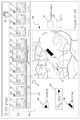
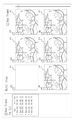
図3は、確認画面(キーフレーム選択画面と兼用)の実施例の1つであり、FAによる撮影結果が示されている。図3では、画面上部の所定位置にサムネイル表示領域210が設けられている。そして、サムネイル表示領域210において、一連の蛍光造影撮影で取得された、造影静止画像とフレーム画像とが、それぞれのサムネイル211,212によって、時系列に並べられて表示される。なお、図3において、符号211は、フレーム画像のサムネイルを示し、符号212は、造影静止画像のサムネイルを示している。
FIG. 3 is one of the examples of the confirmation screen (also used as the key frame selection screen), and shows the shooting result by FA. In FIG. 3, a
図3の確認画面では、各々のサムネイル211,212の近傍(図3では、下部)に、各々の造影時期が、時間情報によって表示される。 On the confirmation screen of FIG. 3, each contrast time is displayed by time information in the vicinity of each thumbnail 211,212 (lower part in FIG. 3).
サムネイル表示領域210には、撮影画像群に含まれる複数フレームのフレーム画像のうち、一部のフレーム画像が抽出され、(サムネイル211として)表示される。サムネイル表示領域210に表示されるフレーム画像の枚数は、予め定められていてもよい。例えば、撮影画像群毎に一定の枚数であってもよいし、連続造影撮影の撮影時間または撮影画像群に含まれるフレーム画像の枚数と対応した予め定められた枚数であってもよい。また、サムネイル表示領域210に表示されるフレーム画像の枚数は、検者の選択操作に基づいて決定されてもよい。この場合の具体例として、連続造影撮影中に(図2における[t1〜t2]の期間を参照)キーフレームの候補として(「キーフレームとして」でもよい)選択されたフレーム画像の各々が、サムネイル211としてサムネイル表示領域210に表示されてもよい。この場合、更に、連続造影撮影中に、キーフレームの候補を選択するためのトリガ操作が行われなかった場合は、予め定められた枚数のフレーム画像が自動的に抽出され、サムネイル211としてサムネイル表示領域210に表示されてもよい。また、一連の蛍光造影撮影において、連続造影撮影が複数回行われた場合、連続造影撮影毎(第1の撮影トリガ信号毎)に少なくとも1枚のフレーム画像が抽出され、サムネイル表示領域210において、表示されてもよい。また、サムネイル表示領域210において、抽出および表示されるフレーム画像の枚数は、変更可能であってもよい。
In the
制御部70は、確認画面において表示される造影静止画像とフレーム画像との少なくとも一方に、造影静止画像とフレーム画像とを区別するための識別用グラフィックを対応づけて表示させる。例えば、図3では、サムネイル211,212のうち、サムネイル211のみに対して、グラフィック213が付されて表示されている。図3において、グラフィック213は、写真フィルムの耳を模した図形であり、各分野で動画像のサムネイルを表す際に慣用的に利用されている。これにより、検者は、サムネイル211を、フレーム画像(すなわち、多数のフレームからなる撮影画像群の中から抽出された画像)のサムネイルであると、直感的に把握できる。
The
また、図3の確認画面には、サムネイル表示領域210の近傍(図3では、下部)に、スライダ220が配置されている。スライダ220は、本実施形態において、造影時期の選択操作を受け付けるためのコントロールである。ポインティングデバイス(操作部75の一種)を用いたドラッグ操作等によってスライダ220のレバーが移動されると、レバーの位置に連動したサムネイル211,212が表示される。
Further, on the confirmation screen of FIG. 3, a
図3の確認画面には、サムネイル表示領域210とは異なる位置に、詳細表示領域230が設けられている。詳細表示領域230では、サムネイルと比べて、大きなサイズおよび高い画素数のいずれかで、蛍光造影画像が表示される。検者は、詳細表示領域230を確認することで、所望の造影時期における造影状態を詳細に確認することができる。
On the confirmation screen of FIG. 3, a
詳細表示領域230に表示される蛍光造影画像は、いずれかのサムネイル211,212と対応する(同一の画像データに基づく)ものであってもよい。この場合、各サムネイル211,212のうち、検者の選択操作に基づいて詳細表示の対象となるサムネイルが選択されてもよい。選択操作は、例えば、所望のサムネイル211,212を、ポインティングデバイスを介してクリックまたはタップすること、又は、詳細表示領域230へドラッグ&ドロップすること、等が例示される。但し、選択操作は、これ以外の操作方法であってもよい。図3に示すように、選択中(詳細表示中)のサムネイル211,212には、その他のサムネイルと区別するためのグラフィック214が、対応づけて表示されてもよい。
The fluorescence contrast image displayed in the
<画像間の位置合わせ>
図3の確認画面では、位置合わせボタン225が配置されている。位置合わせボタン225選択されることで、確認画面に表示される各々の蛍光造影画像が、位置合わせされる。その結果、ある蛍光造影画像を基準として、他の蛍光造影画像の撮影位置のずれが各々補正され、表示される。ところで、各々の蛍光造影画像には、造影状態の違いがあるので、画像間の位置合わせが難しい場合がありうる。そこで、本実施形態では、例えば、蛍光造影画像と同時に撮影される反射画像を利用して、位置合わせが行われる。位置合わせの詳細は、例えば、本出願による特開2016−59400号公報等を参照されたい。
<Alignment between images>
On the confirmation screen of FIG. 3, the
本実施形態において、位置合わせは、いずれの蛍光造影画像(あるいは、それと同時に撮影された反射画像)が、位置合わせの基準として利用されてもよい。キーフレームが選択済みの場合は、例えば、造影時期が最も早いキーフレームを基準として位置合わせが行われてもよい。また、詳細表示の対象として選択中のフレーム画像または造影静止画像が、位置合わせの基準として利用されてもよい。この場合、ボタン225が選択された時点で、詳細表示領域230に表示されていた画像が、位置合わせの基準である。
In the present embodiment, for alignment, any fluorescence contrast image (or a reflection image taken at the same time) may be used as a reference for alignment. When the key frame is already selected, for example, the alignment may be performed with reference to the key frame having the earliest contrast time. Further, the frame image or the contrast-enhanced still image selected as the target of the detailed display may be used as the alignment reference. In this case, the image displayed in the
位置合わせが行われた場合、サムネイル表示領域210および詳細表示領域230に表示される画像が、基準とされた蛍光造影画像に位置合わせされた状態で表示される。このため、確認画面において蛍光造影画像を比較しやすくなる。
When the alignment is performed, the images displayed in the
<蛍光造影画像における注目部位の強調>
本実施形態では、詳細表示領域230に表示される蛍光造影画像おいて、注目部位の強調表示が行われてもよい。強調表示は、例えば、注目部位の拡大表示によって行われてもよいし、注目部位、或いは、その近傍にマーカーが重畳されることによる重畳表示によって行われてもよい。強調表示の態様は、拡大表示およびマーカーの重畳表示に限られるものではなく、他の種々の強調表示の態様を適用可能である。例えば、注目部位とそれ以外とが異なる態様で表示されることで、強調表示が行われてもよい。
<Emphasis of the area of interest in the fluorescence contrast image>
In the present embodiment, the highlighting of the region of interest may be performed in the fluorescence contrast image displayed in the
強調表示は、少なくとも、注目部位(またはその近傍)の位置を特定するための情報(以下、「注目部位位置情報」と称す)に基づいて行われる。注目部位位置情報は、一連の蛍光造影撮影で得られた複数の蛍光造影画像のうち、いずれか一枚の蛍光造影画像に対する注目部位を特定する情報である。注目部位位置情報は、例えば、ある蛍光造影画像上、または、その蛍光造影画像と同時に撮影された反射画像上における位置情報であってもよい。注目部位の位置は、モニタ80に表示される蛍光造影画像または反射画像に対し、検者が選択した任意の位置であってもよい。また、蛍光造影画像または反射画像において予め定められた位置、または、蛍光造影画像または反射画像から検出された病変部等の位置であってもよい。以下では、検者の操作入力に基づいて、注目部位が設定される場合を説明する。
The highlighting is performed based on at least information for identifying the position of the region of interest (or its vicinity) (hereinafter, referred to as "location information of the region of interest"). The region of interest position information is information for identifying a region of interest for any one of a plurality of fluorescence contrast images obtained by a series of fluorescence contrast imaging. The position information of the site of interest may be, for example, position information on a certain fluorescence contrast image or on a reflection image taken at the same time as the fluorescence contrast image. The position of the region of interest may be any position selected by the examiner with respect to the fluorescence contrast image or the reflection image displayed on the
詳細表示領域230において、蛍光造影画像の一部が拡大表示されることによって、第1の強調表示が行われる。この場合において、蛍光造影画像上の任意の位置を中心として、拡大可能であってもよい。中心となる位置は、例えば、操作部75を介して入力されてもよい。図3では、例えば、コントロール(操作部)255を選択すると、表示倍率の選択肢がドロップダウン表示され、選択肢の中から、所望の表示倍率が選択可能である。その後、詳細表示領域230上で、拡大時の中心位置を選択することにより、当該位置を中心として、選択された表示倍率で、拡大された蛍光造影画像が、詳細表示領域230に表示される。勿論、拡大する位置の選択手法は、上記したものに限定されるものではない。このように、蛍光造影画像の任意の位置が拡大表示されることで、毛細血管への造影剤の流入、および、新生血管からの造影剤の漏出等といった、微細な部位における造影状態を、検者が確認しやすくなる。この場合、詳細表示領域230に表示される蛍光造影画像における拡大中心位置を示す情報が、注目部位位置情報として、メモリ71に記憶される。また、併せて、拡大倍率が対応付けて、メモリ71に記憶される。
In the
本実施形態では、詳細表示領域230に表示される蛍光造影画像に対し、マーカーMを重畳可能であってもよい。例えば、マーカーMは、蛍光造影画像上で、操作部75への操作入力に基づいて指定された位置に重畳されてもよい。マーカーMのグラフィックは、予め定められていてもよいし、操作部75に対する操作に応じてフリーハンドで描画されてもよい。例えば、自由曲線が、フリーハンドで描画されるグラフィックの典型例である。図3では、例えば、ボタン260が選択されると、詳細表示領域230に対して、マーカーMを描画可能(配置可能)となる。検者が注目する部位等に、ポインタを合わせて、マーカーMの配置操作が行われることで、該ポインタの位置に、マーカーMが重畳される。この場合、詳細表示領域230に表示される蛍光造影画像と対応づけられたマーカーMの位置情報が、注目部位位置情報として、メモリ71に記憶される。
In the present embodiment, the marker M may be superposed on the fluorescence contrast image displayed in the
<詳細表示領域に表示される画像の切換>
一連の蛍光造影撮影で取得された複数の蛍光造影画像のうち詳細表示領域230に表示される蛍光造影画像は、ある画像(以下、「第1の画像」と称する)から、他の画像(以下「第2の画像」と称する)へと切換可能である。第1および第2の画像は、それぞれが、一連の蛍光造影撮影で取得された複数の蛍光造影画像の中から、検者による選択操作に基づいて任意に選択されてもよい。また、予め定められた所定の規則に基づいて選択されてもよい。ここでいう、所定の規則としては、例えば、各蛍光造影画像の撮影順序に関する規則であってもよい。例えば、スライドショー表示のように、一連の蛍光造影撮影で取得された複数の蛍光造影画像が、撮影順に、所定時間毎に、順々に切り替えられて表示されてもよい。図3の例では、ボタン250の選択操作に基づいて、上記のスライドショー表示が行われる。また、図3の例では、例えば、各々のサムネイル211,212の中から、詳細表示中のサムネイル(つまり、グラフィック214が対応づけられたサムネイル)とは異なる任意のサムネイルが、新たな詳細表示の対象として、検者による選択操作に基づいて選択可能である。
<Switching of images displayed in the detailed display area>
Of the plurality of fluorescence contrast images acquired by a series of fluorescence contrast imaging, the fluorescence contrast image displayed in the
[強調の再現]
詳細表示領域230において表示される画像が、第1の画像から第2の画像へと切り替えられる場合において、第1の画像において注目部位の強調表示が行われていたときには、第1の画像における注目部位の強調が、第2の画像においても再現されてもよい。この場合、第1の画像における注目部位位置情報に基づいて、第1の画像と同じ注目部位が、第2の画像において強調される。より具体的には、第1の画像と同時に撮影された第1の反射画像と、第2の画像と同時に撮影された第2の反射画像と、の間で位置合わせが行われる。第1の画像と第1の反射画像、第2の画像と第2の反射画像、はそれぞれの撮影範囲が同じであるので、位置合わせの結果として、第1の反射画像における注目部位の位置が、第2の反射画像上で特定できる。その結果、注目部位における時間変化を、検者は容易に把握することができる。
[Reproduction of emphasis]
When the image displayed in the
<キーフレームの選択:確認画面>
本実施形態では、一連の蛍光造影撮影において得られた複数の蛍光造影画像の中から、所望の造影状態を示すフレームがキーフレームとして、1枚以上選択および設定される。その結果、撮影画像群の中からキーフレームを特定するためのキーフレーム特定情報が、メモリ71に記憶される。一連の蛍光造影撮影に関する画像群データと、その画像群データと対応するキーフレーム特定情報とに基づいて、画像群データの中からキーフレームを抽出して、キーフレームを一覧表示することが可能となる。このような一覧表示は、一連の蛍光造影撮影毎に行われてもよいし、撮影日毎に行われてもよい。このように、一連の蛍光造影撮影で得られた複数フレームの蛍光造影画像の中から、所望の造影状態を示す蛍光造影画像が抽出されたうえで、一覧表示されるので、一連の蛍光造影画像において、観察・診断のポイントとなる造影画像を、検者は良好に確認しやすい。
<Select keyframe: Confirmation screen>
In the present embodiment, one or more frames indicating a desired contrast state are selected and set as key frames from a plurality of fluorescence contrast images obtained in a series of fluorescence contrast imaging. As a result, the key frame identification information for identifying the key frame from the captured image group is stored in the
本実施形態において、キーフレームは、検者の選択操作に基づいて選択および設定されてもよい。一般に、各々の造影タイミングでの特徴的な造影状態を示す蛍光造影画像は、一連の蛍光造影撮影に対して、数枚程度(例えば、10枚未満)であると考えられる。このため、本実施形態では、一連の蛍光造影撮影毎に、数枚程度のキーフレームが選択されることが、想定される。 In this embodiment, keyframes may be selected and set based on the examiner's selection operation. In general, it is considered that the number of fluorescence contrast images showing a characteristic contrast state at each contrast timing is about several (for example, less than 10) for a series of fluorescence contrast imaging. Therefore, in the present embodiment, it is assumed that several keyframes are selected for each series of fluorescence contrast imaging.
しかしながら、多数の蛍光造影画像が、一連の蛍光造影撮影の度に撮影されることが考えられる。例えば、連続造影撮影が行われる場合は、該撮影が数秒程度行われただけでも、数十フレーム以上が生成される。また、撮影ミスを考慮して、撮影回数に余裕を持たせることも考えられる。 However, it is conceivable that a large number of fluorescence contrast images will be taken for each series of fluorescence contrast imaging. For example, when continuous contrast imaging is performed, several tens of frames or more are generated even if the imaging is performed for only a few seconds. It is also conceivable to allow a margin for the number of shootings in consideration of shooting mistakes.
このため、一連の蛍光造影撮影によって得られた全てのフレームを万遍なく検者に示し、その中からキーフレームを選択させることは、検者にとって負担が生じやすいものと考えられる。 Therefore, it is considered that it is easy for the examiner to burden the examiner by showing all the frames obtained by the series of fluorescence contrast imaging evenly to the examiner and having the examiner select a key frame from them.
そこで、本実施形態では、一連の蛍光像造影撮影で得られた複数の蛍光造影画像のうち、確認画面には、一部が抽出されて表示され、表示される画像が、キーフレームとして選択可能となる。つまり、キーフレームの選択操作における選択対象として設定される。 Therefore, in the present embodiment, a part of the plurality of fluorescence contrast images obtained by the series of fluorescence contrast imaging is extracted and displayed on the confirmation screen, and the displayed image can be selected as a key frame. It becomes. That is, it is set as a selection target in the key frame selection operation.
前述したように、連続造影撮影の結果として生成される撮影画像群は、特に多くのフレームが含まれるので、少なくとも撮影画像群の中から確認画面に表示されるフレーム画像の枚数が、制限されることが好ましい。そこで、撮影画像群に含まれるフレーム画像は、予め定められたフレーム間隔で、または、予め定められた枚数だけ、抽出されたものが、確認画面上に表示されてもよい。また、連続造影撮影中のトリガ操作が行われたタイミングで取得されたフレーム画像が、キーフレームの候補として、確認画面上に表示されてもよい。 As described above, since the captured image group generated as a result of continuous contrast imaging includes a particularly large number of frames, at least the number of frame images displayed on the confirmation screen from the captured image group is limited. Is preferable. Therefore, as the frame images included in the captured image group, those extracted at a predetermined frame interval or a predetermined number of frames may be displayed on the confirmation screen. Further, the frame image acquired at the timing when the trigger operation during the continuous contrast imaging may be displayed on the confirmation screen as a candidate for the key frame.
図3の例では、キーフレームの候補、および、その中から選択されたキーフレームが、サムネイル表示領域210に、サムネイル211として表示される。各々のサムネイル211には、チェックボックス215が対応付けて配置される。チェックボックス215には、キーフレーム、その候補、あるいは、そのいずれでもないか、を示す選択状態情報が示される。図3の画面では、キーフレームのサムネイルのチェックボックス215には、チェックマーク(レ点)が付される。また、キーフレームの候補のサムネイルのチェックボックス215は、空白か、感嘆符が示されているかの何れかである。感嘆符は、連続造影撮影中のトリガ操作に基づいて選択されたキーフレームの候補のチェックボックス215には、感嘆符が付され、それ以外の候補のチェックボックス215は空白となっている。図3では、このような確認画面を介して、キーフレームの選択、および、選択解除、が検者の操作に基づいて可能である。空白または感嘆符が付されたチェックボックス215にカーソルを合わせて、クリックまたはタップされることによって、そのチェックボックス215と対応するフレーム画像が、キーフレームとして選択される。また、クリックされたチェックボックス215における選択状態情報が、チェックマークに切り替わる。一方、キーフレームの選択解除は、チェックマークが付されたチェックボックス215が、クリックまたはタップされることによって行われる。この場合、チェックボックス215は、チェックマークが付される前の状態に戻る。
In the example of FIG. 3, the key frame candidates and the key frames selected from them are displayed as
サムネイル表示領域210において、連続造影撮影中のトリガ操作に基づいて選択されたキーフレームの候補には、その他のフレームと区別するグラフィック(ここでは、チェックボックス215における感嘆符)が付されるので、トリガ操作に基づいて得られた画像を目安にして、所望の造影状態を示す画像を、キーフレームとして選択することが可能となる。
In the
[撮影不良の判定]
なお、撮影不良と判定される画像は、キーフレームの選択対象から除外される。例えば、図3のサムネイル表示領域210において、撮影不良と判定された画像のサムネイルが表示されないよう設定されてもよい。撮影不良の蛍光造影画像は、例えば、眼の動きによって所期する撮影範囲から大きくずれてしまった画像、および、瞬きが生じて画像の一部または全部が影になってしまった画像等が挙げられる。制御部70は、撮影不良の画像であるか否かを、フレームごとに判定し、撮影不良と判定された画像については、キーフレームの候補とならないように設定してもよい。蛍光造影画像が撮影不良である場合、同時に撮影される反射画像も撮影不良となるので、反射画像に基づいて、上記判定が行われてもよい。特に、造影初期では、造影状態の変化が大きく、早いため、蛍光造影画像自体からは、撮影不良の判定が困難である場合が考えられる。しかし、反射画像の撮影条件は一定であるので、容易に撮影不良を判定することができる。
[Judgment of shooting failure]
Images that are determined to be defective in shooting are excluded from the selection target of keyframes. For example, in the
なお、連続造影撮影中のトリガ操作に基づいてキーフレームまたはその候補として設定されるべき画像が撮影不良の画像として、判定される場合は、その画像と、撮影不良でない画像の中で撮影タイミングが最も近い画像が、キーフレームまたはその候補として選択されてもよい。 If a keyframe or an image that should be set as a candidate thereof based on the trigger operation during continuous contrast imaging is determined as a defective image, the shooting timing is determined between that image and the image that is not defective. The closest image may be selected as a keyframe or a candidate thereof.
また、詳細表示領域230において詳細表示される蛍光造影画像にも、チェックボックス215が対応付けられている。このチェックボックス215は、対応するサムネイル211のチェックボックス215と連動される。チェックボックス215に対する操作によっても、キーフレームの選択及び選択解除が可能となる。これにより、キーフレームとして選択された、又は、その候補となっている蛍光造影画像を詳細に確認しながら、キーフレームの選択を行いやすくなる。
A
キーフレームが選択されることによって、撮影画像群のデータの中からキーフレームを特定するためのキーフレーム特定情報が形成され、メモリ71に記憶される。連続造影撮影中のトリガ操作に基づいて、既にキーフレーム特定情報が生成されている場合、その情報が上書きされてもよい。ボタン270が選択されることで、図3に示す確認画面は閉じられる。その際、一連の蛍光造影撮影に関するキーフレーム特定情報は、確定される。
By selecting the key frame, the key frame identification information for specifying the key frame from the data of the captured image group is formed and stored in the
なお、眼の動きによる撮影ミスなどの可能性を考慮して、一連の蛍光造影において、最小限の枚数に対して余裕をもって、造影静止画像が撮影される場合が考えられる。そこで、本実施形態では、造影静止画像についても、フレーム画像の場合と同様、チェックボックス215に対するチェック操作によって、キーフレームを、図3の確認画面において選択可能になっている。キーフレーム特定情報には、造影静止画像のキーフレームを特定するための情報についても含まれてもよい。また、造影静止画像に関しては、チェックボックス215にチェックマークが入ったもののみのデータをそのまま画像群データに残し、残りを破棄してもよい。
In consideration of the possibility of imaging errors due to eye movements, it is conceivable that contrast-enhanced still images may be captured with a margin for the minimum number of images in a series of fluorescence imaging. Therefore, in the present embodiment, as in the case of the frame image, the key frame can be selected on the confirmation screen of FIG. 3 by the check operation for the
なお、図3の確認画面において、撮影画像群から抽出されて表示される、フレーム画像同士のフレーム間隔、または、各々の撮影画像群からの抽出枚数は、操作部75に対する操作に応じて変更可能であってもよい。
In the confirmation screen of FIG. 3, the frame interval between the frame images extracted from the captured image group or the number of extracted images from each captured image group can be changed according to the operation on the
本実施形態では、キーフレーム特定情報が確定されて以降、キーフレームの表示は、キーフレームのみを取り出した画像ファイルに基づいて行われるのではなく、一連の蛍光造影画像によって取得された画像群データと、キーフレーム特定情報と、に基づいて行われる。このため、キーフレームを、一連の蛍光造影画像によって取得された他の蛍光造影画像(主に連続撮影)のデータと切り離さずに、一括管理が可能となる。よって、例えば、一覧表示画面で表示されるキーフレームと前後するフレームを確認したい場合に、そのフレームの確認を容易に行うことができる。 In the present embodiment, after the keyframe specific information is determined, the keyframes are not displayed based on the image file obtained by extracting only the keyframes, but the image group data acquired by a series of fluorescence contrast images. And, it is done based on the keyframe specific information. Therefore, the keyframes can be collectively managed without being separated from the data of other fluorescence contrast images (mainly continuous shooting) acquired by the series of fluorescence contrast images. Therefore, for example, when it is desired to confirm the frame before and after the key frame displayed on the list display screen, the frame can be easily confirmed.
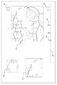
<キーフレームの選択:フレーム画像一覧画面>
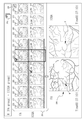
ポインティングデバイス等によって、ボタン265が選択された場合、図3に示す確認画面は、図4に示すフレーム画像の一覧画面に切り替えられる。図4の画面では、撮影画像群に含まれるフレーム画像を、図3の画面と比べて、より多数閲覧するために利用される。そして、閲覧したフレーム画像の中から、所望の造影状態を示す画像を、キーフレームとして選択するためにも利用される。
<Select keyframe: Frame image list screen>
When the
図4の画面においても、図3と同様、サムネイル表示領域210、スライダ220、詳細表示領域230、コントロール255、ボタン260、チェックボックス215等が配置される。特に断りがない限り、図4において、図3と同じ符号が付された箇所は、図3における説明と同様の用途・機能を持つものであるので、詳細な説明は省略する。
Similar to FIG. 3, on the screen of FIG. 4,
図4の画面におけるサムネイル表示領域210には、一連の蛍光造影撮影によって撮影された複数フレームの蛍光造影画像のうち、フレーム画像のみが、選択的に表示される。フレーム画像は、サムネイル211として、サムネイル表示領域210に、時系列に並べられて配置される。
In the
図4の画面において、サムネイル表示領域210には、所定時間間隔(但し、この間隔は、連続造影撮影における撮影フレーム周期よりも大きい)で抽出されたフレーム画像(のサムネイル211)が時系列に並べられてもよい。
In the screen of FIG. 4, in the
この場合、サムネイル表示領域210に並べられるフレーム画像の抽出間隔は、変更可能であってもよい。例えば、抽出間隔の選択操作に基づいて、抽出間隔が変更されたフレーム画像が、サムネイル表示領域210に並べられてもよい。図4の画面では、コントロール(操作部)280にカーソルを合わせて、クリックまたはタップがされることで、予め定められた抽出間隔の選択肢が表示される。選択肢のいずれかが操作部75を介した選択操作に基づいて選択されることにより、選択された抽出間隔で抽出されたフレーム画像が、サムネイル表示領域210に表示される。抽出間隔は、少なくとも、1秒間隔〜10秒間隔までの数秒間隔が選択可能であることが好ましい。造影初期には、数秒間程度示される造影状態を観察することが重要となりうるので、数秒程度の間隔でフレーム画像が並べられている場合、所望の造影状態を示すフレーム画像を、検者が探しやすい。もちろん、選択可能な抽出間隔は、1秒未満であってもよいし、10秒よりも長くてもよい。
In this case, the extraction interval of the frame images arranged in the
図4では、コントロール280の近傍に設けられたチェックボックス281をチェックしておくことで(つまり、空欄状態のチェックボックス281にカーソルをあわせてクリックまたはタップしておくことで)、上記のように、フレーム画像の抽出表示(間引き表示)が行われる。一方、チェックボックス281が空欄であれば、すべてのフレーム画像が時系列に並べられて、サムネイル表示領域210に表示される。例えば、抽出表示を用いてラフに所望の造影状態を示す造影時間を把握してから、すべてのフレーム画像が並べられる状態に変更することで、好適なキーフレームを、速やかに選択することができる。
In FIG. 4, by checking the
抽出表示が行われる場合において、所定時間間隔で抽出されたフレーム画像に加え、連続造影撮影中のトリガ操作に基づいてキーフレームの候補として選択されたフレーム画像が、サムネイル表示領域210に並べられてもよい。この場合、トリガ操作に基づいて得られたフレーム画像と、他のフレーム画像とを、チェックボックス215における感嘆符の有無で、検者は識別することができる。その結果、トリガ操作に基づいて得られたフレーム画像を目安にして、所望の造影状態を示すフレーム画像を、キーフレームとして選択することが可能となる。
When the extraction display is performed, in addition to the frame images extracted at predetermined time intervals, the frame images selected as key frame candidates based on the trigger operation during continuous contrast imaging are arranged in the
図4の画面において、ボタン285が選択されることで、図3の画面に切り替えられる。
By selecting the
なお、図3または図4の確認画面における詳細表示領域230において、撮影画像群に含まれるフレーム画像が表示される場合、その撮影画像群に含まれるフレーム画像が撮影順に切換表示され、その切換表示中に操作部75を介してトリガ操作が行われることで、トリガ操作が行われたタイミング(トリガ信号の出力タイミング)で詳細表示領域230に表示されるフレーム画像が、キーフレームとして選択されてもよい。
When a frame image included in the captured image group is displayed in the
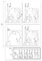
<同時確認画面>
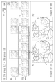
1日の間に、被検眼に対して2種類以上の蛍光造影撮影が行われ、その撮影結果をコンピュータ1が取得している場合、図3の確認画面に代えて、図5に示す確認画面が表示されてもよい。図5の画面では、FAによって得られた蛍光造影画像とICGAによって得られた蛍光造影画像とが、サムネイル表示領域210においてそれぞれ一覧表示される。サムネイル表示領域210には、FAによって得られた蛍光造影画像のサムネイル311と、ICGAによって得られた蛍光造影画像のサムネイル312とが、1列ずつ、上下に並列表示される。サムネイル311と、サムネイル312とは、造影時間によって、対応付けて並べられてもよい。例えば、図5の画面の場合、造影時期が同じサムネイル同士は、上下に隣り合うように配置される。
<Simultaneous confirmation screen>
When two or more types of fluorescence contrast imaging are performed on the eye to be inspected during one day and the imaging result is acquired by the
図5の画面においても、図3と同様、サムネイル表示領域210、スライダ220、詳細表示領域230、コントロール255、ボタン260、チェックボックス215等が配置される。特に断りがない限り、図5において、図3と同じ符号が付された箇所は、図3における説明と同様の用途・機能を持つものであるので、詳細な説明は省略する。
Similar to FIG. 3, on the screen of FIG. 5,
図5における詳細表示領域230では、FA、ICGA2種類の蛍光造影画像の詳細表示が、同時に行われる。詳細表示領域230には、FA用の表示領域230aと、ICGA用の表示領域230bとが設定される。よって、FA,ICGAのそれぞれで得られた蛍光造影画像を、良好に確認することができる。
In the
ここで、ボタン290が選択される度に、同時リンク設定のオン/オフが切り替えられる。同時リンク設定がオフされている場合、FA,ICGAのそれぞれのサムネイル311,312から、詳細表示の対象するものを、個別に選択できる。一方、同時リンク設定がオンされている場合、FA,ICGAのそれぞれのサムネイル311,312のうち、いずれか1つが詳細表示の対象として選択されると、選択されたサムネイルとは異なる蛍光造影撮影に関するサムネイルの中から、造影開始からの経過時間が選択されたサムネイルと同じものが、自動的に、詳細表示の対象として選択される。これにより、詳細表示を行う際の検者の操作負担が軽減される。
Here, each time the
なお、造影撮影の種別ごとに、観察・診断において有用な蛍光造影画像が得られるタイミングは異なるので、図5の画面では、蛍光造影撮影毎に、独立にキーフレームを選択することができる。 Since the timing for obtaining a fluorescence contrast image useful for observation / diagnosis differs depending on the type of contrast imaging, the key frame can be independently selected for each fluorescence imaging on the screen of FIG.
なお、詳細表示領域230に表示されるFA,ICGAの一方の蛍光造影画像において、注目部位の強調表示が行われている場合に、一方の注目部位と同じ部位を、他方の蛍光造影画像においても注目部位として、自動的に強調表示が行われてもよい。例えば、 [強調の再現]の項目で説明した方法と同様、一方の蛍光造影画像と同時に撮影された反射画像、および、他方の蛍光造影画像と同時に撮影された反射画像の位置合わせ結果に基づいて、一方の蛍光造影画像における注目部位と同じ部位が、他方の蛍光造影画像において特定されてもよい。
When the highlighting of the region of interest is performed in one of the FA and ICGA fluorescence contrast images displayed in the
<確認画面の変容例>
[第1変容例]
図6を用いて、第1変容例として、フォローアップのキーフレーム選択に適した確認画面を例示する。前提として、メモリ71に、第1の蛍光造影撮影(ベースライン)に関する画像群データ(ベースラインの画像群データ)、および、キーフレーム特定データが、予めメモリ71に記憶されている。更に、ベースラインの画像群と、造影種別が同じであり、且つ、撮影日が異なる(主には、撮影日が遅い)第2の蛍光造影撮影に関する画像群データ(フォローアップの画像群データ)が、予め取得されている。
<Example of transformation of confirmation screen>
[First transformation example]
With reference to FIG. 6, as a first transformation example, a confirmation screen suitable for follow-up keyframe selection is illustrated. As a premise, the image group data (baseline image group data) related to the first fluorescence contrast imaging (baseline) and the keyframe specific data are stored in the
この場合において、フォローアップの確認画面(キーフレームの選択画面)に、ベースラインのキーフレームが、表示されてもよい。この表示は、例えば、ベースラインの画像群データおよびキーフレーム特定データに基づく。これにより、キーフレームとの比較に適した画像を、フォローアップのキーフレームとして選択することが、容易となる。 In this case, the baseline keyframe may be displayed on the follow-up confirmation screen (keyframe selection screen). This display is based, for example, on baseline image group data and keyframe specific data. This makes it easier to select an image suitable for comparison with the keyframe as the follow-up keyframe.
図6の確認画面では、ベースラインのキーフレームが、(サムネイル表示領域410に、サムネイルとして、)時系列に並べられて表示される。また、ベースラインのキーフレームとして選択可能なフォローアップの蛍光造影画像が、(サムネイル表示領域420に、サムネイルとして、)ベースラインのキーフレームと並列して表示される。
On the confirmation screen of FIG. 6, baseline keyframes are displayed arranged in chronological order (in the
この場合において、ベースラインのキーフレームに対し、フォローアップの蛍光造影画像は、造影時期毎に互いに対応付けて配置されてもよい。つまり、造影時期が同じサムネイル同士が、並列して配置されるように、各々の画像の配置が制御されてもよい。 In this case, the follow-up fluorescence contrast images may be arranged in association with each other for each contrast period with respect to the baseline key frame. That is, the arrangement of each image may be controlled so that thumbnails having the same contrast time are arranged in parallel.
[第2変容例]
確認画面において、詳細表示領域230が予め定められた位置に設定されている必要は無い。例えば、詳細表示領域230を設けずに、確認画面上で、サムネイル211,212を並べ、いずれかのサムネイル211,212が選択された場合に、選択されたサムネイルから切り替えられて、大きなサイズおよび高い画素数の蛍光造影画像であって、選択されたサムネイルと対応する画像が表示されてもよい。
[Second transformation example]
On the confirmation screen, the
[第3変容例]
図7は、図3の確認画面の変容例の1つである。図3のように、サムネイルと、詳細表示領域220における拡大画像とによって、それぞれの蛍光造影画像を、2重に表示するのではなく、サムネネイルと拡大画像との中間程度の大きさの画像を用いて、一覧表示が行われてもよい。
[Third transformation example]
FIG. 7 is one of the transformation examples of the confirmation screen of FIG. As shown in FIG. 3, by using the thumbnail and the enlarged image in the
[第4変容例]
また、確認画面において、サムネイル211,212が表示される必要は、必ずしもない。図8に示す確認画面の第3変容例では、画像表示領域510と、コントロール520と、をから少なくとも構成されていてもよい。コントロール520によって、造影時期が選択され、選択された造影時期と対応する1枚の蛍光造影画像が、画像群データから、選択されて、画像表示領域510に表示される。
[Fourth transformation example]
Further, it is not always necessary to display
図8の例において、コントロール520は、スライダであり、キーフレームとして予め選択された画像の造影時期を示すインデックス522が、スライダ上に表示される。キーフレーム登録ボタン523が操作されることで、その時に画像表示領域510に表示される蛍光造影画像が、キーフレームとして選択されると共に、そのときのスライダのレバー511の位置に、インデックス522が追加的に生成され、表示される。
In the example of FIG. 8, the
なお、拡大表示領域530は、画像表示領域510に表示される蛍光造影画像における注目部位を、画像表示領域510よりも高倍率で表示するための領域である。拡大表示領域530で表示される部位が、画像表示領域510上においてマーカZを用いて強調される。また、観察画像表示領域540には、画像表示領域510に表示される蛍光造影画像と、同時に撮影された反射画像が表示される。
The
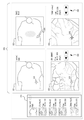
<サマリー編集画面>
図9に示すサマリー編集画面は、蛍光造影撮影に関するサマリーを作成するために利用される。ここでいう、サマリーは、少なくとも眼底画像と、その眼底画像に関する情報とを含み、眼底疾患等の観察・診断に利用されるものである。
<Summary edit screen>
The summary editing screen shown in FIG. 9 is used to create a summary regarding fluorescence contrast imaging. The summary referred to here includes at least a fundus image and information on the fundus image, and is used for observing / diagnosing a fundus disease or the like.
本実施形態では、少なくとも蛍光造影画像が1枚以上含まれるサマリーが、サマリー編集画面を通じて作成される。 In the present embodiment, a summary including at least one fluorescence contrast image is created through the summary editing screen.
本実施形態において、サマリー編集画面は、選択ボックス310(本実施形態における選択領域)と、レイアウト領域320(本実施形態におけるサマリー編集領域)と、に大別される。選択ボックス310は、レイアウト領域320に配置可能な眼底画像がリストアップされている。選択ボックス310内の眼底画像のうち、少なくとも1枚以上を、サマリーにおいて示される画像として、操作部75を介して選択可能である。
In the present embodiment, the summary editing screen is roughly divided into a selection box 310 (selection area in the present embodiment) and a layout area 320 (summary editing area in the present embodiment). The
レイアウト領域320において、サマリーが作成される。作成されたサマリーは、サマリーファイルとしてメモリ71に保存される。保存されたサマリーファイルが読み出された場合、レイアウト領域320(サマリー編集領域)の内容が、サマリーとして再生される。また、作成されたサマリーが印刷される場合、レイアウト領域320の内容が、プリントアウトされる。サマリーが再生またはプリントアウトされる場合は、レイアウト領域320の内容のみが出力さればよく、選択ボックス310が出力される必要は無い。
A summary is created in the
速やかにサマリーを作成するために、サマリー編集画面には、一連の蛍光造影撮影で得られた複数の蛍光造影画像の中でも、観察・診断に有用な造影状態を示す画像のみが配置されることが望まれる。そこで、本実施形態では、蛍光造影画像に関しては、キーフレームとして予め選択された画像が、選択ボックス310において、リストアップされる。
In order to quickly create a summary, among a plurality of fluorescence contrast images obtained by a series of fluorescence contrast imaging, only an image showing a contrast state useful for observation / diagnosis may be arranged on the summary edit screen. desired. Therefore, in the present embodiment, with respect to the fluorescence contrast image, an image selected in advance as a key frame is listed in the
この他、選択ボックス310には、他の眼底正面画像がリストアップされてもよい。例えば、被検眼の反射画像、および、自発蛍光画像の少なくともいずれかが、上記のキーフレームと共に、リストアップされていてもよい。反射画像および自活蛍光画像は、いずれも、被検眼に対する単発的な撮影で撮影された静止画像であってもよい。
In addition, other frontal fundus images may be listed in the
図9における選択ボックス310には、各々の眼底正面画像のサムネイルと、サムネイルとして表示された眼底正面画像に関する情報と、が対応付けて並べられている。眼底正面画像に関する情報としては、撮影方法に関する情報が少なくとも含まれる。蛍光造影画像の場合、造影種別を(例えば、FA,ICGA等)を示す識別情報が、撮影方法に関する情報として含まれる。また、カラー撮影、赤外撮影、単色可視光による撮影、自発蛍光撮影等で得られた眼底正面画像に対しては、その撮影方法を示す情報が、撮影方法に関する情報として示されてもよい。また、併せて、眼底に投影された光の波長域を示す情報が、撮影方法に関する情報として示されてもよい。
In the
また、眼底正面画像に関する情報としては、撮影日時を示す情報が含まれてもよい。また、蛍光造影画像のサムネイルの場合、造影時期を示す時間情報が、更に含まれていてもよい。 Further, the information regarding the frontal image of the fundus may include information indicating the shooting date and time. Further, in the case of a thumbnail of a fluorescence contrast image, time information indicating the contrast time may be further included.
本実施形態において、サムネイルとして表示された眼底正面画像に関する情報は、サムネイル311の近傍に常時表示される。但し、サムネイル311と眼底正面画像に関する情報とが対応付けて表示されればよく、例えば、サムネイル311にカーソルがあったときにだけ、サムネイル311によって示される眼底正面画像に関する情報が一時的に表示される態様であってもよい。なお、一時表示と比べて、常時表示の方が、より速やかに所望の画像を選択しやすいものと考えられる。
In the present embodiment, the information regarding the frontal fundus image displayed as a thumbnail is always displayed in the vicinity of the
レイアウト領域320には、位置および大きさが予め定められたサブ領域が設けられている。図9では、1つのレイアウト領域320内に、4つのサブ領域321〜324が設けられている。図9の例において、レイアウト領域320の大半は、サブ領域321〜324によって、均等に分割される。
The
各々のサブ領域321〜324には、眼底正面画像が配置される領域(画像配置領域)と、その眼底正面画像に関する情報が表示される領域(関連情報表示領域)と、が含まれる。図9に示すように、各々のサブ領域321〜324において眼底正面画像が配置される領域の大きさは均等であってもよい。
Each
レイアウト領域320には、少なくとも3枚分のサブ領域が確保されていてもよい(図9参照)。そして、その3枚分の領域に、被検眼の反射画像と、一連の蛍光造影撮影において、造影初期に撮影された蛍光造影画像、および、造影中期または後期に撮影された蛍光造影画像、がそれぞれ配置可能であってもよい。更に好ましくは、造影中期に撮影された蛍光造影画像と、造影後期に撮影された蛍光造影画像とを別々の領域に表示できるように、4枚分のサブ領域が確保されていてもよい。 At least three sub-areas may be secured in the layout area 320 (see FIG. 9). Then, in the three areas, a reflection image of the eye to be inspected, a fluorescence contrast image taken in the early stage of contrast in a series of fluorescence contrast imaging, and a fluorescence contrast image taken in the middle or late stage of contrast, respectively. It may be arrangeable. More preferably, four sub-regions may be secured so that the fluorescence contrast image taken in the middle stage of contrast and the fluorescence contrast image taken in the latter stage of contrast can be displayed in separate regions.
また、サブ領域の数は、操作部75に対する操作に基づいて、適宜変更可能であってもよい。但し、本実施形態では、サブ領域の数が増減したとしても、少なくとも各々の第1領域のサイズ(保存時、又は、印刷時のサイズ)は一定に維持される。サマリー毎に、画像サイズが一定であれば、サマリー間の比較を良好に行うことができる。なお、サブ領域の数が増えたことにより、すべてのサブ領域を1枚に収めて印刷できない場合は、倍率を変えずに、複数フレームに分割して印刷することが好ましい。
Further, the number of sub-regions may be appropriately changed based on the operation on the
レイアウト領域320では、選択ボックス310を介して選択された眼底正面画像が、サムネイルと比べて大きなサイズで表示される。サブ領域321〜324のそれぞれにおける画像配置領域に、眼底正面画像のうちいずれかがそれぞれ配置され、表示される。また、併せて、サブ領域321〜324のそれぞれにおける関連情報表示領域に、それぞれの画像配置領域に配置された眼底正面画像に関する情報が配置され、表示される。第1領域に蛍光造影画像が配置される場合、その蛍光造影画像の上または近傍に、蛍光造影画像の造影種別、および、造影時期を示す情報のうち少なくともいずれかが配置等される。このような情報が配置されることで、観察・診断を良好に行うことができる。
In the
サブ領域321〜324に対する眼底正面画像の配置操作は、例えば、選択ボックス310内のサムネイル311を各々のサブ領域にドロップする手法であってもよいし、他の手法であってもよい。
The operation of arranging the fundus front image with respect to the
上述した眼底正面画像に関する情報として配置される。これにより、観察・診断を良好に行うことができる。 It is arranged as information regarding the above-mentioned frontal image of the fundus. As a result, observation / diagnosis can be performed satisfactorily.
[カーソルリンク]
サブ領域に表示される各々の眼底正面画像は、それぞれ位置合わせして表示される。位置合わせは、蛍光造影画像、或いは、自発蛍光画像の位置合わせは、蛍光造影画像と同時に撮影された反射画像に基づく。例えば、ポインティングデバイスのカーソル(ポインタ)が配置されているサブ領域の眼底正面画像に対して、他のサブ領域の眼底正面画像を位置合わせしてもよい。また、位置合わせの基準とする画像は、撮影日時、撮影方法、等の眼底正面画像に関する情報に基づいて決定されてもよい。例えば、反射画像がいずれかのサブ領域に表示される場合は、反射画像を基準として、位置合わせが行われてもよい。つまり、この場合、反射画像に対する位置ずれが、その他の画像について求められ、位置合わせが行われる。
[Cursor link]
Each frontal fundus image displayed in the sub-region is displayed in alignment. The alignment is based on the fluorescence contrast image, or the alignment of the spontaneous fluorescence image is based on the reflection image taken at the same time as the fluorescence contrast image. For example, the fundus anterior image of another sub-region may be aligned with the fundus anterior image of the sub-region in which the cursor (pointer) of the pointing device is arranged. Further, the image to be used as the reference for alignment may be determined based on information on the frontal image of the fundus such as the shooting date and time, the shooting method, and the like. For example, when the reflected image is displayed in any of the sub-regions, the alignment may be performed with reference to the reflected image. That is, in this case, the positional deviation with respect to the reflected image is obtained for the other images, and the alignment is performed.
本実施形態では、ポインティングデバイスの操作に応じて移動するカーソルが、あるサブ領域の眼底正面画像上に配置される場合、そのカーソルと同じ位置を示す対応カーソルが、他のサブ領域の眼底正面画像上に配置されてもよい。これにより、検者の注目箇所の観察・診断が行いやすくなる。
<マルチ表示>
また、図10に示すように、レイアウト領域320には、被検眼の反射画像と、第1の造影種別の蛍光造影画像(第1蛍光造影画像)と、第2の造影種別の蛍光造影画像(第2蛍光造影画像)と、の少なくとも3枚が、同時に表示可能であってもよい。好ましくは、更に、自発蛍光画像が同時に表示可能であってもよい。この場合、第1蛍光造影画像および第2蛍光造影画像が配置されるサブ領域に対応付けて、切換コントロール(操作部)340(図10では、切換ボタン)が配置される。切換コントロール340が操作されることによって、第1蛍光造影画像および第2蛍光造影画像は、それぞれと同一撮影日または同一の蛍光造影撮影で得られた同一造影種別の他の画像に切り替えて表示される。本実施形態では、ワンアクションの切換操作で、表示されている画像と造影経過時間が最も近い前後の画像のうちいずれに切り替えられる。ここでは、他のキーフレームの中から、新たに表示される画像が選択される。これにより、造影種別ごとに所望の造影状態を表示させて、見比べることができる。
<フォローアップ表示>
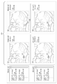
また、図11に示すように、レイアウト領域320には、造影種別が互いに同じ複数の蛍光造影画像であって、撮影日が互いに異なる蛍光造影画像が、同時に表示可能であってもよい。図11の例では、レイアウト作成領域320の上半分のサブ領域321,322にベースラインとなるFAによる蛍光造影画像が表示され、下半分のサブ領域323,324に、ベースラインの後日に撮影されたFAによる蛍光造影画像が表示される。
In the present embodiment, when a cursor that moves according to the operation of the pointing device is placed on the fundus front image of a certain sub-region, the corresponding cursor indicating the same position as the cursor is the fundus front image of another sub-region. It may be placed on top. This makes it easier for the examiner to observe and diagnose the area of interest.
<Multi-display>
Further, as shown in FIG. 10, in the
<Follow-up display>
Further, as shown in FIG. 11, in the
このように、図11では、第1方向に並べられた複数のサブ領域からなる列が、第1方向と交差する方向に並列されており、1つの列のサブ領域に、ベースラインの蛍光造影画像が、他の列のサブ領域に、ベースラインと造影種別が同じであって、ベースラインとは異なる撮影日に撮影された、蛍光造影画像(フォローアップの蛍光造影画像)が、それぞれ配置されるよう、ベースラインの蛍光造影画像と、フォローアップの蛍光造影画像との配置が制限される。また、図11に示すように、ベースラインと、フォローアップ画像とは、それぞれ異なる選択ボックスから選択されてもよい。 As described above, in FIG. 11, a row consisting of a plurality of sub-regions arranged in the first direction is arranged in parallel in a direction intersecting the first direction, and a baseline fluorescence imaging is performed in the sub-region of one row. Fluorescence contrast images (follow-up fluorescence contrast images) in which the images are taken in a sub-region of another row and have the same contrast type as the baseline and are taken on a different shooting date from the baseline are arranged respectively. As such, the placement of the baseline fluorescence image and the follow-up fluorescence image is restricted. Further, as shown in FIG. 11, the baseline and the follow-up image may be selected from different selection boxes.
上一列のサブ領域321,322の1つにベースラインとなる蛍光造影画像が配置された場合、その蛍光造影画像と同じ造影時期を示すフォローアップ画像を、下一列のサブ領域323,324のうち、ベースラインが配置されたサブ領域と隣接するサブ領域に、自動配置されてもよい。つまり、サブ領域321とサブ領域323、サブ領域322とサブ領域324とに、それぞれ造影時期が同じベースライン画像とフォローアップ画像が配置される。また、自動配置に限らず、サブ領域321,322の一方に配置されたベースラインと同じ造影時期を示す画像が、選択ボックス310において、上記一方と隣接するサブ領域に配置可能な画像として示されてもよい。
When a baseline fluorescence contrast image is placed in one of the upper row of
なお、図9〜図11の表示、およびサマリー画面の表示において、各々の蛍光造影画像は、予めメモリ71に記憶されている、造影静止画像のデータ、および、撮影画像群のデータと、キーフレーム特定情報とに基づいて表示されてもよい。
In the display of FIGS. 9 to 11 and the display of the summary screen, each fluorescence contrast image is stored in the
以上、実施形態に基づいて説明を行ったが、本開示は、上記実施形態に限定されるものではなく、上記実施形態に対して、種々の変形を行うことが許容される。 Although the description has been made based on the above-described embodiment, the present disclosure is not limited to the above-described embodiment, and various modifications can be made to the above-described embodiment.
例えば、一連の蛍光造影撮影における単発的な撮影は、連続造影撮影とは、異なる画角で撮影されたり、固視位置の異なる画像として撮影されたり、ステレオ撮影(視差のある複数の画像)として撮影されたりする場合が考えられる。このような単発的な撮影によって得られた造影静止画像が取得された場合、コンピュータ1は、これらの画像を、キーフレームの選択対象から除外してもよい。例えば、確認画面における表示対象から除外してもよい。また、単発的な撮影において、連続造影撮影で得られるフレーム画像の撮影範囲を含み、フレーム画像よりも画角の大きな画像が、造影静止画像として得られる場合、この画像については、キーフレームの選択対象であってもよい。例えば、画角の大きな造影静止画像から、フレーム画像の撮影範囲を抽出し、抽出した画像を、キーフレームの選択画面において表示可能としてもよい。
For example, single-shot imaging in a series of fluorescence contrast imaging may be performed at a different angle of view from continuous contrast imaging, as images with different fixation positions, or as stereo imaging (multiple images with parallax). It may be photographed. When the contrast-enhanced still images obtained by such a single shooting are acquired, the
また、本開示は、蛍光造影撮影に限らず、一連の撮影で、複数回の撮影トリガ信号が出力され、その結果として、多数取得される被検眼の撮影画像から、所望の画像を抽出する場合に適用可能である。例えば、適用可能な被検眼の画像としては、OCT画像、機能OCT画像、眼底画像、前眼部画像等、多岐にわたる。これらの画像は、細胞レベルの画像であってもよく、例えば、細胞レベルで撮影された被検眼画像(例えば、網膜細胞画像)における動態を把握するために、経時的に撮影された細胞レベルの画像の中から、所望の画像を抽出するために利用されてもよい。また、薬剤を投与し、それに対する被検眼における経時的な反応を評価する際に、利用されてもよい。 Further, the present disclosure is not limited to fluorescence contrast imaging, but is a case where a desired image is extracted from a large number of captured images of the eye to be inspected as a result of outputting multiple imaging trigger signals in a series of imaging. Applicable to. For example, the applicable image of the eye to be inspected includes a wide variety of images such as an OCT image, a functional OCT image, a fundus image, and an anterior segment image. These images may be cell-level images, eg, cell-level images taken over time to capture dynamics in a test eye image (eg, retinal cell image) taken at the cell level. It may be used to extract a desired image from the image. It may also be used to administer a drug and evaluate its response over time in the eye to be examined.
1 コンピュータ
70 制御部
71 メモリ
75 操作部
80 モニタ
100 眼底撮影装置
220 スライダ
1
Claims (1)
コンピュータのプロセッサによって実行されることにより、
複数の第1蛍光造影画像と、前記第1蛍光造影画像とは造影種別、造影時期、および、撮影日のいずれかが異なる複数の第2蛍光造影画像と、を複数の前記第1蛍光造影画像と複数の前記第2蛍光造影画像との少なくとも一方に連続撮影による複数のフレーム画像からなる画像群と、撮影トリガ毎の単発的な撮影による造影静止画像と、が混在した状態で取得する取得ステップと、
前記画像群を構成する複数のフレーム画像と前記造影静止画像とのうちいずれかを、複数の前記第1蛍光造影画像と複数の前記第2蛍光造影画像との少なくとも一方のキーフレームとして設定するキーフレーム設定ステップと、
被検眼の観察または診断のためのサマリーとして編集されるサマリー編集領域であって、位置およびサイズが予め定められており各々に1枚ずつ画像が配置される複数のサブ領域を含む、サマリー編集領域を表示部に表示させると共に、
予め設定された前記キーフレームを選択対象として、前記第1蛍光造影画像および前記第2蛍光造影画像の少なくともいずれかを選択する操作を受け付け可能であり、前記操作に基づいて選択されたそれぞれの画像が、前記複数のサブ領域に並べて配置されるサマリー編集ステップと、
前記サマリー編集ステップで編集されたサマリーを、前記表示部上に再生またはプリントアウトするサマリー出力ステップと、を含む眼底画像観察プログラム。 It is a fundus image observation program that at least displays a fluorescence contrast image, which is a frontal image of the fundus by fluorescence taken by a fundus photography device.
By being executed by the computer's processor
A plurality of the first fluorescence contrast images and a plurality of second fluorescence contrast images having different contrast types, contrast timings, and shooting dates from the first fluorescence contrast images. And the acquisition step of acquiring at least one of the plurality of second fluorescence contrast images in a state in which an image group consisting of a plurality of frame images by continuous shooting and a contrast still image by single shooting for each shooting trigger are mixed. When,
A key for setting any one of a plurality of frame images constituting the image group and the contrast-enhanced still image as at least one key frame of the plurality of the first fluorescence contrast images and the plurality of the second fluorescence contrast images. Frame setting steps and
A summary editing area that is edited as a summary for observing or diagnosing the eye to be inspected, including a plurality of sub-areas that are predetermined in position and size and in which one image is placed. Is displayed on the display, and
It is possible to accept an operation of selecting at least one of the first fluorescence contrast image and the second fluorescence contrast image with the preset keyframe as the selection target, and each image selected based on the operation. Is a summary editing step that is arranged side by side in the plurality of sub-areas.
A fundus image observation program including a summary output step of reproducing or printing out a summary edited in the summary editing step on the display unit.
Priority Applications (2)
| Application Number | Priority Date | Filing Date | Title |
|---|---|---|---|
| JP2016194513A JP6957852B2 (en) | 2016-09-30 | 2016-09-30 | Fundus image observation program |
| EP17194187.5A EP3300654B1 (en) | 2016-09-30 | 2017-09-29 | Method for fundus image observation |
Applications Claiming Priority (1)
| Application Number | Priority Date | Filing Date | Title |
|---|---|---|---|
| JP2016194513A JP6957852B2 (en) | 2016-09-30 | 2016-09-30 | Fundus image observation program |
Publications (3)
| Publication Number | Publication Date |
|---|---|
| JP2018051245A JP2018051245A (en) | 2018-04-05 |
| JP2018051245A5 JP2018051245A5 (en) | 2019-09-26 |
| JP6957852B2 true JP6957852B2 (en) | 2021-11-02 |
Family
ID=61834508
Family Applications (1)
| Application Number | Title | Priority Date | Filing Date |
|---|---|---|---|
| JP2016194513A Active JP6957852B2 (en) | 2016-09-30 | 2016-09-30 | Fundus image observation program |
Country Status (1)
| Country | Link |
|---|---|
| JP (1) | JP6957852B2 (en) |
Families Citing this family (2)
| Publication number | Priority date | Publication date | Assignee | Title |
|---|---|---|---|---|
| WO2019203312A1 (en) * | 2018-04-18 | 2019-10-24 | 株式会社ニコン | Image processing method, program, and image processing device |
| JP7421063B2 (en) | 2019-09-04 | 2024-01-24 | 株式会社ニデック | Ophthalmology image observation program |
Family Cites Families (6)
| Publication number | Priority date | Publication date | Assignee | Title |
|---|---|---|---|---|
| JP4307170B2 (en) * | 2003-07-11 | 2009-08-05 | キヤノン株式会社 | Ophthalmic image generation system |
| JP2005103030A (en) * | 2003-09-30 | 2005-04-21 | Seventh Dimension Design:Kk | Apparatus and program for medical image generation |
| JP2008035944A (en) * | 2006-08-02 | 2008-02-21 | Topcon Corp | System for ophthalmologic imaging |
| WO2010135820A1 (en) * | 2009-05-28 | 2010-12-02 | Annidis Health Systems Corp. | Method and system for retinal health management |
| KR101644466B1 (en) * | 2012-08-30 | 2016-08-01 | 캐논 가부시끼가이샤 | Information processing apparatus and method |
| JP6417807B2 (en) * | 2014-09-12 | 2018-11-07 | 株式会社ニデック | Ophthalmic image processing device |
-
2016
- 2016-09-30 JP JP2016194513A patent/JP6957852B2/en active Active
Also Published As
| Publication number | Publication date |
|---|---|
| JP2018051245A (en) | 2018-04-05 |
Similar Documents
| Publication | Publication Date | Title |
|---|---|---|
| US10588505B2 (en) | Diagnosis support apparatus and method | |
| US8803964B2 (en) | Imaging apparatus and imaging method, program, and recording medium | |
| US9848772B2 (en) | Image displaying method | |
| US10098542B2 (en) | Fundus observation apparatus | |
| US9782071B2 (en) | Ophthalmologic photographing apparatus and ophthalmologic photographing method | |
| EP3300654B1 (en) | Method for fundus image observation | |
| JP6918525B2 (en) | Ophthalmology medical information processing system and ophthalmic medical information processing method | |
| JP6825292B2 (en) | Fundus image observation program | |
| EP2859838A1 (en) | Ophthalmologic photographing device and ophthalmologic image processing device | |
| JP6957852B2 (en) | Fundus image observation program | |
| US8774489B2 (en) | Ophthalmology information processing apparatus and method of controlling the same | |
| JP6747227B2 (en) | Fundus image observation program | |
| JP2009080545A (en) | Medical information processor | |
| JP6645003B2 (en) | Ophthalmic examination information processing apparatus and ophthalmic examination information processing program | |
| JP7484087B2 (en) | Fundus image observation program | |
| JP2018051245A5 (en) | ||
| JP2022047420A (en) | Ocular fundus image observation program | |
| JP7415570B2 (en) | Ophthalmology imaging device control program, ophthalmology imaging system, and ophthalmology imaging device | |
| US11389055B2 (en) | Ophthalmological image observation method and ophthalmological image observation apparatus | |
| JP2008154951A (en) | Fundus image processing device, ophthalmography device and program |
Legal Events
| Date | Code | Title | Description |
|---|---|---|---|
| A521 | Written amendment |
Free format text: JAPANESE INTERMEDIATE CODE: A523 Effective date: 20190810 |
|
| A621 | Written request for application examination |
Free format text: JAPANESE INTERMEDIATE CODE: A621 Effective date: 20190810 |
|
| A977 | Report on retrieval |
Free format text: JAPANESE INTERMEDIATE CODE: A971007 Effective date: 20200731 |
|
| A131 | Notification of reasons for refusal |
Free format text: JAPANESE INTERMEDIATE CODE: A131 Effective date: 20200811 |
|
| A601 | Written request for extension of time |
Free format text: JAPANESE INTERMEDIATE CODE: A601 Effective date: 20201012 |
|
| A521 | Written amendment |
Free format text: JAPANESE INTERMEDIATE CODE: A523 Effective date: 20201210 |
|
| A131 | Notification of reasons for refusal |
Free format text: JAPANESE INTERMEDIATE CODE: A131 Effective date: 20210202 |
|
| A521 | Written amendment |
Free format text: JAPANESE INTERMEDIATE CODE: A523 Effective date: 20210405 |
|
| A131 | Notification of reasons for refusal |
Free format text: JAPANESE INTERMEDIATE CODE: A131 Effective date: 20210518 |
|
| A521 | Written amendment |
Free format text: JAPANESE INTERMEDIATE CODE: A523 Effective date: 20210719 |
|
| TRDD | Decision of grant or rejection written | ||
| A01 | Written decision to grant a patent or to grant a registration (utility model) |
Free format text: JAPANESE INTERMEDIATE CODE: A01 Effective date: 20210907 |
|
| A61 | First payment of annual fees (during grant procedure) |
Free format text: JAPANESE INTERMEDIATE CODE: A61 Effective date: 20210920 |
|
| R150 | Certificate of patent or registration of utility model |
Ref document number: 6957852 Country of ref document: JP Free format text: JAPANESE INTERMEDIATE CODE: R150 |