JP6955868B2 - Data communication equipment, systems, and methods - Google Patents
Data communication equipment, systems, and methods Download PDFInfo
- Publication number
- JP6955868B2 JP6955868B2 JP2016574099A JP2016574099A JP6955868B2 JP 6955868 B2 JP6955868 B2 JP 6955868B2 JP 2016574099 A JP2016574099 A JP 2016574099A JP 2016574099 A JP2016574099 A JP 2016574099A JP 6955868 B2 JP6955868 B2 JP 6955868B2
- Authority
- JP
- Japan
- Prior art keywords
- housing
- transceiver
- data
- underground
- communication system
- Prior art date
- Legal status (The legal status is an assumption and is not a legal conclusion. Google has not performed a legal analysis and makes no representation as to the accuracy of the status listed.)
- Active
Links
Images


Classifications
-
- H—ELECTRICITY
- H04—ELECTRIC COMMUNICATION TECHNIQUE
- H04L—TRANSMISSION OF DIGITAL INFORMATION, e.g. TELEGRAPHIC COMMUNICATION
- H04L67/00—Network arrangements or protocols for supporting network services or applications
- H04L67/01—Protocols
- H04L67/12—Protocols specially adapted for proprietary or special-purpose networking environments, e.g. medical networks, sensor networks, networks in vehicles or remote metering networks
-
- H—ELECTRICITY
- H04—ELECTRIC COMMUNICATION TECHNIQUE
- H04Q—SELECTING
- H04Q9/00—Arrangements in telecontrol or telemetry systems for selectively calling a substation from a main station, in which substation desired apparatus is selected for applying a control signal thereto or for obtaining measured values therefrom
-
- H—ELECTRICITY
- H04—ELECTRIC COMMUNICATION TECHNIQUE
- H04L—TRANSMISSION OF DIGITAL INFORMATION, e.g. TELEGRAPHIC COMMUNICATION
- H04L63/00—Network architectures or network communication protocols for network security
- H04L63/04—Network architectures or network communication protocols for network security for providing a confidential data exchange among entities communicating through data packet networks
- H04L63/0428—Network architectures or network communication protocols for network security for providing a confidential data exchange among entities communicating through data packet networks wherein the data content is protected, e.g. by encrypting or encapsulating the payload
-
- G—PHYSICS
- G05—CONTROLLING; REGULATING
- G05B—CONTROL OR REGULATING SYSTEMS IN GENERAL; FUNCTIONAL ELEMENTS OF SUCH SYSTEMS; MONITORING OR TESTING ARRANGEMENTS FOR SUCH SYSTEMS OR ELEMENTS
- G05B15/00—Systems controlled by a computer
- G05B15/02—Systems controlled by a computer electric
-
- H—ELECTRICITY
- H04—ELECTRIC COMMUNICATION TECHNIQUE
- H04B—TRANSMISSION
- H04B1/00—Details of transmission systems, not covered by a single one of groups H04B3/00 - H04B13/00; Details of transmission systems not characterised by the medium used for transmission
- H04B1/38—Transceivers, i.e. devices in which transmitter and receiver form a structural unit and in which at least one part is used for functions of transmitting and receiving
- H04B1/40—Circuits
-
- H—ELECTRICITY
- H04—ELECTRIC COMMUNICATION TECHNIQUE
- H04Q—SELECTING
- H04Q2209/00—Arrangements in telecontrol or telemetry systems
- H04Q2209/40—Arrangements in telecontrol or telemetry systems using a wireless architecture
-
- H—ELECTRICITY
- H04—ELECTRIC COMMUNICATION TECHNIQUE
- H04Q—SELECTING
- H04Q2209/00—Arrangements in telecontrol or telemetry systems
- H04Q2209/80—Arrangements in the sub-station, i.e. sensing device
- H04Q2209/88—Providing power supply at the sub-station
Landscapes
- Engineering & Computer Science (AREA)
- Computer Networks & Wireless Communication (AREA)
- Computer Security & Cryptography (AREA)
- General Engineering & Computer Science (AREA)
- Signal Processing (AREA)
- Computing Systems (AREA)
- Computer Hardware Design (AREA)
- General Physics & Mathematics (AREA)
- Physics & Mathematics (AREA)
- Automation & Control Theory (AREA)
- Health & Medical Sciences (AREA)
- General Health & Medical Sciences (AREA)
- Medical Informatics (AREA)
- Arrangements For Transmission Of Measured Signals (AREA)
- Alarm Systems (AREA)
- Selective Calling Equipment (AREA)
Description
マシン間通信は、とりわけ、エネルギー、通信、及びセキュリティ市場に対してますます重要になってきている。当該業界において使用されている監視制御データ収集(SCADA)システムは、遠隔に位置するセンサからの入力に依存して、適切に機能している。SCADAシステムはまた、信号を出力して、現地における遠隔機器を起動することができる。その機器のかなりの部分(米国電気事業者の〜18%)は、地中に位置し、地上機器と地中機器との無線通信を提供することは、重要な課題である。 Machine-to-machine communication is becoming increasingly important, especially for the energy, communications, and security markets. Surveillance and control data collection (SCADA) systems used in the industry rely on inputs from remote sensors to function properly. The SCADA system can also output a signal to activate a remote device in the field. A significant portion of that equipment (~ 18% of US utilities) is located underground, and providing wireless communication between terrestrial and underground equipment is an important challenge.
地中ケーブルの障害の場所を探すために使用される現在の方法は、依然として緩慢であり、労働集約的である。比較的短い供給停止なら、事業者に対して使用されてもよく、顧客に対して速度調整を行うことができるので、地中障害の場所を探し修理するより迅速な手段が必要である。 Current methods used to locate underground cable failures remain slow and labor intensive. Relatively short outages may be used by businesses and speed adjustments can be made to customers, so there is a need for faster means of finding and repairing underground obstacles.
このように、地中機器が位置する地中機器用ボールト及び他の構造体の内外へ無線信号を伝達するニーズがある。 As described above, there is a need to transmit wireless signals to the inside and outside of the underground device vault and other structures in which the underground device is located.
本発明の一態様において、データ通信システムは、地中又は地盤面の筐体などの筐体への入り口ポート上に配設された送受信機を備える。送受信機は、地中筐体環境に対応するよう、入り口ポートに装着可能なハウジングを具備したことで、送受信機が地中筐体の外部のネットワークと通信するように構成されるようになっている。また、データ通信システムは、筐体内に配設された、センサのような監視装置を具備し、筐体内のリアルタイムの状況に関するデータが提供されている。データ通信システムはまた、監視装置/センサからのデータを処理し、処理済みデータ信号を生成して、処理済みデータ信号を送受信機に通信する、センサ解析部も具備する。 In one aspect of the invention, the data communication system comprises a transceiver disposed on an entrance port to a housing such as a housing in the ground or on the ground surface. The transceiver is equipped with a housing that can be attached to the entrance port so as to correspond to the underground housing environment, so that the transceiver is configured to communicate with the network outside the underground housing. There is. Further, the data communication system includes a monitoring device such as a sensor arranged in the housing, and data on the real-time situation in the housing is provided. The data communication system also includes a sensor analysis unit that processes data from the monitoring device / sensor, generates a processed data signal, and communicates the processed data signal to a transmitter / receiver.
別の態様において、センサは、電力、電圧、電流、温度、可燃物質又は燃焼副産物、機械的歪み、機械的移動、湿度、土壌状態、圧力、危険雰囲気、液体フロー、漏れ、部品寿命又は耐用年限、人感、物理的状態、光度、及び振動のうち少なくとも1つを検出する。更なる態様において、センサは、感知型ケーブル付属品に組み込まれ、電力ケーブルの状況を監視するように構成されている。 In another embodiment, the sensor is a power, voltage, current, temperature, flammable material or combustion by-product, mechanical strain, mechanical movement, humidity, soil condition, pressure, dangerous atmosphere, liquid flow, leak, component life or useful life. Detects at least one of human sensation, physical condition, luminosity, and vibration. In a further aspect, the sensor is incorporated into a sensing cable accessory and is configured to monitor the status of the power cable.
更に別の態様において、センサ解析部は、デジタル信号プロセッサを具備する。別の態様において、センサ解析部は、無線ネットワーク通信チップを具備する。 In yet another embodiment, the sensor analysis unit comprises a digital signal processor. In another aspect, the sensor analysis unit comprises a wireless network communication chip.
別の態様において、送受信部は、耐久性を有する地上アンテナ及び無線機を具備する。別の態様において、送受信機は、集約された情報を、地上にある上流の別の集約ノード又はクラウドサーバに送信するように構成されている。更なる態様において、集約されたデータは、定期的な状態通知及び非同期警報通知の1つ又は2つ以上を含む。 In another aspect, the transmitter / receiver comprises a durable terrestrial antenna and radio. In another embodiment, the transceiver is configured to transmit the aggregated information to another upstream aggregate node or cloud server on the ground. In a further aspect, the aggregated data includes one or more of periodic status notifications and asynchronous alarm notifications.
別の態様において、入り口ポートは、マンホールの蓋を含む。更なる態様において、送受信機は、マンホールの蓋に固定され、かつ前記入り口の蓋内に形成された穴を貫いて延在する送受信機ハウジングの一部分にも固定されている。更に別の態様において、前記入り口の蓋内に形成された穴を貫通して延在する前記送受信機ハウジング部分は、入り口の蓋の頂面と実質的に同一平面上にある。 In another embodiment, the entrance port comprises a manhole cover. In a further aspect, the transceiver is fixed to the manhole cover and also to a portion of the transceiver housing that extends through a hole formed in the entrance cover. In yet another embodiment, the transceiver housing portion extending through a hole formed in the entrance lid is substantially coplanar with the top surface of the entrance lid.
別の態様において、前記入り口ポートは、マンホールの蓋と、マンホールの蓋を受容するリング部分と、を備え、前記送受信機が前記入り口ポートの前記リング部分に固定されている。 In another embodiment, the entrance port comprises a manhole cover and a ring portion that receives the manhole cover, and the transceiver is fixed to the ring portion of the entrance port.
別の態様において、データ通信システムは、地中筐体内に位置する少なくとも1つの電力線に連結された電力採取装置(power harvesting device)を更に備える。別の態様では、電力採取装置が前記センサ解析部に連結され、かつ前記センサ解析部に電力を供給する。 In another aspect, the data communication system further comprises a power harvesting device connected to at least one power line located within the underground enclosure. In another aspect, the power sampling device is connected to the sensor analysis unit and supplies power to the sensor analysis unit.
本発明の別の態様において、データ通信システムは、地中筐体への入り口ポート上に配設された送受信機を備える。前記送受信機は、前記入り口ポートに装着可能なハウジングを具備し前記送受信機が前記地中筐体の外部のネットワークと通信するように構成されている。本システムはまた、感知型ケーブル付属品を具備する。この感知型ケーブル付属品は、地中筐体内に位置する電力線に装着され、地中筐体内部のリアルタイム状況に関連するデータを測定するセンサを具備する。前記感知型ケーブル付属品はまた、前記測定されたデータを処理する信号処理チップと、処理済みデータを前記送受信機に通信する通信チップと、を具備する。 In another aspect of the invention, the data communication system comprises a transceiver disposed on an entrance port to an underground enclosure. The transceiver includes a housing that can be attached to the entrance port, and the transceiver is configured to communicate with a network outside the underground housing. The system is also equipped with sensitive cable accessories. This sensing cable accessory is attached to a power line located inside the underground housing and includes a sensor that measures data related to the real-time situation inside the underground housing. The sensing cable accessory also includes a signal processing chip that processes the measured data and a communication chip that communicates the processed data to the transceiver.
別の態様において、前記感知型ケーブル付属品は、前記信号処理チップ及び通信チップに対し電力を供給するために電力線に連結した電力採取装置を更に備える。 In another aspect, the sensing cable accessory further comprises a power extraction device connected to a power line to supply power to the signal processing chip and the communication chip.
本発明の別の態様において、データ通信システムは、ユーティリティ機器を収容する筐体の一部分の上に配設された送受信機を備える。この送受信機は、前記筐体に装着可能なハウジングを含み、前記送受信機は前記筐体の外部のネットワークと通信するように構成されている。また、本システムは、筐体内に配設された、センサのような監視装置を具備し、監視装置は筐体内のリアルタイムの状況に関するデータを提供するようになっている。本システムはまた、監視装置/センサからのデータを処理し、処理済みデータ信号を生成するための、センサ解析部も具備する。前記処理済みデータ信号は、前記送受信機に通信し得る。 In another aspect of the invention, the data communication system comprises a transceiver disposed on a portion of a housing that houses utility equipment. The transceiver includes a housing that can be mounted on the housing, and the transceiver is configured to communicate with a network outside the housing. In addition, this system includes a monitoring device such as a sensor arranged in the housing, and the monitoring device provides data on the real-time situation in the housing. The system also includes a sensor analysis unit for processing data from monitoring devices / sensors and generating processed data signals. The processed data signal may communicate with the transceiver.
別の態様において、前記筐体は、地中ボールトを備える。更なる態様において、前記筐体は、地盤面又は地上の筐体を備える。 In another embodiment, the housing comprises an underground vault. In a further aspect, the housing comprises a ground surface or ground housing.
本発明の上記の概要は、本発明のそれぞれの図示された実施形態又は全ての実施を説明しようとするものではない。下記の図面及び発明を実施するための形態は、これらの実施形態をより具体的に例示する。 The above outline of the present invention is not intended to illustrate each of the illustrated embodiments or all embodiments of the present invention. The following drawings and embodiments for carrying out the invention exemplify these embodiments more specifically.
以下では、一部において、図面を参照しながら本発明の非限定例によって、本発明を説明する。
本発明は様々な修正及び代替形態が可能であるが、その具体像を例として図面に示すと共に詳細に説明する。しかしながら、その意図は、記載された特定の実施形態に本発明を限定することにないことを理解するべきである。逆に、本発明は、添付の請求の範囲に記載した発明の範囲を逸脱することなく、あらゆる変更、均等物、及び代替物を網羅することを意図している。 Various modifications and alternative forms are possible in the present invention, and a concrete image thereof will be shown in the drawings as an example and will be described in detail. However, it should be understood that the intent is not to limit the invention to the particular embodiments described. Conversely, the invention is intended to cover all modifications, equivalents, and alternatives without departing from the scope of the invention described in the appended claims.
以下の発明を実施するための形態では、本明細書の一部を構成する添付の図面を参照し、本発明を実施することができる特定の実施形態を例として示す。その際、「上」、「下」、「前」、「後」、「前縁」、「前方」、「後縁」などの方向に関する用語は、説明する図面の方向を基準として用いられている。本発明の各実施形態の構成要素は多数の様々な方向で位置決めされ得るため、方向に関する用語は、説明の目的で用いられており、限定するものではない。他の実施形態を利用することもでき、また、構造的又は論理的な変更が、本発明の範囲から逸脱することなくなされ得ることが理解される。したがって、以下の詳細な説明は、限定的な意味で解釈されるべきではなく、本発明の範囲は、添付の特許請求の範囲によって定義される。 In the following embodiments for carrying out the present invention, specific embodiments in which the present invention can be carried out are shown as examples with reference to the accompanying drawings constituting a part of the present specification. At that time, terms related to directions such as "upper", "lower", "front", "rear", "leading edge", "front", and "rear edge" are used with reference to the direction of the drawing to be explained. There is. As the components of each embodiment of the invention can be positioned in a number of different directions, directional terms are used for purposes of explanation and are not intended to be limited. Other embodiments may be utilized and it is understood that structural or logical changes can be made without departing from the scope of the invention. Therefore, the following detailed description should not be construed in a limited sense and the scope of the invention is defined by the appended claims.
本明細書には、地面レベル、地上又は地中の筐体のような筐体内で利用できるデータ通信機器、システム、及び方法が記載されている。一態様において、筐体は、入り口ポートを介してアクセス可能な地中筐体である。本データ通信システムは、ボールト又はマンホールのような地中筐体への入り口ポート上に配設された送受信機を具備する。送受信機は、頑丈なハウジングを具備する。いくつかの態様において、頑丈なハウジングの少なくとも一部は、入り口ポートの表面上に延在する。他の態様において、頑丈なハウジングは、入り口ポートに取付けられ、ハウジングの一部分が入り口ポートの頂面と実質的に同一平面上にあり、かつハウジングの実質的な部分が、入り口ポートの頂面の下部に配設されるようになっている。監視装置は、ボールト内に配設される。監視装置は、ボールト内のリアルタイムの状況に関するデータを提供するセンサであってもよい。加えて、いくつかの態様において、データ通信システムは、送受信機にデータを中継するゲートウェイ部を具備し得る。他の態様において、センサ解析部は、監視装置からのリアルタイムデータの処理及び分析を行い、その処理されたデータを送受信機に中継し得る。更なる態様において、センサ及びセンサ解析部は、感知型電子付属品の一部分として組み込むことが可能である。 This specification describes data communication devices, systems, and methods that can be used within a housing at the ground level, such as a housing on the ground or in the ground. In one aspect, the enclosure is an underground enclosure accessible via an entrance port. The data communication system includes a transceiver arranged on an entrance port to an underground housing such as a vault or a manhole. The transceiver is equipped with a sturdy housing. In some embodiments, at least a portion of the sturdy housing extends over the surface of the inlet port. In another embodiment, the rugged housing is attached to the entrance port, a portion of the housing is substantially coplanar with the top surface of the entrance port, and a substantial portion of the housing is on the top surface of the entrance port. It is designed to be arranged at the bottom. The monitoring device is arranged in the vault. The monitoring device may be a sensor that provides data about the real-time situation in the vault. In addition, in some embodiments, the data communication system may include a gateway unit that relays data to the transceiver. In another aspect, the sensor analysis unit may process and analyze real-time data from the monitoring device and relay the processed data to the transceiver. In a further embodiment, the sensor and sensor analyzer can be incorporated as part of a sensing electronic accessory.
特に、或る態様において、送受信機は、物理的に頑強なアンテナ及び無線機を含む。このアンテナ/送受信機は、地中筐体内に配設されたこれらの部品/機器に対する環境、部品、及び他の電子機器の状況に関するリアルタイムのデータを提供する(複数の)監視装置/(複数の)センサからの無線信号及び/又は有線信号の組み合わせを用いることができる。更に、通信システムは、他の場所の地中に配設された他の機器及び部品と通信することができる。いくつかの態様において、ゲートウェイ部は、これらの監視装置/センサ及び地中機器から送受信機へのデータペイロードを中継し、送受信機は、無線アクセスポイント、移動無線セル、及び構内無線などの地上ネットワーク要素と通信することができる。他の態様において、感知型解析部は、センサにより測定されたデータに対応する処理済みデータを、送受信機に中継する。このように、態様によっては、センサを使用して、地中化送電網の性能についてのリアルタイムの情報を提供することができ、これらの監視装置/センサと通信するための費用対効果の高い手段は、無線ネットワークを使用することによるものである。 In particular, in some embodiments, the transceiver includes a physically robust antenna and radio. This antenna / transmitter / receiver provides real-time data on the environment, components, and the status of other electronic devices for these components / devices located within the underground enclosure. ) A combination of wireless and / or wired signals from the sensor can be used. In addition, the communication system can communicate with other devices and components located underground elsewhere. In some embodiments, the gateway relays the data payload from these monitoring devices / sensors and underground equipment to the transceiver, which is a terrestrial network such as a wireless access point, mobile radio cell, and premises radio. Can communicate with the element. In another embodiment, the sensing type analysis unit relays the processed data corresponding to the data measured by the sensor to the transceiver. Thus, in some embodiments, sensors can be used to provide real-time information about the performance of underground grids and are a cost-effective means of communicating with these monitoring devices / sensors. Is due to the use of wireless networks.
送受信機は、嵩上げ型構造体又は面一取付けされた構造体内に、配設又は埋め込むことができる。別の態様では、それぞれ地上送信用及び地下送信用に埋め込まれた嵩上げ型構造体のアンテナ及び/又は電子装置の整合する対が、地中筐体に対して提供され得る。更に、複数のアンテナ(例えば、WiFi、GPS、移動無線機などの信号を送信/受信するアンテナ)が単一の頑強な構造体内に提供される。 The transceiver can be disposed or embedded in a raised structure or a flush-mounted structure. In another aspect, matching pairs of antennas and / or electronics of raised structures embedded for ground and underground transmission, respectively, may be provided for the underground enclosure. In addition, multiple antennas (eg, antennas that transmit / receive signals from WiFi, GPS, mobile radios, etc.) are provided within a single robust structure.
図1に、本発明の一態様であるデータ通信システム100を示す。本態様において、データ通信システム100は、地中データ通信システムである。通信システム100は、例示的な地中筐体(ここでは地中ボールト10)内に配設されている。この例示的な実施において、ボールト10は、(例えば、低、中若しくは高圧電力を搬送する)送電線105a〜105cなどの1つ又は2つ以上の高電圧送電線などの多様な設備、関連する部品及び/又は接合部又は終端部(図1の実施例において、終端部110は、かかる関連する部品及び/又は付属品を表すものとする)などの付属品、降圧変圧器103などの変換器、及び(低圧電力(例えば、440V)を近辺の建物又は構造体へ搬送する)更なる送電線107a〜107cを備える。ボールトによっては、変換器は、ボールト内に備えられなくてもよい。
FIG. 1 shows a
筐体又はボールト10は、金属製又は非金属製であってもよいし従来の円形であってもよい従来のマンホールの蓋50を具備する扉又は入り口ポート55を介して、地上からアクセスできる。一態様において、マンホールの蓋52は、入り口ポート55のリング、フレーム、又はフランジ構造体52上に装着できる。本態様において、ボールト10は、従来の地中ボールトとして構築され、電気、ガス、水、及び/又は他の事業者によって通常使用される。一方、代替の態様において、地中データ通信システム100は、別のタイプの地中筐体で利用することもできるし、又はマンホール、ベースメント、地下室、ピット、シェルタ、管、若しくは他の地中筐体のような同様の構造体内で利用することもできる。
The housing or
ボールトはまた、ボールト内に配設された少なくとも1つの監視装置を具備し、この監視装置で、ボールトの物理的状況、又はボールト内に位置する部品若しくは機器の物理的状況を、監視できる。かかる状況は、通常、地上から収集又は調査することが難しいだろう。以下に詳細に記載されるように、地中データ通信システムは、保守技術員が物理的にボールトに入って、ボールトの状況を判定しなくても、ボールトの状況情報を地上ネットワーク又はSCADAへ中継する通信用インフラストラクチャを提供することができる。 The vault also comprises at least one monitoring device disposed within the vault, which can monitor the physical condition of the vault or the physical condition of a component or device located within the vault. Such situations will usually be difficult to collect or investigate from the ground. As described in detail below, an underground data communication system relays vault status information to a terrestrial network or SCADA without the need for maintenance technicians to physically enter the vault and determine vault status. It can provide communication infrastructure.
更なる態様において、地中通信システムは、地上環境内に実装できる。例えば、地面レベルのパッドが装着された筐体内に、通信システム100を装着できる。通信システムは、構造体から及び構造体へ無線で通信する手段を提供し得る。この手段が提供されない場合、この構造体は、構造体の内部部分からの及びその内部部分への直接的な無線通信が妨げられるように構築される。
In a further aspect, the underground communication system can be implemented in a terrestrial environment. For example, the
図1に示すように、本例において、終端部110は、低、中又は高圧電力ケーブル105a〜105cなどの電力ケーブルの端子接続を提供する。監視装置は、終端部に配設されたセンサであってもよい。本センサは、電圧、電流、及び/又は温度などのケーブル状況を測定する検知能力を提供することができる。このように、本例において、終端部110は、感知型終端部110と称されてもよく、1つ又は2つ以上の接続された電力線の状況に関するリアルタイムのデータを提供することができる。
As shown in FIG. 1, in this example, the
例えば、本態様の感知型終端部110は、電流の微分に比例する電圧を生成するロゴスキー(Rogowski)コイルを備えてもよく、これは、積分器を利用して、電流に比例する信号へ戻すことができることを意味する。代替的に、電流センサは、内部導体上の電流に比例する電流を生成する電磁鉄芯電流変換器として構成されてもよい。更に、感知型終端部110は、正確な電圧測定値を提供する容量性電圧センサを備えてもよい。感知型終端部110は、電流センサと容量性電圧センサとの両方を含んでもよく、感知型終端部により、位相角(電力因子)、ボルトアンペア(VA)、ボルトアンペア無効電力(VAr)、及びワット(W)の算出を容易にすることができる。例示的な感知型終端部は、その全体が参照により本明細書に援用されている、米国特許仮出願第61/839543号に記載されている。
For example, the
図1の実施形態に、感知型端末として実装される監視装置を示す。本発明の他の態様において、監視装置は、ケーブル端末、ケーブル接合部、又は電子ジャンパのようなより一般的な感知型電子付属品の一部分として実装できる。 An embodiment of FIG. 1 shows a monitoring device mounted as a sensing type terminal. In another aspect of the invention, the monitoring device can be implemented as part of a more common sensing electronic accessory such as a cable terminal, cable junction, or electronic jumper.
このように、監視装置は、以下のセンサ:電力センサ、電圧センサ、電流センサ、温度センサ、可燃物質センサ又は燃焼副産物センサ、機械的歪みセンサ、機械的移動(例えば、毎分回転数)センサ、湿度センサ、土壌状態(酸度、含水量、鉱物の含有量)センサ、圧力センサ、危険雰囲気センサ、液体フローセンサ、漏れセンサ、部品寿命センサ又は耐用年限センサ(例えば、陰極防食センサ)、(例えば、筐体に入った人がいるかなどの)人感センサ、(例えば、筐体の開閉、ドアの開閉、スイッチ又はバルブの開閉、不正使用された品目があるかなどの)物理的状態センサ、光センサ、振動(地震、不正使用)センサのうち1つ又は2つ以上を備えてもよいと想到される。 As described above, the monitoring device includes the following sensors: power sensor, voltage sensor, current sensor, temperature sensor, combustible substance sensor or combustion by-product sensor, mechanical strain sensor, mechanical movement (for example, rotation speed per minute) sensor, Humidity sensor, soil condition (acidity, water content, mineral content) sensor, pressure sensor, dangerous atmosphere sensor, liquid flow sensor, leak sensor, component life sensor or service life sensor (eg, cathode corrosion protection sensor), (eg, cathode corrosion protection sensor) Human sensor (for example, whether someone has entered the housing), physical condition sensor (for example, opening / closing the housing, opening / closing the door, opening / closing the switch or valve, whether there is an item that has been misused, etc.), light It is conceivable that one or more of the sensors, vibration (earthquake, unauthorized use) sensors may be provided.
本発明の別の態様において、データは、筐体内部の監視装置から筐体外側に位置するネットワーク又はSCADAへ通信される。この通信は、ゲートウェイ部及び送受信部を介して遂行される。以下に更に詳細に説明されるように、ゲートウェイ部は、遠隔端末装置内に組み込むこともできるし、入り口の扉に装着された送受信装置内に組み込むこともでき、或いは筐体内又は筐体入り口の自立型装置として実装することもできる。 In another aspect of the invention, data is communicated from a monitoring device inside the enclosure to a network or SCADA located outside the enclosure. This communication is carried out via the gateway unit and the transmission / reception unit. As will be described in more detail below, the gateway unit can be incorporated in a remote terminal unit, in a transmitter / receiver mounted on an entrance door, or in a housing or at the entrance of a housing. It can also be mounted as a self-supporting device.
ゲートウェイ部は、有線又は無線接続を使用して地中を多様な監視装置へ接続することができる。ゲートウェイ部は、監視装置からのデータについて、現場での分析及び解釈を行うことができる。例えば、ゲートウェイ部は、監視装置/センサ情報を解釈して、有害ガス、水分、塵埃、化学成分、腐食の有無、害虫の有無などの環境状況を判定する。更に、ゲートウェイ部は、スイッチの開閉など現場での処置を行うことができる。更に、ゲートウェイ部は、定期的な状態通知又は非同期警報通知などの集約された情報を、地上にある上流の別の集約ノード又はクラウドサーバに対して送ることができる。ゲートウェイ部はまた、上流の集約ノード又はクラウド(例えば、SCADA)サービスによってゲートウェイ部に送られたメッセージに応答することができる。上流ノード又はクラウドサービスからの典型的なコマンドとしては、「状態の送信」、「処置の実施」、「設定パラメータの設定」、「ソフトウェアの搭載」などが挙げられる。 The gateway unit can connect the underground to various monitoring devices using a wired or wireless connection. The gateway unit can analyze and interpret the data from the monitoring device in the field. For example, the gateway unit interprets the monitoring device / sensor information to determine environmental conditions such as harmful gas, moisture, dust, chemical components, presence / absence of corrosion, and presence / absence of pests. Further, the gateway unit can perform on-site measures such as opening and closing a switch. Further, the gateway unit can send aggregated information such as periodic status notification or asynchronous alarm notification to another aggregation node or cloud server upstream on the ground. The gateway unit can also respond to messages sent to the gateway unit by upstream aggregate nodes or cloud (eg, SCADA) services. Typical commands from the upstream node or cloud service include "send status", "take action", "set configuration parameters", "install software" and the like.
図1に示すように、本例において、感知型終端部110a〜110cからのデータは、1つ又は2つ以上の通信ケーブル(ここでは、2本のケーブルがそれぞれの感知型終端部に接続されたケーブル130a〜130f)を介して遠隔端末装置、すなわちRTU 120へ通信することができる。RTU 120は、ボールト10内の中心位置に、又は壁若しくは他の内部ボールト構造体に沿って装着されてもよい。本発明の本実施形態において、RTU 120は、(別々に図示されていない)ゲートウェイ部を備えてもよい。代替的に、ゲートウェイ部は、送受信機140内に配設されてもよく、独立型部品として構成されてもよい。ゲートウェイ部及び送受信機は、以下に更に詳細に記載される。
As shown in FIG. 1, in this example, the data from the
一態様では、RTU 120は、感知型終端部110から受信したデータ信号を処理し、かかるデータ信号を監視制御データ収集(SCADA)システム内で使用可能な信号に変換するように適合される。更に、RTU 120はまた、SCADAシステムからの信号を受信して、ボールト内に位置する1つ又は2つ以上の部品又は機器を制御するように適合されてもよい。図1に示すように、データは、従来の同軸ケーブルを含むケーブル130を介してRTU 120と(以下に記載される)送受信部140との間を伝達することができる。
In one aspect, the
本発明の別の態様において、RTU 120は、無線ネットワーク送信機/受信機が実装されていてもよい。地中のある場所において使用することができる例示的な無線ネットワークとしては、WiFi、ZigBee、ANT、Bluetooth、赤外線、及びその他の任意の組み合わせが挙げられる。このように、RTU 120は、送受信機140及び/又は監視装置及び/又はボールト10内に位置する機器と無線で通信するように構成されてもよい。この機器として、感知型終端部又は付加的な無線通信能力を有する前述した他のセンサの種類のうちのいずれかが挙げられる。
In another aspect of the invention, the
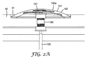
通信システム100は更に、感知型終端部110/RTU 120から地上のSCADA又は無線通信ネットワークへ(かつ地上のSCADA又は無線通信ネットワークから感知型終端部110/RTU 120へ)情報を伝達する送受信部140を更に備える。数個の様々な送受信部の構造140a〜140eが図2A〜図2Eに示され、以下に更に詳細に記載されている。
The
尚、本発明の代替的な態様において、地中データ通信システムは、RTUを完全に省略してもよい。本様式において、送受信部140は、地中機器/監視装置が地上通信ネットワークと通信することができることとなるゲートウェイ部を設けてもよい。いくつかの態様において、送受信部140は、WiFi、WiMax、携帯電話(3G、4G、LTE)、私有認可帯域などの広く利用可能な地上無線通信ネットワークと通信する無線機に結合された環境に対する耐久性を有する地上アンテナを含む。また、この送受信部に、地上無線信号間のインターフェース及び第2のアンテナを介して、又は銅製ケーブル及び/若しくはファイバケーブルによるゲートウェイ部への直接的な接続を介して、地中監視装置/機器への無線通信を提供するゲートウェイ電子装置を含むゲートウェイ部を具備させてもよい。ゲートウェイ部は、地上ネットワークと地下ネットワークとの間のネットワーク接続、セキュリティ、及びデータ変換機能を実行する。
In an alternative aspect of the present invention, the underground data communication system may omit the RTU completely. In this mode, the transmission /
上述のように、一態様において、単一のゲートウェイ部は、ボールト10内に実装された複数の地中監視装置/機器のうち1つ又は2つ以上と通信することができる。上述のように、監視装置は、独立型センサ、又は感知型終端部110の(複数の)センサ部分、及び湿度センサ、大気質センサ、圧力センサなどの他のボールトセンサなどの、ボールト内に配設された機器及び部品と一体化したセンサを含んでもよい。
As described above, in one aspect, a single gateway unit can communicate with one or more of a plurality of underground monitoring devices / devices mounted within the
図2A〜図2Eは、送受信部140の数個の異なる構造を示す。例えば、図2Aは、本体部分142を備えるハウジング141を有する送受信部140aを示す。アンテナ部分147及び(図示しない無線電子装置を備えてもよい)無線機部分は、本体部分142内に配設されてもよい。本構成において、送受信部140aは、地上からボールト10内に入ることができるマンホールの蓋50に装着されている。本態様において、マンホールの蓋50は、送受信部140aの少なくとも基底部分を支持するように構成されている凹部分51を含んでもよい。一態様において、無線機及びアンテナ部品の他に、送受信部140aは、プロセッサ、データストレージ部、通信インターフェース、電源、及びヒューマンインターフェース装置を更に備えてもよい。
2A-2E show several different structures of the transmitter /
ハウジング141は、封止された構造体であってもよく、蓋及びベースプレートなどの1つ又は2つ以上のハウジングのパーツを備えてもよい。ハウジングのパーツの少なくとも一部は、成形性プラスチック材料で製造されてもよい。ハウジングのパーツの材料は、腐食性物質に対して耐性であってもよい。ハウジングは、封止されて、ハウジング内に収容される無線機、アンテナ、及び他の部品を保護することができる。黒鉛含有材料などの適切な材料の封止を使用することによって、外部環境において存在する場合があるガソリン又はオイルのような腐食性物質に対して更なる封止を行うことができる。
The
代替的な態様において、ハウジング141は、成形、加工、又は注型することができる高耐衝撃性樹脂で製造された電波透過性(radio frequency transparent)の路面表示(pavement marker)として構築されてもよい。例示的な代替的な構築物は、その全体が参照により本明細書に援用されている米国特許第6551014号に記載されている。この代替的な態様において、マーカの反射性は、ボールト内の機器の状態を視覚的に示すように変更されてもよい。例えば、明滅する又は明滅しない光は、通常の/通常ではない状態を示してもよい。更に、ゆっくりと明滅するマーカの光は、警告を示してもよく、かつ/又は早く明滅する光は、危険な状況を示してもよい。本例において、液晶フィルタが反射体の前に装着されてもよく、LC極性は、マイクロプロセッサによって調節されてもよい。代替的に、内部光源、例えば、LEDが直接調節されてもよい。
In an alternative embodiment, the
ハウジング141内に収容される電気部品又は電子部品は、能動型、受動型、又は能動型かつ受動型であってもよい。このように、送受信機ハウジング141により、無線機/アンテナがボールト内に位置する、例えば、RTU 120に電気接続することができる一方、地中のボールト又は筐体の外側表面にアンテナを装着することができる。例えば、アンテナ接続部又はコンジット145は、ケーブル130を送受信部140aに連結することができる。本態様において、ケーブル130は、従来の同軸ケーブルであってもよい。コンジット145は、ねじ構造であってもよく、マンホールの蓋50の中へねじ切り加工された適切な大きさの穴の中に螺合させ得る。更に、利用されるアンテナの設計の種類は、マンホールの蓋50を形成するために使用される構造及び材料を考慮することができる。好ましい態様において、多様な大きさ及び組成の既存の蓋は、送受信機/アンテナに合うように容易に変更することができるので、マンホールの蓋50は、通常の従来のマンホールの蓋で構成される。
The electrical or electronic components housed in the
このように、この構造により、感知型終端部のセンサ部分などの監視装置が回線異常を検知した場合、送受信部140aは、リアルタイムの障害の場所情報を電力ユーティリティネットワーク又はSCADAシステムに通信することができる。
In this way, with this structure, when a monitoring device such as a sensor portion of a sensing type terminal detects a line abnormality, the transmission /
図2Bに、本発明の代替の態様を示す。送受信部140bは、本体部分142を含むハウジング141を有し、アンテナ部分147及び無線機部分は、本体部分142内に配設され得る。この特定の構成において、送受信部140bは、実質的にマンホールの蓋50に面一取付けされ、頑強で厚いハウジングを備える。例えば、ハウジングは、ポリカーボネート材料が割れないように柔軟性を提供するリブで補強された領域を有する、ポリウレタンのコアを有するポリカーボネート材料で構成されてもよい。
FIG. 2B shows an alternative aspect of the present invention. The transmission /
アンテナ接続部又はコンジット145は、ケーブル130を送受信部140bに連結することができる。送受信機140bの内部部品及び動作は、上述のように送受信機140aと同一であってもよい。
The antenna connection or
図2Cに、本発明の別の代替の態様を示す。送受信部140cは、本体部分142を含むハウジング141を有し、アンテナ部分147及び無線機部分は、付属の電子部品と共に本体部分142内に配設することができる。この特定の構成において、送受信部140bは、薄いマンホールの蓋50aに凹部取付けされ、このマンホールの蓋に従来のボルトで固定されている。アンテナ接続部又はコンジット145は、ケーブル130を送受信部140へ結合することができる。送受信機140bの内部部品及び動作は、送受信機140aと上述のように同一であってもよい。
FIG. 2C shows another alternative aspect of the present invention. The transmission /
図2D+に、本発明の更に別の代替の態様を示す。送受信部140dは、上部本体部分142及び下部本体部分144を含む二部構成のハウジング141a、141bを有し、上部本体部分142は、第1のアンテナ部分147a及び無線機部分を収納し、下部本体部分144は、第2のアンテナ部分147b及び無線機部分を収納する。第1のアンテナ部分147aは、地上無線ネットワークと通信するように構成されてもよく、第2のアンテナ部分147bは、ケーブル130を介して地下ネットワークと通信するように構成され得る。この特定の構成において、上部本体部分142は、マンホールの蓋50の第1の側に面一取付けされ、下部本体部分144は、マンホールの蓋50の第2の側に面一取付けされる。この具体的な設計により、単一の穴をドリルで開け、マンホールの蓋50内にねじ切り加工された適切な大きさの穴に螺合させ得るねじ型コンジット145を利用することによって、既存のマンホールの蓋にまっすぐに設置することができる。ハウジング141aは、頑強で厚いハウジング材料から形成され得る。下部ハウジング141bは、同一又は異なる材料から形成されてもよい。
FIG. 2D + shows yet another alternative aspect of the present invention. The transmission / reception unit 140d has two-
図2Eに、本発明の更に別の代替の態様を示す。送受信部140eは、上部本体部分142及び下部本体部分144を含む二部構成のハウジング141a、141bを有し、上部本体部分142は、第1のアンテナ部分147a及び無線機部分を収納し、下部本体部分144は、第2のアンテナ部分147b及び無線機部分を収納する。更に、送受信部140eは、データを(例えば、地下で使用されるZigbeeなどの)第1のプロトコルから、(例えば、地上で使用される4Gなどの)第2のプロトコルへ変換するゲートウェイ部143を更に備える。このように、第1のアンテナ部分147aは、地上の無線ネットワークと通信するように構成されてもよく、第2のアンテナ部分147bは、地上の無線ネットワークと異なり得る地下の無線ネットワークと通信するように構成され得る。この特定の構成において、上部本体部分142は、マンホールの蓋50の第1の側に面一取付けされる。別の構造を含んでもよく、又はハウジング141b内に収容されてもよい、ゲートウェイ部143、及び下部本体部分144は、マンホールの蓋50の第2の側に面一取付けされ得る。ゲートウェイ部は、監視装置からデータを受信し、データを読み取り、データを分析し、データを集約し、データを分類し、データに基づいてボールドの状況を推定し、データに基づいて処置を行うための適切な回路及び又は電子部品を備えることができる。更に、ゲートウェイ部143は、イベント相関のためのクロックソースを設けることができる。
FIG. 2E shows yet another alternative aspect of the present invention. The transmission / reception unit 140e has two-
再び、この特定の設計により、単一の穴をドリルで開け、マンホールの蓋50にねじ切り加工された適切な大きさの穴に螺合させ得るねじ型コンジット145を利用することによって、既存のマンホールの蓋にまっすぐに設置することができる。ハウジング141aは、頑強で厚いハウジング材料から形成され得る。下部ハウジング141bは、同一又は異なる材料から形成されてもよい。
Again, this particular design allows existing manholes by utilizing a threaded
一態様において、送受信機及び/又はゲートウェイ部の部品の少なくともいくつかを収納するために利用することができる例示的な構造体は、その全体が参照により本明細書に援用されている米国特許第8135352号に記載されている。 In one aspect, exemplary structures that can be used to house at least some of the transceiver and / or gateway components are incorporated herein by reference in their entirety. 8135352.
別の態様において、複数のアンテナが同一のハウジング(又はハウジング部分)内に埋め込まれてもよく、複数の通信方法が地上及び地下の両方で可能となる。例えば、WiFi及び4Gのアンテナを、GPSアンテナと共に同一の地上アンテナハウジング内に埋め込むことによって、複数のネットワーク接続が可能になると共に、GPSの測位及びタイミング情報が提供され得る。Bluetoothアンテナは、地上ハウジング内に埋め込まれて、送受信部/ゲートウェイ部に近接する作業者へ局所的な通信を提供することができる。例えば、送受信部/ゲートウェイ部を操作している保守要員は、Bluetoothを使用して下のボールト内のセンサを直接読み取ることができるだろう。RFIDアンテナは、地上ハウジング内に埋め込まれてもよく、RFIDリーダで地中センサのデータを読み取ることができる。 In another embodiment, multiple antennas may be embedded in the same housing (or housing portion), allowing multiple communication methods both above ground and underground. For example, by embedding WiFi and 4G antennas together with a GPS antenna in the same ground antenna housing, multiple network connections can be made and GPS positioning and timing information can be provided. The Bluetooth antenna can be embedded in the ground housing to provide local communication to workers in the vicinity of the transmitter / receiver / gateway. For example, a maintenance person operating a transmitter / receiver / gateway could use Bluetooth to directly read the sensor in the vault below. The RFID antenna may be embedded in the ground housing and the RFID reader can read the data of the underground sensor.
別の態様において、多様な手段で地中データ通信システム100の部品に電力を提供することができる。一態様において、ボールト10内の既設のAC又はDC電源を介して機器を稼動することができる。利用可能なAC又はDC電源がない場合、別の態様において、電力をボールト10内の部品に提供することができる終端部110などの電気機器に電力採取コイルが設置されてもよい。代替的に、圧電変換器を利用して、ボールト10内で見られる機械的振動を、電池又は超コンデンサに格納することができる電気エネルギーに変換してもよい。例えば、従来の圧電変換器は、Mide(www.mide.com)から入手可能である。別の態様において、熱電変換器を利用して、地上と地下との間の自然温度の差異を電気エネルギーに変換してもよい。例えば、(http://www.idtechex.com/research/reports/thermoelectric−energy−harvesting−2012−2022−devices−applications−opportunities−000317.asp)を参照。更なる態様では、太陽電池パネルを使用することにより、バッテリ又は他の内部部品へのトリクル充電(trickle powering)が可能である。
In another embodiment, power can be provided to the components of the underground
本発明の別の態様において、複数の地中データ通信システムが、特定のボールトの場所の外側の地中ユーティリティのインフラストラクチャ内に位置する監視装置及び/又は機器と通信するように構成されてもよい。例えば、図3は、低/中/高圧線をボールトへ提供する接合部筐体10cが介在している第1のボールト10a及び第2のボールト10bを有する無線地中マンホールユーティリティのインフラストラクチャを示す。ボールト10aは、(上述の通信システムの実装と同様の様式で構成される)第1の地中データ通信システム100aが実装でき、ボールト10bは、(上述の通信システムの実装と同様の様式でまた構成される)第2の地中データ通信システム100bが実装できる。或る例において、第1の地中データ通信システム100aは、Zigbeeネットワークが実装されている。所望の間隔で、第1の地中データ通信システム100aのRTU又はゲートウェイ部は、ボールト10aと筐体10cとの間の、ボールト10aの外側に位置する接合部108aの状況を監視することができる。更に、第1の地中データ通信システム100aのRTU又はゲートウェイ部は、筐体10cに又はその付近に位置する部品108b及び/又は接合部108cの状況を監視することができる。同様の様式で、第2の地中データ通信システム100bはまた、Zigbeeネットワークを実装することができ、ボールト10bと筐体10cとの間の、ボールト10bの外側に位置する接合部108dの状況を監視することができる。
In another aspect of the invention, even if multiple underground data communication systems are configured to communicate with monitoring devices and / or equipment located within the infrastructure of the underground utility outside the location of a particular vault. good. For example, FIG. 3 shows the infrastructure of a radio underground manhole utility with a
更に、複数の地中データ通信システムは、ユーティリティのSCADAシステムなどの地上ネットワークと通信するのと同様に互いに通信するように構成されてもよい。例えば、第1の地中データ通信システム100aは、地上ネットワークとの通信に加えて、第2の地中データ通信システム100bと直接通信することができる。
Further, the plurality of underground data communication systems may be configured to communicate with each other in the same manner as with a terrestrial network such as a utility SCADA system. For example, the first underground
地中データ通信システムの機能のうちのいくつかを例証した例示的な流れ図を、図4に更に詳細に示す。上記のように、ゲートウェイ部は、独立型装置であってもよく、RTUが組み込まれてもよく、送受信機の一部として組み込まれてもよい。 An exemplary flow chart exemplifying some of the functions of the underground data communication system is shown in more detail in FIG. As described above, the gateway unit may be a stand-alone device, an RTU may be incorporated, or may be incorporated as a part of a transceiver.
本実施形態において、ゲートウェイ部は、送受信機と同じ場所に位置する。監視装置、すなわち、本例において例示的な(前述などの)感知型終端部の電流及び電圧センサとして構成されてもよい能動型センサ260は、送電線のリアルタイムの状況の測定を行う(工程262)。例えば、リアルタイムの状況に対応するアナログ信号は、デジタル化することができる。本例において、RTUへ(無線又は有線のどちらか一方で)測定値を伝達することができ、又は利用されるセンサの種類に応じて、能動型センサ自身によって測定値を処理することができる。データは、RTUへ送られると仮定して、RTUは、周波数及び位相角を算出することによって測定された信号を処理する(工程264)。測定されたデータは、測定データパケットにフォーマットされる(工程266)。データパケットは、その後、ローカルエリアネットワーク(LAN)パケットとして暗号化され送信される(工程268)。この例において、LANは、Zigbee LANであり、RTUは、Zigbee無線機を含む。代替的に、RTUが利用されない場合、信号処理は、監視装置によって行われてもよく、その後、データを直接ゲートウェイ又は最寄りのZigbee無線機に伝達してもよい。
In the present embodiment, the gateway unit is located at the same location as the transceiver. A monitoring device, i.e., an
工程270において、LANパケットは、ゲートウェイ部によって復号及びデコードされる。工程272において、デコードされたデータは、ゲートウェイ部によって解釈される。例えば、ゲートウェイ部は、重要な障害の収集と共にアップロードされて、特定の障害を分類し、又は事前に設定若しくはダウンロードされた条件又は既存の条件の組み合わせに基づいて重症度の割り当てを行う。解釈に基づいて、ゲートウェイ部は、現場での処置を行うべきか否かを判定する(工程275)。現場での処置が必要な場合、ゲートウェイは、信号を機器に伝達して、工程278において処置を行う(例えば、サーキットブレーカを作動させ、コンデンサバンクをオン/オフするなど)。
In
更に、ゲートウェイはまた、工程280において、上流への通知が必要であるか否かを判定してもよい。必要である場合、ゲートウェイ部は、広域ネットワーク(WAN)パケットをフォーマットし(工程282)、WANパケットを暗号化して送信することができる(工程284)。上述のように、WiFi、局所無線などを介してWANパケットを送り出すことができる。WAN受信機(例えば、適切なアプリケーションを搭載した通信装置を有する保守技術員などの移動受信部又はサービスプロバイダのオペレーションセンタなど)は、WANデータパケットを受信することができ、WANパケットを復号及びデコードすることができる(工程286)。WANデータパケットを受信するエンティティ(例えば、オペレーションセンタ又は作業車)はその後、ゲートウェイ部からの通知に従って行動することができる。
Further, the gateway may also determine in
一態様において、この種類の通信システムにより、ユーティリティ供給会社は地中の障害の場所を正確に示すことができるので、送電網内の複数のボールトの場所に入り、物理的に検査する時間及び費用を省くことができる。更に、適切な現場での処置を行うことにより、顧客へのサービスを迅速に復旧することができ、送電網自身への更なる損傷を防止することができる。 In one aspect, this type of communication system allows utility suppliers to pinpoint the location of obstacles in the ground, thus allowing the time and cost of entering and physically inspecting multiple vault locations within the grid. Can be omitted. Further, by taking appropriate on-site measures, the service to the customer can be restored quickly, and further damage to the power grid itself can be prevented.
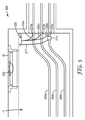
図5に、本発明の別の態様である地中データ通信システム200を示す。通信システム200は、例示的な地中筐体(ここでは地中ボールト11)内に配設されている。この範例的な実装において、ボールト11は、(例えば、低、中若しくは高電圧電力を搬送する)送電線205a〜205cのような、1つ又は2つ以上の送電線を具備する。
FIG. 5 shows an underground
上記と同様、代替の態様において、地中通信システム200は、地上環境内に実装できる。
Similar to the above, in an alternative embodiment, the
図5に戻って参照すると、筐体又はボールト11は、従来形又は修正が施されたマンホールの蓋51のような、金属製又は非金属製であってもよいし従来の円形であってもよい、扉を介して地上からアクセスすることができる。本態様において、ボールト11は、従来の地中ボールトとして構築され、電気、ガス、水、及び/又は他の事業者によって通常使用される。一方、代替の態様において、地中データ通信システム200は、別のタイプの地中筐体で利用することもできるし、又はマンホール、ベースメント、地下室、ピット、シェルタ、管、若しくは他の地中筐体のような同様の構造体内で利用することもできる。
Returning to FIG. 5, the housing or
ボールトはまた、ボールト内に配設された少なくとも1つの監視装置を具備し、この監視装置で、ボールトの物理的状況、又はボールト内に位置する部品若しくは機器の物理的状況を、監視できる。例えば、本態様では、電流の微分に比例する電圧を生成するRogowskiコイルなどの電流センサ(210a〜210c)が、各送電線205a〜205c上に設けられる。代替的に、先に述べたような他のセンサ装置を筐体11の内部で利用することもできる。
The vault also comprises at least one monitoring device disposed within the vault, which can monitor the physical condition of the vault or the physical condition of a component or device located within the vault. For example, in this embodiment, current sensors (210a to 210c) such as a Rogoski coil that generate a voltage proportional to the derivative of the current are provided on each
未加工のデータ信号は、センサから信号線230a〜230cを介して感知型解析部(SAU)220に搬送され得る。SAU220は、ボールト11内の中心位置に、又は壁若しくは他の内部ボールト構造体に沿って装着され得る。SAU 220は、そのようなデータ信号を受信し、操作し、分析し、処理し、又はそれ以外の方法で変換して、監視制御及びデータ取得(SCADA)システム内で使うのに便利な信号にするために、デジタル信号プロセッサ(DSP)又はシステムオンチップ(SOC)を備える。加えて、DSPは、SCADAとは独立にいくつかの操作を実行できる。例えば、DSPでは、障害検出、単離、位置選定、並びに状況監視及びレポーティングを実行できる。そのうえ、DSP/SAUは、ボルト、VAR最適化、フェーザ測定(同期位相計測)、初期障害検出、負荷特性評価、事後イベント分析、署名波形の識別及びイベント捕捉、自己回復及び最適化、エネルギー監査、部分放電、調波分析/低調波分析、フリッカ分析、並びに漏洩電流分析のような付加的な機能が提供されるようにプログラムすることが可能である。
The raw data signal can be conveyed from the sensor to the sensing type analysis unit (SAU) 220 via the
加えて、SAU内で利用されるDSP及び他のチップは、所要電力レベルがわずか10W未満程度に低く抑えられるように構成できる。本態様では、電力採取コイル215を介してSAU220への電力供給を可能にしている。この電力採取コイルを送電線のいずれか1つに連結することによって、電力ケーブル217経由で十分な電力をSAUに供給できる。
In addition, the DSP and other chips used in the SAU can be configured so that the required power level is kept as low as less than 10W. In this aspect, power can be supplied to the
加えて、SAU 220は、バックアップバッテリが実装できる(不図示)。更に、SAU 220は、例えば、筐体内部の環境条件を監視する付加的なセンサを具備し得る。
In addition, the
SAU 220からの処理済みデータは、ネットワーク又はSCADAへ送受信機240を介して通信され得る。図5に示すように、送受信機240は、環境的に堅牢な通信ゲートウェイとして構成される。本態様において、送受信機240は、GPS及び汎用無線機通信モジュールと共に、完全に一体化された極めて低電力の電子装置(時間同期的イベントを検出するためのSOC)を具備し得る。送受信機240は、バッテリ供給源又は無線電力(例えば、無線送電器、不図示)で給電できる。送受信機240は、様々な用途に対応した多様なパッケージ内に様々な付加的なセンサが据え付けられる柔軟性を有するように、モジュラー方式で装着/設計できる。
The processed data from the
図5に示すように、送受信機は、入り口の蓋51上に直接的に装着できる。本態様において、送受信機240の一部分は、入り口の蓋51に形成された穴又はコンジットを貫いて延在するように構成される。加えて、送受信機240の上部は、入り口の蓋51の頂面と実質的に同一平面上にあるように設計される。このようにして、外部要素から送受信機に対し損傷の及ぶリスクが低減される。
As shown in FIG. 5, the transceiver can be mounted directly on the
送受信機240は、短距離通信プロトコル(例えば、bluetooth、WiFi、ZigBee、ANT)を介して、SAU 220のような内部筐体部品と通信できる。このようにして、送受信部240は、地中機器/監視装置(例えば、SAU 220)が地上通信ネットワークに対して通信するのを可能にするゲートウェイを提供し得る。本態様において、送受信部240はまた、上記のように環境に対して耐久性を有する地上アンテナを備える。地上アンテナは、実質的に入り口の蓋の頂面と同一平面上にあるか又は入り口の蓋の頂面上に延在する送受信機240の一部分内に収容可能であり(例えば、図1を参照)、WiFi、WiMax、移動電話(3G、4G、LTE、GSM)、私有認可帯域、非認可帯域などのような広範に利用可能な地上無線通信ネットワークと通信する無線機に連結されている。送受信機240はまた、ゲートウェイ電子装置を具備し得る。このゲートウェイ電子装置は、地上無線機信号間のインターフェースを提供し、第2のアンテナを介して無線でSAU 220と通信する。代替的に、SAU 220は、(図5に示したものでなく図1に示すケーブル130と同様な)銅製ケーブル及び/又はファイバケーブルとの直接的な接続を介して、送受信機240と通信できる。送受信機は、地上ネットワークと地下ネットワークとの間のネットワーク接続、セキュリティ、及びデータ変換機能を実行する。他の態様では、SAUの内部にゲートウェイ電子装置を提供することによって、データパッケージを適切なネットワークフォーマットにフォーマットし、フォーマット済み信号を、標準信号ケーブルを介して送受信機の送信用アンテナに送信できる。
The
本態様において、送受信機240は、少なくとも12〜15年間に格付けされる大型の一次電池を具備する。本態様において、通信システム200は、定期的に稼動することによって送受信機240が使う電力を節減するように構成できる。例えば、1日1回のステータスチェック等に加えて、SAU 220は、問題のある重大なイベントが発生した場合にのみ送受信機240への信号送信を行うようにプログラムできる。
In this aspect, the
代替の態様では、外部電源(例えば、電力採取装置215、又は別の送電線に連結された別の電力採取装置からの利用可能な電力)を介して、送受信機240に給電できる。
In an alternative embodiment, the
更に代替の態様において、地中筐体は、送受信機240の近辺に装着された無線送電器を更に具備し得る。この無線送電器は、(近接場誘導結合のような誘導結合を介して)電力を送受信機に無線で送信できる。例えば、無線送電器は、送受信機240内に位置する第2インダクタに連結される第1の(一次の)インダクタを具備し得る。無線送電器は、地中筐体の内部に装着されたヒンジ付き支持アームを介して、送受信機240に近接近し得る。一態様において、送受信機240までの距離が、使用される搬送周波数の約1/3の波長よりも近づき得るような、無線送電機の操作位置に配置され得る。無線送電器及び送受信機の内部に位置するアンテナは、条件に応じて更に最適化される可能性がある。無線送電器はそれ自体、装置215のような電力採取装置によって給電され得る。
In a further alternative embodiment, the underground enclosure may further comprise a wireless transmitter mounted in the vicinity of the
図6に、本発明の別の態様である通信システム300を示す。通信システム300は、例示的な地中筐体(ここでは地中ボールト11)内に配設されている。この範例的な実装において、ボールト11は、(例えば、中若しくは高圧電力を搬送する)送電線305a〜305cのような、1つ又は2つ以上の高電圧の送電線を具備する。
FIG. 6 shows a
筐体又はボールト11は、金属製又は非金属製であってもよいし従来の円形であってもよい従来の又は修正が施されたマンホールの蓋51などの扉を介して、地上からアクセスできる。本態様において、ボールト11は、従来の地中ボールトとして構築され、電気、ガス、水、及び/又は他のユーティリティによって通常使用される。一方、代替の態様において、地中データ通信システム300は、別のタイプの地中筐体で利用することもできるし、又はマンホール、ベースメント、地下室、ピット、シェルタ、管、若しくは他の地中筐体のような同様の構造体内で利用することもできる。
The housing or
ボールトはまた、ボールト内に配設された少なくとも1つの監視装置を具備し、この監視装置で、ボールトの物理的状況、又はボールト内に位置する部品若しくは機器の物理的状況を、監視できる。 The vault also comprises at least one monitoring device disposed within the vault, which can monitor the physical condition of the vault or the physical condition of a component or device located within the vault.
本態様において、監視装置及びSAUは、感知型ケーブル付属品内部に完全に一体化されている。感知型ケーブル付属品は、この実例では、感知型ケーブル接合部310a〜310cであり、感知型ケーブル付属品の一部として完全に一体化されたシステム解析311a〜311c(DSPチップ及びシステム通信(例えば、Bluetooth)チップを含む)を更に具備する。
In this embodiment, the monitoring device and SAU are fully integrated inside the sensing cable accessory. Sensitive cable accessories are, in this example,
一態様では、必要に応じて、DSPチップ、システム通信チップ、及び他のチップ(例えば、A/Dコンバータ及びタイミングチップ)は、ケーブル接合部の電力搬送導体部の絶縁層の周りに延在する単離された電極要素に連結されている、フレキシブル回路又は小型プリント回路基板(例えば、FR4)に装着できる。このようにして、一体化した感知型ケーブル付属品は、未加工のセンサデータ信号を受信し、操作し、分析し、処理し、又はそれ以外の方法で、監視制御及びデータ取得(SCADA)システム内で使うのに便利な信号に変換できるため、システム300では別個のSAUを必要とせずに済む。
In one aspect, if desired, DSP chips, system communication chips, and other chips (eg, A / D converters and timing chips) extend around the insulating layer of the power carrier conductor portion of the cable junction. It can be mounted on a flexible circuit or small printed circuit board (eg, FR4) connected to an isolated electrode element. In this way, the integrated sensing cable accessory receives, manipulates, analyzes, processes, or otherwise monitors, controls, and data acquisition (SCADA) systems for raw sensor data signals. The
加えて、電力採取装置(例えば、装置315a〜315c)を感知型ケーブル接続310a〜310cの一部として一体化することによって、DSP/Bluetoothチップセットに対し十分な電力を供給することが可能である。本発明の本態様において利用される電力採取装置は、例えば、その全体が参照により援用される欧州特許第EP14169529.6号に記載されているエネルギー採取装置(energy harvesting devices)と同様な方法で構築することができる。この範例的な構築体では、エネルギー採取装置を使用して、感知型ケーブル付属品の一部分として同じ位置に配置された感知装置へ給電することができる。
In addition, by integrating the power extraction device (eg,
感知型ケーブル付属品310a〜310cからの処理済みデータは、送受信機340を介してネットワーク又はSCADAに通信し得る。図6に示すように、送受信機340は、環境的に堅牢な通信ゲートウェイとして構成される。本態様において、送受信機340は、GPS及び汎用無線機通信モジュールと共に、完全に一体化された極めて低電力の電子装置(時間同期イベントを検出するためのSOC)を具備し得る。送受信機340は、先に述べたようなバッテリ供給源を介して給電できる。図6に示すように、送受信機340は、入り口の蓋51に直接的に装着される。加えて、送受信機340の上部は、入り口の蓋51の頂面と実質的に同一平面上にあるように設計される。このようにして、外部要素から送受信機に対し損傷の及ぶリスクが低減される。
The processed data from the
送受信機340は、短距離通信プロトコル(例えば、Bluetooth)を介して、感知型ケーブル付属品310a〜310cのような内部筐体部品と無線で通信できる。本態様において、送受信部340はまた、上記のように環境に対して耐久性を有する地上アンテナを備える。地上アンテナは、入り口の蓋の頂面と実質的に同一平面上にあるか又は入り口の蓋51の頂面上に延在する送受信機340の一部分内に収納可能であり(例えば、図1を参照)、広範に利用可能な地上無線通信ネットワーク(例えば、WiFi、WiMax、移動電話(3G、4G、LTE)、私有認可帯域など)と通信する無線機に連結される。送受信機340はまた、ゲートウェイ電子装置を具備させ得る。このゲートウェイ電子装置により、地上無線機信号間のインターフェースが提供されると共に、第2のアンテナを介して無線で感知型ケーブル付属品との通信が可能になる。
The
代替の態様では、送受信機340は、環境(例えば、気体、煙、温度等)センサのような、1つ又は2つ以上のセンサと更に一体化し得る。送受信機340はまた、DSPチップ、システム通信チップ、及び他のチップ、例えば、環境センサとネットワーク又はSCADAとの間で通信するのに必要なA/Dコンバータ及びタイミングチップなどを具備し得る。
In an alternative embodiment, the
更に、複数の地中データ通信システムは、ユーティリティのSCADAシステムなどの地上ネットワークと通信するのと同様に互いに通信するように構成されてもよい。例えば、第1の地中データ通信システム100aは、地上ネットワークとの通信に加えて、第2の地中データ通信システム100bと直接通信することができる。
Further, the plurality of underground data communication systems may be configured to communicate with each other in the same manner as with a terrestrial network such as a utility SCADA system. For example, the first underground
通信スキームを例証した別の範例的な通信流れ図は、図7に更に詳細に示してある。 Another exemplary communication flow chart exemplifying a communication scheme is shown in more detail in FIG.
システム200の実施形態(図5に示す)と同様な通信ゲートウェイ部は、送受信機240と同じ位置に配置される。他の態様において、通信ゲートウェイ部は、SAUと同じ位置に配置され得る。
A communication gateway unit similar to the embodiment of the system 200 (shown in FIG. 5) is arranged at the same position as the
図7の例では、センサ測定値を、(無線又は有線のどちらか一方で)SAUに通信することも可能であるし、又は利用されるセンサの種類に応じて、能動型センサ自体により処理することも可能である。データがSAUに送信された場合、SAUは1つ又は2つ以上の分析モードを実行することにより、測定された信号を処理する。本例においてSAU220は、本例におけるセンサ310aのような監視装置から、送電線のリアルタイム条件の測定値を記録できる(工程362)。SAU 220は、フォーマットされたデータを送受信部/ゲートウェイ部に送信するかどうか判定する(工程364)。いいえの場合、工程366においてSAUは、データを分析すべきかどうか判定する。データを分析しない場合、このデータはデータストレージに送信される(工程374)。データを分析すべき場合、SAUを介して解析及び/又はイベント検出を実行できる(工程368)。分析に基づいて、SAUは、制御動作のような或る動作を指示し、及び/又はデータをメモリ内に格納できる(工程374)。
In the example of FIG. 7, sensor measurements can also be communicated to the SAU (either wireless or wired) or processed by the active sensor itself, depending on the type of sensor used. It is also possible. When the data is sent to the SAU, the SAU processes the measured signal by performing one or more analysis modes. In this example, the
データを筐体の外部に通信すべき場合、工程375において、フォーマット済み/測定済み/分析済みデータを送受信部/ゲートウェイ部(無線で又は通信回線経由のいずれかで)に通信する。本態様において、送受信機240は典型的にスリープモードに維持され(工程380)、データストレージ内に格納されているSAUからデータ信号を受信した際(工程376)、起動の信号が出される(工程377)。それ以外の場合、本態様において、送受信部/ゲートウェイ部は、所定の時間に起動される。
When the data should be communicated to the outside of the housing, in
工程378において、(SAU又は送受信部/ゲートウェイ部のいずれかで)データを送信する決定が為される。データを送信しない場合、送受信部/ゲートウェイ部をスリープモードに戻すことができる(工程380)。データパッケージはゲートウェイ部を介して初期化され、送受信機から標準又はプライベートテレコミュニケーションプロトコル(工程399)を介して、クラウドデータサービス又はSCADA(工程398)に伝達される。その後、データを受信するエンティティ(例えば、オペレーションセンタ又は作業車)は、送受信部/ゲートウェイ部からの通知に従って作動し得る。例えば、WAN受信機(例えば、適切なアプリケーションを搭載した通信装置を有する保守技術員などの移動受信部又はサービスプロバイダのオペレーションセンタなど)は、送受信機からパケットデータを受信して、情報の照会、復号及び/又はデコードを行うことができる(工程390)。この情報は、インターネット又はネットワーク通信(工程395)経由でクラウドデータサービス又はSCADA(398)に対して通信でき、その際、ウェブアプリケーションによるデータ消費を伴う(工程396)。例えば、工程396では、REST(REpresentational State Transfer)が生起され、それにより、サーバ上で情報の作成、読み取り、更新、及び/又は削除が行われる。
In
一態様において、この種類の通信システムにより、ユーティリティ供給会社は地中の障害の場所を正確に示すことができるので、送電網内の複数のボールトの場所に入り、物理的に検査する時間及び費用を節減できる。更に、適切な現場での処置を行うことにより、顧客へのサービスを迅速に復旧することができ、送電網自身への更なる損傷を防止することができる。更に、この通信システムでは、ユーティリティが特定の筐体、送受信機、及び/又はSAUに対して直接的に通信し、システム設定、表、電力及び環境感知の閾値を再構成又は更新することを可能にしている。 In one aspect, this type of communication system allows utility suppliers to pinpoint the location of obstacles in the ground, thus allowing the time and cost of entering and physically inspecting multiple vault locations within the grid. Can be saved. Further, by taking appropriate on-site measures, the service to the customer can be restored quickly, and further damage to the power grid itself can be prevented. In addition, this communication system allows utilities to communicate directly with specific enclosures, transceivers, and / or SAUs to reconfigure or update system settings, tables, power and environmental sensing thresholds. I have to.
上記と同様、代替の態様では、低、中、又は高電圧ケーブルが地中から進入して地盤面機器内に露出されるように、地中通信システム300を地上環境に実装できる。例えば、感知型ケーブル接合部及び送受信機を、地上の変圧器筐体内に実装することもできる。例えば、これらの通信システムのうちの1つ又は2つ以上を利用できる地盤水準又は地上装置には、例えば、電力又は配電用変圧器、モーター、スイッチ装置、コンデンサバンク及びジェネレータが包含される。加えて、これらの通信システムのうちの1つ又は2つ以上を、橋、陸橋、車両及びサイン監視、地下鉄、ダム、トンネル並びに建物などの自己監視アプリケーション内に実装できる。監視装置自体又はSAUとの組み合わせは、イベント発生、同定、位置選定、及び自己給電部を介して講じられる措置により駆動される極めて低電力の計算処理機能が要求されるシステム内に実装され得る。更に、GPS機能を時間同期イベントと統合し、一連の閾値及びアルゴリズムを用いることにより、様々な重要な構造体又はユーティリティ部品の初期適用(incipient application)/障害/劣化が早期のうちに検出され、重大な問題が突き止められる。別の変数は、非破壊的な機械的構成であり、かなりの危険性がある用途にも利用できる。
Similar to the above, in an alternative embodiment, the
例えば、図8に、通信システム400を具備する地盤又は地上に実装可能な、範例的な筐体20を示す。この範例的な実装において、筐体20は、(例えば、低、中若しくは高圧電力を搬送する)送電線405a〜405cのような、1つ又は2つ以上の送電線を具備する。代替の態様では、コンデンサバンク、モーター、スイッチ装置、電力又は配電用変圧器、ジェネレータ、及び/又は他のユーティリティ機器を筐体20に収容できる。
For example, FIG. 8 shows a
筐体20はまた、ボールト内に配設された少なくとも1つの監視装置を具備し、この監視装置で、ボールトの物理的状況、又はボールト内に位置する部品若しくは機器の物理的状況を、監視できる。例えば、本態様では、電流の微分に比例する電圧を生成するRogowskiコイルなどの電流センサ(410a〜410c)が、各送電線405a〜405c上に設けられる。また、加えて、環境センサ413も具備させ得る。また、先に述べたような他のセンサ装置を筐体20の内部で利用することもできる。
The
未加工のデータ信号は、センサから信号線430a〜430cを介して感知型解析部(sensored analytics unit)(SAU)420に搬送され得る。SAU 420は、筐体20内の中心位置に、又は壁若しくは他の内部構造体に沿って装着され得る。SAU 420は、そのようなデータ信号を受信し、操作し、分析し、処理し、又はそれ以外の方法で変換して、監視制御及びデータ取得(SCADA)システム内で使うのに便利な信号にするために、デジタル信号プロセッサ(DSP)又はシステムオンチップ(SOC)を備える。加えて、DSPは、SCADAとは独立にいくつかの操作を実行できる。例えば、DSPでは、障害検出、単離、位置選定、並びに状況監視及びレポーティングを実行できる。そのうえ、DSP/SAUは、ボルト、VAR最適化、フェーザ測定(同期位相計測)、初期障害検出、負荷特性評価、事後イベント分析、署名波形の識別及びイベント捕捉、自己回復及び最適化、エネルギー監査、部分放電、調波分析/低調波分析、フリッカ分析、並びに漏洩電流分析のような付加的な機能が提供されるようにプログラムすることが可能である。
The raw data signal can be conveyed from the sensor to the sensored analytics unit (SAU) 420 via
加えて、SAU内で利用されるDSP及び他のチップは、所要電力レベルがわずか10W未満程度に低く抑えられるように構成できる。本態様では、電力採取コイル415を介してSAU 420への電力供給を可能にしている。この電力採取コイルを送電線のいずれか1つに連結することによって、電力ケーブル417経由で十分な電力をSAUに供給できる。加えて、SAU 420は、バックアップバッテリが実装できる(不図示)。
In addition, the DSP and other chips used in the SAU can be configured so that the required power level is kept as low as less than 10W. In this aspect, power can be supplied to the
SAU420からの処理済みデータは、送受信機440経由でネットワーク又はSCADAに通信し得る。本態様において、送受信機440は、GPS及び汎用無線機通信モジュールと共に、完全に一体化された極めて低電力の電子装置(時間同期的イベントを検出するためのSOC)を具備し得る。送受信機440は、筐体20、バッテリ供給源又は無線電力(例えば、無線送電器、不図示)の内部にあるライン電源を介して給電できる。SAU420は、銅製ケーブル及び/又はファイバケーブル431との直接的な接続を介して送受信機440と通信できる。
The processed data from the
本態様において、送受信機440は、筐体20の頂面(又は他の)面上に直接的に装着できる。送受信機440は、ケーブル430a〜430cを介してSAU 420のような内部筐体部品と通信する。必要な場合、送受信機420は、ネットワーク接続、セキュリティ、並びに外部及び内部ネットワーク間のデータ変換機能を実行できる。
In this embodiment, the
別の態様において、SAU 420は、モジュラー部又はアップグレード可能部として構成できる。そのようなモジュラー部は、1つ又は2つ以上のインターフェースポートを介してドングル又は別個のモジュールの連結を可能にし得る。図8に示すように、複数のセンサ(410a〜410c、413)は、SAU 420に接続される。そのような構成は、電力線及び/又は多様な付加的な環境センサ(気体、水、振動、温度、酸素レベル等のようなパラメータを検出できるセンサ413と同様なセンサ)を監視することを、可能にし得る。例えば、代替の一態様では、センサ413に、筐体内部の環境及び部品の温度プロファイルを観察するための、熱探知カメラを具備させることができる。上述のDSP/他のチップは計算処理機能を備えて、送受信機440を解釈し、フィルタし、活性化し、設定し、かつ/又はその送受信機と通信することができる。ドングル又はコネクタブロックに、付加的な回路網を収容することによって、アナログ−デジタルフロントエンドを生じさせ得る。また、このドングル又はコネクタブロックに、プラグアンドプレイ電気回路を具備させることによって、挿入された感知モジュールの自動識別及び認識(並びに適切な同期化、タイミング、及び他の適切な通信条件の自動セットアップ)が可能になる。
In another aspect, the
図9に、本発明の別の態様である地中データ通信システム500を示す。通信システム500は、例示的な地中筐体(ここでは地中ボールト11)内に配設されている。この範例的な実装において、ボールト11は、(例えば、低、中若しくは高圧電力を搬送する)送電線505a〜505cのような、1つ又は2つ以上の送電線を具備する。
FIG. 9 shows an underground
筐体又はボールト11は、修正済みマンホールの蓋50’とリング又はフランジ52とを具備する入り口ポート55を介して、地上からアクセスできる。本態様において、ボールト11は、従来の地中ボールトとして構築され、電気、ガス、水、及び/又は他の事業者によって通常使用される。一方、代替の態様において、地中データ通信システム500は、別のタイプの地中筐体で利用することもできるし、又はマンホール、ベースメント、地下室、ピット、シェルタ、管、若しくは他の地中筐体のような同様の構造体内で利用することもできる。
The housing or
ボールトはまた、ボールト内に配設された少なくとも1つの監視装置を具備し、この監視装置で、ボールトの物理的状況、又はボールト内に位置する部品若しくは機器の物理的状況を、監視できる。例えば、本態様では、電流の微分に比例する電圧を生成するRogowskiコイルなどの電流センサ(510a〜510c)が、各送電線505a〜505c上に設けられる。代替的に、先に述べたような他のセンサ装置を筐体11の内部で利用することもできる。
The vault also comprises at least one monitoring device disposed within the vault, which can monitor the physical condition of the vault or the physical condition of a component or device located within the vault. For example, in this embodiment, current sensors (510a to 510c) such as a Rogoski coil that generate a voltage proportional to the derivative of the current are provided on each
未加工のデータ信号は、センサから信号線530a〜530cを介して感知型解析部(SAU)520に搬送され得る。SAU 520は、ボールト11内の中心位置に、又は壁若しくは他の内部ボールト構造体に沿って装着され得る。図9に示すように、SAUは、ボールト11の頂壁上に装着できる。SAU 520は、そのようなデータ信号を受信し、操作し、分析し、処理し、又はそれ以外の方法で変換して、監視制御及びデータ取得(SCADA)システム内で使うのに便利な信号にするために、デジタル信号プロセッサ(DSP)又はシステムオンチップ(SOC)を備える。加えて、DSPは、SCADAとは独立にいくつかの操作を実行できる。例えば、DSPでは、障害検出、単離、位置選定、並びに状況監視及びレポーティングを実行できる。そのうえ、DSP/SAUは、ボルト、VAR最適化、フェーザ測定(同期位相計測)、初期障害検出、負荷特性評価、事後イベント分析、署名波形の識別及びイベント捕捉、自己回復及び最適化、エネルギー監査、部分放電、調波分析/低調波分析、フリッカ分析、並びに漏洩電流分析のような付加的な機能が提供されるようにプログラムすることが可能である。
The raw data signal can be conveyed from the sensor to the sensing type analysis unit (SAU) 520 via the signal lines 530a to 530c. The SAU 520 can be mounted at a central location within the
加えて、SAU内で利用されるDSP及び他のチップは、所要電力レベルがわずか10W未満程度に低く抑えられるように構成できる。本態様では、電力採取コイル515を介してSAU 520への電力供給を可能にしている。この電力採取コイルを送電線のいずれか1つに連結することによって、電力ケーブル517経由で十分な電力をSAUに供給できる。
In addition, the DSP and other chips used in the SAU can be configured so that the required power level is kept as low as less than 10W. In this aspect, power can be supplied to the SAU 520 via the
加えて、SAU 520は、バックアップバッテリが実装できる(不図示)。更に、SAU520は、例えば、筐体内部の環境条件を監視する付加的なセンサを具備し得る。 In addition, the SAU 520 can be equipped with a backup battery (not shown). Further, the SAU520 may include, for example, an additional sensor that monitors the environmental conditions inside the housing.
SAU 520からの処理済みデータは、送受信機540経由でネットワーク又はSCADAに通信し得る。本態様において、送受信機540は、GPS及び汎用無線機通信モジュールと共に、完全に一体化された極めて低電力の電子装置(時間同期的イベントを検出するためのSOC)を具備し得る。送受信機540は、バッテリ供給源又は無線電力(例えば、無線送電器、不図示)で給電できる。SAU 520は、銅製ケーブル及び/又はファイバケーブル531との直接的な接続を介して、送受信機540に通信できる。代替的に、また、この送受信機540に、地上無線機信号間のインターフェースを提供するゲートウェイ電子装置を具備させることも可能であり、それにより、第2のアンテナを介して無線でSAU 520と通信する。
The processed data from the SAU 520 may communicate with the network or SCADA via the
本態様において、送受信機540は、入り口ポート55のリング又はフランジ部分52上に直接的に装着できる。本態様において、ブラケット又は装着用構造体541は、リング又はフランジ52に装着し、その内部に送受信機540を固定するように構成できる。入り口の蓋50‘は、その周辺部に沿ったカットアウト部分53を具備し得る。このカットアウト部分は、送受信機/ブラケット構造体の外形に適合する。このようにして、送受信機540の上部は、入り口の蓋50’の頂面と実質的に同一平面上にあるように設計され、ゆえに、外部要素から送受信機540に対し損傷の及ぶリスクが低減される。加えて、入り口の蓋50‘が正しく取り外さない場合、送受信機540が損傷するリスク、又はケーブル531が切断されるリスクが低減される。
In this embodiment, the
送受信機540は、ケーブル530a〜530c経由で、及び/又は短距離通信プロトコル(例えば、bluetooth、WiFi、ZigBee、ANT)経由で、SAU 520のような内部筐体部品と通信し得る。このようにして、送受信部540は、地中機器/監視装置(例えば、SAU 520)が地上通信ネットワークに対して通信するのを可能にするゲートウェイを提供し得る。本態様において、送受信部540はまた、上記のような環境に対して耐久性を有する地上アンテナを備える。地上アンテナは、入り口の蓋の頂面と実質的に同一平面上にある送受信機540の一部分内に収容可能であり、WiFi、WiMax、移動電話(3G、4G、LTE、GSM)、私有認可帯域、非認可帯域などのような広範に利用可能な地上無線通信ネットワークと通信する無線機に連結される。送受信機は、ネットワーク接続、セキュリティ、及び地上と地中ネットワークとの間のデータ変換機能を実行する。他の態様では、SAUの内部にゲートウェイ電子装置を提供することによって、データパッケージを適切なネットワークフォーマットにフォーマットし、フォーマットされた信号を、標準信号ケーブルを介して送受信機の送信用アンテナに送信できる。
The
これまで、本発明について、いくつかの個々の実施形態を参照して説明してきた。上記の詳細な説明は、あくまで理解を助けるために示したものに過ぎない。詳細な説明から不要な限定はないと理解又は解釈すべきである。方向についての言及並びに右、左、前、後ろ、上、及び下についての言及は全て、単なる例示であって、特許請求に係る発明を限定するものではない。本発明の範囲から逸脱することなく、記載された実施形態において多くの変更を行うことができることが当業者には明白であろう。したがって、本発明の範囲は、本明細書に記載された詳細及び構造に限定されるべきではなく、特許請求の範囲の文言による記載、及びそれらの構造の等価物によって限定される。
以下、本発明の態様について説明する。
〔態様1〕
筐体への入り口ポート上に配設され、かつハウジングを具備する送受信機であって、前記ハウジングが前記入り口に装着可能であり、前記送受信機が、前記筐体の外部のネットワークと通信するように構成される、送受信機と、
前記筐体内のリアルタイムの状況に関するデータを提供する、前記筐体内に配設された、監視装置と、
前記監視装置/センサからのデータを処理し、処理済みデータ信号を生成して、前記処理済みデータ信号を前記送受信機に通信する、センサ解析部と、
を具備する、データ通信システム。
〔態様2〕
前記監視装置は、センサを含む、態様1に記載のデータ通信システム。
〔態様3〕
前記センサが、電力、電圧、電流、温度、可燃物質又は燃焼副産物、機械的歪み、機械的移動、湿度、土壌状態、圧力、危険雰囲気、液体フロー、漏れ、部品寿命又は耐用年限、人感、物理的状態、光レベル、及び振動のうち少なくとも1つを検出する、態様2に記載のデータ通信システム。
〔態様4〕
前記センサが、感知型ケーブル付属品に組み込まれ、電力ケーブルの状況を監視するように構成されている、態様2に記載のデータ通信システム。
〔態様5〕
前記送受信機が通信ゲートウェイ部を具備する、態様1に記載のデータ通信システム。
〔態様6〕
前記センサ解析部がデジタル信号プロセッサを具備する、態様1に記載のデータ通信システム。
〔態様7〕
前記センサ解析部が無線ネットワーク通信チップを具備する、態様1に記載のデータ通信システム。
〔態様8〕
前記送受信部が、耐久性を有する地上アンテナ及び無線機を具備する、態様1に記載のデータ通信システム。
〔態様9〕
前記送受信機が、集約された情報を、地上にある上流の別の集約ノード又はクラウドサーバに送信するように構成されている、態様1に記載のデータ通信システム。
〔態様10〕
前記集約されたデータは、定期的な状態通知及び非同期警報通知のうち1つ又は2つ以上を含む、態様9に記載のデータ通信システム。
〔態様11〕
前記送受信機が、集約ノード又はクラウドによって前記送受信機に送信されたメッセージに対して応答するように構成される、態様1に記載のデータ通信システム。
〔態様12〕
前記筐体が地中筐体を備え、前記入り口ポートがマンホールの蓋と、前記マンホールの蓋を受容するリング部分と、を備える、態様1に記載のデータ通信システム。
〔態様13〕
前記送受信機が、前記マンホールの蓋に固定され、かつ前記入り口の蓋内に形成された穴を貫通して延在する前記送受信機ハウジングの一部分にも固定されている、態様12に記載のデータ通信システム。
〔態様14〕
前記入り口の蓋内に形成された穴を貫通して延在する前記送受信機ハウジング部分が、前記入り口の蓋の頂面と実質的に同一平面上にある、態様13に記載のデータ通信システム。
〔態様15〕
前記送受信機が前記入り口ポートのリング部分に固定されている、態様12に記載のデータ通信システム。
〔態様16〕
前記筐体内に位置する少なくとも1つの電力線に連結された電力採取装置を更に具備する、態様1に記載のデータ通信システム。
〔態様17〕
前記電力採取装置が、前記センサ解析部に連結され、かつ前記センサ解析部に電力を供給する、態様16に記載のデータ通信システム。
〔態様18〕
前記センサ解析部が、1つ又は2つ以上の環境センサに接続するように構成される複数のインターフェースポートを含む、態様1に記載のデータ通信システム。
〔態様19〕
前記送受信機が誘導結合を介して給電される、態様1に記載のデータ通信システム。〔態様20〕
地中筐体への入り口ポート上に配設された送受信機であって、前記送受信機が、前記入り口ポートに装着可能なハウジングを具備し、前記地中筐体の外部のネットワークと通信するように構成されている、送受信機と、
前記地中筐体内に位置する電力線に装着された感知型ケーブル付属品であって、前記地中筐体内部のリアルタイム状況に関連するデータを測定するセンサと、前記測定されたデータを処理する信号処理チップと、処理されたデータを前記送受信機に通信する通信チップと、を具備する、感知型ケーブル付属品と、
を備える、データ通信システム。
〔態様21〕
前記感知型ケーブル付属品が、前記信号処理チップ及び通信チップに対し電力を供給するために前記電力線に連結した電力採取装置を更に備える、態様20に記載のデータ通信システム。
〔態様22〕
ユーティリティ機器が収容される筐体の一部分の上に配設され、前記筐体に装着可能なハウジングを具備する送受信機であって、前記送受信機が前記筐体の外部のネットワークと通信するように構成されている、送受信機と、
前記筐体内に配設され、前記筐体内のリアルタイム状況に関するデータを提供する、監視装置と、
前記監視装置からのデータを処理し、処理済みデータ信号を生成して、前記処理済みデータ信号を前記送受信機に通信する、センサ解析部と、
を具備する、データ通信システム。
〔態様23〕
前記筐体が地中ボールトを備える、態様21に記載のデータ通信システム。
〔態様24〕
前記筐体が、地面レベル筐体又は地上筐体を備える、態様21に記載のデータ通信システム。
So far, the present invention has been described with reference to some individual embodiments. The detailed explanation above is provided only to aid understanding. It should be understood or interpreted that there are no unnecessary limitations from the detailed explanation. References to directions and references to right, left, front, back, top, and bottom are all merely examples and do not limit the claimed invention. It will be apparent to those skilled in the art that many modifications can be made in the described embodiments without departing from the scope of the invention. Therefore, the scope of the present invention should not be limited to the details and structures described herein, but to the wording of the claims and their structural equivalents.
Hereinafter, aspects of the present invention will be described.
[Aspect 1]
A transceiver disposed on an entrance port to a housing and comprising a housing so that the housing can be mounted at the entrance and the transceiver communicates with a network outside the housing. Consists of a transceiver and
A monitoring device disposed in the housing and providing data on the real-time situation in the housing.
A sensor analysis unit that processes data from the monitoring device / sensor, generates a processed data signal, and communicates the processed data signal to the transceiver.
A data communication system.
[Aspect 2]
The data communication system according to
[Aspect 3]
The sensor is used for power, voltage, current, temperature, flammable substances or combustion by-products, mechanical strain, mechanical movement, humidity, soil condition, pressure, dangerous atmosphere, liquid flow, leakage, component life or useful life, human sensation, The data communication system according to aspect 2, wherein at least one of physical state, light level, and vibration is detected.
[Aspect 4]
The data communication system according to aspect 2, wherein the sensor is incorporated in a sensing cable accessory and is configured to monitor the status of the power cable.
[Aspect 5]
The data communication system according to
[Aspect 6]
The data communication system according to
[Aspect 7]
The data communication system according to
[Aspect 8]
The data communication system according to
[Aspect 9]
The data communication system according to
[Aspect 10]
The data communication system according to aspect 9, wherein the aggregated data includes one or more of periodic status notifications and asynchronous alarm notifications.
[Aspect 11]
The data communication system according to
[Aspect 12]
The data communication system according to
[Aspect 13]
12. The data according to aspect 12, wherein the transceiver is fixed to the manhole cover and also to a portion of the transceiver housing that extends through a hole formed in the entrance cover. Communications system.
[Aspect 14]
13. The data communication system according to aspect 13, wherein the transceiver housing portion extending through a hole formed in the entrance lid is substantially flush with the top surface of the entrance lid.
[Aspect 15]
The data communication system according to aspect 12, wherein the transceiver is fixed to a ring portion of the inlet port.
[Aspect 16]
The data communication system according to
[Aspect 17]
The data communication system according to aspect 16, wherein the power sampling device is connected to the sensor analysis unit and supplies electric power to the sensor analysis unit.
[Aspect 18]
The data communication system according to
[Aspect 19]
The data communication system according to
A transceiver disposed on an entrance port to the underground housing so that the transceiver has a housing that can be attached to the entrance port and communicates with a network outside the underground housing. The transceiver and the transmitter / receiver, which are configured in
A sensor that is a sensing type cable accessory attached to a power line located in the underground housing and measures data related to a real-time situation inside the underground housing, and a signal for processing the measured data. A sensory cable accessory comprising a processing chip and a communication chip that communicates processed data to the transmitter / receiver.
A data communication system.
[Aspect 21]
20. The data communication system according to
[Aspect 22]
A transceiver that is disposed on a portion of a housing in which utility equipment is housed and has a housing that can be mounted on the housing so that the transceiver communicates with a network outside the housing. It is configured with a transceiver and
A monitoring device, which is arranged in the housing and provides data on a real-time situation in the housing.
A sensor analysis unit that processes data from the monitoring device, generates a processed data signal, and communicates the processed data signal to the transceiver.
A data communication system.
[Aspect 23]
21. The data communication system according to aspect 21, wherein the housing comprises an underground vault.
[Aspect 24]
21. The data communication system according to aspect 21, wherein the housing includes a ground level housing or a ground housing.
Claims (3)
前記筐体内に位置する部品のリアルタイムの状況に関するデータを提供する、前記筐体内に配設された、監視装置と、
前記監視装置からのデータを処理し、処理済みデータ信号を生成して、前記処理済みデータ信号を前記送受信機に通信する、解析部と、
を具備し、
前記解析部は、前記部品の障害検出を提供する、データ通信システム。 A transceiver which is arranged on an entrance port to a housing and has a radio wave transmitting housing, wherein the housing is mounted in a through hole provided in a lid of the entrance port, and the transceiver is provided. but includes a GPS antenna that provides GPS positioning and timing information, Ru is configured to communicate with an external network of the housing, a transceiver,
A monitoring device disposed in the housing and providing data on the real-time status of the components located in the housing.
Processing data from the monitoring device, to generate processed data signals, communicating the processed data signal to the transceiver, and the solution analyzing unit,
Equipped with
Before Machinery analyzing unit is, that provides a fault discovery of the parts, the data communication system.
前記地中筐体内に位置する電力線に装着された感知型ケーブル付属品であって、前記地中筐体内部のリアルタイム状況に関連するデータを測定するセンサと、前記測定されたデータを処理する信号処理チップと、処理されたデータを前記送受信機に通信する通信チップと、を具備する、感知型ケーブル付属品と、
を備え、
前記感知型ケーブル付属品は、前記電力線の障害検出を提供する、データ通信システム。 A transceiver disposed on an entrance port to an underground housing, wherein the transceiver includes a radio wave transmitting housing mounted in a through hole provided in a lid of the entrance port, and has a GPS. includes a GPS antenna which provides positioning and timing information, Ru is configured to communicate with an external network of the underground housing, a transceiver,
A sensor that is a sensing type cable accessory attached to a power line located in the underground housing and measures data related to a real-time situation inside the underground housing, and a signal for processing the measured data. A sensory cable accessory comprising a processing chip and a communication chip that communicates processed data to the transmitter / receiver.
With
The sensing cable accessories, that provide fault discovery of the power line, the data communication system.
前記筐体内に配設され、前記筐体内に位置する部品のリアルタイム状況に関するデータを提供する、監視装置と、
前記監視装置からのデータを処理し、処理済みデータ信号を生成して、前記処理済みデータ信号を前記送受信機に通信する、解析部と、
を具備し、
前記解析部は、前記部品の障害検出を提供する、データ通信システム。 A transceiver provided on a radio wave transmitting housing arranged on an entrance port to a housing in which an infrastructure device is housed and mounted in a through hole provided in a lid of the entrance port. machine comprises a GPS antenna that provides GPS positioning and timing information, Ru is configured to communicate with an external network of the housing, a transceiver,
A monitoring device that is disposed in the housing and provides data on the real-time status of components located in the housing.
Processing data from the monitoring device, to generate processed data signals, communicating the processed data signal to the transceiver, and the solution analyzing unit,
Equipped with
Before Machinery analyzing unit is, that provides a fault discovery of the parts, the data communication system.
Applications Claiming Priority (7)
| Application Number | Priority Date | Filing Date | Title |
|---|---|---|---|
| US201462014764P | 2014-06-20 | 2014-06-20 | |
| US62/014,764 | 2014-06-20 | ||
| PCT/US2014/054905 WO2015041906A1 (en) | 2013-09-18 | 2014-09-10 | Underground data communication apparatus, system, and method |
| USPCT/US2014/054905 | 2014-09-10 | ||
| US201562138176P | 2015-03-25 | 2015-03-25 | |
| US62/138,176 | 2015-03-25 | ||
| PCT/US2015/036345 WO2015195861A1 (en) | 2014-06-20 | 2015-06-18 | Data communication apparatus, system, and method |
Publications (3)
| Publication Number | Publication Date |
|---|---|
| JP2017524177A JP2017524177A (en) | 2017-08-24 |
| JP2017524177A5 JP2017524177A5 (en) | 2018-07-26 |
| JP6955868B2 true JP6955868B2 (en) | 2021-10-27 |
Family
ID=54936091
Family Applications (1)
| Application Number | Title | Priority Date | Filing Date |
|---|---|---|---|
| JP2016574099A Active JP6955868B2 (en) | 2014-06-20 | 2015-06-18 | Data communication equipment, systems, and methods |
Country Status (12)
| Country | Link |
|---|---|
| US (5) | US9961418B2 (en) |
| EP (1) | EP3158688A4 (en) |
| JP (1) | JP6955868B2 (en) |
| KR (1) | KR102339551B1 (en) |
| CN (1) | CN106464548B (en) |
| AU (1) | AU2015277152B2 (en) |
| BR (1) | BR112016028680B1 (en) |
| CA (1) | CA2952942C (en) |
| MX (1) | MX357756B (en) |
| SG (1) | SG11201610428UA (en) |
| TW (1) | TWI676373B (en) |
| WO (1) | WO2015195861A1 (en) |
Families Citing this family (29)
| Publication number | Priority date | Publication date | Assignee | Title |
|---|---|---|---|---|
| WO2015171387A1 (en) * | 2014-05-07 | 2015-11-12 | Thomson Licensing | A self-contained deadbolt sensing arrangement |
| EP3158688A4 (en) * | 2014-06-20 | 2018-02-28 | 3M Innovative Properties Company | Data communication apparatus, system, and method |
| US11264710B2 (en) | 2016-02-04 | 2022-03-01 | 3M Innovative Properties Company | Mounting structure for data communication apparatus and system |
| JP2018013942A (en) * | 2016-07-20 | 2018-01-25 | 日立化成株式会社 | Monitoring system and monitoring method |
| TW202347973A (en) * | 2016-10-27 | 2023-12-01 | 美商李爾登公司 | Systems and methods for distributing radioheads |
| US11026068B2 (en) | 2017-01-05 | 2021-06-01 | 3M Innovative Properties Company | Wireless sensor communication system for enclosures |
| CN107341119A (en) * | 2017-07-05 | 2017-11-10 | 深圳市宇峰通讯设备有限公司 | Data transmission circuit and its communication means and multifunctional base |
| FR3071521A1 (en) * | 2017-09-26 | 2019-03-29 | Orange | COVER FOR VISIBLE ROOM VISIBLE TO RADIO FREQUENCY SIGNALS |
| WO2019180566A1 (en) * | 2018-03-22 | 2019-09-26 | 3M Innovative Properties Company | Data communication sensing and monitoring system mountable in support structure |
| US10990068B2 (en) | 2018-05-29 | 2021-04-27 | Abb Schweiz Ag | Technologies for providing cloud-based management of an electrical grid |
| US20210266025A1 (en) * | 2018-08-22 | 2021-08-26 | 3M Innovative Properties Company | Data communication transceiver assembly and method for integration into entrance ports for underground enclosures |
| EP3841389A4 (en) * | 2018-08-22 | 2022-05-25 | 3M Innovative Properties Company | Fault circuit indicator apparatus, system, and method |
| US20210373063A1 (en) * | 2018-09-10 | 2021-12-02 | 3M Innovative Properties Company | Method and system for monitoring a health of a power cable accessory based on machine learning |
| US10883347B2 (en) * | 2018-12-03 | 2021-01-05 | Novinium, Inc. | Methods and systems for detecting manhole events |
| US10883348B2 (en) | 2018-12-03 | 2021-01-05 | Novinium, Inc. | Flow restrictor for installation in an underground conduit connected to an underground vault |
| US11171402B2 (en) * | 2018-12-21 | 2021-11-09 | HYDRO-QUéBEC | Wireless telecommunication system for an equipment in an underground structure |
| WO2020178664A1 (en) * | 2019-03-05 | 2020-09-10 | 3M Innovative Properties Company | Cable harness and asset indicator device for a data communication sensing and monitoring system |
| US11261530B2 (en) * | 2019-03-11 | 2022-03-01 | Prorbar, Inc. | Cathodic protection system and miniaturized constant current rectifier |
| US10607475B1 (en) | 2019-03-21 | 2020-03-31 | Underground Systems, Inc. | Remote monitoring system |
| US11060312B1 (en) * | 2019-05-06 | 2021-07-13 | Amazon Technologies, Inc. | Data center network tunnel |
| US11313895B2 (en) * | 2019-09-24 | 2022-04-26 | Rosemount Inc. | Antenna connectivity with shielded twisted pair cable |
| BR112022012941A2 (en) | 2019-12-31 | 2022-09-13 | 3M Innovative Properties Co | LOCAL PARTIAL DISCHARGE MONITORING |
| CN111510853A (en) * | 2020-04-16 | 2020-08-07 | 合肥工大高科信息科技股份有限公司 | Mine positioning label system and positioning method |
| AU2021348426A1 (en) * | 2020-09-24 | 2023-05-04 | Hynds Limited | A remote sensing device |
| US11792950B2 (en) * | 2021-01-15 | 2023-10-17 | Amir KHALAJI | Modular upgradable low voltage power supply |
| EP4341704A1 (en) * | 2021-05-17 | 2024-03-27 | Tammerfast OY | Monitoring system for underground transmission cables |
| CN117642950A (en) | 2021-06-28 | 2024-03-01 | 3M创新有限公司 | Multifunctional high-density power grid monitoring |
| TWI816457B (en) * | 2022-07-01 | 2023-09-21 | 華景電通股份有限公司 | Monitoring system |
| WO2024058813A1 (en) | 2022-09-16 | 2024-03-21 | 3M Innovative Properties Company | Multimode sensing system for medium and high voltage cables and equipment |
Family Cites Families (61)
| Publication number | Priority date | Publication date | Assignee | Title |
|---|---|---|---|---|
| GB2205705B (en) | 1987-06-03 | 1991-04-24 | Gen Electric Plc | Thermal imaging devices |
| US5550476A (en) * | 1994-09-29 | 1996-08-27 | Pacific Gas And Electric Company | Fault sensor device with radio transceiver |
| JPH10206390A (en) | 1997-01-22 | 1998-08-07 | Kawasaki Steel Corp | Method for detecting damage of covering of buried steel pipe |
| US5796631A (en) * | 1997-02-10 | 1998-08-18 | Tempo Instrument, Inc. | Method and apparatus for monitoring and characterizing power quality, faults and other phenomena in network power systems |
| JP3099789B2 (en) | 1997-10-20 | 2000-10-16 | 日本電気株式会社 | Handoff control method in mobile communication system |
| TW475991B (en) * | 1998-12-28 | 2002-02-11 | Nippon Kouatsu Electric Co Ltd | Fault point location system |
| US20010024165A1 (en) * | 1999-04-09 | 2001-09-27 | Steen Henry B. | Lan/wan automatic sensor reading system |
| US6551014B2 (en) | 2000-02-24 | 2003-04-22 | 3M Innovative Properties Company | Raised pavement marker with improved lens |
| JP2002223481A (en) * | 2001-01-26 | 2002-08-09 | Yamatake Corp | Data collection system |
| US7626508B2 (en) | 2002-03-05 | 2009-12-01 | Aeromesh Corporation | Monitoring system and method |
| US7002481B1 (en) | 2002-03-05 | 2006-02-21 | Aeromesh Corporation | Monitoring system and method |
| CA2478644A1 (en) * | 2002-03-06 | 2003-09-18 | Automatika, Inc. | Conduit network system |
| JP4400098B2 (en) * | 2003-06-05 | 2010-01-20 | 東京電力株式会社 | Wireless communication system for shielded space |
| JP4407888B2 (en) * | 2003-06-23 | 2010-02-03 | 大阪瓦斯株式会社 | Antenna body and buried pipe damage monitoring system using the same |
| US20080109889A1 (en) | 2003-07-01 | 2008-05-08 | Andrew Bartels | Methods, systems and devices for securing supervisory control and data acquisition (SCADA) communications |
| US7669061B2 (en) * | 2003-10-06 | 2010-02-23 | Power Monitors, Inc. | System and method for providing for remote monitoring and controlling of voltage power transmission and distribution devices |
| US7221282B1 (en) | 2004-02-24 | 2007-05-22 | Wireless Telematics Llc | Wireless wastewater system monitoring apparatus and method of use |
| US7609719B2 (en) | 2004-10-12 | 2009-10-27 | Electro Industries/Gauge Tech | System and method for simultaneous communication on modbus and DNP 3.0 over Ethernet for electronic power meter |
| JP4637561B2 (en) * | 2004-12-17 | 2011-02-23 | 東京都下水道サービス株式会社 | Sewer water quality monitoring device |
| US7322252B1 (en) | 2004-12-30 | 2008-01-29 | Rodgers Matthew E | Apparatus for taking measurements in access manholes |
| US7292143B2 (en) | 2005-05-20 | 2007-11-06 | Drake David A | Remote sensing and communication system |
| US7467049B2 (en) | 2005-05-27 | 2008-12-16 | American Electric Power Company, Inc. | System and method for detecting impaired electric power equipment |
| US7598858B2 (en) | 2005-12-22 | 2009-10-06 | Hadronex, Inc. | Methods, apparatuses, and systems for monitoring environmental parameters within an enclosure |
| WO2007109555A2 (en) * | 2006-03-16 | 2007-09-27 | Power Monitors, Inc. | Underground monitoring system and method |
| EP1852565B1 (en) | 2006-05-02 | 2017-03-15 | 3M Innovative Properties Company | A sealed housing and a combination of the sealed housing and a door |
| US8135352B2 (en) | 2006-05-02 | 2012-03-13 | 3M Innovative Properties Company | Telecommunication enclosure monitoring system |
| US8581723B2 (en) * | 2006-05-19 | 2013-11-12 | Schweitzer Engineering Laboratories Inc | Fault detection using phase comparison |
| US8059006B2 (en) * | 2007-05-18 | 2011-11-15 | Schweitzer Engineering Laboratories, Inc. | System and method for communicating power system information through a radio frequency device |
| US8100006B2 (en) | 2006-08-21 | 2012-01-24 | Engineering Technologies Canada Ltd. | Liquid level measurement device and installation incorporating the same |
| US7554460B2 (en) * | 2006-09-25 | 2009-06-30 | Jeff Verkleeren | Utility meter antenna for ground mounted meter boxes |
| US7654348B2 (en) | 2006-10-06 | 2010-02-02 | Irobot Corporation | Maneuvering robotic vehicles having a positionable sensor head |
| US7609158B2 (en) * | 2006-10-26 | 2009-10-27 | Cooper Technologies Company | Electrical power system control communications network |
| US20080224542A1 (en) | 2007-01-29 | 2008-09-18 | Freeman Mitchell B | Universal switch control apparatus |
| US7930141B2 (en) * | 2007-11-02 | 2011-04-19 | Cooper Technologies Company | Communicating faulted circuit indicator apparatus and method of use thereof |
| US9383394B2 (en) * | 2007-11-02 | 2016-07-05 | Cooper Technologies Company | Overhead communicating device |
| US8258977B1 (en) * | 2007-11-27 | 2012-09-04 | EmNet, LLC | Manhole cover with signal transmitter |
| US8270666B2 (en) | 2008-02-12 | 2012-09-18 | Certusview Technologies, Llc | Searchable electronic records of underground facility locate marking operations |
| US8892375B2 (en) * | 2008-05-09 | 2014-11-18 | Accenture Global Services Limited | Power grid outage and fault condition management |
| US8237576B2 (en) | 2008-07-22 | 2012-08-07 | Utility Sealing Systems, Inc. | Manhole security system |
| WO2010093390A1 (en) * | 2009-02-10 | 2010-08-19 | Consolidated Edison Company Of New York, Inc. | Remote monitoring system |
| CA2897462A1 (en) | 2009-02-11 | 2010-05-04 | Certusview Technologies, Llc | Management system, and associated methods and apparatus, for providing automatic assessment of a locate operation |
| CN101872537A (en) | 2009-04-21 | 2010-10-27 | 深圳富泰宏精密工业有限公司 | Environment monitoring system and method |
| US8525522B2 (en) * | 2010-04-21 | 2013-09-03 | Schweitzer Engineering Laboratories Inc | Fault location in electric power delivery systems |
| MX348843B (en) * | 2010-06-16 | 2017-06-26 | Mueller Int Llc * | Infrastructure monitoring devices, systems, and methods. |
| US9564977B2 (en) | 2010-07-16 | 2017-02-07 | Vital Alert Communication Inc. | Portable through-the-earth radio |
| EP2413105B1 (en) * | 2010-07-29 | 2017-07-05 | Power Monitors, Inc. | Method and apparatus for a demand management monitoring system |
| US9304047B2 (en) | 2010-11-11 | 2016-04-05 | Zhejiang Tuwei Electricity Technology Co., Ltd. | Technology and device for precisely measuring temperature of cable joint on the basis of radio frequency technique |
| WO2012097204A1 (en) * | 2011-01-14 | 2012-07-19 | Trilliant Holdings, Inc. | Process, device and system for volt/var optimization |
| KR101278485B1 (en) * | 2011-01-31 | 2013-07-02 | 주식회사 아이뉴정보통신 | Manhole cover for manhole control |
| KR20120092393A (en) * | 2011-02-11 | 2012-08-21 | 전자부품연구원 | Manhole cover type sensor node apparatus |
| US8868359B2 (en) * | 2011-04-29 | 2014-10-21 | General Electric Company | Device and method for detecting and locating defects in underground cables |
| KR101223184B1 (en) * | 2012-09-14 | 2013-01-21 | (주)선영종합엔지니어링 | Geometical survey system based on gps |
| ES2921859T3 (en) | 2012-11-30 | 2022-09-01 | Ip2Ipo Innovations Ltd | A device, method and system for monitoring a network of fluid transport ducts |
| WO2014142929A1 (en) | 2013-03-14 | 2014-09-18 | Trifecta Global Infrastructure Solutions, Ltd. | Systems and methods for advanced sanitary sewer infrastructure management |
| EP3014721A4 (en) | 2013-06-26 | 2017-02-15 | 3M Innovative Properties Company | Power cable terminal connection device |
| US9482568B2 (en) | 2013-09-03 | 2016-11-01 | Hadronex, Inc. | Detecting a sediment condition in a conduit |
| WO2015041906A1 (en) | 2013-09-18 | 2015-03-26 | 3M Innovative Properties Company | Underground data communication apparatus, system, and method |
| US9546466B2 (en) | 2014-01-15 | 2017-01-17 | Utility Sealing Systems, Inc. | Dish for use in a manhole |
| US9719640B2 (en) | 2014-05-20 | 2017-08-01 | Light Ring, Inc. | Manhole lighting system |
| EP2947466A1 (en) | 2014-05-22 | 2015-11-25 | 3M Innovative Properties Company | Energy harvesting device |
| EP3158688A4 (en) * | 2014-06-20 | 2018-02-28 | 3M Innovative Properties Company | Data communication apparatus, system, and method |
-
2015
- 2015-06-18 EP EP15809968.9A patent/EP3158688A4/en active Pending
- 2015-06-18 MX MX2016015956A patent/MX357756B/en active IP Right Grant
- 2015-06-18 CA CA2952942A patent/CA2952942C/en active Active
- 2015-06-18 AU AU2015277152A patent/AU2015277152B2/en not_active Ceased
- 2015-06-18 BR BR112016028680-4A patent/BR112016028680B1/en active IP Right Grant
- 2015-06-18 JP JP2016574099A patent/JP6955868B2/en active Active
- 2015-06-18 TW TW104119882A patent/TWI676373B/en not_active IP Right Cessation
- 2015-06-18 US US15/318,879 patent/US9961418B2/en active Active
- 2015-06-18 WO PCT/US2015/036345 patent/WO2015195861A1/en active Application Filing
- 2015-06-18 SG SG11201610428UA patent/SG11201610428UA/en unknown
- 2015-06-18 CN CN201580033230.0A patent/CN106464548B/en active Active
- 2015-06-18 KR KR1020177001378A patent/KR102339551B1/en active IP Right Grant
-
2018
- 2018-04-30 US US15/966,977 patent/US10412471B2/en active Active
-
2019
- 2019-09-10 US US16/566,359 patent/US10873792B2/en active Active
-
2020
- 2020-12-17 US US17/247,579 patent/US20210105546A1/en not_active Abandoned
-
2022
- 2022-01-14 US US17/648,032 patent/US20220141554A1/en not_active Abandoned
Also Published As
| Publication number | Publication date |
|---|---|
| CN106464548B (en) | 2019-12-13 |
| KR20170023967A (en) | 2017-03-06 |
| US10873792B2 (en) | 2020-12-22 |
| US20200007964A1 (en) | 2020-01-02 |
| US20220141554A1 (en) | 2022-05-05 |
| US20210105546A1 (en) | 2021-04-08 |
| AU2015277152B2 (en) | 2018-09-27 |
| CA2952942C (en) | 2023-11-07 |
| TW201626760A (en) | 2016-07-16 |
| US10412471B2 (en) | 2019-09-10 |
| KR102339551B1 (en) | 2021-12-16 |
| US20170127156A1 (en) | 2017-05-04 |
| EP3158688A1 (en) | 2017-04-26 |
| BR112016028680B1 (en) | 2023-09-26 |
| WO2015195861A1 (en) | 2015-12-23 |
| MX357756B (en) | 2018-07-24 |
| CN106464548A (en) | 2017-02-22 |
| EP3158688A4 (en) | 2018-02-28 |
| MX2016015956A (en) | 2017-04-10 |
| TWI676373B (en) | 2019-11-01 |
| JP2017524177A (en) | 2017-08-24 |
| SG11201610428UA (en) | 2017-01-27 |
| BR112016028680A2 (en) | 2017-08-22 |
| CA2952942A1 (en) | 2015-12-23 |
| AU2015277152A1 (en) | 2016-12-22 |
| US9961418B2 (en) | 2018-05-01 |
| US20180249230A1 (en) | 2018-08-30 |
Similar Documents
| Publication | Publication Date | Title |
|---|---|---|
| JP6955868B2 (en) | Data communication equipment, systems, and methods | |
| FI118865B (en) | Procedure and apparatus for monitoring property | |
| JP5368295B2 (en) | Underground monitoring system and method | |
| US20160225248A1 (en) | Underground data communication apparatus, system, and method | |
| US20120092114A1 (en) | Power transformer condition monitor | |
| US20180183482A1 (en) | Integrated wireless communication sensing and monitoring system | |
| CN109540328A (en) | Intelligent radio temp measuring system based on passive sensing technology | |
| JP6888016B2 (en) | Mounting structure for data communication equipment and systems | |
| KR20170047270A (en) | Portal-security detection mechanism | |
| US11327104B2 (en) | Fault circuit indicator apparatus, system, and method | |
| US20220099704A1 (en) | Cable harness and asset indicator device for a data communication sensing and monitoring system | |
| US20210044314A1 (en) | Data communication sensing and monitoring system mountable in support structure | |
| CN104731032A (en) | Outdoor electrical equipment monitoring device | |
| CN104730117A (en) | Outdoor electrical equipment detection device | |
| CN104734339A (en) | Outdoor electrical equipment detecting device |
Legal Events
| Date | Code | Title | Description |
|---|---|---|---|
| RD03 | Notification of appointment of power of attorney |
Free format text: JAPANESE INTERMEDIATE CODE: A7423 Effective date: 20180220 |
|
| RD04 | Notification of resignation of power of attorney |
Free format text: JAPANESE INTERMEDIATE CODE: A7424 Effective date: 20180223 |
|
| A521 | Request for written amendment filed |
Free format text: JAPANESE INTERMEDIATE CODE: A523 Effective date: 20180612 |
|
| A621 | Written request for application examination |
Free format text: JAPANESE INTERMEDIATE CODE: A621 Effective date: 20180612 |
|
| A977 | Report on retrieval |
Free format text: JAPANESE INTERMEDIATE CODE: A971007 Effective date: 20190327 |
|
| A131 | Notification of reasons for refusal |
Free format text: JAPANESE INTERMEDIATE CODE: A131 Effective date: 20190416 |
|
| A521 | Request for written amendment filed |
Free format text: JAPANESE INTERMEDIATE CODE: A523 Effective date: 20190710 |
|
| A131 | Notification of reasons for refusal |
Free format text: JAPANESE INTERMEDIATE CODE: A131 Effective date: 20190924 |
|
| A521 | Request for written amendment filed |
Free format text: JAPANESE INTERMEDIATE CODE: A523 Effective date: 20191213 |
|
| A02 | Decision of refusal |
Free format text: JAPANESE INTERMEDIATE CODE: A02 Effective date: 20200428 |
|
| A521 | Request for written amendment filed |
Free format text: JAPANESE INTERMEDIATE CODE: A523 Effective date: 20200818 |
|
| C60 | Trial request (containing other claim documents, opposition documents) |
Free format text: JAPANESE INTERMEDIATE CODE: C60 Effective date: 20200818 |
|
| A911 | Transfer to examiner for re-examination before appeal (zenchi) |
Free format text: JAPANESE INTERMEDIATE CODE: A911 Effective date: 20200825 |
|
| C21 | Notice of transfer of a case for reconsideration by examiners before appeal proceedings |
Free format text: JAPANESE INTERMEDIATE CODE: C21 Effective date: 20200901 |
|
| A912 | Re-examination (zenchi) completed and case transferred to appeal board |
Free format text: JAPANESE INTERMEDIATE CODE: A912 Effective date: 20200918 |
|
| C211 | Notice of termination of reconsideration by examiners before appeal proceedings |
Free format text: JAPANESE INTERMEDIATE CODE: C211 Effective date: 20200929 |
|
| C22 | Notice of designation (change) of administrative judge |
Free format text: JAPANESE INTERMEDIATE CODE: C22 Effective date: 20210323 |
|
| C22 | Notice of designation (change) of administrative judge |
Free format text: JAPANESE INTERMEDIATE CODE: C22 Effective date: 20210406 |
|
| C13 | Notice of reasons for refusal |
Free format text: JAPANESE INTERMEDIATE CODE: C13 Effective date: 20210511 |
|
| A521 | Request for written amendment filed |
Free format text: JAPANESE INTERMEDIATE CODE: A523 Effective date: 20210628 |
|
| C302 | Record of communication |
Free format text: JAPANESE INTERMEDIATE CODE: C302 Effective date: 20210719 |
|
| C23 | Notice of termination of proceedings |
Free format text: JAPANESE INTERMEDIATE CODE: C23 Effective date: 20210720 |
|
| C03 | Trial/appeal decision taken |
Free format text: JAPANESE INTERMEDIATE CODE: C03 Effective date: 20210907 |
|
| C30A | Notification sent |
Free format text: JAPANESE INTERMEDIATE CODE: C3012 Effective date: 20210907 |
|
| A61 | First payment of annual fees (during grant procedure) |
Free format text: JAPANESE INTERMEDIATE CODE: A61 Effective date: 20211004 |
|
| R150 | Certificate of patent or registration of utility model |
Ref document number: 6955868 Country of ref document: JP Free format text: JAPANESE INTERMEDIATE CODE: R150 |