JP6952696B2 - Medical guidance device - Google Patents
Medical guidance device Download PDFInfo
- Publication number
- JP6952696B2 JP6952696B2 JP2018530134A JP2018530134A JP6952696B2 JP 6952696 B2 JP6952696 B2 JP 6952696B2 JP 2018530134 A JP2018530134 A JP 2018530134A JP 2018530134 A JP2018530134 A JP 2018530134A JP 6952696 B2 JP6952696 B2 JP 6952696B2
- Authority
- JP
- Japan
- Prior art keywords
- medical
- orientation
- guidance device
- medical guidance
- tool
- Prior art date
- Legal status (The legal status is an assumption and is not a legal conclusion. Google has not performed a legal analysis and makes no representation as to the accuracy of the status listed.)
- Active
Links
Images


Classifications
-
- A—HUMAN NECESSITIES
- A61—MEDICAL OR VETERINARY SCIENCE; HYGIENE
- A61B—DIAGNOSIS; SURGERY; IDENTIFICATION
- A61B5/00—Measuring for diagnostic purposes; Identification of persons
- A61B5/06—Devices, other than using radiation, for detecting or locating foreign bodies ; determining position of probes within or on the body of the patient
- A61B5/065—Determining position of the probe employing exclusively positioning means located on or in the probe, e.g. using position sensors arranged on the probe
- A61B5/067—Determining position of the probe employing exclusively positioning means located on or in the probe, e.g. using position sensors arranged on the probe using accelerometers or gyroscopes
-
- A—HUMAN NECESSITIES
- A61—MEDICAL OR VETERINARY SCIENCE; HYGIENE
- A61B—DIAGNOSIS; SURGERY; IDENTIFICATION
- A61B17/00—Surgical instruments, devices or methods, e.g. tourniquets
- A61B17/34—Trocars; Puncturing needles
- A61B17/3403—Needle locating or guiding means
-
- A—HUMAN NECESSITIES
- A61—MEDICAL OR VETERINARY SCIENCE; HYGIENE
- A61B—DIAGNOSIS; SURGERY; IDENTIFICATION
- A61B5/00—Measuring for diagnostic purposes; Identification of persons
- A61B5/06—Devices, other than using radiation, for detecting or locating foreign bodies ; determining position of probes within or on the body of the patient
- A61B5/061—Determining position of a probe within the body employing means separate from the probe, e.g. sensing internal probe position employing impedance electrodes on the surface of the body
- A61B5/062—Determining position of a probe within the body employing means separate from the probe, e.g. sensing internal probe position employing impedance electrodes on the surface of the body using magnetic field
-
- A—HUMAN NECESSITIES
- A61—MEDICAL OR VETERINARY SCIENCE; HYGIENE
- A61B—DIAGNOSIS; SURGERY; IDENTIFICATION
- A61B5/00—Measuring for diagnostic purposes; Identification of persons
- A61B5/103—Detecting, measuring or recording devices for testing the shape, pattern, colour, size or movement of the body or parts thereof, for diagnostic purposes
- A61B5/11—Measuring movement of the entire body or parts thereof, e.g. head or hand tremor, mobility of a limb
- A61B5/1126—Measuring movement of the entire body or parts thereof, e.g. head or hand tremor, mobility of a limb using a particular sensing technique
- A61B5/1127—Measuring movement of the entire body or parts thereof, e.g. head or hand tremor, mobility of a limb using a particular sensing technique using markers
-
- A—HUMAN NECESSITIES
- A61—MEDICAL OR VETERINARY SCIENCE; HYGIENE
- A61B—DIAGNOSIS; SURGERY; IDENTIFICATION
- A61B5/00—Measuring for diagnostic purposes; Identification of persons
- A61B5/103—Detecting, measuring or recording devices for testing the shape, pattern, colour, size or movement of the body or parts thereof, for diagnostic purposes
- A61B5/11—Measuring movement of the entire body or parts thereof, e.g. head or hand tremor, mobility of a limb
- A61B5/1126—Measuring movement of the entire body or parts thereof, e.g. head or hand tremor, mobility of a limb using a particular sensing technique
- A61B5/1128—Measuring movement of the entire body or parts thereof, e.g. head or hand tremor, mobility of a limb using a particular sensing technique using image analysis
-
- A—HUMAN NECESSITIES
- A61—MEDICAL OR VETERINARY SCIENCE; HYGIENE
- A61B—DIAGNOSIS; SURGERY; IDENTIFICATION
- A61B5/00—Measuring for diagnostic purposes; Identification of persons
- A61B5/74—Details of notification to user or communication with user or patient ; user input means
- A61B5/742—Details of notification to user or communication with user or patient ; user input means using visual displays
-
- A—HUMAN NECESSITIES
- A61—MEDICAL OR VETERINARY SCIENCE; HYGIENE
- A61B—DIAGNOSIS; SURGERY; IDENTIFICATION
- A61B17/00—Surgical instruments, devices or methods, e.g. tourniquets
- A61B2017/0042—Surgical instruments, devices or methods, e.g. tourniquets with special provisions for gripping
- A61B2017/00438—Surgical instruments, devices or methods, e.g. tourniquets with special provisions for gripping connectable to a finger
-
- A—HUMAN NECESSITIES
- A61—MEDICAL OR VETERINARY SCIENCE; HYGIENE
- A61B—DIAGNOSIS; SURGERY; IDENTIFICATION
- A61B17/00—Surgical instruments, devices or methods, e.g. tourniquets
- A61B2017/0042—Surgical instruments, devices or methods, e.g. tourniquets with special provisions for gripping
- A61B2017/00442—Surgical instruments, devices or methods, e.g. tourniquets with special provisions for gripping connectable to wrist or forearm
-
- A—HUMAN NECESSITIES
- A61—MEDICAL OR VETERINARY SCIENCE; HYGIENE
- A61B—DIAGNOSIS; SURGERY; IDENTIFICATION
- A61B17/00—Surgical instruments, devices or methods, e.g. tourniquets
- A61B17/34—Trocars; Puncturing needles
- A61B17/3403—Needle locating or guiding means
- A61B2017/3413—Needle locating or guiding means guided by ultrasound
-
- A—HUMAN NECESSITIES
- A61—MEDICAL OR VETERINARY SCIENCE; HYGIENE
- A61B—DIAGNOSIS; SURGERY; IDENTIFICATION
- A61B34/00—Computer-aided surgery; Manipulators or robots specially adapted for use in surgery
- A61B34/20—Surgical navigation systems; Devices for tracking or guiding surgical instruments, e.g. for frameless stereotaxis
- A61B2034/2046—Tracking techniques
- A61B2034/2048—Tracking techniques using an accelerometer or inertia sensor
-
- A—HUMAN NECESSITIES
- A61—MEDICAL OR VETERINARY SCIENCE; HYGIENE
- A61B—DIAGNOSIS; SURGERY; IDENTIFICATION
- A61B90/00—Instruments, implements or accessories specially adapted for surgery or diagnosis and not covered by any of the groups A61B1/00 - A61B50/00, e.g. for luxation treatment or for protecting wound edges
- A61B90/39—Markers, e.g. radio-opaque or breast lesions markers
- A61B2090/3983—Reference marker arrangements for use with image guided surgery
-
- A—HUMAN NECESSITIES
- A61—MEDICAL OR VETERINARY SCIENCE; HYGIENE
- A61B—DIAGNOSIS; SURGERY; IDENTIFICATION
- A61B2562/00—Details of sensors; Constructional details of sensor housings or probes; Accessories for sensors
- A61B2562/02—Details of sensors specially adapted for in-vivo measurements
- A61B2562/0219—Inertial sensors, e.g. accelerometers, gyroscopes, tilt switches
-
- A—HUMAN NECESSITIES
- A61—MEDICAL OR VETERINARY SCIENCE; HYGIENE
- A61B—DIAGNOSIS; SURGERY; IDENTIFICATION
- A61B5/00—Measuring for diagnostic purposes; Identification of persons
- A61B5/68—Arrangements of detecting, measuring or recording means, e.g. sensors, in relation to patient
- A61B5/6846—Arrangements of detecting, measuring or recording means, e.g. sensors, in relation to patient specially adapted to be brought in contact with an internal body part, i.e. invasive
- A61B5/6847—Arrangements of detecting, measuring or recording means, e.g. sensors, in relation to patient specially adapted to be brought in contact with an internal body part, i.e. invasive mounted on an invasive device
- A61B5/6848—Needles
Description
関連出願の相互参照
本出願は、2015年12月16日に出願された米国特許仮出願第62/268,378号の優先権を主張するものであり、この米国特許仮出願の内容は、その全体が参照によって本明細書に組み込まれている。
Cross-reference to related applications This application claims the priority of U.S. Patent Provisional Application No. 62 / 268,378 filed on December 16, 2015, the content of which is the content of this U.S. Patent Provisional Application. The whole is incorporated herein by reference.
開示の分野
本出願の開示は、一般に医療装置に関し、特に、慣性測定ユニットと機械的インタフェース(mechanical interface)とを備える医療ガイダンス装置に関する。
Fields of Disclosure The disclosures of this application generally relate to medical devices, especially to medical guidance devices having an inertial measurement unit and a mechanical interface.
外科的手技、特に、コンピュータ断層撮影法(CT)および磁気共鳴映像法(MRI)などの医用画像に基づく計画に従って針状の器具を配置する経皮的介入手技においては、挿入可能医療ツールの向き(orientation)を正確かつ精密に定めることが決定的に重要である。 Orientation of insertable medical tools in surgical procedures, especially in percutaneous interventional procedures in which needle-shaped instruments are placed according to medical imaging-based plans such as computed tomography (CT) and magnetic resonance imaging (MRI). It is crucially important to determine the orientation accurately and precisely.
挿入可能医療ツールの向きの直観的理解も、外科的手技の困難を緩和する。挿入可能医療ツールの正確で直観的な向きを達成するため、および挿入可能医療ツールの向きのユーザ依存度を低減させるために、さまざまなシステムが使用されてきた。 An intuitive understanding of the orientation of insertable medical tools also alleviates the difficulty of surgical procedures. Various systems have been used to achieve accurate and intuitive orientation of insertable medical tools and to reduce user dependence of the orientation of insertable medical tools.
例えば、穿刺針案内装置は、患者上に置かれた、または患者の上方に位置決めされた、穿刺針を保持する。医師(physician)または他の医療専門家(practitioner)は、角度ガイダンス手段によって、装置内における針の角度を手動で調整すること、および穿刺針を誘導してこの装置で標的病変を狙うことができる。例えば米国特許第8,241,301号を参照されたい。しかしながら、このような装置は、患者の体に挿入される針のリアルタイムの向きを直接には提供しないことを含め、重大な制限を有する。したがって、医療専門家は、整列した位置および向きからの装置のずれ、ならびにガイダンス手段と針の間の機械的間隙に起因する、向きの誤差をこの装置が含む危険性を依然として有する。また、この装置は、手技の間、整列した位置および向きに保持される必要がある。医療専門家の手または装着装置で保持する場合には、ワークフローが、このガイダンス装置の他に、標準手動手順からの追加のステップおよび装置を含む必要がある。 For example, the puncture needle guide device holds the puncture needle placed on the patient or positioned above the patient. Physicians or other medical professionals (practitioners) can manually adjust the angle of the needle within the device and guide the puncture needle to target the target lesion with the device by means of angle guidance means. .. See, for example, US Pat. No. 8,241,301. However, such devices have significant limitations, including not directly providing the real-time orientation of the needle inserted into the patient's body. Therefore, medical professionals still carry the risk that the device will include orientation errors due to misalignment of the device from aligned positions and orientations, as well as the mechanical gap between the guidance means and the needle. The device also needs to be held in an aligned position and orientation during the procedure. If held in the hands or wearing device of a medical professional, the workflow should include additional steps and devices from standard manual procedures in addition to this guidance device.
米国特許出願公開第2015/0157384は、蒸気送達針を挿入して前立腺組織を治療するための凝縮性蒸気エネルギーを送達する蒸気送達システムおよび方法を開示している。この針の位置を自動的に検出するため、この蒸気送達システムは、加速度計とジャイロスコープとを含む慣性航法チップを含む。しかしながら、このシステムには依然として限界がある。例えば、このシステムは、汎用的な挿入可能医療ツールを同じ感知システムを用いて誘導することができない。また、この感知システムは、装置本体にしっかりと関連づけられており、他に基準センサはない。したがって、医療専門家が針を誘導するために使用したい基準を選択することが難しい。 U.S. Patent Application Publication No. 2015/0157384 discloses a steam delivery system and method for inserting a steam delivery needle to deliver condensable steam energy for treating prostate tissue. To automatically detect the position of this needle, the steam delivery system includes an inertial navigation chip that includes an accelerometer and a gyroscope. However, this system still has its limitations. For example, this system cannot guide general purpose insertable medical tools using the same sensing system. Also, this sensing system is tightly associated with the device body and there is no other reference sensor. Therefore, it is difficult for healthcare professionals to select the criteria they want to use to guide the needle.
したがって、これらの制限およびその他の制限を克服し、挿入可能医療ツールの正確かつ精密な向きを提供する医療ガイダンス装置が求められている。 Therefore, there is a need for medical guidance devices that overcome these and other limitations and provide accurate and precise orientation of insertable medical tools.
本発明の少なくとも1つの実施形態によれば、医療ガイダンス装置が提供される。この医療ガイダンス装置は、角度センサと、角度センサに取り付けられた機械的インタフェースとを備える。機械的インタフェースは、挿入可能医療ツールまたは医師もしくは他の医療専門家の手に取外し可能に取り付けられるように構成されており、角度センサ(この角度センサは、ジャイロスコープ、加速度計または磁力計である少なくとも1つのセンサを備える慣性測定ユニット、および慣性測定ユニットに接続された回路基板であり、慣性測定ユニットからの感知信号を処理することによって向きを計算するように構成された回路基板を備える)は、挿入可能医療ツールの向きまたは医療専門家の手の向きを決定するように構成されている。この医療ガイダンス装置は、また、前記向きに関する情報を角度センサから受け取り、挿入可能医療ツールの向きまたは医療専門家の手の向きを表示する表示器(indicator)を含むことができる。 According to at least one embodiment of the present invention, a medical guidance device is provided. The medical guidance device comprises an angle sensor and a mechanical interface attached to the angle sensor. The mechanical interface is configured to be removable and attachable to an insertable medical tool or the hand of a doctor or other medical professional, and is an angle sensor, which is a gyroscope, accelerometer or magnetometer. An inertial measurement unit with at least one sensor, and a circuit board connected to the inertial measurement unit that is configured to calculate orientation by processing the sensing signal from the inertial measurement unit). It is configured to determine the orientation of the insertable medical tool or the orientation of the medical professional's hand. The medical guidance device may also include an indicator that receives information about the orientation from an angle sensor and displays the orientation of the insertable medical tool or the orientation of the medical professional's hand.
本発明の他の実施形態によれば、医療ガイダンスシステムが提供される。この医療ガイダンスシステムは、複数の医療ガイダンス装置と、この複数の医療ガイダンス装置に電気的に接続された処理装置(processor)とを備える。この処理装置は、この複数の医療ガイダンス装置のうちの1つの医療ガイダンス装置を基準装置として設定し、この基準装置の向きと残りの医療ガイダンス装置の向きとの間の差(discrepancy)を測定する。 According to another embodiment of the present invention, a medical guidance system is provided. This medical guidance system includes a plurality of medical guidance devices and a processor electrically connected to the plurality of medical guidance devices. The processing device sets one of the plurality of medical guidance devices as a reference device, and measures the difference (discrepanty) between the orientation of the reference device and the orientation of the remaining medical guidance devices. ..
本発明のさらに他の実施形態によれば、医療ガイダンスシステムが提供される。この医療ガイダンスシステムは、針状の装置に取り付けられた少なくとも1つの医療ガイダンス装置と、針状の装置が挿入される皮膚進入点(skin entry point)に位置合わせされた患者上の位置合わせマーカ(fiducial marker)と、画像サーバおよび医療ガイダンス装置に電気的に接続されたコンソール(console)とを備える。使用時、コンソールは、医用画像を受け取り、位置合わせマーカの位置および向きを患者の座標系に位置合わせし、この向きを、皮膚進入点を基準位置として使用することによって医療ガイダンス装置から医用画像上にフィードバックする。 According to still another embodiment of the present invention, a medical guidance system is provided. The medical guidance system comprises at least one medical guidance device attached to a needle-like device and a alignment marker on the patient aligned with a skin entry point into which the needle-like device is inserted. It is equipped with a visual marker) and a console electrically connected to an image server and a medical guidance device. When in use, the console receives the medical image, aligns the position and orientation of the alignment marker to the patient's coordinate system, and uses this orientation as the reference position on the medical image from the medical guidance device. Give feedback to.
他の実施形態では、挿入可能医療ツールを患者の体内に配置(deploy)する方法が提供される。この方法は、挿入可能医療ツールに機械的インタフェースを取り付けることを含み、機械的インタフェースは医療ガイダンス装置の一部であり、医療ガイダンス装置は、ジャイロスコープ、加速度計または磁力計である少なくとも1つのセンサを備える慣性測定ユニットおよびこの慣性測定ユニットに接続された回路基板を備える角度センサと、角度センサに取り付けられた機械的インタフェースと、表示器とを備える。この方法は、さらに、基準向きを規定すること、表示器からのフィードバックに基づいて挿入可能医療ツールを基準向きに整列させること、ならびに挿入可能医療ツールを患者の体内に配置することを含む。 In another embodiment, a method of deploying an insertable medical tool within the patient's body is provided. This method involves attaching a mechanical interface to an insertable medical tool, the mechanical interface being part of a medical guidance device, which is at least one sensor that is a gyroscope, accelerometer or magnetometer. It comprises an inertial measurement unit comprising, an angle sensor including a circuit board connected to the inertial measurement unit, a mechanical interface attached to the angle sensor, and a display. The method further includes defining a reference orientation, aligning the insertable medical tool in the reference orientation based on feedback from the indicator, and placing the insertable medical tool inside the patient's body.
さらに他の実施形態では、挿入可能医療ツールの配置を支援する方法が提供される。この方法は、上述したような挿入可能医療ツールを提供すること、ユーザ入力を介して基準向き情報を受け取ること、基準向きと比較した挿入可能医療ツールの向きおよび/または位置の差を評価すること、ならびに表示器を介して差情報を提供することを含む。この差情報(フィードバック)はリアルタイムのものであることができる。 In yet another embodiment, methods are provided to assist in the placement of insertable medical tools. This method provides an insertable medical tool as described above, receives reference orientation information via user input, and evaluates the difference in orientation and / or position of the insertable medical tool compared to reference orientation. , As well as providing difference information via an indicator. This difference information (feedback) can be real-time.
本開示のこれらの目的、特徴および利点ならびにその他の目的、特徴および利点は、本開示の例示的な実施形態の以下の詳細な説明を読み、添付された図面および提供された請求項に関して検討したときに明らかになろう。 These objectives, features and advantages as well as other objectives, features and advantages of the present disclosure have been reviewed with respect to the accompanying drawings and the claims provided by reading the following detailed description of the exemplary embodiments of the present disclosure. Sometimes it will be clear.
本開示のさらなる目的、特徴および利点は、以下の詳細な説明を、本開示の例示的な実施形態を示す添付図に関して検討したときに明らかになろう。 Further objectives, features, and advantages of the present disclosure will become apparent when the following detailed description is considered with respect to the accompanying drawings illustrating exemplary embodiments of the present disclosure.
これらの図を通じて、特段の言及がない限り、示された実施形態の同様の特徴、要素、構成要素または部分を示すために同じ参照番号および符号が使用されている。さらに、これらの図を参照して主題の開示を詳細に説明するが、その説明は、例示的な実施形態に関してなされる。添付の特許請求の範囲によって定義されるようなこの主題の開示の真の範囲および趣旨から逸脱することなく、記載された例示的な実施形態に変更および改変を加えることができることを意図する。 Throughout these figures, the same reference numbers and symbols are used to indicate similar features, elements, components or parts of the embodiments shown, unless otherwise noted. Further, the disclosure of the subject matter will be described in detail with reference to these figures, the description of which is made with respect to exemplary embodiments. It is intended that modifications and modifications may be made to the exemplary embodiments described without departing from the true scope and intent of the disclosure of this subject as defined by the appended claims.
(実施形態1)
次に、図1から図6および図8を参照して第1の実施形態を説明する。図1は、例示的な医療ガイダンス装置を示している。この実施形態の医療ガイダンス装置は、角度センサ1、機械的インタフェース2、ツールガイド3、ケーブル4、ハンドル5、ボタン6、基準マーカ(reference marker)9およびヒンジ10を備える。角度センサ1は、3軸ジャイロスコープ、3軸加速度計および3軸磁力計を備える慣性測定ユニット、ならびに回路基板を含む。回路基板は、慣性測定ユニットに電気的に接続されており、角度センサ1の座標系に基づいて角度センサ1の絶対的な向きを計算する。角度センサ1は、回路基板を用いてプログラム可能である。具体的には、回路基板は、3軸ジャイロスコープ、3軸加速度計および3軸磁力計からの全ての測定値を使用して、ドリフトのない安定した感知と、医療手技に関してその速度をリアルタイムとみなすのに十分な速さでの測定値更新との間の釣合いをとる。具体的には、この実施形態では、測定値更新速度が20Hzから100Hzの範囲にある。
(Embodiment 1)
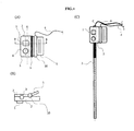
Next, the first embodiment will be described with reference to FIGS. 1 to 6 and 8. FIG. 1 shows an exemplary medical guidance device. The medical guidance device of this embodiment includes an
角度センサ1内の慣性測定ユニットは、ジャイロスコープ、加速度計および磁力計のうちの1つまたは複数を有し、いくつかの好ましい実施形態では、ジャイロスコープ、加速度計および磁力計が、それぞれ、高い頻度での向きの感知と向きの正確な感知との組合せを提供することができる。これらのジャイロスコープ、加速度計および磁力計は、統合された出力を有する単一のチップ上に組み込まれていてもよく、または別々に配置されていてもよい。慣性測定ユニットは、手術に長期間使用する間の感知された向きのドリフトを低減させることも可能にする。したがって、医師または他の医療専門家は、手術を通して、手動操作に対するリアルタイムの正確な向きで医療装置を誘導することができる。
The inertial measuring unit in the
ツールガイド3を用いて機械的インタフェース2を挿入可能医療ツール7に取り付けたり、取り外したりすることができる(図1(C))。軸Aは、ツールガイド3の中心線であり、取付けモードでは、軸Aが、挿入可能医療ツール7の重心である軸Cと整列する。さらに、角度センサ1は、ツールガイド3に対する設計された(既知の)幾何学的関係で機械的インタフェース2上に固定されており、この設計された幾何学的関係を使用することによって、角度センサ1は、挿入可能医療ツール7に対する角度センサ1の回転関係を、角度センサ1の座標系に対して位置合わせすることができる。角度センサ1は、既知の幾何学的関係で、機械的インタフェース2に直接にまたは間接的に取り付けることができる。
The
この実施形態では、挿入可能医療ツール7が長い針状の装置として示されている。しかしながら、本発明では、他のフォームファクタ(form factor)を有する中間ツールを使用することもできる。 In this embodiment, the insertable medical tool 7 is shown as a long needle-like device. However, in the present invention, intermediate tools having other form factors can also be used.
この取付け特徴のため、この例示的な医療ガイダンス装置の機械的インタフェース2は、ハンドル5、ヒンジ10を含む。
Due to this mounting feature, the
図8は、この取付け機能の詳細な原理を示す。この実施形態の機械的インタフェース2は、ヒンジ10のばね20を用いて、挿入可能医療ツール7を保持する(図8(A)の線K−Kで切った断面図としての図8(B))。医療専門家は、例えばハンドル5を押してツールガイド3を開くことができ、軸Jに沿ってツールガイド3を挿入可能医療ツール7に取り付ける。任意選択で、ツールガイド3の中心線Kと挿入可能医療ツール7の重心とを整列させる。
FIG. 8 shows the detailed principle of this mounting function. The
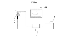
図2は、この実施形態のブロック図を示す。医療ガイダンス装置11は、信号インタフェース12を介してコンソール13に電気的に接続されている。この接続は、また、角度センサ1に電力を供給する。コンソール13は、さらに、表示器14および画像サーバ15に接続されている。コンソール13は、画像サーバ15から医用画像、例えばCT画像またはMRI画像を受け取る。画像サーバ15は、例えば、医用画像化装置に接続されたDISCOMサーバである。それらの医用画像は、また、医師または他の医療専門家がコンソール13によって医療手技を計画するのを助ける注釈付きの情報とともに、表示器14に送られる。
FIG. 2 shows a block diagram of this embodiment. The
また、医用画像を用いて基準向きを規定するために医療専門家と対話するように、コンソール13を適合させることもできる。この基準向きは、信号インタフェース12を介して医療ガイダンス装置11に送られる。例えば、計画策定中、医療専門家は、1つまたは複数の医用画像を見た後に基準向きを規定することができる。2回以上の配置(例えば針の多数回の配置)を必要とする手技に対しては、いくつかの基準向きを規定することができる。この情報を医療ガイダンス装置に送ることができ、医療ガイダンス装置は、医療ガイダンス装置に取り付けられた挿入可能医療ツールを医療専門家が移動させるときに、1種または数種のフィードバックを提供することによって、医療専門家を支援する。
The
医療ガイダンス装置11は、また、医療ガイダンス装置11の座標に基づく医用画像の位置合わせされた回転を使用することによって、基準向きと挿入可能医療ツール7の向きとの間の差を決定することができる。信号インタフェースは、回路基板が、挿入可能医療ツールのリアルタイムの向きを標的の向きと比較すること、およびそれらの向き間の差を評価することを可能にする。回路基板は、後に論じるようなコンピュータ内で一般的に見られるコントローラまたは他の特徴の組合せとすることができる。したがって、医療専門家は、計画と実行との間の差を低減させる手技を実行することができる。この差は、例えば、この差の相対量を示す画像または信号として表示器14上に表示することができる。この信号は、ビープ音、振動または光などとすることができる。このフィードバックは、リアルタイムで提供することができる。
The
回路基板をデータ記憶ユニットに接続することができる。このデータ記憶ユニットは、基準向きおよび/または挿入可能医療ツールの向きを記憶する。データ記憶ユニットによって記憶された向きを使用して、例えば、異なる時点におけるこれらの向き間の類似性または差を評価することができる。この類似性または差を用いて、医療専門家は、以前の手術または現在の手術を分析することができ、手術を改良または再現するために手術を計画することもできる。医療専門家が関心を寄せる基準向きを記憶することによって、医療ガイダンス装置は、基準向きとリアルタイムの向きとの間の差を評価することができる。この差を用いて、医療専門家は、医療専門家が関心を寄せる基準向きとある関係にある向きに医療装置を向けることができ、または基準向きと同じ向きを迅速かつ正確に再現することができる。基準向きは、同じ挿入可能医療ツールを最後に挿入したときの角度とすることができ、または、医師もしくは他の医療専門家が多数の挿入可能医療ツールをその患者に挿入するときには、直前の挿入可能医療ツールの挿入角度とすることができる。 The circuit board can be connected to the data storage unit. This data storage unit stores the reference orientation and / or the orientation of the insertable medical tool. The orientations stored by the data storage unit can be used, for example, to assess similarities or differences between these orientations at different time points. Using this similarity or difference, medical professionals can analyze previous or current surgery and can also plan surgery to improve or reproduce surgery. By memorizing the reference orientation of interest to the medical professional, the medical guidance device can assess the difference between the reference orientation and the real-time orientation. This difference can be used by a healthcare professional to orient a medical device in a direction that is in a relationship with the reference orientation of interest to the healthcare professional, or to quickly and accurately reproduce the same orientation as the reference orientation. can. The reference orientation can be the angle at which the same insertable medical tool was last inserted, or just before insertion when a doctor or other healthcare professional inserts a large number of insertable medical tools into the patient. It can be the insertion angle of possible medical tools.
また、医療専門家は基準向きを迅速に更新することができるため、このシステムは、角度センサ1の向きの誤差、特に長期間のドリフト誤差を低減させることができる。医療専門家は、基準向きを更新した後のある短い期間のうちにリアルタイムの向きの情報を使用することができる。
Also, since the medical professional can quickly update the reference orientation, the system can reduce the orientation error of the
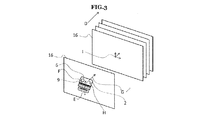
図3は、医用画像と医療ガイダンス装置11との間の回転を位置合わせする方法のうちの1つの方法を示す。この例示的な位置合わせでは、医療ガイダンス装置11を医療手技に実際に使用する前に、医療専門家が、医療ガイダンス装置11を保持し、医療ガイダンス装置11を画像平面方向Dに向ける。機械的インタフェース2上の基準マーカ9は、細線(hair line)であり、基準マーカ9は、画像平面16の方向に整列している。この実施形態では、CTまたはMRIなどの医用画像化装置が、医用画像化装置の頂部からレーザ線を投影することによって、画像平面位置に線を提供する。基準マーカ9は、手動でその線に整列される。医療専門家は、例えばボタン9を約1秒間押し続けることによって、この整列の完了を医療ガイダンス装置11に知らせることができる。
FIG. 3 shows one of the methods of aligning the rotation between the medical image and the
次いで、加速度計を使用することによって、医療ガイダンス装置11が重力の方向Eを測定する。また、医療ガイダンス装置11は、既に、基準マーカ9の細線に対して垂直方向である方向Fを知っている。したがって、医用画像平面16の座標系Iの3軸のうちの1軸、すなわち医用画像平面16が重力方向Eを含むと仮定すると、医療ガイダンス装置11は、医療ガイダンス装置11の座標Hに基づいて医用画像向きGを決定することができる。したがって、医療ガイダンス装置11は、医用画像平面16の回転をその座標系に位置合わせすることができる。
The
図4は、この回転位置合わせのために患者に装着される別の医療ガイダンス装置11である。この実施形態の機械的インタフェース2は、例えば、患者の皮膚に接着することができる接着剤とすることができる。また、機械的インタフェース2は、医療専門家が医療手技のために使用する医用画像化様式(modality)で見ることができる2つの位置合わせマーカを含む。
FIG. 4 is another
最初に、患者および挿入可能医療ツール7に取り付ける2つの医療ガイダンス装置11を、同じ座標系に対して互いに位置合わせする。この位置合わせは、機械的な撓み(mechanical flexure)を使用することによって実行することができる。この機械的な撓みは、2つの医療ガイダンス装置11を同じ方向に正確に整列させる。この位置を用いて、2つの医療ガイダンス装置11は、向きを測定することができ、それらの向きをコンソール13内の処理装置に送る。コンソール13内の処理装置は、2つの向き間の誤差を較正する。
First, the patient and the two
次に、医療専門家は、位置合わせマーカ17を含む医療ガイダンス装置11を患者の皮膚に装着し、位置合わせマーカ17を含む患者の医用画像を撮影する。それらの医用画像は、コンソール13に送られる。次いで、コンソール13が、患者の医用画像の回転と医療ガイダンス装置11との間の画像位置合わせを、位置合わせマーカ17の画像を使用することによって実行する。
Next, the medical specialist attaches the
患者上の医療ガイダンス装置11と挿入可能医療ツール7上の医療ガイダンス装置11との間の回転は較正されているため、挿入可能医療ツール7上の医療ガイダンス装置11も、医用画像平面16の回転に対して位置合わせされている。
Since the rotation between the
この例では2つの基準マーカ17を提供しているが、本発明は、2つの位置合わせマーカ17だけに限定されない。任意の数、向きまたはタイプの基準マーカまたはその他のマーカを使用して、医療装置11および/または挿入可能医療ツール7を較正および/または位置合わせすることができる。
Although two
図5は、医用画像の座標を示し、3D空間における向きを、挿入可能医療ツール7を点Oにおいて患者に挿入することを伴う医療手技に使用するために特定の2つの角度にどのようにマップするかが説明される。Y軸は、画像スキャン方向Dを向いており、X軸およびZ軸は、医用画像の平面16上にある。原点Oは、挿入可能医療ツール7の皮膚進入点に位置する。挿入可能医療ツール7は、患者の体内に挿入するための針状のツールである。
FIG. 5 shows the coordinates of the medical image and how the orientation in 3D space is mapped to two specific angles for use in a medical procedure involving inserting the insertable medical tool 7 into the patient at point O. Explain how to do it. The Y-axis points in the image scanning direction D, and the X-axis and Z-axis are on the
図5(A)では、ツールの向き17が、X−Z平面の医用画像平面に対して傾いており、ツールの向き17は、挿入前に医師が挿入可能医療ツールを置く初期位置を示す。医療ガイダンス装置11は、3D空間におけるツールの向き17を、挿入平面方向φ、挿入角度θおよびツールの回転ωにマップする。挿入平面方向φは、画像平面と挿入平面との間の関係を知らせる。医療専門家が、画像平面上で針状のツールを挿入する必要があるとき、医療専門家はツールを移動させ、ツールの向き17がφ=0である画像平面上にあるかどうかを確認することができる(図5(B))。また、挿入角度θが、挿入平面方向φとともに挿入の向きを決定した。さらに、挿入可能医療ツール7上の特徴、例えば針状の装置の斜端および内視鏡装置のカメラの向きを確認するため、医療ガイダンス装置11は、ツールの回転ωを提供することができる。
In FIG. 5 (A), the
図6では、医療ガイダンス装置11が、ツールの向き17と基準向き18との間の差を計算することができる。この差は、ツールの向き17と基準向き18との間の角度の誤差ノルム(error norm)とすることができる。この差は、ツールの向き17と基準向き18との間の相対的な向きとすることもできる。
In FIG. 6, the
いくつかの実施形態では、ケーブル4が無線接続で置き換えられる。
In some embodiments, the
医療ガイダンス装置11は、また、許容向き(tolerance orientation)19を含むことができる。許容向き19は、挿入の必要精度を規定する。許容向き19を用いて、医療ガイダンス装置は、ツールの向き17が許容範囲内にあるかどうかのフィードバックを、表示器14を使用することによって与えることができる。
The
(実施形態2)
次に、図7、図9および図10を参照して第2の実施形態を説明する。第1の実施形態の構成要素と同様の構成要素は同じ参照符号によって示されており、したがってそれらの構成要素の説明は省く。この実施形態は、特に、機械的インタフェース2が第1の実施形態とは異なる。
(Embodiment 2)
Next, a second embodiment will be described with reference to FIGS. 7, 9 and 10. Components similar to the components of the first embodiment are indicated by the same reference numerals, and therefore description of those components is omitted. This embodiment is particularly different from the first embodiment in that the
図7は、この実施形態の機械的インタフェース2を示す。機械的インタフェース2は、ツールガイド3を含むスナップクリップ21を有する。スナップクリップ21は、追加のヒンジおよびハンドルがない小さなフットプリントの機械的インタフェース2を可能にする。より軽量のガイダンス装置を可能にすることができるため、このことは特に有利である。いくつかの実施形態は、医療ガイダンス装置を針上に配置する必要があるため、軽量の装置は重要である。これは、重量または均等でない重量分布のために挿入可能医療ツール7の保持および移動が困難になることがないためである。
FIG. 7 shows the
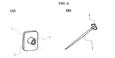
代替として、図9に、別の例示的な機械的インタフェース2が示されている。機械的インタフェース2は、ツールガイド3を含むキャップ特徴を有する。この構成は、挿入可能医療ツール7の遠位端に機械的インタフェース2を装着することによって、保持および挿入に使用できる挿入可能医療ツール7の長さを最大にする。
As an alternative, FIG. 9 shows another exemplary
図10は、この実施形態のさらに別の機械的インタフェース2を示す。機械的インタフェース2は、医師または他の医療専門家の手22に装着するフィンガキャップを有する。
FIG. 10 shows yet another
(実施形態3)
次に、図11および図12を参照して第3の実施形態を説明する。第1の実施形態の構成要素と同様の構成要素は同じ参照符号によって示されており、したがってそれらの構成要素の説明は省く。第1の実施形態と異なる主な特徴は、表示器14である。
(Embodiment 3)
Next, a third embodiment will be described with reference to FIGS. 11 and 12. Components similar to the components of the first embodiment are indicated by the same reference numerals, and therefore description of those components is omitted. The main feature different from the first embodiment is the
図11の本実施形態の表示器14は、患者の皮膚進入点23の周囲に装着することができる。この表示器は、円の形状に沿った多色LED24を含む。任意選択で、基準マーカ9および矢印マーカ25を使用することによって、表示器14を、画像スキャン方向Dと整列させることができる。多色LED24は、LED位置の比較的粗い間隔で、ツールの向き17の挿入平面方向のフィードバックをリアルタイムで与え、LEDの色を変化させることによってツールの向き17と基準向き18との間の誤差ノルムを示す。
The
表示器14は、また、異なる色を発しているLEDの位置によって、基準向きの挿入平面方向を示すことができる。
The
図12(A)および図12(B)は、この実施形態の別の表示器14を示す。表示器14は、タッチスクリーンディスプレイ26およびスタンド27を有し、ベッドまたは患者に装着することができる。タッチスクリーンディスプレイは、ツールの向き17および基準向き18を示し、医療ガイダンス装置11に対するユーザインタフェースとして、医療専門家と相互作用することもできる。
12 (A) and 12 (B) show another
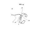
図13は、この実施形態のさらに別の表示器14である。表示器14は、医療専門家の手首に装着する第2の機械的インタフェースとしてブレスレット29を含む。表示器14は、多色LED24の色の変化、および振動によっても、基準向きとツールの向きとの間の誤差ノルムを示すことができる。この振動では、バイブレータ29の振動の振幅またはパターンが変化する。インタフェース14は、また、医療専門家からの対話を受け取るためのボタン6または他の入力手段を含む。ボタン6は、複数のボタンとすることができる。
FIG. 13 is still another
さらに別の実施形態では、例えば図9に示された機械的インタフェースなどの機械的インタフェース2の頂部に表示器14が配置される。さらに別の実施形態では、2つ以上の表示器が提供される。例えば、機械的インタフェースに取り付けられた表示器であって、医療ガイダンス装置2、挿入可能医療ツール7または機械的インタフェース2を保持しているときに感じる振動を提供する表示器とともに、図11の表示器と同様の円形のLED表示器を提供することができる。
In yet another embodiment, the
表示器は、向きの情報のリアルタイムフィードバックを医療専門家に与えることができる。医療専門家は、例えば挿入可能医療ツールを動かしたのとほぼ同時にまたは挿入可能医療ツールを動かしてから少なくとも1秒以内にフィードバックを受け取り、次いで現在の向きを直観的かつ対話的に理解し、挿入可能医療ツールを正確に誘導することができる。上述したように、このフィードバックは、用途に応じて、ならびに手技中に医療専門家がアクセスする情報の他のタイプおよびモードに応じて、視覚的なもの(画像または例えば光の強度または色の変化)、聴覚的なもの、または小振動によるものとすることができる。 The display can provide the medical professional with real-time feedback of orientation information. Health professionals receive feedback, for example, at about the same time they move the insertable medical tool or within at least one second after moving the insertable medical tool, and then intuitively and interactively understand and insert the current orientation. Possible medical tools can be guided accurately. As mentioned above, this feedback is visual (image or eg light intensity or color change) depending on the application and other types and modes of information accessed by the medical professional during the procedure. ), Auditory, or due to small vibrations.
表示器および医療ガイダンスツールをシステム内に有することによって、このシステムは、挿入可能医療ツールを誘導するための追加のシステム構成要素を必要としない。例えば、電磁追跡装置を備えるシステムでは電磁場発生装置を必要とせず、または光学追跡装置を備えるシステムでは観察カメラおよび光学マーカを必要としない。したがって、このシステムは、使用する空間およびセットアップするステップを低減させることができる。または、このシステムは、システムの組立ておよびセットアップに起因するヒューマンファクタ誤差を低減させることができる。さらに、このシステムは、システムをセットアップする時間を短縮することができる。 By having an indicator and medical guidance tools in the system, the system does not require additional system components to guide insertable medical tools. For example, a system with an electromagnetic tracking device does not require an electromagnetic field generator, or a system with an optical tracking device does not require an observation camera and an optical marker. Therefore, the system can reduce the space used and the steps to set up. Alternatively, the system can reduce human factor errors due to system assembly and setup. In addition, the system can reduce the time it takes to set up the system.
表示器を患者に装着することによって、医療専門家は、医療手技のエリアの近くで表示器を見ることができ、表示器と挿入可能医療ツールの間で眼を大きく動かさなくて済む。いくつかの実施形態では、表示器が、針状の装置の皮膚進入点を取り囲み、または部分的に取り囲み、皮膚進入点の周囲の軌道に沿ってピボットとして向きを示すことができる。医療専門家は、この表示を容易に確認し、針状の装置の基準向きに対してリアルタイムの向きを一致させることができる。医療専門家は、誘導中、表示器と針状の装置との間で視線を変化させる必要がない。 By attaching the indicator to the patient, the medical professional can see the indicator near the area of the medical procedure without having to move the eye significantly between the indicator and the insertable medical tool. In some embodiments, the indicator can surround or partially surround the skin entry point of the needle-like device and orient as a pivot along the trajectory around the skin entry point. The medical professional can easily check this display and match the real-time orientation with respect to the reference orientation of the needle-shaped device. The medical professional does not need to change the line of sight between the indicator and the needle-like device during guidance.
表示器をベッドに装着することによって、または同様に表示器を患者の近くに装着することによって、患者の無菌フィールドからは離れているが、医療専門家が表示を確認するのには十分に近い位置に、表示器を配置することができる。したがって、挿入部位の周囲の無菌フィールドを破壊する恐れなく表示器を配置することができる。また、ベッドの安定した表面によって表示器を安定して装着することもできる。 By attaching the indicator to the bed, or similarly by attaching the indicator close to the patient, it is away from the patient's sterile field, but close enough for the medical professional to see the indication. A display can be placed at the position. Therefore, the indicator can be placed without fear of destroying the sterile field around the insertion site. In addition, the stable surface of the bed allows the display to be stably attached.
他の実施形態では、医師または他の医療専門家に表示器が装着される。表示器を医療専門家に装着することによって、患者上の空間およびベッド上の空間を表示器が占有する必要がなくなる。また、この表示器は、常に医療専門家の近くに置くことができる。さらに、この表示器は、主として投薬の際の関心の部位の近くに位置する他の挿入可能医療ツールから離れているため、ケーブルのもつれを回避することができる。このことは、さらに、医療専門家への視覚的フィードバックの代わりに触覚的フィードバックを可能にする。 In other embodiments, the indicator is worn by a physician or other healthcare professional. By attaching the indicator to the medical professional, the indicator does not have to occupy the space above the patient and the space above the bed. Also, this indicator can always be placed near a medical professional. In addition, the indicator is away from other insertable medical tools located primarily near the site of interest during dosing, thus avoiding cable entanglement. This also allows tactile feedback instead of visual feedback to medical professionals.
いくつかの実施形態では、2つ以上の表示器が存在する。関連表示器をさまざまな位置および角度に装着することを可能にする第2の機械的インタフェースまたはさらなる機械的インタフェースが存在してもよい。したがって、例えば挿入可能医療ツールまたは患者に沿ったさまざまな角度または位置のうち医療専門家のニーズに最も合う1つの角度または位置に表示器を取り付けることによって、医療専門家は、医療専門家のニーズに応じた表示器の最適な表示を得ることができる。さらに、医療専門家は、異なる医療専門家の間で多数の表示器を使用することができ、異なる医療専門家の間でリアルタイムの向きを共有することができる。 In some embodiments, there are two or more indicators. There may be a second mechanical interface or additional mechanical interface that allows the associated indicator to be mounted at different positions and angles. Thus, for example, by attaching the indicator to an insertable medical tool or at one of the various angles or positions along the patient that best suits the needs of the medical professional, the medical professional can meet the needs of the medical professional. It is possible to obtain the optimum display of the display according to the above. In addition, medical professionals can use multiple indicators among different medical professionals and share real-time orientations between different medical professionals.
(実施形態4)
次に、図14および図15を参照して第4の実施形態を説明する。第1の実施形態の構成要素と同様の構成要素は同じ参照符号によって示されており、したがってそれらの構成要素の説明は省く。第1の実施形態と異なる主な特徴は、機械的インタフェース2およびツールガイド3である。
(Embodiment 4)
Next, a fourth embodiment will be described with reference to FIGS. 14 and 15. Components similar to the components of the first embodiment are indicated by the same reference numerals, and therefore description of those components is omitted. The main features different from the first embodiment are the
図14は、例示的な医療ガイダンス装置11を示し、この実施形態では、医療ガイダンス装置11が、機械的インタフェース2Aおよび2Bならびにツールガイド3Aおよび3Bを備える。図14は、医療ガイダンス装置11の分解図である。この実施形態では、医療ガイダンス装置11が、1人の患者用の装置であり、治療後に廃棄可能である。角度センサ1は、底部ハウジング31および頂部ハウジング32によって収容されており、電池30によって電力が供給される。電池30は、また、無線通信モジュール34ならびに回路基板33の全ての電子部品に電力を供給する。底部ハウジングおよび頂部ハウジング31、32は、機械的インタフェース2Aおよび2Bを有する。機械的インタフェース2Aおよび2Bは、ツールガイド3Aおよび3Bとして貫通穴を含む。これらのツールガイド3Aおよび3Bは、互いに同心であり、角度センサ1の座標系のデフォルト軸の1つとして規定された同じ軸を共有している。回路基板33は、また、ツールガイド3Aからツールガイド3Bに至る通路を形成する貫通穴を有する。この通路に挿入可能医療ツール7を嵌合させる。
FIG. 14 shows an exemplary
図15は、例示的な医療ガイダンス装置11と挿入可能医療ツール7の組立品の側面図である。この実施形態の挿入可能医療ツール7は、軟部組織を切除する切除プローブである。医療ガイダンス装置11は、挿入可能医療ツール7の針状のプローブ部分の近位端に取り付けられている。医療専門家は、挿入可能医療ツール7を治療に使用する前に、ツールガイド3Aおよび3Bに医療ガイダンス装置11を取り付けることができる。ツールガイド3Aおよび3Bは、針状プローブ部分と接触し、針状プローブの向きを、ツールガイド3Aおよび3Bの軸と整列させる。ツールガイド3Aおよび3Bは、針状プローブに対する適当な機械的コンプライアンス(mechanical compliance)および摩擦を有し、針状プローブの所望の位置に医療ガイダンス装置11を保持することができる。
FIG. 15 is a side view of an assembly of an exemplary
針状プローブ部分のゲージ(直径)の周囲にぴったりとはまる適当な直径を有するように、ツールガイド3Aおよび3Bを構成および設計することができる。ツールガイド3Aおよび3Bを針状プローブ部分に取り付けることによって、医療ガイダンス装置11は、針状プローブ部分のゲージが同じさまざまな異なる挿入可能医療ツール7に適合することができる。したがって、医療ガイダンス装置11は、針状プローブ部分を有する広範囲にわたる挿入可能医療ツール7に適合することができる。さらに、ゲージの異なる針状プローブに適合するため、ツールガイド3Aおよび3Bは、ゲージ管(gauge tube)を含むこともできる。その結果、ツールガイド3Aおよび3Bは、同じツールガイド3Aおよび3Bを有する異なるゲージに適合することができる。また、ゲージ管は、医療ガイダンス装置11の内側を環境から密封することができ、動作不良および汚染を防ぐことができる。
Tool guides 3A and 3B can be configured and designed to have a suitable diameter that fits snugly around the gauge (diameter) of the needle probe portion. By attaching the tool guides 3A and 3B to the needle probe portion, the
(応用)
使用時、医療ガイダンス装置は、挿入可能医療ツールまたは医療専門家の手のリアルタイムの向きを直接に提供する。したがって、この装置は、挿入可能医療ツールまたは医療専門家の手が最初の向きから移動しているときまたは位置を変えているときの向きの誤差を低減させまたは排除することができる。また、この装置は、任意の軌道を通した任意の位置における標的向きに対する挿入可能医療ツールの向きの柔軟性を提供することができる。さらに、医療専門家は、リアルタイムの向きを使用することによって、手術中に向きを絶え間なく調整することができる。例えば、医療専門家は、挿入中に針状の装置の向きを調整することができる。
(application)
When in use, the medical guidance device directly provides an insertable medical tool or real-time orientation of the medical professional's hand. Thus, the device can reduce or eliminate orientation errors when the insertable medical tool or medical professional's hand is moving or repositioning from the initial orientation. The device can also provide the flexibility of the orientation of the insertable medical tool with respect to the target orientation at any position through any trajectory. In addition, medical professionals can use real-time orientation to constantly adjust orientation during surgery. For example, a medical professional can adjust the orientation of the needle-like device during insertion.
振動付きで使用されるとき、この装置は、また、視覚的な合図の代わりに振動を使用することによって、医療専門家が位置を決定することまたは位置を維持することを可能にすることができ、したがって、医療専門家が、異なる方向を見ている間に医療ガイダンス装置を潜在的に使用することを可能にすることができる。 When used with vibration, the device can also allow medical professionals to position or maintain position by using vibration instead of visual cues. Therefore, it can allow medical professionals to potentially use the medical guidance device while looking in different directions.
さらに、この医療ガイダンス装置は、挿入可能医療ツールまたは医療専門家の手に機械的インタフェースを取り付けることによって、既存の医療ツールを含むさまざまな挿入可能医療ツールを誘導することを可能にする。したがって、リアルタイムの向き検出に関連して、医療専門家は、挿入可能医療ツールの向きを定める既存のワークフローを、最小限の変更で実行することができる。また、挿入可能医療ツールまたは医療専門家の手から医療ガイダンス装置を取り外すことによって、医療専門家は、挿入可能医療ツールの構成を容易かつ迅速に変更することができ、この構成は、誘導する挿入可能医療ツールのタイプまたは特性、医療ガイダンス装置の数、医療ガイダンス装置を取り付ける位置、およびワークフローを実施する場所であり、所望のワークフローを実行することができる。 In addition, this medical guidance device makes it possible to guide a variety of insertable medical tools, including existing medical tools, by attaching a mechanical interface to the insertable medical tool or the hand of a medical professional. Thus, in relation to real-time orientation detection, medical professionals can perform existing workflows for orienting insertable medical tools with minimal modification. Also, by removing the medical guidance device from the insertable medical tool or the medical professional's hand, the medical professional can easily and quickly change the configuration of the insertable medical tool, which is a guiding insertion. Possible types or characteristics of medical tools, number of medical guidance devices, location to install medical guidance devices, and place to perform the workflow, which can perform the desired workflow.
また、慣性測定ユニットを使用することにより、医療装置の向きを外部から観察して3次元空間における向きを決定する構成要素をこの装置が含む必要がなくなる。したがって、この装置を小型化することができ、この装置は、医師または他の医療専門家の動線(line of flow)および視線を遮ることを回避することができる。また、制限された空間で、例えば医用画像化装置のボアの内側でまたは手術室内の他の医療装置の間の空間でこの装置を使用することができる。 Further, by using the inertial measurement unit, it is not necessary for the device to include a component for observing the direction of the medical device from the outside and determining the direction in the three-dimensional space. Therefore, the device can be miniaturized and the device can avoid obstructing the line of flow and line of sight of a doctor or other medical professional. The device can also be used in confined spaces, such as inside the bore of a medical imaging device or between other medical devices in the operating room.
いくつかの用途では、基準センサに追加の基準装置が取外し可能に取り付けられる。この基準装置は、例えば患者に取り付けられ、または標的点に挿入される(すなわち治療する病変に針が挿入される)。次いで、基準装置上の基準センサと、挿入可能医療ツール(標的点に誘導され、次いで標的点に挿入されるツール)上の残りの角度センサとの間の差が、医療専門家が関心を寄せる任意の基準から挿入可能医療ツールを誘導することに使用できる。この基準を使用して、呼吸するたびに動く患者の胸などの例示的な動的物体を分析することができる。ガイダンス装置、センサおよび呼吸している患者の体表をこの基準とすることができる。この例示的な実施形態および他の実施形態では、このセンサが超音波プローブである。したがって、医療専門家は、誘導の際の動的運動を考慮して、挿入可能医療ツールの誘導を計画および実行することができる。 In some applications, an additional reference device is detachably attached to the reference sensor. The reference device is attached, for example, to the patient or inserted at the target point (ie, the needle is inserted into the lesion to be treated). Then, a reference sensor on the reference device, inserted medical tool difference between the remaining angle sensor on (induced in the target point, then the tool is inserted into the target point), medical professional interest It can be used to guide insertable medical tools from any criteria. This criterion can be used to analyze exemplary dynamic objects such as the patient's chest that move with each breath. Guidance devices, sensors and the body surface of the breathing patient can be used as this reference. In this exemplary embodiment and other embodiments, the sensor is an ultrasonic probe. Therefore, the medical professional can plan and execute the guidance of the insertable medical tool in consideration of the dynamic movement during the guidance.
いくつかの用途では、患者または患者の近くに取り付けられた基準センサが、挿入可能医療ツールを誘導するために、患者の動き、例えばベッドでの寝返り、呼吸、心拍動を考慮することができる。超音波画像化プローブ上に置かれた基準センサは、医療ガイダンス装置の向きを超音波画像の座標に位置合わせすることができ、また、リアルタイム超音波画像に関連づけられたリアルタイムの向きを用いて挿入可能医療ツールを誘導することができる。 In some applications, a reference sensor mounted on or near the patient can take into account the patient's movements, such as turning over in bed, breathing, and heartbeat, to guide the insertable medical tool. A reference sensor placed on the ultrasound imaging probe can align the orientation of the medical guidance device to the coordinates of the ultrasound image and also insert using the real-time orientation associated with the real-time ultrasound image. Possible medical tools can be guided.
皮膚進入点の位置を医用画像の座標に位置合わせすることによって、このシステムは、また、医療装置の軌道が向かう点を規定することができる。医療ガイダンス装置からの向きを用いて、コンソールは、医用画像に関連づけられた、挿入可能医療ツールの潜在的軌道のフィードバックを与えることができる。したがって、医療専門家は、解剖学的データを用いて軌道を評価することができる。 By aligning the position of the skin entry point to the coordinates of the medical image, the system can also define the point to which the trajectory of the medical device is headed. Using the orientation from the medical guidance device, the console can provide feedback on the potential trajectory of the insertable medical tool associated with the medical image. Therefore, medical professionals can use anatomical data to assess orbits.
いくつかの実施形態では、この装置が、切除療法中など多数の針の挿入時に特に有用である。医療専門家は、しばしば、患者の体内に置かれた第2の針および任意の後続の針の位置決めを、最初の針の以前の配置によって規定する。したがって、使用時、最初の針を配置した後に、例えば、最初に置かれた針と実質的に同じ位置に機械的インタフェースがある間にボタン(例えば図3に示されたようなボタン9)を約1秒間押し続けることなどによって、機械的インタフェースを最初の針と整列させることができる。次いで、最初の針のこの相対位置情報に基づいて、2番目の針およびいかなる任意選択の追加の針も配置することができる。他の実施形態では、最初に置かれた針上に表示器を位置決めして、最初の針の位置情報に対する2番目の針または後続の針の向きを表示することができる。いくつかの実施形態では、本明細書に記載されたような方法によって最初の針が配置され、他の実施形態では、針位置決め装置を使用することによって最初の針が配置される。
In some embodiments, this device is particularly useful when inserting a large number of needles, such as during resection therapy. Medical professionals often define the positioning of the second needle and any subsequent needle placed in the patient's body by the previous placement of the first needle. Thus, during use, after placing the first needle, for example, while the mechanical interface is in substantially the same position as the first needle placed, a button (eg,
本明細書に開示されたような装置および方法を、米国特許出願公開第2014/0275979号に開示された装置などの針位置決め装置と組み合わせて使用することもできる。この米国特許出願公開は、その全体が参照によって本明細書に組み込まれている。 Devices and methods as disclosed herein can also be used in combination with needle positioning devices such as those disclosed in US Patent Application Publication No. 2014/0275979. This US patent application publication is incorporated herein by reference in its entirety.
ソフトウェアに関する開示
回路基板、コンソール13、画像サーバ15および任意選択で表示器14のうちの1つまたは複数を備える本発明の実施形態は、記憶媒体上に記録されたコンピュータ実行可能命令(例えば1つまたは複数のプログラム)を読み出し、実行して、前述の実施形態のうちの1つもしくは複数の実施形態の機能を実行する1つもしくは複数のコンピュータ、および/または前述の実施形態のうちの1つもしくは複数の実施形態の機能を実行する1つもしくは複数の回路を含む1つもしくは複数のコンピュータによって実現することができ、また、例えばコンピュータ実行可能命令を記憶媒体から読み出し、実行して、前述の実施形態のうちの1つもしくは複数の機能を実行することにより、および/または前述の実施形態のうちの1つもしくは複数の機能を実行するように1つもしくは複数の回路を制御することによりこのシステムまたは装置のコンピュータによって実行される方法によって実現することができる。
Software Disclosure An embodiment of the invention comprising one or more of a circuit board, a
例示的なコンピュータユニットCUの詳細を説明する。コンピュータシステムは、CPU、記憶装置/RAM、I/Oインタフェースおよびユーザインタフェースを含む。また、コンピュータシステムは、1つまたは複数の装置を備えることができる。例えば、1つのコンピュータは、CPU、記憶装置/RAM、I/Oインタフェースを含むことができ、他のコンピュータは、1つまたは複数のユーザインタフェースを含むことができる。このCPUは、記憶装置/RAMに記憶されたコンピュータ実行可能命令を読み、実行するように構成されている。これらのコンピュータ実行可能命令は、本明細書に記載された方法および/または計算を実行するためのコンピュータ実行可能命令を含むことができる。例えば、CPUは、角度センサからの情報、画像サーバからの情報、信号インタフェースからの情報などに基づいてさまざまな値を計算する。記憶装置/RAMは、コンピュータが読むことができかつ/またはコンピュータが書き込むことができる1つまたは複数の媒体を含む。記憶装置/RAMは、例えば、磁気ディスク(例えばハードディスク)、光学ディスク(例えばDVD、Blu−ray)、磁気光学ディスク、半導体メモリ(例えば不揮発性メモリーカード、フラッシュメモリ、固体ドライブ、SRAM、DRAM)、EPROM、EEPROMなどを含むことができる。記憶装置/RAMは、コンピュータ可読データおよび/またはコンピュータ実行可能命令を記憶することができる。コンピュータシステム内の構成要素は、それぞれ、バスを介して互いに通信する。例えば、画像データ、例えばCT画像またはMRI画像からの画像データ、画像サーバ15によって記憶され、送られる。この画像データは、記憶装置/RAMに記憶することができる。次いで、この画像を、医療ガイダンス装置11またはユーザ入力からの標的向きまたは標的向きからの差などの追加情報とともに、またはこのような追加の情報なしで、モニタに表示することができる。
The details of the exemplary computer unit CU will be described. The computer system includes a CPU, a storage device / RAM, an I / O interface and a user interface. Also, the computer system may include one or more devices. For example, one computer can include a CPU, storage / RAM, I / O interfaces, and the other computer can include one or more user interfaces. The CPU is configured to read and execute computer executable instructions stored in the storage device / RAM. These computer-executable instructions may include computer-executable instructions for performing the methods and / or calculations described herein. For example , the CPU calculates various values based on information from an angle sensor, information from an image server, information from a signal interface, and so on. The storage device / RAM includes one or more media that can be read and / or written by the computer. The storage device / RAM includes, for example, a magnetic disk (for example, a hard disk), an optical disk (for example, DVD, Blu-ray), a magnetic optical disk, a semiconductor memory (for example, a non-volatile memory card, a flash memory, a solid-state drive, SRAM, a DRAM), and the like. EPROM, EEPROM and the like can be included. The storage device / RAM can store computer-readable data and / or computer-executable instructions. Each component in a computer system communicates with each other via a bus. For example, image data , such as image data from a CT image or an MRI image, is stored and transmitted by the
I/Oインタフェースは、入力および出力装置に対する通信インタフェースを提供する。この入力および出力装置は、回路基板、表示器14、信号インタフェース12および画像サーバ15に加えて、通信ケーブル、ネットワーク(有線もしくは無線)または他の装置を含むことができる。このI/Oインタフェースを、キーボード、マウス、タッチスクリーン、ライトペン、マイクロホンなどのうちの1つまたは複数のユーザインタフェースユニットなどのユーザインタフェースユニットに結合することができる。
The I / O interface provides a communication interface for input and output devices. The input and output devices can include communication cables, networks (wired or wireless) or other devices, in addition to circuit boards,
定義
この説明を参照するに際しては、開示した例を完全に理解することができるように、具体的な詳細を記載した。他の例では、本開示が不必要に長くならないように、周知の方法、手順、構成要素および回路については、詳細には説明しない。
Definitions In reference to this description, specific details have been provided so that the disclosed examples can be fully understood. In other examples, well-known methods, procedures, components and circuits will not be described in detail so that the disclosure is not unnecessarily lengthy.
本明細書で、1つの要素もしくは部分が、別の要素もしくは部分「上にある」、「に当たっている」、「に接続されている」もしくは「に結合されている」と参照されている場合、その要素もしくは部分は、直接にその他の要素もしくは部分「上にあり」、「に当たっており」、「に接続されており」もしくは「に結合されている」ことができ、または介在要素もしくは介在部分が存在してもよいことを理解すべきである。反対に、1つの要素が、別の要素または部分「上に直接にある」、「に直接に接続されている」、または「に直接に結合されている」と参照されている場合、介在要素または介在部分は存在しない。用語「および/または」が使用されているとき、この用語は、記載された関連アイテムのうちの1つまたは複数のアイテムの全ての組合せを、そのように提供され場合に含む。 When one element or part is referred to herein as being "on", "hit", "connected to" or "combined with" another element or part. The element or part can be directly "on", "hit", "connected to" or "connected to" the other element or part, or the intervening element or part is It should be understood that it may exist. Conversely, if one element is referred to as another element or part "directly on", "directly connected to", or "directly connected to", the intervening element Or there is no intervening part. When the term "and / or" is used, the term includes all combinations of one or more of the related items described, if provided as such.
本明細書では、説明を容易にするため、さまざまな図に示されているような1つの要素または特徴の別の要素または特徴に対する関係を記述するために、「の下(under)」、「の下方(beneath)」、「よりも下(below)」、「下部(lower)」、「よりも上(above)」、「上部(upper)」、「近位(proximal)」、「遠位(distal)」などの空間に関する相対的な用語が使用されていることがある。しかしながら、空間に関するこれらの相対的な用語は、図に示された向きに加えて、装置の使用または操作の異なる向きを包含することが意図されていることを理解すべきである。例えば、図に示された装置が裏返された場合、他の要素または他の特徴の下方にあるまたは下にあると記載された要素は、その他の要素または特徴「よりも上」になることになる。したがって、「よりも下」などの空間に関する相対的な用語は、上と下の両方の向きを包含しうる。これとは異なる向き(90度回転させた向きまたはその他の向き)に装置が配置されることもあり、その場合、本明細書で使用される空間に関する相対的な用語は、それに応じて解釈されるべきである。同様に、空間に関する相対的な用語「近位」と「遠位」も、適用可能な場合には相互に交換可能である。 In the present specification, for ease of explanation, "under", "under", "under", "under", "under", to describe the relationship of one element or feature to another element or feature as shown in various figures. Below "beneath", "below", "lower", "above", "upper", "proximal", "distal" Relative terms related to space, such as "distal", may be used. However, it should be understood that these relative terms with respect to space are intended to include different orientations of use or operation of the device in addition to the orientations shown in the figure. For example, if the device shown in the figure is turned inside out, the other element or element described as being below or below the other feature will be "above" the other element or feature. Become. Therefore, spatial relative terms such as "below" can include both up and down orientations. The device may be placed in a different orientation (90 degree rotation or other orientation), in which case the relative terms for space used herein shall be construed accordingly. Should be. Similarly, the relative terms "proximal" and "distal" with respect to space are interchangeable, where applicable.
本明細書で使用されているとき、用語「約」は、例えば10%以内、5%以内または5%未満を意味する。いくつかの実施形態では、用語「約」が、測定誤差以内を意味することがある。 As used herein, the term "about" means, for example, within 10%, within 5%, or less than 5%. In some embodiments, the term "about" may mean within measurement error.
本明細書では、第1の、第2の、第3のなどの用語が、さまざまな要素、構成要素、領域、部分および/またはセクションを記述するために使用されることがある。これらの用語によってこれらの要素、構成要素、領域、部分および/またはセクションが制限されるべきではないことを理解すべきである。これらの用語は、1つの要素、構成要素、領域、部分またはセクションを別の領域、部分またはセクションから区別するためだけに使用されている。したがって、以下で論じる第1の要素、構成要素、領域、部分またはセクションが、本明細書の教示から逸脱することなく、第2の要素、構成要素、領域、部分またはセクションと呼ばれることもある。 As used herein, terms such as first, second, third, etc. may be used to describe various elements, components, areas, parts and / or sections. It should be understood that these terms should not limit these elements, components, areas, parts and / or sections. These terms are used only to distinguish one element, component, area, part or section from another area, part or section. Thus, the first element, component, area, part or section discussed below may also be referred to as the second element, component, area, part or section without departing from the teachings herein.
用語「取り付けられた」は、直接取付けと(例えば間に構成要素が挟まれた)間接取付けの両方を含む。取付けは、全て、必要に応じてユーザが何回も取り付けたり取り外したりすることができるような態様の取外し可能な取付けとすることができる。取付けは、例えば医療装置が機械的インタフェースから分離しないような態様の十分な取付けであるべきである。取付けは、片手での取付けおよび/または取外しが可能なように設計することができる。 The term "attached" includes both direct attachment and indirect attachment (eg, with components sandwiched between them). All attachments can be removable in such a way that the user can attach and detach as many times as needed. The attachment should be sufficient, for example, in such a manner that the medical device does not separate from the mechanical interface. The mounting can be designed to allow one-handed mounting and / or removal.
本明細書で使用される用語は、特定の実施形態を記述することだけが目的であり、それらの用語が、特定の実施形態を限定することは意図されていない。文脈からそうではないことが明らかでない限り、本明細書で使用されるとき、単数形の「a」、「an」および「the」は、複数形も含むことが意図されている。本明細書で使用されるとき用語「含む(includes)」および/または「含んでいる(including)」は、明示された特徴、完全体(integer)、ステップ、操作、要素および/または構成要素の存在を指定するが、明示されていない1つまたは複数の他の特徴、完全体、ステップ、操作、要素、構成要素および/またはこれらのグループの存在または追加を排除しないことをさらに理解すべきである。 The terms used herein are for the purpose of describing specific embodiments only, and they are not intended to limit a particular embodiment. As used herein, the singular forms "a," "an," and "the" are intended to include the plural, unless the context makes it clear. As used herein, the terms "includes" and / or "inclusive" are of the specified features, integers, steps, operations, elements and / or components. It should be further understood that it does not preclude the existence or addition of one or more other features, perfections, steps, operations, elements, components and / or groups of these that specify existence but are not explicitly stated. be.
図面に示された例示的な実施形態を説明する際には、分かりやすくするために特定の用語が使用される。しかしながら、本特許明細書の開示が、選択された特定の用語に限定されることは意図されておらず、特定の要素は、それぞれ、同様の方式で動作する全ての技術等価物を含むことを理解すべきである。 Specific terms are used in the description of the exemplary embodiments shown in the drawings for clarity. However, the disclosure of the present patent specification is not intended to be limited to the particular term chosen, and the particular element will include all technical equivalents, each operating in a similar manner. Should be understood.
例示的な実施形態を参照して本開示を説明してきたが、本開示は、開示された例示的な実施形態だけに限定されないことを理解されたい。このような全ての変更ならびに等価の構造および機能を包含するように、以下の特許請求の範囲には、最も広い解釈が与えられる。 Although the present disclosure has been described with reference to exemplary embodiments, it should be understood that the present disclosure is not limited to the disclosed exemplary embodiments. The following claims are given the broadest interpretation to include all such modifications and equivalent structures and functions.
Claims (19)
ジャイロスコープ、加速度計または磁力計である少なくとも1つのセンサを備える慣性測定ユニット、および
前記慣性測定ユニットに接続された回路基板であって、前記慣性測定ユニットからの感知信号を処理することによって向きを計算するように構成された回路基板
を備える角度センサと、
前記角度センサに取り付けられた機械的インタフェースと、
患者に装着されるように構成され、前記皮膚進入点を少なくとも部分的に取り囲む表示器であって、
(i)前記角度センサから前記向きに関する情報を受け取り、および
(ii)前記挿入可能医療ツールの前記向きを示すことによって、医療専門家にリアルタイムのフィードバックを提供する、
ように構成された表示器と
を備え、
前記機械的インタフェースは、挿入可能医療ツールまたは医療専門家に取外し可能に取り付けられるように構成されている、
医療ガイダンス装置。 A medical guidance device configured to guide an insertable medical tool for insertion into a patient through a skin entry point.
An inertial measurement unit with at least one sensor, a gyroscope, an accelerometer or a magnetic field meter, and a circuit board connected to the inertial measurement unit, which is oriented by processing a sensing signal from the inertial measurement unit. An angle sensor with a circuit board configured to calculate,
With the mechanical interface attached to the angle sensor,
An indicator that is configured to be worn by the patient and at least partially surrounds the skin entry point.
Provide real-time feedback to the healthcare professional by (i) receiving information about the orientation from the angle sensor and (ii) indicating the orientation of the insertable medical tool.
With an indicator configured to
The mechanical interface is configured to be removable and attachable to an insertable medical tool or medical professional.
Medical guidance device.
前記回路基板は、前記ジャイロスコープ、前記加速度計および前記磁力計からの感知信号を処理することによって向きを計算するように構成された、請求項1に記載の医療ガイダンス装置。 The inertial measurement unit includes a gyroscope, an accelerometer and a magnetometer.
The medical guidance device according to claim 1, wherein the circuit board is configured to calculate orientation by processing sensing signals from the gyroscope, the accelerometer, and the magnetometer.
前記信号インタフェースは、標的向き信号を受け取るように構成されており、
前記回路基板は、前記標的向きと前記慣性測定ユニットによって決定された前記向きとの間の差を計算するように構成された、
請求項1に記載の医療ガイダンス装置。 Further provided with a signal interface connected to the circuit board
The signal interface is configured to receive a target-oriented signal.
The circuit board was configured to calculate the difference between the target orientation and the orientation determined by the inertial measurement unit.
The medical guidance device according to claim 1.
前記データ記憶ユニットは、前記慣性測定ユニットによって決定された前記向きを記憶する、
請求項1に記載の医療ガイダンス装置。 A data storage unit connected to the circuit board is further provided.
The data storage unit stores the orientation determined by the inertial measurement unit.
The medical guidance device according to claim 1.
前記回路基板は、
前記ユーザインタフェースからの前記トリガの場合の向きを基準向きとして設定し、
前記基準向きを記憶するよう前記データ記憶ユニットに指令し、
前記データ記憶ユニット内の前記基準向きと前記慣性測定ユニットによって決定された前記向きとの間の差を計算するように構成された、
請求項4に記載の医療ガイダンス装置。 Further equipped with a user interface configured to trigger the circuit board based on the operation of a medical professional.
The circuit board
The orientation in the case of the trigger from the user interface is set as the reference orientation, and the orientation is set.
Instruct the data storage unit to store the reference orientation and
It is configured to calculate the difference between the reference orientation in the data storage unit and the orientation determined by the inertial measurement unit.
The medical guidance device according to claim 4.
請求項5に記載の医療ガイダンス装置。 The reference orientation is one insertion angle of a number of insertable medical tools, and the circuit board is configured to calculate the difference between the insertion angles of different insertable medical tools and the reference orientation.
The medical guidance device according to claim 5.
前記基準マーカは、医用画像化装置の画像スキャン方向と整列しており、前記回路基板は、整列された前記1つまたは複数の基準マーカに基づいて前記基準向きを設定するように構成された、
請求項5に記載の医療ガイダンス装置。 Further provided with one or more reference markers to define the geometric relationship with the coordinates of the inertial measurement unit.
The reference marker is aligned with the image scanning direction of the medical imaging apparatus, and the circuit board is configured to set the reference orientation based on the aligned reference marker.
The medical guidance device according to claim 5.
請求項7に記載の医療ガイダンス装置。 The direction of gravity detected by the inertial measurement unit is used to determine the direction of gravity in the image.
The medical guidance device according to claim 7.
請求項1に記載の医療ガイダンス装置。 The information provided by the display is real-time feedback of orientation information.
The medical guidance device according to claim 1.
請求項1に記載の医療ガイダンス装置。 The medical guidance device was configured to guide a needle-shaped device.
The medical guidance device according to claim 1.
請求項1に記載の医療ガイダンス装置。 The indicator is mounted on the mechanical interface.
The medical guidance device according to claim 1.
前記表示器は、医療専門家によって選択された位置に取外し可能に取付け可能であるように構成された、
請求項1に記載の医療ガイダンス装置。 Further comprising a second mechanical interface mechanically connected to the indicator
The indicator is configured to be removable and mountable at a position selected by a medical professional.
The medical guidance device according to claim 1.
前記複数の医療ガイダンス装置に電気的に接続された処理装置と
を備え、
前記処理装置は、前記複数の医療ガイダンス装置のうち第1の医療ガイダンス装置の向きと他の医療ガイダンス装置の向きとの間の差を測定する、
医療ガイダンスシステム。 The plurality of medical guidance devices according to claim 1 and
A processing device electrically connected to the plurality of medical guidance devices is provided.
The processing device measures the difference between the orientation of the first medical guidance device and the orientation of the other medical guidance device among the plurality of medical guidance devices.
Medical guidance system.
前記複数の医療ガイダンス装置のうちの他の少なくとも1つの医療ガイダンス装置は、前記患者の体に挿入されるように構成された針状の装置に取り付けられた、
請求項13に記載の医療ガイダンスシステム。 The first medical guidance device is a medical guidance device provided to be attached to a patient.
At least one of the plurality of medical guidance devices is attached to a needle-shaped device configured to be inserted into the patient's body.
The medical guidance system according to claim 13.
他の医療ガイダンス装置のうちの少なくとも1つの医療ガイダンス装置は、患者の体に挿入される針状の装置に取り付けられた、
請求項13に記載の医療ガイダンスシステム。 The first medical guidance device is a medical guidance device attached to the ultrasound imaging probe,
At least one of the other medical guidance devices was attached to a needle-like device that was inserted into the patient's body.
The medical guidance system according to claim 13.
前記針状の装置が挿入される皮膚進入点に位置合わせされた患者上の位置合わせマーカと、
画像サーバおよび前記医療ガイダンス装置に電気的に接続されたコンソールと
を備え、
前記コンソールは、医用画像を受け取り、前記位置合わせマーカの位置および向きを前記患者の座標系に位置合わせし、前記コンソールは、前記皮膚進入点の位置を前記座標系に位置合わせする、
医療ガイダンスシステム。 The at least one medical guidance device according to claim 1, which is attached to a needle-shaped device.
An alignment marker on the patient aligned with the skin entry point into which the needle-like device is inserted,
It is equipped with an image server and a console electrically connected to the medical guidance device.
The console receives a medical image and aligns the position and orientation of the alignment marker with the patient's coordinate system, and the console aligns the position of the skin entry point with the coordinate system.
Medical guidance system.
前記医療ガイダンス装置は、
ジャイロスコープ、加速度計または磁力計である少なくとも1つのセンサを備える慣性測定ユニット、および
前記慣性測定ユニットに接続された回路基板であって、前記慣性測定ユニットからの感知信号を処理することによって向きを計算するように構成された回路基板
を備える角度センサと、
前記角度センサに取り付けられた機械的インタフェースと
を備え、
前記機械的インタフェースは、挿入可能医療ツールまたは医療専門家に取外し可能に取り付けられるように構成されており、
前記角度センサは、前記挿入可能医療ツールの向きを決定するように構成されており、
前記医療ガイダンス装置は、さらに、
患者に装着されるように構成された表示器であって、前記角度センサから前記向きに関する情報を受け取り、および前記挿入可能医療ツールの前記向きを示すことによって、医療専門家にリアルタイムのフィードバックを提供する、表示器
を備える、
システム。 A system equipped with a medical guidance device
The medical guidance device
An inertial measurement unit with at least one sensor, a gyroscope, an accelerometer or a magnetic field meter, and a circuit board connected to the inertial measurement unit, which is oriented by processing a sensing signal from the inertial measurement unit. An angle sensor with a circuit board configured to calculate,
With a mechanical interface attached to the angle sensor
The mechanical interface is configured to be removable and attachable to an insertable medical tool or medical professional.
The angle sensor is configured to orient the insertable medical tool.
The medical guidance device further
An indicator configured to be worn on the patient that provides real-time feedback to the healthcare professional by receiving information about the orientation from the angle sensor and indicating the orientation of the insertable medical tool. , Equipped with a display
system.
請求項1に記載の医療ガイダンス装置。 Showing the orientation of the insertable medical tool includes showing information about the insertion plane direction φ and the insertion angle θ.
The medical guidance device according to claim 1.
請求項17に記載のシステム。 Showing the orientation of the insertable medical tool includes showing information about the insertion plane direction φ and the insertion angle θ.
The system according to claim 17.
Applications Claiming Priority (3)
| Application Number | Priority Date | Filing Date | Title |
|---|---|---|---|
| US201562268378P | 2015-12-16 | 2015-12-16 | |
| US62/268,378 | 2015-12-16 | ||
| PCT/US2016/066680 WO2017106362A1 (en) | 2015-12-16 | 2016-12-14 | Medical guidance device |
Publications (3)
| Publication Number | Publication Date |
|---|---|
| JP2019508079A JP2019508079A (en) | 2019-03-28 |
| JP2019508079A5 JP2019508079A5 (en) | 2020-01-30 |
| JP6952696B2 true JP6952696B2 (en) | 2021-10-20 |
Family
ID=59057519
Family Applications (1)
| Application Number | Title | Priority Date | Filing Date |
|---|---|---|---|
| JP2018530134A Active JP6952696B2 (en) | 2015-12-16 | 2016-12-14 | Medical guidance device |
Country Status (3)
| Country | Link |
|---|---|
| US (1) | US10869613B2 (en) |
| JP (1) | JP6952696B2 (en) |
| WO (1) | WO2017106362A1 (en) |
Families Citing this family (11)
| Publication number | Priority date | Publication date | Assignee | Title |
|---|---|---|---|---|
| US20200237446A1 (en) * | 2016-10-26 | 2020-07-30 | Prichard Medical, LLC | Surgical instrument with led lighting and absolute orientation |
| WO2020219925A1 (en) * | 2019-04-26 | 2020-10-29 | Prichard Medical, LLC | Surgical instrument with led lighting and absolute orientation |
| EP3648692A1 (en) | 2017-07-07 | 2020-05-13 | Canon U.S.A. Inc. | Multiple probe ablation planning |
| US11197723B2 (en) * | 2017-10-09 | 2021-12-14 | Canon U.S.A., Inc. | Medical guidance system and method using localized insertion plane |
| US11065064B2 (en) * | 2017-11-14 | 2021-07-20 | Biosense Webster (Israel) Ltd. | Calibration of a rigid ENT tool |
| US11100633B2 (en) | 2018-06-13 | 2021-08-24 | Cosmo Artificial Intelligence—Al Limited | Systems and methods for processing real-time video from a medical image device and detecting objects in the video |
| US11707259B2 (en) | 2018-10-19 | 2023-07-25 | Canon U.S.A., Inc. | Wireless needle guidance using encoder sensor and encoder scale to achieve positional sensing between movable components |
| CN113473916A (en) * | 2019-01-30 | 2021-10-01 | 巴德阿克塞斯系统股份有限公司 | System and method for tracking medical devices |
| US20220039900A1 (en) * | 2020-08-06 | 2022-02-10 | Canon U.S.A., Inc. | Used device detection |
| US10952775B1 (en) | 2020-12-14 | 2021-03-23 | Prichard Medical, LLC | Surgical instrument with orientation sensor having a user identified heading |
| EP4052669A1 (en) * | 2021-03-04 | 2022-09-07 | 25Segments AG | Gravity-responsive inclinometer for a medical device |
Family Cites Families (39)
| Publication number | Priority date | Publication date | Assignee | Title |
|---|---|---|---|---|
| US6122538A (en) * | 1997-01-16 | 2000-09-19 | Acuson Corporation | Motion--Monitoring method and system for medical devices |
| US6226548B1 (en) * | 1997-09-24 | 2001-05-01 | Surgical Navigation Technologies, Inc. | Percutaneous registration apparatus and method for use in computer-assisted surgical navigation |
| US6132379A (en) * | 1998-11-04 | 2000-10-17 | Patacsil; Estelito G. | Method and apparatus for ultrasound guided intravenous cannulation |
| US6725080B2 (en) * | 2000-03-01 | 2004-04-20 | Surgical Navigation Technologies, Inc. | Multiple cannula image guided tool for image guided procedures |
| EP1534153B1 (en) * | 2002-09-05 | 2009-04-15 | Radi Medical Devices AB | Guide for a medical device |
| CA2589693A1 (en) * | 2004-12-10 | 2006-06-15 | Unomedical A/S | Inserter |
| CN101389284B (en) * | 2005-01-28 | 2012-07-04 | 马萨诸塞总医院 | Guidance and insertion system |
| JP2008545502A (en) * | 2005-06-10 | 2008-12-18 | コーニンクレッカ フィリップス エレクトロニクス エヌ ヴィ | System for guiding a probe across the surface of a patient or animal skin |
| US7912258B2 (en) * | 2005-09-27 | 2011-03-22 | Vanderbilt University | Method and apparatus for standardizing ultrasonography training using image to physical space registration of tomographic volumes from tracked ultrasound |
| US20070149880A1 (en) * | 2005-12-22 | 2007-06-28 | Boston Scientific Scimed, Inc. | Device and method for determining the location of a vascular opening prior to application of HIFU energy to seal the opening |
| CN100518675C (en) | 2006-01-23 | 2009-07-29 | 张惠玲 | Guiding puncture needling tool and puncture guiding method |
| US9408627B2 (en) * | 2006-03-07 | 2016-08-09 | Hirdesh SAHNI | Image guided whole body stereotactic needle placement device |
| EP2008244B1 (en) * | 2006-03-30 | 2016-04-27 | Stryker European Holdings I, LLC | System and method for optical position measurement and guidance of a rigid or semi flexible tool to a target |
| US9125676B2 (en) * | 2006-10-23 | 2015-09-08 | Hirdesh SAHNI | Image guided whole body stereotactic needle placement device with falling arc |
| US9877681B2 (en) * | 2007-03-30 | 2018-01-30 | David G. Silverman | “Micro-patch” for assessment of the local microvasculature and microcirculatory vasoreactivity |
| EP2194906B8 (en) * | 2007-09-24 | 2015-04-22 | Mri Interventions, Inc. | Mri-guided medical interventional system |
| US9521961B2 (en) * | 2007-11-26 | 2016-12-20 | C. R. Bard, Inc. | Systems and methods for guiding a medical instrument |
| US8437833B2 (en) * | 2008-10-07 | 2013-05-07 | Bard Access Systems, Inc. | Percutaneous magnetic gastrostomy |
| US8641621B2 (en) * | 2009-02-17 | 2014-02-04 | Inneroptic Technology, Inc. | Systems, methods, apparatuses, and computer-readable media for image management in image-guided medical procedures |
| EP2525731A1 (en) * | 2010-01-20 | 2012-11-28 | Creative Team Instruments Ltd. | Orientation dector for use with a hand-held surgical or dental tool |
| US8957812B1 (en) * | 2010-11-12 | 2015-02-17 | Position Imaging, Inc. | Position tracking system and method using radio signals and inertial sensing |
| CA2827589C (en) * | 2011-02-18 | 2019-07-09 | DePuy Synthes Products, LLC | Tool with integrated navigation and guidance system and related apparatus and methods |
| US9782078B2 (en) * | 2011-08-14 | 2017-10-10 | Uzi Rahum | Device, system and method for blood vessel imaging and marking |
| US20130066334A1 (en) * | 2011-09-08 | 2013-03-14 | Stryker Leibinger Gmbh & Co., Kg | Axial Surgical Trajectory Guide |
| US11395706B2 (en) * | 2012-06-21 | 2022-07-26 | Globus Medical Inc. | Surgical robot platform |
| EP2866671B1 (en) * | 2012-06-28 | 2019-10-30 | Koninklijke Philips N.V. | Ultrasonic guidance of multiple invasive devices in three dimensions |
| US9839349B2 (en) * | 2012-10-05 | 2017-12-12 | Fujifilm Corporation | Method of placing medical insertion instruments in body cavity |
| US20140276559A1 (en) * | 2013-03-12 | 2014-09-18 | Christopher Page | Devices, systems and methods for placement of instruments for medical procedures |
| US20140276001A1 (en) * | 2013-03-15 | 2014-09-18 | Queen's University At Kingston | Device and Method for Image-Guided Surgery |
| EP2967423B1 (en) * | 2013-03-15 | 2021-06-30 | Synaptive Medical Inc. | Insert imaging device for surgical procedures |
| US20150142372A1 (en) * | 2013-11-19 | 2015-05-21 | Polaris Surgical, LLC | Prosthetic placement tool and associated methods |
| US9968395B2 (en) * | 2013-12-10 | 2018-05-15 | Nxthera, Inc. | Systems and methods for treating the prostate |
| EP3205270B1 (en) * | 2014-01-29 | 2018-12-19 | Becton, Dickinson and Company | Wearable electronic device for enhancing visualization during insertion of an invasive device |
| KR102296451B1 (en) * | 2014-12-08 | 2021-09-06 | 큐렉소 주식회사 | CT-Robot Registration System for Interventional Robot |
| JP6049786B2 (en) * | 2015-03-05 | 2016-12-21 | 株式会社ミツトヨ | Measuring probe |
| US20160278746A1 (en) | 2015-03-27 | 2016-09-29 | General Electric Company | Real-time tracking for mri-guided breast biopsy |
| US9867673B2 (en) * | 2015-07-14 | 2018-01-16 | Canon U.S.A, Inc. | Medical support device |
| US10918413B2 (en) * | 2015-08-18 | 2021-02-16 | The Penn State Research Foundation | Bedside stereotactic ultrasound guidance device, system and method |
| EP3405125A1 (en) * | 2016-01-20 | 2018-11-28 | Loughborough University | Needle guides |
-
2016
- 2016-12-14 US US15/379,300 patent/US10869613B2/en active Active
- 2016-12-14 JP JP2018530134A patent/JP6952696B2/en active Active
- 2016-12-14 WO PCT/US2016/066680 patent/WO2017106362A1/en active Application Filing
Also Published As
| Publication number | Publication date |
|---|---|
| WO2017106362A1 (en) | 2017-06-22 |
| US20170172458A1 (en) | 2017-06-22 |
| US10869613B2 (en) | 2020-12-22 |
| JP2019508079A (en) | 2019-03-28 |
Similar Documents
| Publication | Publication Date | Title |
|---|---|---|
| JP6952696B2 (en) | Medical guidance device | |
| CN105662402B (en) | Needle length for being inserted into guidance system is determining and calibrates | |
| JP6438398B2 (en) | How to attach a magnetic element to a needle assembly | |
| JP2019508079A5 (en) | ||
| EP0929267B1 (en) | Image-guided surgery system | |
| US20190117317A1 (en) | Organ motion compensation | |
| US20220039876A1 (en) | Sensored surgical tool and surgical intraoperative tracking and imaging system incorporating same | |
| EP3193765B1 (en) | Processing system arranged to cooperate with an optical-shape-sensing-enabled interventional device | |
| EP1545365A1 (en) | Medical device positioning system and method | |
| EP3392835B1 (en) | Improving registration of an anatomical image with a position-tracking coordinate system based on visual proximity to bone tissue | |
| US20200197099A1 (en) | Systems, method and devices for assisting or performing guiding interventional procedures using inertial measurement units and magnetometer sensors | |
| US8067726B2 (en) | Universal instrument calibration system and method of use | |
| EP3482686B1 (en) | Calibration of a rigid ent tool | |
| US9008756B2 (en) | Mapping system and method for mapping a target containing tissue | |
| Glossop | Localization and tracking technologies for medical robotics | |
| RU2771799C2 (en) | Calibration of rigid otolaryngological instrument | |
| EP3903713A1 (en) | Field generator assembly and method for surgical navigation | |
| KR20160148326A (en) | Optical tool with patient for interventional robot system of needle guide type | |
| WO2021123958A1 (en) | Selecting cursor locations on medical image using directions from distal end of probe |
Legal Events
| Date | Code | Title | Description |
|---|---|---|---|
| A521 | Written amendment |
Free format text: JAPANESE INTERMEDIATE CODE: A523 Effective date: 20191211 |
|
| A621 | Written request for application examination |
Free format text: JAPANESE INTERMEDIATE CODE: A621 Effective date: 20191211 |
|
| A131 | Notification of reasons for refusal |
Free format text: JAPANESE INTERMEDIATE CODE: A131 Effective date: 20210105 |
|
| A977 | Report on retrieval |
Free format text: JAPANESE INTERMEDIATE CODE: A971007 Effective date: 20201225 |
|
| A521 | Written amendment |
Free format text: JAPANESE INTERMEDIATE CODE: A523 Effective date: 20210330 |
|
| A131 | Notification of reasons for refusal |
Free format text: JAPANESE INTERMEDIATE CODE: A131 Effective date: 20210518 |
|
| A521 | Written amendment |
Free format text: JAPANESE INTERMEDIATE CODE: A523 Effective date: 20210805 |
|
| TRDD | Decision of grant or rejection written | ||
| A01 | Written decision to grant a patent or to grant a registration (utility model) |
Free format text: JAPANESE INTERMEDIATE CODE: A01 Effective date: 20210907 |
|
| A61 | First payment of annual fees (during grant procedure) |
Free format text: JAPANESE INTERMEDIATE CODE: A61 Effective date: 20210928 |
|
| R150 | Certificate of patent or registration of utility model |
Ref document number: 6952696 Country of ref document: JP Free format text: JAPANESE INTERMEDIATE CODE: R150 |