JP6948173B2 - Image processing equipment and methods, imaging equipment, and imaging systems - Google Patents
Image processing equipment and methods, imaging equipment, and imaging systems Download PDFInfo
- Publication number
- JP6948173B2 JP6948173B2 JP2017126515A JP2017126515A JP6948173B2 JP 6948173 B2 JP6948173 B2 JP 6948173B2 JP 2017126515 A JP2017126515 A JP 2017126515A JP 2017126515 A JP2017126515 A JP 2017126515A JP 6948173 B2 JP6948173 B2 JP 6948173B2
- Authority
- JP
- Japan
- Prior art keywords
- image data
- information
- image
- output
- brightness
- Prior art date
- Legal status (The legal status is an assumption and is not a legal conclusion. Google has not performed a legal analysis and makes no representation as to the accuracy of the status listed.)
- Active
Links
Images


Classifications
-
- H—ELECTRICITY
- H04—ELECTRIC COMMUNICATION TECHNIQUE
- H04N—PICTORIAL COMMUNICATION, e.g. TELEVISION
- H04N5/00—Details of television systems
- H04N5/76—Television signal recording
- H04N5/765—Interface circuits between an apparatus for recording and another apparatus
- H04N5/77—Interface circuits between an apparatus for recording and another apparatus between a recording apparatus and a television camera
-
- H—ELECTRICITY
- H04—ELECTRIC COMMUNICATION TECHNIQUE
- H04N—PICTORIAL COMMUNICATION, e.g. TELEVISION
- H04N23/00—Cameras or camera modules comprising electronic image sensors; Control thereof
- H04N23/70—Circuitry for compensating brightness variation in the scene
- H04N23/71—Circuitry for evaluating the brightness variation
-
- H—ELECTRICITY
- H04—ELECTRIC COMMUNICATION TECHNIQUE
- H04N—PICTORIAL COMMUNICATION, e.g. TELEVISION
- H04N21/00—Selective content distribution, e.g. interactive television or video on demand [VOD]
- H04N21/40—Client devices specifically adapted for the reception of or interaction with content, e.g. set-top-box [STB]; Operations thereof
- H04N21/43—Processing of content or additional data, e.g. demultiplexing additional data from a digital video stream; Elementary client operations, e.g. monitoring of home network or synchronising decoder's clock; Client middleware
- H04N21/431—Generation of visual interfaces for content selection or interaction; Content or additional data rendering
- H04N21/4318—Generation of visual interfaces for content selection or interaction; Content or additional data rendering by altering the content in the rendering process, e.g. blanking, blurring or masking an image region
-
- H—ELECTRICITY
- H04—ELECTRIC COMMUNICATION TECHNIQUE
- H04N—PICTORIAL COMMUNICATION, e.g. TELEVISION
- H04N23/00—Cameras or camera modules comprising electronic image sensors; Control thereof
- H04N23/70—Circuitry for compensating brightness variation in the scene
- H04N23/76—Circuitry for compensating brightness variation in the scene by influencing the image signals
-
- H—ELECTRICITY
- H04—ELECTRIC COMMUNICATION TECHNIQUE
- H04N—PICTORIAL COMMUNICATION, e.g. TELEVISION
- H04N5/00—Details of television systems
- H04N5/44—Receiver circuitry for the reception of television signals according to analogue transmission standards
- H04N5/57—Control of contrast or brightness
-
- H—ELECTRICITY
- H04—ELECTRIC COMMUNICATION TECHNIQUE
- H04N—PICTORIAL COMMUNICATION, e.g. TELEVISION
- H04N7/00—Television systems
- H04N7/025—Systems for the transmission of digital non-picture data, e.g. of text during the active part of a television frame
-
- H—ELECTRICITY
- H04—ELECTRIC COMMUNICATION TECHNIQUE
- H04N—PICTORIAL COMMUNICATION, e.g. TELEVISION
- H04N9/00—Details of colour television systems
- H04N9/79—Processing of colour television signals in connection with recording
- H04N9/80—Transformation of the television signal for recording, e.g. modulation, frequency changing; Inverse transformation for playback
- H04N9/82—Transformation of the television signal for recording, e.g. modulation, frequency changing; Inverse transformation for playback the individual colour picture signal components being recorded simultaneously only
- H04N9/8205—Transformation of the television signal for recording, e.g. modulation, frequency changing; Inverse transformation for playback the individual colour picture signal components being recorded simultaneously only involving the multiplexing of an additional signal and the colour video signal
Landscapes
- Engineering & Computer Science (AREA)
- Multimedia (AREA)
- Signal Processing (AREA)
- Studio Devices (AREA)
- Image Processing (AREA)
- Two-Way Televisions, Distribution Of Moving Picture Or The Like (AREA)
- Television Signal Processing For Recording (AREA)
Description
本発明は、画像処理装置及び方法、撮像装置、及び、撮像システムに関する。 The present invention relates to an image processing apparatus and method, an imaging apparatus, and an imaging system.
従来より、映像コンテンツを保持する映像信号源からテレビ等の表示装置へ映像信号を送信する技術がある。近年では、映像コンテンツを送信する際に、映像信号源から映像情報と共に、映像コンテンツに含まれる映像コンテンツの特性(例えばコンテンツ内の最大輝度の情報等)をメタデータとして表示装置へ送信する技術が一般的になってきている。 Conventionally, there is a technique of transmitting a video signal from a video signal source that holds video content to a display device such as a television. In recent years, when transmitting video content, a technique for transmitting the characteristics of the video content included in the video content (for example, information on the maximum brightness in the content) as metadata to the display device together with the video information from the video signal source has been developed. It's becoming more common.
このような技術を用いることによって、表示装置は表示装置の性能と映像コンテンツの特性に適した画像処理を行うことが可能となる。また映像信号を送信する側は、付加するメタデータによって、表示装置へ映像信号をどのように表示したいのか、といった意図を送信することが可能となる。 By using such a technique, the display device can perform image processing suitable for the performance of the display device and the characteristics of the video content. Further, the side that transmits the video signal can transmit the intention such as how the video signal is to be displayed on the display device by the added metadata.
このような技術として、映像コンテンツの注目すべき場所や物体の輝度情報をメタデータとして送信する技術が存在する(特許文献1参照)。 As such a technique, there is a technique for transmitting luminance information of a notable place or an object of video contents as metadata (see Patent Document 1).
一方、昨今のデジタルカメラには、High Definition Multimedia Interface(HDMI)(登録商標)等の規格に対応したケーブルを用いてテレビに接続し、デジタルカメラ内の記録メディアに記録された画像をテレビのディスプレイで表示する機能を持つものが存在する。 On the other hand, recent digital cameras are connected to a television using a cable compatible with standards such as High Definition Multimedia Interface (HDMI) (registered trademark), and the image recorded on the recording medium in the digital camera is displayed on the television display. There is one that has a function to display with.
ここで、上述したように輝度情報を付加する場合、画像毎に輝度の情報が異なると、画像毎に異なる最高輝度の情報を含んだメタデータをテレビへ送信することが考えられる。そのような場合は画像毎にメタデータが異なることになり、テレビは、画像毎に異なる画像処理を行う場合がある。 Here, when the luminance information is added as described above, if the luminance information is different for each image, it is conceivable to transmit the metadata including the maximum luminance information different for each image to the television. In such a case, the metadata will be different for each image, and the television may perform different image processing for each image.
メタデータに付与される最大輝度情報に応じた画像処理の一例として、最大輝度情報が表示装置の表示可能な輝度以下である場合は、映像信号通りの輝度で表示する。一方、最大輝度情報が表示装置の表示可能な輝度を超える場合は、最大輝度情報の輝度が表示装置の表示可能な輝度となるように、入力された信号に一律のゲインを適用して、全体的に輝度を落として表示する。このような画像処理では、例えば、同じ主被写体の複数の画像を連続して表示した場合、主被写体の輝度が同じでも、画像内の最大輝度が表示装置の表示可能な輝度より高い画像と低い画像が混在していると、次のような問題が発生する。すなわち、表示された主被写体の輝度が高くなったり低くなったりと変動してしまい、見にくくなってしまう。 As an example of image processing according to the maximum luminance information given to the metadata, when the maximum luminance information is equal to or less than the luminance that can be displayed by the display device, the luminance is displayed as the video signal. On the other hand, when the maximum brightness information exceeds the displayable brightness of the display device, a uniform gain is applied to the input signal so that the brightness of the maximum brightness information becomes the displayable brightness of the display device, and the entire signal is applied. The brightness is reduced and displayed. In such image processing, for example, when a plurality of images of the same main subject are continuously displayed, the maximum brightness in the image is higher and lower than the displayable brightness of the display device even if the brightness of the main subject is the same. When images are mixed, the following problems occur. That is, the brightness of the displayed main subject fluctuates as the brightness increases or decreases, making it difficult to see.
本発明は上記問題点を鑑みてなされたものであり、複数の画像を表示する場合に、当該複数の画像に含まれる同じ輝度の被写体を、表示装置において表現する際の輝度の変化を抑制できるようにすることを目的とする。 The present invention has been made in view of the above problems, and when displaying a plurality of images, it is possible to suppress a change in the brightness when expressing a subject having the same brightness included in the plurality of images on a display device. The purpose is to do so.
上記目的を達成するために、本発明の画像処理装置は、撮像装置により得られた画像データを処理する画像処理装置であって、前記撮像装置により得られた画像データと、前記画像データの最大輝度を示すための情報である最大輝度情報とを、外部装置に出力する出力手段と、前記撮像装置が取り扱い可能な最大輝度を取得する取得手段と、前記最大輝度情報として、前記取得手段により取得された最大輝度を出力するよう前記出力手段を制御する制御手段と、前記画像データを得るために用いられた輝度の範囲に基づく画像データの画素値を、前記撮像装置が取り扱い可能な輝度の範囲に基づく輝度値に変換する変換手段と、を有する。
In order to achieve the above object, the image processing apparatus of the present invention is an image processing apparatus that processes image data obtained by the imaging apparatus, and the image data obtained by the imaging apparatus and the maximum of the image data. a maximum luminance information which is information for indicating a brightness, and output means for outputting to an external device, obtaining means for obtaining the maximum brightness that can treats the image pickup device takes, as the maximum luminance information, the acquisition and control means for controlling the output means to output the maximum brightness obtained by means of the pixel values of the image data based on the range of luminance that was used to obtain a pre-outs image data, the image pickup device is handled a conversion means for converting the luminance value based on the range of luminance that can, for.
複数の画像を表示する場合に、当該複数の画像に含まれる同じ輝度の被写体を、表示装置において表現する際の輝度の変化を抑制することができる。 When displaying a plurality of images, it is possible to suppress a change in the brightness when expressing a subject having the same brightness included in the plurality of images on the display device.
以下、添付図面を参照して本発明を実施するための形態を詳細に説明する。なお、本実施形態では情報処理装置の一例としてデジタルカメラを用いて説明を行うが、デジタルカメラに限らず、携帯電話、パーソナルコンピュータ(ラップトップ型、デスクトップ型、タブレット型等)、ゲーム機など、情報を処理する機器に適用可能である。 Hereinafter, embodiments for carrying out the present invention will be described in detail with reference to the accompanying drawings. In this embodiment, a digital camera will be used as an example of the information processing device, but the present invention is not limited to the digital camera, but includes mobile phones, personal computers (laptop type, desktop type, tablet type, etc.), game machines, and the like. It is applicable to devices that process information.
図1は、本実施形態のデジタルカメラが使用されるシステムを示す概念図である。デジタルカメラ1は、ディスプレイ2とケーブル3(または無線)で接続される。
FIG. 1 is a conceptual diagram showing a system in which the digital camera of the present embodiment is used. The
デジタルカメラ1には、撮影された画像が画像ファイルとして記憶されている。ここで、本実施形態の画像ファイルとは、デジタルカメラのセンサが取得した光信号を記録した情報と撮影時情報からなるRAWファイルと、JPEG方式へ変換された画像情報と撮影時情報からなるJPEGファイルを指す。
The captured image is stored in the
図1に示すシステムにおいて、デジタルカメラ1は、ユーザ4からデジタルカメラ1内に記憶された画像ファイルをディスプレイ2で再生表示するための指示40(以下、再生指示)を受け付ける。デジタルカメラ1は再生指示40を受け付けると、画像ファイルの情報から生成した画像情報とメタデータからなる伝送信号10をディスプレイ2へ送信することで、ディスプレイ2を用いてデジタルカメラ1内の画像の表示を行う。
In the system shown in FIG. 1, the
<第1の実施形態>
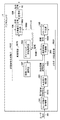
図2は、第1の実施形態のデジタルカメラ1における処理モジュールの構成を表したブロック図であり、例えば、処理の一部または全部がデジタルカメラ1に含まれる不図示のCPU及びメモリ等を用いて構成される。第1の実施形態では、処理モジュールとして、ユーザ指示取得部101、再生表示制御部102、輝度情報取得部103、ダイナミックレンジ情報保持部104、メタデータ生成部105、送信信号生成部106、画像ファイル保持部107、送信部108を含む。なお、図2では、本実施形態の説明に不要な処理モジュールに関しては省略している。
<First Embodiment>
FIG. 2 is a block diagram showing a configuration of a processing module in the
ユーザ指示取得部101は、ユーザからの指示を受け付けるための、例えば、デジタルカメラ1に配置されたボタンやタッチパネル等のユーザインタフェースとその処理部からなり、ユーザ4からの再生指示40を受け付ける。再生指示40は、複数ある画像ファイルの中で、どの画像ファイルをどのように表示するかといった指示を含んでいる。ユーザ指示取得部101は、ユーザからの再生指示40を受け付けると、再生表示制御部102へ再生制御開始指示1010を送信する。
The user
再生表示制御部102は、再生制御開始指示1010を受信すると、輝度情報取得部103へ輝度情報取得指示1020を送信し、メタデータ生成部105へメタデータ生成指示1021を送信する。また、送信信号生成部106へ送信信号生成指示1022を送信する。ここで、再生表示制御部102から各処理モジュールへ送信される情報は、表示対象の画像、表示の仕方等の情報を含む。
Upon receiving the reproduction
輝度情報取得部103は、輝度情報取得指示1020を受信すると、輝度情報としてダイナミックレンジ情報保持部104から、デジタルカメラ1が扱う輝度の範囲を示すダイナミックレンジ情報1040を取得する。デジタルカメラ1のダイナミックレンジは、一般的に撮影の設定等の要因で変化するが、第1の実施形態におけるダイナミックレンジ情報1040は、その機種のデジタルカメラ1が扱うことが可能な最大のダイナミックレンジとする。一例として、ここではダイナミックレンジ情報保持部104には、デジタルカメラ1が扱うことが可能な最大のダイナミックレンジとして、1000%という情報が保持されているものとして説明する。なお、表示対象となる複数の画像の撮影時に設定されたダイナミックレンジの最大値でもよい。
When the luminance
次に、輝度情報取得部103は、取得したダイナミックレンジ情報1040を輝度情報1030へ変換する。第1の実施形態では、ダイナミックレンジ情報1040に記載されたダイナミックレンジの値を輝度へと置き換えて輝度情報とする。例えば、1000%を1000nitsに置き換える。
Next, the luminance
メタデータ生成部105は、メタデータ生成指示1021と輝度情報1030を受信し、メタデータを生成する。ここで、第1の実施形態では、メタデータとして最大輝度の情報を含むデータを示して説明を行うが、メタデータの種類はこれに限定されるものではない。例えば、メタデータに、色域、色温度、最低輝度等の情報が付加されていてもよい。また例えば、HDMIでサポートされるMaxCLL(Maximum Content Light Level)やMaxFALL(Maximum Frame Average Light Level)の情報が付加されていてもよい。
The
メタデータ生成部105は、取得した輝度情報1030をメタデータの形式(メタデータフォーマットとして定められたフォーマット形式)へと変換し、メタデータ1050として出力する。
The
送信信号生成部106は、送信信号生成指示1022とメタデータ1050を受信し、デジタルカメラ1に接続されたディスプレイ2へ送信する為の信号を生成する。具体的には、送信信号生成部106は、送信信号生成指示1022を受信すると、送信する信号の作成に必要な画像情報1070を画像ファイル保持部107から取得する。画像ファイル保持部107は、デジタルカメラ1によって撮影された様々なダイナミックレンジを持つ画像データが画像ファイルとして保持されている。そして送信信号生成部106は、取得した画像情報1070を信号の伝送に適した形式へと変換する。
The transmission
本実施形態では、伝送に適した形式として、SMPTE ST 2084に規定されたEOTF(Electro Optical Transfer Function)に対応する形式へ変換する。ここで、SMPTE ST 2084に規定される信号は絶対輝度を表わす信号である。しかしながら、一般的に、デジタルカメラで撮影された画像ファイルの情報は、絶対輝度を表わすデータ形式では保存されてはおらず、相対的な明るさで保存されることが多い。そこで、本実施形態では、各画像ファイル内での特定の相対値(例えば18%)を特定の絶対輝度(例えば18nits)に割り当てると決め、どのようなダイナミックレンジを持つ画像ファイルであっても、その割り当てになるように形式を変換する。 In the present embodiment, as a format suitable for transmission, it is converted into a format corresponding to EOTF (Electro Optical Transfer Function) defined in SMPTE ST 2084. Here, the signal defined in SMPTE ST 2084 is a signal representing absolute brightness. However, in general, the information of an image file taken by a digital camera is not saved in a data format representing absolute brightness, and is often saved in relative brightness. Therefore, in the present embodiment, it is determined that a specific relative value (for example, 18%) in each image file is assigned to a specific absolute brightness (for example, 18 bits), and the image file having any dynamic range can be used. Convert the format to that assignment.
例えば、画像ファイルのビット幅が10bit、最大のダイナミックレンジが100%の画像ファイルAがあり、ある画素値と対応するダイナミックレンジが次のようであるものとする。 For example, it is assumed that there is an image file A in which the bit width of the image file is 10 bits and the maximum dynamic range is 100%, and the dynamic range corresponding to a certain pixel value is as follows.
*画像ファイルA(最大のダイナミックレンジ:100%)
・画素値0:ダイナミックレンジ0%
・画素値184:ダイナミックレンジ18%
・画素値1023:ダイナミックレンジ100%
この場合は、画素値0を0nits、画素値184を18nits、画素値1023(最大値)を、100nitsを表わす信号へと変換する。
* Image file A (maximum dynamic range: 100%)
・ Pixel value 0: Dynamic range 0%
-Pixel value 184: Dynamic range 18%
Pixel value 1023: 100% dynamic range
In this case, the pixel value 0 is converted into 0 nits, the pixel value 184 is converted into 18 nits, and the pixel value 1023 (maximum value) is converted into a signal representing 100 nits.
ここで、デジタルカメラ1は設定を変更することで、記録する画像ファイルのダイナミックレンジを変更可能なものがある。そのような場合は、画像ファイルの画素値と対応するダイナミックレンジの値が、画像ファイル毎に異なる場合がある。
また、画像ファイルのビット幅が10bit、最大のダイナミックレンジが1000%の画像ファイルBがあり、ある画素値と対応するダイナミックレンジの値が次のようであるものとする。
Here, some
Further, it is assumed that there is an image file B in which the bit width of the image file is 10 bits and the maximum dynamic range is 1000%, and the value of the dynamic range corresponding to a certain pixel value is as follows.
*画像ファイルB(最大のダイナミックレンジ:1000%)
・画素値0:ダイナミックレンジ0%
・画素値18:ダイナミックレンジ18%
・画素値1023:ダイナミックレンジ1000%
この場合は、画素値0を0nits、画素値18を18nits、画素値1023(最大値)を1000nitsを表わす信号へと変換する。
* Image file B (maximum dynamic range: 1000%)
・ Pixel value 0: Dynamic range 0%
-Pixel value 18: Dynamic range 18%
Pixel value 1023: Dynamic range 1000%
In this case, the pixel value 0 is converted into a signal representing 0 nits, the pixel value 18 is converted into a signal representing 18 nits, and the pixel value 1023 (maximum value) is converted into a signal representing 1000 nits.
このように、ダイナミックレンジが異なる画像ファイルが生成可能なデジタルカメラでは、一般的に、画像ファイルの形式毎に、画像ファイルの画素値と対応するダイナミックレンジに関する情報を内部に保持しているため、上述したような変換を行うことができる。 In this way, a digital camera capable of generating image files having different dynamic ranges generally holds information on the pixel value of the image file and the corresponding dynamic range internally for each image file format. The conversion as described above can be performed.
このような変換(以下、「輝度変換」と呼ぶ。)を行うことで、例えばダイナミックレンジが100%の画像ファイルでも、ダイナミックレンジが1000%の画像ファイルでも、ある相対値は同じ輝度を表わす信号へと変換されることとなる。 By performing such conversion (hereinafter referred to as "luminance conversion"), for example, an image file having a dynamic range of 100% or an image file having a dynamic range of 1000% has a relative value indicating a signal having the same brightness. Will be converted to.
送信信号生成部106は、受信したメタデータ1050と、伝送に適した形式へと変換された画像情報とを関連付けて、送信信号1060として送信部108へ送信する。送信部108は、HDMIなどの規格の端子とその制御部より構成され、送信信号生成部106から送られる送信信号1060をデジタルカメラ1の外部へ送信する。
The transmission
上記の通り第1の実施形態によれば、それぞれの画像において相対的に表現された画素値を、共通のダイナミックレンジにおける輝度値に変換した画像情報に、共通の最大輝度の情報を含むメタデータを付与する。ディスプレイ2では、メタデータに含まれる共通の最大輝度が、ディスプレイ2で表示可能な輝度となるように画像情報の輝度値を変換して表示することで、同じ輝度で表示を行いたい画像データの領域を、同一の輝度信号として扱うことが可能となる。
As described above, according to the first embodiment, metadata including common maximum brightness information in image information obtained by converting pixel values relatively expressed in each image into brightness values in a common dynamic range. Is given. In the
<第2の実施形態>
次に、本発明の第2の実施形態について説明する。第2の実施形態では、デジタルカメラ1に、他の外部デジタルカメラが接続可能であって、接続した外部デジタルカメラから画像ファイルを受信、保持することができる場合の処理について説明する。なお、他のデジタルカメラ1から画像ファイルを取得する形態として可搬の記録媒体を介して取得する形態でもよい。以下、一例として、画像ファイルを生成したデジタルカメラの情報に基づいてメタデータを決定する例について説明する。
<Second embodiment>
Next, a second embodiment of the present invention will be described. In the second embodiment, a process in which another external digital camera can be connected to the
図3は、第2の実施形態のデジタルカメラ1における処理モジュールの構成を表したブロック図であり、例えば、処理の一部または全部がデジタルカメラ1に含まれる不図示のCPU及びメモリ等を用いて構成される。第2の実施形態におけるデジタルカメラ1の処理は、図2を参照して説明した処理と比較して、輝度情報取得部201における処理が異なる。それ以外は、第1の実施形態と同様であるため、同じ参照番号を付して適宜説明を省略する。
FIG. 3 is a block diagram showing a configuration of a processing module in the
輝度情報取得部201は、輝度情報取得指示1020を受信すると、画像ファイル保持部107から表示対象の画像の画像情報1070を取得する。
Upon receiving the luminance
図4は、ある画像情報に含まれる情報の一例を示した図である。画像情報は、画像のデータである画像データ部と、撮影時情報からなる撮影時情報部とから構成される。ここで、撮影時情報とは、例えば、カメラの設定から決定されたダイナミックレンジ、撮影日時、撮影に使用したカメラの識別情報、撮影モード(例えば、夜景の撮影に適した夜景モード等のカメラの動作モード)等の情報である。 FIG. 4 is a diagram showing an example of information included in a certain image information. The image information is composed of an image data unit which is image data and a shooting information unit which is composed of shooting information. Here, the shooting information includes, for example, the dynamic range determined from the camera settings, the shooting date and time, the identification information of the camera used for shooting, and the shooting mode (for example, the night view mode suitable for shooting a night view). Information such as operation mode).
輝度情報取得部201は、画像情報1070から、撮影に使用したカメラの識別情報を取得し、その識別情報に応じたダイナミックレンジ情報1040をダイナミックレンジ情報保持部104から取得する。第2の実施形態では、ダイナミックレンジ情報保持部104は、カメラの識別情報毎のダイナミックレンジ情報を保持しているものとする。なお、カメラの識別情報に該当するダイナミックレンジ情報が無い場合、ダイナミックレンジ情報保持部104は、他のカメラのダイナミックレンジ情報を代わりに提供する。
The luminance
そして、輝度情報取得部201は、取得したダイナミックレンジ情報1040を、第1の実施形態と同様の方法で輝度情報1030へ変換し、メタデータ生成部105に出力する。メタデータ生成部105では、取得した輝度情報1030をメタデータの形式へと変換し、メタデータ1050として出力する。
Then, the luminance
送信信号生成部106では、第1の実施形態と同様に、受信したメタデータ1050と、伝送に適した形式へと変換された画像情報とを関連付けて、送信信号1060として送信部108へ送信する。
Similar to the first embodiment, the transmission
上記の通り第2の実施形態によれば、撮影したデジタルカメラが同一の画像に対して、共通のダイナミックレンジにおける輝度値に変換した画像情報に、共通の最大輝度の情報を含むメタデータを付与する。これにより、ディスプレイ2において、同一のデジタルカメラで撮影を行った画像に対して、同じ輝度で表示を行いたい画像データの領域を同一の輝度信号として扱うことが可能となる。
As described above, according to the second embodiment, for the same image taken by the digital camera, metadata including the common maximum brightness information is added to the image information converted into the brightness values in the common dynamic range. do. As a result, in the
<第3の実施形態>
次に、本発明の第3の実施形態について説明する。第1の実施形態では、デジタルカメラ1内の全ての画像に共通の最大輝度の情報を含むメタデータを付加する例について説明を行った。これに対し、第3の実施形態では、画像をグループ化し、グループ毎にグループに含まれる画像に対して同じメタデータを付加する例につい説明をする。
<Third embodiment>
Next, a third embodiment of the present invention will be described. In the first embodiment, an example in which metadata including common maximum luminance information is added to all the images in the
図5は、第3の実施形態のデジタルカメラ1における処理モジュールの構成を表したブロック図であり、例えば、処理の一部または全部がデジタルカメラ1に含まれる不図示のCPU及びメモリ等を用いて構成される。第3の実施形態におけるデジタルカメラ1の処理モジュールは、図2を参照して説明した処理モジュールと比較して、グループ化処理部302を含み、これに伴い、再生表示制御部301、輝度情報取得部303、送信信号生成部304における処理が異なる。それ以外は、第1の実施形態と同様であるため、同じ参照番号を付して適宜説明を省略する。
FIG. 5 is a block diagram showing a configuration of a processing module in the
再生表示制御部301は、再生制御開始指示1010を受信すると、グループ化処理部302へグループ化指示3010を送信し、輝度情報取得部303へ輝度情報取得指示3011を送信し、メタデータ生成部105へメタデータ生成指示1021を送信する。また、送信信号生成部304へ送信信号生成指示1022を送信する。ここで、再生表示制御部301から各処理モジュールへ送信される情報は、表示対象の画像、表示の仕方等の情報を含む。
Upon receiving the reproduction
グループ化処理部302は、グループ化指示3010を受け、画像ファイルのグループ化を行う。ここで言うグループ化とは、予め決められたグループ化条件に従って、同じメタデータを付加すべき画像ファイルをグループに分類することである。
The
グループ化条件は、例えば、画像の撮影日時、撮影モード、撮影後の画像処理の設定、シャッタースピード等の情報が、1つ以上同一もしくは近いことである。グループ化条件はデジタルカメラ1に予め設定されていても良いし、ユーザが選択可能なようにしてもよい。また、グループ化する際は、表示を行う順序を考慮に入れてグループ化を行ってもよい。
The grouping condition is, for example, that one or more pieces of information such as the shooting date and time of the image, the shooting mode, the setting of image processing after shooting, and the shutter speed are the same or close to each other. The grouping conditions may be preset in the
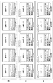
ここで図6を用いて、グループ化処理の一例について説明する。図6(a)は、画像ファイル保持部107が保持する画像ファイルの例を示す。なお、画像ファイルpicture001の画像から昇順に表示を行うものとし、グループ化条件として、撮影日時と撮影モードの両方が同じであることとする。
Here, an example of the grouping process will be described with reference to FIG. FIG. 6A shows an example of an image file held by the image
図6(b)は、グループ化条件のみに基づいてグループ化した例である。図6(b)では、画像ファイルpicture001、picture002、picture004、picture005が、グループ1、画像ファイルpicture003のみがグループ2となっている。
FIG. 6B is an example of grouping based only on the grouping conditions. In FIG. 6B, the image files picture001, picture002, picture004, and picture005 are
図6(c)は、表示を行う順序(表示順)を考慮に入れてグループ化した例である。最初に表示を行う画像ファイルpicture001から昇順にグループ化条件が同じとなる画像ファイルをグループとしていく。画像ファイルpicture001からpicture002まではグループ化条件を満たしているので、同一グループ(グループ1)である。画像ファイルpicture003からはまた別のグループとしてグループ化を行うが、その次の画像ファイルpicture004は画像ファイルpicture003とのグループ化条件を満たしていない。そのため、画像ファイルpicture003は単一の画像ファイルによるグループ(グループ2)となる。同様に、残りの画像ファイルpicture004とpicture005はグループ化条件を満たしているため、同一のグループ(グループ3)とする。 FIG. 6C is an example of grouping in consideration of the display order (display order). From the image file picture001 to be displayed first, the image files having the same grouping conditions in ascending order are grouped. Since the image files picture001 to picture002 satisfy the grouping conditions, they are in the same group (group 1). The image file picture003 is grouped as another group, but the next image file picture004 does not satisfy the grouping condition with the image file picture003. Therefore, the image file picture003 is a group (group 2) consisting of a single image file. Similarly, since the remaining image files picture004 and picture005 satisfy the grouping conditions, they are set to the same group (group 3).
ここで、表示を行う順序を考慮に入れてグループ化するのは、あるグループに含まれる画像を連続して表示しないのであれば、画像処理が変化することによる弊害を人間が感じにくい為、異なるメタデータを付与することによる弊害が少ないためである。また、グループに含まれる画像ファイルの数が少ない方が、より画像に適した最大輝度を設定することが可能になるため、画像に適したダイナミックレンジで表示できる可能性が高くなるからである。 Here, grouping in consideration of the display order is different because it is difficult for humans to perceive the harmful effects of changes in image processing unless the images included in a certain group are displayed continuously. This is because there are few harmful effects due to the addition of metadata. Further, the smaller the number of image files included in the group, the higher the possibility that the maximum brightness suitable for the image can be set, and therefore the dynamic range suitable for the image can be displayed.
グループ化処理部302は、上述したような方法で画像ファイルをグループ化した情報を、グループ化情報3020として輝度情報取得部303及び送信信号生成部304へ出力する。図7はグループ化情報3020の一例を示す図である。
The
輝度情報取得部303は、輝度情報取得指示3011とグループ化情報3020を取得すると、グループ化情報3020に記述されたグループ毎に、輝度情報を取得する。ここでは、各グループに属する画像ファイルが持つダイナミックレンジの中で、最も大きいダイナミックレンジを取得し、それを輝度へと置き換え、そのグループの最大輝度情報とする。例えば、グループ内の最大のダイナミックレンジが1000%であれば、そのグループの最大輝度情報は1000nitsとなる。
When the luminance
図6(c)に示す例では、グループ1の最大輝度情報は200nits、グループ2の最大輝度情報は300nits、グループ3の輝度情報は400nitsとなる。
In the example shown in FIG. 6C, the maximum luminance information of the
なお、第3の実施形態では、グループの最大輝度情報を各グループに属する画像ファイルが持つダイナミックレンジの中で最も大きいダイナミックレンジから取得する例を示したが、輝度情報の取得方法はそれに限定されない。画像の撮影時情報に含まれる情報(例えば撮影モード)毎に対応する輝度情報を記したテーブルを保持しておき、それを用いて各グループの画像ファイルの撮影時情報から最大輝度情報を取得してもよい。 In the third embodiment, an example of acquiring the maximum luminance information of a group from the largest dynamic range among the dynamic ranges of the image files belonging to each group is shown, but the method of acquiring the luminance information is not limited thereto. .. A table in which the corresponding brightness information is described for each information included in the image shooting information (for example, shooting mode) is held, and the maximum brightness information is acquired from the shooting information of the image file of each group by using the table. You may.
送信信号生成部304は、送信信号生成指示1022とメタデータ1050を受信し、デジタルカメラ1に接続されたディスプレイ2へ送信する為の信号を生成する。具体的には、送信信号生成部304は、送信信号生成指示1022を受信すると、送信する信号の作成に必要な画像情報1070を画像ファイル保持部107から取得し、グループ化情報3020をグループ化処理部302から取得する。そして送信信号生成部106は取得した画像情報1070を、第1の実施形態で説明した方法により輝度変換し、更に、信号の伝送に適した形式へと変換する。第3の実施形態では、伝送に適した形式としてSMPTE ST 2084に規定されたEOTFに対応する形式へ変換する。送信信号生成部304は、受信したメタデータ1050と、伝送に適した形式へと変換した画像情報を関連付けて、送信信号3040として送信部108へ送信する。
The transmission
このように、画像をグループ分けし、グループ毎に、共通のダイナミックレンジにおける輝度値に変換した画像情報に、共通の最大輝度の情報を含むメタデータを付与する。これにより、ディスプレイ2において、グループ毎に、同じ輝度で表示を行いたい画像データの領域を、同一の輝度信号として扱うことが可能となる。
In this way, the images are divided into groups, and the image information converted into the luminance values in the common dynamic range is given metadata including the common maximum luminance information for each group. As a result, in the
<第4の実施形態>
次に、本発明の第4の実施形態について説明する。上述した第1〜第3の実施形態では、各画像に1つのメタデータを生成する場合について説明した。これに対し、第4の実施形態では、各画像に、全ての画像に共通する共通メタデータと、画像毎の個別メタデータをそれぞれ生成し、スライドショウの再生間隔によって、それら2つのメタデータから最終的なメタデータを生成する例について説明する。
<Fourth Embodiment>
Next, a fourth embodiment of the present invention will be described. In the first to third embodiments described above, a case where one metadata is generated for each image has been described. On the other hand, in the fourth embodiment, common metadata common to all images and individual metadata for each image are generated for each image, and the two metadata are used according to the playback interval of the slide show. An example of generating the final metadata will be described.
なお、第4の実施形態におけるデジタルカメラ1の各処理モジュールの構成は、図3に示すものと同様であるが、処理の詳細内容が異なるため、図3を参照して以下に説明する。
The configuration of each processing module of the
ユーザ指示取得部101は、例えばデジタルカメラ1に配置されたボタンやタッチパネル等のユーザインタフェースとその処理部からなり、ユーザからのユーザ指示41を受け付ける。第4の実施形態ではユーザ指示41は、スライドショウ表示指示を含む。なお、スライドショウ表示指示とは、デジタルカメラ1内に保持された画像ファイルを、ユーザが指定した時間間隔で切り替えて順次表示するスライドショウ表示を、デジタルカメラ1に接続されたディスプレイ2で行う、という指示である。このスライドショウ表示指示は、表示を開始する画像の指定や、表示を切り替える時間間隔(以下、切り替え時間)の指定を含む。
The user
ユーザ指示取得部101は、ユーザからスライドショウ表示指示を受け付けると、再生表示制御部102へ再生制御開始指示1010を送信する。
When the user
再生表示制御部102は、再生制御開始指示1010を受信すると、輝度情報取得部201へ輝度情報取得指示1020を送信し、メタデータ生成部105へメタデータ生成指示1021を送信する。また、送信信号生成部106へ送信信号生成指示1022を送信する。ここで、各処理モジュールへ送信される情報は、スライドショウ表示指示により指定された、表示を開始する画像や、表示の切り替え時間等の情報を含む。
Upon receiving the reproduction
輝度情報取得部201は、輝度情報取得指示1020を受け、最大輝度情報を取得する。第4の実施形態における最大輝度情報は、画像ファイル保持部107に保持された画像全体に共通の共通輝度情報と、画像毎の個別輝度情報とから構成される。なお、第4の実施形態では、画像ファイル保持部107に保持された画像全体に共通の共通輝度情報を取得するが、本発明はこれに限られるものではない。例えば、第2の実施形態で説明したように他のデジタルカメラにより撮影された画像ファイルを有する場合には、デジタルカメラ毎に共通の共通輝度情報を取得してもよい。また、スライドショウ表示指示に表示する複数の画像が指定されている場合には、指定された複数の画像に共通の共通輝度情報を取得してもよい。
The luminance
第4の実施形態における輝度情報は、ダイナミックレンジの情報から生成される。そこで、輝度情報取得部201は、輝度情報取得指示1020を受信すると、まず共通のダイナミックレンジ情報として、ダイナミックレンジ情報保持部104からダイナミックレンジ情報1040を取得する。なお、共通のダイナミックレンジは、第1の実施形態と同様に、デジタルカメラ1が扱うことが可能な輝度の範囲とする。一例として、ここでは、ダイナミックレンジ情報保持部104には、デジタルカメラ1が扱うことが可能な最大のダイナミックレンジとして、1000%という情報が保持されているものとする。
The luminance information in the fourth embodiment is generated from the dynamic range information. Therefore, when the luminance
次に、輝度情報取得部201は、画像毎のダイナミックレンジ情報を取得する為、画像ファイル保持部107から画像情報1070を取得する。画像情報には、図4を参照して上述したように、画像のデータである画像データ部と、撮影時情報からなる撮影時情報部から構成される。輝度情報取得部201は、取得した画像情報1070内の撮影時情報部に含まれるダイナミックレンジ情報を、画像毎のダイナミックレンジ情報とする。
Next, the luminance
輝度情報取得部201は、取得した共通のダイナミックレンジ情報と画像毎のダイナミックレンジ情報を、それぞれ共通輝度情報と個別輝度情報へ変換する。第4の実施形態では、第1の実施形態と同様に、それぞれのダイナミックレンジ情報に記載されたダイナミックレンジの値を輝度へと置き換えて輝度情報とする。例えば1000%を1000nitsへ置き換える。そして、作成した共通輝度情報と個別輝度情報とを合わせて、輝度情報1030とする。
The luminance
メタデータ生成部105は、メタデータ生成指示1021と輝度情報1030を受信し、メタデータを生成する。ここで、第4の実施形態では、メタデータとして最大輝度の情報を含むデータを示して説明を行うが、メタデータの種類はこれに限定されるものではない。例えば、メタデータに、色域、色温度、最低輝度等の情報が付加されていてもよい。また例えば、HDMIでサポートされるMaxCLLやMaxFALLの情報が付加されていてもよい。
The
メタデータ生成部105は、取得した輝度情報1030をメタデータの形式(メタデータフォーマットとして定められたフォーマット形式)へと変換し、それをメタデータ1050として出力する。第4の実施形態においては、メタデータ1050は、共通メタデータと、個別メタデータを含む。
The
送信信号生成部106は、送信信号生成指示1022とメタデータ1050を受信し、デジタルカメラ1に接続されたディスプレイ2へ送信する為の信号を生成する。具体的には、送信信号生成部106は、送信信号生成指示1022を受信すると、送信する信号の作成に必要な画像情報1070を画像ファイル保持部107から取得する。そして送信信号生成部106は取得した画像情報1070を、第1の実施形態で説明した方法により輝度変換し、更に、信号の伝送に適した形式へと変換する。第4の実施形態では、伝送に適した形式としてSMPTE ST 2084に規定されたEOTFに対応する形式へ変換する。
The transmission
次に、本第4の実施形態における最大輝度の決定方法について説明する。送信信号生成部106は、送信信号生成指示1022に含まれるスライドショウの表示の切り替え時間を基に、共通メタデータと個別メタデータを合成して送信用のメタデータを生成する。ここで、合成比率は、切り替え時間が短いほど共通メタデータの比率が高くし、反対に切り替え時間が長いほど個別メタデータの比率を高くする。これは時間間隔が短い程、メタデータの変化によるテレビ側の画像処理の変更が頻繁に発生する為に、画像間でメタデータの差を小さくするためである。また、個別メタデータを用いた方が、画像単体で見ればテレビ側の画像処理はより望ましくなる傾向が強い為、時間間隔が長い場合(画像処理の変更があまり発生しない場合)は画像毎のメタデータを重視する。
Next, a method for determining the maximum brightness in the fourth embodiment will be described. The transmission
そこで、送信信号生成部106は、内部に切り替え時間に応じて、共通メタデータと個別メタデータの合成比率を決定するテーブルを予め保持しておく。そして、このテーブルの情報に応じて、共通メタデータと個別メタデータを合成し、送信用のメタデータを生成する。そして、送信信号生成部106は、合成したメタデータと、伝送に適した形式へと変換した画像情報とを関連付けて、送信信号1060として送信部108へ送信する。
Therefore, the transmission
このように、スライドショウの切り替え時間に応じて最大輝度を調整することで、より見やすい表示が行えるようにすることが可能となる。 In this way, by adjusting the maximum brightness according to the switching time of the slide show, it is possible to make the display easier to see.
<他の実施形態>
上述した第1から第4の実施形態では、デジタルカメラ1において、ディスプレイ2に出力する画像ファイルを生成する例について説明したが、本発明はこれに限られるものではない。例えば、図2、図3または図5に示す処理モジュールを、外部の画像処理装置において構成し、画像ファイルを撮像装置から取得するようにしてもよい。その場合、撮像装置と画像処理装置とにより、撮像システムを構成することができる。
<Other embodiments>
In the first to fourth embodiments described above, an example of generating an image file to be output to the
また、本発明は、上述した第1から第4の実施形態を適宜組み合わせて実施してもよい。 Further, the present invention may be carried out by appropriately combining the above-mentioned first to fourth embodiments.
また、本発明は、上述の実施形態の1以上の機能を実現するプログラムを、ネットワーク又は記憶媒体を介してシステム又は装置に供給し、そのシステム又は装置のコンピュータにおける1つ以上のプロセッサーがプログラムを読出し実行する処理でも実現可能である。また、1以上の機能を実現する回路(例えば、ASIC)によっても実現可能である。 The present invention also supplies a program that realizes one or more functions of the above-described embodiment to a system or device via a network or storage medium, and one or more processors in the computer of the system or device implement the program. It can also be realized by the process of reading and executing. It can also be realized by a circuit (for example, ASIC) that realizes one or more functions.
1:デジタルカメラ、2:ディスプレイ、3:ケーブル、101:ユーザ指示取得部、102:再生表示制御部、103,201,303:輝度情報取得部、104:ダイナミックレンジ情報保持部、105:メタデータ生成部、106,304:送信信号生成部、107:画像ファイル保持部、108:送信部、302:グループ化処理部 1: Digital camera, 2: Display, 3: Cable, 101: User instruction acquisition unit, 102: Playback display control unit, 103, 201, 303: Brightness information acquisition unit, 104: Dynamic range information retention unit, 105: Metadata Generation unit, 106, 304: Transmission signal generation unit, 107: Image file holding unit, 108: Transmission unit, 302: Grouping processing unit
Claims (17)
前記撮像装置により得られた画像データと、前記画像データの最大輝度を示すための情報である最大輝度情報とを、外部装置に出力する出力手段と、
前記撮像装置が取り扱い可能な最大輝度を取得する取得手段と、
前記最大輝度情報として、前記取得手段により取得された最大輝度を出力するよう前記出力手段を制御する制御手段と、
前記画像データを得るために用いられた輝度の範囲に基づく画像データの画素値を、前記撮像装置が取り扱い可能な輝度の範囲に基づく輝度値に変換する変換手段と、
を有することを特徴とする画像処理装置。 An image processing device that processes image data obtained by an image pickup device.
An output means for outputting the image data obtained by the image pickup apparatus and the maximum luminance information, which is information for indicating the maximum luminance of the image data, to an external device.
Obtaining means for obtaining a maximum Brightness possible treats taken by the imaging device,
As the maximum luminance information, a control means for controlling the output means so as to output the maximum luminance acquired by the acquisition means, and
Conversion means for converting pre-pixel value of the image data based on the range of luminance that was used to obtain the Kiga image data, the luminance value in which the imaging device is based on a range of possible handling brightness,
An image processing device characterized by having.
前記取得手段は、前記設定可能な複数の輝度の範囲に含まれる輝度のうち、最大輝度を取得することを特徴とする請求項1に記載の画像処理装置。 The image pickup device can set a plurality of brightness ranges, and the image pickup device can set a plurality of brightness ranges.
The acquisition unit, of the luminance contained in the scope of the settable plurality of luminance, an image processing apparatus according to claim 1, characterized in that to obtain the maximum brightness.
前記取得手段は、前記複数の画像データのそれぞれを取得した撮像装置の情報に基づき、前記複数の撮像装置のそれぞれが取り扱い可能な最大輝度を取得することを特徴とする請求項1乃至3のいずれか1項に記載の画像処理装置。 Any of claims 1 to 3, wherein the acquisition means acquires the maximum brightness that can be handled by each of the plurality of image pickup devices based on the information of the image pickup apparatus that has acquired each of the plurality of image data. The image processing apparatus according to item 1.
出力される画像データと、前記画像データの最大輝度を示すための情報である最大輝度情報とを、外部装置に出力する出力手段と、
撮像により得られた複数の画像データを分類する分類手段と、
前記出力手段により、所定のグループに分類された画像データの1つを出力する場合、前記最大輝度情報として、前記出力される画像データの最大輝度ではなく、前記所定のグループに分類された複数の画像データにおける最大輝度を出力するよう前記出力手段を制御する制御手段と、
を有することを特徴とする画像処理装置。 An image processing device capable of processing a plurality of image data having a plurality of luminance ranges.
An output means for outputting the output image data and the maximum luminance information, which is information for indicating the maximum luminance of the image data, to an external device.
A classification means for classifying a plurality of image data obtained by imaging, and
When one of the image data classified into a predetermined group is output by the output means, the maximum brightness information is not the maximum brightness of the output image data but a plurality of image data classified into the predetermined group. A control means that controls the output means so as to output the maximum brightness in the image data, and
An image processing device characterized by having.
出力手段が、前記撮像装置により得られた画像データと、前記画像データの最大輝度を示すための情報である最大輝度情報とを、外部装置に出力する出力工程と、
取得手段が、前記撮像装置が取り扱い可能な最大輝度を取得する取得工程と、
制御手段が、前記最大輝度情報として、前記取得手段により取得された最大輝度を出力するよう前記出力手段を制御する制御工程と、
変換手段が、前記画像データを得るために用いられた輝度の範囲に基づく画像データの画素値を、前記撮像装置が取り扱い可能な輝度の範囲に基づく輝度値に変換する変換工程と、
を有することを特徴とする画像処理方法。 An image processing method for processing image data obtained by an image pickup device.
An output step in which the output means outputs the image data obtained by the image pickup apparatus and the maximum luminance information which is information for indicating the maximum luminance of the image data to an external device.
An acquisition step acquiring means for acquiring the maximum Brightness that can treats the image pickup device takes,
A control step in which the control means controls the output means so as to output the maximum brightness acquired by the acquisition means as the maximum brightness information.
Conversion means, a conversion step of converting before the pixel values of the image data based on the range of luminance that was used to obtain the Kiga image data, the luminance value in which the imaging device is based on a range of possible handling brightness,
An image processing method characterized by having.
出力手段が、出力される画像データと、前記画像データの最大輝度を示すための情報である最大輝度情報とを、外部装置に出力する出力工程と、
分類手段が、撮像により得られた複数の画像データを分類する分類工程と、
制御手段が、前記出力工程で、所定のグループに分類された画像データの1つを出力する場合、前記最大輝度情報として、前記出力される画像データの最大輝度ではなく、前記所定のグループに分類された複数の画像データにおける最大輝度を出力するよう前記出力手段を制御する制御工程と、
を有することを特徴とする画像処理方法。 An image processing method capable of processing a plurality of image data having a plurality of luminance ranges.
An output process in which the output means outputs the output image data and the maximum luminance information, which is information for indicating the maximum luminance of the image data, to an external device.
The classification means is a classification process for classifying a plurality of image data obtained by imaging, and
When the control means outputs one of the image data classified into a predetermined group in the output step, the maximum brightness information is classified into the predetermined group instead of the maximum brightness of the output image data. A control step that controls the output means so as to output the maximum brightness of the plurality of image data.
An image processing method characterized by having.
Priority Applications (4)
| Application Number | Priority Date | Filing Date | Title |
|---|---|---|---|
| JP2017126515A JP6948173B2 (en) | 2017-06-28 | 2017-06-28 | Image processing equipment and methods, imaging equipment, and imaging systems |
| PCT/JP2018/021859 WO2019003850A1 (en) | 2017-06-28 | 2018-06-07 | Image processing device and method |
| CN201880043095.1A CN110800285B (en) | 2017-06-28 | 2018-06-07 | Image processing apparatus, image processing method, and storage medium |
| US16/708,164 US11252335B2 (en) | 2017-06-28 | 2019-12-09 | Image processing apparatus and method, and non-transitory computer-readable storage medium |
Applications Claiming Priority (1)
| Application Number | Priority Date | Filing Date | Title |
|---|---|---|---|
| JP2017126515A JP6948173B2 (en) | 2017-06-28 | 2017-06-28 | Image processing equipment and methods, imaging equipment, and imaging systems |
Publications (3)
| Publication Number | Publication Date |
|---|---|
| JP2019009731A JP2019009731A (en) | 2019-01-17 |
| JP2019009731A5 JP2019009731A5 (en) | 2020-08-06 |
| JP6948173B2 true JP6948173B2 (en) | 2021-10-13 |
Family
ID=64740614
Family Applications (1)
| Application Number | Title | Priority Date | Filing Date |
|---|---|---|---|
| JP2017126515A Active JP6948173B2 (en) | 2017-06-28 | 2017-06-28 | Image processing equipment and methods, imaging equipment, and imaging systems |
Country Status (4)
| Country | Link |
|---|---|
| US (1) | US11252335B2 (en) |
| JP (1) | JP6948173B2 (en) |
| CN (1) | CN110800285B (en) |
| WO (1) | WO2019003850A1 (en) |
Families Citing this family (1)
| Publication number | Priority date | Publication date | Assignee | Title |
|---|---|---|---|---|
| JP7256663B2 (en) * | 2019-03-26 | 2023-04-12 | キヤノン株式会社 | Image output device and its control method |
Family Cites Families (11)
| Publication number | Priority date | Publication date | Assignee | Title |
|---|---|---|---|---|
| JP2014052494A (en) * | 2012-09-06 | 2014-03-20 | Sharp Corp | Image display device, control method of image display device, control program of image display device, and recording medium recording control program |
| JP2015169722A (en) * | 2014-03-05 | 2015-09-28 | ソニー株式会社 | Imaging apparatus |
| CN106105177B (en) * | 2014-06-10 | 2019-09-27 | 松下知识产权经营株式会社 | Transform method and converting means |
| JP6421504B2 (en) | 2014-07-28 | 2018-11-14 | ソニー株式会社 | Image processing apparatus and image processing method |
| JP2016058848A (en) * | 2014-09-08 | 2016-04-21 | ソニー株式会社 | Image processing system and image processing method |
| WO2016072347A1 (en) * | 2014-11-07 | 2016-05-12 | ソニー株式会社 | Transmission device, transmission method, reception device, and reception method |
| KR102322709B1 (en) * | 2015-04-29 | 2021-11-08 | 엘지디스플레이 주식회사 | Image processing method, image processing circuit and display device using the same |
| EP3739564A1 (en) * | 2015-08-31 | 2020-11-18 | LG Electronics Inc. | Image display apparatus |
| JP6581862B2 (en) * | 2015-09-18 | 2019-09-25 | 日本放送協会 | Video camera for HDR-SDR integrated production |
| JP6729055B2 (en) * | 2016-06-23 | 2020-07-22 | セイコーエプソン株式会社 | Video processing device, display device, and video processing method |
| CN106101679B (en) * | 2016-08-23 | 2018-01-12 | 青岛海信电器股份有限公司 | The processing method and processing system of high dynamic range signal |
-
2017
- 2017-06-28 JP JP2017126515A patent/JP6948173B2/en active Active
-
2018
- 2018-06-07 WO PCT/JP2018/021859 patent/WO2019003850A1/en active Application Filing
- 2018-06-07 CN CN201880043095.1A patent/CN110800285B/en active Active
-
2019
- 2019-12-09 US US16/708,164 patent/US11252335B2/en active Active
Also Published As
| Publication number | Publication date |
|---|---|
| US11252335B2 (en) | 2022-02-15 |
| JP2019009731A (en) | 2019-01-17 |
| CN110800285A (en) | 2020-02-14 |
| CN110800285B (en) | 2021-07-27 |
| US20200120254A1 (en) | 2020-04-16 |
| WO2019003850A1 (en) | 2019-01-03 |
Similar Documents
| Publication | Publication Date | Title |
|---|---|---|
| US9910865B2 (en) | Method for capturing the moment of the photo capture | |
| US10567727B2 (en) | Reproduction method, creation method, reproduction device, creation device, and recording medium | |
| US10600170B2 (en) | Method and device for producing a digital image | |
| US20160381302A1 (en) | Image-processing apparatus and image-processing method | |
| US9432574B2 (en) | Method of developing an image from raw data and electronic apparatus | |
| US20140375781A1 (en) | Image processing apparatus for endoscope, endoscope system and image processing method for endoscope | |
| US20150036020A1 (en) | Method for sharing original photos along with final processed image | |
| JP6711275B2 (en) | Image display control device, transmission device, image display control method, and program | |
| JP6948173B2 (en) | Image processing equipment and methods, imaging equipment, and imaging systems | |
| JP2019080156A (en) | Image processing method and image processing apparatus | |
| US20190266710A1 (en) | Image processing apparatus, image processing method, and storage medium | |
| US9967408B2 (en) | Information setting apparatus, information management apparatus, information generation apparatus, and method and program for controlling the same | |
| US20240171696A1 (en) | Image processing apparatus, control method and storage medium | |
| JP2013219619A (en) | Image pick-up device | |
| US11775157B2 (en) | Image processing apparatus, image processing system, and control method for processing a second image with adjusting level of a first image | |
| JP2019009731A5 (en) | ||
| US11871124B2 (en) | Image capturing apparatus, method of controlling the same, and non-transitory computer-readable storage medium | |
| JP6161385B2 (en) | Imaging apparatus and control method thereof | |
| KR20120110440A (en) | Non-realtime image processing method, image picturing apparatus and image processing system thereof | |
| JP2020064102A (en) | Display unit and display method | |
| JP2021078051A (en) | Image processing device and image control method, program, and storage medium | |
| JP2018152702A (en) | Image processing device and image processing method | |
| JP2020021973A (en) | Imaging apparatus, control method of the same, and program | |
| JP2018088618A (en) | Imaging device | |
| JP2016034088A (en) | Image storage device, image management method, and program |
Legal Events
| Date | Code | Title | Description |
|---|---|---|---|
| A521 | Request for written amendment filed |
Free format text: JAPANESE INTERMEDIATE CODE: A523 Effective date: 20200624 |
|
| A621 | Written request for application examination |
Free format text: JAPANESE INTERMEDIATE CODE: A621 Effective date: 20200624 |
|
| RD01 | Notification of change of attorney |
Free format text: JAPANESE INTERMEDIATE CODE: A7421 Effective date: 20210103 |
|
| A521 | Request for written amendment filed |
Free format text: JAPANESE INTERMEDIATE CODE: A523 Effective date: 20210113 |
|
| TRDD | Decision of grant or rejection written | ||
| A01 | Written decision to grant a patent or to grant a registration (utility model) |
Free format text: JAPANESE INTERMEDIATE CODE: A01 Effective date: 20210820 |
|
| A61 | First payment of annual fees (during grant procedure) |
Free format text: JAPANESE INTERMEDIATE CODE: A61 Effective date: 20210917 |
|
| R151 | Written notification of patent or utility model registration |
Ref document number: 6948173 Country of ref document: JP Free format text: JAPANESE INTERMEDIATE CODE: R151 |