JP6937327B2 - Anatomical blockage - Google Patents
Anatomical blockage Download PDFInfo
- Publication number
- JP6937327B2 JP6937327B2 JP2018568178A JP2018568178A JP6937327B2 JP 6937327 B2 JP6937327 B2 JP 6937327B2 JP 2018568178 A JP2018568178 A JP 2018568178A JP 2018568178 A JP2018568178 A JP 2018568178A JP 6937327 B2 JP6937327 B2 JP 6937327B2
- Authority
- JP
- Japan
- Prior art keywords
- shaped structure
- bell
- double
- walled
- plate
- Prior art date
- Legal status (The legal status is an assumption and is not a legal conclusion. Google has not performed a legal analysis and makes no representation as to the accuracy of the status listed.)
- Active
Links
- 229910001285 shape-memory alloy Inorganic materials 0.000 claims description 12
- 229910001000 nickel titanium Inorganic materials 0.000 claims description 7
- HLXZNVUGXRDIFK-UHFFFAOYSA-N nickel titanium Chemical group [Ti].[Ti].[Ti].[Ti].[Ti].[Ti].[Ti].[Ti].[Ti].[Ti].[Ti].[Ni].[Ni].[Ni].[Ni].[Ni].[Ni].[Ni].[Ni].[Ni].[Ni].[Ni].[Ni].[Ni].[Ni] HLXZNVUGXRDIFK-UHFFFAOYSA-N 0.000 claims description 6
- 241000288673 Chiroptera Species 0.000 claims description 3
- 239000010410 layer Substances 0.000 description 25
- 210000003484 anatomy Anatomy 0.000 description 24
- 239000000463 material Substances 0.000 description 17
- 238000009434 installation Methods 0.000 description 16
- 210000005248 left atrial appendage Anatomy 0.000 description 15
- 238000000034 method Methods 0.000 description 13
- 238000011084 recovery Methods 0.000 description 7
- 229910052751 metal Inorganic materials 0.000 description 6
- 239000002759 woven fabric Substances 0.000 description 6
- -1 copper-aluminum-nickel Chemical compound 0.000 description 5
- 239000002184 metal Substances 0.000 description 5
- 229920000139 polyethylene terephthalate Polymers 0.000 description 5
- 239000005020 polyethylene terephthalate Substances 0.000 description 5
- 210000005246 left atrium Anatomy 0.000 description 4
- BASFCYQUMIYNBI-UHFFFAOYSA-N platinum Chemical compound [Pt] BASFCYQUMIYNBI-UHFFFAOYSA-N 0.000 description 4
- 238000009941 weaving Methods 0.000 description 4
- 208000007536 Thrombosis Diseases 0.000 description 3
- 230000015572 biosynthetic process Effects 0.000 description 3
- 230000006870 function Effects 0.000 description 3
- 239000003102 growth factor Substances 0.000 description 3
- 230000004048 modification Effects 0.000 description 3
- 238000012986 modification Methods 0.000 description 3
- 238000004080 punching Methods 0.000 description 3
- 239000002356 single layer Substances 0.000 description 3
- 239000000126 substance Substances 0.000 description 3
- 238000003466 welding Methods 0.000 description 3
- 230000002159 abnormal effect Effects 0.000 description 2
- 229910045601 alloy Inorganic materials 0.000 description 2
- 239000000956 alloy Substances 0.000 description 2
- 239000000560 biocompatible material Substances 0.000 description 2
- 238000005219 brazing Methods 0.000 description 2
- 238000005253 cladding Methods 0.000 description 2
- 238000000576 coating method Methods 0.000 description 2
- 239000013013 elastic material Substances 0.000 description 2
- 239000000835 fiber Substances 0.000 description 2
- PCHJSUWPFVWCPO-UHFFFAOYSA-N gold Chemical compound [Au] PCHJSUWPFVWCPO-UHFFFAOYSA-N 0.000 description 2
- 239000010931 gold Substances 0.000 description 2
- 229910052737 gold Inorganic materials 0.000 description 2
- 238000000465 moulding Methods 0.000 description 2
- 239000002086 nanomaterial Substances 0.000 description 2
- 210000000056 organ Anatomy 0.000 description 2
- 239000002245 particle Substances 0.000 description 2
- 229910052697 platinum Inorganic materials 0.000 description 2
- 229920000642 polymer Polymers 0.000 description 2
- 229920001343 polytetrafluoroethylene Polymers 0.000 description 2
- 239000004810 polytetrafluoroethylene Substances 0.000 description 2
- 239000011148 porous material Substances 0.000 description 2
- 239000012781 shape memory material Substances 0.000 description 2
- 238000009751 slip forming Methods 0.000 description 2
- 238000005476 soldering Methods 0.000 description 2
- 230000008467 tissue growth Effects 0.000 description 2
- 238000013175 transesophageal echocardiography Methods 0.000 description 2
- 206010002329 Aneurysm Diseases 0.000 description 1
- 235000011299 Brassica oleracea var botrytis Nutrition 0.000 description 1
- 240000003259 Brassica oleracea var. botrytis Species 0.000 description 1
- 208000034693 Laceration Diseases 0.000 description 1
- 239000004743 Polypropylene Substances 0.000 description 1
- HZEWFHLRYVTOIW-UHFFFAOYSA-N [Ti].[Ni] Chemical compound [Ti].[Ni] HZEWFHLRYVTOIW-UHFFFAOYSA-N 0.000 description 1
- 238000004026 adhesive bonding Methods 0.000 description 1
- 239000003242 anti bacterial agent Substances 0.000 description 1
- 229940088710 antibiotic agent Drugs 0.000 description 1
- 210000001008 atrial appendage Anatomy 0.000 description 1
- 210000003157 atrial septum Anatomy 0.000 description 1
- 230000000903 blocking effect Effects 0.000 description 1
- 239000008280 blood Substances 0.000 description 1
- 210000004369 blood Anatomy 0.000 description 1
- 210000004204 blood vessel Anatomy 0.000 description 1
- 230000037237 body shape Effects 0.000 description 1
- 238000009954 braiding Methods 0.000 description 1
- 238000013131 cardiovascular procedure Methods 0.000 description 1
- 230000008859 change Effects 0.000 description 1
- 239000011248 coating agent Substances 0.000 description 1
- 230000008602 contraction Effects 0.000 description 1
- 238000002788 crimping Methods 0.000 description 1
- 239000003085 diluting agent Substances 0.000 description 1
- 238000006073 displacement reaction Methods 0.000 description 1
- 229940079593 drug Drugs 0.000 description 1
- 239000003814 drug Substances 0.000 description 1
- 238000002592 echocardiography Methods 0.000 description 1
- 230000000694 effects Effects 0.000 description 1
- 230000010102 embolization Effects 0.000 description 1
- 239000004744 fabric Substances 0.000 description 1
- 239000010408 film Substances 0.000 description 1
- 238000001914 filtration Methods 0.000 description 1
- 238000002594 fluoroscopy Methods 0.000 description 1
- 230000014509 gene expression Effects 0.000 description 1
- 210000002837 heart atrium Anatomy 0.000 description 1
- 238000002513 implantation Methods 0.000 description 1
- 208000014674 injury Diseases 0.000 description 1
- 230000003993 interaction Effects 0.000 description 1
- 238000009940 knitting Methods 0.000 description 1
- 238000012423 maintenance Methods 0.000 description 1
- 230000007246 mechanism Effects 0.000 description 1
- 230000003446 memory effect Effects 0.000 description 1
- 230000006386 memory function Effects 0.000 description 1
- 239000007769 metal material Substances 0.000 description 1
- 230000000926 neurological effect Effects 0.000 description 1
- 230000002093 peripheral effect Effects 0.000 description 1
- 239000004033 plastic Substances 0.000 description 1
- 229920003023 plastic Polymers 0.000 description 1
- 229920005594 polymer fiber Polymers 0.000 description 1
- 239000002861 polymer material Substances 0.000 description 1
- 229920001155 polypropylene Polymers 0.000 description 1
- 239000010970 precious metal Substances 0.000 description 1
- 238000003825 pressing Methods 0.000 description 1
- 210000003492 pulmonary vein Anatomy 0.000 description 1
- 238000005096 rolling process Methods 0.000 description 1
- 230000001225 therapeutic effect Effects 0.000 description 1
- 238000007736 thin film deposition technique Methods 0.000 description 1
- 230000008733 trauma Effects 0.000 description 1
- 230000000472 traumatic effect Effects 0.000 description 1
- 210000003462 vein Anatomy 0.000 description 1
- 210000001835 viscera Anatomy 0.000 description 1
- 238000004804 winding Methods 0.000 description 1
Images


Classifications
-
- A—HUMAN NECESSITIES
- A61—MEDICAL OR VETERINARY SCIENCE; HYGIENE
- A61B—DIAGNOSIS; SURGERY; IDENTIFICATION
- A61B17/00—Surgical instruments, devices or methods, e.g. tourniquets
- A61B17/12—Surgical instruments, devices or methods, e.g. tourniquets for ligaturing or otherwise compressing tubular parts of the body, e.g. blood vessels, umbilical cord
- A61B17/12022—Occluding by internal devices, e.g. balloons or releasable wires
- A61B17/12099—Occluding by internal devices, e.g. balloons or releasable wires characterised by the location of the occluder
- A61B17/12109—Occluding by internal devices, e.g. balloons or releasable wires characterised by the location of the occluder in a blood vessel
- A61B17/12113—Occluding by internal devices, e.g. balloons or releasable wires characterised by the location of the occluder in a blood vessel within an aneurysm
-
- A—HUMAN NECESSITIES
- A61—MEDICAL OR VETERINARY SCIENCE; HYGIENE
- A61B—DIAGNOSIS; SURGERY; IDENTIFICATION
- A61B17/00—Surgical instruments, devices or methods, e.g. tourniquets
- A61B17/0057—Implements for plugging an opening in the wall of a hollow or tubular organ, e.g. for sealing a vessel puncture or closing a cardiac septal defect
-
- A—HUMAN NECESSITIES
- A61—MEDICAL OR VETERINARY SCIENCE; HYGIENE
- A61B—DIAGNOSIS; SURGERY; IDENTIFICATION
- A61B17/00—Surgical instruments, devices or methods, e.g. tourniquets
- A61B17/12—Surgical instruments, devices or methods, e.g. tourniquets for ligaturing or otherwise compressing tubular parts of the body, e.g. blood vessels, umbilical cord
- A61B17/12022—Occluding by internal devices, e.g. balloons or releasable wires
- A61B17/12099—Occluding by internal devices, e.g. balloons or releasable wires characterised by the location of the occluder
- A61B17/12122—Occluding by internal devices, e.g. balloons or releasable wires characterised by the location of the occluder within the heart
-
- A—HUMAN NECESSITIES
- A61—MEDICAL OR VETERINARY SCIENCE; HYGIENE
- A61B—DIAGNOSIS; SURGERY; IDENTIFICATION
- A61B17/00—Surgical instruments, devices or methods, e.g. tourniquets
- A61B17/12—Surgical instruments, devices or methods, e.g. tourniquets for ligaturing or otherwise compressing tubular parts of the body, e.g. blood vessels, umbilical cord
- A61B17/12022—Occluding by internal devices, e.g. balloons or releasable wires
- A61B17/12131—Occluding by internal devices, e.g. balloons or releasable wires characterised by the type of occluding device
- A61B17/12136—Balloons
-
- A—HUMAN NECESSITIES
- A61—MEDICAL OR VETERINARY SCIENCE; HYGIENE
- A61B—DIAGNOSIS; SURGERY; IDENTIFICATION
- A61B17/00—Surgical instruments, devices or methods, e.g. tourniquets
- A61B17/12—Surgical instruments, devices or methods, e.g. tourniquets for ligaturing or otherwise compressing tubular parts of the body, e.g. blood vessels, umbilical cord
- A61B17/12022—Occluding by internal devices, e.g. balloons or releasable wires
- A61B17/12131—Occluding by internal devices, e.g. balloons or releasable wires characterised by the type of occluding device
- A61B17/12168—Occluding by internal devices, e.g. balloons or releasable wires characterised by the type of occluding device having a mesh structure
- A61B17/12172—Occluding by internal devices, e.g. balloons or releasable wires characterised by the type of occluding device having a mesh structure having a pre-set deployed three-dimensional shape
-
- A—HUMAN NECESSITIES
- A61—MEDICAL OR VETERINARY SCIENCE; HYGIENE
- A61B—DIAGNOSIS; SURGERY; IDENTIFICATION
- A61B17/00—Surgical instruments, devices or methods, e.g. tourniquets
- A61B17/12—Surgical instruments, devices or methods, e.g. tourniquets for ligaturing or otherwise compressing tubular parts of the body, e.g. blood vessels, umbilical cord
- A61B17/12022—Occluding by internal devices, e.g. balloons or releasable wires
- A61B17/12131—Occluding by internal devices, e.g. balloons or releasable wires characterised by the type of occluding device
- A61B17/1214—Coils or wires
-
- A—HUMAN NECESSITIES
- A61—MEDICAL OR VETERINARY SCIENCE; HYGIENE
- A61B—DIAGNOSIS; SURGERY; IDENTIFICATION
- A61B17/00—Surgical instruments, devices or methods, e.g. tourniquets
- A61B2017/00526—Methods of manufacturing
-
- A—HUMAN NECESSITIES
- A61—MEDICAL OR VETERINARY SCIENCE; HYGIENE
- A61B—DIAGNOSIS; SURGERY; IDENTIFICATION
- A61B17/00—Surgical instruments, devices or methods, e.g. tourniquets
- A61B17/0057—Implements for plugging an opening in the wall of a hollow or tubular organ, e.g. for sealing a vessel puncture or closing a cardiac septal defect
- A61B2017/00575—Implements for plugging an opening in the wall of a hollow or tubular organ, e.g. for sealing a vessel puncture or closing a cardiac septal defect for closure at remote site, e.g. closing atrial septum defects
- A61B2017/00592—Elastic or resilient implements
-
- A—HUMAN NECESSITIES
- A61—MEDICAL OR VETERINARY SCIENCE; HYGIENE
- A61B—DIAGNOSIS; SURGERY; IDENTIFICATION
- A61B17/00—Surgical instruments, devices or methods, e.g. tourniquets
- A61B17/0057—Implements for plugging an opening in the wall of a hollow or tubular organ, e.g. for sealing a vessel puncture or closing a cardiac septal defect
- A61B2017/00575—Implements for plugging an opening in the wall of a hollow or tubular organ, e.g. for sealing a vessel puncture or closing a cardiac septal defect for closure at remote site, e.g. closing atrial septum defects
- A61B2017/00606—Implements H-shaped in cross-section, i.e. with occluders on both sides of the opening
-
- A—HUMAN NECESSITIES
- A61—MEDICAL OR VETERINARY SCIENCE; HYGIENE
- A61B—DIAGNOSIS; SURGERY; IDENTIFICATION
- A61B17/00—Surgical instruments, devices or methods, e.g. tourniquets
- A61B17/0057—Implements for plugging an opening in the wall of a hollow or tubular organ, e.g. for sealing a vessel puncture or closing a cardiac septal defect
- A61B2017/00575—Implements for plugging an opening in the wall of a hollow or tubular organ, e.g. for sealing a vessel puncture or closing a cardiac septal defect for closure at remote site, e.g. closing atrial septum defects
- A61B2017/00623—Introducing or retrieving devices therefor
-
- A—HUMAN NECESSITIES
- A61—MEDICAL OR VETERINARY SCIENCE; HYGIENE
- A61B—DIAGNOSIS; SURGERY; IDENTIFICATION
- A61B17/00—Surgical instruments, devices or methods, e.g. tourniquets
- A61B17/12—Surgical instruments, devices or methods, e.g. tourniquets for ligaturing or otherwise compressing tubular parts of the body, e.g. blood vessels, umbilical cord
- A61B17/12022—Occluding by internal devices, e.g. balloons or releasable wires
- A61B2017/1205—Introduction devices
- A61B2017/12054—Details concerning the detachment of the occluding device from the introduction device
- A61B2017/12095—Threaded connection
Landscapes
- Health & Medical Sciences (AREA)
- Surgery (AREA)
- Life Sciences & Earth Sciences (AREA)
- Heart & Thoracic Surgery (AREA)
- Molecular Biology (AREA)
- Veterinary Medicine (AREA)
- Engineering & Computer Science (AREA)
- Biomedical Technology (AREA)
- Public Health (AREA)
- Medical Informatics (AREA)
- Nuclear Medicine, Radiotherapy & Molecular Imaging (AREA)
- Animal Behavior & Ethology (AREA)
- General Health & Medical Sciences (AREA)
- Reproductive Health (AREA)
- Vascular Medicine (AREA)
- Cardiology (AREA)
- Neurosurgery (AREA)
- Surgical Instruments (AREA)
- Prostheses (AREA)
Description
本開示は、解剖学的構造を閉塞するシステムおよび方法に関し、特にカテーテルにより送り込まれる、体内開口部用可撓性自己固定型カバーに関する。 The present disclosure relates to systems and methods of occluding anatomical structures, especially to flexible self-fixing covers for internal openings delivered by catheters.
心耳や動脈瘤のような、体内の血管や内臓の正常機能を著しく変動させ得る、極めて異常または奇形な解剖学的部位の閉塞または被覆に閉塞装置が利用されている。このような解剖学的構造は、脳卒中またはその他深刻または致命的な状況に繋がり得る血栓の形成を生じるリスクがある。このリスクは、構造に空いた開口を塞ぐまたは覆うことで大幅に低減できる。 Occlusion devices are used to occlude or cover extremely abnormal or malformed anatomical sites that can significantly alter the normal functioning of blood vessels and internal organs in the body, such as the atrial appendages and aneurysms. Such anatomical structures are at risk of resulting in the formation of blood clots that can lead to stroke or other serious or fatal situations. This risk can be significantly reduced by closing or covering the openings in the structure.
本開示の一実施形態において、生体組織の開口を閉塞する装置は、形状記憶合金のメッシュで形成され、カテーテル内から前記開口に送られるよう圧縮可能な細長弾性管を備え、当該管は前記カテーテルから排出されると自動展開して、外部湾曲構造と、前記外部湾曲構造内に配置され、前記外部湾曲構造の内側に適合して係合する内部湾曲構造と、前記内部湾曲構造よりも実質的に小さい直径を有し、前記内部湾曲構造の頂点から離間する方向に延在する管状コネクタと、内部プレート形状構造と、外部プレート形状構造と、着脱可能コネクタとが連続的に順次形成される。 In one embodiment of the present disclosure, a device that closes an opening in a living tissue is formed of a mesh of shape memory alloy and comprises an elongated elastic tube that is compressible so that it is delivered from within the catheter to the opening, the tube being said catheter. Automatically deploys when ejected from, an external curved structure, an internal curved structure that is arranged within the external curved structure and engages with the inside of the external curved structure, and is substantially more than the internal curved structure. A tubular connector having a small diameter and extending in a direction away from the apex of the internal curved structure, an internal plate-shaped structure, an external plate-shaped structure, and a detachable connector are continuously and sequentially formed.
その変形例として、前記形状記憶合金はニチノールであり、前記装置の、前記カテーテルから最初に排出される先端は、閉鎖端として形成され、前記形状記憶合金は編み込まれ、前記カテーテルから最後に排出される、前記装置の基端は、前記着脱可能コネクタを含む閉鎖端として形成され、前記外部プレート形状構造は、前記内部プレート形状構造から離間し、さらに/あるいは前記メッシュは、72および142打ち医療用ブレーダーの少なくとも一方による編み込みで形成される。 As a variant thereof, the shape memory alloy is nitinol, the tip of the device first ejected from the catheter is formed as a closed end, the shape memory alloy is woven and finally ejected from the catheter. The base end of the device is formed as a closed end including the removable connector, the external plate shape structure is separated from the internal plate shape structure, and / or the mesh is 72 and 142 strokes for medical use. Formed by braiding by at least one of the braiders.
さらなる変形例として、装置はさらに前記細長弾性管内に配置される第2細長弾性管をさらに有し、前記外部湾曲構造、内部湾曲構造、管状コネクタ、内部プレート形状構造、および外部プレート形状構造は、前記細長弾性管と前記第2細長弾性管の両方から形成され、任意で前記細長弾性管と、前記第2細長弾性管とは、それぞれ組紐数の異なる第1および第2ブレーダーで編み込まれる。 As a further modification, the device further comprises a second elongated elastic tube disposed within the elongated elastic tube, the external curved structure, the internal curved structure, the tubular connector, the internal plate shape structure, and the external plate shape structure. It is formed from both the elongated elastic tube and the second elongated elastic tube, and optionally, the elongated elastic tube and the second elongated elastic tube are woven by first and second braiders having different numbers of braids, respectively.
ことなる変形例では、前記内部湾曲構造、コネクタ、およびプレートと、前記外部湾曲構造、コネクタ、およびプレートは全て、単一の編込管から形成され、前記単一の編込管はめくられて、内外の湾曲構造、コネクタ、内外のプレート形状構造を一体的に形成する、重複するような形状のスリーブを形成する、前記管が自動展開する際に、前記内部湾曲構造と外部湾曲構造とにより釣鐘型が形成される、さらに/あるいは前記管が自動展開する際に、前記外部湾曲構造と内部湾曲構造とによりバルーン型が形成される。 In a different variant, the internal curved structure, connector, and plate and the external curved structure, connector, and plate are all formed from a single braided tube, and the single braided tube is flipped. , The inner and outer curved structures, the connector, and the inner and outer plate-shaped structures are integrally formed, and sleeves having overlapping shapes are formed. A bell shape is formed, and / or when the pipe is automatically deployed, a balloon shape is formed by the external curved structure and the internal curved structure.
本開示の別の実施形態において、生体組織の開口を閉塞する方法は、カテーテルによって、形状記憶合金のメッシュで形成され、前記カテーテル内で圧縮可能な細長弾性管を送ることを含み、当該管は前記カテーテルから排出されると自動展開して、外部湾曲構造と、前記外部湾曲構造内に配置され、前記外部湾曲構造の内側に適合して係合する内部湾曲構造と、前記内部湾曲構造よりも実質的に小さい直径を有し、前記内部湾曲構造の頂点から離間する方向に延在する管状コネクタと、内部プレート形状構造と、外部プレート形状構造と、着脱可能コネクタとが連続的に順次形成される。 In another embodiment of the present disclosure, a method of closing an opening in a living tissue comprises feeding an elongated elastic tube, which is formed of a mesh of shape memory alloy by a catheter and compressible within the catheter. An external curved structure that automatically deploys when ejected from the catheter, an internal curved structure that is arranged within the external curved structure and engages with the inside of the external curved structure, and an internal curved structure that fits and engages with the inside of the external curved structure. A tubular connector having a substantially small diameter and extending in a direction away from the apex of the internal curved structure, an internal plate-shaped structure, an external plate-shaped structure, and a detachable connector are continuously and sequentially formed. NS.
その変形例において、前記装置が、左心耳に送り込まれ、前記形状記憶合金はニチノールであり、前記形状記憶合金は編み込まれ、前記カテーテルから最後に排出される、前記装置の基端は、前記着脱可能コネクタを含む閉鎖端として形成され、さらに/あるいは前記内部湾曲構造、コネクタ、およびプレートと、前記外部湾曲構造、コネクタ、およびプレートは全て、単一の編込管を形成し、前記単一の編込管は部分的にめくられて内部および外部スリーブが形成される。 In that modification, the device is fed to the left heart ear, the shape memory alloy is nitinol, the shape memory alloy is woven, and the base end of the device is finally ejected from the catheter. Formed as a closed end containing a possible connector, and / or said internal curved structure, connector, and plate, and said external curved structure, connector, and plate all form a single braided tube, said single. The braided tube is partially flipped to form internal and external sleeves.
本開示の別の実施形態において、生体組織の開口を閉塞する装置は、形状記憶合金のメッシュで形成され、カテーテル内から前記開口に送られるよう圧縮可能な細長弾性管を備え、当該管は前記カテーテルから排出されると自動展開して、外部釣鐘型構造と、前記外部釣鐘型構造内に配置され、前記外部釣鐘型構造の内側に適合して係合する内部釣鐘型構造と、前記内部釣鐘型構造よりも実質的に小さい直径を有し、前記内部釣鐘型構造の頂点から離間する方向に延在する管状コネクタと、内部プレート形状構造と、外部プレート形状構造と、着脱可能コネクタとが連続的に順次形成される In another embodiment of the present disclosure, a device that closes an opening in a living tissue comprises an elongated elastic tube formed of a mesh of shape memory alloy and compressible to be delivered from within the catheter to the opening, wherein the tube is said to be said. An external bell-shaped structure that automatically deploys when ejected from a catheter, an internal bell-shaped structure that is arranged within the external bell-shaped structure and engages with the inside of the external bell-shaped structure, and the internal bell-shaped structure. A tubular connector having a diameter substantially smaller than that of the mold structure and extending in a direction away from the apex of the internal bell-shaped structure, an inner plate-shaped structure, an outer plate-shaped structure, and a detachable connector are continuous. Formed sequentially
添付の図面と合わせて以下の詳細な説明を参照することにより、本開示やその効果および特徴に対する理解がより深まるであろう。 Reference to the following detailed description in conjunction with the accompanying drawings will provide a better understanding of the present disclosure and its effects and features.
本稿には実施形態の詳細が適宜開示されているが、この開示された実施形態は単に例示のためのものであり、以下に説明されるシステムおよび方法はあらゆる形態で実施可能である。したがって、本稿に開示されている特定の構造および機能に関する詳細は、限定的に解釈されるものではなく、単に請求項の基礎をなすものとして、また、当業者が本願の主題を実質的にあらゆる適切な構造および機能に適宜採用できるように教示するための代表を示す基礎として解釈されるものである。さらに、本稿に使用される用語や表現は限定を意図したものではなく、概念を理解しやすいように説明するためのものである。 Although the details of the embodiments are disclosed as appropriate in this paper, the disclosed embodiments are for illustration purposes only, and the systems and methods described below can be implemented in any form. Therefore, the details relating to the particular structure and function disclosed herein are not to be construed in a limited manner, but merely as the basis of the claims, and those skilled in the art can use substantially any subject matter of the present application. It is to be interpreted as a representative basis for teaching to be appropriately adopted for appropriate structures and functions. Furthermore, the terms and expressions used in this paper are not intended to be limiting, but are intended to explain the concept in an easy-to-understand manner.
本稿において単数で示された語は、1つまたは2つ以上であると定義される。本稿において複数で示された語は、2つまたは3つ以上であると定義される。本稿において「別の」という語は、少なくとも2つ目の、またはそれ以上のものであると定義される。本稿において「備える」、「有する」という語は、含むこと(すなわち、そこに挙げられたものに限定されない)であると定義される。本稿において「結合された」という語は、「接続された」と定義され、必ずしも直接接続である必要はなく、また、必ずしも機械的な接続でなくてもよい。 The singular word in this paper is defined as one or more. Multiple terms in this paper are defined as two or more. In this paper, the word "another" is defined as at least a second or more. In this paper, the terms "prepare" and "have" are defined as including (ie, not limited to) those listed therein. In this paper, the term "combined" is defined as "connected" and does not necessarily have to be a direct connection, nor does it necessarily have to be a mechanical connection.
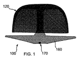
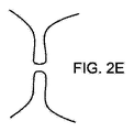
図1から3に示すように、本開示の装置100は体内の奇形または異常解剖学的構造(以下、「解剖学的構造」)の内側壁に適合して係合するような大きさに設計されたアンカー120と、当該構造に通じる開口を閉塞または覆うような大きさに設計されたカバー160とを有する。本開示の装置100は、身体のあらゆる開口を閉塞するように使用できる。その例を、様々な公知の種類の左心耳(LAA)を例示的に示す図2Aから2Dと、望ましくない開口を有する任意の種類の組織壁を示す図2Eに示す。
As shown in FIGS. 1 to 3, the
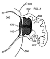
図3は、装置100により閉鎖または閉塞された、ヒトの心臓300の「吹き流し」形LAA302の断面図である。当図にはさらに、左心房306と、左上肺静脈308も示す。図において、外側アンカー側壁、または外部釣鐘型124が、LAAの内面304の渦巻き形状に適合していることが確認できる。さらに、カバー160が解剖学的構造、この例では心房内部306の表面に適合しており、最終的に生体組織により覆われることが確認できる。
FIG. 3 is a cross-sectional view of a "windsock" LAA 302 of a
装置100は、設置用ケーブル180(図15に示す)に取り付けられ、カテーテル182に挿入されて、設置、または除去される。LAAの例では、カテーテルが脚の静脈に沿って送られ、心房中隔の経中隔穿刺を通じて左心房内へと送られる、あるいはその他方法で当該部位に送られる。ピッグテールカテーテルを使用して、LAAに穴をあけるリスクを低減できる。当分野では公知のように、装着済みデリバリーカテーテルをこのピッグテールを介してLAAに送ることができる。装着済みデリバリーカテーテルは、アクセスシースの先端に送られ、次のようにして設置が実現される。まず装置をシース内に押し込む。そして、シースがLAAの開口に配置されたままの状態で、装置100が接続されたケーブル180を使用して、装置100を押し出す。最終位置は、経食道心エコー検査(TEE)、心臓内心エコー検査(ICE)、蛍光透視法、またはその他任意の公知の方法で確認できる。
The
同様にカテーテルを使用して、装置100が設置または除去されるその他身体構造にアクセスできる。装置100は、メッシュまたは伸縮可能な弾性材料で構成される。図示の実施形態では、形状記憶ワイヤの撚糸により、メッシュが形成される。あるいは、当該材料のシートに穴を打ち抜くことで装置100を形成してもよい。カテーテル内で、装置100は圧縮形態となり、細長管状構造が形成される。一実施形態において、メッシュはポリマー材料から形成され、撚糸を織るようにして形成してもよいし、シートを打ち抜いて端を溶接して管状にしてもよいし、あるいは本明細書に記載の形状に成型されてもよい。編物または織物を、本明細書に記載の特定の形状に成型することで得られた管は、圧縮可能であり、体内へ送り込まれたのちに広がり、成型された形状に復元可能である。
Similarly, catheters can be used to access other body structures on which the
打ち抜きによるもの、ワイヤメッシュのいずれの場合でも、伸縮可能な弾性材料はニチノール等の形状記憶金属または合金であってもよい。ただし、非常に弾性、伸縮性に優れ、形状記憶効果によりもとの形状に復元でき、耐久性、生体適合性も十分であれば、その他材料も利用できる。具体的に利用可能な形状記憶材料としては、銅―アルミニウム−ニッケルおよびニッケルチタン合金が挙げられるが、公知又は今後開発され得る同様の特性を有するその他材料も含まれる。材料は、形状記憶金属とポリマー材料の組合せであってもよい。即ち、図示のようにニチノール糸内にポリマー繊維が組み込まれてもよい。さらに、クラッディングされた材料を使用してもよい。例えば、ニチノールの外側にプラチナ、金、その他生体適合性貴金属、あるいは他の受動性材料をクラッディングしてもよい。編物または織物を所望の最終形状に対応する型に押し込んで、選択した材料の要件に応じた所与の熱を所定時間与えることで、型形状に加熱成型することで開示の装置100の形状が得られる。
The stretchable elastic material may be a shape memory metal such as nitinol or an alloy, whether by punching or wire mesh. However, other materials can be used as long as they are extremely elastic and stretchable, can be restored to their original shape by the shape memory effect, and have sufficient durability and biocompatibility. Specific available shape memory materials include copper-aluminum-nickel and nickel-titanium alloys, but also include other materials with similar properties that may be known or developed in the future. The material may be a combination of shape memory metal and polymer material. That is, the polymer fibers may be incorporated into the nitinol yarn as shown. In addition, cladding materials may be used. For example, platinum, gold, other biocompatible precious metals, or other passive materials may be cladding on the outside of nitinol. By pushing the knit or woven fabric into a mold corresponding to the desired final shape and applying a given heat according to the requirements of the selected material for a predetermined time, the shape of the
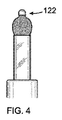
各種実施形態では、装置100の管状構造102(図32A)は、両端が開放している、あるいは一端または両端が閉じている。図示の実施形態では、織材料の各端が閉じている。カテーテルから最初に体内へと排出される先端132では、織材料をまとめて球122にしている。但し、別の方法で端部を閉じてもよい。例えば、接着、ろう付け、はんだ付け、溶着、縫合、またはクリップやジッパーの使用などが考えられる。装置100の基端では、材料はまとめられてコネクタ170に取り付けられる。これにより、装置100が設置用ケーブル180に着脱可能に接続される。取付け手段は、ネジやツイストロック等任意のもので実現でき、例えば、生体適合性金属またはプラスチック材料で製造できる。まとめて球にした先端132により、生体組織に孔をあける可能性が抑えられる。一実施形態において、コネクタ170は装置100に接続される雌ネジ部と、それに螺合する、ケーブル180の端に設けられた雄ネジ部とを含む。コネクタ170により、ケーブル180が装置100をシースから解剖学的構造内へと押し出されることを可能とする。そして、コネクタ170の螺合を解除することで、装置100を取り外すことができる。必要に応じて、ケーブル180を再度コネクタ170と螺合させてもよい。これにより、ケーブル180を引くことで、身体から装置100を除去できる。
In various embodiments, the tubular structure 102 (FIG. 32A) of
設置用ケーブル180により、カテーテル182を通じて装置100が押し出される。そのため、装置100はその際に崩れないよう十分に頑強で、かつケーブル180が装置100を通過可能とするような材料で形成される必要がある。カテーテル182から装置100の各部位が分離する際、形状記憶金属の形状記憶機能により、図や本明細書で説明するとおり、所定の形状が形成できる。
The
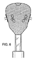
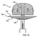
図4に示す、先端132の球122は、カテーテル180から最初に排出される部分である。装置100の織構造が全体的に圧縮されることで、カテーテル内に装置100が嵌入可能であることが確認されよう。図5および6に示すように、装置100は、形状記憶合金の弾力性の、ばね的な性質により、自動的に展開するようになっている。メッシュはカテーテルから排出されると展開可能であり、この自動展開としてまずはバルーン状構造が形成される。図7では、縁が現れ、アンカー120の外部釣鐘型124の全体的な輪郭がはっきりしてきている。図7に示すように、釣鐘型構造は中空状であり、単一の壁で画定されている。図8では、下縁130が自動的に捲れて、内部釣鐘型126が外部釣鐘型124内に形成されている。図9に示されるように、内部釣鐘型126が外部釣鐘型124に当接、補強する。これにより、中空二重壁釣鐘型アンカー120が形成されるのである。内部釣鐘型126は、外部釣鐘型124の内側に適合して係合する。これにより、解剖学的構造の生体組織に適合して係合した外部釣鐘型が固定される。
The
図10に示すように、カバー160の構造がカテーテル182から排出されて、展開し始める。管状コネクタ128は、内部釣鐘型126の頂点における、装置100の先端132からカバー120まで延在する。図11に示すように、カバー120並びにアンカー160は、展開時にまずバルーン状構造となる、二重層により形成される。図12に示すように、カバー先端面および基端面162および164がそれぞれ形成され始める。図13において、カバー160は最終的な二重層、二重プレート形状構造となっている。図15は、アンカー120に隣接するカバー160の先端面が略平坦である状態を示す斜視図である。但し、具体的に閉塞する解剖学的構造に合わせて、当該面は湾曲してもよい。さらに、具体的な解剖学的構造を覆うのに最も適したその他形状が形成されてもよい。例えば凹部168を形成することで、カバー基端面164をカバー先端面162から離間するようにしてもよい。これにより、カバー先端面が生体組織に密着した状態で、外側カバー縁166を生体組織に強く弾性的に押し付けることができる。
As shown in FIG. 10, the structure of the
実施形態において、少なくともカバー基端面164が組織増殖因子でコーティングされてもよい。これにより、カバー160がより体内で一体化し、装置100がより効果的に体内に固定され、血栓形成の可能性をさらに低減できる。当該増殖因子で装置100全体をコーティングする、または増殖因子を装置100の形状記憶材料にコーティングに一体化させることが有利であり得る。これにより、時間と共に徐々に当該因子が放出され得る。装置100の一部または全体を、その他物質でコーティングしてもよい。その他物質の例としては、血液稀釈剤、抗生物質、薬剤、または他の治療物質が挙げられる。装置100は、例えばポリエチレンテレフタレート(PET)またはその他生体適合性材料等によるポリマー織物のような、柔軟な織物で被覆してもよい。これは、装置100のメッシュの開口よりも微細な粒子をフィルタリングして、解剖学的構造に対して侵入または離脱することを防ぐことが望ましい場合に有利である。同様に、装置100をナノ材料で被覆してもよい。
In embodiments, at least the cover
さらに/あるいは、プラチナまたは金等のナノ材料、あるいはその他受動材料を使用して、閉塞装置をコーティングしてもよい。これらコーティングでは、各ワイヤを蒸着技術またはナノ積層技術でコーティングする。したがって、装置100の個別のワイヤまたは繊維が肉薄または極薄材料層でコーティングされる。
In addition / or nanomaterials such as platinum or gold, or other passive materials may be used to coat the occlusion device. In these coatings, each wire is coated with a thin film deposition technique or a nanolamination technique. Therefore, the individual wires or fibers of
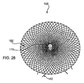
図25および26に示す実施形態では、ポリマーフィルタリング用繊維フィルタ178が、カバー基端および先端面162および164の間に挿入されている。したがって、解剖学的構造内の血栓または粒子の血流への移動が、より効果的に防止されている。フィルタ178は、面162および164の間で位置が固定されている場合、コネクタ170に取り付けて定位置に保持してもよいし、あるいは少なくとも設置前まで、定位置に縫合または接着されていてもよい。フィルタ178は、例えばPET布を含む、設置時に圧縮可能で、所望のメッシュまたは孔サイズを有するあらゆる生体適合性材料により製造可能である。
In the embodiments shown in FIGS. 25 and 26, a polymer
図14および15では、設置用ケーブル180は巻線を棒状にしたものとして示されているが、あらゆる公知の構造を採用可能であることを付言しておく。ケーブル180は、軸周りで回転して、設置用ケーブル180に取り付けられたケーブル嵌合コネクタ部170を、装置嵌合コネクタ部170からネジを緩めるようにして、あるいはその他方法で着脱可能とする。
In FIGS. 14 and 15, the
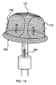
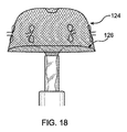
図15において、装置100は再度捕集され、カテーテル182内に回収される初期段階にある。ここでは、カバー基端面164に歪みがいくつか生じている。回収は、単一の処置中に、装置100を再配置するために実施できるし、ある程度時間が経過した後に装置100を除去するためにも実施できる。図16において、カテーテル182の端部に収縮圧力がかけられている。その結果カバー160が伸びて再びバルーン形状となり、図17ではカテーテル内に収まっている。図18では、内部釣鐘型126が外部釣鐘型124から引き離され、カテーテル182内に引きずり込まれている。図19では、内部釣鐘型126が反転して、外部釣鐘型124とともにバルーン形状を形成する。図21および22において、内部釣鐘型126がカテーテル182に引きずり込まれて、最終的に図22示すように、外部釣鐘型124がカテーテル182に引きずり込まれる。これにより、見えるのはクリップ122のみとなる。引き続き設置用ケーブル180をカテーテル182から引き出すことで、体内から装置100を完全に除去できる。
In FIG. 15, the
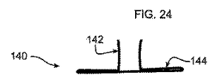
これら図に示されるように、さらには図23および24に示すように、アンカー120にはフック140が取り付けられている。なお、図示し、本明細書で説明するとおり、アンカー120を挿入先である解剖学的構造の内壁に対して外側に押し付けて、内面に弾性的に密着させることで、生体組織に対して固定的に取り付けることができる。したがって、フック140は必須要素ではないが、装置100が脱落して栓塞を起こすことをより効果的に防止するために適宜使用され得る。フック140は、アンカー120の外部釣鐘型124表面に対して傾斜して突出するかかり部142を有する。これにより、アンカー120が体内で展開して最終適合形状になる際に、フック140を生体組織内に挿入できる。
As shown in these figures, and further as shown in FIGS. 23 and 24, the
平坦部144は、図14および27に示すように(その他図では、見易さのために省略)、縫合糸176を使用して外部釣鐘型124に縫い付けられるまたはその他方法で取り付けられる。これにより、設置後、装置100の表面に対する特定の傾斜配置が維持される。アンカー120が打ち抜き形成される場合、かかり142を曲げて必要な角度にすることができる。かかり142は、平坦部144に弾性的に取り付けられる。これにより、装置100がカテーテル182を介して設置、除去される際に、かかり142が畳まれて平坦部144に沿って平坦となるようにできる。図23および24に示すフック構造の具体的構造は、フックを形成して、装置100のメッシュ材料に取り付ける一例を示すものである。フックまたはかかりのその他形状や形態も当分野では公知であり、本開示の装置100に使用できる。さらに、使用する場合にはフック140の数は具体的な設置要件に応じて変更できる。例えば、ポリエチレンテレフタレート(PET)、ポリプロピレンまたはポリテトラフルオロエチレン(PTFE)により取付構造を実現可能である。
The
本開示のアンカー120は、釣鐘型であり、その設置時の直径に対して、数分の一まで圧縮できるので、多様な直径の解剖学的構造に対して適合し、固定して取り付けることができる。具体的には、アンカー120は細長側壁により底部が解放した釣り鐘型となるため、解剖学的構造内部の、生体組織の形状に対して、細長側壁が歪むことなく密着しやすくなっている。多様に圧縮できることでさらに、特に心臓内での生体組織の大きな動きが生じても、内側壁に対する係合が維持されることを保証できる。LLAを閉塞する場合、例えば典型的な生体構造では、外部釣鐘型124は約18mmから約36mmの直径を有してもよい。装置毎に生体組織の多様な直径に対応可能であるが、理想的な装着のため、外部釣鐘型124は例えば18mm、20mm、22mm、24mm、26mm、28mm、30mm、32mm、34mm、36mmのように2mm刻みで大きくするようにしてもよい。生体組織に対して装置100が押し付けられていない状態で、内部釣鐘型126は、外部釣鐘型124よりも2mm程度直径が少ないため、16mm、18mm、20mm、22mm、24mm、26mm、28mm、30mm、32mm、34mmのような大きさとなる。
The
さらに、多様に圧縮できることで、解剖学的構造が経時的に内径を大きく変化させても、適合可能となる。フック140を使用しない実施形態では、多様な弾性と、組織に対する広い接触表面積により、装置100は非外傷性となり得る。さらに装置100の接触領域が広いことで、生体組織に対する強固な密着を実現するために、必要以上にサイズを大きくする必要がないので、具体的には心臓内のように、連続的に動くような生体組織でも、裂傷を防止できる。さらに、多様に圧縮できることで、装置100のサイズ範囲は小さくとどめる必要がある。装置100の展開時の直径サイズは、閉塞される解剖学的構造の直径の範囲に応じて決定される。LAAの閉塞の場合、例えば装置100は展開時直径が21から33mmの間で一以上となり、例えば9−Frから14−Frカテーテルが使用される。
In addition, the ability to compress in a variety of ways makes it adaptable even if the anatomical structure changes significantly over time. In embodiments where the
二層のメッシュで形成されたカバー160も弾性を有し、外側の解剖学的構造、または解剖学的構造の入り口に適合するように、大きく圧縮、変形可能である。具体的には、カバー先端面162は、組織表面に接触し、その形状に適合することができ、カバー先端面162から離間したカバー基端面164は、カバー先端面162に対して圧縮力を付与してその形状を維持できる。
The
装置100が、開口部が1mm未満の目の細かいメッシュとして形成されるため、身体に対して強固に密着でき、織物で覆われているか否かを問わずに設置直後からフィルタとして機能できる。さらに、メッシュ構造は圧力が均等に拡散されるように生体組織に接触するので、外傷を抑えながら生体組織に対してより強く密着できる。開口の大きさは、装置100のメッシュを形成するワイヤのピッチ幅、ピッチ角度に応じて決まる。これら要素は、編構造完成時に、例えば1mm未満の所期の開口サイズのメッシュを形成するよう予め決められてもよい。これにより、メッシュは非常にコンパクトとなり、解剖学的構造の腔内のあらゆる血栓を保持できる。
Since the
アンカー120とカバー160を別体として形成した装置100により、アンカー120が独自で多様な内部構造に対して圧縮、適合可能で、一方管状コネクタ128によりアンカー120から離間したカバー160が最大径に展開された状態を維持して、解剖学的構造への開口を完全に被覆できる。さらに、管状コネクタ128は非常に可撓性が高いため、カバー160が解剖学的構造の外側、または入り口の生体組織に密着するように、アンカー120の設置角度とは独立した角度に曲げることができる。
The
外部釣鐘型124と内部釣鐘型126の相互作用で、装置100が体内でずれないように、スナップフィットまたはロックボタンを実現できる。具体的には、特に何らかの理論に限定されるものではないが、外部釣鐘型124は非常に可撓性の高い、変形可能なバルーン形状を保ったままで、解剖学的構造の内面に適合して係合する。内部釣鐘型126が外部釣鐘型124に適合した記憶形状に広がると、内外の釣り鐘型の記憶形状が完成して、外部釣鐘型124が適合構成に固定される。記憶形状に復元されると、それ以上は変化しないようになる。特に記憶された形状を逸脱するような、コネクタ170の基端と先端132との間で延在する長手軸に沿ったずれによる変化は防止される。これにより、外部釣鐘型124による生体組織表面上の回転や、その他動きが防止される。さらに、内部釣鐘型126から外部釣鐘型124に付与される力により、外部釣鐘型124の現行の適合構成が強固となり、生体組織に対する外部釣鐘型124のずれがより効果的に防止される。
By the interaction of the
例えば図2Eに示すような種類の組織壁322の開口または間隙320を閉塞する場合、装置100は図28に示すように、カバー160とアンカー120とをそれぞれ壁の反対側に配置して設置できる。アンカー120は、下縁130を先端132に向けてずらすことで圧縮され、これによりカバー160が壁320の反対側に向けて圧縮される。
For example, when closing the opening or
本発明者らは、アンカー120を釣鐘構造として、左心房内で定位置に維持されたプレート形状に接続し、協働することが有利であると発見したが、装置100は身体のその他部位、即ち左心房以外の解剖学的構造において、当該部位により適した異なる構成の釣り鐘形状を有してもよい。例えば、身体のその他部位において形成可能な別の構造としては、別のプレート形状構造120A(図29)、例えば概して球形、卵形、または梨型のバルーン形状120B(図30)、あるいは反転した釣鐘型状(図31)を形成してもよい。
The present inventors have found that it is advantageous to connect the
本発明者はさらに、装置100の二層構造102A、102B、102C(図32B、33)を採用することで、カテーテル内および体内への押出性が向上して、ねじれに対する抵抗や、所期の展開後の形状のより効果的な維持を実現できることを発見した。二層により、設置後の解剖学的構造を所望どおりに塞ぐ、あるいは閉塞するように径方向強度の向上や、表面密度の向上が図られ、さらに組織成長用の効果的な基礎が実現される。
The present inventor further adopts the two-
図32Aは、単層管状構造102を示し、図32Bは折りたたまれて二層構造となった管状構造102Aを示す。そして図32Cに示すように、この二重層構造を形成し、展開後の形状が、本明細書の別箇所で説明したようにして形成される。
FIG. 32A shows a single-layer
装置100のメッシュを形成するワイヤの直径または厚さは、患者の体形、埋め込み部位、対象解剖学的構造、及び所要の強度に合わせて選択可能である。図示および本明細書記載の特性を有する装置100が実現できるようなワイヤの厚さで、本開示を実施できる。非限定的な一実施形態において、ワイヤは144打ち医療用ブレーダーに適するように非常に細くてもよいし、72打ちブレーダーに適するようにより太いワイヤであってもよい。別の実施形態において、内層、外層をそれぞれ異なる打ち数のブレーダーで形成する。例えば、内層を72打ちで比較的厚くし、外層を144打ちでより細くしてもよい。このようにして、外層では細いワイヤを高密度で編むことで、比較的高メタルカバレッジが実現され、72打ちによる内層では、比較的大きな軸方向、径方向強度が実現され、例えばカバー160とアンカー120の形成された所期の形状が維持され、その形状が所期の位置に維持されるようになる。
The diameter or thickness of the wires forming the mesh of the
図33Aは、組紐数が少ない外部層104と、組紐数が多い内部層106とを例示的に示す。これらに二層は、端部で互いに接合される。得られた二重層構造を、本明細書に記載のとおりに、所期の形状に形成する(例えば、図32Cに示す)。図33Bは、層を反対にした状態を示す。即ち、外部層106の組紐数が少なくなっている。本名所に記載の二重層構造は、これ以外にも本明細書で記載するように、形成される。
FIG. 33A schematically shows an
組紐サイズが異なる内部および外部表面は、公知の方法により、繋ぎ目で接合できる。公知の方法としては、溶接、ろう付け、はんだ付け、ウィービング、プレス加工、ピンチング加工、圧着、編み込み、その他が挙げられる。両層が同じ組紐サイズであれば、編み込み材料の一部を部分的に内側に捲るまたは折り畳むことで、または編込管の一部、例えば半分を裏返しにするようにして、内部層を形成可能である。金属編物または織物の二重構造は、閉塞が必要な多様な解剖学的構造に対応するように、所期の可変奥行きおよび幅を有すように、展開構造が形成されることを含む、本明細書記載の各種特性を実現しやすくする。当該解剖学的構造の例は、神経学的処置、心血管処置、抹消器官処置、およびその他器官の処置等の、各種解剖学的標示で確認される。 The inner and outer surfaces of different braid sizes can be joined at seams by known methods. Known methods include welding, brazing, soldering, weaving, pressing, pinching, crimping, weaving, and the like. If both layers are the same braid size, the inner layer can be formed by partially rolling or folding some of the braided material inward, or by turning part of the braided tube, eg half, inside out. Is. The double structure of a metal knit or woven fabric comprises the formation of an unfolded structure to have the desired variable depth and width to accommodate a variety of anatomical structures that require closure. Make it easier to realize the various characteristics described in the specification. Examples of such anatomical structures are identified by various anatomical markings such as neurological procedures, cardiovascular procedures, peripheral organ procedures, and other organ procedures.
本稿に引用された全ての文献は、参照によりその全体が本願に明示的に組み込まれる。当業者であれば、本開示が本稿に特に示されたものや説明されたものに限定されないことが理解されよう。また、別途規定のない限り、添付の図面の縮尺は原寸に比例していない。本開示に対して多くの異なる特徴があり、これらの特徴は一緒に用いられても、別々に用いられてもよいと考えられる。したがって、本開示は、特徴の任意の組合せや本開示における特定の適用例に限定されるべきではない。さらに、当業者であれば、本開示の範囲において変更や変形が可能であることが理解されよう。したがって、本開示の範囲に含まれる本稿の開示から当業者が容易に到達可能な全ての適切な変形例は、本開示のさらなる実施形態として含まれる。 All references cited in this article are expressly incorporated herein by reference in their entirety. Those skilled in the art will appreciate that this disclosure is not limited to what is specifically presented or described in this article. Also, unless otherwise specified, the scale of the attached drawings is not proportional to the actual size. There are many different features to the present disclosure, and it is believed that these features may be used together or separately. Therefore, the present disclosure should not be limited to any combination of features or specific applications in the present disclosure. Further, those skilled in the art will appreciate that changes and modifications can be made within the scope of the present disclosure. Accordingly, all suitable variations easily reachable by those skilled in the art from the disclosures of this document within the scope of this disclosure are included as further embodiments of the present disclosure.
Claims (11)
形状記憶合金のメッシュで形成され、カテーテル内から前記開口に送られるよう圧縮可能な少なくとも一つの細長弾性管を備え、当該管は前記カテーテルから排出されると自動展開して、
外部釣鐘型構造と、
前記外部釣鐘型構造内に配置され、前記外部釣鐘型構造の内側に適合して係合する内部釣鐘型構造とが連続的に順次形成され、前記内部釣鐘型構造及び前記外部釣鐘型構造は一緒に中空の釣鐘内部を定める単一の二重壁釣鐘型構造を形成し、
さらに、前記二重壁釣鐘型構造よりも小さい直径を有し、前記二重壁釣鐘型構造の頂点から離間する方向に前記中空の釣鐘内部を通って延在する管状コネクタと、
内部プレート形状構造と、
前記内部プレート形状構造に隣接して、前記管状コネクタによって前記二重壁釣鐘型構造から離間する二重壁プレート形状構造を形成する外部プレート形状構造と、
着脱可能コネクタとが連続的に順次形成され、
前記二重壁プレート形状構造は、前記二重壁釣鐘型構造よりも大きな直径を有し、当該二重壁プレート形状構造は、前記二重壁釣鐘型構造の中空の釣鐘内部から離間してその外部に配置され、
前記二重壁プレート形状構造は、前記開口の開放面に配置可能であり、前記二重壁釣鐘型構造は、前記開口の中空内部内に配置可能であり、前記二重壁プレート形状構造を前記開放面に固定する、装置。 A device that closes the opening of a living tissue having an open surface and a hollow interior.
It is made of a mesh of shape memory alloy and has at least one elongated elastic tube that can be compressed so that it can be sent from inside the catheter to the opening, and the tube automatically expands when it is discharged from the catheter.
External bell-shaped structure and
Wherein it is arranged outside bell structure, wherein the inner bell-shaped structure which engages with fit inside of the outer bell-shaped structure are continuously sequentially formed, the inner bell-shaped structure and the outer bell-shaped structure together Form a single double-walled bell-shaped structure that defines the interior of the hollow bell,
Further, a tubular connector having a diameter smaller than that of the double-walled bell-shaped structure and extending through the inside of the hollow bell-shaped structure in a direction away from the apex of the double-walled bell-shaped structure.
Internal plate shape structure and
An outer plate-shaped structure that forms a double-walled plate-shaped structure adjacent to the inner plate-shaped structure and separated from the double-walled bell-shaped structure by the tubular connector.
Detachable connectors are continuously and sequentially formed,
The double-walled plate-shaped structure has a larger diameter than the double-walled bell-shaped structure, and the double-walled plate-shaped structure is separated from the inside of the hollow bell of the double-walled bell-shaped structure. Placed outside,
The double-walled plate-shaped structure can be arranged on the open surface of the opening, the double-walled bell-shaped structure can be arranged inside the hollow interior of the opening, and the double-walled plate-shaped structure can be arranged. A device that is fixed to an open surface.
形状記憶合金のメッシュで形成され、カテーテル内から前記開口に送られるよう圧縮可能な細長弾性管を備え、当該管は前記カテーテルから排出されると自動展開して、
外部釣鐘型構造と、
前記外部釣鐘型構造内に配置され、前記外部釣鐘型構造の内側に適合して係合し、それによって単一の二重壁釣鐘型構造を形成する内部釣鐘型構造と、
前記内部釣鐘型構造よりも小さい直径を有し、前記内部釣鐘型構造の頂点から離間する方向に延在する管状コネクタとが連続的に順次形成され、前記二重壁釣鐘型構造は前記管状コネクタが通過する実質的に中空の釣鐘内部を形成し、
さらに、内部プレート形状構造と、
前記内側プレート形状構造に隣接して単一の二重壁プレート形状構造を形成する外部プレート形状構造と、
着脱可能コネクタとが連続的に順次形成され、
前記二重壁プレート形状構造は、前記二重壁釣鐘型構造よりも大きな直径を有し、前記管状コネクタによって前記二重壁釣鐘型構造から離間しかつ前記二重壁釣鐘型構造の内部に配置されず、前記二重壁プレート形状構造と前記二重壁釣鐘型構造との間に間隙が形成される、装置。 A device that closes the opening of living tissue
It is made of a mesh of shape memory alloy and has an elongated elastic tube that can be compressed so that it can be sent from inside the catheter to the opening, and the tube automatically expands when it is discharged from the catheter.
External bell-shaped structure and
Disposed within outer bell-shaped structure, and the engagement and fit inside of the outer bell-shaped structure, whereby the internal bell-shaped structure to form a single double-walled bell-shaped structure,
Tubular connectors having a diameter smaller than that of the internal bell-shaped structure and extending in a direction away from the apex of the internal bell-shaped structure are continuously and sequentially formed, and the double-walled bell-shaped structure is the tubular connector. Forming a virtually hollow bell through which
In addition, the internal plate shape structure and
An outer plate-shaped structure that forms a single double-walled plate-shaped structure adjacent to the inner plate-shaped structure ,
Detachable connectors are continuously and sequentially formed ,
The double-walled plate-shaped structure has a larger diameter than the double-walled bell-shaped structure, is separated from the double-walled bell-shaped structure by the tubular connector, and is arranged inside the double-walled bell-shaped structure. A device in which a gap is formed between the double-walled plate-shaped structure and the double-walled bell-shaped structure.
Applications Claiming Priority (3)
| Application Number | Priority Date | Filing Date | Title |
|---|---|---|---|
| US201662309578P | 2016-03-17 | 2016-03-17 | |
| US62/309,578 | 2016-03-17 | ||
| PCT/US2017/022986 WO2017161283A1 (en) | 2016-03-17 | 2017-03-17 | Occluding anatomical structures |
Publications (3)
| Publication Number | Publication Date |
|---|---|
| JP2019511345A JP2019511345A (en) | 2019-04-25 |
| JP2019511345A5 JP2019511345A5 (en) | 2020-04-23 |
| JP6937327B2 true JP6937327B2 (en) | 2021-09-22 |
Family
ID=59851299
Family Applications (1)
| Application Number | Title | Priority Date | Filing Date |
|---|---|---|---|
| JP2018568178A Active JP6937327B2 (en) | 2016-03-17 | 2017-03-17 | Anatomical blockage |
Country Status (5)
| Country | Link |
|---|---|
| US (1) | US11253261B2 (en) |
| EP (1) | EP3429479A4 (en) |
| JP (1) | JP6937327B2 (en) |
| CN (1) | CN109069160B (en) |
| WO (1) | WO2017161283A1 (en) |
Families Citing this family (57)
| Publication number | Priority date | Publication date | Assignee | Title |
|---|---|---|---|---|
| JP6423851B2 (en) | 2013-03-13 | 2018-11-14 | アーロン・ヴィ・カプラン | Device for emptying the left atrial appendage |
| US11399842B2 (en) | 2013-03-13 | 2022-08-02 | Conformal Medical, Inc. | Devices and methods for excluding the left atrial appendage |
| US11154302B2 (en) | 2014-03-31 | 2021-10-26 | DePuy Synthes Products, Inc. | Aneurysm occlusion device |
| US11076860B2 (en) | 2014-03-31 | 2021-08-03 | DePuy Synthes Products, Inc. | Aneurysm occlusion device |
| EP3134010B1 (en) | 2014-04-25 | 2020-04-22 | Flow Medtech, LLC | Left atrial appendage occlusion device |
| ES2732752T3 (en) | 2014-04-30 | 2019-11-25 | Cerus Endovascular Ltd | Occlusion device |
| EP3193790A4 (en) | 2014-09-19 | 2018-10-03 | Flow Medtech, Inc. | Left atrial appendage occlusion device delivery system |
| CA2976260C (en) | 2015-02-25 | 2024-02-06 | Galaxy Therapeutics, Llc | System for and method of treating aneurysms |
| JP6892188B2 (en) | 2015-12-07 | 2021-06-23 | シーラス エンドバスキュラー リミテッド | Blocking device |
| EP3782576A1 (en) | 2016-03-11 | 2021-02-24 | Cerus Endovascular Limited | Occlusion device |
| US11026695B2 (en) | 2016-10-27 | 2021-06-08 | Conformal Medical, Inc. | Devices and methods for excluding the left atrial appendage |
| US11426172B2 (en) | 2016-10-27 | 2022-08-30 | Conformal Medical, Inc. | Devices and methods for excluding the left atrial appendage |
| MX2019010041A (en) | 2017-02-23 | 2020-01-13 | Depuy Synthes Products Inc | Aneurysm device and delivery system. |
| CN108938034A (en) * | 2017-05-23 | 2018-12-07 | 杭州诺茂医疗科技有限公司 | A kind of occluder for left auricle and preparation method thereof for improving sealing effect |
| US11812971B2 (en) | 2017-08-21 | 2023-11-14 | Cerus Endovascular Limited | Occlusion device |
| EP3459469A1 (en) | 2017-09-23 | 2019-03-27 | Universität Zürich | Medical occluder device |
| EP4338688A3 (en) * | 2017-12-18 | 2024-05-22 | Boston Scientific Scimed, Inc. | Occlusive device with expandable member |
| US11185335B2 (en) | 2018-01-19 | 2021-11-30 | Galaxy Therapeutics Inc. | System for and method of treating aneurysms |
| US10905430B2 (en) | 2018-01-24 | 2021-02-02 | DePuy Synthes Products, Inc. | Aneurysm device and delivery system |
| WO2019178579A1 (en) * | 2018-03-16 | 2019-09-19 | Boston Scientific Scimed, Inc. | Devices for vein closure |
| EP3552556A1 (en) * | 2018-04-11 | 2019-10-16 | Occlutech Holding AG | Vascular implant with anchor member |
| EP3787525A4 (en) * | 2018-05-02 | 2022-06-22 | Conformal Medical, Inc. | Devices and methods for excluding the left atrial appendage |
| US11596412B2 (en) | 2018-05-25 | 2023-03-07 | DePuy Synthes Products, Inc. | Aneurysm device and delivery system |
| US11058430B2 (en) | 2018-05-25 | 2021-07-13 | DePuy Synthes Products, Inc. | Aneurysm device and delivery system |
| CN112566566A (en) * | 2018-07-06 | 2021-03-26 | 波士顿科学医学有限公司 | Closed medical device |
| US11051825B2 (en) | 2018-08-08 | 2021-07-06 | DePuy Synthes Products, Inc. | Delivery system for embolic braid |
| US11123077B2 (en) | 2018-09-25 | 2021-09-21 | DePuy Synthes Products, Inc. | Intrasaccular device positioning and deployment system |
| US11076861B2 (en) | 2018-10-12 | 2021-08-03 | DePuy Synthes Products, Inc. | Folded aneurysm treatment device and delivery method |
| US11406392B2 (en) | 2018-12-12 | 2022-08-09 | DePuy Synthes Products, Inc. | Aneurysm occluding device for use with coagulating agents |
| US11272939B2 (en) | 2018-12-18 | 2022-03-15 | DePuy Synthes Products, Inc. | Intrasaccular flow diverter for treating cerebral aneurysms |
| US11134953B2 (en) | 2019-02-06 | 2021-10-05 | DePuy Synthes Products, Inc. | Adhesive cover occluding device for aneurysm treatment |
| US20200253614A1 (en) | 2019-02-08 | 2020-08-13 | Conformal Medical, Inc. | Devices and methods for excluding the left atrial appendage |
| US11337706B2 (en) | 2019-03-27 | 2022-05-24 | DePuy Synthes Products, Inc. | Aneurysm treatment device |
| US11413046B2 (en) | 2019-05-21 | 2022-08-16 | DePuy Synthes Products, Inc. | Layered braided aneurysm treatment device |
| US11672542B2 (en) | 2019-05-21 | 2023-06-13 | DePuy Synthes Products, Inc. | Aneurysm treatment with pushable ball segment |
| US11602350B2 (en) | 2019-12-05 | 2023-03-14 | DePuy Synthes Products, Inc. | Intrasaccular inverting braid with highly flexible fill material |
| JP2020189093A (en) * | 2019-05-21 | 2020-11-26 | デピュイ・シンセス・プロダクツ・インコーポレイテッド | Layered braided aneurysm treatment device |
| US11278292B2 (en) | 2019-05-21 | 2022-03-22 | DePuy Synthes Products, Inc. | Inverting braided aneurysm treatment system and method |
| US10653425B1 (en) | 2019-05-21 | 2020-05-19 | DePuy Synthes Products, Inc. | Layered braided aneurysm treatment device |
| US11497504B2 (en) | 2019-05-21 | 2022-11-15 | DePuy Synthes Products, Inc. | Aneurysm treatment with pushable implanted braid |
| US11607226B2 (en) | 2019-05-21 | 2023-03-21 | DePuy Synthes Products, Inc. | Layered braided aneurysm treatment device with corrugations |
| US10856880B1 (en) | 2019-05-25 | 2020-12-08 | Galaxy Therapeutics, Inc. | Systems and methods for treating aneurysms |
| CN112770683B (en) * | 2019-07-25 | 2022-05-31 | 清流科技有限公司 | Embolic devices for promoting blood clot formation and methods of retrieving the devices from a body lumen |
| EP3838164A1 (en) * | 2019-08-27 | 2021-06-23 | St. Jude Medical, Cardiology Division, Inc. | Deflectable torque cable for delivery of medical devices |
| CN114641242A (en) * | 2019-09-26 | 2022-06-17 | 苏黎世大学 | Left atrial appendage occlusion device |
| EP3831343B1 (en) * | 2019-12-05 | 2024-01-31 | Tendyne Holdings, Inc. | Braided anchor for mitral valve |
| US11457926B2 (en) | 2019-12-18 | 2022-10-04 | DePuy Synthes Products, Inc. | Implant having an intrasaccular section and intravascular section |
| US11534175B2 (en) * | 2020-01-28 | 2022-12-27 | Medtronic, Inc. | Modular left atrial appendage closure |
| US11406404B2 (en) | 2020-02-20 | 2022-08-09 | Cerus Endovascular Limited | Clot removal distal protection methods |
| US20210338247A1 (en) * | 2020-05-04 | 2021-11-04 | DePuy Synthes Products, Inc. | Double layer braid |
| US20220008050A1 (en) * | 2020-07-07 | 2022-01-13 | St. Jude Medical, Cardiology Division, Inc. | Devices and methods for occlusion of vascular system abnormalities |
| US11771410B2 (en) * | 2020-08-03 | 2023-10-03 | St. Jude Medical, Cardiology Division, Inc. | Devices and methods for the treatment of vascular abnormalities |
| US20220079667A1 (en) * | 2020-09-17 | 2022-03-17 | St. Jude Medical, Cardiology Division, Inc. | Left Atrial Appendage Occluder Delivery Device Incorporating Ablation Functionality |
| WO2022164957A1 (en) | 2021-01-27 | 2022-08-04 | Galaxy Therapeutics, Inc. | Systems and methods for treating aneurysms |
| US20220240911A1 (en) * | 2021-01-29 | 2022-08-04 | St. Jude Medical, Cardiology Division, Inc. | Devices and methods for the treatment of vascular abnormalities |
| EP4301240A1 (en) * | 2021-03-03 | 2024-01-10 | St. Jude Medical, Cardiology Division, Inc. | Occluder stabilizing members |
| CN116831679B (en) * | 2023-09-02 | 2023-11-14 | 杭州亿科医疗科技有限公司 | Aneurysm vortex device easy to release |
Family Cites Families (66)
| Publication number | Priority date | Publication date | Assignee | Title |
|---|---|---|---|---|
| FR912M (en) | 1960-10-12 | 1961-11-06 | ||
| US4034642A (en) | 1976-09-27 | 1977-07-12 | Rockwell International Corporation | Braiding machine |
| JPS5933085B2 (en) | 1976-12-09 | 1984-08-13 | クラレプラスチツクス株式会社 | Synthetic resin pipe manufacturing method and manufacturing equipment |
| US4372191A (en) | 1982-03-12 | 1983-02-08 | Rockwell International Corp. | Rotary braiding machine |
| US4621560A (en) | 1985-04-11 | 1986-11-11 | Atlantic Research Corporation | Method of sequenced braider motion for multi-ply braiding apparatus |
| US4753149A (en) | 1987-01-15 | 1988-06-28 | Northrop Corporation | Braiding machine |
| US4729278A (en) | 1987-05-04 | 1988-03-08 | Rockwell International Corporation | Vertical rotary braider |
| US4922798A (en) | 1988-05-09 | 1990-05-08 | Airfoil Textron Inc. | Apparatus and method for braiding fiber strands |
| US5176062A (en) | 1989-08-17 | 1993-01-05 | Maillefer Charles E | Braiding machine |
| US4934240A (en) | 1989-10-30 | 1990-06-19 | Atlantic Research Corporation | Braiding apparatus |
| GB9002741D0 (en) | 1990-02-07 | 1990-04-04 | Karg Limited | Braiding machine |
| AU662520B2 (en) | 1991-03-04 | 1995-09-07 | U.S. Composites Corp. | Asymmetric braiding of improved fiber reinforced products |
| JPH07122211B2 (en) | 1991-10-18 | 1995-12-25 | 村田機械株式会社 | Composition method of cylindrical braid structure |
| US5301596A (en) | 1992-04-03 | 1994-04-12 | Clemson University | Shuttle plate braiding machine |
| US5974938A (en) | 1992-06-02 | 1999-11-02 | Lloyd; Carter Francis | Braiding machine |
| US5562725A (en) | 1992-09-14 | 1996-10-08 | Meadox Medicals Inc. | Radially self-expanding implantable intraluminal device |
| US5476027A (en) | 1993-03-23 | 1995-12-19 | Murata Kikai Kabushiki Kaisha | Braider |
| IT1289350B1 (en) | 1995-12-22 | 1998-10-02 | Sipra Patent Beteiligung | CIRCULAR MACHINE FOR BRAID |
| US6168622B1 (en) | 1996-01-24 | 2001-01-02 | Microvena Corporation | Method and apparatus for occluding aneurysms |
| US5972019A (en) | 1996-07-25 | 1999-10-26 | Target Therapeutics, Inc. | Mechanical clot treatment device |
| US6626939B1 (en) | 1997-12-18 | 2003-09-30 | Boston Scientific Scimed, Inc. | Stent-graft with bioabsorbable structural support |
| US5944738A (en) | 1998-02-06 | 1999-08-31 | Aga Medical Corporation | Percutaneous catheter directed constricting occlusion device |
| US5925060A (en) | 1998-03-13 | 1999-07-20 | B. Braun Celsa | Covered self-expanding vascular occlusion device |
| US8377114B2 (en) | 1999-08-09 | 2013-02-19 | Cardiokinetix, Inc. | Sealing and filling ventricular partitioning devices to improve cardiac function |
| US6622604B1 (en) | 2000-01-31 | 2003-09-23 | Scimed Life Systems, Inc. | Process for manufacturing a braided bifurcated stent |
| US6468301B1 (en) | 2000-03-27 | 2002-10-22 | Aga Medical Corporation | Repositionable and recapturable vascular stent/graft |
| IL137326A0 (en) | 2000-07-17 | 2001-07-24 | Mind Guard Ltd | Implantable braided stroke preventing device and method of manufacturing |
| US6679152B1 (en) | 2000-11-28 | 2004-01-20 | Andrew A. Head | Forming ring with adjustable diameter for braid production and method of braid production |
| US6786898B2 (en) * | 2003-01-15 | 2004-09-07 | Medtronic, Inc. | Methods and tools for accessing an anatomic space |
| IL157732A0 (en) | 2001-03-08 | 2004-03-28 | Atritech Inc | Atrial filter implants |
| US20030028209A1 (en) | 2001-07-31 | 2003-02-06 | Clifford Teoh | Expandable body cavity liner device |
| US7001425B2 (en) | 2002-11-15 | 2006-02-21 | Scimed Life Systems, Inc. | Braided stent method for its manufacture |
| US7093527B2 (en) | 2003-06-10 | 2006-08-22 | Surpass Medical Ltd. | Method and apparatus for making intraluminal implants and construction particularly useful in such method and apparatus |
| US9861346B2 (en) | 2003-07-14 | 2018-01-09 | W. L. Gore & Associates, Inc. | Patent foramen ovale (PFO) closure device with linearly elongating petals |
| DE10338702B9 (en) | 2003-08-22 | 2007-04-26 | Occlutech Gmbh | Occlusioninstrument |
| US7165945B2 (en) | 2003-08-22 | 2007-01-23 | Sikorsky Aircraft Corporation | Braided spar for a rotor blade and method of manufacture thereof |
| US7275471B2 (en) | 2003-12-29 | 2007-10-02 | Surpass Medical Ltd. | Mixed wire braided device with structural integrity |
| US8777974B2 (en) | 2004-03-19 | 2014-07-15 | Aga Medical Corporation | Multi-layer braided structures for occluding vascular defects |
| US8398670B2 (en) | 2004-03-19 | 2013-03-19 | Aga Medical Corporation | Multi-layer braided structures for occluding vascular defects and for occluding fluid flow through portions of the vasculature of the body |
| US20050228434A1 (en) | 2004-03-19 | 2005-10-13 | Aga Medical Corporation | Multi-layer braided structures for occluding vascular defects |
| US9039724B2 (en) | 2004-03-19 | 2015-05-26 | Aga Medical Corporation | Device for occluding vascular defects |
| US20060025801A1 (en) | 2004-07-30 | 2006-02-02 | Robert Lulo | Embolic device deployment system with filament release |
| CA2581272A1 (en) | 2004-09-22 | 2006-05-18 | Lee R. Guterman | Cranial aneurysm treatment arrangement |
| JP5132315B2 (en) | 2004-11-05 | 2013-01-30 | タミケア リミテッド | Method and apparatus for manufacturing extensible products |
| US20060116714A1 (en) | 2004-11-26 | 2006-06-01 | Ivan Sepetka | Coupling and release devices and methods for their assembly and use |
| US7270043B2 (en) | 2005-01-25 | 2007-09-18 | Wardwell Braiding Machine Company | Powered lower bobbin feed system for deflector type rotary braiding machines |
| US8157837B2 (en) | 2006-03-13 | 2012-04-17 | Pneumrx, Inc. | Minimally invasive lung volume reduction device and method |
| DE102006013770A1 (en) | 2006-03-24 | 2007-09-27 | Occlutech Gmbh | Occlusion instrument and method for its production |
| EP1849440A1 (en) | 2006-04-28 | 2007-10-31 | Younes Boudjemline | Vascular stents with varying diameter |
| EP2056747A2 (en) | 2006-08-17 | 2009-05-13 | NFOCUS Neuromedical Inc. | Isolation devices for the treatment of aneurysms |
| DE102006040415B3 (en) | 2006-08-29 | 2008-01-24 | Peter Osypka Stiftung Stiftung des bürgerlichen Rechts | Closure element for an occlusion instrument for closing openings in a heart comprises a double-walled tubular braiding having a first braided section with a small cross-section and a second braided section surrounding the first section |
| US7500345B2 (en) | 2006-11-07 | 2009-03-10 | The Goodyear Tire & Rubber Company | Mandrel for a tubular strander |
| US7669315B2 (en) | 2006-11-07 | 2010-03-02 | The Goodyear Tire & Rubber Company | Apparatus for making a helically wound conductor |
| EP2460476B1 (en) | 2007-04-16 | 2020-11-25 | Occlutech Holding AG | Occluder for closing a cardiac auricle and manufacturing method therefor |
| US8034061B2 (en) * | 2007-07-12 | 2011-10-11 | Aga Medical Corporation | Percutaneous catheter directed intravascular occlusion devices |
| WO2009052432A2 (en) | 2007-10-19 | 2009-04-23 | Coherex Medical, Inc. | Medical device for modification of left atrial appendange and related systems and methods |
| US8151682B2 (en) | 2009-01-26 | 2012-04-10 | Boston Scientific Scimed, Inc. | Atraumatic stent and method and apparatus for making the same |
| CA2778639A1 (en) * | 2009-11-05 | 2011-05-12 | Sequent Medical Inc. | Multiple layer filamentary devices or treatment of vascular defects |
| EP2387950A1 (en) * | 2010-05-23 | 2011-11-23 | Occlutech Holding AG | Medical implant and manufacturing method thereof |
| US8828051B2 (en) * | 2010-07-02 | 2014-09-09 | Pfm Medical Ag | Left atrial appendage occlusion device |
| US8821529B2 (en) | 2011-03-25 | 2014-09-02 | Aga Medical Corporation | Device and method for occluding a septal defect |
| JP6240604B2 (en) * | 2011-08-19 | 2017-11-29 | インセプタス メディカル リミテッド ライアビリティ カンパニー | Expandable occlusion device and method |
| US9554806B2 (en) | 2011-09-16 | 2017-01-31 | W. L. Gore & Associates, Inc. | Occlusive devices |
| US8758389B2 (en) | 2011-11-18 | 2014-06-24 | Aga Medical Corporation | Devices and methods for occluding abnormal openings in a patient's vasculature |
| US8715315B1 (en) | 2013-03-15 | 2014-05-06 | Insera Therapeutics, Inc. | Vascular treatment systems |
| CN204133530U (en) * | 2014-09-29 | 2015-02-04 | 上海形状记忆合金材料有限公司 | Occluder for left auricle |
-
2017
- 2017-03-17 WO PCT/US2017/022986 patent/WO2017161283A1/en active Application Filing
- 2017-03-17 EP EP17767639.2A patent/EP3429479A4/en active Pending
- 2017-03-17 US US16/085,609 patent/US11253261B2/en active Active
- 2017-03-17 CN CN201780027306.8A patent/CN109069160B/en active Active
- 2017-03-17 JP JP2018568178A patent/JP6937327B2/en active Active
Also Published As
| Publication number | Publication date |
|---|---|
| US11253261B2 (en) | 2022-02-22 |
| US20190110796A1 (en) | 2019-04-18 |
| CN109069160B (en) | 2022-05-17 |
| CN109069160A (en) | 2018-12-21 |
| WO2017161283A1 (en) | 2017-09-21 |
| EP3429479A1 (en) | 2019-01-23 |
| JP2019511345A (en) | 2019-04-25 |
| EP3429479A4 (en) | 2019-10-23 |
Similar Documents
| Publication | Publication Date | Title |
|---|---|---|
| JP6937327B2 (en) | Anatomical blockage | |
| US20230083672A1 (en) | Occlusion devices and methods of their manufacture and use | |
| ES2536253T3 (en) | Implantable device with rolled filament | |
| US7691115B2 (en) | Occlusion device with flexible fabric connector | |
| US10813649B2 (en) | Device for closing an atrial appendage | |
| CA2965797A1 (en) | Intralumenal stent graft fixation | |
| JP7451641B2 (en) | Stent graft device having anchor member with adjustable geometry | |
| US11369499B2 (en) | Insertion and release system for implants | |
| WO2020234470A1 (en) | Occluder with stretchable waist | |
| US20220175392A1 (en) | Occluding anatomical structures | |
| CN117243660A (en) | Intracapsular neck bridging device |
Legal Events
| Date | Code | Title | Description |
|---|---|---|---|
| A521 | Request for written amendment filed |
Free format text: JAPANESE INTERMEDIATE CODE: A523 Effective date: 20200309 |
|
| A621 | Written request for application examination |
Free format text: JAPANESE INTERMEDIATE CODE: A621 Effective date: 20200309 |
|
| A131 | Notification of reasons for refusal |
Free format text: JAPANESE INTERMEDIATE CODE: A131 Effective date: 20210224 |
|
| A977 | Report on retrieval |
Free format text: JAPANESE INTERMEDIATE CODE: A971007 Effective date: 20210226 |
|
| A521 | Request for written amendment filed |
Free format text: JAPANESE INTERMEDIATE CODE: A523 Effective date: 20210524 |
|
| TRDD | Decision of grant or rejection written | ||
| A01 | Written decision to grant a patent or to grant a registration (utility model) |
Free format text: JAPANESE INTERMEDIATE CODE: A01 Effective date: 20210803 |
|
| A61 | First payment of annual fees (during grant procedure) |
Free format text: JAPANESE INTERMEDIATE CODE: A61 Effective date: 20210830 |
|
| R150 | Certificate of patent or registration of utility model |
Ref document number: 6937327 Country of ref document: JP Free format text: JAPANESE INTERMEDIATE CODE: R150 |
|
| S111 | Request for change of ownership or part of ownership |
Free format text: JAPANESE INTERMEDIATE CODE: R313113 |
|
| R350 | Written notification of registration of transfer |
Free format text: JAPANESE INTERMEDIATE CODE: R350 |