JP6936005B2 - Syringe and treatment set - Google Patents
Syringe and treatment set Download PDFInfo
- Publication number
- JP6936005B2 JP6936005B2 JP2016251619A JP2016251619A JP6936005B2 JP 6936005 B2 JP6936005 B2 JP 6936005B2 JP 2016251619 A JP2016251619 A JP 2016251619A JP 2016251619 A JP2016251619 A JP 2016251619A JP 6936005 B2 JP6936005 B2 JP 6936005B2
- Authority
- JP
- Japan
- Prior art keywords
- syringe
- hole
- outer cylinder
- discharge port
- sectional area
- Prior art date
- Legal status (The legal status is an assumption and is not a legal conclusion. Google has not performed a legal analysis and makes no representation as to the accuracy of the status listed.)
- Active
Links
Images


Landscapes
- Infusion, Injection, And Reservoir Apparatuses (AREA)
- Prostheses (AREA)
- Surgical Instruments (AREA)
Description
本発明は、シリンジおよび処置セットに関する。 The present invention relates to syringes and treatment sets.
例えば、脊椎変性すべり症・分離すべり症、脊柱管狭窄症、椎間板ヘルニア、圧迫骨折等に対する治療として、脊椎後方固定術が行われている。 For example, posterior spinal fusion is performed as a treatment for spinal degenerative spondylolisthesis / spondylolisthesis, spinal canal stenosis, herniated disc, compression fracture, and the like.
この脊椎後方固定術では、個々の椎骨にスクリューを螺合させ、これらのスクリューを上下の椎骨に跨る矯正用ロッドに結合する。これにより、上下の椎骨は、それらの離間距離が適切な大きさに保持されて固定される。その結果、神経の圧迫が除去された状態で、脊椎の安定性が確保される。 In this posterior spinal fusion, screws are screwed into the individual vertebrae and these screws are connected to an orthodontic rod that straddles the upper and lower vertebrae. As a result, the upper and lower vertebrae are fixed by maintaining their separation distance at an appropriate size. As a result, spinal stability is ensured with nerve compression removed.
このような脊椎後方固定術において、椎骨(骨)が十分な強度を有する場合には、スクリューは、直接または下穴を穿けた後に椎骨に螺合されるが、これでも椎骨とスクリューとの間に十分な結合強度を得ることができる。 In such posterior spinal fusion, if the vertebrae (bones) are strong enough, the screws are screwed into the vertebrae either directly or after drilling a pilot hole, but still between the vertebrae and the screw. Sufficient bond strength can be obtained.
しかしながら、椎骨の表面を構成する皮質骨が薄くなったり、内部の海綿骨の骨梁が細くなっている場合には、椎骨が十分な強度を有しないため、前記と同様にして椎骨にスクリューを螺合させても、椎骨とスクリューとの間で十分な固定強度が得られない場合がある。そのため、上下の椎骨同士の離間距離を適切な大きさに保つことや、そもそも脊椎後方固定術を施術することができないという問題がある。 However, if the cortical bone that constitutes the surface of the vertebra is thin or the trabecula of the cancellous bone inside is thin, the vertebra does not have sufficient strength, so a screw is applied to the vertebra in the same manner as described above. Even if screwed, sufficient fixing strength may not be obtained between the vertebra and the screw. Therefore, there are problems that the distance between the upper and lower vertebrae can be kept to an appropriate size and that posterior spinal fusion cannot be performed in the first place.
これらの問題を解消することを目的に、椎骨に形成した下穴に骨補填材(人工骨)を挿入した後、この骨補填材を介して椎骨にスクリューを螺合させる方法が提案されている(例えば、特許文献1参照)。かかる作業は、患者の負担を軽減するためにも迅速に行うことが重要である。 For the purpose of solving these problems, a method has been proposed in which a bone filling material (artificial bone) is inserted into a pilot hole formed in the vertebra and then a screw is screwed into the vertebra through the bone filling material. (See, for example, Patent Document 1). It is important that such work be performed promptly in order to reduce the burden on the patient.
本発明の目的は、例えば、椎骨(物体)に形成した下穴(欠損部)に骨補填材(流体)を迅速かつ確実に注入し得るシリンジ、および、かかるシリンジを有する処置セットを提供することにある。 An object of the present invention is, for example, to provide a syringe capable of rapidly and surely injecting a bone filling material (fluid) into a pilot hole (defective portion) formed in a vertebra (object), and a treatment set having such a syringe. It is in.
このような目的は、下記(1)〜(14)に記載の本発明により達成される。
(1) 流体を収納可能な外筒と、
前記外筒の先端部から突出し、前記流体を排出する排出口と、
前記外筒内に摺動可能に設けられたガスケットと、
軸方向に沿って形成された貫通孔を備え、前記ガスケットを前記外筒内で移動操作するプランジャとを有することを特徴とするシリンジ。
Such an object is achieved by the present invention described in the following (1) to (14).
(1) An outer cylinder that can store fluid and
A discharge port that protrudes from the tip of the outer cylinder and discharges the fluid,
A gasket provided so as to be slidable in the outer cylinder, and
A syringe comprising a through hole formed along the axial direction and a plunger for moving and operating the gasket in the outer cylinder.
これにより、シリンジを案内する長尺部材とともに使用することが可能となり、物体の欠損部に流体を迅速かつ確実に注入することができる。 This makes it possible to use it together with a long member that guides the syringe, and the fluid can be quickly and surely injected into the defective portion of the object.
(2) 前記貫通孔の中心軸と前記排出口の中心軸とがほぼ一致している上記(1)に記載のシリンジ。 (2) The syringe according to (1) above, wherein the central axis of the through hole and the central axis of the discharge port substantially coincide with each other.
これにより、長尺部材とともに使用する場合には、長尺部材を貫通孔および排出口により容易かつ迅速に挿通することができる。 Thereby, when used together with the long member, the long member can be easily and quickly inserted through the through hole and the discharge port.
(3) 前記排出口の中心軸と前記外筒の中心軸とがほぼ一致している上記(1)または(2)に記載のシリンジ。 (3) The syringe according to (1) or (2) above, wherein the central axis of the discharge port and the central axis of the outer cylinder substantially coincide with each other.
これにより、長尺部材とともに使用する場合には、長尺部材を貫通孔および排出口により容易かつ迅速に挿通することができる。 Thereby, when used together with the long member, the long member can be easily and quickly inserted through the through hole and the discharge port.
(4) 前記プランジャは、長尺のプランジャ本体を備え、
前記プランジャ本体の横断面積をX[mm2]とし、前記貫通孔の横断面積をY[mm2]としたとき、X/Yが3以上200以下である上記(1)ないし(3)のいずれかに記載のシリンジ。
(4) The plunger is provided with a long plunger body.
When the cross-sectional area of the plunger body is X [mm 2 ] and the cross-sectional area of the through hole is Y [mm 2 ], X / Y is 3 or more and 200 or less. The syringe described in Crab.
これにより、プランジャ本体の機械的強度が低下するのを防止しつつ、長尺部材とともに使用する場合には、長尺部材を挿通するのに十分なサイズの貫通孔を確保することができる。 As a result, it is possible to secure a through hole having a size sufficient for inserting the long member when the plunger body is used together with the long member while preventing the mechanical strength of the plunger body from being lowered.
(5) 前記外筒は、筒状の本体と、該本体の先端部に螺合により装着され、前記排出口が接続された蓋体とを備える上記(1)ないし(4)のいずれかに記載のシリンジ。 (5) The outer cylinder is any one of (1) to (4) above, comprising a cylindrical main body and a lid body screwed to the tip of the main body and to which the discharge port is connected. The syringe described.
蓋体が本体に螺合により装着されることで、外筒内の流体へ付与される圧力が大きい場合でも、本体から離脱し難い。このため、流体を欠損部に確実に注入することができる。 Since the lid is attached to the main body by screwing, it is difficult to separate from the main body even when the pressure applied to the fluid in the outer cylinder is large. Therefore, the fluid can be reliably injected into the defect portion.
(6) 当該シリンジは、前記貫通孔および前記排出口に、長尺部材を挿通した状態で使用される上記(1)ないし(5)のいずれかに記載のシリンジ。
これにより、長尺部材を利用してシリンジを前進させることができる。
(6) The syringe according to any one of (1) to (5) above, wherein the syringe is used with a long member inserted through the through hole and the discharge port.
As a result, the syringe can be advanced by using the long member.
(7) 前記長尺部材を前記貫通孔および前記排出口に挿通した際に、前記ガスケットは、前記長尺部材により刺通された状態となり、この状態で前記長尺部材の外面に密着する上記(6)に記載のシリンジ。 (7) When the long member is inserted into the through hole and the discharge port, the gasket is in a state of being pierced by the long member, and in this state, the gasket is in close contact with the outer surface of the long member. The syringe according to (6).
これにより、プランジャを操作してガスケットを先端方向に向かって移動させても、外筒内の流体が貫通孔に入り込むことが阻止される。 As a result, even if the plunger is operated to move the gasket toward the tip end, the fluid in the outer cylinder is prevented from entering the through hole.
(8) 前記貫通孔の横断面積をY[mm2]とし、前記長尺部材の横断面積をZ[mm2]としたとき、Y/Zが1.1以上200以下である上記(6)または(7)に記載のシリンジ。
これにより、長尺部材を円滑に貫通孔に挿通することができる。
(8) When the cross-sectional area of the through hole is Y [mm 2 ] and the cross-sectional area of the long member is Z [mm 2 ], Y / Z is 1.1 or more and 200 or less (6). Or the syringe according to (7).
As a result, the long member can be smoothly inserted into the through hole.
(9) 前記長尺部材の横断面積をZ[mm2]とし、前記排出口の内腔部の横断面積をW[mm2]としたとき、W/Zが1.5以上200以下である上記(6)ないし(8)のいずれかに記載のシリンジ。 (9) When the cross-sectional area of the long member is Z [mm 2 ] and the cross-sectional area of the lumen of the discharge port is W [mm 2 ], W / Z is 1.5 or more and 200 or less. The syringe according to any one of (6) to (8) above.
これにより、長尺部材を排出口に挿通した状態でも、外筒内から流体を円滑に排出することができる。 As a result, the fluid can be smoothly discharged from the outer cylinder even when the long member is inserted into the discharge port.
(10) 前記長尺部材は、ガイドワイヤである上記(6)ないし(9)のいずれかに記載のシリンジ。 (10) The syringe according to any one of (6) to (9) above, wherein the long member is a guide wire.
(11) 物体の欠損部に流体を注入するのに使用される処置セットであって、
上記(1)ないし(10)のいずれかに記載のシリンジと、
前記貫通孔および前記排出口に挿通され、前記シリンジの前記排出口を前記欠損部またはその近傍に案内する長尺部材とを有することを特徴とする処置セット。
これにより、物体の欠損部に流体を迅速かつ確実に充填することができる。
(11) A set of treatments used to inject fluid into a defect in an object.
With the syringe according to any one of (1) to (10) above,
A treatment set comprising the through hole and a long member that is inserted through the discharge port and guides the discharge port of the syringe to the defect portion or its vicinity.
As a result, the defective portion of the object can be quickly and reliably filled with the fluid.
(12) さらに、前記長尺部材を挿通可能な貫通孔を備え、前記欠損部に挿入される挿入具を有する上記(11)に記載の処置セット。
かかる構成の挿入具であれば、欠損部に迅速かつ確実に挿入することができる。
(12) The treatment set according to (11) above, further comprising a through hole through which the long member can be inserted and an inserter to be inserted into the defect portion.
An insertion tool having such a configuration can be quickly and surely inserted into the defective portion.
(13) 前記長尺部材は、ガイドワイヤである上記(11)または(12)に記載の処置セット。 (13) The treatment set according to (11) or (12) above, wherein the long member is a guide wire.
(14) 前記流体は、その粘度が105mPa・s以上109mPa・s以下である上記(11)ないし(13)のいずれかに記載の処置セット。 (14) The fluid treatment set forth in any one of the viscosity of the (11) not less than 10 5 mPa · s or more 10 9 mPa · s (13) .
かかる粘度を有する流体であれば、排出口と長尺部材との間の狭い空間を円滑に通過させることができる。 A fluid having such a viscosity can smoothly pass through a narrow space between the discharge port and the long member.
本発明によれば、シリンジを案内する長尺部材とともに使用することにより、物体の欠損部に流体を迅速かつ確実に充填することができる。 According to the present invention, when used in combination with a long member that guides a syringe, a fluid can be quickly and reliably filled in a defective portion of an object.
以下、本発明のシリンジおよび処置セットを添付図面に示す好適実施形態に基づいて詳細に説明する。 Hereinafter, the syringe and treatment set of the present invention will be described in detail based on the preferred embodiments shown in the accompanying drawings.
<処理セット>
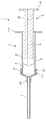
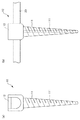
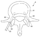
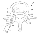
図1は、シリンジの実施形態を示す部分断面側面図、図2は、図1のシリンジに骨補填材を収納した状態を示す部分断面側面図、図3は、図2のシリンジにガイドワイヤを挿通した状態を示す部分断面側面図、図4は、図3のシリンジのプランジャを移動操作した状態を示す部分断面側面図、図5は、スクリューの構成を示す側面図、図6〜図12は、脊椎後方固定術を説明するための図である。なお、以下では、図1〜図4中の左側を「先端」または「先端側」と言い、右側を「基端」または「基端側」と言う。また、図6〜図11中の上側を「先端」または「先端側」と言い、下側を「基端」または「基端側」と言う。
<Processing set>
1 is a partial cross-sectional side view showing an embodiment of a syringe, FIG. 2 is a partial cross-sectional side view showing a state in which a bone filling material is stored in the syringe of FIG. 1, and FIG. 3 is a guide wire attached to the syringe of FIG. A partial cross-sectional side view showing the inserted state, FIG. 4 is a partial cross-sectional side view showing a state in which the plunger of the syringe of FIG. 3 is moved, FIG. 5 is a side view showing a screw configuration, and FIGS. , It is a figure for demonstrating posterior spinal fusion. In the following, the left side in FIGS. 1 to 4 is referred to as "tip" or "tip side", and the right side is referred to as "base end" or "base end side". Further, the upper side in FIGS. 6 to 11 is referred to as "tip" or "tip side", and the lower side is referred to as "base end" or "base end side".
本実施形態の処置セットは、脊椎後方固定術に使用される手術セットである。この処置セットは、シリンジ1と、シリンジ1とともに使用されるガイドワイヤ2(長尺部材)、スクリュー10(挿入具)およびロッド20とを有している。
The treatment set of this embodiment is a surgical set used for posterior spinal fusion. This treatment set includes a syringe 1 and a guide wire 2 (long member), screw 10 (insertor) and
<<シリンジ>>
シリンジ1は、図1に示すように、外筒3と、外筒3の先端部に設けられた細長い排出管4(排出口)と、外筒3内で液密に摺動するガスケット5と、ガスケット5に連結され、ガスケット5を外筒3内で移動操作するプランジャ6とを備えている。
<< Syringe >>
As shown in FIG. 1, the syringe 1 includes an
外筒3内には、ガスケット5により囲まれる内部空間が画成される。内部空間の容積は、特に限定されないが、好ましくは20mL以上300mL以下程度、より好ましくは50mL以上200mL以下程度とされる。この内部空間には、図2に示すように、ペースト状の骨補填材Fが収納される。この骨補填材Fとしては、例えば、セメント粉剤と硬化液との混合物が挙げられる。
An internal space surrounded by the gasket 5 is defined in the
セメント粉剤としては、例えば、α型第3リン酸カルシウム、第4リン酸カルシウム等を主成分とするセメントが挙げられる。具体的には、セメント粉剤としては、α型第3リン酸カルシウムまたは第4リン酸カルシウム単体およびこれらの混合物、α型第3リン酸カルシウムと第2リン酸カルシウムおよび/または第1リン酸カルシウムとの混合物、第4リン酸カルシウムと第2リン酸カルシウムおよび/または第1リン酸カルシウムとの混合物、α型第3リン酸カルシウムと第4リン酸カルシウムと第2リン酸カルシウムおよび/または第1リン酸カルシウム等の混合物等が好適に用いられる。
Examples of the cement powder include cement containing α-
一方、硬化液としては、例えば、水、ポリアクリル酸、クエン酸、リンゴ酸またはこれらの混合物のような有機酸を溶解した水溶液、塩化ナトリウム、コンドロイチン硫酸ナトリウム、コハク酸ナトリウム、乳酸ナトリウムまたはこれらの混合物のような水溶性塩類を溶解した水溶液等が好適に用いられる。 On the other hand, as the curing liquid, for example, an aqueous solution in which an organic acid such as water, polyacrylic acid, citric acid, malic acid or a mixture thereof is dissolved, sodium chloride, sodium chondroitin sulfate, sodium succinate, sodium lactate or a mixture thereof An aqueous solution in which water-soluble salts such as a mixture are dissolved is preferably used.
外筒3は、円筒状の本体31と、本体31の先端部に装着される蓋体32とで構成されている。本体31の先端部外周には、ネジ山311が形成され、蓋体32の基端側内周には、ネジ溝321が形成されている。したがって、本実施形態では、蓋体32は、螺合により本体31に装着される。なお、蓋体32は、嵌合により本体31に装着されるように構成されていてもよい。
The
また、外筒3(本体31)の基端外周には、板状のフランジ312が一体的に形成されている。プランジャ6を外筒3に対し相対的に移動操作する際等には、このフランジ312に指等を掛けて操作を行うことができる。
Further, a plate-shaped
蓋体32の先端中央部には、外筒3(蓋体32)の胴部より縮径し、先端方向に向かって突出する接続部322が一体的に形成されている。この接続部322の内側に排出管4の基端部が挿入、固定されている。排出管4の接続部322への固定方法は、特に限定されないが、例えば、カシメ、接着剤による接着、融着等が挙げられる。
At the center of the tip of the
外筒3およびプランジャ6の構成材料としては、それぞれ、例えば、ポリ塩化ビニル、ポリエチレン、ポリプロピレン、ポリスチレン、ポリ−(4−メチルペンテン−1)、ポリカーボネート、ポリエステル、ポリアミド、ポリエーテルスルホン、ポリスルホン、アクリル樹脂等が挙げられ、これらのうちの1種または2種以上を組み合わせて用いることができる。
The constituent materials of the
排出管4は、その基端部が蓋体32に固定され、先端部が骨補填材Fを補填すべき位置に導入され、この先端部から骨補填材を排出する。
The base end of the
排出管4の構成材料としては、例えば、ステンレス鋼、アルミニウムまたはアルミニウム合金、チタンまたはチタン合金等が挙げられる。また、外筒およびプランジャの構成材料として挙げた上記の樹脂であってもよい。
Examples of the constituent material of the
また、排出管4の長さは、特に限定されないが、好ましくは30mm以上140mm以下程度、より好ましくは60mm以上100mm以下程度である。
The length of the
さらに、後に詳述するが、排出管4は、ガイドワイヤ2を挿通した状態で、骨補填材Fをその先端部から排出する必要がある。そのため、ガイドワイヤ2の横断面積をZ[mm2]とし、排出管4の内腔部の横断面積をW[mm2]としたとき、W/Zが1.5以上200以下程度であることが好ましく、4以上100以下程度であることがより好ましい。W/Zを前記範囲とすることにより、ガイドワイヤ2を排出管4に挿通した状態としても、骨補填材Fを円滑に排出することができる。
Further, as will be described in detail later, the
排出管4の内腔部の横断面積の具体的な値は、特に限定されないが、3mm2以上200mm2以下程度であることが好ましく、10mm2以上100mm2以下程度がより好ましい。このようなサイズの排出管4であれば、一般的に使用されるガイドワイヤ2を無理なく挿通することができるとともに、骨補填材Fを円滑に排出することができる。
Specific values of the cross-sectional area of the lumen of the
外筒3内には、弾性材料で構成されたガスケット5が収納されている。このガスケット5は、プランジャ6の操作により、外筒3の軸方向(長手方向)に沿って摺動する。
A gasket 5 made of an elastic material is housed in the
ガスケット5の構成材料(弾性材料)としては、例えば、天然ゴム、ブチルゴム、イソプレンゴム、ブタジエンゴム、スチレン−ブタジエンゴムのようなゴム材料、熱可塑性エラストマー、またはこれらの混合物等が挙げられる。 Examples of the constituent material (elastic material) of the gasket 5 include rubber materials such as natural rubber, butyl rubber, isoprene rubber, butadiene rubber, and styrene-butadiene rubber, thermoplastic elastomers, and mixtures thereof.
なお、ガスケット5の外周には、被覆層が形成されていてよい。この被覆層の構成材料としては、例えば、ポリテトラフルオロエチレン、エチレン−テトラフルオロエチレン共重合体、四フッ化エチレンのようなフッ素系樹脂等が挙げられる。これにより、ガスケット5の外筒3に対する摺動性が向上する。
A coating layer may be formed on the outer periphery of the gasket 5. Examples of the constituent material of this coating layer include polytetrafluoroethylene, ethylene-tetrafluoroethylene copolymer, and a fluororesin such as tetrafluoroethylene. As a result, the slidability of the gasket 5 with respect to the
このようなガスケット5は、図示を省略するが、中空部を有しており、この中空部にプランジャ6のヘッド部が嵌合され、これにより、ガスケット5にプランジャ6が連結されている。 Although not shown, such a gasket 5 has a hollow portion, and the head portion of the plunger 6 is fitted into the hollow portion, whereby the plunger 6 is connected to the gasket 5.
プランジャ6は、長尺のプランジャ本体61と、このプランジャ本体61の基端外周に一体的に形成された板状のフランジ62とで構成されている。フランジ62に指等を掛けて、プランジャ6を操作することができる。
The plunger 6 is composed of a long plunger
このプランジャ6(プランジャ本体61)は、その軸方向に沿って形成された貫通孔60を備えている。本実施形態では、図3に示すように、シリンジ1は、貫通孔60および排出管4に、ガイドワイヤ2を挿通した状態で使用される。
The plunger 6 (plunger main body 61) includes a through
プランジャ本体61の横断面積をX[mm2]とし、貫通孔60の横断面積をY[mm2]としたとき、X/Yが3以上200以下程度であることが好ましく、4以上100以下程度であることがより好ましい。X/Yを前記範囲とすることにより、プランジャ本体61の機械的強度が低下するのを防止しつつ、ガイドワイヤ2を挿通するのに十分なサイズの貫通孔60を確保することができる。
When the cross-sectional area of the
ここで、「横断面」とは、部材または空間の軸方向(長手方向)に対して垂直な面または領域を言い、「横断面積」とは、かかる面または領域の大きさのことを言う。 Here, the "cross section" refers to a surface or region perpendicular to the axial direction (longitudinal direction) of the member or space, and the "cross-sectional area" refers to the size of such a surface or region.
また、貫通孔60の横断面積をY[mm2]とし、ガイドワイヤ2の横断面積をZ[mm2]としたとき、Y/Zが1.1以上200以下程度であることが好ましく、1.5以上100以下程度であることがより好ましい。Y/Zを前記範囲とすることにより、ガイドワイヤ2を円滑に貫通孔60に挿通することができる。
Further, when the cross-sectional area of the through
貫通孔60の横断面積の具体的な値は、特に限定されないが、2mm2以上200mm2以下程度であることが好ましく、10mm2以上120mm2以下程度であることがより好ましい。このようなサイズの貫通孔60であれば、一般的に使用されるガイドワイヤ2を無理なく挿通することができる。
The specific value of the cross-sectional area of the through
また、貫通孔60の横断面の形状は、特に限定されず、例えば、円形状、楕円形状、三角形状、四角形状、五角形状、六角形状のような多角形状、星形状のような異形状等のいかなる形状であってもよい。
The shape of the cross section of the through
本実施形態では、貫通孔60の中心軸は、排出管4の中心軸とほぼ一致しており、さらに排出管4の中心軸は、外筒3の中心軸とがほぼ一致している。かかる構成により、貫通孔60、排出管4および外筒3が同心的に配置されるため、ガイドワイヤ2を貫通孔60および排出管4により容易かつ迅速に挿通することができる。
In the present embodiment, the central axis of the through
このようなシリンジ1では、図3および図4に示すように、排出管4にガイドワイヤ2を挿通した状態で、プランジャ6を操作してガスケット5を先端方向に向かって移動させることにより、外筒3の内部空間の容積を減少させる。これにより、骨補填材Fを排出管4とガイドワイヤ2との間の空間を通過させ、排出管4の先端から排出させる。
In such a syringe 1, as shown in FIGS. 3 and 4, with the
このため、骨補填材Fは、十分な流動性(十分に低い粘度)を有することが好ましい。具体的には、骨補填材Fの粘度は、105mPa・s以上109mPa・s以下程度であることが好ましく、106mPa・s以上108mPa・s以下程度であることがより好ましい。かかる粘度を有する骨補填材Fであれば、排出管4とガイドワイヤ2との間の狭い空間を円滑に通過させることができる。
Therefore, the bone filling material F preferably has sufficient fluidity (sufficiently low viscosity). Specifically, the viscosity of the bone filling material F is preferably about 10 5 mPa · s or more and 10 9 mPa · s or less, and more preferably about 10 6 mPa · s or more and 10 8 mPa · s or less. preferable. The bone filling material F having such a viscosity can smoothly pass through a narrow space between the
また、排出管4および貫通孔60にガイドワイヤ2を挿通する際には、ガイドワイヤ2は、ガスケット5の先端中央部を刺通することになる。このため、ガスケット5の先端中央部には、ガイドワイヤ2が通過する孔を予め形成するようにしてもよいし、形成しなくてもよい。
Further, when the
前者の場合、形成する孔の横断面積は、ガイドワイヤ2の横断面積より小さく設定される。一方、後者の場合、ガイドワイヤ2がガスケット5を刺通することにより、ガスケット5の先端中央部に孔が形成される。
In the former case, the cross-sectional area of the hole to be formed is set to be smaller than the cross-sectional area of the
ガスケット5は、前述したように弾性材料で構成されるため、上記いずれの場合でも、刺通されたガイドワイヤ2の外面に密着して液密性が確保される。このため、図3に示す状態から、プランジャ6を操作してガスケット5を先端方向に向かって移動させても、骨補填材Fが貫通孔60に入り込む(逆流する)ことが阻止される。
Since the gasket 5 is made of an elastic material as described above, in any of the above cases, the gasket 5 is in close contact with the outer surface of the
<<スクリュー>>
以上のようなシリンジ1とともに、スクリュー10(挿入具)も使用される。このスクリュー10は、図5(a)に示すように、正面視においてU字状の頭部を備えるスクリュー本体11と、スクリュー本体11の頭部に螺合により装着されるロッキングキャップ12とを備えている。また、スクリュー本体11には、軸方向に沿って貫通孔111が形成されている。この貫通孔111の横断面積も、貫通孔60の横断面積と同様に設定することができる。
<< Screw >>
Along with the syringe 1 as described above, a screw 10 (inserting tool) is also used. As shown in FIG. 5A, the
このようなスクリュー10では、図5(b)に示すように、頭部の内側にロッド20を位置させ、ロッキングキャップ12を頭部に螺合させ、締め付けることにより、ロッド20をスクリュー10に固定することができる。
In such a
スクリュー10およびロッド20の構成材料としては、それぞれ、例えば、チタンまたはチタン合金、ステンレス鋼のような各種金属材料、ハイドロキシアパタイトのような各種バイオセラミックス等が挙げられる。
Examples of the constituent materials of the
<脊椎後方固定術>
次に、処置セットの使用方法の一例、すなわち処置セットを用いた脊椎後方固定術について説明する。
<Post-spine fusion>
Next, an example of how to use the treatment set, that is, posterior spinal fusion using the treatment set will be described.
[1] まず、セメント粉剤と硬化液と混合してペースト状の骨補填材Fを調製する。この操作は、セメント粉剤と硬化液と所定の乳鉢セットを用いて混練することにより行うことができる。これに代えて、この操作は、本体31から蓋体32を取り外し、本体31内にセメント粉剤を供給した後、硬化液を収納した別のシリンジと本体31とを接続し、この状態を維持しつつ、別のシリンジから硬化液を本体31内に供給して、本体31と別のシリンジ内で混合物を数回にわたって往復移動させることで混練することもできる。
[1] First, a paste-like bone filling material F is prepared by mixing a cement powder and a hardening liquid. This operation can be performed by kneading the cement powder, the curing liquid, and a predetermined mortar set. Instead of this, in this operation, the
[2] 次に、前者の場合、本体31から蓋体32を取り外し、本体31内に骨補填材Fを供給した後、本体31に蓋体32を螺合により装着する。後者の場合、本体31から別のシリンジを取り外した後、本体31に蓋体32を螺合により装着する。このようにして、図2に示すように、骨補填材Fを外筒3内に収納した状態のシリンジ1を準備する。
[2] Next, in the former case, the
[3] 次に、患者の背中の所定の位置をメスで切開して、処置すべき椎骨9を露出させる。その後、椎骨9の神経を圧迫している部位を取り除く。さらに、椎弓92が有する横突起および椎間関節の表面の一部を取り除く。これにより、骨補填材Fの椎骨9への付きが良好になり、また、椎弓92へのスクリュー10の取り付けを容易に行うことができる。
[3] Next, a predetermined position on the back of the patient is incised with a scalpel to expose the
[4] 次に、X線等の透視下で、椎弓92のスクリュー10を螺合すべき位置に、図6に示すように、椎体91に向けてプローベ30(処置具)を穿刺する。これにより、椎骨9の左右両側には、各椎弓92から椎体91に向けて、下穴93(欠損部)が形成される。なお、下穴93は、椎体91内の海綿骨に到達してもよいし、到達していなくてもよい。
[4] Next, the probe 30 (treatment tool) is punctured toward the
[5] 次に、図7に示すように、ガイドワイヤ2の先端部を下穴93に挿入する。その後、この状態を維持しつつ、ガイドワイヤ2を基端から、排出管4に挿通し、ガイドワイヤ2に沿ってシリンジ1を椎骨9に向けて前進させる。これにより、シリンジ1は、ガイドワイヤ2に案内されて、その排出管4の先端側が、図8に示すように、下穴93に挿入される。このとき、ガイドワイヤ2は、図3に示すように、ガスケット5を刺通した後、貫通孔60に挿通される。
[5] Next, as shown in FIG. 7, the tip end portion of the
[6] 次に、図4に示すように、プランジャ6を操作することによりガスケット5を先端方向に移動させ、骨補填材Fを排出管4の先端部から排出する。これにより、骨補填材Fを椎体91および下穴93に注入(充填)する。
[6] Next, as shown in FIG. 4, the gasket 5 is moved toward the tip by operating the plunger 6, and the bone filling material F is discharged from the tip of the
このとき、蓋体32が本体31に螺合しているため、プランジャ6に付与する押圧力(すなわち、外筒3内の骨補填材Fへ付与される圧力)が大きい場合でも、本体31から離脱し難い。このため、骨補填材Fを椎体91および下穴93に確実に注入することができる。その後、図9に示すように、ガイドワイヤ2を残して、シリンジ1を抜去する。
At this time, since the
[7] 次に、スクリュー本体11の貫通孔111に残されたガイドワイヤ2を挿通し、スクリュー本体11をガイドワイヤ2に沿って椎骨9に向けて前進させる。これにより、スクリュー本体11は、ガイドワイヤ2により案内されて、そのネジ部が下穴93に挿入される。その後、図示しない治具を用いて、スクリュー本体11を回転させることにより、図10に示すように、スクリュー本体11が椎骨9に固定される。
[7] Next, the
[8] 次に、スクリュー本体11を残して、図11に示すように、ガイドワイヤ2を抜去する。
[8] Next, the
以上の工程[3]〜[8]を、神経を圧迫している上下(複数)の椎骨9に対して実施する。
The above steps [3] to [8] are performed on the upper and lower (plural)
[9] 次に、図12に示すように、上下に位置する椎骨9の下穴93に固定されたスクリュー本体11に跨るようにして、ロッド20を配置する。その後、各スクリュー本体11の頭部にロッキングキャップ12を螺合により装着した後、締め付けることにより、ロッド20がスクリュー10に固定される。これにより、上下の椎骨9は、それらの離間距離が適切な大きさに保たれて固定される。その結果、神経の圧迫が除去された状態で、脊椎の安定性が確保される。
[9] Next, as shown in FIG. 12, the
[10] 次に、横突起および椎間関節の一部を取り除いた位置に、自家骨または人工骨を配置する。これにより、上下の椎骨9同士を、より強固に固定することができ、脊椎の安定性をより確実に確保することができる。なお、自家骨または人工骨の脊椎への配置を省略するようにしてもよい。
[10] Next, the autologous bone or the artificial bone is placed at a position where a part of the transverse process and the facet joint is removed. As a result, the upper and
そして、脊椎後方固定術が終了した後に、術部(切開部)に対し縫合、結紮等を行い、手術を終了する。 Then, after the posterior spinal fusion is completed, the surgical site (incision) is sutured, ligated, and the like, and the surgery is completed.
以上説明したような手技によれば、シリンジ1やスクリュー本体11を、ガイドワイヤ2に沿って椎骨9に向かって前進させるため、シリンジ1の排出管4やスクリュー本体11のネジ部を下穴93に迅速かつ確実に挿入することができる。その結果、骨補填材Fを椎体91および下穴93に注入(充填)することや、スクリュー本体11を椎骨9(椎弓92)に固定することをより容易に行うことができる。
According to the procedure described above, in order to advance the syringe 1 and the
また、骨補填材Fは、下穴93において椎骨9とスクリュー本体11のネジ部との間に介在して、スクリュー本体11の足場として機能する。これにより、スクリュー本体11は、十分な固定強度で椎骨9に固定される。
Further, the bone filling material F is interposed between the
さらに、このようなガイドワイヤ2とシリンジ1とスクリュー10とを用いた手技によれば、患者の背中の切開部分を極めて小さくすることもできる。このようなことから、患者への負担を軽減しつつ、確実かつ安全な手術(脊椎後方固定術)を行うことができる。
Further, according to the procedure using the
以上、本発明のシリンジおよび処置セットを図示の実施形態に基づいて説明したが、本発明は、これに限定されるものではない。例えば、本発明のシリンジおよび処置セットは、各部の構成を同様の機能を発揮し得る任意の構成と置換することができ、任意の構成を付加することもできる。 Although the syringe and treatment set of the present invention have been described above based on the illustrated embodiments, the present invention is not limited thereto. For example, in the syringe and treatment set of the present invention, the configuration of each part can be replaced with any configuration capable of exerting the same function, and any configuration can be added.
なお、本発明のシリンジおよび処置セットは、脊椎後方固定術のみならず、椎体、大腿骨のような長骨の骨欠損部の補修、整復を要する骨折部に対する補修や固定の補助、金属製の人工材料の骨に対する固定、人工関節と骨母床との間の間隙への骨補填材の充填等に使用することができる。本発明のシリンジは、特に、椎体圧迫骨折の手技に用いることが好適である。従来のシリンジは、ガイドワイヤで案内することができなかったので、視野確保のため椎体を大きく露出する必要があり、どうしても背中の切開部分が大きくなってしまっていた。しかし、本発明のシリンジは、ガイドワイヤに案内されて、椎体に接近させることができるので、切開部分は非常に小さくてすむ。 The syringe and treatment set of the present invention are not only for posterior spinal fusion, but also for repair of long bone defects such as vertebral bodies and femoral bones, repair and fixation assistance for fractures requiring reduction, and metal. It can be used for fixing the artificial material to the bone, filling the gap between the artificial joint and the bone mother bed with the bone filling material, and the like. The syringe of the present invention is particularly suitable for use in the procedure of vertebral compression fracture. Since the conventional syringe could not be guided by the guide wire, it was necessary to expose the vertebral body to a large extent in order to secure the visual field, and the incised part of the back was inevitably large. However, the syringe of the present invention can be guided by a guide wire to approach the vertebral body, so that the incision portion can be very small.
また、大腿骨の転子部骨折の手術においてはネイル等を用いる場合があるが、この場合、シリンジはネイル等を固定するための取付装置越しにガイドワイヤで案内するので、排出管は長いほうがよい。具体的に排出管の長さは、好ましくは100mm以上600mm以下程度、より好ましくは300mm以上450mm以下程度に設定される。 In addition, nails and the like may be used in surgery for trochanteric fractures of the femur. In this case, the syringe is guided by a guide wire through the attachment device for fixing the nails and the like, so the longer the discharge tube is, the better. good. Specifically, the length of the discharge pipe is preferably set to about 100 mm or more and 600 mm or less, and more preferably about 300 mm or more and 450 mm or less.
また、本発明のシリンジとともに用いられる長尺部材(本発明の処置セットが有する長尺部材)は、ガイドワイヤに限らず、例えば、カテーテルのような中空の部材であってもよい。さらに、本発明のシリンジとともに用いられる挿入具は、スクリューに限らず、例えば、骨栓のような栓体であってもよい。なお、本発明のシリンジは、単独で使用することもできる。 Further, the long member used together with the syringe of the present invention (the long member included in the treatment set of the present invention) is not limited to the guide wire, and may be a hollow member such as a catheter, for example. Further, the insertion tool used together with the syringe of the present invention is not limited to the screw, and may be a plug such as a bone plug. The syringe of the present invention can also be used alone.
さらに、本発明のシリンジおよび処置セットを使用可能な物体は、骨に限らず、例えば、電子部品、建築部品等であってもよい。特に、生体、電子機器や建築物の内部に位置し、これらの外部から目視で確認し難い物体の欠損部に流体(例えば、接着剤、封止材、洗浄液等)を注入するのに、本発明のシリンジおよび処置セットが好適に使用される。 Furthermore, the object to which the syringe and treatment set of the present invention can be used is not limited to bone, and may be, for example, electronic parts, building parts, and the like. In particular, this book is used to inject fluid (for example, adhesives, encapsulants, cleaning liquids, etc.) into defective parts of objects that are located inside living organisms, electronic devices, and buildings and are difficult to visually confirm from the outside. The syringe and treatment set of the invention are preferably used.
また、本発明のシリンジおよび処置セットにおいて使用可能な流体は、ペースト状(ゲル状)の形態に限らず、例えば、液状、顆粒状、粉末状等の形態であってもよい。 Further, the fluid that can be used in the syringe and treatment set of the present invention is not limited to a paste-like (gel-like) form, and may be, for example, a liquid, granular, or powder-like form.
1 シリンジ
2 ガイドワイヤ
3 外筒
31 本体
311 ネジ山
312 フランジ
32 蓋体
321 ネジ溝
322 接続部
4 排出管
5 ガスケット
6 プランジャ
60 貫通孔
61 プランジャ本体
62 フランジ
9 椎骨
91 椎体
92 椎弓
93 下穴
10 スクリュー
11 スクリュー本体
111 貫通孔
12 ロッキングキャップ
20 ロッド
30 プローベ
F 骨補填材
1
Claims (3)
前記外筒の先端部から突出し、前記流体を排出する排出口と、
前記外筒内に摺動可能に設けられたガスケットと、
軸方向に沿って形成された貫通孔を備え、前記ガスケットを前記外筒内で移動操作するプランジャとを有し、
前記外筒は、略一定の直径を有する筒状の本体と、前記排出口が接着又は融着により接続された接続部を有し、該本体の先端部に螺合により装着された蓋体とを備え、
前記蓋体の接続部は、前記外筒の筒状の本体よりも小さい直径を有するシリンジであって、
前記シリンジは、前記貫通孔および前記排出口に、長尺部材を挿通した状態で流体を注入するのに使用され、前記長尺部材は、ガイドワイヤであり、
脊椎後方固定術に使用されることを特徴とするシリンジ。 An outer cylinder that can store fluid and
A discharge port that protrudes from the tip of the outer cylinder and discharges the fluid,
A gasket provided so as to be slidable in the outer cylinder, and
It has a through hole formed along the axial direction, and has a plunger for moving and operating the gasket in the outer cylinder.
The outer cylinder has a tubular main body having a substantially constant diameter and a connecting portion in which the discharge port is connected by adhesion or fusion, and a lid body screwed onto the tip of the main body. With
Connecting portion of the lid is a syringe that have a smaller diameter than the tubular body of the outer cylinder,
The syringe is used to inject a fluid with a long member inserted into the through hole and the discharge port, and the long member is a guide wire.
A syringe characterized by being used for posterior spinal fusion.
前記排出口の中心軸と前記外筒の中心軸とがほぼ一致し、
前記プランジャは、長尺のプランジャ本体を備え、
前記プランジャ本体の横断面積をX[mm 2 ]とし、前記貫通孔の横断面積をY[mm 2 ]としたとき、X/Yが3以上200以下であり、
前記蓋体と前記接続部とは一体的に形成されており、
前記接続部の内側に前記排出口の基端部が固定され、
前記長尺部材を前記貫通孔および前記排出口に挿通した際に、前記ガスケットは、前記長尺部材により刺通された状態となり、この状態で前記長尺部材の外面に密着し、
前記貫通孔の横断面積をY[mm 2 ]とし、前記長尺部材の横断面積をZ[mm 2 ]としたとき、Y/Zが1.1以上200以下である請求項6または7に記載のシリンジ。
前記長尺部材の横断面積をZ[mm 2 ]とし、前記排出口の内腔部の横断面積をW[mm 2 ]としたとき、W/Zが1.5以上200以下である請求項1に記載のシリンジ。 The central axis of the through hole and the central axis of the outlet are substantially aligned with each other.
The central axis of the discharge port and the central axis of the outer cylinder substantially coincide with each other.
The plunger is provided with a long plunger body.
When the cross-sectional area of the plunger body is X [mm 2 ] and the cross-sectional area of the through hole is Y [mm 2 ], X / Y is 3 or more and 200 or less.
The lid body and the connection portion are integrally formed, and the lid body and the connection portion are integrally formed.
The base end of the outlet is fixed inside the connection,
When the long member is inserted into the through hole and the discharge port, the gasket is in a state of being pierced by the long member, and in this state, the gasket is brought into close contact with the outer surface of the long member.
The cross-sectional area of the through hole and Y [mm 2], the length when the cross-sectional area of the elongated member and a Z [mm 2], according to claim 6 or 7 Y / Z is 200 or less than 1.1 Syringe.
Claim 1 in which W / Z is 1.5 or more and 200 or less when the cross-sectional area of the long member is Z [mm 2 ] and the cross-sectional area of the lumen of the discharge port is W [mm 2]. The syringe described in.
請求項1又は2に記載のシリンジと、
前記貫通孔および前記排出口に挿通され、前記シリンジの前記排出口を前記欠損部またはその近傍に案内するガイドワイヤとを有し、
前記処置セットは、さらに、前記欠損部に挿入される挿入具を有し、
前記挿入具は、該挿入具の軸方向に沿って貫通孔が形成されたスクリュー本体を備えたスクリューであり、
前記スクリュー本体は、ガイドワイヤを挿通可能な貫通孔を備え、
前記流体は、その粘度が10 5 mPa・s以上10 9 mPa・s以下であることを特徴とする処置セット。 A set of procedures used to inject fluid into a defect in an object in posterior spinal fusion.
The syringe according to claim 1 or 2,
Wherein is inserted into the through hole and the discharge port, the discharge port of the syringe have a guide wire to guide the defect or near,
The treatment set further comprises an inserter that is inserted into the defect.
The inserter is a screw having a screw body having a through hole formed along the axial direction of the inserter.
The screw body has a through hole through which a guide wire can be inserted.
The fluid treatment set, characterized in that its viscosity is less than 10 5 mPa · s or more 10 9 mPa · s.
Priority Applications (1)
| Application Number | Priority Date | Filing Date | Title |
|---|---|---|---|
| JP2016251619A JP6936005B2 (en) | 2016-12-26 | 2016-12-26 | Syringe and treatment set |
Applications Claiming Priority (1)
| Application Number | Priority Date | Filing Date | Title |
|---|---|---|---|
| JP2016251619A JP6936005B2 (en) | 2016-12-26 | 2016-12-26 | Syringe and treatment set |
Publications (2)
| Publication Number | Publication Date |
|---|---|
| JP2018102551A JP2018102551A (en) | 2018-07-05 |
| JP6936005B2 true JP6936005B2 (en) | 2021-09-15 |
Family
ID=62785848
Family Applications (1)
| Application Number | Title | Priority Date | Filing Date |
|---|---|---|---|
| JP2016251619A Active JP6936005B2 (en) | 2016-12-26 | 2016-12-26 | Syringe and treatment set |
Country Status (1)
| Country | Link |
|---|---|
| JP (1) | JP6936005B2 (en) |
Family Cites Families (6)
| Publication number | Priority date | Publication date | Assignee | Title |
|---|---|---|---|---|
| JPS54104687U (en) * | 1977-12-29 | 1979-07-23 | ||
| US6409972B1 (en) * | 1995-06-06 | 2002-06-25 | Kwan-Ho Chan | Prepackaged liquid bone cement |
| WO2001047571A2 (en) * | 1999-12-29 | 2001-07-05 | Regeneration Technologies, Inc. | System for reconstituting pastes and methods of using same |
| US8613744B2 (en) * | 2002-09-30 | 2013-12-24 | Relievant Medsystems, Inc. | Systems and methods for navigating an instrument through bone |
| US20060253081A1 (en) * | 2005-04-25 | 2006-11-09 | Paulos Lonnie E | Cannulated injection system |
| US7976506B2 (en) * | 2006-09-29 | 2011-07-12 | Arrow International, Inc. | Syringe with selectable indicia of contents |
-
2016
- 2016-12-26 JP JP2016251619A patent/JP6936005B2/en active Active
Also Published As
| Publication number | Publication date |
|---|---|
| JP2018102551A (en) | 2018-07-05 |
Similar Documents
| Publication | Publication Date | Title |
|---|---|---|
| US11794157B2 (en) | Bone cement mixing and delivery system with reduced fume exposure | |
| US20100030135A1 (en) | Method and apparatus for anchoring bone screws and injecting many types of high viscosity materials in areas surrounding bone | |
| JP4709892B2 (en) | Bone implant adhesion enhancer | |
| US7575572B2 (en) | Method and device for delivering medicine to bone | |
| US7608062B2 (en) | Method and device for delivering medicine to bone | |
| US8808337B2 (en) | Method and device for delivering medicine to bone | |
| CA2831057C (en) | Cannula and kit for evaluation and preparation of bone tissue | |
| US20090198243A1 (en) | Device and method for stabilizing a damaged bone with a bone cement mixture | |
| US20090149860A1 (en) | Device for delivery of bone void filling materials | |
| US20040249347A1 (en) | High pressure delivery system | |
| JP2009540938A (en) | System and method for strengthening spinous processes | |
| JP2007511324A (en) | Windowed bone tap and method | |
| AU2009239515A1 (en) | Posterior spinal fastener | |
| JP6936005B2 (en) | Syringe and treatment set | |
| AU2015277489B2 (en) | High pressure remote delivery system for cement and methods of use | |
| US11576710B2 (en) | Dispensing system and method | |
| CA2438786A1 (en) | Biocompatible material | |
| AU2002236973A1 (en) | Delivery of Biocompatible Material |
Legal Events
| Date | Code | Title | Description |
|---|---|---|---|
| A621 | Written request for application examination |
Free format text: JAPANESE INTERMEDIATE CODE: A621 Effective date: 20190717 |
|
| A977 | Report on retrieval |
Free format text: JAPANESE INTERMEDIATE CODE: A971007 Effective date: 20200529 |
|
| A131 | Notification of reasons for refusal |
Free format text: JAPANESE INTERMEDIATE CODE: A131 Effective date: 20200609 |
|
| A521 | Written amendment |
Free format text: JAPANESE INTERMEDIATE CODE: A523 Effective date: 20200706 |
|
| RD05 | Notification of revocation of power of attorney |
Free format text: JAPANESE INTERMEDIATE CODE: A7425 Effective date: 20200706 |
|
| RD02 | Notification of acceptance of power of attorney |
Free format text: JAPANESE INTERMEDIATE CODE: A7422 Effective date: 20201005 |
|
| A521 | Written amendment |
Free format text: JAPANESE INTERMEDIATE CODE: A523 Effective date: 20201105 |
|
| A02 | Decision of refusal |
Free format text: JAPANESE INTERMEDIATE CODE: A02 Effective date: 20210406 |
|
| A521 | Written amendment |
Free format text: JAPANESE INTERMEDIATE CODE: A523 Effective date: 20210512 |
|
| C60 | Trial request (containing other claim documents, opposition documents) |
Free format text: JAPANESE INTERMEDIATE CODE: C60 Effective date: 20210512 |
|
| A911 | Transfer to examiner for re-examination before appeal (zenchi) |
Free format text: JAPANESE INTERMEDIATE CODE: A911 Effective date: 20210521 |
|
| C21 | Notice of transfer of a case for reconsideration by examiners before appeal proceedings |
Free format text: JAPANESE INTERMEDIATE CODE: C21 Effective date: 20210610 |
|
| TRDD | Decision of grant or rejection written | ||
| A01 | Written decision to grant a patent or to grant a registration (utility model) |
Free format text: JAPANESE INTERMEDIATE CODE: A01 Effective date: 20210824 |
|
| A61 | First payment of annual fees (during grant procedure) |
Free format text: JAPANESE INTERMEDIATE CODE: A61 Effective date: 20210826 |
|
| R150 | Certificate of patent or registration of utility model |
Ref document number: 6936005 Country of ref document: JP Free format text: JAPANESE INTERMEDIATE CODE: R150 |