JP6929773B2 - A fluid system with a culture channel containing a fluid system formed by molding - Google Patents
A fluid system with a culture channel containing a fluid system formed by molding Download PDFInfo
- Publication number
- JP6929773B2 JP6929773B2 JP2017531235A JP2017531235A JP6929773B2 JP 6929773 B2 JP6929773 B2 JP 6929773B2 JP 2017531235 A JP2017531235 A JP 2017531235A JP 2017531235 A JP2017531235 A JP 2017531235A JP 6929773 B2 JP6929773 B2 JP 6929773B2
- Authority
- JP
- Japan
- Prior art keywords
- sample
- channel
- culture
- fluid
- less
- Prior art date
- Legal status (The legal status is an assumption and is not a legal conclusion. Google has not performed a legal analysis and makes no representation as to the accuracy of the status listed.)
- Active
Links
- 239000012530 fluid Substances 0.000 title claims description 569
- 238000000465 moulding Methods 0.000 title description 2
- 238000001514 detection method Methods 0.000 claims description 257
- 239000003153 chemical reaction reagent Substances 0.000 claims description 204
- 238000000034 method Methods 0.000 claims description 98
- 238000002156 mixing Methods 0.000 claims description 71
- 239000007788 liquid Substances 0.000 claims description 57
- 238000004891 communication Methods 0.000 claims description 20
- 238000000151 deposition Methods 0.000 claims description 4
- 239000000523 sample Substances 0.000 description 378
- MUMGGOZAMZWBJJ-DYKIIFRCSA-N Testostosterone Chemical compound O=C1CC[C@]2(C)[C@H]3CC[C@](C)([C@H](CC4)O)[C@@H]4[C@@H]3CCC2=C1 MUMGGOZAMZWBJJ-DYKIIFRCSA-N 0.000 description 229
- 229960003604 testosterone Drugs 0.000 description 132
- 238000003556 assay Methods 0.000 description 102
- 239000000463 material Substances 0.000 description 71
- 238000006243 chemical reaction Methods 0.000 description 47
- 239000012491 analyte Substances 0.000 description 40
- 238000009739 binding Methods 0.000 description 37
- 230000027455 binding Effects 0.000 description 35
- 238000004458 analytical method Methods 0.000 description 32
- -1 pH adjusters Substances 0.000 description 32
- 239000000758 substrate Substances 0.000 description 29
- 230000003287 optical effect Effects 0.000 description 28
- 239000000126 substance Substances 0.000 description 28
- 229920000642 polymer Polymers 0.000 description 26
- 210000004369 blood Anatomy 0.000 description 24
- 239000008280 blood Substances 0.000 description 24
- 238000005259 measurement Methods 0.000 description 22
- 239000000203 mixture Substances 0.000 description 22
- BQCADISMDOOEFD-UHFFFAOYSA-N Silver Chemical compound [Ag] BQCADISMDOOEFD-UHFFFAOYSA-N 0.000 description 20
- 102000004169 proteins and genes Human genes 0.000 description 20
- 108090000623 proteins and genes Proteins 0.000 description 20
- 229910052709 silver Inorganic materials 0.000 description 20
- 239000004332 silver Substances 0.000 description 20
- 230000003321 amplification Effects 0.000 description 19
- 238000004519 manufacturing process Methods 0.000 description 19
- 229910052751 metal Inorganic materials 0.000 description 19
- 239000002184 metal Substances 0.000 description 19
- 238000003199 nucleic acid amplification method Methods 0.000 description 19
- 230000002829 reductive effect Effects 0.000 description 16
- 229920001577 copolymer Polymers 0.000 description 15
- 238000012258 culturing Methods 0.000 description 15
- 238000003860 storage Methods 0.000 description 13
- 238000012360 testing method Methods 0.000 description 13
- 238000002834 transmittance Methods 0.000 description 13
- 238000011144 upstream manufacturing Methods 0.000 description 13
- XLYOFNOQVPJJNP-UHFFFAOYSA-N water Chemical compound O XLYOFNOQVPJJNP-UHFFFAOYSA-N 0.000 description 12
- 230000005540 biological transmission Effects 0.000 description 11
- 239000000427 antigen Substances 0.000 description 10
- 239000003795 chemical substances by application Substances 0.000 description 10
- 230000035699 permeability Effects 0.000 description 10
- 239000000243 solution Substances 0.000 description 10
- 239000000080 wetting agent Substances 0.000 description 10
- 108091003079 Bovine Serum Albumin Proteins 0.000 description 9
- 108010089417 Sex Hormone-Binding Globulin Proteins 0.000 description 9
- 102100030758 Sex hormone-binding globulin Human genes 0.000 description 9
- 229940098773 bovine serum albumin Drugs 0.000 description 9
- 239000007789 gas Substances 0.000 description 9
- 230000009477 glass transition Effects 0.000 description 9
- PCHJSUWPFVWCPO-UHFFFAOYSA-N gold Chemical compound [Au] PCHJSUWPFVWCPO-UHFFFAOYSA-N 0.000 description 9
- 230000035945 sensitivity Effects 0.000 description 9
- 239000002699 waste material Substances 0.000 description 9
- PPBRXRYQALVLMV-UHFFFAOYSA-N Styrene Chemical compound C=CC1=CC=CC=C1 PPBRXRYQALVLMV-UHFFFAOYSA-N 0.000 description 8
- 102000036639 antigens Human genes 0.000 description 8
- 108091007433 antigens Proteins 0.000 description 8
- 239000000872 buffer Substances 0.000 description 8
- 229910052799 carbon Inorganic materials 0.000 description 8
- 238000001035 drying Methods 0.000 description 8
- 229910052737 gold Inorganic materials 0.000 description 8
- 239000010931 gold Substances 0.000 description 8
- 238000001746 injection moulding Methods 0.000 description 8
- 239000002245 particle Substances 0.000 description 8
- 150000003384 small molecules Chemical class 0.000 description 8
- 239000004094 surface-active agent Substances 0.000 description 8
- 108010072866 Prostate-Specific Antigen Proteins 0.000 description 7
- 102000007066 Prostate-Specific Antigen Human genes 0.000 description 7
- 238000012875 competitive assay Methods 0.000 description 7
- 230000000875 corresponding effect Effects 0.000 description 7
- 231100000673 dose–response relationship Toxicity 0.000 description 7
- 230000007246 mechanism Effects 0.000 description 7
- 230000008569 process Effects 0.000 description 7
- 230000003746 surface roughness Effects 0.000 description 7
- IJGRMHOSHXDMSA-UHFFFAOYSA-N Atomic nitrogen Chemical compound N#N IJGRMHOSHXDMSA-UHFFFAOYSA-N 0.000 description 6
- KAKZBPTYRLMSJV-UHFFFAOYSA-N Butadiene Chemical compound C=CC=C KAKZBPTYRLMSJV-UHFFFAOYSA-N 0.000 description 6
- 102000014914 Carrier Proteins Human genes 0.000 description 6
- 239000003146 anticoagulant agent Substances 0.000 description 6
- 229940127219 anticoagulant drug Drugs 0.000 description 6
- 239000002981 blocking agent Substances 0.000 description 6
- 239000003638 chemical reducing agent Substances 0.000 description 6
- 238000004108 freeze drying Methods 0.000 description 6
- 230000006870 function Effects 0.000 description 6
- 238000002372 labelling Methods 0.000 description 6
- 230000008018 melting Effects 0.000 description 6
- 238000002844 melting Methods 0.000 description 6
- KCXVZYZYPLLWCC-UHFFFAOYSA-N EDTA Chemical compound OC(=O)CN(CC(O)=O)CCN(CC(O)=O)CC(O)=O KCXVZYZYPLLWCC-UHFFFAOYSA-N 0.000 description 5
- 239000000853 adhesive Substances 0.000 description 5
- 230000001070 adhesive effect Effects 0.000 description 5
- 230000002411 adverse Effects 0.000 description 5
- 238000010494 dissociation reaction Methods 0.000 description 5
- 230000005593 dissociations Effects 0.000 description 5
- 229940088597 hormone Drugs 0.000 description 5
- 239000005556 hormone Substances 0.000 description 5
- 230000003993 interaction Effects 0.000 description 5
- 150000002739 metals Chemical class 0.000 description 5
- 239000013610 patient sample Substances 0.000 description 5
- 239000007790 solid phase Substances 0.000 description 5
- 230000007704 transition Effects 0.000 description 5
- PLIKAWJENQZMHA-UHFFFAOYSA-N 4-aminophenol Chemical compound NC1=CC=C(O)C=C1 PLIKAWJENQZMHA-UHFFFAOYSA-N 0.000 description 4
- QIGBRXMKCJKVMJ-UHFFFAOYSA-N Hydroquinone Chemical compound OC1=CC=C(O)C=C1 QIGBRXMKCJKVMJ-UHFFFAOYSA-N 0.000 description 4
- PXHVJJICTQNCMI-UHFFFAOYSA-N Nickel Chemical compound [Ni] PXHVJJICTQNCMI-UHFFFAOYSA-N 0.000 description 4
- RJKFOVLPORLFTN-LEKSSAKUSA-N Progesterone Chemical compound C1CC2=CC(=O)CC[C@]2(C)[C@@H]2[C@@H]1[C@@H]1CC[C@H](C(=O)C)[C@@]1(C)CC2 RJKFOVLPORLFTN-LEKSSAKUSA-N 0.000 description 4
- 230000009471 action Effects 0.000 description 4
- 239000007864 aqueous solution Substances 0.000 description 4
- 108091008324 binding proteins Proteins 0.000 description 4
- 230000000903 blocking effect Effects 0.000 description 4
- 239000000084 colloidal system Substances 0.000 description 4
- 238000013461 design Methods 0.000 description 4
- 238000009792 diffusion process Methods 0.000 description 4
- 239000003085 diluting agent Substances 0.000 description 4
- 238000011010 flushing procedure Methods 0.000 description 4
- 230000001900 immune effect Effects 0.000 description 4
- 230000000670 limiting effect Effects 0.000 description 4
- 102000039446 nucleic acids Human genes 0.000 description 4
- 108020004707 nucleic acids Proteins 0.000 description 4
- 150000007523 nucleic acids Chemical class 0.000 description 4
- 239000002243 precursor Substances 0.000 description 4
- WQGWDDDVZFFDIG-UHFFFAOYSA-N pyrogallol Chemical compound OC1=CC=CC(O)=C1O WQGWDDDVZFFDIG-UHFFFAOYSA-N 0.000 description 4
- 230000009467 reduction Effects 0.000 description 4
- SQGYOTSLMSWVJD-UHFFFAOYSA-N silver(1+) nitrate Chemical compound [Ag+].[O-]N(=O)=O SQGYOTSLMSWVJD-UHFFFAOYSA-N 0.000 description 4
- 239000002904 solvent Substances 0.000 description 4
- OOIBFPKQHULHSQ-UHFFFAOYSA-N (3-hydroxy-1-adamantyl) 2-methylprop-2-enoate Chemical compound C1C(C2)CC3CC2(O)CC1(OC(=O)C(=C)C)C3 OOIBFPKQHULHSQ-UHFFFAOYSA-N 0.000 description 3
- SORISAYAZBCIQH-XSSYPUMDSA-N (8r,9s,13s,14s,17s)-2-bromo-13-methyl-6,7,8,9,11,12,14,15,16,17-decahydrocyclopenta[a]phenanthrene-3,17-diol Chemical compound OC1=C(Br)C=C2[C@H]3CC[C@](C)([C@H](CC4)O)[C@@H]4[C@@H]3CCC2=C1 SORISAYAZBCIQH-XSSYPUMDSA-N 0.000 description 3
- NLHHRLWOUZZQLW-UHFFFAOYSA-N Acrylonitrile Chemical compound C=CC#N NLHHRLWOUZZQLW-UHFFFAOYSA-N 0.000 description 3
- 108091023037 Aptamer Proteins 0.000 description 3
- 102000004190 Enzymes Human genes 0.000 description 3
- 108090000790 Enzymes Proteins 0.000 description 3
- HTTJABKRGRZYRN-UHFFFAOYSA-N Heparin Chemical compound OC1C(NC(=O)C)C(O)OC(COS(O)(=O)=O)C1OC1C(OS(O)(=O)=O)C(O)C(OC2C(C(OS(O)(=O)=O)C(OC3C(C(O)C(O)C(O3)C(O)=O)OS(O)(=O)=O)C(CO)O2)NS(O)(=O)=O)C(C(O)=O)O1 HTTJABKRGRZYRN-UHFFFAOYSA-N 0.000 description 3
- LRHPLDYGYMQRHN-UHFFFAOYSA-N N-Butanol Chemical compound CCCCO LRHPLDYGYMQRHN-UHFFFAOYSA-N 0.000 description 3
- 239000004793 Polystyrene Substances 0.000 description 3
- 241000700605 Viruses Species 0.000 description 3
- 230000008901 benefit Effects 0.000 description 3
- 230000015572 biosynthetic process Effects 0.000 description 3
- 150000001720 carbohydrates Chemical class 0.000 description 3
- 235000014633 carbohydrates Nutrition 0.000 description 3
- 210000004027 cell Anatomy 0.000 description 3
- 230000008859 change Effects 0.000 description 3
- 238000004140 cleaning Methods 0.000 description 3
- 239000002131 composite material Substances 0.000 description 3
- 230000002596 correlated effect Effects 0.000 description 3
- IZEKFCXSFNUWAM-UHFFFAOYSA-N dipyridamole Chemical compound C=12N=C(N(CCO)CCO)N=C(N3CCCCC3)C2=NC(N(CCO)CCO)=NC=1N1CCCCC1 IZEKFCXSFNUWAM-UHFFFAOYSA-N 0.000 description 3
- 229960002768 dipyridamole Drugs 0.000 description 3
- 229940079593 drug Drugs 0.000 description 3
- 239000003814 drug Substances 0.000 description 3
- 239000000975 dye Substances 0.000 description 3
- 238000002474 experimental method Methods 0.000 description 3
- 238000011049 filling Methods 0.000 description 3
- 150000004676 glycans Chemical class 0.000 description 3
- 229920000669 heparin Polymers 0.000 description 3
- 229960002897 heparin Drugs 0.000 description 3
- 230000002209 hydrophobic effect Effects 0.000 description 3
- 238000005304 joining Methods 0.000 description 3
- 239000013642 negative control Substances 0.000 description 3
- 229910052757 nitrogen Inorganic materials 0.000 description 3
- 210000002381 plasma Anatomy 0.000 description 3
- 229920001282 polysaccharide Polymers 0.000 description 3
- 239000005017 polysaccharide Substances 0.000 description 3
- 229920002223 polystyrene Polymers 0.000 description 3
- 239000013641 positive control Substances 0.000 description 3
- 238000002360 preparation method Methods 0.000 description 3
- VYPSYNLAJGMNEJ-UHFFFAOYSA-N silicon dioxide Inorganic materials O=[Si]=O VYPSYNLAJGMNEJ-UHFFFAOYSA-N 0.000 description 3
- 241000894007 species Species 0.000 description 3
- 230000003068 static effect Effects 0.000 description 3
- 238000012546 transfer Methods 0.000 description 3
- VOXZDWNPVJITMN-ZBRFXRBCSA-N 17β-estradiol Chemical compound OC1=CC=C2[C@H]3CC[C@](C)([C@H](CC4)O)[C@@H]4[C@@H]3CCC2=C1 VOXZDWNPVJITMN-ZBRFXRBCSA-N 0.000 description 2
- ZVNPWFOVUDMGRP-UHFFFAOYSA-N 4-methylaminophenol sulfate Chemical compound OS(O)(=O)=O.CNC1=CC=C(O)C=C1.CNC1=CC=C(O)C=C1 ZVNPWFOVUDMGRP-UHFFFAOYSA-N 0.000 description 2
- 108010078791 Carrier Proteins Proteins 0.000 description 2
- RYGMFSIKBFXOCR-UHFFFAOYSA-N Copper Chemical compound [Cu] RYGMFSIKBFXOCR-UHFFFAOYSA-N 0.000 description 2
- 229920000089 Cyclic olefin copolymer Polymers 0.000 description 2
- 102000012673 Follicle Stimulating Hormone Human genes 0.000 description 2
- 108010079345 Follicle Stimulating Hormone Proteins 0.000 description 2
- KFZMGEQAYNKOFK-UHFFFAOYSA-N Isopropanol Chemical compound CC(C)O KFZMGEQAYNKOFK-UHFFFAOYSA-N 0.000 description 2
- 102000009151 Luteinizing Hormone Human genes 0.000 description 2
- 108010073521 Luteinizing Hormone Proteins 0.000 description 2
- 241001465754 Metazoa Species 0.000 description 2
- KDLHZDBZIXYQEI-UHFFFAOYSA-N Palladium Chemical compound [Pd] KDLHZDBZIXYQEI-UHFFFAOYSA-N 0.000 description 2
- 239000004698 Polyethylene Substances 0.000 description 2
- 239000004743 Polypropylene Substances 0.000 description 2
- DBMJMQXJHONAFJ-UHFFFAOYSA-M Sodium laurylsulphate Chemical compound [Na+].CCCCCCCCCCCCOS([O-])(=O)=O DBMJMQXJHONAFJ-UHFFFAOYSA-M 0.000 description 2
- 102000011923 Thyrotropin Human genes 0.000 description 2
- 108010061174 Thyrotropin Proteins 0.000 description 2
- MCMNRKCIXSYSNV-UHFFFAOYSA-N Zirconium dioxide Chemical compound O=[Zr]=O MCMNRKCIXSYSNV-UHFFFAOYSA-N 0.000 description 2
- 229910052782 aluminium Inorganic materials 0.000 description 2
- XAGFODPZIPBFFR-UHFFFAOYSA-N aluminium Chemical compound [Al] XAGFODPZIPBFFR-UHFFFAOYSA-N 0.000 description 2
- 150000001412 amines Chemical class 0.000 description 2
- 238000002820 assay format Methods 0.000 description 2
- 230000004888 barrier function Effects 0.000 description 2
- 238000005219 brazing Methods 0.000 description 2
- 230000015556 catabolic process Effects 0.000 description 2
- 239000000919 ceramic Substances 0.000 description 2
- AJPXTSMULZANCB-UHFFFAOYSA-N chlorohydroquinone Chemical compound OC1=CC=C(O)C(Cl)=C1 AJPXTSMULZANCB-UHFFFAOYSA-N 0.000 description 2
- 238000002967 competitive immunoassay Methods 0.000 description 2
- 230000000295 complement effect Effects 0.000 description 2
- 230000003750 conditioning effect Effects 0.000 description 2
- 239000004020 conductor Substances 0.000 description 2
- 230000001276 controlling effect Effects 0.000 description 2
- 229910052802 copper Inorganic materials 0.000 description 2
- 239000010949 copper Substances 0.000 description 2
- 238000006731 degradation reaction Methods 0.000 description 2
- 230000008021 deposition Effects 0.000 description 2
- 239000003599 detergent Substances 0.000 description 2
- 238000011038 discontinuous diafiltration by volume reduction Methods 0.000 description 2
- 230000000694 effects Effects 0.000 description 2
- 230000007613 environmental effect Effects 0.000 description 2
- 229960005309 estradiol Drugs 0.000 description 2
- 229930182833 estradiol Natural products 0.000 description 2
- 230000005284 excitation Effects 0.000 description 2
- OVBPIULPVIDEAO-LBPRGKRZSA-N folic acid Chemical compound C=1N=C2NC(N)=NC(=O)C2=NC=1CNC1=CC=C(C(=O)N[C@@H](CCC(O)=O)C(O)=O)C=C1 OVBPIULPVIDEAO-LBPRGKRZSA-N 0.000 description 2
- 229940028334 follicle stimulating hormone Drugs 0.000 description 2
- 125000000524 functional group Chemical group 0.000 description 2
- 239000011521 glass Substances 0.000 description 2
- 239000003292 glue Substances 0.000 description 2
- 238000010438 heat treatment Methods 0.000 description 2
- JYGXADMDTFJGBT-VWUMJDOOSA-N hydrocortisone Chemical compound O=C1CC[C@]2(C)[C@H]3[C@@H](O)C[C@](C)([C@@](CC4)(O)C(=O)CO)[C@@H]4[C@@H]3CCC2=C1 JYGXADMDTFJGBT-VWUMJDOOSA-N 0.000 description 2
- 230000006872 improvement Effects 0.000 description 2
- 239000003112 inhibitor Substances 0.000 description 2
- 239000003446 ligand Substances 0.000 description 2
- 230000031700 light absorption Effects 0.000 description 2
- 238000011068 loading method Methods 0.000 description 2
- 230000007774 longterm Effects 0.000 description 2
- 238000004020 luminiscence type Methods 0.000 description 2
- 229940040129 luteinizing hormone Drugs 0.000 description 2
- 239000002923 metal particle Substances 0.000 description 2
- 238000012986 modification Methods 0.000 description 2
- 230000004048 modification Effects 0.000 description 2
- 229910052759 nickel Inorganic materials 0.000 description 2
- CMCWWLVWPDLCRM-UHFFFAOYSA-N phenidone Chemical compound N1C(=O)CCN1C1=CC=CC=C1 CMCWWLVWPDLCRM-UHFFFAOYSA-N 0.000 description 2
- BASFCYQUMIYNBI-UHFFFAOYSA-N platinum Chemical compound [Pt] BASFCYQUMIYNBI-UHFFFAOYSA-N 0.000 description 2
- 229920000435 poly(dimethylsiloxane) Polymers 0.000 description 2
- 229920003229 poly(methyl methacrylate) Polymers 0.000 description 2
- 229920002285 poly(styrene-co-acrylonitrile) Polymers 0.000 description 2
- 150000003071 polychlorinated biphenyls Chemical class 0.000 description 2
- 229920000573 polyethylene Polymers 0.000 description 2
- 229920000139 polyethylene terephthalate Polymers 0.000 description 2
- 239000004926 polymethyl methacrylate Substances 0.000 description 2
- 229920001155 polypropylene Polymers 0.000 description 2
- 239000004810 polytetrafluoroethylene Substances 0.000 description 2
- 229920001343 polytetrafluoroethylene Polymers 0.000 description 2
- 229920000915 polyvinyl chloride Polymers 0.000 description 2
- 239000004800 polyvinyl chloride Substances 0.000 description 2
- 102000004196 processed proteins & peptides Human genes 0.000 description 2
- 108090000765 processed proteins & peptides Proteins 0.000 description 2
- 239000000186 progesterone Substances 0.000 description 2
- 229960003387 progesterone Drugs 0.000 description 2
- 229940079877 pyrogallol Drugs 0.000 description 2
- 239000000700 radioactive tracer Substances 0.000 description 2
- 102000005962 receptors Human genes 0.000 description 2
- 230000001105 regulatory effect Effects 0.000 description 2
- 230000004044 response Effects 0.000 description 2
- 230000000717 retained effect Effects 0.000 description 2
- 210000003296 saliva Anatomy 0.000 description 2
- 238000000926 separation method Methods 0.000 description 2
- 210000002966 serum Anatomy 0.000 description 2
- 230000035939 shock Effects 0.000 description 2
- 150000003378 silver Chemical class 0.000 description 2
- 229910001961 silver nitrate Inorganic materials 0.000 description 2
- GGCZERPQGJTIQP-UHFFFAOYSA-N sodium;9,10-dioxoanthracene-2-sulfonic acid Chemical compound [Na+].C1=CC=C2C(=O)C3=CC(S(=O)(=O)O)=CC=C3C(=O)C2=C1 GGCZERPQGJTIQP-UHFFFAOYSA-N 0.000 description 2
- 150000003431 steroids Chemical class 0.000 description 2
- 229920003048 styrene butadiene rubber Polymers 0.000 description 2
- ZFXYFBGIUFBOJW-UHFFFAOYSA-N theophylline Chemical compound O=C1N(C)C(=O)N(C)C2=C1NC=N2 ZFXYFBGIUFBOJW-UHFFFAOYSA-N 0.000 description 2
- 230000032258 transport Effects 0.000 description 2
- OUYCCCASQSFEME-UHFFFAOYSA-N tyrosine Chemical compound OC(=O)C(N)CC1=CC=C(O)C=C1 OUYCCCASQSFEME-UHFFFAOYSA-N 0.000 description 2
- 210000002700 urine Anatomy 0.000 description 2
- 210000003462 vein Anatomy 0.000 description 2
- 239000004034 viscosity adjusting agent Substances 0.000 description 2
- KYGUQDTWUBBBSD-YIJWYKPTSA-N (8r,9s,10r,13s,14s,17s)-15,17-dihydroxy-10,13-dimethyl-1,2,6,7,8,9,11,12,14,15,16,17-dodecahydrocyclopenta[a]phenanthren-3-one Chemical compound O=C1CC[C@]2(C)[C@H]3CC[C@](C)([C@H](CC4O)O)[C@@H]4[C@@H]3CCC2=C1 KYGUQDTWUBBBSD-YIJWYKPTSA-N 0.000 description 1
- 108091032973 (ribonucleotides)n+m Proteins 0.000 description 1
- HNTGIJLWHDPAFN-UHFFFAOYSA-N 1-bromohexadecane Chemical compound CCCCCCCCCCCCCCCCBr HNTGIJLWHDPAFN-UHFFFAOYSA-N 0.000 description 1
- AXGOOCLYBPQWNG-UHFFFAOYSA-N 3-ethylfuran-2,5-dione Chemical group CCC1=CC(=O)OC1=O AXGOOCLYBPQWNG-UHFFFAOYSA-N 0.000 description 1
- NIXOWILDQLNWCW-UHFFFAOYSA-M Acrylate Chemical compound [O-]C(=O)C=C NIXOWILDQLNWCW-UHFFFAOYSA-M 0.000 description 1
- 102000009027 Albumins Human genes 0.000 description 1
- 108010088751 Albumins Proteins 0.000 description 1
- 102000004120 Annexin A3 Human genes 0.000 description 1
- 108090000670 Annexin A3 Proteins 0.000 description 1
- 102100024003 Arf-GAP with SH3 domain, ANK repeat and PH domain-containing protein 1 Human genes 0.000 description 1
- 101000985857 Ascaris suum Major sperm protein isoform beta Proteins 0.000 description 1
- 108010074051 C-Reactive Protein Proteins 0.000 description 1
- 102100032752 C-reactive protein Human genes 0.000 description 1
- OKTJSMMVPCPJKN-UHFFFAOYSA-N Carbon Chemical compound [C] OKTJSMMVPCPJKN-UHFFFAOYSA-N 0.000 description 1
- 102000000844 Cell Surface Receptors Human genes 0.000 description 1
- 108010001857 Cell Surface Receptors Proteins 0.000 description 1
- 102100033619 Cholesterol transporter ABCA5 Human genes 0.000 description 1
- 102000011022 Chorionic Gonadotropin Human genes 0.000 description 1
- 108010062540 Chorionic Gonadotropin Proteins 0.000 description 1
- KRKNYBCHXYNGOX-UHFFFAOYSA-K Citrate Chemical compound [O-]C(=O)CC(O)(CC([O-])=O)C([O-])=O KRKNYBCHXYNGOX-UHFFFAOYSA-K 0.000 description 1
- XUIIKFGFIJCVMT-GFCCVEGCSA-N D-thyroxine Chemical compound IC1=CC(C[C@@H](N)C(O)=O)=CC(I)=C1OC1=CC(I)=C(O)C(I)=C1 XUIIKFGFIJCVMT-GFCCVEGCSA-N 0.000 description 1
- LTMHDMANZUZIPE-AMTYYWEZSA-N Digoxin Natural products O([C@H]1[C@H](C)O[C@H](O[C@@H]2C[C@@H]3[C@@](C)([C@@H]4[C@H]([C@]5(O)[C@](C)([C@H](O)C4)[C@H](C4=CC(=O)OC4)CC5)CC3)CC2)C[C@@H]1O)[C@H]1O[C@H](C)[C@@H](O[C@H]2O[C@@H](C)[C@H](O)[C@@H](O)C2)[C@@H](O)C1 LTMHDMANZUZIPE-AMTYYWEZSA-N 0.000 description 1
- 101000576811 Doryteuthis pealeii Beta-microseminoprotein Proteins 0.000 description 1
- 229920013685 Estron Polymers 0.000 description 1
- DNXHEGUUPJUMQT-CBZIJGRNSA-N Estrone Chemical compound OC1=CC=C2[C@H]3CC[C@](C)(C(CC4)=O)[C@@H]4[C@@H]3CCC2=C1 DNXHEGUUPJUMQT-CBZIJGRNSA-N 0.000 description 1
- IAYPIBMASNFSPL-UHFFFAOYSA-N Ethylene oxide Chemical class C1CO1 IAYPIBMASNFSPL-UHFFFAOYSA-N 0.000 description 1
- 102000006395 Globulins Human genes 0.000 description 1
- 108010044091 Globulins Proteins 0.000 description 1
- 102100041003 Glutamate carboxypeptidase 2 Human genes 0.000 description 1
- 102000003886 Glycoproteins Human genes 0.000 description 1
- 108090000288 Glycoproteins Proteins 0.000 description 1
- 101000801660 Homo sapiens Cholesterol transporter ABCA5 Proteins 0.000 description 1
- 101000892862 Homo sapiens Glutamate carboxypeptidase 2 Proteins 0.000 description 1
- 101100406818 Homo sapiens PAGE4 gene Proteins 0.000 description 1
- 101001136592 Homo sapiens Prostate stem cell antigen Proteins 0.000 description 1
- 101000818517 Homo sapiens Zinc-alpha-2-glycoprotein Proteins 0.000 description 1
- 206010020460 Human T-cell lymphotropic virus type I infection Diseases 0.000 description 1
- 241000714260 Human T-lymphotropic virus 1 Species 0.000 description 1
- 241000702617 Human parvovirus B19 Species 0.000 description 1
- DGAQECJNVWCQMB-PUAWFVPOSA-M Ilexoside XXIX Chemical compound C[C@@H]1CC[C@@]2(CC[C@@]3(C(=CC[C@H]4[C@]3(CC[C@@H]5[C@@]4(CC[C@@H](C5(C)C)OS(=O)(=O)[O-])C)C)[C@@H]2[C@]1(C)O)C)C(=O)O[C@H]6[C@@H]([C@H]([C@@H]([C@H](O6)CO)O)O)O.[Na+] DGAQECJNVWCQMB-PUAWFVPOSA-M 0.000 description 1
- VHOQXEIFYTTXJU-UHFFFAOYSA-N Isobutylene-isoprene copolymer Chemical compound CC(C)=C.CC(=C)C=C VHOQXEIFYTTXJU-UHFFFAOYSA-N 0.000 description 1
- 102000004856 Lectins Human genes 0.000 description 1
- 108090001090 Lectins Proteins 0.000 description 1
- PEEHTFAAVSWFBL-UHFFFAOYSA-N Maleimide Chemical group O=C1NC(=O)C=C1 PEEHTFAAVSWFBL-UHFFFAOYSA-N 0.000 description 1
- 201000005505 Measles Diseases 0.000 description 1
- 108010052285 Membrane Proteins Proteins 0.000 description 1
- 102000018697 Membrane Proteins Human genes 0.000 description 1
- VVQNEPGJFQJSBK-UHFFFAOYSA-N Methyl methacrylate Chemical group COC(=O)C(C)=C VVQNEPGJFQJSBK-UHFFFAOYSA-N 0.000 description 1
- BZLVMXJERCGZMT-UHFFFAOYSA-N Methyl tert-butyl ether Chemical compound COC(C)(C)C BZLVMXJERCGZMT-UHFFFAOYSA-N 0.000 description 1
- 208000005647 Mumps Diseases 0.000 description 1
- 102000036675 Myoglobin Human genes 0.000 description 1
- 108010062374 Myoglobin Proteins 0.000 description 1
- OVBPIULPVIDEAO-UHFFFAOYSA-N N-Pteroyl-L-glutaminsaeure Natural products C=1N=C2NC(N)=NC(=O)C2=NC=1CNC1=CC=C(C(=O)NC(CCC(O)=O)C(O)=O)C=C1 OVBPIULPVIDEAO-UHFFFAOYSA-N 0.000 description 1
- 102100023240 P antigen family member 4 Human genes 0.000 description 1
- 108091033411 PCA3 Proteins 0.000 description 1
- 208000031481 Pathologic Constriction Diseases 0.000 description 1
- 108010043958 Peptoids Proteins 0.000 description 1
- 229920003171 Poly (ethylene oxide) Polymers 0.000 description 1
- 229920001213 Polysorbate 20 Polymers 0.000 description 1
- 102100036735 Prostate stem cell antigen Human genes 0.000 description 1
- 229920000147 Styrene maleic anhydride Polymers 0.000 description 1
- AUYYCJSJGJYCDS-LBPRGKRZSA-N Thyrolar Chemical compound IC1=CC(C[C@H](N)C(O)=O)=CC(I)=C1OC1=CC=C(O)C(I)=C1 AUYYCJSJGJYCDS-LBPRGKRZSA-N 0.000 description 1
- 102000013394 Troponin I Human genes 0.000 description 1
- 108010065729 Troponin I Proteins 0.000 description 1
- 229930003779 Vitamin B12 Natural products 0.000 description 1
- 229930003316 Vitamin D Natural products 0.000 description 1
- QYSXJUFSXHHAJI-XFEUOLMDSA-N Vitamin D3 Natural products C1(/[C@@H]2CC[C@@H]([C@]2(CCC1)C)[C@H](C)CCCC(C)C)=C/C=C1\C[C@@H](O)CCC1=C QYSXJUFSXHHAJI-XFEUOLMDSA-N 0.000 description 1
- 102100021144 Zinc-alpha-2-glycoprotein Human genes 0.000 description 1
- 238000002835 absorbance Methods 0.000 description 1
- 238000010521 absorption reaction Methods 0.000 description 1
- 239000002253 acid Substances 0.000 description 1
- 239000002390 adhesive tape Substances 0.000 description 1
- 150000001298 alcohols Chemical class 0.000 description 1
- 125000000217 alkyl group Chemical group 0.000 description 1
- 239000000956 alloy Substances 0.000 description 1
- 229910045601 alloy Inorganic materials 0.000 description 1
- PNEYBMLMFCGWSK-UHFFFAOYSA-N aluminium oxide Inorganic materials [O-2].[O-2].[O-2].[Al+3].[Al+3] PNEYBMLMFCGWSK-UHFFFAOYSA-N 0.000 description 1
- 150000008064 anhydrides Chemical class 0.000 description 1
- 239000003945 anionic surfactant Substances 0.000 description 1
- 238000000149 argon plasma sintering Methods 0.000 description 1
- 230000001580 bacterial effect Effects 0.000 description 1
- 239000011324 bead Substances 0.000 description 1
- 238000005452 bending Methods 0.000 description 1
- 230000009286 beneficial effect Effects 0.000 description 1
- 230000031018 biological processes and functions Effects 0.000 description 1
- 238000005415 bioluminescence Methods 0.000 description 1
- 230000029918 bioluminescence Effects 0.000 description 1
- 210000004556 brain Anatomy 0.000 description 1
- 125000003178 carboxy group Chemical group [H]OC(*)=O 0.000 description 1
- 239000003054 catalyst Substances 0.000 description 1
- 230000003197 catalytic effect Effects 0.000 description 1
- 239000003093 cationic surfactant Substances 0.000 description 1
- 210000002421 cell wall Anatomy 0.000 description 1
- 210000001175 cerebrospinal fluid Anatomy 0.000 description 1
- 210000003756 cervix mucus Anatomy 0.000 description 1
- 238000005345 coagulation Methods 0.000 description 1
- 230000015271 coagulation Effects 0.000 description 1
- 229910017052 cobalt Inorganic materials 0.000 description 1
- 239000010941 cobalt Substances 0.000 description 1
- GUTLYIVDDKVIGB-UHFFFAOYSA-N cobalt atom Chemical compound [Co] GUTLYIVDDKVIGB-UHFFFAOYSA-N 0.000 description 1
- AGVAZMGAQJOSFJ-WZHZPDAFSA-M cobalt(2+);[(2r,3s,4r,5s)-5-(5,6-dimethylbenzimidazol-1-yl)-4-hydroxy-2-(hydroxymethyl)oxolan-3-yl] [(2r)-1-[3-[(1r,2r,3r,4z,7s,9z,12s,13s,14z,17s,18s,19r)-2,13,18-tris(2-amino-2-oxoethyl)-7,12,17-tris(3-amino-3-oxopropyl)-3,5,8,8,13,15,18,19-octamethyl-2 Chemical compound [Co+2].N#[C-].[N-]([C@@H]1[C@H](CC(N)=O)[C@@]2(C)CCC(=O)NC[C@@H](C)OP(O)(=O)O[C@H]3[C@H]([C@H](O[C@@H]3CO)N3C4=CC(C)=C(C)C=C4N=C3)O)\C2=C(C)/C([C@H](C\2(C)C)CCC(N)=O)=N/C/2=C\C([C@H]([C@@]/2(CC(N)=O)C)CCC(N)=O)=N\C\2=C(C)/C2=N[C@]1(C)[C@@](C)(CC(N)=O)[C@@H]2CCC(N)=O AGVAZMGAQJOSFJ-WZHZPDAFSA-M 0.000 description 1
- 239000000306 component Substances 0.000 description 1
- 238000013329 compounding Methods 0.000 description 1
- 150000001875 compounds Chemical class 0.000 description 1
- 238000009833 condensation Methods 0.000 description 1
- 230000005494 condensation Effects 0.000 description 1
- 239000000109 continuous material Substances 0.000 description 1
- 230000008878 coupling Effects 0.000 description 1
- 238000010168 coupling process Methods 0.000 description 1
- 238000005859 coupling reaction Methods 0.000 description 1
- 238000004132 cross linking Methods 0.000 description 1
- POZRVZJJTULAOH-LHZXLZLDSA-N danazol Chemical compound C1[C@]2(C)[C@H]3CC[C@](C)([C@](CC4)(O)C#C)[C@@H]4[C@@H]3CCC2=CC2=C1C=NO2 POZRVZJJTULAOH-LHZXLZLDSA-N 0.000 description 1
- 230000006837 decompression Effects 0.000 description 1
- FMGSKLZLMKYGDP-USOAJAOKSA-N dehydroepiandrosterone Chemical compound C1[C@@H](O)CC[C@]2(C)[C@H]3CC[C@](C)(C(CC4)=O)[C@@H]4[C@@H]3CC=C21 FMGSKLZLMKYGDP-USOAJAOKSA-N 0.000 description 1
- 238000004925 denaturation Methods 0.000 description 1
- 230000036425 denaturation Effects 0.000 description 1
- 235000014113 dietary fatty acids Nutrition 0.000 description 1
- 238000000113 differential scanning calorimetry Methods 0.000 description 1
- LTMHDMANZUZIPE-PUGKRICDSA-N digoxin Chemical compound C1[C@H](O)[C@H](O)[C@@H](C)O[C@H]1O[C@@H]1[C@@H](C)O[C@@H](O[C@@H]2[C@H](O[C@@H](O[C@@H]3C[C@@H]4[C@]([C@@H]5[C@H]([C@]6(CC[C@@H]([C@@]6(C)[C@H](O)C5)C=5COC(=O)C=5)O)CC4)(C)CC3)C[C@@H]2O)C)C[C@@H]1O LTMHDMANZUZIPE-PUGKRICDSA-N 0.000 description 1
- 229960005156 digoxin Drugs 0.000 description 1
- LTMHDMANZUZIPE-UHFFFAOYSA-N digoxine Natural products C1C(O)C(O)C(C)OC1OC1C(C)OC(OC2C(OC(OC3CC4C(C5C(C6(CCC(C6(C)C(O)C5)C=5COC(=O)C=5)O)CC4)(C)CC3)CC2O)C)CC1O LTMHDMANZUZIPE-UHFFFAOYSA-N 0.000 description 1
- 150000002013 dioxins Chemical class 0.000 description 1
- 239000002934 diuretic Substances 0.000 description 1
- 230000001882 diuretic effect Effects 0.000 description 1
- 239000012636 effector Substances 0.000 description 1
- 229920001971 elastomer Polymers 0.000 description 1
- 239000000806 elastomer Substances 0.000 description 1
- 238000006911 enzymatic reaction Methods 0.000 description 1
- 239000003822 epoxy resin Substances 0.000 description 1
- 229960003399 estrone Drugs 0.000 description 1
- 238000005530 etching Methods 0.000 description 1
- HQQADJVZYDDRJT-UHFFFAOYSA-N ethene;prop-1-ene Chemical group C=C.CC=C HQQADJVZYDDRJT-UHFFFAOYSA-N 0.000 description 1
- 230000008020 evaporation Effects 0.000 description 1
- 238000001704 evaporation Methods 0.000 description 1
- 239000002360 explosive Substances 0.000 description 1
- 238000000605 extraction Methods 0.000 description 1
- 239000000194 fatty acid Substances 0.000 description 1
- 229930195729 fatty acid Natural products 0.000 description 1
- 150000002191 fatty alcohols Chemical class 0.000 description 1
- 239000011888 foil Substances 0.000 description 1
- 229960000304 folic acid Drugs 0.000 description 1
- 235000019152 folic acid Nutrition 0.000 description 1
- 239000011724 folic acid Substances 0.000 description 1
- 125000002485 formyl group Chemical class [H]C(*)=O 0.000 description 1
- 230000008014 freezing Effects 0.000 description 1
- 238000007710 freezing Methods 0.000 description 1
- 238000007306 functionalization reaction Methods 0.000 description 1
- 229910002804 graphite Inorganic materials 0.000 description 1
- 239000010439 graphite Substances 0.000 description 1
- 208000006454 hepatitis Diseases 0.000 description 1
- 231100000283 hepatitis Toxicity 0.000 description 1
- 239000008240 homogeneous mixture Substances 0.000 description 1
- 229940084986 human chorionic gonadotropin Drugs 0.000 description 1
- 229930195733 hydrocarbon Natural products 0.000 description 1
- 150000002430 hydrocarbons Chemical class 0.000 description 1
- 229960000890 hydrocortisone Drugs 0.000 description 1
- 230000028993 immune response Effects 0.000 description 1
- 210000000987 immune system Anatomy 0.000 description 1
- 230000036039 immunity Effects 0.000 description 1
- 238000003018 immunoassay Methods 0.000 description 1
- 238000000338 in vitro Methods 0.000 description 1
- 239000000411 inducer Substances 0.000 description 1
- 239000011261 inert gas Substances 0.000 description 1
- 239000004615 ingredient Substances 0.000 description 1
- 230000002401 inhibitory effect Effects 0.000 description 1
- 239000011810 insulating material Substances 0.000 description 1
- 150000008040 ionic compounds Chemical class 0.000 description 1
- 150000002500 ions Chemical class 0.000 description 1
- 230000001788 irregular Effects 0.000 description 1
- 238000003475 lamination Methods 0.000 description 1
- 150000002605 large molecules Chemical class 0.000 description 1
- 239000002523 lectin Substances 0.000 description 1
- 208000032839 leukemia Diseases 0.000 description 1
- 238000001459 lithography Methods 0.000 description 1
- 229920002521 macromolecule Polymers 0.000 description 1
- 230000005389 magnetism Effects 0.000 description 1
- 230000014759 maintenance of location Effects 0.000 description 1
- 201000004792 malaria Diseases 0.000 description 1
- FPYJFEHAWHCUMM-UHFFFAOYSA-N maleic anhydride Chemical group O=C1OC(=O)C=C1 FPYJFEHAWHCUMM-UHFFFAOYSA-N 0.000 description 1
- 239000003550 marker Substances 0.000 description 1
- 238000000691 measurement method Methods 0.000 description 1
- 238000010297 mechanical methods and process Methods 0.000 description 1
- 238000003701 mechanical milling Methods 0.000 description 1
- 230000005499 meniscus Effects 0.000 description 1
- 239000007769 metal material Substances 0.000 description 1
- QLOAVXSYZAJECW-UHFFFAOYSA-N methane;molecular fluorine Chemical group C.FF QLOAVXSYZAJECW-UHFFFAOYSA-N 0.000 description 1
- 239000012768 molten material Substances 0.000 description 1
- 208000010805 mumps infectious disease Diseases 0.000 description 1
- DVEKCXOJTLDBFE-UHFFFAOYSA-N n-dodecyl-n,n-dimethylglycinate Chemical compound CCCCCCCCCCCC[N+](C)(C)CC([O-])=O DVEKCXOJTLDBFE-UHFFFAOYSA-N 0.000 description 1
- 210000005036 nerve Anatomy 0.000 description 1
- 150000002825 nitriles Chemical class 0.000 description 1
- 239000002736 nonionic surfactant Substances 0.000 description 1
- 239000013307 optical fiber Substances 0.000 description 1
- 239000003002 pH adjusting agent Substances 0.000 description 1
- 229910052763 palladium Inorganic materials 0.000 description 1
- 230000000149 penetrating effect Effects 0.000 description 1
- 229950011087 perflunafene Drugs 0.000 description 1
- UWEYRJFJVCLAGH-IJWZVTFUSA-N perfluorodecalin Chemical compound FC1(F)C(F)(F)C(F)(F)C(F)(F)[C@@]2(F)C(F)(F)C(F)(F)C(F)(F)C(F)(F)[C@@]21F UWEYRJFJVCLAGH-IJWZVTFUSA-N 0.000 description 1
- ZWBAMYVPMDSJGQ-UHFFFAOYSA-N perfluoroheptanoic acid Chemical compound OC(=O)C(F)(F)C(F)(F)C(F)(F)C(F)(F)C(F)(F)C(F)(F)F ZWBAMYVPMDSJGQ-UHFFFAOYSA-N 0.000 description 1
- SNGREZUHAYWORS-UHFFFAOYSA-N perfluorooctanoic acid Chemical compound OC(=O)C(F)(F)C(F)(F)C(F)(F)C(F)(F)C(F)(F)C(F)(F)C(F)(F)F SNGREZUHAYWORS-UHFFFAOYSA-N 0.000 description 1
- 239000012071 phase Substances 0.000 description 1
- 239000005011 phenolic resin Substances 0.000 description 1
- 238000005424 photoluminescence Methods 0.000 description 1
- 238000004375 physisorption Methods 0.000 description 1
- 230000036470 plasma concentration Effects 0.000 description 1
- 229920003023 plastic Polymers 0.000 description 1
- 239000004033 plastic Substances 0.000 description 1
- 229910052697 platinum Inorganic materials 0.000 description 1
- 229920001983 poloxamer Polymers 0.000 description 1
- 229920001084 poly(chloroprene) Polymers 0.000 description 1
- 229920001481 poly(stearyl methacrylate) Polymers 0.000 description 1
- 229920002239 polyacrylonitrile Polymers 0.000 description 1
- 229920000515 polycarbonate Polymers 0.000 description 1
- 239000004417 polycarbonate Substances 0.000 description 1
- 229920000647 polyepoxide Polymers 0.000 description 1
- 239000005020 polyethylene terephthalate Substances 0.000 description 1
- 229920001195 polyisoprene Polymers 0.000 description 1
- 239000000256 polyoxyethylene sorbitan monolaurate Substances 0.000 description 1
- 235000010486 polyoxyethylene sorbitan monolaurate Nutrition 0.000 description 1
- 108040000983 polyphosphate:AMP phosphotransferase activity proteins Proteins 0.000 description 1
- 229920001296 polysiloxane Polymers 0.000 description 1
- 229920002451 polyvinyl alcohol Polymers 0.000 description 1
- 235000019422 polyvinyl alcohol Nutrition 0.000 description 1
- 239000003755 preservative agent Substances 0.000 description 1
- 230000002335 preservative effect Effects 0.000 description 1
- 238000003825 pressing Methods 0.000 description 1
- 238000012545 processing Methods 0.000 description 1
- 230000002035 prolonged effect Effects 0.000 description 1
- 238000012797 qualification Methods 0.000 description 1
- 238000003908 quality control method Methods 0.000 description 1
- 238000011002 quantification Methods 0.000 description 1
- 239000010453 quartz Substances 0.000 description 1
- 239000000376 reactant Substances 0.000 description 1
- 230000009257 reactivity Effects 0.000 description 1
- 229920005989 resin Polymers 0.000 description 1
- 239000011347 resin Substances 0.000 description 1
- 150000003839 salts Chemical class 0.000 description 1
- 238000007789 sealing Methods 0.000 description 1
- 210000000582 semen Anatomy 0.000 description 1
- 229910052710 silicon Inorganic materials 0.000 description 1
- 239000010703 silicon Substances 0.000 description 1
- HBMJWWWQQXIZIP-UHFFFAOYSA-N silicon carbide Chemical compound [Si+]#[C-] HBMJWWWQQXIZIP-UHFFFAOYSA-N 0.000 description 1
- 229910010271 silicon carbide Inorganic materials 0.000 description 1
- 239000000377 silicon dioxide Substances 0.000 description 1
- 229920002379 silicone rubber Polymers 0.000 description 1
- 239000004945 silicone rubber Substances 0.000 description 1
- 229910052708 sodium Inorganic materials 0.000 description 1
- 239000011734 sodium Substances 0.000 description 1
- NWZBFJYXRGSRGD-UHFFFAOYSA-M sodium;octadecyl sulfate Chemical compound [Na+].CCCCCCCCCCCCCCCCCCOS([O-])(=O)=O NWZBFJYXRGSRGD-UHFFFAOYSA-M 0.000 description 1
- 238000002764 solid phase assay Methods 0.000 description 1
- 238000001179 sorption measurement Methods 0.000 description 1
- 238000001228 spectrum Methods 0.000 description 1
- 239000010935 stainless steel Substances 0.000 description 1
- 229910001220 stainless steel Inorganic materials 0.000 description 1
- 230000036262 stenosis Effects 0.000 description 1
- 208000037804 stenosis Diseases 0.000 description 1
- 125000001424 substituent group Chemical group 0.000 description 1
- 239000000725 suspension Substances 0.000 description 1
- 210000004243 sweat Anatomy 0.000 description 1
- 210000001138 tear Anatomy 0.000 description 1
- 229960000278 theophylline Drugs 0.000 description 1
- 230000000930 thermomechanical effect Effects 0.000 description 1
- 229920005992 thermoplastic resin Polymers 0.000 description 1
- 229920001187 thermosetting polymer Polymers 0.000 description 1
- 229940034208 thyroxine Drugs 0.000 description 1
- XUIIKFGFIJCVMT-UHFFFAOYSA-N thyroxine-binding globulin Natural products IC1=CC(CC([NH3+])C([O-])=O)=CC(I)=C1OC1=CC(I)=C(O)C(I)=C1 XUIIKFGFIJCVMT-UHFFFAOYSA-N 0.000 description 1
- 229940035722 triiodothyronine Drugs 0.000 description 1
- GETQZCLCWQTVFV-UHFFFAOYSA-N trimethylamine Chemical compound CN(C)C GETQZCLCWQTVFV-UHFFFAOYSA-N 0.000 description 1
- GPRLSGONYQIRFK-MNYXATJNSA-N triton Chemical compound [3H+] GPRLSGONYQIRFK-MNYXATJNSA-N 0.000 description 1
- UONOETXJSWQNOL-UHFFFAOYSA-N tungsten carbide Chemical compound [W+]#[C-] UONOETXJSWQNOL-UHFFFAOYSA-N 0.000 description 1
- 229920006305 unsaturated polyester Polymers 0.000 description 1
- 230000000007 visual effect Effects 0.000 description 1
- 229930003231 vitamin Natural products 0.000 description 1
- 239000011782 vitamin Substances 0.000 description 1
- 235000013343 vitamin Nutrition 0.000 description 1
- 229940088594 vitamin Drugs 0.000 description 1
- 235000019163 vitamin B12 Nutrition 0.000 description 1
- 239000011715 vitamin B12 Substances 0.000 description 1
- 235000019166 vitamin D Nutrition 0.000 description 1
- 239000011710 vitamin D Substances 0.000 description 1
- 150000003710 vitamin D derivatives Chemical class 0.000 description 1
- 229940046008 vitamin d Drugs 0.000 description 1
- 239000011534 wash buffer Substances 0.000 description 1
- 238000003466 welding Methods 0.000 description 1
- 238000009736 wetting Methods 0.000 description 1
Images


Classifications
-
- B—PERFORMING OPERATIONS; TRANSPORTING
- B01—PHYSICAL OR CHEMICAL PROCESSES OR APPARATUS IN GENERAL
- B01L—CHEMICAL OR PHYSICAL LABORATORY APPARATUS FOR GENERAL USE
- B01L3/00—Containers or dishes for laboratory use, e.g. laboratory glassware; Droppers
- B01L3/50—Containers for the purpose of retaining a material to be analysed, e.g. test tubes
- B01L3/502—Containers for the purpose of retaining a material to be analysed, e.g. test tubes with fluid transport, e.g. in multi-compartment structures
- B01L3/5027—Containers for the purpose of retaining a material to be analysed, e.g. test tubes with fluid transport, e.g. in multi-compartment structures by integrated microfluidic structures, i.e. dimensions of channels and chambers are such that surface tension forces are important, e.g. lab-on-a-chip
- B01L3/502715—Containers for the purpose of retaining a material to be analysed, e.g. test tubes with fluid transport, e.g. in multi-compartment structures by integrated microfluidic structures, i.e. dimensions of channels and chambers are such that surface tension forces are important, e.g. lab-on-a-chip characterised by interfacing components, e.g. fluidic, electrical, optical or mechanical interfaces
-
- B—PERFORMING OPERATIONS; TRANSPORTING
- B01—PHYSICAL OR CHEMICAL PROCESSES OR APPARATUS IN GENERAL
- B01L—CHEMICAL OR PHYSICAL LABORATORY APPARATUS FOR GENERAL USE
- B01L3/00—Containers or dishes for laboratory use, e.g. laboratory glassware; Droppers
- B01L3/50—Containers for the purpose of retaining a material to be analysed, e.g. test tubes
- B01L3/502—Containers for the purpose of retaining a material to be analysed, e.g. test tubes with fluid transport, e.g. in multi-compartment structures
- B01L3/5027—Containers for the purpose of retaining a material to be analysed, e.g. test tubes with fluid transport, e.g. in multi-compartment structures by integrated microfluidic structures, i.e. dimensions of channels and chambers are such that surface tension forces are important, e.g. lab-on-a-chip
- B01L3/502746—Containers for the purpose of retaining a material to be analysed, e.g. test tubes with fluid transport, e.g. in multi-compartment structures by integrated microfluidic structures, i.e. dimensions of channels and chambers are such that surface tension forces are important, e.g. lab-on-a-chip characterised by the means for controlling flow resistance, e.g. flow controllers, baffles
-
- B—PERFORMING OPERATIONS; TRANSPORTING
- B01—PHYSICAL OR CHEMICAL PROCESSES OR APPARATUS IN GENERAL
- B01L—CHEMICAL OR PHYSICAL LABORATORY APPARATUS FOR GENERAL USE
- B01L3/00—Containers or dishes for laboratory use, e.g. laboratory glassware; Droppers
- B01L3/50—Containers for the purpose of retaining a material to be analysed, e.g. test tubes
- B01L3/502—Containers for the purpose of retaining a material to be analysed, e.g. test tubes with fluid transport, e.g. in multi-compartment structures
- B01L3/5027—Containers for the purpose of retaining a material to be analysed, e.g. test tubes with fluid transport, e.g. in multi-compartment structures by integrated microfluidic structures, i.e. dimensions of channels and chambers are such that surface tension forces are important, e.g. lab-on-a-chip
- B01L3/502769—Containers for the purpose of retaining a material to be analysed, e.g. test tubes with fluid transport, e.g. in multi-compartment structures by integrated microfluidic structures, i.e. dimensions of channels and chambers are such that surface tension forces are important, e.g. lab-on-a-chip characterised by multiphase flow arrangements
- B01L3/502784—Containers for the purpose of retaining a material to be analysed, e.g. test tubes with fluid transport, e.g. in multi-compartment structures by integrated microfluidic structures, i.e. dimensions of channels and chambers are such that surface tension forces are important, e.g. lab-on-a-chip characterised by multiphase flow arrangements specially adapted for droplet or plug flow, e.g. digital microfluidics
-
- G—PHYSICS
- G01—MEASURING; TESTING
- G01N—INVESTIGATING OR ANALYSING MATERIALS BY DETERMINING THEIR CHEMICAL OR PHYSICAL PROPERTIES
- G01N15/00—Investigating characteristics of particles; Investigating permeability, pore-volume, or surface-area of porous materials
- G01N15/10—Investigating individual particles
- G01N15/14—Electro-optical investigation, e.g. flow cytometers
- G01N15/1404—Fluid conditioning in flow cytometers, e.g. flow cells; Supply; Control of flow
-
- G01N15/1433—
-
- G—PHYSICS
- G01—MEASURING; TESTING
- G01N—INVESTIGATING OR ANALYSING MATERIALS BY DETERMINING THEIR CHEMICAL OR PHYSICAL PROPERTIES
- G01N15/00—Investigating characteristics of particles; Investigating permeability, pore-volume, or surface-area of porous materials
- G01N15/10—Investigating individual particles
- G01N15/14—Electro-optical investigation, e.g. flow cytometers
- G01N15/1456—Electro-optical investigation, e.g. flow cytometers without spatial resolution of the texture or inner structure of the particle, e.g. processing of pulse signals
- G01N15/1459—Electro-optical investigation, e.g. flow cytometers without spatial resolution of the texture or inner structure of the particle, e.g. processing of pulse signals the analysis being performed on a sample stream
-
- G—PHYSICS
- G01—MEASURING; TESTING
- G01N—INVESTIGATING OR ANALYSING MATERIALS BY DETERMINING THEIR CHEMICAL OR PHYSICAL PROPERTIES
- G01N15/00—Investigating characteristics of particles; Investigating permeability, pore-volume, or surface-area of porous materials
- G01N15/10—Investigating individual particles
- G01N15/14—Electro-optical investigation, e.g. flow cytometers
- G01N15/1484—Electro-optical investigation, e.g. flow cytometers microstructural devices
-
- G—PHYSICS
- G01—MEASURING; TESTING
- G01N—INVESTIGATING OR ANALYSING MATERIALS BY DETERMINING THEIR CHEMICAL OR PHYSICAL PROPERTIES
- G01N33/00—Investigating or analysing materials by specific methods not covered by groups G01N1/00 - G01N31/00
- G01N33/48—Biological material, e.g. blood, urine; Haemocytometers
- G01N33/50—Chemical analysis of biological material, e.g. blood, urine; Testing involving biospecific ligand binding methods; Immunological testing
- G01N33/53—Immunoassay; Biospecific binding assay; Materials therefor
- G01N33/543—Immunoassay; Biospecific binding assay; Materials therefor with an insoluble carrier for immobilising immunochemicals
- G01N33/54366—Apparatus specially adapted for solid-phase testing
-
- G—PHYSICS
- G01—MEASURING; TESTING
- G01N—INVESTIGATING OR ANALYSING MATERIALS BY DETERMINING THEIR CHEMICAL OR PHYSICAL PROPERTIES
- G01N35/00—Automatic analysis not limited to methods or materials provided for in any single one of groups G01N1/00 - G01N33/00; Handling materials therefor
-
- G—PHYSICS
- G01—MEASURING; TESTING
- G01N—INVESTIGATING OR ANALYSING MATERIALS BY DETERMINING THEIR CHEMICAL OR PHYSICAL PROPERTIES
- G01N35/00—Automatic analysis not limited to methods or materials provided for in any single one of groups G01N1/00 - G01N33/00; Handling materials therefor
- G01N35/00029—Automatic analysis not limited to methods or materials provided for in any single one of groups G01N1/00 - G01N33/00; Handling materials therefor provided with flat sample substrates, e.g. slides
- G01N35/00069—Automatic analysis not limited to methods or materials provided for in any single one of groups G01N1/00 - G01N33/00; Handling materials therefor provided with flat sample substrates, e.g. slides whereby the sample substrate is of the bio-disk type, i.e. having the format of an optical disk
-
- G—PHYSICS
- G01—MEASURING; TESTING
- G01N—INVESTIGATING OR ANALYSING MATERIALS BY DETERMINING THEIR CHEMICAL OR PHYSICAL PROPERTIES
- G01N35/00—Automatic analysis not limited to methods or materials provided for in any single one of groups G01N1/00 - G01N33/00; Handling materials therefor
- G01N35/10—Devices for transferring samples or any liquids to, in, or from, the analysis apparatus, e.g. suction devices, injection devices
-
- B—PERFORMING OPERATIONS; TRANSPORTING
- B01—PHYSICAL OR CHEMICAL PROCESSES OR APPARATUS IN GENERAL
- B01L—CHEMICAL OR PHYSICAL LABORATORY APPARATUS FOR GENERAL USE
- B01L2200/00—Solutions for specific problems relating to chemical or physical laboratory apparatus
- B01L2200/06—Fluid handling related problems
- B01L2200/0673—Handling of plugs of fluid surrounded by immiscible fluid
-
- B—PERFORMING OPERATIONS; TRANSPORTING
- B01—PHYSICAL OR CHEMICAL PROCESSES OR APPARATUS IN GENERAL
- B01L—CHEMICAL OR PHYSICAL LABORATORY APPARATUS FOR GENERAL USE
- B01L2200/00—Solutions for specific problems relating to chemical or physical laboratory apparatus
- B01L2200/16—Reagents, handling or storing thereof
-
- B—PERFORMING OPERATIONS; TRANSPORTING
- B01—PHYSICAL OR CHEMICAL PROCESSES OR APPARATUS IN GENERAL
- B01L—CHEMICAL OR PHYSICAL LABORATORY APPARATUS FOR GENERAL USE
- B01L2300/00—Additional constructional details
- B01L2300/06—Auxiliary integrated devices, integrated components
- B01L2300/0627—Sensor or part of a sensor is integrated
-
- B—PERFORMING OPERATIONS; TRANSPORTING
- B01—PHYSICAL OR CHEMICAL PROCESSES OR APPARATUS IN GENERAL
- B01L—CHEMICAL OR PHYSICAL LABORATORY APPARATUS FOR GENERAL USE
- B01L2300/00—Additional constructional details
- B01L2300/08—Geometry, shape and general structure
- B01L2300/0809—Geometry, shape and general structure rectangular shaped
- B01L2300/0816—Cards, e.g. flat sample carriers usually with flow in two horizontal directions
-
- B—PERFORMING OPERATIONS; TRANSPORTING
- B01—PHYSICAL OR CHEMICAL PROCESSES OR APPARATUS IN GENERAL
- B01L—CHEMICAL OR PHYSICAL LABORATORY APPARATUS FOR GENERAL USE
- B01L2300/00—Additional constructional details
- B01L2300/08—Geometry, shape and general structure
- B01L2300/0832—Geometry, shape and general structure cylindrical, tube shaped
- B01L2300/0838—Capillaries
-
- B—PERFORMING OPERATIONS; TRANSPORTING
- B01—PHYSICAL OR CHEMICAL PROCESSES OR APPARATUS IN GENERAL
- B01L—CHEMICAL OR PHYSICAL LABORATORY APPARATUS FOR GENERAL USE
- B01L2300/00—Additional constructional details
- B01L2300/08—Geometry, shape and general structure
- B01L2300/0848—Specific forms of parts of containers
- B01L2300/0858—Side walls
-
- B—PERFORMING OPERATIONS; TRANSPORTING
- B01—PHYSICAL OR CHEMICAL PROCESSES OR APPARATUS IN GENERAL
- B01L—CHEMICAL OR PHYSICAL LABORATORY APPARATUS FOR GENERAL USE
- B01L2300/00—Additional constructional details
- B01L2300/08—Geometry, shape and general structure
- B01L2300/0861—Configuration of multiple channels and/or chambers in a single devices
- B01L2300/0867—Multiple inlets and one sample wells, e.g. mixing, dilution
-
- B—PERFORMING OPERATIONS; TRANSPORTING
- B01—PHYSICAL OR CHEMICAL PROCESSES OR APPARATUS IN GENERAL
- B01L—CHEMICAL OR PHYSICAL LABORATORY APPARATUS FOR GENERAL USE
- B01L2300/00—Additional constructional details
- B01L2300/12—Specific details about materials
-
- B—PERFORMING OPERATIONS; TRANSPORTING
- B01—PHYSICAL OR CHEMICAL PROCESSES OR APPARATUS IN GENERAL
- B01L—CHEMICAL OR PHYSICAL LABORATORY APPARATUS FOR GENERAL USE
- B01L2300/00—Additional constructional details
- B01L2300/18—Means for temperature control
- B01L2300/1805—Conductive heating, heat from thermostatted solids is conducted to receptacles, e.g. heating plates, blocks
- B01L2300/1827—Conductive heating, heat from thermostatted solids is conducted to receptacles, e.g. heating plates, blocks using resistive heater
-
- B—PERFORMING OPERATIONS; TRANSPORTING
- B01—PHYSICAL OR CHEMICAL PROCESSES OR APPARATUS IN GENERAL
- B01L—CHEMICAL OR PHYSICAL LABORATORY APPARATUS FOR GENERAL USE
- B01L2400/00—Moving or stopping fluids
- B01L2400/04—Moving fluids with specific forces or mechanical means
- B01L2400/0403—Moving fluids with specific forces or mechanical means specific forces
- B01L2400/0406—Moving fluids with specific forces or mechanical means specific forces capillary forces
-
- B—PERFORMING OPERATIONS; TRANSPORTING
- B01—PHYSICAL OR CHEMICAL PROCESSES OR APPARATUS IN GENERAL
- B01L—CHEMICAL OR PHYSICAL LABORATORY APPARATUS FOR GENERAL USE
- B01L2400/00—Moving or stopping fluids
- B01L2400/04—Moving fluids with specific forces or mechanical means
- B01L2400/0475—Moving fluids with specific forces or mechanical means specific mechanical means and fluid pressure
- B01L2400/0487—Moving fluids with specific forces or mechanical means specific mechanical means and fluid pressure fluid pressure, pneumatics
-
- B—PERFORMING OPERATIONS; TRANSPORTING
- B01—PHYSICAL OR CHEMICAL PROCESSES OR APPARATUS IN GENERAL
- B01L—CHEMICAL OR PHYSICAL LABORATORY APPARATUS FOR GENERAL USE
- B01L2400/00—Moving or stopping fluids
- B01L2400/06—Valves, specific forms thereof
- B01L2400/0694—Valves, specific forms thereof vents used to stop and induce flow, backpressure valves
-
- G—PHYSICS
- G01—MEASURING; TESTING
- G01N—INVESTIGATING OR ANALYSING MATERIALS BY DETERMINING THEIR CHEMICAL OR PHYSICAL PROPERTIES
- G01N15/00—Investigating characteristics of particles; Investigating permeability, pore-volume, or surface-area of porous materials
- G01N15/10—Investigating individual particles
- G01N2015/1006—Investigating individual particles for cytology
-
- G—PHYSICS
- G01—MEASURING; TESTING
- G01N—INVESTIGATING OR ANALYSING MATERIALS BY DETERMINING THEIR CHEMICAL OR PHYSICAL PROPERTIES
- G01N35/00—Automatic analysis not limited to methods or materials provided for in any single one of groups G01N1/00 - G01N33/00; Handling materials therefor
- G01N35/00029—Automatic analysis not limited to methods or materials provided for in any single one of groups G01N1/00 - G01N33/00; Handling materials therefor provided with flat sample substrates, e.g. slides
- G01N2035/00099—Characterised by type of test elements
- G01N2035/00158—Elements containing microarrays, i.e. "biochip"
-
- G—PHYSICS
- G01—MEASURING; TESTING
- G01N—INVESTIGATING OR ANALYSING MATERIALS BY DETERMINING THEIR CHEMICAL OR PHYSICAL PROPERTIES
- G01N35/00—Automatic analysis not limited to methods or materials provided for in any single one of groups G01N1/00 - G01N33/00; Handling materials therefor
- G01N2035/00178—Special arrangements of analysers
- G01N2035/00237—Handling microquantities of analyte, e.g. microvalves, capillary networks
-
- G—PHYSICS
- G01—MEASURING; TESTING
- G01N—INVESTIGATING OR ANALYSING MATERIALS BY DETERMINING THEIR CHEMICAL OR PHYSICAL PROPERTIES
- G01N35/00—Automatic analysis not limited to methods or materials provided for in any single one of groups G01N1/00 - G01N33/00; Handling materials therefor
- G01N2035/00346—Heating or cooling arrangements
- G01N2035/00356—Holding samples at elevated temperature (incubation)
-
- G—PHYSICS
- G01—MEASURING; TESTING
- G01N—INVESTIGATING OR ANALYSING MATERIALS BY DETERMINING THEIR CHEMICAL OR PHYSICAL PROPERTIES
- G01N35/00—Automatic analysis not limited to methods or materials provided for in any single one of groups G01N1/00 - G01N33/00; Handling materials therefor
- G01N35/10—Devices for transferring samples or any liquids to, in, or from, the analysis apparatus, e.g. suction devices, injection devices
- G01N2035/1027—General features of the devices
- G01N2035/1034—Transferring microquantities of liquid
-
- Y—GENERAL TAGGING OF NEW TECHNOLOGICAL DEVELOPMENTS; GENERAL TAGGING OF CROSS-SECTIONAL TECHNOLOGIES SPANNING OVER SEVERAL SECTIONS OF THE IPC; TECHNICAL SUBJECTS COVERED BY FORMER USPC CROSS-REFERENCE ART COLLECTIONS [XRACs] AND DIGESTS
- Y10—TECHNICAL SUBJECTS COVERED BY FORMER USPC
- Y10T—TECHNICAL SUBJECTS COVERED BY FORMER US CLASSIFICATION
- Y10T436/00—Chemistry: analytical and immunological testing
- Y10T436/25—Chemistry: analytical and immunological testing including sample preparation
- Y10T436/2575—Volumetric liquid transfer
Landscapes
- Chemical & Material Sciences (AREA)
- Health & Medical Sciences (AREA)
- Analytical Chemistry (AREA)
- General Health & Medical Sciences (AREA)
- Dispersion Chemistry (AREA)
- Immunology (AREA)
- Life Sciences & Earth Sciences (AREA)
- Pathology (AREA)
- Physics & Mathematics (AREA)
- Biochemistry (AREA)
- General Physics & Mathematics (AREA)
- Hematology (AREA)
- Clinical Laboratory Science (AREA)
- Chemical Kinetics & Catalysis (AREA)
- Engineering & Computer Science (AREA)
- Molecular Biology (AREA)
- Biomedical Technology (AREA)
- Urology & Nephrology (AREA)
- Biotechnology (AREA)
- Microbiology (AREA)
- Cell Biology (AREA)
- Food Science & Technology (AREA)
- Medicinal Chemistry (AREA)
- Automatic Analysis And Handling Materials Therefor (AREA)
- Apparatus Associated With Microorganisms And Enzymes (AREA)
- Measuring Or Testing Involving Enzymes Or Micro-Organisms (AREA)
- Computer Vision & Pattern Recognition (AREA)
Description
本実施形態は、概して、流体デバイスに流体を流す方法に関し、より詳細には、流体の培養および/または混合を含む方法に関する。 The present embodiment generally relates to a method of flowing a fluid through a fluid device, and more particularly to a method comprising culturing and / or mixing the fluid.
流体の操作は、化学、微生物学および生化学等の分野において重要な役割を果たす。これらの流体は、液体または気体を含む場合があり、試薬、溶媒、反応剤またはすすぎ液を化学的または生物学的プロセスに提供することができる。マイクロ流体アッセイ等、さまざまな流体(たとえば、マイクロ流体)方法およびデバイスが、安価であり、高感度でありかつ正確な分析プラットフォームを提供することができる一方で、複数の流体の混合、試料の導入、試薬の導入、試薬の保管、流体の分離、廃棄物の収集、オフチップ分析のための流体の抽出、およびチップからチップへの流体の移動等、流体の操作は、コストおよび複雑化を増大させる可能性がある。したがって、コストを削減し、使用を簡略化し、かつ/またはマイクロ流体システムにおいて流体操作を改善することができる、本技術分野における進展は、有益であろう。 Fluid manipulation plays an important role in areas such as chemistry, microbiology and biochemistry. These fluids may include liquids or gases and can provide reagents, solvents, reactants or rinses for chemical or biological processes. Various fluid (eg, microfluidic) methods and devices, such as microfluidic assays, can provide an inexpensive, sensitive and accurate analytical platform, while mixing multiple fluids, introducing samples. Fluid manipulation increases cost and complexity, such as fluid introduction, fluid storage, fluid separation, waste collection, fluid extraction for off-chip analysis, and fluid transfer from chip to chip. There is a possibility of causing it. Therefore, advances in the art that can reduce costs, simplify use, and / or improve fluid manipulation in microfluidic systems would be beneficial.
流体デバイスおよび関連する構成要素に流体を流す方法と、それに関連するデバイスと、システムとが提供される。本出願の主題は、いくつかの場合では、相互関係のある複数の方法、特定の問題に対する代替的な解決法、ならびに/または流体およびデバイスの複数の異なる使用を含む。 A method of flowing fluid through a fluid device and related components, a device related thereto, and a system are provided. The subject matter of this application, in some cases, includes a plurality of interrelated methods, alternative solutions to a particular problem, and / or a plurality of different uses of fluids and devices.
一組の実施形態において、方法が提供される。いくつかの実施形態では、方法は、試料成分を含む試料を試料収集器に導入するステップと、試料コネクタを物品の試料入口ポートに接続するステップとを含み、物品は第1面および第2面を備え、第1面は培養チャネルを備え、第1面および/または第2面は、培養チャネルと流体連通する検出チャネルを備え、試料入口ポートは培養チャネルと流体連通する。本方法は、第1の流量で、試料の少なくとも一部を試料収集器から培養チャネルまで流すステップと、試料の少なくとも一部を、検出チャネルのすべてではなく一部に流し込むステップと、試料の流量を第2流量まで低減させるステップであって、第2流量が、第1流量より低くかつ/またはゼロである、ステップとを含む。本方法はまた、試料の流量を、第2流量より高いかまたは低い第3流量に調整するステップと、検出チャネルの残りの部分を通して試料を流すステップとを含む。 In one set of embodiments, methods are provided. In some embodiments, the method comprises introducing a sample containing the sample component into the sample collector and connecting the sample connector to the sample inlet port of the article, the article being first and second side. The first surface comprises a culture channel, the first and / or second surface comprises a detection channel that fluidly communicates with the culture channel, and the sample inlet port fluidly communicates with the culture channel. In this method, at the first flow rate, at least a part of the sample is flowed from the sample collector to the culture channel, at least a part of the sample is flowed into a part of the detection channel instead of all, and the flow rate of the sample. To include a step in which the second flow rate is lower and / or zero than the first flow rate. The method also includes adjusting the flow rate of the sample to a third flow rate higher or lower than the second flow rate, and flowing the sample through the rest of the detection channel.
別の実施形態では、方法は、第1の流量で、試料の少なくとも一部を試料収集器から培養チャネルまで流すステップと、試料の少なくとも一部を、検出チャネルのすべてではなく一部に流し込むステップと、検出チャネルにおいて試料の少なくとも一部を検出するステップと、試料の流量を第2流量まで低減させるステップであって、第2流量が、第1流量より低くかつ/またはゼロである、ステップと、試料の流量を調整するステップであって、第3流量が第1流量または第2流量より高い場合もあれば低い場合もある、ステップと、検出チャネルの残りの部分を通して前記試料を流すステップとを含む。 In another embodiment, the method involves flowing at least a portion of the sample from the sample collector to the culture channel at a first flow rate and at least a portion of the sample into some, but not all, of the detection channels. And a step of detecting at least a part of the sample in the detection channel and a step of reducing the flow rate of the sample to the second flow rate, wherein the second flow rate is lower and / or zero than the first flow rate. A step of adjusting the flow rate of the sample, the third flow rate of which may be higher or lower than the first or second flow rate, and a step of flowing the sample through the rest of the detection channel. including.
いくつかの実施形態では、方法は、試料成分を含む試料を試料収集器に導入するステップと、試料コネクタを物品の試料入口ポートに接続するステップであって、物品が第1面および第2面を備え、第1面が培養チャネルを備え、第1面および/または第2面が培養チャネルと流体連通する検出チャネルを備え、試料入口ポートが培養チャネルと流体連通する、ステップとを含む。方法は、第1の流量で、試料の少なくとも一部を試料収集器から培養チャネルまで流すステップと、試料の少なくとも一部を、検出チャネルのすべてではなく一部に流し込むステップと、試料の流量を第2流量まで低減させるステップであって、第2流量が、第1流量より低くかつ/またはゼロである、ステップと、検出チャネルの残りの部分を通して試料を流すステップとをさらに含むことができる。 In some embodiments, the method is the step of introducing a sample containing the sample component into the sample collector and the step of connecting the sample connector to the sample inlet port of the article, wherein the article is on the first and second surfaces. The first surface comprises a culture channel, the first surface and / or the second surface comprises a detection channel for fluid communication with the culture channel, and the sample inlet port comprises a step for fluid communication with the culture channel. The method involves a first flow rate of at least a portion of the sample flowing from the sample collector to the culture channel, at least a portion of the sample flowing into some, but not all, of the detection channels, and the flow rate of the sample. A step of reducing to a second flow rate, wherein the second flow rate is lower and / or zero than the first flow rate, can further include a step of flowing the sample through the rest of the detection channel.
別の実施形態では、試料成分を含む試料を試料収集器に導入するステップと、試料コネクタを物品の試料入口ポートに接続するステップであって、物品が第1面および第2面を備え、第1面が培養チャネルを備え、第1面および/または第2面が培養チャネルと流体連通する検出チャネルを備え、試料入口ポートが培養チャネルと流体連通する、ステップとを含む。本方法は、試料収集器の表面または物品の表面に堆積した試薬に液体を接触させ、表面から試薬の少なくとも一部を除去して、試薬が前記液体内で溶解するかまたは懸濁するようにするステップと、培養チャネル内の液体の少なくとも一部における試薬と試料成分を混合するステップと、試料成分および試薬を含む液体を、検出チャネルの少なくとも一部を通して流すステップとをさらに含むことができる。 In another embodiment, a step of introducing a sample containing a sample component into a sample collector and a step of connecting a sample connector to a sample inlet port of the article, wherein the article comprises first and second surfaces. Includes a step in which one surface comprises a culture channel, the first and / or second surface comprises a detection channel that fluidly communicates with the culture channel, and a sample inlet port fluidly communicates with the culture channel. The method contacts a liquid with a reagent deposited on the surface of a sample collector or on the surface of an article and removes at least a portion of the reagent from the surface so that the reagent dissolves or suspends in the liquid. A step of mixing the reagent and the sample component in at least a part of the liquid in the culture channel, and a step of flowing the sample component and the liquid containing the reagent through at least a part of the detection channel can be further included.
一実施形態では、方法は、試料成分を含む試料を試料収集器に導入するステップと、試料コネクタを物品の試料入口ポートに接続するステップであって、物品が第1面および第2面を備え、第1面が培養チャネルを備え、第1面および/または第2面が培養チャネルと流体連通する検出チャネルを備え、試料入口ポートが培養チャネルと流体連通する、ステップとを含む。こうした場合、培養チャネルは、少なくとも約100ミクロンかつ約2mm以下の幅、少なくとも約50ミクロンかつ約2mm以下の高さ、および少なくとも5μLの容積を有する。検出チャネルは、少なくとも約50ミクロンかつ約300ミクロン以下の幅、および少なくとも約10ミクロンかつ約300ミクロン以下の高さを有し、検出チャネルは、検出チャネルの表面に堆積した試薬を備える。本方法は、試料の少なくとも一部を試料収集器から培養チャネルまで流すステップと、培養チャネル内の液体における試薬と試料成分を混合するステップと、試料成分および試薬を含む液体を、検出チャネルの少なくとも一部を通して流すステップとをさらに含むことができる。 In one embodiment, the method comprises introducing a sample containing a sample component into a sample collector and connecting a sample connector to a sample inlet port of the article, wherein the article comprises first and second surfaces. The first surface comprises a culture channel, the first and / or second surface comprises a detection channel that fluidly communicates with the culture channel, and the sample inlet port comprises a fluid communication with the culture channel. In such cases, the culture channels have a width of at least about 100 microns and about 2 mm or less, a height of at least about 50 microns and about 2 mm or less, and a volume of at least 5 μL. The detection channel has a width of at least about 50 microns and about 300 microns or less, and a height of at least about 10 microns and about 300 microns or less, and the detection channel comprises reagents deposited on the surface of the detection channel. In this method, at least a part of the sample is flowed from the sample collector to the culture channel, a step of mixing the reagent and the sample component in the liquid in the culture channel, and the sample component and the liquid containing the reagent are detected at least in the detection channel. It can further include steps to flow through a portion.
別の組の実施形態において、流体システムが提供される。一実施形態では、流体システムは、第1面および第2面を備える物品であって、第1面が培養チャネルを備え、第1面および/または第2面が検出チャネルを備え、第1介在チャネルが、物品を貫通し、かつ培養チャネルと検出チャネルとの間に配置されている、物品を備える。培養チャネルは、少なくとも約100ミクロンかつ約2mm以下の幅、少なくとも約50ミクロンかつ約2mm以下の高さ、および少なくとも5μLの容積を有する。検出チャネルは、少なくとも約50ミクロンかつ約300ミクロン以下の幅、および少なくとも約10ミクロンかつ約300ミクロン以下の高さを有し、検出チャネルは検出チャネルの表面に堆積した試薬を備える。こうした場合、検出チャネルに対する培養チャネルの高さの比は少なくとも2:1である。流体システムは、培養チャネルと流体連通する試料入口ポートと、検出チャネルと流体連通する出口ポートとをさらに備えることができる。 In another set of embodiments, a fluid system is provided. In one embodiment, the fluid system is an article comprising first and second surfaces, the first surface comprising a culture channel and the first and / or second surface comprising a detection channel, the first intervening. The article comprises an article in which the channel penetrates the article and is located between the culture channel and the detection channel. The culture channel has a width of at least about 100 microns and about 2 mm or less, a height of at least about 50 microns and about 2 mm or less, and a volume of at least 5 μL. The detection channel has a width of at least about 50 microns and about 300 microns or less, and a height of at least about 10 microns and about 300 microns or less, and the detection channel comprises reagents deposited on the surface of the detection channel. In such cases, the ratio of culture channel height to detection channel is at least 2: 1. The fluid system may further include a sample inlet port for fluid communication with the culture channel and an outlet port for fluid communication with the detection channel.
別の実施形態では、流体システムは、第1面および第2面を備える物品であって、第1面が培養チャネルを備え、第1面および/または第2面が培養チャネルと流体連通する検出チャネルを備えている、物品を備える。培養チャネルは、少なくとも約100ミクロンかつ約2mm以下の幅、少なくとも約50ミクロンかつ約2mm以下の高さ、および少なくとも5μLの容積を有する。検出チャネルは、少なくとも約50ミクロンかつ約300ミクロン以下の幅、および少なくとも約10ミクロンかつ約300ミクロン以下の高さを有し、検出チャネルは検出チャネルの表面に堆積した試薬を備える。こうした場合、検出チャネルに対する培養チャネルの高さの比は少なくとも2:1である。流体システムは、培養チャネルと流体連通する試料入口ポートと、検出チャネルと流体連通する出口ポートと、物品の試料入口ポートに接続されるように適合されかつ構成された試料収集器とをさらに備えることができる。 In another embodiment, the fluid system is an article comprising first and second surfaces, the first surface comprising a culture channel and the first and / or second surface detecting fluid communication with the culture channel. It has a channel, it has an article. The culture channel has a width of at least about 100 microns and about 2 mm or less, a height of at least about 50 microns and about 2 mm or less, and a volume of at least 5 μL. The detection channel has a width of at least about 50 microns and about 300 microns or less, and a height of at least about 10 microns and about 300 microns or less, and the detection channel comprises reagents deposited on the surface of the detection channel. In such cases, the ratio of culture channel height to detection channel is at least 2: 1. The fluid system further comprises a sample inlet port for fluid communication with the culture channel, an outlet port for fluid communication with the detection channel, and a sample collector adapted and configured to connect to the sample inlet port of the article. Can be done.
本発明の他の利点および新規な特徴は、添付図面とともに考慮したときに、本発明のさまざまな限定しない実施形態の以下の詳細な説明から明らかとなろう。本明細書と参照により本明細書に組み込まれる文献とが矛盾しかつ/または一貫しない開示を含む場合、本明細書が優先するものとする。参照により本明細書に組み込まれる2つ以上の文献が、互いに矛盾しかつ/または一貫しない開示を含む場合、効力発生日が後の方の文献が優先するものとする。 Other advantages and novel features of the invention, when considered with the accompanying drawings, will become apparent from the following detailed description of various non-limiting embodiments of the invention. If this specification and the literature incorporated herein by reference contain inconsistent and / or inconsistent disclosures, this specification shall prevail. If two or more documents incorporated herein by reference contain inconsistent and / or inconsistent disclosures, the later effective date shall prevail.
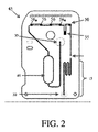
本発明の限定しない実施形態について、添付の図を参照して例として説明する。添付の図は、概略的であり、正確な縮尺であるようには意図されていない。図において、図示する同一または略同一の構成要素の各々は、典型的には、単一の数字によって表されている。明確にするために、当業者が本発明を理解するのを可能にするために例示が不要である場合、すべての図においてすべての構成要素に符号が付されているとは限らず、本発明の各実施形態のすべての構成要素が図示されているとは限らない。 Non-limiting embodiments of the present invention will be described as examples with reference to the accompanying figures. The attached figure is schematic and is not intended to be an exact scale. In the figure, each of the identical or substantially identical components illustrated is typically represented by a single number. For clarity, not all components are coded in all figures and the present invention is not illustrated if illustrations are not needed to allow one of ordinary skill in the art to understand the invention. Not all components of each embodiment of the above are shown.
アッセイ成分の培養および/または混合を含む流体デバイスおよび方法が提供される。いくつかの実施形態では、流体デバイスにおいて、生物学的かつ/または化学的アッセイを行うことができる。流体デバイスは、2つ以上のアッセイ成分(たとえば、試料および試薬)の制御された培養および/または混合を可能にするように設計することができる。いくつかのこうした実施形態では、流体デバイスは、検出チャネルと流体連通する、比較的大きい断面寸法を有する培養チャネルを備えることができる。培養チャネルは、アッセイの分析の前に2つ以上のアッセイ成分の適切な混合および/または培養を可能にすることができる。いくつかの実施形態では、検出チャネルを用いて、たとえば、培養チャネル内の試料成分の存在ならびに/または培養および/もしくは混合の程度に関するフィードバックを提供することができる。フィードバックに基づいて、流体流源等、流体システムの1つまたは複数の構成要素を、達成するべき必要な程度の混合および/または培養を可能にするように調節することができる。いくつかの実施形態では、本明細書に記載するような、培養チャネル内のアッセイ成分の制御された培養および/または混合により、アッセイ性能(たとえば、感度、特異性および/または再現性)を向上させ、アッセイ成分の培養および/または混合に依存するアッセイに対する流体デバイスの設計および動作を簡略化することができる。 Fluid devices and methods are provided that include culturing and / or mixing assay components. In some embodiments, biological and / or chemical assays can be performed on the fluid device. Fluid devices can be designed to allow controlled culture and / or mixing of two or more assay components (eg, samples and reagents). In some such embodiments, the fluid device can include a culture channel with a relatively large cross-sectional dimension that communicates with the detection channel. Culture channels can allow proper mixing and / or culture of two or more assay components prior to assay analysis. In some embodiments, the detection channel can be used, for example, to provide feedback on the presence of sample components in the culture channel and / or the degree of culture and / or mixing. Based on the feedback, one or more components of the fluid system, such as the fluid source, can be adjusted to allow the required degree of mixing and / or culture to be achieved. In some embodiments, controlled culture and / or mixing of assay components within the culture channel, as described herein, improves assay performance (eg, sensitivity, specificity and / or reproducibility). The design and operation of fluid devices for assays that rely on culturing and / or mixing of assay components can be simplified.
生物学的かつ/または化学的アッセイを行うための流体デバイスが存在するが、アッセイ成分の混合および/または培養が不適切であるため、従来の流体デバイスではいくつかのアッセイを容易にかつ/または正確に行うことができない。たとえば、十分な培養は、対象分析物を検出するために、対象分析物を試料内の天然の結合パートナーから放出する必要があるアッセイの重要な部分である。いくつかのこうした実施形態では、放出される、したがって検出される対象分析物の量は、培養時間によって決まり、培養に対する制御が不十分である場合、アッセイの結果が不正確になりかつ/またはアッセイが再現不可能になる。いくつかの実施形態では、アッセイ感度は、培養の長さおよび/または温度によって決まる場合がある。たとえば、検出結合バートナー(たとえば、抗体)に結合された分析物の量は、高温での長期の接触および/または培養によって増大する可能性がある。従来の流体デバイスは、流体デバイスの設計および流体デバイスにおける流体の扱いを変更することにより、この問題に対処しようとしてきた。しかしながら、これらの従来のデバイスの多くは、詰まり等の問題があり、製造が困難である可能性がある複雑なデバイス構造に依存し、かつ/または、たとえばポイントオブケア(point−of−care)環境において、実施することが困難である可能性がある複雑なアッセイ方法に依存する。本明細書に記載する流体デバイスは、多くの従来の流体デバイスの欠点なしに十分な混合および/または培養を可能にすることができ、従来の流体デバイスでは容易にかつ/または正確に実施されなかったアッセイを行うために使用することができる。 There are fluid devices for performing biological and / or chemical assays, but due to improper mixing and / or culture of assay components, conventional fluid devices facilitate and / or perform some assays. It cannot be done accurately. For example, sufficient culture is an important part of the assay in which the subject analyte needs to be released from the natural binding partner in the sample in order to detect the subject analyte. In some of these embodiments, the amount of subject analyte released and thus detected depends on the culture time, and if control over the culture is inadequate, the assay results will be inaccurate and / or the assay. Becomes unreproducible. In some embodiments, assay sensitivity may depend on culture length and / or temperature. For example, the amount of analyte bound to a detection-bound bartner (eg, antibody) can be increased by long-term contact and / or culture at high temperatures. Traditional fluid devices have attempted to address this issue by changing the design of fluid devices and the treatment of fluids in fluid devices. However, many of these conventional devices rely on complex device structures that can be difficult to manufacture due to problems such as clogging and / or, for example, point-of-care. In the environment, it relies on complex assay methods that can be difficult to perform. The fluid devices described herein can allow sufficient mixing and / or culturing without the drawbacks of many conventional fluid devices and are not easily and / or accurately performed with conventional fluid devices. Can be used to perform fluidized assays.
いくつかの実施形態では、流体デバイスにおいて、培養ステップおよび/または混合ステップを含む生物学的かつ/または化学的アッセイを行うことができる。本明細書に記載するように、流体デバイスは、2つ以上のアッセイ成分(たとえば、試料成分および試薬、試薬および希釈剤、試薬および緩衝剤)の制御された培養および/または混合を可能にするように設計することができる。1つの例示的な実施形態では、流体デバイス10は、図1Aに例示的に示すように、培養チャネル15を備える。培養チャネルは、検出チャネル20と流体連通することができる。図1Aに例示的に示すように、検出チャネルは、培養チャネルと検出ゾーン25との間に配置されている。検出ゾーンは、いくつかの分析領域26を含むことができる。しかしながら、他の実施形態では、検出チャネルは、検出ゾーンの一部であり得る(たとえば、検出チャネルは、1つまたは複数の検出器に関連付けられた検出ゾーンのチャネルであり得る)。
In some embodiments, the fluid device can be subjected to a biological and / or chemical assay that includes a culture step and / or a mixing step. As described herein, fluid devices allow controlled culture and / or mixing of two or more assay components (eg, sample components and reagents, reagents and diluents, reagents and buffers). Can be designed as In one exemplary embodiment, the
他の実施形態では、培養チャネルの一部は、検出ゾーンの一部(たとえば、1つまたは複数の検出器に関連付けられた領域)であり得る。こうした構成により、たとえば、培養ステップ中、試料の前縁(たとえば、試料/空気界面)が培養チャネル内に配置されるのを確実にするために、培養チャネルにある間の試料の検出を可能にすることができる。たとえば、図1Bに例示的に示すように、培養チャネル15の一部は、検出ゾーン27を備え、検出チャネル20のいくつかの部分は他の検出ゾーン26を備える。検出ゾーン27で試料が検出されると、培養チャネル内の試料のすべてまたは一部を培養するために、試料を停止させるかまたは流量を低減させることができる。いくつかの実施形態では、検出ゾーン27では、培養チャネル内で試料の結合は実質的に起こらない。
In other embodiments, part of the culture channel can be part of a detection zone (eg, a region associated with one or more detectors). Such a configuration allows detection of the sample while in the culture channel, for example, to ensure that the leading edge of the sample (eg, the sample / air interface) is located within the culture channel during the culture step. can do. For example, as exemplified in FIG. 1B, part of the
いくつかの実施形態では、培養中に培養チャネル内に存在する試料は、流体栓の形態である。たとえば、流体試料の両端においてその側面に空気栓を配置することができ、それにより、第1空気栓、流体試料および第2空気栓は、培養中に培養チャネル内に配置される。 In some embodiments, the sample present in the culture channel during culture is in the form of a fluid plug. For example, air plugs can be placed on the sides thereof at both ends of the fluid sample, whereby the first air plug, the fluid sample and the second air plug are placed in the culture channel during culturing.
いくつかの実施形態では、検出ゾーン27におけるチャネル寸法(および/または断面積)は、たとえば上述したように、検出ゾーン27の上流の培養チャネルの寸法(および/または面積)と同じであるかまたは同様である。したがって、検出ゾーンにおける培養チャネルの寸法(および/または断面積)は、試料成分の結合が起こる可能性がある検出ゾーン25におけるチャネルの寸法(および/または断面積)より大きい可能性がある。
In some embodiments, the channel dimensions (and / or cross-sectional area) in the
培養チャネル、検出チャネルおよび/または検出ゾーンのうちの1つまたは複数をフィードバックシステムに接続することができ、フィードバックシステムを用いて、培養ステップおよび/または混合の1つまたは複数の態様を制御することができる。たとえば、いくつかの実施形態では、検出ゾーンを用いて、試料の少なくとも一部(たとえば、試料の少なくとも約80%)が下流反応エリアに到達する前に試料成分を検出することができる。試料成分に対応する1つもしくは複数の信号またはデータを生成することができる。このデータを用いて、制御システムは、流体デバイス内の後続する流体流を調整することができる。たとえば、データに基づいて、制御システムは、追加の培養または混合を可能にするように、試料の流量を、初期流量より低い流量までかつ/またはゼロまで低減させることができる。いくつかの実施形態では、図1Aに例示する流体デバイスにおける培養および/または混合を制御するように流体流を調整する方法は、試料収集器(たとえば、血液収集器)内に試料を導入することを含むことができる。好適な試料収集器については、後述し、かつ、全体として参照により本明細書に組み込まれる、2012年6月19日に発行され(2008年5月1日に出願され)「Fluidic Connectors and Microfluidic Systems」と題する米国特許第8,202,492号明細書[C1256.70000US01]に記載されている。試料収集器(たとえば、血液収集器)は、1つまたは複数のチャネルを備えることができる。いくつかの実施形態では、試料収集器は、たとえば、試料収集器の少なくとも1つのチャネル面の内側にかつ/またはその少なくとも一部に堆積した、1つまたは複数の試薬を備えることができる。いくつかのこうした例では、試料は、試薬の少なくとも一部を除去し、試薬を溶解させるかまたは懸濁させることができる。しかしながら、他の実施形態では、試料収集器は試薬を含まない。 One or more of the culture channels, detection channels and / or detection zones can be connected to the feedback system and the feedback system is used to control one or more aspects of the culture step and / or mixing. Can be done. For example, in some embodiments, the detection zone can be used to detect sample components before at least a portion of the sample (eg, at least about 80% of the sample) reaches the downstream reaction area. One or more signals or data corresponding to the sample components can be generated. This data can be used by the control system to regulate the subsequent fluid flow within the fluid device. For example, based on the data, the control system can reduce the flow rate of the sample to a flow rate below the initial flow rate and / or to zero to allow additional culture or mixing. In some embodiments, the method of adjusting the fluid flow to control culture and / or mixing in the fluid device illustrated in FIG. 1A is to introduce the sample into a sample collector (eg, a blood collector). Can be included. Suitable sample collectors are described below and incorporated herein by reference in their entirety, published June 19, 2012 (filed May 1, 2008), "Fluidic Controllers and Microfluidic Systems." , US Pat. No. 8,202,492 [C1256.70000US01]. The sample collector (eg, blood collector) can include one or more channels. In some embodiments, the sample collector can include, for example, one or more reagents deposited inside and / or at least a portion of at least one channel surface of the sample collector. In some of these examples, the sample can remove at least a portion of the reagent and dissolve or suspend the reagent. However, in other embodiments, the sample collector does not contain reagents.
図1Aおよび図1Bを参照すると、試料を収容する試料収集器は、その後、流体デバイスの試料入口ポート30に接続することができる。試料収集器は、いくつかの実施形態では流体コネクタであり得る。いくつかの実施形態では、試料収集器は、試料収集器の接続の前は互いに流体連通していなかった流体デバイスの2つのチャネルの間に、流体連通を提供することができる。たとえば、いくつかの実施形態では、チャネルを備えた試料収集器を用いて、2つの独立したチャネルの間の流体連通を可能にするように、流体デバイスにおいて2つの独立したチャネルを接続する。独立したチャネルの一方または両方に対して、任意選択的に、分析を行うために使用することができる試薬(たとえば、抗体溶液、洗浄緩衝剤および増幅試薬)によって予め充填することができる。これらの試薬は、使用する前に長期間(たとえば、1年間)、基板のチャネル内に保管(たとえば、封入)することができる。試料収集器および流体デバイスを接続する前に、試料収集器のチャネルに試料(たとえば、血液)を充填することができる。試料は、たとえば、血液が指からチャネル内に(たとえば、毛管力によって)引き込まれるまで、使用者の指を穿刺することによって、得ることができる。試料収集器と流体デバイスのチャネルとを接続すると、試料は、流体デバイス内の検出ゾーンおよび/または分析領域を通過することができる。
With reference to FIGS. 1A and 1B, the sample collector containing the sample can then be connected to the
試料収集器が流体デバイスに接続される実施形態では、流体流源ポート35(たとえば、出口)に容積または圧力源を接続することができ、かけられる力(たとえば、真空または減圧)により、試料は流体デバイス内に流れ込むことができる。いくつかの実施形態では、試料は、試料入口ポートに入る前に培養チャネル内に直接流れ込むことができる。他の実施形態では、試料は、培養チャネルに入る前に別の構造(たとえば、チャネル)に入ることができる。いくつかの場合では、培養チャネルは、1つまたは複数の寸法(たとえば、長さ、幅、高さ)および/または培養チャネルが試料の実質的にすべて(たとえば、試料の体積の少なくとも約80%、試料の体積の少なくとも約95%、試料全体)を収容するのを可能にする容積を有することができる。たとえば、培養チャンバは、少なくとも約0.0005mL、少なくとも約0.001mL、0.005mL、少なくとも約0.01mL、少なくとも約0.02mL、少なくとも約0.03mL、少なくとも約0.05mL、少なくとも約0.08mLまたは少なくとも約0.01mL、かつ約1mL以下、約0.75mL以下、約0.5mL以下、約0.25mL以下または約0.1mL以下の体積を有する試料を収容するように構成することができる。上述した範囲のすべての組合せが可能である。いくつかの場合では、培養チャネルの容積は、試料の体積と同様であり得る。たとえば、いくつかの実施形態では、培養チャネルの容積の試料の体積に対する比は、約3:1以下、約2.5:1以下、約2:1以下、約1.5:1以下または約1:1以下、かつ少なくとも約0.6:1、少なくとも約0.7:1、少なくとも約0.8:1または少なくとも約0.9:1であり得る。上述した範囲のすべての組合せが可能である。いくつかの実施形態では、培養チャネルは、流体デバイスにおける別のチャネル(たとえば、検出チャネル)より大きい断面積を有することができる。他の実施形態では、培養チャネルは、たとえば、試料の比較的大きい割合を収容することができないように、容積が試料の体積より小さいように設計される。 In embodiments where the sample collector is connected to a fluid device, a volume or pressure source can be connected to the fluid source port 35 (eg, outlet) and the applied force (eg, vacuum or decompression) causes the sample to be It can flow into a fluid device. In some embodiments, the sample can flow directly into the culture channel before entering the sample inlet port. In other embodiments, the sample can enter another structure (eg, channel) before entering the culture channel. In some cases, the culture channel has one or more dimensions (eg, length, width, height) and / or the culture channel is substantially all of the sample (eg, at least about 80% of the volume of the sample). , Can have a volume that allows at least about 95% of the volume of the sample, the entire sample) to be accommodated. For example, the culture chamber is at least about 0.0005 mL, at least about 0.001 mL, 0.005 mL, at least about 0.01 mL, at least about 0.02 mL, at least about 0.03 mL, at least about 0.05 mL, at least about 0. It may be configured to contain a sample having a volume of 08 mL or at least about 0.01 mL and about 1 mL or less, about 0.75 mL or less, about 0.5 mL or less, about 0.25 mL or less or about 0.1 mL or less. can. All combinations in the range described above are possible. In some cases, the volume of the culture channel can be similar to the volume of the sample. For example, in some embodiments, the ratio of culture channel volume to sample volume is about 3: 1 or less, about 2.5: 1 or less, about 2: 1 or less, about 1.5: 1 or less, or about. It can be 1: 1 or less and at least about 0.6: 1, at least about 0.7: 1, at least about 0.8: 1 or at least about 0.9: 1. All combinations in the range described above are possible. In some embodiments, the culture channel can have a larger cross-sectional area than another channel in the fluid device (eg, a detection channel). In other embodiments, the culture channel is designed, for example, to be smaller in volume than the volume of the sample so that it cannot accommodate a relatively large proportion of the sample.
いくつかの実施形態では、試料(または試薬)の少なくとも一部が、ある期間、培養チャネル内で培養される。本明細書に記載するように、培養ステップ中に、試料の流れを停止させることができ、または流量を低減させることができる。たとえば、いくつかの実施形態では、少なくとも1分、少なくとも3分、少なくとも5分、少なくとも7分、少なくとも9分、少なくとも11分、少なくとも13分、少なくとも15分、少なくとも17分、少なくとも19分、少なくとも20分、少なくとも30分、少なくとも40分、少なくとも50分、少なくとも60分の時間、(たとえば、培養チャネル、および/または本明細書に記載する検出チャネルの一部の中で)培養することができる。時間は、60分以下、50分以下、40分以下、30分以下、20分以下、19分以下、17分以下、15分以下、13分以下、12分以下、11分以下、10分以下、9分以下、7分以下、5分以下、3分以下または1分以下であり得る。上述した範囲の組合せも可能である(たとえば、少なくとも5分かつ15分以下)。他の範囲も可能である。 In some embodiments, at least a portion of the sample (or reagent) is cultured in the culture channel for a period of time. As described herein, the flow of the sample can be stopped or the flow rate can be reduced during the culture step. For example, in some embodiments, at least 1 minute, at least 3 minutes, at least 5 minutes, at least 7 minutes, at least 9 minutes, at least 11 minutes, at least 13 minutes, at least 15 minutes, at least 17 minutes, at least 19 minutes, at least. It can be cultured for 20 minutes, at least 30 minutes, at least 40 minutes, at least 50 minutes, at least 60 minutes (eg, within a culture channel and / or some of the detection channels described herein). .. The time is 60 minutes or less, 50 minutes or less, 40 minutes or less, 30 minutes or less, 20 minutes or less, 19 minutes or less, 17 minutes or less, 15 minutes or less, 13 minutes or less, 12 minutes or less, 11 minutes or less, 10 minutes or less. , 9 minutes or less, 7 minutes or less, 5 minutes or less, 3 minutes or less or 1 minute or less. Combinations of the above ranges are also possible (eg, at least 5 minutes and 15 minutes or less). Other ranges are possible.
試料または試薬は、任意の好適な温度で培養することができる。いくつかの実施形態では、少なくとも15℃の温度(たとえば、培養温度)で、少なくとも20℃の温度で、少なくとも25℃で、少なくとも30℃、少なくとも35℃、少なくとも40℃、少なくとも45℃、少なくとも50℃、少なくとも55℃または少なくとも60℃の温度で、試料または試薬を(たとえば、培養チャネル、および/または本明細書に記載する検出チャネルの一部の中で)培養することができる。温度は、65℃以下、60℃以下、55℃以下、50℃以下、45℃以下、40℃以下、35℃以下、30℃以下または25℃以下であり得る。上述した範囲の組合せも可能である(たとえば、少なくとも45℃かつ55℃以下)。他の範囲も可能である。 The sample or reagent can be cultured at any suitable temperature. In some embodiments, at least 15 ° C. (eg, culture temperature), at least 20 ° C., at least 25 ° C., at least 30 ° C., at least 35 ° C., at least 40 ° C., at least 45 ° C., at least 50. The sample or reagent can be cultured at a temperature of ° C., at least 55 ° C. or at least 60 ° C. (eg, within a culture channel and / or part of the detection channel described herein). The temperature can be 65 ° C. or lower, 60 ° C. or lower, 55 ° C. or lower, 50 ° C. or lower, 45 ° C. or lower, 40 ° C. or lower, 35 ° C. or lower, 30 ° C. or lower or 25 ° C. or lower. Combinations in the above ranges are also possible (eg, at least 45 ° C and 55 ° C or less). Other ranges are possible.
いくつかの実施形態では、容積または圧力源は、試料の少なくとも一部が培養チャネル内に流れ込むように、所定の長さの時間、所定の設定に調整することができる。いくつかのこうした実施形態では、培養チャネルに、たとえば、培養チャネルが試料で充填されたか否かを検出する検出器は不要であり、または存在しない。代わりに、所定の容積または圧力源の設定および時間(たとえば、真空レベルおよび真空をかける時間)を含む、培養チャネルの充填は、試料のタイプおよびその特性(たとえば、全血、指穿刺から採取される毛管全血、静脈全血、血漿、血清、尿、唾液等、その粘度を含む)とともに、培養チャネルまでかつ培養チャネルを含むチャネル寸法(たとえば、幅、高さ、長さ、およびそれにより流体流に対する抵抗)に基づいて、判定し調整することができる。圧力源レベルと圧力源の圧力をかけるタイミングとは、特定の用途に対して適合させることができる。 In some embodiments, the volume or pressure source can be adjusted to a given setting for a given length of time so that at least a portion of the sample flows into the culture channel. In some such embodiments, the culture channel does not require or is present, for example, a detector that detects whether the culture channel is filled with a sample. Instead, the filling of the culture channel, including the setting and time of a given volume or pressure source (eg, plasma level and time to apply vacuum), is taken from the type of sample and its properties (eg, whole blood, finger puncture). Channel dimensions (eg, width, height, length, and thereby fluid) up to and including the culture channel, along with whole blood ducts, whole veins, plasma, serum, urine, saliva, etc., including their viscosity. It can be determined and adjusted based on the resistance to flow). The pressure source level and the timing of applying pressure from the pressure source can be adapted for a particular application.
いくつかの実施形態では、培養ステップ時に、試料の少なくとも一部(ただし、すべてではない)が培養チャネルに入る。いくつかの場合では、試料は、培養チャネルに入るが、検出チャネル、検出ゾーン、廃棄物ゾーンまたはデバイスの出口等、いかなる下流のチャネルにも入らない。他の実施形態では、試料の少なくとも一部は培養チャネルに入るが、試料の前縁(たとえば、空気/試料界面)は、断面積の範囲内で培養チャネルの下流のチャネルに入らず、またはそこで停止しない。たとえば、試料の前縁が比較的大きい断面積を有するチャネルに達するときに、試料を停止させることができ、または培養のために流量を低減させることができ、それにより、培養中および/または培養後、試料がチャネルに詰まることがない。概して、いくつかの試料は(特に、試料/空気界面において)、試料の乾燥、凝固および/または凝結のために、比較的小さい断面積を有するチャネル内で詰まる傾向が高く、それにより、試料流が再開したときの流体流に対する抵抗が高くなる可能性がある。 In some embodiments, at least some (but not all) of the sample enters the culture channel during the culture step. In some cases, the sample enters the culture channel but not in any downstream channel, such as the detection channel, detection zone, waste zone or device exit. In other embodiments, at least a portion of the sample enters the culture channel, but the leading edge of the sample (eg, the air / sample interface) does not or does not enter the channel downstream of the culture channel within the cross-sectional area. Do not stop. For example, the sample can be stopped when the leading edge of the sample reaches a channel with a relatively large cross-sectional area, or the flow rate can be reduced for culturing, thereby during and / or culturing. After that, the sample does not clog the channel. In general, some samples (especially at the sample / air interface) are more likely to clog in channels with a relatively small cross-sectional area due to sample drying, coagulation and / or condensation, thereby causing sample flow. May increase resistance to fluid flow when resuming.
いくつかの実施形態では、この詰まる傾向は、試料が所定の断面積を有するチャネルに達したときに、試料(試料/空気界面等、試料の前縁を含む)を停止させるかまたは流量を低減させることにより、対処することができる。チャネルの断面積は、少なくとも0.008mm2、少なくとも0.01mm2、少なくとも0.02mm2、少なくとも0.03mm2、少なくとも0.04mm2、少なくとも0.05mm2、少なくとも0.06mm2、少なくとも0.08mm2、少なくとも0.10mm2、少なくとも0.12mm2、少なくとも0.14mm2、少なくとも0.16mm2、少なくとも0.18mm2、少なくとも0.20mm2、少なくとも0.30mm2、少なくとも0.40mm2、少なくとも0.50mm2、少なくとも0.60mm2、少なくとも0.70mm2、少なくとも0.80mm2、少なくとも0.90mm2または少なくとも1.00mm2であり得る。いくつかの実施形態では、断面積は、1.00mm2以下、0.90mm2以下、0.80mm2以下、0.70mm2以下、0.60mm2以下、0.50mm2以下、0.40mm2以下、0.30mm2以下、0.25mm2以下、0.20mm2以下、0.175mm2以下、0.15mm2以下、0.1mm2以下、0.05mm2以下、0.04mm2以下、0.02mm2以下、0.015mm2または0.010mm2以下であり得る。上述した範囲の組合せも可能である。他の範囲も可能である。いくつかの実施形態では、培養チャネルは、上述した範囲のうちの1つまたは複数の断面積を有する。 In some embodiments, this clogging tendency causes the sample (including the leading edge of the sample, such as the sample / air interface) to stop or reduce flow rate when the sample reaches a channel with a given cross-sectional area. It can be dealt with by making it. Cross-sectional area of the channel is at least 0.008 mm 2, at least 0.01 mm 2, at least 0.02 mm 2, at least 0.03 mm 2, at least 0.04 mm 2, at least 0.05 mm 2, at least 0.06 mm 2, at least 0 .08mm 2, at least 0.10 mm 2, at least 0.12 mm 2, at least 0.14 mm 2, at least 0.16 mm 2, at least 0.18 mm 2, at least 0.20 mm 2, at least 0.30 mm 2, at least 0.40mm 2, at least 0.50 mm 2, at least 0.60 mm 2, at least 0.70 mm 2, at least 0.80 mm 2, it can be at least 0.90 mm 2, or at least 1.00 mm 2. In some embodiments, the cross-sectional area, 1.00 mm 2 or less, 0.90 mm 2 or less, 0.80 mm 2 or less, 0.70 mm 2 or less, 0.60 mm 2 or less, 0.50 mm 2 or less, 0.40 mm 2 or less, 0.30 mm 2 or less, 0.25 mm 2 or less, 0.20 mm 2 or less, 0.175 mm 2 or less, 0.15 mm 2 or less, 0.1 mm 2 or less, 0.05 mm 2 or less, 0.04 mm 2 or less , 0.02 mm 2 or less, it may be 0.015 mm 2 or 0.010 mm 2 or less. Combinations of the above ranges are also possible. Other ranges are possible. In some embodiments, the culture channel has one or more cross-sectional areas within the range described above.
いくつかの実施形態では、検出ゾーンの検出チャネル(たとえば、試料成分の結合が起こる場所)は、培養チャネルの断面積より小さい断面積を有する。検出ゾーンの検出チャネルは、たとえば、少なくとも0.001mm2、少なくとも0.002mm2、0.004mm2、0.005mm2、0.006mm2、0.008mm2、少なくとも0.01mm2、少なくとも0.02mm2、少なくとも0.03mm2、少なくとも0.04mm2、少なくとも0.05mm2、少なくとも0.06mm2、少なくとも0.08mm2または少なくとも0.10mm2の断面積を有することができる。いくつかの実施形態では、断面積は、0.016mm2以下、0.014mm2以下、0.012mm2以下、0.010mm2以下、0.008mm2以下、0.006mm2以下、0.005mm2、または0.004mm2以下、0.003mm2または0.002mm2以下であり得る。上述した範囲の組合せも可能である。他の範囲も可能である。 In some embodiments, the detection channel of the detection zone (eg, where the binding of sample components occurs) has a cross-sectional area smaller than the cross-sectional area of the culture channel. Detection channels of the detection zone, for example, at least 0.001 mm 2, at least 0.002mm 2, 0.004mm 2, 0.005mm 2 , 0.006mm 2, 0.008mm 2, at least 0.01 mm 2, at least 0. 02mm 2, at least 0.03 mm 2, at least 0.04 mm 2, at least 0.05 mm 2, at least 0.06 mm 2, may have a cross-sectional area of at least 0.08 mm 2, or at least 0.10 mm 2. In some embodiments, the cross-sectional area, 0.016 mm 2 or less, 0.014 mm 2 or less, 0.012 mm 2 or less, 0.010 mm 2 or less, 0.008 mm 2 or less, 0.006 mm 2 or less, 0.005 mm 2, or 0.004 mm 2 or less, it may be 0.003 mm 2 or 0.002 mm 2 or less. Combinations of the above ranges are also possible. Other ranges are possible.
いくつかの実施形態では、試料は、培養チャネルを通って流れることができ、試料の一部は、検出チャネルに達することができる。本明細書に記載するように、いくつかの実施形態では、検出チャネルは、培養チャネルより著しく小さい断面積を有することができる。したがって、検出チャネルの内側の流量および/または検出チャネルの容積は、培養チャネルの流量および/または容積より著しく小さい可能性がある。いくつかの実施形態では、試料の少なくとも一部は、検出領域(たとえば、検出チャネルおよび/または検出ゾーン)に入ることができ、それにより、試料もしくは試料成分の存在もしくは不在および/または試料もしくは試料成分の1つもしくは複数の特徴が検出される。いくつかのこうした実施形態では、試料の一部は、検出領域(たとえば、検出チャネル、検出ゾーン)の一部(ただし、すべてではない)に流れ込むことができる。いくつかの実施形態では、試料のわずかな割合(たとえば、約10%以下、約5%以下)が、こうした分析を開始するために検出領域に流れ込むことができる。こうした検出から生成される1つまたは複数の信号は、制御システムに送信することができる。たとえば、検出は、光吸収または透過測定を介して試料の存在を検出することを含むことができる。 In some embodiments, the sample can flow through the culture channel and a portion of the sample can reach the detection channel. As described herein, in some embodiments, the detection channel can have a significantly smaller cross-sectional area than the culture channel. Therefore, the flow rate and / or volume of the detection channel inside the detection channel can be significantly smaller than the flow rate and / or volume of the culture channel. In some embodiments, at least a portion of the sample can enter the detection region (eg, detection channel and / or detection zone), whereby the presence or absence of the sample or sample component and / or the sample or sample. One or more features of the component are detected. In some such embodiments, a portion of the sample can flow into some (but not all) of the detection region (eg, detection channel, detection zone). In some embodiments, a small percentage of the sample (eg, about 10% or less, about 5% or less) can flow into the detection area to initiate such an analysis. One or more signals generated from such detection can be transmitted to the control system. For example, detection can include detecting the presence of a sample via light absorption or transmission measurements.
いくつかの場合では、検出からのフィードバックを用いて、流体システムの1つまたは複数の構成要素を、流量を調整するように変更することができる。たとえば、検出ゾーンを通過する試料の検出により、培養チャネル内の流体流を調整するために特定の弁が駆動されるか否かの制御をトリガすることができる。いくつかのこうした実施形態では、試料の検出から生成される1つまたは複数の信号を、1つまたは複数の事前設定値と比較することができ、(少なくとも一部には)このフィードバックおよび比較に基づいて、制御システムは、測定信号が事前設定値との範囲外である場合、培養チャネルおよび/または流体デバイスの他の部分(たとえば、流体デバイス全体)内の流体流を調整する(たとえば、中止するかまたは低減させる)ことができる。いくつかの場合では、デバイスの一部分の流体流は、たとえば、通気弁等の弁を用いて、デバイスの別の部分とは別個に調節することができる。流体流を調節するための通気弁については、全体として参照により本明細書に組み込まれる、「Fluid Mixing and Delivery in Microfluidic Systems」と題する、2010年11月24日に出願された米国特許出願公開第2011/0120562号明細書[C1256.70005US01]に記載されている。 In some cases, feedback from the detection can be used to modify one or more components of the fluid system to regulate the flow rate. For example, detection of a sample passing through a detection zone can trigger control over whether a particular valve is driven to regulate fluid flow within the culture channel. In some such embodiments, one or more signals generated from sample detection can be compared to one or more preset values, and (at least in part) to this feedback and comparison. Based on this, the control system regulates (eg, discontinues) the fluid flow within the culture channel and / or other parts of the fluid device (eg, the entire fluid device) if the measurement signal is outside the preset values. Or reduce). In some cases, the fluid flow in one part of the device can be regulated separately from the other part of the device, for example using a valve such as a vent valve. For vent valves for regulating fluid flow, US Patent Application Publication No. 24, filed November 24, 2010, entitled "Fluid Mixing and Delivery in Microfluidic Systems," which is incorporated herein by reference in its entirety. 2011/0120562 is described in the specification [C1256.70005US01].
いくつかの実施形態では、信号からの情報に基づき、流量を増減させるように、容積または圧力源を調整することができ、または他の場合では、流量を維持することができる。一例では、試料は、検出前は(たとえば、検出ゾーン等の検出領域において)第1流量を有することができ、検出後は第2流量を有することができる。第2流量は、第1流量より著しく低い可能性がある。たとえば、第2流量は、第1流量の約50%以下(たとえば、約40%以下、約30%以下、約20%以下、約10%以下、約5%以下、約1%以下)であり得る。いくつかの場合では、第2流量はゼロであり得る。流量の低減により、試料の残りの部分が培養チャネルを離れかつ/または反応エリア/分析領域等、所定の下流位置に達する前に、十分な培養および/または混合が発生するのを可能にすることができる。他の実施形態では、第2流量は、第1流量以上であり得る。 In some embodiments, the volume or pressure source can be adjusted to increase or decrease the flow rate based on the information from the signal, or in other cases the flow rate can be maintained. In one example, the sample can have a first flow rate before detection (eg, in a detection area such as a detection zone) and a second flow rate after detection. The second flow rate can be significantly lower than the first flow rate. For example, the second flow rate is about 50% or less of the first flow rate (for example, about 40% or less, about 30% or less, about 20% or less, about 10% or less, about 5% or less, about 1% or less). obtain. In some cases, the second flow rate can be zero. The reduced flow rate allows sufficient culture and / or mixing to occur before the rest of the sample leaves the culture channel and / or reaches a predetermined downstream position, such as the reaction area / analytical region. Can be done. In other embodiments, the second flow rate can be greater than or equal to the first flow rate.
いくつかの実施形態では、検出ゾーンにおける試料のその部分が分析領域および/または別の下流検出ゾーンに達するのを阻止するために、流体デバイスは、図2に例示的に示すように、検出ゾーン50と流体デバイスの下流の特徴(たとえば、追加の分析領域56)との間に追加のチャネル55を備えることができる。分析領域56において試料の成分を検出する結果として、試料が混合チャネル内でさらに培養されるかまたは混合されるように、流体流を終わらせるかまたは低減させることができる。十分な培養または混合の後、試料は、検出ゾーンの残りの分析領域に向かい続けることができ、そこで、試料の成分を検出しかつ/または分析することができる。
In some embodiments, in order to prevent that portion of the sample in the detection zone from reaching the analytical region and / or another downstream detection zone, the fluid device is configured in the detection zone, as exemplary in FIG. An
検出領域において試料または試料成分が検出された後に流量が調整されるいくつかの実施形態では、アッセイに基づいて事前設定するかまたは試料もしくは試料成分の後続する検出によって求めることができる所定期間の後、流量は、第2流量を超えるかまたは第2流量未満である第3流量に調整することができる。たとえば、事前設定された培養時間の後、流量は、第2流量より高い第3流量まで増大することができる。第3流量は、第1流量を超えるか、第1流量未満であるか、またはそれに等しい場合がある。いくつかの実施形態では、流体デバイスは、流体デバイス内の後続する動作(たとえば、流体流)に悪影響を与えることなく、流体流が著しく速度を低下させるかまたは停止するのを可能にするように構成することができる。たとえば、詰まりが発生することなく、流体デバイス内で流体流を停止させかつ再開させることができる。 In some embodiments where the flow rate is adjusted after the sample or sample component is detected in the detection region, after a predetermined period of time that can be preset based on the assay or determined by subsequent detection of the sample or sample component. , The flow rate can be adjusted to a third flow rate that is greater than or less than the second flow rate. For example, after a preset culture time, the flow rate can be increased to a third flow rate higher than the second flow rate. The third flow rate may be greater than, less than, or equal to the first flow rate. In some embodiments, the fluid device allows the fluid flow to significantly slow down or stop without adversely affecting subsequent movements within the fluid device (eg, fluid flow). Can be configured. For example, the fluid flow can be stopped and resumed within the fluid device without clogging.
いくつかの実施形態では、方法は、培養ステップが発生した後に、試料、試薬および/またはチャネル(たとえば、培養チャネル、または検出ゾーンのチャネル)の温度を、培養ステップ中に使用された温度より低い温度まで低下させることをさらに含むことができる。たとえば、検出ステップ中に温度を低下させることができる。こうした温度低下により、いくつかの実施形態では、検出ゾーンを通る試料の流量を改善しかつ/または増大させることができる。たとえば、温度は、60℃以下、55℃以下、50℃以下、45℃以下、40℃以下、37℃以下、35℃以下、30℃以下または25℃以下まで低下させることができる。いくつかの実施形態では、温度は、少なくとも15℃、少なくとも20℃、少なくとも25℃、少なくとも30℃、少なくとも35℃、少なくとも40℃、少なくとも45℃、少なくとも50℃または少なくとも55℃であり得る。上述した範囲の組合せも可能である(たとえば、少なくとも20℃かつ55℃以下)。本明細書に記載する第1温度または第3温度は、各々、上述した範囲のうちの1つまたは複数において独立して値を有することができる。 In some embodiments, the method lowers the temperature of the sample, reagent and / or channel (eg, culture channel, or channel in the detection zone) below the temperature used during the culture step after the culture step has occurred. It can further include lowering to temperature. For example, the temperature can be reduced during the detection step. Such temperature reduction can improve and / or increase the flow rate of the sample through the detection zone in some embodiments. For example, the temperature can be lowered to 60 ° C. or lower, 55 ° C. or lower, 50 ° C. or lower, 45 ° C. or lower, 40 ° C. or lower, 37 ° C. or lower, 35 ° C. or lower, 30 ° C. or lower or 25 ° C. or lower. In some embodiments, the temperature can be at least 15 ° C, at least 20 ° C, at least 25 ° C, at least 30 ° C, at least 35 ° C, at least 40 ° C, at least 45 ° C, at least 50 ° C or at least 55 ° C. Combinations in the above ranges are also possible (eg, at least 20 ° C and 55 ° C or less). The first or third temperatures described herein can each have an independent value in one or more of the above ranges.
したがって、いくつかの実施形態では、方法は、第1温度(たとえば、低い方の温度に対して上述した温度を含む、本明細書に記載する1つまたは複数の範囲における温度)を有する試料または試薬(または、培養チャネル等のチャネル)を含むことができる。そして、第2温度で、試料または試薬を培養することができ(または、チャネルを第2温度にさらすことができ)、第2温度は第1温度より高い。第2温度は、培養温度に対して本明細書に記載したような値を有することができる。そして、試料または試薬(またはチャネル)は第3温度を有することができ、または第3温度にさらすことができ、第3温度は第2温度より低い。第3温度は、低い方の温度に対して上述した温度を含む、本明細書に記載する1つまたは複数の範囲における温度であり得る。いくつかの場合では、第3温度は、第1温度と同じであるが、異なる第1温度および第3温度も可能である。いくつかの場合では、たとえば、第3温度は第1温度より高いが、第2温度より低い。 Thus, in some embodiments, the method is a sample having a first temperature (eg, a temperature in one or more ranges described herein, including the temperature described above relative to the lower temperature). Reagents (or channels such as culture channels) can be included. Then, at the second temperature, the sample or reagent can be cultured (or the channel can be exposed to the second temperature), and the second temperature is higher than the first temperature. The second temperature can have a value as described herein with respect to the culture temperature. The sample or reagent (or channel) can then have a third temperature or be exposed to a third temperature, which is lower than the second temperature. The third temperature can be a temperature in one or more ranges described herein, including the temperature described above relative to the lower temperature. In some cases, the third temperature is the same as the first temperature, but different first and third temperatures are possible. In some cases, for example, the third temperature is higher than the first temperature but lower than the second temperature.
上述したように、制御された培養および/または混合期間の後、試料の残りの部分を、本明細書に記載したような検出ゾーンとは別個であるかまたはその一部であり得る検出チャネルを通して流すことができる。いくつかの場合では、検出チャネルは、検出チャネルの少なくとも1つの表面の少なくとも一部に堆積した試薬を備えることができる。試薬は、試料内の別の試薬または試料成分と相互作用する(たとえば、結合する、反応する)ことができる。検出チャネルから、試料は、1つまたは複数の分析領域/反応エリアを含む流体デバイスの他の下流構成要素を通過することができる。図1Aに示すように、過剰な試料および/または他のアッセイ成分(たとえば、試薬)は、流体デバイスの廃棄物チャンバ40内に収集することができる。
As mentioned above, after a controlled culture and / or mixing period, the rest of the sample is passed through a detection channel that may be separate or part of the detection zone as described herein. Can be shed. In some cases, the detection channel can comprise reagents deposited on at least a portion of the surface of at least one of the detection channels. A reagent can interact (eg, bind, react) with another reagent or sample component in the sample. From the detection channel, the sample can pass through other downstream components of the fluid device, including one or more analytical regions / reaction areas. As shown in FIG. 1A, excess sample and / or other assay components (eg, reagents) can be collected in the
本明細書に記載するように、流体デバイスは、流体デバイスの動作に悪影響を与えることなく、制御された流体の取扱いを可能にするように構成することができる。たとえば、流体デバイスのチャネル内の詰まりなしに、培養チャネル内の流体流を終わらせかつ再開させることができる。多くの従来の流体デバイスでは、本明細書に記載するいくつかの実施形態における培養チャネルから検出チャネルへの遷移部のような、大きい断面積から小さい断面積へのチャネルの幾何学的形状の遷移部が、流体デバイスの動作に悪影響を与える可能性がある。たとえば、流体デバイスが多相流体流に対して使用され(たとえば、液体栓に隣接する気体栓)、チャネルの断面積の遷移部を含むいくつかの実施形態では、詰まり、液滴形成および/または流体の閉じ込め等の望ましくないプロセスが発生する可能性がある。図3に、幾何学的な遷移部における流体の詰まりの例を示す。図3は、小さい断面積を有するチャネルに隣接する大きい断面積を有するチャネルの接合部の画像を示す。接合部において、気泡60が閉じ込められ、液体65の流れを阻止する詰まりとして作用する。幾何学的狭窄部に閉じ込められた気泡60は、(閉じ込められた気泡60の何分の1に等しい体積を有する)複数の小さい気泡を流す可能性があり、その結果、一続きの気泡が、狭窄部の下流に存在することになる。下流チャネルに存在する各気泡は、流れに対する抵抗を増大させ、複数の気泡の存在により、いくつかの場合では、流量が略流れのない状態まで低減する可能性がある(たとえば、それらがチャネルを詰まらせる可能性がある)。比較的大きい断面積を有するチャネルと比較的小さい断面積を有するチャネルとの間の幾何学的形状の変化に対して、幾何学的形状の変化部においていかなる気泡も閉じ込められないように設計することができる。
As described herein, the fluid device can be configured to allow controlled fluid handling without adversely affecting the operation of the fluid device. For example, the fluid flow in the culture channel can be terminated and resumed without clogging in the channel of the fluid device. In many conventional fluid devices, the geometry transition of the channel from a large cross-sectional area to a small cross-sectional area, such as the transition from the culture channel to the detection channel in some embodiments described herein. Parts can adversely affect the operation of the fluid device. For example, a fluid device is used for a polyphase fluid flow (eg, a gas plug adjacent to a liquid plug), and in some embodiments including transitions in the cross-sectional area of the channel, clogging, droplet formation and / or Unwanted processes such as fluid confinement can occur. FIG. 3 shows an example of fluid clogging at a geometric transition. FIG. 3 shows an image of a junction of channels with a large cross-sectional area adjacent to a channel with a small cross-sectional area. At the joint, the
図4は、幾何学的遷移部における液滴形成を例示する一続きの画像を示す。図4Aは、気体流体栓75の下流における液体栓70を示す。液体栓は、断面積が小さい方のチャネルに入っており、気体栓は、断面積が小さい方のチャネルに入り始めている。液体栓がこの接合部を通って流れ、その後、空気栓75が流れる際、図4Bおよび図4Cに示すように、接合部において少量の液体80が捕捉される。図4Dに示すように、この液体は、空気流に形成される液滴源としての役割を果たす可能性があり、下流に分析上の問題をもたらす可能性がある。さらに、複数の流体からの閉じ込められた流体がこの接合部で混合し、結合して、下流の反応に影響を与える可能性がある液滴を形成する可能性がある。
FIG. 4 shows a series of images exemplifying droplet formation at the geometric transition. FIG. 4A shows a
流体デバイスは、本明細書に記載するように、詰まり、1つまたは複数の流体の閉じ込め、気泡の形成、および/または不適切な時点での閉じ込められた流体の解放を回避するように設計することができる。いくつかの実施形態では、培養チャネルと検出チャネルとの間の接合部は、これらの問題を防止するように構成することができる。たとえば、いくつかの実施形態では、流体デバイスは、物品の2つの面に配置されたチャネルを含むことができる。チャネルは、たとえば、流体デバイスのチャネルを形成するために使用される物品の厚さを貫通する、介在チャネルによって接続することができる。介在チャネルは、2つの異なる平面に位置する2つのチャネルを接続するチャネルを指す。チャネルの具体的な幾何学的形状と、本明細書に記載する流体デバイス内のチャネルの位置とにより、1つまたは複数の流体の詰まりおよび/または閉じ込めを回避することができる。たとえば、(たとえば、物品の厚さを貫通する)介在チャネルが存在することにより、比較的大きい断面寸法を有する培養チャネルを、図3に示すように流体の詰まりおよび/または閉じ込めの原因となるチャネルの断面寸法の急峻な変化なしに、比較的小さい断面寸法を有する検出チャネルに流体的に接続することができる。 Fluid devices are designed to avoid clogging, confinement of one or more fluids, formation of bubbles, and / or release of confined fluids at inappropriate times, as described herein. be able to. In some embodiments, the junction between the culture channel and the detection channel can be configured to prevent these problems. For example, in some embodiments, the fluid device can include channels arranged on two sides of the article. The channels can be connected, for example, by intervening channels that penetrate the thickness of the article used to form the channels of the fluid device. An intervening channel refers to a channel that connects two channels located in two different planes. The specific geometry of the channel and the location of the channel within the fluid device described herein can avoid clogging and / or confinement of one or more fluids. For example, the presence of intervening channels (eg, penetrating the thickness of an article) causes culture channels with relatively large cross-sectional dimensions to cause fluid clogging and / or confinement, as shown in FIG. It is possible to fluidly connect to a detection channel having a relatively small cross-sectional dimension without abrupt changes in the cross-sectional dimension of.
いくつかの実施形態では、非円形断面を有するチャネル(たとえば、培養チャネル、検出チャネル)が、物品の第1面および/または第2面に製作される。物品の第1面におけるチャネルは、介在チャネルを介して物品の第2面にあるチャネルに接続され、介在チャネルは、いくつかの実施形態では、円形断面を有することができ、物品の厚さを第1面から第2面まで貫通することができる。このように、第1面にあるチャネルの各々を第2面にあるチャネルに流体的に接続して、単一の連続チャネルを形成することができる。こうした構成の利点は、製作の観点から、平面の表面に、非円形断面を有するチャネルを容易に製作することができ、物品の2つの表面の間の貫通穴の形態で、円形断面を有するチャネルを容易に製作することができる、ということである。 In some embodiments, channels with a non-circular cross section (eg, culture channels, detection channels) are made on the first and / or second surfaces of the article. The channel on the first surface of the article is connected to the channel on the second surface of the article via an intervening channel, which in some embodiments can have a circular cross section to increase the thickness of the article. It can penetrate from the first surface to the second surface. In this way, each of the channels on the first surface can be fluidly connected to the channels on the second surface to form a single continuous channel. The advantage of such a configuration is that, from a manufacturing point of view, a channel with a non-circular cross section can be easily made on a flat surface and a channel with a circular cross section in the form of a through hole between the two surfaces of the article. It means that it can be easily manufactured.
さらに、いくつかの実施形態では、介在チャネルの使用により、たとえば、利用することができる製作方法を拡張することにより、流体デバイスの製作を簡略化することも可能である。たとえば、流体デバイスが、少なくとも一部には射出成形によって形成される実施形態では、成形部分のチャネルは、表面に逆の特徴を含む工具インサートによって画定される。物品の単一の表面における所与のチャネルに対して、チャネルを画定する特徴は、単一の一体的部品(たとえば、単一の構成要素または基板)にあることが好ましいことが多い。2つの部品にわたってチャネルを横切らせることは問題である可能性がある。たとえば、特徴を完全に一列に並べることは困難である可能性があり、それにより、チャネルが不完全になる。2つの部品の間の接触面がバリをもたらす可能性があり、そこで、物品を形成するために使用された溶融材料(たとえば、プラスチック)が部品の間の任意のわずかな間隙に流れ込む。こうしたバリより、完成した物品に漏れがもたらされるか、または他の方法で物品の機能が妨げられる可能性がある。介在チャネルは、各々が異なる部品に製作される2つ以上のチャネルを接合する一方で、部品の接触面の問題を回避する方法としての役割を果たすことができる。図5Aは、比較的大きいチャネル(たとえば、流体デバイスの培養チャネル325)は、1つの部品、たとえば図5Bの部品355に対して成形されるが、同じ表面にある、比較的小さいチャネル(たとえば、検出ゾーン332の検出チャネル330)は、(たとえば、図5Bにおける部品350内に取り付けられる)別個の部品に対して成形される、流体デバイス320を示す。したがって、デバイスまたは基板は、2つの異なる金型から形成され、互いに取り付けられてチャネルシステムを形成する、第1部品349および第2部品350を含むことができる。
In addition, in some embodiments, the use of intervening channels can also simplify the fabrication of fluid devices, for example by extending the fabrication methods available. For example, in embodiments where the fluid device is formed, at least in part, by injection molding, the channels of the molded portion are defined by tool inserts that include opposite features on the surface. For a given channel on a single surface of an article, the features that define the channel are often preferably in a single integral component (eg, a single component or substrate). Crossing the channel across two components can be problematic. For example, it can be difficult to line up features completely, which results in incomplete channels. The contact surface between the two parts can result in burrs, where the molten material used to form the article (eg, plastic) flows into any small gap between the parts. These burrs can lead to leaks in the finished article or otherwise interfere with the functioning of the article. Intervening channels can serve as a way to avoid problems with the contact surfaces of parts while joining two or more channels, each made into a different part. In FIG. 5A, a relatively large channel (eg,
図5Aに例示的に示すように、介在チャネル335は、培養チャネルを検出チャネルに接続する。分析領域の下流の別の介在チャネル340は、小さいチャネルを、廃棄物ゾーン345に通じる大きい出口チャネルに接続する。この設計の利点は、2つの部品を作製するために異なる製作技法を用いることができるということである。たとえば、リソグラフィおよびエッチング等のいくつかの製作技法は、小さい特徴に対して好適であるが、より大きい特徴に対してまたは複数の高さの特徴に対して非実際的である可能性がある。逆に、機械的フライス削り等の技法は、より大きい特徴には十分に適しているが、より小さい特徴を製造することができない可能性がある。図5Bは、図5Aに示す流体デバイスを製造するために使用されたこうした2部品金型部品を示す。
As exemplified in FIG. 5A, the intervening
いくつかの実施形態では、培養および検出チャネルは、流体デバイスの物品の同じ面にない。いくつかのこうした実施形態では、介在チャネルは、(たとえば、物品の第1表面に形成された)培養チャネルと(たとえば、物品の第2表面に形成された)培養チャネルとの間にブリッジを形成することができる。 In some embodiments, the culture and detection channels are not on the same surface of the fluid device article. In some such embodiments, the intervening channels form a bridge between the culture channels (eg, formed on the first surface of the article) and the culture channels (eg, formed on the second surface of the article). can do.
別の実施形態では、培養チャネルおよび検出チャネルの両方が、図5Cに示すように、物品の同じ面に(たとえば、物品の第1表面に)形成され、チャネルは、介在チャネル335と物品の第2表面に形成されたチャネルとによって接続される。介在チャネルと物品の第2表面に形成されたチャネルとは、ブリッジチャネル、たとえば、培養チャネルと検出チャネルとに橋をかけるチャネルとして作用することができる。
In another embodiment, both the culture channel and the detection channel are formed on the same surface of the article (eg, on the first surface of the article), as shown in FIG. 5C, and the channels are the intervening
図6に、ブリッジの限定しない例を示す。図6に示すように、ブリッジは、培養チャネル115の平面に対して非ゼロ角度を形成する(たとえば、培養チャネル115の平面に対して垂直な)貫通穴110(たとえば、介在チャネル)と、物品の反対の面にありかつ培養チャネルに対して実質的に平行であるブリッジチャネル120と、培養チャネルと同じ平面/面にある、ブリッジチャネルから検出チャネル130までの貫通穴125(たとえば、介在チャネル)とを備えることができる。いくつかの実施形態では、貫通穴のうちの1つまたは複数(たとえば、介在チャネル)は、実質的に円形の断面を有することができる。
FIG. 6 shows an unlimited example of the bridge. As shown in FIG. 6, the bridge forms a non-zero angle with respect to the plane of the culture channel 115 (eg, perpendicular to the plane of the culture channel 115) through holes 110 (eg, intervening channels) and articles.
いくつかの実施形態では、培養チャネルおよび検出チャネルの寸法は、流体デバイスの適切な性能に関与する。いくつかの実施形態では、培養チャネルは、約2mm以下、約3mm以下、約1mm以下、約750ミクロン以下、600ミクロン以下、500ミクロン以下、300ミクロン以下、200ミクロン以下の幅を有することができる。いくつかの場合では、培養チャネルは、約100ミクロン以上、200ミクロン以上、400ミクロン以上、600ミクロン以上、900ミクロン以上、1mm以上、1.5mm以上の幅を有することができる。上述した範囲の組合せも可能である(たとえば、約100ミクロン以上かつ約2mm以下)。 In some embodiments, the dimensions of the culture and detection channels contribute to the proper performance of the fluid device. In some embodiments, the culture channel can have a width of about 2 mm or less, about 3 mm or less, about 1 mm or less, about 750 microns or less, 600 microns or less, 500 microns or less, 300 microns or less, 200 microns or less. .. In some cases, the culture channel can have a width of about 100 microns or more, 200 microns or more, 400 microns or more, 600 microns or more, 900 microns or more, 1 mm or more, 1.5 mm or more. Combinations in the above ranges are also possible (eg, about 100 microns or more and about 2 mm or less).
いくつかの実施形態では、培養チャネルは、約2mm以下、約3mm以下、約1mm以下、約750ミクロン以下、約600ミクロン以下、約500ミクロン以下、約300ミクロン以下、約200ミクロン以下、約100ミクロン以下の高さを有することができる。いくつかの場合では、培養チャネルは、約50ミクロン以上、約75ミクロン以上、約100ミクロン以上、約200ミクロン以上、約400ミクロン以上、約600ミクロン以上、約900ミクロン以上、約1mm以上、または約1.5mm以上の高さを有することができる。上述した範囲の組合せも可能である(たとえば、約50ミクロン以上かつ約2mm以下)。 In some embodiments, the culture channels are about 2 mm or less, about 3 mm or less, about 1 mm or less, about 750 microns or less, about 600 microns or less, about 500 microns or less, about 300 microns or less, about 200 microns or less, about 100. It can have a height of less than a micron. In some cases, the culture channel is about 50 microns or more, about 75 microns or more, about 100 microns or more, about 200 microns or more, about 400 microns or more, about 600 microns or more, about 900 microns or more, about 1 mm or more, or It can have a height of about 1.5 mm or more. Combinations in the above ranges are also possible (eg, about 50 microns or more and about 2 mm or less).
いくつかの実施形態では、培養チャネルは、少なくとも約0.001mL、少なくとも約0.005mL、少なくとも約0.01mL、少なくとも約0.02mL、少なくとも約0.03mL、少なくとも約0.05mL、少なくとも約0.08mL、または少なくとも約0.01mLの容積を有することができる。いくつかの場合では、培養チャネルは、約1mL以下、約0.75mL以下、約0.5mL以下、約0.25mL以下、約0.1mL以下の容積を有する。上述した範囲の組合せも可能である。 In some embodiments, the culture channels are at least about 0.001 mL, at least about 0.005 mL, at least about 0.01 mL, at least about 0.02 mL, at least about 0.03 mL, at least about 0.05 mL, at least about 0. It can have a volume of .08 mL, or at least about 0.01 mL. In some cases, the culture channel has a volume of about 1 mL or less, about 0.75 mL or less, about 0.5 mL or less, about 0.25 mL or less, about 0.1 mL or less. Combinations of the above ranges are also possible.
いくつかの実施形態では、検出チャネルは、約300ミクロン以下、約250ミクロン以下、約200ミクロン以下、約150ミクロン以下、約100ミクロン以下、約75ミクロン以下の幅を有することができる。いくつかの場合では、検出チャネルは、約50ミクロ以上、約75ミクロン以上、約100ミクロン以上、約150ミクロン以上、約200ミクロン以上、約250ミクロン以上の幅を有することができる。上述した範囲の組合せも可能である(たとえば、約50ミクロン以上かつ約300ミクロン以下)。 In some embodiments, the detection channel can have a width of about 300 microns or less, about 250 microns or less, about 200 microns or less, about 150 microns or less, about 100 microns or less, about 75 microns or less. In some cases, the detection channel can have a width of about 50 microns or more, about 75 microns or more, about 100 microns or more, about 150 microns or more, about 200 microns or more, about 250 microns or more. Combinations in the above ranges are also possible (eg, about 50 microns or more and about 300 microns or less).
いくつかの実施形態では、検出チャネルは、約300ミクロン以下、約250ミクロン以下、約200ミクロン以下、約150ミクロン以下、約100ミクロン以下、約75ミクロン以下、約50ミクロン以下、約25ミクロン以下の高さを有することができる。いくつかの場合では、検出チャネルは、約10ミクロン以上、約15ミクロン以上、約25ミクロン以上、約50ミクロン以上、約75ミクロン以上、約100ミクロン以上、約150ミクロン以上、約200ミクロン以上、または約250ミクロン以上の高さを有することができる。上述した範囲の組合せも可能である(たとえば、約10ミクロン以上かつ約300ミクロン以下)。 In some embodiments, the detection channels are about 300 microns or less, about 250 microns or less, about 200 microns or less, about 150 microns or less, about 100 microns or less, about 75 microns or less, about 50 microns or less, about 25 microns or less. Can have a height of. In some cases, the detection channels are about 10 microns and above, about 15 microns and above, about 25 microns and above, about 50 microns and above, about 75 microns and above, about 100 microns and above, about 150 microns and above, about 200 microns and above, Alternatively, it can have a height of about 250 microns or more. Combinations in the above ranges are also possible (eg, about 10 microns or more and about 300 microns or less).
いくつかの実施形態では、培養チャネルの検出チャネルに対する高さの比は、少なくとも約1.5:1、少なくとも約2:1(たとえば、少なくとも約5:1、少なくとも約8:1、少なくとも約10:1、少なくとも約15:1、少なくとも約20:1、少なくとも約30:1、少なくとも約40:1、少なくとも約50:1)であり得る。いくつかの実施形態では、培養チャネルの検出チャネルに対する高さの比は、約1,000:1以下、約750:1以下、約500:1以下、約400:1、約300:1以下、約200:1、約100:1、約50:1以下、約10:1以下または約7:1以下であり得る。上述した範囲の組合せも可能である。 In some embodiments, the height ratio of the culture channel to the detection channel is at least about 1.5: 1, at least about 2: 1 (eg, at least about 5: 1, at least about 8: 1, at least about 10). 1, at least about 15: 1, at least about 20: 1, at least about 30: 1, at least about 40: 1, at least about 50: 1). In some embodiments, the height ratio of the culture channel to the detection channel is about 1,000: 1 or less, about 750: 1 or less, about 500: 1 or less, about 400: 1, about 300: 1 or less, It can be about 200: 1, about 100: 1, about 50: 1 or less, about 10: 1 or less, or about 7: 1 or less. Combinations of the above ranges are also possible.
いくつかの実施形態では、培養チャネルの検出チャネルに対する幅の比は、少なくとも約1.5:1、少なくとも約2:1(たとえば、少なくとも約5:1、少なくとも約8:1、少なくとも約10:1、少なくとも約15:1、少なくとも約20:1、少なくとも約30:1、少なくとも約40:1、少なくとも約50:1)であり得る。いくつかの実施形態では、培養チャネルの検出チャネルに対する幅の比は、約1,000:1以下、約750:1以下、約500:1以下、約400:1以下、約300:1以下、約200:1以下、約100:1以下、約50:1以下、約10:1以下または約7:1以下であり得る。上述した範囲の組合せも可能である。 In some embodiments, the ratio of the width of the culture channel to the detection channel is at least about 1.5: 1, at least about 2: 1 (eg, at least about 5: 1, at least about 8: 1, at least about 10 :. 1. At least about 15: 1, at least about 20: 1, at least about 30: 1, at least about 40: 1, at least about 50: 1). In some embodiments, the ratio of the width of the culture channel to the detection channel is about 1,000: 1 or less, about 750: 1 or less, about 500: 1 or less, about 400: 1 or less, about 300: 1 or less, It can be about 200: 1 or less, about 100: 1 or less, about 50: 1 or less, about 10: 1 or less, or about 7: 1 or less. Combinations of the above ranges are also possible.
いくつかの実施形態では、検出チャネルの高さより高い高さを有する培養チャネルを含むことにより、培養チャネルの容積を、検出チャネルと同じかまたはそれより低い高さを有する培養チャネルにおけるこうしたプロセスと比較して、培養チャネル内での培養および/または混合を容易にするように、増大させることができる。特に、射出成形等の製作方法を使用して(たとえば、同じ射出成形工具を使用して)、同じ基板内で異なる高さを有するチャネルを製作することは難題であることが多い。この難題に対処する1つのオプションは、本明細書に記載するように1つまたは複数の介在チャネルを用いて検出チャネルから培養チャネルを分離することによる。 In some embodiments, the volume of the culture channel is compared to such a process in a culture channel having a height equal to or lower than that of the detection channel by including a culture channel having a height higher than the height of the detection channel. It can then be increased to facilitate culturing and / or mixing within the culture channel. In particular, it is often a challenge to fabricate channels with different heights within the same substrate using manufacturing methods such as injection molding (eg, using the same injection molding tool). One option to address this challenge is by separating the culture channel from the detection channel using one or more intervening channels as described herein.
いくつかの実施形態では、培養チャネルの検出チャネルに対する容積の比は、少なくとも約2:1(たとえば、5:1、少なくとも約8:1、少なくとも約10:1、少なくとも約15:1、少なくとも約20:1、少なくとも約30:1、少なくとも約40:1、少なくとも約50:1、少なくとも約100:1または少なくとも約200:1)である。いくつかの実施形態では、培養チャネルの検出チャネルに対する容積の比は、約1,000:1以下、約750:1以下、約500:1以下、約400:1以下、約300:1以下または約200:1以下である。上述した範囲の組合せも可能である。 In some embodiments, the volume ratio of the culture channel to the detection channel is at least about 2: 1 (eg, 5: 1, at least about 8: 1, at least about 10: 1, at least about 15: 1, at least about. 20: 1, at least about 30: 1, at least about 40: 1, at least about 50: 1, at least about 100: 1 or at least about 200: 1). In some embodiments, the volume ratio of the culture channel to the detection channel is about 1,000: 1 or less, about 750: 1 or less, about 500: 1 or less, about 400: 1 or less, about 300: 1 or less, or It is about 200: 1 or less. Combinations of the above ranges are also possible.
本明細書に記載したように、流体デバイス内で生物学的かつ/または化学的アッセイを行うことができる。いくつかの実施形態では、アッセイは、培養ステップおよび/または混合ステップを含むことができる。たとえば、アッセイは、所定期間、いくつかの条件(たとえば、温度、濃度、pH)の下で2つ以上のアッセイ成分(たとえば、試料および試薬)の培養および/または混合を必要とする場合がある。いくつかのこうした実施形態では、アッセイの感度および/または特異性は、アッセイプロセスにおける別のステップおよび/または流体デバイスにおける別の位置への到達の前に、必要な程度の培養および/または混合に達することによって決まる可能性がある。たとえば、図7〜図10に例示的に示すように、試料は、試料内で分子と結合するかまたは他の方法で会合する分析物を含むことができる。分析物と分子との会合は、分析物の検出を妨げる可能性がある。いくつかのこうした場合では、分析物は、いくつかの試薬および/または条件にさらされて、分析物および分子の解離をもたらしかつ/または再会合を阻止する可能性がある。さらされる時間は、検出に利用可能な遊離分析物の量に影響を与える可能性がある。いくつかの実施形態では、制御された培養を可能にするように設計された流体デバイスは、従来の流体デバイスと比較して向上した感度および/または特異性を有することができる。 Biological and / or chemical assays can be performed within the fluid device as described herein. In some embodiments, the assay can include a culture step and / or a mixing step. For example, an assay may require culturing and / or mixing of two or more assay components (eg, samples and reagents) under several conditions (eg, temperature, concentration, pH) for a given period of time. .. In some such embodiments, the sensitivity and / or specificity of the assay is to the required degree of culture and / or mixing prior to reaching another step in the assay process and / or another position in the fluid device. It may be determined by reaching. For example, as exemplified in FIGS. 7-10, a sample can include an analyte that binds or otherwise associates with a molecule within the sample. The association of the analyte with the molecule can interfere with the detection of the analyte. In some such cases, the analyte may be exposed to several reagents and / or conditions, resulting in dissociation of the analyte and molecule and / or blocking reassociation. The time of exposure can affect the amount of free analyte available for detection. In some embodiments, fluid devices designed to allow controlled cultures can have improved sensitivity and / or specificity as compared to conventional fluid devices.
図7に、本明細書に記載するような、流体デバイスで行うことができる培養ステップを含むアッセイの限定しない例を示す。いくつかの実施形態では、流体デバイス140内で、分子160に会合した分析物155を含む試料150を分析することができ、流体デバイス140は、分析物のための結合パートナー175を含む反応エリア/分析領域170と流体連通する培養チャネル165を備える。アッセイは、試薬180を用いて試料を培養することを含むことができる。試薬は、たとえば、分子から分析物を解離することができる可能性がある。しかしながら、試薬は、他の実施形態では異なる機能を有する可能性があることが理解されるべきである。たとえば、いくつかの実施形態では、試薬は、免疫反応の成分(たとえば、検出抗体)、化学反応の成分(たとえば、銀増幅反応用の還元剤)、緩衝剤、希釈剤、試料における1つまたは複数の成分のために防腐剤(たとえば、抗凝固剤)および/またはそれらの組合せであり得る。
FIG. 7 shows an unlimited example of an assay involving culture steps that can be performed on a fluid device, as described herein. In some embodiments, within the
いくつかの場合では、図7Aに示すように、培養チャネル165の表面の少なくとも一部に、試薬を堆積させることができる。試薬は、試料をデバイスに導入する前に、培養チャネルの表面に堆積させることができ、かつ/または最初に使用する前に、培養チャネルに保管することができる。試料または別の液体を培養チャネル内に導入することにより、図7Bに示すように、試薬の少なくとも一部を、試料内で溶解させ、再構成しかつ/または懸濁させることができる。他の実施形態では、試料の収集中に、かつ/または流体デバイスの培養チャネル内への試料または液体の導入の前に、試料または液体を試薬と結合させることができる。たとえば、試薬は、試料を収集するために使用されかつ/または試料を流体デバイス内に導入するために使用される試料収集器内に収容されている場合がある(たとえば、試料収集器内のチャネルの少なくとも表面に堆積する)。試薬および試料または別の液体がいつ結合されるかに関わらず、たとえば試料および/または試料成分ならびに試薬の培養は、図7Bに示すように、培養チャネル内で発生する可能性がある。
In some cases, reagents can be deposited on at least a portion of the surface of
本明細書に用いる、デバイスの「最初の使用の前」とは、デバイスが、販売された後に最初に意図された使用者によって使用される前の1つまたは複数の時点を意味する。最初の使用は、使用者によるデバイスの操作を必要とする任意のステップを含む可能性がある。たとえば、最初の使用は、封止された入口に穴をあけるかまたは入口からカバーを取り外して試薬をデバイス内に導入すること、2つ以上のチャネルを接続してチャネルの間に流体連通をもたらすこと、試料の分析の前のデバイスの準備(たとえば、試薬のデバイスへの装填)、デバイスの上または中への試料の装填、デバイスの領域における試料の調合、試料との反応を行うこと、試料の検出等、1つまたは複数のステップを含むことができる。最初の使用は、この文脈では、デバイスの製造業者によって行われる製造または他の準備もしくは品質管理ステップは含まない。当業者であれは、この文脈において、第1の使用の意味を十分に認識し、本発明のデバイスが最初の使用がなされたかなされていないかを容易に判断することができよう。一組の実施形態では、本発明のデバイスは、最初の使用の後に廃棄可能であり、それは、こうしたデバイスが最初に使用されたときに特に明白であり、それは、最初に使用した後にデバイスを使用することは通常、まったく実際的でないためである。 As used herein, "before first use" of a device means one or more time points before the device is used by the originally intended user after it has been sold. Initial use may include any steps that require the user to interact with the device. For example, the first use is to puncture the sealed inlet or remove the cover from the inlet to introduce the reagent into the device, connecting two or more channels and providing fluid communication between the channels. That, device preparation prior to sample analysis (eg, loading of reagents into the device), loading of the sample onto or inside the device, preparation of the sample in the area of the device, reaction with the sample, sample. Can include one or more steps, such as detection of. Initial use, in this context, does not include manufacturing or other preparation or quality control steps performed by the device manufacturer. One of ordinary skill in the art will be well aware of the implications of the first use in this context and will be able to easily determine whether the device of the invention has been first used or not. In one set of embodiments, the devices of the invention can be disposed of after first use, which is especially apparent when these devices are first used, and it uses the device after first use. This is because doing is usually not at all practical.
いくつかの実施形態では、培養ステップは、試薬が、所定期間、かつ/またはいくつかの条件(たとえば、温度)の下で、試料、試料成分または液体とともに培養される必要がある場合がある。たとえば、図1Cに示すように、試薬は、分析物に対して、分子と競合的に会合させることにより、分子から解放されるようにすることができる。いくつかのこうした実施形態では、分子からの分析物の実質的な解離には、所定の時間が必要である可能性がある。いくつかの場合では、解離および/または会合の速度を上昇させるように、試薬を所定温度またはpHで、分析物と培養する必要がある場合がある。培養チャネルおよび/またはフィードバックシステムにより、培養は、試料の実質的な部分が培養チャネルに達しかつ/または図7Cに示すように後続するアッセイステップに関与する前に、制御された期間および/または温度で発生することができる可能性がある。所望の培養が発生した後、試料は反応エリアに流れ込むことができ、そこでは、遊離分析物は、その結合パートナーと結合することができる。 In some embodiments, the culturing step may require the reagent to be cultivated with a sample, sample component or liquid for a predetermined period of time and / or under some conditions (eg, temperature). For example, as shown in FIG. 1C, the reagent can be released from the molecule by competing with the molecule for the analyte. In some of these embodiments, substantial dissociation of the analyte from the molecule may require a predetermined amount of time. In some cases, it may be necessary to incubate the reagent with the analyte at a given temperature or pH to increase the rate of dissociation and / or association. By the culture channel and / or feedback system, the culture is controlled for a controlled period and / or temperature before a substantial portion of the sample reaches the culture channel and / or participates in subsequent assay steps as shown in FIG. 7C. May occur in. After the desired culture has occurred, the sample can flow into the reaction area, where the free analyte can bind to its binding partner.
いくつかの実施形態では、培養チャネルを有する流体デバイスは、培養チャネルのない本質的に同一の流体デバイスと比較して、分析物に対してより高い感度および/または特異性を有することができる。たとえば、図8は、チャネル195と、分析物のための結合パートナー205を含む反応エリア200とを備えるが、培養チャネルのない流体デバイス190において行われる、図7に関して上述したアッセイの概略図を示す。図8Aに示すように、チャネルの表面の少なくとも一部に、試薬180を堆積させることができる。いくつかのこうした場合では、試料入口に比較的近い位置に、試薬を堆積させることができる。図7Bにおけるように、試薬は、図8Bに示すように、試料の少なくとも一部において試薬を溶解させるかまたは懸濁させることができる。いくつかの実施形態では、流体デバイス190においてフィードバックシステムと結合した培養チャネルがないことにより、試料は、図8Cに示すように、培養チャネルを備える流体デバイスより迅速に前方に進み、反応エリアに到達する可能性がある。いくつかのこうした実施形態では、図8Dに示すように、試料が反応エリアに達する時点まで、分析物および分子の解離はほとんどまたはまったく発生しない可能性がある。いくつかの実施形態では、たとえば詰まりによる問題により培養の持続時間が延長するように、流体デバイス190における流量を低減させることができない場合がある。
In some embodiments, the fluid device with the culture channel can have higher sensitivity and / or specificity for the analyte as compared to essentially the same fluid device without the culture channel. For example, FIG. 8 shows a schematic representation of the assay described above with respect to FIG. 7, which is performed in a
図9に、培養チャネルを備える流体デバイスにおいて行うことができる培養ステップを含むアッセイの別の限定しない例を示す。いくつかの実施形態では、培養チャネル212の下流に、分析物のための結合パートナー235を含む反応エリア230を備える、流体デバイス210において、分子225に会合した分析物220を含む試料215を分析することができる。分析物と分子との会合により、分析物が反応エリアで結合パートナーと結合するのを阻止することができる。いくつかのこうした実施形態では、図9Bに示すように、試料は培養チャネルに流れ込み、いくつかの条件にさらされて分析物を分子から解離する可能性がある。たとえば、図9Cに示すように、分子が分解されまたは変性し、それにより分析物から解離するようにする所定のpHおよび/または温度で、試料または試料成分を培養することができる。いくつかの実施形態では、必要な培養が発生すると、少なくとも1つの条件を培養チャネルの内側または外側で変更することができる。たとえば、所定温度で試料が培養される実施形態では、培養チャネル内の試料の加熱は、所定温度または所定期間が満たされた後に終了することができる。少なくとも1つの条件が化学的特性である実施形態では、十分な培養が発生した後、化学的特性を変更することができる。たとえば、所定のpHで培養される試料を酸および/または塩基と混合して、培養チャネル内でかつ/または試料が反応エリア等の下流位置に達する前に、試料のpHを変更することができる。培養チャネル内のアッセイ成分の混合については、後に詳細に記載する。培養チャネル内で試料がさらされる条件が変更されるか否かに関わらず、培養ステップの後、遊離分析物は、反応エリアに流れ込むことができ、そこで、分析物はその結合パートナーと結合することができる。
FIG. 9 shows another non-limiting example of an assay involving culture steps that can be performed in a fluid device with culture channels. In some embodiments,
いくつかの実施形態では、図9に関して上述したアッセイは、培養チャネルのない本質的に同一の流体デバイスで行われる場合に感度および/または特異性が低下する可能性がある。たとえば、図10は、チャネル245と分析物のための結合パートナー235を含む反応エリア250とを備えるが、培養チャネルのない流体デバイス240で行われるアッセイの概略図を示す。いくつかのこうした実施形態では、分子215と会合した分析物220を含む試料215は、いくつかの条件にさらされ、図10Bに示すようにチャネルに沿って流れることができる。いくつかの実施形態では、試料の移動および/または培養チャネルがないことにより、試料が条件にさらされることが限られる可能性がある。たとえば、試料の可動性によって、移動する試料を局所的に加熱することができないために、試料を十分に加熱することができない可能性がある。少なくとも1つの条件が化学的特性(たとえば、pH、試薬濃度)であるいくつかの実施形態では、図10Cに示すように、培養チャネルを備える流体デバイスと比較して試料が比較的迅速に前方に進みかつ反応エリアに達する可能性があるため、必要なさらされるべき時間に達することができない可能性がある。試料が1つまたは複数の条件にさらされることが限られることにより、図10Dに示すように、分析物の解離がほとんどまたはまったくない可能性がある。いくつかの実施形態では、いくつかの条件に長期にさらされかつ/またはアッセイを通してそれらの条件を維持することにより、アッセイの感度および/または特異性が悪影響を受ける可能性がある。たとえば、分析物を解離するために使用されるpHは、分析物の分析パートナーへの結合に対して悪影響を与える可能性がある。いくつかの場合では、分析物を所定のpHに長期間さらすことにより、分析物が分解されるかまたは変性することになる可能性がある。
In some embodiments, the assays described above with respect to FIG. 9 may have reduced sensitivity and / or specificity when performed on essentially identical fluid devices without culture channels. For example, FIG. 10 shows a schematic representation of an assay performed on a
本明細書に記載するように、いくつかの実施形態では、たとえば、試料が、指穿刺から採取される毛管全血、静脈全血または他の試料基質である、いくつかのアッセイは、培養の温度および持続時間により、試料の前縁は乾燥しかつ/または凝固し、それにより、培養の後に試料の流れを再開することに対する障害物となる可能性がある。こうした場合、試料の前縁(たとえば、最下流試料/空気界面)が、培養ステップ中に培養チャネル等、比較的断面積の大きいチャネル内に配置されるように、デバイス内に試料を配置することが望ましい場合がある。いくつかのこうした実施形態では、(たとえば、培養チャネルの)比較的大きい断面積は、比較的小さい断面積と比較して、試料の流れの再開時に流量制限が少なくなる。図1Aに示すデバイスを参照すると、上述したように、培養中、たとえば、所定時間、所定真空または圧力レベルをかけて、試料の大部分が培養チャネル15内に入り検出チャネル20または検出ゾーン25には達しないようにすることにより、同じ前縁をより大きいチャネル内で維持することができる。図1Bに示すデバイスでは、培養チャネル15内の検出ゾーン27により、試料がこの位置に達したときに試料を検出することができ、培養時間中、試料を培養チャネル内で維持して検出ゾーンの検出チャネルの部分には達しないために、真空または圧力レベルを上述したように調整することができる。
As described herein, in some embodiments, for example, the sample is whole blood capillary, whole vein, or other sample substrate taken from a finger puncture, some assays are of culture. Depending on the temperature and duration, the anterior edge of the sample dries and / or solidifies, which can be an obstacle to resuming the flow of the sample after culturing. In such cases, the sample should be placed within the device so that the leading edge of the sample (eg, the most downstream sample / air interface) is placed within a relatively large cross-sectional area channel, such as the culture channel, during the culture step. May be desirable. In some of these embodiments, a relatively large cross-sectional area (eg, of a culture channel) has less flow limiting when resuming sample flow compared to a relatively small cross-sectional area. Referring to the device shown in FIG. 1A, as described above, during culturing, for example, under a predetermined time, a predetermined vacuum or pressure level, most of the sample enters the
いくつかの実施形態では、図11に示すように、2つ以上のアッセイ成分を混合するために、培養チャネルを使用することができる。たとえば、いくつかの実施形態では、図11Aに示すように、培養チャネルの表面の少なくとも一部に堆積した試薬265を有する培養チャネル260内に、試料を導入することができる。図11Bに示すように、試料268は、チャネルに沿って流れる際に試薬の少なくとも一部を溶解させ、再構成しかつ/または懸濁させることができる。いくつかの場合では、図11Cに示すように試薬を溶解させ、再構成しまたは懸濁させた後に、試料内に濃度勾配が存在する可能性がある。培養チャネルは、図11Dに示すように、試料がチャネルに沿って流れる際に、たとえば拡散を介して混合を促進するように設計することができる。いくつかの実施形態では、図11Eに示すように、試料栓が培養チャネルから出る前に、試料および試薬の実質的に同質の混合物が存在することができる。
In some embodiments, culture channels can be used to mix the two or more assay components, as shown in FIG. For example, in some embodiments, the sample can be introduced into a culture channel 260 having
いくつかの実施形態では、方法は、流体デバイスの培養チャネル内で2つ以上の流体を混合することを含むことができる。こうした実施形態では、混合は、本明細書に記載する培養ステップの代わりにまたはそれに加えて発生する可能性がある。混合は、流体のうちの少なくともいくつかが培養チャネル内に連続して配置されるときに起こる可能性がある。たとえば、流体は、たとえば、それぞれ第1流体、第2流体および第3流体からなる、少なくとも第1流体栓、第2流体栓および第3流体栓の形態であり得る。第2流体は、第1流体および第3流体と非混和性であり得る。いくつかの実施形態では、流体栓は、培養チャネル内に連続して、たとえば線形順序で流れ込むことができる。第1流体栓が培養チャネルに流れ込む際、第1流体の少なくとも一部を第1栓から除去することができ、それにより、第1流体栓の体積が低減する。たとえば、この続くステップ中に、培養チャネルの表面上に、第1流体(および/または第1流体内の成分)の一部を堆積させることができる。第3流体栓が培養チャネルに流れ込む際、第3流体は、堆積した流体の一部と混合して、第3流体栓において第1流体および第3流体の混合物を形成することができる。本明細書に記載するようなチャネル内の流体の混合により、流体の混合に依存する流体デバイスの設計および動作における性能および仕様を改善することができる。 In some embodiments, the method can include mixing two or more fluids within the culture channel of the fluid device. In such embodiments, mixing can occur in place of or in addition to the culture steps described herein. Mixing can occur when at least some of the fluids are continuously placed within the culture channel. For example, the fluid can be in the form of at least a first fluid plug, a second fluid plug and a third fluid plug, each consisting of a first fluid, a second fluid and a third fluid, respectively. The second fluid can be immiscible with the first and third fluids. In some embodiments, the fluid plugs can flow into the culture channel continuously, eg, in a linear order. When the first fluid plug flows into the culture channel, at least a portion of the first fluid can be removed from the first plug, thereby reducing the volume of the first fluid plug. For example, during this subsequent step, a portion of the first fluid (and / or components within the first fluid) can be deposited on the surface of the culture channel. When the third fluid plug flows into the culture channel, the third fluid can be mixed with a portion of the deposited fluid to form a mixture of the first fluid and the third fluid at the third fluid plug. Mixing fluids in channels as described herein can improve performance and specifications in the design and operation of fluid devices that rely on fluid mixing.
図12A〜図12Eに、培養チャネル内で流体を混合する方法の別の例を示す。図12Aに例示的に示すように、上流部分272および下流部分274を含む培養チャネル270は、第1流体280を収容する第1流体栓275と、第2流体290を収容する第2流体栓285と、第3流体300を収容する第3流体栓295とを含むことができる。この図に例示的に示すように、第1流体栓と第3流体栓の間にかつそれらに直接隣接して、第2流体栓を配置することができるが、他の実施形態では、第1流体栓と第3流体栓との間に追加の流体栓を配置することができる。いくつかの実施形態では、第2流体は第1流体および第3流体と非混和性であり得るが、第1流体および第3流体は、任意選択的に、互いに混和性であり得る。たとえば、第2流体は気体(たとえば、空気)である場合があり、第1流体および第3流体は液体である場合がある。より詳細に後述するように、チャネル内に、他の流体栓が存在する場合もある。
12A-12E show another example of how the fluid is mixed in the culture channel. As exemplified in FIG. 12A, the
本明細書で用いるように、流体または流体栓が別の流体または流体栓と「隣接している」と言及するとき、それは、流体または流体栓と直接隣接している可能性があるか、または介在流体または流体栓もまた存在する可能性がある。別の流体または流体栓と「直接隣接している」または「接触している」流体または流体栓は、介在流体または流体栓が存在しないことを意味する。 As used herein, when a fluid or fluid plug is referred to as "adjacent" to another fluid or fluid plug, it may be directly adjacent to the fluid or fluid plug, or Intervening fluids or fluid plugs may also be present. A fluid or fluid plug that is "directly adjacent" or "in contact" with another fluid or fluid plug means that there is no intervening fluid or fluid plug.
図12Bに示すように、流体は、たとえば、矢印305の方向において上流から下流に連続して流れることができる。培養チャネルは、流体栓の流れにより、第1流体栓の体積が低減することになるように構成することができる。たとえば、第1流体の少なくとも一部(たとえば、流体部分275)は、流体流の間、培養チャネルの表面に堆積することができる。流体栓の体積を低減させるさまざまなチャネル構成および方法については、全体として参照により本明細書に組み込まれる、「Mixing of Fluids in Fluidic Systems」と題する、2014年2月7日に出願された米国特許出願公開第2014/0272935号明細書[C1256.70011US01]において、本明細書においてより詳細に記載されている。第2流体が第1流体と非混和性であるいくつかの実施形態では、流体部分275は、第2流体栓がチャネルに流れ込む際に第2流体栓と結合しない。第3流体が第1流体と混和性である実施形態では、図12Cに例示的に示すように、第1流体および第3流体は結合して、2つの流体の少なくとも一部の混合物310を形成することができる。
As shown in FIG. 12B, the fluid can flow continuously from upstream to downstream, for example, in the direction of
いくつかの場合では、第1流体栓が流れる際、その体積は、たとえば、混合物310が所定の比の第1流体および第3流体を含むまで、第1流体栓の特定の低減した体積に達するまで、成分の特定の濃度が存在するまで、または特定の物理的もしくは化学的特性が達成されるまで、所望の程度まで低減し続ける可能性がある。いくつかの場合では、第1流体の体積は、たとえば、図12Cに示すように少なくとも50%(または、少なくとも25%、少なくとも75%、または少なくとも90%)、低減する可能性がある。他の場合では、図12Dに例示的に示すように、第1流体栓の体積全体を低減させることができ、それにより、第2流体栓および第3流体栓のみが残る。そして、図12Eに示すように、第3流体栓は、第1流体の全体積と混合することができる。
In some cases, when the first fluid plug flows, its volume reaches a certain reduced volume of the first fluid plug, for example, until the
いくつかの実施形態では、第1流体および第3流体は、化学および/または生体反応に対して、それぞれ第1成分および第2成分を含むことができる。いくつかの場合では、第1成分および第2成分は同じである。他の実施形態では、第1成分および第2成分は異なる。いくつかの場合では、第1成分および第2成分を伴う化学および/または生体反応は、第1流体および第3流体の混合物を含む第3流体栓内で行うことができる。たとえば、第1流体は銀塩を含むことができ、第3流体は還元剤を含むことができる。第1流体および第3流体の混合物は、より詳細に後述するように、試薬(たとえば、金コロイド)と反応して、検出可能な種(たとえば、たとえば、任意選択的に検出することができる銀フィルムまたは粒子)を形成することができる。化学および/または生体反応のさらなる例については、より詳細に後述する。いくつかの実施形態では、1つまたは複数の流体栓は、すすぎ液、希釈剤、緩衝剤または緩衝試薬を含む。他のタイプの流体も可能である。 In some embodiments, the first and third fluids can contain first and second components for chemical and / or biological reactions, respectively. In some cases, the first and second components are the same. In other embodiments, the first and second components are different. In some cases, chemical and / or biological reactions involving the first and second components can be carried out in a third fluid plug containing a mixture of the first and third fluids. For example, the first fluid can contain silver salts and the third fluid can contain reducing agents. Mixtures of the first and third fluids react with reagents (eg, colloidal gold) to detect detectable species (eg, optionally, for example, silver, as described in more detail below. Films or particles) can be formed. Further examples of chemical and / or biological reactions will be described in more detail below. In some embodiments, one or more fluid stoppers include a rinse, diluent, buffer or buffer reagent. Other types of fluids are also possible.
いくつかの実施形態では、試料の下流(または上流)にある2つ以上のアッセイ成分の間で混合は発生する可能性がある。たとえば、培養チャネルは、液体栓と、最初の使用前に、またはデバイス内に試料を追加する前に、培養チャネル内に保管することができる培養チャネルの表面の少なくとも一部に堆積した試薬とを含むことができる。いくつかのこうした実施形態では、堆積した試薬は、液体栓の下流にあり得る。液体栓は、堆積した試薬を溶解させ、再構成し、または懸濁させ、堆積した試薬に対する希釈剤としての役割を果たすことができる。上述したように、液体栓が堆積した試薬と混合した後、培養チャネルの表面の少なくとも一部に、試薬を含む液体栓または試薬自体の少なくとも一部を堆積させることができる。次の液体栓(たとえば、試料)は、培養チャネルの表面に堆積する試薬を含む液体と混合することができる。 In some embodiments, mixing can occur between two or more assay components downstream (or upstream) of the sample. For example, a culture channel may contain a liquid stopper and reagents deposited on at least a portion of the surface of the culture channel that can be stored within the culture channel prior to initial use or prior to adding the sample to the device. Can include. In some such embodiments, the deposited reagents can be downstream of the liquid stopper. The liquid stopper can dissolve, reconstitute, or suspend the deposited reagent and serve as a diluent for the deposited reagent. As described above, after mixing with the reagent on which the liquid stopper has been deposited, at least a portion of the liquid stopper containing the reagent or the reagent itself can be deposited on at least a portion of the surface of the culture channel. The next liquid stopper (eg, sample) can be mixed with a liquid containing reagents that deposits on the surface of the culture channel.
本明細書に記載したように、(たとえば、化学および/または生体反応のための)試薬は、1つまたは複数のチャネル表面(たとえば、培養チャネル、検出チャネル、試料収集器)の上に流体中にかつ/または乾燥形態で堆積することができる。いくつかの実施形態では、試料収集器の表面または流体デバイスの表面に堆積した試薬は、試料収集器または流体デバイスの内部の別の位置における試薬の濃度より少なくとも50%(たとえば、少なくとも60%、少なくとも70%、少なくとも80%、少なくとも90%、少なくとも95%)の濃度で表面に存在する。堆積した試薬は、任意の好適な方法で流体デバイスと関連付けることができる。たとえば、試薬は、流体デバイス内で(たとえば、デバイスのチャネル内で)架橋し、共有結合し、イオン結合し、吸収され、吸着され(物理吸着され)または他の方法で存在することができる。いくつかの実施形態では、試薬は、凍結乾燥試薬、実質的乾燥試薬、標識試薬、コンディショニング試薬、pH調節剤、粘度調節剤、ブロッキング試薬および/または界面活性剤である。いくつかの実施形態では、試薬は、化学および/または生体反応(たとえば、結合反応)のための試薬、染料もしくは他の方法で光学的に検出可能な物質、または小分子である。チャネル表面に堆積することができる試薬の限定しない例としては、抗凝固剤(たとえば、ヘパリン、ジピリダモール、EDTA、クエン酸塩)、界面活性剤、緩衝剤、放出剤/置換剤(たとえば、洗剤、2−ブロモエストラジオールおよびダナゾールのようなステロイド)、タンパク質、小分子、タンパク質(たとえば、アルブミン)、小分子の多価形態(たとえば、対象の2種以上の分子で標識された大分子またはタンパク質、たとえば、8:1の配合比でのウシ血清アルブミンのテストステロン複合体)、試料内の分析すべき分子の標識版(たとえば、競合的な免疫学的測定法(イムノアッセイ)によって測定することができるテストステロンまたは他の小分子の標識形態、後のリストを参照)、小分子の標識多価形態(たとえば、複数のテストステロン群および少なくとも1種の金属粒子で接合されたウシ血清アルブミン)ならびに非標識および標識抗体(たとえば、金属粒子(たとえば、ナノ金粒子)で標識された抗テストステロントレーサモノクローナル抗体)が挙げられる。競合的な免疫学的検定法によって測定することができる小分子には、テストステロン、ヒドロキシテストステロン、コルチゾール、デヒドロエピアンドロステロン(DHEA)、ジゴキシン、エストラジオール、エストロン、葉酸、プロゲステロン、T3すなわちトリヨードサイロニン、T4すなわちチロキシン、ビタミン(A、B1、B12、B2、B3、B6、D、25−OH−Dおよび/またはE)が挙げられる。いくつかの実施形態では、抗種ブロッキング剤(HAMA遮断剤を含む)、ウシ血清アルブミン(BSA)または他の任意の骨格分子(結合パートナーを提示するために固相で存在する可能性がある分子または生物化学種)を含めることができる。 As described herein, reagents (eg, for chemical and / or biological reactions) are in fluid over one or more channel surfaces (eg, culture channels, detection channels, sample collectors). And / or can be deposited in dry form. In some embodiments, the reagent deposited on the surface of the sample collector or the surface of the fluid device is at least 50% (eg, at least 60%) of the concentration of the reagent at another location inside the sample collector or fluid device. It is present on the surface at a concentration of at least 70%, at least 80%, at least 90%, at least 95%). The deposited reagents can be associated with the fluid device in any suitable way. For example, reagents can be crosslinked, covalently bonded, ionic bonded, absorbed, adsorbed (physisorbed) or otherwise present within a fluid device (eg, within the channel of the device). In some embodiments, the reagents are lyophilization reagents, substantial drying reagents, labeling reagents, conditioning reagents, pH adjusters, viscosity modifiers, blocking reagents and / or surfactants. In some embodiments, the reagent is a reagent, dye or other optically detectable substance, or small molecule for chemical and / or biological reactions (eg, binding reactions). Non-limiting examples of reagents that can be deposited on the channel surface include anticoagulants (eg, heparin, dipyridamole, EDTA, citrate), surfactants, buffers, release agents / substituents (eg, detergents, etc.). Multivalent forms of small molecules (eg, steroids such as 2-bromoestradiol and danazole), proteins, small molecules, proteins (eg albumin), small molecules (eg, large molecules or proteins labeled with two or more molecules of interest, eg , 8: 1 compounding ratio of bovine serum albumin testosterone complex), labeled version of the molecule to be analyzed in the sample (eg, testosterone that can be measured by competitive immunoassay (immunoassay) or Labeled forms of other small molecules, see list below), labeled polyvalent forms of small molecules (eg, bovine serum albumin conjugated with multiple testosterone groups and at least one metal particle) and unlabeled and labeled antibodies. (For example, anti-testosterone tracer monoclonal antibodies labeled with metal particles (eg, nanogold particles)). Small molecules that can be measured by competitive immunoassay include testosterone, hydroxytestosterone, cortisol, dehydroepiandrosterone (DHEA), digoxin, estradiol, estron, folic acid, progesterone, T3 or triiodothyronine. , T4 ie thyroxine, vitamins (A, B1, B12, B2, B3, B6, D, 25-OH-D and / or E). In some embodiments, anti-species blocking agents (including HAMA blocking agents), bovine serum albumin (BSA) or any other skeletal molecule (a molecule that may be present in the solid phase to present a binding partner). Or biochemical species) can be included.
いくつかの実施形態では、テストステロンアッセイを行うための流体デバイスが提供される。テストステロンは、血液中に遊離して存在し、また、結合タンパク質、特に性ホルモン結合グロブリン(SHGB)に結合しても存在するため、流体デバイスは、遊離テストステロンおよび結合テストステロンの両方の組合せを含む全体的なテストステロンを試験することができる。流体デバイスは、試料内の結合テストステロンが結合タンパク質から放出されるのを可能にし、それにより、試料内に残っているテストステロンのすべてが遊離テストステロンであるようにする。そして、この遊離テストステロンは、デバイスにおける競合アッセイによって測定することができ、それにより、試料内のテストステロンが表面に付着したテストステロンと競合して、標識抗テストステロン抗体と結合する。競合後、試料は洗い流され、デバイスの表面に(たとえば、検出ゾーンにおいて)付着した標識物質の量を測定することができる。概して、測定される信号が高いほど、表面で捕捉された標識抗体が多く、したがって、試料内のテストステロンによって捕捉された標識抗体が少なく、それは、試料内のテストステロンの濃度が低いことを示す。たとえば、銀増幅が使用される場合、捕捉された抗テストステロン抗体に付着した金に形成された銀に対応する光学密度の上昇を確定することができる。 In some embodiments, a fluid device for performing a testosterone assay is provided. Since testosterone is present free in the blood and is also present when bound to binding proteins, especially sex hormone-binding globulin (SHGB), fluid devices include a combination of both free testosterone and bound testosterone throughout. Testosterone can be tested. The fluid device allows bound testosterone in the sample to be released from the bound protein, thereby ensuring that all of the testosterone remaining in the sample is free testosterone. This free testosterone can then be measured by a competitive assay in the device, which causes the testosterone in the sample to compete with the testosterone attached to the surface and bind to the labeled anti-testosterone antibody. After competition, the sample is washed away and the amount of labeling material attached to the surface of the device (eg, in the detection zone) can be measured. In general, the higher the signal measured, the more labeled antibody captured on the surface and therefore the less labeled antibody captured by testosterone in the sample, indicating a lower concentration of testosterone in the sample. For example, when silver amplification is used, the increase in optical density corresponding to the silver formed on the gold attached to the captured anti-testosterone antibody can be determined.
別の実施形態では、流体デバイスは、試料内の結合されたテストステロンが結合タンパク質から放出されるのを可能にし、それにより、試料内に残っているすべてのテストステロンが遊離テストステロンであるようにすることができる。そして、競合アッセイにより、この遊離テストステロンを測定することができ、それにより、試料内のテストステロンは、標識テストステロンと競合して、デバイスの表面に付着した抗テストステロン抗体と結合する。競合の後、試料は洗い流され、デバイスの表面に(たとえば、検出ゾーンにおいて)付着した標識物質の量を測定することができる。概して、測定される信号が高いほど、表面で捕捉される標識テストステロンが多く、したがって、試料から捕捉されたテストステロンが少なく、それは、試料内のテストステロンの濃度が低いことを示す。 In another embodiment, the fluid device allows bound testosterone in the sample to be released from the bound protein, thereby ensuring that all testosterone remaining in the sample is free testosterone. Can be done. The free testosterone can then be measured by a competitive assay so that the testosterone in the sample competes with the labeled testosterone and binds to the anti-testosterone antibody attached to the surface of the device. After competition, the sample is washed away and the amount of labeling material attached to the surface of the device (eg, in the detection zone) can be measured. In general, the higher the signal measured, the more labeled testosterone is captured on the surface and therefore the less testosterone captured from the sample, which indicates a lower concentration of testosterone in the sample.
いくつかの実施形態では、試薬は、最初の使用の前にかつ/またはデバイスに試料を導入する前に、流体デバイスに保管される。デバイスの物品の1つまたは複数の面の中または面に試薬を堆積させることができる。たとえば、物品の第1面の培養チャネルに試薬を堆積させることができ、物品の第2面に配置された検出チャネルに別の試薬が配置される。他の実施形態では、1つまたは複数の試薬が、介在チャネルの少なくとも一部に堆積する。いくつかの実施形態では、流体デバイスの1つまたは複数のチャネルは、保管された液体試薬を含む。いくつかの流体デバイスは、最初の使用の前にかつ/またはデバイスに試料を導入する前に単一の物品に保管された液体試薬および乾燥試薬の両方を含むように設計することができる。 In some embodiments, the reagents are stored in a fluid device prior to initial use and / or before introducing the sample into the device. Reagents can be deposited in or on one or more surfaces of the device article. For example, a reagent can be deposited in the culture channel on the first surface of the article, and another reagent is placed in the detection channel located on the second surface of the article. In other embodiments, one or more reagents are deposited on at least a portion of the intervening channel. In some embodiments, one or more channels of the fluid device include stored liquid reagents. Some fluid devices can be designed to include both liquid and drying reagents stored in a single article prior to first use and / or before introducing the sample into the device.
いくつかの実施形態では、チャネルの表面に存在する(たとえば、堆積する)試薬は、デバイスの使用中に堆積する。いくつかの実施形態では、デバイスの最初の使用の前にかつ/またはデバイスに試料を導入する前に、試薬はデバイスの表面に存在しない。使用中、試薬を含む流体が流され、流体(たとえば、流体栓)を流す行為により、本明細書に記載したように、表面上に試薬を堆積させることができる。 In some embodiments, reagents present on the surface of the channel (eg, deposit) deposit during use of the device. In some embodiments, the reagent is not present on the surface of the device prior to the first use of the device and / or before introducing the sample into the device. During use, the fluid containing the reagent is flushed, and the act of flushing the fluid (eg, fluid plug) allows the reagent to be deposited on the surface, as described herein.
使用の前に、試料の導入前に、または使用中に試薬が堆積するいくつかの実施形態では、方法は、試料収集器および/または流体デバイスの表面に試料の少なくとも一部を堆積させることと、堆積した試料を希釈試薬と混合して混合流体を形成することとを含むことができ、混合流体内の試料の成分の濃度は、堆積ステップの前の試料の成分の濃度の約97%以下、約95%以下、約90%以下、約80%以下、約70%以下、約60%以下、約50%以下、約40%以下、約30%以下、約20%以下、約10%および/または少なくとも約0.1%、1%または3%である。上述した範囲の組合せも可能である。 In some embodiments where the reagent is deposited prior to use, before introduction of the sample, or during use, the method is to deposit at least a portion of the sample on the surface of the sample collector and / or fluid device. The concentration of the component of the sample in the mixed fluid can be less than or equal to about 97% of the concentration of the component of the sample before the deposition step. , About 95% or less, about 90% or less, about 80% or less, about 70% or less, about 60% or less, about 50% or less, about 40% or less, about 30% or less, about 20% or less, about 10% and / Or at least about 0.1%, 1% or 3%. Combinations of the above ranges are also possible.
いくつかの実施形態では、互いに混合される流体栓の混合の量および/または流体栓の数は、培養チャネルのいくつかの特徴によって制御することができる。たとえば、チャネルの幾何学的形状を用いて混合を制御することができる。混合に影響を与える可能性がある幾何学的なチャネルの特徴の限定しない例としては、断面形状、断面積、アスペクト比、水力直径、内部隅部の曲率半径、チャネルの逸脱部(たとえば、曲がり、屈曲)、チャネルの逸脱部の曲率半径、ならびにチャネルの幾何学的形状の漸進的なかつ/または急峻な変化(たとえば、断面積の変化)が挙げられる。たとえば、鋭利な隅部を有するチャネル断面ほど、鈍い隅部を有するチャネル断面と比較して流体栓からの流体の除去をより容易に促進することができる(たとえば、流体または試薬をチャネル表面に堆積させるため)。一例では、チャネルの半分の幅および/または半分の高さより実質的に小さい曲率半径を含む断面積を有するチャネルが、こうした曲率半径を含まないチャネル断面、または比較的大きい曲率半径を有するチャネル断面と比較して、流体栓からの流体の除去をより容易に促進することができる。チャネルの半分の幅および/または半分の高さより実質的に小さい曲率半径は、たとえば、チャネルの半分の幅および/または半分の高さの約50%以下、約40%以下、約30%以下、約20%以下、約10%以下または約5%以下であり得る。チャネルの構成および寸法のさらなる例については、後により詳細に提供する。 In some embodiments, the amount and / or number of fluid plugs mixed with each other can be controlled by some characteristics of the culture channel. For example, channel geometry can be used to control mixing. Non-limiting examples of geometric channel features that can affect mixing include cross-sectional shape, cross-sectional area, aspect ratio, hydraulic diameter, radius of curvature at internal corners, and channel deviations (eg, bends). , Bending), the radius of curvature of the deviation of the channel, and gradual and / or steep changes in the geometry of the channel (eg, changes in cross-sectional area). For example, a channel cross section with sharp corners can more easily facilitate the removal of fluid from the fluid plug compared to a channel cross section with blunt corners (eg, depositing fluid or reagent on the channel surface). To make it). In one example, a channel having a cross section that includes a radius of curvature that is substantially less than half the width and / or half the height of the channel may be a channel cross section that does not include such a radius of curvature, or a channel cross section that has a relatively large radius of curvature. In comparison, the removal of fluid from the fluid plug can be facilitated more easily. Radius of curvature substantially less than half the width and / or half the height of the channel is, for example, about 50% or less, about 40% or less, about 30% or less of the half width and / or half the height of the channel. It can be about 20% or less, about 10% or less, or about 5% or less. Further examples of channel configurations and dimensions will be provided in more detail later.
チャネルの長さを用いて、培養および/または混合を制御することも可能である。たとえば、他の要素がすべて等しい場合、チャネルが長いほど、より短いチャネルと比較して、流体栓のより大きい体積の低減を可能にすることができる。いくつかの場合では、流体栓によって占有される長さより実質的に長いチャネルは、流体栓によって占有される長さより実質的に長くないチャネルより、流体の体積(たとえば、全体の体積)のより大きい低減を可能にすることができる。いくつかの場合では、混合および/または培養は、2つ以上の特徴(たとえば、断面形状および長さ)を用いて制御することができる。チャネルの特徴に基づいて混合を制御する他の方法も可能である。 It is also possible to control the culture and / or mixing using the length of the channel. For example, if all other factors are equal, the longer the channel, the greater the volume reduction of the fluid plug can be made compared to the shorter channel. In some cases, a channel that is substantially longer than the length occupied by the fluid plug is greater than the volume of the fluid (eg, the total volume) than a channel that is not substantially longer than the length occupied by the fluid plug. Reduction can be made possible. In some cases, mixing and / or culturing can be controlled using two or more features (eg, cross-sectional shape and length). Other methods of controlling mixing based on channel characteristics are also possible.
いくつかの実施形態では、互いに混合される流体栓の混合の量および/または流体栓の数は、チャネル表面のいくつかの特徴(たとえば、表面粗さ、表面テクスチャ、表面エネルギー、表面極性、表面変化、チャネル表面と流体との間の界面表面張力、チャネル表面の特徴の局所的な変動)によって制御することができる。たとえば、チャネル表面の表面粗さは、流体栓からの流体部分の除去を容易にするかまたは阻止するように選択することができる。表面粗さの高いチャネル表面ほど、表面粗さの低いチャネル表面より、流体栓からの流体部分の除去をより容易に促進することができる。 In some embodiments, the amount and / or number of fluid plugs mixed with each other is a number of features of the channel surface (eg, surface roughness, surface texture, surface energy, surface polarity, surface). It can be controlled by changes, interfacial surface tension between the channel surface and the fluid, local variations in channel surface features). For example, the surface roughness of the channel surface can be selected to facilitate or prevent the removal of fluid moieties from the fluid plug. A channel surface having a higher surface roughness can more easily promote the removal of a fluid portion from a fluid plug than a channel surface having a lower surface roughness.
いくつかの場合では、流体デバイスは、互いに取り付けられた2つ以上の別個の構成要素(たとえば、物品、層または流体デバイス)の組合せを備える。流体デバイスの異なる構成要素の上または中に、任意選択的に最初の使用の前に試薬が保管されかつ/または封入される場合がある独立したチャネル網を含めることができる。たとえば、単一の(複合)流体デバイスを形成するために、本明細書に記載する方法による等、任意の好適な手段により、別個の構成要素を互いに取り付けるかまたは他の方法で互いに関連付けることができる。いくつかの実施形態では、2つ以上のチャネル網が、流体デバイスの異なる構成要素、物品または層に配置され、最初の使用の前には流体的に接続されていないが、最初の使用時に、たとえば、試料コネクタを用いて、流体的に接続される。いくつかの実施形態では、2つ以上のチャネル網が、流体デバイスの異なる構成要素、物品または層に配置され、流体コネクタ(および/または試料コネクタ)をチャネルの流体網を含む構成要素、物品または層に接続する前は、流体的に接続されていないが、接続されると、デバイスの異なる構成要素、物品または層の少なくとも2つのチャネルの間に流体連通をもたらす。 In some cases, the fluid device comprises a combination of two or more separate components (eg, articles, layers or fluid devices) attached to each other. On or within the different components of the fluid device can optionally include an independent channel network in which the reagents may be stored and / or encapsulated prior to initial use. Separate components can be attached to each other or otherwise associated with each other by any suitable means, for example by the methods described herein to form a single (composite) fluid device. can. In some embodiments, two or more channel networks are located in different components, articles or layers of the fluid device and are not fluidly connected prior to first use, but at first use, For example, they are fluidly connected using a sample connector. In some embodiments, two or more channel networks are arranged in different components, articles or layers of the fluid device, and the fluid connector (and / or sample connector) is the component, article or or component that includes the fluid network of the channel. Prior to connecting to the layer, it is not fluidly connected, but when connected, it provides fluid communication between at least two channels of different components, articles or layers of the device.
有利には、複合流体デバイスを形成する異なる構成要素または層の各々を、その構成要素または層の設計された機能に応じて個々に適合させることができる。たとえば、一組の実施形態では、複合流体デバイスの1つの構成要素は、湿潤試薬を保管するように適合させることができる。さらにまたは別法として、たとえば、保管される流体の量に応じて、その流体デバイスの保管領域を、液体を保管するために使用されない他の構成要素のチャネルまたは領域より大きい(または小さい)断面寸法で作製することができる。流体デバイスを形成するために使用される材料は、より大きい(または小さい)断面寸法を形成するのに好適な製作技法と適合性があり得る。対照的に、分析物の検出に対して適合させることができる第2構成要素、または培養もしくは混合用の培養チャネルを含むように適合させることができる第2構成要素は、いくつかの実施形態では、比較的小さい(または大きい)断面寸法を有するチャネル部分を含むことができる。さらにまたは別法として、第2構成要素のチャネル部分は、別の構成要素(たとえば、試薬の保管のために使用されるチャネルを含む第1構成要素)のチャネル部分と比較して低い(または高い)表面粗さを有することができる。第2構成要素のチャネル部分の断面寸法または表面粗さは、いくつかの実施形態では、流体デバイスの異なる構成要素を形成するために使用されるものとは異なる所定の製作技法または製作工具を必要とする場合がある。さらに、いくつかの特定の実施形態では、第2構成要素に使用される材料は、タンパク質付着および検出に対して適切に特徴付けることができる。したがって、流体デバイスの異なる構成要素に対して異なる目的で使用される異なるチャネルを形成し、その後、意図された使用者が、使用する前に互いに接合することができることが遊離であり得る。 Advantageously, each of the different components or layers forming the composite fluid device can be individually adapted according to the designed function of the component or layer. For example, in one set of embodiments, one component of the composite fluid device can be adapted to store the wetting reagent. Further or otherwise, for example, depending on the amount of fluid stored, the storage area of the fluid device may be larger (or smaller) in cross-sectional dimension than the channel or area of other components not used to store the liquid. Can be produced in. The materials used to form the fluid device may be compatible with manufacturing techniques suitable for forming larger (or smaller) cross-sectional dimensions. In contrast, a second component that can be adapted for detection of the analyte, or a second component that can be adapted to include a culture channel for culture or mixing, in some embodiments. Can include channel portions with relatively small (or large) cross-sectional dimensions. Further or otherwise, the channel portion of the second component is lower (or higher) than the channel portion of another component (eg, the first component containing the channel used for storing reagents). ) Can have surface roughness. The cross-sectional dimensions or surface roughness of the channel portion of the second component requires certain fabrication techniques or tools that differ from those used to form the different components of the fluid device in some embodiments. In some cases. Moreover, in some specific embodiments, the material used for the second component can be adequately characterized for protein attachment and detection. Thus, it can be free to form different channels for different components of a fluid device that are used for different purposes and then allow the intended user to join to each other before use.
いくつかの実施形態では、チャネルは、物品または基板の上または中に、少なくとも部分的に流体の流れを仕向ける特徴を含む。たとえば、物品の表面または面に形成されるかまたは物品内に実質的に組み込まれる特徴は、少なくとも部分的に流体流を検出する場合、チャネルを構成することができる。介在チャネルは、2つの異なる平面に位置する2つのチャネルを接続するチャネルを指す。いくつかの実施形態では、1つまたは複数のチャネルはマイクロ流体用である。 In some embodiments, the channel comprises a feature that directs the flow of fluid, at least in part, onto or in the article or substrate. For example, features formed on or substantially incorporated into the surface or surface of an article can form a channel, at least in part, to detect fluid flow. An intervening channel refers to a channel that connects two channels located in two different planes. In some embodiments, one or more channels are for microfluidics.
マイクロ流体用とは、断面寸法が1mm未満であり、最大断面寸法に対する長さの比が少なくとも3:1である少なくとも1つの流体チャネルを含む、デバイス、装置またはシステムを指すものとする。マイクロ流体チャネルまたはマイクロ流体チャネルは、これらの基準を満たすチャネルを指すものとする。いくつかの実施形態では、本明細書に記載するデバイスは、マイクロ流体用であり得るできるが、いくつかの実施形態では、システムおよびデバイスは、マイクロ流体システムに限定されず、他のタイプの流体システムに関連することができる。さらに、いくつかの実施形態では、本明細書に記載するチャネルのすべてまたは大部分がマイクロ流体用であり得ることが理解されるべきである。非マイクロ流体チャネルも使用することができる。 For microfluidics is meant to include a device, device or system containing at least one fluid channel having a cross-sectional dimension of less than 1 mm and a length ratio to maximum cross-sectional dimension of at least 3: 1. Microfluidic channel or microfluidic channel shall refer to a channel that meets these criteria. In some embodiments, the devices described herein can be for microfluidics, but in some embodiments, the system and device are not limited to microfluidic systems, but other types of fluids. Can be related to the system. In addition, it should be understood that in some embodiments, all or most of the channels described herein can be for microfluidics. Non-microfluidic channels can also be used.
本明細書に記載するチャネルの断面寸法(たとえば、直径、高さおよび/または幅)は、流体流の方向に対して垂直に測定される。断面寸法の例については後述する。 The cross-sectional dimensions of the channels described herein (eg, diameter, height and / or width) are measured perpendicular to the direction of fluid flow. An example of cross-sectional dimensions will be described later.
チャネルは任意の好適な断面寸法を有することができ、それは、たとえば、チャネルがデバイス内に配置される場所、チャネルが使用される方法(たとえば、混合のためまたは試薬の保管のため)、流体デバイスのサイズ、デバイス内を流れるように意図された試薬の体積等によって決まる可能性があることが理解されるべきである。たとえば、いくつかの実施形態では、チャネル(たとえば、培養チャネル、検出チャネル、試薬を保管するために使用されるチャネル、介在チャネル、ブリッジチャネル、試料収集器のチャネル)は、約5mm以下、約3mm以下、約1mm以下、約750ミクロン以下、約600ミクロン以下、約500ミクロン以下、約300ミクロン以下、約200ミクロン以下、約100ミクロン以下、約50ミクロン以下、約25ミクロン以下、約10ミクロン以下または約5ミクロン以下の最大断面寸法(たとえば、幅または高さ)を有することができる。いくつかの場合では、チャネル、チャネルまたはチャネル部分は、約0.1ミクロン以上、約1ミクロン以上、約5ミクロン以上、約10ミクロン以上、約25ミクロン以上、約50ミクロン以上、約100ミクロン以上、約200ミクロン以上、約400ミクロン以上、約600ミクロン以上、約900ミクロン以上、約1mm以上、約1.5mm以上または約3mm以上の最大断面寸法を有することができる。上述した範囲の組合せも可能である(たとえば、約1ミクロン以上かつ約1mm以下)。最大断面寸法の他の値も可能である。 The channel can have any suitable cross-sectional dimension, for example, where the channel is placed within the device, how the channel is used (eg, for mixing or for storage of reagents), fluid device. It should be understood that it may depend on the size of the reagent, the volume of the reagent intended to flow through the device, etc. For example, in some embodiments, the channels (eg, culture channels, detection channels, channels used to store reagents, intervening channels, bridge channels, sample collector channels) are about 5 mm or less, about 3 mm. Below, about 1 mm or less, about 750 microns or less, about 600 microns or less, about 500 microns or less, about 300 microns or less, about 200 microns or less, about 100 microns or less, about 50 microns or less, about 25 microns or less, about 10 microns or less. Alternatively, it can have a maximum cross-sectional dimension (eg, width or height) of about 5 microns or less. In some cases, the channel, channel or channel portion is about 0.1 micron or more, about 1 micron or more, about 5 microns or more, about 10 microns or more, about 25 microns or more, about 50 microns or more, about 100 microns or more. It can have a maximum cross-sectional dimension of about 200 microns or more, about 400 microns or more, about 600 microns or more, about 900 microns or more, about 1 mm or more, about 1.5 mm or more, or about 3 mm or more. Combinations in the above ranges are also possible (eg, about 1 micron or more and about 1 mm or less). Other values for maximum cross-sectional dimensions are also possible.
いくつかの場合では、チャネル(たとえば、培養チャネル、検出チャネル、試薬を保管するために使用されるチャネル、介在チャネル、ブリッジチャネル、試料収集器のチャネル)は、約2mm以下、約1mm以下、約750ミクロン以下、約500ミクロン以下、約300ミクロン以下、約200ミクロン以下、約100ミクロン以下、約50ミクロン以下、約25ミクロン以下、約10ミクロン以下または約5ミクロン以下であり得る。いくつかの場合では、チャネルの少なくとも1つまたは少なくとも2つの断面寸法は、約0.1ミクロン以上、約1ミクロン以上、約5ミクロン以上、約10ミクロン以上、約25ミクロン以上、約50ミクロン以上、約100ミクロン以上、約200ミクロン以上、約400ミクロン以上、約600ミクロン以上または約700ミクロン以上であり得る。上述した範囲の組合せも可能である(たとえば、約10μm以上かつ約500μm以下)。他の値も可能である。 In some cases, the channels (eg, culture channels, detection channels, channels used to store reagents, intervening channels, bridge channels, sample collector channels) are about 2 mm or less, about 1 mm or less, about. It can be 750 microns or less, about 500 microns or less, about 300 microns or less, about 200 microns or less, about 100 microns or less, about 50 microns or less, about 25 microns or less, about 10 microns or less, or about 5 microns or less. In some cases, at least one or at least two cross-sectional dimensions of the channel are about 0.1 micron and above, about 1 micron and above, about 5 microns and above, about 10 microns and above, about 25 microns and above, about 50 microns and above. , About 100 microns or more, about 200 microns or more, about 400 microns or more, about 600 microns or more, or about 700 microns or more. Combinations in the above ranges are also possible (eg, about 10 μm or more and about 500 μm or less). Other values are possible.
チャネル(たとえば、培養チャネル、検出チャネル、試薬を保管するために使用されるチャネル、介在チャネル、ブリッジチャネル、試料収集器のチャネル)は、所定の幅対高さ比を有することができる。いくつかの場合では、チャネルの高さに対する幅の比は、約1:1以上、約2:1以上、約5:1以上、約10:1以上、約15:1以上または約20:1以上であり得る。いくつかの場合では、幅対高さ比は、約30:1以下、約20:1以下、約15:1以下、約10:1以下、約5:1以下または約2:1以下であり得る。上述した範囲の組合せも可能である(たとえば、約1:1以上かつ約20:1以下)。他の値も可能である。 The channels (eg, culture channels, detection channels, channels used to store reagents, intervening channels, bridge channels, sample collector channels) can have a predetermined width-to-height ratio. In some cases, the ratio of width to channel height is about 1: 1 or greater, about 2: 1 or greater, about 5: 1 or greater, about 10: 1 or greater, about 15: 1 or greater, or about 20: 1. It can be more than that. In some cases, the width-to-height ratio is about 30: 1 or less, about 20: 1 or less, about 15: 1 or less, about 10: 1 or less, about 5: 1 or less, or about 2: 1 or less. obtain. Combinations of the above ranges are also possible (eg, about 1: 1 or more and about 20: 1 or less). Other values are possible.
チャネル(たとえば、培養チャネル、検出チャネル、試薬を保管するためのチャネル、介在チャネル、ブリッジチャネル、試料収集器のチャネル)はまた、少なくとも2:1、より典型的には少なくとも3:1、5:1または10:1のアスペクト比(長さ対最大平均断面寸法)を有することも可能である。いくつかの場合では、チャネルは、非常に大きいアスペクト比、たとえば、少なくとも100:1、500:1または1000:1を有する。いくつかの実施形態では、チャネルは、10、7、5、3または2以下の長さ対最大幅を有する。 The channels (eg, culture channels, detection channels, channels for storing reagents, intervening channels, bridge channels, sample collector channels) are also at least 2: 1, more typically at least 3: 1, 5 :. It is also possible to have an aspect ratio of 1 or 10: 1 (length vs. maximum average cross-sectional dimension). In some cases, the channel has a very large aspect ratio, eg, at least 100: 1, 500: 1 or 1000: 1. In some embodiments, the channel has a length vs. maximum width of 10, 7, 5, 3 or 2 or less.
チャネルは、本明細書に記載するように、混合、培養および/または保管のための長さおよび/または容積を有することができる。いくつかの実施形態では、チャネル(たとえば、培養チャネル、検出チャネル、試薬を保管するために使用されるチャネル、介在チャネル、ブリッジチャネル、試料収集器のチャネル)は、約0.001ピコリットル以上、約0.01ピコリットル以上、約0.1ピコリットル以上、約1ピコリットル以上、約10ピコリットル以上、約100ピコリットル以上、約0.001マイクロリットル以上、約0.01マイクロリットル以上、約0.1マイクロリットル以上、約1マイクロリットル以上、約10マイクロリットル以上、約25マイクロリットル以上、約50マイクロリットル以上、約100マイクロリットル以上、約150以上、約200マイクロリットル以上の容積を有することができる。いくつかの場合では、チャネルは、約250マイクロリットル以下、約200マイクロリットル以下、約150マイクロリットル以下、約100マイクロリットル以下、約50マイクロリットル以下、約25マイクロリットル以下、約15マイクロリットル以下、約10マイクロリットル以下、約5マイクロリットル以下、約1マイクロリットル以下、約0.1マイクロリットル以下、または約0.01マイクロリットル以下、約0.001マイクロリットル以下、約100ピコリットル以下、約10ピコリットル以下、約1ピコリットル以下、または約0.1ピコリットル以下、約0.01ピコリットル以下の容積を有することができる。上述した範囲の組合せも可能である(たとえば、約0.001ピコリットル以上かつ約200マイクロリットル以下)。他の値も可能である。 Channels can have lengths and / or volumes for mixing, culturing and / or storage, as described herein. In some embodiments, the channels (eg, culture channels, detection channels, channels used to store reagents, intervening channels, bridge channels, sample collector channels) are approximately 0.001 picolitres or greater. About 0.01 picolitre or more, about 0.1 picolitre or more, about 1 picolitre or more, about 10 picolitre or more, about 100 picolitre or more, about 0.001 microliter or more, about 0.01 microliter or more, About 0.1 microliter or more, about 1 microliter or more, about 10 microliter or more, about 25 microliter or more, about 50 microliter or more, about 100 microliter or more, about 150 or more, about 200 microliter or more Can have. In some cases, the channels are about 250 microliters or less, about 200 microliters or less, about 150 microliters or less, about 100 microliters or less, about 50 microliters or less, about 25 microliters or less, about 15 microliters or less. , About 10 microliters or less, about 5 microliters or less, about 1 microliter or less, about 0.1 microliter or less, or about 0.01 microliter or less, about 0.001 microliter or less, about 100 picoliters or less, It can have a volume of about 10 picoliters or less, about 1 picoliter or less, or about 0.1 picoliter or less, about 0.01 picoliter or less. Combinations in the range described above are also possible (eg, about 0.001 picolitres or more and about 200 microliters or less). Other values are possible.
いくつかの実施形態では、チャネル(たとえば、培養チャネル、検出チャネル、試薬を保管するためのチャネル、介在チャネル、ブリッジチャネル、試料収集器のチャネル)は、約1mm以上、約5mm以上、約10mm以上、約20mm以上、約40mm以上、約60mm以上または約80mm以上の長さを有することができる。いくつかの場合では、長さは、約100mm以下、約90mm以下、約70mm以下、約50mm以下、約30mm以下または約10mm以下であり得る。上述した範囲の組合せも可能である(たとえば、約1mm以上かつ約100mm以下)。他の値も可能である。 In some embodiments, the channels (eg, culture channels, detection channels, channels for storing reagents, intervening channels, bridge channels, sample collector channels) are about 1 mm and above, about 5 mm and above, and about 10 mm and above. It can have a length of about 20 mm or more, about 40 mm or more, about 60 mm or more, or about 80 mm or more. In some cases, the length can be about 100 mm or less, about 90 mm or less, about 70 mm or less, about 50 mm or less, about 30 mm or less or about 10 mm or less. Combinations of the above ranges are also possible (eg, about 1 mm or more and about 100 mm or less). Other values are possible.
いくつかの流体デバイスおよび物品は、物品の第1表面から第2表面まで進むもの等の介在チャネルの断面寸法が、非介在チャネル(たとえば、培養チャネル、検出チャネル、ブリッジチャネル、試料収集器のチャネル)の断面寸法の所定範囲内にあるように設計される。1つの特定の実施形態では、介在チャネルは、介在チャネルに直接接続されているが物品の第1表面から第2表面まで貫通しないチャネルの断面寸法(たとえば、最小、最大または平均の幅または高さ)の所定の割合の範囲内の1つまたは複数の断面寸法(たとえば、最小、最大または平均の幅または高さ)を有することができる。 Some fluid devices and articles have non-intervening channels (eg, culture channels, detection channels, bridge channels, sample collector channels, etc.) with cross-sectional dimensions of intervening channels, such as those traveling from the first surface to the second surface of the article. ) Is designed to be within a predetermined range of cross-sectional dimensions. In one particular embodiment, the intervening channel is the cross-sectional dimension of the channel that is directly connected to the intervening channel but does not penetrate from the first surface to the second surface of the article (eg, minimum, maximum or average width or height). ) Can have one or more cross-sectional dimensions (eg, minimum, maximum or average width or height) within a predetermined percentage range.
他の場合では、物品の第1表面から第2表面まで通じるチャネル等の介在チャネルは、介在チャネルに直接接続されたチャネル(たとえば、培養チャネル、検出チャネル、ブリッジチャネル、試料収集器のチャネル)の最小幅の40%、30%、20%または10%以内の1つまたは複数の断面寸法を有する。介在チャネルに直接接続されているチャネルは、任意選択的に、物品の表面に形成することができる。介在チャネルが直接接続されるチャネルの寸法に比例する寸法の介在チャネルを有することにより、デバイスの使用中に介在チャネルに閉じ込められる試薬および/または気泡の数および体積を低減させることができる。 In other cases, the intervening channel, such as the channel from the first surface to the second surface of the article, is that of a channel directly connected to the intervening channel (eg, a culture channel, a detection channel, a bridge channel, a sample collector channel). It has one or more cross-sectional dimensions within 40%, 30%, 20% or 10% of the minimum width. Channels that are directly connected to intervening channels can optionally be formed on the surface of the article. By having an intervening channel whose dimensions are proportional to the size of the channel to which the intervening channel is directly connected, the number and volume of reagents and / or bubbles trapped in the intervening channel during use of the device can be reduced.
いくつかの場合では、介在チャネルは、デバイスの最初の使用の前に流体デバイスに保管されている流体試薬の1つまたは複数の体積以下の容積を有する。たとえば、介在チャネルは、最初の使用の前にデバイスに保管されている流体試薬の最大体積の5倍、3倍、2倍、1倍、0.75倍、0.5倍または0.25倍以下の容積を有することができる。いくつかの場合では、こうした構成により、流体がチャネルのいくつかの部分に(たとえば、2つのチャネルの間の接続部に)閉じ込められるのを低減させるかまたは阻止するように、チャネルの間の流体の移動を容易にすることができる。 In some cases, the intervening channel has a volume of less than or equal to one or more volumes of fluid reagents stored in the fluid device prior to the first use of the device. For example, intervening channels are 5x, 3x, 2x, 1x, 0.75x, 0.5x or 0.25x the maximum volume of fluid reagent stored in the device prior to first use. It can have the following volumes. In some cases, such a configuration reduces or prevents fluid from being trapped in some part of the channel (eg, at the junction between the two channels). Can be easily moved.
いくつかの場合では、物品の第1表面から第2表面までデバイスを貫通する(たとえば、デバイスの厚さを貫通する)チャネル(たとえば、介在チャネル)は、物品の厚さと同じかまたは実質的に同様の長さを有する。物品の厚さは、物品を形成する材料、製作技法、およびチャネルの用途(たとえば、試薬の保管のためまたは検出のため)等、種々の要素によって決まる可能性がある。物品は、たとえば、3mm以下、10mm以下、8mm以下、5mm以下、3mm以下、2mm以下、1mm以下もしくは0.5mm以下、および/または少なくとも0.5mm、少なくとも1mm、少なくとも2mm、少なくとも3mm、少なくとも5mm、少なくとも8mmもしくは少なくとも10mmの厚さを有することができる。したがって、デバイスの厚さを貫通するチャネルは、同じこうした長さを有することができる。 In some cases, the channel (eg, intervening channel) that penetrates the device from the first surface to the second surface of the article (eg, penetrates the thickness of the device) is equal to or substantially the same as the thickness of the article. It has a similar length. The thickness of the article can be determined by various factors such as the material forming the article, the fabrication technique, and the use of the channel (eg, for storage or detection of reagents). Articles are, for example, 3 mm or less, 10 mm or less, 8 mm or less, 5 mm or less, 3 mm or less, 2 mm or less, 1 mm or less or 0.5 mm or less, and / or at least 0.5 mm, at least 1 mm, at least 2 mm, at least 3 mm, at least 5 mm. , Can have a thickness of at least 8 mm or at least 10 mm. Therefore, channels that penetrate the thickness of the device can have the same length.
いくつかの実施形態では、チャネル(たとえば、培養チャネル、検出チャネル、試薬を保管するためのチャネル、介在チャネル、ブリッジチャネル、試料収集器のチャネル)は、所定の曲率半径を有する1つまたは複数の隅部(たとえば、湾曲隅部)を含むことができる。湾曲隅部は、たとえば、カバーと嵌合する表面の凸状部分であり得る。表面の凸状部分は、さまざまな技法(たとえば、射出成形)によってチャネルの製作中に形成することができる。いくつかの実施形態では、チャネルは、たとえば、約100μm以下、約50μm以下、約30μm以下、約20μm以下、約10μm以下、約5μm以下、約3μm以下、約2μm以下、約1μm以下、約0.5μm以下または約0.1μm以下の曲率半径を有する1つまたは複数の隅部(たとえば、湾曲隅部)を含むことができる。いくつかの実施形態では、チャネルの湾曲隅部の曲率半径は、たとえば、約0.1μm以上、約0.5μm以上、約1μm以上、約2μm以上、約3μm以上、約5μm以上、約10μm以上、約20μm以上、約30μm以上、約50μmまたは約100μmであり得る。上述した範囲の組合せも可能である(たとえば、約1ミクロン以上かつ約20ミクロン以下の曲率半径)。他の値も可能である。流体または試薬を流体栓からチャネルの表面上に堆積させることが望ましいいくつかの実施形態では、比較的小さい曲率半径を有する湾曲隅部によって、比較的大きい曲率半径を有するチャネルを流れる流体栓と比較して、チャネルの一部に沿って流れる流体栓から堆積している流体の量を増大させることができる。 In some embodiments, the channels (eg, culture channels, detection channels, channels for storing reagents, intervening channels, bridge channels, sample collector channels) are one or more having a predetermined radius of curvature. It can include corners (eg, curved corners). The curved corner can be, for example, a convex portion of the surface that fits into the cover. Convex parts of the surface can be formed during channel fabrication by a variety of techniques (eg, injection molding). In some embodiments, the channels are, for example, about 100 μm or less, about 50 μm or less, about 30 μm or less, about 20 μm or less, about 10 μm or less, about 5 μm or less, about 3 μm or less, about 2 μm or less, about 1 μm or less, about 0. It can include one or more corners (eg, curved corners) having a radius of curvature of .5 μm or less or about 0.1 μm or less. In some embodiments, the radius of curvature of the curved corner of the channel is, for example, about 0.1 μm or greater, about 0.5 μm or greater, about 1 μm or greater, about 2 μm or greater, about 3 μm or greater, about 5 μm or greater, about 10 μm or greater. , About 20 μm and above, about 30 μm and above, about 50 μm or about 100 μm. Combinations of the above ranges are also possible (eg, radius of curvature of about 1 micron or more and about 20 microns or less). Other values are possible. In some embodiments where it is desirable to deposit a fluid or reagent from the fluid plug onto the surface of the channel, a curved corner with a relatively small radius of curvature compares to a fluid plug flowing through a channel with a relatively large radius of curvature. Thus, the amount of fluid deposited from the fluid plug flowing along a portion of the channel can be increased.
実質的に湾曲した隅部(たとえば、カバーと嵌合する表面の凸状部分)を有するチャネル(たとえば、培養チャネル、検出チャネル、試薬を保管するためのチャネル、介在チャネル、ブリッジチャネル、試料収集器のチャネル)は、少なくとも1:1、2:1、3:1、5:1、10:1、20:1、30:1、50:1、100:1、200:1または500:1の、実質的に湾曲した隅部(または凸状部分)の曲率半径に対するチャネルの断面寸法(たとえば、幅または高さ)の比を有することができる。いくつかの実施形態では、この比は、500:1以下、200:1以下、100:1以下、50:1以下、30:1以下、20:1以下、10:1以下、5:1以下、3:1以下、2:1以下または1:1以下である。上述した範囲の組合せも可能である。他の値も可能である。 Channels with substantially curved corners (eg, convex portions of the surface that fit into the cover) (eg, culture channels, detection channels, channels for storing reagents, intervening channels, bridge channels, sample collectors) Channels) are at least 1: 1, 2: 1, 3: 1, 5: 1, 10: 1, 20: 1, 30: 1, 50: 1, 100: 1, 200: 1 or 500: 1. , Can have a ratio of the cross-sectional dimension (eg, width or height) of the channel to the radius of curvature of a substantially curved corner (or convex portion). In some embodiments, the ratio is 500: 1 or less, 200: 1 or less, 100: 1 or less, 50: 1 or less, 30: 1 or less, 20: 1 or less, 10: 1 or less, 5: 1 or less. 3: 1 or less, 2: 1 or less, or 1: 1 or less. Combinations of the above ranges are also possible. Other values are possible.
チャネル(たとえば、培養チャネル、検出チャネル、試薬を保管するためのチャネル、介在チャネル、ブリッジチャネル、試料収集器のチャネル)は、任意の好適な断面形状を有することができ、たとえば、実質的に円形、楕円形、三角形、不規則、正方形、矩形、台形、半円形、半卵形などであり得る。 The channels (eg, culture channels, detection channels, channels for storing reagents, intervening channels, bridge channels, sample collector channels) can have any suitable cross-sectional shape, eg, substantially circular. , Oval, triangular, irregular, square, rectangular, trapezoidal, semi-circular, semi-oval, etc.
チャネル(たとえば、培養チャネル、検出チャネル、試薬を保管するためのチャネル、介在チャネル、ブリッジチャネル、試料収集器のチャネル)は、任意の好適な構成を有することができる。いくつかの実施形態では、チャネルは、共通チャネル、分岐チャネル、介在チャネル(たとえば、両面デバイスの一部として、デバイスの厚さを貫通するチャネル)によって別のチャネルから分離されるデバイスの1つの面のチャネル、または他の任意の好適な構成であり得る。いくつかの場合では、チャネルまたはチャネル部分は、構成要素(たとえば、通気弁またはポート)によって互いに分離することができ、またはチャネルもしくは一部の特徴(たとえば、表面粗さ、寸法等)に基づいて互いに異なる可能性がある。他の構成も可能である。 The channels (eg, culture channels, detection channels, channels for storing reagents, intervening channels, bridge channels, sample collector channels) can have any suitable configuration. In some embodiments, the channel is one aspect of the device that is separated from another by a common channel, a branch channel, an intervening channel (eg, a channel that penetrates the thickness of the device as part of a dual-sided device). Channel, or any other suitable configuration. In some cases, the channel or channel portion can be separated from each other by a component (eg, vent valve or port), or based on the channel or some features (eg, surface roughness, dimensions, etc.). Can be different from each other. Other configurations are possible.
チャネル(たとえば、培養チャネル、検出チャネル、試薬を保管するためのチャネル、介在チャネル、ブリッジチャネル、試料収集器のチャネル)は、覆われる場合もあれば覆われない場合もある。覆われる実施形態では、チャネルの少なくとも一部は、実質的に密閉される断面を有することができ、またはチャネル全体を、その入口および出口を除いて、その長さ全体に沿って実質的に密閉することができる。1つもしくは複数の入口および/または出口もまた、密閉しかつ/または封止することができる。いくつかの実施形態では、1つまたは複数のカバーは、使用者によるデバイスの最初の使用の前に、チャネル、入口および/または出口が実質的に密閉されかつ/または封止されるが、最初の使用時に開放されるかまたは開封されるように、適合されかつ構成される。いくつかの実施形態では、こうした構成により、本明細書に記載するように、デバイスに保管される流体および/または他の試薬が、デバイス製作、輸送および/または保管中に、(たとえば、蒸発により)デバイスから除去されるのを実質的に防止することができる。 Channels (eg, culture channels, detection channels, channels for storing reagents, intervening channels, bridge channels, sample collector channels) may or may not be covered. In the covered embodiment, at least a portion of the channel can have a substantially sealed cross section, or the entire channel is substantially sealed along its entire length, except for its inlet and outlet. can do. One or more inlets and / or outlets can also be sealed and / or sealed. In some embodiments, the one or more covers are such that the channels, inlets and / or outlets are substantially sealed and / or sealed prior to the first use of the device by the user, but first. Fitted and configured to be opened or opened upon use. In some embodiments, such configurations allow fluids and / or other reagents stored in the device to be stored in the device during device fabrication, transport and / or storage (eg, by evaporation), as described herein. ) It can be substantially prevented from being removed from the device.
任意の好適な方法を用いて、本明細書に記載するデバイス内で流体を流すことができる。いくつかの実施形態では、流体デバイスは、1つまたは複数の弁(たとえば、通気弁)を採用して、システム内で流体の一部を制御可能に流しかつ/または混合する。通気弁は、たとえば、流体が配置されているチャネルと流体連通するポートを備えることができ、ポート開口部の上にシールを配置することにより、またはポート開口部からシールを除去することにより、作動させることができる。いくつかの実施形態では、シールは、ポートと流体連通するチューブと作動的に関連付けられた機械式弁等の弁機構を含むことができる。概して、通気弁を開放することにより、ポートは通気口として機能することができる。ポートが通気口として機能するとき、通気弁の一方の側に位置する流体は流れ、第1流体に対して通気弁の反対側に位置する流体は静止したままである。弁が閉鎖されると、ポートはそれ以上通気口として機能せず、通気弁の両側に位置する流体は、システムを通って出口に向かって流れることができる。有利には、流体流の順序および/または流量の変化などの流体制御は、1つまたは複数の通気弁を開閉することにより、かつ実質的に一定の圧力で動作する単一の流体流源(たとえば、真空)をかけることにより、達成することができる。これにより、意図された使用者によるデバイスの動作および使用を簡略化することができる。通気弁については、2010年11月24日に出願され、「Fluid Mixing and Delivery in Microfluidic Systems」と題する米国特許出願公開第2011/0120562号明細書により詳細に記載されており、その出願は、すべての目的で全体として参照により本明細書に組み込まれる。 Any suitable method can be used to flow the fluid within the devices described herein. In some embodiments, the fluid device employs one or more valves (eg, vent valves) to controlally flow and / or mix a portion of the fluid within the system. The vent valve can include, for example, a port that communicates with the channel in which the fluid is located and operates by placing a seal over the port opening or by removing the seal from the port opening. Can be made to. In some embodiments, the seal can include a valve mechanism, such as a mechanical valve, operatively associated with a tube that communicates fluid with the port. In general, by opening the vent valve, the port can act as a vent. When the port functions as a vent, the fluid located on one side of the vent valve flows and the fluid located on the opposite side of the vent valve remains stationary relative to the first fluid. When the valve is closed, the port no longer functions as a vent and fluids located on either side of the vent valve can flow through the system towards the outlet. Advantageously, fluid control, such as changes in fluid flow order and / or flow rate, is a single fluid source that operates by opening and closing one or more vent valves and at a substantially constant pressure. For example, it can be achieved by applying a vacuum). This can simplify the operation and use of the device by the intended user. The vent valve was filed on November 24, 2010 and is described in more detail in US Patent Application Publication No. 2011/0120562, entitled "Fluid Mixing and Delivery in Microfluidic Systems", all of which are applications. Incorporated herein by reference as a whole for the purposes of.
いくつかの実施形態では、流体流源が起動されると、流体デバイスにおける1つまたは複数のチャネルは(たとえば、およそ−30kPaまで)加圧することができ、それにより、チャネル内の流体を出口に向かって押し流すことができる。いくつかの実施形態では、チャネル内のチャネルに沿って配置された通気弁の上流に、流体を連続して保管することができ、通気弁を閉鎖した後、流体は、チャネル出口に向かって逐次流れることができる。いくつかの場合では、別個の交差するチャネルに流体を保管することができ、通気弁を閉鎖した後、流体を逐次流すことができる。流体の送達のタイミングおよび体積は、たとえば、通気弁作用のタイミングによって、制御することができる。 In some embodiments, when the fluid source is activated, one or more channels in the fluid device can be pressurized (eg, up to approximately -30 kPa), thereby allowing the fluid in the channel to exit. Can be swept away. In some embodiments, the fluid can be continuously stored upstream of the vent valve located along the channel within the channel, and after closing the vent valve, the fluid is sequentially directed towards the channel outlet. Can flow. In some cases, the fluid can be stored in separate intersecting channels, and after closing the vent valve, the fluid can flow sequentially. The timing and volume of fluid delivery can be controlled, for example, by the timing of the vent valve action.
有利には、通気弁は、従来技術におけるいくつかの弁で発生し得るように、それらが作動するマイクロ流体チャネルの断面を収縮させることなく、作動させることができる。こうした動作モードは、弁にわたって漏れを防止するのに有効であり得る。さらに、通気弁を使用することができるため、本明細書に記載するいくつかのシステムおよび方法は、いくつかの内部弁を使用する必要がない。こうした内部弁の使用は、たとえば、それらが、非常に費用がかかり、製作が複雑であり、壊れやすく、混合ガスおよび液体システムとの適合性が限られており、かつ/またはマイクロ流体システムでの信頼性が低いため、問題がある可能性がある。 Advantageously, the vent valves can be operated without contracting the cross section of the microfluidic channel in which they operate, as can occur with some valves in the prior art. Such modes of operation can be effective in preventing leaks across the valve. Moreover, since vent valves can be used, some systems and methods described herein do not require the use of some internal valves. The use of such internal valves is, for example, they are very expensive, complicated to manufacture, fragile, have limited compatibility with mixed gas and liquid systems, and / or in microfluidic systems. There may be a problem due to its low reliability.
通気弁について記載しているが、本明細書に記載するシステムおよび方法で他のタイプの弁機構を使用することができることが理解されるべきである。弁と作動的に関連付けることができる弁機構の限定しない例としては、ダイヤフラム弁、ボール弁、ゲート弁、バタフライ弁、グローブ弁、ニードル弁、ピンチ弁、ポペット弁またはピンチ弁が挙げられる。弁機構は、ソレノイド、モータを含む任意の好適な手段によって、手動で、電子作動によって、または液圧/空気圧によって作動させることができる。 Although vent valves are described, it should be understood that other types of valve mechanisms can be used with the systems and methods described herein. Non-limiting examples of valve mechanisms that can be operably associated with valves include diaphragm valves, ball valves, gate valves, butterfly valves, globe valves, needle valves, pinch valves, poppet valves or pinch valves. The valve mechanism can be operated manually, electronically, or hydraulically / pneumatically by any suitable means, including solenoids, motors.
いくつかの実施形態では、流体デバイスの1つまたは複数のチャネルは、(たとえば、流体栓の形態で)保管された液体試薬を含む。いくつかの場合では、チャネル内に、2つ以上の液体試薬(たとえば、液体栓)が保管される。液体試薬は、液体試薬と非混和性であり得る分離流体によって分離することができる。流体試薬は、最初の使用前、試料の導入前、または2つの事前に未接続であったチャネルの間の流体接続を(たとえば、流体コネクタを用いて)形成する前に、デバイス内に保管することができる。他の実施形態では、流体試薬は、最初の使用時にデバイス内に導入することができる。いくつかの場合では、液体試薬は、流体の保管中に(たとえば、デバイスが封止されている間に)別々に維持することができる。デバイスの使用中、本明細書に記載する方法を用いて、液体の少なくとも一部を結合する(たとえば、混合する)ことができる。 In some embodiments, one or more channels of the fluid device include a stored liquid reagent (eg, in the form of a fluid plug). In some cases, two or more liquid reagents (eg, liquid stoppers) are stored in the channel. The liquid reagent can be separated by a separating fluid that may be immiscible with the liquid reagent. Fluid reagents are stored in the device prior to initial use, before sample introduction, or before forming a fluid connection (eg, using a fluid connector) between two pre-disconnected channels. be able to. In other embodiments, the fluid reagent can be introduced into the device upon initial use. In some cases, the liquid reagents can be maintained separately during storage of the fluid (eg, while the device is sealed). During use of the device, at least a portion of the liquid can be combined (eg, mixed) using the methods described herein.
いくつかの流体デバイスは、最初の使用の前にかつ/またはデバイスに試料を導入する前に単一の物品に保管された液体および乾燥試薬の両方を含むように設計することができる。いくつかの場合では、液体および乾燥試薬は、最初の使用の前に互いに流体連通して保管される。他の場合では、液体および乾燥試薬は、最初の使用の前は互いに流体連通していないが、最初の使用時、互いに流体連通するように配置される。たとえば、1つまたは複数の液体試薬を第1共通チャネルに保管し、1つまたは複数の乾燥試薬を第2共通チャネルに保管することができ、第1共通チャネルおよび第2共通チャネルは、最初の使用の前、試料の導入の前、または(たとえば、流体コネクタを用いて)2つの共通チャネルの間の流体接続を形成する前に、互いに接続されておらずかつ流体連通していない。さらにまたは別法として、試薬は、最初の使用の前に流体デバイスと流体連通していないように、別個の容器に保管することができる。保管された試薬の使用により、使用者による流体デバイスの使用を簡略化することができ、それは、これにより、使用者がデバイスを操作するために行わなければならないステップの数が最小限になるためである。この簡略化により、本明細書に記載する流体デバイスを、ポイントオブケア環境における使用者等、経験の浅い使用者により、特に免疫学的測定を行うように設計されたデバイスに対して、使用することが可能になる。 Some fluid devices can be designed to include both liquid and drying reagents stored in a single article prior to first use and / or before introducing the sample into the device. In some cases, the liquid and drying reagents are stored in fluid communication with each other prior to initial use. In other cases, the liquid and drying reagents are not in fluid communication with each other prior to the first use, but are arranged to communicate with each other during the first use. For example, one or more liquid reagents can be stored in the first common channel and one or more drying reagents can be stored in the second common channel, with the first and second common channels being the first. Before use, before sample introduction, or before forming a fluid connection between two common channels (eg, using a fluid connector), they are not connected to each other and are not in fluid communication. Alternatively or otherwise, the reagents can be stored in separate containers so that they do not communicate with the fluid device prior to initial use. The use of stored reagents can simplify the use of fluid devices by the user, as this minimizes the number of steps the user must take to operate the device. Is. Due to this simplification, the fluid devices described herein are used by inexperienced users, such as those in a point-of-care environment, especially for devices designed to perform immunological measurements. Will be possible.
最初の使用前に流体(たとえば、液体)試薬の保管を伴うさまざまな実施形態では、流体は、10秒間、1分間、1時間、1日、1週間、1カ月または1年間を超えて、流体デバイス内に保管する(いくつかの実施形態では、混合なしに静的に維持する)ことができる。いくつかの流体が接触しないようにすることにより、典型的には互いに反応するかまたは結合する成分を含む流体を、たとえば、共通のチャネル内に維持しながら、反応または結合しないようにすることができる。たとえば、(たとえば、流体栓の形態の)流体は、保管されている間、少なくとも一部には非混和性分離流体によって、分離された状態で維持することができ、それにより、通常は、接触したときに互いに反応する流体を、共通チャネル内に長期間保管することができる。いくつかの実施形態では、流体は、実質的に静的に維持されかつチャネル内のそれらの位置に関して移動しないように、保管することができる。流体は、静的に維持されている間、わずかに位置を変えるかまたは振動し、膨張し、収縮する可能性があるが、本明細書に記載するいくつかの流体デバイスは、共通チャネル内の流体が、これらのプロセス中に互いに混合しないように適合されかつ構成される。 In various embodiments involving storage of fluid (eg, liquid) reagents prior to initial use, the fluid is fluid for more than 10 seconds, 1 minute, 1 hour, 1 day, 1 week, 1 month or 1 year. It can be stored in the device (in some embodiments, it is kept static without mixing). By keeping several fluids out of contact, fluids that typically contain components that react or bind to each other can be kept in a common channel, for example, but not react or bind. can. For example, a fluid (eg, in the form of a fluid plug) can be maintained in a separated state, at least in part, by an immiscible separating fluid during storage, thereby usually contacting. Fluids that react with each other can be stored in a common channel for a long period of time. In some embodiments, the fluid can be stored so that it remains substantially static and does not move with respect to their location within the channel. While the fluid can be slightly repositioned or vibrated, expanded and contracted while maintained static, some fluid devices described herein are within a common channel. The fluids are adapted and configured so that they do not mix with each other during these processes.
(たとえば、最初の使用の前に)1つまたは複数の試薬を保管するために使用される流体デバイスは、10℃以下、4℃以下、0℃以下または−10℃以下等、低い温度で保管することができる。流体はまた、25℃を超える、35℃を超えるまたは50℃を超える等、高い温度にさらすことも可能である。流体は、チャネルに収容された試薬流体の混合を可能にすることなく、船便または航空便で1つの場所から他の場所に輸送することができる。分離流体の量は、流体が使用される最終プロセスに基づくとともに、流体デバイスがさらされると予期される条件に基づいて選択することができる。たとえば、流体デバイスが、物理的衝撃または振動を受けるように予期される場合、流体は、チャネルのすべてではなく一部のみを充填する可能性がある。さらに、本明細書に記載する1つまたは複数のチャネル構成とともに、非混和性分離流体のより大きい栓を使用することができる。このように、流体デバイスのチャネルシステム内の別個の流体は混合を回避することができる。 Fluid devices used to store one or more reagents (eg, prior to initial use) should be stored at a lower temperature, such as 10 ° C or lower, 4 ° C or lower, 0 ° C or lower or -10 ° C or lower. can do. The fluid can also be exposed to high temperatures, such as above 25 ° C, above 35 ° C or above 50 ° C. The fluid can be transported from one location to another by sea or airmail without allowing mixing of the reagent fluids contained in the channel. The amount of separated fluid can be selected based on the final process in which the fluid is used and on the conditions under which the fluid device is expected to be exposed. For example, if a fluid device is expected to be subject to physical shock or vibration, the fluid can fill only some, but not all, of the channels. In addition, larger plugs of immiscible separating fluids can be used with the one or more channel configurations described herein. In this way, separate fluids within the channel system of the fluid device can avoid mixing.
流体デバイスは、流体輸送に対する管理を容易にしかつ/または保管中に流体が互いに混合しないようにする、1つまたは複数の特徴を含むことができる。たとえば、デバイスは、構造的特徴(たとえば、細長いくぼみまたは突起)および/または物理的もしくは化学的特徴(たとえば、疎水性対親水性)、または流体に対して力(たとえば、抑制力)をかけることができる他の特徴を含むことができる。いくつかの場合では、流体は、表面張力(たとえば、凹状または凸状メニスカス)を用いてチャネル内に保持することができる。たとえば、保管中に流体の移動および/または混合を防止するために、チャネルのいくつかの部分を、疎水性部分および親水性部分でパターニングすることができる。いくつかの場合では、共通チャネルは、流体を離して維持するために内面または他の仕切りがない場合があり、分離流体によって流体を分離することができる。 The fluid device can include one or more features that facilitate control over fluid transport and / or prevent fluids from mixing with each other during storage. For example, the device exerts a force (eg, inhibitory force) on a structural feature (eg, elongated depression or protrusion) and / or a physical or chemical feature (eg, hydrophobic vs. hydrophilic), or a fluid. Can include other features that can be. In some cases, the fluid can be retained in the channel using surface tension (eg, concave or convex meniscus). For example, some parts of the channel can be patterned with hydrophobic and hydrophilic parts to prevent fluid movement and / or mixing during storage. In some cases, the common channel may have no inner surface or other dividers to keep the fluid apart, allowing the fluid to be separated by the separating fluid.
いくつかの実施形態では、流体とチャネル表面との間の表面張力は、要求に応じて選択することができる。いくつかの場合では、表面張力を制御するために、流体または流体栓に湿潤剤を加えることができる。湿潤剤は、たとえば、混合の前に、混合の結果として、または流体栓から流体が除去された結果として、加えることができる。いくつかの場合では、たとえば、デバイスの製作中に、流体流の前に、かつ/または流体流の結果として、表面張力を制御するためにチャネル表面に湿潤剤を加えることができる。概して、任意の所望の濃度の任意の好適な湿潤剤を使用することができる。好適な湿潤剤の例としては、限定されないが、ポリビニルアルコール、非イオン界面活性剤(洗剤)(たとえば、Tween 20およびTritonのようなポリ(エチレンオキシド)誘導体、脂肪アルコール)、陰イオン界面活性剤(たとえば、デシル硫酸ナトリウム、ドデシル硫酸ナトリウムもしくはオクタデシル硫酸ナトリウム等、ドデシル硫酸ナトリウム、およびアルキル鎖がより短いかまたは長い関連する界面活性剤、または脂肪酸塩)、陽イオン界面活性剤(たとえば、臭化セチルトリメチルアンモニウム等、第四級アンモニウムカチオン)、両性イオン界面活性剤(たとえば、ドデシルベタイン)、カルボキシルまたはアミン酸化物頭部基およびフッ素化もしくは非フッ素化炭素鎖、ペルフルオロ界面活性剤(たとえば、Capstone FS−10、ペルフルオロヘプタン酸またはペルフルオロオクタン酸)、低表面張力液(たとえば、イソプロパノールまたは1−ブタノール等のアルコール)およびそれらの組合せが挙げられる。いくつかの実施形態では、表面張力を増大させるために、非湿潤剤(たとえば、イオン化合物)を加えることができる。
In some embodiments, the surface tension between the fluid and the channel surface can be selected on demand. In some cases, a wetting agent can be added to the fluid or fluid plug to control surface tension. Wetting agents can be added, for example, prior to mixing, as a result of mixing, or as a result of fluid being removed from the fluid plug. In some cases, for example, during the fabrication of the device, a wetting agent can be added to the channel surface to control surface tension before and / or as a result of the fluid flow. In general, any suitable wetting agent of any desired concentration can be used. Examples of suitable wetting agents include, but are not limited to, polyvinyl alcohols, nonionic surfactants (detergents) (eg, poly (ethylene oxide) derivatives such as
湿潤剤が流体または流体栓に加えられる実施形態では、流体または流体栓内の湿潤剤のパーセンテージ(重量/体積による)は、約0.001%以上、約0.01%以上、約0.025%以上、約0.05%以上、約0.1%以上、約0.1%以上、約0.5%以上、約1%以上、約5%以上、約10%以上、約20%以上、約30%以上、約40%以上または約40%以上であり得る。いくつかの場合では、流体または流体栓における湿潤剤のパーセンテージは、約75%以下、約50%以下、約40%以下、約30%以下、約20%以下、約10%以下、約5%以下、約1%以下、約0.5%以下、約0.01%以下、または約0.01%以下であり得る。上述した範囲の組合せも可能である(たとえば、約0.01%以上または約50%以下)。湿潤剤パーセンテージの他の範囲も可能である。 In embodiments where the wetting agent is added to the fluid or fluid plug, the percentage (by weight / volume) of the wetting agent in the fluid or fluid plug is about 0.001% or more, about 0.01% or more, about 0.025. % Or more, about 0.05% or more, about 0.1% or more, about 0.1% or more, about 0.5% or more, about 1% or more, about 5% or more, about 10% or more, about 20% or more , About 30% or more, about 40% or more, or about 40% or more. In some cases, the percentage of wetting agent in the fluid or fluid plug is about 75% or less, about 50% or less, about 40% or less, about 30% or less, about 20% or less, about 10% or less, about 5%. Below, it can be about 1% or less, about 0.5% or less, about 0.01% or less, or about 0.01% or less. Combinations in the above ranges are also possible (eg, about 0.01% or more or about 50% or less). Other ranges of wetting agent percentages are also possible.
いくつかの場合では、図12Dに例示的に示すように、流体(たとえば、第1流体、第2流体)の全体積を、下流の1つまたは複数の流体栓に組み込み、それにより、チャネル内に流体栓がそれ以上存在しなくなるようにすることができる。いくつかの場合では、流体栓内の流体の体積を、(たとえば、流体栓の初期体積と比較して)数パーセント低減させることができる。たとえば、いくつかの実施形態では、流体栓の体積を、約50%以上、約60%以上、約70%以上、約80%以上、約90%または約95%、低減させることができる。いくつかの場合では、流体栓内の流体の体積を、約100%以下、約90%以下、約80%以下、約70%以下または約60%以下低減させることができる。上述した範囲の組合せも可能である(たとえば、約50%以上かつ約100%以下)。いくつかの場合では、流体の体積の100%が、流体栓から取り除かれ、それにより、システム内に流体栓がそれ以上残らなくなる。こうした実施形態では、流体栓から除去された流体は、チャネルに沿ってまたはチャネル内に完全に堆積するかまたは分散する可能性がある。他の実施形態では、流体流の間に、流体栓から流体の0%が除去される。体積低減パーセンテージの他の値も可能である。本明細書に記載するように、いくつかの実施形態では、2つ以上の流体栓の体積が、上述した量だけ低減する。 In some cases, as illustrated in FIG. 12D, the total volume of fluids (eg, first fluid, second fluid) is incorporated into one or more downstream fluid plugs, thereby within the channel. It is possible to prevent the fluid plug from being present anymore. In some cases, the volume of fluid in the fluid plug can be reduced by a few percent (eg, compared to the initial volume of the fluid plug). For example, in some embodiments, the volume of the fluid plug can be reduced by about 50% or more, about 60% or more, about 70% or more, about 80% or more, about 90% or about 95%. In some cases, the volume of fluid in the fluid plug can be reduced by about 100% or less, about 90% or less, about 80% or less, about 70% or less or about 60% or less. Combinations in the above ranges are also possible (eg, about 50% or more and about 100% or less). In some cases, 100% of the volume of fluid is removed from the fluid plug, which leaves no more fluid plug in the system. In these embodiments, the fluid removed from the fluid plug can be completely deposited or dispersed along or within the channel. In another embodiment, 0% of the fluid is removed from the fluid plug during the fluid flow. Other values for the volume reduction percentage are also possible. As described herein, in some embodiments, the volume of the two or more fluid plugs is reduced by the amount described above.
流体デバイス内の試料の検出は、種々の形態を有することができる。いくつかの場合では、検出は連続的に発生する。他の実施形態では、検出は周期的に発生し、さらに他の実施形態では、検出は散発的に発生する。いくつかの場合では、検出は、所定の事象または条件が起こる時に発生する。 Detection of a sample in a fluid device can have various forms. In some cases, detection occurs continuously. In other embodiments, detections occur cyclically, and in yet other embodiments, detections occur sporadically. In some cases, detection occurs when a given event or condition occurs.
本明細書に記載するように、検出は、流体デバイスに対して任意の好適な位置で起こる可能性がある。いくつかの場合では、1つまたは複数の検出器が、使用中および/または検出中、流体デバイスに対して固定されている。たとえば、固定の検出器は、1つまたは複数の事象(たとえば、化学または生体反応、ゾーン/チャネル内への流体の導入)が起こることができる、検出ゾーン/検出チャネル等、流体デバイスのいくつかの領域に隣接して配置することができる。検出器は、たとえば、検出ゾーンおよび/または分析領域を横切る流体の通過を検出することができる。さらにまたは別法として、検出器は、その領域における他の成分の結合または会合(たとえば、分析領域の表面への成分の結合)を検出することができる。いくつかの実施形態では、固定の検出器は、検出ゾーン内の複数の分析領域を同時にモニタリングすることができる。たとえば、カメラ等の検出器を用いて、流体デバイス全体、またはデバイスの大部分、および精査されるデバイスのいくつかのエリアのみを撮像することができる。光ファイバ等の構成要素を用いて、複数の分析領域から単一の検出器に光を伝達することができる。他の実施形態では、全体として参照により本明細書に組み込まれる、2013年8月6日に出願され、「Fluidic Structures Including Meandering and Wide Channels」と題する、米国特許第8,501,416号[H0498.70244US01]明細書により詳細に記載されているように、複数の検出器を各々、検出ゾーンにおいて分析領域と位置合せすることができる。 As described herein, detection can occur at any suitable location with respect to the fluid device. In some cases, one or more detectors are anchored to the fluid device during use and / or detection. For example, a fixed detector is some of a fluid device, such as a detection zone / detection channel, where one or more events (eg, chemical or biological reactions, introduction of fluid into a zone / channel) can occur. Can be placed adjacent to the area of. The detector can, for example, detect the passage of fluid across the detection zone and / or analysis area. Further or otherwise, the detector can detect the binding or association of other components in the region (eg, the binding of the component to the surface of the analytical region). In some embodiments, the fixed detector can simultaneously monitor multiple analytical regions within the detection zone. For example, a detector such as a camera can be used to image the entire fluid device, or most of the device, and only some areas of the device being scrutinized. Light can be transmitted from multiple analytical regions to a single detector using components such as optical fibers. In another embodiment, U.S. Pat. No. 8,501,416 [H0498], filed August 6, 2013, entitled "Fluidic Structures Analying Manufacturing and Wide Channels," which is incorporated herein by reference in its entirety. .70244US01] As described in more detail in the specification, each of the plurality of detectors can be aligned with the analysis area in the detection zone.
流体デバイスまたはその一部(たとえば、基板、物品、層、構成要素)は、チャネルまたは他の構成要素を形成するのに好適な任意の材料から製作することができる。材料の限定しない例としては、ポリマー(たとえば、ポリプロピレン、ポリエチレン、ポリスチレン、ポリ(スチレン−co−アクリロニトリル)、ポリ(スチレン−co−ブタジエン)、ポリ(アクリロニトリル、ブタジエン、スチレン)、ポリ(スチレン−co−無水マレイン酸)、ポリ(スチレン−co−アクリレート)、ポリ(スチレン−co−メチルメタクリレート)、ポリ(メチルメタクリレート)、ポリカーボネート、ポリ(ジメチルシロキサン)、PVC、PTFE、PET、シクロオレフィンコポリマー、または2種以上のこうしたポリマーの混合物、あるいは、ニッケル、銅、ステンレス鋼、バルク金属ガラス、または他の金属もしくは合金を含む金属、あるいは、ガラス、石英、シリカ、アルミナ、ジルコニア、タングステンカーバイド、シリコンカーバイドを含むセラミック、あるいは、グラファイト、シリコン等の非金属材料が挙げられる。 The fluid device or parts thereof (eg, substrates, articles, layers, components) can be made from any material suitable for forming channels or other components. Non-limiting examples of materials include polymers (eg polypropylene, polyethylene, polystyrene, poly (styrene-co-acrylonitrile), poly (styrene-co-butadiene), poly (acrylonitrile, butadiene, styrene), poly (styrene-co). -Maleic anhydride), poly (styrene-co-acrylate), poly (styrene-co-methylmethacrylate), poly (methylmethacrylate), polycarbonate, poly (dimethylsiloxane), PVC, PTFE, PET, cycloolefin copolymer, or Mixtures of two or more of these polymers, or metals containing nickel, copper, stainless steel, bulk metal glass, or other metals or alloys, or glass, quartz, silica, alumina, zirconia, tungsten carbide, silicon carbide. Examples thereof include ceramics containing, and non-metallic materials such as graphite and silicon.
本明細書に記載するデバイスの構成要素(たとえば、基板、物品、層)を形成するためにコポリマーが使用されるいくつかの実施形態では、コポリマーは、実質的に非反応性である第1ポリマー成分(たとえば、スチレン含有基、アクリロニトリル基、ブタジエン基)および第2ポリマー成分を含むことができる。いくつかの実施形態では、第2ポリマー成分は、さらなる官能基化のために(生体分子(たとえば、タンパク質)、または行われるべき分析に関与するかまたは関連付けられる可能性がある他のエンティティと)反応性である(たとえば、反応性官能基を含む)ことができる。他の実施形態では、第2ポリマー成分は、非反応性である可能性がある(たとえば、反応性官能基を含まない)。(たとえば、反応性であり得る)第2ポリマー成分の限定しない例としては、無水マレイン酸、無水エチルマレイン酸等の無水物含有基、マレイミド含有基、アミン含有基、アルデヒド含有基およびアクリレート含有基が挙げられる。(たとえば、非反応性である)第2ポリマー成分のさらなる限定しない例としては、アクリロニトリル基、ブタジエン基およびメチルメタクリレート基が挙げられる。こうした材料を用いて、たとえば、培養チャネル、検出チャネル、試薬を保管するためのチャネル、介在チャネル、ブリッジチャネルおよび/または試料収集器のチャネルを含むデバイスの構成要素を形成することができる。 In some embodiments where the copolymer is used to form the components of the device described herein (eg, substrates, articles, layers), the copolymer is a first polymer that is substantially non-reactive. Ingredients (eg, styrene-containing groups, acrylonitrile groups, butadiene groups) and second polymer components can be included. In some embodiments, the second polymer component is for further functionalization (with biomolecules (eg, proteins), or other entities that may be involved in or associated with the analysis to be performed). It can be reactive (eg, include reactive functional groups). In other embodiments, the second polymer component may be non-reactive (eg, free of reactive functional groups). Non-limiting examples of the second polymer component (which may be reactive) include anhydride-containing groups such as maleic anhydride and ethylmaleic anhydride, maleimide-containing groups, amine-containing groups, aldehyde-containing groups and acrylate-containing groups. Can be mentioned. Further non-limiting examples of the second polymer component (eg, non-reactive) include acrylonitrile groups, butadiene groups and methyl methacrylate groups. Such materials can be used to form device components, including, for example, culture channels, detection channels, channels for storing reagents, intervening channels, bridge channels and / or sample collector channels.
上述したもの等のコポリマーを用いて、本明細書に記載するデバイスの構成要素(たとえば、基板、物品、層)を形成する実施形態では、コポリマーにおける第1ポリマー成分(たとえば、スチレン)のwt%は、たとえば、少なくとも50wt%、少なくとも50wt%、少なくとも60wt%、少なくとも70wt%、少なくとも80wt%、少なくとも85wt%、少なくとも87wt%、少なくとも90wt%、少なくとも92wt%、少なくとも94wt%、少なくとも96wt%または少なくとも98wt%であり得る。コポリマーにおける第1ポリマー成分のwt%は、いくつかの実施形態では、100wt%以下、99wt%以下、95wt%以下、90wt%以下、80wt%以下、70wt%以下、60wt%または50wt%であり得る。上述した範囲の組合せが可能である(たとえば、少なくとも90wt%かつ99wt%以下)。他の範囲も可能である。 In embodiments where copolymers such as those described above are used to form the components of the devices described herein (eg, substrates, articles, layers), wt% of the first polymer component (eg, styrene) in the copolymer. For example, at least 50 wt%, at least 50 wt%, at least 60 wt%, at least 70 wt%, at least 80 wt%, at least 85 wt%, at least 87 wt%, at least 90 wt%, at least 92 wt%, at least 94 wt%, at least 96 wt% or at least 98 wt. Can be%. In some embodiments, the wt% of the first polymer component in the copolymer can be 100 wt% or less, 99 wt% or less, 95 wt% or less, 90 wt% or less, 80 wt% or less, 70 wt% or less, 60 wt% or 50 wt%. .. Combinations in the above ranges are possible (eg, at least 90 wt% and 99 wt% or less). Other ranges are possible.
上述したもの等のコポリマーを用いて本明細書に記載するデバイスの構成要素(たとえば、基板、物品、層)を形成する実施形態では、コポリマーにおける第2ポリマー成分のwt%は、たとえば、少なくとも2wt%、少なくとも5wt%、少なくとも8wt%、少なくとも10wt%、少なくとも12wt%、少なくとも15wt%、少なくとも20wt%、少なくとも25wt%、少なくとも28wt%、少なくとも30wt%、少なくとも35wt%、少なくとも40wt%または少なくとも50wt%であり得る。コポリマーにおける第2ポリマー成分のwt%は、いくつかの実施形態では、50wt%以下、40wt%以下、30wt%以下、25wt%以下、20wt%以下、15wt%以下、10wt%以下、8wt%、または5wt%以下であり得る。上述した範囲の組合せが可能である(たとえば、少なくとも2wt%かつ30wt%以下)。他の範囲も可能である。 In embodiments where copolymers such as those described above are used to form the components of the devices described herein (eg, substrates, articles, layers), the wt% of the second polymer component in the copolymer is, for example, at least 2 wt. %, At least 5 wt%, at least 8 wt%, at least 10 wt%, at least 12 wt%, at least 15 wt%, at least 20 wt%, at least 25 wt%, at least 28 wt%, at least 30 wt%, at least 35 wt%, at least 40 wt% or at least 50 wt% could be. In some embodiments, the wt% of the second polymer component in the copolymer is 50 wt% or less, 40 wt% or less, 30 wt% or less, 25 wt% or less, 20 wt% or less, 15 wt% or less, 10 wt% or less, 8 wt%, or It can be 5 wt% or less. Combinations in the above ranges are possible (eg, at least 2 wt% and 30 wt% or less). Other ranges are possible.
2種のポリマーまたはコポリマーの混合物を用いて本明細書に記載するデバイスの構成要素(たとえば、基板、物品、層)を形成する実施形態では、混合物における第1ポリマーまたはコポリマーの比率は、たとえば、少なくとも50wt%、少なくとも50wt%、少なくとも60wt%、少なくとも70wt%、少なくとも80wt%、少なくとも90wt%、少なくとも92wt%、少なくとも94wt%、少なくとも96wt%または少なくとも98wt%であり得る。コポリマーにおける第1ポリマー成分のwt%は、100wt%以下、99wt%以下、95wt%以下、90wt%以下、80wt%以下、70wt%以下、60wt%以下または50wt%以下であり得る。上述した範囲の組合せが可能である(たとえば、少なくとも90wt%かつ99wt%以下)。他の範囲も可能である。3種以上のポリマーまたはコポリマーの混合物も可能である。 In embodiments where a mixture of two polymers or copolymers is used to form the components of the device described herein (eg, substrates, articles, layers), the proportion of the first polymer or copolymer in the mixture is, for example, It can be at least 50 wt%, at least 50 wt%, at least 60 wt%, at least 70 wt%, at least 80 wt%, at least 90 wt%, at least 92 wt%, at least 94 wt%, at least 96 wt% or at least 98 wt%. The wt% of the first polymer component in the copolymer can be 100 wt% or less, 99 wt% or less, 95 wt% or less, 90 wt% or less, 80 wt% or less, 70 wt% or less, 60 wt% or less, or 50 wt% or less. Combinations in the above ranges are possible (eg, at least 90 wt% and 99 wt% or less). Other ranges are possible. Mixtures of three or more polymers or copolymers are also possible.
流体デバイスおよび任意の関連する構成要素(たとえば、カバー、基板、物品、層)を形成する材料は、堅い場合もあれば可撓性がある場合もある。当業者であれば、好適な材料を、その剛性、そこを通過する流体に対するその不活性(たとえば、その流体による劣化がない)、それが(たとえば、生体分子(たとえば、タンパク質)または行われるべき分析に関与するかもしくは関連付けられる可能性がある他のエンティティによって)官能基化され得ること、特性のデバイスが使用される温度におけるその頑強性、電磁波(たとえば、紫外線および可視領域の光、テラヘルツ波、マイクロ波等)に対するその透過性/不透過性、その水蒸気透過性、および/または材料内で特徴を製作するために使用される方法に基づいて、容易に選択することができる。たとえば、成形または押出成形物品の場合、使用される材料としては、熱可塑性樹脂(たとえば、ポリプロピレン、ポリエチレン、ポリスチレン、ポリ(スチレン−co−アクリロニトリル)、ポリ(スチレン−co−ブタジエン)、ポリ(アクリロニトリル、ブタジエン、スチレン)、ポリ(スチレン−co−無水マレイン酸)、ポリ(スチレン−co−アクリレート)、ポリ(スチレン−co−メチルメタクリレート)、ポリ(メチルメタクリレート)、PVC、PTFE、PET、シクロオレフィンポリマーもしくはコポリマー、または2種以上のこうしたポリマーの混合物)、エラストマー(たとえば、ポリイソプレン、イソブテン−イソプレン、ニトリル、ネオプレン、エチレン−プロピレン、ハイパロン、ポリ(ジメチルシロキサン)、シリコーン)、熱硬化性樹脂(たとえば、エポキシ樹脂、不飽和ポリエステル、フェノール樹脂)またはそれらの組合せを挙げることができる。物品は、いくつかの実施形態では、射出成形によって形成することができる。いくつかの実施形態では、たとえば、本明細書に記載する要素に基づいて、構成要素の各々の主な機能に構成要素を適合させるように、2つ以上の構成要素、層または基板を含む流体デバイスを異なる材料で形成することができる。 The materials that form the fluid device and any related components (eg, covers, substrates, articles, layers) can be rigid or flexible. Those skilled in the art should be able to use suitable materials, their rigidity, their inactivity to the fluid passing through them (eg, no degradation by the fluid), it (eg, biomolecules (eg, proteins) or it should be done. It can be functionalized (by other entities that may be involved in or associated with the analysis), its robustness at the temperature at which the characteristic device is used, electromagnetic waves (eg, ultraviolet and visible light, terahertz waves). , Microwave, etc.), its permeability / impermeableness, its water vapor permeability, and / or can be easily selected based on the method used to make the feature within the material. For example, in the case of molded or extruded articles, the materials used include thermoplastic resins (eg polypropylene, polyethylene, polystyrene, poly (styrene-co-acrylonitrile), poly (styrene-co-butadiene), poly (acrylonitrile). , Butadiene, styrene), poly (styrene-co-maleic anhydride), poly (styrene-co-acrylate), poly (styrene-co-methylmethacrylate), poly (methylmethacrylate), PVC, PTFE, PET, cycloolefin Polymers or copolymers, or mixtures of two or more of these polymers), elastomers (eg polyisoprene, isobutene-isoprene, nitriles, neoprene, ethylene-propylene, hypolon, poly (dimethylsiloxane), silicones), thermosetting resins (eg For example, epoxy resin, unsaturated polyester, phenol resin) or a combination thereof can be mentioned. Articles can, in some embodiments, be formed by injection molding. In some embodiments, for example, based on the elements described herein, a fluid comprising two or more components, layers or substrates to adapt the components to their respective main functions. The device can be made of different materials.
いくつかの実施形態では、流体デバイスまたはその一部(たとえば、基板、物品、層、構成要素)を形成するために使用される材料は、少なくとも一部にはその水蒸気透過率について選択することができる。たとえば、デバイスの一部または構成要素(たとえば、基板、物品、層)のすべてまたはいくつかの部分は、たとえば、約10.0g・mm/m2・d以下、約7.0g・mm/m2・d以下、約5.0g・mm/m2・d以下、約4.0g・mm/m2・d以下、約3.0g・mm/m2・d以下、約2.0g・mm/m2・d以下、約1.0g・mm/m2・d以下、約0.5g・mm/m2・d以下、約0.3g・mm/m2・d以下、約0.1g・mm/m2・d以下、約0.05g・mm/m2・d以下、約0.03g・mm/m2・d以下、約0.02g・mm/m2・d以下、約0.01g・mm/m2・d以下、約0.005g・mm/m2・d以下、約0.001g・mm/m2・d以下または約0.0005g・mm/m2・d以下の水蒸気透過率を有することができる。いくつかの実施形態では、水蒸気透過率は、少なくとも0.001g・mm/m2・d、少なくとも0.01g・mm/m2・d、少なくとも0.02g・mm/m2・d、少なくとも0.05g・mm/m2・d、少なくとも0.1g・mm/m2・d、少なくとも0.3g・mm/m2・d、少なくとも0.5g・mm/m2・d、少なくとも1.0g・mm/m2・d、少なくとも2.0g・mm/m2・d、少なくとも3.0g・mm/m2・d、少なくとも4.0g・mm/m2・d、少なくとも5.0g・mm/m2・dまたは少なくとも10.0g・mm/m2・dであり得る。いくつかの場合では、水蒸気透過率は、たとえば、約0.001g・mm/m2・d〜0.01g・mm/m2・d、約0.01g・mm/m2・d〜約2.0g・mm/m2・d、約0.01g・mm/m2・d〜約1.0g・mm/m2・d、約0.01g・mm/m2・d〜約0.4g・mm/m2・d、約0.01g・mm/m2・d〜約0.04g・mm/m2・dまたは約0.01g・mm/m2・d〜約0.1g・mm/m2・dであり得る。上述した範囲の組合せも可能である。他の範囲も可能である。水蒸気透過率は、たとえば、90%相対湿度(RH)で、40℃で測定することができる。デバイスの異なる部分(たとえば、基板、物品、層、構成要素)は、水蒸気透過率に対して上述した範囲の異なる組合せを有することができるが理解されるべきである。いくつかの実施形態では、上述した範囲のうちの1つまたは複数における水蒸気透過率を有する材料を用いて、たとえば、培養チャネル、検出チャネル、試薬を保管するために使用されるチャネル、介在チャネル、ブリッジチャネル、および/または試料収集器のチャネルを含むデバイスの構成要素を形成することができる。 In some embodiments, the material used to form the fluid device or parts thereof (eg, substrate, article, layer, component) may be selected for its water vapor permeability, at least in part. can. For example, all or some parts of a device or component (eg, substrate, article, layer) may be, for example, about 10.0 g · mm / m 2 · d or less, about 7.0 g · mm / m. 2 · d or less, about 5.0 g · mm / m 2 · d or less, about 4.0 g · mm / m 2 · d or less, about 3.0 g · mm / m 2 · d or less, about 2.0 g · mm / M 2 · d or less, about 1.0 g · mm / m 2 · d or less, about 0.5 g · mm / m 2 · d or less, about 0.3 g · mm / m 2 · d or less, about 0.1 g・ Mm / m 2・ d or less, about 0.05g ・ mm / m 2・ d or less, about 0.03g ・ mm / m 2・ d or less, about 0.02g ・ mm / m 2・ d or less, about 0 .01g · mm / m 2 · d or less, about 0.005g · mm / m 2 · d or less, about 0.001g · mm / m 2 · d or less than about 0.0005g · mm / m 2 · d following It can have a water vapor permeability. In some embodiments, the water vapor permeability is at least 0.001 g · mm / m 2 · d, at least 0.01 g · mm / m 2 · d, at least 0.02 g · mm / m 2 · d, at least 0. .05g · mm / m 2 · d , at least 0.1g · mm / m 2 · d , at least 0.3g · mm / m 2 · d , at least 0.5g · mm / m 2 · d , at least 1.0g · Mm / m 2 · d, at least 2.0 g · mm / m 2 · d, at least 3.0 g · mm / m 2 · d, at least 4.0 g · mm / m 2 · d, at least 5.0 g · mm It can be / m 2 · d or at least 10.0 g · mm / m 2 · d. In some cases, the water vapor permeability, for example, about 0.001g · mm / m 2 · d~0.01g · mm / m 2 · d, about 0.01g · mm / m 2 · d~ about 2 .0g · mm / m 2 · d , about 0.01g · mm / m 2 · d~ about 1.0g · mm / m 2 · d , about 0.01g · mm / m 2 · d~ about 0.4g · mm / m 2 · d, about 0.01g · mm / m 2 · d~ about 0.04g · mm / m 2 · d or about 0.01g · mm / m 2 · d~ about 0.1 g · mm It can be / m 2 · d. Combinations of the above ranges are also possible. Other ranges are possible. The water vapor permeability can be measured at 40 ° C., for example, at 90% relative humidity (RH). It should be understood that different parts of the device (eg, substrates, articles, layers, components) can have different combinations in the range described above for water vapor permeability. In some embodiments, materials having water vapor permeability in one or more of the above ranges are used, eg, culture channels, detection channels, channels used to store reagents, intervening channels, etc. It is possible to form a component of the device that includes a bridge channel and / or a channel for the sample collector.
いくつかの実施形態では、流体デバイスまたはその一部(たとえば、基板、物品、層、構成要素)を形成するために使用される材料は、少なくとも一部には、その光透過率について選択することができる。たとえば、デバイスの一部または構成要素(たとえば、基板、物品、層)のすべてまたはいくつかの部分は、光(たとえば、可視範囲の光)の400nm〜800nm波長の少なくとも90%の光透過率を有することができる。光透過率は、たとえば、少なくとも約2mm(または他の実施形態では、少なくとも約1mmまたは少なくとも約0.1mm)の厚さを有する材料を通して測定することができる。いくつかの場合では、光透過率は、光の400nm〜800nm波長の少なくとも80%、少なくとも85%、少なくとも88%、少なくとも92%、少なくとも94%、少なくとも96%であり得る。いくつかの実施形態では、光透過率は、光の400nm〜800nm波長の100%以下、98%以下、96%以下、94%以下、92%以下、90%以下、85%以下、80%以下、50%以下、30%以下または10%以下であり得る。上述した範囲の組合せが可能である。他の値も可能である。デバイスの異なる部分(たとえば、基板、物品、層、構成要素)は、光透過率に対して上述した範囲の異なる組合せを有することができることが理解されるべきである。いくつかの実施形態では、上述した範囲のうちの1つまたは複数の光透過率を有する材料を用いて、たとえば、培養チャネル、検出チャネル、試薬を保管するために使用されるチャネル、介在チャネル、ブリッジチャネルおよび/または試料収集器のチャネルを含むデバイスの構成要素を形成することができる。 In some embodiments, the material used to form the fluid device or a portion thereof (eg, substrate, article, layer, component) shall be selected for its light transmittance, at least in part. Can be done. For example, all or some parts of a device or component (eg, substrate, article, layer) have a light transmittance of at least 90% of the 400 nm-800 nm wavelength of light (eg, visible light). Can have. Light transmittance can be measured, for example, through a material having a thickness of at least about 2 mm (or, in other embodiments, at least about 1 mm or at least about 0.1 mm). In some cases, the light transmittance can be at least 80%, at least 85%, at least 88%, at least 92%, at least 94%, at least 96% of the 400 nm-800 nm wavelength of light. In some embodiments, the light transmittance is 100% or less, 98% or less, 96% or less, 94% or less, 92% or less, 90% or less, 85% or less, 80% or less of the wavelength of 400 nm to 800 nm of light. , 50% or less, 30% or less or 10% or less. Combinations in the above ranges are possible. Other values are possible. It should be understood that different parts of the device (eg, substrates, articles, layers, components) can have different combinations in the above ranges for light transmittance. In some embodiments, materials having a light transmittance of one or more of the above ranges are used, eg, culture channels, detection channels, channels used to store reagents, intervening channels, etc. It is possible to form a component of the device that includes a bridge channel and / or a sample collector channel.
いくつかの実施形態では、流体デバイスまたはその一部(たとえば、基板、物品、層、構成要素)は、所定条件の下での処理に対してより好適にする材料で形成することができる。たとえば、材料は、一部には、本明細書に記載するもの等、(たとえば、いくつかの寸法のチャネルを形成するための)いくつかの製作工具および/または方法と適合性があるようにするその溶融温度に基づいて、選択することができる。いくつかの実施形態では、流体デバイスまたはその一部(たとえば、基板、物品、層、構成要素)は、少なくとも約80℃、少なくとも約100℃、少なくとも約130℃、少なくとも約160℃または少なくとも約200℃の溶融温度を有する材料で形成することができる。いくつかの実施形態では、材料は、約200℃以下、約160℃以下、約130℃以下、約100℃以下または約80℃の溶融温度を有することができる。他の溶融温度も可能である。デバイスの異なる部分(たとえば、基板、物品、層、構成要素)は、溶融温度に対して上述した範囲の異なる組合せを有することができることが理解されるべきである。いくつかの実施形態では、上述した範囲のうちの1つまたは複数の溶融温度を有する材料を用いて、たとえば、培養チャネル、検出チャネル、試薬を保管するために使用されるチャネル、介在チャネル、ブリッジチャネルおよび/または試料収集器のチャネルを含むデバイスの構成要素を形成することができる。 In some embodiments, the fluid device or portion thereof (eg, substrate, article, layer, component) can be formed of a material that is more suitable for processing under predetermined conditions. For example, the material may be compatible, in part, with some fabrication tools and / or methods (eg, for forming channels of several dimensions), such as those described herein. It can be selected based on its melting temperature. In some embodiments, the fluid device or portion thereof (eg, substrate, article, layer, component) is at least about 80 ° C., at least about 100 ° C., at least about 130 ° C., at least about 160 ° C. or at least about 200 ° C. It can be formed of a material having a melting temperature of ° C. In some embodiments, the material can have a melting temperature of about 200 ° C. or lower, about 160 ° C. or lower, about 130 ° C. or lower, about 100 ° C. or lower, or about 80 ° C. Other melting temperatures are possible. It should be understood that different parts of the device (eg, substrates, articles, layers, components) can have different combinations in the above range with respect to melting temperature. In some embodiments, materials having a melting temperature of one or more of the above ranges are used, eg, culture channels, detection channels, channels used to store reagents, intervening channels, bridges. It is possible to form a component of the device that includes the channel and / or the channel of the sample collector.
いくつかの実施形態では、流体デバイスまたはその一部(たとえば、基板、物品、層、構成要素)は、所定のガラス転移温度(Tg)を有する材料で形成することができる。たとえば、いくつかの実施形態では、材料のガラス転移温度は、約75℃以上、約80℃以上、約85℃以上、約90℃以上、約95℃以上、約100℃以上、約105℃以上、約110℃以上、約115℃以上、約120℃以上、約125℃以上、約130℃以上、約135℃以上、約140℃以上、約150℃以上、約160℃以上、約170℃以上であり得る。いくつかの場合では、材料のガラス転移温度は、約170℃以下、約160℃以下、約150℃以下、約140℃以下、約130℃以下、約120℃以下、約110℃以下、約100℃以下、約90℃以下、約80℃以下であり得るか、または約70℃に等しい場合がある。上述した範囲の組合せが可能である(たとえば、約80℃以上かつ約140℃以下)。第1構成要素のガラス転移温度の他の値も可能である。材料のガラス転移温度は、示差走査熱量測定(DSC)、熱機械分析(TMA)、動的機械分析(DMA)を用いて求めることができ、または製造業者の仕様から取得することができる。 In some embodiments, the fluid device or a portion thereof (eg, substrate, article, layer, component) can be formed of a material having a predetermined glass transition temperature (T g). For example, in some embodiments, the glass transition temperature of the material is about 75 ° C. or higher, about 80 ° C. or higher, about 85 ° C. or higher, about 90 ° C. or higher, about 95 ° C. or higher, about 100 ° C. or higher, about 105 ° C. or higher. , About 110 ° C or higher, about 115 ° C or higher, about 120 ° C or higher, about 125 ° C or higher, about 130 ° C or higher, about 135 ° C or higher, about 140 ° C or higher, about 150 ° C or higher, about 160 ° C or higher, about 170 ° C or higher. Can be. In some cases, the glass transition temperature of the material is about 170 ° C or less, about 160 ° C or less, about 150 ° C or less, about 140 ° C or less, about 130 ° C or less, about 120 ° C or less, about 110 ° C or less, about 100. Below ° C., below about 90 ° C., below about 80 ° C., or may be equal to about 70 ° C. Combinations in the above ranges are possible (eg, about 80 ° C or higher and about 140 ° C or lower). Other values of the glass transition temperature of the first component are also possible. The glass transition temperature of a material can be determined using differential scanning calorimetry (DSC), thermomechanical analysis (TMA), dynamic mechanical analysis (DMA), or can be obtained from the manufacturer's specifications.
いくつかの場合では、流体デバイスは、上に列挙した材料等、2種以上の材料の組合せからなる。たとえば、流体デバイスのチャネルは、ポリスチレンまたは他のポリマーで(たとえば、射出成形により)形成することができ、生体適合性テープを用いてチャネルを封止することができる。生体適合性テープまたは可撓性材料は、水蒸気バリア特性を向上させることが知られている材料(たとえば、金属箔、ポリマー、または高水蒸気バリアを有することが知られている他の材料)を含むことができ、任意選択的に、テープに穴をあけるかまたはテープをはぎ取ることにより、入口および出口へのアクセスを可能にすることができる。マイクロ流体チャネルまたはチャネルの一部を封止するため、またはデバイスの複数の層を接合するため、限定されないが、接着剤の使用、接着テープの使用、糊付け、溶剤結合、プラズマ励起熱結合、UV励起熱結合、溶接、ろう付け、材料のラミネーション、または、機械的方法(たとえば、締付、スナップ留め機構等)による等を含む、種々の方法を用いることができる。 In some cases, the fluid device consists of a combination of two or more materials, such as the materials listed above. For example, the channels of a fluid device can be formed of polystyrene or other polymer (eg, by injection molding) and the channels can be sealed with biocompatible tape. Biocompatible tapes or flexible materials include materials known to improve water vapor barrier properties (eg, metal foils, polymers, or other materials known to have a high water vapor barrier). It can optionally be pierced or stripped of tape to allow access to inlets and outlets. For sealing microfluidic channels or parts of channels, or for joining multiple layers of devices, but not limited to the use of adhesives, the use of adhesive tape, brazing, solvent bonding, plasma excitation thermal bonding, UV Various methods can be used, including excitation thermal bonding, welding, brazing, material lamination, or mechanical methods (eg, tightening, snap fastening mechanisms, etc.).
接合技法の選択は、デバイスが保管および動作中にさらされる温度によって影響を受ける可能性がある。接着剤および糊は、高温にさらされるとき、特に、マイクロ流体チャネルと周囲状況との間に圧力差がかけられるときのデバイスの動作中、流れて、デバイス上の試料および/または試薬の流れの妨げをもたらす可能性がある。チャネル内に真空をかけることにより、接着剤(または糊)が2つの表面の間の接触面からマイクロ流体チャネルに向かって流れて、流れを妨げることになる可能性がある。周囲圧力より高い圧力をチャネルにかけることにより、チャネルの付近のカバーが層状に剥離し、流れ特性が不安定になる可能性がある。したがって、流体デバイスを形成する適切な材料および/または方法を選択するときに、これらの要素のうちの1つまたは複数を考慮することができる。たとえば、デバイスの加熱を伴ういくつかの実施形態では、マイクロ流体チャネルを、溶剤接合を用いて接着剤のない蓋/カバーで覆うことができる。 The choice of joining technique can be affected by the temperature at which the device is exposed during storage and operation. Adhesives and glues flow during operation of the device when exposed to high temperatures, especially when a pressure difference is applied between the microfluidic channel and the ambient conditions, and the flow of samples and / or reagents on the device. It can be a hindrance. By applying a vacuum in the channel, the adhesive (or glue) can flow from the contact surface between the two surfaces towards the microfluidic channel, blocking the flow. By applying a pressure higher than the ambient pressure to the channel, the cover near the channel may peel off in layers and the flow characteristics may become unstable. Therefore, one or more of these factors can be considered when selecting the appropriate material and / or method for forming the fluid device. For example, in some embodiments involving heating of the device, the microfluidic channel can be covered with an adhesive-free lid / cover using solvent bonding.
いくつかの実施形態では、流体デバイスの第1部分(たとえば、基板、物品、層)を形成するために使用される第1材料は、上述した範囲のうちの1つまたは複数の範囲内の曲率半径等、特定の曲率半径を有する1つまたは複数の隅部(たとえば、湾曲隅部)を有するチャネル(たとえば、培養チャネル、検出チャネル、試薬を保管するために使用されるチャネル、介在チャネル、ブリッジチャネルおよび/または試料収集器のチャネル)を含むことができる。いくつかの実施形態では、第1材料は、本明細書に記載するコポリマーとすることができ(特に、上述したような第1ポリマー成分および第2ポリマー成分を含むことができ)、チャネルは、上述した範囲のうちの1つまたは複数の範囲内の曲率半径を有することができる。第1ポリマー成分および第2ポリマー成分を有する材料を必要とするいくつかの場合では、第2ポリマー成分は、第1材料をさらに官能基化するための反応基を含む。第2ポリマー成分は、たとえば、生体分子(たとえば、タンパク質)または行うべき分析に関与するかまたは関連付けられる可能性がある他のエンティティによって官能基化することができる。いくつかの実施形態では、第1材料は、本明細書に記載した光透過率、たとえば、光の400nm〜800nm波長の90%を有することができる。いくつかの場合では、流体デバイスの第1部分(たとえば、基板、物品、層)は、成形プロセス(たとえば、射出成形)によって形成される。流体デバイスの第1部分は、流体デバイスの第1部分のチャネルを密閉するために使用することができるカバー(たとえば、第1カバー層)と嵌合することができる。他の構成も可能である。 In some embodiments, the first material used to form the first portion of the fluid device (eg, substrate, article, layer) has a curvature within one or more of the ranges described above. Channels with one or more corners (eg, curved corners) with a particular radius of curvature, such as radius (eg, culture channels, detection channels, channels used to store reagents, intervening channels, bridges) Channels and / or channels of the sample collector) can be included. In some embodiments, the first material can be the copolymer described herein (in particular, it can include a first polymer component and a second polymer component as described above), and the channel can be a channel. It can have a radius of curvature within one or more of the ranges described above. In some cases requiring a material having a first polymer component and a second polymer component, the second polymer component comprises a reactive group for further functionalizing the first material. The second polymer component can be functionalized, for example, by a biomolecule (eg, a protein) or other entity that may be involved in or associated with the analysis to be performed. In some embodiments, the first material can have the light transmittance described herein, eg, 90% of the wavelengths of 400 nm to 800 nm of light. In some cases, the first part of the fluid device (eg, substrate, article, layer) is formed by a molding process (eg, injection molding). The first portion of the fluid device can be fitted with a cover (eg, first cover layer) that can be used to seal the channels of the first portion of the fluid device. Other configurations are possible.
いくつかの実施形態では、流体デバイスの第2部分(たとえば、基板、物品、層)を形成するために使用される第2材料は、約0.05g・mm/mm2・d未満の水蒸気透過率を有することができる。流体デバイスの第2部分は、上述した範囲のうちの1つまたは複数の範囲内の曲率半径等、特定の曲率半径を有する1つまたは複数の隅部(たとえば、湾曲隅部)を有するチャネル(たとえば、培養チャネル、検出チャネル、試薬を保管するために使用されるチャネル、介在チャネル、ブリッジチャネルおよび/または試料収集器のチャネル)を含むことができる。流体デバイスの第2部分は、流体デバイスの第2部分のチャネルを密閉するために使用することができるカバー(たとえば、第2カバー層)と嵌合することができる。他の構成も可能である。 In some embodiments, the second material used to form the second portion of the fluid device (eg, substrate, article, layer) is water vapor permeation of less than about 0.05 g · mm / mm 2. d. Can have a rate. The second portion of the fluid device is a channel having one or more corners (eg, curved corners) having a specific radius of curvature, such as a radius of curvature within one or more of the ranges described above (eg, curved corners). For example, culture channels, detection channels, channels used to store reagents, intervening channels, bridge channels and / or sample collector channels) can be included. The second portion of the fluid device can be fitted with a cover (eg, a second cover layer) that can be used to seal the channels of the second portion of the fluid device. Other configurations are possible.
いくつかの実施形態では、第1材料は、第2材料の水蒸気透過率より高い水蒸気透過率を有することができる。 In some embodiments, the first material can have a water vapor permeability higher than that of the second material.
いくつかの実施形態では、第1材料は、第2材料のガラス転移温度より高いガラス転移温度を有することができる。他の実施形態では、第1材料は、第2材料のガラス転移温度より低いガラス転移温度を有することができる。 In some embodiments, the first material can have a glass transition temperature higher than the glass transition temperature of the second material. In other embodiments, the first material can have a glass transition temperature that is lower than the glass transition temperature of the second material.
一組の特定の実施形態では、第1材料は、流体デバイスの第1層を形成するために使用され、第2材料は、流体デバイスの第2層を形成するために使用される。第1層および第2層は、いくつかの実施形態では、互いに一体的に接続することができる。本明細書で用いる「一体的に接続される」という用語は、2つ以上の物体について言及するとき、通常の使用の過程において互いに分離されることがない、たとえば、手動で分離することができない物体を意味し、分離には、少なくとも工具の使用、および/または、たとえば、接着剤または工具を介して互いに締結された構成要素を破壊し、剥離し、または分離することにより、構成要素のうちの少なくとも1つに対する損傷をもたらすことが必要である。一体的に接続された構成要素は、通常の使用の過程において、たとえば、接着剤を使用することにより、または他の結合方法により、互いに不可逆的に取り付けることができる。他の実施形態では、2つ以上の層を互いに可逆的に取り付けることができる。 In one set of specific embodiments, the first material is used to form the first layer of the fluid device and the second material is used to form the second layer of the fluid device. The first layer and the second layer can be integrally connected to each other in some embodiments. As used herein, the term "integrally connected" does not separate from each other in the course of normal use when referring to two or more objects, eg, cannot be manually separated. It means an object, and separation means at least the use of a tool and / or, for example, of the components by breaking, peeling, or separating the components fastened to each other via an adhesive or tool. It is necessary to cause damage to at least one of them. The integrally connected components can be irreversibly attached to each other during normal use, for example by using an adhesive or by other bonding methods. In other embodiments, the two or more layers can be reversibly attached to each other.
本明細書に記載する方法およびシステムは、種々の異なるタイプの分析物を伴うことができ、種々の異なる試料を判定するために使用することができる。いくつかの場合では、分析は、化学および/または生体反応を伴う。いくつかの実施形態では、化学および/または生体反応は、結合を伴う。本明細書に記載する流体デバイスにおいて、異なるタイプの結合が起こる可能性がある。結合は、相互親和性または結合能力を示す、対応する一対の分子の間の相互作用、典型的には、生化学的、生理学的かつ/または薬学的相互作用を含む、特異的または非特異的な結合または相互作用を伴う可能性がある。生物学的結合により、タンパク質、核酸、糖タンパク、炭水化物、ホルモン等を含む分子の対の間に発生する、相互作用のタイプが定義される。具体的な例としては、抗体/抗原、抗体/ハプテン、酵素/基質、酵素/阻害剤、酵素/補助因子、結合タンパク質/基質、担体タンパク質/基質、レクチン/炭水化物、受容体/ホルモン、受容体/エフェクタ、核酸の相補鎖、タンパク質/拡散抑制因子/誘導物質、リガンド/細胞表面受容体、ウイルス/リガンド等が挙げられる。結合はまた、タンパク質または他の成分および細胞の間でも発生する可能性がある。さらに、本明細書に記載するデバイスは、成分、濃度等の検出等、他の流体分析(結合および/または反応を伴う場合もあれば伴わない場合もある)に対して使用することができる。 The methods and systems described herein can involve a wide variety of different types of analytes and can be used to determine a wide variety of different samples. In some cases, the analysis involves chemical and / or biological reactions. In some embodiments, the chemical and / or biological reaction involves binding. Different types of coupling can occur in the fluid devices described herein. Binding is specific or non-specific, including interactions between a pair of corresponding molecules that exhibit affinity or ability to bind, typically biochemical, physiological and / or pharmaceutical interactions. May be associated with binding or interaction. Biological binding defines the types of interactions that occur between pairs of molecules, including proteins, nucleic acids, glycoproteins, carbohydrates, hormones, and the like. Specific examples include antibodies / antigens, antibodies / haptens, enzymes / substrates, enzymes / inhibitors, enzymes / cofactors, binding proteins / substrates, carrier proteins / substrates, lectins / carbohydrates, receptors / hormones, receptors. / Effectors, complementary strands of nucleic acids, proteins / diffusion inhibitors / inducers, ligands / cell surface receptors, viruses / ligands and the like. Binding can also occur between proteins or other components and cells. In addition, the devices described herein can be used for other fluid analyzes (with or without binding and / or reaction), such as detection of components, concentrations, etc.
いくつかの実施形態では、化学および/または生体反応は、還元剤(たとえば、ヒドロキノン、クロロヒドロキノン、ピロガロール、メトール、4−アミノフェノールおよびフェニドン、Fe(+2)、Ti(+3)およびV(+2))を必要とする。いくつかの場合では、化学および/または生体反応は、金属前駆体(たとえば、銀塩または金塩等の金属塩の溶液)を必要とする。 In some embodiments, the chemical and / or biological reaction is a reducing agent (eg, hydroquinone, chlorohydroquinone, pyrogallol, metol, 4-aminophenol and phenidone, Fe (+2), Ti (+3) and V (+2)). ) Is required. In some cases, chemical and / or biological reactions require metal precursors (eg, solutions of metal salts such as silver salts or gold salts).
いくつかの場合では、流体デバイスにおいて、不均一系反応(またはアッセイ)が起こる場合があり、たとえば、チャネルの表面に結合パートナーを関連付けることができ、相補的結合パートナーは、流体相に存在することができる。タンパク質または他の生体分子(たとえば、DNA、RNA、炭水化物)、または非天然型分子(たとえば、アプタマーまたはペプトイド)の間の親和性反応を伴う他の固相アッセイもまた行うことができる。いくつかの実施形態では、結合パートナーは、抗体等の生体分子、抗体に付着する小分子、ウシ血清アルブミンもしくは他のタンパク質、ならびに/または細胞表面タンパク質およびペプチド等の抗原を含むことができ、結合パートナーは、いくつかの実施形態では、チャネルの表面に、たとえば、本明細書に記載した第2ポリマー成分との反応により、付着させることができる。流体デバイスにおいて行うことができる典型的な反応の限定しない例としては、化学反応、酵素反応、免疫系の反応(たとえば、抗原−抗体)および細胞系の反応が挙げられる。 In some cases, heterogeneous reactions (or assays) can occur in fluid devices, for example, binding partners can be associated with the surface of the channel, and complementary binding partners are present in the fluid phase. Can be done. Other solid phase assays with affinity reactions between proteins or other biomolecules (eg, DNA, RNA, carbohydrates), or non-naturally occurring molecules (eg, aptamers or peptoids) can also be performed. In some embodiments, the binding partner can include biomolecules such as antibodies, small molecules attached to the antibodies, bovine serum albumin or other proteins, and / or antigens such as cell surface proteins and peptides. In some embodiments, the partner can be attached to the surface of the channel, for example, by reaction with a second polymer component described herein. Non-limiting examples of typical reactions that can be performed in a fluid device include chemical reactions, enzymatic reactions, immune system reactions (eg, antigen-antibodies) and cell line reactions.
流体デバイスの表面(たとえば、チャネルの表面)に、任意の好適な方法で生体分子または他のエンティティを関連付けることができる。たとえば、生体分子または他のエンティティは、流体デバイス内で(たとえば、デバイスのチャネルにおいて)架橋し、共有結合し、イオン結合し、吸収され、吸着され(物理吸着され)または他の方法で存在することができる。いくつかの実施形態では、生体分子または他のエンティティは、凍結乾燥試薬、実質的乾燥試薬、標識試薬、コンディショニング試薬、pH調節剤、粘度調節剤、ブロッキング試薬および/または界面活性剤である。いくつかの実施形態では、生体分子または他のエンティティは、化学および/または生体反応(たとえば、結合反応)用の試薬、またはこうした反応用のリンカーである。 A biomolecule or other entity can be associated with the surface of a fluid device (eg, the surface of a channel) in any suitable way. For example, a biomolecule or other entity exists within a fluid device (eg, in the channel of the device) by cross-linking, covalently bonding, ionic bonding, absorption, adsorption (physisorption) or otherwise. be able to. In some embodiments, the biomolecule or other entity is a lyophilization reagent, a substantial drying reagent, a labeling reagent, a conditioning reagent, a pH adjuster, a viscosity modifier, a blocking reagent and / or a surfactant. In some embodiments, the biomolecule or other entity is a reagent for chemical and / or biological reactions (eg, binding reactions), or a linker for such reactions.
本明細書に記載する流体デバイスを用いて判定する(たとえば、検出する)ことができる分析物の限定されない例としては、特異タンパク質、ウイルス、ホルモン、薬物、核酸および多糖類、具体的には、抗体、たとえば、HTLV−I、HIV、A型、B型および非A型/非B型肝炎、風疹、麻疹、ヒトパルボウイルスB19、ムンプス、マラリア、水疱瘡または白血病に対するIgD、IgG、IgMまたはIgA免疫グロブリンと、自己抗体、すなわち、ヒトおよび動物ホルモン、たとえば、甲状腺刺激ホルモン(TSH)、チロキシン(T4)、ビタミンD、ビタミンB12、黄体形成ホルモン(LH)、卵胞刺激ホルモン(FSH)、テストステロン、プロゲステロン、ヒト絨毛性ゴナドトロピン、エストラジオールと、他のタンパク質もしくはペプチド、たとえば、トロポニンI、C反応性タンパク質、ミオグロビン、脳内ナトリウム利尿タンパク質、前立腺特異抗原(PSA)、遊離型PSA、完全PSA、結合型PSA、プロPSA、EPCA−2、PCADM−1、ABCA5、遊離hK2、総hK2、β−MSP(PSP94)、AZGP1、Annexin A3、PSCA、PSMA、JM27、PAPと、薬物、たとえば、パラセタモールまたはテオフィリンと、マーカー拡散、たとえば、PCA3、TMPRS−ERG、HLA組織型の細胞表面抗原および細菌細胞壁物質等の多糖類とが挙げられる。検出することができる化学物質としては、TNT等の爆薬と、神経ガスと、ポリ塩化ビフェニル(PCB)、ダイオキシン、炭化水素およびMTBE等の環境的に危険な化合物とが挙げられる。典型的な試料流体としては、ヒトまたは動物の全血、血清、血漿、精液、涙液、尿、汗、唾液、脳脊髄液、膣分泌物等の生理液と、研究に使用されるインビトロ流体、または分析物によって汚染されている疑いがある水性液体などの環境流体とが挙げられる。 Non-limiting examples of analytes that can be determined (eg, detected) using the fluid devices described herein include specific proteins, viruses, hormones, drugs, nucleic acids and polysaccharides, specifically, specific proteins, viruses, hormones, drugs, nucleic acids and polysaccharides. IgD, IgG, IgM or IgA immunity against antibodies such as HTLV-I, HIV, A, B and non-A / non-B hepatitis, ruin, measles, human parvovirus B19, mumps, malaria, vesicles or leukemia Globulin and autoantibodies, ie human and animal hormones such as thyroid stimulating hormone (TSH), tyrosin (T4), vitamin D, vitamin B12, luteinizing hormone (LH), follicle stimulating hormone (FSH), testosterone, progesterone , Human chorionic gonadotropin, estradiol and other proteins or peptides such as troponin I, C reactive proteins, myoglobin, brain sodium diuretic protein, prostate specific antigen (PSA), free PSA, complete PSA, bound PSA , Pro PSA, EPCA-2, PCADM-1, ABCA5, free hK2, total hK2, β-MSP (PSP94), AZGP1, Annexin A3, PSCA, PSMA, JM27, PAP and drugs such as parasetamol or theophylline. Marker diffusion, such as PCA3, TMPRS-ERG, HLA tissue-type cell surface antigens and polysaccharides such as bacterial cell wall material. Chemicals that can be detected include explosives such as TNT, nerve agents, and environmentally dangerous compounds such as polychlorinated biphenyls (PCBs), dioxins, hydrocarbons and MTBE. Typical sample fluids include whole human or animal blood, serum, plasma, semen, tears, urine, sweat, saliva, cerebrospinal fluid, vaginal secretions and other physiological fluids, and in vitro fluids used in the study. , Or environmental fluids such as aqueous liquids that are suspected of being contaminated by the analyte.
いくつかの実施形態では、試料の分析物を判定するために使用することができる1つまたは複数の試薬(たとえば、判断すべき分析物の結合パートナー)は、所定の試験またはアッセイを行うために、最初に使用する前に、流体デバイスのチャネルまたはチャンバ内に保管されかつ/または封入される。 In some embodiments, one or more reagents that can be used to determine the analyte of a sample (eg, the binding partner of the analyte to be determined) are used to perform a given test or assay. , Stored and / or encapsulated in the channel or chamber of the fluid device before first use.
抗原が分析されている場合、対応する抗体またはアプタマーは、マイクロ流体チャネルの表面に関連付けられた結合パートナーであり得る。抗体が分析物である場合、適切な抗原またはアプタマーが、表面に関連付けられた結合パートナーであり得る。病状が判断されている場合、抗原を表面上に置き、対象内で生成された抗体について試験することが好ましい場合がある。こうした抗体としては、たとえば、HIVに対する抗体を挙げることができる。 If the antigen is being analyzed, the corresponding antibody or aptamer can be a binding partner associated with the surface of the microfluidic channel. If the antibody is an analyte, the appropriate antigen or aptamer can be the binding partner associated with the surface. If the condition is determined, it may be preferable to place the antigen on the surface and test for antibodies produced in the subject. Examples of such antibodies include antibodies against HIV.
いくつかの実施形態では、流体デバイスは、チャネルの領域に不透明な物質を蓄積させることと、その領域を光に曝露することと、不透明な物質を通過する光の透過率を求めることとを伴う分析を行うように適合されかつ構成される。不透明な物質は、1つまたは複数の波長における光の透過率に干渉する物質を含むことができる。不透明な物質は、単に光を屈折させるだけでなく、たとえば、光を吸収するかまたは反射することにより、物質を通過する透過量も低減させる。異なる不透明な物質または不透明な物質の異なる量により、たとえば、不透明な物質に照射する光の90パーセント未満、80パーセント未満、70パーセント未満、60パーセント未満、50パーセント未満、40パーセント未満、30パーセント未満、20パーセント未満、10パーセント未満または1パーセント未満の透過率を可能にすることができる。不透明な物質の例としては、金属(たとえば、元素金属)の分子層、セラミック層、染料、高分子層、および不透明な物質(たとえば、染料)の層が挙げられる。いくつかの場合では、不透明な物質は、無電解堆積させることができる金属であり得る。これらの金属としては、たとえば、銀、金、銅、ニッケル、コバルト、パラジウムおよび白金を挙げることができる。これらの物質の前駆体を、本明細書に記載したデバイスに保管しかつ/または流し込むことができる。 In some embodiments, the fluid device involves accumulating opaque material in a region of the channel, exposing that region to light, and determining the transmission of light through the opaque material. Adapted and configured to perform analysis. The opaque material can include material that interferes with the transmittance of light at one or more wavelengths. An opaque substance not only refracts light, but also reduces the amount of transmission through the substance, for example by absorbing or reflecting light. Different opaque substances or different amounts of opaque material, for example, less than 90 percent, less than 80 percent, less than 70 percent, less than 60 percent, less than 50 percent, less than 40 percent, less than 30 percent of the light shining on the opaque material. , Less than 20 percent, less than 10 percent or less than 1 percent transmission can be enabled. Examples of opaque materials include molecular layers of metals (eg, elemental metals), ceramic layers, dyes, polymeric layers, and layers of opaque materials (eg, dyes). In some cases, the opaque material can be a metal that can be electrolessly deposited. Examples of these metals include silver, gold, copper, nickel, cobalt, palladium and platinum. Precursors of these materials can be stored and / or poured into the devices described herein.
チャネル内に形成される不透明な物質は、合わせて不透明層を形成する一連の不連続な独立した粒子を含むことができるが、一実施形態では、概して平面の形状を呈する連続物質である。不透明な物質は、たとえば、1ミクロン以上、5ミクロン以上、10ミクロン以上、25ミクロン以上または50ミクロン以上の寸法(たとえば、長さの幅)を有することができる。いくつかの場合では、不透明な物質は、不透明な物質を収容するチャネル(たとえば、分析領域)の幅を横切って延在する。不透明層は、たとえば、10ミクロン以下、5ミクロン以下、1ミクロン以下、100ナノメートル以下または10ナノメートル以下の厚さを有することができる。これらの小さい厚さであっても、透過率の検出可能な変化を得ることができる。不透明層は、不透明層を形成しない技法と比較すると、アッセイ感度を向上させることができる。 The opaque material formed within the channel can include a series of discontinuous independent particles that together form an opaque layer, but in one embodiment it is a continuous material that generally exhibits a planar shape. The opaque material can have dimensions (eg, width of length) of, for example, 1 micron or more, 5 microns or more, 10 microns or more, 25 microns or more, or 50 microns or more. In some cases, the opaque material extends across the width of the channel (eg, the area of analysis) that contains the opaque material. The opaque layer can have, for example, a thickness of 10 microns or less, 5 microns or less, 1 micron or less, 100 nanometers or less, or 10 nanometers or less. Even with these small thicknesses, a detectable change in transmittance can be obtained. The opaque layer can improve assay sensitivity when compared to techniques that do not form an opaque layer.
一組の実施形態では、本明細書に記載する流体デバイスは、免疫学的測定(たとえば、ヒトIgGまたはPSAに対する)を行うために使用され、任意選択的に、信号増幅のための銀強化を使用する。こうした免疫学的測定では、(たとえば、ヒトIgGを含む)試料を反応部位または分析領域に送達した後、2つの成分の間の(たとえば、ヒトIgGと抗ヒトIgGとの間の)結合が起こる可能性がある。次いで、任意選択的に使用前にデバイスのチャネル内に保管することができる1つまたは複数の試薬を、この結合対複合体上に流すことができる。任意選択的に、保管された試薬のうちの1種は、検出すべき抗原(たとえば、ヒトIgG)に特異的に結合する金属コロイド(たとえば、金共役抗体)の溶液を含むことができる。他の実施形態では、金属コロイドは、反応部位または分析領域に達する前に試料と結合することができる。この金属コロイドは、分析領域の表面上に、金属(たとえば、銀)の層等の不透明な物質が堆積するための触媒表面を提供することができる。金属の層は、2つの成分系、すなわち、任意選択的に使用前に異なるチャネル内に保管することができる、金属前駆体(たとえば、銀塩の溶液)と還元剤(たとえば、ヒドロキノン、クロロヒドロキノン、ピロガロール、メトール、4−アミノフェノールおよびフェニドン、Fe(+2)、Ti(+3)ならびにV(+2))を使用することによって形成することができる。 In one set of embodiments, the fluid devices described herein are used to make immunological measurements (eg, against human IgG or PSA) and optionally silver fortification for signal amplification. use. In these immunological measurements, after delivery of a sample (including, for example, human IgG) to the reaction site or analytical region, binding between the two components (eg, between human IgG and anti-human IgG) occurs. there is a possibility. One or more reagents that can optionally be stored in the channel of the device prior to use can be flushed onto this binding pair complex. Optionally, one of the stored reagents can include a solution of a metal colloid (eg, gold-conjugated antibody) that specifically binds to the antigen to be detected (eg, human IgG). In other embodiments, the metal colloid can bind to the sample before reaching the reaction site or analytical region. This metal colloid can provide a catalyst surface for the deposition of opaque material, such as a layer of metal (eg, silver), on the surface of the analytical area. The metal layer is a two-component system, i.e., a metal precursor (eg, a solution of silver salt) and a reducing agent (eg, hydroquinone, chlorohydroquinone, which can optionally be stored in different channels prior to use. , Pyrogallol, metol, 4-aminophenol and phenidone, Fe (+2), Ti (+3) and V (+2)).
本明細書に記載する方法を用いて、2種の試薬の混合および/または培養を行うことができる。いくつかの実施形態では、システムに正圧または負圧差が適用されると、銀塩および還元溶液はチャネル(たとえば、培養チャネル)で(たとえば、拡散により)化合されかつ混合され、その後、分析領域にわたって流れることができる。分析領域内で抗体抗原結合が発生する場合、その領域を通る金属前駆体溶液の流れにより、抗体抗原複合体と会合する触媒金属コロイドが存在するため、銀層などの不透明層が形成されることになる可能性がある。不透明層は、1つまたは複数の波長における光の透過率に干渉する物質を含む可能性がある。チャネル内に形成される不透明層は、光学的に、たとえば、抗体も抗原も含まないエリアの一部と比較して、分析領域(たとえば、蛇行チャネル領域)の一部を通過する光の透過率の低減を測定することによって、検出することができる。 The methods described herein can be used to mix and / or culture the two reagents. In some embodiments, when a positive or negative pressure difference is applied to the system, the silver salt and reducing solution are combined and mixed in a channel (eg, culture channel) (eg, by diffusion) and then the area of analysis. Can flow over. When antibody-antigen binding occurs in the analysis region, a catalytic metal colloid that associates with the antibody-antigen complex is present due to the flow of the metal precursor solution through the region, so that an opaque layer such as a silver layer is formed. There is a possibility of becoming. The opaque layer may contain substances that interfere with the transmission of light at one or more wavelengths. The opaque layer formed within the channel optically transmits light passing through a portion of the analytical region (eg, meandering channel region) compared to, for example, a portion of the area that contains neither antibody nor antigen. It can be detected by measuring the reduction of.
別法として、分析領域内で膜が形成されている際に、時間の関数として光透過率の変動を測定することによって信号を取得することができる。不透明層を形成しない技法と比較すると、不透明層は、アッセイ感度を向上させることができる。さらに、光学信号(たとえば、吸光度、蛍光性、グローまたはフラッシュ(glow or flash)ケミルミネッセンス、電気化学発光)、電気信号(たとえば、無電解プロセスによって作成された金属構造の抵抗もしくは導電性)または磁気信号(たとえば、磁気ビーズ)を生成するさまざまな増幅化学を使用して、検出器による信号の検出を可能にすることができる。 Alternatively, the signal can be obtained by measuring the variation in light transmittance as a function of time when the film is formed in the analysis area. The opaque layer can improve assay sensitivity when compared to techniques that do not form an opaque layer. In addition, optical signals (eg, absorbance, fluorescence, glow or flash chemiluminescence, electrochemical emission), electrical signals (eg, resistance or conductivity of metallic structures created by electroless processes) or magnetism. Various amplification chemis that generate signals (eg, magnetic beads) can be used to allow the detector to detect the signal.
本明細書に記載する流体デバイスでは、さまざまなタイプの流体を使用することができる。本明細書に記載するように、流体は、最初の使用時に流体デバイスに導入し、かつ/または最初に使用する前に流体デバイス内に保管することができる。流体は、溶媒、溶液および懸濁液等の液体を含む。流体はまた、気体または気体の混合物も含む。流体は、化学および/または生体反応用の成分、緩衝剤および/または検出剤等、任意の好適な種を含むことができる。流体デバイスに複数の流体を収容する場合、最初の2つの流体の各々における好ましくは実質的に非混和性の別の流体によって、流体を分離することができる。たとえば、チャネルが2つの異なる水溶液を収容する場合、第3の流体の分離栓は、水溶液の両方において実質的に非混和性であり得る。水溶液が別々に維持される場合、分離体として使用することができる実質的に非混和性の流体としては、空気もしくは窒素等の気体、または、水性流体と実質的に非混和性の疎水性流体を挙げることができる。流体はまた、少なくとも一部には、隣接流体とのその流体の反応性に基づいて、または本明細書に記載する他の要素に基づいて、選択することができる。たとえば、いくつかの実施形態では、窒素等の不活性ガスを使用することができ、それは、任意の隣接流体の保存および/または安定化に役立つことができる。水溶液を分離するための実質的に非混和性の液体の例は、ペルフルオロデカリンである。 Various types of fluids can be used in the fluid devices described herein. As described herein, the fluid can be introduced into the fluid device during first use and / or stored in the fluid device prior to first use. Fluids include liquids such as solvents, solutions and suspensions. Fluids also include gases or mixtures of gases. The fluid can contain any suitable species, such as components for chemical and / or biological reactions, buffers and / or detectors. When containing multiple fluids in a fluid device, the fluids can be separated by another, preferably substantially immiscible, fluid in each of the first two fluids. For example, if the channel contains two different aqueous solutions, the third fluid separator can be substantially immiscible in both aqueous solutions. When the aqueous solution is maintained separately, the substantially immiscible fluid that can be used as a separator is a gas such as air or nitrogen, or a hydrophobic fluid that is substantially immiscible with the aqueous fluid. Can be mentioned. The fluid can also be selected, at least in part, based on the reactivity of the fluid with the adjacent fluid, or on the basis of other factors described herein. For example, in some embodiments, an inert gas such as nitrogen can be used, which can help preserve and / or stabilize any adjacent fluid. An example of a substantially immiscible liquid for separating aqueous solutions is perfluorodecalin.
分離流体の選択は、分離流体が隣接する流体栓の表面張力に対して与えることができる任意の影響を含む、他の要素に同様に基づいて行うことができる。いくつかの実施形態では、任意の流体栓内の表面張力を最大限にして、振動、衝撃および温度変動等の異なる環境条件の下で単一の連続したユニットとして流体栓の保持を促進することが好ましい場合がある。流体と流体栓との混合に関する他の要素についてもまた、本明細書に記載するように考慮することができる。 The choice of separating fluid can be made based on other factors as well, including any effect that the separating fluid can have on the surface tension of adjacent fluid plugs. In some embodiments, maximizing surface tension within any fluid plug promotes retention of the fluid plug as a single continuous unit under different environmental conditions such as vibration, shock and temperature fluctuations. May be preferable. Other factors relating to the mixing of fluids and fluid plugs can also be considered as described herein.
分離流体はまた、流体が供給される反応部位(たとえば、分析領域)に対して不活性でもあり得る。たとえば、反応部位が生物学的結合パートナーを含む場合、空気または窒素等の分離流体は、結合パートナーに対してほとんどまたは全く影響を与えない可能性がある。分離流体として気体(たとえば、空気)を使用することにより、温度(凍結を含む)または圧力変動などの変化によりデバイス内に収容された液体が膨張するかまたは収縮するとすれば、流体デバイスのチャネル内での拡大の余地も与えることもできる。 The separated fluid can also be inactive with respect to the reaction site to which the fluid is supplied (eg, the analytical region). For example, if the reaction site contains a biological binding partner, a separating fluid such as air or nitrogen may have little or no effect on the binding partner. If a gas (eg, air) is used as the separating fluid and changes in temperature (including freezing) or pressure fluctuations cause the liquid contained within the device to expand or contract, then within the channel of the fluid device. It can also give room for expansion in.
いくつかの実施形態では、流体デバイスは、1つまたは複数の検出器(たとえば、検出器および/または光源を含むことができる光学システム)、温度制御システム(たとえば、加熱器/冷却器)、(たとえば、少なくとも1つのチャネルを通して試料を移動させるように、カセット内の少なくとも1つのチャネルに加圧するように構成された)圧力制御システムを含むことができる、分析器と関連して使用することができる。たとえば、「Systems and Devices for Analysis of Samples」と題する、2011年4月15日に出願された米国特許出願公開第2011/0256551号明細書により詳細に記載されているような分析器を使用することができる。 In some embodiments, the fluid device is an optical system that can include one or more detectors (eg, a detector and / or a light source), a temperature control system (eg, a heater / cooler), (eg, a heater / cooler). For example, it can be used in connection with an analyzer, which can include a pressure control system (configured to pressurize at least one channel in the cassette) to move the sample through at least one channel. .. For example, use an analyzer as described in detail in US Patent Application Publication No. 2011/0256551, filed April 15, 2011, entitled "Systems and Devices for Analysis of Samples". Can be done.
任意の好適な加熱器を用いて、流体デバイス内の流体を加熱することができる。いくつかの実施形態では、加熱器は、本明細書に記載するような分析器の一部であるが、他の構成も可能である。いくつかの場合では、加熱器は、導電性ブラケット(たとえば、板金ブラケット)と導電性板(たとえば、陽極酸化アルミニウム板)との間に挟挿された抵抗加熱器(たとえば、12ボルト10ワット抵抗加熱器)を含む。抵抗加熱器は、構成要素の中心に貫通穴があるように設計することができ、この貫通穴により、サーミスタを陽極酸化アルミニウム板に取り付けることができる。導電性板は、加熱器が位置するエリアにおいてたとえば約4mmの厚さを有することができる。加熱器が位置する場所より上方の導電性板の平坦面は、アッセイカセットが(たとえば、カセットが分析器に挿入されたときに)位置することができるエリアである。たとえば、ソレノイドは、起動されると、分析器に挿入されるアッセイカセットに力を加えることができ、それにより、アッセイカセットは導電性板の平坦な表面と密接に/物理的に接触することができるようになる。導電性板は、加熱器からアッセイカセットに熱を伝導しかつ伝達する。そして、熱は、アッセイカセットの蓋/カバー(たとえば、COC蓋)(たとえば、カセットの頂部または底部)を通って伝達する。蓋またはカバーは、たとえば、約0.004インチ(または100マイクロメートル)の厚さを有することができる。蓋/カバーに加えられる熱により、アッセイカセットのチャネル(たとえば、マイクロ流体チャネル、培養チャネル)内部に収容された試料を加熱することができる。 Any suitable heater can be used to heat the fluid in the fluid device. In some embodiments, the heater is part of an analyzer as described herein, but other configurations are possible. In some cases, the heater is a resistance heater (eg, 12 volt, 10 watt resistance) sandwiched between a conductive bracket (eg, a sheet metal bracket) and a conductive plate (eg, anodized aluminum plate). Heater) is included. The resistance heater can be designed to have a through hole in the center of the component, which allows the thermistor to be attached to the anodized aluminum plate. The conductive plate can have a thickness of, for example, about 4 mm in the area where the heater is located. The flat surface of the conductive plate above where the heater is located is the area where the assay cassette can be located (eg, when the cassette is inserted into the analyzer). For example, when the solenoid is activated, it can exert a force on the assay cassette that is inserted into the analyzer, which allows the assay cassette to come into close / physical contact with the flat surface of the conductive plate. become able to. The conductive plate conducts and transfers heat from the heater to the assay cassette. Heat is then transferred through the assay cassette lid / cover (eg, COC lid) (eg, the top or bottom of the cassette). The lid or cover can have a thickness of, for example, about 0.004 inches (or 100 micrometers). The heat applied to the lid / cover can heat the sample contained within the channel of the assay cassette (eg, microfluidic channel, culture channel).
したがって、いくつかの実施形態では、(たとえば、試料または試薬を加熱するために使用される)加熱器は、流体デバイスの表面と直接(または間接的に)接触するように配置される導電性板を含む。加熱器を用いて、デバイスのすべてはまた一部を加熱することができる。たとえば、加熱器は、培養チャネルの上に、またはそれに隣接して配置することができるが、デバイスの他の構成要素または領域(たとえば、検出ゾーン)の上に/それらに隣接して配置することはできない。 Thus, in some embodiments, the heater (for example, used to heat a sample or reagent) is a conductive plate that is placed in direct (or indirect) contact with the surface of the fluid device. including. Using a heater, all or part of the device can also be heated. For example, the heater can be placed on or adjacent to the culture channel, but on / adjacent to other components or regions (eg, detection zones) of the device. Can't.
いくつかの実施形態では、加熱器(たとえば、抵抗加熱器)は、材料(たとえば、シリコーンゴム等の断熱材料)内に収容された導体を含むことができる。電流が導電性材料を通る際、熱が発生する。導電性板に取り付けられたサーミスタを用いて、板の温度を測定することができる。サーミスタの抵抗は、それがさらされる温度によって決まる。分析器は、PIDループを用いて、このシステムの温度を調節することができる。 In some embodiments, the heater (eg, a resistance heater) can include a conductor housed within a material (eg, a heat insulating material such as silicone rubber). Heat is generated as the current passes through the conductive material. The temperature of the plate can be measured using a thermistor attached to the conductive plate. The resistance of a thermistor depends on the temperature at which it is exposed. The analyzer can use a PID loop to regulate the temperature of this system.
たとえば、試料成分、または本明細書に記載した流体に関連する他の成分もしくは状態を分析するために、種々の判定(たとえば、測定、定量化、検出および定性化)技法を用いることができる。判定技法は、光透過率、光吸収度、光散乱、光反射および視覚的技法等、光学ベースの技法を含むことができる。判定技法はまた、フォトルミネッセンス(たとえば、蛍光)、ケミルミネッセンス、バイオルミネッセンスおよび/または電気化学発光法等、ルミネッセンス技法も含むことができる。他の実施形態では、判定技法は、導電率および抵抗を測定することができる。したがって、分析器は、こうした好適な検出システムおよび他の好適な検出システムを含むように構成することができる。 For example, various determination (eg, measurement, quantification, detection and qualification) techniques can be used to analyze the sample components, or other components or states associated with the fluids described herein. Judgment techniques can include optical-based techniques such as light transmittance, light absorption, light scattering, light reflection and visual techniques. The determination technique can also include luminescence techniques such as photoluminescence (eg, fluorescence), chemylluminescence, bioluminescence and / or electrochemical luminescence. In other embodiments, the determination technique can measure conductivity and resistance. Therefore, the analyzer can be configured to include such a suitable detection system and other suitable detection systems.
異なる光学検出技法は、反応(たとえば、アッセイ)結果を判断する複数のオプションを提供する。いくつかの実施形態では、透過率または吸収度の測定は、光が光源から放出されるのと同じ波長で光を検出することができることを意味する。光源は、単一波長で放出する狭帯域光源とすることができるが、多くの不透明な物質が広範囲の波長を有効に遮断することができるため、広範囲の波長にわたって放出する広域スペクトル源でもあり得る。いくつかの実施形態では、システムは、最小限の光学デバイス(たとえば、簡略化した光学検出器)で動作させることができる。たとえば、判定デバイスには、光電子増倍管がない場合があり、格子、プリズムまたはフィルタ等の波長セレクタがない場合があり、コリメータ等、光を検出するかまたはコリメートするデバイスがない場合があり、または拡大光学部品(たとえば、レンズ)がない場合がある。これらの特徴をなくすかまたは低減させることにより、デバイスをより費用がかからず、より頑強なものとすることができる。 Different optical detection techniques offer multiple options for determining reaction (eg, assay) results. In some embodiments, the measurement of transmittance or absorptivity means that the light can be detected at the same wavelength as the light is emitted from the light source. The light source can be a narrowband light source that emits at a single wavelength, but it can also be a widespread spectrum source that emits over a wide range of wavelengths because many opaque materials can effectively block a wide range of wavelengths. .. In some embodiments, the system can be operated with minimal optical devices (eg, simplified optical detectors). For example, the determination device may not have a photomultiplier tube, may not have a wavelength selector such as a grid, prism or filter, or may not have a collimator or other device that detects or collimates light. Or there may be no magnifying optics (eg lens). By eliminating or reducing these features, the device can be made less expensive and more robust.
検出システムのさらなる例は、すべての目的で全体として参照により本明細書に組み込まれる、2011年4月15日に出願された「Systems and Devices for Analysis of Samples」と題する米国特許出願公開第2011/0256551号明細書においてより詳細に後述されている。 A further example of the detection system is incorporated herein by reference in its entirety for all purposes, and is filed April 15, 2011, entitled "Systems and Devices for Analysis of Samples," US Patent Application Publication No. 2011 / It will be described in more detail in the specification of 0256551.
本明細書に記載する物品、構成要素、システムおよび方法は、2004年12月20日に出願されかつ「Assay Device and Method」と題する、国際公開第2005/066613号パンフレット(PCT/US2004/043585号明細書)[H0498.70211WO00]、2005年1月26日に出願されかつ「Fluid Delivery System and Method」と題する国際公開第2005/072858号パンフレット(PCT/US2005/003514号明細書)[H0498.70219WO00]、2006年4月19日に出願されかつ「Fluidic Structures Including Meandering and Wide Channels」と題する国際公開第2006/113727号パンフレット(PCT/US06/14583号明細書)[H0498.70244WO00]、2012年6月19日に発行され(2008年5月1日に出願され)かつ「Fluidic Connectors and Microfluidic Systems」と題する米国特許第8,202,492号明細書[C1256.70000US01]、「Liquid Containment for Integrated Assays」と題する、2008年8月22日に出願された、米国特許出願公開第2009/0075390号明細書[C1256.70001US01]、「Flow Control in Microfluidic Systems」と題する、2012年7月17日に発行された(2008年4月25日に出願された)米国特許第8,222,049号明細書[C1256.70002US01]、「Structures for Controlling Light Interaction with Microfluidic Devices」と題する、2012年7月17日に発行された(2010年2月2日に出願された)米国特許第8,221,700号明細書[C1256.70003US01]、「Reagent Storage in Microfluidic Systems and Related Articles and Methods」と題する、2009年12月17日に出願された米国特許出願公開第2010/0158756号明細書[C1256.70004US01]、「Fluid Mixing and Delivery in Microfluidic Systems」と題する、2010年11月24日に出願された米国特許出願公開第2011/0120562号明細書[C1256.70005US01]、「Feedback Control in Microfluidic Systems」と題する、2011年4月15日に出願された米国特許出願公開第2011/0253224号明細書[C1256.70006US01]、「Systems and Devices for Analysis of Samples」と題する、2011年4月15日に出願された米国特許出願公開第2011/0256551号明細書[C1256.70010US01]、「Mixing of Fluids in Fluidic Systems」と題する、2014年2月7日に出願された、米国特許出願公開第2014/0272935号明細書[C1256.70011US01]に記載されているものと組み合わせることができ、それらの各々は、すべての目的で全体として参照により本明細書に組み込まれる。 The articles, components, systems and methods described herein are filed December 20, 2004 and entitled "Assay Device and Method", WO 2005/066613 (PCT / US2004 / 043585). Specification) [H0498.70211WO00], International Publication No. 2005/072858 (PCT / US2005 / 00314 WO00) [H0498.70219WO00], filed on January 26, 2005 and entitled "Fluid Delivery System and Method". , 2006, International Publication No. 2006/1173727 (PCT / US06 / 14583) [H0498.070244 US Pat. No. 8,202,492 [C1256.70000US01], published on May 19, 2008 (filed on May 1, 2008) and entitled "Fluidic Controllers and Microfluidic Systems", "Liquid Constant for Integrated Ass". Published on July 17, 2012, entitled "Flow Control in Microfluidic Systems," US Patent Application Publication No. 2009/0075390 [C1256.70001US01], filed on August 22, 2008. US Pat. No. 8,222,049 (filed April 25, 2008) [C1256.70002US01], entitled "Structures for Controlling Light Interaction with Microfluidic Devices", July 2012 US Pat. No. 8,221,700 (filed on February 2, 2010) [C1256.70003US01], "Reagent Storage in Microfluidic Systems and Retained Arts and Methods". US Patent Application Publication No. 2010/0158756, filed December 17, 2009 [C1256.70004US01], entitled "Fluid Mixing and Delivery in Microfluidic Systems," filed November 24, 2010. US Patent Application Publication No. 2011/0120562 [C1256.70005US01], US Patent Application Publication No. 2011/0253224, filed on April 15, 2011, entitled "Feedback Control in Microfluidic Systems" [ C1256.70006US01], US Patent Application Publication No. 2011/0256551, entitled "Systems and Devices for Analyss of Samples", filed April 15, 2011 [C1256.70001US01], "Mixing of Fluid". It can be combined with those described in US Patent Application Publication No. 2014/02722935 [C1256.70011US01], filed February 7, 2014, entitled "Systems", each of which is all. As a whole, it is incorporated herein by reference.
本例は、培養チャネルを備える流体デバイスで行われるテストステロンアッセイについて記載する。 This example describes a testosterone assay performed on a fluid device with a culture channel.
テストステロンは、血液中に遊離して存在し、また、結合タンパク質、特に性ホルモン結合グロブリン(SHGB)に結合しても存在する。総テストステロンに対する試験は、遊離テストステロンおよび結合テストステロンの両方の組合せを正確に測定するべきである。テストステロン用の一般的なアッセイフォーマットは、試料内の結合テストステロンが結合タンパク質から放出され、それにより試料内に残っているテストステロンのすべてが有利テストステロンとなるようにする、分析前ステップを含む。そして、この遊離テストステロンは、競合アッセイによって測定され、それにより、試料内のテストステロンは、固相担体に付着したテストステロンと競合して、標識抗テストステロン抗体と結合する。競合の後、試料は洗い流され、表面に付着した標識物質の量が、蛍光、ケミルミネッセンス、光透過率等の任意の好適な方法を介して測定される。測定される信号が高いほど、固相担体によって捕捉された標識抗体が多く、したがって、試料内のテストステロンによって捕捉された標識抗体が少なく、それは、試料内のテストステロンの濃度が低いことを示す。 Testosterone is present free in the blood and is also present when bound to binding proteins, especially sex hormone binding globulin (SHGB). Testing for total testosterone should accurately measure the combination of both free testosterone and bound testosterone. A common assay format for testosterone includes a pre-analytical step that allows bound testosterone in the sample to be released from the bound protein, thereby making all of the testosterone remaining in the sample advantageous testosterone. The free testosterone is then measured by a competitive assay, which causes the testosterone in the sample to compete with the testosterone attached to the solid phase carrier and bind to the labeled anti-testosterone antibody. After competition, the sample is washed away and the amount of labeling material attached to the surface is measured via any suitable method such as fluorescence, chemylluminescence, light transmission. The higher the signal measured, the more labeled antibody was captured by the solid phase carrier and therefore the less labeled antibody captured by testosterone in the sample, indicating a lower concentration of testosterone in the sample.
テストステロンアッセイは、図5Aに示すものと同じ構成を有するマイクロ流体デバイスで行った。テストステロンアッセイは、「Systems and Devices for Analysis of Samples」と題する2011年4月15日に出願された米国特許出願公開第2011/0256551号明細書[C1256.70010US01]により詳細に記載されているような分析器と、試料収集器の使用を含む、銀増幅ナノ金免疫学的測定技術とを用いて実施した。デバイスの培養チャネルは、最大幅が500μm、最小幅が312μmであり、深さが350μmであり、長さが86.6mmである台形断面を有していた。総容積は12.31μLであった。検出チャネルは、最大幅が120μmであり、深さが50μmであった。台形断面(最大幅が550μm、最小幅が362μm)と350μmの深さとを有する介在チャネルが、検出チャネルから培養チャネルを分離した。介在チャネルは、平均直径がおよそ500μmであり深さが約0.86mmであるテーパ状穴があって、培養チャネルおよび検出チャネルに接続された。 The testosterone assay was performed on a microfluidic device with the same configuration as shown in FIG. 5A. The testosterone assay is as described in detail in US Patent Application Publication No. 2011/0256551 [C1256.7010US01] filed April 15, 2011, entitled "Systems and Devices for Analysis of Samples". Performed using an analyzer and silver-amplified nano-gold immunological measurement techniques, including the use of a sample collector. The culture channel of the device had a trapezoidal cross section with a maximum width of 500 μm, a minimum width of 312 μm, a depth of 350 μm and a length of 86.6 mm. The total volume was 12.31 μL. The detection channel had a maximum width of 120 μm and a depth of 50 μm. An intervening channel with a trapezoidal cross section (maximum width 550 μm, minimum width 362 μm) and a depth of 350 μm separated the culture channel from the detection channel. The intervening channels were connected to the culture and detection channels with tapered holes having an average diameter of approximately 500 μm and a depth of approximately 0.86 mm.
培養チャネルの幅、深さおよび長さは、少なくとも12μL(ただし、約24μL以下)の試料体積を収容するようなサイズであった。チャネル幅に対するチャネル深さの比(0.7)は、1に近いが1未満であるように設計された。幅に対する深さの比が増大すると、射出成形によって部品を製造することがより困難となる。幅に対する深さの比が非常に小さくなると、チャネルはつぶれやすくなる可能性がある。たとえば、チャネルカバーは、チャネルの全深さ内に屈曲する可能性がある。台形断面は、その形状が、金型からの部品の取出しをより容易にする抜き勾配を提供するため、選択された。 The width, depth and length of the culture channels were sized to accommodate a sample volume of at least 12 μL (but no more than about 24 μL). The ratio of channel depth to channel width (0.7) was designed to be close to 1 but less than 1. Increasing the ratio of depth to width makes it more difficult to manufacture parts by injection molding. Channels can be prone to collapse if the ratio of depth to width is very small. For example, the channel cover can bend within the full depth of the channel. The trapezoidal cross section was chosen because its shape provides a draft that makes it easier to remove the part from the mold.
毛管作用を介して、試料収取器内におよそ12μLの指先穿刺全血を収集した。試料収集器は、たとえば、試料収集器のチャネルの内面に堆積した、凍結乾燥試薬を収容していた。凍結乾燥試薬は血液で再構成されていた。試料収集器内の凍結乾燥試薬は、ヘパリン、ジピリダモールおよびEDTA等の抗凝固剤、ならびにナノ金粒子で標識された抗テストステロントレーサモノクローナル抗体を含んでいた。さらに、凍結乾燥試薬はまた、患者試料内のテストステロンの放出に役立つように、テストステロンに対して一般に使用される放出剤である、2−ブロモエストラジオールもまた含んでいた。凍結乾燥試薬は、放出するために試料内で望ましいpH(たとえば、pH6.5)を確立するための緩衝剤と、マイクロチャネル内の流れを促進するための界面活性剤(Capstone FS−50)と、抗種ブロッキング剤(HAMA遮断剤を含む)と、ウシ血清アルブミン(BSA)とをさらに含んでいた。 Approximately 12 μL of fingertip puncture whole blood was collected in a sample collector via capillary action. The sample collector contained, for example, a lyophilization reagent deposited on the inner surface of the sample collector's channel. The lyophilization reagent was reconstituted with blood. The lyophilization reagent in the sample collector contained anticoagulants such as heparin, dipyridamole and EDTA, as well as anti-testosterone tracer monoclonal antibodies labeled with nanogold particles. In addition, the lyophilization reagent also contained 2-bromoestradiol, a commonly used release agent for testosterone, to aid in the release of testosterone in patient samples. The lyophilized reagent includes a buffer to establish the desired pH (eg, pH 6.5) in the sample for release and a surfactant (Capstone FS-50) to facilitate flow within the microchannel. , An anti-species blocking agent (including a HAMA blocking agent) and bovine serum albumin (BSA) were further included.
試料収集器を充填した後、使用者は、試料収集器をマイクロ流体デバイスに接続した。試料収集器は、培養チャネル、検出チャネル/ゾーンおよび廃棄物機構を構成する第1カセット内の下流マイクロチャネルと、アッセイのために必要な液体試薬を保管していた第2カセット内の上流マイクロチャネルとの間に、ブリッジを形成した。増幅試薬(たとえば、硝酸銀、還元剤)を含む試薬の栓が、第2カセットのチャネル内に保管され、非混和性流体によって分離されていた。使用者は、マイクロ流体デバイスを分析器に挿入し、その後、タッチスクリーンを介して分析器に患者情報を入力して、最後に、試験を開始した。すべてのアッセイステップが、以下のように使用者の介入なしに自動的に行われた。 After filling the sample collector, the user connected the sample collector to a microfluidic device. The sample collector is a downstream microchannel in the first cassette that constitutes the culture channel, detection channel / zone and waste mechanism, and an upstream microchannel in the second cassette that stores the liquid reagents required for the assay. A bridge was formed between and. Reagent stoppers containing amplification reagents (eg, silver nitrate, reducing agent) were stored in the channel of the second cassette and separated by an immiscible fluid. The user inserted the microfluidic device into the analyzer, then entered patient information into the analyzer via the touch screen, and finally started the study. All assay steps were performed automatically without user intervention as follows:
試料を導入するために、分析器は、マイクロ流体デバイスに真空をかけて、試料混合物を試料収集器からマイクロ流体デバイスの培養チャネル内に引き込んだ。培養チャネルの下流には、マイクロ流体デバイスの検出ゾーンの検出チャネルがあった。試料混合物がこのゾーン/チャネル(最大幅が120μmであり深さが50μmであった)の一部(すべてではない)に入り、試料の存在が、分析器により光透過率の低減を介して試料の存在が光学的に検出されると、分析器は、試料の流れを停止させた。これは、マイクロ流体デバイスにかけられた真空を解除することによって達成された。 To introduce the sample, the analyzer evacuated the microfluidic device and pulled the sample mixture from the sample collector into the culture channel of the microfluidic device. Downstream of the culture channel was a detection channel in the detection zone for microfluidic devices. The sample mixture enters part (but not all) of this zone / channel (maximum width was 120 μm and depth was 50 μm), and the presence of the sample is detected through the reduction of light transmission by the analyzer. When the presence of was optically detected, the analyzer stopped the flow of the sample. This was achieved by releasing the vacuum applied to the microfluidic device.
流体流が5分間停止している間に、試料培養が発生した。この時間中、試料内のSHBGに結合したテストステロンは、pH、放出剤および温度によって促進されて、放出された。培養チャネルに隣接する分析器の領域の温度を、37℃に制御した。試料混合物内のテストステロンは、金標識抗テストステロン抗体に結合して、標識抗原−抗体複合体を形成した。 Sample cultures occurred while the fluid flow was stopped for 5 minutes. During this time, testosterone bound to SHBG in the sample was released, accelerated by pH, release agent and temperature. The temperature of the area of the analyzer adjacent to the culture channel was controlled to 37 ° C. Testosterone in the sample mixture bound to a gold-labeled anti-testosterone antibody to form a labeled antigen-antibody complex.
5分後、真空を再度かけることによって流体流を再開させた。実験を複数回行った。実験回のおよそ10%では、培養ステップ後、検出チャネル内の空気/試料界面における血液の詰まりのために、試料流は再度開始することができなかった。詰まりが観察されなかった実験回では、試料は、試験領域、負の制御領域および正の制御領域を含む、マイクロ流体デバイス内の検出ゾーンの複数の分析領域を通って流れた。試験領域では、標識抗テストステロン抗体は、チャネル表面の表面に付着していたテストステロンと結合した。最初に患者試料内にテストステロンが多いほど、チャネル表面に付着していたテストステロンと結合するために利用可能な抗テストステロン抗体が少なかった。 After 5 minutes, the fluid flow was restarted by reapplying vacuum. The experiment was performed multiple times. In approximately 10% of the experimental rounds, the sample flow could not be restarted after the culture step due to blood clogging at the air / sample interface in the detection channel. In experimental rounds where no clogging was observed, the sample flowed through multiple analytical regions of the detection zone within the microfluidic device, including a test region, a negative control region and a positive control region. In the test area, the labeled anti-testosterone antibody bound to testosterone that had adhered to the surface of the channel surface. Initially, the more testosterone in the patient sample, the less anti-testosterone antibody was available to bind the testosterone that had adhered to the channel surface.
試料収集器を通して、かつ培養チャネルおよび検出ゾーンの検出ゾーンを通して、マイクロ流体デバイスの上流に(たとえば、試料収集器の上流に)保管されていた洗浄栓を流すことにより、未結合物質を除去した。一続きの自動洗浄ステップにより、検出ゾーンの分析領域においてテストステロンに特に結合しなかった試料成分および試薬を除去した。信号の増幅および検出は、検出ゾーンを通して洗浄栓を流して銀増幅試薬を流すことによって行った。増幅剤は、利用可能なナノ金粒子と反応した。反応により、分析領域内に可視のシルバーメタリックフィルムが堆積し、それが光の透過を遮断した。このフィルムの光学密度は、試料内のテストステロンの濃度に逆相関した。 Unbound material was removed by flushing a washer stored upstream of the microfluidic device (eg, upstream of the sample collector) through the sample collector and through the detection zone of the culture channel and detection zone. A series of automated washes steps removed sample components and reagents that were not specifically bound to testosterone in the analytical area of the detection zone. Signal amplification and detection was performed by running a cleaning tap through the detection zone and running a silver amplification reagent. The amplification agent reacted with the available nanogold particles. The reaction deposited a visible silver metallic film in the analytical area, which blocked the transmission of light. The optical density of this film was inversely correlated with the concentration of testosterone in the sample.
光学測定値および校正情報に基づいて、テストステロン濃度を計算した。試験結果を分析器に表示し格納した。すべての試薬および試料が、廃棄物ゾーンによってマイクロ流体デバイス内に収容された。アッセイの完了時、使用者は、バイオハザード容器内にマイクロ流体デバイスを廃棄した。 Testosterone concentration was calculated based on optical measurements and calibration information. The test results were displayed and stored on the analyzer. All reagents and samples were housed in the microfluidic device by the waste zone. Upon completion of the assay, the user discarded the microfluidic device in the biohazard container.
図13は、マイクロ流体全血テストステロンアッセイの2つの分析領域における光学測定値の時系列を示す。実線は、第1分析領域における光学測定値(OD)に対応する。破線は、テストステロンを測定するための専用の後のゾーンにおける、テストステロンが競合アッセイのためにそのゾーンにおいてチャネル表面に結合したときの光学測定値を表す。図示するように、試料が第1分析領域において検出されると、流れは300秒間停止した。試料は、この時間中、テストステロン分析領域内に流れ続けなかった。5分後、真空を再度かけ、試料はゾーンのすべてを流れた。アッセイの最後に、銀増幅試薬が残りの分析領域を流れた。テストステロン分析領域では、捕捉された抗テストステロン抗体に付着した金に形成された銀に対応する光学密度の上昇が見えた。急峻な勾配は、試料におけるテストステロンの低い濃度に対応する。 FIG. 13 shows a time series of optical measurements in two analytical regions of the microfluidic whole blood testosterone assay. The solid line corresponds to the optical measurement (OD) in the first analysis region. The dashed line represents the optical measurement in the later zone dedicated to measuring testosterone when testosterone binds to the channel surface in that zone for a competitive assay. As shown, the flow stopped for 300 seconds when the sample was detected in the first analytical region. The sample did not continue to flow into the testosterone analysis area during this time. After 5 minutes, the vacuum was re-vacuated and the sample flowed through the entire zone. At the end of the assay, the silver amplification reagent flowed through the remaining analytical area. In the testosterone analysis region, an increase in optical density was seen corresponding to the silver formed on the gold attached to the captured anti-testosterone antibody. The steep slope corresponds to the low concentration of testosterone in the sample.
図14Aおよび図14Bは、マイクロ流体デバイス内で行われたテストステロンアッセイに対する用量反応を示す。 14A and 14B show the dose response to the testosterone assay performed in a microfluidic device.
本実施例は、培養チャネルを備える流体デバイスで行われるテストステロンアッセイについて記載する。 This example describes a testosterone assay performed on a fluid device with a culture channel.
テストステロンアッセイは、図5Aに示すものと同じ構成を有するマイクロ流体デバイスで、以下を除いて実施例1で記載したように行った。すなわち、およそ12μLのEDTA抗凝固静脈全血を、毛管作用を介して試料収集器内に収集した。 The testosterone assay was performed on a microfluidic device having the same configuration as that shown in FIG. 5A, as described in Example 1 except: That is, approximately 12 μL of EDTA anticoagulant whole blood was collected in the sample collector via capillary action.
アッセイステップは、以下のように、使用者の介入なしに自動的に行われた。 The assay steps were performed automatically without user intervention, as follows:
試料を導入するために、分析器は、マイクロ流体デバイスに真空をかけて、試料混合物を試料収集器からマイクロ流体デバイスの培養チャネル内に引き込んだ。培養チャネルの下流には、マイクロ流体デバイスの検出チャネルがあった。培養チャネル(最大幅が500μm、最小幅が312μmであり、深さが350μmであり、長さが86.6mmである台形断面を有する)内に試料の大部分を入れるために求められたレベルでかつ期間、真空をかけた。真空レベルおよび真空をかける時間は、試料のタイプおよびその流れ特性(たとえば、試料の粘度)、ならびに培養チャネルにまでかつ培養チャネルを含むチャネル寸法(たとえば、幅、高さ、長さおよびそれにより容積)を考慮することによって、求めた。この時間が経過した後、分析器は、真空を解除し、試料の流れを停止させて、試料が、培養チャネルを超えて流れない(たとえば、検出チャネルまたは検出ゾーン内に流れ込まない)ようにした。 To introduce the sample, the analyzer evacuated the microfluidic device and pulled the sample mixture from the sample collector into the culture channel of the microfluidic device. Downstream of the culture channel was a detection channel for microfluidic devices. At the level required to place most of the sample within the culture channel (having a trapezoidal cross section with a maximum width of 500 μm, a minimum width of 312 μm, a depth of 350 μm and a length of 86.6 mm). And for a period of time, a vacuum was applied. The vacuum level and evacuation time are the type of sample and its flow characteristics (eg, sample viscosity), as well as the channel dimensions (eg, width, height, length and thereby volume) up to and including the culture channel. ) Was taken into consideration. After this time, the analyzer evacuated and stopped the flow of the sample to prevent the sample from flowing beyond the culture channel (eg, into the detection channel or detection zone). ..
流体流が5分間停止していた間、試料培養が発生した。この時間中、試料内のSHBGに結合したテストステロンは、pH、放出剤および温度によって促進されて、放出された。培養チャネルに隣接する分析器の領域の温度を、37℃に制御した。試料混合物内のテストステロンは、金標識抗テストステロン抗体に結合して、標識抗原−抗体複合体を形成した。 Sample cultures occurred while the fluid flow was stopped for 5 minutes. During this time, testosterone bound to SHBG in the sample was released, accelerated by pH, release agent and temperature. The temperature of the area of the analyzer adjacent to the culture channel was controlled to 37 ° C. Testosterone in the sample mixture bound to a gold-labeled anti-testosterone antibody to form a labeled antigen-antibody complex.
5分後、真空を再度かけることによって流体流を再開させた。実験を複数回行った。各実験回において、培養チャネル内に血液の詰まり(たとえば、空気/試料界面において)は観察されなかった。そして、試料は、検出チャネル内に流れ込み、試験領域、負の制御領域および正の制御領域を含む、マイクロ流体デバイス内の検出ゾーンの複数の分析領域を通って流れた。試験領域では、標識抗テストステロン抗体は、チャネル表面の表面に付着したテストステロンに結合した。最初に患者試料内にテストステロンが多いほど、チャネル表面に付着したテストステロンと結合するために利用可能な抗テストステロン抗体が少なかった。 After 5 minutes, the fluid flow was restarted by reapplying vacuum. The experiment was performed multiple times. No blood clogging (eg, at the air / sample interface) was observed in the culture channel at each experimental round. The sample then flowed into the detection channel and flowed through multiple analytical regions of the detection zone within the microfluidic device, including a test region, a negative control region, and a positive control region. In the test area, the labeled anti-testosterone antibody bound to testosterone attached to the surface of the channel surface. Initially, the more testosterone in the patient sample, the less anti-testosterone antibody was available to bind testosterone attached to the channel surface.
試料収集器を通して、かつ培養チャネルおよび検出ゾーンの検出ゾーンを通して、マイクロ流体デバイスの上流に(たとえば、試料収集器の上流に)保管されていた洗浄栓を流すことにより、未結合物質を除去した。一続きの自動洗浄ステップにより、検出ゾーンの分析領域においてテストステロンに特に結合しなかった試料成分および試薬を除去した。信号の増幅および検出は、検出ゾーンを通して洗浄栓を流して銀増幅試薬を流すことによって行った。増幅剤は、利用可能なナノ金粒子と反応した。反応により、分析領域内に可視のシルバーメタリックフィルムが堆積し、それが光の透過を遮断した。このフィルムの光学密度は、試料内のテストステロンの濃度に逆相関した。 Unbound material was removed by flushing a washer stored upstream of the microfluidic device (eg, upstream of the sample collector) through the sample collector and through the detection zone of the culture channel and detection zone. A series of automated washes steps removed sample components and reagents that were not specifically bound to testosterone in the analytical area of the detection zone. Signal amplification and detection was performed by running a cleaning tap through the detection zone and running a silver amplification reagent. The amplification agent reacted with the available nanogold particles. The reaction deposited a visible silver metallic film in the analytical area, which blocked the transmission of light. The optical density of this film was inversely correlated with the concentration of testosterone in the sample.
光学測定値および校正情報に基づいて、テストステロン濃度を計算した。試験結果を分析器に表示し格納した。すべての試薬および試料が、廃棄物ゾーンによってマイクロ流体デバイス内に収容された。アッセイの完了時、使用者は、バイオハザード容器内にマイクロ流体デバイスを廃棄した。 Testosterone concentration was calculated based on optical measurements and calibration information. The test results were displayed and stored on the analyzer. All reagents and samples were housed in the microfluidic device by the waste zone. Upon completion of the assay, the user discarded the microfluidic device in the biohazard container.
図15は、全血テストステロンアッセイを行うために使用された流体デバイスの2つの分析領域における光学測定値の時系列を示す。実線(図15においてゾーン1と付す)は、検出ゾーンの第1分析領域における光学測定値(OD)に対応し、そこでは、試料成分の結合は発生しなかった。破線(図15においてテストステロンと付す)は、テストステロンを測定するために専用の後のゾーンにおける、テストステロンが競合アッセイのためにそのゾーンにおいてチャネル表面に結合したときの光学測定値を表す。図示するように、試料は、300秒の培養期間の後まで第1検出ゾーンに達しておらず、その時間中、試料は培養チャネル内に流れ込み、流れは停止した。5分後、真空を再度かけ、試料はゾーンのすべてを通って流れた。アッセイの最後に、銀増幅試薬が残りの分析領域を通って流れた。テストステロン分析領域では、捕捉された抗テストステロン抗体に付着した金に形成された銀に対応する光学密度の上昇が観察された。急峻な勾配ほど、試料におけるテストステロンの低い濃度に対応する。
FIG. 15 shows a time series of optical measurements in two analytical regions of the fluid device used to perform the whole blood testosterone assay. The solid line (referred to as
図16Aおよび図16Bは、マイクロ流体デバイス内で行われたテストステロンアッセイに対する用量反応を示す。 16A and 16B show the dose response to the testosterone assay performed in a microfluidic device.
本実施例は、培養チャネルを備える流体デバイスで行われるテストステロンアッセイについて記載する。 This example describes a testosterone assay performed on a fluid device with a culture channel.
テストステロンは、血液中に遊離して存在し、また、結合タンパク質、特に性ホルモン結合グロブリン(SHGB)に結合しても存在する。総テストステロンに対する試験は、遊離テストステロンおよび結合テストステロンの両方の組合せを正確に測定するべきである。テストステロン用の一般的なアッセイフォーマットは、試料内の結合テストステロンが結合タンパク質から放出され、それにより試料内に残っているテストステロンのすべてが有利テストステロンとなるようにする、分析前ステップを含む。そして、この遊離テストステロンは、競合アッセイによって測定され、それにより、試料内のテストステロンは、標識テストステロンと競合して、固相担体に付着した抗テストステロン抗体と結合する。競合の後、試料は洗い流され、表面に付着した標識物質の量が、蛍光、ケミルミネッセンス、光透過率等の任意の好適な方法を介して測定される。測定される信号が高いほど、固相担体によって捕捉された標識抗体が多く、したがって、試料から捕捉されたテストステロンが少なく、それは、試料内のテストステロンの濃度が低いことを示す。 Testosterone is present free in the blood and is also present when bound to binding proteins, especially sex hormone binding globulin (SHGB). Testing for total testosterone should accurately measure the combination of both free testosterone and bound testosterone. A common assay format for testosterone includes a pre-analytical step that allows bound testosterone in the sample to be released from the bound protein, thereby making all of the testosterone remaining in the sample advantageous testosterone. The free testosterone is then measured by a competitive assay, which causes the testosterone in the sample to compete with the labeled testosterone and bind to the anti-testosterone antibody attached to the solid phase carrier. After competition, the sample is washed away and the amount of labeling material attached to the surface is measured via any suitable method such as fluorescence, chemylluminescence, light transmission. The higher the signal measured, the more labeled antibody was captured by the solid phase carrier and therefore the less testosterone was captured from the sample, indicating a lower concentration of testosterone in the sample.
テストステロンアッセイは、図5Aに示すものと同じ構成を有するマイクロ流体デバイスで、かつ以下を除いて実施例1に記載するように行った。すなわち、内因性テストステロンが低い女性のドナーからのおよそ10mLのEDTA−抗凝固全血を、およそ1mLのアリコートに分割し、追加のテストステロンを添加しておよそ250ng/dLおよび1500ng/dLのレベルにした。その後、これらの添加されたアリコートを、アッセイのために試薬混合物を含む溶液と混合した。混合物における試薬は、ヘパリン、ジピリダモールおよびEDTA等の抗凝固剤、ならびに、ナノ金粒子で標識されたテストステロン−BSA複合体(ステロイド対担体タンパク質のモル比がおよそ8:1)を含んでいた。さらに、試薬はまた、患者試料内のテストステロンの放出に役立つように、テストステロンに対して一般に使用される放出剤である、2−ブロモエストラジオールもまた含んでいた。試薬は、放出するために試料内で望ましいpH(たとえば、pH6.5)を確立するための緩衝剤と、マイクロチャネル内の流れを促進するための界面活性剤(たとえば、Capstone FS−50またはPluronic P123)と、抗種ブロッキング剤(HAMA遮断剤を含む)と、ウシ血清アルブミン(BSA)とをさらに含んでいた。上記試薬と混合されたおよそ12μLのEDTA抗凝固静脈全血を、毛管作用を介して試料収集器内に収集した。 The testosterone assay was performed on a microfluidic device having the same configuration as that shown in FIG. 5A and as described in Example 1 except: That is, approximately 10 mL of EDTA-anticoagulated whole blood from a female donor low in endogenous testosterone was divided into approximately 1 mL aliquots and additional testosterone was added to levels of approximately 250 ng / dL and 1500 ng / dL. .. These added aliquots were then mixed with a solution containing the reagent mixture for the assay. Reagents in the mixture contained anticoagulants such as heparin, dipyridamole and EDTA, as well as nanogold particle-labeled testosterone-BSA complex (steroid to carrier protein molar ratio of approximately 8: 1). In addition, the reagents also contained 2-bromoestradiol, a commonly used release agent for testosterone, to aid in the release of testosterone in patient samples. Reagents include a buffer to establish the desired pH in the sample for release (eg, pH 6.5) and a surfactant to facilitate flow within the microchannel (eg, Capstone FS-50 or Pluronic). P123), an anti-species blocking agent (including a HAMA blocking agent), and bovine serum albumin (BSA) were further included. Approximately 12 μL of EDTA anticoagulant whole blood mixed with the above reagents was collected in a sample collector via capillary action.
試料収集器を充填した後、使用者は、試料収集器をマイクロ流体デバイスに接続した。試料収集器は、培養チャネル、検出チャネル/ゾーンおよび廃棄物機構を構成する第1カセット内の下流マイクロチャネルと、アッセイのために必要な液体試薬を保管していた第2カセット内の上流マイクロチャネルとの間に、ブリッジを形成した。増幅試薬(たとえば、硝酸銀、還元剤)を含む試薬の栓と洗浄流体とが、第2カセットのチャネル内に保管され、非混和性流体によって分離されていた。使用者は、マイクロ流体デバイスを分析器に挿入し、その後、タッチスクリーンを介して分析器に患者情報を入力して、最後に、試験を開始した。すべてのアッセイステップが、以下のように使用者の介入なしに自動的に行なわれた。 After filling the sample collector, the user connected the sample collector to a microfluidic device. The sample collector is a downstream microchannel in the first cassette that constitutes the culture channel, detection channel / zone and waste mechanism, and an upstream microchannel in the second cassette that stores the liquid reagents required for the assay. A bridge was formed between and. A reagent stopper containing an amplification reagent (eg, silver nitrate, reducing agent) and a wash fluid were stored in the channel of the second cassette and separated by an immiscible fluid. The user inserted the microfluidic device into the analyzer, then entered patient information into the analyzer via the touch screen, and finally started the study. All assay steps were performed automatically without user intervention as follows:
試料を導入するために、分析器は、マイクロ流体デバイスに真空をかけて、試料混合物を試料収集器からマイクロ流体デバイスの培養チャネル内に引き込んだ。培養チャネルの下流には、マイクロ流体デバイスの検出ゾーンの検出チャネルがあった。培養チャネル内に試料の大部分を入れるために求められたレベルでかつ期間、真空をかけた。この時間が経過した後、分析器は、真空を解除し、試料の流れを停止させた。 To introduce the sample, the analyzer evacuated the microfluidic device and pulled the sample mixture from the sample collector into the culture channel of the microfluidic device. Downstream of the culture channel was a detection channel in the detection zone for microfluidic devices. Vacuum was applied at the level and for the period required to place most of the sample in the culture channel. After this time elapsed, the analyzer released the vacuum and stopped the flow of the sample.
流体流が5分間停止していた間、試料培養が発生した。この時間中、試料内のSHBGに結合したテストステロンは、pH、放出剤および温度によって促進されて、放出された。培養チャネルに隣接する分析器の領域の温度を、37℃に制御した。 Sample cultures occurred while the fluid flow was stopped for 5 minutes. During this time, testosterone bound to SHBG in the sample was released, accelerated by pH, release agent and temperature. The temperature of the area of the analyzer adjacent to the culture channel was controlled to 37 ° C.
5分後、真空を再度かけることによって流体流を再開させた。実験を複数回行った。各実験回において、培養チャネル内に血液の詰まり(たとえば、空気/試料界面において)は観察されなかった。そして、試料は、検出チャネルに流れ込み、試験領域、負の制御領域および正の制御領域を含む、マイクロ流体デバイス内の検出ゾーンの複数の分析領域を通って流れた。試験領域では、試料テストステロンと標識テストステロン−BSA複合体が競合して、チャネル表面の表面に付着した抗テストステロン抗体に結合した。最初に患者試料内にテストステロンが多いほど、チャネル表面に付着した抗テストステロン抗体と結合することができた標識テストステロン−BSA複合体が少なかった。 After 5 minutes, the fluid flow was restarted by reapplying vacuum. The experiment was performed multiple times. No blood clogging (eg, at the air / sample interface) was observed in the culture channel at each experimental round. The sample then flowed into the detection channel and flowed through multiple analytical regions of the detection zone within the microfluidic device, including a test region, a negative control region and a positive control region. In the test area, sample testosterone and labeled testosterone-BSA complex competed and bound to anti-testosterone antibody attached to the surface of the channel surface. Initially, the more testosterone in the patient sample, the less labeled testosterone-BSA complex was able to bind to the anti-testosterone antibody attached to the channel surface.
試料収集器を通して、かつ培養チャネルおよび検出ゾーンの検出ゾーンを通して、マイクロ流体デバイスの上流に(たとえば、試料収集器の上流に)保管されていた洗浄栓を流すことにより、未結合物質を除去した。一続きの自動洗浄ステップにより、検出ゾーンの分析領域においてテストステロンに特に結合しなかった試料成分および試薬を除去した。信号の増幅および検出は、検出ゾーンを通して洗浄栓を流して銀増幅試薬を流すことによって行った。増幅剤は、利用可能なナノ金粒子と反応した。反応により、分析領域内に可視のシルバーメタリックフィルムが堆積し、それが光の透過を遮断した。このフィルムの光学密度は、試料内のテストステロンの濃度に逆相関した。 Unbound material was removed by flushing a washer stored upstream of the microfluidic device (eg, upstream of the sample collector) through the sample collector and through the detection zone of the culture channel and detection zone. A series of automated washes steps removed sample components and reagents that were not specifically bound to testosterone in the analytical area of the detection zone. Signal amplification and detection was performed by running a cleaning tap through the detection zone and running a silver amplification reagent. The amplification agent reacted with the available nanogold particles. The reaction deposited a visible silver metallic film in the analytical area, which blocked the transmission of light. The optical density of this film was inversely correlated with the concentration of testosterone in the sample.
光学測定値および校正情報に基づいて、テストステロン濃度を計算した。試験結果を分析器に表示し格納した。すべての試薬および試料が、廃棄物ゾーンによってマイクロ流体デバイス内に収容された。アッセイの完了時、使用者は、バイオハザード容器内にマイクロ流体デバイスを廃棄した。 Testosterone concentration was calculated based on optical measurements and calibration information. The test results were displayed and stored on the analyzer. All reagents and samples were housed in the microfluidic device by the waste zone. Upon completion of the assay, the user discarded the microfluidic device in the biohazard container.
図17は、マイクロ流体全血テストステロンアッセイの2つの分析領域における光学測定値の時系列を示す。実線(図17においてゾーン1と付す)は、検出ゾーンの第1分析領域における光学測定値(OD)に対応し、そこでは、試料成分の結合は起こらなかった。破線(図17においてテストステロンと付す)は、テストステロンを測定するために専用の後のゾーンにおける、テストステロンが競合アッセイのためにそのゾーンにおいてチャネル表面に結合したときの光学測定値を表す。図示するように、試料が第1分析領域において検出されると、流れは300秒間停止した。この時間中、試料はテストステロン分析領域内に流れ続けなかった。5分後、真空を再度かけ、試料はゾーンのすべてを通って流れた。アッセイの最後に、銀増幅試薬が残りの分析領域を通って流れた。テストステロン分析領域では、捕捉された抗テストステロン抗体に付着した金に形成された銀に対応する光学密度の上昇が観察された。急峻な勾配ほど、試料におけるテストステロンの低い濃度に対応する。
FIG. 17 shows a time series of optical measurements in two analytical regions of the microfluidic whole blood testosterone assay. The solid line (referred to as
図18Aおよび図18Bは、マイクロ流体デバイス内で行われたテストステロンアッセイに対する用量反応を示す。 18A and 18B show the dose response to the testosterone assay performed in a microfluidic device.
このように、本発明の少なくとも1つの実施形態のいくつかの態様について記載したが、当業者であればさまざまな改変、変更および改善が容易に想到することが理解されるべきである。こうした改変、変更および改善は、本開示の一部であるように意図され、本発明の趣旨および範囲内にあるように意図される。したがって、上述した説明および図面は単に例としてのものである。 As described above, some aspects of at least one embodiment of the present invention have been described, but it should be understood by those skilled in the art that various modifications, changes and improvements can be easily conceived. Such modifications, changes and improvements are intended to be part of this disclosure and are intended to be within the spirit and scope of the present invention. Therefore, the above description and drawings are merely examples.
Claims (24)
収集された、試料成分を含む試料を、前記試料収集器に注入するステップと、
前記試料収集器を前記マイクロ流体デバイスの試料入口ポートに接続するステップであって、前記マイクロ流体デバイスが第1面および第2面を備え、前記第1面が培養チャネルを備え、前記第1面および/または前記第2面が前記培養チャネルと流体連通する検出チャネルを含む検出ゾーンを備え、前記試料入口ポートが前記培養チャネルと流体連通する、ステップと、
第1流量で、前記試料の少なくとも一部を前記試料収集器から前記培養チャネルまで流すステップと、
前記試料の少なくとも一部を、前記検出ゾーンのすべてではなく一部に流し込むステップと、
前記試料の前記流量を第2流量まで低減させるステップであって、前記第2流量が、前記第1流量より低くかつ/またはゼロである、ステップと、
前記試料の前記流量を、前記第2流量より高いかまたは低い第3流量に調整するステップと、
前記検出チャネルを通して前記試料を流すステップと、
を実行し、
前記試料の前記流量を低減させる前記ステップの前に、前記試料の少なくとも一部が前記検出チャネル内に流れ込む、
方法。 In fluid systems including sample collectors and microfluidic devices
The step of injecting the collected sample containing the sample component into the sample collector, and
A step of connecting the sample collector to the sample inlet port of the microfluidic device, the microfluidic device comprises a first surface and a second surface, the first surface comprises a culture channels, said first surface And / or a step in which the second surface comprises a detection zone containing a detection channel that fluidly communicates with the culture channel, and the sample inlet port fluidly communicates with the culture channel.
A step of flowing at least a part of the sample from the sample collector to the culture channel at the first flow rate.
With the step of pouring at least a part of the sample into a part of the detection zone instead of all.
A step of reducing the flow rate of the sample to a second flow rate, wherein the second flow rate is lower and / or zero than the first flow rate.
A step of adjusting the flow rate of the sample to a third flow rate higher or lower than the second flow rate, and
The step of flowing the sample through the detection channel and
And
Prior to the step of reducing the flow rate of the sample, at least a portion of the sample flows into the detection channel.
Method.
収集された、試料成分を含む試料を、前記試料収集器に注入するステップと、
前記試料収集器を前記マイクロ流体デバイスの試料入口ポートに接続するステップであって、前記マイクロ流体デバイスが第1面および第2面を備え、前記第1面が培養チャネルを備え、前記第1面および/または前記第2面が前記培養チャネルと流体連通する検出チャネルを備え、前記試料入口ポートが前記培養チャネルと流体連通する、ステップと、
第1流量で、前記試料の少なくとも一部を前記試料収集器から前記培養チャネルまで流すステップと、
前記試料の前記流量を第2流量まで低減させるステップであって、前記第2流量が、前記第1流量より低くかつ/またはゼロであって、前記培養チャネル内の前記試料の培養を可能にするステップと、
前記試料の前記流量を、前記第2流量より高いかまたは低い第3流量に調整するステップと、
前記検出チャネルを通して前記試料を流すステップと、
を実行し、
前記試料の前記流量を低減させる前記ステップの前に、前記試料の少なくとも一部が前記検出チャネル内に流れ込む、
方法。 In fluid systems including sample collectors and microfluidic devices
The step of injecting the collected sample containing the sample component into the sample collector, and
A step of connecting the sample collector to the sample inlet port of the microfluidic device, the microfluidic device comprises a first surface and a second surface, the first surface comprises a culture channels, said first surface And / or a step in which the second surface comprises a detection channel that fluidly communicates with the culture channel and the sample inlet port fluidly communicates with the culture channel.
A step of flowing at least a part of the sample from the sample collector to the culture channel at the first flow rate.
A step of reducing the flow rate of the sample to a second flow rate, wherein the second flow rate is lower and / or zero than the first flow rate, allowing the sample to be cultured in the culture channel. Steps and
A step of adjusting the flow rate of the sample to a third flow rate higher or lower than the second flow rate, and
The step of flowing the sample through the detection channel and
And
Prior to the step of reducing the flow rate of the sample, at least a portion of the sample flows into the detection channel.
Method.
収集された、試料成分を含む試料を、前記試料収集器に注入するステップと、
前記試料収集器を前記マイクロ流体デバイスの試料入口ポートに接続するステップであって、前記マイクロ流体デバイスが第1面および第2面を備え、前記第1面が培養チャネルを備え、前記第1面および/または前記第2面が前記培養チャネルと流体連通する検出チャネルを備え、前記試料入口ポートが前記培養チャネルと流体連通する、ステップと、
前記試料収集器の表面または前記マイクロ流体デバイスの表面に堆積した試薬に液体を接触させ、前記表面から前記試薬の少なくとも一部を除去して、前記試薬が前記液体内で溶解するかまたは懸濁するようにするステップと、
前記培養チャネル内の前記液体の少なくとも一部における前記試薬と前記試料成分を混合するステップと、
前記試料成分および前記試薬を含む前記液体を、前記検出チャネルの少なくとも一部を通して流すステップと、
を実行し、
前記試薬と前記試料成分を混合する前記ステップの前に、前記試料の少なくとも一部が前記検出チャネル内に流れ込む、
方法。 In fluid systems including sample collectors and microfluidic devices
The step of injecting the collected sample containing the sample component into the sample collector, and
A step of connecting the sample collector to the sample inlet port of the microfluidic device, the microfluidic device comprises a first surface and a second surface, the first surface comprises a culture channels, said first surface And / or a step in which the second surface comprises a detection channel that fluidly communicates with the culture channel and the sample inlet port fluidly communicates with the culture channel.
A liquid is brought into contact with a reagent deposited on the surface of the sample collector or on the surface of the microfluidic device to remove at least a portion of the reagent from the surface so that the reagent dissolves or suspends in the liquid. Steps to do and
A step of mixing the reagent with the sample component in at least a portion of the liquid in the culture channel.
A step of flowing the liquid containing the sample component and the reagent through at least a part of the detection channel.
And
Prior to the step of mixing the reagent with the sample component, at least a portion of the sample flows into the detection channel.
Method.
収集された、試料成分を含む試料を、前記試料収集器に注入するステップと、
前記試料収集器を前記マイクロ流体デバイスの試料入口ポートに接続するステップであって、前記マイクロ流体デバイスが第1面および第2面を備え、前記第1面が培養チャネルを備え、前記第1面および/または前記第2面が前記培養チャネルと流体連通する検出チャネルを備え、前記試料入口ポートが前記培養チャネルと流体連通する、ステップと、
を含み、
前記培養チャネルが、少なくとも100ミクロンかつ2mm以下の幅、少なくとも50ミクロンかつ2mm以下の高さ、および少なくとも5μLの容積を有し、
前記検出チャネルが、少なくとも50ミクロンかつ300ミクロン以下の幅、および少なくとも10ミクロンかつ300ミクロン以下の高さを有し、前記検出チャネルが前記検出チャネルの表面に堆積した試薬を備え、
前記試料の少なくとも一部を前記試料収集器から前記培養チャネルまで流すステップと、
前記培養チャネル内の液体における試薬と前記試料成分を混合するステップと、
前記試料成分および前記試薬を含む前記液体を、前記検出チャネルの少なくとも一部を通して流すステップと、
を実行し、
前記試薬と前記試料成分を混合するステップの前に、前記試料の少なくとも一部が前記検出チャネル内に流れ込む、
方法。 In fluid systems including sample collectors and microfluidic devices
The step of injecting the collected sample containing the sample component into the sample collector, and
A step of connecting the sample collector to the sample inlet port of the microfluidic device, the microfluidic device comprises a first surface and a second surface, the first surface comprises a culture channels, said first surface And / or a step in which the second surface comprises a detection channel that fluidly communicates with the culture channel and the sample inlet port fluidly communicates with the culture channel.
Including
The culture channel has a width of at least 100 microns and 2 mm or less, a height of at least 50 microns and 2 mm or less, and a volume of at least 5 μL.
The detection channel comprises a reagent having a width of at least 50 microns and no more than 300 microns and a height of at least 10 microns and no more than 300 microns, with the detection channel deposited on the surface of the detection channel.
A step of flowing at least a part of the sample from the sample collector to the culture channel,
The step of mixing the reagent and the sample component in the liquid in the culture channel,
A step of flowing the liquid containing the sample component and the reagent through at least a part of the detection channel.
And
Prior to the step of mixing the reagent with the sample component, at least a portion of the sample flows into the detection channel.
Method.
を備え、
前記培養チャネルが、少なくとも100ミクロンかつ2mm以下の幅、少なくとも50ミクロンかつ2mm以下の高さ、および少なくとも5μLの容積を有し、
前記検出チャネルが、少なくとも50ミクロンかつ300ミクロン以下の幅、および少なくとも10ミクロンかつ300ミクロン以下の高さを有し、前記検出チャネルが前記検出チャネルの表面に堆積した試薬を備え、
前記検出チャネルに対する前記培養チャネルの高さ及び/又は幅の比が少なくとも5:1であり、
前記培養チャネルと流体連通する試料入口ポートと、
前記検出チャネルと流体連通する出口ポートと、
を備える、流体システム。 A microfluidic device comprising first and second surfaces, wherein the first surface comprises a culture channel, the first and / or second surface comprises a detection channel, and the first intervening channel comprises said. through the microfluidic device, and is disposed between the culture channel and the detection channel, connecting the detection channel and the culture channel, comprising a microfluidic device <br/>,
The culture channel has a width of at least 100 microns and 2 mm or less, a height of at least 50 microns and 2 mm or less, and a volume of at least 5 μL.
The detection channel comprises a reagent having a width of at least 50 microns and no more than 300 microns and a height of at least 10 microns and no more than 300 microns, with the detection channel deposited on the surface of the detection channel.
The height and / or width ratio of the culture channel to the detection channel is at least 5: 1.
A sample inlet port for fluid communication with the culture channel,
An outlet port for fluid communication with the detection channel,
A fluid system.
を備え、
前記培養チャネルが、少なくとも100ミクロンかつ2mm以下の幅、少なくとも50ミクロンかつ2mm以下の高さ、および少なくとも5μLの容積を有し、
前記検出チャネルが、少なくとも50ミクロンかつ300ミクロン以下の幅、および少なくとも10ミクロンかつ300ミクロン以下の高さを有し、前記検出チャネルが前記検出チャネルの表面に堆積した試薬を備え、
前記検出チャネルに対する前記培養チャネルの高さ及び/又は幅の比が少なくとも5:1であり、
前記培養チャネルと流体連通する試料入口ポートと、
前記検出チャネルと流体連通する出口ポートと、
前記マイクロ流体デバイスの前記試料入口ポートに接続されるように適合されかつ構成された試料収集器と、
を備える流体システム。 A microfluidic device comprising first and second surfaces, wherein the first surface comprises a culture channel and the first and / or second surface comprises a detection channel that communicates fluidly with the culture channel. Equipped with a microfluidic device <br />
The culture channel has a width of at least 100 microns and 2 mm or less, a height of at least 50 microns and 2 mm or less, and a volume of at least 5 μL.
The detection channel comprises a reagent having a width of at least 50 microns and no more than 300 microns and a height of at least 10 microns and no more than 300 microns, with the detection channel deposited on the surface of the detection channel.
The height and / or width ratio of the culture channel to the detection channel is at least 5: 1.
A sample inlet port for fluid communication with the culture channel,
An outlet port for fluid communication with the detection channel,
A sample collector adapted and configured to connect to the sample inlet port of the microfluidic device.
Fluid system with.
Applications Claiming Priority (5)
| Application Number | Priority Date | Filing Date | Title |
|---|---|---|---|
| US201462091187P | 2014-12-12 | 2014-12-12 | |
| US62/091,187 | 2014-12-12 | ||
| US201562131357P | 2015-03-11 | 2015-03-11 | |
| US62/131,357 | 2015-03-11 | ||
| PCT/US2015/065187 WO2016094766A1 (en) | 2014-12-12 | 2015-12-11 | Fluidic systems comprising an incubation channel, including fluidic systems formed by molding |
Publications (3)
| Publication Number | Publication Date |
|---|---|
| JP2017538416A JP2017538416A (en) | 2017-12-28 |
| JP2017538416A5 JP2017538416A5 (en) | 2019-01-24 |
| JP6929773B2 true JP6929773B2 (en) | 2021-09-01 |
Family
ID=56108245
Family Applications (1)
| Application Number | Title | Priority Date | Filing Date |
|---|---|---|---|
| JP2017531235A Active JP6929773B2 (en) | 2014-12-12 | 2015-12-11 | A fluid system with a culture channel containing a fluid system formed by molding |
Country Status (11)
| Country | Link |
|---|---|
| US (2) | US10279345B2 (en) |
| EP (1) | EP3229963B1 (en) |
| JP (1) | JP6929773B2 (en) |
| KR (1) | KR102587637B1 (en) |
| CN (1) | CN107206376B (en) |
| AU (1) | AU2015360401B2 (en) |
| CA (1) | CA2970491A1 (en) |
| EA (1) | EA038479B1 (en) |
| MX (1) | MX2017007576A (en) |
| TW (1) | TWI728963B (en) |
| WO (1) | WO2016094766A1 (en) |
Families Citing this family (12)
| Publication number | Priority date | Publication date | Assignee | Title |
|---|---|---|---|---|
| KR102587637B1 (en) | 2014-12-12 | 2023-10-10 | 옵코 다이어그노스틱스, 엘엘씨 | Fluidic systems comprising an incubation channel, including fluidic systems formed by molding |
| CA3005084A1 (en) | 2015-12-11 | 2017-06-15 | Opko Diagnostics, Llc | Fluidic systems involving incubation of samples and/or reagents |
| HUE055156T2 (en) | 2015-12-29 | 2021-11-29 | Opko Diagnostics Llc | Fluid collection device and related methods |
| CN115453112A (en) * | 2017-03-28 | 2022-12-09 | 电化株式会社 | Membrane carrier and liquid sample detection kit using same |
| WO2019209374A1 (en) | 2018-04-24 | 2019-10-31 | Hewlett-Packard Development Company, L.P. | Sequenced droplet ejection to deliver fluids |
| WO2020018074A1 (en) | 2018-07-17 | 2020-01-23 | Hewlett-Packard Development Company, L.P. | Droplet ejectors to provide fluids to droplet ejectors |
| US11925932B2 (en) | 2018-04-24 | 2024-03-12 | Hewlett-Packard Development Company, L.P. | Microfluidic devices |
| US11547993B2 (en) | 2018-07-17 | 2023-01-10 | Hewlett-Packard Development Company, L.P. | Droplet ejectors with target media |
| CN110306212B (en) * | 2019-08-14 | 2021-07-30 | 济南东方结晶器有限公司 | Chromium plating fog inhibitor without PFOS and preparation method thereof |
| CN110596107B (en) * | 2019-09-23 | 2020-12-11 | 中国人民解放军陆军军医大学第一附属医院 | Reusable high-flux terahertz metamaterial rapid detection method |
| CN111545260B (en) * | 2020-05-10 | 2022-05-24 | 天津德祥生物技术有限公司 | Method for treating inner surface of microchannel |
| CN114405568B (en) * | 2022-03-04 | 2023-08-04 | 南开大学 | Self-driven micro-fluidic chip |
Family Cites Families (170)
| Publication number | Priority date | Publication date | Assignee | Title |
|---|---|---|---|---|
| US3735640A (en) | 1972-03-10 | 1973-05-29 | L Chizhov | Apparatus for injecting a sample into a gas chromatograph |
| US4318994A (en) | 1979-08-30 | 1982-03-09 | Mcdonnell Douglas Corporation | Enterobacteriaceae species biochemical test card |
| US4387183A (en) | 1981-10-16 | 1983-06-07 | Atlantic Richfield Company | Thromboresistant molded article and method for its production |
| US4517302A (en) | 1982-11-15 | 1985-05-14 | Technicon Instruments Corporation | Continuous flow metering apparatus |
| CA1211157A (en) | 1982-11-22 | 1986-09-09 | Richard L. Columbus | Capillary transport device having means for increasing the viscosity of the transported liquid |
| US4963498A (en) | 1985-08-05 | 1990-10-16 | Biotrack | Capillary flow device |
| US4918025A (en) | 1987-03-03 | 1990-04-17 | Pb Diagnostic Systems, Inc. | Self contained immunoassay element |
| US5051237A (en) | 1988-06-23 | 1991-09-24 | P B Diagnostic Systems, Inc. | Liquid transport system |
| JPH02176466A (en) | 1988-12-27 | 1990-07-09 | Mochida Pharmaceut Co Ltd | Method and instrument for measuring specified material in liquid specimen |
| US5286454A (en) | 1989-04-26 | 1994-02-15 | Nilsson Sven Erik | Cuvette |
| GB8915512D0 (en) | 1989-07-06 | 1989-08-23 | Sec Dep For Health | Silver enhanced gold-labelled immuno assay method |
| AU642444B2 (en) | 1989-11-30 | 1993-10-21 | Mochida Pharmaceutical Co., Ltd. | Reaction vessel |
| US6176962B1 (en) | 1990-02-28 | 2001-01-23 | Aclara Biosciences, Inc. | Methods for fabricating enclosed microchannel structures |
| SE470347B (en) | 1990-05-10 | 1994-01-31 | Pharmacia Lkb Biotech | Microstructure for fluid flow systems and process for manufacturing such a system |
| US5268147A (en) | 1992-02-26 | 1993-12-07 | Miles, Inc. | Reversible direction capsule chemistry sample liquid analysis system and method |
| US5637469A (en) | 1992-05-01 | 1997-06-10 | Trustees Of The University Of Pennsylvania | Methods and apparatus for the detection of an analyte utilizing mesoscale flow systems |
| US5486335A (en) | 1992-05-01 | 1996-01-23 | Trustees Of The University Of Pennsylvania | Analysis based on flow restriction |
| US5304487A (en) | 1992-05-01 | 1994-04-19 | Trustees Of The University Of Pennsylvania | Fluid handling in mesoscale analytical devices |
| US5726026A (en) | 1992-05-01 | 1998-03-10 | Trustees Of The University Of Pennsylvania | Mesoscale sample preparation device and systems for determination and processing of analytes |
| US5885527A (en) | 1992-05-21 | 1999-03-23 | Biosite Diagnostics, Inc. | Diagnostic devices and apparatus for the controlled movement of reagents without membrances |
| CA2105515A1 (en) | 1993-09-03 | 1995-03-04 | Carlos A. Santizo Lescaille | Visual immunoassay method for the detection of ligands, based on the use of opaque plastic supports |
| US6638482B1 (en) | 1993-11-01 | 2003-10-28 | Nanogen, Inc. | Reconfigurable detection and analysis apparatus and method |
| US20040077074A1 (en) | 1993-11-01 | 2004-04-22 | Nanogen, Inc. | Multi-chambered analysis device |
| US5478751A (en) | 1993-12-29 | 1995-12-26 | Abbott Laboratories | Self-venting immunodiagnositic devices and methods of performing assays |
| CA2143365A1 (en) | 1994-03-14 | 1995-09-15 | Hugh V. Cottingham | Nucleic acid amplification method and apparatus |
| US5580523A (en) | 1994-04-01 | 1996-12-03 | Bard; Allen J. | Integrated chemical synthesizers |
| US5571410A (en) | 1994-10-19 | 1996-11-05 | Hewlett Packard Company | Fully integrated miniaturized planar liquid sample handling and analysis device |
| US5603351A (en) | 1995-06-07 | 1997-02-18 | David Sarnoff Research Center, Inc. | Method and system for inhibiting cross-contamination in fluids of combinatorial chemistry device |
| US5731212A (en) | 1994-12-20 | 1998-03-24 | International Technidyne Corporation | Test apparatus and method for testing cuvette accommodated samples |
| GB9502112D0 (en) | 1995-02-03 | 1995-03-22 | British Biocell Int | Assay device and method |
| US6673533B1 (en) | 1995-03-10 | 2004-01-06 | Meso Scale Technologies, Llc. | Multi-array multi-specific electrochemiluminescence testing |
| US6168948B1 (en) | 1995-06-29 | 2001-01-02 | Affymetrix, Inc. | Miniaturized genetic analysis systems and methods |
| US5856174A (en) | 1995-06-29 | 1999-01-05 | Affymetrix, Inc. | Integrated nucleic acid diagnostic device |
| US6709869B2 (en) | 1995-12-18 | 2004-03-23 | Tecan Trading Ag | Devices and methods for using centripetal acceleration to drive fluid movement in a microfluidics system |
| US5942443A (en) | 1996-06-28 | 1999-08-24 | Caliper Technologies Corporation | High throughput screening assay systems in microscale fluidic devices |
| US5885470A (en) | 1997-04-14 | 1999-03-23 | Caliper Technologies Corporation | Controlled fluid transport in microfabricated polymeric substrates |
| US6399023B1 (en) | 1996-04-16 | 2002-06-04 | Caliper Technologies Corp. | Analytical system and method |
| US6586193B2 (en) | 1996-04-25 | 2003-07-01 | Genicon Sciences Corporation | Analyte assay using particulate labels |
| IL126544A (en) | 1996-04-25 | 2004-08-31 | Genicon Sciences Inc | Analyte assay using scattered-light detectable particles |
| BR9710054A (en) | 1996-06-28 | 2000-01-11 | Caliper Techn Corp | Apparatus for separating test compounds for an effect on a biochemical system and for detecting a effect of a test compound on a biochemical system, procedures for determining whether a sample contains a compound capable of affecting a biochemical system, for separating a plurality of test compounds for an effect on a biochemical system and uses of a microfluidic system and a test substrate. |
| WO1998000705A1 (en) | 1996-06-28 | 1998-01-08 | Caliper Technologies Corporation | Electropipettor and compensation means for electrophoretic bias |
| US6074827A (en) | 1996-07-30 | 2000-06-13 | Aclara Biosciences, Inc. | Microfluidic method for nucleic acid purification and processing |
| AU5895898A (en) | 1996-12-20 | 1998-07-17 | Gamera Bioscience Corporation | An affinity binding-based system for detecting particulates in a fluid |
| US6632619B1 (en) | 1997-05-16 | 2003-10-14 | The Governors Of The University Of Alberta | Microfluidic system and methods of use |
| US6613512B1 (en) | 1997-06-09 | 2003-09-02 | Caliper Technologies Corp. | Apparatus and method for correcting for variable velocity in microfluidic systems |
| US6375871B1 (en) | 1998-06-18 | 2002-04-23 | 3M Innovative Properties Company | Methods of manufacturing microfluidic articles |
| US5876675A (en) | 1997-08-05 | 1999-03-02 | Caliper Technologies Corp. | Microfluidic devices and systems |
| US20020092767A1 (en) | 1997-09-19 | 2002-07-18 | Aclara Biosciences, Inc. | Multiple array microfluidic device units |
| US6136272A (en) | 1997-09-26 | 2000-10-24 | University Of Washington | Device for rapidly joining and splitting fluid layers |
| US5842787A (en) | 1997-10-09 | 1998-12-01 | Caliper Technologies Corporation | Microfluidic systems incorporating varied channel dimensions |
| AU1874099A (en) | 1997-11-19 | 1999-06-07 | Elena Gromakovskaja | Device for sequential discharge of flowable reagents |
| US6251343B1 (en) | 1998-02-24 | 2001-06-26 | Caliper Technologies Corp. | Microfluidic devices and systems incorporating cover layers |
| US7087148B1 (en) | 1998-06-23 | 2006-08-08 | Clinical Micro Sensors, Inc. | Binding acceleration techniques for the detection of analytes |
| JP3930970B2 (en) | 1998-07-01 | 2007-06-13 | 日東電工株式会社 | Immunological examination method and immunological examination kit |
| US6794197B1 (en) | 1998-07-14 | 2004-09-21 | Zyomyx, Inc. | Microdevice and method for detecting a characteristic of a fluid |
| US6333200B1 (en) | 1998-07-27 | 2001-12-25 | University Of Delaware | Miniaturized immunosensor assembled from colloidal particles between micropatterned electrodes |
| US6103199A (en) | 1998-09-15 | 2000-08-15 | Aclara Biosciences, Inc. | Capillary electroflow apparatus and method |
| WO2000022436A1 (en) | 1998-10-13 | 2000-04-20 | Biomicro Systems, Inc. | Fluid circuit components based upon passive fluid dynamics |
| GB9822242D0 (en) | 1998-10-13 | 1998-12-09 | Zeneca Ltd | Device |
| US6146489A (en) | 1998-11-19 | 2000-11-14 | General Electric Company | Method and apparatus for depositing scintillator material on radiation imager |
| US6416642B1 (en) | 1999-01-21 | 2002-07-09 | Caliper Technologies Corp. | Method and apparatus for continuous liquid flow in microscale channels using pressure injection, wicking, and electrokinetic injection |
| US20020019059A1 (en) | 1999-01-28 | 2002-02-14 | Calvin Y.H. Chow | Devices, systems and methods for time domain multiplexing of reagents |
| JP2002536640A (en) | 1999-02-03 | 2002-10-29 | アクララ バイオサイエンシーズ, インコーポレイテッド | Multi-channel control for microfluidic introduction |
| US6297020B1 (en) | 1999-03-01 | 2001-10-02 | Bayer Corporation | Device for carrying out lateral-flow assays involving more than one analyte |
| JP2000323241A (en) | 1999-05-12 | 2000-11-24 | Honda Tsushin Kogyo Co Ltd | Connector |
| EP1054259A1 (en) | 1999-05-19 | 2000-11-22 | Remacle, José | Method for the identification of a target compound |
| JP2001004628A (en) | 1999-06-18 | 2001-01-12 | Kanagawa Acad Of Sci & Technol | Immunoassay and its method |
| JP2001000197A (en) | 1999-06-22 | 2001-01-09 | Fuji Photo Film Co Ltd | Measurement of protease activity |
| US7244402B2 (en) | 2001-04-06 | 2007-07-17 | California Institute Of Technology | Microfluidic protein crystallography |
| KR100677860B1 (en) | 1999-07-23 | 2007-02-05 | 보드 오브 트러스티스 오브 유니버스티 오브 일리노이즈 | Microfabricated Devices and Method of Manufacturing The Same |
| US6858185B1 (en) | 1999-08-25 | 2005-02-22 | Caliper Life Sciences, Inc. | Dilutions in high throughput systems with a single vacuum source |
| CA2380897A1 (en) * | 1999-08-25 | 2001-03-01 | Caliper Technologies Corporation | Dilutions in high throughput systems with a single vacuum source |
| US20030040105A1 (en) | 1999-09-30 | 2003-02-27 | Sklar Larry A. | Microfluidic micromixer |
| CN1117284C (en) | 1999-10-27 | 2003-08-06 | 陆祖宏 | Microfluid biochip detection-analysis board and its detection method |
| US6361958B1 (en) | 1999-11-12 | 2002-03-26 | Motorola, Inc. | Biochannel assay for hybridization with biomaterial |
| EP1246698B1 (en) | 2000-01-06 | 2006-09-20 | Caliper Life Sciences, Inc. | Ultra high throughput sampling and analysis systems and methods |
| WO2001068238A2 (en) | 2000-03-14 | 2001-09-20 | Micronics, Inc. | Microfluidic analysis cartridge |
| US20050118073A1 (en) | 2003-11-26 | 2005-06-02 | Fluidigm Corporation | Devices and methods for holding microfluidic devices |
| AU2001252973A1 (en) | 2000-04-17 | 2001-10-30 | Purdue Research Foundation | Biosensor and related method |
| AU6154101A (en) | 2000-05-11 | 2001-11-20 | Caliper Techn Corp | Microfluidic devices and methods to regulate hydrodynamic and electrical resistance utilizing bulk viscosity enhancers |
| US20030118486A1 (en) | 2000-07-03 | 2003-06-26 | Xeotron Corporation | Fluidic methods and devices for parallel chemical reactions |
| US20020142618A1 (en) | 2000-08-04 | 2002-10-03 | Caliper Technologies Corp. | Control of operation conditions within fluidic systems |
| US6610499B1 (en) | 2000-08-31 | 2003-08-26 | The Regents Of The University Of California | Capillary array and related methods |
| GB2366529A (en) | 2000-09-11 | 2002-03-13 | Univ Sheffield | Fluidic control valve for an assembly containing a plurality of microreactors |
| JP2004508571A (en) | 2000-09-18 | 2004-03-18 | プレジデント・アンド・フェローズ・オブ・ハーバード・カレッジ | Gradient generation method and apparatus |
| US6780584B1 (en) | 2000-09-27 | 2004-08-24 | Nanogen, Inc. | Electronic systems and component devices for macroscopic and microscopic molecular biological reactions, analyses and diagnostics |
| US6934836B2 (en) | 2000-10-06 | 2005-08-23 | Protasis Corporation | Fluid separation conduit cartridge with encryption capability |
| US6827095B2 (en) | 2000-10-12 | 2004-12-07 | Nanostream, Inc. | Modular microfluidic systems |
| JP2002236131A (en) | 2000-12-08 | 2002-08-23 | Minolta Co Ltd | Microchip |
| US6878755B2 (en) | 2001-01-22 | 2005-04-12 | Microgen Systems, Inc. | Automated microfabrication-based biodetector |
| US6524656B2 (en) | 2001-02-23 | 2003-02-25 | Rohm And Haas Company | Coating method |
| US6949377B2 (en) | 2001-03-05 | 2005-09-27 | Ho Winston Z | Chemiluminescence-based microfluidic biochip |
| DE10111457B4 (en) | 2001-03-09 | 2006-12-14 | Siemens Ag | diagnostic device |
| DE10115474A1 (en) | 2001-03-29 | 2002-10-10 | Infineon Technologies Ag | Microfluid channel structure used for carrying out chemical, biological and/or physical processes comprises channel sections arranged in series with a microchannel between connections in the flow direction of the medium |
| US6742661B1 (en) | 2001-04-03 | 2004-06-01 | Micronics, Inc. | Well-plate microfluidics |
| JP4627607B2 (en) | 2001-05-14 | 2011-02-09 | 三菱化学メディエンス株式会社 | Immunochromatographic method and strip for immunochromatography capable of simultaneous analysis of multiple items and total content |
| EP1262545A1 (en) | 2001-05-31 | 2002-12-04 | Direvo Biotech AG | Microstructures and the use thereof in the targeted evolution of biomolecules |
| KR100425536B1 (en) | 2001-07-16 | 2004-03-30 | 학교법인 포항공과대학교 | Bread board for microfluidic chip |
| JP2003075444A (en) | 2001-08-31 | 2003-03-12 | Mitsubishi Chemicals Corp | Chip for measuring substance to be measured, substance measuring apparatus and method therefor |
| WO2003022421A2 (en) | 2001-09-07 | 2003-03-20 | Corning Incorporated | Microcolumn-platform based array for high-throughput analysis |
| US7094379B2 (en) | 2001-10-24 | 2006-08-22 | Commissariat A L'energie Atomique | Device for parallel and synchronous injection for sequential injection of different reagents |
| US20030138969A1 (en) | 2002-01-24 | 2003-07-24 | Jakobsen Mogens Havsteen | Closed substrate platforms suitable for analysis of biomolecules |
| EP1446274A4 (en) | 2001-10-26 | 2010-06-30 | Aclara Biosciences Inc | System and method for injection molded micro-replication of micro-fluidic substrates |
| US7258837B2 (en) | 2001-12-05 | 2007-08-21 | University Of Washington | Microfluidic device and surface decoration process for solid phase affinity binding assays |
| AU2002365278A1 (en) | 2001-12-20 | 2003-07-09 | Radius Biosciences | Centrifugal array processing device |
| US6982787B1 (en) | 2002-01-02 | 2006-01-03 | The United States Of America As Represented By The Secretary Of The Air Force | Modification of the degree of liquid contact with a solid by control of surface and micro-channel capillary geometry |
| GB0201498D0 (en) | 2002-01-23 | 2002-03-13 | Biotech Res Ventures Pte Ltd | Materials and methods for treating cancer |
| JP4475858B2 (en) | 2002-01-30 | 2010-06-09 | 富士電機リテイルシステムズ株式会社 | vending machine |
| EP1485191B1 (en) | 2002-03-05 | 2012-08-01 | Caliper Life Sciences, Inc. | Mixed mode microfluidic system and method |
| US7524462B2 (en) | 2002-03-29 | 2009-04-28 | Agilent Technologies, Inc. | Capillary flow for a heterogenous assay in a micro-channel environment |
| EP2302389B1 (en) | 2002-05-09 | 2018-01-24 | The University of Chicago | Device and method for pressure-driven plug transport and reaction |
| US7244961B2 (en) | 2002-08-02 | 2007-07-17 | Silicon Valley Scientific | Integrated system with modular microfluidic components |
| US7605002B2 (en) | 2002-09-06 | 2009-10-20 | Epigem Limited | Modular microfluidic system |
| US6878271B2 (en) | 2002-09-09 | 2005-04-12 | Cytonome, Inc. | Implementation of microfluidic components in a microfluidic system |
| US6806543B2 (en) * | 2002-09-12 | 2004-10-19 | Intel Corporation | Microfluidic apparatus with integrated porous-substrate/sensor for real-time (bio)chemical molecule detection |
| DE10251721B4 (en) | 2002-11-06 | 2006-06-01 | Fraunhofer-Gesellschaft zur Förderung der angewandten Forschung e.V. | Method for loading sample chambers with suspension samples |
| US20050221281A1 (en) | 2003-01-08 | 2005-10-06 | Ho Winston Z | Self-contained microfluidic biochip and apparatus |
| US20040185445A1 (en) | 2003-03-19 | 2004-09-23 | Ye Fang | Universal readout for target identification using biological microarrays |
| US8075778B2 (en) | 2003-03-25 | 2011-12-13 | Massachusetts Institute Of Technology | Fluid separation |
| DE10315074A1 (en) | 2003-04-02 | 2004-10-14 | Clondiag Chip Technologies Gmbh | Device for the duplication and detection of nucleic acids |
| US7300802B2 (en) | 2003-04-25 | 2007-11-27 | Biodigit Laboratories Corp. | Membrane strip biosensor system for point-of-care testing |
| US7011793B2 (en) | 2003-05-15 | 2006-03-14 | Kionix, Inc. | Reconfigurable modular microfluidic system and method of fabrication |
| US7247487B2 (en) | 2003-06-18 | 2007-07-24 | Ortho-Clinical Diagnostics | Reducing working fluid dilution in liquid systems |
| EP1691924B1 (en) | 2003-12-10 | 2016-09-14 | The Provost, Fellows, Foundation Scholars, & the other members of Board, of the College of the Holy & Undiv. Trinity of Queen Elizabeth near Dublin | A modular biochip assembly |
| CA2564609C (en) | 2003-12-31 | 2014-02-11 | President And Fellows Of Harvard College | Assay device and method |
| ES2439225T3 (en) | 2004-01-26 | 2014-01-22 | President And Fellows Of Harvard College | System and method for fluid supply |
| US8030057B2 (en) | 2004-01-26 | 2011-10-04 | President And Fellows Of Harvard College | Fluid delivery system and method |
| US8101431B2 (en) | 2004-02-27 | 2012-01-24 | Board Of Regents, The University Of Texas System | Integration of fluids and reagents into self-contained cartridges containing sensor elements and reagent delivery systems |
| US20060257991A1 (en) | 2004-02-27 | 2006-11-16 | Mcdevitt John T | Integration of fluids and reagents into self-contained cartridges containing particle-based sensor elements and membrane-based sensor elements |
| US7655470B2 (en) | 2004-10-29 | 2010-02-02 | University Of Chicago | Method for manipulating a plurality of plugs and performing reactions therein in microfluidic systems |
| EP1611954A1 (en) | 2004-07-03 | 2006-01-04 | Roche Diagnostics GmbH | Liquid reservoir connector |
| WO2006018044A1 (en) | 2004-08-18 | 2006-02-23 | Agilent Technologies, Inc. | Microfluidic assembly with coupled microfluidic devices |
| US7622509B2 (en) | 2004-10-01 | 2009-11-24 | Velocys, Inc. | Multiphase mixing process using microchannel process technology |
| EP1805501A2 (en) * | 2004-10-12 | 2007-07-11 | Fastraq, Inc. | Apparatus and method for a precision flow assay |
| GB0426082D0 (en) | 2004-11-26 | 2004-12-29 | Norchip As | A device for carrying out biological assays |
| US8501416B2 (en) | 2005-04-19 | 2013-08-06 | President And Fellows Of Harvard College | Fluidic structures including meandering and wide channels |
| US20060254916A1 (en) | 2005-05-16 | 2006-11-16 | Hernandez Juan J | Methods of forming microfluidic devices and uses thereof |
| WO2006132666A1 (en) | 2005-06-06 | 2006-12-14 | Decision Biomarkers, Inc. | Assays based on liquid flow over arrays |
| US20090282978A1 (en) | 2005-07-05 | 2009-11-19 | Massachusetts Institute Of Technology | Microfluidic Separators for Multiphase Fluid-Flow Based On Membranes |
| WO2007024914A2 (en) | 2005-08-22 | 2007-03-01 | Applera Corporation | Device and method for microfluidic control of a first fluid in contact with a second fluid, wherein the first and second fluids are immiscible |
| US20070048189A1 (en) | 2005-08-26 | 2007-03-01 | Applera Corporation | Fluid processing device, system, kit, and method |
| US7540475B2 (en) | 2005-09-16 | 2009-06-02 | Battelle Memorial Institute | Mixing in wicking structures and the use of enhanced mixing within wicks in microchannel devices |
| DE102005048236A1 (en) | 2005-10-07 | 2007-04-12 | Ministerium für Wissenschaft, Forschung und Kunst Baden-Württemberg | Apparatus and method for determining the volume fractions of the phases in a suspension |
| JP4888394B2 (en) | 2005-11-07 | 2012-02-29 | コニカミノルタエムジー株式会社 | Microreactor and liquid feeding method using the same |
| DE102005055866A1 (en) | 2005-11-23 | 2007-05-24 | Hte Ag The High Throughput Experimentation Company | Continuous reaction of two liquid, mutually immiscible phases especially in Suzuki (hetero)aryl-(hetero)aryl coupling reactions involves flowing components through packed bed reactor |
| CA2640024A1 (en) | 2006-01-27 | 2007-08-09 | President And Fellows Of Harvard College | Fluidic droplet coalescence |
| US20080085219A1 (en) | 2006-10-05 | 2008-04-10 | Beebe David J | Microfluidic platform and method |
| JP4920553B2 (en) | 2006-11-08 | 2012-04-18 | 富士フイルム株式会社 | Immunochromatographic kit |
| CN101541962A (en) | 2007-03-23 | 2009-09-23 | 株式会社东芝 | Nucleic acid detection cassette and nucleic acid detection apparatus |
| WO2008118098A1 (en) | 2007-03-26 | 2008-10-02 | Agency For Science, Technology And Research | Fluid cartridge, pump and fluid valve arrangement |
| ES2687620T3 (en) * | 2007-05-04 | 2018-10-26 | Opko Diagnostics, Llc | Device and method for analysis in microfluidic systems |
| EP1992404B1 (en) | 2007-05-15 | 2011-03-23 | Corning Incorporated | Microfluidic device and method for immiscible liquid - liquid reactions |
| JP5413916B2 (en) * | 2007-09-19 | 2014-02-12 | オプコ・ダイアグノスティクス・リミテッド・ライアビリティ・カンパニー | Liquid storage for integrated testing |
| US9138700B2 (en) | 2008-01-18 | 2015-09-22 | The Regents Of The University Of California | Accurate and rapid micromixer for integrated microfluidic devices |
| EP2285491A1 (en) | 2008-04-25 | 2011-02-23 | Claros Diagnostics, Inc. | Flow control in microfluidic systems |
| US7999937B1 (en) | 2008-05-13 | 2011-08-16 | Sandia Corporation | Microfluidic devices and methods for integrated flow cytometry |
| WO2010005467A2 (en) * | 2008-07-09 | 2010-01-14 | Micropoint Bioscience Inc | Analytical cartridge with fluid flow control |
| US8435387B2 (en) | 2008-11-14 | 2013-05-07 | Massachusetts Institute Of Technology | Small-scale method and apparatus for separating mixtures |
| EP2376226B1 (en) | 2008-12-18 | 2018-09-12 | Opko Diagnostics, LLC | Improved reagent storage in microfluidic systems and related articles and methods |
| TR201815133T4 (en) | 2009-02-02 | 2018-11-21 | Opko Diagnostics Llc | Structures for controlling light interaction with microfilidic devices. |
| JP5116112B2 (en) | 2009-02-19 | 2013-01-09 | シャープ株式会社 | Fluid mixing apparatus and fluid mixing method |
| US20120003122A1 (en) * | 2009-03-20 | 2012-01-05 | Avantium Holding B.V. | Flow controller assembly for microfluidic applications and system for performing a plurality of experiments in parallel |
| US8481303B2 (en) | 2009-10-12 | 2013-07-09 | Corning Incorporated | Microfluidic device for cell culture |
| MX2012005951A (en) | 2009-11-24 | 2012-10-01 | Opko Diagnostics Llc | Fluid mixing and delivery in microfluidic systems. |
| WO2011130629A1 (en) | 2010-04-16 | 2011-10-20 | Claros Diagnostics, Inc. | Systems and devices for analysis of samples |
| US10145842B2 (en) * | 2012-04-11 | 2018-12-04 | Quidel Cardiovascular Inc. | Microfluidic device, system and method |
| ES2741001T3 (en) | 2013-03-13 | 2020-02-07 | Opko Diagnostics Llc | Mixing fluids in fluid systems |
| CN103464230B (en) * | 2013-09-25 | 2015-02-18 | 中国科学院长春光学精密机械与物理研究所 | Centrifugal whole blood analysis micro-fluidic chip, preparation method as well as application method thereof |
| KR102587637B1 (en) | 2014-12-12 | 2023-10-10 | 옵코 다이어그노스틱스, 엘엘씨 | Fluidic systems comprising an incubation channel, including fluidic systems formed by molding |
| CA3005084A1 (en) * | 2015-12-11 | 2017-06-15 | Opko Diagnostics, Llc | Fluidic systems involving incubation of samples and/or reagents |
-
2015
- 2015-12-11 KR KR1020177019032A patent/KR102587637B1/en active IP Right Grant
- 2015-12-11 EP EP15867125.5A patent/EP3229963B1/en active Active
- 2015-12-11 AU AU2015360401A patent/AU2015360401B2/en active Active
- 2015-12-11 JP JP2017531235A patent/JP6929773B2/en active Active
- 2015-12-11 CA CA2970491A patent/CA2970491A1/en active Pending
- 2015-12-11 TW TW104141843A patent/TWI728963B/en active
- 2015-12-11 WO PCT/US2015/065187 patent/WO2016094766A1/en active Application Filing
- 2015-12-11 EA EA201791300A patent/EA038479B1/en unknown
- 2015-12-11 US US14/966,937 patent/US10279345B2/en active Active
- 2015-12-11 CN CN201580075071.0A patent/CN107206376B/en active Active
- 2015-12-11 MX MX2017007576A patent/MX2017007576A/en unknown
-
2019
- 2019-03-18 US US16/355,927 patent/US11253853B2/en active Active
Also Published As
| Publication number | Publication date |
|---|---|
| MX2017007576A (en) | 2018-03-09 |
| US20190336968A1 (en) | 2019-11-07 |
| EP3229963A4 (en) | 2018-12-26 |
| EP3229963A1 (en) | 2017-10-18 |
| CN107206376A (en) | 2017-09-26 |
| KR102587637B1 (en) | 2023-10-10 |
| CA2970491A1 (en) | 2016-06-16 |
| US10279345B2 (en) | 2019-05-07 |
| US20160207042A1 (en) | 2016-07-21 |
| KR20170118042A (en) | 2017-10-24 |
| TWI728963B (en) | 2021-06-01 |
| EP3229963B1 (en) | 2023-08-23 |
| US11253853B2 (en) | 2022-02-22 |
| TW201642952A (en) | 2016-12-16 |
| AU2015360401B2 (en) | 2021-05-06 |
| CN107206376B (en) | 2021-07-09 |
| AU2015360401A1 (en) | 2017-06-29 |
| JP2017538416A (en) | 2017-12-28 |
| WO2016094766A1 (en) | 2016-06-16 |
| EA201791300A1 (en) | 2017-11-30 |
| EA038479B1 (en) | 2021-09-03 |
Similar Documents
| Publication | Publication Date | Title |
|---|---|---|
| JP6929773B2 (en) | A fluid system with a culture channel containing a fluid system formed by molding | |
| US10589265B2 (en) | Reagent storage in microfluidic systems and related articles and methods | |
| US10953398B2 (en) | Fluid mixing and delivery in microfluidic systems | |
| US10684201B2 (en) | Mixing of fluids in fluidic systems | |
| AU2016365824B2 (en) | Fluidic systems involving incubation samples and/or reagents | |
| WO2010061992A1 (en) | Method for amplification of signal in immunochromatographic assay and immunochromatographic kit using the method | |
| JP2005257468A (en) | Biosensor |
Legal Events
| Date | Code | Title | Description |
|---|---|---|---|
| A521 | Request for written amendment filed |
Free format text: JAPANESE INTERMEDIATE CODE: A523 Effective date: 20181206 |
|
| A621 | Written request for application examination |
Free format text: JAPANESE INTERMEDIATE CODE: A621 Effective date: 20181206 |
|
| A977 | Report on retrieval |
Free format text: JAPANESE INTERMEDIATE CODE: A971007 Effective date: 20190925 |
|
| A131 | Notification of reasons for refusal |
Free format text: JAPANESE INTERMEDIATE CODE: A131 Effective date: 20191008 |
|
| A601 | Written request for extension of time |
Free format text: JAPANESE INTERMEDIATE CODE: A601 Effective date: 20191224 |
|
| A521 | Request for written amendment filed |
Free format text: JAPANESE INTERMEDIATE CODE: A523 Effective date: 20200309 |
|
| A131 | Notification of reasons for refusal |
Free format text: JAPANESE INTERMEDIATE CODE: A131 Effective date: 20200901 |
|
| A601 | Written request for extension of time |
Free format text: JAPANESE INTERMEDIATE CODE: A601 Effective date: 20201126 |
|
| A601 | Written request for extension of time |
Free format text: JAPANESE INTERMEDIATE CODE: A601 Effective date: 20210129 |
|
| A521 | Request for written amendment filed |
Free format text: JAPANESE INTERMEDIATE CODE: A523 Effective date: 20210226 |
|
| TRDD | Decision of grant or rejection written | ||
| A01 | Written decision to grant a patent or to grant a registration (utility model) |
Free format text: JAPANESE INTERMEDIATE CODE: A01 Effective date: 20210713 |
|
| A61 | First payment of annual fees (during grant procedure) |
Free format text: JAPANESE INTERMEDIATE CODE: A61 Effective date: 20210811 |
|
| R150 | Certificate of patent or registration of utility model |
Ref document number: 6929773 Country of ref document: JP Free format text: JAPANESE INTERMEDIATE CODE: R150 |