JP6928552B2 - Impact analysis - Google Patents
Impact analysis Download PDFInfo
- Publication number
- JP6928552B2 JP6928552B2 JP2017520918A JP2017520918A JP6928552B2 JP 6928552 B2 JP6928552 B2 JP 6928552B2 JP 2017520918 A JP2017520918 A JP 2017520918A JP 2017520918 A JP2017520918 A JP 2017520918A JP 6928552 B2 JP6928552 B2 JP 6928552B2
- Authority
- JP
- Japan
- Prior art keywords
- data set
- logical data
- data
- graph
- information
- Prior art date
- Legal status (The legal status is an assumption and is not a legal conclusion. Google has not performed a legal analysis and makes no representation as to the accuracy of the status listed.)
- Active
Links
Images


Classifications
-
- G—PHYSICS
- G06—COMPUTING; CALCULATING OR COUNTING
- G06F—ELECTRIC DIGITAL DATA PROCESSING
- G06F16/00—Information retrieval; Database structures therefor; File system structures therefor
- G06F16/20—Information retrieval; Database structures therefor; File system structures therefor of structured data, e.g. relational data
- G06F16/24—Querying
- G06F16/245—Query processing
- G06F16/2458—Special types of queries, e.g. statistical queries, fuzzy queries or distributed queries
- G06F16/2465—Query processing support for facilitating data mining operations in structured databases
-
- G—PHYSICS
- G06—COMPUTING; CALCULATING OR COUNTING
- G06F—ELECTRIC DIGITAL DATA PROCESSING
- G06F16/00—Information retrieval; Database structures therefor; File system structures therefor
- G06F16/10—File systems; File servers
- G06F16/17—Details of further file system functions
-
- G—PHYSICS
- G06—COMPUTING; CALCULATING OR COUNTING
- G06F—ELECTRIC DIGITAL DATA PROCESSING
- G06F16/00—Information retrieval; Database structures therefor; File system structures therefor
- G06F16/10—File systems; File servers
- G06F16/17—Details of further file system functions
- G06F16/176—Support for shared access to files; File sharing support
-
- G—PHYSICS
- G06—COMPUTING; CALCULATING OR COUNTING
- G06F—ELECTRIC DIGITAL DATA PROCESSING
- G06F16/00—Information retrieval; Database structures therefor; File system structures therefor
- G06F16/20—Information retrieval; Database structures therefor; File system structures therefor of structured data, e.g. relational data
- G06F16/24—Querying
- G06F16/245—Query processing
- G06F16/2452—Query translation
Landscapes
- Engineering & Computer Science (AREA)
- Theoretical Computer Science (AREA)
- Physics & Mathematics (AREA)
- Databases & Information Systems (AREA)
- General Physics & Mathematics (AREA)
- General Engineering & Computer Science (AREA)
- Data Mining & Analysis (AREA)
- Computational Linguistics (AREA)
- Fuzzy Systems (AREA)
- Mathematical Physics (AREA)
- Probability & Statistics with Applications (AREA)
- Software Systems (AREA)
- Stored Programmes (AREA)
- Information Retrieval, Db Structures And Fs Structures Therefor (AREA)
- Debugging And Monitoring (AREA)
Description
背景
この説明はシステム分析に関する。
Background This description relates to system analysis.
大量のデータを処理するためにコンピュータが使用される。一般に、データは、少なくとも部分的にコンピュータプログラマにより記述されるコンピュータプログラムを使用して処理される。これらのデータ処理システムは複雑であり得る。 Computers are used to process large amounts of data. In general, data is processed using computer programs written by computer programmers, at least in part. These data processing systems can be complex.
ビジネス及び技術での要件により、プログラムの変更が必要になり得る。変更を実施するには、変更を行う人員を割り振る必要がある。 Business and technical requirements may require program changes. To make changes, you need to allocate personnel to make the changes.
概要
一般的な態様1において、方法は、少なくとも2つの論理データセットについての情報を受信する動作を含み、論理データセット情報は、各論理データセットについて、その論理データセット内の少なくとも1つのフィールドの識別子と、そのフィールドについてのフォーマット情報とを識別する。本方法は、変換についての情報を受信する動作を含み、その情報は、変換がデータを受信する第1の論理データセットと、変換データが提供される第2の論理データセットとを識別する。本方法は、論理データセットのフィールドの少なくとも1つへの1つ又は複数の提案される変更を受信する動作を含む。本方法は、変換についての情報と、第1の論理データセット及び第2の論理データセットについての情報とに基づいて、1つ又は複数の提案される変更を分析する動作を含む。本方法は、分析に基づいて、提案される変更の1つ又は複数のメトリックを計算する動作を含む。本方法は、1つ又は複数のメトリックについての情報を記憶する動作を含む。
Overview In
この態様の他の実施形態は、本方法の動作を実行するようにそれぞれ構成される対応するコンピュータシステム、装置、及び1つ又は複数のコンピュータ記憶デバイスに記録されるコンピュータプログラムを含む。1つ又は複数のコンピュータのシステムは、動作に当たり、システムに動作を実行させる、システムにインストールされたソフトウェア、ファームウェア、ハードウェア、又はそれらの組合せにより特定の動作を実行するように構成することができる。1つ又は複数のコンピュータプログラムは、データ処理装置により実行されると、装置に動作を実行させる命令を含むことにより特定の動作を実行するように構成することができる。 Other embodiments of this aspect include corresponding computer systems, devices, and computer programs recorded on one or more computer storage devices, each configured to perform the operation of the method. A system of one or more computers can be configured to perform a particular operation by means of software, firmware, hardware, or a combination thereof that causes the system to perform the operation. .. When executed by a data processing device, one or more computer programs may be configured to perform a particular operation by including instructions that cause the device to perform the operation.
本方法は、態様1による態様2を含み、態様2では、計算されるメトリックは、直接影響の尺度を提供する。本方法は、態様1又は2による態様3を含み、態様3では、計算されるメトリックは、間接影響の尺度を提供する。本方法は、態様1、2、又は3による態様4を含み、態様4では、提案される変更は、データセット内のフィールドのフォーマットの変更又は変換の変更からなる群の1つである。本方法は、態様1、2、3、又は4による態様5を含み、態様5では、変換は、第1の論理データセットからのデータに適用される1つ又は複数のルールを含み、1つ又は複数の提案される変更を分析することは、1つ又は複数のルールに更に基づく。本方法は、態様1、2、3、4、又は5による態様6を含み、態様6では、本方法は、この態様の他の実施形態の動作を更に含み、メトリックに基づいてコストを提案される変更に関連付けることを含む。
The method comprises aspect 2 according to
態様は、以下の利点の1つ又は複数を含むことができる。変更を行うスコア及びコストが推定され得る。変更がプログラムに影響するロケーションが識別され得る。リソースが適宜割り振られ得る。 Aspects can include one or more of the following advantages: The score and cost of making the change can be estimated. The location where the change affects the program can be identified. Resources can be allocated as appropriate.
本発明の他の特徴及び利点は、以下の説明及び特許請求の範囲から明らかになる。 Other features and advantages of the present invention will become apparent from the following description and claims.
説明
一般に、データ処理システムは、データをソースから読み出し、データに対して演算を実行して、新しいデータを生成し、新しいデータをデータストアに記憶することができる。データ処理システムの複雑性は、わずか複雑なものから極めて複雑なものにまで及ぶ。より複雑なシステムでは、データ処理システムに対して行われる変更は、特定が難しいことがある広範囲に及ぶ影響を有し得る。システムに変更を行うことの影響を特定するために、変更により直接影響を受けるシステムの部分と、変更により間接的に影響を受けるシステムの部分とを特定することが有用である。一般に、変更により直接影響を受けるシステムの部分は、個人がシステムを手動で調整する必要があり得る。例えば、プログラマは、アプリケーションの内容及び挙動を変更する必要があり得る。一般に、変更により間接的に影響を受けるシステムの部分では、プログラマが行った変更がアプリケーションの挙動に悪影響を及ぼさないことを保証するために、それらの部分をテストする必要があり得る。
Description In general, a data processing system can read data from a source, perform operations on the data, generate new data, and store the new data in a data store. The complexity of data processing systems ranges from slightly complex to extremely complex. In more complex systems, changes made to the data processing system can have widespread implications that can be difficult to identify. To identify the impact of making changes to the system, it is useful to identify the parts of the system that are directly affected by the changes and the parts of the system that are indirectly affected by the changes. In general, parts of the system that are directly affected by the change may require the individual to manually adjust the system. For example, the programmer may need to change the content and behavior of the application. In general, parts of the system that are indirectly affected by the changes may need to be tested to ensure that the changes made by the programmer do not adversely affect the behavior of the application.
変更の範囲を特定するために、システムを分析して、データがシステムを通ってどのように流れるかを特定する。システムは、システムが使用するデータへの変更又はそのデータの処理への変更が、システムの他の部分にどのように影響し得るかを特定するためにも分析される。 To determine the extent of change, analyze the system to determine how data flows through the system. The system is also analyzed to identify how changes to the data used by the system or changes to the processing of that data can affect other parts of the system.
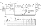
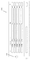
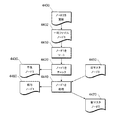
図1は、複数のコンポーネントのデータ系譜100の例を示す。コンポーネントは、論理データセット及び変換を含むことができる。変換は、例えば、データフローグラフ、javaプログラム、コンパイルされた実行可能プログラム、又はそれらの任意の組合せとすることができる。一般に、変換は、入力データを受け入れることができ、出力データを生成することができる。例えば、グラフ1 104は、論理データセット1 102及び論理データセット2 103から入力データを受け入れ、論理データセット2に提供される出力データを生成する。
FIG. 1 shows an example of a
一般に、論理データセットは、データを記憶する1つ又は複数の物理データセットを表す。物理データセットは、日毎に変化し得る一意のデータを含み得る。幾つかの実装形態では、異なるデータを有する物理データセットは、別個のファイルに記憶され得る。例えば、11月8日の外国為替レートデータのデータセットは、ファイル「ExchangeRate_11_08」に記憶し得、11月9日の外国為替レートデータのデータセットは、ファイル「ExchangeRate_11_09」に記憶し得るが、11月8日の為替レートデータのデータセット及び11月9日の為替レートデータのデータセットは両方とも、共通する要素を有する。例えば、両データセットとも、共通のデータフォーマットを共有する。論理データセットは、それらのデータセットの具体的な内容から独立して、物理データセットに対して演算を実行するプログラム又は一連のプログラムを構築できるようにする。 In general, a logical dataset represents one or more physical datasets that store data. The physical dataset may contain unique data that may change from day to day. In some implementations, physical datasets with different data may be stored in separate files. For example, the November 8th foreign exchange rate data dataset can be stored in the file "ExchangeRate_11_08", and the November 9th foreign exchange rate data dataset can be stored in the file "ExchangeRate_11_09". Both the data set for the exchange rate data on the 8th of March and the data set for the exchange rate data on the 9th of November have common elements. For example, both datasets share a common data format. Logical datasets allow you to build a program or set of programs that perform operations on physical datasets, independent of the specific content of those datasets.
一般に、論理データセットについての情報は、データセットに記憶されているデータに伴って変わらないデータセットに起因する情報を含む。例えば、論理データセットについての情報は、フィールド名、データ型、レコードフォーマット、制約、及び他の特徴を含み得る。論理データセットは、データソース及びデータシンクとして分類することができる。単一の論理データセットは、ある変換のデータシンク及び別の変換のデータソースであることができる。論理データセットの対応する物理データセットは、例えば、(場所のなかでも特に)関係データベース内のテーブル又はファイルシステム上のファイルであることができる。データソースは、論理データセットに記憶されているデータレコードを読み出すことができ、インメモリデータレコードを作成することができる。コンポーネントは、データソースにより作成されたインメモリデータレコードを受け入れ、データを変更又は変換する。データ値は変更又は変換することができる。新しいデータレコードを作成することができる。データシンクは、データフローグラフからの出口点を提供することができ、出力レコードを記憶することができる。データソースのように、データシンクは、例えば、関係データベーステーブル又はファイルシステムに記憶されたファイルにアクセスすることができる。コンポーネントは、コンピュータ又は他のタイプのコンピュータデバイスで実行することができる。他の実装形態では、データフローグラフの実行は、複数の計算デバイスに分散することができる。 In general, information about a logical dataset includes information from the dataset that does not change with the data stored in the dataset. For example, information about a logical dataset can include field names, data types, record formats, constraints, and other features. Logical datasets can be categorized as data sources and data sinks. A single logical dataset can be a data sink for one transformation and a data source for another. The corresponding physical dataset of a logical dataset can be, for example, a table in a relational database or a file on a file system (especially in a location). The data source can read the data records stored in the logical dataset and create in-memory data records. The component accepts in-memory data records created by the data source and modifies or transforms the data. Data values can be modified or converted. You can create a new data record. The data sink can provide an exit point from the data flow graph and can store output records. Like a data source, a data sink can access files stored in, for example, relational database tables or file systems. The component can run on a computer or other type of computer device. In other implementations, data flow graph execution can be distributed across multiple computing devices.
幾つかの実装形態では、コンポーネントは、例えば、入力ポートで入力データを受け入れ、例えば、出力ポートで出力データを生成することができる。リンクは、第1のコンポーネントの出力ポートを第2のコンポーネントの入力ポートに接続する。幾つかのコンポーネントは、複数の入力ポート及び出力ポートを有することができる。データレコードを入口点から出口点にナビゲートすることができるコンポーネント及びリンクの順番は、パスと呼ばれる。データ系譜を使用して、異なるパスを識別し、1つ又は複数のコンポーネントを通るデータフローをトレースすることができる。 In some implementations, the component can, for example, accept input data at the input port and generate output data at the output port. The link connects the output port of the first component to the input port of the second component. Some components can have multiple input and output ports. The order of components and links that allow data records to be navigated from entry point to exit point is called a path. Data genealogy can be used to identify different paths and trace the data flow through one or more components.
この例では、データ要素「x」102は、論理データセット1のメンバであり、データ要素「y」103は、論理データセット2のメンバである。一般に、データ要素は、論理データセット内に記憶されている個々のレコードを指す。データ要素は、例えば、論理データセットが関係データベース内のテーブルであることができ、データ要素がそのテーブルからの行であることができる。データ要素「x」及びデータ要素「y」は、グラフ1 140に入力される。グラフ1は論理データセット2 106を生成する。論理データセット2は、データ要素「A」108及びデータ要素「B」110を含む。これらのデータ要素はグラフ2 112に入力される。データ要素「A」は、データ要素「C」114に使用される。データ要素「C」は、入力としてルールセット1 116に提供される。一般に、ルールセットは、出力を生成するためにデータに適用されるルールの集合である。ルールセットは、例えば、データ要素内の値に適用される一連のテスト及び結果であることができる。ルールセットは、1つ又は複数の入力を受け入れ、それらの入力の値に基づいて、1つ又は複数の出力を生成することができる。一般に、ルールセットは、コンパイルされるか、又はコンピュータ実行可能変換にすることができる。図1に示されるデータ系譜グラフ100は、説明を目的として及びスペースを考慮して簡略化されている。一般に、線に沿った省略記号の存在は、1つ又は複数のコンポーネント及びデータソースが省略されたことを示す。示されていないデータ変換を行うこともできる。例えば、データ要素「A」108を変換して、データ要素「C」114を生成してもよい。データ要素「E」118を変換して、データ要素「G」122を生成してもよい等である。
In this example, the data element "x" 102 is a member of the
ルールセット1は、2つの出力データ要素「E」118及びデータ要素「F」120を生成する。データ要素「E」118を使用して、データ要素「G」122を生成する。データ要素「G」は、入力としてルールセット2 130に提供される。ルールセット2は、データ要素「I」132の出力を生成する。データ要素「I」を使用して、論理データセット3 138のデータ要素「J」140を生成する。データ要素「F」120を使用して、データ要素「H」124及びデータ要素「D」126を生成する。データ要素「B」110を使用して、データ要素「M」128を生成する。データ要素「M」128及びデータ要素「D」126は、入力としてルールセット3 134に提供される。ルールセット3は、データ要素「K」136を生成する。データ要素「K」を使用して、論理データセット3 138のデータ要素「L」142を生成する。データ要素「Y」は、入力としてルールセット4 144に提供される。ルールセット4 144は、論理データセット3 138のデータ要素「N」146を生成する。
Rule set 1 produces two output data elements "E" 118 and data element "F" 120. The data element "E" 118 is used to generate the data element "G" 122. The data element "G" is provided as input to rule set 2 130. Rule set 2 produces the output of data element "I" 132. The data element "I" is used to generate the data element "J" 140 of the
論理データセット又はデータ要素に対して行われる変更は、異なるルールセット及びデータ要素に影響し得る。これらの変更は、変更のなかでも特に、スキーマ又はレコードフォーマットへの変更及び異なるデータ要素の有効値への変更を含むことができる。例えば、データ要素のレコードスキーマが変更される(例えば、レコードスキーマは、数値フィールドから文字列フィールドに変更し得る)場合、変更は、そのデータ要素を利用する各ルールセットと、変更されたデータ要素に依存するデータ要素を利用する各ルールセットとに影響し得る。例えば、データ要素Cのレコードフォーマットに対して行われる変更は、ルールセット1、データ要素E、データ要素F、データ要素G、データ要素H、データ要素D、ルールセット2、データ要素I、データ要素J、ルールセット3、データ要素K、及びデータ要素Lに影響し得る。データ要素Xのレコードフォーマットに対して行われる変更は、データ系譜内の他の全ての要素(データ要素Y、ルールセット4、又はデータ要素Nを除く)に影響し得る。 Changes made to logical datasets or data elements can affect different rulesets and data elements. These changes can include, among other things, changes to schema or record formats and changes to valid values for different data elements. For example, if the record schema of a data element changes (for example, the record schema can change from a numeric field to a string field), the change is with each rule set that utilizes that data element and the changed data element. It can affect each ruleset that utilizes data elements that depend on. For example, changes made to the record format of data element C include rule set 1, data element E, data element F, data element G, data element H, data element D, rule set 2, data element I, and data element. It can affect J, rule set 3, data element K, and data element L. Changes made to the record format of data element X can affect all other elements in the data lineage (except data element Y, ruleset 4, or data element N).
システムは、データ要素又はルールセットへの変更の影響についての情報を提供するリポートを生成することができる。例えば、リポート150は、グラフ2上のデータ要素Aに対する変更の影響についての情報を提供する。
The system can generate reports that provide information about the impact of changes on data elements or rulesets. For example,
リポート150は方向列を含む。方向列は、リポートが生成されたデータ系譜の方向を示す。方向は、データ系譜内でそのデータ要素に先行するルールセット、論理データセット、及びデータ要素を指す上流又はデータ系譜内でそのデータ要素に後続するルールセット、論理データセット、及びデータ要素を指す下流のいずれかであることができる。例えば、データ要素Cは、ルールセット1の上流であり、データ要素Aの下流である。
リポート150はグラフ列154も含む。グラフ列は、リポートのセクションの対象であるグラフを識別する。この例では、グラフ2 112がリポートの対象である。リポートは、グラフフィールド列156も含む。グラフフィールド列は、リポートの対象であるフィールドを識別する。一般に、フィールドは、方向が下流の場合、グラフへの入力であり、方向が上流の場合、グラフの出力である。この例では、データ要素A108及びB110がリポートの対象である。
Report 150 also includes
リポート150はルールセットフィールド列158も含む。ルールセットフィールド列は、入力(下流リポートの場合)又は出力(上流リポートの場合)であるデータ要素を識別する。ルールセット列160は、リポートの行の対象であるルールセットを識別する。この例では、リポートは、ルールセット1への入力としてデータ要素Cについての情報を提供し(第1の牽引166において)、ルールセット2への入力としてデータ要素Gについて情報を提供し(2行目168において)、ルールセット2への入力としてデータ要素Hについての情報を提供し(3行目170において)、ルールセット3への入力としてデータ要素Dについての情報を提供し(4行目172において)、ルールセット4への入力としてデータ要素Mについての情報を提供する(5行目において)174。
Report 150 also includes
リポート150は、直列列162及び間接列164も含む。直接列及び間接列は、以下に更に説明するように、コードの分析により特定される。しかし、ここでは、完全性のために提示される。直接列は、ルールセットフィールドにより識別されるデータ要素が、ルールセット内で直接参照される回数を報告する。例えば、直接列は、値を出力に直接割り当てる表現のカウントを含むことができる。間接列164は、ルールセットフィールドにより識別されるデータ要素が、ルールセットフィールドにより識別されるルールセット内の1つ又は複数の他のデータ要素の値に影響する回数を識別する。例えば、間接列は、データ要素の出力値に寄与するルール事例及び他の表現の総数のカウントを表示することができる。ビジネスルールにより計算される出力の場合、表現カウントは、デフォルト値がある場合、デフォルト値を含むルール事例の数である。この例では、データ要素「C」は、ルールセット1において直接13回参照され、1つ又は複数の他のデータ要素の値に70回影響する。
Report 150 also includes
リポート150を生成するために、システムはルールセットを処理して、いずれのデータ要素がルールセットに関連するかを特定する。ルールセットは、例えば、データをあるフォーマットから別のフォーマットに変換するため、データについて判断するため、又は入力データの組に基づいて新しいデータを生成するために使用することができる基準の組として表すことができる。
To generate
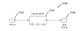
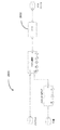
図2は、ルールセット例及びルールセットへの入力を示す。上述したように、ルールセット3 134は2つの入力:データ要素「D」126及びデータ要素「M」128を有する。ルールセット3 134は、「年数」パラメータ202及び「収入」パラメータ204として入力を参照し得る。この例では「年数」パラメータ202及び「収入」パラメータ204は、以下により詳細に説明される変換206により処理される。変換206は「リスク」出力208を生成し、この出力はデータ要素「D」136として提供される。
FIG. 2 shows an example of a rule set and input to the rule set. As mentioned above, rule set 3 134 has two inputs: data element "D" 126 and data element "M" 128. Rule set 3 134 may refer to the inputs as "years"
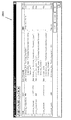
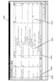
図3は、人間可読ルールセット300の例を示す。人間可読ルールセット300は、グラフィカルユーザインタフェース(GUI)を使用して定義することができるか、又はフラットファイル若しくは他の構造で定義することができる。人間可読ルールセット300は、後述するように、後に変換、例えば、図2の変換206にコンパイルすることができる。例えば、人間可読ルールセット300は、図1のルールセット3 134にコンパイルすることができる。例えば、データ要素Dが収入を表し、データ要素Mが顧客としての年数を表す場合である。再び図3を参照すると、人間可読ルールセット300は表形式で示される。図3に提示される人間可読ルールセット300は、2つの入力302:年数306及び収入308に基づいて、リスクカテゴリ310を出力304として特定するのに使用することができる。この例では、7つの潜在的な条件がある。第1のルール312は、顧客としての年数が15年を超える場合、収入に関係なく、リスクが低いことを述べている。第2のルール314は、顧客が150,000ドルを超える年収を有する場合、顧客である年数に関係なく、最初が低いことを述べている。第3のルール316は、顧客である年数が10年を超え(しかし、15年未満)、60,000ドルを超える収入を有する場合、リスクが低いことを述べている。第4のルール318は、顧客である年数が5年を超える場合、収入に関係なく、リスクが中であることを述べている。第5のルール320は、50,000ドルを超える収入を有する場合、顧客である時間量に関係なく、リスクが中であることを述べている。第6のルール322は、顧客である年数が3年を超え、40,000ドルを超える収入を有する場合、リスクが低いことを述べている。第7のルール324は、その他の場合、リスクが高いことを述べる包括的なルールである。
FIG. 3 shows an example of a human readable rule set 300. The human
なお、この例では、ルールは順次評価される。人物がリスクカテゴリで適格であると、ルール処理は完了する。例えば、人物が顧客である年数が15年を超え、「低」リスクが割り当てられる(行312から)場合、残りの行は決して実行されない。 In this example, the rules are evaluated sequentially. If the person is eligible in the risk category, the rule processing is complete. For example, if a person has been a customer for more than 15 years and is assigned a "low" risk (from row 312), the remaining rows are never executed.
入力フィールド又は出力フィールドのうちの一方への変更の影響を特定するために、システムは、後述するルールセットの分析を実行することができる。 To identify the impact of changes to either the input or output fields, the system can perform an analysis of the ruleset described below.
グラフベースの計算環境でルールセットを実施するために、1つ又は複数のデータソースから入力レコード、例えばデータ要素「C」106を受信し、データ要素、例えば、データ要素「E」118及びデータ要素「F」120を出力データセットに挿入する変換が生成される。入力データセット及び出力データセットは、データストリームと呼ぶこともできる。図1に示されるように、変換は次に、データフローを表す要素をリンクすることにより接続されるデータ処理コンポーネントを有するグラフベースの計算で実施することができる。 To implement a ruleset in a graph-based computing environment, it receives input records from one or more data sources, such as data element "C" 106, and data elements such as data element "E" 118 and data element. A transformation is generated that inserts "F" 120 into the output data set. Input and output datasets can also be referred to as data streams. As shown in FIG. 1, the transformation can then be performed in a graph-based calculation with data processing components connected by linking elements that represent the data flow.
図4は、機械可読コードを含む変換に人間可読ルールセットを変換できるようにするプロセスを示す。ルールセット402、例えば、図3の人間可読ルールセット300は、ルール生成器408に提供される。ルール生成器は、ルールセット402を中間形態にコンパイルする。例えば、ルール生成器406は注釈付きコード408を生成することができる。注釈付きコード408は、ルールへの変更の直接影響及び間接影響を定義する、報告されたメトリック410を含むことができる。例えば、人間可読ルールセット300は、結果として、

等の注釈付きコードを生成することができる。
FIG. 4 shows the process of enabling a human-readable ruleset to be converted into a conversion that includes machine-readable code. The rule set 402, for example, the human readable rule set 300 of FIG. 3, is provided to the
Can generate annotated code such as.
上述したように、直接影響は、ルールセットフィールドにより識別されるデータ要素が、ルールセット内で直接参照されるか、又は設定される回数を記述する。間接影響は、ルールセットフィールドにより識別されるデータ要素が、ルールセット内の1つ又は複数の他のデータ要素の値に影響する回数を識別する。 As mentioned above, the direct effect describes the number of times the data element identified by the ruleset field is directly referenced or set within the ruleset. Indirect effects identify the number of times a data element identified by a ruleset field affects the value of one or more other data elements in the ruleset.
ルール生成器406は、直接メトリック及び間接メトリックを生成することができ、様々な方法で生じうる。例えば、幾つかの実装形態では、ルール生成器406は、ルールセットを分析して、データ要素がアクセスされる各回及び別の値がそのデータ要素に依存する各回を識別することができる。より複雑なシナリオを追跡することもできる。ルール生成器406は、どの程度間接的であるかに関係なく、入力値又は出力値の値に依存するあらゆる変数を追跡することができる。例えば、変数が中間値に影響し、その中間値が最終値に影響する場合、システムは、中間値及び最終値の両方を間接影響として報告することができる。例えば、人間可読ルールセット300は、年数306入力の値にアクセスする4つのルールと、収入308入力の値にアクセスする4つのルールと、リスク310出力の値を設定する7つのルールとを有する。幾つかの実装形態では、ルールセットは、各パラメータの値を少なくとも1回設定すると推測し得る。例えば、年数入力は、入力値がルールセットに提供されるときに設定される。
幾つかの実装形態では、ルール生成器406は、少なくとも部分的にパラメータに依存する、ルールセット内のルール数をカウントすることができる。例えば、人間可読ルールセット300は、年数306入力に依存する7つのルールと、収入308入力に依存する7つのルールと、リスク310出力を設定する7つのルールとを含む。上述したように、ルール324は包括的ルールである。幾つかの実装形態では、包括的ルールは、ルール生成器406により無視し得る。
In some implementations, the
注釈付きコード408は、ルールコンパイラ412に提供することができる。ルールコンパイラ412は、注釈付きコード408を変換206にコンパイルすることができる。一般に、変換は、機械(又は仮想機械)実行可能プログラム、例えば、実行可能プログラム416である。
図4を参照すると、リポート生成器は、データ系譜4の注釈付きコード402に基づいて、リポート408を生成することができる。例えば、再び図1を参照すると、システムは、データ系譜を使用して、例えば、データ要素Xがデータ要素A、B、C、D、E、F、G、H、I、J、K、L、及びMの値に影響することを特定することができる。したがって、グラフ2の処理時、システムは、データ要素Xへの変更がルールセット1、ルールセット2、及びルールセット3に関与することを特定する。しかし、データ要素Xはルールセット4に関与しない。したがって、リポート生成器は、データ要素Xへの変更の影響分析の一環として、ルールセット4を分析する必要がないと判断することができる。
With reference to FIG. 4, the report generator can generate a
図5は、リポート生成器が注釈付きコードに基づいてリポートを生成することを示す。リポート生成器506は、いずれの入力が変更により影響されるかを識別し、影響の計算されたメトリックからの結果を記録する。例えば、データ要素「X」は、ルールセット3への両入力に影響する。したがって、リポート生成器は、メトリック(図4の410)をリポート(図1の行172、174等)に記録する。
FIG. 5 shows that the report generator generates a report based on the annotated code. The report generator 506 identifies which inputs are affected by the change and records the results from the calculated metric of the impact. For example, the data element "X" affects both inputs to rule set 3. Therefore, the report generator records the metric (410 in FIG. 4) in the report (
幾つかの実装形態では、コストを直接計算及び間接計算のそれぞれに関連付けることができる。例えば、直接影響が、プログラマの所定の時間量と、品質保証人員の所定の時間量とを必要とすることを特定することができる。同様に、間接影響が、品質保証人員の所定の時間量を必要とすることを特定することができる。所定の時間、直接影響及び間接影響の計算並びにコンピュータプログラマの時間及び品質保証人員の時間に関連付けられたコストに基づいて、システムは、分析されるシステムに変更を行うことのコスト推定値を提供することができる。 In some implementations, costs can be associated with direct and indirect calculations, respectively. For example, it can be identified that the direct impact requires a predetermined amount of time for the programmer and a predetermined amount of time for the quality assurance personnel. Similarly, it can be identified that the indirect effect requires a predetermined amount of time for quality assurance personnel. Based on the given time, the calculation of direct and indirect effects, and the costs associated with the time of computer programmers and the time of quality assurance personnel, the system provides cost estimates for making changes to the system being analyzed. be able to.
幾つかの実装形態では、ルール生成器を使用して、システム、例えば、図1のデータ系譜100により表されるシステムの異なる部分を識別するに当たり、開発者を支援することができる。
In some implementations, rule generators can be used to assist developers in identifying different parts of the system, eg, the system represented by the
図6は、影響分析技法を使用することができるデータ処理システム600を示す。システム600はデータソース602を含み、データソース602は、それぞれが任意の様々なフォーマット(例えば、データベーステーブル、スプレッドシートファイル、フラットテキストファイル、又はメインフレームにより使用されるネイティブフォーマット)でデータを記憶又は提供することができる、記憶デバイス又はオンラインデータストリームへの接続等のデータの1つ又は複数のソースを含むことができる。実行環境604は、ルール生成器606及びリポート生成器612を含む。実行環境604は、例えば、あるバージョンのUNIXオペレーティングシステム等の適するオペレーティングシステムの制御下で1つ又は複数の汎用コンピュータでホストすることができる。例えば、実行環境604は、ローカルである(例えば、対称マルチ処理(SMP)コンピュータ等のマルチプロセッサシステム)か、ローカルに分散する(例えば、クラスタとして結合される複数のプロセッサ若しくは大規模並列処理(MPP)システムか、リモートであるか、リモートに分散する(例えば、ローカルエリアネットワーク(LAN)及び/又は広域ネットワーク(WAN)を介して結合される複数のプロセッサ)か、又はそれらの任意の組合せの複数の中央演算処理装置(CPU)又はプロセッサコアを使用する構成のコンピュータシステムを含む複数ノード並列計算環境を含むことができる。
FIG. 6 shows a
ルール生成器モジュール606は、ルール仕様をデータソース602から読み出し、ルールの注釈付きコードを記憶する。データソース602を提供する記憶デバイスは、実行環境604にローカルである、例えば、実行環境604をホストするコンピュータに接続される記憶媒体(例えば、ハードドライブ608)に記憶することもでき、又は実行環境604にリモートである、例えば、リモート接続(例えば、クラウド計算基盤により提供される)を介して、実行環境604をホストするコンピュータと通信するリモートシステム(例えば、メインフレーム610)でホストすることもできる。
The
リポート生成器612は、データソース602に記憶することができる、ルール生成器606により生成される注釈付きコード及びデータ系譜を使用して、変更を行うことの影響のリポートを生成する。出力データは、元のデータソース602若しくは実行環境604がアクセス可能なデータ記憶システム616に記憶することができ614、又は別の方法で使用することができる。データ記憶システム616は、開発環境618にもアクセス可能であり、開発環境618において、開発者620は、データ要素、他のプログラミング構造物のルールに変更を行うことの影響を特定することが可能である。開発環境618は、幾つかの実装形態では、頂点間の有向リンク(作業要素、すなわち、データの流れを表す)により接続される頂点(データ処理コンポーネント又はデータセットを表す)を含むデータフローグラフとして、アプリケーションを開発するシステムである。例えば、そのような環境は、Managing Parameters for Graph-Based Applicationsに関してより詳細に記載されている。そのようなグラフベースの計算を実行するシステムについて以下に説明する。このシステムに従って作られるデータフローグラフは、プロセス間で情報を動かし、プロセスの実行順を定義するために、グラフコンポーネントにより表される個々のプロセスに情報を出し入れする方法を提供する。このシステムは、任意の利用可能な方法からプロセス間通信方法(例えば、TCP/IP若しくはUNIXドメインソケットを使用することができるリンクに従った通信パス又は共有メモリを使用して、プロセス間でデータを渡す)を選ぶアルゴリズムを含む。
The
図7は、例示的な影響分析手順700のフローチャートである。プロセスは、図6のデータ処理システム600等のデータ処理システムにより実行することができる。
FIG. 7 is a flowchart of an exemplary
2つのデータセットについての情報が受信される(702)。論理データセット情報は、各論理データセットで、その論理データセット内の少なくとも1つのフィールドの識別子と、そのフィールドについてのフォーマット情報とを識別することができる。 Information about the two datasets is received (702). The logical data set information can identify the identifier of at least one field in the logical data set and the format information about the field in each logical data set.
変換についての情報が受信される(704)。情報は、2つの論理データセットから、変換がデータを受信する第1の論理データセットと、変換されたデータを提供する第2の論理データセットとを識別することができる。変換は、第1の論理データセットからのデータに適用される1つ又は複数のルールについての情報を含み得、1つ又は複数の提案される変更の潜在的な影響を分析することは、1つ又は複数のルールに更に基づく。 Information about the conversion is received (704). The information can identify from the two logical datasets a first logical dataset in which the transformation receives the data and a second logical dataset in which the transformation provides the transformed data. The transformation may include information about one or more rules applied to the data from the first logical data set, and analyzing the potential impact of one or more proposed changes is 1 Further based on one or more rules.
1つ又は複数の提案される変更が受信される(706)。提案される変更は、データセット内のフィールドのフォーマットへの変更、変換への変更、又はルールセットへの変更であることができる。幾つかの実装形態では、提案される変更は、変更の性質を指定せずに、変更される論理データセット内のフィールド又は変換を識別する。例えば、提案される変更は、変更が十進法レコードフォーマットから文字列レコードフォーマットへのものであることを示すことなく、フィールド「X」が変更されることを指定することができる。 One or more proposed changes are received (706). The proposed changes can be changes to the format of the fields in the dataset, changes to conversions, or changes to the ruleset. In some implementations, the proposed change identifies a field or transformation in the logical dataset that is being changed, without specifying the nature of the change. For example, the proposed change can specify that the field "X" is changed without indicating that the change is from a decimal record format to a string record format.
提案される変更が分析される(708)。 The proposed changes are analyzed (708).
提案される変更のメトリックが計算される(710)。メトリックは、変更の影響を測定することができる。メトリックは、直接影響の尺度及び/又は間接影響の尺度を含むことができる。直接影響の尺度の例としては、限定ではなく、変更される入力パラメータがアクセスされるルールセット内のロケーションが挙げられる。間接影響の尺度の例としては、限定ではなく、値が、変更された入力パラメータの値に基づいて設定されるルールセット内のロケーションが挙げられる。 The proposed change metric is calculated (710). Metrics can measure the impact of changes. Metrics can include measures of direct and / or indirect effects. An example of a measure of direct impact is the location in the ruleset where the input parameters that change are accessed, but not limited. An example of an indirect impact scale is a location in a ruleset where a value is set based on the value of a modified input parameter, but not a limitation.
メトリックがソートされる(712)。メトリックは、フラットファイル、関係データベース、又は任意の他の永続的データストアに記憶することができる。メトリックは、リポートの形態で記憶し得る。影響のメトリックを識別するリポートを生成することができる。リポートは、直接影響の尺度及び間接影響の尺度をデータ系譜の特定の部分に関連付けることができる。例えば、リポートは、特定のデータフローグラフ、データフローグラフフィールド、ルールセットフィールド、又はルールセットに直接間接の尺度及び間接影響の尺度が関連付けられることを示すことができる。 The metrics are sorted (712). Metrics can be stored in flat files, relational databases, or any other persistent data store. Metrics can be stored in the form of reports. You can generate a report that identifies the metric of impact. The report can associate a measure of direct and indirect effects with a particular part of the data lineage. For example, a report can indicate that a particular data flow graph, data flow graph field, ruleset field, or ruleset is associated with a direct indirect measure and an indirect impact measure.
幾つかの実装形態では、リポートは、例えば、ハイパーテキスト転送プロトコル(HTTP)リンクを通してデータ系譜に結びつけることができる。リンクを選択又はクリックすることで、ユーザがデータ系譜の特定の部分を見られるようにするアプリケーション又はウェブサイトにクライアントデバイス上のブラウザをナビゲートすることができる。例えば、図1を参照すると、3行目170を選択又はクリックすることで、クライアントデバイス上のブラウザ又は他のアプリケーションにデータフローグラフ「グラフ2」112を表示させることができる。幾つかの実装形態では、その特定のグラフ、グラフフィールド、ルールセットフィールド、及びルールセットは、例えば、強調表示により視覚的に区別することができる。 In some implementations, the report can be tied to a data lineage, for example, through a Hypertext Transfer Protocol (HTTP) link. By selecting or clicking a link, you can navigate the browser on the client device to an application or website that allows the user to see a particular part of the data lineage. For example, referring to FIG. 1, by selecting or clicking 170 on the third line, the data flow graph “Graph 2” 112 can be displayed on the browser or other application on the client device. In some implementations, the particular graph, graph field, ruleset field, and ruleset can be visually distinguished, for example, by highlighting.
幾つかの実装形態では、リポートは、提案される変更に関連付けることができる平均開発及びテストコストを含むことができる。例えば、リポートは、ドルコストを直接変更に関連付け、ドルコストを間接変更に関連付けることができる。幾つかの実装形態では、ドルコストは、プロセスに提供されるパラメータであることができる。他の実装形態では、デフォルト値を各変更に関連付けることができる。例えば、直接変更は、コストを100ドルに決定することができ、間接変更はコストを25ドルに決定することができる。 In some implementations, the report can include average development and testing costs that can be associated with the proposed changes. For example, a report can associate a dollar cost with a direct change and a dollar cost with an indirect change. In some implementations, the dollar cost can be a parameter provided to the process. In other implementations, default values can be associated with each change. For example, a direct change can determine the cost to $ 100 and an indirect change can determine the cost to $ 25.
グラフベースアプリケーションのパラメータ管理
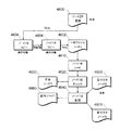
図8Aは、主要素の相互関係を示す本発明の一実施形態のブロック図である。グラフィック開発環境(GDE)802は、実行可能グラフを作成し、グラフコンポーネントのパラメータを定義するユーザインタフェースを提供する。GDEは、例えば、本発明の譲受人から入手可能なCO>OPERATING SYSTEM(登録商標)GDEであり得る。GDE802は、リポジトリ804及び並列オペレーティングシステム806と通信する。リポジトリ804及び並列オペレーティングシステム806には、ウェブインタフェース808及びエグゼクティブ810も結合される。
Parameter Management for Graph-Based Applications FIG. 8A is a block diagram of an embodiment of the present invention showing the interrelationships of the main elements. The Graphic Development Environment (GDE) 802 creates an executable graph and provides a user interface to define the parameters of the graph components. The GDE can be, for example, a CO> OPERATING SYSTEM® GDE available from the assignee of the invention. The
リポジトリ804は、好ましくは、グラフベースアプリケーションの開発及び実行並びにグラフベースアプリケーションと他のシステム(例えば、他のオペレーティングシステム)との間でのメタデータ相互交換をサポートするように設計されたスケーラブルなオブジェクト指向データベースシステムである。リポジトリ804は、ドキュメンテーション、レコードフォーマット、変換関数、グラフ、ジョブ、及び監視情報を含め(しかし、これに限定されない)、全ての種類のメタデータの記憶システムである。リポジトリは当技術分野で既知であり、例えば、米国特許第5,930,794号、同第6,032,158号、同第6,038,558号、及び同第6,044,374号を参照のこと。
並列オペレーティングシステム806は、GDE802において生成されるデータフローグラフの表現を受け入れ、グラフにより定義される処理論理及びリソースに対応するコンピュータ命令を生成する。次に、並列オペレーティングシステム806は通常、それらの命令を複数のプロセッサ(同質である必要はない)で実行する。適する並列オペレーティングシステムは、本発明の譲受人から入手可能なCO>OPERATING SYSTEM(登録商標)である。
The
ウェブインタフェース808は、リポジトリ104の内容のウェブブラウザベースのビューを提供する。ウェブインタフェース808を使用して、ユーザは、オブジェクトを閲覧し、新しいオブジェクトを作成し、既存のオブジェクトを変更し、アプリケーションパラメータを指定し、ジョブをスケジュールするなどを行い得る。ウェブインタフェース808は、グラフのランタイムパラメータについてリポジトリ804に記憶されている情報に基づいて、パラメータ化グラフのフォームベースユーザインタフェースを自動的に作成する。
Web interface 808 provides a web browser-based view of the contents of
エグゼクティブ810は、ウェブインタフェース808を通してアクセスされる任意選択的なリポジトリベースのジョブスケジューリングシステムである。エグゼクティブ810は、ジョブ及びジョブキューをリポジトリ804内のオブジェクトとして維持し、ウェブインタフェース808は、ジョブ及びジョブキューのビューを提供し、それらの操作に役立つ。
図8Bは、入力データセット822がフロー824によりフィルタコンポーネント826に接続された簡略データブローグラフ820を示す。フィルタコンポーネント826は、フロー828により出力データセット830に接続される。データセットは、例えば、グラフフローグラフにより実行される計算のためにデータ(例えば、入力データセット)を提供するか、又はデータ(例えば、出力データセット)を受信するファイル又はデータベーステーブルを含むことができる。
FIG. 8B shows a simplified
データフローグラフ中、「フロー」により表されるデータの流れは、離散データ要素に編成することができる。例えば、要素は、レコード(又は行)及びフィールド(又は列)に編成されたデータセットからのレコードを含むことができる。フィールドシーケンス及びレコード内の値に対応するデータ型を記述するメタデータは、「レコードフォーマット」と呼ばれる。 In a data flow graph, the data flow represented by "flow" can be organized into discrete data elements. For example, an element can include records from a dataset organized into records (or rows) and fields (or columns). The metadata that describes the data types that correspond to the field sequences and the values in the record is called the "record format".
グラフ中のコンポーネント及びデータセットは、フローに接続する入力ポート及び/又は出力ポートを有する。フロー824及び828の「ソースエンド」は、入力データセット822の出力ポート及びフィルタコンポーネント826の出力ポートとそれぞれインタフェースする。フロー824及び828の「シンクエンド」は、フィルタコンポーネント826の入力ポート及び出力データセット830の入力ポートとそれぞれインタフェースする。データセット又はコンポーネントの入力ポート又は出力ポートには、ポートに流れ込むか、又はポートから流れ出るデータのレコードフォーマット等のメタデータが関連付けられる。
The components and datasets in the graph have input and / or output ports that connect to the flow. The “source end” of
ポートのレコードフォーマット又はコンポーネントに関連付けられた他のメタデータを含めパラメータは、パラメータスコーピングのルールに従って値にバインドされる。パラメータは、設計時又は実行時(すなわち、後述する「ランタイムパラメータ」)に値にバインドすることができる。パラメータの値は、例えば、ユーザインタフェースを介してユーザにより定義することもでき(例えば、プロンプトに応答して)、ファイルから定義することもでき、又は同じコンテキスト若しくは異なるコンテキスト内の別のパラメータに関して定義することもできる。例えば、パラメータは、別のパラメータに対して「同じ」関係を有するようにパラメータを指定することにより、異なるコンテキストからエクスポートすることができる(例えば、異なるコンポーネントのコンテキストで評価されたパラメータ)。 Parameters, including the port's record format or other metadata associated with the component, are bound to values according to the rules of parameter scoping. Parameters can be bound to values at design time or at run time (ie, "runtime parameters" described below). Parameter values can be defined by the user, for example, through the user interface (eg, in response to a prompt), from a file, or for different parameters in the same or different contexts. You can also do it. For example, a parameter can be exported from different contexts by specifying the parameter to have a "same" relationship to another parameter (eg, a parameter evaluated in the context of a different component).
グラフで使用されるコンポーネントは、「サブグラフ」を形成するフローと相互接続された他のコンポーネントを使用して実施することができる。サブグラフが、別のグラフでコンポーネントとして使用される前に、コンポーネントの入力ポート及び/又は出力ポート等のそのコンポーネントの様々な特徴が定義される。幾つかの場合、サブグラフコンポーネント間の関係と関係があるコンポーネントの特徴は、そのコンポーネントがグラフで使用される前に指定されるべきである。例えば、サブグラフコンポーネントのランタイムパラメータのプロンプト順を選択する必要があり得る。グラフ中のコンポーネントのランタイムパラメータのプロンプト順を選択する手法について、以下により詳細に説明する。 The components used in the graph can be implemented using other components interconnected with the flows that form the "subgraph". Before a subgraph is used as a component in another graph, various characteristics of that component, such as the component's input and / or output ports, are defined. In some cases, the relationships between subgraph components and the characteristics of the components involved should be specified before the component is used in the graph. For example, you may need to select the prompt order for the runtime parameters of the subgraph component. The method of selecting the prompt order of the runtime parameters of the components in the graph will be described in more detail below.
メタデータ伝搬
レコードフォーマットパラメータ等のポートに関連付けられたメタデータの値は、「伝搬」により得ることができる。メタデータ伝搬は、「外部」又は「内部」で行うことができる。外部メタデータ伝搬の場合、第1のコンポーネントのポートのレコードフォーマットパラメータの値は、フローにより第1のコンポーネントに接続された第2のコンポーネントのポートのレコードフォーマット値を伝搬させることにより、値を得ることができる。値は、フローのソースエンドからシンクエンドに下流に、又はフローのシンクエンドからソースエンドに上流に伝搬することが可能である。メタデータは、定義されたメタデータを有するポートから、定義されたメタデータを有さないポートに伝搬する。
Metadata Propagation The metadata values associated with a port, such as record format parameters, can be obtained by "propagation". Metadata propagation can be done "outside" or "inside". In the case of external metadata propagation, the value of the record format parameter of the port of the first component is obtained by propagating the record format value of the port of the second component connected to the first component by the flow. be able to. The value can propagate downstream from the source end of the flow to the sink end, or upstream from the sink end of the flow to the source end. Metadata propagates from a port that has defined metadata to a port that does not have defined metadata.
内部メタデータ伝搬の場合、コンポーネントのあるポートに定義されたメタデータは、そのコンポーネントを実施するサブグラフに基づいて、そのコンポーネントの別のポートに伝搬する。幾つかの場合、内部メタデータ伝搬は、「非変換」内部データパスを介して行われる。例えば、ユーザは、ソートコンポーネントに流れ込むレコードのデータ型を指定するメタデータをソートコンポーネントの入力ポートに提供し得る。ソートコンポーネントは、レコードを並べ替えるが、変換しないため、データ型はソートコンポーネントにより変更されず、ソートコンポーネントから流れ出るレコードのデータ型を正確に記述するデータ型は、変更されずにソートコンポーネントの出力ポートに伝搬する。 In the case of internal metadata propagation, the metadata defined on one port of a component propagates to another port of that component based on the subgraph that implements that component. In some cases, internal metadata propagation is done through the "unconverted" internal data path. For example, the user may provide metadata to the sort component's input port that specifies the data type of the records that flow into the sort component. The sort component sorts the records, but does not convert them, so the data type is not changed by the sort component, and the data type that accurately describes the data type of the records flowing out of the sort component remains unchanged. Propagate to.
幾つかのコンポーネントは、コンポーネントを通って流れるデータを変換(又は任意選択的に変換)する。例えば、ユーザは、フィルタコンポーネントに流れ込むレコードのフィールドを指定するメタデータをフィルタコンポーネントの入力ポートに提供し得る。フィルタコンポーネントは、各レコードからの所与のフィールドの値を削除し得る。メタデータ定義を使用して、フィルタコンポーネントの出力ポートのメタデータが、コンポーネントのフィルタリング動作に従って入力ポートのメタデータに関連することを指定することができる。例えば、フィルタリングされたフィールドは、レコードフィールドを指定するメタデータから削除され得る。そのようなメタデータ定義は、入力ポートメタデータが分かる前であっても供給することができる。したがって、メタデータは、以下により詳細に説明するように、別のポートのメタデータを含め、ポートに関連付けられたメタデータを1つ又は複数のパラメータの関数として指定できるようにすることにより、変換内部データパスを介してであっても伝搬することができる。 Some components transform (or optionally transform) the data that flows through them. For example, a user may provide metadata to the filter component's input port that specifies the fields of records that flow into the filter component. The filter component may remove the value of a given field from each record. A metadata definition can be used to specify that the output port metadata of a filter component is associated with the input port metadata according to the component's filtering behavior. For example, filtered fields can be removed from the metadata that specifies the record fields. Such metadata definitions can be supplied even before the input port metadata is known. Therefore, metadata is transformed by allowing the metadata associated with a port to be specified as a function of one or more parameters, including metadata for another port, as described in more detail below. It can propagate even through the internal data path.
この内部及び外部メタデータ伝搬は、任意選択的に、グラフが構築中である間、設計時に行うように構成することができ、ユーザは、グラフ中の幾つかのコンポーネントの幾つかのポートにメタデータを供給する。代替的には、メタデータ伝搬は、実行時又は実行時直前を含め、グラフが構築された後に行うことができる。 This internal and external metadata propagation can optionally be configured to be done at design time while the graph is being built, allowing the user to meta to some ports of some components in the graph. Supply data. Alternatively, metadata propagation can be done after the graph has been constructed, including at run time or just before run time.
ランタイムパラメータ
ラインタイムパラメータにより、アプリケーション構築者は、パラメータ値の設定(例えば、ソート関数の主要パラメータ、ファイル名、レコードフォーマット、変換関数等)を実行時(例えば、プログラムが実行されるとき又はコンピュータシステムで間もなく実行されるとき)に延ばすことができる。ランタイムパラメータの値は、エンドユーザにより供給してもよく、又は他のランタイムパラメータの組合せ若しくはオブジェクトリポジトリに記憶されているオブジェクトから導出してもよい。
Runtime Parameters Line-time parameters allow application builders to set parameter values (eg, the main parameters of a sort function, file name, record format, conversion function, etc.) at runtime (eg, when a program is executed or on a computer system). Can be extended to (when it will be executed soon). The values of the run-time parameters may be supplied by the end user, or may be derived from other run-time parameter combinations or objects stored in the object repository.
ランタイムパラメータは、特定量の柔軟性をアプリケーションに追加する。追加の柔軟性は、それらのパラメータをオンデマンドでメタデータ(データフォーマット又はデータ型及びプログラム論理又は変換)の計算に使用することにより達成される。型及び変換は、他の型及び変換、ユーザ供給のパラメータ値、及び記憶されているオブジェクト(例えば、リポジトリから)から合成し得る。これにより、任意のタイプの入力データに対して機能するか、又はランタイムパラメータ値を通して構築が直接又は間接的に制御される一連の変換を通してデータを生成する「汎用」アプリケーションを構築することが可能になる。 Runtime parameters add a certain amount of flexibility to your application. Additional flexibility is achieved by using those parameters in the calculation of metadata (data format or data type and program logic or transformation) on demand. Types and transformations can be synthesized from other types and transformations, user-supplied parameter values, and stored objects (eg, from repositories). This allows you to build "general purpose" applications that work for any type of input data or generate data through a series of transformations whose build is controlled directly or indirectly through run-time parameter values. Become.
幾つかの実装形態では、ランタイムパラメータの作成時又は編集時、開発者は、各パラメータのプロンプト及びプロンプトを表示する条件を指定し得る。システムは、プロンプト指示を解釈して、条件が満たされる場合、パラメータ値を受信するためのグラフィカルユーザインタフェース(GUI)制御機構を提示する。 In some implementations, when creating or editing run-time parameters, the developer may specify prompts for each parameter and the conditions under which the prompts are displayed. The system interprets the prompt instructions and presents a graphical user interface (GUI) control mechanism for receiving parameter values if the conditions are met.
ランタイムパラメータの指定
ランタイムパラメータは、開発者が、グラフ実行時(すなわち、実行時)に外部入力に基づいてグラフの挙動を変更するメカニズムを提供する。好ましい実施形態では、これらの外部値は、直接ユーザ入力により提供される。しかし、これらの外部値は、環境変数及びコマンドラインパラメータを含め、幾つかの異なるソースからのものであってもよい。GDE802は、これらの全ての状況を扱う補正コードを生成すると共に、グラフがGDEから直接実行されるとき、値をテストするように開発者に促す。ランタイムパラメータを使用して、開発者は、例えば、入力ファイルのパスが、特定の名称を有する環境変数により提供されること、次に、環境変数がグラフのインタフェースの既知の部分になることを明示的に宣言することができる。したがって、そのようなパラメータに明確に定義されたインタフェースがある。例えば、生成されたシェルスクリプトを読み出し、環境変数及びコマンドライン引数への参照について検索して、特定のグラフの実行を制御するパラメータセットを見つける必要がない。
Specifying Runtime Parameters Runtime parameters provide a mechanism for developers to change the behavior of a graph at runtime (ie, at runtime) based on external inputs. In a preferred embodiment, these external values are provided directly by user input. However, these external values may come from several different sources, including environment variables and command line parameters. The
図9は、指定されたランタイムパラメータを有するロールアップコンポーネント902及びソートコンポーネント904を有する典型的なグラフ900のブロック図である。ランタイムパラメータ(ソートコンポーネント904のキー及びロールアップコンポーネント902のルール)は、入力のためにインタフェース906においてユーザに提示される。以下のセクションにおいて、ランタイムパラメータをどのように指定し、ユーザ入力を促すランタイムパラメータを提示する統合ユーザインタフェースをどのように作成するかについて説明する。
FIG. 9 is a block diagram of a
ランタイムパラメータは、幾つかの方法で指定又は定義し得る。一方法は、GDE802に表示されるランタイムパラメータグリッドを使用することによるものである。図10は、グラフに関連付けられるランタイムパラメータグリッド1000を表すグラフィカルダイアログの一実施形態の図である。新しいランタイムパラメータは、単に適切なフィールドに入力することにより作成される。各ランタイムパラメータに関連付けられたオブジェクトが、リポジトリ804において作成され、そのパラメータを利用する全てのグラフコンポーネントにリンクされる。例えば、グラフのソートコンポーネントのソートキーがランタイムパラメータとして定義される場合、ソートキーパラメータを表すオブジェクトが、リポジトリ804に記憶され、関連付けられたソートコンポーネントにリンクされる。ランタイムパラメータを定義する代替の方法は、グラフコンポーネントの既存のパラメータを特にフラグ付け、他のコンポーネントから「見える」(他のコンポーネントにエクスポートする)ようにするものである。これらの方法の組合せを使用してもよい。例えば、コンポーネント作成時、開発者は、そのコンポーネントの特定のパラメータをランタイムパラメータとして指定し得る。次に、開発者は、パラメータグリッドを使用して、グラフの全てのランタイムパラメータのデフォルト値及び他の特徴を設定し、新しいランタイムパラメータを定義し得る。
Runtime parameters can be specified or defined in several ways. One method is by using the runtime parameter grid displayed in GDE802. FIG. 10 is a diagram of an embodiment of a graphical dialog representing the
グラフ実行時、パラメータは処理されて、ユーザ入力又は外部プログラムソース(例えば、コマンドラインパラメータ若しくは環境変数)から各パラメータの値を得る。図示の実施形態では、ランタイムパラメータグリッド1000は以下のフィールドを含む。
名称1002 − このフィールドはランタイムパラメータの名称を含む。「Score_threshold」は、名称に示される例である。
型1004 − このフィールドは、ランタイムパラメータで許される値の型を含む。「整数」は型に示される例である。図示の実施形態においてサポートされる型は以下の通りである。
・ブール − 値は真又は偽のいいずれかであることができる、
・選択 − 値は値リストのうちの1つである、
・コレータ − 主要パラメータ値、
・データセット − 外部データファイル及びロケーション、
・日付 − 日付値、
・式 − 算術式、論理式、及び/又は条件式(例えば、select式)、
・フロート − 浮動小数点、
・整数 − 整数、
・レイアウト − 並列又は直列レイアウト定義、
・レコードフォーマット − レコード記述又はレコード記述を含むファイル、
・文字列 − 任意の文字列、
・変換 − 変換記述又は変換記述を含むファイル。
When running the graph, the parameters are processed to get the value of each parameter from user input or an external program source (eg, command line parameters or environment variables). In the illustrated embodiment, the
Name 1002-This field contains the name of the runtime parameter. "Score_threshold" is an example shown in the name.
Type 1004-This field contains the types of values allowed by the run-time parameters. "Integer" is an example shown in the type. The types supported in the illustrated embodiment are:
• Boolean-The value can be either true or false,
• Selection-The value is one of the list of values,
・ Collator − Main parameter value,
Datasets-external data files and locations,
· Date-Date value,
· Expressions-Arithmetic, logical, and / or conditional expressions (eg, select expressions),
Float-floating point,
-Integer-integer,
-Layout-Parallel or serial layout definition,
Record format-a record description or a file containing a record description,
-String-Any string,
• Conversion-A conversion description or a file containing a conversion description.
ロケーション(ロケ)1006 − このフィールドは、レコードフォーマット及び変換型と共に使用される。このフィールドは、型フィールド1004がファイルロケーションを記述するか否か又は型フィールド1004が埋め込み記述を含むか否かを指定する。サポートされるロケーションは以下の通りである
・埋め込み − パラメータはレコード記述又は変換記述を含む、
・ホスト − パラメータは、ホスト機上のファイルへの参照を含む、
・ローカル − パラメータはローカル機上のファイルへの参照を含む、
・リポジトリ − パラメータは、リポジトリ変換又はレコードフォーマットへの参照を含む。
Location 1006-This field is used with record formats and conversion types. This field specifies whether the
• Host-Parameters include references to files on the host machine,
· Local-parameters include references to files on the local machine,
-Repository-Parameters include references to repository conversions or record formats.
デフォルト値1008 − このフィールドは、(1)他の値が外部プログラムソースから提供されない場合に使用される、ランタイムパラメータのデフォルト値又は(2)ユーザ入力からランタイム値をどのように導出するかを記述するルール若しくは式若しくはグラフを実行中のユーザからインタラクティブにその情報を取得する方法を含む。後者の場合、第2のデフォルト値フィールド(図示せず)を使用して、ユーザが入力値を提供しない場合、ランタイムパラメータの値を提供し得る。「ブール」及び「選択」の型では、このフィールドは、ユーザを有効な選択に制限する。「レイアウト」型では、このフィールドは読み取り専用であり、現在定義されているレイアウト定義を表示する。他の全ての型では、このフィールドは、好ましくは、ユーザが有効文字列をタイプし得る単純なテキストエディタである。 Default Value 1008-This field describes (1) the default value of the runtime parameter used when no other value is provided by the external program source, or (2) how to derive the runtime value from user input. Includes a method of interactively retrieving information from a user running a rule or expression or graph. In the latter case, a second default value field (not shown) may be used to provide the value of the runtime parameter if the user does not provide the input value. For "boule" and "selection" types, this field limits the user to valid selections. For the Layout type, this field is read-only and displays the currently defined layout definition. For all other types, this field is preferably a simple text editor where the user can type a valid string.
編集1010 − パラメータ行中の編集スペース1010(又はアイコン、例えば、鉛筆のアイコン)をクリックすると、より高度な編集ウィンドウが開き、このウィンドウは、デフォルト値フィールド1008を編集する様々なオプションをユーザに提示する。図示の実施形態では、以下のエディタが関連付けられた型に利用可能である。
・シングルライン編集 − 整数、フロート、日付、及び文字列型に関するものである、
・選択ダイアログ − ブール及び選択型に関するものである、
・キーエディタ − コレータ型に関するものである、
・ファイルブラウザ − データセット型及びロケーションが埋め込まれていないレコードフォーマット及び変換型に関するものである、
・変換エディタ − 埋め込みロケーションを有する変換型に関するものである、
・レコードフォーマットエディタ − 埋め込みロケーションを有するレコードフォーマット型に関するものである、
・式エディタ − 式型に関するものである、
・レイアウトエディタ − レイアウト型に関するものである。
Edit 1010-Clicking the edit space 1010 (or icon, eg, a pencil icon) in a parameter line opens a more advanced edit window, which gives the user various options to edit the
Single-line editing-for integers, floats, dates, and string types,
• Selection dialog-for Booleans and selection types,
· Key Editor-For collator types,
File Browser-For dataset types and record formats and conversion types with no embedded location,
· Transformation Editor-For transform types with embedded locations,
Record Format Editor-For record format types with embedded locations,
· Expression Editor-For expression types,
-Layout Editor-For layout types.
上記エディタは、種類フィールド値(以下参照)が「PL」(パラメータ言語)である場合を除いて起動する。この場合、ユーザには、グラフ実行時にパラメータ値を導出又はプロンプトするルールを定義するエディタが提示される。 The above editor is started unless the type field value (see below) is "PL" (parameter language). In this case, the user is presented with an editor that defines rules that derive or prompt parameter values when the graph is run.
記述1012 − これは、開発者がランタイムパラメータの予期値を記述する自由形式フィールドである。このフィールドは、デフォルト値が、入力値をユーザに尋ねるルールを含む場合、実行時にプロンプトとして使用される。 Description 1012-This is a free-form field where the developer describes the expected values of the runtime parameters. This field is used as a prompt at run time if the default value contains a rule that asks the user for an input value.
種類1014 − このフィールドは、グラフが、グラフ実行時に、関連付けられたパラメータの値を得る場所を定義する。サポートされる種類フィールド1014値は以下の通りである。
・環境 − ランタイムパラメータの値は、同じ名称の環境変数で見つけられることが予期され、環境変数が定義されない場合、デフォルト値フィールド1008内の値が使用される。パラメータが必要とされ(すなわち、エクスポートパラメータ)、デフォルト値フィールド1008が空である場合、ランタイムエラーが生成され、グラフ実行は停止する、
・位置的 − ランタイムパラメータの値は、アプリケーションを呼び出しているコマンドライン上の相対位置にあることが予期され、例えば、ランタイムパラメータが定義される3番目の位置のランタイムパラメータである場合、そのパラメータ値は、実行スクリプト中の3番目の位置のコマンドライン引数として予期され、指定されるあらゆる位置的パラメータが提供されなければならず、欠けている場合、ランタイムエラーが生成される、
・キーワード − ランタイムパラメータの値はキーワードコマンドラインパラメータとして予期され、図示の実施形態では、キーワードパラメータは、
− <パラメータ名><パラメータ値>
の形態であり、キーワードパラメータは、任意選択的であり、キーワードパラメータが提供されず、デフォルト値フィールド1008が空白であり、対応するエクスポートパラメータが必要とされる場合のみ、ランタイムエラーが生成される、
・固定 − パラメータのランタイム値は常にデフォルト値であり、これは、2つ以上のランタイムパラメータ間で一定の値を共有するのに有用である、
・PL − ランタイムパラメータのデフォルト値は、グラフ実行時、他のパラメータからのランタイムパラメータの値を導出するか、又は追加の入力をユーザに促すものとして解釈されるPL式を含み、本発明の任意の特定の実施形態との併用に選択されるコンポーネント記述言語は、公開されているオブジェクト指向スクリプト言語「Python」等の任意の適するスクリプト言語であり得、そのようなスクリプトは、プログラム制御下でメタデータ(型及び変換)を構築し、条件付きテスト、比較、データ変換、算術演算及び論理演算、文字列及びリスト操作、並びに他の機能をユーザ入力、外部からプログラム的に供給される入力、及び他のランタイムパラメータに対して実行して、任意のランタイムパラメータの最終値を生成する。
Type 1014-This field defines where the graph gets the values of the associated parameters when the graph is run. The supported
• Environment-The value of the runtime parameter is expected to be found in an environment variable with the same name, and if no environment variable is defined, the value in the
Positional-The value of the run-time parameter is expected to be relative to the command line calling the application, for example, if the run-time parameter is the run-time parameter in the third position where it is defined, its parameter value. Must be provided with any positional parameters expected and specified as command line arguments at the third position in the execution script, if missing will generate a runtime error,
The value of the keyword-runtime parameter is expected as a keyword command line parameter, and in the illustrated embodiment, the keyword parameter is
− <Parameter name><Parametervalue>
The keyword parameters are optional, no keyword parameters are provided, the
· Fixed-The parameter runtime value is always the default value, which is useful for sharing a constant value between two or more runtime parameters.
PL-Runtime parameter default values include any of the present invention, including PL expressions that are interpreted as deriving run-time parameter values from other parameters or prompting the user for additional input when running the graph. The component description language chosen for use with certain embodiments of can be any suitable scripting language, such as the publicly available object-oriented scripting language "Python", such scripts being meta under program control. Build data (types and transformations) and perform conditional tests, comparisons, data transformations, arithmetic and logical operations, string and list operations, and other functions as user inputs, externally programmatically supplied inputs, and Run on other run-time parameters to generate final values for any run-time parameters.
図示の実施形態では、ランタイムパラメータグリッド1000で直接作成されたランタイムパラメータを参照する有用な規定は、単にドル符号「$」が先行するパラメータ名を入力することである。例えば、$keyは、keyという名称のランタイム変数を参照する。図示の実施形態では、新しいランタイムパラメータのデフォルトは、「文字列」型及びデフォルトランタイム種類の高度オプションダイアログ中の値に基づくデフォルト種類(デフォルトランタイム種類は「環境」)に設定される。
In the illustrated embodiment, a useful rule to refer to the run-time parameters created directly in the run-
ランタイムパラメータ値は、実行時に決定することができ、PLスクリプトは条件付きテストを提供することができるため、「条件付き」ラインタイムパラメータを作成することができる。条件付きランタイムパラメータは、パラメータの全ての条件 − 実行時に決定される − がイネーブルされている場合のみ、ユーザ入力のプロンプトを生成させる。したがって、例えば、データセットをソートするか否かを求める第1のプロントにユーザが「ノー」で応答する場合、ソートキーを求める第2の条件付きプロンプトは表示する必要がない。 Runtime parameter values can be determined at run time, and PL scripts can provide conditional testing, allowing you to create "conditional" line-time parameters. Conditional run-time parameters generate user-entered prompts only if all of the parameter's conditions-determined at run time-are enabled. Thus, for example, if the user responds "no" to the first prompt asking if the dataset should be sorted, the second conditional prompt asking for the sort key does not need to be displayed.
したがって、設計フェーズ(「設計時間」)中、開発者は、グラフコンポーネントの特定のパラメータを「ランタイム」パラメータとして指定する。次に、そのグラフコンポーネントに関連付けられたオブジェクトは、関連するパラメータデータ(例えば、図9のパラメータグリッド1000からの情報の型)と共に記憶される。
Therefore, during the design phase (“design time”), the developer specifies certain parameters of the graph component as “runtime” parameters. The object associated with that graph component is then stored with the associated parameter data (eg, the type of information from the
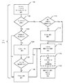
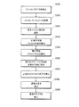
図11は、ランタイムパラメータを使用するプロセスを要約したフローチャートである。実行時中、実行されるアプリケーションに対応するパラメータオブジェクトが検索される(例えば、リポジトリから)(ステップ1100)。そのような各オブジェクトで、ユーザ入力が示されるか否かを判断する(ステップ1102)。示されている場合、プロンプトを表示する任意の条件が満たされているか否かを判断し(ステップ1103)、これは、前のプロンプトへのユーザ入力の評価を含み得る。示されていない場合、デフォルト値が使用される(ステップ1108)。代替的には、パラメータ値は必要ないことができ(例えば、ユーザがソート機能のアクティブ化を選ばなかった場合、ソートキーは必要ない)、したがって無視し得る。その他の場合、ユーザ入力用のプロンプトが生成される(ステップ1104)。 FIG. 11 is a flowchart summarizing the process of using run-time parameters. During runtime, the parameter object corresponding to the application being executed is searched (eg, from the repository) (step 1100). For each such object, it is determined whether or not user input is presented (step 1102). If indicated, determine if any condition for displaying the prompt is met (step 1103), which may include evaluation of user input to the previous prompt. If not indicated, the default value is used (step 1108). Alternatively, the parameter value may not be needed (for example, if the user did not choose to activate the sort function, the sort key is not needed) and can therefore be ignored. Otherwise, a prompt for user input is generated (step 1104).
ユーザが特定のパラメータの値を入力しない場合(ステップ1106)、パラメータのデフォルト値を選択し得る(ステップ1108)。代替的には、エラー状況が生じて、ユーザ入力がないことを示し得る。いずれのイベント(ユーザ入力がないことによるエラー状況がないと仮定して)でも、入力の変換、依存性、及び他のパラメータに基づく条件を考慮して、パラメータの最終値が決定される(ステップ1110)。 If the user does not enter a value for a particular parameter (step 1106), the default value for the parameter may be selected (step 1108). Alternatively, an error situation may occur, indicating that there is no user input. For any event (assuming there is no error situation due to no user input), the final value of the parameter is determined, taking into account input transformations, dependencies, and other parameter-based conditions (steps). 1110).
特定のパラメータへのユーザ入力が示されていないと判断される場合(ステップ1102)、環境変数又はコマンドラインパラメータ等により、パラメータ値を外部からプログラム的に供給するか否かが判断される(ステップ1112)。供給しない場合、パラメータのデフォルト値が選択される(ステップ1114)。代替的には、エラー状況が生じて、指定された型の利用可能な入力がないことを示し得る。いずれの場合(外部入力がないことによるエラー状況がないと仮定して)でも、入力の変換、依存性、及び他のパラメータに基づく条件を考慮して、パラメータの最終値が決定される(ステップ1110)。 When it is determined that the user input to a specific parameter is not shown (step 1102), it is determined whether or not the parameter value is programmatically supplied from the outside by the environment variable or the command line parameter (step 1102). 1112). If not supplied, the default value of the parameter is selected (step 1114). Alternatively, an error situation may occur to indicate that there is no available input of the specified type. In either case (assuming there are no error situations due to the absence of external inputs), the final values of the parameters are determined, taking into account input transformations, dependencies, and other parameter-based conditions (steps). 1110).
最終パラメータ値が決定されると、任意選択的なステップとして、全ての条件付きコンポーネント(後述)は、上述した、指定された条件及びルールに従って、完全に削除するか、又はフロー(すなわち、グラフリンク又はエッジ)で置換することができる(ステップ1116)。使用可能なグラフ構造が最終化され、最終パラメータ値が決定されると、グラフは従来通りに実行される(ステップ1118)。 Once the final parameter value is determined, as an optional step, all conditional components (discussed below) are either permanently deleted or flowed (ie, graph-linked) according to the specified conditions and rules described above. Alternatively, it can be replaced with (step 1116). Once the available graph structure is finalized and the final parameter values are determined, the graph is executed as usual (step 1118).
テスト値
ランタイムパラメータを有するグラフの作成及びテスト中、開発者をサポートするために、GDE802の好ましい実施形態は、ランタイムパラメータのテスト値もサポートする。開発者が、ランタイムパラメータを有するグラフを実行するか、又はグラフコンポーネントに影響している、土台をなすコードを見ることを望む場合、GDE802は、関連付けられたテストパラメータグリッドを表示し、そこで、ユーザは、1つ又は複数のランタイムパラメータの新しいテスト値を入力することができる。好ましくは、最後に使用されたテスト値セットは記憶され、グラフと共に保存される。
Test Values To support developers during the creation and testing of graphs with run-time parameters, a preferred embodiment of GDE802 also supports test values for run-time parameters. If the developer wants to run a graph with run-time parameters or see the underlying code affecting the graph components, the
ランタイムパラメータ毎に、開発者は、所望のテスト値をテスト値列に入力する。編集フィールドを各テスト値列に関連付け得る。テスト値フィールド及び編集フィールドは、パラメータ種類がPLである場合を除き、ランタイムパラメータグリッド900でのデフォルト値フィールド及び編集フィールドと同じように挙動する。
For each run-time parameter, the developer enters the desired test value in the test value sequence. You can associate edit fields with each test value column. The test value field and edit field behave in the same way as the default value field and edit field in the
PL式により、特定のランタイムパラメータの値をユーザに促すことが示される場合、テスト値フィールド及び編集の挙動は、関連付けられたPL式の解釈に基づく。PL式が単に、他の入力に基づいて値を導出する場合、通常モードで、ランタイムパラメータはテスト値グリッドで見えない。 If the PL expression indicates that the user is prompted for the value of a particular run-time parameter, the test value field and editing behavior is based on the interpretation of the associated PL expression. In normal mode, the run-time parameters are not visible in the test value grid if the PL expression simply derives the value based on other inputs.
ランタイムパラメータが値を得る方法を指定
パラメータがランタイムパラメータとして指定された後、対応するオブジェクトがリポジトリ804に作成される。ランタイムパラメータが、値「PL」の種類フィールド914を有する場合、パラメータのデフォルト値フィールド1008は、以下の好ましい形態を有するprompt_for疑似関数を含む。
![]()
![]()
上述したように、prompt_for疑似関数は、前の入力に基づいてプロンプトを表示するか否かを判断する条件式の一部であり得る。 As mentioned above, the prompt_for pseudofunction can be part of a conditional expression that determines whether to prompt based on previous input.
そのようなオブジェクトでは、ユーザインタフェースを使用して、直接入力ランタイムパラメータをユーザに提示する。好ましい実施形態では、ウェブインタフェース808がこの機能を提供する。特に、実行時中、各ランタイムパラメータオブジェクトの各prompt_for疑似関数は、ウェブインタフェース808によりパーズされて、対応するユーザプロンプトを有するウェブページ(例えば、HTMLでの)を生成する。(代替的には、そのようなウェブページは、実行時前に生成し、実行時に単に提示することができる。しかし、そのようなウェブページの実行時生成は、より大きい柔軟性を提供する。特に、ページの内容が前のユーザ入力に依存することができる)。ウェブインタフェース808は、そのようなウェブページを表示し、ユーザ入力を受信することができる従来のウェブブラウザと併せて使用される。 Such objects use the user interface to present direct input run-time parameters to the user. In a preferred embodiment, the web interface 808 provides this functionality. In particular, at runtime, each prompt_for pseudofunction of each runtime parameter object is parsed by web interface 808 to generate a web page (eg, in HTML) with a corresponding user prompt. (Alternatively, such web pages can be generated pre-runtime and simply presented at run time. However, run-time generation of such web pages provides greater flexibility. In particular, the content of the page can depend on previous user input). The web interface 808 is used in conjunction with a conventional web browser capable of displaying such web pages and receiving user input.
prompt_for疑似関数は、パラメータ値を促す方法をウェブインタフェース808に示す。特に、文字列定数であるprompt-kindパラメータは、いずれの種類のユーザインタフェース(UI)要素を提示するかを示す(テキストボックス、ドロップダウンリスト等)。キーワードのカンマ区切りリストである文字列の変更子部分は、様々な種類のプロンプトに共通する幾つかのオプションを提供する。図示の実施形態では、スペースは、変更子文字列内で有意ではない。変更子キーワードは、以下として解釈される。
・in placeというキーワードは、要素がアプリケーションのサマリレベルユーザインタフェースに直接提示されるべきであることを宣言し、より低いレベルまで「掘る」ことなく値を供給できるようにする。in placeが指定されない場合、単純な「編集」ボタンがサマリレベルインタフェースに提示され、そのボタンが、パラメータ値を供給する別のページをユーザに表示する。
・blank okというキーワードは、ユーザが値を供給する必要がないことを宣言し、アプリケーションは、妥当な方法でデフォルト値に対処する。blank okが指定されない場合、ユーザは、何らかの値を供給せずにはアプリケーションを実行することができない。
The prompt_for pseudofunction shows the web interface 808 how to prompt the parameter value. In particular, the prompt-kind parameter, which is a string constant, indicates which type of user interface (UI) element to present (text box, drop-down list, etc.). The string modifier part, which is a comma-separated list of keywords, provides some options common to different types of prompts. In the illustrated embodiment, the space is not significant within the modifier string. The modifier keywords are interpreted as:
The keyword in place declares that the element should be presented directly to the application's summary level user interface, allowing the value to be supplied to lower levels without "digging". If in place is not specified, a simple "edit" button is presented to the summary level interface, which displays to the user another page that supplies the parameter values.
The keyword blank ok declares that the user does not need to supply a value, and the application handles the default value in a reasonable way. If blank ok is not specified, the user will not be able to run the application without supplying some value.
以下は、様々な種類の変更子を有するprompt_for呼び出しの幾つかの例である。
このセクションの残りの部分では、様々なプロンプト種類及びそれに対応するオプションを列挙し、それぞれが、ウェブインタフェース808により生成されるウェブページでどのように見えるかを説明する。
text [size] − 従来のシングルラインテキストボックスsize文字幅を提示する(sizeが供給されない場合、テキストボックスのデフォルトをブラウザのデフォルトサイズに設定する)。
radio choice-list[description-list] − ラジオボタンの組の形態で従来の「1つを選択」プロンプトを提示し、cohice-listの各要素に1つのボタンがある。description-listが供給される場合、各選択は対応する説明でラベルされ、その他の場合、選択は、choice-listからの対応する項目の文字列形態でラベルされる。
radioplus choice-list[description-list] − ラジオのようであるが、テキストボックスの隣に追加のボタンを提示して、ユーザが、choice-listにない「書き込み」値を選べるようにする。
checkbox choice-list[description-list] − チェックボックスの組の形態で従来の「ゼロ以上を選択」プロンプトを提示し、choice-listの各要素に1つのボタンがある。description-listが供給される場合、各選択は対応する説明でラベルされ、その他の場合、選択は、choice-listからの文字列形態の対応する項目でラベルされる。
dropdown choice-list[descritpion-list, size] − choice-listの要素のドロップダウンリストの形態で従来の「1つを選択」プロンプトを提示する。descritpion-listが供給される場合、各選択は対応する説明でラベルされ、その他の場合、選択は、choice-listからの文字列形態の対応する項目でラベルされる。sizeが供給される場合、その多くの選択は一度に可視であり、その他の場合、1つのみが可視である。
multidropdown choice-list[descritpion-list, size] − choice-listの要素のドロップダウンリストの形態で従来の「ゼロ以上を選択」プロンプトを提示する。descritpion-listが供給される場合、各選択は対応する説明でラベルされ、その他の場合、選択は、choice-listからの文字列形態の対応する項目でラベルされる。sizeが供給される場合、その多くの選択は一度に可視であり、その他の場合、ブラウザのデフォルト数の項目が表示される。
key type-obj[size] − 所与のtype-objからのフィールドで構成されるキー(コレータとしても知られる)のプロンプトを提示する。キーは、size部分と同数を有することができ、このデフォルトはtype-obj内のフィールド数に設定される。図12は、キープロンプトにより生成されるグラフィカルダイアログ1200の一実施形態の図である。以下は、3入力キープロンプトのスクリプトテキストの例であり、ここで、ファイル/datasets/fixedは、ドロップダウンボックス1202に示される利用可能なキーの内容を定義する。
${prompt_for“key”, ${dataset_type“/datasets/fixed”},3}
The rest of this section lists the various prompt types and their corresponding options and describes what each looks like in a web page generated by the web interface 808.
text [size] -Present single-line textbox size Presents the character width (if size is not provided, sets the textbox default to the browser default size).
radio choice-list [description-list] -Presents the traditional "choose one" prompt in the form of a set of radio buttons, with one button for each element of the cohice-list. If a description-list is provided, each selection is labeled with a corresponding description, otherwise the selection is labeled in the form of a string of corresponding items from the choice-list.
radioplus choice-list [description-list] -Like a radio, but presents an additional button next to the textbox to allow the user to choose a "write" value that isn't in the choice-list.
checkbox choice-list [description-list] -Presents the traditional "choose zero or more" prompt in the form of a set of checkboxes, with one button for each element of the choice-list. If a description-list is provided, each selection is labeled with a corresponding description, otherwise the selection is labeled with a corresponding item in string form from the choice-list.
dropdown choice-list [descritpion-list, size] -Prepresents the traditional "choose one" prompt in the form of a dropdown list of elements in choice-list. If a descritpion-list is supplied, each selection is labeled with a corresponding description, otherwise the selection is labeled with a corresponding item in the form of a string from the choice-list. If size is supplied, many of the selections are visible at a time, otherwise only one is visible.
multidropdown choice-list [descritpion-list, size] -Prepresents the traditional "choose zero or more" prompt in the form of a drop-down list of elements in choice-list. If a descritpion-list is supplied, each selection is labeled with a corresponding description, otherwise the selection is labeled with a corresponding item in the form of a string from the choice-list. When size is supplied, many of its selections are visible at one time, otherwise the default number of items in the browser is displayed.
key type-obj [size] -Prompts for a key (also known as a collator) consisting of fields from a given type-obj. The key can have the same number as the size part, and this default is set to the number of fields in type-obj. FIG. 12 is a diagram of an embodiment of the
$ {prompt_for “key”, $ {dataset_type “/ datasets / fixed”}, 3}
図示の実施形態では、通常のコレータ順は昇順であるが、ユーザは、関連付けられたチェックボックス1204にチェックを入れることにより、キーの降順コレータ順を選択することができる。
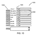
filter tpye-obj − 所与のtype-objの各フィールドへの条件で構成されるフィルタ式のプロンプトを提示する。blank ok変更子はフィルタに影響を有さず、空白フィルタは「真」表現をもたらす。図13は、フィルタプロンプトにより生成されるグラフィカルダイアログ1300の一実施形態の図である。各式のテキスト編集ボックス1304に関連付けられた利用可能なフィールド名1302は、type-objにより定義される。比較値がテキスト編集ボックス1304に入力され、比較演算子(例えば、等しい、より大きい、以下)が、対応するドロップダウンリストコントロール1306から選択される。
flexifilter type-obj − フィルタプロンプトと同様であるが、各ライン上のフィールド名がドロップダウンリストから選択可能な、所与のtype-objの各フィールドへの条件で構成されるフィルタ式のプロンプトを提示する。これにより、複数の条件に対して同じフィールドを使用することが可能である(例えば、フィールドSTATE=MA又はフィールドSTATE=CA)。
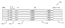
rollup type-obj key[size] − 所与のキーによりロールアップ中の所与のtype-objのフィールドに基づいて、ロールアップ計算のプロンプトを提示する。ロールアップは、sizeルールと同数を有することができ、デフォルトはtype-obj内のフィールド数に設定される。変更子はロールアップに影響を有さず、空白ロールアップは、各グループの主要値のみを提供するパッケージをもたらす。図14は、ロールアッププロンプトにより生成されるグラフィカルダイアログ1400の一実施形態の図である。図示の実施形態では、ドロップダウンボックス1402の列は、利用可能なロールアップ計算関数(例えば、合算、最小、最大)を定義する。各計算に関連付けられる利用可能なフィールド名1404は、type-objにより定義される。各ロールアップルールには、ユーザが所望の式を定義するためのテキスト編集ボックス1406、ソース値が計算に酸化する基準を定義する(ブール式を通して)ための「但し」テキスト編集ボックス1408、及び計算結果を受信するフィールドを指定するための出力フィールドテキスト編集ボックス1410が関連付けられる。明確に導出することができる場合、出力フィールドの名称を指定する必要はない。
reformat type-obj[size] − 所与のtype-objのフィールドに基づいてリフォーマット計算のプロンプトを提示する。リフォーマットはsizeルールと同数を有することができ、デフォルトはtype-obj内のフィールド数に設定される。図15は、リフォーマットプロンプトにより生成されるグラフィカルダイアログ1500の一実施形態の図である。図示の実施形態では、リフォーマットプロンプトは、単に入力フィールドを同様の名称の出力フィールドにコピーするためのセクション1502を含む(チェックボックスコントロールを使用して個々に選択/選択解除されるか、又は全ての選択ボタン又は全て選択せずボタンを使用することによりまとめて)。このプロンプトの第2のセクションは、リフォーマット式を定義する(例えば、total=revenue_1-revenue_2)ことができるテキスト編集ボックス1504の列を含む。各ルールには、リフォーマットの結果を受信するフィールドを指定する出力フィールドテキスト編集ボックス1506が関連付けられる。
outputspec − 出力データセット仕様のプロンプトを提示する。表示されるコントロールは、利用可能なフォーマットオプションを提示するドロップダウンコントロールと、出力データセットの特定のインスタンスの名称を入力するテキスト編集ボックスとを含む。blank ok変更子は、出力データセット仕様に影響を有さない。
fpath starting-point − ファイルパスについてのプロンプトを提示する。プロンプトは基本的にテキストボックスであるが、ファイルパスを閲覧するためのポップアップウィンドウを表示させる「閲覧」ボタンを隣に有する。テキストボックスが非空白である場合、閲覧動作の開始点として使用され、空白の場合、starting-point引数が使用される。
rpath starting-point − リポジトリパスについてのプロンプトを提示する。プロンプトは基本的にテキストボックスであるが、閲覧用のポップアップウィンドウを表示させる「閲覧」ボタンを隣に有する。テキストボックスが非空白である場合、閲覧動作の開始点として使用され、空白の場合、starting-point引数が使用される。
radiofpath choice-list[description-list] − radioplusのようであるが、fpathスタイルボックスプラス閲覧ボタンを「書き込み」スロットに提示する。
radiorpath choice-list[description-list] − radioplusのようであるが、rpathスタイルボックスプラス閲覧ボタンを「書き込み」スロットに提示する。
In the illustrated embodiment, the normal collator order is ascending, but the user can select the descending collator order of the keys by checking the associated
filter tpye-obj-Prompts for a filter expression consisting of conditions for each field of a given type-obj. The blank ok modifier has no effect on the filter, and the blank filter provides a "true" representation. FIG. 13 is a diagram of an embodiment of the
flexifilter type-obj-Similar to the filter prompt, but presents a filter expression prompt consisting of conditions for each field of a given type-obj, with the field name on each line selectable from a drop-down list. do. This allows the same field to be used for multiple conditions (eg, field STATE = MA or field STATE = CA).
rollup type-obj key [size] -Prompts for rollup calculations based on the fields of a given type-obj being rolled up by a given key. The rollup can have the same number as the size rule and defaults to the number of fields in type-obj. The modifier has no effect on the rollup, and a blank rollup results in a package that provides only the key values for each group. FIG. 14 is a diagram of an embodiment of the
reformat type-obj [size] -Prompts for reformatting calculations based on a given type-obj field. Reformatting can have the same number as the size rule and defaults to the number of fields in type-obj. FIG. 15 is a diagram of an embodiment of the
outputspec-Prompts for output dataset specifications. The controls displayed include a drop-down control that presents the available formatting options and a text edit box where you can enter the name of a particular instance of the output dataset. The blank ok modifier has no effect on the output dataset specifications.
fpath starting-point-Prompts for the file path. The prompt is basically a text box, but has a "view" button next to it that displays a pop-up window for viewing the file path. If the text box is non-blank, it will be used as the starting point for the browsing operation, and if it is blank, the starting-point argument will be used.
rpath starting-point − Prompts for the repository path. The prompt is basically a text box, but has a "view" button next to it that displays a pop-up window for viewing. If the text box is non-blank, it will be used as the starting point for the browsing operation, and if it is blank, the starting-point argument will be used.
radiofpath choice-list [description-list] -Like radioplus, but presents the fpath style box plus read button in the "write" slot.
radiorpath choice-list [description-list] -Like radioplus, but presents the rpath stylebox plus read button in the "write" slot.
条件付きコンポーネント
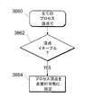
幾つかの実装形態は、パラメータ値及び計算されるメタデータに基づいて、コンポーネントの構造及びグラフの流れに変更を行える条件付きコンポーネントメカニズムを含む。グラフの各コンポーネントは、そのコンポーネントが実行時にグラフに表示されるか否かをコントロールする条件を有する。条件は、直接又はランタイムパラメータを通して間接的に計算することができる。条件付きコンポーネントは、グラフの最適化又は専門化等の様々な目的で使用することができる。最適化の場合、アプリケーションは、特定のデータセットからの値が使用されない場合、それらの特定のデータセットの処理を省くことができ、それにより、グラフをより効率的に実行することができる。専門化の場合、アプリケーションは、所望の詳細レベルに基づいて幾つかの異なる出力データセットの生成を条件付け得るか、又はグラフの幾つかの任意選択的な部分の1つの実行を許可し得る。
Conditional Components Some implementations include conditional component mechanisms that allow changes to the structure of components and the flow of graphs based on parameter values and calculated metadata. Each component of the graph has conditions that control whether that component is displayed on the graph at run time. Conditions can be calculated either directly or indirectly through run-time parameters. Conditional components can be used for a variety of purposes, such as graph optimization or specialization. In the case of optimization, the application can omit the processing of those particular datasets if the values from the particular datasets are not used, which allows the graph to be executed more efficiently. In the case of specialization, the application may condition the generation of several different output datasets based on the desired level of detail, or allow the execution of one of several optional parts of the graph.
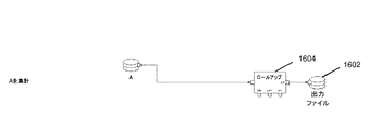
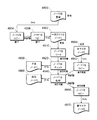
図16Aは、統合結合(MergeJoin)コンポーネント1600がファイルA及びBからのデータを結合し、結果を出力ファイル1602に出力する第1のグラフのブロック図である。図16Bは、ロールアップコンポーネント1604がファイルAからのデータを集計し、結果を出力ファイル1602に出力する第2のグラフのブロック図である。図16Cは、統合結合コンポーネント1606がファイルA及びBからのデータを結合し、ロールアップコンポーネント1608が、生成されたデータを集計し、最終結果を出力ファイル1602に出力するグラフのブロック図である。条件付きコンポーネントを使用して、これらの3つのグラフを結合して、図16Cのグラフのように最初は見えるが、厳密な構造はランタイムまで決定されない単一のグラフにすることができる。適切な条件を設定することにより、ロールアップコンポーネント1608はコネクション(フロー)で置換することができ、図16Aのグラフと同様のランタイムグラフを生成する。同様に、適切な条件を設定することにより、統合結合コンポーネント1606はファイルAへのコネクション(フロー)で置換することができ、図16Bのグラフと同様のランタイムグラフを生成する。
FIG. 16A is a block diagram of a first graph in which the
示される実施形態では、条件付きコンポーネントは、頂点を定義する任意のグラフコンポーネント(すなわち、入力/出力ファイル等のデータセットコンポーネント、リフォーマット若しくはソートコンポーネント等の処理コンポーネント、又はサブグラフとして知られる他のグラフ)であることができる。好ましい実施形態では、条件付きコンポーネントは、2つの特別なパラメータ:条件及び条件解釈により制御される。条件は、評価がランタイムまで延期されるブール式又は値である。示される実施形態では、値「偽」及び「0」は偽条件を指定し、他の全ての値(空を含む)は真条件を示す。条件解釈パラメータは2つの許される相互に排他的な値を有する:完全に削除及びフローで置換。 In the embodiments shown, the conditional component is any graph component that defines the vertices (ie, a dataset component such as an input / output file, a processing component such as a reform or sort component, or another graph known as a subgraph. ) Can be. In a preferred embodiment, the conditional component is controlled by two special parameters: condition and condition interpretation. The condition is a Boolean expression or value whose evaluation is postponed until runtime. In the embodiments shown, the values "false" and "0" specify a false condition, and all other values (including empty) indicate a true condition. Conditional interpretation parameters have two permissible mutually exclusive values: completely delete and replace with flow.
図17は、条件解釈コントロール1704を有する条件1702を提示するグラフィカルダイアログ1700の一実施形態の図である。条件解釈コントロール1704により、完全に削除解釈1706又はフローで置換解釈1708のいずれかを選択することができる。
完全に削除:この解釈を用いる場合、条件が満たされる場合、コンポーネント及びそれに接続されたフロー(すなわち、グラフリンク又はエッジ)は全てグラフから削除される。アクティブな完全に削除条件は機能的に、コンポーネント及びそれに直接接続された全てのフローをグラフから削除する。完全に削除条件は任意のコンポーネントで使用することができる。
FIG. 17 is a diagram of an embodiment of a
Permanently removed: Using this interpretation, if the conditions are met, all components and their connected flows (ie, graph links or edges) will be removed from the graph. The active full delete condition functionally deletes the component and all flows directly connected to it from the graph. The Complete Deletion condition can be used with any component.
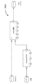
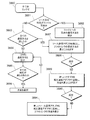
グラフから削除される条件付きコンポーネントは、その条件付きコンポーネントの存在に依存する他の接続されたコンポーネントを「汚染」し、削除させることがある。図18は、そのような汚染が生じる状況を示すグラフ1800の図である。入力ファイルコンポーネント1802への条件が削除を示し、それに対応する条件解釈が完全に削除である場合、入力ファイルコンポーネント1802及びそれに接続されたフローは両方とも、グラフ1800から削除される。次にこれは、ソートコンポーネント1804を汚染し、ソートコンポーネント1804を削除させ、その理由は、ソートコンポーネント1804の入力は必須の入力ポートであるが、ソートコンポーネント1804の入力に接続されているデータフローはもはやないためである。次にこれは、ロールアップコンポーネント1806を汚染し、ロールアップコンポーネント1806を削除させ、その理由は、ロールアップコンポーネント1806の入力は必須の入力ポートであるが、ロールアップコンポーネント1806の入力に接続されているデータフローはもはやないためである。この「消失汚染」を止める唯一のものは、下流コンポーネントの任意選択的又は重要なポートへの接続である。したがって、入力ファイルコンポーネント1802への条件が削除を示す場合、ソート−ロールアップグラフ分岐1808は全体的に、グラフ1800から事実上、削除される。図18における結果は、元のグラフ構造の公称的に3つの入力の結合コンポーネント1810が、実行時に2つの入力の結合コンポーネントになることである。
A conditional component that is removed from the graph can "contaminate" and remove other connected components that depend on the presence of that conditional component. FIG. 18 is a diagram of
一実装形態では、汚染(「黙示条件」としても知られる)の詳細なセマンティクスは以下である。
・コンポーネントが、必須のポートを有し、それに接続されたライブフローがない場合、そのコンポーネント及びそれに接続された全てのフローがグラフから削除される。
・コンポーネントがグラフから完全に削除される場合、そのポートに接続された全てのフローがグラフから削除される。
・コンポーネントがフローで置換される場合、コンポーネントの指定された入力ポート及び指定された出力ポート以外の全てのポートに接続された全てのフローがグラフから削除される。
・必須のインデックス付きポートが、それに接続されたライブフローを有さない場合、同じインデックスを有する対応する任意選択的なインデックス付きポートのそれぞれにつき、その対応するポートに接続されたあらゆるフローがグラフから削除される。
In one implementation, the detailed semantics of pollution (also known as "implied conditions") are:
-If a component has a required port and there is no live flow connected to it, that component and all flows connected to it will be removed from the graph.
-If a component is completely removed from the graph, all flows connected to that port will be removed from the graph.
-When a component is replaced by a flow, all flows connected to all ports except the specified input port and specified output port of the component are deleted from the graph.
· If the required indexed port does not have a live flow connected to it, for each of the corresponding optional indexed ports with the same index, any flow connected to that corresponding port will be shown in the graph. Will be deleted.
これらのルールの驚くべき幾つかの結果がある。例えば、任意選択的なポートのみを有するコンポーネントは、汚染により決して削除することができない。したがって、任意選択的なポートのみを有するコンポーネントは、必要に応じて明示的に削除しなければならない。 There are some surprising consequences of these rules. For example, a component that has only optional ports can never be removed due to contamination. Therefore, components that have only optional ports must be explicitly removed as needed.
図19は、完全に削除条件付きコンポーネントを含むグラフのランタイム準備プロセスを要約したフローチャートである。条件解釈が完全に削除であり、条件が満たされない場合(ステップ1900)、条件付きコンポーネントはグラフから削除されない(ステップ1902)。条件が満たされる場合(ステップ1900)、条件付きコンポーネントは、そのコンポーネントに接続された全てのフローと共にグラフから削除される(ステップ1904)。次に、全ての「汚染された」コンポーネント及びフローは、上述したルールに従ってグラフから削除される(ステップ1906)。 FIG. 19 is a flow chart summarizing the run-time preparation process for a graph that includes fully deleted conditional components. If the conditional interpretation is completely deleted and the condition is not met (step 1900), the conditional component is not removed from the graph (step 1902). If the condition is met (step 1900), the conditional component is removed from the graph along with all the flows connected to that component (step 1904). All "contaminated" components and flows are then removed from the graph according to the rules described above (step 1906).
フローで置換:この解釈を用いる場合、条件が満たされるとき、コンポーネントはフロー(すなわち、グラフエッジ)で置換されるべきである。フローで置換条件解釈は、追加の情報を必要とする。図17を参照すると、ユーザは、コンポーネントがグラフから削除される場合、接続する入力ポート1710(又は必須ポートのファミリ)及び出力ポート1712(又は必須ポートのファミリ)を指定する。デフォルトにより、厳密に1つの所要入力ポート又は必須ポートがあり、厳密に1つの所要出力ポート又は必須ポートがある場合、それらは指定されたフロースルー接続ポート(指定入力ポート及び指定出力ポートとそれぞれ呼ばれる)である。所要ポートは、少なくとも1つのフローを接続する必要があるポートである。 Replace with Flow: Using this interpretation, the component should be replaced with a flow (ie, graph edge) when the condition is met. Permutation condition interpretation in the flow requires additional information. Referring to FIG. 17, the user specifies an input port 1710 (or a family of required ports) and an output port 1712 (or a family of required ports) to connect to when a component is removed from the graph. By default, if there is exactly one required input port or required port and there is exactly one required output port or required port, they are referred to as the designated flow-through connection ports (designated input port and designated output port, respectively). ). A required port is a port to which at least one flow needs to be connected.
図20は、本発明の特定の実施形態でのフローで置換条件付きコンポーネントを含むグラフのランタイム準備プロセスを要約したフローチャートである。示される実施形態での特定の利用可能な入力及び出力への幾つかの依存により(CO>OPERATING SYSTEM(登録商標)で利用可能なコンポーネントに基づく)、幾つかのルールがこの実装形態及びフローで置換条件の使用に適用される。
・条件解釈がフローで置換であり、条件が満たされない場合(ステップ2000)、条件付きコンポーネントはグラフから削除されない(ステップ2002)。
・指定入力ポート及び指定出力ポートを有するコンポーネントは、その指定入力ポートに接続された厳密に1つのライブストレートフローがあり、その指定出力ポートに接続された厳密に1つのライブストレートフローがある場合のみ、フローで置換することができる(「ライブ」フローは、実行時に削除されなかったフローである)(ステップ2004)。そのような場合、コンポーネント自体はグラフから削除され、その指定入力ポートに接続されたストレートライブフロー及びその指定出力ポートに接続されたストレートライブフローは、一緒にリンクされる(ステップ2006)。削除されたコンポーネントの他のポート(すなわち、特定に指定された入力ポート及び出力ポート以外のあらゆるポート)に直接リンクされたあらゆる他のフローは、グラフから削除される。「汚染」された及び削除されたコンポーネントに接続されていたフローはいずれも、上述したように、削除される(ステップ2008)。
・フローで置換条件を有するコンポーネントが、必須入力のファミリ内の2つ以上の指定入力ポートに取り付けられる場合(ステップ2010)、そのコンポーネントは、グラフを有効にするために必要であるため、グラフから削除されない(ステップ2012)。
・所要入力へのライブファンインフローを有するコンポーネントは、特別な取り扱いを必要とする。「ライブファンインフロー」とは、コンポーネントが所要入力ポートに接続されたライブファンイン又はオールツーオールフローを有するか、又はコンポーネントが1つの所要入力ポートに接続された2つ以上のライブストレートフローを有することを意味する。そのようなコンポーネントの場合、フローで置換条件の解釈は、全てのライブ入力フローを収集する収集コンポーネントで条件付きコンポーネントを置換すべきである(ステップ2014)。次に、置換されたコンポーネントに接続されていたあらゆる「汚染」フロー及びコンポーネントは、上述したように削除される(ステップ2016)。
FIG. 20 is a flow chart summarizing the run-time preparation process of a graph containing replacement conditional components in a flow in a particular embodiment of the invention. Due to some dependence on the specific available inputs and outputs in the embodiments shown (based on the components available in CO> OPERATING SYSTEM®), some rules are in this implementation and flow. Applies to the use of substitution conditions.
-If the conditional interpretation is permutation in the flow and the condition is not met (step 2000), the conditional component is not removed from the graph (step 2002).
• Only if a component with a designated input port and a designated output port has exactly one live straight flow connected to that designated input port and exactly one live straight flow connected to that designated output port. , Flows can be replaced (“live” flows are flows that were not deleted at run time) (step 2004). In such a case, the component itself is removed from the graph and the straight live flow connected to its designated input port and the straight live flow connected to its designated output port are linked together (step 2006). Any other flow that is directly linked to any other port of the deleted component (ie, any port other than the specifically specified ingress and egress ports) will be removed from the graph. Any flows connected to the "contaminated" and deleted components will be deleted as described above (step 2008).
• From the graph, if a component with a replacement condition in the flow is attached to two or more designated input ports in the required input family (step 2010), the component is required to enable the graph. Not deleted (step 2012).
• Components with live fan-in flow to the required input require special treatment. A "live fan-in flow" is a live fan-in or all-to-all flow in which a component is connected to a required input port, or two or more live straight flows in which a component is connected to one required input port. Means to have. For such components, the interpretation of the replacement condition in the flow should replace the conditional component in the collection component that collects all live input flows (step 2014). All "contamination" flows and components that were connected to the replaced component are then removed as described above (step 2016).
メタデータ伝搬の態様
グラフのメタデータは、例えば、グラフ開発者、グラフユーザ、又はグラフの別の部分からの伝搬により供給することができる。ポートのレコードフォーマット(例えば、ポートに流入又は流出するレコードのフィールド及びデータ型のシーケンス)、ソート性(sortedness)、圧縮方法、文字セット、バイナリ表現(ビッグエンディアン、スモールエンディアン)、パーテーション、コンポーネントが使用し得る計算リソース(例えば、プロセッサ、一時的なディスク空間)、データ変換、及びコンポーネントが使用し得るメモリ量等のデータ又はデータでの計算に関連付けられたメタデータを含め、様々な種類のメタデータが伝搬可能である。グラフ構築の様々な態様がメタデータの伝搬に影響を及ぼし得る。これらの態様のうちの2つについて以下説明する。
Metadata Propagation Mode Graph metadata can be supplied, for example, by propagation from a graph developer, graph user, or another part of the graph. Used by port record formats (eg, sequences of fields and data types of records entering or leaving the port), sortedness, compression methods, character sets, binary representations (big endian, small endian), partitions, components Various types of metadata, including data such as possible computational resources (eg, processor, temporary disk space), data transformations, and the amount of memory that a component can use, or metadata associated with calculations on the data. Can be propagated. Various aspects of graph construction can affect the propagation of metadata. Two of these aspects will be described below.
コンポーネント削除後の伝搬
幾つかの実装形態では、グラフコンポーネントの削除後にフローが生成される場合、そのようなフロー内のデータを定義するメタデータが、改訂されたグラフ内でどのように伝搬すべきかについて選択しなければならない。メタデータは、フローの一端部から利用可能であり得る。幾つかの実装形態では、フローの上流端部からのメタデータが好ましい。
Propagation after component removal In some implementations, if a flow is generated after the graph component is removed, how should the metadata defining the data in such a flow be propagated within the revised graph? Must be selected for. Metadata may be available from one end of the flow. For some implementations, metadata from the upstream end of the flow is preferred.
フローの上流端部が削除されたコンポーネント(又は収集コンポーネントで置換されたコンポーネント)である場合、GDE802は、削除されていないコンポーネントを見つけるまで、グラフを上流に「歩く」ことによりフローのメタデータを見つける。その上流コンポーネントにより明るみに出たメタデータを使用して、生成されたフローのデータの特徴を定義する。
If the upstream end of the flow is a deleted component (or a component replaced by a collecting component), the
変換されたメタデータの伝搬
上述したように、メタデータは、ポートに関連付けられたメタデータを、別のポートのメタデータを含め、1つ又は複数のパラメータの関数として指定できるようにすることにより、変換中の内部データパスを介してであっても伝搬することができる。例えば、図30Aは、データセット3002及びデータセット3004からのデータに対して結合演算を計算するグラフ3000を示す。この例では、グラフ開発者は、メタデータをデータセットの出力ポートに供給する。次に、メタデータは、入力データセットのレコードに対して結合演算を計算する「スマート結合」コンポーネント3006に伝搬する。例えば、メタデータは、出力ポート3008から入力ポート3010に伝搬する。次に、メタデータは、「スマート結合」コンポーネント3006により変換され、「スマート結合」コンポーネント3006の出力ポート3016からフィルタコンポーネント3018の入力ポート3017に伝搬する。
Propagation of Transformed Metadata As mentioned above, metadata allows you to specify the metadata associated with a port as a function of one or more parameters, including the metadata of another port. , Can be propagated even through the internal data path during conversion. For example, FIG. 30A shows
図30Bは、「スマート結合」コンポーネント3006を実施するサブグラフを示す。コンポーネント3006は、結合コンポーネント3050により実行される結合演算のキーフィールドを表す値を有するkey_fieldパラメータを使用する。コンポーネント3006はまた、条件付きソートコンポーネント3054及び3056を含むための条件として、key_fieldパラメータを使用する。入力ポート3010に流入するレコードが、key_fieldで既にソートされている場合、ソートコンポーネント3054は条件により除外される。同様に、入力ポート3014に流入するレコードが、key_fieldで既にソートされている場合、ソートコンポーネント3056は条件により除外される。入力レコードのいずれかの流れがkey_fieldで依然としてソートされていない場合、ソートコンポーネント3054及び3056は、結合コンポーネント3050に流入する前にレコードをソートする。
FIG. 30B shows a subgraph that implements the "smart join"
この「スマート結合」コンポーネントを通した、変換されたメタデータの伝搬を可能にするために、グラフ開発者は、第1の入力ポート3010のメタデータinput0.metadata、第2の入力ポート3014のメタデータinput1.metadata、及びキーフィールドパラメータkey_fieldの関数として、「スマート結合」コンポーネント3006の出力ポート3016のメタデータ(例えば、フィールドを記述するメタデータ)を定義する。
output.metadata=metadata_join(key_field,input0.metadata,input1.metadata)
To allow the transformed metadata to be propagated through this "smart join" component, the graph developer has asked the metadata input0.metadata for the
output.metadata = metadata_join (key_field, input0.metadata, input1.metadata)
出力ポートメタデータは、関数引数を値にバインド(適切なコンテキストに関して)し、結果に対して関数metadata_joinを実行することにより特定される。この例では、ポート3010及び3014のメタデータは未定義であるため、伝搬したメタデータをメタデータパラメータinput0.metadata及びinput1.metadataにバインドされる。ユーザは、ポート3008から流れるレコードのフィールド「A」及び「B」を指定する出力ポート3008のメタデータを「スマート結合」コンポーネント3006の入力ポート3010に供給する。ユーザはまた、ポート3012から流れるレコードのフィールド「A」及び「C」を指定する出力ポート3012のメタデータを「スマート結合」コンポーネント3306の入力ポート3014に供給する。このユーザ供給のメタデータはポート3010及び3014に伝搬する。結合演算のキーフィールドはフィールドAであり、したがって、「正式パラメータ」key_fieldは値「A」にバインドされる。
Output port metadata is identified by binding function arguments to values (for the appropriate context) and executing the function metadata_join on the results. In this example, the metadata on
関数metadata_joinは、まず、key_fieldパラメータの値が、input0.metadata及びinput1.metadataにより指定されるフィールドの両集合のメンバであるか否かを判断することにより、出力メタデータを特定する。メンバである場合、出力メタデータは2つのフィールドの集合の和集合である。メンバではない場合、出力メタデータは空のフィールド集合を示す。 The function metadata_join first identifies the output metadata by determining whether the value of the key_field parameter is a member of both sets of fields specified by input0.metadata and input1.metadata. If it is a member, the output metadata is the union of a set of two fields. If not a member, the output metadata shows an empty set of fields.
メタデータが「スマート結合」コンポーネント3006の入力ポートに伝搬した(又は別の方法、例えば、ユーザにより供給された)後、「スマート結合」コンポーネント3006の出力ポートの変換されたメタデータは、フィールドA、B、及びCを含む。次に、この変換メタデータは、他のコンポーネントに伝搬することができる。この例では、変換されたメタデータはフィルタコンポーネント3018に伝搬する。
After the metadata has propagated to the input port of the "smart join" component 3006 (or otherwise supplied by the user), the transformed metadata of the output port of the "smart join"
メタデータは、ユーザにより供給されるか、それともポート間を伝搬するかに関係なく、ユーザに表示することができる。例えば、ユーザは、入力デバイス(例えば、マウス)を使用して、メタデータ値を見るコンポーネントの部分を選択することができる。メタデータ伝搬は、そのようなユーザ選択に応答してトリガーすることもできる。 Metadata can be displayed to the user regardless of whether it is supplied by the user or propagated between ports. For example, the user can use an input device (eg, a mouse) to select the part of the component that sees the metadata values. Metadata propagation can also be triggered in response to such user selections.
例示的なメタデータ伝搬プロセス
図31は、例示的なメタデータ伝搬プロセス3100のフローチャートを示す。プロセス3100は、例えば、グラフが変更される都度、ユーザ活動に応答して、及び/又はグラフが実行される直前に実行することができる。プロセス3100は、フローにより決定される部分順序に従って並べられるグラフ内の各コンポーネントを有する作業リスト(例えば、コンポーネントAからコンポーネントBへのフローがある場合、コンポーネントAはコンポーネントBの前に来る)を生成する(3102)。フローが2つのコンポーネント間に一意の順序を決定しない場合、コンポーネントラベルのアルファベット順を同点決着として使用し得る。これは、作業リスト内のコンポーネントに安定した順序を提供する(コンポーネントラベルが一意であると仮定して)。伝搬プロセス3100が、グラフに対して繰り返される(例えば、新しいコンポーネントの追加後)場合、新しい作業リストは、作業リストでの前のコンポーネント間の順序と同じ順序を保持する。
An exemplary Metadata Propagation Process FIG. 31 shows a flow chart of an exemplary
プロセス3100は、作業リストの冒頭から開始され、作業リスト内の各リストについて、プロセス3100は、コンポーネントを実施するサブグラフの仕様(例えば、サブグラフでのデータフロー)に基づいて、コンポーネント内のメタデータを内部伝搬する(例えば、入力ポートから出力ポートに又は出力ポートから入力ポートに)(3104)。この内部メタデータ伝搬は、非変換中のデータパスのいずれかの端部でのポート間で変換されないメタデータの変換を含む。内部メタデータ伝搬は、上述したように、グラフのパラメータ及び/又は他のポートのメタデータを参照するメタデータ定義を有するポートのメタデータを導出することも含む。プロセス3100は、そのようなメタデータ定義に直面する場合、メタデータの導出に値が必要とされるあらゆるパラメータを評価する。
作業リスト上のコンポーネントに対して内部メタデータ伝搬を実行した後、プロセス3100は、メタデータを有するコンポーネントの各ポートからメタデータを有さない関連コンポーネントのポートにメタデータを外部伝搬する(3106)。この外部伝搬によりメタデータを取得するあらゆるコンポーネントは、作業リストの末尾に移動する(3108)。プロセス3100は、作業リストの最後のコンポーネントが処理された後、終了する(3110)。
After performing internal metadata propagation for the components on the work list,
このタイプの外部メタデータ伝搬をサポートするコンポーネント間の一種の関係は、2つのコンポーネントのポート間のデータフローリンク(例えば、入力ポートから出力ポートに又は出力ポートから入力ポートに)である。 A type of relationship between components that supports this type of external metadata propagation is a data flow link between the ports of the two components (eg, from ingress port to out port or from out port to ingress port).
このタイプの外部メタデータ伝搬をサポートするコンポーネント間の別の種類の関係は、あるポートのメタデータが別のポートにも使用し得ることを示すリンクである。このタイプの「メタデータリンク」は必ずしもデータフローリンクに対応するわけではない。例えば、ポートは、特にいかなるポートにも関連付けられていないグラフ中のメタデータへのメタデータリンクを有することができる。 Another type of relationship between components that support this type of external metadata propagation is a link that indicates that metadata on one port can be used on another port. This type of "metadata link" does not necessarily correspond to a data flow link. For example, a port can have a metadata link to metadata in the graph that is not specifically associated with any port.
コンポーネント化サブグラフでのランタイムパラメータ
サブグラフが、別のグラフでのコンポーネントとして使用されるように「コンポーネント化」される前に、コンポーネントの入力ポート及び/又は出力ポート等のコンポーネントの様々な特徴が定義される。ランタイムパラメータを有するコンポーネントを含むサブブラフでは、ランタイムパラメータのプロンプト順を選択すべきである。グラフ中のコンポーネントは必ずしも、順次である必要はないため、ユーザを促すランタイムパラメータの複数の可能な大域的順序が存在することができる。大域的順序の幾つかは、各コンポーネントに関連付けられた元の順序ほど一貫しない。依存性を考慮に入れることが適切な場合には並べ替えながら、各コンポーネント内のパラメータの順序を可能な限り保存した、プロンプトの全域的順序を生成することが有用である。例えば、コンポーネントは、「処理されたデータをどこに記憶したいか?」と尋ねるプロンプトの前に、「いずれのデータを処理したいか?」と尋ねるプロンプトを並べ得る。いずれの順序でもプロンプトを提供することが可能であり得る場合であっても、プロンプトをこの順序で提供することが望ましいことがある。
Runtime Parameters in a Componentization Subgraph Before a subgraph is "componentized" for use as a component in another graph, various characteristics of the component, such as the component's input and / or output ports, are defined. NS. For subbluffs that contain components that have run-time parameters, you should choose the prompt order for the run-time parameters. Since the components in the graph do not necessarily have to be sequential, there can be multiple possible global sequences of run-time parameters that prompt the user. Some of the global orders are not as consistent as the original order associated with each component. It is useful to generate a global order of prompts, preserving the order of the parameters within each component as much as possible, while sorting where it is appropriate to take into account the dependencies. For example, a component may have a prompt asking "Which data do you want to process?" Before a prompt asking "Where do you want to store the processed data?". It may be desirable to provide prompts in this order, even if it may be possible to provide prompts in any order.
プロンプトされるランタイムパラメータを評価するプロセスにおいて、プロンプトされないランタイムパラメータを評価することが必要になることがあるため、プロンプト順は、全てのランタイムパラメータの評価順から得られる。グラフのランタイムパラメータ(いかなるコンポーネントにも関連付けられていないグラフのパラメータを含む)の評価順を決定する一手法は、パラメータ間の依存性を表す1つ又は複数の有向非巡回グラフに基づいて、トポロジソートを実行することを含む。しかし、幾つかのトポロジソートアルゴリズムは、不必要にパラメータを並べ替え得、ランタイムパラメータに望ましくないプロンプト順を生成し得る。 Prompt order is derived from the evaluation order of all run-time parameters, because the process of evaluating prompted run-time parameters may require evaluation of non-prompted run-time parameters. One technique for determining the evaluation order of graph run-time parameters (including graph parameters that are not associated with any component) is based on one or more directed acyclic graphs that represent the dependencies between the parameters. Includes performing a topology sort. However, some topology sorting algorithms can unnecessarily reorder the parameters and generate an undesired prompt order for the run-time parameters.
ソート例1
第1の例では、パラメータソートプロセスは、2つのグラフコンポーネント:コンポーネントI及びコンポーネントIに接続されたコンポーネントIIのパラメータの初期パラメータリストを提供する。この例では、パラメータは、「コンポーネント内」依存性のみを有する。すなわち、コンポーネントのパラメータは、同じコンポーネント内の他のパラメータのみに依存する。パラメータは、以下のように定義される。
Sort example 1
In the first example, the parameter sorting process provides an initial parameter list of the parameters of the two graph components: Component I and Component II connected to Component I. In this example, the parameters have only "intra-component" dependencies. That is, the parameters of a component depend only on other parameters within the same component. The parameters are defined as follows.
コンポーネントIは以下のパラメータを含む。
コンポーネントIIは以下のパラメータを含む。
パラメータが列挙される順序は、値についてユーザを促す所望の順序を定義する。初期パラメータリストは、各コンポーネントにこの「初期順序」を維持する。「序数」が各パラメータに割り当てられて、初期順序でのそのパラメータの場所を示す。以下の表は、この初期順序においてパラメータを列挙する。 The order in which the parameters are listed defines the desired order in which the user is prompted for the values. The initial parameter list maintains this "initial order" for each component. An "ordinal" is assigned to each parameter to indicate the location of that parameter in the initial order. The table below lists the parameters in this initial order.
「依存性」列は、列挙されたパラメータが依存する他のパラメータを示す。依存性は、パラメータの評価に対して順序制約を課す。パラメータは、別のパラメータにより使用される(例えば、参照される)前に定義される必要がある。 The Dependencies column shows the other parameters that the listed parameters depend on. Dependencies impose order constraints on the evaluation of parameters. A parameter needs to be defined before it can be used (eg, referenced) by another parameter.
「共通トポロジソート」アルゴリズムが、リストを通り、各パスで、ゼロ依存性を有するパラメータを順序付き出力リストに転送する。各パス後、転送されたあらゆるパラメータは、依存性列から削除される。このプロセスは、全てのパラメータが転送されるまで繰り返される。出力リスト内のパラメータの順序は、他のパラメータに依存するパラメータが、それらの他のパラメータが評価された後に評価されるような「最終順序」を表す。 A "common topology sort" algorithm passes through the list and, at each path, transfers parameters with zero dependencies to the ordered output list. After each pass, any transferred parameters are removed from the dependency column. This process is repeated until all parameters have been transferred. The order of the parameters in the output list represents the "final order" in which the parameters that depend on the other parameters are evaluated after those other parameters have been evaluated.
この例では、最初のパスにおいて、パラメータx、q、a、及びcが出力リストに転送される。2番目のパスにおいて、パラメータy及びbが出力リストに転送される。3番目の最終パスにおいて、パラメータzが出力リストに転送される。したがって、パラメータの最終順序はx、q、a、c、y、b、zである。この順序はパラメータ依存性により課される順序制約を満たすが、パラメータを不必要に並べ替えない。この例では、初期順序も、パラメータ依存性により課される順序制約を満たす。 In this example, in the first pass, the parameters x, q, a, and c are transferred to the output list. In the second pass, the parameters y and b are transferred to the output list. In the third final pass, the parameter z is transferred to the output list. Therefore, the final order of the parameters is x, q, a, c, y, b, z. This order satisfies the order constraint imposed by the parameter dependency, but does not unnecessarily reorder the parameters. In this example, the initial order also satisfies the order constraint imposed by the parameter dependency.
順序制約を満たすグラフのパラメータの評価順を決定する他の手法は、初期順序を尊重する。例えば、幾つかの手法は、順序制約を満たすようにパラメータを順序づけ、初期順序に基づく基準に従って順序を選ぶ。基準は、順序を初期順序に近いまま保つ(例えば、初期順序への変更に基づくメトリックを最小化する)ことを優先する様々な基準のいずれかを含むことができる。幾つかの場合、複数の順序が基準に従って所与の基準を等しく良好に満たすため、一意の「最良」順序がないことがある。 Other methods of determining the evaluation order of graph parameters that satisfy the order constraint respect the initial order. For example, some techniques order parameters to satisfy order constraints and choose the order according to criteria based on the initial order. Criteria can include any of a variety of criteria that prioritize keeping the order close to the initial order (eg, minimizing metrics based on changes to the initial order). In some cases, there may not be a unique "best" order because multiple orders meet the given criteria equally well according to the criteria.
初期順序を尊重する手法の一例は、「トポロジ変更ソート」手法である。この手法では、初期順序に基づく基準は、いかなる未転送パラメータにも依存しない先行パラメータが転送される前に、初期リストから転送されたパラメータ数を最小化するというものである。換言すれば、「トポロジ変更ソート」は、転送されたパラメータを、ゼロ依存性を有する次のパラメータを転送する前に、依存性列から削除する。上記例では、「トポロジ変更ソート」手法は、初期順序と同じ最終順序x、y、z、q、a、b、cを生成する。 An example of a method that respects the initial order is the "topology change sort" method. In this approach, the criterion based on the initial order is to minimize the number of parameters transferred from the initial list before the preceding parameters, which do not depend on any untransferred parameters, are transferred. In other words, the "topology change sort" removes the transferred parameters from the dependency column before transferring the next parameter with zero dependency. In the above example, the "topology change sort" method produces the same final order x, y, z, q, a, b, c as the initial order.
初期順序を尊重したトポロジ変更ソートプロセス
両方とも各パラメータに割り当てられた序数により決定される初期順序を尊重する、2つの例示的な「トポロジ変更ソート」プロセスの擬似コードを以下に与える。2番目のプロセスは、幾つかの場合、時間効率を改善するような最適化を含む。プロセスは、パラメータについて入力データから生成されるデータ構造を操作する。
Topology Change Sort Process Respecting Initial Order The following is pseudo-code for two exemplary "topology change sort" processes that both respect the initial order determined by the ordinal assigned to each parameter. The second process, in some cases, involves optimizations that improve time efficiency. The process manipulates the data structure generated from the input data for the parameters.
順序付けるN個のパラメータがあると仮定すると、入力データは、一意のパラメータ名、名称付けられたパラメータが依存するパラメータセット(「依存性セット」と呼ばれる)、及び名称付けられたパラメータに関連する情報を記憶する任意選択的な属性データオブジェクトからなるN個の三つ組のリストを含む。 Assuming there are N parameters to order, the input data is associated with a unique parameter name, a parameter set on which the named parameter depends (called a "dependency set"), and a named parameter. Contains a list of N triplets of optional attribute data objects that store information.
この入力データには、「依存性グラフ」と呼ばれるパラメータ間の依存性を表す1つ又は複数の有向非巡回グラフが関連付けられる。一意の各パラメータ名は、依存性グラフ内のノードに対応し、関連付けられた依存性セットは、他のノードからそのノードへのリンクのセットに対応する。したがって、リンクは、第1のパラメータの第1のノードから、第1のパラメータに依存する第2のパラメータの第2のノードを指す。代替的には、リンク方向とパラメータ依存性との対応を逆にすることができる。 This input data is associated with one or more directed acyclic graphs that represent the dependencies between parameters called "dependency graphs". Each unique parameter name corresponds to a node in the dependency graph, and the associated set of dependencies corresponds to a set of links from other nodes to that node. Therefore, the link points from the first node of the first parameter to the second node of the second parameter, which depends on the first parameter. Alternatively, the correspondence between the link direction and the parameter dependency can be reversed.
出力データ構造result_listは、パラメータが、初期順序に近い状態を保つことを優先しながら、別のパラメータの評価に使用される前に評価されるように(必要に応じて)並べ替えられた入力データからのN個のパラメータのリストを含む。出力データ構造result_listを生成するために、プロセスは、パラメータを1度に1つずつ作業データ構造param_listから出力データ構造result_listに転送することにより、パラメータを「なくす」。出力データ構造は、全てのパラメータがなくなった後に完成する。 The output data structure result_list is the input data sorted (if necessary) so that the parameters are evaluated before being used to evaluate another parameter, with priority given to keeping the parameters close to the initial order. Contains a list of N parameters from. To generate the output data structure result_list, the process "eliminates" the parameters by transferring them from the working data structure param_list to the output data structure result_list one at a time. The output data structure is completed after all the parameters are gone.
第1の「トポロジ変更ソート」プロセスは2つのフェーズを含む。第1のフェーズでは、プロセスは、ソートされた出力データ構造に使用するために、入力データに基づいて作業データ構造を構築する。第2のフェーズでは、プロセスは、これらの作業データ構造により表される依存性制約に従って、パラメータを繰り返しソートしてなくす。 The first "topology change sort" process involves two phases. In the first phase, the process builds a working data structure based on the input data for use in the sorted output data structure. In the second phase, the process repeatedly sorts and eliminates the parameters according to the dependency constraints represented by these work data structures.
プロセスが第1のフェーズにおいて構築する作業データ構造の幾つかは、ディクショナリであり、これは、ハッシュ法に基づくデータ構造である。ディクショナリ内の項目には、O(logN)時間で効率的にアクセスすることができる。以下の例示的なデータ構造が、第1のフェーズにおいて構築される。
parm_list[index]:番号インデックスが付与された非消失パラメータ名の順序付きリスト(ここで、インデックス=0はリスト中の最初の項目に対応する)。このデータ構造は「動的」である(すなわち、プロセスの実行中に変化する)。リストは、項目がリストの中央から削除される場合、削除された項目後の項目のインデックスはそれに従ってシフトするように、位置によりインデックス付与される。
n_dependencies_dict[name]:パラメータ名(name)をキーとしたディクショナリであり、エントリは、キーとなるパラメータが依存するパラメータ数を含む。このディクショナリは動的である。
dependers_dict[name]:パラメータ名(name)をキーとしたディクショナリであり、エントリは、キーとなるパラメータに依存するパラメータセットを表すディクショナリ(これもパラメータ名をキーとする)である。このディクショナリは「静的]である(すなわち、プロセスの実行中に変化しない)。
order_doct[name]:パラメータ名(name)をキーとしたディクショナリであり、初期順序でのパラメータの順序位置である0〜N−1の範囲の整数を記憶する。このディクショナリは静的である。
attribute_dict[name]:パラメータ名(name)をキーとしたディクショナリであり、キーとなるパラメータの任意選択的な属性データオブジェクトを記憶する。このディクショナリは静的である。
result_list[index]:番号インデックスが付与されたプロセスの出力を表すパラメータ名及び属性の順序付きリストである(ここで、インデックス=0はリスト中の最初の項目に対応する)。このデータ構造は最初空である。このデータ構造は動的である。
Some of the working data structures that a process builds in the first phase are dictionaries, which are hash-based data structures. Items in the dictionary can be efficiently accessed in O (logN) time. The following exemplary data structure is constructed in the first phase.
parm_list [index]: An ordered list of non-disappearing parameter names with number indexes (where index = 0 corresponds to the first item in the list). This data structure is "dynamic" (ie, it changes during the execution of the process). The list is indexed by position so that if an item is removed from the center of the list, the index of the item after the deleted item shifts accordingly.
n_dependencies_dict [name]: A dictionary with the parameter name (name) as the key, and the entry contains the number of parameters that the key parameter depends on. This dictionary is dynamic.
dependers_dict [name]: A dictionary with the parameter name (name) as the key, and an entry is a dictionary (also with the parameter name as the key) that represents a parameter set that depends on the key parameters. This dictionary is "static" (that is, it does not change during the execution of the process).
order_doct [name]: A dictionary using the parameter name (name) as a key, and stores an integer in the range of 0 to N-1, which is the order position of the parameters in the initial order. This dictionary is static.
attribute_dict [name]: A dictionary with the parameter name (name) as the key, and stores the optional attribute data object of the key parameter. This dictionary is static.
result_list [index]: An ordered list of parameter names and attributes that represent the output of the numbered process (where index = 0 corresponds to the first item in the list). This data structure is initially empty. This data structure is dynamic.
プロセスの時間効率を分析するために、依存性グラフの平均「度」(又はノードからのリンク数)がzであると仮定する。これらのデータ構造の構築には、O(N*z)時間がかかるn_dependencies_dict及びdependers_dictを除き、O(N)時間がかかる。 To analyze the time efficiency of the process, we assume that the average "degree" (or number of links from the nodes) of the dependency graph is z. Construction of these data structures takes O (N) time, except for n_dependencies_dict and dependers_dict, which take O (N * z) time.
第2のフェーズにおいて、プロセスは、まず、依存する非消失パラメータの数により(すなわち、パラメータのn_dependencies_dictの値により)最低から最高にパラメータを順序付け、次に、パラメータの順序により(すなわち、order_dictの値により)最低から最高に順序付けるソート基準by_n_deps_and_orderに従って、param_listデータ構造内のパラメータをソートする。次に、プロセスは、ソートされたparam_listにおいて最初のパラメータを消す。このパラメータのn_dependencies_dictの値はゼロであるべきである。(ソートされたparam_list中の最初のパラメータのn_dependencies_dictの値がゼロではない場合、エラーがフラグ付けられる)。 In the second phase, the process first orders the parameters from lowest to highest by the number of non-disappearing parameters they depend on (ie, by the value of the parameter's n_dependencies_dict), and then by the order of the parameters (ie, the value of order_dict). Sorts the parameters in the param_list data structure according to the sorting criteria by_n_deps_and_order, which orders from lowest to highest. The process then deletes the first parameter in the sorted param_list. The value of n_dependencies_dict for this parameter should be zero. (If the value of n_dependencies_dict for the first parameter in the sorted param_list is non-zero, an error is flagged).
パラメータを消すために、プロセスは、パラメータをresult_list(対応するあらゆる属性と共に)に添付し、そのパラメータに依存する全てのパラメータ(すなわち、dependers_dict中のパラメータ)の依存性カウント(すなわち、n_dependencies_dictの値)を1だけデクリメントする。最後に、パラメータはparm_listから削除される。結果として最初になるパラメータのこのソート及び消失は、全てのパラメータがなくなるまで繰り返される。 To eliminate a parameter, the process attaches the parameter to result_list (with any corresponding attributes) and the dependency count (ie, the value of n_dependencies_dict) for all parameters that depend on that parameter (ie, the parameters in dependers_dict). Decrement only 1. Finally, the parameter is removed from parm_list. This sorting and disappearance of the resulting first parameter is repeated until all parameters are exhausted.
以下は、消失手順の疑似コード定義である。
消失手順の引数はリスト(値は、例えば、param_listである)及びインデックスである。関数result_list.appendは、位置インデックスにおいて示されたリスト項目をそれに関連付けられた属性と共にresult_listに添付する。次に、手順は、消失したパラメータをキーとしたdependers_dictデータ構造のメンバである、消失したパラメータに依存する各パラメータのn_dependencies_dictの値をデクリメントする。次に、手順は、listからそのパラメータを削除する。消失手順の実行時間はO(zlogN)である。 The arguments of the disappearance procedure are a list (value is, for example, param_list) and an index. The function result_list.append attaches the list item indicated in the position index to result_list along with its associated attributes. The procedure then decrements the value of n_dependencies_dict for each parameter that depends on the lost parameter, which is a member of the dependers_dict data structure with the lost parameter as the key. The procedure then removes that parameter from the list. The execution time of the disappearance procedure is O (zlogN).
以下は、第1の「トポロジ変更ソート」プロセスのソート/消失ループの疑似コードである。
プロセスはまず、上述したソート基準by_n_deps_and_orderに従ってparam_listのパラメータを順序付ける関数parm_list.sort(by_n_deps_and_order)を使用して、param_listの初期ソートを実行する。次に、プロセスは消失手順を実行し、その後、param_listが空になるまで、param_listの別のソートを実行する。プロセスは、param_list内の最初のパラメータ(インデックス=0を有する)への依存数がゼロになることを確実にするためにチェックする。ゼロではない場合、プロセスはそのパラメータを削除し、循環エラーを記録し、継続する。ソートはO(N\logN)かかり、ループ範囲はNであり、したがって、ループの全体実行時間の推定はO(N2logN)である。 The process first performs an initial sort of param_list using the function parm_list.sort (by_n_deps_and_order), which orders the parameters of param_list according to the sort criteria by_n_deps_and_order described above. The process then performs the disappearance procedure and then another sort of param_list until the param_list is empty. The process checks to ensure that the number of dependencies on the first parameter (having index = 0) in param_list is zero. If non-zero, the process removes the parameter, records a circular error, and continues. The sort takes O (N \ logN) and the loop range is N, so the estimate of the total execution time of the loop is O (N2logN).
第2の「トポロジ変更ソート」プロセスは、z<<Nであるように依存性グラフが疎である場合を利用する。1回の初期ソート後、プロセスは、いかなる他のパラメータにも依存しないパラメータのリスト候補のソート性を維持することができる。これは、この予期される実行時間を後述するように短縮する。 The second "topology change sort" process utilizes the case where the dependency graph is sparse, such as z << N. After one initial sort, the process can maintain the sortability of the parameter list candidates, which is independent of any other parameters. This reduces this expected execution time as described below.
以下は、第2の「トポロジ変更ソート」プロセスの疑似コードである。
プロセスはまず、上述したソート基準by_n_deps_and_orderに従って、param_listのパラメータを順序付ける関数parm_list.sort(by_n_deps_and_order)を使用して、param_listの初期ソートを実行する。次に、プロセスは、3つのセクション(「#section 1」、「#section 2」、及び「#section 3」と記される)を有するループを実行する。
The process first performs an initial sort of param_list using the function parm_list.sort (by_n_deps_and_order), which orders the parameters of param_list according to the sort criteria by_n_deps_and_order described above. The process then executes a loop with three sections (denoted as "
セクション1において、プロセスは、ゼロ依存性を有するパラメータのみを含む候補リストを構築する。プロセスは、parm_list中の全てのパラメータをスキャンし、それらを候補に添付し、相対順序を保存する。
In
セクション2において、プロセスは、候補からのパラメータがなくなり、新しいパラメータが候補に統合されるループを実行する。this_parmとして保存される候補中の第1のパラメータは、候補からなくなり、param_listから削除される。関数get_new(this_parm)は、新たに消えたthis_parmでのdependers_dictのメンバであり、ゼロ依存性のままであるパラメータの名称のリストを返す。次に、最後の依存性がなくなったパラメータを表すこれらのパラメータは、by_n_deps_and_orderに従ってソートされ(それぞれの序数に従って並べられることを保証するために)、候補に統合される。したがって、候補リストは、序数によりソートされたゼロ依存性パラメータのリストのままである。 In Section 2, the process runs a loop in which the parameters from the candidates are removed and the new parameters are integrated into the candidates. The first parameter in the candidates saved as this_parm is no longer a candidate and is removed from the param_list. The function get_new (this_parm) is a member of the newly disappeared dependsers_dict in this_parm and returns a list of the names of the parameters that remain zero dependent. These parameters, which represent the last parameters that are no longer dependent, are then sorted according to by_n_deps_and_order (to ensure that they are ordered according to their ordinal numbers) and integrated into the candidates. Therefore, the candidate list remains a list of zero-dependent parameters sorted by ordinal.
例えば、2つのパラメータが互いに関して定義される場合に生じる「循環エラー」がある場合のみ、セクション3に入る。この場合、プロセスは、parm_listを再びソートし、parm_list中の最初のパラメータは、非ゼロ依存性を有する場合、削除され、ループはセクション1から繰り返される。
For example,
循環エラーがないと仮定すると、Nパラメータリストであるparm_listは、最初のみソートされ、その結果、ソート時間はO(NlogN)である。その後、ソートは、候補リストの最上部にあるパラメータをなくした結果生成される、新たに生成されるゼロ依存性パラメータのはるかに小さいリストに対してのみ行われる。このリストのサイズはz未満であり(平均で)、その結果、ソート時間はO(zlogz)であり、統合時間はO(z)である。したがって、ループの一反復はO(zlogz)であり、総時間はO(Nzlogz+NlogN)である。zがNの増大に伴って増大しない場合、この時間は事実上、O(NlogN)である。 Assuming no circular error, the N parameter list parm_list is sorted only at the beginning, resulting in a sort time of O (NlogN). Sorting is then performed only on the much smaller list of newly generated zero-dependent parameters that result from the removal of the parameters at the top of the candidate list. The size of this list is less than z (on average), so that the sort time is O (zlogz) and the integration time is O (z). Therefore, one iteration of the loop is O (zlogz) and the total time is O (Nzlogz + NlogN). If z does not increase with increasing N, then this time is effectively O (NlogN).
ソート例2
別の例では、パラメータソートプロセス(例えば、第1又は第2の「トポロジ変更ソート」プロセス)は、図32Aに示されるように、グラフコンポーネント3202、3204、及び3206を有するグラフ3200のランタイムパラメータの初期リストを決定する。グラフ3200は、入力データセット3210の出力ポート3208及び出力データセット3214の入力ポート3212に関連付けられたランタイムパラメータも有する。この例では、パラメータは、「コンポーネント内」依存性及び「コンポーネント間」依存性の両方を有する。すなわち、コンポーネントのパラメータは、同じコンポーネント内のパラメータに依存すると共に、他のコンポーネント内のパラメータに依存する。この例では、コンポーネント間依存性は、幾つかのパラメータが依存するメタデータの伝搬を可能にするコンポーネント間のフローに起因して生じる。
Sort example 2
In another example, the parameter sorting process (eg, the first or second "topology change sorting" process) is the run-time parameters of
依存性は、図32Aにおいて、第1のパラメータ又はポートから第2のパラメータ又はポートへの点線矢印で示される。ポートへの矢印は、リンクされたパラメータの値がそのポートから下流ポートに伝搬することを示す。ポートからの矢印は、値が上流ポートからリンクされたパラメータに伝搬することを示す。第1のパラメータから第2のパラメータへの矢印は、第2のパラメータの値が第1のパラメータの値に依存(例えば、参照)することを示す。 Dependencies are indicated in FIG. 32A by a dotted arrow from the first parameter or port to the second parameter or port. An arrow to a port indicates that the value of the linked parameter propagates from that port to the downstream port. Arrows from the port indicate that the value propagates from the upstream port to the linked parameter. The arrow from the first parameter to the second parameter indicates that the value of the second parameter depends on (eg, see) the value of the first parameter.
図32Bは、グラフ3200に基づくパラメータp0、p1、p2、p4、p5、及びp6間の順序制約を表す依存性グラフ3250を示す。図32Cは、グラフ3200に基づくパラメータp3、p7、p8、及びp9間の順序制約を表す依存性グラフ3252を示す。
FIG. 32B shows a
パラメータソートプロセスは、グラフ3200での要素の配置の順序に従って、様々なグラフ要素の10個のパラメータp0、p2、...、p9のそれぞれに序数を割り当てる。図32Aでは、グラフ3200に追加される(例えば、GDE802を使用してユーザにより)最初のグラフ要素は、パラメータp0、p1、及びp2を有するコンポーネント3202である。追加される2番目の要素は、パラメータp3、p4、及びp5を有するコンポーネント3206である。追加される3番目の要素は、パラメータp6を有するデータセット3210である。追加される4番目の要素は、パラメータp7を有するデータセット3214である。追加される最後の要素は、ランタイムパラメータを有さないデータセット3216である。以下の表は、割り当てられた序数により定義される初期順序でパラメータを列挙する。
The parameter sorting process follows the order of arrangement of the elements in
様々な処理段階でのparam_list及びresult_list中のパラメータの以下のリストは、上述した第1の「トポロジ変更ソート」プロセスに対応する。param_listは、各段階においてソート基準by_n_deps_and_orderに従ってソートされて示される。
様々な処理段階での候補及びresult_list中のパラメータの以下のリストは、上述した第2の「トポロジ変更ソート」プロセスに対応する。パラメータは各段階で同じ順序のままであるため、段階間で候補をソートする必要はない。
したがって、図33を参照すると、「トポロジ変更ソート」プロセス3300は、入力として、ランタイムパラメータの値をユーザに促すための所望の第1の順序3302及びパラメータの順序制約3304(例えば、依存性グラフ3350及び3352)をとる。プロセス3300は、所望の第1の順序3302に従って順序制約を満たすパラメータセットの新しい順序3306を提供する。
Therefore, referring to FIG. 33, the "topology change sort"
典型的な使用
通常、ユーザは、ウェブインタフェース808の前に座り、リポジトリ104において、実行しようとするアプリケーションのグラフを見つける。アプリケーショングラフに関連付けられた全てのオブジェクトをスキャンすることにより、ウェブインタフェース808は、ユーザがアプリケーションのランタイムパラメータの値を指定することができるウェブページフォームを生成する。全てのランタイムパラメータが指定されると、アプリケーションとパラメータ設定との組合せはジョブとして一緒にされ、エグゼクティブ810による実行にスケジュールされる。ジョブを実行するとき、エグゼクティブ810は、既知の方式での並列オペレーティングシステム806の下における実行のためにアプリケーションをキューに入れる。並列オペレーティングシステム806は、追跡情報及びジョブステータスを収集し、この情報をリポジトリ804に記憶し、それにより、ユーザ及び管理者は、ジョブの進行及び実行を追跡することができる。
Typical Use Typically, the user sits in front of the web interface 808 and finds a graph of the application to run in the
例
図21は、ランタイムパラメータがないロールアップアプリケーションを表すグラフ2100の図である。このグラフは、各種のアカウント数を計算し、結果を出力ファイルに書き込む。このアプリケーションのあらゆる態様は、グラフを作成した開発者によって決定されている:入力ファイルコンポーネント2102の名称、入力データのフォーマット、ハッシュロールアップコンポーネント2104でのデータのロールアップに使用されるキー及び変換ルール、出力フォーマット、並びに出力ファイルコンポーネント2106の名称。ユーザは、厳密に定義されたようにこのグラフを実行することのみ可能である。
Example FIG. 21 is a diagram of
図22は、図21のロールアップアプリケーションのランタイムパラメータ化バージョンを表すグラフ2200の図である。このアプリケーションのデータフローグラフ構造は、非ランタイムパラメータ化バージョンにかなり類似するが、アプリケーションははるかに柔軟である。ランタイムパラメータを通して、エンドユーザは、抽象入力データセット2202(入力ファイル名及びフォーマットが導出される保存オブジェクト)の名称、ハッシュロールアップコンポーネント2204のロールアップキー及びロールアップルール、並びに出力ファイルコンポーネント2206の名称を指定し得る。
FIG. 22 is a diagram of
図23は、図22のアプリケーション例のランタイムパラメータグリッド2300を表すグラフィカルダイアログの一実施形態の図である。これは、図9に示されるパラメータグリッドの入力済みバージョンである。なお、デフォルトパラメータの数は、上述したように、prompt_for疑似関数を使用して定義され、したがって、ウェブインタフェース808を通したユーザ入力を必要とする。このグラフの外観は、非ランタイムパラメータ化アプリケーショングラフと殆ど変わらないが、1つ又は複数のパラメータグリッド(又は他の適するコントロール)により、開発者は、グラフの実行を制御する全てのパラメータを完全に追跡することができる。
FIG. 23 is a diagram of an embodiment of a graphical dialog representing the
図24Aは、図23のパラメータグリッド2300内の情報からウェブインタフェース808により生成されるフォーム2400を表すグラフィカルダイアログの一実施形態の図である。この例では、フォーム2400は、ユーザ入力の4つのランタイムパラメータを提示する:入力データセットリポジトリパス2402、ロールアップキー2404、ロールアップルール2406、及び出力パス2408。図17Bは、ユーザがパラメータ値を入力した図24Aのフォーム2400の図である。直接入力及び/又はランタイムパラメータ2402〜2408に関連付けられた編集又はブラウザ制御ボタンを使用して、ユーザは、関連付けられたグラフを実行するための対応するパラメータ値2410〜2416を提供する。
FIG. 24A is a diagram of an embodiment of a graphical
図25は、ランタイムパラメータ化ロールアップ及び結合アプリケーションを表すグラフ2500の図である。図26は、図25のアプリケーション例のランタイムパラメータグリッド2600を表すグラフィカルダイアログの一実施形態の図である。ここで、アプリケーションの幾つかの態様はパラメータ化されているが、結合キー及び入力データセットを含め、大半は固定されたままである。図27は、図26のパラメータグリッド2600内の情報からウェブインタフェース808により生成されるフォーム2700を表すグラフィカルダイアログの一実施形態の図である。なお、ロールアップへの入力タイプは、トップレベルフォームが表示されるときには分かっているため、ロールアップルール2702は現場でプロンプトすることができる。
FIG. 25 is a diagram of
図28は、ランタイムパラメータ化ロールアップ−結合−ソートアプリケーションを表すグラフ2800の図である。図25の例と同様であるが、条件付きソートコンポーネント2802がグラフ2800に追加されている。図29は、図28に示されるアプリケーション例のランタイムパラメータ化グリッド2900を表すグラフィカルダイアログの一実施形態の図である。sort_keyランタイムパラメータ2902は、ソートが望ましいことをユーザが示す場合のみ、プロンプトされる。この効果を得るために、開発は、sort_keyランタイムパラメータ2902のデフォルト値2904のif条件付きテスト内にprompt_for疑似関数を配置する。if条件付きテストは、第2のランタイムパラメータdo_sort2906を参照する。do_sortパラメータ2906のデフォルト値フィールド2908及び説明フィールド2910は、テキストプロンプト「データをソートすべきか?」に対する真/偽又はイエス/ノーの答えについてユーザに尋ねるラジオプロンプトを生成するために定義される。do_sortパラメータ2906に提供された値が「真」である場合、ソートコンポーネント2802は、実行時にグラフの一部として含まれることになる。その他の場合、ソートコンポーネント2802は、指定された条件解釈に応じて、グラフから完全に削除されるか、又はフローで置換されることになる。
FIG. 28 is a diagram of
スクリプト実施
GDE802は、パラメータ化グラフの構築に役立つが、フォームベースのインタフェースを提供しようとする非グラフプログラムがあることがある。アプリケーションレベルPL及びリポジトリ804を使用して、任意のシェルスクリプトをパラメータ化することができる。例えば、アプリケーションの説明は、以下と同様の構造を有するファイルに書き込むことができる。
一般コンピュータ実施
本発明は、ハードウェア、ソフトウェア、又はそれら両方の組合せ(例えば、プログラマブル論理アレイ)で実施し得る。別段のことが指定される場合を除き、本発明の一環として含まれるアルゴリズムは本質的に、いかなる特定のコンピュータ又は他の装置にも関連しない。特に、様々な汎用マシンが、本明細書の教示に従って記述されたプログラムと併用してもよく、又は必要とされる方法ステップを実行するようにより専用化された装置を構築することがより好都合であることもある。しかし、好ましくは、本発明は、少なくとも1つのプロセッサ、少なくとも1つのデータ記憶システム(揮発性及び不揮発性メモリ及び/又は記憶要素を含む)、少なくとも1つの入力デバイス又はポート、及び少なくとも1つの出力デバイス又はポートをそれぞれ含む1つ又は複数のプログラマブルコンピュータシステムで実行される1つ又は複数のコンピュータプログラムで実施される。プログラムコードは、プロセッサで実行されて、本明細書に記載の機能を実行する。
General Computer Implementation The present invention may be implemented in hardware, software, or a combination thereof (eg, a programmable logic array). Unless otherwise specified, the algorithms included as part of the present invention are essentially unrelated to any particular computer or other device. In particular, it is more convenient for various general purpose machines to be used in conjunction with programs written according to the teachings herein, or to build more specialized equipment to perform the required method steps. Sometimes. However, preferably, the invention comprises at least one processor, at least one data storage system (including volatile and non-volatile memory and / or storage elements), at least one input device or port, and at least one output device. Alternatively, it may be implemented in one or more computer programs running on one or more programmable computer systems, each including a port. The program code is executed on the processor to perform the functions described herein.
そのような各プログラムは、任意の所望のコンピュータ言語(機械、アセンブリ、又は高水準手続き型、論理型、又はオブジェクト指向型プログラミング言語を含む)で実施されて、コンピュータシステムと通信し得る。いずれの場合でも、言語はコンパイル型又はインタープリタ型言語であり得る。 Each such program can be implemented in any desired computer language, including machine, assembly, or high-level procedural, logical, or object-oriented programming languages to communicate with a computer system. In either case, the language can be a compiled or interpreted language.
そのような各コンピュータプログラムは、好ましくは、汎用又は専用プログラマブルコンピュータにより可読な記憶媒体又はデバイス(例えば、固体状態、磁気、又は光学媒体)に記憶され、記憶媒体又はデバイスがコンピュータシステムにより読み取られた場合、本明細書に記載の手順を実行するように、コンピュータを構成し動作させる。本発明のシステムは、コンピュータプログラムが構成されたコンピュータ可読記憶媒体として実施されるものとして見なすこともでき、記憶媒体は、コンピュータシステムを特定の予め定義された方式で動作させて、本明細書に記載の機能を実行させるように構成される。 Each such computer program is preferably stored on a storage medium or device (eg, solid state, magnetic, or optical medium) readable by a general purpose or dedicated programmable computer, and the storage medium or device is read by a computer system. If so, configure and operate the computer to perform the procedures described herein. The system of the present invention can also be considered as being implemented as a computer-readable storage medium in which a computer program is constructed, the storage medium, which is described herein by operating the computer system in a particular predefined manner. It is configured to perform the described functions.
本発明の幾つかの実施形態について説明した。それにもかかわらず、本発明の趣旨及び範囲から逸脱せずに、様々な変更形態をなし得ることが理解される。例えば、上述した幾つかの機能ステップは、全体プロセスに実質的に影響せずに、異なる順序で実行し得る。例えば、図11のステップ1102及び1112は、逆の順序で実行し得る。したがって、他の実施形態も以下の特許請求の範囲内にある。 Some embodiments of the present invention have been described. Nevertheless, it is understood that various modifications can be made without departing from the spirit and scope of the present invention. For example, some of the functional steps described above can be performed in different orders without substantially affecting the overall process. For example, steps 1102 and 1112 in FIG. 11 can be performed in reverse order. Therefore, other embodiments are also within the scope of the following claims.
グラフとして表現される計算の実行
計算基板の概説
本発明により、グラフとして表現される計算を実行するグラフ実行システム及びグラフ実行方法は、多くの場合、以下の一般に利用可能な設備を有する計算環境又は計算基板で使用される:通信チャネル、データストア、プロセス制御及びデータアクセス方法。そのために、グラフ実行システム及びグラフ実行方法について、そのような基準基板を参照して説明するが、システム及び方法はそのような基板に限定されない。
Execution of Calculation Represented as a Graph Outline of Calculation Board According to the present invention, a graph execution system and a graph execution method for executing a calculation represented as a graph are often calculated in a calculation environment having the following generally available equipment or. Used in compute boards: communication channels, data stores, process control and data access methods. Therefore, the graph execution system and the graph execution method will be described with reference to such a reference board, but the system and method are not limited to such a board.
通信チャネルについて、基準基板は、通信チャネルを作成及び破壊し、システム又は方法が分散環境で使用される場合、リモートプロセッサでそれを行う設備を提供する。そのような通信チャネルは、同じプロセッサ上の2つのプロセス間又は異なるプロセッサ上の2つのプロセス間でデータを伝送するように機能し得る。幾つかの種類の通信チャネルを提供し得る。データストアに関して、基準基板は、データストアを作成し、システム又は方法が分散環境で使用される場合、リモートプロセッサでそれを行う設備を提供する。データストアは、ジョブ間又は処理段階間でデータを保存するメモリである。基板は、プロセスがデータストアの内容を読み/書きできるようにするメカニズムも提供する。幾つかの場合、基板は、プロセスがリモートノードに配置されたデータストアの内容を読み/書きできるようにするメカニズムを提供し得るが、そのような設備は本発明により必要とされない。プロセス制御に関して、基板は、プロセスを開始し、実行を終了したときを特定し、プロセスが通常通り終了したか否かを判断する設備を提供する。基板は、システム又は方法が分散環境で使用される場合、リモートプロセッサでプロセスを開始する設備を提供する。プロセスを開始する動作は、実行するプログラムの名称及びアクセスされるあらゆるファイル又は通信チャネルの識別子を含め、パラメータを渡すことを可能にしなければならない。データアクセス方法に関して、基板は、基板で実行中のプロセスが使用し得るデータアクセス方法の設備を提供する。 For communication channels, the reference board provides the equipment to create and destroy communication channels and, if the system or method is used in a distributed environment, with a remote processor. Such communication channels can function to carry data between two processes on the same processor or between two processes on different processors. It may provide several types of communication channels. With respect to the data store, the reference board provides the equipment to create the data store and, if the system or method is used in a distributed environment, with a remote processor. A data store is a memory that stores data between jobs or between processing stages. The board also provides a mechanism that allows the process to read / write the contents of the data store. In some cases, the board may provide a mechanism that allows the process to read / write the contents of a data store located at a remote node, but such equipment is not required by the present invention. With respect to process control, the substrate provides equipment to identify when the process has started and finished, and to determine if the process has ended normally. The board provides equipment to initiate a process on a remote processor when the system or method is used in a distributed environment. The action of initiating a process must be able to pass parameters, including the name of the program to be executed and the identifier of any file or communication channel accessed. With respect to data access methods, the board provides equipment for data access methods that can be used by processes running on the board.
有用な基板は、様々なバージョンのいずれかのUNIXオペレーティングシステムにより提供される基板の拡張として開発し得る。UNIXオペレーティングシステムは、2つのタイプの通信チャネルを提供する:名前付きパイプ及びTCP/IPストリーム。名前付きパイプとは、同じノード上のプロセス間でデータを伝送するのに使用し得るポイントツーポイント通信チャネルである。(「ノード」という用語は、場合により複数のプロセッサ及び記憶デバイス又はデータストアを有するが、1つのプールの共有メモリを有するコンピュータを指す)。名前付きパイプは、ファイルシステム内のパスにより識別される。TCP/IPストリームとは、TCP/IPネットワーク(例えば、インターネット)の任意の場所にある2つのプロセス間でデータを伝送するのに使用し得るポイントツーポイント通信チャネルである。TCP/IPストリームを確立するには、2つのプロセスが接続を確立するプロトコルを使用する必要がある。多くのそのようなプロトコルは、使用されているが、大半は、システムにより必要とされるピアツーピア接続ではなく、クライアント−サーバ接続の確立に向けられている。 A useful board can be developed as an extension of the board provided by any of the various versions of the UNIX operating system. The UNIX operating system offers two types of communication channels: named pipes and TCP / IP streams. Named pipes are point-to-point communication channels that can be used to carry data between processes on the same node. (The term "node" refers to a computer that optionally has multiple processors and storage devices or data stores, but has one pool of shared memory). Named pipes are identified by a path in the file system. A TCP / IP stream is a point-to-point communication channel that can be used to transmit data between two processes located anywhere in a TCP / IP network (eg, the Internet). To establish a TCP / IP stream, two processes need to use a protocol to establish a connection. Many such protocols are used, but most are aimed at establishing client-server connections rather than the peer-to-peer connections required by the system.
拡張基板は、共有メモリと呼ばれる1つの追加のタイプのチャネルを提供する。共有メモリは、既知のように、複数のプロセスによりアクセス可能であり、データの伝送に使用し得るメモリのプールである。共有メモリチャネルは、アクセスを同期するメカニズムを含む。共有メモリは、同じノード上のプロセス間のデータ伝送に適用可能であり、名前付きパイプに効率的な代替物である。 The expansion board provides one additional type of channel called shared memory. Shared memory, as is known, is a pool of memory that can be accessed by multiple processes and can be used to transmit data. Shared memory channels include a mechanism for synchronizing access. Shared memory is applicable for data transmission between processes on the same node and is an efficient alternative to named pipes.
本発明と併用するために、拡張基板のTCP/IP接続プロトコルは、ピアツーピアリンクに適するべきである。そのようなプロトコルでは、エンティティは「ストリーム識別子」を作成し、ストリーム識別子を受信するように所望のストリームの両エンドポイントを準備する。2つのエンドポイントは、ストリーム識別子を基板に与え、それに応答して、TCP/IPストリームへの接続を受信する。同様のメカニズムを使用して、共有メモリ通信チャネルを確立する。そのようなプロトコルの作成は、当技術分野で周知である。 For use with the present invention, the extension board TCP / IP connection protocol should be suitable for peer-to-peer linking. In such a protocol, the entity creates a "stream identifier" and prepares both endpoints of the desired stream to receive the stream identifier. The two endpoints give a stream identifier to the board and in response receive a connection to the TCP / IP stream. A similar mechanism is used to establish a shared memory communication channel. The creation of such protocols is well known in the art.
UNIXオペレーティングシステムは、3つのデータアクセス方法を提供する:ファイルインタフェース、ストリームインタフェース、及びファイル記述子インタフェース。ファイルインタフェースを用いて、プログラムにファイルの名称を提供し得、次に、プログラムは、ファイルを開き、それから読み出し、それに書き込み、その中で検索し得る。ストリームインタフェースを用いて、プログラムには、ファイルの名称又は名前付きパイプを提供し得、次に、プログラムは、それを開き、それから読み出し、又はそれに書き込み得る。ストリームインタフェースは、シーク動作又はファイルのみに適用可能な他の動作の使用を許さない。ファイル記述子インタフェースを用いる場合、ファイル記述子(例えば、番号により識別される)は、プログラムが呼び出される前に、ファイル、名前付きパイプ、又はTCP/IPストリームにバインドし得る。次に、プログラムは、ファイル記述子から読み出すか、又はファイル記述子に書き込み得る。これはストリームインタフェースと同様であるが、ストリームインタフェースを用いる場合、ストリームはプログラム外で開かれる。すなわち、プログラムが呼び出される前に開かれる。 The UNIX operating system provides three data access methods: file interface, stream interface, and file descriptor interface. A file interface may be used to provide the program with the name of the file, which in turn may open the file, then read it, write it to it, and search within it. Using a stream interface, a program may be provided with a named or named pipe of a file, which in turn may open it, read from it, or write to it. The stream interface does not allow the use of seek operations or other operations applicable only to files. When using the file descriptor interface, the file descriptor (eg, identified by number) can be bound to a file, named pipe, or TCP / IP stream before the program is called. The program can then read from or write to the file descriptor. This is similar to the stream interface, but when using the stream interface, the stream is opened outside the program. That is, it is opened before the program is called.
本発明と併用するために、拡張基板は、1つの追加のアクセス方法:ストリームオブジェクト接続(SOC)を提供する。「ストリームオブジェクト」が、ファイルの名称若しくは名前付きパイプ又はTCP/IPストリーム若しくは共有メモリチャネルの作成に使用される識別子であり得る「ストリームオブジェクト識別子」(一意の文字列)、「通信方法名」、及び「チャネル/ファイル識別子」を拡張基板に提示することにより作成される。呼び出し側は、ソース及び宛先が配置されるノードの識別子も提供しなければならない。 For use with the present invention, the expansion board provides one additional access method: Stream Object Connection (SOC). A "stream object identifier" (unique string), a "communication method name", where the "stream object" can be the name of a file or an identifier used to create a named pipe or TCP / IP stream or shared memory channel. And created by presenting the "channel / file identifier" to the expansion board. The caller must also provide the identifier of the node where the source and destination are located.
UNIXオペレーティングシステムは、1種のデータストア:ファイルを提供する。ファイルとは、通常、ディスクに記憶されるバイトシーケンスである。ファイルは、ファイルシステム中のパス及びホストを識別する識別子、すなわち、ファイルが存在するノードにより識別される。 The UNIX operating system provides a type of data store: files. A file is usually a sequence of bytes stored on an optical disc. A file is identified by an identifier that identifies the path and host in the file system, that is, the node on which the file resides.
UNIXオペレーティングシステムは、プロセス制御を提供する。プロセスを開始するために、以下の情報が提供される:実行するプログラムの名称、任意のコマンドライン引数、及びファイル記述子の任意のバインド。コマンドライン引数は、プログラムによりアクセスされるファイルの名称及び名前付きパイプを含み得る。ファイル記述子の各バインドは、ファイル記述子番号と、ファイル若しくは名前付きパイプを識別するパス又はTCP/IPストリームを識別する補助チャネルのいずれかとからなる。更に、コマンドライン引数は、環境変数の値を含み得、環境変数は一般に、特定のリソースを配置し得る場所を記述するため、又は実行オプションを構成するためにUNIXプログラムにより要求される。 The UNIX operating system provides process control. To start the process, the following information is provided: the name of the program to run, any command line arguments, and any binding of the file descriptor. Command line arguments can include the names of files accessed programmatically and named pipes. Each binding of a file descriptor consists of a file descriptor number and either a path that identifies a file or a named pipe or an auxiliary channel that identifies a TCP / IP stream. In addition, command line arguments can contain the values of environment variables, which are generally required by UNIX programs to describe where specific resources can be placed or to configure execution options.
グラフの概説
本発明のシステムは、これよりそれぞれ説明するプロセス頂点の組、ファイル頂点の組、及びデータリンクの組の状態変数における計算の状態を追跡する。これらの構造を使用したシステムの動作について後に説明する。
Outline of Graph The system of the present invention tracks the state of calculation in the state variables of the set of process vertices, the set of file vertices, and the set of data links, which are described below. The operation of the system using these structures will be described later.
本発明の概念の幾つかを示すために、従来技術による例を使用する。図34Aは、従来技術の給与システムの簡略例を通るデータフローを示す。この例への入力は、全従業員の永久レコードを含む旧マスタファイル3410及び1週間分のタイムシートを含む更新ファイル3412である。旧マスタファイル3410は従業員IDによりソートされる。グラフは以下のデータフローを示す。
(1)更新ファイル3412がソートされる(ステップ3414)。
(2)更新がチェックされ(ステップ3416)、不良レコードは不良レコードファイル3418に入れられる。
(3)ステップ3416からの更新及び旧マスタファイル3410が処理され(ステップ3420)、新しいマスタファイル3422及び給与3424の組を生成する。
Conventional examples are used to illustrate some of the concepts of the present invention. FIG. 34A shows a data flow through a simplified example of a payroll system of the prior art. The inputs to this example are the
(1) The
(2) The update is checked (step 3416) and the bad record is put into the
(3) The update from
プロセス頂点
プロセス頂点は以下の情報を含む:
・プロセス頂点識別子、
・プログラムテンプレート、
・作業ディレクトリ(すなわち、スクラッチファイルを作成し得るディレクトリ)を識別する作業ディレクトリ識別子、及び
・作業ノード(すなわち、処理が行われるノード)を識別する作業ノード識別子、
・以下の値の1つを有する状態変数:ディセーブル、イネーブル、実行可能、非実行可能、又は完了(最初はディセーブル)。
・頂点がアダプタ頂点(後述)である場合を示すフラグ。
Process vertices Process vertices contain the following information:
-Process vertex identifier,
・ Program template,
-Working directory identifier that identifies the working directory (that is, the directory where scratch files can be created), and-Working node identifier that identifies the working node (that is, the node where processing is performed).
A state variable that has one of the following values: disabled, enabled, executable, non-executable, or completed (initially disabled).
-A flag that indicates when the vertex is an adapter vertex (described later).
以下の表は、図34Aに示されるソートプロセス、チェックプロセス、及び処理プロセス(プログラム)の3つのプロセス頂点の内容を示す。 The following table shows the contents of the three process vertices of the sort process, the check process, and the processing process (program) shown in FIG. 34A.
ファイル頂点
ファイル頂点は、ファイルに関連し、以下の情報を含む:
・ファイル頂点識別子、
・データノード識別子、
・データファイル識別子、
・ファイルにアクセスしようとするプログラムが使用し得る作業ノード(これは通常、データノードと同一である)を識別する作業ノード識別子、
・ファイルにアクセスしようとするプログラムがどこでスクラッチファイル(これは通常、データファイルと同じファイルシステム内にある)を作成し得るかを識別する作業ディレクトリ識別子、及び
・以下の値の1つを有する状態変数:完成、未完成(最初は未完成)。
File vertices File vertices are related to a file and contain the following information:
-File vertex identifier,
・ Data node identifier,
・ Data file identifier,
A work node identifier that identifies a work node (which is usually the same as a data node) that can be used by a program trying to access a file.
• A working directory identifier that identifies where the program trying to access the file can create a scratch file (which is usually in the same file system as the data file), and • A state that has one of the following values: Variables: Completed, unfinished (initially unfinished).
計算基板がファイル以外のデータストアを提供する場合、ファイル頂点内の情報は、データストアのタイプを示すインジケータ並びにその識別及び使用に必要な情報を含むように拡張し得る。 If the compute board provides a data store other than a file, the information in the file vertices can be extended to include an indicator of the type of data store and the information needed to identify and use it.
以下の表は、図34Aのグラフに示されるファイルの5つのファイル頂点の内容を示す。 The table below shows the contents of the five file vertices of the file shown in the graph of FIG. 34A.
データリンク
データリンク(又は単に略して「リンク」)は以下の情報を含む:
・ソース頂点 − ファイル頂点又はプロセス頂点のいずれか、
・ソースポート識別子 − ソースがファイル頂点の場合、出力のみが許される、
・宛先頂点 − ファイル頂点又はプロセス頂点のいずれか、
・宛先ポート識別子 − 宛先がファイル頂点である場合、入力のみが許される、
・非バインドであり得るか、又はファイル、名前付きパイプ、TCP/IP、又は共有メモリ等の通信チャネルタイプの名前であり得る通信方法識別子(最初は非バインド)、及び
・非起動又は起動のいずれかであり得る状態変数(最初は非起動)。
Datalinks Datalinks (or simply "links" for short) contain the following information:
· Source vertices-either file vertices or process vertices,
Source port identifier-only output is allowed if the source is a file vertex,
· Destination vertices-either file vertices or process vertices,
· Destination port identifier-Only input is allowed if the destination is a file vertex,
A communication method identifier (initially unbound) that can be unbound or the name of a communication channel type such as a file, named pipe, TCP / IP, or shared memory, and-either unactivated or activated. A state variable that can be (initially not activated).
2つ以上のデータリンクを所与のファイル頂点又はプロセス頂点の所与のポートに取り付け得る。 Two or more data links can be attached to a given port at a given file or process vertex.
図34Aでは、接続矢印は、プロセスとファイル頂点との間のリンクを図で示す。リンクの概念には、本発明ではより具体的な形態が与えられる。図34Bを参照すると、グラフ3430は、図34Aに示されるグラフ3400から本発明により導出されるプロセス頂点、ファイル頂点、及びデータリンクを示す。
In FIG. 34A, the connection arrow illustrates the link between the process and the file vertices. The concept of links is given a more specific form in the present invention. With reference to FIG. 34B,
以下の表は、グラフ3430に示される7つのデータリンク3432、3434、3436、3438、3440、3442、及び3444を表にしたものである。
The table below tabulates the seven
プログラムテンプレート
プロセス頂点はプログラムテンプレートを含む。プログラムテンプレートは、プログラムについての2つの基本的な種類の情報を含む:(1)プログラムの名称、コマンドライン引数、及び環境変数等のプログラムを呼び出すために必要な情報、並びに(2)プログラムがデータにアクセスする手段を記述するポート記述子のアレイ。呼び出し情報の厳密な形態は計算基板に依存する。説明したUNIXベースの基板の場合、プログラム名は、実行可能ファイルの名称に、スペースで区切られた一連の文字列からなるコマンドライン引数を加えたものである。これらの文字列の幾つかは、「$portname」の形態であり得、ここで、「portname」は、テンプレート内のポートの1つの名称であり、そのポートは、ファイルインタフェース又はストリームインタフェースデータアクセス方法を使用しなければならない。この場合、文字列「$portname」は、呼び出し時、そのポートに接続されたファイルの名称又は名前付きパイプで置換される。
Program Templates Process vertices contain program templates. A program template contains two basic types of information about a program: (1) information needed to call the program, such as the name of the program, command line arguments, and environment variables, and (2) data from the program. An array of port descriptors that describe the means of accessing. The exact form of the call information depends on the computational board. In the case of the UNIX-based board described, the program name is the name of the executable file plus a command line argument consisting of a series of space-separated strings. Some of these strings can be in the form of "$ portname", where "portname" is the name of one of the ports in the template, which is the file interface or stream interface data access method. Must be used. In this case, the string "$ portname" is replaced with the name or named pipe of the file connected to that port at the time of the call.
以下の表は、図34Bのグラフ3430に示される3つのプログラム(プロセス)の例示的なプログラムテンプレートの内容を示す。
The table below shows the contents of an exemplary program template for the three programs (processes) shown in
プログラムを呼び出すために必要な情報は、2つの形態で提供し得る。第1に、この情報は上記表に示されるように、プログラムテンプレート内に明示的に記憶し得る。第2に、この情報は動的に生成し得、その場合、情報を生成するルーチンのアドレスは、プログラムテンプレートに記憶される。 The information needed to call the program can be provided in two forms. First, this information can be explicitly stored within the program template, as shown in the table above. Second, this information can be dynamically generated, in which case the address of the routine that generates the information is stored in the program template.
プログラムテンプレート内のポート記述子は、上記表中の一番右側の3つの要素として示される以下の情報を含む:
・ポートのポート識別子、
・ポートが入力に使用されるか、それとも出力に使用されるかについての指示、及び
・いずれの通信方法がポートで許容可能であるかを示す、ReqsFile、ReqsNmaedPipe、ReqsFD、又はReqsSOC(「Reqs」は「要求(Requires)」を表す)等の許容可能な方法のコード。
The port descriptor in the program template contains the following information, shown as the rightmost three elements in the table above:
-Port identifier of the port,
• Instructions on whether the port is used for input or output, and • ReqsFile, ReqsNmaedPipe, ReqsFD, or ReqsSOC (“Reqs”) that indicates which communication method is acceptable for the port. Represents "Requires") Code of an acceptable method such as.
これらの許容可能な方法コードは、計算基板によりサポートされるデータアクセス方法を指す。 These acceptable method codes refer to the data access methods supported by the computational board.
ドライバプログラム
図35を参照すると、ドライバプログラム3500(又は単に略して「ドライバ」)は、ユーザインタフェース3504を通してユーザ3502から受信される入力に基づいて、グラフを示す手段を提供する。特定のグラフを表す1つ又は複数のグラフデータ構造3506(例えば、図34Bに示される等)は、ドライバ3500により生成される。次に、ドライバ3500のグラフ実行制御機能3508は、ドライバ3500に以下の外部制御3510機能を任意の順序で、外部プロセス3512と対話するために必要な頻度実行できるようにする:
・プロセス頂点の作成、
・ファイル頂点の作成、
・任意の対の頂点(又はいずれかの種類)間のデータリンクの作成、
・ディセーブルからイネーブルへのプロセスの現在状態の変更、及び
・グラフを実行させること。
Driver Program With reference to FIG. 35, the driver program 3500 (or simply "driver" for short) provides a means of showing a graph based on the input received from the
-Creating process vertices,
-Create file vertices,
-Creating a data link between any pair of vertices (or any type),
-Changing the current state of the process from disabled to enabled, and-Running the graph.
ドライバ3500は最終的に、ユーザ3502により行われる要求に応答して、ユーザインタフェース3504を通してユーザ3502により提供される情報を使用して、これらの動作を実行する。ユーザ3502は、グラフィカルユーザインタフェースを通して直接、ドライバ3500に入力を提供している人物であり得る。代替的には、ユーザ3502は、例えば、オブジェクト指向又は手続き型インタフェースを通してドライバ3500を制御する別個のプログラムであり得る。このようにして、ユーザ3502は、ドライバ3500を使用して、グラフを構築しグラフの実行を制御し得る。
Finally, the
ドライバ3500は、ユーザ3502が識別子、プログラムテンプレート、作業ノード、及び作業ディレクトリを提供した場合、グラフのプロセス頂点を作成し得る。作業ディレクトリには、作業ノードに基づいてデフォルト値を与え得る。
The
ドライバ3500は、ユーザ3502が識別子、データノード、データファイル名、作業ノード、及び作業ファイル名を提供した場合、グラフのファイル頂点を作成し得る。作業ノードのデフォルトは、好ましい実施形態では、データノードに設定される。作業ファイル名には、作業ノード及び/又はデータファイル名に基づいてデフォルト値を与え得る。
The
ドライバ3500は、ユーザ3502がソース頂点、宛先頂点、ソースポート識別子、及び宛先ポート識別子を提供した場合、グラフの任意の頂点対間にデータリンクを作成し得る。好ましい実施形態では、ソースポート識別子のデフォルトは出力に設定され、宛先ポート識別子のデフォルトは入力に設定される。
The
ユーザ3502がプロセス頂点のイネーブル/ディセーブル状態を制御できるようにすることにより、ドライバ3500は、ユーザ3502が、プロセス頂点のサブセットを選択的にイネーブルすることにより、後述する処理の実行順序を制御できるようにする。
By allowing the
グラフの実行
図36を参照すると、初期グラフが生成された後、ドライバ3500は、グラフの実行と、したがってグラフにより示されるプロセスの実行とを制御する。ドライバ3500は、グラフを実行する場合、以下の一般フェーズA〜Iを実行することによりそれを行う。
A.プロセス頂点のいずれか1つがイネーブル状態である限り、ドライバ3500は以下のステップB〜Iを繰り返す。ドライバ3500はフェーズC、D、及びIを省略することがあり、ステップB、C、E、及びHで実行される動作を混ぜ得る。
B.ドライバ3500は、実行に向けてグラフを準備する。このフェーズでは、ドライバ3500は、説明するように、実行可能なプロセス頂点を識別し、リンクの通信方法を選び、アダプタノードを生成し得る。
C.ドライバ3500は、より詳細に後述するように、データリンクを起動する。このフェーズでは、ドライバ3500は、説明するように、通信方法の実施に必要な特定の計算構造を作成する。
D.ドライバ3500は、計算基板により必要とされる任意の他のデータ構造又はファイルを作成する。上述した拡張基板の場合、ドライバ3500は、説明するように、リンクファイルを作成する。これにより、プログラムは、実行時にグラフ接続情報にアクセスすることができる。
E.ドライバ3500は、説明するように、プロセスを起動する。
F.ドライバ3500は、プロセスの終了を待つ。このフェーズは、全てのプロセスが正常終了するときに、又は任意のプロセスが異常終了するときに完了する。
G.任意のプロセスが異常終了する場合、グラフの実行は中止される。
H.その他の場合、実行可能状態にある全てのプロセス頂点は完了状態に遷移する。いずれのプロセス頂点も実行可能状態になかった場合、クリーンアップフェーズIが実行され、制御は、実行が停止された指示と共に呼び出し側(例えば、ドライバ3500のユーザ3502)に戻る。
I.ドライバ3500は、説明するように、データリンク及びリンクファイルをクリーンアップする。このクリーンアップは、フェーズC及びDにおいて作成されたデータ構造の幾つかをクリーンアップする。
Execution of Graph With reference to FIG. 36, after the initial graph is generated, the
A. As long as any one of the process vertices is enabled, the
C. The
G. If any process terminates abnormally, graph execution will be aborted.
H. Otherwise, all process vertices in the executable state transition to the completed state. If none of the process vertices are ready for execution, cleanup phase I is executed and control returns to the caller (eg,
特定のフェーズの更なる詳細について以下に説明する。 Further details of the particular phase are described below.
フェーズB:実行に向けてグラフを準備する
図37Aを参照すると、ドライバ3500は、ユーザ202により最初に示されたグラフにアクセスし、グラフ変換を適用することにより実行に向けてグラフを準備する(ステップ3700)。これらの変換を実行するに当たり、初期グラフを定義するグラフデータ構造は、既知のようにトラバースされて、各頂点及び関連付けられたあらゆるリンクをフェッチする。好ましい実施形態では、実行に向けてグラフを準備するために、5つのグラフ変換が、フェッチされたデータ構造に対して使用される。
Phase B: Preparing the Graph for Execution With reference to FIG. 37A, the
グラフは、依然として実行形態にない間(ステップ3702)、後述する5つのグラフ変換を選択し、任意の順序で、実行可能グラフが得られるまで(ステップ3716)、必要とされる頻度で(一切なしを含め)適用し得る(ステップ3704)。5つのグラフ変換は、(1)ファイルアダプタの挿入(ステップ3706)、(2)通信アダプタの挿入(ステップ3708)、(3)ファイル頂点の状態の完了への設定(ステップ3710)、(4)プロセス頂点の状態の実行可能又は非実行可能への設定(ステップ3712)、及び(5)データリンクの通信方法の設定(ステップ3714)である。これらの各変換及び各変換を実行し得る条件について、これより説明する。 While the graph is still not in the executable (step 3702), select the five graph transformations described below, in any order, until an executable graph is obtained (step 3716), at the required frequency (none). Can be applied (including step 3704). The five graph conversions are (1) inserting the file adapter (step 3706), (2) inserting the communication adapter (step 3708), (3) setting the state of the file vertices to completion (step 3710), (4). The process vertex state is set to be executable or non-executable (step 3712), and (5) the data link communication method is set (step 3714). Each of these transformations and the conditions under which each transformation can be performed will be described below.
ファイルアダプタの挿入:この変換では、ドライバ3500は、リンクをファイルアダプタ(すなわち、リンク、ファイル頂点、及び別のリンク)で置換する。すなわち、リンクを表す各グラフデータ構造が、グラフデータ構造3506(図35)のトラバース中、フェッチ又はアクセスされる際、元のデータ構造を変更、拡張、又は置換する新しいデータ構造を作成し得る。
Insert File Adapter: In this conversion,
ソース(宛先)ファイルアダプタの場合、ファイル頂点のホストはソース(宛先)頂点のホストと同じであり、ファイル頂点のファイルは、ソース(宛先)頂点の作業ディレクトリに配置される新しいファイルである。この変換は、
(1)ソースが、ファイル頂点又は完了状態ではないプロセス頂点のいずれかである場合、及び
(2)宛先が、不完全状態のファイル頂点又は完了状態ではないプロセス頂点のいずれかである場合
のみ実行し得る。
For a source (destination) file adapter, the host at the file vertex is the same as the host at the source (destination) vertex, and the file at the file vertex is a new file located in the working directory of the source (destination) vertex. This conversion
Executed only when (1) the source is either a file vertex or a process vertex that is not in the completed state, and (2) the destination is either a file vertex in the incomplete state or a process vertex that is not in the completed state. Can be done.
通信アダプタの挿入:この変換では、ドライバ3500は、リンクを通信アダプタ(すなわち、リンク、プロセス頂点、及び別のリンク)で置換する。プロセス頂点はコピープログラムを実行し、コピープログラムは、データを入力から出力にコピーし、土台となる基板によりサポートされる通信チャネル又はデータストアのいずれかの読み出し/書き込みを行うことができる。ソース(宛先)通信アダプタの場合、プロセス頂点のホストは、ソース(宛先)頂点のホストと同じであり、作業ディレクトリはソース(宛先)頂点の作業ディレクトリと同じである。プロセス頂点は、イネーブル状態で作成される。この変換は、
(1)ソースが、完了以外の状態のプロセス頂点又はファイル頂点のいずれかである場合、及び
(2)宛先が、完了以外の状態のプロセス頂点又は不完全状態のファイル頂点のいずれかである場合
のみ実行し得る。
Insert Communication Adapter: In this conversion, the
(1) When the source is either a process vertex or a file vertex in a state other than completion, and (2) When the destination is either a process vertex in a state other than completion or a file vertex in an incomplete state. Can only be executed.
ファイル頂点の状態の完全への設定:この変換では、ファイル頂点の状態は完全に設定される。この変換は、ファイル頂点の状態が不完全であり、ファイル頂点への全ての入力が、完了状態のプロセス頂点である場合のみ、実行し得る。 Setting the state of file vertices to full: This conversion sets the state of file vertices to full. This transformation can only be performed if the state of the file vertices is incomplete and all inputs to the file vertices are process vertices in the completed state.
プロセス頂点の状態の実行可能又は非実行可能への設定:この変換では、プロセス頂点の状態は実行可能又は非実行可能のいずれかに設定される。この変換は、プロセス頂点の状態がイネーブルである場合のみ、実行し得る。 Setting the state of process vertices to executable or non-executable: In this transformation, the state of process vertices is set to either executable or non-executable. This conversion can only be performed if the process vertex state is enabled.
データリンクの通信方法の設定:この変換では、データリンクの通信方法が設定される。この変換は、データリンクの通信方法が非バインドである場合のみ、実行し得る。 Data link communication method setting: This conversion sets the data link communication method. This conversion can only be performed if the data link communication method is unbound.
以下の3つの属性を有するグラフは実行可能である。
(1)全てのプロセス頂点は、以下の状態の1つである:完了、実行可能、非実行可能、又はディセーブル。
(2)全てのデータリンクは以下の基準の全てを満たす。
1)データリンクのソース又は宛先のいずれかが実行可能プロセス頂点である場合、データリンクの通信方法は、特定の通信方法にバインドされなければならない。
2)データリンクの通信方法が、ファイル以外の何かである場合、そのソース及び宛先は両方とも、プロセス頂点でなければならず、1つのプロセス頂点が実行可能である場合、両プロセス頂点は実行可能でなければならない。
3)データリンクの通信方法がファイルである場合、そのソース及び宛先はファイル頂点でなければならない。宛先が実行可能プロセス頂点である場合、ソースは完全ファイル頂点でなければならない。ソースが実行可能ファイル頂点である場合、宛先は不完全ファイル頂点でなければならない。
(3)通信方法にバインドされた全てのリンクは、通信方法に固有の制約を満たす。
1)通信方法は、そのソースポート及び宛先ポートのアクセス方法と互換性を有さなければならない(これは、プログラムテンプレートを調べることにより判断し得る)。説明した拡張基板の場合、全ての通信方法はSOCアクセスと互換性を有し、共有メモリ以外の全てはファイル記述子アクセスと互換性を有し、名前付きパイプ及びファイルは、名前付きパイプアクセスと互換性を有し、ファイルのみがファイルアクセスと互換性を有する。
2)幾つかの通信方法では、ソース頂点及び宛先頂点のノードが同一である必要がある。説明した拡張基板の場合、これは、TCP/IP以外の全ての通信方法で該当する。
A graph with the following three attributes is feasible.
(1) All process vertices are in one of the following states: completed, executable, non-executable, or disabled.
(2) All data links meet all of the following criteria.
1) If either the source or destination of the data link is an executable process vertex, the data link communication method must be bound to a particular communication method.
2) If the communication method of the data link is something other than a file, both the source and destination must be process vertices, and if one process vertex is executable, both process vertices are executed. Must be possible.
3) If the communication method of the data link is a file, its source and destination must be the top of the file. If the destination is an executable process vertex, the source must be a full file vertex. If the source is an executable vertex, the destination must be an incomplete file vertex.
(3) All links bound to the communication method satisfy the restrictions specific to the communication method.
1) The communication method must be compatible with the access methods of its source and destination ports (this can be determined by examining the program template). For the expansion boards described, all communication methods are compatible with SOC access, everything except shared memory is compatible with file descriptor access, and named pipes and files are named pipe access. Compatible, only files are compatible with file access.
2) In some communication methods, the nodes of the source vertex and the destination vertex need to be the same. In the case of the expansion board described, this applies to all communication methods except TCP / IP.
グラフ変換は、実行可能なグラフが得られるまで、任意の順序で適用し得る(例えば、グラフデータ構造は、全ての変換が完成するまで、繰り返しトラバースし得る)。図37Bを参照すると、グラフ変換は、一実施形態では、以下の順序でとられる以下のステップで適用される:(1)ファイルアダプタを挿入し(ステップ3750)、(2)ファイルーファイルリンクを置換し(ステップ3752)、(3)完全なファイル頂点を識別し(ステップ3754)、(4)非実行可能プロセス頂点を識別し(ステップ3756)、(5)実行可能プロセス頂点を識別し(ステップ3758)、(6)残りのイネーブル頂点を非実行可能に設定し(ステップ3760)、(7)条件が満たされるより多くのファイルアダプタを挿入し(ステップ3762)、(8)通信方法を選び(ステップ3764)、(9)通信アダプタを挿入する(ステップ3766)。この実施形態のステップについて、より詳細にこれより説明する。 Graph transformations can be applied in any order until a viable graph is obtained (eg, graph data structures can be iteratively traversed until all transformations are complete). With reference to FIG. 37B, the graph transformation is applied in one embodiment in the following steps taken in the following order: (1) insert the file adapter (step 3750), (2) file-file link. Replace (step 3752), (3) identify the complete file vertex (step 3754), (4) identify the non-executable process vertex (step 3756), (5) identify the executable process vertex (step 3754). 3758), (6) set the remaining enable vertices to non-executable (step 3760), (7) insert more file adapters that meet the conditions (step 3762), (8) choose a communication method (8) Step 3764), (9) Insert the communication adapter (step 3766). The steps of this embodiment will be described in more detail below.
(1)ファイルアダプタを挿入する。図38Aを参照すると、ファイルアダプタを挿入するために、以下のステップがグラフ内の全てのリンクに対して実行される(ステップ3800)。リンクのソースポートが、ファイルの使用を必要とするデータアクセス方法を有し(ステップ3802)、宛先が同じノード上のファイルではない(ステップ3804)場合、ソースファイルアダプタを挿入する(ステップ3806)。リンクの宛先ポートが、ファイルの使用を必要とするデータアクセス方法を有し(ステップ3808)、ソースが同じノード上のファイルではない(ステップ3810)場合、宛先ファイルアダプタを挿入する(ステップ3812)。リンクの宛先が、ディセーブル状態のプロセス頂点であり(ステップ3814)、ソースがイネーブル状態のプロセス頂点である(ステップ3816)場合、宛先ファイルアダプタを挿入する(ステップ3812)。 (1) Insert the file adapter. Referring to FIG. 38A, the following steps are performed for all links in the graph to insert the file adapter (step 3800). If the source port of the link has a data access method that requires the use of a file (step 3802) and the destination is not a file on the same node (step 3804), insert a source file adapter (step 3806). If the destination port of the link has a data access method that requires the use of a file (step 3808) and the source is not a file on the same node (step 3810), insert a destination file adapter (step 3812). If the destination of the link is a disabled process vertex (step 3814) and the source is an enabled process vertex (step 3816), a destination file adapter is inserted (step 3812).
(2)ファイル−ファイルリンクを置換する。図38Bを参照すると、ファイル−ファイルリンクを置換するために、以下のステップが、グラフ中の全てのリンクに対して実行される(ステップ3820)。ソース及び宛先が両方ともファイル頂点である場合(ステップ3822)、ソース通信アダプタを挿入する(ステップ3824)。(更に、ソース及び宛先が異なるノードにある場合にも、宛先通信アダプタを挿入する:図示せず)。 (2) Replace the file-file link. With reference to FIG. 38B, the following steps are performed for all links in the graph to replace the file-file links (step 3820). If both the source and destination are file vertices (step 3822), insert the source communication adapter (step 3824). (Furthermore, insert the destination communication adapter even if the source and destination are on different nodes: not shown).
(3)完全なファイル頂点を識別する。図38Cを参照すると、完全なファイル頂点を識別するために、以下のステップが、グラフ中の全てのファイル頂点に対して実行される(ステップ3830)。全ての上流頂点が完了状態のプロセス頂点である場合(ステップ3832)、その状態を完全に設定する(ステップ3834)。 (3) Identify the complete file vertices. With reference to FIG. 38C, the following steps are performed on all file vertices in the graph to identify the complete file vertices (step 3830). When all the upstream vertices are process vertices in the completed state (step 3832), the state is completely set (step 3834).
(4)非実行可能なプロセス頂点を識別する。図5Dを参照すると、非実行可能なプロセス頂点を識別するために、以下のステップが、グラフ中の全てのリンクに対して実行される(ステップ3840)。「非実行可能性」テストが以下のように実行される(ステップ3842)。リンクのソースが不完全ファイル頂点であり、宛先がイネーブル状態のプロセス頂点である場合、プロセス頂点の状態を非実行可能に設定し(ステップ3844)、ソースが、イネーブル以外の任意の状態であり、宛先がイネーブル状態のプロセス頂点である場合、宛先プロセス頂点は非実行可能と記される(ステップ3844)。非実行可能と記され得る頂点がなくなるまで、このテストを繰り返す。 (4) Identify non-executable process vertices. With reference to FIG. 5D, the following steps are performed for all links in the graph to identify non-executable process vertices (step 3840). The "non-executability" test is performed as follows (step 3842). If the source of the link is an incomplete file vertex and the destination is a process vertex in the enabled state, set the state of the process vertex to non-executable (step 3844) and the source is in any non-enabled state. If the destination is a process vertex in the enabled state, the destination process vertex is marked as non-executable (step 3844). Repeat this test until there are no vertices that can be marked as non-executable.
(5)実行可能なプロセス頂点を識別する。図5Eを参照すると、実行可能なプロセス頂点を識別するために、以下のステップが、グラフ中の全てのプロセス頂点に対して実行される(ステップ3850)。「実行可能性」テストが以下のように実行される(ステップ3852)。頂点がイネーブル状態であり、全ての上流頂点が完全ファイル頂点又は実行可能プロセス頂点である場合、頂点の状態を実行可能に設定する(ステップ3854)。実行可能と記され得る頂点がなくなるまで、このテストを繰り返す。 (5) Identify the process vertices that can be executed. With reference to FIG. 5E, the following steps are performed on all process vertices in the graph to identify executable process vertices (step 3850). The "feasibility" test is performed as follows (step 3852). If the vertices are in the enabled state and all upstream vertices are full file vertices or executable process vertices, set the vertex state to be executable (step 3854). Repeat this test until there are no vertices that can be marked as viable.
(6)残りのイネーブル頂点を非実行可能に設定する。図5Fを参照すると、残りのイネーブル頂点を非実行可能に設定するために、以下のステップがグラフ中の全てのプロセス頂点に対して実行される(ステップ3860)。頂点がイネーブル状態である場合(ステップ3862)、その状態を非実行可能に設定する(ステップ3864)。 (6) Set the remaining enabled vertices to non-executable. Referring to FIG. 5F, the following steps are performed for all process vertices in the graph to set the remaining enabled vertices to be non-executable (step 3860). If the vertex is in the enabled state (step 3862), set that state to non-executable (step 3864).
(7)より多くのファイルアダプタを挿入する。図5Gを参照すると、より多くのファイルアダプタを挿入するために、以下のステップがグラフ中の全てのリンクに対して実行される(ステップ3870)。リンクのソースが実行可能なプロセス頂点であり(ステップ3872)、宛先が非実行可能なプロセス頂点である(ステップ3874)場合、ソースファイルアダプタを挿入する(ステップ3876)。 (7) Insert more file adapters. Referring to FIG. 5G, the following steps are performed for all links in the graph to insert more file adapters (step 3870). If the source of the link is an executable process vertex (step 3872) and the destination is a non-executable process vertex (step 3874), insert a source file adapter (step 3876).
(8)通信方法を選ぶ。図5Hを参照すると、通信方法を選ぶために、以下のステップがグラフ中の全てのリンクに対して実行される(ステップ3880)。このステップは、実行可能プロセスにいずれかの端部において取り付けられ、通信方法にバインドされていないリンクに対してのみ適用される。リンクのソース(宛先)がファイル頂点であり(ステップ3881)、その宛先(ソース)が同じノード上のプロセス頂点である場合、リンクの通信方法をファイルに設定する(ステップ3882)。その他の場合、通信方法の全ての制約が満たされるように、利用可能な通信方法の1つを選ぶ(ステップ3883〜3885)。スピードのために、通信方法は共有メモリ、名前付きパイプ、及びTCP/IPの順序で検討し得る。上述した制約を満たす最初の方法が選択される(ステップ3886)。基準基板では、以下のルールを使用し得る。第1に、リンクが、SOC接続を許容するポートに取り付けられる場合、ソース及び宛先が同じノードにあるとき、共有メモリを使用し、又は異なるノードにあるとき、TCP/IPを使用する。その他の場合、ソース及び宛先が同じノードにあるとき、名前付きパイプ方法が使用される。他の全ての場合、単一の通信方法では不十分であり、システムは通信アダプタ(以下)に戻る。 (8) Select a communication method. With reference to FIG. 5H, the following steps are performed for all links in the graph to select the communication method (step 3880). This step applies only to links that are attached to the executable process at either end and are not bound to a communication method. When the source (destination) of the link is the file vertex (step 3881) and the destination (source) is the process vertex on the same node, the communication method of the link is set in the file (step 3882). In other cases, one of the available communication methods is selected so that all restrictions of the communication method are met (steps 3883-3885). For speed, communication methods may be considered in the order of shared memory, named pipes, and TCP / IP. The first method that meets the constraints described above is selected (step 3886). The following rules can be used on the reference board. First, when the link is attached to a port that allows SOC connections, it uses shared memory when the source and destination are on the same node, or TCP / IP when they are on different nodes. Otherwise, the named pipe method is used when the source and destination are on the same node. In all other cases, a single communication method is not sufficient and the system reverts to the communication adapter (below).
(9)通信アダプタを挿入する。単一の通信方法が、通信方法を選ぶ先行ステップにおいて選択されず、全てが試みられた場合(ステップ3883)、ソース通信アダプタを挿入し、アダプタの2つのリンクに通信方法を選ぶことを試みる(ステップ3887)ことに続く。これが失敗する場合(ステップ3888)、新しく挿入されたソース通信アダプタを宛先通信アダプタで置換することを試みる(ステップ3889)。これが失敗する場合(ステップ3890)、ソース及び宛先通信アダプタの両方を挿入し、その結果生成される2つのアダプタ内の3つのリンクに通信方法を選ぶ(ステップ3891)。基準基板では、通信アダプタは、ソース及び宛先が異なるノードにあり、リンクが、ファイル頂点又はSOC接続方法を許容しないプロセス頂点のいずれかに接続される場合のみ、必要とされる。この場合、アダプタは以下のように選び得る。
・ソースがファイル頂点である場合、ソース通信アダプタを挿入する。次に、ソース通信アダプタ内の2つのリンクは、ファイル及びTCP/IP通信方法を使用する。
・ソースが、SOC通信方法を許容していないポートである場合、ソース通信アダプタを挿入する。次に、ソース通信アダプタ内の2つのリンクはTCP/IP及びファイル通信方法を使用する。
・宛先がファイル頂点である場合、宛先通信アダプタを挿入する。次に、アダプタ内の2つのリンクはTCP/IP及びファイル通信方法を使用する。
・宛先が、SOC通信方法を許容しないポートである場合、宛先通信アダプタを挿入する。次に、アダプタ内の2つのリンクは、TCP/IP及び名前付きパイプ通信方法を使用する。
(9) Insert the communication adapter. If a single communication method is not selected in the preceding step of selecting a communication method and all are attempted (step 3883), insert the source communication adapter and attempt to select the communication method for the two links of the adapter (step 3883). Step 3887) is continued. If this fails (step 3888), it attempts to replace the newly inserted source communication adapter with the destination communication adapter (step 3888). If this fails (step 3890), both the source and destination communication adapters are inserted and the communication method is selected for the three links in the resulting two adapters (step 3891). On the reference board, the communication adapter is only needed if the source and destination are on different nodes and the link is connected to either a file vertex or a process vertex that does not allow SOC connection methods. In this case, the adapter can be selected as follows.
-If the source is the file vertex, insert the source communication adapter. The two links in the source communication adapter then use the file and TCP / IP communication methods.
-If the source is a port that does not allow the SOC communication method, insert the source communication adapter. Next, the two links in the source communication adapter use TCP / IP and file communication methods.
-If the destination is the file vertex, insert the destination communication adapter. The two links in the adapter then use TCP / IP and file communication methods.
-If the destination is a port that does not allow the SOC communication method, insert the destination communication adapter. The two links in the adapter then use TCP / IP and named pipe communication methods.
フェーズC:データリンクの起動
図39を参照すると、データリンクは、非起動状態で作成され、起動されなければならない。リンクを起動するために、リンクをスキャンして(ステップ3900)、非起動であり(ステップ3902)、通信方法にバインドされ(ステップ3904)、実行可能なソース又は宛先を有する(ステップ3906)リンクを見つける。そのような全てのリンクで、様々な通信方法により使用し得る識別子が生成される(ステップ3908)。上述した拡張基板では、識別子は以下のように作成される。全てのリンクは2つの識別子を有する:ストリームオブジェクト識別子及び通信チャネル/ファイル識別子。ストリームオブジェクト識別子は、SOCメカニズムにより使用され、リンクの名称と同一である。チャネル/ファイル識別子は、リンクにより利用されるファイル、名前付きパイプ、共有メモリ領域、又はTCP/IP接続の識別に使用される。更に、プロセス頂点が名前付きパイプ又はファイル通信方法を必要とする場合、チャネル/ファイル識別子は利用可能になり、それにより、プロセス頂点は、起動されると(以下参照)、UNIXファイルシステムを使用してチャネル/ファイルに取り付けることが可能になる。
Phase C: Data Link Activation With reference to FIG. 39, the data link must be created and activated in a non-activated state. To activate the link, scan the link (step 3900), unactivate (step 3902), bind to the communication method (step 3904), and have a viable source or destination (step 3906). find. All such links generate identifiers that can be used by various communication methods (step 3908). In the expansion board described above, the identifier is created as follows. Every link has two identifiers: a stream object identifier and a communication channel / file identifier. The stream object identifier is used by the SOC mechanism and is identical to the name of the link. The channel / file identifier is used to identify the file, named pipe, shared memory area, or TCP / IP connection used by the link. In addition, if the process vertex requires a named pipe or file communication method, the channel / file identifier will be available so that the process vertex will use the UNIX file system once it is started (see below). Can be attached to channels / files.
識別子が生成された後、基板が呼び出されて、チャネル又はストリームオブジェクトを作成する(ステップ3910)。通信方法が名前付きパイプである場合も、基板が呼び出されて、名前付きパイプを作成する。 After the identifier is generated, the board is called to create a channel or stream object (step 3910). Even if the communication method is a named pipe, the board is called to create a named pipe.
フェーズD:リンクファイルの作成
拡張基板は、各ノードで、そのノードのソース又は宛先のいずれかを有するリンクを列挙する「リンクファイル」を保持する。プログラムは、実行時にこのリンクファイルを調べて、いずれのリンクにアクセスしなければならないかを特定し得る。これは一般に、SOCインタフェースを使用するプログラムに対して行われる。したがって、拡張基板の場合、システムはリンクファイルを作成しなければならない。これは以下のように行われる:計算に関わるあらゆるノードについて、ドライバ3500は、そのノードに割り当てられた実行可能なプロセス頂点を識別し、そのような頂点に取り付けられたあらゆるリンクについて、リンクファイルに以下の情報を記憶する:
・頂点の識別子、
・リンクが取り付けられるポートの名称、
・通信チャネルの識別子、及び
・該当する場合、データの転送に使用されるファイル又は名前付きパイプの識別子。
Phase D: Creating a Link File At each node, the expansion board holds a "link file" that lists links that have either the source or destination of that node. The program may examine this link file at run time to determine which link should be accessed. This is typically done for programs that use the SOC interface. Therefore, for expansion boards, the system must create a link file. This is done as follows: For every node involved in the calculation, the
・ Vertex identifier,
・ The name of the port to which the link is attached,
• Communication channel identifier and, if applicable, the identifier of the file or named pipe used to transfer the data.
フェーズE:プロセスの起動
図40を参照すると、プロセスは、以下のステップを実行可能状態の全てのプロセス頂点に対して実行することにより起動される(ステップ4000)。まず、頂点のプログラムテンプレートを使用して、呼び出し情報を生成する(ステップ4002)。この情報は、
・呼び出すプログラムの名称、
・コマンドライン引数(コマンドライン引数は、通信チャネルの識別子及び頂点に取り付けられたリンクに関連付けられたファイルを含み得る)、
・任意選択的に、様々な環境変数の値、及び
・任意選択的に、プログラムの予期される「終了コード」
を含む。
Phase E: Launching a Process With reference to FIG. 40, a process is launched by performing the following steps on all process vertices in an executable state (step 4000). First, the call information is generated using the program template of the vertices (step 4002). This information is
・ The name of the program to be called,
-Command line arguments (command line arguments can include the communication channel identifier and the file associated with the link attached to the vertex),
-Optionally, the values of various environment variables, and-optionally, the expected "exit code" of the program
including.
呼び出し情報は、少なくとも2つの方法の1つで生成し得る:ドライバ3500がそのような情報をプログラムテンプレートに予め記憶し得るか、又はドライバ3500が、そのような情報を動的に計算するルーチンを含み得、それらのルーチンのアドレスをプログラムテンプレートに記憶し得る。
Call information can be generated in at least one of two ways: the
次に、頂点の識別子及び頂点のノードのリンクファイルの識別子は、環境変数セットに追加される(ステップ4004)。次に、示されたノードで実行中のエージェントが、「プログラム呼び出しプロセス」を作成する(ステップ4006)。プログラムのテンプレートが、入力ポート又は出力ポートをUNIXファイル記述子にバインドされることを必要とする場合、プログラム呼び出しプロセスに、入力ポート又は出力ポートに関連付けられたファイルの名称、名前付きパイプ、又はTCP/IPストリーム識別子が提供され、プログラム呼び出しプロセスは、示されたファイル記述子を使用してファイル又は名前付きパイプを開く。プログラム呼び出しプロセスは、必要とされる環境変数をセットアップし、示されたコマンドライン引数を使用して、示されたプログラムを実行する(ステップ4008)。 The vertex identifier and the vertex node link file identifier are then added to the environment variable set (step 4004). The agent running on the indicated node then creates a "program call process" (step 4006). If the program template requires the input or output port to be bound to a UNIX file descriptor, the program invocation process will have the name, named pipe, or TCP of the file associated with the input or output port. A / IP stream identifier is provided and the program call process opens the file or named pipe using the indicated file descriptor. The program invocation process sets up the required environment variables and runs the indicated program using the indicated command line arguments (step 4008).
フェーズF:待機
全てのプロセスが起動すると、システムは、好ましくはプログラムの起動に使用されたエージェントと同じエージェントを使用して、プロセスの実行を監視する。周期的に、システム(エージェント)は、プロセスが終了したことに気付く。これが生じると、システム(エージェント)は、プロセスが「正常」に終了したか、それとも「異常」終了したかを判断する。UNIXの場合、これは終了コードを介して行われる。終了コードは、プログラムが、プログラムエラー、算術例外、無効メモリアクセス等に起因して中止したことを示し得る。そのような事例は常に「異常終了」として解釈される。代替的には、プログラムは、被制御方式で終了し、「イグジットコード」を返し得る(イグジットコードは、終了コードのサブセットを含む)。規約により、イグジットコード0はプログラムが正常終了したことを示し、他の全てのコードは異常終了を示す。上述したように、プログラムテンプレートは、この解釈を変更し得、例えば、全てのイグジットコードが「正常」終了として解釈されるべきであることを宣言し得る。
Phase F: Wait When all processes have started, the system monitors the execution of the processes, preferably using the same agent that was used to start the program. Periodically, the system (agent) notices that the process has terminated. When this happens, the system (agent) determines whether the process ended "normally" or "abnormally". In the case of UNIX, this is done via an exit code. The exit code may indicate that the program has aborted due to a program error, arithmetic exception, invalid memory access, or the like. Such cases are always interpreted as "abnormal termination." Alternatively, the program may exit in a controlled manner and return an "exit code" (the exit code contains a subset of the exit code). By convention,
システムは、プロセスが正常終了したと判断すると直ちに、任意選択的に、「デバッグ」ルーチンに入り、ユーザが異常終了の理由を診断できるようにし得る。デバッグが完了する(又はスキップされる)と、システムは、例えば、なお実行中の全てのプロセスのキル、部分的に書き込まれたファイルの削除等の中止手順を開始する。次に、ドライバプログラムは終了する。 As soon as the system determines that the process has terminated successfully, it may optionally enter a "debug" routine to allow the user to diagnose the reason for the abend. When debugging is complete (or skipped), the system initiates abort procedures such as killing all processes that are still running, deleting partially written files, and so on. Next, the driver program ends.
システムは、プロセスが正常終了したと判断する場合、このことに留意し、より多くのプロセスが終了するのを待つ。全てのプロセスが正常終了した場合、システムはクリーンアップフェーズIに進む。 If the system determines that a process has terminated normally, it keeps this in mind and waits for more processes to terminate. If all processes complete successfully, the system goes to cleanup phase I.
フェーズI:クリーンアップ
全ての実行可能プロセスの実行が終わった後、ドライバ3500は以下のステップを実行する。第1に、各ノードのリンクファイルは削除される。第2に、起動状態の全てのリンクはスキャンされる。リンクに取り付けられた全てのプロセス頂点が完了状態である場合、基板を使用して、リンクに関連付けられたあらゆる通信チャネルを破壊する。拡張基板の場合、これは、リンクのストリームオブジェクト識別子を取得し、示されたストリームオブジェクトを破壊するように基板に命令することにより行われる。通信方法が名前付きパイプである場合、これはまた、名前付きパイプも削除させる。更に、ファイルアダプタ頂点が完全であり、下流の全てのプロセスが完了である場合、そのファイルは削除される。
Phase I: Cleanup After all the executable processes have been executed, the
アダプタの挿入
アダプタがリンクの場所に挿入される幾つかの状況について言及した。アダプタは、データリンク、又はファイル、又はプロセス頂点(アダプタ頂点)、及び一連の通信方法を使用して通信リンクを統合するために挿入される別のデータリンクである。アダプタ頂点がプロセスであるアダプタは、「通信アダプタ」と呼ばれる。アダプタ頂点がファイルであるアダプタは、「ファイルアダプタ」と呼ばれる。一般に、通信アダプタは、通信方法の組合せ(例えば、名前付きパイプ及びTCP/IP接続)が、リンクのソース及び宛先により課される制約を満たすために必要な場合、追加される。ファイルアダプタは、リンクのソース及び宛先が同時に実行されない(例えば、ソースは実行可能であるが、宛先は非実行可能又はディセーブルである)場合、又はリンクのソース又は宛先がファイルにのみ取り付け可能である場合、追加される。通信アダプタの場合、アダプタ頂点は、その入力をその出力にコピーし、任意の種類の通信チャネルに取り付け得るプログラムを指定する。アダプタリンクは続けて、ステップ3883〜3885「通信方法を選ぶ」において記載される制約を受けて、任意の通信方法にバインドし得る。アダプタ頂点は単に、データをその入力からその出力にコピーする。アダプタリンクは、ソース及び宛先制約を受けて、任意の好都合な通信方法を有し得る。
Inserting the Adapter Mentioned some situations where the adapter is inserted at the link location. An adapter is a data link, or file, or process vertex (adapter vertex), and another data link that is inserted to integrate the communication link using a set of communication methods. Adapters whose vertices are processes are called "communication adapters". Adapters whose vertices are files are called "file adapters". Communication adapters are generally added when a combination of communication methods (eg named pipes and TCP / IP connections) is needed to meet the constraints imposed by the source and destination of the link. The file adapter can only attach the source or destination of a link to a file if the source and destination of the link do not run at the same time (eg, the source is executable but the destination is non-executable or disabled). If so, it will be added. For communication adapters, the adapter vertex specifies a program that can copy its input to its output and attach it to any type of communication channel. The adapter link may subsequently be bound to any communication method, subject to the constraints described in steps 3883-3885, "Choosing a Communication Method." The adapter vertices simply copy the data from its input to its output. The adapter link may have any convenient communication method subject to source and destination constraints.
図41を参照すると、ソースアダプタを挿入するために(ステップ4100)、新しいアダプタ頂点(ステップ4102)及び新しいアダプタリンクが作成される(ステップ4104)。ソース通信アダプタの場合、アダプタ頂点は、以下の特徴を有するプロセス頂点である。
・プログラムテンプレートは、コピープログラム、すなわち、全ての入力データをその出力にコピーするプログラムを指定する。
・プログラムテンプレートは、任意の通信方法に取り付け可能な入力ポート記述子及び出力ポート記述子を指定する。
・新しい頂点がアダプタ頂点としてフラグ付けられる。
・元のソース頂点の作業ディレクトリ及び作業ノードは、アダプタ頂点の作業ディレクトリ及びノードとして使用される。
Referring to FIG. 41, a new adapter vertex (step 4102) and a new adapter link are created to insert the source adapter (step 4100) (step 4104). In the case of a source communication adapter, the adapter vertices are process vertices having the following characteristics.
-The program template specifies a copy program, that is, a program that copies all input data to its output.
-The program template specifies an input port descriptor and an output port descriptor that can be attached to any communication method.
-The new vertex is flagged as an adapter vertex.
-The working directory and working node of the original source vertex are used as the working directory and node of the adapter vertex.
ソースファイルアダプタの場合、アダプタ頂点は、以下の特徴を有するファイル頂点である。
・ファイルは、ソースプログラムにより使用されるノードに配置される。
・ファイルは、ソースプログラムの作業ディレクトリに配置される。ファイルは「アダプタ」としてマークされ、それにより、宛先プロセスにより消費された場合、削除し得る。
In the case of a source file adapter, the adapter vertices are file vertices having the following characteristics.
-The file is placed on the node used by the source program.
-The file is placed in the working directory of the source program. The file is marked as an "adapter" so that it can be deleted if consumed by the destination process.
新しいアダプタリンク(ステップ4104)は以下の特徴を有する。
・アダプタリンクのソース頂点は、元のリンクのソース頂点と同じであり、アダプタリンクのソースポート名は、元のリンクのソースポート名と同じである。
・アダプタリンクの宛先頂点はアダプタ頂点であり、アダプタリンクの宛先ポート名は入力である。
・アダプタリンクの通信方法は、ソースアダプタを挿入する手順により指定される値に設定される(これは多くの場合、非バインドである)。
The new adapter link (step 4104) has the following features:
-The source vertex of the adapter link is the same as the source vertex of the original link, and the source port name of the adapter link is the same as the source port name of the original link.
-The destination vertex of the adapter link is the adapter vertex, and the destination port name of the adapter link is input.
-The communication method of the adapter link is set to the value specified by the procedure for inserting the source adapter (this is often unbound).
最後に、元のデータリンクのソースは、新しいアダプタ頂点に設定され(ステップ4106)、ソースポート名は出力に設定される。 Finally, the source of the original data link is set to the new adapter vertex (step 4106) and the source port name is set to the output.
宛先アダプタ頂点を挿入する手順は対称であり、「ソース」及び「宛先」並びに「入力」及び「出力」はそれぞれ相互交換される。 The procedure for inserting destination adapter vertices is symmetric, with the "source" and "destination" as well as the "input" and "output" being interchanged, respectively.
図49A及び図49Bは、頂点V1のポートP1と頂点V2のポートP2との間のリンクLの場所への通信アダプタ4200の挿入を示す。図42Bでは、リンクLは、第1のリンク4202、頂点904、及び第2のリンク4206を含むソースアダプタ4200で置換されている。アダプタ4200がファイルアダプタである場合、頂点4204は、ホストH1上のディレクトリD1内のファイルのファイル頂点であり、これらは頂点V1のディレクトリ及びホストである。アダプタ4200が通信アダプタである場合、頂点4204はコピープログラムを実行中のプロセス頂点である。第2のリンク4202は、ソース頂点がアダプタ頂点4204に設定され、ソースポート名が出力に設定された元のリンクLである。第1のリンク4202のソースポート名は、元のリンクLの元のソースポート名P1に設定され、その宛先頂点は、新たに追加された頂点4204の入力ポートである。
49A and 49B show the insertion of the
新しいアダプタ4200が宛先アダプタであった場合、頂点4204は、ホストH1及びソース頂点V1のディレクトリD1ではなく、ホストH2及び宛先頂点V2のディレクトリD2を使用する。
If the
グラフの入力及び実行の例
これより、図34に記載される給与プログラムに適用される本発明を考慮する。まず、アプリケーションの作成前に、ユーザは、必要とされる全てのプログラムのテンプレート、特にソートプログラム、データチェッカープログラム、及び給与プログラムのテンプレートをシステムに提供している。次に、ユーザは、上述したように、アプリケーションをグラフとして表現する。その結果生成されるグラフを図43に示し、示されるように、ノード0、1、及び2で実行中の頂点4300〜4370を有する(様々なリンクが取り付けられるポートの名称は省略されるが、図34Bとの比較から明らかであるはずである)。
Examples of Graph Input and Execution From this, the present invention applied to the payroll program shown in FIG. 34 will be considered. First, prior to creating the application, the user provides the system with templates for all required programs, especially templates for sort programs, data checker programs, and payroll programs. Next, the user represents the application as a graph, as described above. The resulting graph is shown in FIG. 43 and has vertices 4300-4370 running on
このグラフを処理するに当たり最初のステップは、実行に向けてグラフを準備することである。まず、ステップ3750を実行中、ソートプログラム4310のテンプレートを調べ、ソートプログラムのテンプレートが入力としてファイルを必要とすることを観察する。したがって、ステップ3750は、宛先ファイルアダプタ4302(図44)を挿入する。
The first step in processing this graph is to prepare the graph for execution. First, while performing
次に、ステップ3752を実行し、ノード2上の更新ファイル4300からノード1上の一時ファイル4302へのリンクを有することに留意する。したがって、ソース通信アダプタ及び宛先通信アダプタ(コピー4304、コピー4306)の両方が、このリンク(図45)に挿入される。
It is noted that
次に、ステップ3754において、完全なファイル頂点(更新4300及び旧マスタ4350)を識別する。これが行われると、ステップ3756において、不完全なファイル上流を有するため、非実行可能なプロセス頂点を探す。ソートプログラム4310が、この基準を満たすことが見出される。ステップ3758において、実行可能なプロセス頂点のみ及び/又は完全なファイル上流のみを有するため、実行可能なプロセス頂点を識別する。2つのコピープログラム4304、4306(すなわち、ステップ3752において挿入される通信アダプタ)はこの基準を満たし、実行可能と記される。残りの全てのノードは非実行可能と記される。最後に、実行可能なプロセス頂点に取り付けられるリンクの通信方法が選ばれる。ファイルに取り付けられたリンクにはファイル方法が選ばれ、2つのコピープログラム4304、4306(異なるノード上にある)間のリンクにはTCP/IPが選ばれる。これは、図46に示される状況を残す(実行可能/完全として記されない頂点は非実行可能/不完全であり、通信方法が記されていないリンクは非バインドである)。
Next, in
この時点で、グラフは実行可能である。リンクファイルが作成され(図示せず)、示されたリンクは起動し、実行可能なプロセス頂点は起動する。全てのプロセスが終了すると、システムは、示されたリンクを非起動し、プロセス頂点の状態を「実行可能」から「完了」に変更することにより「クリーンアップ」する。この結果、図47に示される状況が生成される。 At this point, the graph is executable. A link file is created (not shown), the indicated link is launched, and the executable process vertex is launched. When all processes are finished, the system "cleans up" by deactivating the indicated link and changing the state of the process vertices from "executable" to "completed". As a result, the situation shown in FIG. 47 is generated.
この時点で、システムは、全てのプロセスが完了したわけではないと判断し、したがって、新たな実行ラウンドを開始する。まず、システムは、前と同じようにグラフを準備する。システムは、一時ファイル4302が完全であることに留意することにより開始する。次に、システムは、非実行可能なプロセス頂点がないと判断する。最後に、システムは、実際、全てのプロセス頂点が実行可能であると判断する。この結果、図48に示される状況が生成される。 At this point, the system determines that not all processes have been completed and therefore initiates a new execution round. First, the system prepares the graph as before. The system starts by noting that temporary file 4302 is complete. The system then determines that there are no non-executable process vertices. Finally, the system determines that, in fact, all process vertices are feasible. As a result, the situation shown in FIG. 48 is generated.
この時点で、通信方法を選択する準備ができる(ステップ3764)。第1に、一時ファイル4302、不良4330、及び給与4360に取り付けられたリンクは、ファイル及び実行可能プロセス頂点に接続し、ノード境界を越えないため、ファイルに設定される。第2に、チェック4320に取り付けられた残りのリンクは、チェック4320が名前付きパイプを必要とし、これらのリンクがノード境界を越えないため、名前付きパイプに設定される。
At this point, the communication method is ready to be selected (step 3764). First, the links attached to the temporary files 4302, bad 4330, and
これは、異なるノードで実行中のプロセスにファイルを接続する、旧マスタ4350、新マスタ4370、及びプロセス4340間の接続を残す。両事例で通信アダプタが必要であり、通信アダプタは、ステップ3766においてコピー4342及びコピー4344として挿入される。両アダプタはノード1で実行される。通信方法が選ばれると(ファイルに接続するリンクにはファイル、ノード境界を越えるリンクにはTCP/IP)、図49に示されるグラフになる。
This leaves the connection between the
再び、グラフは実行可能な状態になる。システムは、リンクファイルを作成し、リンク及びプロセスを起動し、待機し、クリーンアップする。この時点で、全てのプロセス頂点は「完了」され、したがって、グラフの実行は終了する。 Again, the graph is ready for execution. The system creates a link file, launches links and processes, waits, and cleans up. At this point, all process vertices are "completed" and therefore the graph execution ends.
プログラム実施
本発明は、ハードウェア、ソフトウェア、又は両方の組合せで実施し得る。しかし、好ましくは、本発明は、プロセッサ、データ記憶システム(揮発性及び不揮発性メモリ及び/又は記憶要素を含む)、少なくとも1つの入力デバイス、及び少なくとも1つの出力デバイスをそれぞれ含むプログラマブルコンピュータで実行されるコンピュータプログラムで実施される。プログラムコードは、入力データに適用されて、本明細書に記載の機能を実行し、出力情報を生成する。出力情報は、既知の方式で1つ又は複数の出力デバイスに適用される。
Program Implementation The present invention may be implemented in hardware, software, or a combination of both. However, preferably, the invention is performed on a programmable computer that includes a processor, a data storage system (including volatile and non-volatile memory and / or storage elements), at least one input device, and at least one output device, respectively. It is carried out by a computer program. The program code is applied to the input data to perform the functions described herein and generate output information. The output information is applied to one or more output devices in a known manner.
各プログラムは、好ましくは、高水準手続き型又はオブジェクト指向型プログラミング言語で実施されて、コンピュータシステムと通信する。しかし、プログラムは、必要に応じて、アセンブリ又は機械語で実施することができる。いずれの場合でも、言語はコンパイル型又はインタープリタ型言語であり得る。 Each program is preferably implemented in a high-level procedural or object-oriented programming language to communicate with a computer system. However, the program can be implemented in assembly or machine language, if desired. In either case, the language can be a compiled or interpreted language.
そのような各コンピュータプログラムは、好ましくは、汎用又は専用プログラマブルコンピュータにより読み取り可能な記憶媒体又はデバイス(例えば、ROM又は磁気ディスク)に記憶されて、記憶媒体又はデバイスがコンピュータにより読み取られると、本明細書に記載の手順を実行するようにコンピュータを構成し動作させる。本発明のシステムは、コンピュータプログラムが構成されたコンピュータ可読記憶媒体として実施されるものとして見なすこともでき、ここで、記憶媒体は、本明細書に記載の機能を実行するように特定の予め定義される方式でコンピュータを動作させるように構成される。 Each such computer program is preferably stored on a storage medium or device (eg, ROM or magnetic disk) readable by a general purpose or dedicated programmable computer, and the storage medium or device is read by the computer. Configure and operate your computer to perform the procedures described in the document. The system of the present invention can also be considered as being implemented as a computer-readable storage medium in which a computer program is constructed, wherein the storage medium is defined in particular to perform the functions described herein. It is configured to operate the computer in the manner that is used.
本発明の幾つかの実施形態について説明した。それにもかかわらず、本発明の趣旨及び範囲から逸脱せずに、様々な変更形態をなし得ることが理解される。したがって、本発明が特定の示される実施形態により限定されず、添付の特許請求の範囲によってのみ限定されることを理解されたい。 Some embodiments of the present invention have been described. Nevertheless, it is understood that various modifications can be made without departing from the spirit and scope of the present invention. Therefore, it should be understood that the present invention is not limited by the particular embodiments shown, but only by the appended claims.
上述した影響分析手法は、適するソフトウェアを実行する計算システムを使用して実施することができる。例えば、ソフトウェアは、少なくとも1つのプロセッサ、少なくとも1つのデータ記憶システム(揮発性及び/又は不揮発性メモリ及び/又は記憶要素を含む)、少なくとも1つのユーザインタフェース(少なくとも1つの入力デバイス又はポートを使用して入力を受信し、少なくとも1つの出力デバイス又はポートを使用して出力を提供するため)をそれぞれ含む1つ又は複数のプログラムされているか、又はプログラム可能な計算システム(分散、クライアント/サーバ、又はグリッド等の様々なアーキテクチャのものであることができる)で実行される1つ又は複数のコンピュータプログラム内の手順を含むことができる。ソフトウェアは、例えば、データフローグラフの設計、構成、及び実行に関連するサービスを提供するより大きいプログラムの1つ又は複数のモジュールを含むことができる。プログラムのモジュール(例えば、データフローグラフの要素)は、データリポジトリに記憶されるデータモデルに準拠するデータ構造又は他の編成データとして実施することができる。 The impact analysis method described above can be performed using a computational system running suitable software. For example, the software uses at least one processor, at least one data storage system (including volatile and / or non-volatile memory and / or storage elements), and at least one user interface (at least one input device or port). One or more programmed or programmable computing systems (distributed, client / server, or), each containing input (to receive input and provide output using at least one output device or port). It can include procedures within one or more computer programs that are performed (which can be of various architectures such as grids). The software can include, for example, one or more modules of a larger program that provides services related to the design, configuration, and execution of data flow graphs. The program's modules (eg, data flow graph elements) can be implemented as data structures or other organized data that conform to the data model stored in the data repository.
ソフトウェアは、CD−ROM又は他のコンピュータ可読媒体(例えば、汎用又は専用計算システム又はデバイスにより可読)等の有形の非一時的媒体で提供することができ、又はネットワークの通信媒体を介して、実行される計算システムの有形の非一時的媒体に送る(例えば、伝搬信号に符号化する)ことができる。処理の幾つか又は全ては、専用コンピュータで、又はコプロセッサ若しくはフィールドプログラマブルゲートアレイ(FPGA)若しくは専用の特定用途向け集積回路(ASIC)等の専用ハードウェアを使用して実行することができる。処理は、ソフトウェアにより指定される計算の異なる部分が異なる計算要素により実行される分散方式で実施することができる。そのような各コンピュータプログラムは、好ましくは、汎用又は専用プログラマブルコンピュータによりアクセス可能な記憶デバイスのコンピュータ可読記憶媒体(例えば、固体状態メモリ若しくは媒体又は磁気若しくは光学媒体)に記憶されるか、又はダウンロードされて、記憶デバイス媒体がコンピュータにより読み取られると、本明細書に記載の処理を実行するようにコンピュータを構成し動作させる。本発明のシステムは、コンピュータプログラムが構成される有形の非一時的媒体として実施されるものとして見なされることもでき、ここで、媒体は、特定の予め定義される方式でコンピュータを動作させて、本明細書に記載の処理ステップの1つ又は複数を実行させるように構成される。 The software can be provided on a tangible non-temporary medium such as a CD-ROM or other computer readable medium (eg, readable by a general purpose or dedicated computing system or device), or executed via a network communication medium. It can be sent to a tangible non-temporary medium of the computing system to be processed (eg, encoded into a propagating signal). Some or all of the processing can be performed on a dedicated computer or using dedicated hardware such as a coprocessor or field programmable gate array (FPGA) or dedicated application specific integrated circuit (ASIC). The processing can be carried out in a distributed manner in which different parts of the calculation specified by the software are executed by different calculation elements. Each such computer program is preferably stored or downloaded on a computer-readable storage medium (eg, solid state memory or medium or magnetic or optical medium) of a storage device accessible by a general purpose or dedicated programmable computer. When the storage device medium is read by the computer, the computer is configured and operated to perform the processes described herein. The system of the present invention can also be considered as being implemented as a tangible non-temporary medium in which a computer program is constructed, wherein the medium operates the computer in a particular predefined manner. It is configured to perform one or more of the processing steps described herein.
本発明の幾つかの実施形態について説明した。それにもかかわらず、上記説明が、例示を意図し、本発明の範囲の限定を意図せず、本発明の範囲が以下の特許請求の範囲により規定されることを理解されたい。したがって、他の実施形態も以下の特許請求の範囲内にある。例えば、本発明の範囲から逸脱せずに、様々な変更形態がなされ得る。更に、上述したステップの幾つかは、独立して順序付けることができ、したがって、記載される順序と異なる順序で実行され得る。 Some embodiments of the present invention have been described. Nevertheless, it should be understood that the above description is intended to be exemplary and not intended to limit the scope of the invention, and the scope of the invention is defined by the following claims. Therefore, other embodiments are also within the scope of the following claims. For example, various modifications can be made without departing from the scope of the present invention. Moreover, some of the steps described above can be ordered independently and therefore can be performed in a different order than described.
Claims (16)
少なくとも第1の論理データセットと第2の論理データセットについての論理データセット情報を受信することであって、前記論理データセット情報は、各論理データセットについて、前記論理データセット内の少なくとも1つのフィールドの識別子と、前記フィールドについてのフォーマット情報とを識別し、少なくとも前記第1の論理データセット又は前記第2の論理データセットは、データ要素を記憶する、受信することと、
変換についての情報を受信することであって、前記情報は、前記第1の論理データセットを、前記変換がデータを受信する論理データセットとして、かつ、前記第2の論理データセットを、変換データが提供される論理データセットとして識別し、前記変換は、前記第1の論理データセットからのデータに適用される1つ又は複数のルールを含む、受信することと、
前記第1の論理データセットの少なくとも1つのフィールド、前記第2の論理データセットの少なくとも1つのフィールド、又は、前記変換、への1つ又は複数の提案される変更を受信することと、
前記変換についての前記情報と、前記1つ又は複数のルールと、前記第1の論理データセット及び前記第2の論理データセットについての前記論理データセット情報とに基づいて、前記1つ又は複数の提案される変更を分析することと、
前記分析に基づいて、前記1つ又は複数の提案される変更によって前記データ要素が影響される量を示す、1つ又は複数のメトリックを計算することであって、少なくとも1つの前記1つ又は複数のメトリックは、前記1つ又は複数の提案される変更によって影響を受ける前記データ要素が前記1つ又は複数のルール内で参照される回数を指定する、計算することと、
前記1つ又は複数のメトリックについての情報を記憶することと
を含む、コンピュータ実施方法。 It ’s a computer implementation method.
Receiving at least logical data set information about a first logical data set and a second logical data set, wherein the logical data set information is at least one in the logical data set for each logical data set. Distinguishing between the field identifier and the format information about the field, at least the first logical data set or the second logical data set stores and receives data elements.
Receiving information about the transformation, the information using the first logical data set as the logical data set for which the transformation receives the data and the second logical data set as the conversion data. Identifies as the provided logical data set, and the transformation comprises receiving , including one or more rules applied to the data from the first logical data set.
At least one field of said first logic data set, at least one field of said second logic data set, or, receiving the converted, one or more proposed changes are to,
The one or more based on the information about the transformation, the one or more rules, and the logical data set information about the first logical data set and the second logical data set. Analyzing the proposed changes and
Based on the analysis, calculating one or more metrics that indicate how much the data element is affected by the one or more proposed changes , at least one said one or more. The metric specifies the number of times the data element affected by the one or more proposed changes is referenced in the one or more rules .
A computer practice method comprising storing information about the one or more metrics.
少なくとも第1の論理データセットと第2の論理データセットについての論理データセット情報を受信することであって、前記論理データセット情報は、各論理データセットについて、前記論理データセット内の少なくとも1つのフィールドの識別子と、前記フィールドについてのフォーマット情報とを識別し、少なくとも前記第1の論理データセット又は前記第2の論理データセットは、データ要素を記憶する、受信することと、
変換についての情報を受信することであって、前記情報は、前記第1の論理データセットを、前記変換がデータを受信する論理データセットとして、かつ、前記第2の論理データセットを、変換データが提供される論理データセットとして識別し、前記変換は、前記第1の論理データセットからのデータに適用される1つ又は複数のルールを含む、受信することと、
前記第1の論理データセットの少なくとも1つのフィールド、前記第2の論理データセットの少なくとも1つのフィールド、又は、前記変換、への1つ又は複数の提案される変更を受信することと、
前記変換についての前記情報と、前記1つ又は複数のルールと、前記第1の論理データセット及び前記第2の論理データセットについての前記論理データセット情報とに基づいて、前記1つ又は複数の提案される変更を分析することと、
前記分析に基づいて、前記1つ又は複数の提案される変更によって前記データ要素が影響される量を示す、1つ又は複数のメトリックを計算することであって、少なくとも1つの前記1つ又は複数のメトリックは、前記1つ又は複数の提案される変更によって影響を受ける前記データ要素が前記1つ又は複数のルール内で参照される回数を指定する、計算することと、
前記1つ又は複数のメトリックについての情報を記憶することと
を含む動作を実行させるように動作可能である、システム。 A system comprising one or more computers and one or more storage devices for storing instructions, the instructions being executed by the one or more computers to the one or more computers. ,
Receiving at least logical data set information about a first logical data set and a second logical data set, wherein the logical data set information is at least one in the logical data set for each logical data set. Distinguishing between the field identifier and the format information about the field, at least the first logical data set or the second logical data set stores and receives data elements.
Receiving information about the transformation, the information using the first logical data set as the logical data set for which the transformation receives the data and the second logical data set as the conversion data. Identifies as the provided logical data set, and the transformation comprises receiving , including one or more rules applied to the data from the first logical data set.
At least one field of said first logic data set, at least one field of said second logic data set, or, receiving the converted, one or more proposed changes are to,
The one or more based on the information about the transformation, the one or more rules, and the logical data set information about the first logical data set and the second logical data set. Analyzing the proposed changes and
Based on the analysis, calculating one or more metrics that indicate how much the data element is affected by the one or more proposed changes, at least one said one or more. The metric specifies the number of times the data element affected by the one or more proposed changes is referenced in the one or more rules .
A system capable of operating to perform an operation, including storing information about the one or more metrics.
変換についての情報を受信する手段であって、前記情報は、前記第1の論理データセットを、前記変換がデータを受信する論理データセットとして、かつ、前記第2の論理データセットを、変換データが提供される論理データセットとして識別し、前記変換は、前記第1の論理データセットからのデータに適用される1つ又は複数のルールを含む、手段と、
前記第1の論理データセットの少なくとも1つのフィールド、前記第2の論理データセットの少なくとも1つのフィールド、又は、前記変換、への1つ又は複数の提案される変更を受信する手段と、
前記変換についての前記情報と、前記1つ又は複数のルールと、前記第1の論理データセット及び前記第2の論理データセットについての前記論理データセット情報とに基づいて、前記1つ又は複数の提案される変更を分析する手段と、
前記分析に基づいて、前記1つ又は複数の提案される変更によって前記データ要素が影響される量を示す、1つ又は複数のメトリックを計算する手段であって、少なくとも1つの前記1つ又は複数のメトリックは、前記1つ又は複数の提案される変更によって影響を受ける前記データ要素が前記1つ又は複数のルール内で参照される回数を指定する、計算する手段と、
前記1つ又は複数のメトリックについての情報を記憶する手段と
を含む、システム。 A means of receiving logical data set information about at least a first logical data set and a second logical data set, wherein the logical data set information is at least one in the logical data set for each logical data set. A means and means for identifying a field identifier and format information about the field, at least the first logical data set or the second logical data set storing data elements.
A means of receiving information about the transformation, the information using the first logical data set as the logical data set for which the transformation receives data and the second logical data set as the conversion data. Is identified as the logical data set provided, and the transformation comprises means and one or more rules applied to the data from the first logical data set.
At least one field of said first logic data set, said at least one field of the second logic data set, or, means for receiving the transformation, one or more proposed changes are to,
The one or more based on the information about the transformation, the one or more rules, and the logical data set information about the first logical data set and the second logical data set. A means of analyzing the proposed changes,
Based on the analysis, a means of calculating one or more metrics that indicate how much the data element is affected by the one or more proposed changes , at least one of the above. The metric is a means of calculation that specifies the number of times the data element affected by the proposed change is referenced in the one or more rules .
A system comprising means for storing information about the one or more metrics.
少なくとも第1の論理データセットと第2の論理データセットについての論理データセット情報を受信することであって、前記論理データセット情報は、各論理データセットについて、前記論理データセット内の少なくとも1つのフィールドの識別子と、前記フィールドについてのフォーマット情報とを識別し、少なくとも前記第1の論理データセット又は前記第2の論理データセットは、データ要素を記憶する、受信することと、
変換についての情報を受信することであって、前記情報は、前記第1の論理データセットを、前記変換がデータを受信する論理データセットとして、かつ、前記第2の論理データセットを、変換データが提供される論理データセットとして識別し、前記変換は、前記第1の論理データセットからのデータに適用される1つ又は複数のルールを含む、受信することと、
前記第1の論理データセットの少なくとも1つのフィールド、前記第2の論理データセットの少なくとも1つのフィールド、又は、前記変換、への1つ又は複数の提案される変更を受信することと、
前記変換についての前記情報と、前記1つ又は複数のルールと、前記第1の論理データセット及び前記第2の論理データセットについての前記論理データセット情報とに基づいて、前記1つ又は複数の提案される変更を分析することと、
前記分析に基づいて、少なくとも前記第1の論理データセット、前記第2の論理データセット、又は、前記変換への前記1つ又は複数の提案される変更によって影響される前記データ要素の量を示す、1つ又は複数のメトリックを計算することであって、少なくとも1つの前記1つ又は複数のメトリックは、前記1つ又は複数の提案される変更によって影響を受ける前記データ要素が前記1つ又は複数のルール内で参照される回数を指定する、計算することと、
前記1つ又は複数のメトリックについての情報を記憶することと
を含む動作を実行させる、コンピュータ記憶媒体。 A computer storage medium in which a computer program instruction is encoded, and when the computer program instruction is executed by one or more computers, the computer program instruction is executed by the one or more computers.
Receiving at least logical data set information about a first logical data set and a second logical data set, wherein the logical data set information is at least one in the logical data set for each logical data set. Distinguishing between the field identifier and the format information about the field, at least the first logical data set or the second logical data set stores and receives data elements.
Receiving information about the transformation, the information using the first logical data set as the logical data set for which the transformation receives the data and the second logical data set as the conversion data. Identifies as the provided logical data set, and the transformation comprises receiving , including one or more rules applied to the data from the first logical data set.
At least one field of said first logic data set, at least one field of said second logic data set, or, receiving the converted, one or more proposed changes are to,
The one or more based on the information about the transformation, the one or more rules, and the logical data set information about the first logical data set and the second logical data set. Analyzing the proposed changes and
Based on the analysis, it indicates the amount of the data element affected by at least the first logical data set, the second logical data set, or the one or more proposed changes to the transformation. In calculating one or more metrics , at least one said one or more metrics are said that the data element affected by said one or more proposed changes is said one or more. Specifying the number of times it is referenced in the rules of
A computer storage medium that performs an operation, including storing information about the one or more metrics.
Priority Applications (1)
| Application Number | Priority Date | Filing Date | Title |
|---|---|---|---|
| JP2021082301A JP7090778B2 (en) | 2014-11-05 | 2021-05-14 | Impact analysis |
Applications Claiming Priority (5)
| Application Number | Priority Date | Filing Date | Title |
|---|---|---|---|
| US201462075558P | 2014-11-05 | 2014-11-05 | |
| US62/075,558 | 2014-11-05 | ||
| US14/738,232 | 2015-06-12 | ||
| US14/738,232 US10176234B2 (en) | 2014-11-05 | 2015-06-12 | Impact analysis |
| PCT/US2015/059266 WO2016073735A1 (en) | 2014-11-05 | 2015-11-05 | Impact analysis |
Related Child Applications (1)
| Application Number | Title | Priority Date | Filing Date |
|---|---|---|---|
| JP2021082301A Division JP7090778B2 (en) | 2014-11-05 | 2021-05-14 | Impact analysis |
Publications (2)
| Publication Number | Publication Date |
|---|---|
| JP2018501538A JP2018501538A (en) | 2018-01-18 |
| JP6928552B2 true JP6928552B2 (en) | 2021-09-01 |
Family
ID=54602034
Family Applications (2)
| Application Number | Title | Priority Date | Filing Date |
|---|---|---|---|
| JP2017520918A Active JP6928552B2 (en) | 2014-11-05 | 2015-11-05 | Impact analysis |
| JP2021082301A Active JP7090778B2 (en) | 2014-11-05 | 2021-05-14 | Impact analysis |
Family Applications After (1)
| Application Number | Title | Priority Date | Filing Date |
|---|---|---|---|
| JP2021082301A Active JP7090778B2 (en) | 2014-11-05 | 2021-05-14 | Impact analysis |
Country Status (9)
| Country | Link |
|---|---|
| US (2) | US10176234B2 (en) |
| EP (1) | EP3215935A1 (en) |
| JP (2) | JP6928552B2 (en) |
| KR (1) | KR102539041B1 (en) |
| CN (1) | CN107135663B (en) |
| AU (2) | AU2015342993B2 (en) |
| CA (1) | CA2966541C (en) |
| SG (2) | SG10202000449XA (en) |
| WO (1) | WO2016073735A1 (en) |
Families Citing this family (62)
| Publication number | Priority date | Publication date | Assignee | Title |
|---|---|---|---|---|
| US9396283B2 (en) | 2010-10-22 | 2016-07-19 | Daniel Paul Miranker | System for accessing a relational database using semantic queries |
| US10176234B2 (en) | 2014-11-05 | 2019-01-08 | Ab Initio Technology Llc | Impact analysis |
| US10691710B2 (en) | 2016-06-19 | 2020-06-23 | Data.World, Inc. | Interactive interfaces as computerized tools to present summarization data of dataset attributes for collaborative datasets |
| US10699027B2 (en) | 2016-06-19 | 2020-06-30 | Data.World, Inc. | Loading collaborative datasets into data stores for queries via distributed computer networks |
| US11036716B2 (en) * | 2016-06-19 | 2021-06-15 | Data World, Inc. | Layered data generation and data remediation to facilitate formation of interrelated data in a system of networked collaborative datasets |
| US11675808B2 (en) | 2016-06-19 | 2023-06-13 | Data.World, Inc. | Dataset analysis and dataset attribute inferencing to form collaborative datasets |
| US10747774B2 (en) | 2016-06-19 | 2020-08-18 | Data.World, Inc. | Interactive interfaces to present data arrangement overviews and summarized dataset attributes for collaborative datasets |
| US11334625B2 (en) | 2016-06-19 | 2022-05-17 | Data.World, Inc. | Loading collaborative datasets into data stores for queries via distributed computer networks |
| US11941140B2 (en) | 2016-06-19 | 2024-03-26 | Data.World, Inc. | Platform management of integrated access of public and privately-accessible datasets utilizing federated query generation and query schema rewriting optimization |
| US11086896B2 (en) * | 2016-06-19 | 2021-08-10 | Data.World, Inc. | Dynamic composite data dictionary to facilitate data operations via computerized tools configured to access collaborative datasets in a networked computing platform |
| US10324925B2 (en) | 2016-06-19 | 2019-06-18 | Data.World, Inc. | Query generation for collaborative datasets |
| US11023104B2 (en) | 2016-06-19 | 2021-06-01 | data.world,Inc. | Interactive interfaces as computerized tools to present summarization data of dataset attributes for collaborative datasets |
| US10452975B2 (en) | 2016-06-19 | 2019-10-22 | Data.World, Inc. | Platform management of integrated access of public and privately-accessible datasets utilizing federated query generation and query schema rewriting optimization |
| US11468049B2 (en) | 2016-06-19 | 2022-10-11 | Data.World, Inc. | Data ingestion to generate layered dataset interrelations to form a system of networked collaborative datasets |
| US10438013B2 (en) | 2016-06-19 | 2019-10-08 | Data.World, Inc. | Platform management of integrated access of public and privately-accessible datasets utilizing federated query generation and query schema rewriting optimization |
| US11016931B2 (en) | 2016-06-19 | 2021-05-25 | Data.World, Inc. | Data ingestion to generate layered dataset interrelations to form a system of networked collaborative datasets |
| US11947554B2 (en) | 2016-06-19 | 2024-04-02 | Data.World, Inc. | Loading collaborative datasets into data stores for queries via distributed computer networks |
| US11068847B2 (en) | 2016-06-19 | 2021-07-20 | Data.World, Inc. | Computerized tools to facilitate data project development via data access layering logic in a networked computing platform including collaborative datasets |
| US11755602B2 (en) | 2016-06-19 | 2023-09-12 | Data.World, Inc. | Correlating parallelized data from disparate data sources to aggregate graph data portions to predictively identify entity data |
| US11042537B2 (en) * | 2016-06-19 | 2021-06-22 | Data.World, Inc. | Link-formative auxiliary queries applied at data ingestion to facilitate data operations in a system of networked collaborative datasets |
| US11068475B2 (en) | 2016-06-19 | 2021-07-20 | Data.World, Inc. | Computerized tools to develop and manage data-driven projects collaboratively via a networked computing platform and collaborative datasets |
| US11036697B2 (en) * | 2016-06-19 | 2021-06-15 | Data.World, Inc. | Transmuting data associations among data arrangements to facilitate data operations in a system of networked collaborative datasets |
| US11042548B2 (en) * | 2016-06-19 | 2021-06-22 | Data World, Inc. | Aggregation of ancillary data associated with source data in a system of networked collaborative datasets |
| US10346429B2 (en) | 2016-06-19 | 2019-07-09 | Data.World, Inc. | Management of collaborative datasets via distributed computer networks |
| US10515085B2 (en) | 2016-06-19 | 2019-12-24 | Data.World, Inc. | Consolidator platform to implement collaborative datasets via distributed computer networks |
| US10824637B2 (en) | 2017-03-09 | 2020-11-03 | Data.World, Inc. | Matching subsets of tabular data arrangements to subsets of graphical data arrangements at ingestion into data driven collaborative datasets |
| US10984008B2 (en) | 2016-06-19 | 2021-04-20 | Data.World, Inc. | Collaborative dataset consolidation via distributed computer networks |
| US11042560B2 (en) | 2016-06-19 | 2021-06-22 | data. world, Inc. | Extended computerized query language syntax for analyzing multiple tabular data arrangements in data-driven collaborative projects |
| US10853376B2 (en) | 2016-06-19 | 2020-12-01 | Data.World, Inc. | Collaborative dataset consolidation via distributed computer networks |
| US10645548B2 (en) | 2016-06-19 | 2020-05-05 | Data.World, Inc. | Computerized tool implementation of layered data files to discover, form, or analyze dataset interrelations of networked collaborative datasets |
| US11042556B2 (en) * | 2016-06-19 | 2021-06-22 | Data.World, Inc. | Localized link formation to perform implicitly federated queries using extended computerized query language syntax |
| US10353911B2 (en) | 2016-06-19 | 2019-07-16 | Data.World, Inc. | Computerized tools to discover, form, and analyze dataset interrelations among a system of networked collaborative datasets |
| US10452677B2 (en) | 2016-06-19 | 2019-10-22 | Data.World, Inc. | Dataset analysis and dataset attribute inferencing to form collaborative datasets |
| JP6878804B2 (en) * | 2016-09-15 | 2021-06-02 | 日本電気株式会社 | Information processing equipment, information processing methods, and programs |
| US11068453B2 (en) * | 2017-03-09 | 2021-07-20 | data.world, Inc | Determining a degree of similarity of a subset of tabular data arrangements to subsets of graph data arrangements at ingestion into a data-driven collaborative dataset platform |
| US11238109B2 (en) * | 2017-03-09 | 2022-02-01 | Data.World, Inc. | Computerized tools configured to determine subsets of graph data arrangements for linking relevant data to enrich datasets associated with a data-driven collaborative dataset platform |
| US10176217B1 (en) * | 2017-07-06 | 2019-01-08 | Palantir Technologies, Inc. | Dynamically performing data processing in a data pipeline system |
| US11243960B2 (en) | 2018-03-20 | 2022-02-08 | Data.World, Inc. | Content addressable caching and federation in linked data projects in a data-driven collaborative dataset platform using disparate database architectures |
| US10922308B2 (en) | 2018-03-20 | 2021-02-16 | Data.World, Inc. | Predictive determination of constraint data for application with linked data in graph-based datasets associated with a data-driven collaborative dataset platform |
| US11327991B2 (en) * | 2018-05-22 | 2022-05-10 | Data.World, Inc. | Auxiliary query commands to deploy predictive data models for queries in a networked computing platform |
| USD920353S1 (en) | 2018-05-22 | 2021-05-25 | Data.World, Inc. | Display screen or portion thereof with graphical user interface |
| US11947529B2 (en) | 2018-05-22 | 2024-04-02 | Data.World, Inc. | Generating and analyzing a data model to identify relevant data catalog data derived from graph-based data arrangements to perform an action |
| US11537990B2 (en) | 2018-05-22 | 2022-12-27 | Data.World, Inc. | Computerized tools to collaboratively generate queries to access in-situ predictive data models in a networked computing platform |
| USD940169S1 (en) | 2018-05-22 | 2022-01-04 | Data.World, Inc. | Display screen or portion thereof with a graphical user interface |
| USD940732S1 (en) | 2018-05-22 | 2022-01-11 | Data.World, Inc. | Display screen or portion thereof with a graphical user interface |
| US11442988B2 (en) | 2018-06-07 | 2022-09-13 | Data.World, Inc. | Method and system for editing and maintaining a graph schema |
| CN108933968B (en) * | 2018-07-03 | 2022-02-08 | 武汉斗鱼网络科技有限公司 | Message format conversion method and device, storage medium and android terminal |
| CN112654977A (en) * | 2018-07-19 | 2021-04-13 | 起元技术有限责任公司 | Publish to data warehouse |
| US10445170B1 (en) | 2018-11-21 | 2019-10-15 | Fmr Llc | Data lineage identification and change impact prediction in a distributed computing environment |
| MY195007A (en) * | 2018-12-31 | 2022-12-30 | Mimos Berhad | A system and method for impact analysis of change request that affects database structure through classificiation and keyword similarity analysis |
| US10936478B2 (en) * | 2019-01-10 | 2021-03-02 | Oracle International Corporation | Fast change impact analysis tool for large-scale software systems |
| US10853198B2 (en) * | 2019-01-30 | 2020-12-01 | Bank Of America Corporation | System to restore a transformation state using blockchain technology |
| US10824635B2 (en) | 2019-01-30 | 2020-11-03 | Bank Of America Corporation | System for dynamic intelligent code change implementation |
| US10768907B2 (en) * | 2019-01-30 | 2020-09-08 | Bank Of America Corporation | System for transformation prediction with code change analyzer and implementer |
| CN110781086B (en) * | 2019-10-23 | 2022-02-08 | 南京大学 | Cross-project defect influence analysis method |
| US11210285B2 (en) * | 2020-03-06 | 2021-12-28 | Ab Initio Technology Llc | Generation of optimized logic from a schema |
| WO2021252805A1 (en) * | 2020-06-11 | 2021-12-16 | Data.World, Inc. | Auxiliary query commands to deploy predictive data models for queries in a networked computing platform |
| US20230068947A1 (en) * | 2021-08-27 | 2023-03-02 | Bank Of Montreal | Systems and methods for processing inter-dependent data for risk modelling and analysis |
| US11947600B2 (en) | 2021-11-30 | 2024-04-02 | Data.World, Inc. | Content addressable caching and federation in linked data projects in a data-driven collaborative dataset platform using disparate database architectures |
| US20230169124A1 (en) * | 2021-11-30 | 2023-06-01 | Data.World, Inc. | Computerized tools configured to determine subsets of graph data arrangements for linking relevant data to enrich datasets associated with a data-driven collaborative dataset platform |
| US11841889B1 (en) * | 2022-01-13 | 2023-12-12 | Tableau Software, LLC | Generating visually simplified calculation expressions corresponding to user manipulation of textual data elements |
| CN115686799B (en) * | 2022-12-29 | 2023-04-07 | 中国华能集团清洁能源技术研究院有限公司 | Task scheduling method, device, equipment and medium in big data platform |
Family Cites Families (37)
| Publication number | Priority date | Publication date | Assignee | Title |
|---|---|---|---|---|
| JPH06175858A (en) | 1992-12-02 | 1994-06-24 | Hitachi Ltd | Program translator |
| JPH06290039A (en) | 1993-04-06 | 1994-10-18 | Hitachi Ltd | Method for changing program |
| JPH09101880A (en) | 1995-10-04 | 1997-04-15 | Fujitsu Ltd | Program analyzer |
| US5966072A (en) | 1996-07-02 | 1999-10-12 | Ab Initio Software Corporation | Executing computations expressed as graphs |
| US5930794A (en) | 1996-10-18 | 1999-07-27 | Sagent Technologies, Inc. | Database repository with deferred transactions |
| US6038558A (en) | 1996-10-18 | 2000-03-14 | Sagent Technology, Inc. | Extensible database retrieval and viewing architecture |
| TW440782B (en) * | 1996-12-11 | 2001-06-16 | Matsushita Electric Ind Co Ltd | Method for estimating hot carrier deterioration |
| US6032158A (en) | 1997-05-02 | 2000-02-29 | Informatica Corporation | Apparatus and method for capturing and propagating changes from an operational database to data marts |
| US6044374A (en) | 1997-11-14 | 2000-03-28 | Informatica Corporation | Method and apparatus for sharing metadata between multiple data marts through object references |
| JP2000339145A (en) * | 1999-05-28 | 2000-12-08 | Kawasaki Steel Systems R & D Corp | Method and device for supporting program maintenance and recording medium |
| US7313531B2 (en) * | 2001-11-29 | 2007-12-25 | Perot Systems Corporation | Method and system for quantitatively assessing project risk and effectiveness |
| US7373615B2 (en) * | 2004-02-17 | 2008-05-13 | International Business Machines Corporation | Method for optimization of logic circuits for routability |
| JP4368379B2 (en) | 2004-05-13 | 2009-11-18 | 富士通株式会社 | Apatite, production method thereof, and apatite base material |
| US7536406B2 (en) * | 2004-06-23 | 2009-05-19 | Microsoft Corporation | Impact analysis in an object model |
| US7877350B2 (en) * | 2005-06-27 | 2011-01-25 | Ab Initio Technology Llc | Managing metadata for graph-based computations |
| JP2007128123A (en) * | 2005-11-01 | 2007-05-24 | Hitachi Ltd | Influential range extraction system |
| US8069129B2 (en) * | 2007-04-10 | 2011-11-29 | Ab Initio Technology Llc | Editing and compiling business rules |
| JPWO2009011057A1 (en) * | 2007-07-19 | 2010-09-09 | 富士通株式会社 | Application analysis program, application analysis method, and application analysis apparatus |
| JP2009157505A (en) * | 2007-12-25 | 2009-07-16 | Mitsubishi Electric Corp | Analyzer of influence of software change |
| KR101499599B1 (en) * | 2008-06-30 | 2015-03-18 | 아브 이니티오 테크놀로지 엘엘시 | Data logging in graph-based computations |
| JP2010015458A (en) * | 2008-07-04 | 2010-01-21 | Hitachi Ltd | Program correction support system, program correction support method, and program correction support program |
| US8458654B2 (en) | 2008-10-22 | 2013-06-04 | International Business Machines Corporation | Identifying impact of database changes on an application |
| KR20150042867A (en) | 2008-12-02 | 2015-04-21 | 아브 이니티오 테크놀로지 엘엘시 | Visualizing relationships between data elements |
| EP2391938A4 (en) * | 2009-01-30 | 2016-06-08 | Ab Initio Technology Llc | Processing data using vector fields |
| CN102656554B (en) * | 2009-09-16 | 2019-09-10 | 起元技术有限责任公司 | Map data set element |
| KR20150042872A (en) * | 2010-06-22 | 2015-04-21 | 아브 이니티오 테크놀로지 엘엘시 | Processing related datasets |
| US10503817B2 (en) * | 2011-01-12 | 2019-12-10 | Crucs Holdings, Llc | System and method for multi-party document revision |
| JP5940560B2 (en) | 2011-01-14 | 2016-06-29 | アビニシオ テクノロジー エルエルシー | Managing changes to a collection of data |
| JP6066927B2 (en) * | 2011-01-28 | 2017-01-25 | アビニシオ テクノロジー エルエルシー | Generation of data pattern information |
| JP5918476B2 (en) | 2011-03-31 | 2016-05-18 | 株式会社日立メタルプレシジョン | Rotation transmission device and sheet material punching device using the same |
| US9552202B2 (en) * | 2011-12-08 | 2017-01-24 | International Business Machines Corporation | Automated and heuristically managed solution to quantify CPU and path length cost of instructions added, changed or removed by a service team |
| CN103178982A (en) * | 2011-12-23 | 2013-06-26 | 阿里巴巴集团控股有限公司 | Method and device for analyzing log |
| CN102637208B (en) * | 2012-03-28 | 2013-10-30 | 南京财经大学 | Method for filtering noise data based on pattern mining |
| US20130346157A1 (en) * | 2012-06-20 | 2013-12-26 | Dionysios AVRILIONIS | Revenue optimization platform apparatuses, methods, systems and services |
| WO2015050072A1 (en) * | 2013-10-03 | 2015-04-09 | 富士フイルム株式会社 | Clinical pathway management device |
| CN104123352A (en) * | 2014-07-10 | 2014-10-29 | 西安理工大学 | Method for measuring influence of users on topic hierarchy for MicroBlog |
| US10176234B2 (en) | 2014-11-05 | 2019-01-08 | Ab Initio Technology Llc | Impact analysis |
-
2015
- 2015-06-12 US US14/738,232 patent/US10176234B2/en active Active
- 2015-11-05 SG SG10202000449XA patent/SG10202000449XA/en unknown
- 2015-11-05 EP EP15797529.3A patent/EP3215935A1/en not_active Ceased
- 2015-11-05 AU AU2015342993A patent/AU2015342993B2/en active Active
- 2015-11-05 CN CN201580072270.6A patent/CN107135663B/en active Active
- 2015-11-05 KR KR1020177015409A patent/KR102539041B1/en active IP Right Grant
- 2015-11-05 SG SG11201703068SA patent/SG11201703068SA/en unknown
- 2015-11-05 CA CA2966541A patent/CA2966541C/en active Active
- 2015-11-05 WO PCT/US2015/059266 patent/WO2016073735A1/en active Application Filing
- 2015-11-05 JP JP2017520918A patent/JP6928552B2/en active Active
-
2018
- 2018-11-26 US US16/199,985 patent/US11475023B2/en active Active
-
2020
- 2020-07-31 AU AU2020210281A patent/AU2020210281B2/en active Active
-
2021
- 2021-05-14 JP JP2021082301A patent/JP7090778B2/en active Active
Also Published As
| Publication number | Publication date |
|---|---|
| CA2966541C (en) | 2023-09-26 |
| SG11201703068SA (en) | 2017-05-30 |
| KR20170081239A (en) | 2017-07-11 |
| JP2021144719A (en) | 2021-09-24 |
| US10176234B2 (en) | 2019-01-08 |
| AU2015342993A1 (en) | 2017-05-04 |
| AU2020210281B2 (en) | 2022-06-02 |
| SG10202000449XA (en) | 2020-03-30 |
| AU2015342993B2 (en) | 2020-05-21 |
| JP7090778B2 (en) | 2022-06-24 |
| JP2018501538A (en) | 2018-01-18 |
| AU2020210281A1 (en) | 2020-08-20 |
| EP3215935A1 (en) | 2017-09-13 |
| CN107135663B (en) | 2021-06-22 |
| US20190095390A1 (en) | 2019-03-28 |
| WO2016073735A1 (en) | 2016-05-12 |
| CA2966541A1 (en) | 2016-05-12 |
| US20160125057A1 (en) | 2016-05-05 |
| US11475023B2 (en) | 2022-10-18 |
| CN107135663A (en) | 2017-09-05 |
| KR102539041B1 (en) | 2023-05-31 |
Similar Documents
| Publication | Publication Date | Title |
|---|---|---|
| JP7090778B2 (en) | Impact analysis | |
| AU2022203666B2 (en) | Generating and applying data transformations in a data import engine | |
| KR101278078B1 (en) | Managing metadata for graph-based computations | |
| CA2611774C (en) | Managing parameters for graph-based computations | |
| CA2980333A1 (en) | Field specialization systems and methods for improving program performance | |
| Cohen et al. | Enterprise architecture with executable modelling rules: A case study at the Swedish defence materiel administration | |
| WO2022267062A1 (en) | Click-to-scipt reflection | |
| Castro Vélez et al. | Challenges in Migrating Imperative Deep Learning Programs to Graph Execution: An Empirical Study | |
| Wöhrer et al. | Logical optimization of dataflows for data mining and integration processes |
Legal Events
| Date | Code | Title | Description |
|---|---|---|---|
| A621 | Written request for application examination |
Free format text: JAPANESE INTERMEDIATE CODE: A621 Effective date: 20180806 |
|
| A977 | Report on retrieval |
Free format text: JAPANESE INTERMEDIATE CODE: A971007 Effective date: 20190716 |
|
| A131 | Notification of reasons for refusal |
Free format text: JAPANESE INTERMEDIATE CODE: A131 Effective date: 20190829 |
|
| A601 | Written request for extension of time |
Free format text: JAPANESE INTERMEDIATE CODE: A601 Effective date: 20191106 |
|
| A521 | Request for written amendment filed |
Free format text: JAPANESE INTERMEDIATE CODE: A523 Effective date: 20200217 |
|
| A131 | Notification of reasons for refusal |
Free format text: JAPANESE INTERMEDIATE CODE: A131 Effective date: 20200602 |
|
| A601 | Written request for extension of time |
Free format text: JAPANESE INTERMEDIATE CODE: A601 Effective date: 20200803 |
|
| A02 | Decision of refusal |
Free format text: JAPANESE INTERMEDIATE CODE: A02 Effective date: 20210115 |
|
| A521 | Request for written amendment filed |
Free format text: JAPANESE INTERMEDIATE CODE: A523 Effective date: 20210514 |
|
| C60 | Trial request (containing other claim documents, opposition documents) |
Free format text: JAPANESE INTERMEDIATE CODE: C60 Effective date: 20210514 |
|
| A911 | Transfer to examiner for re-examination before appeal (zenchi) |
Free format text: JAPANESE INTERMEDIATE CODE: A911 Effective date: 20210525 |
|
| C21 | Notice of transfer of a case for reconsideration by examiners before appeal proceedings |
Free format text: JAPANESE INTERMEDIATE CODE: C21 Effective date: 20210526 |
|
| TRDD | Decision of grant or rejection written | ||
| A01 | Written decision to grant a patent or to grant a registration (utility model) |
Free format text: JAPANESE INTERMEDIATE CODE: A01 Effective date: 20210713 |
|
| A61 | First payment of annual fees (during grant procedure) |
Free format text: JAPANESE INTERMEDIATE CODE: A61 Effective date: 20210806 |
|
| R150 | Certificate of patent or registration of utility model |
Ref document number: 6928552 Country of ref document: JP Free format text: JAPANESE INTERMEDIATE CODE: R150 |