JP6921085B2 - High frequency power supply system with finely tuned output for workpiece heating - Google Patents
High frequency power supply system with finely tuned output for workpiece heating Download PDFInfo
- Publication number
- JP6921085B2 JP6921085B2 JP2018532420A JP2018532420A JP6921085B2 JP 6921085 B2 JP6921085 B2 JP 6921085B2 JP 2018532420 A JP2018532420 A JP 2018532420A JP 2018532420 A JP2018532420 A JP 2018532420A JP 6921085 B2 JP6921085 B2 JP 6921085B2
- Authority
- JP
- Japan
- Prior art keywords
- pair
- variable
- power supply
- supply system
- geometrically shaped
- Prior art date
- Legal status (The legal status is an assumption and is not a legal conclusion. Google has not performed a legal analysis and makes no representation as to the accuracy of the status listed.)
- Active
Links
Images


Classifications
-
- B—PERFORMING OPERATIONS; TRANSPORTING
- B23—MACHINE TOOLS; METAL-WORKING NOT OTHERWISE PROVIDED FOR
- B23K—SOLDERING OR UNSOLDERING; WELDING; CLADDING OR PLATING BY SOLDERING OR WELDING; CUTTING BY APPLYING HEAT LOCALLY, e.g. FLAME CUTTING; WORKING BY LASER BEAM
- B23K11/00—Resistance welding; Severing by resistance heating
- B23K11/08—Seam welding not restricted to one of the preceding subgroups
- B23K11/087—Seam welding not restricted to one of the preceding subgroups for rectilinear seams
- B23K11/0873—Seam welding not restricted to one of the preceding subgroups for rectilinear seams of the longitudinal seam of tubes
-
- H—ELECTRICITY
- H01—ELECTRIC ELEMENTS
- H01J—ELECTRIC DISCHARGE TUBES OR DISCHARGE LAMPS
- H01J19/00—Details of vacuum tubes of the types covered by group H01J21/00
- H01J19/02—Electron-emitting electrodes; Cathodes
- H01J19/04—Thermionic cathodes
- H01J19/14—Cathodes heated indirectly by an electric current; Cathodes heated by electron or ion bombardment
- H01J19/16—Heaters
-
- H—ELECTRICITY
- H02—GENERATION; CONVERSION OR DISTRIBUTION OF ELECTRIC POWER
- H02M—APPARATUS FOR CONVERSION BETWEEN AC AND AC, BETWEEN AC AND DC, OR BETWEEN DC AND DC, AND FOR USE WITH MAINS OR SIMILAR POWER SUPPLY SYSTEMS; CONVERSION OF DC OR AC INPUT POWER INTO SURGE OUTPUT POWER; CONTROL OR REGULATION THEREOF
- H02M5/00—Conversion of ac power input into ac power output, e.g. for change of voltage, for change of frequency, for change of number of phases
- H02M5/40—Conversion of ac power input into ac power output, e.g. for change of voltage, for change of frequency, for change of number of phases with intermediate conversion into dc
- H02M5/42—Conversion of ac power input into ac power output, e.g. for change of voltage, for change of frequency, for change of number of phases with intermediate conversion into dc by static converters
- H02M5/44—Conversion of ac power input into ac power output, e.g. for change of voltage, for change of frequency, for change of number of phases with intermediate conversion into dc by static converters using discharge tubes or semiconductor devices to convert the intermediate dc into ac
- H02M5/453—Conversion of ac power input into ac power output, e.g. for change of voltage, for change of frequency, for change of number of phases with intermediate conversion into dc by static converters using discharge tubes or semiconductor devices to convert the intermediate dc into ac using devices of a triode or transistor type requiring continuous application of a control signal
- H02M5/458—Conversion of ac power input into ac power output, e.g. for change of voltage, for change of frequency, for change of number of phases with intermediate conversion into dc by static converters using discharge tubes or semiconductor devices to convert the intermediate dc into ac using devices of a triode or transistor type requiring continuous application of a control signal using semiconductor devices only
-
- B—PERFORMING OPERATIONS; TRANSPORTING
- B23—MACHINE TOOLS; METAL-WORKING NOT OTHERWISE PROVIDED FOR
- B23K—SOLDERING OR UNSOLDERING; WELDING; CLADDING OR PLATING BY SOLDERING OR WELDING; CUTTING BY APPLYING HEAT LOCALLY, e.g. FLAME CUTTING; WORKING BY LASER BEAM
- B23K11/00—Resistance welding; Severing by resistance heating
- B23K11/24—Electric supply or control circuits therefor
- B23K11/241—Electric supplies
-
- B—PERFORMING OPERATIONS; TRANSPORTING
- B23—MACHINE TOOLS; METAL-WORKING NOT OTHERWISE PROVIDED FOR
- B23K—SOLDERING OR UNSOLDERING; WELDING; CLADDING OR PLATING BY SOLDERING OR WELDING; CUTTING BY APPLYING HEAT LOCALLY, e.g. FLAME CUTTING; WORKING BY LASER BEAM
- B23K13/00—Welding by high-frequency current heating
- B23K13/01—Welding by high-frequency current heating by induction heating
- B23K13/02—Seam welding
- B23K13/025—Seam welding for tubes
-
- B—PERFORMING OPERATIONS; TRANSPORTING
- B23—MACHINE TOOLS; METAL-WORKING NOT OTHERWISE PROVIDED FOR
- B23K—SOLDERING OR UNSOLDERING; WELDING; CLADDING OR PLATING BY SOLDERING OR WELDING; CUTTING BY APPLYING HEAT LOCALLY, e.g. FLAME CUTTING; WORKING BY LASER BEAM
- B23K13/00—Welding by high-frequency current heating
- B23K13/08—Electric supply or control circuits therefor
-
- H—ELECTRICITY
- H01—ELECTRIC ELEMENTS
- H01F—MAGNETS; INDUCTANCES; TRANSFORMERS; SELECTION OF MATERIALS FOR THEIR MAGNETIC PROPERTIES
- H01F29/00—Variable transformers or inductances not covered by group H01F21/00
- H01F29/08—Variable transformers or inductances not covered by group H01F21/00 with core, coil, winding, or shield movable to offset variation of voltage or phase shift, e.g. induction regulators
- H01F29/10—Variable transformers or inductances not covered by group H01F21/00 with core, coil, winding, or shield movable to offset variation of voltage or phase shift, e.g. induction regulators having movable part of magnetic circuit
-
- H—ELECTRICITY
- H02—GENERATION; CONVERSION OR DISTRIBUTION OF ELECTRIC POWER
- H02M—APPARATUS FOR CONVERSION BETWEEN AC AND AC, BETWEEN AC AND DC, OR BETWEEN DC AND DC, AND FOR USE WITH MAINS OR SIMILAR POWER SUPPLY SYSTEMS; CONVERSION OF DC OR AC INPUT POWER INTO SURGE OUTPUT POWER; CONTROL OR REGULATION THEREOF
- H02M7/00—Conversion of ac power input into dc power output; Conversion of dc power input into ac power output
- H02M7/42—Conversion of dc power input into ac power output without possibility of reversal
- H02M7/44—Conversion of dc power input into ac power output without possibility of reversal by static converters
- H02M7/48—Conversion of dc power input into ac power output without possibility of reversal by static converters using discharge tubes with control electrode or semiconductor devices with control electrode
- H02M7/53—Conversion of dc power input into ac power output without possibility of reversal by static converters using discharge tubes with control electrode or semiconductor devices with control electrode using devices of a triode or transistor type requiring continuous application of a control signal
- H02M7/537—Conversion of dc power input into ac power output without possibility of reversal by static converters using discharge tubes with control electrode or semiconductor devices with control electrode using devices of a triode or transistor type requiring continuous application of a control signal using semiconductor devices only, e.g. single switched pulse inverters
- H02M7/5387—Conversion of dc power input into ac power output without possibility of reversal by static converters using discharge tubes with control electrode or semiconductor devices with control electrode using devices of a triode or transistor type requiring continuous application of a control signal using semiconductor devices only, e.g. single switched pulse inverters in a bridge configuration
-
- B—PERFORMING OPERATIONS; TRANSPORTING
- B23—MACHINE TOOLS; METAL-WORKING NOT OTHERWISE PROVIDED FOR
- B23K—SOLDERING OR UNSOLDERING; WELDING; CLADDING OR PLATING BY SOLDERING OR WELDING; CUTTING BY APPLYING HEAT LOCALLY, e.g. FLAME CUTTING; WORKING BY LASER BEAM
- B23K2101/00—Articles made by soldering, welding or cutting
- B23K2101/04—Tubular or hollow articles
-
- H—ELECTRICITY
- H02—GENERATION; CONVERSION OR DISTRIBUTION OF ELECTRIC POWER
- H02M—APPARATUS FOR CONVERSION BETWEEN AC AND AC, BETWEEN AC AND DC, OR BETWEEN DC AND DC, AND FOR USE WITH MAINS OR SIMILAR POWER SUPPLY SYSTEMS; CONVERSION OF DC OR AC INPUT POWER INTO SURGE OUTPUT POWER; CONTROL OR REGULATION THEREOF
- H02M7/00—Conversion of ac power input into dc power output; Conversion of dc power input into ac power output
- H02M7/42—Conversion of dc power input into ac power output without possibility of reversal
- H02M7/44—Conversion of dc power input into ac power output without possibility of reversal by static converters
- H02M7/48—Conversion of dc power input into ac power output without possibility of reversal by static converters using discharge tubes with control electrode or semiconductor devices with control electrode
- H02M7/4815—Resonant converters
- H02M7/4818—Resonant converters with means for adaptation of resonance frequency, e.g. by modification of capacitance or inductance of resonance circuits
-
- Y—GENERAL TAGGING OF NEW TECHNOLOGICAL DEVELOPMENTS; GENERAL TAGGING OF CROSS-SECTIONAL TECHNOLOGIES SPANNING OVER SEVERAL SECTIONS OF THE IPC; TECHNICAL SUBJECTS COVERED BY FORMER USPC CROSS-REFERENCE ART COLLECTIONS [XRACs] AND DIGESTS
- Y02—TECHNOLOGIES OR APPLICATIONS FOR MITIGATION OR ADAPTATION AGAINST CLIMATE CHANGE
- Y02B—CLIMATE CHANGE MITIGATION TECHNOLOGIES RELATED TO BUILDINGS, e.g. HOUSING, HOUSE APPLIANCES OR RELATED END-USER APPLICATIONS
- Y02B70/00—Technologies for an efficient end-user side electric power management and consumption
- Y02B70/10—Technologies improving the efficiency by using switched-mode power supplies [SMPS], i.e. efficient power electronics conversion e.g. power factor correction or reduction of losses in power supplies or efficient standby modes
Description
この出願は、2015年12月22日に出願された米国仮出願No.62/270,880の優先権を主張し、その全体が本明細書に参照により組み込まれる。 This application is filed on December 22, 2015, in US Provisional Application No. Priority of 62 / 270,880 is claimed and incorporated herein by reference in its entirety.
本発明は、概して、電源負荷の一部を形成する、ワーク誘導コイル又は抵抗性接点といったワークピース負荷回路に電力を提供する微調整されたインバーター出力を有し、溶接又はアニールといった工業工程においてワークピースが加熱される高周波電源システムに関し、特には、インバーター出力インピーダンス調整及び周波数制御網を設けることにより、インバーター出力の電力振幅と周波数が微調整され、電源負荷のインピーダンスとは独立した高周波電源に関する。 The present invention generally has a finely tuned inverter output that powers a workpiece load circuit, such as a workpiece induction coil or resistive contact, that forms part of the power load and works in an industrial process such as welding or annealing. The present invention relates to a high frequency power supply system in which a piece is heated, and more particularly to a high frequency power supply in which the power amplitude and frequency of the inverter output are finely adjusted by providing an inverter output impedance adjustment and a frequency control network, and is independent of the impedance of the power supply load.
誘導溶接は、電磁誘導を利用して単一のワークピース又は多数のワークピースの2以上の表面を加熱する溶接の一形態であり、少なくとも1つのワークピースは、少なくとも部分的に導電性を有する。周囲雰囲気、或いは不活性ガス又は真空といった制御された環境において誘導加熱された面の間に力を付与することにより、加熱面が一緒に溶接される。 Inductive welding is a form of welding that utilizes electromagnetic induction to heat two or more surfaces of a single workpiece or multiple workpieces, at least one of which is at least partially conductive. .. The heated surfaces are welded together by applying force between the induction heated surfaces in an ambient atmosphere or in a controlled environment such as an inert gas or vacuum.
工業的な誘導溶接工程の一例は、図1に模式的に示すように、少なくとも部分的に導電性を有するシート104(ワークピース)といった加工材から筒状部材を製造する鍛接(forge welding)である。この工程では、シート104の対向縁部104a,104bが、不図示の高周波電源システムにより提供されて誘導コイル106に流れる高周波交流電流により確立される電磁場により誘導加熱される。シート104が矢印に示されるように図面右から左に動くに応じて、誘導加熱された対向縁部が加工ロール108a,108bで一緒に圧延(鍛造)されて筒状部材110と溶接熱影響ゾーン(weld heat affected zone)(HAZ)113を形成する。誘導コイルと磁気的に結合したワークピースの溶接領域は、丸められた溶接領域内に挿入されたインピーダー(impeder)112といったインピーダンス調整装置と共に、溶接工程の間に動的に変化する負荷特性を有する溶接電気負荷(weld electric load)(ワークピース)回路を形成する。
An example of an industrial induction welding process is forge welding, which manufactures a tubular member from a processed material such as a sheet 104 (workpiece) that is at least partially conductive, as schematically shown in FIG. be. In this step, the
電気抵抗溶接(ERW (Electric resistance welding))は、抵抗加熱を利用して単一のワークピース又は多数のワークピースの2以上の表面を加熱する溶接の一形態であり、少なくとも1つのワークピースは、少なくとも部分的に導電性を有する。周囲雰囲気、或いは不活性ガス又は真空といった制御された環境において抵抗加熱された面の間に力を付与することにより、加熱面が一緒に溶接される。 Electric resistance welding (ERW) is a form of welding that uses resistance heating to heat two or more surfaces of a single workpiece or multiple workpieces, where at least one workpiece is , At least partially conductive. The heated surfaces are welded together by applying force between the resistance heated surfaces in an ambient atmosphere or in a controlled environment such as an inert gas or vacuum.
工業的な電気抵抗溶接工程の一例は、図2に模式的に示すように、少なくとも部分的に導電性を有するシート204(ワークピース)といった加工材から筒状部材を製造する鍛接(forge welding)である。この工程では、シートの対向縁部204a,204bは、不図示の直流又は交流電源システムから電気的接点206a,206bに提供された交流電流又は直流電流により抵抗加熱される。シート204が矢印で示されるように図面右から左に動くに応じて、抵抗加熱された対向縁部204a,204bが、加工ロール208a,208bにより一緒に圧延されて筒状部材210と溶接HAZ213を形成する。電気的接点とワークピース溶接ゾーンは、溶接工程の間に動的に変化する負荷特性を有する溶接電気負荷(ワークピース)回路を形成する。
An example of an industrial electric resistance welding process is forge welding, in which a tubular member is manufactured from a processed material such as a sheet 204 (workpiece) having at least a partial conductivity, as schematically shown in FIG. Is. In this step, the
誘導溶接工程で用いられる高周波固体電源は、また、先に形成された溶接シーム(weld seam)(HAZ)といった金属ワークピース又はワークピースゾーンが熱処理を要求するアニール(熱処理)工程といった誘導加熱用途でも使用可能である。誘導コイルと磁気的に結合したワークピースの熱処理ゾーンが、アニール工程の間に動的に変化する負荷特性を有する溶接電気負荷(ワークピース回路)を形成する。 High frequency solid power sources used in induction welding processes are also used in induction heating applications such as annealing processes where previously formed metal workpieces such as weld seam (HAZ) or workpiece zones require heat treatment. It can be used. The heat treatment zone of the workpiece magnetically coupled to the induction coil forms a welded electrical load (workpiece circuit) with dynamically changing load characteristics during the annealing process.
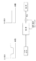
工業的なアニール工程の一例は、図3に示すように、先の溶接形成された筒状部材の溶接シーム304における金属製の筒状部材302のアニールである。溶接シーム(HAZ306)の加熱は、例えば、図3における矢印の方向に筒状部材が前進するに際して、(図で図式的に示される)リニア誘導コイル308に高周波電流を供給することにより達成可能である。
An example of an industrial annealing step is, as shown in FIG. 3, annealing of a metal
上述の誘導溶接工程、抵抗溶接工程、又は誘導アニール工程について、電気負荷は、溶接又は加熱ゾーンにおける負荷回路Q(品質(Quality))因子、インダクタンス、抵抗、及び透磁率に影響する工程変数により生じる溶接又は加熱工程の間で動的に変化する負荷インピーダンスを有する。工程変数が多く、例えば、ワークピースの化学的性質、(ワークピースの筒状部材の周囲長又は厚みといった)ワークピースの寸法、プロセス温度、加工ロールの寸法及び化学的特性、溶接又は加熱電源の出力周波数、製造の溶接又は加熱品のプロセスライン速度又は製造速度、予備の機械装置、誘導コイル又は電気的接点の寸法、物理的構成、組成、及びフェライト素子(例えば、インピーダー)を含み得る。 For the induction welding, resistance welding, or induction annealing steps described above, the electrical load is caused by load circuit Q (Quality) factors in the welding or heating zone, inductance, resistance, and process variables that affect magnetic permeability. It has a load impedance that changes dynamically during the welding or heating process. There are many process variables, such as the chemistry of the workpiece, the dimensions of the workpiece (such as the perimeter or thickness of the tubular member of the workpiece), the process temperature, the dimensions and chemical properties of the machining roll, the welding or heating power source. It may include the output frequency, the process line speed or production rate of the welded or heated product of manufacture, the dimensions of spare machinery, induction coils or electrical contacts, the physical configuration, composition, and ferrite elements (eg, impeders).
溶接又はアニール工程の間の電気負荷回路における動的に変化する負荷特性が原因で、溶接又はアニール電源の出力と電気負荷回路の間には、電源出力から電気負荷回路への最大電力伝送のための動的負荷整合サブシステムが要求される。 Due to the dynamically changing load characteristics in the electrical load circuit during the welding or annealing process, due to the maximum power transmission from the power output to the electrical load circuit between the output of the welding or annealing power supply and the electrical load circuit. Dynamic load matching subsystem is required.
図4は、溶接及びアニール工程のある既知の負荷整合コンセプトを模式的に示し、電源出力インピーダンスと負荷回路インピーダンスの共振により決定されるQ因子がQ曲線上で最大値の時、最大(100パーセント)電力伝送が電源出力周波数fresで生じる。システムが共振外で作動するため、回路のQ因子に基づいて電力伝送が減少する。 FIG. 4 schematically illustrates a known load matching concept with welding and annealing steps, where the Q factor, determined by the resonance of the power output impedance and the load circuit impedance, is maximal (100%) on the Q curve. ) Power transmission occurs at the power output frequency f res . Since the system operates out of resonance, power transfer is reduced based on the Q factor of the circuit.
固有共振回路は、電圧電流比のシフトに帰結し、又は周波数のシフト又は変化に一致する容量とインダクタンスの変化を通じて決定される。図4は、固有共振曲線の模式図である。固有共振は、次式により表され得る。 The intrinsic resonant circuit is determined through a change in capacitance and inductance that results in a shift in voltage-current ratio or is consistent with a shift or change in frequency. FIG. 4 is a schematic diagram of the natural resonance curve. The natural resonance can be expressed by the following equation.

システムに整合装置がないことは、インダクタンスと容量の値が内的に固定されることを意味する。なぜなら、負荷変化が生じ、電力と周波数が、負荷特性により定義されるように様々な電力及び周波数レベルに帰結する定義されたQ曲線の異なる点に自然にシフトするためである。最大の電力出力を達成するためには、所望の調整周波数での電圧電流整合比、負荷Q、及びインダクタンスが、容量とインダクタンスの電源調整又は設定された固定値、選択された共振ピークに整合しなければならない。更には、電圧(電圧供給源)又は電流(電流供給源)を提供するスイッチング回路のタイミングは、最大電力伝送のため、又は共振点に一致するように電圧及び電流を効率的に制御するために設計されるべきである。この最大電力伝送は、周波数のこの1つの共振点でのみ生じる。 The lack of a matching device in the system means that the inductance and capacitance values are internally fixed. This is because load changes occur and the power and frequency naturally shift to different points on the defined Q-curve resulting in different power and frequency levels as defined by the load characteristics. To achieve maximum power output, the voltage-current matching ratio, load Q, and inductance at the desired tuning frequency are matched to the capacitance and inductance power tuning or set fixed values, selected resonant peaks. There must be. Furthermore, the timing of the switching circuit that provides the voltage (voltage source) or current (current source) is for maximum power transmission or to efficiently control the voltage and current to match the resonance point. Should be designed. This maximum power transfer occurs only at this one resonance point of frequency.
ワークピース負荷回路に供給される電力振幅と周波数がワークピース負荷特性とは独立したものである金属溶接及びアニールといった工業用プロセスにおいてワークピースが加熱される、電源ワークピース負荷の一部を形成するワーク誘導コイル又は抵抗接点に電力を供給する微調整されたインバーター出力を有する高周波電源システムの必要性がある。 The power amplitude and frequency supplied to the workpiece load circuit are independent of the workpiece load characteristics. The workpiece is heated in industrial processes such as metal welding and annealing, forming part of the power workpiece load. There is a need for high frequency power supply systems with finely tuned inverter outputs that power work induction coils or resistance contacts.
本発明の一側面は、高周波電源システムであり、溶接又はアニール工程においてワークピース負荷を加熱するための微調整された出力を有する。高周波電源システムは、単相インバーター出力配線と、複数のブリッジスイッチング装置を有するフルブリッジ又はハーフブリッジインバーターを有する。インバーター出力インピーダンス調整及び周波数制御網は、単相インバーター出力配線に接続された制御網入力と制御網出力を有する。システムマイクロプロセッサーコントローラーは、ワークピース負荷のインピーダンスとは独立し得る、フルブリッジ又はハーフブリッジインバーターからワークピース負荷への単相出力の電力伝送と、フルブリッジ又はハーフブリッジインバーターからワークピース負荷への単相出力の可変出力周波数を制御するため、インバーター出力インピーダンス調整及び周波数制御網における複数のブリッジスイッチング装置と1つ又は複数の調整可能なインピーダンス素子に対する制御インターフェースを有する。 One aspect of the present invention is a high frequency power supply system, which has a finely tuned output for heating the workpiece load in a welding or annealing process. The high frequency power supply system has a single phase inverter output wiring and a full bridge or half bridge inverter having a plurality of bridge switching devices. The inverter output impedance adjustment and frequency control network has a control network input and a control network output connected to the single-phase inverter output wiring. The system microprocessor controller can be independent of the impedance of the workpiece load, single-phase output power transfer from the full-bridge or half-bridge inverter to the workpiece load, and single-phase output from the full-bridge or half-bridge inverter to the workpiece load. In order to control the variable output frequency of the phase output, it has an inverter output impedance adjustment and a control interface for a plurality of bridge switching devices in a frequency control network and one or a plurality of adjustable impedance elements.
本発明の上述及び他の側面が本明細書及び添付請求項に明記される。 The above and other aspects of the invention are set forth herein and in the appended claims.
以下の簡潔に要約される添付図面は、本発明に関する理解の例のために提供され、本明細書と添付請求項で更に述べられるように本発明を限定しない。 The following concisely summarized accompanying drawings are provided for an example of understanding of the present invention and are not intended to limit the present invention as further described herein and in the appended claims.
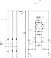
図6は、溶接又はアニール工程においてワークピース負荷30を加熱するための微調整された出力を有する本発明の高周波電源システム10の1つの実施形態を示し、フルブリッジ電流源インバーターが用いられる。図6において、整流器11が、3相交流電流を直流に変換し、また、配線16及び17と固定インダクター18を介してトランジスター12、13、14及び15を備えるインバーター回路に接続される。トランジスターは、金属酸化物半導体電界効果型トランジスター又は他の適切な固体スイッチング装置であり得る。電流センサー19がインバーター、従って、負荷30に供給される電流に比例した出力を提供する。例えば、誘導溶接、又はアニール用途、又は電気抵抗溶接用途において本発明の高周波電源加熱システムが用いられる時、負荷30は、電気配線と誘導コイル、又は、溶接、アニール、さもなければ加熱される電気的接点(接触する部分又は部分(群))を含む。
FIG. 6 shows one embodiment of the high frequency power supply system 10 of the present invention having a finely tuned output for heating the
図7は、本発明の高周波電源システムの別の実施形態20を示し、フルブリッジ電圧源インバーターが用いられる。図7の対応の要素が、図6で用いられた参照番号により指定される。フィルタリングコンデンサ28は、図7の電圧源インバーターでも用いられる。本発明の代替の実施形態では、インバーターがハーフブリッジインバーターである。 FIG. 7 shows another embodiment 20 of the high frequency power supply system of the present invention, in which a full bridge voltage source inverter is used. The corresponding elements of FIG. 7 are designated by the reference numbers used in FIG. The filtering capacitor 28 is also used in the voltage source inverter of FIG. In an alternative embodiment of the invention, the inverter is a half-bridge inverter.
図6又は図7の固体フルブリッジインバーターは、第1単相インバーター出力端子又は配線21と第2単相インバーター出力端子又は配線22を有し、インバーター出力インピーダンス調整及び周波数制御網23におけるインピーダンス素子に給電する。
The solid-state full-bridge inverter of FIG. 6 or 7 has a first single-phase inverter output terminal or
図6及び図7に示した本発明の実施形態においては、インバーター出力インピーダンス調整及び周波数制御網23は、
図にて配置及び相互接続されるように、直列可変リアクトル24及び24’の第1ペアと、直列可変リアクトル24a及び24a’の第2ペアと、直列可変コンデンサ26及び26’の第1ペアと、直列可変コンデンサ26a及び26a’の第2ペアの組み合わせと、
図にて配置及び相互接続されるように、単相インバーター出力配線の間に並列に配置及び接続される並列可変リアクトル25及び25’のペアと、並列可変コンデンサ27a−27a’のペアの組み合わせと、
図に示すように、単相インバーター出力配線の間に並列に配置及び接続される並列可変コンデンサ27を備える。
In the embodiment of the present invention shown in FIGS. 6 and 7, the inverter output impedance adjustment and frequency control network 23 is
The first pair of series
To be placed and interconnected in the figure, 'pairs of parallel variable capacitor 27a-27a' parallel
As shown in the figure, a parallel
図6又は図7に示される本発明の実施形態では、出力インピーダンス調整及び周波数制御網が、L−Cラダー網(LC ladder network)を備え、調整可能な容量性及び誘導性素子が、システムマイクロプロセッサーコントローラー又は溶接又はアニール工程を実施する同等の制御部からの出力により変動可能に制御可能である。 In the embodiment of the invention shown in FIG. 6 or 7, the output impedance adjustment and frequency control network comprises an LC ladder network, and the adjustable capacitive and inductive elements are system micros. It can be variably controlled by the output from a processor controller or an equivalent control unit that performs the welding or annealing process.
本発明の他の例では、多数のL−Cラダー網が、インバーターから負荷への第1及び第2単相出力配線の間に直列又は並列に、さもなければ図6又は図7に示したものとは異なり、特定用途の要求に適するように相互接続される。本発明の他の実施形態においては、制御網23における幾つかの誘導性及び容量性素子が、調整可能な誘導性及び容量性素子と組み合わされて固定値のものである。 In another example of the invention, a number of LC ladder networks are shown in series or in parallel between the first and second single-phase output wires from the inverter to the load, or else shown in FIG. 6 or 7. Unlike the ones, they are interconnected to suit the requirements of a particular application. In another embodiment of the invention, some inductive and capacitive elements in the control network 23 are of fixed value in combination with adjustable inductive and capacitive elements.
本発明の幾つかの例においては、負荷特性独立オペレーションの代替として、図6又は図7において負荷インピーダンスが変化し、反射のリアクタンスと抵抗の変化に帰結し、インバーター出力インピーダンス調整及び周波数制御網23は、負荷インピーダンスの変化を補償して所望の共振点を維持する。 In some examples of the present invention, as an alternative to the load characteristic independent operation, the load impedance changes in FIG. 6 or 7, resulting in changes in the reactance and resistance of the reflection, and the inverter output impedance adjustment and frequency control network 2 3 compensates for the change in load impedance and maintains a desired resonance point.
本発明の幾つかの実施形態では、調整可能な容量性素子は、システムマイクロプロセッサーコントローラーからの出力により可変に制御され、共振電力振幅、電圧電流比又は周波数といった負荷特性とは独立して、高周波電源システムから負荷への出力電力振幅;電源システムから負荷への出力電圧と出力電流の比;又は電源システムから負荷への電圧と電流の出力周波数を制御する。 In some embodiments of the invention, the adjustable capacitive element is variably controlled by the output from the system microprocessor controller and has a high frequency independent of load characteristics such as resonant power amplitude, voltage-current ratio or frequency. Controls the output power amplitude from the power supply system to the load; the ratio of the output voltage to the output current from the power supply system to the load; or the output frequency of the voltage and current from the power supply system to the load.
本発明の幾つかの実施形態では、インバーター出力インピーダンス調整及び周波数制御網23における調整可能なリアクトル及び/又はコンデンサに対するシステムマイクロプロセッサー制御が、負荷30の特性の変化を補償するために用いられ、負荷特性の変化にもかかわらず共振点が維持可能である。例えば、負荷のインダクタンスが増加するならば、インバーター出力インピーダンス調整及び周波数制御網のインダクタンスが減じられ、全体として同等のシステムインダクタンスが維持され、負荷特性の変化にもかかわらず共振点が同一であることに帰結する。更には、負荷のQ因子が減じられるならば、可変容量及びインダクタンスに関するシステムマイクロプロセッサーコントローラーを通じてインバーター出力インピーダンス調整及び周波数制御網のQ因子も減じられ、電力伝送の共振点が同等であることに帰結し、高周波電源システムの特性が負荷特性に整合する。
In some embodiments of the invention, inverter output impedance adjustment and system microprocessor control over adjustable reactors and / or capacitors in the frequency control network 23 are used to compensate for changes in the characteristics of the
本発明の幾つかの実施形態では、インバーター出力インピーダンス調整及び周波数制御網23における調整可能なリアクトル及び/又はコンデンサに対するシステムマイクロプロセッサー制御は、高周波電源システムと負荷回路の組み合わせの固有共振点を固有共振のユーザー選択点に変化するために用いられる。例えば、負荷特性が変化しないままならば、典型的には安定した溶接と加熱工程状態の下、調整可能なインダクタンス及び/又は容量の固有共振のユーザー選択点への変動を通じて共振周波数の異なる値が選択可能である。 In some embodiments of the invention, the inverter output impedance adjustment and the system microprocessor control over the adjustable reactor and / or capacitor in the frequency control network 23 inherently resonate the intrinsic resonance point of the combination of the high frequency power supply system and the load circuit. It is used to change to the user selection point of. For example, if the load characteristics remain unchanged, then under stable welding and heating process conditions, different values of resonance frequency will typically occur through variations of the adjustable inductance and / or capacitance to the user-selected point. It is selectable.
共振周波数での最大電力伝送を得るため、電源スイッチングを制御するスイッチング回路のタイミングが、パルス幅変調(PWM)により調整可能であり、変化する出力共振点を介して最大電力が負荷30に伝送可能である。PWM技術は、また、図6又は図7におけるトランジスタスイッチング装置12、13、14、及び15の効率を維持するためにも使用可能である。
In order to obtain the maximum power transmission at the resonance frequency, the timing of the switching circuit that controls the power supply switching can be adjusted by pulse width modulation (PWM), and the maximum power can be transmitted to the
図8(a)乃至図8(c)に示したシステム制御要素は、システムマイクロプロセッサーコントローラー又は同等の1つ又は複数の制御部に設けることができる。システム制御要素は、図8(a)における高周波コントローラー、電圧、電流及び周波数比較器及び電流比較器、図8(b)における整合制御回路、及び図8(c)における電圧/電流フィードバック回路を含むことができる。 The system control elements shown in FIGS. 8 (a) to 8 (c) can be provided in the system microprocessor controller or one or more equivalent control units. System control elements include a high frequency controller, voltage, current and frequency comparator and current comparator in FIG. 8 (a), a matching control circuit in FIG. 8 (b), and a voltage / current feedback circuit in FIG. 8 (c). be able to.
システムマイクロプロセッサーコントローラーへのセンサーフィードバックが、任意の調整可能なリアクトルのために提供され、(可変インダクタンス値の関数として)リアクトル可動部の位置;図8(a)及び図8(b)に示すようなリアクトルに亘る電圧とリアクトルに流れる電流を検出する。同様、システムマイクロプロセッサーコントローラーへのセンサーフィードバックが、また、任意の調整可能なコンデンサに追加され、(可変容量値の関数として)コンデンサ可動部の位置、コンデンサに亘る電圧やコンデンサに流れる電流を検出する。これらの調整可能なリアクトル及びコンデンサの測定値が、設定出力を維持及び調整するための閉ループ制御のために用いられる。インバーター出力インピーダンス調整及び周波数制御網から負荷への出力電力、制御網から負荷への出力電流、及び制御網からの出力周波数が、本発明の幾つかの実施形態において測定され、正確な共振点、負荷への電力、負荷でのインピーダンス変化を検出する。 Sensor feedback to the system microprocessor controller is provided for any adjustable reactor and the location of the reactor moving parts (as a function of the variable inductance value); as shown in FIGS. 8 (a) and 8 (b). Detects the voltage across the Reactor and the current flowing through the Reactor. Similarly, sensor feedback to the system microprocessor controller is also added to any adjustable capacitor to detect the position of the capacitor moving part (as a function of variable capacitance value), the voltage across the capacitor and the current flowing through the capacitor. .. These adjustable reactor and capacitor measurements are used for closed-loop control to maintain and adjust the set output. Inverter output impedance adjustment and frequency The output power from the control network to the load, the output current from the control network to the load, and the output frequency from the control network are measured in some embodiments of the present invention and are accurate resonance points. Detects power to load and impedance change with load.
本発明の幾つかの実施形態では、測定された電圧、電流、及び周波数のセンサーフィードバックから、測定信号が、次に、図8(a)に示す測定比較器に提供され、各リアクトル又はコンデンサに関する個別のアクチュエーター(M)に出力調整制御信号を生成する。これらの出力調整制御信号は、各可変リアクトル及び/又はコンデンサに関連の可動部の動きを正確に制御するために用いられ、システムマイクロプロセッサーコントローラーにより決定される共振点又は共振点外のいずれかを維持する。 In some embodiments of the invention, from the measured voltage, current, and frequency sensor feedback, a measurement signal is then provided to the measurement comparator shown in FIG. 8 (a) for each actuator or capacitor. An output adjustment control signal is generated in the individual actuator (M). These output adjustment control signals are used to accurately control the movement of moving parts associated with each variable reactor and / or capacitor, either at or outside the resonance point determined by the system microprocessor controller. maintain.
本発明の幾つかの実施形態では、システムマイクロプロセッサーコントローラーは、開ループシステムコントローラーとして動作し、高周波電源システムの共振点が負荷インピーダンスと変化することを許容し、インバーターのスイッチング装置に対する既存のマイクロプロセッサー出力制御を調整して電力伝送の最大出力を維持し、又は、共振外にシステムが移動するため、インバーターのスイッチング装置に対する既存のマイクロプロセッサー出力制御を電力伝送の最大出力未満に維持する。 In some embodiments of the invention, the system microprocessor controller acts as an open-loop system controller, allowing the resonance point of the high frequency power supply system to change with the load impedance, and the existing microprocessor for the inverter switching device. Adjust the output control to maintain the maximum output of the power transmission, or keep the existing microprocessor output control for the inverter switching device below the maximum output of the power transmission as the system moves out of resonance.
代替として、本発明の他の実施形態においては、システムマイクロプロセッサーコントローラーが、閉ループ制御コントローラーとして動作し、マイクロプロセッサーコントローラーに入力されるユーザー選択出力周波数にシステム共振点を動かし、インバーターのスイッチング装置に対する既存のマイクロプロセッサー出力制御を調整して電力伝送の最大出力を維持し、又は、共振外にシステムが移動するため、インバーターのスイッチング装置に対する既存のマイクロプロセッサー出力制御を電力伝送の最大出力未満に維持する。 Alternatively, in another embodiment of the invention, the system microprocessor controller acts as a closed-loop control controller, moving the system resonance point to a user-selected output frequency input to the microprocessor controller, and existing for the inverter switching device. Adjust the microprocessor output control of to maintain the maximum output of the power transmission, or keep the existing microprocessor output control for the inverter switching device below the maximum output of the power transmission because the system moves out of resonance. ..
図8(b)は、高周波コントローラー38及び電圧、電流、周波数比較器35として図8(a)に示した高周波加熱電源制御システムと利用可能である高周波電源システムの幾つかの実施形態のための制御ブロック図の一例である。
FIG. 8 (b) is for some embodiments of the high frequency heating power control system shown in FIG. 8 (a) and the available high frequency power supply systems as the
図8(c)は、図8(a)に示した高周波加熱電源制御システムと利用可能である電力振幅制御ブロック図の一例であり、制御システムが、出力電力の調整を維持して入力電力変動及び変化を補償する能力を有する。 FIG. 8 (c) is an example of a power amplitude control block diagram that can be used with the high frequency heating power supply control system shown in FIG. 8 (a), in which the control system maintains the adjustment of the output power and the input power fluctuates. And has the ability to compensate for changes.
図9は、本発明の高周波加熱電源システムの動作を図式的に示す。図9に図式で示される電子負荷整合プロセスは、本発明の調整可能なリアクトル及び/又はコンデンサ部と組み合わせてハードスイッチング工程を用いる。本発明のハードスイッチング工程では、ハード・ターン・オンは、ある電流転流時間(current commutation time)で通電スイッチング装置上の全転流電圧降下(total commutation voltage drop)により特徴付けられ、ハード・ターン・オフは、その低下前、電流が流れ続ける間、転流電圧値まで上昇した電圧により特徴付けられる。ハード・ターン・オン又はハード・ターン・オフは、インバーターのスイッチング装置における高電力損失ピークを生じさせる。代替の動作モードにおいては、図5の曲線が、規定の最大出力電力を得る方法を表す。この方法は、共振点外の時に最大電力を達成するために入力に加えられたKVAを要求する。反対に、図9の曲線は、ハードスイッチングと、負荷インピーダンスが変化するために共振点をシフトさせる網23の可変誘導性及び容量性リアクタンス制御により最大出力電力を得るための本発明の1つの方法を表す。 FIG. 9 schematically shows the operation of the high frequency heating power supply system of the present invention. The electronic load matching process graphically shown in FIG. 9 uses a hard switching process in combination with the adjustable reactor and / or capacitor section of the present invention. In the hard switching process of the present invention, the hard turn-on is characterized by a total commutation voltage drop on the energized switching device at a current commutation time and is a hard turn. Off is characterized by a voltage that rises to the commutation voltage value before it drops, while the current continues to flow. Hard turn-on or hard turn-off results in high power loss peaks in inverter switching equipment. In the alternative mode of operation, the curve in FIG. 5 represents how to obtain the specified maximum output power. This method requires KVA applied to the input to achieve maximum power when outside the resonant point. On the contrary, the curve of FIG. 9 is one method of the present invention for obtaining maximum output power by hard switching and variable inductive and capacitive reactance control of the network 23 which shifts the resonance point due to the change of load impedance. Represents.
図10は、本発明の出力インピーダンス調整及び周波数制御網又はインダクターとコンデンサの固定配列と使用可能である代替のPWM変調可変スイッチング周波数電源を図式的に示す。電界効果型トランジスターがインバーターで用いられるならば、インバーターの電界効果型トランジスタのスイッチングの最大効率及び電力伝送のため、トランジスタスイッチングのタイミングを制御するためにPWM技術が使用可能である。 FIG. 10 schematically shows an output impedance adjustment and frequency control network of the present invention or a fixed array of inductors and capacitors and an alternative PWM modulation variable switching frequency power supply that can be used. If field-effect transistors are used in an inverter, PWM technology can be used to control the timing of transistor switching for maximum efficiency and power transmission of the inverter's field-effect transistors.
本発明の幾つかの実施形態では、1つ又は複数の調整可能なリアクトルペアが、2つの通電バスの間の空いた容積空間と、その空いた容積挿入空間内に可変位置で挿入される1つのコアから形成可能であり、容積と面積の減少で低インダクタンスになる。空いた容積空間の構成は、例えば、リアクトルコアが挿入可能である、箱、台形、三角形、円錐形、楕円形、卵形、又は任意の他の空いた容積幾何形状といった幾何形状の形態であり得る。空いた容積空間は、リアクトルのペアのそれぞれのために要求される最大インダクタンスに基づいて選択される。コアは、それが挿入される空いた容積形状の反対形状を備え、誘導性面積の全境界の周囲にコアと配線の間の正確な同等の隙間を形成し、コアが空いた容積空間に完全に挿入される時、可変リアクトルのペアそれぞれについてインダクタンスの最小値が維持される。コアは、手動で、又は、モーター又は他のアクチュエーターの使用を介して自動的に可動であり、コアが空いた容積空間内から引き出されるに応じてインダクタンスが最小から最大へアナログ変化する。空いた容積空間とコアの幾何形状のテーパーは、特定の用途のために構成され、例えば、インダクタンスのリニア変化、インダクタンスの対数変化、又は特定の用途のためのインピーダンス負荷整合条件に依存した他の曲線形状に帰結する。モーター又は他のアクチュエーターのいずれかが、図8(b)に示すエンコーダーEといった位置検出手段を介して、システムマイクロプロセッサーコントローラーにおける整合制御回路に正確なフィードバックを提供し、又は、代替的に、空いた容積空間内外へのコアの作動又は動きが、インダクタンスの変化に相関する距離の正確な測定値を提供するように適合される。代替として、次の方程式により電流のある変化率について生成された電圧量からシステムマイクロプロセッサーコントローラーによりインダクタンスの変化が導出されることもできる。
![]()
![]()
本発明では、図6又は図7のインピーダンス調整及び周波数制御網23における可変リアクトルペア24−24’、24a−24a’及び25−25’のいずれかが、本発明の一実施形態において、例えば、図11(a)及び図11(b)、図13又は図14に個々に表されるように、相補的な円錐部分、くさび形(2つの三角形と3つの台形面から規定される多面体)部分又は放物線円錐部分として、図示のように、銅といった導電性シート材料から構成される単一の可動な幾何学的な形状のインサートコアと、定置の分割バスを有するリアクトルの幾何学的な形状のペアから形成可能である。短絡されたインサートコア部が相補的なバス部との関係において内側又は外側に動かされ、短絡インサートコア部の誘導電流の振幅が、相補的なバス部に流れる電流により生じる磁束場に結合する可変磁束場を確立し、幾何インサートコア部が相補的な幾何バス部に完全に挿入される時の最小値から幾何インサートコア部が短絡インサートコア部と幾何バス部の間に結合した磁界が最も広くなる位置に引き出された時の最大値までの可変インダクタンス範囲を有し得るインダクターのペアのそれぞれについて交流電流(AC)バスの端子で可変インダクタンスを確立する。第1に、特定用途のために選択されたインサートコア部とバス素子の磁気的相互作用の幾何学形態は、この幾何学的な形状のインダクターで達成可能であるインダクタンスの変化の精度の程度を決定し、この精度の程度は、電源制御システムが加熱工程を実行している時、電源の出力周波数の調整精度の程度に関する。 In the present invention, any of the variable reactor pairs 24-24', 24a-24a' and 25-25' in the impedance adjustment and frequency control network 23 of FIG. 6 or 7 is, for example, in one embodiment of the present invention. Complementary conical, wedge-shaped (polyhedron defined by two triangles and three trapezoidal surfaces) portions, as individually represented in FIGS. 11 (a) and 11 (b), 13 or 14. Or as a parabolic conical portion, as shown, in the geometric shape of a reactor with a single movable geometrically shaped insert core composed of a conductive sheet material such as copper and a stationary split bath. It can be formed from pairs. The short-circuited insert core is moved inward or outward in relation to the complementary bus, and the amplitude of the induced current in the short-circuit insert core is variable to be coupled to the magnetic flux field generated by the current flowing in the complementary bus. The magnetic flux field is established and the geometric insert core is short-circuited from the minimum value when the geometric insert core is completely inserted into the complementary geometric bus. The magnetic field coupled between the insert core and the geometric bus is the widest. A variable inductance is established at the terminals of the alternating current (AC) bus for each pair of inductors that may have a variable inductance range up to the maximum value when pulled out to the desired position. First, the geometric form of the magnetic interaction between the insert core and the bus element selected for a particular application determines the degree of accuracy of the change in inductance that can be achieved with an inductor of this geometry. Determined, the degree of this accuracy relates to the degree of adjustment accuracy of the output frequency of the power supply when the power supply control system is performing the heating process.
例えば、本発明の1つの実施形態では、図11(a)と図11(b)に可変リアクトルペア60が示され、図11(a)と図11(b)の両側矢印に示されるように、単一の短絡幾何学的な形状インサートコア部62が、定置の分割バス部64の相補的な幾何学的な形状の分割バス円錐部64a及び64bの内外に動かされる。インサートコア部62の誘導電流の振幅が、定置の分割バス部64の相補的な幾何学的な形状の分割バス円錐部64a及び64bに流れる交流電流から可変磁束場(可変エネルギー場とも呼ばれる)を確立し、幾何学的な形状のインサートコア部62が相補的な幾何学的な形状の分割円錐バス部64a及び64bに完全に挿入された時の最小インダクタンス値から、インサートコア部62と定置の分割バス部64の間で形状付けられた挿入空間における可変エネルギー場が最大値である、例えば、図11(a)に示す位置に幾何学的な形状のインサートコア部62が引き出される時の最大インダクタンス値までの可変インダクタンス範囲を有し得るリアクトルのペアそれぞれについて交流電流バスの分割電気バス端子部A1−B1及びA2−B2で可変インダクタンスを確立する。図11(c)は、可変リアクトルペア24a−24a’として、図6又は図7の高周波電源システムで接続された可変リアクトルペア60を示す。定置の分割バス部64は、電気的に絶縁された分割円錐バス部64a及び64bと、(円錐バス部64aに関連の)分割電気バス端子部A2及びB2と、(円錐バス部64bに関連の)分割電気バス端子部A1及びB1を備える。つまり、電気的に相互接続された円錐バス部64aと分割電気バス端子部A2及びB2が、電気的に相互接続されたバス部64bと端子部A1及びB1から空間的に分離される。
For example, in one embodiment of the invention, the
磁気的に相互作用する可動なインサートコア部と定置のバス素子の幾何学的な形状が、幾何学的な形状のリアクトルペアで達成可能であるインダクタンスの変化の精度の程度に基づいて、特定用途のために選択され、この精度の程度は、本発明の高周波電源の出力周波数の調整精度の程度に関する。 Specific applications based on the degree of accuracy of the change in inductance that the geometric shape of the magnetically interacting movable insert core and the stationary bus element can be achieved with a geometrically shaped reactor pair. This degree of accuracy relates to the degree of adjustment accuracy of the output frequency of the high frequency power supply of the present invention.
各幾何学的な形状のリアクトルペアが、リアクトルのペア、例えば、図6又は図7のリアクトルペア24−24’、24a−24a’及び25−25’を備え、例えば、図6又は図7の相互接続鎖線Xにより示されるようにペアで調整可能であり、例えば、リアクトルペア24a及び24a’について、図11(a)及び図11(b)に示すように、図11(a)及び図11(b)のアクチュエーターM’が図8(a)に示すように可動なインサートコア又はモーターM3に取り付けられた状態で定置の分割バス部64の幾何学的な形状の分割バス部の内外にインサートコア部62を動かすことにより調整可能である。
Each geometrically shaped actuator pair comprises a pair of actuators such as the reactor pairs 24-24', 24a-24a'and 25-25' of FIG. 6 or FIG. 7, for example of FIG. 6 or FIG. It is adjustable in pairs as indicated by the interconnected chain line X, for example, for
図12(a)及び図12(b)は、図11(a)及び図11(b)の円錐形状リアクトルペア60を有する円錐形インサートコア部62のための磁性材料(例えば、フェライト62a)の使用を示す。図12(a)では、円錐型のインサートコア部62aは、中実又は中空磁性材料インサートコア部を備える。図12(b)では、円錐型のインサートコア部62bは、インサートコア部の外周部を形成するフェライトロッドのアレイを備える。
12 (a) and 12 (b) show the magnetic material (eg, ferrite 62a) for the conical
図13は、本発明の高周波電源システムで用いられることができる本発明の高周波可変リアクトル90の別例を示す。高周波可変リアクトル90は、2つの三角形と3つの台形面から規定される多面体の幾何形状の単一の短絡インサートコア部92を備え、本明細書ではくさび形部の一般名により特定され、図13の両側矢印により示されるように、定置の分割バス部94の定置の相補的な幾何学的な形状の分割くさび形バス部94a及び94bの内外に動かされる。インサートコア部92における誘導電流の振幅は、定置の分割バス部94の相補的な幾何学的な形状の分割くさび形バス部94a及び94bに流れる交流電流から可変磁束場(可変エネルギー場とも呼ばれる)を確立し、幾何学的な形状のインサートコア部92が相補的な幾何学的な形状の分割円錐バス部94a及び94bに完全に挿入された時の最小インダクタンス値から、インサートコア部92と定置の分割バス部94の間で形状付けられた挿入空間における可変エネルギー場が最大値である位置に幾何学的な形状のインサートコア部92が引き出される時の最大インダクタンス値までの可変インダクタンス範囲を有し得るリアクトルのペアそれぞれについて交流電流バスの分割電気バス端子部A1−B1及びA2−B2で可変インダクタンスを確立する。可変リアクトルペア90は、可変リアクトルペア24−24’、24a−24a’及び/又は25−25’として、図6又は図7の高周波電源システムにおいて接続される。定置の分割バス部94は、電気的に絶縁された分割くさび形バス部94a及び94bと、(くさび形バス部94aに関連の)分割電気バス端子部A2及びB2と、(くさび形バス部94bに関連の)分割電気端子部A1及びB1を備える。つまり、電気的に接続されたバス部94aと端子部A2及びB2は、電気的に接続されたバス部94bと端子部A1及びB1から空間的に分離される。
FIG. 13 shows another example of the high frequency
図14は、本発明の高周波電源システムで用いられることができる高周波可変リアクトル110の別例を示す。高周波可変リアクトル110は、図14の両側矢印により示されるように定置の分割バス部114の定置の相補的な幾何学的な形状の分割楕円放物面バス部114a及び114bの内外に可動である楕円放物面の幾何形状の単一の短絡インサートコア部112を備え、インサートコア部112における誘導電流の振幅は、定置の分割バス部114の相補的な幾何学的な形状の分割円錐型バス部114a及び114bに流れる交流電流から可変磁束場(可変エネルギー場とも呼ばれる)を確立し、幾何学的な形状のインサートコア部112が相補的な幾何学的な形状の分割円錐型バス部114a及び114bに完全に挿入された時の最小インダクタンス値から、インサートコア部112と定置の分割バス部114の間で形状付けられた挿入空間における可変エネルギー場が最大値である位置に幾何学的な形状のインサートコア部112が引き出される時の最大インダクタンス値までの可変インダクタンス範囲を有し得るリアクトルのペアそれぞれについて交流電流バスの分割電気バス部端子部A1−B1及びA2−B2で可変インダクタンスを確立する。可変リアクトルペア110は、可変リアクトルペア24−24’、24a−24a’及び/又は25−25’として、図6又は図7の高周波電源システムにおいて接続される。定置の分割バス部114は、電気的に絶縁された分割円錐型バス部114a及び114bと、(楕円放物面バス部114aに関連の)分割電気バス端子部A2及びB2と、(楕円放物面バス部114bに関連の)分割電気バス端子部A1及びB1を備える。つまり、電気的に接続されたバス部114aと端子部A2及びB2は、電気的に接続されたバス部114bと端子部A1及びB1から空間的に分離される。
FIG. 14 shows another example of a high frequency
本発明の別例では、本発明の幾何学的な形状の高周波リアクトルは、幾何形状のインサートコア部と定置の分割バス部の間で形状づけられた挿入空間に応じた特定用途で要求される可変インダクタンス・プロファイルに依存して、他の幾何形体であり得、例えば、ピラミッド形である。例えば、本発明の高周波電気加熱システムでの加熱を達成するためにインダクタンスのリニア又は対数変化が特定の高周波可変リアクトルにより要求される用途では、特定の幾何形状が、別の幾何形状よりも微調整されたインダクタンス・プロファイルを提供し得る。 In another example of the present invention, the geometrically shaped high frequency inductance of the present invention is required for a specific application depending on the insertion space shaped between the geometrically shaped insert core portion and the stationary split bus portion. Depending on the variable inductance profile, it can be another geometry, for example a pyramid. For example, in applications where linear or logarithmic changes in inductance are required by a particular high frequency variable reactor to achieve heating in the high frequency electric heating system of the present invention, one geometry may be fine-tuned over another geometry. Can provide a defined inductance profile.
図15(a)乃至図15(d)は、本発明の高周波電源システムと使用可能である本発明の高周波可変リアクトル70の一実施形態を示す。高周波可変リアクトル70は、2巻き可変インダクターペア70を備え、幾何形状が、円錐部であり、ペアの各可変リアクトル、例えば、図6又は図7におけるリアクトル24a及び24a’が、それぞれ、その独自の円錐形状のインサートコア部72a及び72bと、その独自の円錐形状の2巻き分割バス部74a及び74bを有する。第1の定置の分割バス部は、電気的に絶縁された2巻き分割バス部74aと(2巻き分割バス部74aに接続された)分割電気端子部A1及びB1を備え、第2の定置の分割バス部は、電気的に絶縁された2巻き分割バス部74bと(2巻き分割バス部74bに接続された)分割電気バス端子部A2及びB2を備える。つまり、電気的に接続された2巻きバス部74aと端子部A1及びB1は、電気的に接続された2巻きバス部74bと端子部A2及びB2から空間的に分離される。
15 (a) to 15 (d) show an embodiment of the high frequency
図16(a)及び図16(b)は、本発明の高周波電源システムと使用可能である本発明の高周波可変リアクトル120の別例を示す。分割電気バス端子部A1及びA2が一緒に電気的にバス端子A1’に接続され、B1及びB2がバス端子B1’に一緒に電気的に接続され、可変リアクトルのペアが単一のリアクトル120を形成することを除いて、図12(a)及び図12(b)に示された実施形態は、図11(a)及び図11(b)に示されたものと同様である。この実施形態では、インダクターペアは、図16(c)に示されるように、バス端子A1’及びB1’の間の単一のインダクター120として構成され、これは、本発明の幾つかの実施形態では、可変直列リアクトルペア24a及び24a’を単一の可変リアクトル120で置換する。同様、図16(a)及び図16(b)に示されたようにリアクトルペアを修正することにより、図6又は図7における他のリアクトルペアが、単一のリアクトルで置換され得る。
16 (a) and 16 (b) show another example of the high frequency
本発明の高周波電源システムの幾つかの例では、インダクタンスの固定値を有するインダクターが、本発明のリアクトルペアの任意の1つ又は複数の可変リアクトルに直列に接続され得る。 In some examples of high frequency power supply systems of the invention, inductors with fixed inductance values may be connected in series to any one or more variable reactors of the reactor pair of the invention.
本発明の高周波可変リアクトルの幾何学的な形状のペアそれぞれについて可動インサートコア部は、適切なアクチュエーター、例えば、リアクトルペア24a−24a’及び25−25’について個別に図8(a)に示されたモーターM2及びM3で定置の幾何学的な形状の分割バス部の内外に移動可能であり、モーターは、例えば、図において可動なインサートコア部とアクチュエーターM’を接続する、例えば、図11(a)及び図11(b)に図示の鎖線で模式的に示されるように、インサートコア部へのリニア、反転可能な出力接続を有する。 For each geometrically shaped pair of high frequency variable reactors of the invention, the movable insert core section is shown separately in FIG. 8 (a) for suitable actuators, such as reactor pairs 24a-24a'and 25-25'. The motors M2 and M3 can be moved in and out of the stationary geometrically shaped split bus section, and the motor connects, for example, the movable insert core section and the actuator M'in the figure, eg, FIG. 11 ( As schematically shown by the chain line shown in a) and FIG. 11 (b), it has a linear, inverting output connection to the insert core portion.
本発明の高周波可変リアクトルの幾何形状のペアの加熱は、定置の分割バス部及び/又は可動インサートコア部に熱的に接触した、例えば、冷却管における冷却媒体の循環により消散可能である。 The heating of the geometric pair of high frequency variable reactors of the present invention can be dissipated by thermal contact with the stationary split bath and / or movable insert core, eg, by circulation of the cooling medium in the cooling tube.
本発明の他の例においては、幾何学的な形状のリアクトルペアは、特定用途に要求される可変インダクタンス・プロファイルに依存して、他の幾何形体であり得、例えば、ピラミッド形である。例えば、特定のリアクトルが、本発明の高周波電源システムでの加熱を達成するためにインダクタンスのリニア又は対数変化を要求する用途では、特定の幾何形状は、別の幾何形状よりも微調整されたインダクタンス・プロファイルを提供し得る。 In another example of the invention, the geometrically shaped reactor pair can be another geometry, eg, a pyramid, depending on the variable inductance profile required for a particular application. For example, in applications where a particular reactor requires a linear or logarithmic change in inductance to achieve heating in the high frequency power supply system of the present invention, a particular geometry has a finer tuned inductance than another geometry. -Can provide a profile.
特定用途における最小インダクタンスを達成するための可動なインサートコアの完全な挿入は、インサートコアが、幾何学的な形状の分割バス部内の場所に位置付けられる時にインダクタンスを測定し、次に、インサートコアの最大インダクタンス位置を設定するために、用途における最大要求インダクタンスが達成される位置にインサートコアを引き出すことにより決定可能である。 Full insertion of the movable insert core to achieve the minimum inductance in a particular application measures the inductance when the insert core is positioned within the geometrically shaped split bus section, and then of the insert core. To set the maximum inductance position, it can be determined by pulling the insert core to a position where the maximum required inductance in the application is achieved.
本発明の幾つかの実施形態では、図6又は図7におけるインピーダンス調整及び周波数制御網23の1つ又は両方の可変コンデンサペア27a−27a’及び26a−26a’は、図17(a)及び図17(b)に示すように形成可能であり、図6又は図7における可変コンデンサペア26−26’は、図6又は図7のインピーダンス調整及び周波数制御網から、図17(c)に詳細に示されるように、挿入され、また空間的に離間した、導電性プレート26及び26’に個別に接続された可動バス部A1,A2,D1,及びD2から形成される。
In some embodiments of the present invention, one or both variable capacitor pairs 27a-27a'and 26a-26a' of the impedance adjustment and frequency control network 23 in FIG. 6 or 7 are shown in FIGS. 17 (a) and 7 (a). It can be formed as shown in 17 (b), and the variable capacitor pair 26-26'in FIG. 6 or 7 is detailed in FIG. 17 (c) from the impedance adjustment and frequency control network of FIG. 6 or 7. As shown, it is formed from movable bus portions A1, A2, D1, and D2 that are inserted and spatially separated and individually connected to the
本発明の幾つかの実施形態では、1つ又は複数の調整可能な幾何学的な形状のリアクトルペアとコンデンサペアの組み合わせが、本発明の出力インピーダンス調整及び周波数制御網において用いられる。 In some embodiments of the present invention, a combination of one or more adjustable geometrically shaped reactor pairs and capacitor pairs is used in the output impedance adjustment and frequency control networks of the present invention.
図18(a)は、負荷への電力振幅と周波数を制御しているインバーター出力インピーダンス調整及び周波数制御網23における負荷特性と容量とインダクタンス設定で与えられる実際の稼働点を示す手段として、ターゲットのユーザー視覚化を許容するグラフィック・ユーザーインターフェースの一例を示す。溶接又は加熱処理工程の間の任意の時間に負荷インピーダンスとは独立してシステム動作周波数とQ基準を正確に設定するための発明の高周波電源システムのユーザーへの表示として座標系の中心が用いられることができる。 FIG. 18A shows the target as a means of showing the actual operating points given by the load characteristics, capacitance and inductance setting in the inverter output impedance adjustment and frequency control network 23 that control the power amplitude and frequency to the load. An example of a graphic user interface that allows user visualization is shown. The center of the coordinate system is used as a user display of the high frequency power supply system of the invention to accurately set the system operating frequency and Q reference independently of the load impedance at any time during the welding or heat treatment process. be able to.
図18(b)は、本発明の高周波電源システムが使用可能である鍛接又は加熱装置の溶接周波数と溶接電力を個別に制御するための図示されたグラフィック・ユーザーインターフェース上のビジュアル制御バー42及び44を表示するシステムマイクロコントローラーの一例を示す。装置のユーザーが、装置の溶接周波数又は溶接電力が変更されるように制御バー42(HAZ幅)又は44(電力)のいずれかの位置を変更する時、マイクロコントローラーは、現に又は実質的にリアルタイムで、HAZ幅の予測値に関連した量(quantity)を表示する。本発明の幾つかの実施形態では、マイクロコントローラーは、また、グラフィック・ユーザーインターフェース上に最適な溶接周波数も表示し、また、図18(b)に示されるような2次元グラフ46上の予測されたHAZ幅と最適なHAZ幅の間の差のパーセントも示す。図18(b)のディスプレイが、図18(a)のグラフィック・ユーザーインターフェースを組み込み、溶接又は加熱処理工程の任意の時間で、負荷インピーダンスとは独立してシステム動作周波数及びQ因子基準を正確に設定するため、溶接又は加熱工程の追加の制御を鍛接又は加熱装置のユーザーに与える。
FIG. 18B shows visual control bars 42 and 44 on the illustrated graphic user interface for individually controlling the welding frequency and welding power of a forge welding or heating device in which the high frequency power supply system of the present invention can be used. An example of a system microcontroller that displays is shown. When the user of the device changes the position of either the control bar 42 (HAZ width) or 44 (power) so that the welding frequency or welding power of the device is changed, the microcontroller actually or substantially in real time. Displays the quantity associated with the predicted value of the HAZ width. In some embodiments of the invention, the microcontroller also displays the optimum welding frequency on the graphic user interface and is predicted on the
代替として、本発明の幾つかの実施形態では、ヒト・機械・インターフェース制御パネルは、単一の相乗的なノブといった一体化された単一のユーザー入力制御装置を有し、電力及び周波数ディスプレイと熱影響ゾーンサイズの組み合わせで高周波電源システムからの電力振幅出力及び周波数出力を制御する。 Alternatively, in some embodiments of the invention, the human-machine-interface control panel has a single integrated user input control device, such as a single synergistic knob, with a power and frequency display. The power amplitude output and frequency output from the high frequency power supply system are controlled by the combination of thermal influence zone sizes.
上述の記述では、説明の目的のため、例や実施形態の完全な理解を提供するため、多数の特定の要求や幾つかの特定の詳細を提示した。しかしながら、これらの幾つかの特定の詳細抜きで1つ又は複数の他の例や実施形態が実施され得ることは、当業者には明らかである。記述した特定の実施形態は、本発明を限定するのではなくそれを説明するために提供される。 In the above description, for purposes of illustration, a number of specific requirements and some specific details have been presented to provide a complete understanding of the examples and embodiments. However, it will be apparent to those skilled in the art that one or more other examples or embodiments may be practiced without some of these specific details. The particular embodiments described are provided to illustrate, but not limit, the invention.
本明細書に亘る「一例又は実施形態」、「例又は実施形態」「1つ又は複数の例又は実施形態」又は「異なる例又は実施形態」への参照は、例えば、特定の特徴が、本発明の実施に含まれ得ることを意味する。明細書において、開示の円滑化や様々な発明の側面の理解を助ける目的で、幾つかの時、様々な特徴が、単一の例、実施形態、図、又は、その記述において一緒にグループ化される。 References to "one example or embodiment", "example or embodiment", "one or more examples or embodiments" or "different examples or embodiments" throughout the specification are, for example, specific features of the present invention. It means that it can be included in the practice of the invention. In the specification, various features are sometimes grouped together in a single example, embodiment, figure, or description thereof for the purpose of facilitating disclosure and helping to understand aspects of various inventions. Will be done.
好適な例及び実施形態に関して本発明を記述した。明確に述べてきたものとは別に、均等、代替及び変更が可能であり、本発明の範囲内にある。本明細書の教示の利益を有する当業者は、本発明の範囲から逸脱することなくそこに変更を為し得る。 The present invention has been described with respect to suitable examples and embodiments. Apart from what has been explicitly stated, equality, substitution and modification are possible and are within the scope of the present invention. Those skilled in the art who have the benefit of the teachings herein may make changes herein without departing from the scope of the invention.
Claims (19)
複数のブリッジスイッチング装置と単相インバーター出力配線を有するフルブリッジインバーター又はハーフブリッジインバーターと、
前記単相インバーター出力配線に接続された制御網入力と、ワークピース負荷に接続された制御網出力を有するインバーター出力インピーダンス調整及び周波数制御網と、
前記複数のブリッジスイッチング装置への1つ又は複数のインバーター制御出力と、前記ワークピース負荷のワークピースインピーダンスとは独立した、前記単相インバーター出力配線から前記ワークピース負荷への調整可能な電力伝送と前記単相インバーター出力配線から前記ワークピース負荷への可変の出力周波数のための前記インバーター出力インピーダンス調整及び周波数制御網における1つ又は複数の可変インピーダンス素子への1つ又は複数の可変インピーダンス制御出力を有するシステムマイクロプロセッサーコントローラーを備え、
前記1つ又は複数の可変インピーダンス素子は、
前記単相インバーター出力配線に直列に配置及び接続された、直列可変リアクトルの第1ペア、直列可変リアクトルの第2ペア、直列可変コンデンサの第1ペア、及び直列可変コンデンサの第2ペアの組み合わせ;
前記単相インバーター出力配線の間に並列に配置及び接続された、並列可変リアクトルのペア、及び並列可変コンデンサのペアの組み合わせ;及び
前記単相インバーター出力配線の間に並列に配置及び接続された並列可変コンデンサを備える、高周波電源システム。 A high frequency power supply system with a finely tuned output for heating the workpiece load in the welding or annealing process.
Full-bridge or half-bridge inverters with multiple bridge switching devices and single-phase inverter output wiring,
An inverter output impedance adjustment and frequency control network having a control network input connected to the single-phase inverter output wiring and a control network output connected to a workpiece load.
One or more inverter control outputs to the plurality of bridge switching devices and adjustable power transmission from the single-phase inverter output wiring to the workpiece load, independent of the workpiece impedance of the workpiece load. said one or more variable impedance system out control to one or more of the variable impedance element in the inverter output impedance adjustment and frequency control network for variable output frequency to the workpiece load from the single-phase inverter output wiring Equipped with a powerful system microprocessor controller
The one or more variable impedance elements
A combination of a first pair of series variable reactors, a second pair of series variable reactors, a first pair of series variable capacitors, and a second pair of series variable capacitors arranged and connected in series with the single-phase inverter output wiring;
A combination of a pair of parallel variable reactors and a pair of parallel variable capacitors arranged and connected in parallel between the single-phase inverter output wires; and
Ru comprising a parallel variable capacitor arranged and connected in parallel between the single-phase inverter output wiring, a high frequency power supply system.
代替として、前記システムマイクロプロセッサーコントローラーは、ユーザー選択出力周波数に応答して、マイクロプロセッサー閉ループ出力の調整で、前記ワークピース負荷への電力伝送の最大出力、又は、前記高周波電源システムが共振点外に移動するため電力伝送の最大出力未満に維持する、請求項1に記載の高周波電源システム。 The system microprocessor controller provides closed loop control to move the high frequency power system resonance point to a user-selected output frequency input to the system microprocessor controller.
Alternatively, the system microprocessor controller adjusts the microprocessor closed-loop output in response to a user-selected output frequency to maximize the output of power transmission to the workpiece load, or the high-frequency power supply system is out of resonance. The high frequency power supply system according to claim 1 , wherein the high frequency power supply system is maintained below the maximum output of power transmission because it moves.
幾何学的な形状の可動なインサートコア;
定置の分割バスにして、
前記幾何学的な形状の可動なインサートコアに対して幾何学的に相補的な形状を有する幾何学的な形状の分割バス部にして、前記幾何学的な形状の分割バス部内への前記幾何学的な形状の可動なインサートコアの挿入の調整可能な位置を提供し、前記幾何学的な形状の可動なインサートコアが完全に前記幾何学的な形状の分割バス部に挿入される時の最小インダクタンス値から前記幾何学的な形状の可動なインサートコアと前記幾何学的な形状の分割バス部の間で形状付けられた挿入空間における可変エネルギー場が最大値になる位置に前記幾何学的な形状のインサートコアが前記幾何学的な形状の分割バス部から引き出される時の最大インダクタンス値に前記幾何学的な形状のリアクトルのペアのインダクタンスを変更する、幾何学的な形状の分割バス部と、前記インバーター出力インピーダンス調整及び周波数制御網における前記幾何学的な形状のリアクトルのペアの電気接続のための分割電気バス端子部を備える、定置の分割バス;及び
前記幾何学的な形状の分割バス部の内外への前記幾何学的な形状の可動なインサートコアの挿入及び引き出しのために前記幾何学的な形状の可動なインサートコアに接続されたアクチュエーターを備える、請求項1に記載の高周波電源システム。 The first pair of the series variable reactor, a second pair of series variable reactor, or parallel variable reactor at least one pair include a pair of reactor geometry and the pair,
Geometrically shaped movable insert core;
Make it a stationary split bus
A geometrically shaped split bus portion having a geometrically complementary shape to the geometrically shaped movable insert core, and the geometry into the geometrically shaped split bus portion. It provides an adjustable position for the insertion of the geometrically shaped movable insert core and when the geometrically shaped movable insert core is completely inserted into the geometrically shaped split bus section. the geometric variable energy field becomes the maximum value position in the insertion space contoured between the minimum inductance value movable insert core of the geometric shape geometry of the split bus unit an insert core shape to change the inductance of a pair of said geometric shapes reactor to a maximum inductance value when drawn from dividing the bus portion of the geometry, divided bus portion of the geometry When provided with a split electrical bus terminal portion for electrical connection pairs reactor before Symbol geometrical shape in said inverter output impedance adjustment and frequency control network, dividing the bus stationary; and the geometric shapes The first aspect of the invention, which comprises an actuator connected to the geometrically movable insert core for inserting and withdrawing the geometrically shaped movable insert core into and out of the split bus portion of the above. High frequency power supply system.
前記複数のスイッチング装置をスイッチング制御すること;及び
前記インバーター出力インピーダンス調整及び周波数制御網から前記ワークピース負荷への可変インピーダンスを制御することを含み、
前記インバーター出力インピーダンス調整及び周波数制御網は、
単相インバーター出力配線に直列に配置及び接続された、直列可変リアクトルの第1ペア、直列可変リアクトルの第2ペア、直列可変コンデンサの第1ペア、及び直列可変コンデンサの第2ペアの組み合わせ;
前記単相インバーター出力配線の間に並列に配置及び接続された、並列可変リアクトルのペア、及び並列可変コンデンサのペアの組み合わせ;及び
前記単相インバーター出力配線の間に並列に配置及び接続された並列可変コンデンサを備える、方法。 From a full-bridge inverter or a half-bridge inverter that has multiple switching devices independent of the workpiece impedance of the workpiece load, from the high-frequency power supply system in the welding process or annealing process via the inverter output impedance adjustment and frequency control network. A method of controlling highly tuned power and frequency to a load, the method of which is
Looking containing from and the inverter output impedance adjustment and frequency control network controlling the variable impedance to the workpiece loading; front Symbol plurality of switching devices that control switching
The inverter output impedance adjustment and frequency control network
A combination of the first pair of series variable reactors, the second pair of series variable reactors, the first pair of series variable capacitors, and the second pair of series variable capacitors arranged and connected in series with the single-phase inverter output wiring;
A combination of a pair of parallel variable reactors and a pair of parallel variable capacitors arranged and connected in parallel between the single-phase inverter output wires; and
A method comprising a parallel variable capacitor arranged and connected in parallel between the single-phase inverter output wires .
前記インバーター出力インピーダンス調整及び周波数制御網から前記ワークピース負荷への可変インピーダンスを制御することが、前記直列可変リアクトルの第1ペア、前記直列可変リアクトルの第2ペア、前記直列可変コンデンサの第1ペア、前記直列可変コンデンサの第2ペア、前記並列可変リアクトルのペア、前記並列可変コンデンサのペア、又は前記並列可変コンデンサのインピーダンスを調整することを含む、請求項16に記載の方法。 Switching control of the plurality of switching devices includes hard switching control of the plurality of switching devices.
Controlling the variable impedance from the inverter output impedance adjustment and frequency control network to the workpiece load is the first pair of the series variable reactors, the second pair of the series variable reactors, and the first pair of the series variable capacitors. 16. The method of claim 16, comprising adjusting the impedance of the second pair of series variable capacitors, the pair of parallel variable reactors, the pair of parallel variable capacitors, or the parallel variable capacitors.
前記インバーター出力インピーダンス調整及び周波数制御網から前記ワークピース負荷への可変インピーダンスを制御することが、前記直列可変リアクトルの第1ペア、前記直列可変リアクトルの第2ペア、前記直列可変コンデンサの第1ペア、前記直列可変コンデンサの第2ペア、前記並列可変リアクトルのペア、前記並列可変コンデンサのペア、又は前記並列可変コンデンサのインピーダンスを調整することを含む、請求項16に記載の方法。 Switching control of the plurality of switching devices includes pulse width modulation variable switching control of the plurality of switching devices.
Controlling the variable impedance from the inverter output impedance adjustment and frequency control network to the workpiece load is the first pair of the series variable reactors, the second pair of the series variable reactors, and the first pair of the series variable capacitors. 16. The method of claim 16, comprising adjusting the impedance of the second pair of series variable capacitors, the pair of parallel variable reactors, the pair of parallel variable capacitors, or the parallel variable capacitors.
複数のブリッジスイッチング装置と単相インバーター出力配線を有するフルブリッジインバーター又はハーフブリッジインバーターと、
前記単相インバーター出力配線に接続された制御網入力と、前記ワークピース負荷に接続された制御網出力を有するインバーター出力インピーダンス調整及び周波数制御網にして、
前記インバーター出力インピーダンス調整及び周波数制御網が、
前記単相インバーター出力配線に直列に配置及び接続された、直列可変リアクトルの第1ペア、直列可変リアクトルの第2ペア、直列可変コンデンサの第1ペア、及び直列可変コンデンサの第2ペアの組み合わせ;
前記単相インバーター出力配線の間に並列に配置及び接続された、並列可変リアクトルのペア、及び並列可変コンデンサのペアの組み合わせ;及び
前記単相インバーター出力配線の間に並列に配置及び接続された並列可変コンデンサを備え、
前記直列可変リアクトルの第1ペア、前記直列可変リアクトルの第2ペア、又は前記並列可変リアクトルのペアの少なくとも一つが、幾何学的な形状の可動なインサートコアと定置の分割バスを含み、前記定置の分割バスは、前記幾何学的な形状の可動なインサートコアに対して幾何学的に相補的な形状を有する幾何学的な形状の分割バス部にして、前記幾何学的な形状の分割バス部内への前記幾何学的な形状の可動なインサートコアの挿入の調整可能な位置を提供し、前記幾何学的な形状の可動なインサートコアが完全に前記幾何学的な形状の分割バス部に挿入される時の最小インダクタンス値から前記幾何学的な形状の可動なインサートコアと前記幾何学的な形状の分割バス部の間で形状付けられた挿入空間における可変エネルギー場が最大値になる位置に前記幾何学的な形状の分割バス部から引き出される時の最大インダクタンス値にリアクトルの幾何学的な形状のペアのインダクタンスを変更する、幾何学的な形状の分割バス部と、前記インバーター出力インピーダンス調整及び周波数制御網における前記リアクトルの幾何学的な形状のペアの電気接続のための分割電気バス端子部を備える、インバーター出力インピーダンス調整及び周波数制御網と、
前記幾何学的な形状の分割バス部の内外への前記幾何学的な形状の可動なインサートコアの挿入及び引き出しのために前記幾何学的な形状の可動なインサートコアに接続されたアクチュエーターと、
前記複数のブリッジスイッチング装置への1つ又は複数のインバーター制御出力と、前記ワークピース負荷のワークピースインピーダンスとは独立した、前記単相インバーター出力配線から前記ワークピース負荷への調整可能な電力伝送と前記単相インバーター出力配線から前記ワークピース負荷への可変の出力周波数のための前記インバーター出力インピーダンス調整及び周波数制御網における、前記直列可変リアクトルの第1ペア、前記直列可変リアクトルの第2ペア、前記直列可変コンデンサの第1ペア、前記直列可変コンデンサの第2ペア、前記並列可変リアクトルのペア、前記並列可変コンデンサのペア、及び前記並列可変コンデンサから成る群から選択される2以上の可変インピーダンス素子を含む複数の可変インピーダンス素子への1つ又は複数の制御網出力を有するシステムマイクロプロセッサーコントローラーを備える、高周波電源システム。 A high frequency power supply system with a finely tuned output for heating the workpiece load in the welding or annealing process.
Full-bridge or half-bridge inverters with multiple bridge switching devices and single-phase inverter output wiring,
An inverter output impedance adjustment and frequency control network having a control network input connected to the single-phase inverter output wiring and a control network output connected to the workpiece load.
The inverter output impedance adjustment and frequency control network
A combination of a first pair of series variable reactors, a second pair of series variable reactors, a first pair of series variable capacitors, and a second pair of series variable capacitors arranged and connected in series with the single-phase inverter output wiring;
A combination of a pair of parallel variable reactors and a pair of parallel variable capacitors arranged and connected in parallel between the single-phase inverter output wires; and parallel arranged and connected in parallel between the single-phase inverter output wires. Equipped with a variable capacitor
At least one of the first pair of the series variable reactors, the second pair of the series variable reactors, or the pair of the parallel variable reactors comprises a geometrically shaped movable insert core and a stationary split bus, said stationary. The split bus of the above is made into a geometrically shaped split bus portion having a shape geometrically complementary to the geometrically shaped movable insert core, and the geometrically shaped split bus is formed. The geometrically shaped movable insert core provides an adjustable position for insertion of the geometrically shaped movable insert core into the portion, and the geometrically shaped movable insert core completely into the geometrically shaped split bus portion. The position where the variable energy field in the insertion space shaped between the geometrically shaped movable insert core and the geometrically shaped split bus section is maximized from the minimum inductance value at the time of insertion. The geometrically shaped split bus section and the inverter output impedance that change the inductance of the geometrically shaped pair of reactors to the maximum inductance value when drawn from the geometrically shaped split bus section. An inverter output impedance adjustment and frequency control network comprising a split electric bus terminal for electrical connection of the geometrically shaped pair of said reactors in the adjustment and frequency control network.
An actuator connected to the geometrically movable insert core for inserting and withdrawing the geometrically shaped movable insert core into and out of the geometrically shaped split bus portion, and an actuator connected to the geometrically shaped movable insert core.
One or more inverter control outputs to the plurality of bridge switching devices and adjustable power transmission from the single-phase inverter output wiring to the workpiece load, independent of the workpiece impedance of the workpiece load. A first pair of the series variable reactors, a second pair of the series variable reactors in the inverter output impedance adjustment and frequency control network for a variable output frequency from the single phase inverter output wiring to the workpiece load, said. Two or more variable impedance elements selected from the group consisting of a first pair of series variable capacitors, a second pair of the series variable capacitors, a pair of the parallel variable reactors, a pair of the parallel variable capacitors, and the parallel variable capacitors. A high frequency power supply system comprising a system microprocessor controller having one or more control network outputs to a plurality of variable impedance elements including.
Applications Claiming Priority (3)
| Application Number | Priority Date | Filing Date | Title |
|---|---|---|---|
| US201562270880P | 2015-12-22 | 2015-12-22 | |
| US62/270,880 | 2015-12-22 | ||
| PCT/US2016/068326 WO2017112872A1 (en) | 2015-12-22 | 2016-12-22 | High frequency power supply system with closely regulated output for heating a workpiece |
Publications (3)
| Publication Number | Publication Date |
|---|---|
| JP2018538778A JP2018538778A (en) | 2018-12-27 |
| JP2018538778A5 JP2018538778A5 (en) | 2020-02-20 |
| JP6921085B2 true JP6921085B2 (en) | 2021-08-18 |
Family
ID=59066503
Family Applications (1)
| Application Number | Title | Priority Date | Filing Date |
|---|---|---|---|
| JP2018532420A Active JP6921085B2 (en) | 2015-12-22 | 2016-12-22 | High frequency power supply system with finely tuned output for workpiece heating |
Country Status (9)
| Country | Link |
|---|---|
| US (2) | US10855194B2 (en) |
| EP (1) | EP3394874A4 (en) |
| JP (1) | JP6921085B2 (en) |
| KR (1) | KR20180088483A (en) |
| CN (1) | CN108702096B (en) |
| AU (1) | AU2016377688B2 (en) |
| CA (1) | CA3008661A1 (en) |
| MX (1) | MX2018007707A (en) |
| WO (1) | WO2017112872A1 (en) |
Families Citing this family (3)
| Publication number | Priority date | Publication date | Assignee | Title |
|---|---|---|---|---|
| FR3045982B1 (en) * | 2015-12-18 | 2019-06-14 | Commissariat A L'energie Atomique Et Aux Energies Alternatives | LOGIC CELL WITH LOW CONSUMPTION |
| JP6921085B2 (en) * | 2015-12-22 | 2021-08-18 | サーマツール コーポレイション | High frequency power supply system with finely tuned output for workpiece heating |
| KR20230026151A (en) * | 2021-08-17 | 2023-02-24 | 엘지전자 주식회사 | Induction heating type cooktop |
Family Cites Families (197)
| Publication number | Priority date | Publication date | Assignee | Title |
|---|---|---|---|---|
| US2470443A (en) * | 1944-07-21 | 1949-05-17 | Mittelmann Eugene | Means for and method of continuously matching and controlling power for high-frequency heating of reactive loads |
| US2551756A (en) * | 1944-07-21 | 1951-05-08 | Mittelmann Eugene | High-frequency heating method and apparatus |
| GB613322A (en) | 1946-06-19 | 1948-11-25 | Morris Motors Ltd | Improvements relating to high-frequency induction heating apparatus |
| US2623176A (en) * | 1948-09-02 | 1952-12-23 | Hartford Nat Bank & Trust Co | High-frequency heating apparatus |
| US2715171A (en) * | 1953-10-07 | 1955-08-09 | Ohio Crankshaft Co | High-frequency inductor arrangement |
| US2774857A (en) * | 1954-08-23 | 1956-12-18 | Magnetic Heating Corp | Tube welding |
| US2856499A (en) * | 1957-02-28 | 1958-10-14 | Magnetic Heating Corp | Reactors for high frequency current |
| US3100851A (en) * | 1959-11-03 | 1963-08-13 | Ling Temco Vought Inc | High power synthetic waveform generator |
| US3074030A (en) * | 1960-01-19 | 1963-01-15 | Westinghouse Electric Corp | Bridge-type inverter network |
| US3109909A (en) * | 1960-01-27 | 1963-11-05 | Ohio Crankshaft Co | Adjustable inductor for induction heating |
| US3037105A (en) * | 1961-09-25 | 1962-05-29 | American Mach & Foundry | Methods and apparatus for the induction welding of tubing |
| US3369163A (en) * | 1961-12-29 | 1968-02-13 | Hughes Aircraft Co | Straight line motor control for an x-y plotter |
| US3217220A (en) * | 1961-12-29 | 1965-11-09 | Hughes Aircraft Co | Programmed digital to analog function generator motor control for an x-y plotter |
| US3225279A (en) * | 1961-12-29 | 1965-12-21 | Hughes Aircraft Co | Programmed digital to analog function generator motor control for an x-y plotter |
| US3145285A (en) * | 1963-06-19 | 1964-08-18 | American Mach & Foundry | Automatic temperature control for welding apparatus |
| US3386020A (en) * | 1965-08-02 | 1968-05-28 | Hughes Aircraft Co | Programmed digital to analog function generator for a motor controlled x-y plotter |
| US3414801A (en) * | 1967-04-25 | 1968-12-03 | Bell Telephone Labor Inc | Inverter symmetry correction circuit |
| DE2418923C3 (en) * | 1974-04-19 | 1979-07-26 | Siemens Ag, 1000 Berlin Und 8000 Muenchen | Digital computer filter for electrical signals |
| US4061905A (en) * | 1970-06-03 | 1977-12-06 | Siemens Aktiengesellschaft | Filter having frequency-dependent transmission properties for electric analog signals |
| DE2027303C3 (en) * | 1970-06-03 | 1975-09-04 | Siemens Ag, 1000 Berlin Und 8000 Muenchen | Filters with frequency-dependent transmission properties for electrical analog signals |
| US3657579A (en) * | 1971-04-16 | 1972-04-18 | Motorola Inc | Power supply circuit employing piezoelectric voltage transforming device |
| CH575193A5 (en) * | 1972-12-22 | 1976-04-30 | Siemens Ag | |
| US4114010A (en) * | 1976-03-22 | 1978-09-12 | Park-Ohio Industries, Inc. | Test circuit and method for matching an induction load to a solid state power supply |
| US5402043A (en) * | 1978-03-20 | 1995-03-28 | Nilssen; Ole K. | Controlled driven series-resonant ballast |
| US5191262A (en) * | 1978-12-28 | 1993-03-02 | Nilssen Ole K | Extra cost-effective electronic ballast |
| US4677345A (en) * | 1980-08-14 | 1987-06-30 | Nilssen Ole K | Inverter circuits |
| US6459213B1 (en) * | 1978-03-20 | 2002-10-01 | Ole K. Nilssen | Ballast for parallel-connected lamps |
| US5166578A (en) * | 1980-08-14 | 1992-11-24 | Nilssen Ole K | Inverter power supply circuit |
| US5164637A (en) * | 1978-03-20 | 1992-11-17 | Nilssen Ole K | Power supply for gas discharge lamps |
| US4197441A (en) * | 1978-05-01 | 1980-04-08 | Thermatool Corporation | High frequency induction welding with return current paths on surfaces to be heated |
| US5214356A (en) * | 1978-12-28 | 1993-05-25 | Nilssen Ole K | Dimmable fluorescent lamp ballast |
| JPS55114477A (en) * | 1979-02-26 | 1980-09-03 | Nippon Kokan Kk <Nkk> | Method and device for production of electric welded tube |
| US4355351A (en) * | 1979-05-30 | 1982-10-19 | Schwarz Francisc C | High repetition rate power pulse generator |
| US5512801A (en) * | 1980-08-14 | 1996-04-30 | Nilssen; Ole K. | Ballast for instant-start parallel-connected lamps |
| US4346332A (en) * | 1980-08-14 | 1982-08-24 | General Electric Company | Frequency shift inverter for variable power control |
| US6211625B1 (en) * | 1980-08-14 | 2001-04-03 | Ole K. Nilssen | Electronic ballast with over-voltage protection |
| US5047690A (en) * | 1980-08-14 | 1991-09-10 | Nilssen Ole K | Inverter power supply and ballast circuit |
| US6172464B1 (en) * | 1980-08-14 | 2001-01-09 | Ole K. Nilssen | Compact screw-in fluorescent lamp |
| US4370600A (en) * | 1980-11-26 | 1983-01-25 | Honeywell Inc. | Two-wire electronic dimming ballast for fluorescent lamps |
| DE3116364C1 (en) * | 1981-04-21 | 1982-10-14 | Mannesmann AG, 4000 Düsseldorf | Method and device for changing the welding area during HF longitudinal seam welding of pipes |
| US4471196A (en) * | 1981-06-29 | 1984-09-11 | Westinghouse Electric Corp. | Solid state radio frequency power generator |
| GB2146186A (en) | 1983-08-25 | 1985-04-11 | Electroheating Int | Apparatus for electrically heating a metallic workpiece |
| JPS60121086A (en) | 1983-12-06 | 1985-06-28 | Kawasaki Steel Corp | Device for controlling temperature at which electric welded pipe is formed |
| US4600891A (en) * | 1984-08-21 | 1986-07-15 | Peavey Electronics Corporation | Digital audio amplifier having a high power output level and low distortion |
| US4641232A (en) * | 1985-01-23 | 1987-02-03 | Allied Corporation | Electrical power inverter having a phase modulated, twin-inverter, high frequency link and an energy storage module |
| US4685041A (en) * | 1985-03-11 | 1987-08-04 | American Telephone And Telegraph Company, At&T Bell Laboratories | Resonant rectifier circuit |
| US4717940A (en) * | 1986-03-11 | 1988-01-05 | Kabushiki Kaisha Toshiba | MIS controlled gate turn-off thyristor |
| US4900887A (en) * | 1986-05-16 | 1990-02-13 | Siemens Aktiengesellschaft | Floating zone drawing circuitry for semiconductor rods |
| US4673888A (en) * | 1986-09-02 | 1987-06-16 | Electro-Voice, Inc. | Power control system |
| US4877940A (en) * | 1987-06-30 | 1989-10-31 | Iit Research Institute | Using infrared imaging to monitor and control welding |
| US4928020A (en) * | 1988-04-05 | 1990-05-22 | The United States Of America As Represented By The United States Department Of Energy | Saturable inductor and transformer structures for magnetic pulse compression |
| US4814962A (en) * | 1988-05-27 | 1989-03-21 | American Telephone And Telegraph Company, At&T Bell Laboratories | Zero voltage switching half bridge resonant converter |
| JPH0258410A (en) * | 1988-08-24 | 1990-02-27 | Hitachi Ltd | Method and device for processing signal |
| JPH0711977B2 (en) | 1989-01-18 | 1995-02-08 | 中村 義彦 | Transistor type high frequency induction heating device |
| US4914399A (en) * | 1989-03-01 | 1990-04-03 | Minnesota Mining And Manufacturing Company | Induction coil driver |
| US5075648A (en) * | 1989-03-30 | 1991-12-24 | Electromagnetic Sciences, Inc. | Hybrid mode rf phase shifter and variable power divider using the same |
| US5170138A (en) * | 1989-03-30 | 1992-12-08 | Electromagnetic Sciences, Inc. | Single toroid hybrid mode RF phase shifter |
| US5109185A (en) * | 1989-09-29 | 1992-04-28 | Ball Newton E | Phase-controlled reversible power converter presenting a controllable counter emf to a source of an impressed voltage |
| JP2906265B2 (en) * | 1990-03-08 | 1999-06-14 | オムロン株式会社 | High frequency hyperthermia treatment device matching device and high frequency hyperthermia treatment device |
| CA2036205C (en) * | 1990-06-01 | 1996-11-19 | Russell J. Welsh | Program monitoring unit |
| BE1004964A6 (en) | 1991-05-06 | 1993-03-09 | Centre Rech Metallurgique | Control method for butt weld end metal bands. |
| JPH0648196U (en) * | 1991-08-20 | 1994-06-28 | 新日本電気産業株式会社 | Low frequency induction heating power supply |
| CA2104737C (en) * | 1992-08-26 | 1997-01-28 | Minoru Maehara | Inverter device |
| DE4420029A1 (en) * | 1994-06-08 | 1995-12-14 | Philips Patentverwaltung | Magneto-dielectric ceramic composite material, process for its production, use and multifunctional component |
| JPH0818382A (en) * | 1994-06-27 | 1996-01-19 | Murata Mfg Co Ltd | Piezoelectric component |
| US5625317A (en) * | 1994-08-08 | 1997-04-29 | Texas Instruments Incorporated | Tuning method for integrated continuous-time filters |
| KR100456382B1 (en) * | 1995-10-06 | 2005-01-15 | 가부시끼가이샤 히다치 세이사꾸쇼 | Motor controller |
| US5902506A (en) * | 1995-12-08 | 1999-05-11 | Thermatool Corp. | Matching apparatus for connecting high frequency solid state electrical power generator to a load |
| US5747942A (en) * | 1996-07-10 | 1998-05-05 | Enersol Systems, Inc. | Inverter for an electronic ballast having independent start-up and operational output voltages |
| US6016257A (en) * | 1996-12-23 | 2000-01-18 | Philips Electronics North America Corporation | Voltage regulated power supply utilizing phase shift control |
| US5781418A (en) * | 1996-12-23 | 1998-07-14 | Philips Electronics North America Corporation | Switching scheme for power supply having a voltage-fed inverter |
| US6084224A (en) * | 1997-03-03 | 2000-07-04 | Chrysler Corporation | In-situ closed loop temperature control for induction tempering |
| US5994848A (en) * | 1997-04-10 | 1999-11-30 | Philips Electronics North America Corporation | Triac dimmable, single stage compact flourescent lamp |
| DE19823917A1 (en) * | 1997-06-03 | 1998-12-10 | Fuji Electric Co Ltd | Converter for producing multiphase AC current |
| DZ2532A1 (en) | 1997-06-20 | 2003-02-08 | Exxon Production Research Co | A method of welding a base metal to produce a welded joint and that welded joint. |
| US6127903A (en) * | 1997-10-08 | 2000-10-03 | Broadcom Homenetworking, Inc. | Filter with manually operable signal carrier guides |
| US5966813A (en) * | 1997-12-23 | 1999-10-19 | Dana Corporation | Method for joining vehicle frame components |
| US6125704A (en) * | 1998-01-16 | 2000-10-03 | Shell Oil Company | Ultrasonic technique for inspection of weld and heat-affected zone for localized high temperature hydrogen attack |
| BR9906602A (en) | 1998-07-16 | 2000-07-18 | Nippon Steel Corp | High strength steel sheets having excellent conformability and resistance to softening of the heat affected area after welding |
| JP2000319750A (en) | 1999-05-10 | 2000-11-21 | Kawasaki Steel Corp | High tensile strength steel for large heat input welding excellent in toughness of heat-affected zone |
| US7212414B2 (en) * | 1999-06-21 | 2007-05-01 | Access Business Group International, Llc | Adaptive inductive power supply |
| US7180758B2 (en) * | 1999-07-22 | 2007-02-20 | Mks Instruments, Inc. | Class E amplifier with inductive clamp |
| US6469919B1 (en) * | 1999-07-22 | 2002-10-22 | Eni Technology, Inc. | Power supplies having protection circuits |
| EP1220731A4 (en) | 1999-08-25 | 2008-02-27 | Swagelok Co | Apparatus and method for welding duplex stainless steel |
| US6398102B1 (en) | 1999-10-05 | 2002-06-04 | Caterpillar Inc. | Method for providing an analytical solution for a thermal history of a welding process |
| ATE295624T1 (en) * | 2000-02-24 | 2005-05-15 | Matsushita Electric Works Ltd | CONTACTLESS ELECTRICAL POWER TRANSMITTING SYSTEM WITH CONSTANT LOAD VOLTAGE KEEPING FUNCTION |
| US6295215B1 (en) * | 2000-04-06 | 2001-09-25 | Powerware Corporation | AC power supply apparatus with economy mode and methods of operation thereof |
| JP3699657B2 (en) | 2000-05-09 | 2005-09-28 | 新日本製鐵株式会社 | Thick steel plate with yield strength of 460 MPa or more with excellent CTOD characteristics of the heat affected zone |
| JP4485016B2 (en) * | 2000-05-24 | 2010-06-16 | Okiセミコンダクタ株式会社 | Filter circuit |
| US6727691B2 (en) * | 2000-06-26 | 2004-04-27 | Jentek Sensors, Inc. | High resolution inductive sensor arrays for material and defect characterization of welds |
| CA2353422C (en) * | 2000-07-24 | 2004-03-02 | Chippower.Com, Inc. | High frequency dc to ac inverter |
| EP1325666A4 (en) * | 2000-08-18 | 2007-03-21 | Luxine Inc | Induction heating and control system and method with high reliability and advanced performance features |
| JP2002066740A (en) * | 2000-08-30 | 2002-03-05 | Daihen Corp | Power source system for arc processing |
| US6455825B1 (en) * | 2000-11-21 | 2002-09-24 | Sandia Corporation | Use of miniature magnetic sensors for real-time control of the induction heating process |
| US6411045B1 (en) * | 2000-12-14 | 2002-06-25 | General Electric Company | Light emitting diode power supply |
| US6417631B1 (en) * | 2001-02-07 | 2002-07-09 | General Electric Company | Integrated bridge inverter circuit for discharge lighting |
| TW594993B (en) * | 2001-02-16 | 2004-06-21 | Sanyo Electric Co | Semiconductor device and manufacturing process therefor |
| US6817241B2 (en) * | 2001-05-31 | 2004-11-16 | Ametek, Inc. | Point level device with automatic threshold setting |
| US7230503B1 (en) * | 2002-02-28 | 2007-06-12 | Silicon Laboratories Inc. | Imbalanced differential circuit control |
| JP2004030965A (en) * | 2002-06-21 | 2004-01-29 | Fuji Electric Holdings Co Ltd | Induction heating device |
| KR100528464B1 (en) * | 2003-02-06 | 2005-11-15 | 삼성전자주식회사 | Security system of smart card |
| US6933895B2 (en) * | 2003-02-14 | 2005-08-23 | E-Tenna Corporation | Narrow reactive edge treatments and method for fabrication |
| JP4192009B2 (en) * | 2003-02-24 | 2008-12-03 | 寛治 大塚 | Electronic circuit equipment |
| US6815980B2 (en) * | 2003-02-27 | 2004-11-09 | International Business Machines Corporation | Termination circuit for a differential transmission line |
| US7994877B1 (en) * | 2008-11-10 | 2011-08-09 | Hrl Laboratories, Llc | MEMS-based quartz hybrid filters and a method of making the same |
| US6995337B2 (en) * | 2003-07-11 | 2006-02-07 | Lincoln Global, Inc. | Power source with saturable reactor |
| US6930279B2 (en) * | 2003-07-25 | 2005-08-16 | Lincoln Global, Inc. | Electric arc welder and method for controlling the welding process of the welder |
| JP2005051496A (en) * | 2003-07-28 | 2005-02-24 | Kanji Otsuka | Signal transmission system and signal transmission line |
| US7064290B2 (en) * | 2003-09-08 | 2006-06-20 | Lincoln Global, Inc. | Electric arc welder and method for controlling the welding process of the welder |
| US7164242B2 (en) * | 2004-02-27 | 2007-01-16 | York International Corp. | Variable speed drive for multiple loads |
| US7733676B2 (en) * | 2004-03-30 | 2010-06-08 | Daifuku Co., Ltd. | Non-contact power supply system utilizing synchronized command signals to control and correct phase differences amongst power supply units |
| US7190208B2 (en) * | 2004-04-08 | 2007-03-13 | International Rectifier Corporation | Self-oscillating full bridge driver IC |
| DE102004019345B4 (en) * | 2004-04-21 | 2007-02-08 | Austriamicrosystems Ag | Output stage system |
| JP4214276B2 (en) * | 2004-07-09 | 2009-01-28 | ミネベア株式会社 | Discharge lamp lighting device |
| US7218541B2 (en) * | 2004-07-21 | 2007-05-15 | Dell Products L.P. | High efficiency two stage inverter |
| JP4759968B2 (en) * | 2004-10-04 | 2011-08-31 | ダイキン工業株式会社 | Method and apparatus for protecting PWM rectifier circuit |
| NO325435B1 (en) * | 2005-06-27 | 2008-05-05 | Ntnu Technology Transfer As | Tubes with a channel in the tubes and a method for making such tubes |
| JP2007026814A (en) | 2005-07-14 | 2007-02-01 | Sumitomo Heavy Ind Ltd | Ohmic-heating device |
| US7683288B2 (en) * | 2005-08-12 | 2010-03-23 | Thermatool Corp. | System and method of computing the operating parameters of a forge welding machine |
| US7898148B2 (en) * | 2005-09-30 | 2011-03-01 | Nxp B.V. | Oscillator based on piezoresistive resonators |
| US20070095878A1 (en) * | 2005-11-03 | 2007-05-03 | Paul Scott | Method and system for monitoring and controlling characteristics of the heat affected zone in a weld of metals |
| TWI332746B (en) * | 2006-04-17 | 2010-11-01 | Delta Electronics Inc | Low cost, low power loss ups device |
| US7368938B2 (en) * | 2006-06-15 | 2008-05-06 | Integrated Device Technology, Inc. | Input termination circuitry with high impedance at power off |
| JP5053579B2 (en) * | 2006-06-28 | 2012-10-17 | 寛治 大塚 | ESD protection circuit |
| US7756491B2 (en) * | 2006-08-04 | 2010-07-13 | Axiom Microdevices, Inc. | Phase shifter |
| TWI318491B (en) * | 2006-10-31 | 2009-12-11 | Iner Aec Executive Yuan | An adjustable high-frequency-high-voltage power supply |
| US7723929B2 (en) * | 2006-11-27 | 2010-05-25 | Power Integrations, Inc. | Variable inductive power supply arrangement for cold cathode fluorescent lamps |
| US20090016930A1 (en) * | 2007-07-13 | 2009-01-15 | Germgard Lighting, Llc | Sanitization using high electric fields |
| JP5039507B2 (en) * | 2007-10-31 | 2012-10-03 | 日立オートモティブシステムズ株式会社 | High pressure fuel supply pump and method of manufacturing the same |
| JP4505491B2 (en) * | 2007-11-05 | 2010-07-21 | 新日本製鐵株式会社 | Apparatus and method for heating welded portion of steel pipe |
| JP5301812B2 (en) * | 2007-11-14 | 2013-09-25 | 東京エレクトロン株式会社 | Plasma processing equipment |
| JP5578805B2 (en) * | 2008-05-19 | 2014-08-27 | キヤノン株式会社 | Protection circuit for semiconductor integrated circuit and driving method thereof |
| US8248740B2 (en) * | 2008-09-19 | 2012-08-21 | Advanced Fusion Systems, Llc | High speed current shunt |
| US8300378B2 (en) * | 2008-09-19 | 2012-10-30 | Advanced Fusion Systems, Llc | Method and apparatus for protecting power systems from extraordinary electromagnetic pulses |
| TWI505623B (en) * | 2008-10-08 | 2015-10-21 | Holdip Ltd | Improvements relating to power adaptors |
| WO2010050486A1 (en) * | 2008-10-27 | 2010-05-06 | 株式会社MERSTech | Power inverter |
| US8179701B2 (en) * | 2009-01-09 | 2012-05-15 | Yaskawa America, Inc. | Variable frequency drive soft charge circuit |
| CN102301577B (en) * | 2009-01-29 | 2014-10-01 | 布鲁萨电子公司 | Converter for single-phase and three-phase operation, d.c. voltage supply and battery charger |
| US8102216B1 (en) * | 2009-05-06 | 2012-01-24 | Qualcomm Atheros, Inc. | Voltage controlled oscillator having reduced phase noise |
| GB0908111D0 (en) * | 2009-05-12 | 2009-06-24 | Peto Raymond J | A motor controller & related method |
| US8455794B2 (en) * | 2009-06-03 | 2013-06-04 | Illinois Tool Works Inc. | Welding power supply with digital control of duty cycle |
| JP5095680B2 (en) * | 2009-06-25 | 2012-12-12 | 富士電機サーモシステムズ株式会社 | Variable reactor |
| US7952408B2 (en) * | 2009-06-26 | 2011-05-31 | University Of Florida Research Foundation, Inc. | Embedded phase noise measurement system |
| US8437150B1 (en) * | 2009-07-11 | 2013-05-07 | Inductotherm Corp. | Dual frequency heating, melting and stirring with electric induction power |
| US20110065161A1 (en) * | 2009-09-14 | 2011-03-17 | Board Of Regents, The University Of Texas System | Bipolar solid state marx generator |
| US9950384B2 (en) * | 2010-03-11 | 2018-04-24 | Illinois Tool Works Inc. | Welding power supply with regulated background power supply |
| CN101800123B (en) * | 2010-03-23 | 2012-07-11 | 深圳市鸿栢科技实业有限公司 | High-frequency transformer of resistance welding machine |
| JP5633778B2 (en) * | 2010-04-01 | 2014-12-03 | ミネベア株式会社 | Switching power supply |
| US8344801B2 (en) * | 2010-04-02 | 2013-01-01 | Mks Instruments, Inc. | Variable class characteristic amplifier |
| US8693214B2 (en) * | 2010-06-29 | 2014-04-08 | Brusa Elektronik Ag | Voltage converter |
| US9159483B2 (en) * | 2010-12-27 | 2015-10-13 | Toyota Jidosha Kabushiki Kaisha | Reactor device |
| US9762115B2 (en) * | 2011-02-03 | 2017-09-12 | Viswa N. Sharma | Bidirectional multimode power converter |
| DE102011016027A1 (en) * | 2011-04-04 | 2012-10-04 | Markus Rehm | Large signal VCO |
| WO2012160660A1 (en) * | 2011-05-25 | 2012-11-29 | 株式会社日立製作所 | Charging system |
| US9701208B2 (en) * | 2011-06-01 | 2017-07-11 | Fh Joanneum Gmbh | Inverter |
| EP2557688B1 (en) * | 2011-08-11 | 2018-05-23 | Nxp B.V. | A controller for a radio circuit |
| CN102957151A (en) * | 2011-08-22 | 2013-03-06 | 台达电子企业管理(上海)有限公司 | Power compensation device and power compensation method for renewable energy source system |
| US8570005B2 (en) * | 2011-09-12 | 2013-10-29 | Solaredge Technologies Ltd. | Direct current link circuit |
| DE112012003875T5 (en) * | 2011-09-15 | 2014-07-10 | Mitsubishi Electric Corp. | Contactless power supply device |
| JP5257533B2 (en) * | 2011-09-26 | 2013-08-07 | ダイキン工業株式会社 | Power converter |
| US9281756B2 (en) * | 2011-11-11 | 2016-03-08 | Varentec, Inc. | Power flow controller with a fractionally rated back-to-back converter |
| US8824077B2 (en) * | 2011-11-29 | 2014-09-02 | HGST Netherlands B.V. | Perpendicular magnetic recording write head with ladder network compensation circuitry on slider body for write current overshoot at write current switching |
| US9653923B2 (en) * | 2011-12-12 | 2017-05-16 | Avago Technologies General Ip (Singapore) Pte. Ltd. | Resonant power management architectures |
| US8520348B2 (en) * | 2011-12-22 | 2013-08-27 | Lsi Corporation | High-swing differential driver using low-voltage transistors |
| US20150003132A1 (en) * | 2012-01-12 | 2015-01-01 | Koninklijke Philips N.V. | Inverter with less snubber capacitors |
| GB2517336A (en) * | 2012-05-23 | 2015-02-18 | Sunedison Inc | Photovoltaic DC-AC converter with soft switching |
| CN102891611B (en) * | 2012-06-30 | 2014-10-08 | 华为技术有限公司 | Five-level power converter, and control method and control device for five-level power converter |
| US9281753B2 (en) * | 2012-07-31 | 2016-03-08 | General Electric Company | LLC converter with dynamic gain transformation for wide input and output range |
| GB201215152D0 (en) * | 2012-08-24 | 2012-10-10 | Imp Innovations Ltd | Maximising DC to load efficiency for inductive power transfer |
| US8928365B2 (en) * | 2012-10-23 | 2015-01-06 | Qualcomm Incorporated | Methods and devices for matching transmission line characteristics using stacked metal oxide semiconductor (MOS) transistors |
| KR102193358B1 (en) * | 2012-11-02 | 2020-12-22 | 덴마크스 텍니스케 유니버시테트 | Self-oscillating resonant power converter |
| US9876490B2 (en) * | 2012-11-20 | 2018-01-23 | The Trustees Of Columbia University In The City Of New York | Systems, apparatus, and methods for providing continuous-time signal differentiation and integration |
| US20140139280A1 (en) * | 2012-11-20 | 2014-05-22 | The Trustees Of Columbia University In The City Of New York | Systems, apparatus, and methods for providing continuous-time signal differentiation and integration |
| US20140375203A1 (en) * | 2012-11-26 | 2014-12-25 | Lucidity Lights, Inc. | Induction rf fluorescent lamp with helix mount |
| EP3402063A1 (en) * | 2013-02-08 | 2018-11-14 | Markus Rehm | Wireless resonance-coupled transfer of electric energy |
| US20150372500A1 (en) * | 2013-02-13 | 2015-12-24 | North Carolina State University | Systems and methods for wireless power transfer |
| US9287800B2 (en) * | 2013-03-01 | 2016-03-15 | Walter Buchanan | Systems and methods for non-thermal plasma over liquid direct ion injection |
| US9450518B2 (en) * | 2013-03-13 | 2016-09-20 | University Of Utah Research Foundation | On-chip power converter circuit and on-chip power supply using the power converter circuit |
| US9692376B2 (en) * | 2013-03-15 | 2017-06-27 | David Schie | Controlled switched capacitor coefficients |
| US9038005B2 (en) * | 2013-03-15 | 2015-05-19 | Resonant Inc. | Network synthesis design of microwave acoustic wave filters |
| US9785159B2 (en) * | 2013-04-26 | 2017-10-10 | Texas Instruments Incorporated | Circuit and method for extracting amplitude and phase information in a resonant system |
| US20140369081A1 (en) * | 2013-06-18 | 2014-12-18 | Microsemi Corporation | Power converter |
| US9401324B2 (en) * | 2013-07-05 | 2016-07-26 | Kabushiki Kaisha Toshiba | Semiconductor device having an on die termination circuit |
| EP3055916B1 (en) * | 2013-10-07 | 2018-08-01 | Garrity Power Services LLC | Smart grid power converter |
| US9514878B2 (en) * | 2013-11-22 | 2016-12-06 | Tamura Corporation | Coil and manufacturing method for same, and reactor |
| US9571005B2 (en) * | 2014-01-08 | 2017-02-14 | Majid Pahlevaninezhad | ZVS voltage source inverter |
| US9590531B2 (en) * | 2014-02-14 | 2017-03-07 | Majid Pahlevaninezhad | ZVS voltage source inverter with reduced output current ripple |
| JP6522654B2 (en) * | 2014-04-25 | 2019-05-29 | コーニンクレッカ フィリップス エヌ ヴェKoninklijke Philips N.V. | Resonant converter and method of controlling the same |
| US9641164B2 (en) * | 2014-06-24 | 2017-05-02 | Technische Universiteit Delft | Quadrature LC tank digitally controlled ring oscillator |
| US9748864B2 (en) * | 2014-06-30 | 2017-08-29 | Mks Instruments, Inc. | Power supply circuits incorporating transformers for combining of power amplifier outputs and isolation of load voltage clamping circuits |
| CN104079079B (en) * | 2014-07-14 | 2018-02-23 | 南京矽力杰半导体技术有限公司 | Mode of resonance contactless power supply device, integrated circuit and constant pressure control method |
| US9893705B2 (en) * | 2014-12-31 | 2018-02-13 | General Electric Company | Method and apparatus for dual notch ripple filtering |
| US9808881B2 (en) * | 2015-03-03 | 2017-11-07 | Illinois Tool Works Inc. | Method and apparatus for providing welding and auxiliary power |
| US9692320B2 (en) * | 2015-06-19 | 2017-06-27 | Sparq Systems Inc. | Adaptive control method for grid-connected inverters used with distributed power generation |
| US9935562B2 (en) * | 2015-09-03 | 2018-04-03 | Sparq Systems Inc. | High efficiency inverter for distributed generation |
| JP6921085B2 (en) * | 2015-12-22 | 2021-08-18 | サーマツール コーポレイション | High frequency power supply system with finely tuned output for workpiece heating |
| CN108781483B (en) * | 2015-12-22 | 2021-12-28 | 色玛图尔公司 | High frequency power supply system with stable regulated output for heating workpieces |
-
2016
- 2016-12-22 JP JP2018532420A patent/JP6921085B2/en active Active
- 2016-12-22 MX MX2018007707A patent/MX2018007707A/en unknown
- 2016-12-22 KR KR1020187020819A patent/KR20180088483A/en not_active Application Discontinuation
- 2016-12-22 US US15/388,573 patent/US10855194B2/en active Active
- 2016-12-22 CA CA3008661A patent/CA3008661A1/en active Pending
- 2016-12-22 AU AU2016377688A patent/AU2016377688B2/en active Active
- 2016-12-22 CN CN201680082313.3A patent/CN108702096B/en active Active
- 2016-12-22 EP EP16880096.9A patent/EP3394874A4/en active Pending
- 2016-12-22 WO PCT/US2016/068326 patent/WO2017112872A1/en active Application Filing
-
2020
- 2020-11-25 US US17/104,257 patent/US11784576B2/en active Active
Also Published As
| Publication number | Publication date |
|---|---|
| US10855194B2 (en) | 2020-12-01 |
| CN108702096B (en) | 2022-01-11 |
| US11784576B2 (en) | 2023-10-10 |
| CN108702096A (en) | 2018-10-23 |
| EP3394874A4 (en) | 2019-09-04 |
| CA3008661A1 (en) | 2017-06-29 |
| MX2018007707A (en) | 2018-11-09 |
| US20210099098A1 (en) | 2021-04-01 |
| US20170179841A1 (en) | 2017-06-22 |
| JP2018538778A (en) | 2018-12-27 |
| EP3394874A1 (en) | 2018-10-31 |
| KR20180088483A (en) | 2018-08-03 |
| AU2016377688A1 (en) | 2018-08-02 |
| WO2017112872A1 (en) | 2017-06-29 |
| AU2016377688B2 (en) | 2022-03-10 |
Similar Documents
| Publication | Publication Date | Title |
|---|---|---|
| US11784576B2 (en) | High frequency power supply system with closely regulated output for heating a workpiece | |
| KR101433054B1 (en) | Induction heat treatment of workpieces | |
| AU2022228217B2 (en) | High frequency power supply system with closely regulated output for heating a workpiece | |
| MX2012006731A (en) | Control device for induction heating device and method for controlling induction heating system and induction heating device. | |
| JP4964737B2 (en) | Induction heating method and apparatus for metal material | |
| JP2018538778A5 (en) | ||
| Ha et al. | Analysis and control of the heat distribution in a zone-control induction heating system | |
| JP4406588B2 (en) | Induction heating method and induction heating apparatus | |
| JP2008243546A (en) | Induction heating device | |
| Koertzen | Variable load induction heating by medium frequency power electronic converters |
Legal Events
| Date | Code | Title | Description |
|---|---|---|---|
| A521 | Request for written amendment filed |
Free format text: JAPANESE INTERMEDIATE CODE: A523 Effective date: 20191218 |
|
| A621 | Written request for application examination |
Free format text: JAPANESE INTERMEDIATE CODE: A621 Effective date: 20191218 |
|
| A521 | Request for written amendment filed |
Free format text: JAPANESE INTERMEDIATE CODE: A523 Effective date: 20191223 |
|
| A977 | Report on retrieval |
Free format text: JAPANESE INTERMEDIATE CODE: A971007 Effective date: 20200826 |
|
| A131 | Notification of reasons for refusal |
Free format text: JAPANESE INTERMEDIATE CODE: A131 Effective date: 20200908 |
|
| A601 | Written request for extension of time |
Free format text: JAPANESE INTERMEDIATE CODE: A601 Effective date: 20201125 |
|
| A521 | Request for written amendment filed |
Free format text: JAPANESE INTERMEDIATE CODE: A523 Effective date: 20210225 |
|
| A131 | Notification of reasons for refusal |
Free format text: JAPANESE INTERMEDIATE CODE: A131 Effective date: 20210427 |
|
| A521 | Request for written amendment filed |
Free format text: JAPANESE INTERMEDIATE CODE: A523 Effective date: 20210624 |
|
| TRDD | Decision of grant or rejection written | ||
| A01 | Written decision to grant a patent or to grant a registration (utility model) |
Free format text: JAPANESE INTERMEDIATE CODE: A01 Effective date: 20210713 |
|
| A61 | First payment of annual fees (during grant procedure) |
Free format text: JAPANESE INTERMEDIATE CODE: A61 Effective date: 20210727 |
|
| R150 | Certificate of patent or registration of utility model |
Ref document number: 6921085 Country of ref document: JP Free format text: JAPANESE INTERMEDIATE CODE: R150 |