JP6912481B2 - Image-based robot guidance - Google Patents
Image-based robot guidance Download PDFInfo
- Publication number
- JP6912481B2 JP6912481B2 JP2018533939A JP2018533939A JP6912481B2 JP 6912481 B2 JP6912481 B2 JP 6912481B2 JP 2018533939 A JP2018533939 A JP 2018533939A JP 2018533939 A JP2018533939 A JP 2018533939A JP 6912481 B2 JP6912481 B2 JP 6912481B2
- Authority
- JP
- Japan
- Prior art keywords
- robot
- end effector
- image
- planned
- reference object
- Prior art date
- Legal status (The legal status is an assumption and is not a legal conclusion. Google has not performed a legal analysis and makes no representation as to the accuracy of the status listed.)
- Active
Links
Images


Classifications
-
- A—HUMAN NECESSITIES
- A61—MEDICAL OR VETERINARY SCIENCE; HYGIENE
- A61B—DIAGNOSIS; SURGERY; IDENTIFICATION
- A61B34/00—Computer-aided surgery; Manipulators or robots specially adapted for use in surgery
- A61B34/10—Computer-aided planning, simulation or modelling of surgical operations
-
- A—HUMAN NECESSITIES
- A61—MEDICAL OR VETERINARY SCIENCE; HYGIENE
- A61B—DIAGNOSIS; SURGERY; IDENTIFICATION
- A61B34/00—Computer-aided surgery; Manipulators or robots specially adapted for use in surgery
- A61B34/30—Surgical robots
-
- A—HUMAN NECESSITIES
- A61—MEDICAL OR VETERINARY SCIENCE; HYGIENE
- A61B—DIAGNOSIS; SURGERY; IDENTIFICATION
- A61B34/00—Computer-aided surgery; Manipulators or robots specially adapted for use in surgery
- A61B34/20—Surgical navigation systems; Devices for tracking or guiding surgical instruments, e.g. for frameless stereotaxis
-
- A—HUMAN NECESSITIES
- A61—MEDICAL OR VETERINARY SCIENCE; HYGIENE
- A61B—DIAGNOSIS; SURGERY; IDENTIFICATION
- A61B34/00—Computer-aided surgery; Manipulators or robots specially adapted for use in surgery
- A61B34/30—Surgical robots
- A61B34/32—Surgical robots operating autonomously
-
- A—HUMAN NECESSITIES
- A61—MEDICAL OR VETERINARY SCIENCE; HYGIENE
- A61B—DIAGNOSIS; SURGERY; IDENTIFICATION
- A61B34/00—Computer-aided surgery; Manipulators or robots specially adapted for use in surgery
- A61B34/30—Surgical robots
- A61B34/35—Surgical robots for telesurgery
-
- A—HUMAN NECESSITIES
- A61—MEDICAL OR VETERINARY SCIENCE; HYGIENE
- A61B—DIAGNOSIS; SURGERY; IDENTIFICATION
- A61B34/00—Computer-aided surgery; Manipulators or robots specially adapted for use in surgery
- A61B34/30—Surgical robots
- A61B34/37—Master-slave robots
-
- A—HUMAN NECESSITIES
- A61—MEDICAL OR VETERINARY SCIENCE; HYGIENE
- A61B—DIAGNOSIS; SURGERY; IDENTIFICATION
- A61B90/00—Instruments, implements or accessories specially adapted for surgery or diagnosis and not covered by any of the groups A61B1/00 - A61B50/00, e.g. for luxation treatment or for protecting wound edges
- A61B90/10—Instruments, implements or accessories specially adapted for surgery or diagnosis and not covered by any of the groups A61B1/00 - A61B50/00, e.g. for luxation treatment or for protecting wound edges for stereotaxic surgery, e.g. frame-based stereotaxis
- A61B90/11—Instruments, implements or accessories specially adapted for surgery or diagnosis and not covered by any of the groups A61B1/00 - A61B50/00, e.g. for luxation treatment or for protecting wound edges for stereotaxic surgery, e.g. frame-based stereotaxis with guides for needles or instruments, e.g. arcuate slides or ball joints
- A61B90/13—Instruments, implements or accessories specially adapted for surgery or diagnosis and not covered by any of the groups A61B1/00 - A61B50/00, e.g. for luxation treatment or for protecting wound edges for stereotaxic surgery, e.g. frame-based stereotaxis with guides for needles or instruments, e.g. arcuate slides or ball joints guided by light, e.g. laser pointers
-
- A—HUMAN NECESSITIES
- A61—MEDICAL OR VETERINARY SCIENCE; HYGIENE
- A61B—DIAGNOSIS; SURGERY; IDENTIFICATION
- A61B34/00—Computer-aided surgery; Manipulators or robots specially adapted for use in surgery
- A61B34/10—Computer-aided planning, simulation or modelling of surgical operations
- A61B2034/107—Visualisation of planned trajectories or target regions
-
- A—HUMAN NECESSITIES
- A61—MEDICAL OR VETERINARY SCIENCE; HYGIENE
- A61B—DIAGNOSIS; SURGERY; IDENTIFICATION
- A61B34/00—Computer-aided surgery; Manipulators or robots specially adapted for use in surgery
- A61B34/20—Surgical navigation systems; Devices for tracking or guiding surgical instruments, e.g. for frameless stereotaxis
- A61B2034/2046—Tracking techniques
- A61B2034/2055—Optical tracking systems
Landscapes
- Health & Medical Sciences (AREA)
- Engineering & Computer Science (AREA)
- Life Sciences & Earth Sciences (AREA)
- Surgery (AREA)
- Robotics (AREA)
- Medical Informatics (AREA)
- Public Health (AREA)
- Heart & Thoracic Surgery (AREA)
- Nuclear Medicine, Radiotherapy & Molecular Imaging (AREA)
- Molecular Biology (AREA)
- Animal Behavior & Ethology (AREA)
- General Health & Medical Sciences (AREA)
- Biomedical Technology (AREA)
- Veterinary Medicine (AREA)
- Physics & Mathematics (AREA)
- Optics & Photonics (AREA)
- Oral & Maxillofacial Surgery (AREA)
- Pathology (AREA)
- Manipulator (AREA)
Description
本発明は、ロボット、ロボットコントローラ、及びロボットの撮影された画像を使用したロボット誘導の方法に関する。 The present invention relates to a robot, a robot controller, and a method of guiding a robot using images taken by the robot.
腹腔鏡手術又は生体検査若しくは治療のためのニードル設置などの手術及び介入における従来のタスクは、身体の進入ポイントを通り、ターゲット地点へのパスに沿った剛性のデバイス(例えば、腹腔鏡、ニードル又は他の「ツール」)の位置決めを伴う。ワークフロー及び正確性を向上させ、一貫したツール設置を可能にするために、これらのタスクはロボットによって実施される。これらのロボットは、典型的には、5つ又は6つの自由度(例えば、進入ポイントへの移動のための3つの自由度、及びパスに沿ったツールの配向のための2つ又は3つの自由度)を有している。進入ポイント及びツールのパスの計画は、典型的には、例えばコンピュータ断層撮影(CT)、磁気共鳴撮像(MRI)などを使用して、手術前に取得された3D画像を使用して行われる。 Traditional tasks in surgery and interventions such as laparoscopic surgery or needle placement for biopsy or treatment are rigid devices (eg, laparoscopes, needles or, etc.) that pass through the body's entry point and along the path to the target point. Accompanied by the positioning of other "tools"). These tasks are performed by robots to improve workflow and accuracy and enable consistent tool installation. These robots typically have 5 or 6 degrees of freedom (eg, 3 degrees of freedom for movement to the entry point, and 2 or 3 degrees of freedom for orientation of the tool along the path. Degree of freedom). Entry point and tool path planning is typically done using 3D images acquired prior to surgery, such as using computed tomography (CT), magnetic resonance imaging (MRI), and the like.
外科手術室においては、典型的には、2D撮像モダリティが使用可能である。それらは、内視鏡カメラ若しくはナビゲーションカメラ、又は手術中2DX線、超音波などの手術中カメラを含む。これらの2D画像は、その開示内容が参照により本明細書に組み込まれる米国特許出願公開第2012/0294498(A1)号、又は米国特許出願公開第2013/0165948(A1)号において開示されているものなどの当技術分野において知られているいくつかの方法を使用して、手術前3D画像に対してレジストレーションされ得る。このようなレジストレーションは、いくつかの切開ポイント及びツールパスを含む手術前計画が、手術前画像から手術中画像へと転換されることを可能にする。 In the operating room, 2D imaging modality is typically available. They include endoscopic or navigation cameras, or intraoperative cameras such as intraoperative 2DX rays, ultrasound. These 2D images are disclosed in U.S. Patent Application Publication No. 2012/0294498 (A1) or U.S. Patent Application Publication No. 2013/0165948 (A1), the disclosure of which is incorporated herein by reference. Some methods known in the art, such as, can be used to register preoperative 3D images. Such registration allows preoperative planning, including several incision points and toolpaths, to be transformed from preoperative images to intraoperative images.
既存のシステム及び方法において、画像座標とロボットジョイント空間との間での数学的変換は、ロボットの制御と手術計画についての情報を保持する手術中画像との間の制御ループを閉じるように確立されなければならない。 In existing systems and methods, mathematical transformations between image coordinates and robot joint space have been established to close the control loop between robot control and the intraoperative image that holds information about the surgical plan. There must be.
このプロセスの全体は「システム較正」と呼ばれ、カメラ及びロボットの較正などの様々なステップを必要とする。更に、完全な較正を提供するために、カメラと検討中の臓器/オブジェクトとの間の深度が、画像から又は特別なセンサを使用して、測定されなければならない。カメラ較正は、固有のカメラパラメータ、すなわち、画像の光学的中心、両方向への焦点距離、及びピクセルサイズを確立するプロセスである。通常、これは手術前に行われ、較正オブジェクト(通常、チェス盤状のオブジェクト)のいくつかの画像の取得と、これらの画像からのパラメータの計算とを伴う。ロボット較正は、ロボットのジョイント空間とエンドエフェクタ(この場合は内視鏡)との間の数学的関係を確立するプロセスである。 The entire process is called "system calibration" and requires various steps such as camera and robot calibration. In addition, the depth between the camera and the organ / object under consideration must be measured from images or using special sensors to provide complete calibration. Camera calibration is the process of establishing unique camera parameters: the optical center of an image, the focal length in both directions, and the pixel size. This is usually done pre-surgery and involves the acquisition of several images of calibration objects (usually chessboard-like objects) and the calculation of parameters from these images. Robot calibration is the process of establishing a mathematical relationship between a robot's joint space and an end effector (in this case an endoscope).
しかしながら、システム較正を得るためのプロセスは様々な複雑さを伴う。例えば、撮像パラメータのうちのいくつかが手術中に変化したなら(例えば、カメラの焦点が変化したなら)、カメラ較正が繰り返される必要がある。更には、ロボット較正は、通常、較正を行うために技術的な専門家を必要とする。また、ユーザ/外科医がロボットに対して相対的に内視鏡を移動させたなら、較正が繰り返される必要がある。これらの複雑さは、手術室スタッフの技術的訓練の必要性、手術室での時間の長期化などを含む多くのワークフローの陥穽につながる。 However, the process of obtaining system calibration involves a variety of complications. For example, if some of the imaging parameters change during surgery (eg, if the camera focus changes), camera calibration needs to be repeated. Furthermore, robot calibration usually requires a technical expert to perform the calibration. Also, if the user / surgeon moves the endoscope relative to the robot, the calibration needs to be repeated. These complications lead to many workflow pitfalls, including the need for technical training of operating room staff, lengthening of time in the operating room, and so on.
それ故、撮像システムに対するロボットの手術中の較正又はレジストレーションの必要のない、手術中2D画像(例えば、内視鏡、X線、超音波などによって取得されたもの)を使用した多軸ロボットの画像ベースの誘導のためのシステム及び方法を提供することが望ましい。 Therefore, multi-axis robots using intra-surgical 2D images (eg, obtained by endoscopy, X-ray, ultrasound, etc.) that do not require intra-surgical calibration or registration of the robot to the imaging system. It is desirable to provide systems and methods for image-based guidance.
本発明の一態様において、システムは、2つのモータ軸を有する遠隔運動中心(RCM:remote center of motion)機構及びロボットの遠位端部に設けられたエンドエフェクタを有するロボットと、RCMで交差する光ビームを投影するように構成された光投影装置と、予定進入ポイント及びRCMを通る予定パスを含む手術フィールドにおけるRCM機構の画像を撮影するように構成された撮像システムと、ロボットを制御し、RCM機構を位置決めするように構成されたロボットコントローラであって、撮像システムから撮影された画像を受信し、撮影された画像を3次元的(3D)手術前画像に対してレジストレーションし、投影された光ビームを使用して撮影された画像においてRCMのための進入ポイント及びパスを定め、撮影された画像において既知の形状を有する基準オブジェクトを検知及び追跡するように構成された画像プロセッサを含むロボットコントローラと、を含み、ロボットコントローラは、エンドエフェクタを予定進入ポイント及び予定パスに対して位置合わせするロボットジョイント運動パラメータを、定められた進入ポイント、定められたパス、及び検知された基準オブジェクトに応じて計算し、計算されたロボットジョイント運動パラメータに基づいて、エンドエフェクタを予定進入ポイント及び予定パスに対して位置合わせするロボット制御コマンドを生成し、ロボット制御コマンドをロボットに通信するように構成される。 In one aspect of the invention, the system intersects at RCM with a robot having a remote center of motion (RCM) mechanism with two motor axes and an end effector provided at the distal end of the robot. Control the robot, an optical projection device configured to project a light beam, an imaging system configured to capture an image of the RCM mechanism in the surgical field, including a planned approach point and a planned path through the RCM. A robot controller configured to position the RCM mechanism that receives an image taken from an imaging system, registers the taken image with respect to a three-dimensional (3D) preoperative image, and projects it. A robot that includes an image processor configured to determine the entry point and path for an RCM in an image captured using a light beam and to detect and track a reference object with a known shape in the captured image. The robot controller, including the controller, sets the robot joint motion parameters to align the end effector with respect to the planned approach point and the planned path, depending on the defined approach point, the defined path, and the detected reference object. It is configured to generate a robot control command that aligns the end effector with respect to the planned approach point and the planned path based on the calculated robot joint motion parameters, and communicates the robot control command to the robot. ..
いくつかの実施形態において、画像プロセッサは、投影された光ビームの交差点として進入ポイントを検知するように構成され、ロボットコントローラは、投影された光ビームの交差点が予定進入ポイントに対して位置合わせされるようにロボットを制御するように構成される。 In some embodiments, the image processor is configured to detect the entry point as the intersection of the projected light beams, and the robot controller aligns the intersection of the projected light beams with respect to the planned approach point. It is configured to control the robot so as to.
いくつかの実施形態において、画像プロセッサは、予定進入ポイントにおける基準オブジェクトの既知の形状を撮影された画像上に投影し、撮影された画像における検知された基準オブジェクトをセグメント化し、撮影された画像におけるセグメント化された基準オブジェクトの幾何学的パラメータを予定進入ポイントにおける基準オブジェクトの投影された既知の形状の幾何学的パラメータに対して位置合わせするように構成され、ロボットコントローラは、撮影された画像における検知された基準オブジェクトが投影された既知の形状と重畳するようにロボットを制御するように構成される。 In some embodiments, the image processor projects a known geometry of the reference object at the planned entry point onto the captured image, segments the detected reference object in the captured image, and in the captured image. The segmented reference object geometric parameters are configured to align with the projected known geometry geometry parameters of the reference object at the planned entry point, and the robot controller is configured in the captured image. It is configured to control the robot so that the detected reference object overlaps the projected known shape.
いくつかの実施形態において、撮像システムは、既知の構成において離間された複数のカメラから、手術フィールドにおけるRCM機構の2次元的(2D)画像を撮影するように構成され、画像プロセッサは、複数のカメラの各々からの撮影された2D画像における既知の形状を有する基準オブジェクトを検知及び追跡し、撮影された2D画像から基準オブジェクトの3D形状を再構成するように構成される。 In some embodiments, the imaging system is configured to capture a two-dimensional (2D) image of the RCM mechanism in the surgical field from multiple cameras that are spaced apart in a known configuration, and the image processor is configured to capture a plurality of two-dimensional (2D) images. It is configured to detect and track a reference object having a known shape in a 2D image captured from each of the cameras and reconstruct the 3D shape of the reference object from the captured 2D image.
いくつかの実施形態において、RCM機構は、予定進入ポイントを通る挿入軸の周りでエンドエフェクタを回転させるように構成され、エンドエフェクタは、挿入軸に垂直な平面内でその向きを定めるような特徴を有し、画像プロセッサは、撮影された画像においてこの特徴を検知し、特徴の予定位置を撮影された画像上に投影するように構成され、ロボットコントローラは、検知された特徴と予定位置とが位置合わせされるようにロボットを制御するように構成される。 In some embodiments, the RCM mechanism is configured to rotate the end effector around an insertion axis that passes through a planned entry point, such that the end effector orients in a plane perpendicular to the insertion axis. The image processor is configured to detect this feature in the captured image and project the planned position of the feature onto the captured image, and the robot controller has the detected feature and the planned position. It is configured to control the robot so that it is aligned.
いくつかの実施形態において、基準オブジェクトはエンドエフェクタである。 In some embodiments, the reference object is an end effector.
これらの実施形態のいくつかのバージョンにおいて、撮像システムは、カメラと、カメラを移動させるためのアクチュエータとを含み、カメラはアクチュエータによって予定パスに沿って位置決めされ、ロボットコントローラは、画像プロセッサがエンドエフェクタの平行投影を検知するようにエンドエフェクタの位置を制御するように構成される。 In some versions of these embodiments, the imaging system includes a camera and an actuator for moving the camera, the camera is positioned along a planned path by the actuator, and the robot controller is an image processor end effector. It is configured to control the position of the end effector to detect the parallel projection of.
いくつかの実施形態において、撮像システムは、予定パスの回転3次元的(3D)スキャンを生成するように構成されたX線システムを含む。 In some embodiments, the imaging system includes an X-ray system configured to generate a rotating three-dimensional (3D) scan of the planned path.
本発明の別の態様において、方法は、遠位端部にエンドエフェクタを有するロボットのRCM機構によって定められる遠隔運動中心(RCM)において交差する少なくとも2つの光ビームを提供するステップと、予定進入ポイント及びRCMを通る予定パスを含む手術フィールドにおけるRCM機構の画像を撮影するステップと、撮影された画像を3次元的(3D)手術前画像に対してレジストレーションするステップと、投影された光ビームを使用して撮影された画像においてRCMのための進入ポイント及びパスを定めるステップと、撮影された画像において既知の形状を有する基準オブジェクトを検知及び追跡するステップと、進入ポイント、パス、及び基準オブジェクトについての情報に応じて、エンドエフェクタを予定進入ポイント及び予定パスに対して位置合わせするロボットジョイント運動パラメータを計算するステップと、計算されたロボットジョイント運動パラメータに基づいて、エンドエフェクタを予定進入ポイント及び予定パスに対して位置合わせするロボット制御コマンドをロボットに通信するステップと、を有する。 In another aspect of the invention, the method provides a step of providing at least two light beams intersecting at a remote motion center (RCM) defined by the RCM mechanism of a robot having an end effector at its distal end, and a planned approach point. And the step of capturing an image of the RCM mechanism in the surgical field, including the planned path through the RCM, the step of registering the captured image against a three-dimensional (3D) preoperative image, and the projected light beam. For the steps to determine the entry point and path for RCM in the image captured using, the step to detect and track a reference object with a known shape in the captured image, and the entry point, path, and reference object. The step of calculating the robot joint motion parameter that aligns the end effector with respect to the planned approach point and the planned path according to the information of, and the planned approach point and the schedule of the end effector based on the calculated robot joint motion parameter. It has a step of communicating a robot control command for aligning with a path to the robot.
いくつかの実施形態において、方法は、投影された光ビームの交差点として進入ポイントを検知するステップと、投影された光ビームの交差点が予定進入ポイントに対して位置合わせされるようにロボットを制御するステップと、を有する。 In some embodiments, the method controls the robot to detect an approach point as an intersection of projected light beams and to align the intersection of projected light beams with respect to a planned approach point. Has steps and.
いくつかの実施形態において、方法は、予定進入ポイントにおける基準オブジェクトの既知の形状を撮影された画像上に投影するステップと、撮影された画像における検知された基準オブジェクトをセグメント化するステップと、撮影された画像におけるセグメント化された基準オブジェクトの幾何学的パラメータを予定進入ポイントにおける基準オブジェクトの投影された既知の形状の幾何学的パラメータに対して位置合わせするステップと、撮影された画像における検知された基準オブジェクトが投影された既知の形状と重畳するようにロボットを制御するステップと、を有する。 In some embodiments, the method involves projecting a known geometry of the reference object at the planned entry point onto the captured image, segmenting the detected reference object in the captured image, and capturing. The step of aligning the geometric parameters of the segmented reference object in the captured image with respect to the geometric parameters of the projected known shape of the reference object at the planned entry point and the detection in the captured image. It has a step of controlling the robot so that the reference object is superimposed on the projected known shape.
いくつかの実施形態において、方法は、既知の構成において離間された複数のカメラから、手術フィールドにおけるRCM機構の2次元的(2D)画像を撮影するステップと、複数のカメラの各々から撮影された2D画像における既知の形状を有する基準オブジェクトを検知及び追跡するステップと、撮影された2D画像から基準オブジェクトの3D形状を再構成するステップと、を有する。 In some embodiments, the method was taken from each of a plurality of cameras, a step of capturing a two-dimensional (2D) image of the RCM mechanism in the surgical field from multiple cameras spaced apart in a known configuration. It includes a step of detecting and tracking a reference object having a known shape in a 2D image, and a step of reconstructing the 3D shape of the reference object from the captured 2D image.
いくつかの実施形態において、方法は、予定進入ポイントを通る挿入軸の周りでエンドエフェクタを回転させるステップであって、エンドエフェクタは、挿入軸に垂直な平面内でその向きを定めるような特徴を有する、ステップと、撮影された画像においてこの特徴を検知するステップと、特徴の予定位置を撮影された画像上に投影するステップと、検知された特徴と予定位置とが位置合わせされるようにロボットを制御するステップと、を有する。 In some embodiments, the method is a step of rotating the end effector around an insertion axis through a planned entry point, the end effector being characterized such that it orients in a plane perpendicular to the insertion axis. The robot has a step, a step of detecting this feature in the captured image, a step of projecting the planned position of the feature on the captured image, and a robot so that the detected feature and the planned position are aligned with each other. Has steps to control.
いくつかの実施形態において、方法は、予定パスに沿って位置決めされたカメラを使用してRCM機構の画像を撮影するステップであって、基準オブジェクトはエンドエフェクタである、ステップと、撮影された画像においてエンドエフェクタの平行投影が検知されるようにエンドエフェクタの位置を制御するステップと、を有する。 In some embodiments, the method is a step of capturing an image of the RCM mechanism using a camera positioned along a planned path, the reference object being an end effector, the step and the captured image. It has a step of controlling the position of the end effector so that the parallel projection of the end effector is detected in the above.
本発明の更に別の態様において、2つのモータ軸を有する遠隔運動中心(RCM)機構及び遠位端部に設けられたエンドエフェクタを有するロボットを制御するためのロボットコントローラが提供される。ロボットコントローラは、予定進入ポイント及びRCMを通る予定パスを含む手術フィールドにおけるRCM機構の撮影された画像を受信し、撮影された画像を3次元的(3D)手術前画像に対してレジストレーションし、撮影された画像においてRCMのための進入ポイント及びパスを定め、撮影された画像において既知の形状を有する基準オブジェクトを検知及び追跡するように構成された画像プロセッサと、ロボット制御コマンドをロボットに通信するように構成されたロボット制御コマンドインターフェースと、を備え、ロボットコントローラは、エンドエフェクタを予定進入ポイント及び予定パスに対して位置合わせするロボットジョイント運動パラメータを、定められた進入ポイント、定められたパス、及び検知された基準オブジェクトに応じて計算するように構成され、更に、計算されたロボットジョイント運動パラメータに基づいて、エンドエフェクタを予定進入ポイント及び予定パスに対して位置合わせするロボット制御コマンドを生成するように構成される。 In yet another aspect of the invention, there is provided a robot controller for controlling a robot with a remote motion center (RCM) mechanism having two motor axes and an end effector provided at the distal end. The robot controller receives the captured image of the RCM mechanism in the surgical field including the planned approach point and the planned path through the RCM, registers the captured image with the three-dimensional (3D) preoperative image, and registers it. It communicates robot control commands to the robot with an image processor configured to determine the entry point and path for the RCM in the captured image and to detect and track a reference object with a known shape in the captured image. With a robot control command interface configured as such, the robot controller sets the robot joint motion parameters to align the end effector with respect to the planned approach point and the planned path, the defined approach point, the defined path, And is configured to calculate according to the detected reference object, and further generates a robot control command that aligns the end effector with respect to the planned approach point and planned path based on the calculated robot joint motion parameters. It is configured as follows.
いくつかの実施形態において、画像プロセッサは、投影された光ビームの交差点として進入ポイントを検知するように構成され、ロボットコントローラは、投影された光ビームの交差点が予定進入ポイントに対して位置合わせされるようにロボットを制御するように構成される。 In some embodiments, the image processor is configured to detect the entry point as the intersection of the projected light beams, and the robot controller aligns the intersection of the projected light beams with respect to the planned approach point. It is configured to control the robot so as to.
いくつかの実施形態において、画像プロセッサは、予定進入ポイントにおける基準オブジェクトの既知の形状を撮影された画像上に投影し、撮影された画像における検知された基準オブジェクトをセグメント化し、撮影された画像におけるセグメント化された基準オブジェクトの幾何学的パラメータを予定進入ポイントにおける基準オブジェクトの投影された既知の形状の幾何学的パラメータに対して位置合わせするように構成され、ロボットコントローラは、撮影された画像における検知された基準オブジェクトが投影された既知の形状と重畳するようにロボットを制御するように構成される。 In some embodiments, the image processor projects a known geometry of the reference object at the planned entry point onto the captured image, segments the detected reference object in the captured image, and in the captured image. The segmented reference object geometric parameters are configured to align with the projected known geometry geometry parameters of the reference object at the planned entry point, and the robot controller is configured in the captured image. It is configured to control the robot so that the detected reference object overlaps the projected known shape.
いくつかの実施形態において、画像プロセッサは、既知の構成において離間された複数のカメラから、手術フィールドにおけるRCM機構の2次元的(2D)画像を受信し、複数のカメラの各々からの撮影された2D画像における既知の形状を有する基準オブジェクトを検知及び追跡し、撮影された2D画像から基準オブジェクトの3D形状を再構成するように構成される。 In some embodiments, the image processor receives two-dimensional (2D) images of the RCM mechanism in the surgical field from multiple cameras separated in a known configuration and is captured from each of the multiple cameras. It is configured to detect and track a reference object having a known shape in a 2D image and reconstruct the 3D shape of the reference object from the captured 2D image.
いくつかの実施形態において、RCM機構は、予定進入ポイントを通る挿入軸の周りでエンドエフェクタを回転させるように構成され、エンドエフェクタは、挿入軸に垂直な平面内でその向きを定めるような特徴を有し、画像プロセッサは、撮影された画像においてこの特徴を検知し、特徴の予定位置を撮影された画像上に投影するように構成され、ロボットコントローラは、検知された特徴と予定位置とが位置合わせされるようにロボットを制御するように構成される。 In some embodiments, the RCM mechanism is configured to rotate the end effector around an insertion axis that passes through a planned entry point, such that the end effector orients in a plane perpendicular to the insertion axis. The image processor is configured to detect this feature in the captured image and project the planned position of the feature onto the captured image, and the robot controller has the detected feature and the planned position. It is configured to control the robot so that it is aligned.
いくつかの実施形態において、ロボットコントローラは、アクチュエータによって予定パスに沿って位置決めされたカメラからの撮影された画像を受信するように構成され、ロボットコントローラは、画像プロセッサがエンドエフェクタの平行投影を検知するようにエンドエフェクタの位置を制御するように構成される。 In some embodiments, the robot controller is configured to receive an image taken from a camera positioned along a planned path by an actuator, and the robot controller is such that the image processor detects a parallel projection of the end effector. It is configured to control the position of the end effector so that it does.
これより、本発明は以下おいて、添付の図面を参照してより完全に説明され、図面においては本発明の好ましい実施形態が図示されている。しかしながら、本発明は他の形態でも具現化され得るものであり、本明細書に説明される実施形態に限定されるものと解釈されるべきではない。むしろ、これらの実施形態は本発明の例を教示するものとして提供される。 Accordingly, the present invention will be described more fully below with reference to the accompanying drawings, in which the preferred embodiments of the present invention are illustrated. However, the present invention can be embodied in other forms and should not be construed as being limited to the embodiments described herein. Rather, these embodiments are provided as teaching examples of the present invention.
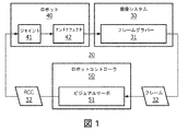
図1は、ロボット式システム20の1つの例示的な実施形態のブロック図である。
FIG. 1 is a block diagram of one exemplary embodiment of the
図1に図示されるように、ロボット式システム20は、撮像システム30と、ロボット40と、ロボットコントローラ50とを用いる。概して、ロボット式システム20は、ロボット40の自動的運動能力を伴う任意のロボット式処置のために構成される。このようなロボット式処置の例には、医療処置、組み立てライン処置、及び移動式ロボットを伴う処置があるが、これらに限定されない。特には、ロボット式システム20は、最小侵襲心臓手術(例えば、冠状動脈バイパス移植又は僧帽弁置換)、最小侵襲腹部手術(腹腔鏡検査)(例えば、前立腺切除又は胆嚢切除)、及び自然開口部越経管腔的内視鏡手術を含むがこれらに限定されない医療処置のために利用される。
As illustrated in FIG. 1, the robot-
ロボット40は、本明細書において、特定のロボット式処置のために所望されるロボット40のエンドエフェクタ42を操作するための1つ又は複数のジョイント41の電動制御を有するように構造的に構成された任意のロボット式デバイスとして広く定義される。エンドエフェクタ42は、グリッパ又はツールホルダを備える。エンドエフェクタ42は、腹腔鏡検査器具、腹腔鏡、脊椎固定手術におけるネジ設置のためのツール、生体検査若しくは治療のためのニードル、又は任意の他の手術若しくは介入ツールなどのツールを備える。
The
実際上は、ロボット40は、最小限で3つの自由度、有利には5つ又は6つの自由度を有する。ロボット40は、エンドエフェクタの軸と交差する2つのモータ軸を有する遠隔運動中心(RCM)機構を有する。有利には、ロボット40には、RCM機構の任意の軸に沿って光ビーム(例えば、レーザビーム)を投影するように構成された光投影装置(例えば、一対のレーザ)が関連付けられている。
In practice, the
エンドエフェクタ42の姿勢とは、ロボット40の座標系内でのエンドエフェクタ42の位置及び向きである。
The posture of the
撮像システム30は、1つ又は複数のカメラを含む。いくつかの実施形態において、撮像システム30は、回転3Dスキャンを生成するように構成された手術中X線システムを含む。撮像システムは、エンドエフェクタ42又はエンドエフェクタ42に保持されたツール(例えば、手術又は介入処置のためのもの)のための予定進入ポイント及びエンドエフェクタ42又はエンドエフェクタ42に保持されたツールのためのRCMを通る予定パスを含む手術フィールドにおけるロボット40のRCM機構の画像を撮影するように構成される。
The
撮像システム30は、フレームグラバー31も含むか、又はフレームグラバー31と関連付けられる。ロボット40は、ジョイント41(例えば、5つ又は6つのジョイント41)と、エンドエフェクタ42とを含む。以下により詳細に説明されるように、いくつかの実施形態において、エンドエフェクタ42は、ロボット40によって操作されるツールホルダとして構成される。ロボットコントローラ50は、以下により詳細に説明されるビジュアルサーボ51を含む。
The
撮像システム30は、前方光学視又は斜位光学視を有する任意のタイプのカメラであってよく、事前に定められたフレームレート(例えば、1秒当たり30フレーム)で一連の2次元的デジタルビデオフレーム32を取得することが可能で、各デジタルビデオフレーム32をロボットコントローラ50に提供することが可能な任意のタイプのフレームグラバー31を用いてよい。いくつかの実施形態では、フレームグラバー31は省かれることがあり、この場合、撮像システム30が、ロボットコントローラ50にその画像を送る。特には、撮像システム30は、その視野内でロボット40のエンドエフェクタ42及び遠隔運動中心(RCM)342の画像、及びRCM342がその内部で位置決め及び操作される動作空間の画像を撮影することができるように位置決め及び配向される。有利には、撮像システム30は、エンドエフェクタ42の姿勢を特定するために使用され得る既知の形状を有する基準オブジェクトの画像を撮影するようにも位置決めされる。いくつかの実施形態において、撮像システム30は、モータによって作動されるカメラを含み、以下により詳細に説明されるように、カメラは、撮像システム30が手術前画像に対してレジストレーションされたときにロボット40のための予定器具パスに沿って位置決めされ得る。
The
ロボットコントローラ50は、本明細書において、エンドエフェクタ42の所望の姿勢を達成するために必要な各ロボットジョイント41の決定的な移動を命令することによって、特定のロボット式処置のために所望されるエンドエフェクタ42の姿勢を制御するために、ロボット40に1つ又は複数のロボット制御コマンド(「RCC」)52を提供するように構造的に構成された任意のコントローラとして広く定義される。
The
例えば、ロボット制御コマンド52は、ロボット40のRCMを手術のための予定進入ポイントに対して位置合わせするために1つ又は複数のロボットジョイント41のセットを制御するため、及びエンドエフェクタ42を手術のための予定パスに対して位置合わせするために追加のロボットジョイントのペアを制御するために、撮像システム30による基準オブジェクト(例えば、エンドエフェクタ42)の追跡を容易にするために必要な1つ又は複数のロボットジョイント41を移動させる。
For example, the
デジタルビデオフレーム32内での画像の特徴のロボット式追跡のため、並びに、ロボット40をエンドエフェクタ42又はエンドエフェクタ42に保持されたツールのための予定進入ポイント及び予定パスに対して位置合わせ及び配向するために、ロボットコントローラ50は、RCMが予定進入ポイント及びパスに対して位置合わせ及び配向されたときに、各デジタルビデオフレーム32において特定された基準オブジェクトの画像及び画像上への基準オブジェクトの投影に対するエンドエフェクタ42の姿勢を、その既知の形状及び位置に基づいて、制御するためのビジュアルサーボ51を含む。
Alignment and orientation for robotic tracking of image features within the
このような目的で、図2に図示されるように、ビジュアルサーボ51は、フレームグラバー31によって実現される画像取得33とロボットジョイント41の制御された移動43とを伴う閉ロボット制御ループ21において、基準オブジェクト特定プロセス53と、向き設定プロセス55と、インバースキネマティクス(逆運動力学)プロセス57とを実現する。実際上は、プロセス53、55、及び57は、任意のプラットフォーム(例えば、一般的なコンピュータ、特定用途向け集積回路(ASIC)など)にインストールされたハードウェア、ソフトウェア、及び/又はファームウェアの任意の組み合わせによって具現化されるビジュアルサーボ51のモジュールによって実現されてよい。更には、プロセス53及び55は、ロボットコントローラ50の画像プロセッサによって実施されてよい。
For this purpose, as illustrated in FIG. 2, the
図2を参照すると、基準オブジェクト特定プロセス53は、当技術分野において知られている特徴認識アルゴリズムを使用してデジタルビデオフレーム32内で特定の基準オブジェクトを特定するための各デジタルビデオフレーム32の個別の処理を伴う。
Referring to FIG. 2, reference object identification process 53 is an individualization of each
再び図2を参照すると、基準オブジェクト特定プロセス53は、各デジタルビデオフレーム32内の基準オブジェクトを示す2次元的画像データ(「2DID」)54を生成し、向き設定プロセス55は、基準オブジェクトの向き又は形状を特定するために2Dデータ54を処理する。基準オブジェクトが認識される各デジタルビデオフレーム32について、向き設定プロセス55は、デジタルビデオフレーム32内の基準オブジェクトに対するロボット40のエンドエフェクタ42の所望の姿勢を示す3次元的ロボットデータ(「3DRD」)56を生成する。インバースキネマティクスプロセス57は、当技術分野において知られているように、ロボットジョイント41の適切なジョイント移動43のために必要な1つ又は複数のロボット制御コマンド52を生成し、それによって、デジタルビデオフレーム32内の基準オブジェクトに対するエンドエフェクタ42の所望の姿勢を達成するために、3Dデータ56を処理する。
Referring again to FIG. 2, the reference object identification process 53 generates two-dimensional image data (“2DID”) 54 indicating the reference object in each
動作においては、ロボットコントローラ50の画像プロセッサは、撮像システム30から撮影された画像を受信し、撮影された画像を3次元的(3D)手術前画像に対してレジストレーションし、投影された光ビーム(例えば、レーザビーム)を使用して撮影された画像においてRCMのための進入ポイント及びパスを定め、撮影された画像において基準オブジェクトを検知及び追跡する。更には、ロボットコントローラ50は、エンドエフェクタ42を予定進入ポイント及び予定パスに対して位置合わせするロボットジョイント運動パラメータを、定められた進入ポイント、定められたパス、及び検知された基準オブジェクトに応じて計算し、計算されたロボットジョイント運動パラメータに応じて、エンドエフェクタ42を予定進入ポイント及び予定パスに対して位置合わせするロボット制御コマンド52を生成し、ロボット制御コマンドをロボット40に通信する。
In operation, the image processor of the
次に、ロボット式システム20の様々なバージョンの更なる態様がより詳細に説明される。
Next, further aspects of the various versions of the
図3は、図1のロボット式システム20の第1のバージョンの一部分を示す。図3は、撮像デバイス、特にはカメラ330と、ロボット340とを図示する。ここで、カメラ330は撮像システム30の1つのバージョンであり、ロボット340はロボット40の1つのバージョンである。カメラ330は、その視野内でエンドエフェクタ42と遠隔運動中心(RCM)342とを含むロボット340の少なくとも一部分の画像、及びRCM342がその内部で位置決め及び操作される動作空間の画像を撮影することができるように位置決め及び配向される。図3には示されていないが、図3に示されるロボット式システムは、図1及び図2に関して上に記載されたロボットコントローラ50などのロボットコントローラを含むことが理解されるべきである。
FIG. 3 shows a portion of the first version of the
ロボット340は、5つのジョイントj1、j2、j3、j4、及びj5と、エンドエフェクタ360とを有する。ジョイントj1、j2、j3、j4、及びj5の各々は、ロボット340によってロボットコントローラ(例えば、ロボットコントローラ50)から受信された1つ又は複数のロボット制御コマンド52に応じてジョイントを操作することができる関連付けられたモータを有する。ジョイントj4及びj5はRCM342を定める。第1及び第2のレーザ512及び514は、対応するRCMレーザビーム513及び515を、それらがRCM342で交差するように投影する。いくつかの実施形態において、第1及び第2のレーザ512及び514は、ジョイントj4及びj5のモータ軸に沿ってRCMレーザビーム513及び515を投影する。図3に示されるような同心円弧システムを有する実施形態において、第1及び第2のレーザ512及び514は、円弧に沿った場所のどこに位置付けられてもよい。図には、予定パス115に沿った対象10のための予定進入ポイント15及び検知されたパス117に沿った検知された進入ポイント17も図示されている。
The
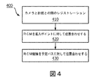
図4は、ロボット式システムによって実施されるロボットベースの誘導の方法400の1つの実施形態の主要な動作を示すフローチャートである。以下の説明において、具体的な例を提供するために、方法400は、図3に示されたバージョンのロボット式システム20によって実施されるものと仮定される。
FIG. 4 is a flowchart showing the main operation of one embodiment of the robot-based
動作410は、ロボット340のための計画(例えば、手術計画)とカメラ30とのレジストレーションを含む。ここで、ロボット340のための計画は、1つ又は複数の手術前3D画像に対して記述される。それ故、動作410において、カメラ300によって生成された画像(例えば、2D画像)は、例えば、フィリップスの特許出願(例えば、米国特許出願公開第2012/0294498(A1)号又はEP2615993B1)において説明されている方法などの当技術分野において知られているいくつかの方法を使用して手術前3D画像に対してレジストレーションされる。
Motion 410 includes registration of a plan for robot 340 (eg, a surgical plan) with
動作420は、予定進入ポイント15に対するロボット340のRCM342の位置合わせを含む。動作420の例示的な実施形態の更なる詳細は、図5に関して後述される。
The
動作430は、予定パス115に対するロボット340のRCM機構(例えば、ジョイントj4及びj5)の位置合わせを含む。動作430の例示的な実施形態の更なる詳細は、図6に関して後述される。
The operation 430 includes the alignment of the RCM mechanism (eg, joints j4 and j5) of the
図5は、方法400の動作420を実施する方法500の例示的な実施形態の詳細なステップを示すフローチャートである。ここで、手術前3D画像とカメラ300との間のレジストレーションのための動作410はすでに完了しているものと仮定される。
FIG. 5 is a flow chart showing detailed steps of an exemplary embodiment of
ステップ520において、画像プロセッサ又はロボットコントローラ50は、3D予定進入ポイント15を表す2Dポイントをカメラ330の撮影された画像(例えば、デジタルビデオフレーム32)上に投影する。カメラ330は対象10に対して移動していないので、投影された予定進入ポイント15は静的である。
In
ステップ530において、RCMレーザビーム513及び515の交差点は、検知された進入ポイント17を定めるために、カメラ330の撮影された画像において検知され得る。有利には、ロボット式システム及び方法500は、対象10への予定進入ポイント15が、通常、対象10の表面にあり、故に、カメラ330のビューによって可視化され得るとともに撮影された画像上に投影され得、一方、ロボット340のRCM342の現在の位置及び向きに対する検知された進入ポイント17を定めるために、レーザ512及び514から投影され得るレーザドットも撮影された画像において対象10上に視認可能であるという事実を利用し得る。
In step 530, the intersection of the
ステップ540において、ロボットコントローラ50は、RCMレーザビーム513及び515の交差点によって定められた進入ポイント17を予定進入ポイント15へと駆動するようにRCM342を移動させるために、ロボット340にロボット制御コマンド52を送る。いくつかの実施形態において、ステップ540は、米国特許第8,934,003(B2)号において説明されるアルゴリズムによって実施される。有利には、ステップ540は、ジョイントj1、j2、及びj3の移動を命令するロボット制御コマンド52によって実施される。有利には、定められた進入ポイント17が予定進入ポイント15に対して位置合わせされた後、ジョイントj1、j2、及びj3は、動作430を含む後続の動作のためにロックされる。
In
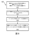
図6は、方法400の動作430を実施する方法600の例示的な実施形態の詳細なステップを示すフローチャートである。ここで、方法400及び方法500について上に記載されたように、手術前3D画像とカメラ300との間のレジストレーションのための動作はすでに完了しているものと仮定される。
FIG. 6 is a flow chart showing detailed steps of an exemplary embodiment of
ステップ610において、ロボットコントローラ50の画像処理サブシステムは、エンドエフェクタ42が予定器具パス115及び予定進入ポイント15に対して位置合わせされたときにカメラから見えるはずの基準オブジェクトの既知の形状をカメラ33の撮影された画像(例えば、デジタルビデオフレーム32)上に重畳又は投影する。以下の議論において、具体的な例を提供するために、基準オブジェクトはエンドエフェクタ42であると仮定される。しかしながら、一般的に、基準オブジェクトは、カメラ330の視野内の、既知の大きさ及び形状を有する任意のオブジェクト又は特徴であってよい。ここで、画像処理システムは、エンドエフェクタ42の形状及び大きさについて前もって情報を有しているものと仮定される。例えば、エンドエフェクタ42が円形状を有するならば、この形状は、カメラ330と、エンドエフェクタ42と、予定進入ポイント15との間の位置的/角度的な関係に応じて、カメラ330からは2次元的に楕円形状に見える。この場合、画像プロセッサは、エンドエフェクタ42が予定パス115に沿って予定進入ポイント15に対して位置合わせ及び配向されたときのエンドエフェクタ42のターゲット位置及び向きを表すターゲット楕円形状画像をカメラ330からの撮影された画像上に投影又は重畳する。更には、画像プロセッサは、エンドエフェクタ42の形状に依存するエンドエフェクタ42のターゲット楕円形状画像の他のパラメータ、例えば、円形状のエンドエフェクタ42の例示的な事例においては、投影された楕円形状の中心及び角度を定める。
In step 610, the image processing subsystem of the
ステップ620において、画像プロセッサは、撮影された画像におけるエンドエフェクタ42の画像を検知し、これをセグメント化する。
In
ステップ630において、画像プロセッサは、撮影された画像におけるエンドエフェクタ42の画像の形状を検知する。有利には、画像プロセッサは、撮影された画像におけるエンドエフェクタ42の検知された画像の他のパラメータを検知し、これらはエンドエフェクタ42の形状に依存する。例えば、エンドエフェクタ42が円形状を有するものと仮定すると、カメラ330の撮影された画像において楕円形状の画像を生み、次いでステップ630において、画像プロセッサは、撮影された画像32におけるエンドエフェクタ42の検知された画像の中心及び角度を検知する。
In
図7は、撮影された画像732の例及び撮影された画像732上のエンドエフェクタ42の例示的な投影された重畳部760を示す。ここで、投影された重畳部760は、エンドエフェクタ42が予定パス115に沿って予定進入ポイント15に対して位置合わせ及び配向されたときにエンドエフェクタ42がカメラ330の撮影された画像において有するはずの大きさ及び形状を表すものと仮定される。図7に図示される例において、エンドエフェクタ42の投影された重畳部760の中心7612は、エンドエフェクタ42の検知された画像の中心に対して位置合わせされているが、エンドエフェクタ42の投影された重畳部760とエンドエフェクタ42の検知された画像との間には回転角度7614が存在する。
FIG. 7 shows an example of the captured
この場合、ステップ640において、ロボットコントローラ50は、最適化アルゴリズムを実行してロボット40、及び、特には、ジョイントj4及びj5を備えるRCM機構を移動させ、カメラによって撮影されたエンドエフェクタ42の画像を投影された重畳部760に対して位置合わせする。エンドエフェクタ42の撮影された画像が投影された重畳部760に対して位置合わせされると、エンドエフェクタ42は、予定パス115に沿って予定進入ポイント15に対して位置合わせ及び配向される。
In this case, in
図8は、例えばロボット式システム20によって実行されるロボットベースの誘導の方法の動作において用いられるフィードバックループ800の1つの例示的な実施形態を示す。図8において、機能ブロックとしてフィードバックループ800の様々な操作子が示されている。フィードバックループ800は、コントローラ840、ロボット850、ツールセグメント化動作8510、中心検知動作8512、角度検知動作8514、及び処理動作8516を含む。ここで、フィードバックループ800は、楕円形状の投影を有する(例えば、円形状)基準オブジェクト(例えば、エンドエフェクタ42)とともに動作するように構成される。いくつかの場合において、ツールセグメント化動作8510、中心検知動作8512、角度検知動作8514、及び処理動作8516は、ロボットコントローラ50などのロボットコントローラによって、ハードウェア、ソフトウェア、ファームウェア、又はそれらの任意の組み合わせにおいて実施される。
FIG. 8 shows one exemplary embodiment of a
次に、フィードバックループ800の例示的な動作が説明される。
Next, an exemplary operation of the
処理動作8516は、エンドエフェクタ42の撮影された画像の検知された中心及び角度を、エンドエフェクタ42のターゲット角度及びターゲット中心から減算し、その結果、2つのエラー信号、すなわち中心エラー及び角度エラーがもたらされる。処理動作8516は、これらの2つのエラーを組み合わせ(例えば、これらに対応する重みを加算する)、重みづけられた組み合わせをフィードバック信号として、上述したロボットコントローラ50のコンポーネントとして含まれるコントローラ850に供給する。ここでコントローラ850は、比例−積分−微分(PID:proportional−integral−derivative)コントローラ、又はモデル予測コントローラなどの非線形コントローラを含む当技術分野において知られている任意の他の適切なコントローラであってよい。コントローラ850の出力は、RCM機構ジョイントベロシティのセットである。ジョイントベロシティへのマッピングは、ロボット840のエンドエフェクタ42のヨー及びピッチを撮影された画像のx及びy座標にマッピングすることによってなされ得る。エンドエフェクタ42の向きは、撮影された画像におけるエンドエフェクタ42の検知された形状と撮影された画像上への形状の平行投影との間の射影変換を使用してマッピングされ得る。
The
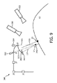
図9は、図1のロボット式システム20の第2のバージョンの一部分を示す。図9に示されるロボット式システム20の第2のバージョンは、図3に示されて上に詳述された第1のバージョンと構造及び動作において類似しており、従って、簡潔さのために、それらの間の相違点のみが説明される。
FIG. 9 shows a portion of a second version of the
ロボット式システム20の第2のバージョンにおいて、画像撮影システムは、既知の又は定められた構成において離間された少なくとも2つのカメラ330及び332を含む。カメラ330及び332の各々は、その視野内でエンドエフェクタ42とRCM342とを含むロボット340の少なくとも一部分の画像、及びRCM342がその内部で位置決め及び操作される動作空間の画像を撮影することができるように位置決め及び配向される。それ故、ロボット式システム20のこのバージョンにおいて、画像プロセッサは、各カメラ330及び332からの撮影された2D画像における基準オブジェクト(例えば、エンドエフェクタ42)を検知及び追跡し、撮影された2D画像からエンドエフェクタ42の3D形状を再構成するように構成される。
In a second version of the
ここで、撮影された画像の縮尺は、エンドエフェクタ42の既知の大きさ、及びカメラ330及び332の焦点距離を使用して再構成され得る。再構成された位置及び縮尺は、カメラ330及び332の座標フレームにおけるロボット340の3D位置を与える。エンドエフェクタ42の向きは、撮影された画像におけるエンドエフェクタ42の検知された形状と撮影された画像上への形状の平行投影との間の射影変換を使用して検知され得る。このバージョンは、3D空間におけるロボット340の位置を再構成し、ロボット構成空間をカメラ座標系に対してレジストレーションする。ロボット制御は位置ベースであり得、ロボットモータはロボットジョイント空間において移動されて、エンドエフェクタ42を初期位置及び向きから予定位置及び向きへと移動させる。
Here, the scale of the captured image can be reconstructed using the known size of the
ロボット式システム20の別のバージョンにおいて、RCM機構は、予定進入ポイント15を通るツール挿入軸の周りでエンドエフェクタ42を回転させることができるような追加的な自由度を備える。ここでも、エンドエフェクタ42は、挿入軸に垂直な平面内でその向きを定めるような特徴を備え、画像プロセッサは、撮影された画像においてこの特徴を検知し、特徴の予定位置を撮影された画像上に投影するように構成される。例えば、この特徴はピンを有した円形状又は矩形状でよい。ロボットコントローラ50は、検知された特徴と特徴の予定位置とが位置合わせされるようにロボット340を制御するように構成される。
In another version of the
このバージョンは、エンドエフェクタ42が回転対称でないとき、例えば、エンドエフェクタ42が把持具又は傾いたニードルであるときに有用であり得る。予定進入ポイント15及びパス115に沿ったエンドエフェクタ42の向きの両者が設定された後、エンドエフェクタ42は、特徴の予定位置と検知された位置とが位置合わせされるまで、追加的な自由度を使用して回転される。
This version can be useful when the
図10は、図1のロボット式システム20の第3のバージョンの一部分を示す。図10に示されるロボット式システム20の第3のバージョンは、図3に示されて上に詳述された第1のバージョンと構造及び動作において類似しており、従って、簡潔さのために、それらの間の相違点のみが説明される。
FIG. 10 shows a portion of a third version of the
ロボット式システム20の第3のバージョンにおいて、カメラ330は、予定パス115に沿って操作及び位置決めされ得るように、モータ1000によって作動される。ここでも、カメラ330は手術前画像に対してレジストレーションされるものと仮定される。図10に示された第3のバージョンの場合において、撮影された画像上へのエンドエフェクタ42の投影は、エンドエフェクタ42が予定パス115に沿って予定進入ポイント15に対して位置合わせ及び配向されたときの状況を反映して、平行投影となる。例えば、エンドエフェクタ42の形状が円形状であるなら、投影も円形状である。この場合、コントローラ50は、撮影された画像において平行投影が検知されるようにエンドエフェクタ42の位置を制御するように構成され得、これは一意解である。これは、RCM342が進入ポイント15に対して位置合わせされる前又は後になされ得る。もしも前になされたなら、RCM342は、予定重畳におけるエンドエフェクタ42の投影の中心と撮影された画像におけるエンドエフェクタ42の検知された位置とを位置合わせすることによって、位置決めされ得る。
In a third version of the
図11は、図10に示されたロボット式システムの第3のバージョンを使用してカメラ330によって撮影された一連のビデオフレームを使用した、円形状のロボットエンドエフェクタ42の、ロボットエンドエフェクタ42のための予定位置に対する位置合わせ及び配向のプロセスを示す。
FIG. 11 shows the
ここで、カメラ330によって撮影された第1の撮影されたビデオフレーム1132−1には、エンドエフェクタ42が予定パス115に沿って予定進入ポイント15に対して位置合わせ及び配向されたならばビデオフレーム1132−1において現れるはずのエンドエフェクタ42の投影1171が図示されている。しかしながら、代わりに、エンドエフェクタ42の検知された画像1161は、長軸11613及び短軸11615を有した楕円形状を有しており、投影1171の位置から横方向にずれている。
Here, the first captured video frame 11321 captured by the
カメラ330によって撮影された第2のフレーム1132−2には、エンドエフェクタの検知された画像1161が円形状を有するようにロボット40のRCM機構を制御するロボットコントローラ50によって実行される制御アルゴリズムの結果、エンドエフェクタ42の検知された画像1161がいまや円形状を有している様子が図示されている。しかしながら、第2のフレーム1132−2においては、検知された画像1161はいまだに投影1171の位置から横方向にずれており、投影1171よりも大きさが大きいことがわかる。
In the second frame 1132-2 taken by the
ビデオフレーム1132−2において描かれる状況になった後、ロボット340のRCM機構(例えば、ジョイントj4及びj5)はロックされてよく、位置決め機構はRCMを予定進入口に対して位置合わせするために移動される。 After the situation depicted in video frame 1132-2, the RCM mechanism of the robot 340 (eg, joints j4 and j5) may be locked and the positioning mechanism moves to align the RCM with respect to the planned entrance. Will be done.
両形状はいまや平行投影になっているので、このステップにおいて、例えば米国特許第8,934,003(B2)号に説明されている方法を使用して、図心が位置合わせされることだけが必要である。図心が位置合わせされたなら、縮尺が合わせられなければならない(検知されたエンドエフェクタ42の円の大きさを計画に従って投影されたエンドエフェクタ42の大きさに合わせる)。縮尺は、位置決め機構座標フレームにおいて計算され得るツールパス115に沿ったロボット40の運動によって定められる。
Since both shapes are now in parallel projection, the only step in this step is to align the centroids using, for example, the method described in US Pat. No. 8,934,003 (B2). is necessary. Once the centroids are aligned, the scale must be aligned (matching the size of the detected
カメラ330によって撮影された第3のフレーム1132−3には、エンドエフェクタ42の検知された画像1161が、いまや投影1171と位置合わせされた様子が図示されている。
The third frame 1132-3, photographed by the
図12は、ロボットベースの誘導の方法の動作において用いられる別のフィードバックループ1200の1つの例示的な実施形態を示す。図12は、例えばロボット式システム20によって実施されるロボットベースの誘導の方法の動作において用いられるフィードバックループ1200の1つの例示的な実施形態を示す。図12において、機能ブロックとしてフィードバックループ1200の様々な操作子が示されている。フィードバックループ1200は、コントローラ1240、ロボット1250、ツールセグメント化動作12510、長軸検知動作12513、短軸検知動作12515、及び処理動作12516を含む。ここで、フィードバックループ1200は、楕円形状の投影を有する(例えば、円形状)基準オブジェクト(例えば、エンドエフェクタ42)とともに動作するように構成される。いくつかの場合において、ツールセグメント化動作12510、長軸検知動作12513、短軸検知動作12515、及び処理動作12516は、ロボットコントローラ50などのロボットコントローラによって、ハードウェア、ソフトウェア、ファームウェア、又はそれらの任意の組み合わせにおいて実施される。
FIG. 12 shows one exemplary embodiment of another
次に、フィードバックループ1200の例示的な動作が説明される。
Next, an exemplary operation of the
処理動作12516は、エンドエフェクタ42の撮影された画像の検知された中心及び角度を、エンドエフェクタ42のターゲット角度及びターゲット中心から減算し、その結果、2つのエラー信号、すなわち中心エラー及び角度エラーがもたらされる。処理動作12516は、これらの2つのエラーを組み合わせ(例えば、これらに対応する重みを加算する)、重みづけられた組み合わせをフィードバック信号として、上述したロボットコントローラ50のコンポーネントとして含まれるコントローラ1250に供給する。ここでコントローラ1250は、比例−積分−微分(PID)コントローラ、又はモデル予測コントローラなどの非線形コントローラを含む当技術分野において知られている任意の他の適切なコントローラであってよい。コントローラ1250の出力は、RCM機構ジョイントベロシティのセットである。ジョイントベロシティへのマッピングは、ロボット1240のエンドエフェクタ42のヨー及びピッチを撮影された画像のx及びy座標にマッピングすることによってなされ得る。エンドエフェクタ42の向きは、撮影された画像におけるエンドエフェクタ42の検知された形状と撮影された画像上への形状の平行投影との間の射影変換を使用してマッピングされ得る。
The
図13は、図1のロボット式システム20の第4のバージョンの一部分を示す。図13に示されるロボット式システム20の第4のバージョンは、図3に示されて上に詳述された第1のバージョンと構造及び動作において類似しており、従って、簡潔さのために、それらの間の相違点のみが説明される。
FIG. 13 shows a portion of a fourth version of the
ロボット式システム20の第4のバージョンにおいて、カメラ330は、予定パス115が位置付けられる場所の回転3Dスキャンを生成するように構成された手術中X線システム1300に取り付けられている。
In a fourth version of the
ロボット式システム20の他のバージョンも可能である。特には、図3、図9、及び図10などに関して上に記載されたバージョンのうちの任意のものが、手術中X線システム1300を含むように修正されてよい。
Other versions of the
本明細書において、好ましい実施形態が詳細に開示されたが、本発明の概念及び範囲内に依然としてある多くの変形が可能である。このような変形は、本文書において明細書、図面及び特許請求の範囲を検証した後で、当業者には明らかになるであろう。従って、本発明は、添付の特許請求の範囲内にあることを除いては、限定されるものではない。 Although preferred embodiments have been disclosed in detail herein, many modifications still within the concepts and scope of the invention are possible. Such modifications will become apparent to those skilled in the art after examining the specification, drawings and claims in this document. Therefore, the present invention is not limited except that it is within the scope of the appended claims.
Claims (20)
前記RCMで交差する2つ以上の光ビームを投影する光投影装置と、
予定進入ポイントと前記RCMを通る予定パスとを含む手術フィールドにおける前記RCM機構の画像を撮影する撮像システムと、
前記ロボットを制御し、前記RCM機構を位置決めするロボットコントローラであって、前記撮像システムから撮影された画像を受信し、前記撮影された画像を3次元的手術前画像に対してレジストレーションし、投影された光ビームを使用して前記撮影された画像において前記RCMに対する進入ポイント及びパスを定め、前記撮影された画像において、前記エンドエフェクタと関連付けられる、既知の形状を有する基準オブジェクトを検知及び追跡する画像プロセッサを含む前記ロボットコントローラと、を含み、
前記ロボットコントローラは、前記エンドエフェクタを前記予定進入ポイント及び前記予定パスに対して位置合わせするロボットジョイント運動パラメータを、定められた進入ポイント、定められたパス、及び検知された基準オブジェクトに応じて計算し、計算されたロボットジョイント運動パラメータに基づいて、前記エンドエフェクタを前記予定進入ポイント及び前記予定パスに対して位置合わせするロボット制御コマンドを生成し、前記ロボット制御コマンドを前記ロボットに通信し、
前記ロボットコントローラは、前記撮影された画像における前記基準オブジェクトの1つ又は複数の幾何学的パラメータを決定し、前記基準オブジェクトが当該基準オブジェクトの予定位置に位置付けられるときに前記撮像システムに現れるように、前記撮影された画像における前記基準オブジェクトの前記1つ又は複数の幾何学的パラメータを、既知の対応する前記基準オブジェクトの1つ又は複数の幾何学的パラメータに対して位置合わせすることによって、前記ロボットジョイント運動パラメータを計算する、システム。 A robot having a remote center of motion (RCM) mechanism having two motor axes and an end effector provided at the distal end of the robot.
An optical projection device that projects two or more light beams that intersect at the RCM, and
An imaging system that captures an image of the RCM mechanism in a surgical field that includes a planned approach point and a planned path through the RCM.
A robot controller that controls the robot and positions the RCM mechanism, receives an image captured from the imaging system, registers the captured image with respect to a three-dimensional preoperative image, and projects the captured image. has been using a light beam define the entry points and the path for the RCM in the captured image, in the captured image, associated with the end effector, for detecting and tracking a reference object having a known shape Including the robot controller, which includes an image processor,
The robot controller calculates robot joint motion parameters that align the end effector with respect to the planned approach point and the planned path according to the defined approach point, the defined path, and the detected reference object. Then, based on the calculated robot joint motion parameters, a robot control command for aligning the end effector with respect to the planned approach point and the planned path is generated, and the robot control command is communicated with the robot.
The robot controller determines one or more geometric parameters of the reference object in the captured image so that the reference object appears in the imaging system when it is positioned at the planned position of the reference object. By aligning the one or more geometric parameters of the reference object in the captured image with respect to one or more known corresponding geometric parameters of the reference object. A system that calculates robot joint motion parameters.
予定進入ポイントと前記RCMを通る予定パスとを含む手術フィールドにおける前記RCM機構の画像を撮影するステップと、
撮影された前記画像を3次元的(3D)手術前画像に対してレジストレーションするステップと、
投影された光ビームを使用して前記撮影された画像において前記RCMのための進入ポイント及びパスを定めるステップと、
前記撮影された画像において、前記エンドエフェクタと関連付けられる、既知の形状を有する基準オブジェクトを検知及び追跡するステップと、
前記進入ポイント、前記パス、及び前記基準オブジェクトについての情報に応じて、前記エンドエフェクタを前記予定進入ポイント及び前記予定パスに対して位置合わせするロボットジョイント運動パラメータを計算するステップと、
計算された前記ロボットジョイント運動パラメータに基づいて、前記エンドエフェクタを前記予定進入ポイント及び前記予定パスに対して位置合わせするロボット制御コマンドをロボットに通信するステップと、を有する、方法であって、
前記ロボットジョイント運動パラメータを計算するステップは、前記撮影された画像における前記基準オブジェクトの1つ又は複数の幾何学的パラメータを決定し、前記基準オブジェクトが当該基準オブジェクトの予定位置に位置付けられるときに撮像システムに現れるように、前記撮影された画像における前記基準オブジェクトの前記1つ又は複数の幾何学的パラメータを、既知の対応する前記基準オブジェクトの1つ又は複数の幾何学的パラメータに対して位置合わせするステップを含む、方法。 A step of providing at least two intersecting light beams in an RCM defined by a remote center of motion (RCM) mechanism of a robot with an end effector at the distal end.
A step of taking an image of the RCM mechanism in a surgical field including a planned entry point and a planned path through the RCM.
A step of registering the captured image with respect to a three-dimensional (3D) preoperative image,
Steps to determine the entry point and path for the RCM in the captured image using the projected light beam, and
A step of detecting and tracking a reference object having a known shape associated with the end effector in the captured image.
A step of calculating robot joint motion parameters for aligning the end effector with respect to the planned approach point and the planned path, depending on information about the approach point, the path, and the reference object.
A method comprising: communicating a robot control command to the robot to position the end effector with respect to the planned approach point and the planned path based on the calculated robot joint motion parameters .
The step of calculating the robot joint motion parameters determines one or more geometric parameters of the reference object in the captured image and images the reference object when it is positioned at the planned position of the reference object. Aligning the one or more geometric parameters of the reference object in the captured image with respect to one or more known corresponding geometric parameters of the reference object so as to appear in the system. A method that includes steps to do .
を有する、請求項9に記載の方法。 A step of detecting the approach point as an intersection of the projected light beams, a step of controlling the robot so that the intersection of the projected light beams is aligned with the planned approach point, and a step of controlling the robot.
9. The method of claim 9.
前記撮影された画像における検知された前記基準オブジェクトが投影された既知の形状と重畳するよう前記にロボットを制御するステップと、
を有する、請求項9に記載の方法。 A step of projecting the known shape of the reference object at the planned position onto the captured image, and
And controlling the robot to the to the reference objects detected in the captured image is superimposed with the known shape projected,
9. The method of claim 9.
前記複数のカメラの各々から撮影された2D画像における既知の形状を有する前記基準オブジェクトを検知及び追跡するステップと、
前記撮影された2D画像から前記基準オブジェクトの3D形状を再構成するステップと、
を有する、請求項9に記載の方法。 A step of capturing a two-dimensional (2D) image of the RCM mechanism in the surgical field from multiple cameras spaced apart in a known configuration.
A step of detecting and tracking the reference object having a known shape in a 2D image taken from each of the plurality of cameras.
A step of reconstructing the 3D shape of the reference object from the captured 2D image,
9. The method of claim 9.
前記撮影された画像において前記特徴を検知するステップと、
前記特徴の予定位置を撮影された画像上に投影するステップと、
検知された前記特徴と予定位置とが位置合わせされるように前記ロボットを制御するステップと、
を有する、請求項9に記載の方法。 A step of rotating the end effector around an insertion axis passing through the planned entry point, wherein the end effector is characterized in that it is oriented in a plane perpendicular to the insertion axis.
The step of detecting the feature in the captured image and
The step of projecting the planned position of the feature on the captured image and
A step of controlling the robot so that the detected feature and the planned position are aligned with each other.
9. The method of claim 9.
前記撮影された画像において前記エンドエフェクタの平行投影が検知されるように前記エンドエフェクタの位置を制御するステップと、を有する、請求項9に記載の方法。 A step of capturing an image of the RCM mechanism using a camera positioned along the planned path, wherein the reference object is the end effector.
The method according to claim 9, further comprising a step of controlling the position of the end effector so that parallel projection of the end effector is detected in the captured image.
前記ロボットコントローラは、前記RCMで交差する2つ以上の光ビームを投影して撮影された画像であって、予定進入ポイント及びRCMを通る予定パスを含む手術フィールドにおける前記RCM機構の撮影された画像を受信し、前記撮影された画像を3次元的(3D)手術前画像に対してレジストレーションし、前記撮影された画像において前記RCMに対する進入ポイント及びパスを定め、前記撮影された画像において、前記エンドエフェクタと関連付けられる、既知の形状を有する基準オブジェクトを検知及び追跡する画像プロセッサと、ロボット制御コマンドを前記ロボットに通信するロボット制御コマンドインターフェースと、を備え、
前記ロボットコントローラは、前記エンドエフェクタを前記予定進入ポイント及び前記予定パスに対して位置合わせするロボットジョイント運動パラメータを、定められた前記進入ポイント、定められたパス、及び検知された前記基準オブジェクトに応じて計算する計算されたロボットジョイント運動パラメータに基づいて、前記エンドエフェクタを前記予定進入ポイント及び前記予定パスに対して位置合わせするロボット制御コマンドを生成し、
前記ロボットコントローラは、前記撮影された画像における前記基準オブジェクトの1つ又は複数の幾何学的パラメータを決定し、前記基準オブジェクトが当該基準オブジェクトの予定位置に位置付けられるときに撮像システムに現れるように、前記撮影された画像における前記基準オブジェクトの前記1つ又は複数の幾何学的パラメータを、既知の対応する前記基準オブジェクトの1つ又は複数の幾何学的パラメータに対して位置合わせすることによって、前記ロボットジョイント運動パラメータを計算する、ロボットコントローラ。 A robot controller for controlling a robot having a remote center of motion (RCM) mechanism having two motor axes and an end effector provided at the distal end.
The robot controller is an image taken by projecting two or more light beams intersecting at the RCM, and is an image taken by the RCM mechanism in a surgical field including a planned approach point and a planned path through the RCM. receives, the resist configure the captured image to the three-dimensional (3D) preoperative image, define the entry points and the path for the RCM in the captured image, in the captured image, wherein It includes an image processor that detects and tracks a reference object with a known shape associated with an end effector, and a robot control command interface that communicates robot control commands to the robot.
The robot controller sets robot joint motion parameters that align the end effector with respect to the planned approach point and the planned path according to the defined entry point, the defined path, and the detected reference object. Based on the calculated robot joint motion parameters calculated in the above, a robot control command for aligning the end effector with respect to the planned approach point and the planned path is generated.
The robot controller determines one or more geometric parameters of the reference object in the captured image so that the reference object appears in the imaging system when it is positioned at the planned position of the reference object. The robot by aligning the one or more geometric parameters of the reference object in the captured image with respect to one or more known geometric parameters of the corresponding reference object. A robot controller that calculates joint motion parameters.
Applications Claiming Priority (3)
| Application Number | Priority Date | Filing Date | Title |
|---|---|---|---|
| US201562272737P | 2015-12-30 | 2015-12-30 | |
| US62/272,737 | 2015-12-30 | ||
| PCT/IB2016/057863 WO2017115227A1 (en) | 2015-12-30 | 2016-12-21 | Image based robot guidance |
Publications (3)
| Publication Number | Publication Date |
|---|---|
| JP2019502462A JP2019502462A (en) | 2019-01-31 |
| JP2019502462A5 JP2019502462A5 (en) | 2020-02-06 |
| JP6912481B2 true JP6912481B2 (en) | 2021-08-04 |
Family
ID=57838433
Family Applications (1)
| Application Number | Title | Priority Date | Filing Date |
|---|---|---|---|
| JP2018533939A Active JP6912481B2 (en) | 2015-12-30 | 2016-12-21 | Image-based robot guidance |
Country Status (5)
| Country | Link |
|---|---|
| US (1) | US20200261155A1 (en) |
| EP (1) | EP3397187A1 (en) |
| JP (1) | JP6912481B2 (en) |
| CN (1) | CN108601626A (en) |
| WO (1) | WO2017115227A1 (en) |
Families Citing this family (13)
| Publication number | Priority date | Publication date | Assignee | Title |
|---|---|---|---|---|
| US11033341B2 (en) | 2017-05-10 | 2021-06-15 | Mako Surgical Corp. | Robotic spine surgery system and methods |
| EP3621545B1 (en) | 2017-05-10 | 2024-02-21 | MAKO Surgical Corp. | Robotic spine surgery system |
| US11432877B2 (en) * | 2017-08-02 | 2022-09-06 | Medtech S.A. | Surgical field camera system that only uses images from cameras with an unobstructed sight line for tracking |
| WO2019148428A1 (en) * | 2018-02-01 | 2019-08-08 | Abb Schweiz Ag | Vision-based operation for robot |
| CN109223176B (en) * | 2018-10-26 | 2021-06-25 | 中南大学湘雅三医院 | Operation planning system |
| EP3824839A1 (en) * | 2019-11-19 | 2021-05-26 | Koninklijke Philips N.V. | Robotic positioning of a device |
| KR102278149B1 (en) * | 2020-01-08 | 2021-07-16 | 최홍희 | Multipurpose laser pointing-equipment for medical |
| RU2753118C2 (en) * | 2020-01-09 | 2021-08-11 | Федеральное государственное автономное образовательное учреждение высшего образования "Севастопольский государственный университет" | Robotic system for holding and moving surgical instrument during laparoscopic operations |
| JP7459234B2 (en) * | 2020-04-10 | 2024-04-01 | 川崎重工業株式会社 | Medical mobile system and its operating method |
| CN112932669B (en) * | 2021-01-18 | 2024-03-15 | 广州市微眸医疗器械有限公司 | Mechanical arm control method for executing retina layer anti-seepage tunnel |
| CN113687627B (en) * | 2021-08-18 | 2022-08-19 | 太仓中科信息技术研究院 | Target tracking method based on camera robot |
| CN113766083B (en) * | 2021-09-09 | 2024-05-14 | 思看科技(杭州)股份有限公司 | Parameter configuration method of tracking scanning system, electronic device and storage medium |
| CN117103286B (en) * | 2023-10-25 | 2024-03-19 | 杭州汇萃智能科技有限公司 | Manipulator eye calibration method and system and readable storage medium |
Family Cites Families (13)
| Publication number | Priority date | Publication date | Assignee | Title |
|---|---|---|---|---|
| US6187018B1 (en) * | 1999-10-27 | 2001-02-13 | Z-Kat, Inc. | Auto positioner |
| AU2002343552B2 (en) * | 2001-11-08 | 2006-04-27 | The Johns Hopkins University | System and method for robot targeting under flouroscopy based on image servoing |
| US8428689B2 (en) * | 2007-06-12 | 2013-04-23 | Koninklijke Philips Electronics N.V. | Image guided therapy |
| US20110071541A1 (en) * | 2009-09-23 | 2011-03-24 | Intuitive Surgical, Inc. | Curved cannula |
| JP5814938B2 (en) | 2010-01-08 | 2015-11-17 | コーニンクレッカ フィリップス エヌ ヴェKoninklijke Philips N.V. | Calibration-free visual servo using real-time speed optimization |
| CN102711650B (en) | 2010-01-13 | 2015-04-01 | 皇家飞利浦电子股份有限公司 | Image integration based registration and navigation for endoscopic surgery |
| DE102010029275A1 (en) * | 2010-05-25 | 2011-12-01 | Siemens Aktiengesellschaft | Method for moving an instrument arm of a Laparoskopierobotors in a predetermined relative position to a trocar |
| WO2012035492A1 (en) | 2010-09-15 | 2012-03-22 | Koninklijke Philips Electronics N.V. | Robotic control of an endoscope from blood vessel tree images |
| KR20140090374A (en) * | 2013-01-08 | 2014-07-17 | 삼성전자주식회사 | Single port surgical robot and control method thereof |
| GB201303917D0 (en) * | 2013-03-05 | 2013-04-17 | Ezono Ag | System for image guided procedure |
| WO2015118422A1 (en) * | 2014-02-04 | 2015-08-13 | Koninklijke Philips N.V. | Remote center of motion definition using light sources for robot systems |
| KR102237597B1 (en) * | 2014-02-18 | 2021-04-07 | 삼성전자주식회사 | Master device for surgical robot and control method thereof |
| DE102014209368A1 (en) * | 2014-05-16 | 2015-11-19 | Siemens Aktiengesellschaft | Magnetic resonance imaging system and method for assisting a person in positioning a medical instrument for percutaneous intervention |
-
2016
- 2016-12-21 JP JP2018533939A patent/JP6912481B2/en active Active
- 2016-12-21 US US16/066,079 patent/US20200261155A1/en not_active Abandoned
- 2016-12-21 CN CN201680080556.3A patent/CN108601626A/en active Pending
- 2016-12-21 WO PCT/IB2016/057863 patent/WO2017115227A1/en active Application Filing
- 2016-12-21 EP EP16828779.5A patent/EP3397187A1/en not_active Withdrawn
Also Published As
| Publication number | Publication date |
|---|---|
| JP2019502462A (en) | 2019-01-31 |
| CN108601626A (en) | 2018-09-28 |
| US20200261155A1 (en) | 2020-08-20 |
| WO2017115227A1 (en) | 2017-07-06 |
| EP3397187A1 (en) | 2018-11-07 |
Similar Documents
| Publication | Publication Date | Title |
|---|---|---|
| JP6912481B2 (en) | Image-based robot guidance | |
| CN109069217B (en) | System and method for pose estimation in image-guided surgery and calibration of fluoroscopic imaging system | |
| US8971597B2 (en) | Efficient vision and kinematic data fusion for robotic surgical instruments and other applications | |
| US9066737B2 (en) | Method for moving an instrument arm of a laparoscopy robot into a predeterminable relative position with respect to a trocar | |
| JP2018110873A (en) | Collision avoidance during controlled movement of image capturing device and manipulatable device movable arms | |
| US20230000565A1 (en) | Systems and methods for autonomous suturing | |
| Zhang et al. | Autonomous scanning for endomicroscopic mosaicing and 3D fusion | |
| KR20080027256A (en) | Method and system for performing 3-d tool tracking by fusion of sensor and/or camera derived data during minimally invasive robotic surgery | |
| Zhan et al. | Autonomous tissue scanning under free-form motion for intraoperative tissue characterisation | |
| CN114650785A (en) | Robotic positioning of a device | |
| KR20240021747A (en) | Medical robots for ultrasound-guided needle placement | |
| Nageotte et al. | Visual servoing-based endoscopic path following for robot-assisted laparoscopic surgery | |
| Molnár et al. | Visual servoing-based camera control for the da Vinci Surgical System | |
| Marmol et al. | ArthroSLAM: Multi-sensor robust visual localization for minimally invasive orthopedic surgery | |
| Heunis et al. | Collaborative surgical robots: Optical tracking during endovascular operations | |
| Piccinelli et al. | Rigid 3D registration of pre-operative information for semi-autonomous surgery | |
| Vitrani et al. | Robust ultrasound-based visual servoing for beating heart intracardiac surgery | |
| Krupa et al. | Autonomous retrieval and positioning of surgical instruments in robotized laparoscopic surgery using visual servoing and laser pointers | |
| Wang et al. | Image-based trajectory tracking control of 4-DOF laparoscopic instruments using a rotation distinguishing marker | |
| EP4284287A1 (en) | Multi-arm robotic systems for identifying a target | |
| US11596567B2 (en) | Systems and methods for determining and maintaining a center of rotation | |
| US20220241032A1 (en) | Multi-arm robotic systems and methods for identifying a target | |
| US20210259779A1 (en) | Multi-camera user interface device calibration and tracking | |
| US20240070875A1 (en) | Systems and methods for tracking objects crossing body wallfor operations associated with a computer-assisted system | |
| Yang et al. | Design and development of an augmented reality robotic system for large tumor ablation |
Legal Events
| Date | Code | Title | Description |
|---|---|---|---|
| A521 | Written amendment |
Free format text: JAPANESE INTERMEDIATE CODE: A523 Effective date: 20191219 |
|
| A621 | Written request for application examination |
Free format text: JAPANESE INTERMEDIATE CODE: A621 Effective date: 20191219 |
|
| A977 | Report on retrieval |
Free format text: JAPANESE INTERMEDIATE CODE: A971007 Effective date: 20201228 |
|
| A131 | Notification of reasons for refusal |
Free format text: JAPANESE INTERMEDIATE CODE: A131 Effective date: 20210222 |
|
| A521 | Written amendment |
Free format text: JAPANESE INTERMEDIATE CODE: A523 Effective date: 20210518 |
|
| TRDD | Decision of grant or rejection written | ||
| A01 | Written decision to grant a patent or to grant a registration (utility model) |
Free format text: JAPANESE INTERMEDIATE CODE: A01 Effective date: 20210609 |
|
| A61 | First payment of annual fees (during grant procedure) |
Free format text: JAPANESE INTERMEDIATE CODE: A61 Effective date: 20210708 |
|
| R150 | Certificate of patent or registration of utility model |
Ref document number: 6912481 Country of ref document: JP Free format text: JAPANESE INTERMEDIATE CODE: R150 |