JP6907247B2 - Medical navigation system using optical position sensing and how to operate it - Google Patents
Medical navigation system using optical position sensing and how to operate it Download PDFInfo
- Publication number
- JP6907247B2 JP6907247B2 JP2018568808A JP2018568808A JP6907247B2 JP 6907247 B2 JP6907247 B2 JP 6907247B2 JP 2018568808 A JP2018568808 A JP 2018568808A JP 2018568808 A JP2018568808 A JP 2018568808A JP 6907247 B2 JP6907247 B2 JP 6907247B2
- Authority
- JP
- Japan
- Prior art keywords
- view
- ultrasonic probe
- information
- orientation
- views
- Prior art date
- Legal status (The legal status is an assumption and is not a legal conclusion. Google has not performed a legal analysis and makes no representation as to the accuracy of the status listed.)
- Active
Links
Images


Classifications
-
- A—HUMAN NECESSITIES
- A61—MEDICAL OR VETERINARY SCIENCE; HYGIENE
- A61B—DIAGNOSIS; SURGERY; IDENTIFICATION
- A61B8/00—Diagnosis using ultrasonic, sonic or infrasonic waves
- A61B8/42—Details of probe positioning or probe attachment to the patient
- A61B8/4245—Details of probe positioning or probe attachment to the patient involving determining the position of the probe, e.g. with respect to an external reference frame or to the patient
- A61B8/4254—Details of probe positioning or probe attachment to the patient involving determining the position of the probe, e.g. with respect to an external reference frame or to the patient using sensors mounted on the probe
-
- A—HUMAN NECESSITIES
- A61—MEDICAL OR VETERINARY SCIENCE; HYGIENE
- A61B—DIAGNOSIS; SURGERY; IDENTIFICATION
- A61B34/00—Computer-aided surgery; Manipulators or robots specially adapted for use in surgery
- A61B34/25—User interfaces for surgical systems
-
- A—HUMAN NECESSITIES
- A61—MEDICAL OR VETERINARY SCIENCE; HYGIENE
- A61B—DIAGNOSIS; SURGERY; IDENTIFICATION
- A61B34/00—Computer-aided surgery; Manipulators or robots specially adapted for use in surgery
- A61B34/20—Surgical navigation systems; Devices for tracking or guiding surgical instruments, e.g. for frameless stereotaxis
-
- A—HUMAN NECESSITIES
- A61—MEDICAL OR VETERINARY SCIENCE; HYGIENE
- A61B—DIAGNOSIS; SURGERY; IDENTIFICATION
- A61B8/00—Diagnosis using ultrasonic, sonic or infrasonic waves
- A61B8/12—Diagnosis using ultrasonic, sonic or infrasonic waves in body cavities or body tracts, e.g. by using catheters
-
- A—HUMAN NECESSITIES
- A61—MEDICAL OR VETERINARY SCIENCE; HYGIENE
- A61B—DIAGNOSIS; SURGERY; IDENTIFICATION
- A61B8/00—Diagnosis using ultrasonic, sonic or infrasonic waves
- A61B8/42—Details of probe positioning or probe attachment to the patient
- A61B8/4245—Details of probe positioning or probe attachment to the patient involving determining the position of the probe, e.g. with respect to an external reference frame or to the patient
- A61B8/4263—Details of probe positioning or probe attachment to the patient involving determining the position of the probe, e.g. with respect to an external reference frame or to the patient using sensors not mounted on the probe, e.g. mounted on an external reference frame
-
- A—HUMAN NECESSITIES
- A61—MEDICAL OR VETERINARY SCIENCE; HYGIENE
- A61B—DIAGNOSIS; SURGERY; IDENTIFICATION
- A61B8/00—Diagnosis using ultrasonic, sonic or infrasonic waves
- A61B8/46—Ultrasonic, sonic or infrasonic diagnostic devices with special arrangements for interfacing with the operator or the patient
- A61B8/461—Displaying means of special interest
- A61B8/463—Displaying means of special interest characterised by displaying multiple images or images and diagnostic data on one display
-
- A—HUMAN NECESSITIES
- A61—MEDICAL OR VETERINARY SCIENCE; HYGIENE
- A61B—DIAGNOSIS; SURGERY; IDENTIFICATION
- A61B8/00—Diagnosis using ultrasonic, sonic or infrasonic waves
- A61B8/52—Devices using data or image processing specially adapted for diagnosis using ultrasonic, sonic or infrasonic waves
- A61B8/5215—Devices using data or image processing specially adapted for diagnosis using ultrasonic, sonic or infrasonic waves involving processing of medical diagnostic data
- A61B8/5223—Devices using data or image processing specially adapted for diagnosis using ultrasonic, sonic or infrasonic waves involving processing of medical diagnostic data for extracting a diagnostic or physiological parameter from medical diagnostic data
-
- G—PHYSICS
- G16—INFORMATION AND COMMUNICATION TECHNOLOGY [ICT] SPECIALLY ADAPTED FOR SPECIFIC APPLICATION FIELDS
- G16H—HEALTHCARE INFORMATICS, i.e. INFORMATION AND COMMUNICATION TECHNOLOGY [ICT] SPECIALLY ADAPTED FOR THE HANDLING OR PROCESSING OF MEDICAL OR HEALTHCARE DATA
- G16H20/00—ICT specially adapted for therapies or health-improving plans, e.g. for handling prescriptions, for steering therapy or for monitoring patient compliance
- G16H20/40—ICT specially adapted for therapies or health-improving plans, e.g. for handling prescriptions, for steering therapy or for monitoring patient compliance relating to mechanical, radiation or invasive therapies, e.g. surgery, laser therapy, dialysis or acupuncture
-
- G—PHYSICS
- G16—INFORMATION AND COMMUNICATION TECHNOLOGY [ICT] SPECIALLY ADAPTED FOR SPECIFIC APPLICATION FIELDS
- G16H—HEALTHCARE INFORMATICS, i.e. INFORMATION AND COMMUNICATION TECHNOLOGY [ICT] SPECIALLY ADAPTED FOR THE HANDLING OR PROCESSING OF MEDICAL OR HEALTHCARE DATA
- G16H30/00—ICT specially adapted for the handling or processing of medical images
- G16H30/40—ICT specially adapted for the handling or processing of medical images for processing medical images, e.g. editing
-
- G—PHYSICS
- G16—INFORMATION AND COMMUNICATION TECHNOLOGY [ICT] SPECIALLY ADAPTED FOR SPECIFIC APPLICATION FIELDS
- G16H—HEALTHCARE INFORMATICS, i.e. INFORMATION AND COMMUNICATION TECHNOLOGY [ICT] SPECIALLY ADAPTED FOR THE HANDLING OR PROCESSING OF MEDICAL OR HEALTHCARE DATA
- G16H50/00—ICT specially adapted for medical diagnosis, medical simulation or medical data mining; ICT specially adapted for detecting, monitoring or modelling epidemics or pandemics
- G16H50/30—ICT specially adapted for medical diagnosis, medical simulation or medical data mining; ICT specially adapted for detecting, monitoring or modelling epidemics or pandemics for calculating health indices; for individual health risk assessment
-
- A—HUMAN NECESSITIES
- A61—MEDICAL OR VETERINARY SCIENCE; HYGIENE
- A61B—DIAGNOSIS; SURGERY; IDENTIFICATION
- A61B17/00—Surgical instruments, devices or methods, e.g. tourniquets
- A61B17/00234—Surgical instruments, devices or methods, e.g. tourniquets for minimally invasive surgery
- A61B2017/00238—Type of minimally invasive operation
- A61B2017/00243—Type of minimally invasive operation cardiac
-
- A—HUMAN NECESSITIES
- A61—MEDICAL OR VETERINARY SCIENCE; HYGIENE
- A61B—DIAGNOSIS; SURGERY; IDENTIFICATION
- A61B34/00—Computer-aided surgery; Manipulators or robots specially adapted for use in surgery
- A61B34/20—Surgical navigation systems; Devices for tracking or guiding surgical instruments, e.g. for frameless stereotaxis
- A61B2034/2046—Tracking techniques
- A61B2034/2051—Electromagnetic tracking systems
-
- A—HUMAN NECESSITIES
- A61—MEDICAL OR VETERINARY SCIENCE; HYGIENE
- A61B—DIAGNOSIS; SURGERY; IDENTIFICATION
- A61B34/00—Computer-aided surgery; Manipulators or robots specially adapted for use in surgery
- A61B34/20—Surgical navigation systems; Devices for tracking or guiding surgical instruments, e.g. for frameless stereotaxis
- A61B2034/2046—Tracking techniques
- A61B2034/2061—Tracking techniques using shape-sensors, e.g. fiber shape sensors with Bragg gratings
-
- A—HUMAN NECESSITIES
- A61—MEDICAL OR VETERINARY SCIENCE; HYGIENE
- A61B—DIAGNOSIS; SURGERY; IDENTIFICATION
- A61B34/00—Computer-aided surgery; Manipulators or robots specially adapted for use in surgery
- A61B34/25—User interfaces for surgical systems
- A61B2034/254—User interfaces for surgical systems being adapted depending on the stage of the surgical procedure
-
- A—HUMAN NECESSITIES
- A61—MEDICAL OR VETERINARY SCIENCE; HYGIENE
- A61B—DIAGNOSIS; SURGERY; IDENTIFICATION
- A61B34/00—Computer-aided surgery; Manipulators or robots specially adapted for use in surgery
- A61B34/25—User interfaces for surgical systems
- A61B2034/256—User interfaces for surgical systems having a database of accessory information, e.g. including context sensitive help or scientific articles
-
- A—HUMAN NECESSITIES
- A61—MEDICAL OR VETERINARY SCIENCE; HYGIENE
- A61B—DIAGNOSIS; SURGERY; IDENTIFICATION
- A61B34/00—Computer-aided surgery; Manipulators or robots specially adapted for use in surgery
- A61B34/30—Surgical robots
- A61B2034/301—Surgical robots for introducing or steering flexible instruments inserted into the body, e.g. catheters or endoscopes
-
- A—HUMAN NECESSITIES
- A61—MEDICAL OR VETERINARY SCIENCE; HYGIENE
- A61B—DIAGNOSIS; SURGERY; IDENTIFICATION
- A61B90/00—Instruments, implements or accessories specially adapted for surgery or diagnosis and not covered by any of the groups A61B1/00 - A61B50/00, e.g. for luxation treatment or for protecting wound edges
- A61B90/08—Accessories or related features not otherwise provided for
- A61B2090/0818—Redundant systems, e.g. using two independent measuring systems and comparing the signals
-
- A—HUMAN NECESSITIES
- A61—MEDICAL OR VETERINARY SCIENCE; HYGIENE
- A61B—DIAGNOSIS; SURGERY; IDENTIFICATION
- A61B90/00—Instruments, implements or accessories specially adapted for surgery or diagnosis and not covered by any of the groups A61B1/00 - A61B50/00, e.g. for luxation treatment or for protecting wound edges
- A61B90/36—Image-producing devices or illumination devices not otherwise provided for
- A61B2090/364—Correlation of different images or relation of image positions in respect to the body
- A61B2090/365—Correlation of different images or relation of image positions in respect to the body augmented reality, i.e. correlating a live optical image with another image
-
- A—HUMAN NECESSITIES
- A61—MEDICAL OR VETERINARY SCIENCE; HYGIENE
- A61B—DIAGNOSIS; SURGERY; IDENTIFICATION
- A61B90/00—Instruments, implements or accessories specially adapted for surgery or diagnosis and not covered by any of the groups A61B1/00 - A61B50/00, e.g. for luxation treatment or for protecting wound edges
- A61B90/36—Image-producing devices or illumination devices not otherwise provided for
- A61B90/37—Surgical systems with images on a monitor during operation
- A61B2090/378—Surgical systems with images on a monitor during operation using ultrasound
-
- A—HUMAN NECESSITIES
- A61—MEDICAL OR VETERINARY SCIENCE; HYGIENE
- A61B—DIAGNOSIS; SURGERY; IDENTIFICATION
- A61B90/00—Instruments, implements or accessories specially adapted for surgery or diagnosis and not covered by any of the groups A61B1/00 - A61B50/00, e.g. for luxation treatment or for protecting wound edges
- A61B90/39—Markers, e.g. radio-opaque or breast lesions markers
- A61B2090/3966—Radiopaque markers visible in an X-ray image
-
- A—HUMAN NECESSITIES
- A61—MEDICAL OR VETERINARY SCIENCE; HYGIENE
- A61B—DIAGNOSIS; SURGERY; IDENTIFICATION
- A61B8/00—Diagnosis using ultrasonic, sonic or infrasonic waves
- A61B8/56—Details of data transmission or power supply
- A61B8/565—Details of data transmission or power supply involving data transmission via a network
Landscapes
- Health & Medical Sciences (AREA)
- Life Sciences & Earth Sciences (AREA)
- Engineering & Computer Science (AREA)
- Medical Informatics (AREA)
- Public Health (AREA)
- Surgery (AREA)
- General Health & Medical Sciences (AREA)
- Nuclear Medicine, Radiotherapy & Molecular Imaging (AREA)
- Biomedical Technology (AREA)
- Veterinary Medicine (AREA)
- Animal Behavior & Ethology (AREA)
- Heart & Thoracic Surgery (AREA)
- Molecular Biology (AREA)
- Radiology & Medical Imaging (AREA)
- Pathology (AREA)
- Biophysics (AREA)
- Physics & Mathematics (AREA)
- Epidemiology (AREA)
- Primary Health Care (AREA)
- Robotics (AREA)
- Urology & Nephrology (AREA)
- Databases & Information Systems (AREA)
- Data Mining & Analysis (AREA)
- Human Computer Interaction (AREA)
- Physiology (AREA)
- Computer Vision & Pattern Recognition (AREA)
- Ultra Sonic Daignosis Equipment (AREA)
Description
本発明のシステムは、光学的形状感知(optical−shape−sensing:OSS)法などの形状感知法を使用して外科的介入中に外科用器具の追跡を実行する医療用ナビゲーション・システムに関し、より詳細には、Fiber Optic RealShape(商標)(FORS)追跡法を使用して外科的介入中に外科用器具を追跡する医療用ナビゲーション・システム、及びその操作方法に関する。 The system of the present invention relates to a medical navigation system that performs tracking of surgical instruments during a surgical intervention using shape sensing methods such as optical-shape-sensing (OSS). More specifically, it relates to a medical navigation system that tracks surgical instruments during a surgical intervention using the Faber Optical RealShape ™ (FORS) tracking method, and how to operate it.
患者などの物体の解剖学的構造を超音波を使用して画像化するための最適な位置及びビューを見つけることは難しく、外科的介入などの手技中ではなおさらである。例えば、器質的心疾患手技などの手技中には、超音波プローブの一型である経食道エコー(TEE)プローブが、患者の心臓の特定のビューが得られるような態様で配置される。しかしながら、TEEプローブによる2つ以上のビューが望ましいことがあり、そのためには、臨床医が、それらのビューに対する他の所望の位置及び/又は向きまでTEEプローブを操作し、それらのそれぞれのビューに対する超音波パラメータを調整することが必要となる。残念なことに、TEEプローブの位置及び/又は向きを操作すること並びに超音波パラメータを変更することは、特に外科的介入中に貴重な時間を消費することになる。さらに、時間の浪費に加えて、手技中に以前のビューに戻ることは、不可能ではないとしてもしばしば困難である。したがって、優れた超音波臨床医であっても、外科的介入中にTEEプローブを用いて作業することは難しいと感じる。 It is difficult to find the optimal location and view for imaging the anatomy of an object such as a patient using ultrasound, especially during procedures such as surgical intervention. For example, during procedures such as organic heart disease procedures, transesophageal echo (TEE) probes, a type of ultrasound probe, are placed in a manner that provides a specific view of the patient's heart. However, two or more views with TEE probes may be desirable, for which the clinician manipulates the TEE probes to other desired positions and / or orientations relative to those views and for each of those views. It is necessary to adjust the ultrasonic parameters. Unfortunately, manipulating the position and / or orientation of the TEE probe and changing ultrasonic parameters consumes valuable time, especially during surgical intervention. Moreover, in addition to wasting time, returning to the previous view during the procedure is often difficult, if not impossible. Therefore, even a good ultrasound clinician finds it difficult to work with a TEE probe during a surgical intervention.
したがって、本発明のシステムの実施形態は、従来の画像化システムのこれらの欠点及びその他の欠点を解決する。 Therefore, embodiments of the system of the present invention solve these and other drawbacks of conventional imaging systems.
本明細書に記載されたシステム、装置、方法、配置、ユーザ・インタフェース、コンピュータ・プログラム、プロセスなど(以後、コンテキストに反しない限り、これらはそれぞれシステムと呼ばれる)は、先行技術のシステムの課題に対処する。本発明のシステムの実施形態は、形状感知位置合せ法を使用する。この方法は、同時サンプル点の不連続セット又は連続体とみなされるものなどのサンプル点を使用し、これらのサンプル点は、異なる座標系が位置合せされるように、座標系の位置に関する情報を提供する。 The systems, devices, methods, arrangements, user interfaces, computer programs, processes, etc. described herein (these are referred to as systems, respectively, unless contrary to context) are the challenges of prior art systems. deal with. Embodiments of the system of the present invention use the shape-sensing alignment method. This method uses sample points, such as a discontinuous set of simultaneous sample points or what is considered a continuum, and these sample points provide information about the position of the coordinate system so that different coordinate systems are aligned. offer.
本発明のシステムの実施形態によれば、本発明のシステムの一態様として、外科用誘導システムが開示される。この外科用誘導システムは、メモリと、表現装置と、超音波プローブと、超音波プローブに関連づけられた形状感知装置(SSD、shape-sensing-device)であって超音波プローブに対して所定の位置及び向きを有する形状感知装置(SSD)と、メモリ、表現装置及びSSDに結合されたコントローラとを含み、コントローラは、超音波プローブの場所と向きのうちの少なくとも一方を、SSDから受信した位置センサ情報(PSI)に基づいて決定し、メモリに記憶されたワークフローの複数のビューの中から1つのビューを選択し、選択されたビューに対するビュー設定情報(VSI)であって、それぞれのビューに対する超音波プローブの位置及び向きのうちの少なくとも一方とパラメータとを含むVSIをメモリから取得し、超音波プローブの決定された場所及び向きと選択されたビューに対する超音波プローブの位置及び向きのうちの少なくとも一方との比較に基づいて、誘導情報を決定し、決定された誘導情報を表現装置上に表現し、選択されたビューに対するVSIのパラメータに基づいて超音波プローブ・パラメータを設定するように構成されている。 According to an embodiment of the system of the present invention, a surgical guidance system is disclosed as one aspect of the system of the present invention. This surgical guidance system is a memory, an expression device, an ultrasonic probe, and a shape-sensing-device (SSD) associated with the ultrasonic probe, which is in a predetermined position with respect to the ultrasonic probe. A position sensor that includes a shape-sensing device (SSD) with a and orientation, a memory, a representation device, and a controller coupled to the SSD, the controller receiving at least one of the location and orientation of the ultrasonic probe from the SSD. Select one view from multiple views of the workflow determined based on information (PSI) and stored in memory, and the view setting information (VSI) for the selected view, which is the ultrasound for each view. The VSI containing at least one of the positions and orientations of the ultrasonic probe and the parameters is obtained from memory, and at least one of the positions and orientations of the ultrasonic probe with respect to the determined location and orientation of the ultrasonic probe and the selected view. It is configured to determine guidance information based on comparison with one, represent the determined guidance information on a representation device, and set ultrasonic probe parameters based on the VSI parameters for the selected view. ing.
本発明のシステムの実施形態によれば、SSDは、少なくとも1つの位置センサを備えていてもよく、コントローラは、少なくとも1つの位置センサに問い合わせてPSIを取得するように構成されていてもよく、PSIは、ワークスペース(workspace)に対する少なくとも1つの位置センサの位置及び向きのうちの少なくとも一方を示す。さらに、コントローラがさらに、決定された誘導情報を、選択されたビューに対する超音波プローブの位置及び向きのうちの少なくとも一方まで超音波プローブを誘導するための方向指示として表現するように構成されることが想定される。コントローラはさらに、ワークフローの複数のビューのうちの2つ以上のビューを表現装置上に同時に表示するように構成されていてもよい。コントローラはさらに、2つ以上のそれぞれのビューに対する指示を表現装置上に表示するように構成されていてもよい。コントローラがさらに、2つ以上のビューを、2つ以上のビューが解剖学的に配置された単一のビューとして表現装置上に表示するように構成されることも想定される。 According to embodiments of the system of the invention, the SSD may include at least one position sensor and the controller may be configured to query at least one position sensor to obtain PSI. The PSI indicates at least one of the positions and orientations of at least one position sensor relative to the workspace. In addition, the controller is further configured to represent the determined guidance information as turn signals to guide the ultrasonic probe to at least one of the position and orientation of the ultrasonic probe with respect to the selected view. Is assumed. The controller may also be configured to simultaneously display two or more views of the workflow views on the representation device. The controller may also be configured to display instructions for each of the two or more views on the representation device. It is also envisioned that the controller is configured to display the two or more views on the representation device as a single view in which the two or more views are anatomically arranged.
本発明のシステムの実施形態によれば、設定された超音波プローブ・パラメータを使用して超音波画像情報を取得するために、コントローラが、超音波プローブの少なくとも1つの変換器に結合されていてもよい。さらに、コントローラがさらに、設定された超音波プローブ・パラメータに従う超音波画像情報に基づいて画像を再構成するように構成されることが想定される。コントローラはさらに、選択されたビューに関連した超音波プローブの現在のパラメータ、場所、向き及び超音波情報のうちの2つ以上を関連づけて、記憶するように構成されていてもよい。コントローラがさらに、複数のビューのうちのどのビューが、決定された超音波プローブの場所及び向きのうちの少なくとも一方に最も近いのかを判定し、最も近いと判定されたビューに基づいてそのビューを選択するように構成されることも想定される。 According to an embodiment of the system of the present invention, a controller is coupled to at least one converter of the ultrasound probe to obtain ultrasound image information using the configured ultrasound probe parameters. May be good. Further, it is envisioned that the controller is further configured to reconstruct the image based on the ultrasound image information according to the configured ultrasound probe parameters. The controller may also be configured to associate and store two or more of the current parameters, location, orientation and ultrasonic information of the ultrasonic probe associated with the selected view. The controller further determines which of the multiple views is closest to at least one of the determined ultrasound probe locations and orientations, and based on the view determined to be the closest. It is also expected to be configured to be selected.
本発明のシステムの実施形態によればさらに、超音波情報を取得するために超音波プローブを誘導する方法が開示される。この方法は、少なくとも1つのコントローラによって実行され、超音波プローブの場所及び向きのうちの少なくとも一方を位置センサ情報(PSI)に基づいて決定するステップと、メモリに記憶されたワークフローの複数のビューの中から1つのビューを選択するステップと、選択されたビューに対するビュー設定情報(VSI)であって、それぞれのビューに対する超音波プローブの位置及び向きのうちの少なくとも一方とパラメータとに関する情報を含むVSIを取得するステップと、超音波プローブの場所及び向きと選択されたビューに対する超音波プローブの位置及び向きのうちの少なくとも一方との比較に基づいて、誘導情報を決定するステップと、決定された誘導情報を出力し、選択されたビューに対するVSIのパラメータに基づいて超音波プローブ・パラメータを設定するステップとを有する。この方法はさらに、形状感知装置(SSD)の少なくとも1つの位置センサに問い合わせてPSIを取得するステップを含んでもよく、PSIは、ワークスペースに対する少なくとも1つの位置センサの位置及び向きのうちの少なくとも一方を示す。 Further, according to an embodiment of the system of the present invention, a method of guiding an ultrasonic probe to acquire ultrasonic information is disclosed. This method is performed by at least one controller to determine at least one of the location and orientation of the ultrasound probe based on position sensor information (PSI) and multiple views of the workflow stored in memory. A VSI that includes the step of selecting one view from among and the view configuration information (VSI) for the selected view, including information about at least one of the positions and orientations of the ultrasonic probe for each view and the parameters. And the step of determining the guidance information based on the comparison of the location and orientation of the ultrasonic probe with at least one of the position and orientation of the ultrasonic probe with respect to the selected view, and the determined guidance. It has a step of outputting information and setting ultrasonic probe parameters based on VSI parameters for the selected view. The method may further include querying at least one position sensor on the shape sensing device (SSD) to obtain PSI, where the PSI is at least one of the positions and orientations of at least one position sensor with respect to the workspace. Is shown.
さらに、決定された誘導情報を出力するステップが、決定された誘導情報に対応する誘導命令を生成するステップ、及び生成された誘導命令をシステムの表現装置上に表現するステップを含むことが想定される。決定された誘導情報を出力するステップは、超音波プローブの位置及び向きのうちの少なくとも一方を制御するために、誘導情報を少なくとも1つのロボット・アクチュエータに送信するステップを含んでもよい。出力するステップが、決定された誘導情報を、選択されたビューに対する超音波プローブの位置及び向きのうちの少なくとも一方まで超音波プローブを誘導するための方向指示として出力するステップを含むことも想定される。さらに、この方法が、ワークフローの複数のビューのうちの2つ以上のビューを表現装置上に同時に表示するステップを含むことが想定される。 Further, it is assumed that the step of outputting the determined guidance information includes a step of generating a guidance instruction corresponding to the determined guidance information and a step of expressing the generated guidance instruction on the expression device of the system. NS. The step of outputting the determined guidance information may include the step of transmitting the guidance information to at least one robot actuator in order to control at least one of the position and orientation of the ultrasonic probe. It is also envisioned that the output step comprises outputting the determined guidance information as a turn signal to guide the ultrasonic probe to at least one of the position and orientation of the ultrasonic probe with respect to the selected view. NS. Further, it is envisioned that this method includes the step of simultaneously displaying two or more views of a plurality of views of the workflow on the representation device.
本発明のシステムの別の態様では、ユーザ・インタフェースが、決定されたVSI若しくはプローブ・パラメータ又はワークフローの選択に対応する誘導命令及び誘導情報を提示する。 In another aspect of the system of the present invention, the user interface presents guidance instructions and guidance corresponding to a determined VSI or probe parameter or workflow selection.
本発明のシステムの実施形態によればさらに、コンピュータ命令を含む非一時的コンピュータ可読媒体が開示される。このコンピュータ命令は、プロセッサによって実行されたときに、超音波プローブの場所及び向きのうちの少なくとも一方を位置センサ情報(PSI)に基づいて決定するステップと、ワークフローの位置合せされた少なくとも1つのビューの中から1つのビューを選択するステップと、選択されたビューに対するビュー設定情報(VSI)であり、位置合せされたそれぞれのビューに対するパラメータ及びそれぞれのビューに対する超音波プローブの位置及び向きのうちの少なくとも一方に関する情報を含むVSIを取得するステップと、超音波プローブの場所及び向きと選択されたビューに対する超音波プローブの位置及び向きのうちの少なくとも一方との比較に基づいて、誘導情報を決定するステップと、決定された誘導情報を出力し、選択されたビューに対するVSIのパラメータに基づいて超音波プローブ・パラメータを設定するステップとをプロセッサが実施。このコンピュータ命令が、形状感知装置(SSD)の少なくとも1つの位置センサに問い合わせてPSIを取得するステップをプロセッサが実施し、PSIが、ワークスペースに対する少なくとも1つの位置センサの位置及び向きのうちの少なくとも一方を示すことも想定される。さらに、このコンピュータ命令が、ワークフローの複数のビューのうちの2つ以上のビューを同時に表示するステップを実行するようにプロセッサを構成することが想定される。さらに、このコンピュータ命令によって、プロセッサが、複数のビューのうちの2つ以上のビューを、2つ以上のビューが解剖学的に配置された単一のビューとして同時に表示するステップを実行するように構成されてもよい。 Further, according to an embodiment of the system of the present invention, a non-transitory computer-readable medium including computer instructions is disclosed. This computer instruction, when executed by the processor, determines at least one of the location and orientation of the ultrasound probe based on position sensor information (PSI) and at least one aligned view of the workflow. The step of selecting one view from the list, the view setting information (VSI) for the selected view, the parameters for each aligned view, and the position and orientation of the ultrasonic probe for each view. Guidance information is determined based on a step of obtaining a VSI containing information about at least one and a comparison of the location and orientation of the ultrasonic probe with at least one of the position and orientation of the ultrasonic probe with respect to the selected view. The processor performs a step and a step of outputting the determined guidance information and setting the ultrasonic probe parameters based on the VSI parameters for the selected view. The computer instruction causes the processor to perform a step of querying at least one position sensor on the shape sensing device (SSD) to obtain PSI, and the PSI will perform at least one of the positions and orientations of at least one position sensor with respect to the workspace. It is also expected to show one. Further, it is envisioned that this computer instruction configures the processor to perform a step of simultaneously displaying two or more views of a plurality of views of the workflow. In addition, this computer instruction causes the processor to perform the step of simultaneously displaying two or more of the views as a single view in which the two or more views are anatomically arranged. It may be configured.
以下の例示的な実施形態では、図を参照して本発明をさらに詳細に説明する。それらの図では、同一の要素又は類似の要素が、部分的に、同じ参照符号又は類似の参照符号によって示されている。さまざまな例示的な実施形態の特徴は組み合わせることができる。 In the following exemplary embodiments, the invention will be described in more detail with reference to the figures. In those figures, the same or similar elements are partially represented by the same or similar reference codes. The features of various exemplary embodiments can be combined.
以下の説明は、図面とともに検討したときに上述の特徴及び利点並びに追加の特徴及び利点を示す例示的な実施形態の説明である。以下の説明では、限定のためではなく説明のために、アーキテクチャ、インタフェース、技法、要素属性などの例示的な詳細が示される。しかしながら、当業者には、それらの詳細から逸脱する他の実施形態も添付の特許請求の範囲に含まれることが依然として理解されることが明らかである。さらに、分かりやすくするため、本発明のシステムの説明を不明瞭にすることがないように、よく知られている装置、回路、ツール、技法及び方法の詳細な説明は省かれている。図面は、例示のために含まれているのであって、本発明のシステムの完全な範囲を表すものではないことを特に理解すべきである。添付図面では、異なる図面の同様の参照符号が同様の要素を示していることがある。用語「及び/又は」等は、特許請求の範囲及び本発明のシステムの1つ又は複数の実施形態に従って、(例えば、列挙された1つの要素だけが存在する、列挙された要素のうちの2つの要素が存在する、列挙された全ての要素が存在するなど)列挙された要素のうちの1つ又は複数の要素だけがシステム内に適切に存在すればよいことを意味すると理解すべきである。 The following description is an exemplary embodiment showing the features and advantages described above as well as additional features and benefits when considered with the drawings. In the following description, exemplary details such as architecture, interfaces, techniques, element attributes, etc. are provided for illustration purposes, not for limitation. However, it will be apparent to those skilled in the art that other embodiments that deviate from those details are still included in the appended claims. Further, for clarity, detailed description of well-known devices, circuits, tools, techniques and methods has been omitted so as not to obscure the description of the system of the present invention. It should be especially understood that the drawings are included for illustration purposes only and do not represent the full scope of the system of the invention. In the accompanying drawings, similar reference numerals in different drawings may indicate similar elements. The terms "and / or" etc. are used according to the claims and one or more embodiments of the system of the invention (eg, two of the listed elements in which only one listed element is present). It should be understood that it means that only one or more of the listed elements need to be properly present in the system (one element exists, all the listed elements exist, etc.). ..
次に、分かりやすくするため、FORS法などを使用して利用される形状感知ファイバなどの形状感知装置(SSD)に関して本発明のシステムの実施形態を示し、説明する。しかしながら、本発明のシステムの実施形態が、多数のデータ点を逐次的に又は同時にサンプリングするEM追跡法などの他の追跡システムと両立することも想定される。さらに、本発明のシステムのSSDは単独で使用され、又はカテーテルなどのシース、ガイドワイヤ、外科用器具、画像化用器具(例えば超音波プローブ)などと一緒に使用されると考えるべきである。 Next, for the sake of clarity, an embodiment of the system of the present invention will be described and described with respect to a shape sensing device (SSD) such as a shape sensing fiber used by using the FORS method or the like. However, it is also envisioned that embodiments of the system of the present invention will be compatible with other tracking systems, such as the EM tracking method, which samples a large number of data points sequentially or simultaneously. In addition, the SSDs of the systems of the invention should be considered to be used alone or in conjunction with sheaths such as catheters, guide wires, surgical instruments, imaging instruments (eg, ultrasound probes) and the like.
図1は、本発明のシステムの実施形態に従って動作する超音波医療用ナビゲーション・システム100(以後、分かりやすくするためシステム100と称する)の一部分の正面斜視図を示す。システム100は、SSD102、超音波プローブ104、ベース108、支持プラットホーム110、コントローラ122、ロボット・コントローラ140、ネットワーク120、メモリ124、センサ132及びユーザ・インタフェース(UI)126のうちの1つ又は複数を含む。コントローラ122は、システム100の全体動作を制御し、SSD102、超音波プローブ104、ベース108、支持プラットホーム110、メモリ124、センサ132、ロボット・コントローラ140及びUI126のうちの1つ又は複数と、適当な有線及び/又は無線通信法を使用して通信する。例えば、コントローラ122は、ネットワーク120を介して超音波プローブ104と通信する。ロボット・コントローラ140は、超音波プローブ104などの本発明のシステムの1つ又は複数の外科用器具を、所望の位置及び/又は向きまでロボットにより操作するように動作可能である。これに応じて、ロボット・コントローラ140は、1つ若しくは複数の軸(例えば7つなど多数の軸)に沿って又は1つ若しくは複数の軸の周りで超音波プローブ140を操作するために、1つ又は複数のアクチュエータ、アームなどを含む。
FIG. 1 shows a front perspective view of a part of an ultrasonic medical navigation system 100 (hereinafter referred to as a
ネットワーク120は、ワイドエリア・ネットワーク(WAN)、ローカルエリア・ネットワーク(LAN)、インターネット、システム・バス、プロプリエタリ・バス、インターネット、イントラネット、有線バス、無線バスなど、適当な通信リンクを含む。これに応じて、ユーザは、局所及び/又は遠隔通信法を使用してシステムと通信する。メモリ124は、オペレーティング命令などの情報、システムによって生成された情報、ユーザ入力及び/又は設定、履歴情報、オペレーティング設定及び/又はパラメータ、識別情報、ユーザ情報、患者情報などが記憶された適当な不揮発性メモリを含む。
センサ132は、対応するセンサ情報を取得し、そのセンサ情報をさらなる処理のためにコントローラ122に提供するセンサを含む。コントローラ122は、センサ情報に関して1つ又は複数のセンサ132に問い合わせる。例えば、センサ132は、SSD102の形状を感知し、その情報をコントローラ122に提供する光学的形状センサを含み、コントローラ122は、本発明のシステムの実施形態に従ってSSD102の1つ又は複数の部分の位置及び/又は向きを決定する。センサ132は、システム100の全体にわたって分布しており、センサ132はさらに、それを用いてユーザがシステムに情報を入力するタッチ・センサ、キーボードなどのセンサを含む。センサ132はさらにEM追跡センサを含む。さらに、センサ132は、台110、患者101、ベース108、EM追跡装置などの位置/向きに関する位置/向き情報を提供する位置センサを含む。
The
UI126は、システムによって生成されたグラフィカル・ユーザ・インタフェース(GUI)及び/又は画像情報などユーザの便益のための情報を表現する適当なユーザ・インタフェースを含む。これに応じて、UI126は、スピーカ(SPK)、ディスプレイ128(例えばタッチスクリーン・ディスプレイなど)、触覚装置(例えばバイブレータなど)を含んでもよい。支持プラットホーム110は、介入手技などの手技のために患者101などの物体を所望の位置及び/又は向きに支持する適当な支持プラットホームである。支持プラットホーム110は、コントローラ122の制御の下で支持プラットホームを移動させるアクチュエータを含んでもよい。
The
ベース108は、超音波プローブ104及びSSD102のうちの1つ又は複数のための発出固定具として機能する(物理的な又は仮想の)1つ又は複数の適当な装置ベースを含む。これに応じて、超音波プローブ104及びSSD102のうちの1つ又は複数の少なくとも一部分の位置及び/又は向きが、基準フレーム105に対して決定される。ベース108は複数のベースを含んでもよい。基準フレーム105は、支持プラットホーム110の基準フレーム、患者101の基準フレーム、共通基準フレームなど、適当な基準フレームを含む。しかしながら、分かりやすくするため、基準フレーム105は患者101の基準フレームを指すと仮定する。このようにすると、基準フレーム105は、患者101の解剖学的構造に対応する。これに応じて、システム100は、分かりやすくするために患者101によって画定されたワークスペースを使用する。このワークスペースを患者ワークスペースと呼ぶ。ベース108は、Cアーム、支持プラットホーム110などの適当な固定具に結合されている。
The
超音波プローブ104は、実行されている手技のための適当な超音波プローブを含む。例えば、本発明の実施形態では、超音波プローブ104が、1つ又は複数のビュー(例えばビューポイント)に対する患者101の心臓の画像を構成するための超音波画像情報を取得する経食道エコー(TEE)プローブを含むと仮定する。さらに、超音波プローブ104の位置、向き、設定及び/又はパラメータはビューごとに異なると仮定する。超音波プローブ104は、それぞれのビューに対する超音波画像情報を捕捉するための超音波センサ(例えば変換器)アレイ106を含む。超音波センサ・アレイ106は、超音波プローブ104の遠位端107に位置し、又は遠位端107に隣接して位置する。超音波プローブ104は、例えば超音波プローブ104の一部分、例えば超音波センサ・アレイ106の位置及び/又は向きが容易に決定されるようにSSD102を受け取るのに適した開口を含む。しかしながら、限定はされないが、要望に応じて、この開口は、SSD102の一部分を受け取るのに適した切欠き又はタブを含んでもよいことを理解すべきである。この切欠き又はタブは、超音波プローブ104の遠位端107又は遠位端107の近くなど、超音波プローブ104上の所望の位置に配置される。この開口は、開口に対するSSD102の位置及び向きが規定されるような態様でSSD102を受け取るように構成される。例えば、この開口は、超音波プローブ104に対するSSD102の位置及び/又は向きが決定されるような単一の位置でだけSSD102を受け取るように調節される。SSD102の位置及び/又は向きは、位置及び/又は向きベクトルを使用して決定される。しかしながら、他の実施形態では、超音波プローブ104が、SSD102から既知の距離のところに固定される(例えば図3〜図6を参照されたい)。
The
超音波プローブ104は、シース105の遠位端に配置される。シース105は、その長さに沿って1つ又は複数の開口を含み、この開口を通して、SSD102が、超音波プローブ104に到達するために挿入される。同様に、超音波プローブ104も、同じ開口又は別の開口を通して挿入される。したがって、超音波プローブ104とSSD102は、シース105内に同時に配置される。しかしながら、他の実施形態によれば、超音波プローブ104とSSD104が異なる管孔を通して挿入される。
The
超音波プローブ104は、適当な有線及び/又は無線通信法を使用してコントローラ122と通信する。例えば、超音波プローブ104は、ネットワーク120を介してコントローラ122と通信する。コントローラ122は、所望のビュー(例えば所望のビューポイント)の超音波画像を生成するのに適した超音波情報を生成するように超音波センサ・アレイ106を制御する。超音波プローブ104は、X線画像などのシステムの1つ又は複数の画像の中で認識される識別ランドマークを含み、超音波プローブ104の対応する位置及び/又は向きが決定される。その後に、超音波プローブ104から取得された画像をX線画像などに対して位置合せする位置合せが実行され、超音波プローブ104のX線画像に基づいて、超音波プローブ104の位置及び/又は向きが決定される。適当な位置合せ法は、X線と超音波との位置合せを示している米国特許出願公開第2012/0245458号、並びにFORSと超音波との位置合せを示している国際特許公開第WO2014/053934A1号及びFORSとX線との位置合せを示している同第WO2015010859号の中で論じられている。これらのそれぞれの文献の内容は参照によって本明細書に組み込まれている。すぐに理解されることだが、他の適当な画像位置合せ法も、本発明のシステムの部分の位置合せに適当に適用される。
The
SSD102は、患者101の基準フレーム(例えば患者ワークスペース)などの所望の基準フレームに対するSSD102の少なくとも一部分の位置及び/又は向きを決定するのに適したSSD情報を提供する少なくとも1つのセンサを含む。分かりやすくするため、SSD102は、SSD102の遠位端103が超音波プローブ104のところに位置するような態様で超音波プローブ104の開口の少なくとも一部分を通過すると仮定される。例えば、SSD102は超音波プローブに結合されている。しかしながら、他の実施形態では、希望する場合に、超音波プローブ104から既知の距離のところにSSD102が位置し、超音波プローブ102の位置及び/又は向きを決定するために、既知のオフセット距離及び/又は向きが使用される。SSD102はさらに、(例えばベース108に既知の位置及び/又は向きで結合された)既知の経路111などの既知の経路を通過し又は既知の経路内にあり、その既知の経路が、位置合せのためにシステム100によって認識される。超音波プローブ104は既知の経路を含み、例えば、その結果、超音波プローブ104がこの既知の経路内に位置しているときに、この既知の経路が(例えばSSD情報を解析することによって)認識され、超音波プローブ104の位置及び/若しくは向き、又は超音波プローブ104の部分の位置及び/若しくは向き、例えば超音波プローブ104のこの既知の形状のところの部分の位置又は超音波プローブ104のこの既知の形状に隣接する部分の位置及び/若しくは向きが決定される。
The
コントローラ122を再び参照する。コントローラ122は、システム100の全体動作を制御し、プロセッサ130(例えばマイクロプロセッサ(μP)など)などの1つ又は複数の論理装置を含み、この論理装置は、トランジスタ、ゲート、インピーダンス装置、メタライゼーション接続など、離散及び/若しくは分散型の論理ゲート及びスイッチング装置、並びに/又は他の同様の装置などの相互接続された多数の半導体装置を有する。コントローラ122は、問合せモジュール134及び/又は位置合せモジュール136を含み、これらのモジュールは、ハードウェア、ソフトウェア及び/又はファームウェア装置を含み、これらの装置は、そのメモリ及び/又はメモリ124に記憶された命令を有し、これらの命令は、プロセッサによって実行されたときに、1つ又は複数の所望の機能をプロセッサに実行させる。
Refer to
問合せモジュール134は、時間の経過に伴ってSSD102が移動する経路及び/又はSSD102の1つ若しくは複数の部分の形状を示すSSD情報(SSDI)(後述)などの情報を(例えば問合せプロセスを介して)SSD102から取得するように動作可能である。この経路は、逐次的に(例えば経時的に)及び/又は同時に(例えば一時に)決定される。次いで、超音波プローブ104の場所及び/又は向きを決定するためにSSDIが処理される。既知の経路又は1つ若しくは複数の既知の経路(例えば111)を通して、又は既知の経路又は1つ若しくは複数の既知の経路(例えば111)内にSSDが配置されているとき、SSDは、対応する1つ又は複数の既知の経路の形状を呈し、対応するSSDIを形成する。コントローラ122は、この既知の経路を(例えばSSDIを解析することによって)認識し、この対応して認識された既知の経路に対するSSD102の1つ又は複数の部分の位置及び/又は向きを決定する。しかしながら、このSSDIに基づいて、既知の経路(例えば超音波プローブ104内の既知の経路)の位置及び/又は向きが決定されることも想定される。
The
位置合せモジュール136は、この実施形態で使用される患者101のワークスペース(例えば患者101の解剖学的構造を反映した患者ワークスペース)などの1つ又は複数の基準座標系に対して、SSD102及び/又はプローブ104の位置及び/又は向きを位置合せするように動作可能である。例えば、位置合せモジュール136は、EM追跡システム(例えばEM発生装置及び/又はEMセンサ)、X線撮像素子、SSD及び超音波プローブ104などシステムの1つ又は複数の部分(及び/又はそれらの部分から取得された情報)を、例えば患者101のワークスペースに対して位置合せする。位置合せモジュール136はさらに、要望に応じてベース108、既知の形状(例えば既知の形状111)などのシステム100の1つ又は複数の部分を、患者ワークスペースなどの既知のワークスペースに対して位置合せする。例えば、位置合せモジュール136が、(例えばリアルタイムで取得された)X線画像、超音波画像(例えば超音波ビュー)などのシステムの1つ又は複数の画像化様式から取得された画像、患者の解剖学的構造、(例えばSSD情報による)SSD102の位置、1つ又は複数のワークスペースなどを位置合せすることが想定される。例えば、X線画像が、超音波ビュー及び/又はSSDに対して位置合せされ、超音波ビュー及び/又はSSDは最終的に、患者101(例えば分かりやすくするために患者の解剖学的構造)のワークスペースに対して位置合せされる。或いはこの逆が実施される。位置合せの順序はさまざまである。システム100は、エコー・ナビゲータなど、位置合せを実行するソフトウェアを含む。
The alignment module 136 relates to the
SSD102は、装置ベース108から所与の長さ(Lssd)だけ延び、その長さ(Lssd)の少なくとも一部分に沿ったSSD102の位置及び/又は向きを示すSSDIなどの信号を提供する。希望する場合、SSDIはさらに、SSD102の1つ又は複数の場所におけるSSD102の形状に関する情報を含んでもよい。SSD102は、SSD102の長さLssdに沿った複数の場所の位置及び/又は向きを示す複数のセンサからのセンサ情報(例えばSSDI)を提供する、Fiber Optic Real Shape(商標)(FORS)ファイバなどの適当な形状感知装置を使用して形成される。センサはそれぞれ、例えば対応するセンサの位置(例えばx,y,z座標など)及び/又は向き(例えば対応するファイバのねじれ)に関する情報を提供する。要望に応じて、これらの複数の形状感知場所は、場所の連続体に近くてもよい。しかしながら、一般に、これらの複数の形状感知場所は、40μm又は他の適当な距離などの所望の距離だけ互いから離れて設定される。適当なSSD102には例えば、Ramachandran他の米国特許出願公開第2013/0317356号に記載されているものなどの形状感知ファイバ(SSF)、EMセンサなどの少なくとも1つのEMセンサが先端に位置するEMベースの追跡装置など、及び/又はこれらの組合せが含まれる。この文献はその全体が参照によって本明細書に組み込まれている。本発明のシステムの実施形態によれば、位置及び/又は向きセンサは、能動発光ダイオード、球面などの受動反射器、光学及び/若しくはEMコイル、並びに/又はX線及び/若しくは原子核ベースの画像化などの画像化に基づいて識別可能な放射性若しくは放射線不透過性マーカである。光学センサと同様に、EMセンサ及び/若しくは他のセンサ/マーカも、要望に応じて、互いに離れた1つ若しくは複数の場所に位置し、又は、SSDを経路に通したときの位置の履歴を累積することにより、単一の点センサから形状が再構成される。
The
動作中に、SSD102に問い合わせることによってSSDIが取得される。この問合せは、システムが使用するSSDのタイプに対応する光学的及び/又はEM問合せ技法を使用する。例えば、SSFは、Fiber Optic Real Shape(商標)(FORS)問合せ技法を使用してSSFの位置及び/又は向きを決定し、EMベースの追跡装置は、EM問合せ法を使用してSSDIを取得する。しかしながら、これらの問合せ技法は、互いに排他的であっても又は排他的でなくてもよい。例えば、これらの技法のうちの2つ以上の技法が一緒に利用されてもよい。さらに、光学的問合せ技法が、SSDの少なくとも1つの光学センサに同時に問い合わせ、EM問合せ技法が、SSDの少なくとも1つのEMセンサに逐次的に問い合わせてもよく、且つ/又はこの逆であってもよい。
During operation, the SSDI is acquired by querying the
問合せ技法のタイプに関わらず、この問合せによってSSDIを取得する。次いで、SSD102と基準ワークスペース座標系(例えば患者ワークスペース)との位置合せを本出願に記載されたとおりに実行するため、及び/又はSSD102の遠位端103などSSD102の1つ若しくは複数の部分の場所及び/若しくは向きを決定するために、SSDIが処理される。SSD102に対して問合せがなされるように、コントローラ122は、(電子的方法、光学的方法などの適当な方法を使用して)SSD102に通信可能に結合されている。分かりやすくするため、患者101のワークスペースを基準ワークスペースと呼ぶと仮定する。しかしながら、本発明のシステムの実施形態に従って動作するシステム内にはいくつかの基準ワークスペースがあることを理解すべきである。本発明のシステムの実施形態によれば、EM型のSSDを使用しているとき、コントローラ122は、SSD102からEM場情報を取得するEM場発生装置を駆動する。
This query gets the SSDI regardless of the type of query technique. The alignment of the
図2は、本発明のシステムの実施形態に基づくプロセス200によって実行される機能的流れ図を示す。プロセス200は、ネットワークを介して通信する1つ又は複数のプロセッサ、コンピュータ、コントローラなどを使用して実行される。プロセス200は、1つ若しくは複数のメモリから情報を取得し、且つ/又は1つ若しくは複数のメモリに情報を記憶する。この1つ若しくは複数のメモリは、互いに局所メモリであってもよく、且つ/又は互いに遠隔メモリであってもよい。プロセス200は、以下のステップのうちの1つ又は複数のステップを含む。本発明のシステムの実施形態によれば、プロセス200のステップは、本発明のシステムの実施形態に従って動作する1つ又は複数の適当な座標位置合せシステムを使用して実行される。さらに、要望に応じて、これらのステップのうちの1つ若しくは複数のステップは組み合わされ、且つ/又はサブステップに分割される。さらに、設定によっては、これらのステップのうちの1つ又は複数のステップが省略される。分かりやすくするため、単一の超音波プローブに関してこのプロセスを説明する。しかしながら、限定はされないが、このプロセスは、サブワークフローなどの別個のワークフローをそれぞれが含む複数の超音波プローブを使用することができることを理解すべきである。動作時、このプロセスはステップ201から始まり、次いでステップ203に進む。さらに、超音波プローブは既知の経路を含むと仮定する。
FIG. 2 shows a functional flow chart performed by
ステップ203中に、プロセスは、現在の手技のためのワークフローを取得する。このワークフローを現在のワークフローと呼ぶ。ワークフローは、既知の場合に現在の手技又はワークフローに対応する情報を含むワークフロー情報(WI)から取得する。ワークフローは、そのワークフローに関連づけられた、位置合せされた複数のビュー(例えばビューポイント)を有し、それらのビューはそれぞれ、情報及び対応する場所(例えばx,y,zなど)、向き情報(例えばα,β,γなど)、及び/又は超音波パラメータ設定を画像化する。本発明のシステムの実施形態によれば、これらのビューは、それぞれのワークフローに対するビュー・ライブラリとして記憶される。このワークフローは、実行中の手技タイプ(procedure−type:PT)に対応する。このワークフローは、実行中のPTに従ってシステムのメモリから取得され、且つ/又はユーザによって指定される。したがって、ワークフローは、手技タイプ(PT)及び/又は(手技を実行している)ユーザに従って定義される。例えば、本発明のシステムの実施形態によれば、1つのPTに対するワークフローは、システム及び/又はユーザによって設定された所望の順序で実行される1つ又は複数の手技(例えばサブ手技)を含む。例えば、図3は、本発明のシステムの実施形態に基づく、複数のそれぞれのPT301xに対するワークフロー表300を示す。図3を参照する。M個の手技タイプ301Aから301Mがあると仮定する。Mは整数(一般に301x)であり、手技タイプ(例えば心耳切除術、心臓アブレーションなど)はそれぞれ、その手技タイプに関連した対応するワークフロー303Aから303M(例えばワークフロー1からM。Mは整数)を有する。ワークフローはそれぞれ、位置合せされたビュー(RV)303及び座標情報(CI)、向き情報(OI)などの関連情報、(例えば要望に応じてビューを取得するのに適した順序に関する情報を含む)ビュー順序情報307、並びに位置合せされたそれぞれのビューに対する(例えば超音波プローブのパラメータを設定するための)パラメータ情報のうちの1つ又は複数の情報など、そのワークフローに関連した対応する情報を有する。例えば、位置合せされたビュー303−1に対しては、座標情報(CI)(x,y,z)、向き情報(OI)(α、β、γ)及びパラメータ情報(Param)などの情報を含む対応するビュー設定情報(VSI)がある。パラメータ情報は、本発明のシステムが使用する超音波プローブが超音波画像を取得するためのパラメータ及び/又は他の設定に関する情報を含む。ワークフロー表300はシステムのメモリに記憶されており、システム及び/又はユーザによって設定/再設定される。例えば、システムは、ユーザがPTを選択したり、対応するワークフローを見たりことができるように、ワークフロー表300を表現する。さらに、ワークフローはそれぞれ、システムのワークスペースに対して位置合せされる。さらに、位置合せされたビューはそれぞれ、要望に応じた1つ又は複数のランドマークを含む。
During
さらに、位置合せされた複数のビューがシステムのメモリに記憶されており、実行中の手技タイプに基づいて選択されることが想定される。例えば、タイプIの手技は、割り当てられた5つのビューを含むワークフローを有し、(タイプIとは異なる)タイプIIの手技は、割り当てられた6つのビューを含むワークフローを有する。例えば、本発明のシステムの実施形態によれば、左室狭窄トラック(Left Ventricular Obstruction Track:LVOT)設定が、例えば左室狭窄トラックを決定するための予め決められた位置合せされたビューを含むワークフローを含む。他の手技は、例えば経中隔穿刺、僧帽弁ナビゲーション、LAA閉鎖の展開などに対応する。このようにして、初期セットアップ中に手技のタイプが決定される。手技のタイプは例えば、記憶された患者データに基づきプロセッサによって自動的に決定され、且つ/又はユーザによって選択される。決定された手技に基づいて1つ又は複数のビューが選択される。さらに、ビューは、ユーザ及び/又は手技タイプによって定義される。したがって、手技のタイプに関わらず、ユーザAは、ユーザBとは異なる記憶されたビューを有する。ステップ203を完了した後、プロセスはステップ205へ進む。
In addition, it is assumed that multiple aligned views are stored in system memory and are selected based on the type of procedure being performed. For example, a type I procedure has a workflow that includes five assigned views, and a type II procedure (different from type I) has a workflow that includes six assigned views. For example, according to an embodiment of the system of the present invention, a workflow in which the Left Ventricular Obstruction Track (LVOT) setting includes, for example, a predetermined aligned view for determining the left ventricular stenosis track. including. Other procedures correspond to, for example, transseptal puncture, mitral valve navigation, deployment of LAA closure, and the like. In this way, the type of procedure is determined during the initial setup. The type of procedure is, for example, automatically determined by the processor based on stored patient data and / or selected by the user. One or more views are selected based on the determined procedure. In addition, the view is defined by the user and / or procedure type. Therefore, regardless of the type of procedure, User A has a different stored view than User B. After completing
ステップ205中に、システムは、SSDの遠位端などのSSDの少なくとも一部分の位置及び/又は向きを示す位置センサ情報(PSI)を取得する。PSIは、SSD情報(SSDI)を含み、このSSDIは、SSDに問い合わせて、SSDの対応する場所にそれぞれが位置する複数の形状感知センサからSSDIを取得することによって取得され、このセンサ情報は、SSDの長さLssdに沿った対応する複数の場所の位置及び/又は向きを示す。例えば、システムは、FORS法を使用して、SSDに問い合わせてSSDIを取得する。さらに、要望に応じて、これらの複数の形状感知場所は場所の連続体に近くてもよい。したがって、問合せ中に、システム(例えばシステムの適当にプログラムされたプロセッサ)は、SSDの少なくとも1つのセンサに、時間を追って逐次的に及び/又は同時に問い合わせて、少なくとも1つのセンサから位置情報を取得し、対応するSSDIを形成する。次いで、このSSDIは、SSDの経路(P)を決定するため、並びにSSDの遠位端などのSSDの少なくとも一部分の位置及び/又は向きを決定するために、プロセッサによって再構成される。
During
適当なSSDには例えば、Ramachandran他の米国特許出願公開第2013/0317356号に記載されているものなどの形状感知ファイバ(SSF)、EMセンサなどの少なくとも1つのEMセンサが先端に位置するEMベースの追跡装置など、及び/又はこれらの組合せが含まれる。位置及び/又は向きセンサは、能動発光ダイオード、球面などの受動反射器、光学及び/若しくはEMコイル、並びに/又はX線及び/若しくは原子核ベースの画像化などの画像化に基づいて識別可能な放射性若しくは放射線不透過性マーカを含む。光学センサと同様に、EMセンサ及び/若しくは他のセンサ/マーカも、要望に応じて、互いに離れた1つ若しくは複数の場所に位置し、又は、SSDを基地の経路に通したときの位置の履歴を累積することにより、単一の点センサから形状が再構成される。これに応じて、このステップ中に、(例えば1つ又は複数のハードウェア装置、プロセッサの一部分をプログラミングするソフトウェア部分及び/又は専用プロセッサの形態の)問合せモジュールが、時間の経過に伴ってSSD102が移動する経路及び/又はSSD102の1つ若しくは複数の部分の形状を示すSSDIなどの情報を(例えば問合せプロセスを介して)SSDから取得するように動作可能である。ステップ205を完了した後に、システムはステップ207に進む。
Suitable SSDs are EM-based with at least one EM sensor at the tip, such as a shape sensing fiber (SSF), such as that described in Ramachandran et al., US Patent Application Publication No. 2013/0317356, EM sensor, etc. Tracking devices, etc., and / or combinations thereof. Position and / or orientation sensors are identifiable based on imaging such as active light emitting diodes, passive reflectors such as spheres, optical and / or EM coils, and / or X-ray and / or nucleus-based imaging. Alternatively, it includes a radiation opaque marker. Like optical sensors, EM sensors and / or other sensors / markers are, as desired, located at one or more locations distant from each other, or at positions when the SSD is routed through the base. By accumulating the history, the shape is reconstructed from a single point sensor. Correspondingly, during this step, a query module (eg, in the form of one or more hardware devices, a software part programming a part of the processor and / or a dedicated processor) will be added to the
ステップ207中に、システムは、超音波プローブ(又は複数の超音波プローブが要望された場合には特定の超音波プローブ)の位置及び向きのうちの少なくとも一方を、位置センサ情報(PSI)に基づいて決定する。PSIは、ワークスペースに対するSSDの少なくとも1つの位置センサの位置及び向きのうちの少なくとも一方を示す。SSDは、超音波プローブに対して既知の関係(例えば既知のオフセット)で配置されているため、超音波プローブの位置及び/又は向きは、PSIに従って、及び/又は例えば既知のオフセットを仮定したSSDから超音波プローブへの変換に従って決定される。この既知のオフセットは前もって決定され、後の使用のためにシステムのメモリに記憶されており、且つ/又は使用中に決定若しくは確認される。
During
分かりやすくするため、ワークスペースは、システムのワークスペースと定義され、ワークスペースは一般的なワークスペースであり、又は患者など走査されている物体に対して定義されたワークスペースである。したがって、分かりやすくするため、ワークスペースは患者のワークスペースと定義され、したがって、ワークスペースは、患者などの患者の解剖学的構造に対応し、及び/又は(例えば本発明のシステムの装置に共通の)共通ワークスペースと定義される。さらに、X線撮像素子、SSD及び超音波プローブのうちの1つ又は複数をシステムのワークスペースに対して位置合せする位置合せプロセスは、既に実行されており、且つ/又は使用中に実行されると仮定する。 For clarity, a workspace is defined as a system workspace, which is a general workspace or a workspace defined for a scanned object, such as a patient. Therefore, for clarity, a workspace is defined as a patient's workspace, and thus the workspace corresponds to the patient's anatomy, such as the patient, and / or (eg, common to the devices of the systems of the invention). Defined as a common workspace. In addition, the alignment process of aligning one or more of the X-ray image sensor, SSD and ultrasound probe with respect to the system workspace has already been performed and / or is performed during use. Suppose.
さらに、システムが、(例えば捕捉した超音波画像の)画像解析を使用して、システムのメモリ内で位置合せされた位置合せされたビューなどの既知のビューに対する超音波プローブの場所を決定することが想定される。これに応じて、システムは、超音波プローブから超音波情報を取得し、この超音波情報に基づき、超音波情報の画像解析を使用するなど適当な方法を使用して、超音波プローブの対応する位置及び/又は向きを決定し、それによって、患者の既知の解剖学的構造、したがって患者ワークスペースに対する対応するPSIを形成する。その後に、プロセスは、これに応じて、この情報を含むようにPSIを更新する。例えば、超音波画像情報は、ワークスペースに対して位置合せされたビューの中の既知のランドマークに対応する1つ又は複数のランドマークを含む。これに応じて、既知のランドマークの場所及び/又は向きと超音波画像情報中の対応する情報との差情報を決定し、その後、この差情報を使用して、ワークスペースに対する超音波プローブの位置及び/又は向きを決定する。 In addition, the system uses image analysis (eg, of captured ultrasound images) to determine the location of the ultrasound probe with respect to a known view, such as a aligned view that is aligned in the system's memory. Is assumed. In response, the system obtains ultrasonic information from the ultrasonic probe, and based on this ultrasonic information, the ultrasonic probe responds by using an appropriate method such as using image analysis of the ultrasonic information. Position and / or orientation is determined, thereby forming a corresponding PSI for the patient's known anatomical structure and thus the patient workspace. The process then updates the PSI accordingly to include this information. For example, the ultrasound image information includes one or more landmarks corresponding to known landmarks in the view aligned with respect to the workspace. Accordingly, the difference information between the location and / or orientation of a known landmark and the corresponding information in the ultrasound image information is determined, and this difference information is then used to determine the difference information of the ultrasound probe for the workspace. Determine position and / or orientation.
それに加えて、1つ又は複数の追加の超音波装置、カテーテル、アブレーション装置などの介入装置の位置情報及び/又は向きを、SSDを使用して、又はこのような情報を取得する本明細書に記載されたものなどの他の装置/システムを使用して獲得する。さらに、これらの介入装置の1つ又は複数の画像を獲得する。これらの画像は保存され、呼び出され、表現される。例えば、この介入装置の1つ又は複数の画像は、超音波器具、ワークフローのビューなどを含む、図4A、図4B、図5及び図6に例示的に示されたものなどの画像中に表現される。ステップ207を完了した後、システムはステップ209に進む。
In addition, the location and / or orientation of intervention devices such as one or more additional ultrasound devices, catheters, ablation devices, etc., using SSDs or to obtain such information herein. Obtained using other equipment / systems such as those listed. In addition, one or more images of these intervention devices are acquired. These images are saved, recalled, and represented. For example, one or more images of this intervention device may be represented in images such as those exemplified in FIGS. 4A, 4B, 5 and 6, including ultrasound instruments, workflow views, and the like. Will be done. After completing
ステップ209中に、システムは、現在のワークフローの位置合せされた複数のビューの中から位置合せされた1つのビューを適当な方法を使用して選択する(以後、選択されたビューと呼ぶ)。例えば、本発明のシステムの実施形態によれば、選択されたビューは、位置合せされた複数のビューの中から、ビュー順序情報(例えばビュー順序1、3、4、5、7など)、ユーザ選択(例えば位置合せされたビュー3などを選択する。そのビューは、タッチスクリーン、キーボード、マイクロホンなどのシステムのユーザ入力装置を使用して選択される)に基づいて選択される。しかしながら、位置合せされた複数のビューの順序がデフォルトの選択から選択されることも想定される。したがって、現在のワークフローに対する以前に定義された位置合せされた5つの連続したビューがある場合、システムは、位置合せされたこれらのビューを、システム及び/又はユーザによって設定された適当な順序で(例えば最初から最後へ、最後から最初へ、ランダムに、超音波プローブの場所に基づいて(最も近いものから最も遠いものへ))取得する。
During
本発明のシステムの実施形態によれば、選択されたビューは、超音波プローブの決定された場所及び向きに基づいて選択される。例えば、超音波プローブの決定された位置が、位置合せされた1つのビュー(例えば複数のビューの中の1つのビュー)のしきい距離ΔDIS内にあると判定された場合、システムは、そのビューを選択されたビューとして設定する。同様に、超音波プローブの決定された向きが、1つのビュー(例えば複数のビューの中の所与の1つのビュー)のしきい向きΔORIENT内にあると判定された場合、システムは、そのビューを選択されたビューとして設定する。 According to embodiments of the system of the invention, the selected view is selected based on the determined location and orientation of the ultrasonic probe. For example, if the determined position of the ultrasonic probe is determined to be within a threshold distance delta DIS one view that are aligned (e.g., one view of multiple views), the system, its Set the view as the selected view. Similarly, if the determined orientation of the ultrasonic probe is determined to be within the threshold Δ ORIENT of one view (eg, a given view among multiple views), the system will use that. Set the view as the selected view.
本発明のシステムの実施形態によれば、超音波プローブの決定された位置が、1つのビューのしきい距離ΔDIS内にあり、同時に、超音波プローブの決定された向きが、そのビューのしきい向きΔORIENT内にあるときに、システムが、複数のビューの中から1つのビューを選択することが想定される。システムは、超音波プローブの位置及び/又は向きをベクトルなどを使用して定義する。本発明のシステムの実施形態によれば、それぞれのビューが、定義されたしきい向きΔORIENT(例えば定義された向き+/−ΔORIENT)及びしきい距離ΔDIS(例えば定義された位置+/−ΔDIST)などの定義されたしきい値を有する。 According to an embodiment of the system of the present invention, the determined position of the ultrasonic probe is within the threshold distance delta DIS one view, at the same time, the determined orientation of the ultrasound probe, the teeth of the view Orientation Δ When in ORIENT , it is assumed that the system selects one view from a plurality of views. The system defines the position and / or orientation of the ultrasonic probe using vectors and the like. According to embodiments of the system of the invention, each view has a defined threshold orientation Δ ORIENT (eg defined orientation +/- Δ ORIENT ) and a threshold distance Δ DIS (eg defined position +/). It has a defined threshold such as −ΔDIST).
他の実施形態によれば、このビューが、超音波ベースの画像化手技を実行している臨床医などのユーザによって選択される。これに応じて、プロセスは、位置合せされた複数のビューの中から位置合せされた1つのビューを(例えば切り換えることなどによって)選択するためにユーザが選ぶ1つ又は複数のキー(例えばハード、ソフトなど)、メニュー項目などを提供する。例えば、システムは、ビューを表す画像上に1つ又は複数のメニュー項目(例えば円)を表現する。ユーザは次いで、これらのメニュー項目のいずれかを選択して、対応する位置合せされたビューを選択し、システムは、そのビューを選択されたビューとして設定する。これらのメニュー項目は、関心領域(ROI)の画像の上に重ねられる。したがって、図3に関して、プロセスは、現在のワークフローに対する位置合せされたビューを表現し、ユーザは、これらの位置合せされたビューのうちの1つのビューを、例えば対応する位置合せされたビューに触れることによって選択する。ステップ209を完了した後、システムはステップ211に進む。
According to other embodiments, this view is selected by a user, such as a clinician, performing an ultrasound-based imaging procedure. In response, the process chooses one or more keys (eg, hard, for example) that the user chooses to select one aligned view (eg, by switching) from among the aligned views. Software, etc.), menu items, etc. are provided. For example, the system represents one or more menu items (eg, circles) on an image that represents a view. The user then selects one of these menu items to select the corresponding aligned view, and the system sets that view as the selected view. These menu items are overlaid on top of the image of the region of interest (ROI). Thus, with respect to FIG. 3, the process represents a aligned view for the current workflow, and the user touches one of these aligned views, eg, the corresponding aligned view. Select by. After completing
ステップ211中に、システムは、選択されたビューに対するビュー設定情報(VSI)を取得する。VSIは、位置合せされたそれぞれのビューに関する情報を含む。例えば、VSIは、ビューの場所及び/若しくは向き、並びに/又はそのビューを取得する(例えばそのビューを画像化する)超音波プローブの場所及び/又は向き、並びに焦点、深度、走査角などのうちの1つ又は複数など、超音波プローブに対するビューごとのパラメータ及び/又は設定(例えば、分かりやすくするため、以後、これらをともにパラメータと呼ぶ)などの情報を含む。これらのパラメータは、位置合せされたそれぞれのビューに関連づけて記憶される。VSIは、システムのメモリに記憶される。ステップ211を完了した後、システムはステップ213に進む。
During
ステップ213中に、システムは、誘導情報を決定する。誘導情報は、システムによって決定され、現在の位置から選択されたビューに対応する位置まで超音波プローブを(例えば直線的に、非直線的に及び/又は回転により)移動させるための誘導を提供する。したがって、例えば、システムは、超音波プローブの現在の位置及び/又は向きと超音波プローブの所望の位置及び/又は向きとの間の差情報を決定する。超音波プローブの所望の場所及び/又は向きは、選択されたビューの位置及び/又は向きに対応する位置及び/又は向きと定義される。したがって、誘導情報は例えば差情報(例えばビューの所望の位置及び/又は向きと超音波プローブの現在の位置及び/又は向きとの差)に基づく。しかしながら、誘導情報を決定する適当な任意の方法を使用してもよい。ステップ213を完了した後、システムはステップ215に進む。
During
ステップ215中に、システムは、決定された誘導情報を出力する。例えば、本発明のシステムの実施形態によれば、システムは、決定された誘導情報に対応する誘導命令を形成し、決定された誘導情報に基づくこれらの誘導命令を含むグラフィカル・ユーザ・インタフェース(GUI)を使用するなどによって命令を生成する。システムは次いで、ディスプレイ、スピーカなどのシステムの表現装置上にそのGUIを表現する。この誘導命令は、システムが使用する表現法に基づく。例えば、いくつかの実施形態によれば、システムは、前進、後退、右折、左折などの命令及び/又はそれらの命令の図形表示を生成し、それらの命令をシステムのディスプレイ上に表示する。
During
例えば、他の実施形態によれば、システムは、点灯するハード又はソフト・キー、発光ダイオード(LED)、(例えば超音波プローブの柄などに提供された)触覚装置の駆動など適当な誘導法を使用して、決定された誘導情報に関する情報を表現する。さらに、システムが、ユーザ(例えば超音波臨床医)の向きを判定し、それに従って誘導情報を変換して、ユーザが、システムによって表現された誘導情報に従って超音波プローブの制御を操作することにより、所望の位置及び/又は向きまで超音波プローブを移動させることができるようにすることが想定される。 For example, according to other embodiments, the system provides suitable guidance methods such as lighting hard or soft keys, light emitting diodes (LEDs), driving tactile devices (eg, provided on the handle of an ultrasonic probe, etc.). Used to represent information about the determined guidance information. In addition, the system determines the orientation of the user (eg, an ultrasound clinician) and translates the guidance information accordingly, allowing the user to manipulate the control of the ultrasound probe according to the guidance information represented by the system. It is envisioned that the ultrasonic probe can be moved to the desired position and / or orientation.
システムが、ロボット・コントローラ(例えばロボット・アクチュエータなど)を使用して、超音波プローブを所望の位置及び/又は向きまでロボットにより操作することも想定される。例えば、システムが、超音波プローブのロボット・コントローラに誘導情報を提供し、次いで、ロボット・コントローラがその誘導情報を処理し、対応する情報を、超音波プローブの1つ又は複数のアクチュエータに提供して、超音波プローブの対応する移動を達成する。例えば、アクチュエータは、誘導情報によって示された決定された位置及び/又は向きまで超音波プローブを移動させるような超音波プローブの直線及び/又は回転運動を、選択されたエリアの位置及び/又は向きに対応する所望の位置及び/又は向きまで超音波プローブが操作されるような態様で提供する。ステップ215を完了した後、システムはステップ217に進む。
It is also envisioned that the system will use a robot controller (eg, a robot actuator, etc.) to operate the ultrasonic probe by the robot to the desired position and / or orientation. For example, the system provides guidance information to the robot controller of the ultrasonic probe, then the robot controller processes the guidance information and provides the corresponding information to one or more actuators of the ultrasonic probe. And achieve the corresponding movement of the ultrasonic probe. For example, the actuator may perform a linear and / or rotational motion of the ultrasonic probe such that it moves the ultrasonic probe to a determined position and / or orientation indicated by guidance information, a position and / or orientation of the selected area. Provided in such a manner that the ultrasonic probe is operated to the desired position and / or orientation corresponding to the above. After completing
ステップ217中に、システムは、超音波プローブが、選択されたビューの位置及び/若しくは向きにある(例えば選択されたビューの最終的なしきい距離ΔD及び/若しくは最終的なしきい向きΔR内にある)のかどうか、又は実質的にあるのかどうかを判定する。これに応じて、超音波プローブが、選択されたビューの場所及び/若しくは向きにある(例えば最終的なしきい距離ΔD及び/若しくは最終的なしきい向きΔR内にある)、又は実質的にあると判定された場合、プロセスはステップ219に進む。しかしながら、超音波プローブが、選択されたビューの位置及び/若しくは向きにない(例えば最終的なしきい距離ΔD及び/若しくは最終的なしきい向きΔR内にない)、又は実質的にないと判定された場合、システムはステップ213を繰り返す。超音波プローブが、選択されたビューの場所及び/若しくは向きにあるのかどうか、又は実質的にあるのかどうかを判定するために、プロセスは、超音波プローブの現在の位置及び/又は向きに関する情報を取得し、差情報を更新し、この更新された差情報をそれぞれ、最終的なしきい距離ΔD及び/又は最終的なしきい向きΔRと比較する。これに応じて、更新された差情報の対応する部分が、最終的なしきい距離ΔD及び/又は最終的なしきい向きΔRよりも大きい場合、システムは、超音波プローブが、選択されたビューの位置及び/若しくは向きにない(例えば最終的なしきい距離ΔD及び/若しくは最終的なしきい向きΔR内にない)、又は実質的にないと判定する。しかしながら、更新された差情報の対応する部分が、最終的なしきい距離ΔD及び/又は最終的なしきい向きΔRよりも小さいか又は等しい(例えば最終的なしきい距離ΔD及び/又は最終的なしきい向きΔRよりも大きくない)場合、システムは、超音波プローブが、選択されたビューの位置及び/若しくは向きにある(例えば最終的なしきい距離ΔD及び/若しくは最終的なしきい向きΔR内にある)、又は実質的にあると判定し、それによりシステムはステップ219に進む。
During
ステップ219中に、システムは、超音波プローブが所望の位置にある(例えば選択されたビューの位置及び/若しくは向きにある、又は実質的にある)ことを示す。言い換えると、超音波プローブは、選択されたビューに対して配置されている。これに応じて、システムは、このことを示す情報を、システムの表現装置上に表現する。例えば、超音波プローブが所望の位置にあることを臨床医に示すため、システムは、緑色の強調表示を使用して超音波プローブのオーバレイを強調表示する。システムはさらに、このことを示す情報を、運動を停止させるため、並びに/又は(例えば望ましくない移動を防ぐために)超音波プローブを現在の位置及び/若しくは向きにロックするために、ロボット・コントローラなどのシステムの1つ又は複数のアプリケーションに提供し、並びに/又は、超音波画像捕捉アプリケーションに提供する。超音波画像捕捉アプリケーションはこの情報を使用して、ステップ221に関して以下で説明する超音波画像捕捉プロセスを開始する。他の実施形態では、超音波プローブの不注意による移動を防ぐために、システムがブレーキをかけ、且つ/又はブレーキをかけるよう求める命令を臨床医に提供する。ステップ219を完了した後、システムはステップ221に進む。
During
ステップ221中に、システムは、選択されたビューに対応する場所で、且つ/又は選択されたビューに対応するパラメータを用いて超音波情報を捕捉する。この捕捉した超音波情報は次いで、システムのディスプレイ上に表現するのに適した超音波画像情報を生成するために処理される。ステップ221を完了した後、システムはステップ223に進む。
During
ステップ223中に、システムは、捕捉した超音波情報を、システムのメモリに、選択されたビューに関連づけて、適当なフォーマットで(例えば未処理のまま及び/又は処理した後に)記憶する。これに従って、システムは後に、要望に応じ、選択されたビューに関連づけて、この超音波情報を呼び出すことができる。超音波情報は、パラメータ及び/又は対応する選択されたビューに関連づけられた静止及び/又はビデオ画像情報として記憶される。パラメータに対する調整を含むパラメータも同様に、対応する選択されたビューに関連づけて記憶される。このようにすると、どのビューがアクセス及び/又は調整されたのかを含む履歴情報が取得される。この履歴情報は、所与のワークフローに対する一組のデフォルトのビュー及び対応するパラメータを生成するためにどのビュー及び/又はパラメータが使用されたのかを判定する目的に利用される。例えば、所与のワークフローに関して、デフォルトとして記憶されたパラメータからの時間の半分を超えてパラメータが調整される場合には、パラメータを新たなデフォルトに調整するのに、調整の平均を利用してもよい。当然ながら、ビュー及び/又はそれらのビューのうちの1つ若しくは複数のビューに関係した所与の患者に対するパラメータも、要望に応じて保存され、呼び出される。ステップ223を完了した後、システムはステップ225に進む。
During
ステップ225中に、プロセスは、捕捉すべき他のビューが現在のワークフロー中にあるかどうかを判定する。これに従い、捕捉すべき別のビューがあると判定された場合、プロセスは、次のビューに対してステップ209を繰り返す。しかしながら、捕捉すべきビューが他にないと判定された場合、プロセスはステップ227に進み、プロセスは終了となる。
During
さらに、ユーザからの要求に応じて、システムが、超音波画像情報、対応する位置、向き及び/又は超音波プローブに関するパラメータ情報を、1つのビューに関連づけて記憶することが想定される。システムは次いで、ビューを示すメニューを生成及び表現する。次いで、ユーザがビューを選択し、システムが、捕捉したビュー及び/若しくは(現在の超音波場所から)所望のビューまでの誘導情報、並びに/又はそのビューに関するパラメータ情報を、ユーザの要望及び/又はシステムの設定に従って表現する(例えばデフォルト設定が、システムが表現するものを決める)。 Further, upon request from the user, it is envisioned that the system stores ultrasound image information, corresponding positions, orientations and / or parameter information about the ultrasound probe in association with one view. The system then generates and represents a menu that shows the view. The user then selects a view and the system requests and / or guides the captured view and / or the desired view (from the current ultrasound location) and / or parameter information about that view. Express according to the system settings (for example, the default settings determine what the system represents).
本発明のシステムの実施形態によれば、ユーザが、位置合せされたビューの選択/選択解除を切り換える。さらに、ユーザが手技を実行したときに、学習プロセスがその手技を学習してもよく、この学習プロセスが、ビュー、パラメータなどを決定してもよい。 According to embodiments of the system of the present invention, the user toggles between selecting and deselecting the aligned view. Further, when the user performs the procedure, the learning process may learn the procedure, and the learning process may determine the view, parameters, and the like.
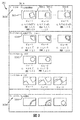
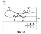
図4Aは、カテーテル405の端に位置するFORS TEEなどの超音波プローブ404のスクリーンショット400Aの一部分を示す。このスクリーンショットは、ディスプレイなどによって提供される。超音波プローブ404は、画像ボリューム407などの所望のビューを捕捉するように配置され、本発明のシステムの実施形態に従って第1の選択されたビューに対応する最適な第1の場所まで操縦される。患者(分かりやすくするためこの図には示されていない)は、手術台などの支持構造体410上に置かれている。システムは、FORS追跡法を使用してFORS SSDを追跡するなど適当な方法を使用して、本明細書に記載されたとおりに超音波プローブ404の位置を決定する。要素402は、ビュー内に存在するカテーテル、アブレーション器具などの外科用器具を表す。超音波プローブ404の場所及び/又は向きを所望のビュー場所及び/又は向きに制御するようにユーザを誘導するため、矢印480などの誘導メッセージが表現される。所望の運動を示すために、矢印480は黒べたで強調表示されている。さらに、例えば超音波プローブ404が所望の場所に到達したと判定されたときに、緑色を使用して矢印480を強調表示してもよい。さらに、2つ以上の超音波プローブが使用される場合には、1つの超音波プローブ又は複数の(例えばそれぞれの)超音波プローブに対する誘導情報が、対応する超音波プローブに関連づけて決定及び表現される。図4Bは、本発明のシステムの実施形態に基づく、第2の選択されたビューに対応する最適な第2の場所まで操縦された図4Aの超音波プローブ404のスクリーンショット400Bの一部分を示す。超音波プローブ404の場所を決定するため、本明細書に記載されたSSDへの問合せがなされる。
FIG. 4A shows a portion of
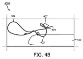
図5は、本発明のシステムの実施形態に基づく、第2の選択されたビューに対応する最適な第2の場所まで操縦された図4Aの超音波プローブ404のスクリーンショット500であり、円590などの任意選択の場所指示子を含むスクリーンショット500の一部分を示す。超音波プローブ404が、対応するビュー(例えばこの実施形態では第2のビュー)にある、又は実質的にあると判定されたとき、システムは、超音波プローブ404が対応する場所にあることを示す指示子590などの指示子を表現する。しかしながら、他の実施形態では、指示子590が強調表示(例えば超音波プローブ404が適切な場所にあることを示す緑色、選択されたエリアに対応する適切な場所にないことを示す赤色など)を含む。さらに、それらの色は、深度、焦点などの超音波パラメータ設定も示す。他の実施形態では、システムが、画像ボリューム407を捕捉するために対応するビューの所望のエリア(場所)に到達するように超音波プローブを移動させる方向及び/又は向きを示す矢印を生成することが想定される。超音波プローブ404の場所を決定するため、本明細書に記載されたSSDへの問合せがなされる。
FIG. 5 is a
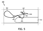
図6は、本発明のシステムの実施形態に基づく、選択されたビューに対応する最適な場所まで操縦された超音波プローブ404のスクリーンショット600であり、円690などの任意選択の場所指示子を含むスクリーンショット600の一部分を示す。円690は、異なるビューに対する最適な場所を示し、これらの異なるビューのそれぞれに対する超音波パラメータ設定を示すために円690は着色され、又は他の方法で強調表示される。例えば、円の色は深度、焦点などの超音波パラメータ設定を示す。異なるビューは、以前に操縦された位置からのものか、又はモデル若しくはデータベースから構築されたものである。超音波プローブ404が対応するビューを捕捉することができるよう超音波プローブ404の場所を決定するため、SSDへの問合せがなされる。
FIG. 6 is a
これに応じて、本発明のシステムの実施形態は、1つのビューに対する超音波プローブの場所及び場所に対する対応する超音波パラメータ情報(例えば超音波プローブの位置及び/又は向き)を記録し、且つ/又は呼び出すためにFORS法が超音波画像診断と組み合わされた方法を提供する。例えば、心エコー技師(echocardiographer)などの臨床医が所望の場所まで操縦し、焦点、深度、走査角などの超音波パラメータを調整する。システムはこれらの設定を、後の使用のために所望の場所(例えばビュー)に関連づけて記憶する。さらに、本発明のシステムの実施形態が、後の使用のために選択されたビューに関連づけて記憶したい設定を選択するオプションをユーザに提供することが想定される。 Accordingly, embodiments of the system of the invention record and / or record the location and corresponding ultrasonic parameter information (eg, position and / or orientation of the ultrasonic probe) of the ultrasonic probe with respect to one view. Or provide a method in which the FORS method is combined with ultrasound imaging to call. For example, a clinician, such as an echocardiogram, steers to the desired location and adjusts ultrasonic parameters such as focus, depth, and scanning angle. The system stores these settings in association with the desired location (eg, view) for later use. Further, it is envisioned that embodiments of the system of the present invention provide the user with an option to select the settings they want to remember in association with the selected view for later use.
さらに、本発明のシステムの実施形態が、最適な位置及び/又はビューがいつ取得されたのかを、システムのメモリに記憶された任意選択の位置及び/又はビューの比較に基づいて自動的に検出することが想定される。最適な位置が取得されたと判定されたとき、システムは、そのことをユーザに知らせ、対応するビューの超音波情報を取得するために超音波プローブによって使用された設定及び/又はパラメータを記憶する。さらに、(例えばそれぞれが1つのビューに対応する)いくつの位置及び/又は向きをシステムのメモリに記憶するのかを、ユーザが、患者の解剖学的構造及び/又は実行中の手技に応じて定義することが想定される。 Further, an embodiment of the system of the present invention automatically detects when the optimum position and / or view was acquired based on an arbitrary selection of position and / or view comparison stored in the memory of the system. It is expected to be done. When it is determined that the optimal position has been obtained, the system informs the user and stores the settings and / or parameters used by the ultrasonic probe to obtain the ultrasonic information for the corresponding view. In addition, the user defines how many positions and / or orientations (eg, each corresponding to one view) are stored in the system's memory, depending on the patient's anatomy and / or the procedure being performed. It is expected to be done.
ビュー及び関連情報がシステムのメモリに記憶された後、ユーザ(例えば臨床医、医師など)が、LVOTなどの以前に保存された(例えば位置合せされたビューと考えられる)ビューに戻りたいとき、システムは、ユーザが超音波プローブを以前に保存されたビューまで再び誘導するのに適当な誘導情報(例えば矢印などの図形、音声情報(右へ行ってくださいなど)、触覚フィードバックなど)を表現する誘導機能を提供する。次いで、視診のため、超音波情報(例えば画像)が、保存された対応するビューに関連づけて以前に記憶された関連パラメータを使用して捕捉され、且つ/又はメモリから呼び出される。さらに、ユーザが、以前に保存されたビューを選択し、システムが、最適な画像を生成する対応するパラメータに従って、自動的に超音波プローブを所望の位置まで移動させ、超音波パラメータなどのパラメータを設定するように、閉ループ・ロボット・コントローラを制御することが想定される。 When a user (eg, clinician, doctor, etc.) wants to return to a previously saved (eg, considered aligned view) view, such as LVOT, after the view and related information have been stored in the system's memory. The system represents guidance information appropriate for the user to reguide the ultrasound probe to a previously saved view (eg, figures such as arrows, audio information (go to the right, etc.), tactile feedback, etc.). Provides guidance function. For inspection, ultrasound information (eg, an image) is then captured using previously stored relevant parameters associated with the saved corresponding view and / or recalled from memory. In addition, the user selects a previously saved view and the system automatically moves the ultrasound probe to the desired position according to the corresponding parameters that produce the best image, setting parameters such as ultrasound parameters. It is envisioned to control a closed-loop robot controller to set.
本発明のシステムの実施形態が、経中隔穿刺の実行、僧帽弁までの操縦、左心耳(LAA)閉鎖装置の展開、僧帽弁クリップなどの異なる手技及びこれらの異なる手技の異なる部分に対して最適なビューを生成するために使用することができる最適な位置及び対応する超音波設定を記憶することも想定される。これらの手技中に、システムは、対応する手技のワークフローが単純化及び短縮されるような誘導を提供する。このことは特に、難しい解剖学的構造内で手技を実行するとき、及び/又は良好な画像を取得することが難しいときに言える。 Embodiments of the system of the present invention cover different procedures such as performing transseptal puncture, maneuvering to the mitral valve, deploying the left atrial appendage (LAA) closure device, mitral valve clip, and different parts of these different procedures. On the other hand, it is also envisioned to store the optimum position and corresponding ultrasound settings that can be used to generate the optimum view. During these procedures, the system provides guidance that simplifies and shortens the workflow of the corresponding procedure. This is especially true when performing procedures within difficult anatomical structures and / or when it is difficult to obtain good images.
さらに、本発明のシステムの実施形態が、手技の1つのワークフローにおいて、異なるそれぞれの超音波プローブに対する動作パラメータ、場所及び/又は向きを含む超音波プローブの組合せ(例えば2つ以上の超音波プローブ)を支援し、そのワークフローの異なる段階中にそれらの異なるパラメータ、場所及び/又は向きに自動的に戻ることが想定される。さらに、本発明のシステムの実施形態が、手技のそのワークフローにおいて、これらの異なるそれぞれの超音波プローブの場所及び/若しくは向きまでの誘導を支援し、且つ/又は、異なる超音波プローブを対応する場所及び/若しくは向きに自動的に戻すための誘導をロボット誘導システムに提供することが想定される。これらのプローブのうちの1つ又は複数のプローブは、1つ又は複数のビューに対する異なる場所及び/又は向きを有する。さらに、誘導システム(例えばGPS)の働きをし、手技のワークフロー中の1つ又は複数の超音波プローブの操縦及び再操縦を単純にするために、FORSに加えて又はFORSとともに、電磁的追跡(EM)、InSitu、光学的追跡などの代替追跡様式が使用されることが想定される。 Further, an embodiment of the system of the present invention is a combination of ultrasonic probes (eg, two or more ultrasonic probes) that includes operating parameters, locations and / or orientations for each different ultrasonic probe in one workflow of the procedure. It is envisioned that they will automatically return to their different parameters, locations and / or orientations during different stages of their workflow. Further, embodiments of the system of the present invention assist in guiding to the location and / or orientation of each of these different ultrasonic probes and / or corresponding locations of different ultrasonic probes in the workflow of the procedure. It is envisioned that the robot guidance system will be provided with guidance for automatically returning to and / or orientation. One or more of these probes have different locations and / or orientations for one or more views. In addition, electromagnetic tracking (in addition to or with FORS) to act as a guidance system (eg GPS) and to simplify the maneuvering and re-maneuvering of one or more ultrasonic probes in the workflow of the procedure. It is envisioned that alternative tracking modalities such as EM), InSitu, and optical tracking will be used.
これに応じて、本発明のシステムの実施形態は、手術シーン(surgical scene)の(例えば標準化された及び/又は患者に合わせて個人化された)突出したビューを見つけ、再生することが実行されるシステム及び方法を提供する。ユーザが、所望の位置及び/又は向きにおいて超音波情報を取得するために超音波プローブをその所望の位置及び/又は向きに直ちに且つ容易に配置することができるように、システムは、直観的な命令をユーザに提供する。システムは、視覚化パラメータを単純にし、超音波プローブの位置、向き、超音波画像利得、深度などのこれらのパラメータを呼び出し、ディスジョイントなサブシステム及び/又はプローブ間であってもこれらのパラメータを設定する。これに応じて、本発明のシステムの実施形態はOSS法などを使用して、超音波誘導手技において所望のビューを記録し、且つ/又は呼び出す。 Correspondingly, embodiments of the system of the invention are performed to find and regenerate prominent views (eg, standardized and / or personalized to the patient) of the surgical scene. System and method. The system is intuitive so that the user can immediately and easily place the ultrasonic probe in the desired position and / or orientation in order to obtain the ultrasonic information in the desired position and / or orientation. Provide instructions to the user. The system simplifies the visualization parameters and calls these parameters such as ultrasound probe position, orientation, ultrasound image gain, depth, and even between disjoint subsystems and / or probes. Set. Correspondingly, embodiments of the system of the present invention record and / or recall the desired view in an ultrasonic guided procedure using the OSS method or the like.
1つ又は複数の実施形態の超音波関連部分の例
臨床医が装置を操縦し手術部位において治療を実施しようとするときには、適切な治療を保証するために、多数のビューポイントから周囲の手術部位を見る必要がある。例えば、最適な画像品質を得るために、利得、圧縮、コントラスト、深度などの超音波設定及び/又はパラメータをビューごとに調整する必要がある。本発明のシステムの実施形態は、超音波法とOSS法の組合せを組み込んで、超音波設定の記録及び呼び出しの際に、以下の変形実施形態を用いて臨床医を支援することができる。ユーザがコマンドを開始する(例えばボタンをクリックする)と、システムは、関連する全ての超音波設定(例えばパラメータ)を、例えばOSSによる関連プローブ位置及び/又は向きとともに読み取り、記憶する。本発明のシステムの実施形態によれば、これらの設定は次いで、保存されたビューを臨床医が後に復元することができるように呼び出される。システムはさらに、1つ又は複数のビューに対する適切な位置及び/又は向きを示す仮想の超音波プローブのオーバレイを、例えば関心のエリアの記憶された画像の上に生成する。
Examples of ultrasound-related parts of one or more embodiments When a clinician steers the device to perform treatment at the surgical site, from multiple viewpoints to the surrounding surgical site to ensure proper treatment. Need to see. For example, ultrasound settings and / or parameters such as gain, compression, contrast, and depth may need to be adjusted from view to view for optimal image quality. Embodiments of the system of the present invention can incorporate a combination of ultrasonic and OSS methods to assist the clinician with the following modified embodiments when recording and recalling ultrasonic settings. When the user initiates a command (eg, clicks a button), the system reads and stores all relevant ultrasound settings (eg, parameters), eg, along with the relevant probe position and / or orientation by OSS. According to embodiments of the system of the invention, these settings are then recalled so that the clinician can later restore the saved view. The system also generates an overlay of virtual ultrasound probes showing the appropriate position and / or orientation for one or more views, eg, on a stored image of the area of interest.
さらに、超音波画像中の突出したビューの自動検出の後、本発明のシステムの実施形態は、このことを臨床医に通知し、例えば、必要に応じて臨床医がプローブ位置及び/又は向き並びに超音波設定及び/又はパラメータを微調整するためのユーザ・インタフェースを提供する。このような通知は、超音波画像が患者解剖学的構造に位置合せされており、そのため、超音波のビューの中にある解剖学的構造の部分が概ね分かっているためである。この知識は、画像セグメント化技法と組み合わせて使用される。画像セグメント化技法は当技術分野で知られており、分かりやすくするため、この技法についてここでさらに論じることはしない。次いで、本明細書で論じたとおりに、動作パラメータ、場所などの1つ又は複数の部分が保存され、続いて呼び出される。 Further, after automatic detection of a protruding view in the ultrasound image, embodiments of the system of the invention notify the clinician of this, eg, the clinician as needed for probe position and / or orientation and as well. Provides a user interface for fine-tuning ultrasound settings and / or parameters. Such notification is because the ultrasound image is aligned with the patient's anatomy, so that the portion of the anatomy within the ultrasound view is largely known. This knowledge is used in combination with image segmentation techniques. Image segmentation techniques are known in the art and are not discussed further here for clarity. Then, as discussed herein, one or more parts such as operating parameters, locations, etc. are stored and subsequently recalled.
手術シーンを評価する際に臨床医を支援するため、超音波プローブの位置を変更したり、又は超音波設定及び/若しくはパラメータをさらに調整したりする必要なしに、記録された2つ以上のビュー(例えば所与の手技に対する多数のビュー、例えば2つ、3つ、4つ、5つ、...、全てのビューの記憶された超音波画像)を同時に提示することも想定される。画像及び超音波プローブはともに患者の解剖学的構造に対して(例えば患者ワークスペースに対して)位置合せされているため、画像は、別個のビューとして示され、且つ/又は適切な解剖学的関係で単一の画像中に(例えばそれぞれのビューによって提供された解剖学的配置に基づく配置で単一の画像内に)一緒に提供される。さらに、手技に対してビューの配列が十分に確立されている場合、システムは、全ての所望のビューを獲得するまでの段階で臨床医を支援し、臨床医に指示を出す。これらのビューは、ビューのライブラリとして記憶されており、又は臨床医によって術前に生成される。これらのビューは次いで記憶され、手技のためのワークフローの部分を形成し、要望があったときにシステム及び/又はユーザによって呼び出される。 Two or more recorded views without the need to reposition the ultrasound probe or further adjust the ultrasound settings and / or parameters to assist the clinician in assessing the surgical scene. It is also envisioned to present (eg, a large number of views for a given procedure, eg, two, three, four, five, ..., stored ultrasound images of all views) at the same time. Since both the image and the ultrasound probe are aligned to the patient's anatomy (eg, to the patient's workspace), the image is shown as a separate view and / or the appropriate anatomy. Relationships are provided together in a single image (eg, in a single image with an arrangement based on the anatomical arrangement provided by each view). In addition, if the sequence of views is well established for the procedure, the system assists and directs the clinician in the process of obtaining all the desired views. These views are stored as a library of views or are generated preoperatively by the clinician. These views are then stored, form part of the workflow for the procedure, and are called by the system and / or the user when requested.
1つ又は複数の実施形態の手技関連部分の例
外科的手技は、共通の解剖学的ビューポイントの獲得を必然的に伴う。特定の外科的手技中に超音波プローブを追跡するOSS法の組合せは以下のように利用される。システムは、超音波プローブが所望のビューに(例えば適切な位置及び/又は向きに)あるかどうかを、OSS法を使用して超音波プローブを追跡することによって判定する。(例えば所望のビューにおいて)所望の超音波プローブ位置及び/又は向きが自動検出されると、システムは、(臨床医などの)ユーザにそのことを通知し、ユーザが超音波設定及び/又はパラメータを手動で調整することを提供する。このような通知が可能なのは、OSS法が患者の解剖学的構造に対して位置合せされており、多くの場合に、所望のビューが演繹的に分かっているためである。次いで、本明細書で論じたとおり、それぞれのビューに対するパラメータ及び/又は設定の完全セットと対応する超音波情報とが、プロセス・ワークフローのビュー・ライブラリとしてシステムのメモリに記憶され、続いてプロセス・ワークフロー中に呼び出される。さらに、本発明のシステムの実施形態では、プロセス・ワークフローに対する記憶された所望の標準的なビューが、拡張現実視覚的表現として表示され、将来のプロセス・ワークフロー中に手術シーンの適切な評価のために集められる全てのビュー(例えば単一の画像にまとめられた複数のビュー又は他のやり方で適切な解剖学的位置に配置された複数のビュー)をユーザに示すことが想定される。実施形態によれば、それらのビューは、手技ワークフローに従った順序で提示され、且つ/又は要望に応じて順序づけ/再順序づけされる。
Examples of procedure-related parts of one or more embodiments Surgical procedures necessarily involve the acquisition of a common anatomical viewpoint. A combination of OSS methods that track an ultrasonic probe during a particular surgical procedure is utilized as follows. The system determines if the ultrasonic probe is in the desired view (eg, in the proper position and / or orientation) by tracking the ultrasonic probe using the OSS method. When the desired ultrasound probe position and / or orientation is auto-detected (eg in the desired view), the system notifies the user (such as a clinician) of this and the user sets and / or parameters the ultrasound. Provides manual adjustment. Such notification is possible because the OSS method is aligned with the patient's anatomy and, in many cases, the desired view is deductively known. Then, as discussed herein, the complete set of parameters and / or settings for each view and the corresponding ultrasound information are stored in the system's memory as a process workflow view library, followed by the process process. Called during workflow. Further, in embodiments of the system of the present invention, a desired standard view stored for the process workflow is displayed as an augmented reality visual representation for proper evaluation of the surgical scene during future process workflows. It is envisaged to show the user all the views that are collected in (eg, multiple views combined into a single image or otherwise placed in appropriate anatomical positions). According to embodiments, the views are presented in order according to the procedure workflow and / or ordered / reordered as desired.
1つ又は複数の実施形態の形状感知関連部分の例
1つ又は複数の実施形態によれば、外科的手技を実行するために望まれる/必要なビューを獲得するために超音波プローブをどこにおくべきかをユーザ(例えば臨床医など)に示すため、プローブの仮想オーバレイが表現される。例えば、超音波プローブの連続した1つ又は複数の部分(例えばプローブの全体までの部分又は挿入された部分)の形状を表現し、それによって、所望の1つ又は複数のビューを獲得するために超音波プローブの位置及び/又は向きをどのようにすべきかに関してより有益な情報をユーザに提供する。
Examples of Shape Sensing Related Parts in One or More Embodiments According to one or more embodiments, where to place the ultrasound probe to obtain the desired / required view to perform the surgical procedure. A virtual overlay of the probe is represented to indicate to the user (eg, a clinician) what should be done. For example, to represent the shape of one or more contiguous parts of an ultrasonic probe (eg, the entire or inserted part of the probe), thereby obtaining the desired one or more views. It provides the user with more useful information about what the position and / or orientation of the ultrasonic probe should be.
(例えば挿入された部分の)完全な形状情報が表現され、このような情報は、超音波プローブの手動誘導が使用されるときに特に有用である。所望の位置及び/又は向きまで超音波プローブを直ちに操作するロボット・マニピュレータとは違い、人間オペレータ(例えば臨床医など)は、ディスジョイントな座標系を認知的にマップしなければならないことによって生じる手及び眼の非直観的な協調のため、同じ作業を難しいと感じる。これに応じて、超音波プローブの完全な形状情報の表現は、場合によっては冗長であることもあるが、プローブ位置及び/又は向きの関係に関する情報を(例えば図形表示などを使用して)人間オペレータに提供する。さらに、プローブはOSS法を使用して追跡されるため、画像又はプローブ座標系は、ユーザの視点に対して位置合せされ、したがって、ディスジョイントな座標系を統一し、プロセス・ワークフロー中の超音波プローブの手動誘導を単純にする。ロボット手技では、最終的にユーザが、ロボット手技によって取得された位置及び/又は向きを必要に応じて最終的な位置及び/又は向きに調整する。 Complete shape information (eg, of the inserted part) is represented, which is especially useful when manual induction of the ultrasonic probe is used. Unlike robotic manipulators, which immediately operate an ultrasonic probe to the desired position and / or orientation, human operators (such as clinicians) have to cognitively map disjointed coordinate systems. And because of the non-intuitive coordination of the eyes, I find the same task difficult. Correspondingly, the representation of the complete shape information of the ultrasonic probe may be redundant in some cases, but humans (eg, using graphic representations, etc.) provide information about the relationship between probe position and / or orientation. Provide to the operator. In addition, because the probe is tracked using the OSS method, the image or probe coordinate system is aligned with the user's point of view, thus unifying the disjoint coordinate system and ultrasound during the process workflow. Simplify manual induction of the probe. In the robot procedure, the user finally adjusts the position and / or orientation acquired by the robot procedure to the final position and / or orientation as needed.
図7は、本発明のシステムの実施形態に基づくシステム700の一部分を示す。例えば、本発明のシステムの一部分は、プロセッサ710(例えばコントローラ)を含み、プロセッサ710は、メモリ720、ディスプレイ730などの表現装置を含むユーザ・インタフェース(UI)、形状感知装置(SSD)などのセンサ740、1つ又は複数の超音波プローブ750、及びユーザ入力装置770に動作可能に結合されている。メモリ720は、アプリケーション・データ及び説明した動作に関する他のデータを記憶する任意のタイプの装置である。このアプリケーション・データ及び他のデータは、本発明のシステムに基づく動作ステップを実行するようにプロセッサ710を構成する(例えばプログラムする)ためにプロセッサ710によって受信される。このように構成されたプロセッサ710は、本発明のシステムの実施形態に従って実行するのに特に適した特殊目的機械になる。動作ステップは、例えばシステム設定に基づく位置合せシステムによってシステムを構成することを含む。動作ステップはさらに、所望のビュー及び関連パラメータを含むメモリ720からワークフローを取得するプロセッサ710を含み、この関連パラメータは、SSD740の位置を超音波プローブ750に関して相関させる(例えばSSD740の位置を超音波プローブ(750)の位置に関係づけるオフセット情報を提供する)相関情報を含む、例えば1つ又は複数の超音波プローブ750及びSSD740に対する設定に関するパラメータなどである。
FIG. 7 shows a portion of a
FORS追跡法を利用して、SSD740の場所を示すセンサ情報信号が生成されるようにするなど、プロセッサ710は、1つ又は複数の追跡システム(例えばSSD740)を制御する。プロセッサ710は、センサ情報などの受信信号を処理し、これらの信号を場所信号に変換し、内容を生成する。この内容は、画像情報(例えば超音波画像情報を含む静止及び/又はビデオ画像)、データ、パラメータ、位置、向き、誘導情報及び/又はグラフを含み、例えばディスプレイ730、スピーカなどのシステムのUI上に表現される。この内容は、本発明のシステムの医療用画像化システムによって生成された画像情報、誘導情報などを含む。さらに、この内容は次いで、後の使用のためにメモリ720などのシステムのメモリに記憶される。したがって、動作ステップは、内容を要求すること、提供すること、及び/又は表現することを含む。プロセッサ710は、ビデオ情報などの内容を、システムのディスプレイなどシステムのUI上に表現する。プロセッサ710は、システムのUIを決定し、例えばシステムのディスプレイ上に表現する。
The
ユーザ入力770は、キーボード、マウス、トラックボール又は他の装置、例えばタッチセンシティブ・ディスプレイを含み、これらは、独立型の装置であり、或いはパーソナル・コンピュータ、パーソナル・ディジタル・アシスタント(PDA)、移動電話(例えばスマートホン)、モニタ、スマート若しくはダム端末、又は有線及び/若しくは無線通信リンクなどの動作可能なリンクを介してプロセッサ710と通信する他の装置の部分など、1つのシステムの部分である。ユーザ入力装置770は、本明細書に記載されたUI内での対話を可能にすることを含め、プロセッサ710と対話するように動作可能である。明らかに、プロセッサ710、メモリ720、ディスプレイ730及び/又はユーザ入力装置770は、全体として又は部分的に、クライアント及び/又はサーバなどのコンピュータ・システム又は他の装置の一部分である。
本発明のシステムの方法は、コンピュータ・ソフトウェア・プログラムによって実行されるのに特に適しており、このようなプログラムは、本発明のシステムによって記述及び/又は想定される個々のステップ、ステップ、モジュールなどのうちの1つ又は複数に対応するモジュールを含む。言うまでもなく、このようなプログラムは、集積チップ、周辺装置又はメモリ、例えばメモリ720又はプロセッサ710に結合された他のメモリなどのコンピュータ可読媒体の中に実施される。
The methods of the system of the present invention are particularly suitable for being executed by computer software programs, such programs as individual steps, steps, modules, etc. described and / or envisioned by the system of the present invention. Includes modules corresponding to one or more of them. Needless to say, such a program is implemented in a computer-readable medium such as an integrated chip, peripheral or memory, such as
メモリ720に含まれるプログラム及び/又はプログラム部分は、プロセッサ710を、本明細書に開示された方法、動作ステップ及び機能を実施するように構成する。メモリは、例えばクライアント及び/若しくはサーバ間に分散していても、又は局所メモリであってもよく、追加のプロセッサが提供されてもよいプロセッサ710も、分散していても、又は単独であってもよい。メモリは、電気、磁気若しくは光学メモリとして、又はこれらのタイプの記憶装置若しくは他のタイプの記憶装置の組合せとして実施される。さらに、用語「メモリ」は、プロセッサ710がアクセスできるアドレス指定可能空間内のアドレスから読み取り、又はそのようなアドレスに書き込むことができる任意の情報を包含するように十分に広く解釈されるべきである。この定義によれば、ネットワークを介してアクセス可能な情報もメモリ内にあることになる。これは例えば、プロセッサ710は、本発明のシステムに従って動作するためにネットワークから情報を取り出すことができるためである。
The program and / or program portion contained in the
プロセッサ710は、ユーザ入力装置770からの入力信号に応答して、及びネットワークの他の装置に応答して、制御信号を提供し、且つ/又は動作を実行するように、並びにメモリ720に記憶された命令を実行するように動作可能である。プロセッサ710は、マイクロプロセッサ、特定用途向け集積回路、汎用集積回路、論理装置などのうちの1つ又は複数を含む。さらに、プロセッサ710は、本発明のシステムに従って実行する専用プロセッサであり、又は、本発明のシステムに従って実行するために多くの機能のうちの1つの機能だけが機能する、特にプログラムされた汎用プロセッサである。プロセッサ710は、プログラム部分、多数のプログラム・セグメントを利用して動作し、且つ/又は、プロセッサ710は、専用若しくは多目的集積回路を利用するハードウェア装置である。本発明のシステムの実施形態は、画像を獲得及び/又は再構成する画像化法を提供する。適当なアプリケーションは、超音波画像などの画像化システムを含む。しかしながら、限定はされないが、本発明のシステムの実施形態はさらに、MRI、コンピュータ支援断層撮影(CAT)、光学、X線画像化システム、及び/又はこれらの組合せなどの画像化システムを含んでもよいことを理解すべきである。さらに、本発明のシステムの実施形態は、異なる座標系を有する1つ又は複数の画像化システム(例えば超音波、CTスキャン、MRIなど)から画像及び/又はセンサ情報を生成及び表現する外科的介入術式に理想的に適しており、結果(例えば画像、位置及び/又は向き情報)は、統一された座標系を用いてリアルタイムで提供される。
当業者には、本発明のシステムのさらなる変更がすぐに思い浮かぶであろう。このような本発明のシステムのさらなる変更は以下の特許請求の範囲によって包含される。最後に、以上の議論の目的は単に、本発明のシステムを例示することであり、以上の議論が、添付の特許請求の範囲を、特定の実施形態又は一群の実施形態に限定すると解釈すべきではない。したがって、例示的な実施形態に関して本発明のシステムを説明したが、以下の特許請求の範囲に記載された本発明のシステムのより幅広い意図された趣旨及び範囲を逸脱しない多数の変更及び代替実施形態が当業者によって考案される可能性があることも理解すべきである。加えて、本明細書に含まれる項見出しは、再検討を容易にすることを意図したものであり、本発明のシステムの範囲を限定することを意図したものではない。したがって、本明細書及び図面は、例示のためのものであるとみなすべきであり、本明細書及び図面が、添付の特許請求の範囲を限定することは意図されていない。 Further modifications of the system of the present invention will be immediately apparent to those skilled in the art. Such further modifications of the system of the present invention are covered by the following claims. Finally, the purpose of the above discussion is merely to illustrate the system of the present invention, which should be construed as limiting the scope of the appended claims to a particular embodiment or group of embodiments. is not it. Therefore, although the system of the present invention has been described with respect to exemplary embodiments, a number of modifications and alternative embodiments that do not deviate from the broader intended purpose and scope of the system of the invention described in the claims below. It should also be understood that may be devised by one of ordinary skill in the art. In addition, the term headings contained herein are intended to facilitate reexamination and are not intended to limit the scope of the system of the invention. Therefore, the specification and drawings should be considered as exemplary only, and the specification and drawings are not intended to limit the scope of the appended claims.
添付の特許請求の範囲を解釈する際には、以下のことを理解しておくべきである。
a)語「備える(comprising)」は、所与の請求項に記載された要素又はステップ以外の要素又はステップの存在を排除しない。
b)要素の前の語「a」又は「an」は、そのような要素が複数存在することを排除しない。
c)請求項中の参照符号は、その請求項の範囲を限定しない。
d)同じアイテムによって、又はハードウェア若しくはソフトウェアで実施された同じ構造若しくは機能によって、いくつかの「手段」が表現されることがある。
e)開示された要素は、ハードウェア部分(例えば別々の電子回路及び集積電子回路を含む)、ソフトウェア部分(例えばコンピュータ・プログラミング)、及びこれらの任意の組合せからなることがある。
f)ハードウェア部分は、アナログ部分とディジタル部分のうちの一方又は両方からなることがある。
g)特段の記載なしに、開示された装置又は開示された装置の部分が、一体に結合されたり、又はさらなる部分に分割されたりすることがある。
h)特段の言及がない限り、ステップ又はステップの特定の順序が必須となることは意図されていない。
i)用語「複数の」要素は、記載された2つ以上の要素を含み、特定の要素数範囲を暗示しない。すなわち、複数の要素は、2つの要素でしかなくてもよく、計り知れない数の要素を含んでもよい。
j)用語「及び/又は」並びにその形式素は、特許請求の範囲及び本発明のシステムの1つ又は複数の実施形態に従って、列挙された要素のうちの1つ又は複数の要素だけがシステム内に適切に存在すればよいことを意味すると理解すべきである。
When interpreting the appended claims, the following should be understood.
a) The term "comprising" does not preclude the existence of an element or step other than the element or step described in a given claim.
b) The word "a" or "an" before an element does not preclude the existence of more than one such element.
c) The reference code in the claim does not limit the scope of the claim.
d) Several "means" may be represented by the same item or by the same structure or function implemented in hardware or software.
e) The disclosed elements may consist of hardware parts (including, for example, separate and integrated electronic circuits), software parts (eg, computer programming), and any combination thereof.
f) The hardware portion may consist of one or both of an analog portion and a digital portion.
g) Unless otherwise stated, the disclosed device or parts of the disclosed device may be integrally combined or subdivided into additional parts.
h) Unless otherwise stated, it is not intended that a step or a specific sequence of steps is required.
i) The term "plurality" of elements includes the two or more elements described and does not imply a particular element number range. That is, the plurality of elements may be only two elements and may include an immeasurable number of elements.
j) The term "and / or" and its formal elements are such that only one or more of the listed elements are in the system according to the claims and one or more embodiments of the system of the invention. It should be understood that it means that it should exist properly.
Claims (15)
前記超音波プローブの場所及び向きのうちの少なくとも一方を、前記形状感知装置から受信した位置センサ情報に基づいて決定し、
前記メモリに記憶されたワークフローの複数のビューの中から1つのビューを選択し、
選択されたビューに対するビュー設定情報であって、それぞれのビューに対する前記超音波プローブの位置及び向きのうちの少なくとも一方とパラメータとを含む前記ビュー設定情報を前記メモリから取得し、
前記超音波プローブの決定された場所及び向きと前記選択されたビューに対する前記超音波プローブの位置及び向きのうちの前記少なくとも一方との比較に基づいて、誘導情報を決定し、
決定された前記誘導情報を前記表現装置上に表現し、前記選択されたビューに対する前記ビュー設定情報の前記パラメータに基づいて超音波プローブ・パラメータを設定する、
外科用誘導システム。 A memory, a representation device, an ultrasonic probe, a shape sensing device associated with the ultrasonic probe and having a predetermined position and orientation with respect to the ultrasonic probe, the memory, and the representation. A surgical guidance system that includes a device and a controller coupled to the shape sensing device.
At least one of the location and orientation of the ultrasonic probe is determined based on the position sensor information received from the shape sensing device.
Select one view from the plurality of views of the workflow stored in the memory.
The view setting information for the selected view, including at least one of the position and orientation of the ultrasonic probe for each view and a parameter, is acquired from the memory.
Guidance information is determined based on a comparison of the determined location and orientation of the ultrasonic probe with at least one of the positions and orientations of the ultrasonic probe with respect to the selected view.
The determined guidance information is represented on the representation device and the ultrasonic probe parameters are set based on the parameters of the view setting information for the selected view.
Surgical guidance system.
前記超音波プローブの場所及び向きのうちの少なくとも一方を位置センサ情報に基づいて決定するステップと、
メモリに記憶されたワークフローの複数のビューの中から1つのビューを選択するステップと、
選択されたビューに対するビュー設定情報であって、それぞれのビューに対する前記超音波プローブの位置及び向きのうちの前記少なくとも一方とパラメータとに関する情報を含むビュー設定情報を取得するステップと、
前記超音波プローブの場所及び向きと前記選択されたビューに対する前記超音波プローブの位置及び向きのうちの前記少なくとも一方との比較に基づいて、誘導情報を決定するステップと、
決定された前記誘導情報を出力し、前記選択されたビューに対する前記ビュー設定情報の前記パラメータに基づいて超音波プローブ・パラメータを設定するステップとを有する、
方法。 A method of inducing an ultrasonic probe to obtain ultrasonic information, said method performed by at least one controller.
The step of determining at least one of the location and orientation of the ultrasonic probe based on the position sensor information, and
A step to select one view from multiple views of the workflow stored in memory,
A step of acquiring view setting information for the selected view, including information about at least one of the positions and orientations of the ultrasonic probe with respect to each view and parameters.
A step of determining guidance information based on a comparison of the location and orientation of the ultrasonic probe with at least one of the positions and orientations of the ultrasonic probe with respect to the selected view.
It has a step of outputting the determined guidance information and setting ultrasonic probe parameters based on the parameters of the view setting information for the selected view.
Method.
超音波プローブの場所及び向きのうちの少なくとも一方を位置センサ情報に基づいて決定するステップと、
ワークフローの位置合せされた少なくとも1つのビューの中から1つのビューを選択するステップと、
選択されたビューに対するビュー設定情報であって、位置合せされたそれぞれのビューに対するパラメータ及びそれぞれのビューに対する前記超音波プローブの位置及び向きのうちの少なくとも一方に関する情報を含むビュー設定情報を取得するステップと、
前記超音波プローブの場所及び向きと前記選択されたビューに対する前記超音波プローブの位置及び向きのうちの前記少なくとも一方との比較に基づいて、誘導情報を決定するステップと、
決定された前記誘導情報を出力し、前記選択されたビューに対する前記ビュー設定情報の前記パラメータに基づいて超音波プローブ・パラメータを設定するステップとを
実施するためのコンピュータ命令を含む、非一時的コンピュータ可読媒体。 When run by the processor
The step of determining at least one of the location and orientation of the ultrasonic probe based on the position sensor information,
The step of selecting one view from at least one aligned view of the workflow,
A step of acquiring view setting information for the selected view, including information about parameters for each aligned view and at least one of the position and orientation of the ultrasonic probe with respect to each view. When,
A step of determining guidance information based on a comparison of the location and orientation of the ultrasonic probe with at least one of the positions and orientations of the ultrasonic probe with respect to the selected view.
A non-transient computer that includes computer instructions for outputting the determined guidance information and setting ultrasonic probe parameters based on the parameters of the view configuration information for the selected view. Readable medium.
Applications Claiming Priority (3)
| Application Number | Priority Date | Filing Date | Title |
|---|---|---|---|
| US201662356566P | 2016-06-30 | 2016-06-30 | |
| US62/356,566 | 2016-06-30 | ||
| PCT/EP2017/065946 WO2018002109A1 (en) | 2016-06-30 | 2017-06-28 | Medical navigation system employing optical position sensing and method of operation thereof |
Publications (3)
| Publication Number | Publication Date |
|---|---|
| JP2019521768A JP2019521768A (en) | 2019-08-08 |
| JP2019521768A5 JP2019521768A5 (en) | 2020-08-06 |
| JP6907247B2 true JP6907247B2 (en) | 2021-07-21 |
Family
ID=59337632
Family Applications (1)
| Application Number | Title | Priority Date | Filing Date |
|---|---|---|---|
| JP2018568808A Active JP6907247B2 (en) | 2016-06-30 | 2017-06-28 | Medical navigation system using optical position sensing and how to operate it |
Country Status (5)
| Country | Link |
|---|---|
| US (1) | US11224405B2 (en) |
| EP (1) | EP3478207B1 (en) |
| JP (1) | JP6907247B2 (en) |
| CN (1) | CN109982656B (en) |
| WO (1) | WO2018002109A1 (en) |
Families Citing this family (9)
| Publication number | Priority date | Publication date | Assignee | Title |
|---|---|---|---|---|
| CA3075334C (en) * | 2017-09-07 | 2021-08-31 | Piur Imaging Gmbh | Apparatus and method for determining motion of an ultrasound probe |
| BR112020015940A2 (en) * | 2018-02-08 | 2020-12-15 | Koninklijke Philips N.V. | TRANSESOPHAGEAL ECHOCARDIOGRAPHY PROBE AND METHOD TO CONTROL A WIRELESS TRANSESOPHAGEAL ECHOCARDIOGRAPH PROBE |
| EP3758641A4 (en) * | 2018-03-01 | 2021-12-15 | Auris Health, Inc. | Methods and systems for mapping and navigation |
| CN112135566A (en) * | 2018-05-18 | 2020-12-25 | 富士胶片株式会社 | Ultrasonic system and control method of ultrasonic system |
| CA3130656A1 (en) * | 2018-12-03 | 2020-06-11 | 3Mensio Medical Imaging B.V. | Method, device and system for intracavity probe procedure planning |
| EP3917405A1 (en) * | 2019-02-04 | 2021-12-08 | Google LLC | Instrumented ultrasound probes for machine-learning generated real-time sonographer feedback |
| CN110313939B (en) * | 2019-08-01 | 2020-12-11 | 无锡海斯凯尔医学技术有限公司 | Tissue region-of-interest positioning method, device, equipment and storage medium |
| US11419585B2 (en) * | 2019-11-18 | 2022-08-23 | GE Precision Healthcare LLC | Methods and systems for turbulence awareness enabled ultrasound scanning |
| EP4278981A1 (en) * | 2022-05-16 | 2023-11-22 | Koninklijke Philips N.V. | User guidance in ultrasound imaging |
Family Cites Families (22)
| Publication number | Priority date | Publication date | Assignee | Title |
|---|---|---|---|---|
| US7597663B2 (en) * | 2000-11-24 | 2009-10-06 | U-Systems, Inc. | Adjunctive ultrasound processing and display for breast cancer screening |
| DE10118570B4 (en) | 2001-01-10 | 2004-06-03 | Aesculap Ag & Co. Kg | Surgical device |
| EP2289453B1 (en) * | 2005-06-06 | 2015-08-05 | Intuitive Surgical Operations, Inc. | Laparoscopic ultrasound robotic surgical system |
| JP5127371B2 (en) * | 2007-08-31 | 2013-01-23 | キヤノン株式会社 | Ultrasound image diagnostic system and control method thereof |
| US8183520B2 (en) | 2009-11-13 | 2012-05-22 | Intuitive Surgical Operations, Inc. | Optical fiber shape sensor calibration |
| RU2556783C2 (en) | 2009-12-09 | 2015-07-20 | Конинклейке Филипс Электроникс Н.В. | Combination of ultrasound and x-ray systems |
| US10194831B2 (en) | 2010-02-09 | 2019-02-05 | Koninklijke Philips N.V. | Apparatus, system and method for imaging and treatment using optical position sensing |
| JP2014517907A (en) | 2011-01-28 | 2014-07-24 | コーニンクレッカ フィリップス エヌ ヴェ | Reference markers for starting point identification in optical shape detection systems |
| CN104470419B (en) * | 2012-07-09 | 2018-08-17 | 皇家飞利浦有限公司 | The method and system of intervention for adapting to image guiding |
| EP3679881A1 (en) * | 2012-08-14 | 2020-07-15 | Intuitive Surgical Operations, Inc. | Systems and methods for registration of multiple vision systems |
| WO2014053934A1 (en) | 2012-10-01 | 2014-04-10 | Koninklijke Philips N.V. | System and method for registering shape sensing with imaging using an optimal plane |
| US20140121489A1 (en) * | 2012-10-31 | 2014-05-01 | General Electric Company | Medical imaging system and a portable medical imaging device for performing imaging |
| US10588597B2 (en) * | 2012-12-31 | 2020-03-17 | Intuitive Surgical Operations, Inc. | Systems and methods for interventional procedure planning |
| CN108784702B (en) * | 2013-03-15 | 2021-11-12 | 直观外科手术操作公司 | Shape sensor system for tracking interventional instruments and method of use |
| US10610196B2 (en) * | 2013-06-28 | 2020-04-07 | Koninklijke Philips N.V. | Shape injection into ultrasound image to calibrate beam patterns in real-time |
| EP3025304B1 (en) | 2013-07-23 | 2021-09-08 | Koninklijke Philips N.V. | Registration system for registering an imaging device with a tracking device |
| CN105517489B (en) | 2013-09-06 | 2020-06-05 | 皇家飞利浦有限公司 | Navigation system |
| EP3082610A1 (en) * | 2013-12-17 | 2016-10-26 | Koninklijke Philips N.V. | Shape sensed robotic ultrasound for minimally invasive interventions |
| CN104739508B (en) * | 2013-12-31 | 2017-04-12 | 上海西门子医疗器械有限公司 | Moving position setting method and system of moving component and medical device |
| JP6568084B2 (en) * | 2014-01-24 | 2019-08-28 | コーニンクレッカ フィリップス エヌ ヴェKoninklijke Philips N.V. | Robot control to image devices using optical shape detection |
| JP6365121B2 (en) * | 2014-08-28 | 2018-08-01 | コニカミノルタ株式会社 | Ultrasonic probe and ultrasonic diagnostic apparatus |
| US10646199B2 (en) * | 2015-10-19 | 2020-05-12 | Clarius Mobile Health Corp. | Systems and methods for remote graphical feedback of ultrasound scanning technique |
-
2017
- 2017-06-28 EP EP17739499.6A patent/EP3478207B1/en active Active
- 2017-06-28 WO PCT/EP2017/065946 patent/WO2018002109A1/en unknown
- 2017-06-28 CN CN201780040597.4A patent/CN109982656B/en active Active
- 2017-06-28 US US16/305,917 patent/US11224405B2/en active Active
- 2017-06-28 JP JP2018568808A patent/JP6907247B2/en active Active
Also Published As
| Publication number | Publication date |
|---|---|
| US20200323514A1 (en) | 2020-10-15 |
| JP2019521768A (en) | 2019-08-08 |
| WO2018002109A1 (en) | 2018-01-04 |
| CN109982656A (en) | 2019-07-05 |
| CN109982656B (en) | 2022-04-08 |
| EP3478207A1 (en) | 2019-05-08 |
| EP3478207B1 (en) | 2023-08-09 |
| US11224405B2 (en) | 2022-01-18 |
Similar Documents
| Publication | Publication Date | Title |
|---|---|---|
| JP6907247B2 (en) | Medical navigation system using optical position sensing and how to operate it | |
| US20220096189A1 (en) | Image guided motion scaling for robot control | |
| JP7167285B2 (en) | Ultrasound system and method for breast tissue imaging | |
| US10646290B2 (en) | System and method for configuring positions in a surgical positioning system | |
| US9131986B2 (en) | Methods, devices, and systems for non-mechanically restricting and/or programming movement of a tool of a manipulator along a single axis | |
| JP6553511B2 (en) | C-arm trajectory planning for optimal image acquisition in endoscopic surgery | |
| EP2514366A1 (en) | Automatic ultrasonic scanning system and scanning method thereof | |
| CA2684459C (en) | Methods, devices, and systems for non-mechanically restricting and/or programming movement of a tool of a manipulator along a single axis | |
| WO2017076886A1 (en) | Determining a configuration of a medical robotic arm | |
| RU2015110976A (en) | ROBOTED DEVICE AND SYSTEM SOFTWARE, HARDWARE AND METHODS OF USE FOR SURGICAL INTERVENTION GUIDED ON THE IMAGE AND USING THE ROBOT | |
| JP2018514352A (en) | System and method for fusion image-based guidance with late marker placement | |
| JP2016522725A (en) | System and method for 3D acquisition of ultrasound images | |
| JP2017532131A (en) | System for real-time organ segmentation and instrument navigation during instrument insertion within interventional therapy and method of operation thereof | |
| US20190374130A1 (en) | Medical navigation system using shape-sensing device and method of operation thereof | |
| JP2004223128A (en) | Medical practice supporting apparatus and method | |
| JP2009207677A (en) | Medical image diagnostic apparatus | |
| JP2017532134A (en) | System for real-time organ segmentation and instrument navigation during instrument insertion within interventional therapy and method of operation thereof | |
| CN113116386B (en) | Ultrasound imaging guidance method, ultrasound apparatus, and storage medium | |
| CA3102807A1 (en) | Orientation detection in fluoroscopic images | |
| CA2917654C (en) | System and method for configuring positions in a surgical positioning system | |
| EP3200719B1 (en) | Determining a configuration of a medical robotic arm | |
| JP2020512126A (en) | Force-sensing surface scanning system, device, controller and method | |
| CN113129342A (en) | Multi-modal fusion imaging method, device and storage medium | |
| CN113116384A (en) | Ultrasonic scanning guidance method, ultrasonic device and storage medium | |
| US20230210627A1 (en) | Three-dimensional instrument pose estimation |
Legal Events
| Date | Code | Title | Description |
|---|---|---|---|
| A521 | Request for written amendment filed |
Free format text: JAPANESE INTERMEDIATE CODE: A523 Effective date: 20200626 |
|
| A621 | Written request for application examination |
Free format text: JAPANESE INTERMEDIATE CODE: A621 Effective date: 20200626 |
|
| TRDD | Decision of grant or rejection written | ||
| A977 | Report on retrieval |
Free format text: JAPANESE INTERMEDIATE CODE: A971007 Effective date: 20210528 |
|
| A01 | Written decision to grant a patent or to grant a registration (utility model) |
Free format text: JAPANESE INTERMEDIATE CODE: A01 Effective date: 20210601 |
|
| A61 | First payment of annual fees (during grant procedure) |
Free format text: JAPANESE INTERMEDIATE CODE: A61 Effective date: 20210630 |
|
| R150 | Certificate of patent or registration of utility model |
Ref document number: 6907247 Country of ref document: JP Free format text: JAPANESE INTERMEDIATE CODE: R150 |