JP6906462B2 - Medical image display devices, methods and programs - Google Patents
Medical image display devices, methods and programs Download PDFInfo
- Publication number
- JP6906462B2 JP6906462B2 JP2018035200A JP2018035200A JP6906462B2 JP 6906462 B2 JP6906462 B2 JP 6906462B2 JP 2018035200 A JP2018035200 A JP 2018035200A JP 2018035200 A JP2018035200 A JP 2018035200A JP 6906462 B2 JP6906462 B2 JP 6906462B2
- Authority
- JP
- Japan
- Prior art keywords
- medical image
- interpretation report
- disease
- image
- medical
- Prior art date
- Legal status (The legal status is an assumption and is not a legal conclusion. Google has not performed a legal analysis and makes no representation as to the accuracy of the status listed.)
- Active
Links
- 238000000034 method Methods 0.000 title claims description 43
- 201000010099 disease Diseases 0.000 claims description 85
- 208000037265 diseases, disorders, signs and symptoms Diseases 0.000 claims description 85
- 210000004556 brain Anatomy 0.000 claims description 52
- 238000004458 analytical method Methods 0.000 claims description 48
- 238000012937 correction Methods 0.000 claims description 41
- 230000004044 response Effects 0.000 claims description 9
- 206010008118 cerebral infarction Diseases 0.000 claims description 7
- 208000026106 cerebrovascular disease Diseases 0.000 claims description 7
- 238000012986 modification Methods 0.000 claims description 2
- 230000004048 modification Effects 0.000 claims description 2
- 206010061216 Infarction Diseases 0.000 description 45
- 230000007574 infarction Effects 0.000 description 45
- 230000008569 process Effects 0.000 description 26
- 238000012545 processing Methods 0.000 description 21
- 238000002591 computed tomography Methods 0.000 description 16
- 238000010586 diagram Methods 0.000 description 16
- 238000003384 imaging method Methods 0.000 description 10
- 230000006870 function Effects 0.000 description 7
- 238000002595 magnetic resonance imaging Methods 0.000 description 7
- 210000003657 middle cerebral artery Anatomy 0.000 description 7
- 210000004227 basal ganglia Anatomy 0.000 description 5
- 238000004195 computer-aided diagnosis Methods 0.000 description 4
- 230000003902 lesion Effects 0.000 description 4
- 238000013528 artificial neural network Methods 0.000 description 3
- 238000013135 deep learning Methods 0.000 description 3
- 230000000302 ischemic effect Effects 0.000 description 3
- 230000008859 change Effects 0.000 description 2
- 238000003745 diagnosis Methods 0.000 description 2
- 238000002059 diagnostic imaging Methods 0.000 description 2
- 238000002600 positron emission tomography Methods 0.000 description 2
- 238000012706 support-vector machine Methods 0.000 description 2
- 238000012935 Averaging Methods 0.000 description 1
- 206010008111 Cerebral haemorrhage Diseases 0.000 description 1
- 208000032843 Hemorrhage Diseases 0.000 description 1
- 230000000740 bleeding effect Effects 0.000 description 1
- 230000000747 cardiac effect Effects 0.000 description 1
- 210000000038 chest Anatomy 0.000 description 1
- 239000002872 contrast media Substances 0.000 description 1
- 238000002642 intravenous therapy Methods 0.000 description 1
- 239000004973 liquid crystal related substance Substances 0.000 description 1
- 238000004519 manufacturing process Methods 0.000 description 1
- 230000003287 optical effect Effects 0.000 description 1
- 238000011002 quantification Methods 0.000 description 1
- 230000005855 radiation Effects 0.000 description 1
- 238000013077 scoring method Methods 0.000 description 1
- 239000004065 semiconductor Substances 0.000 description 1
- 239000007787 solid Substances 0.000 description 1
- 238000012360 testing method Methods 0.000 description 1
- 238000012546 transfer Methods 0.000 description 1
- 208000019553 vascular disease Diseases 0.000 description 1
Images


Classifications
-
- G—PHYSICS
- G16—INFORMATION AND COMMUNICATION TECHNOLOGY [ICT] SPECIALLY ADAPTED FOR SPECIFIC APPLICATION FIELDS
- G16H—HEALTHCARE INFORMATICS, i.e. INFORMATION AND COMMUNICATION TECHNOLOGY [ICT] SPECIALLY ADAPTED FOR THE HANDLING OR PROCESSING OF MEDICAL OR HEALTHCARE DATA
- G16H30/00—ICT specially adapted for the handling or processing of medical images
- G16H30/40—ICT specially adapted for the handling or processing of medical images for processing medical images, e.g. editing
-
- G—PHYSICS
- G06—COMPUTING; CALCULATING OR COUNTING
- G06T—IMAGE DATA PROCESSING OR GENERATION, IN GENERAL
- G06T11/00—2D [Two Dimensional] image generation
- G06T11/60—Editing figures and text; Combining figures or text
-
- G—PHYSICS
- G16—INFORMATION AND COMMUNICATION TECHNOLOGY [ICT] SPECIALLY ADAPTED FOR SPECIFIC APPLICATION FIELDS
- G16H—HEALTHCARE INFORMATICS, i.e. INFORMATION AND COMMUNICATION TECHNOLOGY [ICT] SPECIALLY ADAPTED FOR THE HANDLING OR PROCESSING OF MEDICAL OR HEALTHCARE DATA
- G16H15/00—ICT specially adapted for medical reports, e.g. generation or transmission thereof
-
- G—PHYSICS
- G16—INFORMATION AND COMMUNICATION TECHNOLOGY [ICT] SPECIALLY ADAPTED FOR SPECIFIC APPLICATION FIELDS
- G16H—HEALTHCARE INFORMATICS, i.e. INFORMATION AND COMMUNICATION TECHNOLOGY [ICT] SPECIALLY ADAPTED FOR THE HANDLING OR PROCESSING OF MEDICAL OR HEALTHCARE DATA
- G16H50/00—ICT specially adapted for medical diagnosis, medical simulation or medical data mining; ICT specially adapted for detecting, monitoring or modelling epidemics or pandemics
- G16H50/20—ICT specially adapted for medical diagnosis, medical simulation or medical data mining; ICT specially adapted for detecting, monitoring or modelling epidemics or pandemics for computer-aided diagnosis, e.g. based on medical expert systems
-
- G—PHYSICS
- G06—COMPUTING; CALCULATING OR COUNTING
- G06T—IMAGE DATA PROCESSING OR GENERATION, IN GENERAL
- G06T2210/00—Indexing scheme for image generation or computer graphics
- G06T2210/41—Medical
Landscapes
- Health & Medical Sciences (AREA)
- Engineering & Computer Science (AREA)
- Medical Informatics (AREA)
- Public Health (AREA)
- Primary Health Care (AREA)
- Epidemiology (AREA)
- General Health & Medical Sciences (AREA)
- Biomedical Technology (AREA)
- Databases & Information Systems (AREA)
- Pathology (AREA)
- Data Mining & Analysis (AREA)
- Nuclear Medicine, Radiotherapy & Molecular Imaging (AREA)
- Radiology & Medical Imaging (AREA)
- Physics & Mathematics (AREA)
- General Physics & Mathematics (AREA)
- Theoretical Computer Science (AREA)
- Measuring And Recording Apparatus For Diagnosis (AREA)
- Medical Treatment And Welfare Office Work (AREA)
- Apparatus For Radiation Diagnosis (AREA)
- Magnetic Resonance Imaging Apparatus (AREA)
- Document Processing Apparatus (AREA)
Description
本発明は、医用画像および読影レポートを表示する医用画像表示装置、方法およびプログラムに関する。 The present invention relates to medical image display devices, methods and programs for displaying medical images and interpretation reports.
近年、CT(Computed Tomography)装置およびMRI(Magnetic Resonance Imaging)装置等の医療機器の進歩により、より質の高い高解像度の医用画像を用いての画像診断が可能となってきている。とくに、対象部位を脳とした場合において、CT画像およびMRI画像等を用いた画像診断により、脳梗塞および脳出血等の血管障害を起こしている領域を特定することができるため、特定した結果に基づいて適切な治療が行われるようになってきている。 In recent years, advances in medical devices such as CT (Computed Tomography) devices and MRI (Magnetic Resonance Imaging) devices have made it possible to perform diagnostic imaging using higher quality high-resolution medical images. In particular, when the target site is the brain, it is possible to identify the region causing vascular disorders such as cerebral infarction and cerebral hemorrhage by diagnostic imaging using CT images and MRI images. Appropriate treatment is being provided.
また、ディープラーニング等により学習がなされた判別器を用いたCAD(Computer-Aided Diagnosis)により医用画像を解析して、脳内における出血領域、梗塞領域、および心臓における虚血領域等の疾患領域、並びに疾患領域の体積等を抽出し、これらを解析結果として取得することも行われている。このように、解析処理により生成される解析結果は、患者名、性別、年齢および医用画像を取得したモダリティ等の検査情報と対応づけられて、データベースに保存されて、診断に供される。この際、医用画像を取得した放射線科等の技師が、医用画像に応じた読影医を決定し、医用画像およびCADによる解析結果が存在することを、決定した読影医に伝えるようにしている。読影医は、自身の読影端末において、配信された医用画像および解析結果を参照して医用画像の読影を行い、読影レポートを作成する。 In addition, medical images are analyzed by CAD (Computer-Aided Diagnosis) using a discriminator learned by deep learning or the like to analyze disease areas such as bleeding areas, infarct areas, and ischemic areas in the heart. In addition, the volume of the diseased area and the like are extracted, and these are obtained as analysis results. In this way, the analysis result generated by the analysis process is associated with the test information such as the patient name, gender, age, and the modality obtained from the medical image, stored in the database, and used for diagnosis. At this time, an engineer such as a radiologist who has acquired the medical image determines an image interpreter according to the medical image, and informs the determined image interpreter that the medical image and the analysis result by CAD exist. The image interpreting doctor interprets the medical image by referring to the delivered medical image and the analysis result on the image interpretation terminal, and creates an image interpretation report.
このような読影医による医用画像の読影を支援するための各種手法が提案されている。例えば、特許文献1においては、医用画像および読影レポートを並べて表示するに際し、読影レポートに記載されている病変の位置に対応するアノテーションを、医用画像に表示する手法が提案されている。特許文献1に記載された手法においては、表示する読影レポートを切り替えると、医用画像も切り替えられ、切り替えられた読影レポートの内容に応じて医用画像に表示されるアノテーションの位置が切り替えられる。また、特許文献2においては、読影レポートに記載された診断結果が修正された場合に、医用画像およびコメントを含む医用画像表示画面を表示する手法が提案されている。
Various methods have been proposed to support such interpretation of medical images by an image interpreter. For example, in Patent Document 1, when displaying a medical image and an interpretation report side by side, a method of displaying an annotation corresponding to the position of a lesion described in the interpretation report on the medical image is proposed. In the method described in Patent Document 1, when the interpretation report to be displayed is switched, the medical image is also switched, and the position of the annotation displayed on the medical image is switched according to the content of the switched interpretation report. Further,
一方、CADによる解析結果が誤っている場合、読影医は医用画像において示されている疾患の領域(以下疾患領域とする)の位置を修正する必要がある。また、医用画像における疾患領域の位置の修正に合わせて、読影レポートの疾患に関する記載も書き直す必要がある。しかしながら、医用画像および読影レポートの双方を修正する作業は、読影医の負担が大きい。 On the other hand, if the analysis result by CAD is incorrect, the image interpreter needs to correct the position of the disease area (hereinafter referred to as the disease area) shown in the medical image. In addition, it is necessary to rewrite the description of the disease in the interpretation report in accordance with the correction of the position of the disease area in the medical image. However, the work of modifying both the medical image and the interpretation report imposes a heavy burden on the interpretation doctor.
本発明は上記事情に鑑みなされたものであり、医用画像および読影レポートの双方を修正する作業を行う際の、読影医等の操作者の負担を軽減することを目的とする。 The present invention has been made in view of the above circumstances, and an object of the present invention is to reduce the burden on an operator such as an image interpreting doctor when performing work of modifying both a medical image and an image interpretation report.
本発明による医用画像表示装置は、疾患を含む医用画像および疾患に関する記載を含む読影レポートを表示部に表示する表示制御部と、
医用画像における疾患の領域および読影レポートにおける疾患に関する記載のいずれか一方に対する修正指示に応じて、医用画像における疾患の領域および読影レポートにおける疾患に関する記載の他方を修正する修正部とを備える。
The medical image display device according to the present invention includes a display control unit that displays a medical image including a disease and an interpretation report including a description about the disease on the display unit.
It is provided with a correction section for correcting the area of the disease in the medical image and the description of the disease in the interpretation report in response to the correction instruction for either the area of the disease in the medical image and the description of the disease in the interpretation report.
なお、本発明による医用画像表示装置においては、読影レポートは、医用画像における疾患の領域が疾患であることの確信度を含むものであってもよい。 In the medical image display device according to the present invention, the interpretation report may include the certainty that the area of the disease in the medical image is a disease.
また、本発明による医用画像表示装置においては、医用画像は脳画像であり、疾患は脳梗塞であってもよい。 Further, in the medical image display device according to the present invention, the medical image is a brain image, and the disease may be a cerebral infarction.
また、本発明による医用画像表示装置においては、読影レポートは、同一患者の過去の読影レポートと関連付けられてなるものであってもよい。 Further, in the medical image display device according to the present invention, the image interpretation report may be associated with the past image interpretation report of the same patient.
また、本発明による医用画像表示装置においては、読影レポートは過去の読影レポートに関連付けられた同一患者の過去の医用画像と関連付けられてなるものであってもよい。 Further, in the medical image display device according to the present invention, the image interpretation report may be associated with the past medical image of the same patient associated with the past image interpretation report.
また、本発明による医用画像表示装置においては、読影レポートは、ASPECTSを含むものであってもよい。 Further, in the medical image display device according to the present invention, the interpretation report may include ASPECTS.
「ASPECTS」とは、Alberta Stroke Program Early CT Scoreの略語であり、中大脳動脈領域の脳梗塞に対して、単純CTのearly CT signを定量化したスコア法である。具体的には、医用画像がCT画像の場合、中大脳動脈領域を代表的2断面(基底核レベルおよび放線冠レベル)における10領域に分類し、各領域ごとに早期虚血変化の有無を評価し、陽性箇所を減点法で採点する手法である。なお、医用画像がMRI画像、特に拡散強調画像である場合には、中大脳動脈領域を代表的2断面(基底核レベルおよび放線冠レベル)における11領域に分類して採点を行う。ASPECTSでは、スコアが低い方が梗塞領域の面積が広いこととなる。なお、ASPECTSは、脳梗塞の治療方法の1つであるtPA静注療法を適用するか否かの判断に使用される場合がある。 "ASPECTS" is an abbreviation for Alberta Stroke Program Early CT Score, which is a quantification method for quantifying the early CT sign of simple CT for cerebral infarction in the middle cerebral artery region. Specifically, when the medical image is a CT image, the middle cerebral artery region is classified into 10 regions in two typical cross sections (basal ganglia level and radial coronary level), and the presence or absence of early ischemic change is evaluated for each region. However, it is a method of scoring positive points by the deduction method. When the medical image is an MRI image, particularly a diffusion-weighted image, the middle cerebral artery region is classified into 11 regions in two typical cross sections (basal ganglia level and radiation crown level) and scored. In ASPECTS, the lower the score, the larger the area of the infarcted area. In addition, ASPECTS may be used to determine whether or not to apply tPA intravenous therapy, which is one of the treatment methods for cerebral infarction.
また、本発明による医用画像表示装置においては、医用画像を解析して疾患に関する解析結果を取得する解析部をさらに備えるものであってもよい。 Further, the medical image display device according to the present invention may further include an analysis unit that analyzes the medical image and acquires the analysis result regarding the disease.
この場合、解析結果に基づいて読影レポートを作成する読影レポート作成部をさらに備えるものであってもよい。 In this case, an interpretation report creation unit that creates an interpretation report based on the analysis result may be further provided.
本発明による医用画像表示方法は、疾患を含む医用画像および疾患に関する記載を含む読影レポートを表示部に表示し、
医用画像における疾患の領域および読影レポートにおける疾患に関する記載のいずれか一方に対する修正指示に応じて、医用画像における疾患の領域および読影レポートにおける疾患に関する記載の他方を修正する。
The medical image display method according to the present invention displays a medical image including a disease and an interpretation report including a description about the disease on a display unit.
In response to correction instructions for either the disease area on the medical image or the disease description in the interpretation report, the disease area on the medical image and the disease description on the interpretation report are modified.
なお、本発明による医用画像表示方法をコンピュータに実行させるためのプログラムとして提供してもよい。 It should be noted that it may be provided as a program for causing a computer to execute the medical image display method according to the present invention.
本発明による他の医用画像表示装置は、コンピュータに実行させるための命令を記憶するメモリと、
記憶された命令を実行するよう構成されたプロセッサとを備え、プロセッサは、
疾患を含む医用画像および疾患に関する記載を含む読影レポートを表示部に表示し、
医用画像における疾患の領域および読影レポートにおける疾患に関する記載のいずれか一方に対する修正指示に応じて、医用画像における疾患の領域および読影レポートにおける疾患に関する記載の他方を修正する処理を実行する。
Other medical image display devices according to the present invention include a memory for storing instructions to be executed by a computer and a memory.
The processor comprises a processor configured to execute a stored instruction.
A medical image including the disease and an interpretation report including a description about the disease are displayed on the display unit.
In response to a correction instruction for either the disease area in the medical image or the disease description in the interpretation report, the process of correcting the disease area in the medical image and the disease description in the interpretation report is performed.
本発明によれば、疾患を含む医用画像および疾患に関する記載を含む読影レポートが表示部に表示され、医用画像における疾患の領域および読影レポートにおける疾患に関する記載のいずれか一方に対する修正指示に応じて、医用画像における疾患の領域および読影レポートにおける疾患に関する記載の他方が修正される。このため、医用画像および読影レポートの双方に対する修正が必要な場合であっても、医用画像および読影レポートのいずれか一方を修正すれば、これに応じて他方が修正されることとなる。このため、医用画像および読影レポートを修正する操作者の負担を軽減することができる。 According to the present invention, a medical image including a disease and an image interpretation report including a description about the disease are displayed on the display unit, and in response to a correction instruction for either the area of the disease in the medical image or the description about the disease in the image interpretation report. The area of the disease in the medical image and the other of the description of the disease in the interpretation report are amended. Therefore, even if it is necessary to modify both the medical image and the interpretation report, if either one of the medical image and the interpretation report is modified, the other will be modified accordingly. Therefore, it is possible to reduce the burden on the operator who corrects the medical image and the interpretation report.
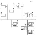
以下、図面を参照して本発明の実施形態について説明する。図1は本発明の実施形態による医用画像表示装置を適用した医療情報システムの概略構成を示す図である。図1に示す医療情報システム1は、公知のオーダリングシステムを用いた診療科の医師からの検査オーダーに基づいて、被写体の検査対象部位の撮影、撮影により取得された医用画像の保管、読影医による医用画像の読影と読影レポートの作成、および依頼元の診療科の医師による読影レポートの閲覧と読影対象の医用画像の詳細観察とを行うためのシステムである。図1に示すように、医療情報システム1は、複数のモダリティ(撮影装置)2、読影端末である複数の読影ワークステーション(WS)3、診療科ワークステーション(WS)4、画像サーバ5、画像データベース6、読影レポートサーバ7、および読影レポートデータベース8が、有線または無線のネットワーク9を介して互いに通信可能な状態で接続されて構成されている。なお、読影WS3に対して、本実施形態の医用画像表示装置が適用されている。
Hereinafter, embodiments of the present invention will be described with reference to the drawings. FIG. 1 is a diagram showing a schematic configuration of a medical information system to which a medical image display device according to an embodiment of the present invention is applied. The medical information system 1 shown in FIG. 1 is based on an examination order from a doctor in a clinical department using a known ordering system, photographs of a part to be inspected of a subject, storage of a medical image acquired by the photography, and an image interpreter. It is a system for interpreting medical images and creating an interpretation report, and for viewing the interpretation report by the doctor of the requesting clinical department and observing the details of the medical image to be interpreted. As shown in FIG. 1, the medical information system 1 includes a plurality of modalities (imaging devices) 2, a plurality of image interpretation workstations (WS) 3 which are image interpretation terminals, a clinical department workstation (WS) 4, an
各機器は、医療情報システム1の構成要素として機能させるためのアプリケーションプログラムがインストールされたコンピュータである。アプリケーションプログラムは、DVD(Digital Versatile Disc)あるいはCD−ROM(Compact Disc Read Only Memory)等の記録媒体に記録されて配布され、その記録媒体からコンピュータにインストールされる。または、ネットワーク9に接続されたサーバコンピュータの記憶装置、もしくはネットワークストレージに、外部からアクセス可能な状態で記憶され、要求に応じてコンピュータにダウンロードされ、インストールされる。
Each device is a computer in which an application program for functioning as a component of the medical information system 1 is installed. The application program is recorded and distributed on a recording medium such as a DVD (Digital Versatile Disc) or a CD-ROM (Compact Disc Read Only Memory), and is installed in the computer from the recording medium. Alternatively, it is stored in the storage device of the server computer connected to the
モダリティ2は、被写体の診断対象となる部位を撮影することにより、診断対象部位を表す医用画像を生成する装置である。具体的には、単純X線撮影装置、CT装置、MRI装置、およびPET(Positron Emission Tomography)装置等である。モダリティ2により生成された医用画像は画像サーバ5に送信され、保存される。
読影WS3は、本実施形態による医用画像表示装置を内包する。読影WS3の構成については後述する。 The image interpretation WS3 includes a medical image display device according to the present embodiment. The configuration of the interpretation WS3 will be described later.
診療科WS4は、診療科の医師が画像の詳細観察、読影レポートの閲覧、および電子カルテの作成等に利用するコンピュータであり、処理装置、高精細ディスプレイ、並びにキーボードおよびマウス等の入力装置により構成される。診療科WS4では、画像サーバ5に対する画像の閲覧要求、画像サーバ5から受信した画像の表示、画像中の病変らしき部分の自動検出または強調表示、読影レポートサーバ7に対する読影レポートの閲覧要求、および読影レポートサーバ7から受信した読影レポートの表示等の各処理が、各処理のためのソフトウェアプログラムを実行することにより行われる。
The clinical department WS4 is a computer used by doctors in the clinical department for detailed observation of images, viewing of interpretation reports, creation of electronic medical records, etc., and is composed of a processing device, a high-definition display, and an input device such as a keyboard and a mouse. Will be done. In the medical department WS4, the
画像サーバ5は、汎用の比較的処理能力の高いコンピュータにデータベース管理システム(DataBase Management System: DBMS)の機能を提供するソフトウェアプログラムがインストールされたものである。また、画像サーバ5は画像データベース6が構成される大容量ストレージを備えている。このストレージは、画像サーバ5とデータバスとによって接続された大容量のハードディスク装置であってもよいし、ネットワーク9に接続されているNAS(Network Attached Storage)およびSAN(Storage Area Network)に接続されたディスク装置であってもよい。また、画像サーバ5は、モダリティ2からの医用画像の登録要求を受け付けると、その医用画像をデータベース用のフォーマットに整えて画像データベース6に登録する。
The
画像データベース6には、モダリティ2において取得された医用画像の画像データと付帯情報とが登録される。付帯情報には、例えば、個々の医用画像を識別するための画像ID、被写体を識別するための患者ID(identification)、検査を識別するための検査ID、医用画像毎に割り振られるユニークなID(UID:unique identification)、その医用画像が生成された検査日、検査時刻、その医用画像を取得するための検査で使用されたモダリティの種類、患者氏名、年齢、性別等の患者情報、検査部位(撮影部位)、撮影情報(撮影プロトコル、撮影シーケンス、撮像手法、撮影条件、造影剤の使用等)、1回の検査で複数の医用画像を取得したときのシリーズ番号あるいは採取番号等の情報が含まれる。
The image data and incidental information of the medical image acquired in the
また、画像サーバ5は、読影WS3からの閲覧要求をネットワーク9経由で受信すると、画像データベース6に登録されている医用画像を検索し、検索された医用画像を要求元の読影WS3に送信する。
When the
読影レポートサーバ7には、汎用のコンピュータにデータベース管理システムの機能を提供するソフトウェアプログラムが組み込まれる。読影レポートサーバ7は、読影WS3からの読影レポートの登録要求を受け付けると、その読影レポートをデータベース用のフォーマットに整えて読影レポートデータベース8に登録する。また、読影レポートの検索要求を受け付けると、その読影レポートを読影レポートデータベース8から検索する。
The
読影レポートデータベース8には、例えば、読影対象の医用画像を識別する画像ID、読影を行った画像診断医を識別するための読影医ID、病変名、病変の位置情報、所見、および所見の確信度等の情報が記録された読影レポートが登録される。
The image
ネットワーク9は、病院内の各種機器を接続する有線または無線のローカルエリアネットワークである。読影WS3が他の病院あるいは診療所に設置されている場合には、ネットワーク9は、各病院のローカルエリアネットワーク同士をインターネットまたは専用回線で接続した構成としてもよい。いずれの場合にも、ネットワーク9は光ネットワーク等の医用画像の高速転送が実現可能な構成にすることが好ましい。
The
以下、本実施形態による読影WS3について詳細に説明する。読影WS3は、医用画像の読影医が、医用画像の読影および読影レポートの作成に利用するコンピュータであり、処理装置、高精細ディスプレイ、並びにキーボードおよびマウス等の入力装置により構成される。読影WS3では、画像サーバ5に対する医用画像の閲覧要求、画像サーバ5から受信した医用画像に対する各種画像処理、医用画像の表示、医用画像に対する解析処理、解析結果に基づく医用画像の強調表示、解析結果に基づく読影レポートの作成、読影レポートの作成の支援、読影レポートサーバ7に対する読影レポートの登録要求と閲覧要求、並びに読影レポートサーバ7から受信した読影レポートの表示等の各処理が、各処理のためのソフトウェアプログラムを実行することにより行われる。なお、これらの処理のうち、本実施形態の医用画像表示装置が行う処理以外の処理は、周知のソフトウェアプログラムにより行われるため、ここでは詳細な説明は省略する。また、本実施形態の医用画像表示装置が行う処理以外の処理を読影WS3において行わず、別途その処理を行うコンピュータをネットワーク9に接続しておき、読影WS3からの処理の要求に応じて、そのコンピュータにおいて要求された処理を行うようにしてもよい。
Hereinafter, the interpretation WS3 according to the present embodiment will be described in detail. The image interpretation WS3 is a computer used by a medical image interpretation doctor to interpret a medical image and create an image interpretation report, and is composed of a processing device, a high-definition display, and an input device such as a keyboard and a mouse. In the interpretation WS3, the
読影WS3は、本実施形態による医用画像表示装置が内包されてなる。このため、読影WS3には、本実施形態による医用画像表示プログラムがインストールされてなる。医用画像表示プログラムは、DVDあるいはCD−ROM等の記録媒体に記録されて配布され、その記録媒体から読影WS3にインストールされる。または、ネットワークに接続されたサーバコンピュータの記憶装置、もしくはネットワークストレージに、外部からアクセス可能な状態で記憶され、要求に応じて読影WS3にダウンロードされ、インストールされる。 The image interpretation WS3 includes a medical image display device according to the present embodiment. Therefore, the medical image display program according to the present embodiment is installed in the image interpretation WS3. The medical image display program is recorded and distributed on a recording medium such as a DVD or a CD-ROM, and is installed in the interpretation WS3 from the recording medium. Alternatively, it is stored in the storage device of the server computer connected to the network or in the network storage in a state where it can be accessed from the outside, and is downloaded and installed in the interpretation WS3 as requested.
図2は、医用画像表示プログラムをインストールすることにより実現される、本発明の第1の実施形態による医用画像表示装置の概略構成を示す図である。図2に示すように、医用画像表示装置10は、標準的なコンピュータの構成として、CPU(Central Processing Unit)11、メモリ12およびストレージ13を備えている。また、医用画像表示装置10には、高精細な液晶ディスプレイ等のディスプレイ14、並びにキーボードおよびマウス等の入力装置(以下、入力部とする)15が接続されている。なお、ディスプレイ14が表示部に対応する。
FIG. 2 is a diagram showing a schematic configuration of a medical image display device according to the first embodiment of the present invention, which is realized by installing a medical image display program. As shown in FIG. 2, the medical
ストレージ13は、ハードディスクまたはSSD(Solid State Drive)等のストレージデバイスからなる。ストレージ13には、ネットワーク9を経由して画像サーバ5から取得した、医用画像および医用画像表示装置10の処理に必要な情報を含む各種情報が記憶されている。
The
また、メモリ12には、医用画像表示プログラムが記憶されている。医用画像表示プログラムは、CPU11に実行させる処理として、疾患を含む医用画像を解析して疾患に関する解析結果を生成する解析処理、解析結果に基づいて疾患に関する記載を含む読影レポートを生成する読影レポート生成処理、医用画像および読影レポートをディスプレイ14に表示する表示制御処理、医用画像における疾患領域および読影レポートにおける疾患に関する記載のいずれか一方に対する修正指示に応じて、医用画像における疾患領域および読影レポートにおける疾患に関する記載の他方を修正する修正処理を規定する。
Further, the
そして、CPU11が医用画像表示プログラムに従いこれらの処理を実行することで、コンピュータは、解析部21、読影レポート作成部22、表示制御部23および修正部24として機能する。なお、本実施形態においては、CPU11が医用画像表示プログラムによって、各部の機能を実行するようにしたが、ソフトウェアを実行して各種の処理部として機能する汎用的なプロセッサとしては、CPU11の他、FPGA (Field Programmable Gate Array)等の製造後に回路構成を変更可能なプロセッサであるプログラマブルロジックデバイス(Programmable Logic Device:PLD)を用いることができる。また、ASIC(Application Specific Integrated Circuit)等の特定の処理を実行させるために専用に設計された回路構成を有するプロセッサである専用電気回路等により、各部の処理を実行するようにしてもよい。
Then, when the
1つの処理部は、これら各種のプロセッサのうちの1つで構成されてもよいし、同種または異種の2つ以上のプロセッサの組み合わせ(例えば、複数のFPGA、またはCPUとFPGAの組み合わせ等)で構成されてもよい。また、複数の処理部を1つのプロセッサで構成してもよい。複数の処理部を1つのプロセッサで構成する例としては、第1に、クライアントやサーバ等のコンピュータに代表されるように、1つ以上のCPUとソフトウェアの組み合わせで1つのプロセッサを構成し、このプロセッサが複数の処理部として機能する形態がある。第2に、システムオンチップ(System On Chip:SoC)などに代表されるように、複数の処理部を含むシステム全体の機能を1つのIC(Integrated Circuit)チップで実現するプロセッサを使用する形態がある。このように、各種の処理部は、ハードウェア的な構造として、上記各種のプロセッサを1つ以上用いて構成される。 One processing unit may be composed of one of these various processors, or may be a combination of two or more processors of the same type or different types (for example, a plurality of FPGAs or a combination of a CPU and an FPGA). It may be configured. Further, a plurality of processing units may be configured by one processor. As an example of configuring a plurality of processing units with one processor, first, one processor is configured by a combination of one or more CPUs and software, as represented by a computer such as a client or a server. There is a form in which a processor functions as a plurality of processing units. Secondly, as typified by System On Chip (SoC), there is a form in which a processor that realizes the functions of the entire system including a plurality of processing units with one IC (Integrated Circuit) chip is used. be. As described above, the various processing units are configured by using one or more of the above-mentioned various processors as a hardware-like structure.
さらに、これらの各種のプロセッサのハードウェア的な構造は、より具体的には、半導体素子等の回路素子を組み合わせた電気回路(circuitry)である。 Further, the hardware structure of these various processors is, more specifically, an electric circuit (circuitry) in which circuit elements such as semiconductor elements are combined.
解析部21は、医用画像を解析して医用画像に含まれる疾患に関する解析結果を取得する。このために、解析部21は、医用画像中の疾患領域を抽出する解析処理を行う。なお、本実施形態においては、医用画像は脳のMRI画像であるとするが、CT画像であってもよい。また、本実施形態においては、解析部21は、梗塞領域の脳内における解剖学的な位置、サイズ、梗塞のタイプ(超急性期か陳旧性か)、およびあるタイプの梗塞であることの確信度を判定する。さらに、解析部21は、医用画像に対する解析結果に基づいて、読影レポートに記載すべき文字情報を生成する。例えば、脳内の部位aに10立方センチメートルの超急性期の梗塞領域30が信頼度0.9にて抽出された場合、文字情報として、「部位a」、「10cm3」、「超急性期の梗塞」、「信頼度0.9」を生成する。また、脳内の部位bに5立方センチメートルの陳旧性の梗塞領域が信頼度0.6にて抽出された場合、文字情報として、「部位b」、「5cm3」、「陳旧性の梗塞」、「信頼度0.6」を生成する。なお、本実施形態においては、解析部21は、梗塞領域の脳内における解剖学的な位置、サイズ、梗塞のタイプ(超急性期か陳旧性か)、およびあるタイプの梗塞であることの確信度、並びにこれらの文字情報を解析結果として取得するものとする。
The
なお、解析部21は、医用画像における各画素(ボクセル)が梗塞領域であるか否か、および梗塞領域のタイプを判別するように機械学習がなされた判別器を備える。本実施形態においては、判別器は、医用画像に含まれる複数種類の病変領域を分類できるようにディープラーニング(深層学習)がなされたニューラルネットワークからなる。判別器は、医用画像が入力されると、医用画像内の各画素(ボクセル)が、超急性期の梗塞であることの確率および陳旧性の梗塞であることの確率を出力するように学習がなされる。そして判別器は、ある画素について出力した確率があらかじめ定められたしきい値以上となる場合に、その画素をしきい値以上となった確率となったタイプの梗塞であると判別する。
The
また、解析部21は、あるタイプの梗塞について、判別器が出力した確率がしきい値以上となった領域内の全画素における、判別器が出力した確率の統計値(例えば平均値、最頻値または最大値等)を、その領域についてのあるタイプの梗塞であることの確信度として算出する。また、解析部21は、あるタイプの梗塞の領域(以下、単に梗塞領域とする)と判別された画素からなる領域に含まれる画素数に、医用画像における1画素当たりの体積を乗算することにより、梗塞領域のサイズを算出する。なお、梗塞領域のサイズの単位は立方センチメートルとする。
In addition, the
読影レポート作成部22は、解析部21の解析結果に基づいて、疾患に関する読影レポートを作成する。読影レポート作成部22は、解析部21が生成した文字情報を文章化するように機械学習がなされており、解析部21が生成した文字情報が入力されると、医用画像の読影レポートの文章を作成する。例えば、文字情報として、「部位a」、「10立方センチメートル」、「超急性期の梗塞」、「信頼度0.9」が入力されると、「部位aに超急性期の梗塞あり、サイズ=10cm3、確信度=0.9」の文章を作成する。また、文字情報として「部位b」、「5cm3」、「陳旧性の梗塞」、「信頼度0.6」が入力されると、「部位bに陳旧性の梗塞あり、サイズ=5cm3、確信度=0.6」の文章を作成する。なお、本実施形態においては、読影レポート作成部22も、文字情報から読影レポートを作成するようにディープラーニング(深層学習)がなされたニューラルネットワークからなる。
The interpretation
なお、読影レポート作成部22は、文字情報として「陳旧性の梗塞」が入力された場合、読影レポートを作成中の医用画像を取得した患者についての過去の読影レポートを検索する指示を読影レポートサーバ7に対して行う。読影レポートサーバ7はこの指示に基づいて読影レポートデータベース8を検索する。過去の読影レポートが検索されると、読影レポートサーバ7は過去の読影レポートの保存場所を表すリンク情報を読影WS3に送信する。なお、過去の読影レポートには、その読影レポートの作成時に参照した過去の医用画像へのリンクが含まれる。読影レポート作成部22は、作成した文章のうち、「陳旧性の梗塞」の文字情報を含む文章に対して、読影レポートサーバ7から送信されたリンクを設定する。
In addition, when "old-fashioned infarction" is input as text information, the interpretation
また、判別器および読影レポート作成部22は、ディープラーニングがなされたニューラルネットワークの他、サポートベクタマシン(SVM(Support Vector Machine))等を用いることができる。
Further, the discriminator and the interpretation
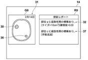
表示制御部23は、医用画像および読影レポートをディスプレイ14に表示する。図3は、第1の実施形態においてディスプレイ14に表示された医用画像および読影レポートを示す図である。図3に示すように、ディスプレイ14には、医用画像G0および読影レポートR0が表示される。医用画像G0においては、解析部21により抽出された梗塞領域30,31が強調表示されている。図3においては強調表示は領域に斜線を付与することにより示されている。また、医用画像G0には撮影日が重畳表示されている。また、読影レポートR0には、疾患に関する記載を含む、「部位aに超急性期の梗塞あり、サイズ=10cm3、確信度=0.9」の文章32、および「部位bに陳旧性の梗塞あり、サイズ=5cm3、確信度=0.6」の文章33が含まれる。さらに、文章33にはリンクが設定されていることを示す下線が付与されている。
The
操作者はリンクが設定された文章33を入力部15を用いて指示することにより、患者の過去の読影レポートを読影レポートデータベース8から、過去の読影レポートに関連付けられた過去の医用画像を画像データベース6からそれぞれダウンロードしてディスプレイ14に表示することができる。図4はディスプレイ14に表示された過去の医用画像および過去の読影レポートを示す図である。図4に示すように、ディスプレイ14には、過去の医用画像G1および過去の読影レポートR1がそれぞれ表示される。過去の医用画像G1においては、部位bにおいて梗塞領域34が強調表示されている。なお、梗塞領域34は図3における梗塞領域30と梗塞のタイプが同一であるため、梗塞領域34には梗塞領域30と同一の斜線が付与されている。また、過去の読影レポートR1には、疾患に関する記載を含む、「部位bに超急性期の梗塞あり、サイズ=5cm3、確信度=0.6」の文章35が含まれる。
By instructing the
修正部24は、医用画像G0における疾患領域および読影レポートR0における疾患に関する記載のいずれか一方に対する入力部15を用いての操作者による修正指示に応じて、医用画像G0における疾患領域および読影レポートR0における疾患に関する記載の他方を修正する。すなわち、修正部24は、医用画像G0における疾患領域に対する修正指示に応じて、読影レポートR0における疾患に関する記載を修正する。また、読影レポートR0における疾患に関する記載に対する修正指示に応じて、医用画像G0における疾患領域を修正する。
The
図5および図6は第1の実施形態における修正処理を説明するための図である。なお、図5においては医用画像G0において梗塞領域30のみが強調表示され、読影レポートR0には文章32のみが含まれているものとする。そして、図5に示すように、医用画像G0に対して疾患領域として部位cに梗塞領域36を追加する修正指示が入力部15からなされたとする。これにより、修正部24は、「部位cに超急性期の梗塞あり」の文章37を作成して、図6に示すように読影レポートR0に追加する。ここで、文章37には手動で追加されたことを表す「手動追加」の文字が表示される。なお、医用画像G0に対する梗塞領域の追加の指示のみではその梗塞領域のタイプが超急性期か陳旧性か不明である。本実施形態においては、修正部24は初期表示として「超急性期」の文字を使用して、「部位cに超急性期の梗塞あり」の文章を作成する。なお、梗塞領域36が陳旧性である場合、操作者は文章37に含まれる「超急性期」を「陳旧性」に修正すればよい。
5 and 6 are diagrams for explaining the correction process in the first embodiment. In FIG. 5, it is assumed that only the
なお、逆に読影レポートR0に対して、操作者が「部位cに超急性期の梗塞あり」の文章37を追加する修正指示を行った場合、修正部24は、医用画像G0の部位cにおいて、超急性期の梗塞領域36を設定し、梗塞領域36を強調表示する。
On the contrary, when the operator gives a correction instruction to the interpretation report R0 to add the
次いで、第1の実施形態において行われる処理について説明する。図7は本実施形態において行われる処理を示すフローチャートである。画像サーバ5に対して新たな医用画像が保存されたことの通知を読影WS3、すなわち医用画像表示装置10が受信することにより処理が開始され、医用画像表示装置10の解析部21により、画像サーバ5から医用画像G0が取得され(ステップST1)、解析部21が、医用画像G0を解析して解析結果を取得する(ステップST2)。そして、読影レポート作成部22が、解析結果に基づいて、疾患に関する読影レポートR0を作成する(ステップST3)。次いで、表示制御部23が、医用画像G0および読影レポートR0をディスプレイ14に表示する(ステップST4)。
Next, the processing performed in the first embodiment will be described. FIG. 7 is a flowchart showing the processing performed in the present embodiment. Processing is started when the image interpretation WS3, that is, the medical
続いて、修正部24が、医用画像G0における疾患領域および読影レポートR0における疾患に関する記載のいずれか一方に対する修正指示がなされたか否かを判定する(ステップST5)。ステップST5が否定されるとステップST8の処理に進む。ステップST5が肯定されると、修正指示に応じて医用画像G0における疾患領域および読影レポートR0における疾患に関する記載の他方を修正する(ステップST6)。表示制御部23は、修正された医用画像G1または読影レポートR1を表示する(ステップST7)。続いて、終了の指示がなされたか否かが判定され(ステップST8)、ステップST8が否定されるとステップST5の処理に戻る。ステップST8が肯定されると、処理を終了する。
Subsequently, the
このように、本実施形態においては、疾患領域を含む医用画像G0および疾患に関する記載を含む読影レポートR0をディスプレイ14に表示し、医用画像G0における疾患領域および読影レポートR0における疾患に関する記載のいずれか一方に対する修正指示に応じて、医用画像G0における疾患領域および読影レポートR0における疾患に関する記載の他方を修正するようにした。このため、医用画像G0および読影レポートR0の双方に対する修正が必要な場合であっても、医用画像G0および読影レポートR0のいずれか一方を修正すれば、これに応じて他方が修正されることとなる。このため、医用画像G0および読影レポートR0を修正する操作者(読影医)の負担を軽減することができる。
As described above, in the present embodiment, the medical image G0 including the disease region and the interpretation report R0 including the description regarding the disease are displayed on the
なお、上記第1の実施形態においては、読影レポート作成部22が、所見を含む文章を読影レポートR0として作成しているが、これに限定されるものではなく、ASPECTSを含む読影レポートを作成してもよい。以下、これを第2の実施形態として説明する。なお、第2の実施形態において、医用画像表示装置の構成は図2に示す第1の実施形態による医用画像表示装置と同一であり、行われる処理のみが異なるため、ここでは装置についての詳細な説明は省略する。第2の実施形態においては、医用画像は3次元のCT画像とし、解析部21は、3次元のCT画像に含まれる基底核レベルの断層画像および放射冠レベルの断層画像を解析して、梗塞領域を抽出するように解析を行う。
In the first embodiment, the interpretation
図8はASPECTSを説明するための脳の模式図である。ASPECTSとは、Alberta Stroke Program Early CT Scoreの略語であり、中大脳動脈領域の脳梗塞に対して、単純CTのearly CT signを定量化したスコア法である。具体的には、医用画像がCT画像の場合、中大脳動脈領域を代表的2断面(基底核レベルおよび放線冠レベル)における10領域に分類し、各領域ごとに早期虚血変化の有無を評価し、陽性箇所を減点法で採点する手法である。ASPECTSにおいては、脳の基底核レベルの断層画像S1に対して左右の中大脳動脈領域がそれぞれC、I、L、ICおよびM1〜M3の7領域に分類され、放射冠レベルの断層画像S2に対して左右の中大脳動脈領域がそれぞれM4〜M6の3つの領域に分類されている。なお、図8においては、説明を簡単なものとするために、右脳にのみ領域を示している。第2の実施形態においては、医用画像G0から梗塞領域を抽出し、かつ梗塞領域の上記10領域の位置を特定して、解析結果を生成する。 FIG. 8 is a schematic diagram of the brain for explaining ASPECTS. ASPECTS is an abbreviation for Alberta Stroke Program Early CT Score, and is a scoring method that quantifies the early CT sign of simple CT for cerebral infarction in the middle cerebral artery region. Specifically, when the medical image is a CT image, the middle cerebral artery region is classified into 10 regions in two typical cross sections (basal ganglia level and radial coronary level), and the presence or absence of early ischemic change is evaluated for each region. However, it is a method of scoring positive points by the deduction method. In ASPECTS, the left and right middle cerebral artery regions are classified into 7 regions C, I, L, IC and M1 to M3 with respect to the tomographic image S1 at the basal ganglia level of the brain, and the tomographic image S2 at the corona radiata level. On the other hand, the left and right middle cerebral artery regions are classified into three regions, M4 to M6, respectively. In FIG. 8, for the sake of simplicity, the region is shown only in the right brain. In the second embodiment, the infarcted region is extracted from the medical image G0, the positions of the above 10 regions of the infarcted region are specified, and the analysis result is generated.
第2の実施形態においては、読影レポート作成部22は、ASPECTSを含む読影レポートを作成する。
In the second embodiment, the interpretation
第2の実施形態においては、表示制御部23は、医用画像およびASPECTSを含む読影レポートをディスプレイ14に表示する。図9は第2の実施形態において、ディスプレイ14に表示された医用画像およびASPECTSを含む読影レポートを示す図である。図9に示すように、第2の実施形態においては、医用画像として、脳の基底核レベルの断層画像S11および脳の放射冠レベルの断層画像S12が表示される。なお、断層画像S11,S12は、人体の足側から頭側に向かって脳を見た画像となっている。このため、図9に示す断層画像S11,S12においては、右側が左脳、左側が右脳となっている。また、図9に示すように断層画像S11および断層画像S12には、ASPECTSの10の領域が示されている。また、梗塞を含む領域については強調表示されている。図9においては、強調表示を斜線を付与することにより示している。また、読影レポートR11はASPECTSにおける左右の脳の10領域について梗塞領域を含むか否かについてのチェックおよびASPECTSを含む。ここで、第2の実施形態においては、右脳には梗塞領域が抽出されていないため、いずれの領域も断層画像S11,S12において強調表示されておらず、読影レポートR11のいずれの領域に対してもチェックがなされていない。このため、右脳についてはASPECTSは10点である。また、左脳には領域M5において梗塞領域が抽出されているため、断層画像S12の領域M5が強調表示されており、読影レポートR11の左脳の領域M5にチェックが付与されている。このため、左脳についてはASPECTSは9点である。
In the second embodiment, the
なお、医用画像G0におけるASPECTSの10領域の特定は、医用画像G0と標準脳画像とを位置合わせすることにより行う。標準脳画像とは、標準的な形状および大きさ、並びに標準的な濃度(画素値)を有する脳、すなわち標準脳を表す3次元の脳画像である。標準脳画像は、複数の健常者の頭部を3次元画像撮影装置により取得した複数の脳画像から脳を抽出し、抽出した複数の脳を平均することにより生成することができる。また、標準脳画像は、コンピュータグラフィックス等により作成されたものであってもよい。また、一人の健常者の脳画像を標準脳画像として用いてもよい。 The 10 regions of ASPECTS in the medical image G0 are specified by aligning the medical image G0 with the standard brain image. A standard brain image is a three-dimensional brain image representing a brain having a standard shape and size and a standard density (pixel value), that is, a standard brain. A standard brain image can be generated by extracting brains from a plurality of brain images acquired by a three-dimensional imaging device for the heads of a plurality of healthy subjects and averaging the extracted plurality of brains. Further, the standard brain image may be created by computer graphics or the like. Moreover, you may use the brain image of one healthy person as a standard brain image.
ここで、標準脳画像はASPECTSの10領域に分割されている。第2の実施形態においては、表示制御部23は、医用画像G0と標準脳画像とを位置合わせし、医用画像G0においてASPECTSの10の領域を特定し、表示する断層画像S11,S12において、ASPECTSの10領域を、図9に示すように区分して表示する。
Here, the standard brain image is divided into 10 regions of ASPECTS. In the second embodiment, the
一方、第2の実施形態においても、修正部24は、医用画像G0における疾患領域および読影レポートR0における疾患領域に関する記載のいずれか一方に対する修正指示に応じて、医用画像G0における疾患領域および読影レポートR0における疾患領域に関する記載の他方を修正する。すなわち、第2の実施形態においては、操作者が読影レポートR11を修正すると、断層画像S11,S12が修正される。例えば、図10に示すように、読影レポートR11において右脳の領域M2にチェックを付与すると、修正部24は断層画像S11における右脳の領域M2を強調表示する。一方、断層画像S11における右脳の領域M2を強調表示する指示を行うと、修正部24は、読影レポートR11における右脳の領域M2にチェックを付与する。いずれの場合も、右脳のASPECTSは9点となる。
On the other hand, also in the second embodiment, the
また、操作者は、断層画像S11,S12において、入力部15を用いて梗塞領域を修正することも可能である。図11は第2の実施形態における梗塞領域の修正を説明するための図である。なお、図11は断層画像S12の左脳の領域の一部を拡大して示している。図11に示すように、解析部21による解析処理により梗塞領域38が抽出された場合、図9と同様に断層画像S12において左脳の領域M5が強調表示され、読影レポートR11において左脳の領域M5がチェックされる。しかしながら、読影医が断層画像S12を読影したところ、図11の破線に示すように、領域M4,M5に跨がる梗塞領域38Aが確認できたとする。この場合、読影医は断層画像S12において梗塞領域38を梗塞領域38Aに修正する。修正部24はこの指示により、図12に示すように、断層画像S12において左脳の領域M4,M5を強調表示し、読影レポートR11において左脳の領域M4にさらにチェックを付与する。この結果、左脳のASPECTSは8点となる。
The operator can also correct the infarcted region by using the input unit 15 in the tomographic images S11 and S12. FIG. 11 is a diagram for explaining the modification of the infarcted region in the second embodiment. Note that FIG. 11 shows an enlarged part of the left brain region of the tomographic image S12. As shown in FIG. 11, when the
なお、上記第2の実施形態においては、読影レポートR11にASPECTSを含めているが、ASPECTSに加えて、第1の実施形態と同様の文章を含めてもよい。例えば、「領域M5に超急性期の梗塞領域あり」、というような文章を含めるようにしてもよい。 In the second embodiment, ASPECTS is included in the interpretation report R11, but in addition to ASPECTS, the same sentences as in the first embodiment may be included. For example, a sentence such as "the region M5 has an infarcted region in the hyperacute stage" may be included.
また、上記実施形態においては、読影WS3における医用画像表示装置10が、解析部21および読影レポート作成部22を備えているが、外部の解析サーバまたは読影レポート作成サーバ等において、医用画像の解析および解析結果に基づく読影レポートの作成を行うようにしてもよい。
Further, in the above embodiment, the medical
また、上記実施形態においては、医用画像として脳のCT画像およびMRI画像を用いているが、他の部位の医用画像を用いてもよい。例えば、心拡大の疾患を含む心臓の医用画像を解析して心臓の領域を疾患の領域として抽出し、読影レポートが心胸郭比を含むものとしてもよい。図13はディスプレイ14に表示された心臓の医用画像および読影レポートを示す図である。図13に示すように、ディスプレイ14には心臓の単純X線画像である医用画像G12および読影レポートR12が表示されている。なお、医用画像G12においては胸郭の範囲Aを表す矢印40および心臓の範囲Bを表す矢印41が表示されている。また、読影レポートR12には心胸郭比(B/A×100%)が含まれる。
Further, in the above embodiment, the CT image and the MRI image of the brain are used as the medical images, but the medical images of other parts may be used. For example, a medical image of the heart containing the disease of cardiac enlargement may be analyzed to extract the region of the heart as the region of the disease, and the interpretation report may include the cardiothoracic ratio. FIG. 13 is a diagram showing a medical image of the heart and an interpretation report displayed on the
操作者である読影医は、医用画像G12において、矢印40,41による範囲を修正することができる。また、読影レポートR12において、心胸郭比の値を修正することができる。医用画像G12において矢印40,41が示す範囲が修正されると、修正部24は、心胸郭比を計算し直して、読影レポートR12を修正する。なお、読影レポートR12において心胸郭比が修正された場合、修正部24は、医用画像G12における矢印40,41が示す範囲を修正してもよい。この場合矢印40,41のいずれか一方のみを修正すればよい。
The image interpreter who is the operator can correct the range indicated by the
1 医療情報システム
2 モダリティ
3 読影ワークステーション
4 診療科ワークステーション
5 画像サーバ
6 画像データベース
7 読影レポートサーバ
8 読影レポートデータベース
9 ネットワーク
10 医用画像表示装置
11 CPU
12 メモリ
13 ストレージ
14 ディスプレイ
15 入力部
21 解析部
22 読影レポート作成部
23 表示制御部
24 修正部
30,31,34,36,38,38A 梗塞領域
32,33,35,37 文章
40,41 矢印
G0,G1,G12 医用画像
R0,R1,R11,R12 読影レポート
S1,S2,S11,S12 断層画像
1
12
Claims (13)
前記医用画像における前記疾患の領域に対する修正指示に応じて、前記読影レポートにおける前記疾患に関する記載を修正する修正部とを備えた医用画像表示装置。 A display control unit that displays a medical image including a disease and an interpretation report including a description of the disease on the display unit.
In response to said correction instruction against the area of the disease in the medical image, the medical image display apparatus that includes a correcting unit for correcting the description of the disease before Symbol interpretation report.
前記医用画像における前記疾患の領域に対する修正指示に応じて、前記読影レポートにおける前記疾患に関する記載を修正する医用画像表示方法。 The computer displays a medical image containing the disease and an interpretation report containing a description of the disease on the display.
In response to said correction instruction against the area of the disease in medical images, medical image display method for modifying a description of the disease before Symbol interpretation report.
前記医用画像における前記疾患の領域に対する修正指示に応じて、前記読影レポートにおける前記疾患に関する記載を修正する手順とをコンピュータに実行させる医用画像表示プログラム。 A procedure for displaying a medical image including a disease and an interpretation report including a description of the disease on the display unit, and
In response to said correction instruction against the area of the disease in medical images, medical image display program for executing the procedure for modifying a description of the disease before Symbol interpretation report to the computer.
Priority Applications (2)
| Application Number | Priority Date | Filing Date | Title |
|---|---|---|---|
| JP2018035200A JP6906462B2 (en) | 2018-02-28 | 2018-02-28 | Medical image display devices, methods and programs |
| US16/235,154 US11139067B2 (en) | 2018-02-28 | 2018-12-28 | Medical image display device, method, and program |
Applications Claiming Priority (1)
| Application Number | Priority Date | Filing Date | Title |
|---|---|---|---|
| JP2018035200A JP6906462B2 (en) | 2018-02-28 | 2018-02-28 | Medical image display devices, methods and programs |
Publications (3)
| Publication Number | Publication Date |
|---|---|
| JP2019149130A JP2019149130A (en) | 2019-09-05 |
| JP2019149130A5 JP2019149130A5 (en) | 2020-03-05 |
| JP6906462B2 true JP6906462B2 (en) | 2021-07-21 |
Family
ID=67686046
Family Applications (1)
| Application Number | Title | Priority Date | Filing Date |
|---|---|---|---|
| JP2018035200A Active JP6906462B2 (en) | 2018-02-28 | 2018-02-28 | Medical image display devices, methods and programs |
Country Status (2)
| Country | Link |
|---|---|
| US (1) | US11139067B2 (en) |
| JP (1) | JP6906462B2 (en) |
Cited By (2)
| Publication number | Priority date | Publication date | Assignee | Title |
|---|---|---|---|---|
| US11501437B1 (en) * | 2022-04-28 | 2022-11-15 | Qure.Ai Technologies Private Limited | Monitoring brain CT scan image |
| US11636596B1 (en) | 2022-04-28 | 2023-04-25 | Qure.Ai Technologies Private Limited | Monitoring brain CT scan image |
Families Citing this family (6)
| Publication number | Priority date | Publication date | Assignee | Title |
|---|---|---|---|---|
| EP3657435A1 (en) * | 2018-11-26 | 2020-05-27 | Koninklijke Philips N.V. | Apparatus for identifying regions in a brain image |
| US11694332B2 (en) * | 2018-12-21 | 2023-07-04 | The Trustees Of Indiana University | Active bleeding measurement |
| JP7234364B2 (en) * | 2019-06-28 | 2023-03-07 | 富士フイルム株式会社 | MEDICAL IMAGE PROCESSING APPARATUS, METHOD AND PROGRAM |
| WO2021112141A1 (en) * | 2019-12-03 | 2021-06-10 | 富士フイルム株式会社 | Document creation assistance device, method, and program |
| WO2021177312A1 (en) * | 2020-03-03 | 2021-09-10 | 富士フイルム株式会社 | Device, method, and program for storing information, and device, method, and program for generating analysis records |
| US20230129056A1 (en) * | 2021-10-25 | 2023-04-27 | Canon Medical Systems Corporation | Medical image data processing apparatus and method |
Family Cites Families (16)
| Publication number | Priority date | Publication date | Assignee | Title |
|---|---|---|---|---|
| JP2005148990A (en) * | 2003-11-13 | 2005-06-09 | Konica Minolta Medical & Graphic Inc | Medical image interpretation system and interpretation report creating method |
| JP4389011B2 (en) * | 2004-04-07 | 2009-12-24 | 国立大学法人名古屋大学 | MEDICAL REPORT CREATION DEVICE, MEDICAL REPORT CREATION METHOD, AND PROGRAM THEREOF |
| US7689016B2 (en) * | 2005-05-27 | 2010-03-30 | Stoecker & Associates, A Subsidiary Of The Dermatology Center, Llc | Automatic detection of critical dermoscopy features for malignant melanoma diagnosis |
| JP2007287027A (en) * | 2006-04-19 | 2007-11-01 | Fujifilm Corp | Medical planning support system |
| JP5003098B2 (en) * | 2006-10-25 | 2012-08-15 | 富士ゼロックス株式会社 | Document editing support system, document editing support method, and document editing support program |
| JP2009238038A (en) | 2008-03-27 | 2009-10-15 | Fujifilm Corp | Medical report system, medical report browse device, medical report program, and method of browsing medical report |
| JP5203858B2 (en) * | 2008-09-01 | 2013-06-05 | 富士フイルム株式会社 | MEDICAL IMAGE DISPLAY DEVICE, MEDICAL IMAGE DISPLAY METHOD, AND MEDICAL IMAGE DISPLAY PROGRAM |
| JP2015095043A (en) * | 2013-11-11 | 2015-05-18 | 株式会社東芝 | Medical report apparatus and medical report processing method |
| JP2015150403A (en) | 2014-02-10 | 2015-08-24 | 株式会社 中居木工 | Lift transfer support device |
| US20160203263A1 (en) * | 2015-01-08 | 2016-07-14 | Imbio | Systems and methods for analyzing medical images and creating a report |
| JP6579849B2 (en) * | 2015-07-31 | 2019-09-25 | キヤノン株式会社 | Interpretation report creation support system, interpretation report creation support method, and interpretation report creation support program |
| JP6532371B2 (en) | 2015-10-02 | 2019-06-19 | オリンパス株式会社 | Medical report creation support system |
| US9589374B1 (en) * | 2016-08-01 | 2017-03-07 | 12 Sigma Technologies | Computer-aided diagnosis system for medical images using deep convolutional neural networks |
| US10340046B2 (en) * | 2016-10-27 | 2019-07-02 | Progenics Pharmaceuticals, Inc. | Network for medical image analysis, decision support system, and related graphical user interface (GUI) applications |
| GB201717397D0 (en) * | 2017-10-23 | 2017-12-06 | Brainomix Ltd | Tomographic data analysis |
| JP2021515240A (en) * | 2018-04-12 | 2021-06-17 | グーグル エルエルシーGoogle LLC | Augmented reality microscope for pathology with overlay of quantitative biomarker data |
-
2018
- 2018-02-28 JP JP2018035200A patent/JP6906462B2/en active Active
- 2018-12-28 US US16/235,154 patent/US11139067B2/en active Active
Cited By (2)
| Publication number | Priority date | Publication date | Assignee | Title |
|---|---|---|---|---|
| US11501437B1 (en) * | 2022-04-28 | 2022-11-15 | Qure.Ai Technologies Private Limited | Monitoring brain CT scan image |
| US11636596B1 (en) | 2022-04-28 | 2023-04-25 | Qure.Ai Technologies Private Limited | Monitoring brain CT scan image |
Also Published As
| Publication number | Publication date |
|---|---|
| JP2019149130A (en) | 2019-09-05 |
| US20190267132A1 (en) | 2019-08-29 |
| US11139067B2 (en) | 2021-10-05 |
Similar Documents
| Publication | Publication Date | Title |
|---|---|---|
| JP6906462B2 (en) | Medical image display devices, methods and programs | |
| JP2019153250A (en) | Device, method, and program for supporting preparation of medical document | |
| US8934687B2 (en) | Image processing device, method and program including processing of tomographic images | |
| JP2019169049A (en) | Medical image specification device, method, and program | |
| JP7000206B2 (en) | Medical image processing equipment, medical image processing methods, and medical image processing programs | |
| US11468659B2 (en) | Learning support device, learning support method, learning support program, region-of-interest discrimination device, region-of-interest discrimination method, region-of-interest discrimination program, and learned model | |
| JP7086759B2 (en) | Diagnostic support device, diagnostic support method, and diagnostic support program | |
| JP2019149005A (en) | Medical document creation support apparatus, method, and program | |
| WO2019193982A1 (en) | Medical document creation assistance device, medical document creation assistance method, and medical document creation assistance program | |
| JP7237089B2 (en) | MEDICAL DOCUMENT SUPPORT DEVICE, METHOD AND PROGRAM | |
| JP2024009342A (en) | Document preparation supporting device, method, and program | |
| WO2019102917A1 (en) | Radiologist determination device, method, and program | |
| JP7007469B2 (en) | Medical document creation support devices, methods and programs, trained models, and learning devices, methods and programs | |
| JP7109345B2 (en) | Priority determination device, method and program | |
| WO2019193983A1 (en) | Medical document display control device, medical document display control method, and medical document display control program | |
| JP7431317B2 (en) | Document creation support device, method and program | |
| JP7064430B2 (en) | Priority determination device, method and program | |
| JP7376715B2 (en) | Progress prediction device, method of operating the progress prediction device, and progress prediction program | |
| US20230121783A1 (en) | Medical image processing apparatus, method, and program | |
| WO2022215530A1 (en) | Medical image device, medical image method, and medical image program | |
| JP7371220B2 (en) | Information processing device, information processing method, and information processing program | |
| JP7209738B2 (en) | Image analysis device, analysis function determination method, and analysis function determination program | |
| WO2022239593A1 (en) | Document creation assistance device, document creation assistance method, and document creation assistance program | |
| WO2022224848A1 (en) | Document creation assistance device, document creation assistance method, and document creation assistance program | |
| WO2022070528A1 (en) | Medical image processing device, method, and program |
Legal Events
| Date | Code | Title | Description |
|---|---|---|---|
| A521 | Request for written amendment filed |
Free format text: JAPANESE INTERMEDIATE CODE: A523 Effective date: 20200123 |
|
| A621 | Written request for application examination |
Free format text: JAPANESE INTERMEDIATE CODE: A621 Effective date: 20200123 |
|
| A977 | Report on retrieval |
Free format text: JAPANESE INTERMEDIATE CODE: A971007 Effective date: 20200722 |
|
| A131 | Notification of reasons for refusal |
Free format text: JAPANESE INTERMEDIATE CODE: A131 Effective date: 20201222 |
|
| A521 | Request for written amendment filed |
Free format text: JAPANESE INTERMEDIATE CODE: A523 Effective date: 20210216 |
|
| TRDD | Decision of grant or rejection written | ||
| A01 | Written decision to grant a patent or to grant a registration (utility model) |
Free format text: JAPANESE INTERMEDIATE CODE: A01 Effective date: 20210608 |
|
| A61 | First payment of annual fees (during grant procedure) |
Free format text: JAPANESE INTERMEDIATE CODE: A61 Effective date: 20210629 |
|
| R150 | Certificate of patent or registration of utility model |
Ref document number: 6906462 Country of ref document: JP Free format text: JAPANESE INTERMEDIATE CODE: R150 |