JP6904005B2 - Battery control method, battery system and uninterruptible power supply - Google Patents
Battery control method, battery system and uninterruptible power supply Download PDFInfo
- Publication number
- JP6904005B2 JP6904005B2 JP2017068141A JP2017068141A JP6904005B2 JP 6904005 B2 JP6904005 B2 JP 6904005B2 JP 2017068141 A JP2017068141 A JP 2017068141A JP 2017068141 A JP2017068141 A JP 2017068141A JP 6904005 B2 JP6904005 B2 JP 6904005B2
- Authority
- JP
- Japan
- Prior art keywords
- storage battery
- battery
- storage
- assembled battery
- control unit
- Prior art date
- Legal status (The legal status is an assumption and is not a legal conclusion. Google has not performed a legal analysis and makes no representation as to the accuracy of the status listed.)
- Active
Links
Images


Classifications
-
- Y—GENERAL TAGGING OF NEW TECHNOLOGICAL DEVELOPMENTS; GENERAL TAGGING OF CROSS-SECTIONAL TECHNOLOGIES SPANNING OVER SEVERAL SECTIONS OF THE IPC; TECHNICAL SUBJECTS COVERED BY FORMER USPC CROSS-REFERENCE ART COLLECTIONS [XRACs] AND DIGESTS
- Y02—TECHNOLOGIES OR APPLICATIONS FOR MITIGATION OR ADAPTATION AGAINST CLIMATE CHANGE
- Y02E—REDUCTION OF GREENHOUSE GAS [GHG] EMISSIONS, RELATED TO ENERGY GENERATION, TRANSMISSION OR DISTRIBUTION
- Y02E60/00—Enabling technologies; Technologies with a potential or indirect contribution to GHG emissions mitigation
- Y02E60/10—Energy storage using batteries
Landscapes
- Charge And Discharge Circuits For Batteries Or The Like (AREA)
- Secondary Cells (AREA)
Description
本発明は、複数の二次電池が直列接続された構成の組電池の制御方法、組電池を含む組電池システム、および無停電電源装置に関する。 The present invention relates to a method for controlling an assembled battery having a configuration in which a plurality of secondary batteries are connected in series, an assembled battery system including the assembled battery, and an uninterruptible power supply.
複数の二次電池(蓄電池)が直列接続された構成の組電池を使用した無停電電源装置が使用されている。 An uninterruptible power supply that uses an assembled battery in which a plurality of secondary batteries (storage batteries) are connected in series is used.
一般に、組電池において、初期故障、またはその後の偶発故障が生じた場合には、組電池全体が良品に交換される。また、期待寿命が10年程度であったとしても、経時劣化に起因して、10年経過前に組電池の更新が行われることもある。 Generally, in the case of an initial failure or a subsequent accidental failure in the assembled battery, the entire assembled battery is replaced with a non-defective product. Further, even if the expected life is about 10 years, the assembled battery may be renewed before 10 years have passed due to deterioration over time.
組電池において生じた故障等の原因が、複数の蓄電池からなる蓄電池群における1つまたは少数の蓄電池であったときには、他の蓄電池は正常である。しかし、そのような場合でも、一般に、組電池全体が交換される。また、組電池の更新の際には、組電池全体が交換される。 When the cause of the failure or the like occurring in the assembled battery is one or a small number of storage batteries in the storage battery group consisting of a plurality of storage batteries, the other storage batteries are normal. However, even in such a case, the entire assembled battery is generally replaced. Further, when the assembled battery is renewed, the entire assembled battery is replaced.
稼働する蓄電池群の他に、予備の蓄電池が備えられている組電池がある(例えば、特許文献1,2参照)。特許文献1,2に記載されている組電池において、蓄電池群におけるある蓄電池の異常が検知されると、その蓄電池が蓄電池群から切り離され、予備の蓄電池が蓄電池群に加えられる。
In addition to the operating storage battery group, there is an assembled battery provided with a spare storage battery (see, for example,
しかし、特許文献1,2に記載されている組電池に対して、予備の蓄電池の劣化は考慮されていない。特許文献1に記載されている発明では、予備の蓄電池の劣化が検出されると、予備の蓄電池を蓄電池群に加えない制御がなされる。しかし、予備の蓄電池の劣化に対する対策は考慮されていない。
However, the deterioration of the spare storage battery is not taken into consideration with respect to the assembled batteries described in
本発明は、予備の蓄電池を備える組電池の全体的な寿命を延ばすことを目的とする。 An object of the present invention is to extend the overall life of an assembled battery including a spare storage battery.
本発明による組電池の制御方法は、所望の電圧を出力するための数よりも多い数の蓄電池が直列配置された組電池の制御方法であって、所望の電圧を出力するために稼働している蓄電池とそれ以外の蓄電池とを交代させることによって、全ての蓄電池に、予備としての蓄電池になる機会を与え、蓄電池が劣化しているか否か判定し、劣化していると判定された蓄電池の予備としての蓄電池になっている期間を、劣化していないと判定された蓄電池の期間よりも長くすることを特徴とする。 The method for controlling an assembled battery according to the present invention is a method for controlling an assembled battery in which a larger number of storage batteries are arranged in series than for outputting a desired voltage, and is operated to output a desired voltage. By replacing the existing storage battery with the other storage batteries, all the storage batteries are given an opportunity to become a spare storage battery, and it is judged whether or not the storage battery is deteriorated. It is characterized in that the period of the storage battery as a spare is made longer than the period of the storage battery determined not to be deteriorated .
本発明による組電池システムは、所望の電圧を出力するための数よりも多い数の蓄電池が直列配置された組電池と、組電池の監視および制御を行う監視制御部とを含む組電池システムであって、監視制御部は、所望の電圧を出力するために稼働している蓄電池とそれ以外の蓄電池とを交代させることによって、全ての蓄電池に、予備としての蓄電池になる機会を与え、監視制御部は、蓄電池が劣化しているか否か判定する手段を含み、劣化していると判定された蓄電池の予備としての蓄電池になっている期間を、劣化していないと判定された蓄電池の期間よりも長くすることを特徴とする。 The assembled battery system according to the present invention is an assembled battery system including an assembled battery in which a larger number of storage batteries than the number for outputting a desired voltage are arranged in series, and a monitoring control unit for monitoring and controlling the assembled batteries. Therefore, the monitoring and control unit gives all the storage batteries an opportunity to become a spare storage battery by replacing the operating storage battery with the other storage batteries to output the desired voltage, and monitors and controls the storage battery. The unit includes a means for determining whether or not the storage battery is deteriorated, and the period during which the storage battery is used as a spare for the storage battery determined to be deteriorated is longer than the period of the storage battery determined to be not deteriorated. It is also characterized by making it longer.
本発明による無停電電源装置は、上記の組電池システムを含むことを特徴とする。 The uninterruptible power supply according to the present invention is characterized by including the above-mentioned assembled battery system.
本発明によれば、予備の蓄電池を備える組電池の全体的な寿命を延ばすことができる。 According to the present invention, the overall life of an assembled battery including a spare storage battery can be extended.
以下、本発明の実施形態を図面を参照して説明する。 Hereinafter, embodiments of the present invention will be described with reference to the drawings.
実施形態1.
図1は、組電池システムの一例を示すブロック図である。組電池システムは、組電池12と、組電池12の監視および制御を行う監視制御部11とを含む。
FIG. 1 is a block diagram showing an example of an assembled battery system. The assembled battery system includes an assembled
組電池12は、蓄電池121,122,123で構成される蓄電池群と、予備の蓄電池124とを含む。
The assembled
また、図1には、蓄電池121,122,123および予備の蓄電池124を充電したり放電させたりする充放電装置13が示されている。充放電装置13は、例えば商用交流電源に接続される。また、充放電装置13は、リレー14を介して蓄電池121,122,123および予備の蓄電池124を充放電する。リレー14は、監視制御部11によって制御される。なお、本実施形態では、蓄電池121,122,123および予備の蓄電池124を別個に充電可能である。
Further, FIG. 1 shows a charging /
なお、図1には、3つの蓄電池121,122,123が例示されているが、蓄電池の個数は3つに限定されず、2つ以上あればよい。また、図1には、1つの予備の蓄電池124が例示されているが、複数の予備の蓄電池があってもよい。換言すれば、組電池12において、所望の電圧を出力するための数よりも多い数の蓄電池が直列配置されていれば、数はいくつであってもよい。
Although three
蓄電池121と蓄電池122とは、スイッチ141を介して直列接続される。蓄電池122と蓄電池123とは、スイッチ142を介して直列接続される。蓄電池123と予備の蓄電池124とは、スイッチ143を介して直列接続される。さらに、予備の蓄電池124は、スイッチ144によって切り離される。
The
スイッチ141,142,143,144の共通端子がオフ(OFF )端子側に接続されると、蓄電池121,122,123または予備の蓄電池124が稼働する蓄電池群に加わり、共通端子がオン(ON)端子側に接続されると、蓄電池121,122,123または予備の蓄電池124が稼働する蓄電池群から切り離される。以下、予備の蓄電池124も稼働する蓄電池になりうるので、予備の蓄電池124を、単に、蓄電池と表現することがある。
When the common terminals of the
稼働する蓄電池群が蓄電池121,122,123で構成されているときには、スイッチ141,142,143の共通端子は、オフ端子側に接続されている。また、スイッチ144の共通端子は、オン端子側に接続されている。
When the operating storage battery group is composed of
なお、蓄電池121の正極側とスイッチ141のオン端子との間の電流路をバイパス部131とする。スイッチ141の共通端子とスイッチ142のオン端子との間の電流路をバイパス部132とする。スイッチ142の共通端子とスイッチ143のオン端子との間の電流路をバイパス部133とする。スイッチ143の共通端子とスイッチ144のオン端子との間の電流路をバイパス部134とする。
The current path between the positive electrode side of the
以下、バイパス部131,132,133,134のそれぞれにおいて、電流が流れる状態(対応する蓄電池が切り離されている状態)を「オン状態」、電流が流れない状態(対応する蓄電池が切り離されていない状態)を「オフ状態」という。
Hereinafter, in each of the
図1において、スイッチ141,142,144,144への破線矢印は、スイッチ141,142,144,144が監視制御部11によって制御されることを示す。矢印がない破線は、蓄電池121,122,123,124と監視制御部11との間で、監視のための信号が入出力されることを示す。
In FIG. 1, the dashed arrows to the
なお、監視制御部11は、ハードウェア回路で構成されていてもよいが、プログラムに従って動作するマイクロプロセッサと、蓄電池121,122,123,124の監視および制御のための信号を入出力するインタフェース部とで実現されてもよい。
Although the monitoring control unit 11 may be composed of a hardware circuit, it is an interface unit that inputs and outputs signals for monitoring and control of the
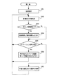
次に、図2のフローチャートを参照して、監視制御部11の動作を説明する。 Next, the operation of the monitoring control unit 11 will be described with reference to the flowchart of FIG.
監視制御部11は、まず、組電池12に対する初期設定を行う(ステップS201)。図3は、蓄電池121,122,123,124の正常/異常(劣化)(○:正常、×:異常(劣化))、および、バイパス部131,132,133,134の状態を示す説明図である。
The monitoring control unit 11 first makes initial settings for the assembled battery 12 (step S201). FIG. 3 is an explanatory diagram showing the normal / abnormal (deteriorated) (○: normal, ×: abnormal (deteriorated)) of the
監視制御部11は、初期設定において、バイパス部131,132,133,134の状態を、図3における「通常」の欄に示される状態に設定する。すなわち、スイッチ144においてのみ、共通端子とオン端子とが接続される(バイパス部134のみがオン状態になる。)ように制御する。その結果、稼働する蓄電池群が蓄電池121,122,123で構成され、蓄電池124が予備の蓄電池に位置づけられる。
In the initial setting, the monitoring control unit 11 sets the state of the
監視制御部11は、蓄電池121,122,123の監視(状態確認)を行う(ステップS202)。
The monitoring control unit 11 monitors (checks the status) of the
なお、ステップS202の監視処理は、蓄電池121,122,123が劣化しているか否か監視する処理である。劣化しているか否かの判定方法として、知られているいずれの方法を用いてもよい。例えば、監視制御部11は、単体の出力電圧があらかじめ決められているしきい値未満になっている場合に、劣化していると判定する。また、監視制御部11は、蓄電池の温度が規定値以上になったら劣化していると判定したり、蓄電池の内部抵抗値が規定値以上になったら劣化している(鉛蓄電池の場合)と判定したりしてもよい。
The monitoring process in step S202 is a process for monitoring whether or not the
ステップS202の監視処理の結果、劣化した蓄電池が検出された場合には(ステップS203)、監視制御部11は、その蓄電池と予備の蓄電池124とを交代させる(ステップS204) When a deteriorated storage battery is detected as a result of the monitoring process in step S202 (step S203), the monitoring control unit 11 replaces the storage battery with the spare storage battery 124 (step S204).
例えば、蓄電池121の劣化が検出されたときには、監視制御部11は、図3における「蓄電池121劣化」の行に示すように、「通常」の場合の状態から、スイッチ144の共通端子とオフ端子とが接続されるように変更する(バイパス部134を「オフ状態」にする。)とともに、スイッチ141の共通端子とオン端子とが接続されるように変更する(バイパス部131を「オン状態」にする。)。
For example, when the deterioration of the
また、監視制御部11は、稼働する蓄電池群を構成する蓄電池のローテーションを行う。 Further, the monitoring control unit 11 rotates the storage batteries constituting the operating storage battery group.
すなわち、監視制御部11は、ローテーション条件(交代条件)が成立したら、稼働する蓄電池群を構成する蓄電池のうちの1つの蓄電池を蓄電池群から切り離し、そのときに予備とされている蓄電池を、蓄電池群に追加する。蓄電池の交代(切り離しと追加)は、バイパス部が「オン状態」から「オフ状態」に変化したり「オフ状態」から「オン状態」に変化したりするように、スイッチ141,142,144,144が監視制御部11によって制御されることによって実現される。 That is, when the rotation condition (replacement condition) is satisfied, the monitoring control unit 11 disconnects one of the storage batteries constituting the operating storage battery group from the storage battery group, and replaces the storage battery reserved at that time with the storage battery. Add to the group. Battery replacement (disconnection and addition) switches 141, 142, 144, so that the bypass section changes from "on state" to "off state" or from "off state" to "on state". It is realized by controlling 144 by the monitoring control unit 11.
図4は、蓄電池のローテーション(交代)を説明するための説明図である。図4において、「○」は稼働する蓄電池群を構成することを示し、「×」は蓄電池群から切り離されることを示す。図4には、対応するバイパス部131,132,133,134の状態も示されている。本実施形態では、例えば、図4における第1行に示す状態から第4行に示す状態に順に遷移する。よって、蓄電池121,122,123,124は、順に、予備の蓄電池とされる。
FIG. 4 is an explanatory diagram for explaining the rotation (replacement) of the storage battery. In FIG. 4, “◯” indicates that it constitutes an operating storage battery group, and “x” indicates that it is separated from the storage battery group. FIG. 4 also shows the states of the
なお、ローテーション条件は、例えば、24時間経過、1週間経過、1か月経過などであるが、他の条件を用いてもよい。また、組電池12が新規に稼働してからの経過時間に応じて、ローテーション条件を変更してもよい(例えば、経過時間が長くなると、1か月から1週間に変更するなど)。
The rotation conditions are, for example, 24 hours, 1 week, 1 month, and the like, but other conditions may be used. Further, the rotation condition may be changed according to the elapsed time since the assembled
また、監視制御部11は、予備とされている蓄電池の充電率を制御する(ステップS207)。例えば、監視制御部11は、リレー14を駆動して充放電装置13を蓄電池に接続し、充電率が所定値(例えば、100%)になるように蓄電池をトリクル充電させる。また、監視制御部11は、充足率の上限しきい値および下限しきい値をあらかじめ決めておき、蓄電池の充電率がしきい値の範囲を越えたら、監視制御部11は、リレー14を駆動するとともに充放電装置13を制御して、しきい値の範囲に収まるように蓄電池を充放電するようにしてもよい。その場合、しきい値の範囲は、一例として、80〜100%であるが、蓄電池のタイプに応じて蓄電池が劣化しにくい範囲が選定されることが好ましい。
Further, the monitoring control unit 11 controls the charge rate of the spare storage battery (step S207). For example, the monitoring control unit 11 drives the
以上に説明したように、本実施形態では、ローテーションによって稼働する蓄電池と予備の蓄電池とを、例えば定期的に入れ替えるので、組電池を構成する全ての蓄電池の使用状況が均等になる。その結果、組電池全体としての寿命が延長される。すなわち、組電池の交換の頻度を下げることができ、組電池を用いた無停電電源装置などの保守費用等が低減する。 As described above, in the present embodiment, since the storage battery that operates by rotation and the spare storage battery are replaced, for example, periodically, the usage status of all the storage batteries constituting the assembled battery becomes equal. As a result, the life of the assembled battery as a whole is extended. That is, the frequency of replacement of the assembled battery can be reduced, and the maintenance cost of the uninterruptible power supply using the assembled battery can be reduced.
実施形態2.
第1の実施形態では、組電池を構成する蓄電池121,122,123,124が、均等に扱われてローテーションがなされる。しかし、各々の特電池の劣化を考慮して蓄電池121,122,123,124をローテーションさせるようにしてもよい。
In the first embodiment, the
図5は、そのような制御を行う第2の実施形態における監視制御部11の動作を示すフローチャートである。 FIG. 5 is a flowchart showing the operation of the monitoring control unit 11 in the second embodiment of performing such control.
第2の実施形態では、監視制御部11は、ローテーション条件が成立したときに(ステップS205)、各蓄電池121,122,123,124の劣化を考慮して、蓄電池の交代(稼働する蓄電池群からの切り離しと蓄電池群への追加)を決定する(ステップS216)。
In the second embodiment, when the rotation condition is satisfied (step S205), the monitoring control unit 11 replaces the storage batteries (from the operating storage battery group) in consideration of the deterioration of the
監視制御部11は、ステップS202の処理で、劣化している蓄電池を特定できる。そこで、そのような蓄電池が次々回の蓄電池群からの切り離し対象になっている場合には、次回の交代時にその蓄電池を蓄電池群から切り離す。すなわち、早めに、予備の蓄電池としての地位に移行させる。 The monitoring control unit 11 can identify the deteriorated storage battery in the process of step S202. Therefore, when such a storage battery is to be separated from the storage battery group one after another, the storage battery is separated from the storage battery group at the next replacement. That is, it will shift to the position as a spare storage battery as soon as possible.
なお、監視制御部11は、次に蓄電池群からの切り離し対象になっている蓄電池が劣化しているものである場合に、通常より早めに蓄電池の交代を行うようにしてもよい(ローテーション条件が期間である場合)。 The monitoring control unit 11 may replace the storage battery earlier than usual when the storage battery to be separated from the storage battery group is deteriorated (rotation condition is set). If it is a period).
なお、上記のような制御が実行されることによって、劣化していると判定された蓄電池が予備の蓄電池になっている期間は、劣化していないと判定された蓄電池が予備の蓄電池になっている期間よりも長くなる。 By executing the above control, the storage battery determined to be deteriorated becomes a spare storage battery during the period in which the storage battery determined to be deteriorated becomes a spare storage battery. It will be longer than the period you are in.
また、監視制御部11は、劣化の度合いにランクを付け、ランクに応じて蓄電池の交代を決定するようにしてもよい。例えば、各蓄電池121,122,123,124の劣化の度合いを知るために、監視制御部11は、ステップS202の処理で、劣化のランク付けも行う。一例として、劣化の判定の具体的対象である観測対象(出力電圧や、温度または内部抵抗値など)について、複数の異なる基準値(出力電圧の低下、温度または内部抵抗値の上昇に対する複数の異なる値)を設け、監視制御部11は、実際に検知された値と基準値とを比較することによって劣化のランク付けを行う。
Further, the monitoring control unit 11 may rank the degree of deterioration and determine the replacement of the storage battery according to the rank. For example, in order to know the degree of deterioration of each
そして、例えばローテーション条件が期間である場合、次に蓄電池群からの切り離し対象になっている蓄電池が、劣化の度合いが高い蓄電池であったときには、早めに蓄電池の交代を行う。 Then, for example, when the rotation condition is a period and the storage battery to be separated from the storage battery group is a storage battery having a high degree of deterioration, the storage battery is replaced as soon as possible.
以上のような制御が行われることによって、劣化している蓄電池が実際に稼働する蓄電池(予備ではない蓄電池)になる機会が減り、組電池全体としてのさらなる寿命延長を期待できる。 By performing the above control, the chance that the deteriorated storage battery becomes an actually operating storage battery (non-spare storage battery) is reduced, and further extension of the life of the assembled battery as a whole can be expected.
なお、上記の各実施形態では、組電池と監視制御部11とが別個に設けられているが、図1に示された組電池と監視制御部11とを含むものを、1つの組電池と定義してもよい。 In each of the above embodiments, the assembled battery and the monitoring control unit 11 are separately provided, but the battery including the assembled battery and the monitoring control unit 11 shown in FIG. 1 is combined with one assembled battery. It may be defined.
また、上記の各実施形態の組電池は、無停電電源装置に好適に組み込まれる。しかし、上記の各実施形態の組電池を無停電電源装置以外に組み込むこともできる。 Further, the assembled battery of each of the above embodiments is suitably incorporated in the uninterruptible power supply device. However, the assembled battery of each of the above embodiments can be incorporated in other than the uninterruptible power supply.
1 組電池システム
11 監視制御部
12 組電池
13 充放電装置
14 リレー
121,122,123,124 蓄電池
131,132,133,134 バイパス部
141,142,143,144 スイッチ
1 set battery system 11
Claims (9)
所望の電圧を出力するために稼働している蓄電池とそれ以外の蓄電池とを交代させることによって、全ての蓄電池に、予備としての蓄電池になる機会を与え、
蓄電池が劣化しているか否か判定し、
劣化していると判定された蓄電池の予備としての蓄電池になっている期間を、劣化していないと判定された蓄電池の当該期間よりも長くする
ことを特徴とする組電池の制御方法。 It is a control method of an assembled battery in which a larger number of storage batteries than the number for outputting a desired voltage are arranged in series.
By replacing the operating storage battery with the other storage batteries to output the desired voltage, all storage batteries are given the opportunity to become spare storage batteries.
Determine if the storage battery is deteriorated and
A method for controlling an assembled battery, which comprises making the period of a storage battery as a spare of a storage battery determined to be deteriorated longer than the period of the storage battery determined to be not deteriorated.
請求項1記載の組電池の制御方法。 The method for controlling an assembled battery according to claim 1, wherein a storage battery that is operating to output a desired voltage is periodically replaced with another storage battery.
請求項2記載の組電池の制御方法。The method for controlling an assembled battery according to claim 2.
請求項1から請求項3のうちのいずれか1項に記載の組電池の制御方法。 The method for controlling an assembled battery according to any one of claims 1 to 3, wherein trickle charge is performed so that the charge rate of the spare storage battery becomes a predetermined value.
前記監視制御部は、所望の電圧を出力するために稼働している蓄電池とそれ以外の蓄電池とを交代させることによって、全ての蓄電池に、予備としての蓄電池になる機会を与え、
前記監視制御部は、蓄電池が劣化しているか否か判定する手段を含み、劣化していると判定された蓄電池の予備としての蓄電池になっている期間を、劣化していないと判定された蓄電池の当該期間よりも長くする
ことを特徴とする組電池システム。 An assembled battery system including an assembled battery in which a larger number of storage batteries than the number for outputting a desired voltage are arranged in series, and a monitoring control unit for monitoring and controlling the assembled battery.
The monitoring control unit gives all the storage batteries an opportunity to become a spare storage battery by replacing the operating storage battery with the other storage batteries to output the desired voltage .
The monitoring control unit includes a means for determining whether or not the storage battery is deteriorated, and the storage battery determined not to be deteriorated during the period of being a spare storage battery for the storage battery determined to be deteriorated. An assembled battery system characterized in that it is longer than the relevant period.
請求項5記載の組電池システム。 The assembled battery system according to claim 5, wherein the monitoring and control unit periodically controls to switch between a storage battery that is operating to output a desired voltage and a storage battery other than the storage battery.
請求項6記載の組電池システム。The assembled battery system according to claim 6.
請求項5から請求項7のうちのいずれか1項に記載の組電池システム。 The assembled battery system according to any one of claims 5 to 7, wherein the monitoring control unit controls trickle charging so that the charging rate of the spare storage battery becomes a predetermined value.
Priority Applications (1)
| Application Number | Priority Date | Filing Date | Title |
|---|---|---|---|
| JP2017068141A JP6904005B2 (en) | 2017-03-30 | 2017-03-30 | Battery control method, battery system and uninterruptible power supply |
Applications Claiming Priority (1)
| Application Number | Priority Date | Filing Date | Title |
|---|---|---|---|
| JP2017068141A JP6904005B2 (en) | 2017-03-30 | 2017-03-30 | Battery control method, battery system and uninterruptible power supply |
Publications (2)
| Publication Number | Publication Date |
|---|---|
| JP2018170911A JP2018170911A (en) | 2018-11-01 |
| JP6904005B2 true JP6904005B2 (en) | 2021-07-14 |
Family
ID=64020654
Family Applications (1)
| Application Number | Title | Priority Date | Filing Date |
|---|---|---|---|
| JP2017068141A Active JP6904005B2 (en) | 2017-03-30 | 2017-03-30 | Battery control method, battery system and uninterruptible power supply |
Country Status (1)
| Country | Link |
|---|---|
| JP (1) | JP6904005B2 (en) |
Family Cites Families (11)
| Publication number | Priority date | Publication date | Assignee | Title |
|---|---|---|---|---|
| JP3114673B2 (en) * | 1997-11-07 | 2000-12-04 | 日本電気株式会社 | Uninterruptible power supply with redundant function |
| US6084382A (en) * | 1998-04-27 | 2000-07-04 | Hewlett-Packard Company | Battery systems and methods of supplying electrical energy |
| JP2001333542A (en) * | 2000-05-19 | 2001-11-30 | Fuji Electric Co Ltd | Charging device |
| US7491457B2 (en) * | 2002-08-16 | 2009-02-17 | Hewlett-Packard Development Company, L.P. | Fuel cell apparatus |
| JP4633615B2 (en) * | 2005-12-12 | 2011-02-16 | 株式会社Nttファシリティーズ | Battery pack and method of charging the battery pack |
| JP2009213248A (en) * | 2008-03-04 | 2009-09-17 | Nec Corp | Battery device and control method therefor |
| US8330420B2 (en) * | 2009-04-10 | 2012-12-11 | The Regents Of The University Of Michigan | Dynamically reconfigurable framework for a large-scale battery system |
| US9246337B2 (en) * | 2010-04-23 | 2016-01-26 | Hitachi, Ltd. | Battery pack and battery pack controller |
| JP2011257314A (en) * | 2010-06-10 | 2011-12-22 | Toyota Motor Corp | Method for determining deterioration of secondary battery and control system for secondary battery |
| JP2012125122A (en) * | 2010-12-10 | 2012-06-28 | Nippon Telegr & Teleph Corp <Ntt> | Power system |
| CN104157918A (en) * | 2014-07-31 | 2014-11-19 | 广州市明昕通信技术有限公司 | Method and device for performing redundant reassembling on storage batteries |
-
2017
- 2017-03-30 JP JP2017068141A patent/JP6904005B2/en active Active
Also Published As
| Publication number | Publication date |
|---|---|
| JP2018170911A (en) | 2018-11-01 |
Similar Documents
| Publication | Publication Date | Title |
|---|---|---|
| JP5319081B2 (en) | Manufacturing method of battery pack with controller | |
| JP5461482B2 (en) | Battery system | |
| JP4935893B2 (en) | Battery abnormality determination device | |
| US8680814B2 (en) | Battery charger and battery charging method | |
| JP5366194B2 (en) | Secondary battery pack | |
| JP5338701B2 (en) | Battery monitoring device | |
| JP6477593B2 (en) | Battery pack monitoring system | |
| JP2009016162A (en) | Battery pack and its manufacturing method | |
| JP5910889B2 (en) | Power storage system | |
| EP3128639B1 (en) | Electricity storage element charging method and electricity storage device | |
| JP4855871B2 (en) | Charger | |
| JP2013207844A (en) | Battery management device, battery device, disk array device, and battery management method | |
| US9537327B2 (en) | Battery cell balancing control system and battery management method thereof | |
| US20120306448A1 (en) | Charge balancing topology | |
| EP2579383A1 (en) | Battery pack for electric power tool | |
| CN105527582A (en) | Method for pre-judging fault battery in power battery pack | |
| JP2008099492A (en) | Battery unit control method and battery unit controller | |
| JP3709766B2 (en) | Battery capacity adjustment method | |
| JP6904005B2 (en) | Battery control method, battery system and uninterruptible power supply | |
| JP3770212B2 (en) | Battery device control method | |
| JP5332062B2 (en) | Uninterruptible power supply system and battery charging method | |
| JP2018074862A (en) | Power supply device and discharge/charge control method | |
| US20140091768A1 (en) | Storage device for storing electrical energy and method for operating a storage device | |
| TWI415363B (en) | Battery management circuit, battery module and battery management method | |
| JP2011010448A (en) | Control unit |
Legal Events
| Date | Code | Title | Description |
|---|---|---|---|
| A621 | Written request for application examination |
Free format text: JAPANESE INTERMEDIATE CODE: A621 Effective date: 20200206 |
|
| A977 | Report on retrieval |
Free format text: JAPANESE INTERMEDIATE CODE: A971007 Effective date: 20201030 |
|
| A131 | Notification of reasons for refusal |
Free format text: JAPANESE INTERMEDIATE CODE: A131 Effective date: 20201124 |
|
| A521 | Written amendment |
Free format text: JAPANESE INTERMEDIATE CODE: A523 Effective date: 20201223 |
|
| TRDD | Decision of grant or rejection written | ||
| A01 | Written decision to grant a patent or to grant a registration (utility model) |
Free format text: JAPANESE INTERMEDIATE CODE: A01 Effective date: 20210525 |
|
| A61 | First payment of annual fees (during grant procedure) |
Free format text: JAPANESE INTERMEDIATE CODE: A61 Effective date: 20210607 |
|
| R150 | Certificate of patent or registration of utility model |
Ref document number: 6904005 Country of ref document: JP Free format text: JAPANESE INTERMEDIATE CODE: R150 |