JP6900817B2 - Head cleaning mechanism and inkjet recording device equipped with it - Google Patents

Head cleaning mechanism and inkjet recording device equipped with it Download PDF

Info

Publication number
JP6900817B2
JP6900817B2 JP2017145320A JP2017145320A JP6900817B2 JP 6900817 B2 JP6900817 B2 JP 6900817B2 JP 2017145320 A JP2017145320 A JP 2017145320A JP 2017145320 A JP2017145320 A JP 2017145320A JP 6900817 B2 JP6900817 B2 JP 6900817B2
Authority
JP
Japan
Prior art keywords
cleaning liquid
ink ejection
liquid supply
wiper
head
Prior art date
Legal status (The legal status is an assumption and is not a legal conclusion. Google has not performed a legal analysis and makes no representation as to the accuracy of the status listed.)
Active
Application number
JP2017145320A
Other languages
Japanese (ja)
Other versions
JP2019025709A5 (en
JP2019025709A (en
Inventor
徳昭 古川
徳昭 古川
隆志 染手
隆志 染手
前嶌 正展
正展 前嶌
Current Assignee (The listed assignees may be inaccurate. Google has not performed a legal analysis and makes no representation or warranty as to the accuracy of the list.)
Kyocera Document Solutions Inc
Original Assignee
Kyocera Document Solutions Inc
Priority date (The priority date is an assumption and is not a legal conclusion. Google has not performed a legal analysis and makes no representation as to the accuracy of the date listed.)
Filing date
Publication date
Application filed by Kyocera Document Solutions Inc filed Critical Kyocera Document Solutions Inc
Priority to JP2017145320A priority Critical patent/JP6900817B2/en
Publication of JP2019025709A publication Critical patent/JP2019025709A/en
Publication of JP2019025709A5 publication Critical patent/JP2019025709A5/ja
Application granted granted Critical
Publication of JP6900817B2 publication Critical patent/JP6900817B2/en
Active legal-status Critical Current
Anticipated expiration legal-status Critical

Links

Images

Landscapes

  • Ink Jet (AREA)

Description

本発明は、用紙のような記録媒体にインクを吐出するインク吐出口を有する記録ヘッドを含むヘッドクリーニング機構及びそれを備えたインクジェット記録装置に関するものである。 The present invention relates to a head cleaning mechanism including a recording head having an ink ejection port for ejecting ink to a recording medium such as paper, and an inkjet recording apparatus including the head cleaning mechanism.

ファクシミリ、複写機、プリンターのような記録装置として、インクを吐出して画像を形成するインクジェット記録装置が、高精細な画像を形成できることから広く用いられている。 As a recording device such as a facsimile, a copier, and a printer, an inkjet recording device that ejects ink to form an image is widely used because it can form a high-definition image.

このようなインクジェット記録装置では、画像記録のためのインク滴と共に吐出される微小なインク滴(以下、ミストと称する)や、インク滴が記録媒体に付着した際に発生する跳ね返りミストが、記録ヘッドのインク吐出面に付着して固化する。インク吐出面のミストが徐々に増加しインク吐出口に重なると、インクの直進性の悪化(飛翔曲がり)や不吐出等が発生して記録ヘッドの印字性能が低下する。 In such an inkjet recording device, minute ink droplets (hereinafter referred to as mist) ejected together with ink droplets for image recording and rebound mist generated when the ink droplets adhere to a recording medium are recorded heads. Adheres to the ink ejection surface and solidifies. When the mist on the ink ejection surface gradually increases and overlaps with the ink ejection port, the straightness of the ink deteriorates (flying bend), non-ejection occurs, and the printing performance of the recording head deteriorates.

そこで、記録ヘッドのインク吐出面を清浄化するために、インク吐出面のうちの複数のインク吐出口が開口するインク吐出領域の外側(ワイパーのワイピング方向上流側)の部分に、クリーニング液供給口を複数個設けたインクジェット記録装置が知られている。このインクジェット記録装置では、クリーニング液供給口からクリーニング液を供給した後、ワイパーをクリーニング液供給口よりも外側からインク吐出面に沿って移動させることによって、ワイパーでクリーニング液を保持しながらインク吐出面を拭くことができる。このようにして、記録ヘッドの回復処理を行うことができる。 Therefore, in order to clean the ink ejection surface of the recording head, a cleaning liquid supply port is provided on the outside of the ink ejection region (upstream in the wiping direction of the wiper) where a plurality of ink ejection ports are opened. There is known an inkjet recording device provided with a plurality of the above. In this inkjet recording device, after the cleaning liquid is supplied from the cleaning liquid supply port, the wiper is moved along the ink ejection surface from the outside of the cleaning liquid supply port, so that the ink ejection surface is held by the wiper while holding the cleaning liquid. Can be wiped. In this way, the recovery process of the recording head can be performed.

なお、記録ヘッドのインク吐出面にクリーニング液供給口を複数個設けたインクジェット記録装置は、例えば特許文献1に開示されている。 An inkjet recording apparatus provided with a plurality of cleaning liquid supply ports on the ink ejection surface of the recording head is disclosed in, for example, Patent Document 1.

特開2007−83496号公報Japanese Unexamined Patent Publication No. 2007-83496

しかしながら、上記従来のインクジェット記録装置では、記録ヘッドの回復処理を行う度にワイパーがクリーニング液供給口上を通過するため、クリーニング液供給口の縁部によってワイパーの先端に傷が生じるという問題点がある。なお、ワイパーの先端の傷が大きくなりワイパーの先端に欠けが生じると、ワイパーの拭き取り性能は著しく低下し、拭き残しが生じる。 However, in the above-mentioned conventional inkjet recording apparatus, since the wiper passes over the cleaning liquid supply port every time the recording head is recovered, there is a problem that the tip of the wiper is scratched by the edge of the cleaning liquid supply port. .. If the tip of the wiper is severely scratched and the tip of the wiper is chipped, the wiping performance of the wiper is significantly reduced and unwiped residue is generated.

本発明は、上記のような課題を解決するためになされたものであり、本発明の目的は、ワイパーが損傷するのを抑制しながら、インク吐出面を清浄化することが可能なヘッドクリーニング機構及びそれを備えたインクジェット記録装置を提供することである。 The present invention has been made to solve the above problems, and an object of the present invention is a head cleaning mechanism capable of cleaning the ink ejection surface while suppressing damage to the wiper. And to provide an inkjet recording apparatus equipped with the same.

上記目的を達成するために、本発明の第1の局面のヘッドクリーニング機構は、記録媒体上にインクを吐出する複数のインク吐出口が開口するインク吐出面を含む記録ヘッドと、インク吐出面を所定方向に拭くワイパーと、を備える。記録ヘッドは、インク吐出面に対してインク吐出面をワイパーが拭く方向であるワイピング方向の上流側に配置され、クリーニング液を供給するクリーニング液供給口が開口するクリーニング液供給面を含む。クリーニング液供給面は、インク吐出面に対するワイパーのオーバーラップ量以下の高さだけインク吐出面よりも高い位置に配置されている。クリーニング液供給面とインク吐出面との境界部分には、ワイピング方向の下流側に向かって下方に傾斜する傾斜面を有する段差部が設けられている。 In order to achieve the above object, the head cleaning mechanism according to the first aspect of the present invention comprises a recording head including an ink ejection surface in which a plurality of ink ejection ports for ejecting ink on a recording medium are opened, and an ink ejection surface. A wiper that wipes in a predetermined direction is provided. Recording head is arranged to discharge surface on the upstream side of the wiping direction in which wiping wiper with respect to the ink ejection surface, torque leaning liquid supply port to supply the cleaning liquid contains a cleaning liquid supply side that is open. The cleaning liquid supply surface is arranged at a position higher than the ink ejection surface by a height equal to or less than the overlap amount of the wiper with respect to the ink ejection surface. At the boundary between the cleaning liquid supply surface and the ink ejection surface, a step portion having an inclined surface that inclines downward toward the downstream side in the wiping direction is provided.

本発明の第1の局面のヘッドクリーニング機構によれば、記録ヘッドは、インク吐出面に対してインク吐出面をワイパーが拭く方向であるワイピング方向の上流側に配置され、クリーニング液を供給するクリーニング液供給口が開口するクリーニング液供給面を含む。これにより、クリーニング液供給口からクリーニング液を供給した後、ワイパーをクリーニング液供給口よりもワイピング方向上流側からインク吐出面に沿って移動させることによって、ワイパーでクリーニング液を保持しながらインク吐出面を拭くことができる。このため、インク吐出面を清浄化することができる。 According to a first aspect of the head cleaning mechanism of the present invention, the recording head is disposed an ink ejection surface on the upstream side of the wiping direction in which wiping wiper with respect to the ink discharge surface, that to supply cleaning fluid cleaning liquid supply port comprises a cleaning fluid supply side to be opened. As a result, after the cleaning liquid is supplied from the cleaning liquid supply port, the wiper is moved along the ink ejection surface from the upstream side in the wiping direction from the cleaning liquid supply port, so that the ink ejection surface is held by the wiper while holding the cleaning liquid. Can be wiped. Therefore, the ink ejection surface can be cleaned.

また、クリーニング液供給面は、インク吐出面よりも高い位置に配置されている。これにより、クリーニング液供給面に対するワイパーの圧接力を抑制することができるので、ワイパーの先端がクリーニング液供給口の縁部により損傷するのを抑制することができる。なお、クリーニング液供給面は、インク吐出面に対するワイパーのオーバーラップ量以下の高さだけインク吐出面よりも高い位置に配置されているので、ワイパーがクリーニング液供給面に接触せずにクリーニング液がクリーニング液供給面に残るのを抑制することができる。 Further, the cleaning liquid supply surface is arranged at a position higher than the ink ejection surface. As a result, the pressure contact force of the wiper with respect to the cleaning liquid supply surface can be suppressed, so that the tip of the wiper can be prevented from being damaged by the edge of the cleaning liquid supply port. Since the cleaning liquid supply surface is arranged at a position higher than the ink discharge surface by a height equal to or less than the overlap amount of the wiper with respect to the ink discharge surface, the cleaning liquid does not come into contact with the cleaning liquid supply surface. It can be suppressed from remaining on the cleaning liquid supply surface.

また、クリーニング液供給面とインク吐出面との境界部分には、ワイピング方向の下流側に向かって下方に傾斜する傾斜面を有する段差部が設けられている。これにより、ワイパーがクリーニング液供給面からインク吐出面に移動する際に、クリーニング液供給面とインク吐出面との境界部分にクリーニング液が残るのを抑制することができる。 Further, at the boundary portion between the cleaning liquid supply surface and the ink ejection surface, a step portion having an inclined surface that inclines downward toward the downstream side in the wiping direction is provided. As a result, when the wiper moves from the cleaning liquid supply surface to the ink discharge surface, it is possible to prevent the cleaning liquid from remaining at the boundary portion between the cleaning liquid supply surface and the ink discharge surface.

本発明の一実施形態のヘッドクリーニング機構を備えたインクジェット記録装置の構造を示す図The figure which shows the structure of the inkjet recording apparatus provided with the head cleaning mechanism of one Embodiment of this invention. 図1に示すインクジェット記録装置の第1搬送ユニット及び記録部を上方から見た図A view of the first transport unit and the recording unit of the inkjet recording apparatus shown in FIG. 1 as viewed from above. 記録部のラインヘッドを構成する記録ヘッドの図Diagram of the recording head that constitutes the line head of the recording unit 記録ヘッドをインク吐出面側から見た図View of the recording head from the ink ejection surface side 記録ヘッドのクリーニング液供給部材のクリーニング液供給口を下方から見た図A view of the cleaning liquid supply port of the cleaning liquid supply member of the recording head as viewed from below. 記録ヘッド、サブタンクおよびメインタンク周辺の構成を示す図The figure which shows the structure around a recording head, a sub tank and a main tank 記録ヘッドのクリーニング液供給面とインク吐出面との境界部分の構造を示す図The figure which shows the structure of the boundary part between the cleaning liquid supply surface and the ink discharge surface of a recording head. ワイパーがインク吐出面に圧接された状態で矢印A方向に移動している状態を示す図The figure which shows the state which the wiper is moving in the direction of arrow A while being pressure-contacted with the ink ejection surface. ワイパーがクリーニング液供給部材の傾斜面に圧接された状態で矢印A方向に移動している状態を示す図The figure which shows the state which the wiper is moving in the direction of arrow A in the state which is pressed against the inclined surface of a cleaning liquid supply member. メンテナンスユニットを記録部の下方に配置した状態を示す図The figure which shows the state which the maintenance unit is arranged under the recording part. ワイパーを記録ヘッドの下方に配置した状態を示す図The figure which shows the state which the wiper is arranged under the recording head 図11の状態からワイパーを上昇させクリーニング液供給部材に圧接させた状態を示す図The figure which shows the state which raised the wiper from the state of FIG. 11 and brought it into pressure contact with a cleaning liquid supply member. 図12の状態からワイパーをクリーニング液供給部材に圧接させた状態で矢印A方向に移動させた状態を示す図The figure which shows the state which moved in the direction of arrow A with the wiper being pressure-contacted with the cleaning liquid supply member from the state of FIG. 図13の状態からワイパーをさらに矢印A方向に移動させた状態を示す図The figure which shows the state which moved the wiper further in the direction of arrow A from the state of FIG. 図14の状態からワイパーをさらに矢印A方向に移動させた後、ワイパーを下降させインク吐出面から離間させた状態を示す図FIG. 6 shows a state in which the wiper is further moved in the direction of arrow A from the state of FIG. 14, and then the wiper is lowered and separated from the ink ejection surface.

以下、本発明の実施形態について図面を参照して説明する。 Hereinafter, embodiments of the present invention will be described with reference to the drawings.

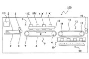
図1に示すように、本発明の一実施形態のインクジェット記録装置100の左側部には用紙S(記録媒体)を収容する給紙トレイ2が設けられており、この給紙トレイ2の一端部には収容された用紙Sを、最上位の用紙Sから順に一枚ずつ後述する第1搬送ユニット5へと搬送給紙するための給紙ローラー3と、給紙ローラー3に圧接され従動回転する従動ローラー4とが設けられている。 As shown in FIG. 1, a paper feed tray 2 for accommodating paper S (recording medium) is provided on the left side of the inkjet recording apparatus 100 according to the embodiment of the present invention, and one end of the paper feed tray 2 is provided. The paper S stored in the paper S is transferred and fed one by one to the first transport unit 5 described later in order from the topmost paper S, and the paper S is pressed against the paper feed roller 3 and driven to rotate. A driven roller 4 is provided.

用紙搬送方向(矢印X方向)に対し給紙ローラー3及び従動ローラー4の下流側(図1の右側)には、第1搬送ユニット5及び記録部9が配置されている。第1搬送ユニット5は、第1駆動ローラー6と、第1従動ローラー7と、第1駆動ローラー6及び第1従動ローラー7に掛け渡された第1搬送ベルト8とを含む構成であり、インクジェット記録装置100の制御部110からの制御信号により第1駆動ローラー6が時計回り方向に回転駆動されることにより、第1搬送ベルト8に保持された用紙Sが矢印X方向に搬送される。 The first transport unit 5 and the recording unit 9 are arranged on the downstream side (right side of FIG. 1) of the paper feed roller 3 and the driven roller 4 with respect to the paper transport direction (arrow X direction). The first transport unit 5 has a configuration including a first drive roller 6, a first driven roller 7, and a first transport belt 8 bridged to the first drive roller 6 and the first driven roller 7, and is an inkjet. The first drive roller 6 is rotationally driven in the clockwise direction by a control signal from the control unit 110 of the recording device 100, so that the paper S held by the first transfer belt 8 is conveyed in the direction of the arrow X.

記録部9は、ヘッドハウジング10と、ヘッドハウジング10に保持されたラインヘッド11C、11M、11Y、及び11Kを備えている。これらのラインヘッド11C〜11Kは、第1搬送ベルト8の搬送面に対して所定の間隔(例えば1mm)が形成されるような高さに支持され、図2に示すように、用紙搬送方向と直交する用紙幅方向(図2の上下方向)に沿って延びる1個以上(ここでは1個)の記録ヘッド17によって構成されている。 The recording unit 9 includes a head housing 10 and line heads 11C, 11M, 11Y, and 11K held in the head housing 10. These line heads 11C to 11K are supported at a height such that a predetermined interval (for example, 1 mm) is formed with respect to the transport surface of the first transport belt 8, and as shown in FIG. It is composed of one or more (here, one) recording heads extending along the orthogonal paper width direction (vertical direction in FIG. 2).

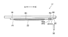
図3及び図4に示すように、記録ヘッド17のヘッド部(インク吐出ヘッド部)18のインク吐出面F1には、インク吐出口18a(図2参照)が多数配列されたインク吐出領域R1が設けられている。 As shown in FIGS. 3 and 4, an ink ejection region R1 in which a large number of ink ejection ports 18a (see FIG. 2) are arranged is provided on the ink ejection surface F1 of the head portion (ink ejection head portion) 18 of the recording head 17. It is provided.

各ラインヘッド11C〜11Kを構成する記録ヘッド17には、それぞれインクタンク(図示せず)に貯留されている4色(シアン、マゼンタ、イエロー及びブラック)のインクがラインヘッド11C〜11Kの色毎に供給される。 In the recording heads 17 constituting the line heads 11C to 11K, four colors (cyan, magenta, yellow, and black) of ink stored in the ink tanks (not shown) are applied to each of the line heads 11C to 11K. Is supplied to.

各記録ヘッド17は、制御部110(図1参照)からの制御信号により外部コンピューターから受信した画像データに応じて、第1搬送ベルト8の搬送面に吸着保持されて搬送される用紙Sに向かってインク吐出口18aからインクを吐出する。これにより、第1搬送ベルト8上の用紙Sにはシアン、マゼンタ、イエロー、ブラックの4色のインクが重ね合わされたカラー画像が形成される。 Each recording head 17 heads toward the paper S which is sucked and held on the transport surface of the first transport belt 8 and transported according to the image data received from the external computer by the control signal from the control unit 110 (see FIG. 1). Ink is ejected from the ink ejection port 18a. As a result, a color image in which four color inks of cyan, magenta, yellow, and black are superimposed is formed on the paper S on the first transport belt 8.

また、記録ヘッド17には、クリーニング液を供給するクリーニング液供給部材(クリーニング液供給ヘッド部)60が設けられている。クリーニング液供給部材60は、ヘッド部18に対して後述するワイパー35のワイピング方向上流側(図3の右側)に隣接して配置されている。クリーニング液供給部材60は、クリーニング液を供給するクリーニング液供給口60a(図5参照)が多数配列されたクリーニング液供給領域R2を含むクリーニング液供給面F2を有する。クリーニング液供給面F2は、インク吐出面F1と平行に配置されている。なお、ヘッド部18の少なくともインク吐出面F1は、例えばSUS(ステンレス鋼)によって形成されており、クリーニング液供給部材60のクリーニング液供給面F2は、例えばSUSまたは樹脂によって形成されている。 Further, the recording head 17 is provided with a cleaning liquid supply member (cleaning liquid supply head portion) 60 for supplying the cleaning liquid. The cleaning liquid supply member 60 is arranged adjacent to the head portion 18 on the upstream side (right side in FIG. 3) of the wiper 35 described later in the wiping direction. The cleaning liquid supply member 60 has a cleaning liquid supply surface F2 including a cleaning liquid supply region R2 in which a large number of cleaning liquid supply ports 60a (see FIG. 5) for supplying the cleaning liquid are arranged. The cleaning liquid supply surface F2 is arranged in parallel with the ink ejection surface F1. At least the ink ejection surface F1 of the head portion 18 is formed of, for example, SUS (stainless steel), and the cleaning liquid supply surface F2 of the cleaning liquid supply member 60 is formed of, for example, SUS or resin.

また、クリーニング液供給部材60のクリーニング液供給面F2に対してワイピング方向上流側(図3の右側)の部分には、上流側傾斜面62が形成されている。 Further, an upstream inclined surface 62 is formed on a portion of the cleaning liquid supply member 60 on the upstream side (right side in FIG. 3) in the wiping direction with respect to the cleaning liquid supply surface F2.

クリーニング液は、インクと類似の成分からなる溶液であることが望ましく、主に水と溶剤成分からなり、必要に応じて界面活性剤、防腐防カビ剤などが添加された液体組成物である。 The cleaning liquid is preferably a solution composed of components similar to ink, and is a liquid composition mainly composed of water and a solvent component, to which a surfactant, an antiseptic and antifungal agent, etc. are added as necessary.

図6に示すように、クリーニング液供給部材60のクリーニング液供給口60a(図5参照)には、クリーニング液23が通過するチューブからなるクリーニング液供給経路70の下流端が接続されている。クリーニング液供給経路70の上流端は、クリーニング液供給部材60に供給するクリーニング液23を収容するサブタンク71に接続されている。クリーニング液供給経路70の上流端は、クリーニング液23に浸かっている。クリーニング液供給経路70には、クリーニング液23をサブタンク71から汲み上げてクリーニング液供給部材60に送る供給ポンプ72が設けられている。なお、図では、理解を容易にするために、クリーニング液23にハッチングを施している。 As shown in FIG. 6, the cleaning liquid supply port 60a (see FIG. 5) of the cleaning liquid supply member 60 is connected to the downstream end of the cleaning liquid supply path 70 including a tube through which the cleaning liquid 23 passes. The upstream end of the cleaning liquid supply path 70 is connected to a sub tank 71 that houses the cleaning liquid 23 supplied to the cleaning liquid supply member 60. The upstream end of the cleaning liquid supply path 70 is immersed in the cleaning liquid 23. The cleaning liquid supply path 70 is provided with a supply pump 72 that pumps the cleaning liquid 23 from the sub tank 71 and sends it to the cleaning liquid supply member 60. In the figure, the cleaning liquid 23 is hatched for easy understanding.

また、サブタンク71には、クリーニング液23が通過するチューブからなるクリーニング液補給経路80の下流端が接続されている。クリーニング液補給経路80の上流端は、サブタンク71に補給するクリーニング液23を収容するメインタンク81に接続されている。クリーニング液補給経路80の上流端は、クリーニング液23に浸かっている。クリーニング液補給経路80には、クリーニング液23をメインタンク81から汲み上げてサブタンク71に送る補給ポンプ82が設けられている。供給ポンプ72および補給ポンプ82としては、例えば、チューブポンプ、シリンジポンプ、ダイアフラムポンプ等を用いることができる。ただし、供給ポンプ72は、供給を停止している時に供給ポンプ72の流入口と流出口との間を遮断した状態と連通した状態とに切り替えることができるように構成されている。なお、クリーニング液供給部材60、サブタンク71およびメインタンク81周辺の詳細構造については、後述する。 Further, the sub tank 71 is connected to the downstream end of the cleaning liquid replenishment path 80, which is composed of a tube through which the cleaning liquid 23 passes. The upstream end of the cleaning liquid replenishment path 80 is connected to the main tank 81 that houses the cleaning liquid 23 to be replenished to the sub tank 71. The upstream end of the cleaning liquid replenishment path 80 is immersed in the cleaning liquid 23. The cleaning liquid replenishment path 80 is provided with a replenishment pump 82 that pumps the cleaning liquid 23 from the main tank 81 and sends it to the sub tank 71. As the supply pump 72 and the supply pump 82, for example, a tube pump, a syringe pump, a diaphragm pump, or the like can be used. However, the supply pump 72 is configured to be able to switch between a state in which the inlet and the outlet of the supply pump 72 are cut off and a state in which the supply pump 72 is in communication with each other when the supply is stopped. The detailed structure around the cleaning liquid supply member 60, the sub tank 71, and the main tank 81 will be described later.

このインクジェット記録装置100では、記録ヘッド17のインク吐出面F1を清浄にするために、長期間停止後の印字開始時及び印字動作の合間には、全ての記録ヘッド17のインク吐出口18aからインクを強制的に排出し、並行して全ての記録ヘッド17のクリーニング液供給口60a(図5参照)からクリーニング液供給領域R2にクリーニング液23を供給し、後述するワイパー35によりインク吐出面F1を拭き取り、次の印字動作に備える。 In the inkjet recording apparatus 100, in order to clean the ink ejection surface F1 of the recording head 17, ink is ink from all the ink ejection ports 18a of the recording head 17 at the start of printing after a long-term stop and between printing operations. Is forcibly discharged, and in parallel, the cleaning liquid 23 is supplied from the cleaning liquid supply port 60a (see FIG. 5) of all the recording heads 17 to the cleaning liquid supply region R2, and the ink ejection surface F1 is pressed by the wiper 35 described later. Wipe off and prepare for the next printing operation.

図1に戻って、用紙搬送方向に対し第1搬送ユニット5の下流側(図1の右側)には第2搬送ユニット12が配置されている。第2搬送ユニット12は、第2駆動ローラー13と、第2従動ローラー14と、第2駆動ローラー13及び第2従動ローラー14に掛け渡された第2搬送ベルト15とを含む構成であり、第2駆動ローラー13が時計回り方向に回転駆動されることにより、第2搬送ベルト15に保持された用紙Sが矢印X方向に搬送される。 Returning to FIG. 1, the second transport unit 12 is arranged on the downstream side (right side of FIG. 1) of the first transport unit 5 with respect to the paper transport direction. The second transport unit 12 has a configuration including a second drive roller 13, a second driven roller 14, and a second transport belt 15 spanned by the second drive roller 13 and the second driven roller 14. By rotationally driving the two-drive roller 13 in the clockwise direction, the paper S held by the second transport belt 15 is conveyed in the direction of the arrow X.

記録部9にてインク画像が記録された用紙Sは第2搬送ユニット12へと送られ、第2搬送ユニット12を通過する間に用紙S表面に吐出されたインクが乾燥される。また、第2搬送ユニット12の下方にはメンテナンスユニット19及びキャップユニット90が配置されている。上述したワイパー35による拭き取り動作を実行する際には、第1搬送ユニット5が下降し、メンテナンスユニット19は、記録部9の下方に移動し、記録ヘッド17のインク吐出口18aから強制排出されたインクおよびクリーニング液供給口60aから供給されたクリーニング液23を拭き取り、拭き取られたインクおよびクリーニング液23を回収する。記録ヘッド17のインク吐出面F1(図3参照)をキャッピングする際には、第1搬送ユニット5が下降し、キャップユニット90は、記録部9の下方に水平移動し、さらに上方に移動して記録ヘッド17の下面に装着される。 The paper S on which the ink image is recorded by the recording unit 9 is sent to the second transport unit 12, and the ink discharged on the surface of the paper S is dried while passing through the second transport unit 12. Further, a maintenance unit 19 and a cap unit 90 are arranged below the second transport unit 12. When the wiping operation by the wiper 35 described above is executed, the first transport unit 5 is lowered, the maintenance unit 19 is moved below the recording unit 9, and is forcibly discharged from the ink ejection port 18a of the recording head 17. The cleaning liquid 23 supplied from the ink and cleaning liquid supply port 60a is wiped off, and the wiped ink and cleaning liquid 23 are collected. When capping the ink ejection surface F1 (see FIG. 3) of the recording head 17, the first transport unit 5 is lowered, and the cap unit 90 is horizontally moved below the recording unit 9 and further moved upward. It is mounted on the lower surface of the recording head 17.

また、用紙搬送方向に対し第2搬送ユニット12の下流側には、画像が記録された用紙Sを装置本体外へと排出する排出ローラー対16が設けられており、排出ローラー対16の下流側には、装置本体外へと排出された用紙Sが積載される排出トレイ(図示せず)が設けられている。 Further, on the downstream side of the second transport unit 12 with respect to the paper transport direction, a discharge roller pair 16 for discharging the paper S on which the image is recorded to the outside of the apparatus main body is provided, and is a downstream side of the discharge roller pair 16. Is provided with a discharge tray (not shown) on which the paper S discharged to the outside of the main body of the apparatus is loaded.

メンテナンスユニット19は、インク吐出面F1に沿って移動可能な複数のワイパー35(図8参照)と、複数のワイパー35が固定された略矩形状のキャリッジ(図示せず)と、キャリッジを支持する支持フレーム(図示せず)とで構成されている。キャリッジ(図示せず)は支持フレーム(図示せず)に対し矢印AA′方向に摺動可能に支持される。 The maintenance unit 19 supports a plurality of wipers 35 (see FIG. 8) that can move along the ink ejection surface F1, a substantially rectangular carriage (not shown) to which the plurality of wipers 35 are fixed, and a carriage. It is composed of a support frame (not shown). The carriage (not shown) is slidably supported in the direction of arrow AA'with respect to the support frame (not shown).

ワイパー35は、各記録ヘッド17のクリーニング液供給口60a(図5参照)から供給されたクリーニング液23を拭き取るための弾性部材(例えばEPDMからなるゴム製の部材)である。ワイパー35は、クリーニング液供給部材60のクリーニング液供給領域R2(図4参照)に対してワイピング方向上流側の部分(ここでは、上流側傾斜面62)に圧接され、キャリッジ(図示せず)の移動によりクリーニング液供給面F2およびインク吐出面F1を所定方向(矢印A方向)に拭く。なお、メンテナンスユニット19および記録ヘッド17によって、ヘッドクリーニング機構が構成されている。 The wiper 35 is an elastic member (for example, a rubber member made of EPDM) for wiping the cleaning liquid 23 supplied from the cleaning liquid supply port 60a (see FIG. 5) of each recording head 17. The wiper 35 is pressed against a portion (here, an inclined surface 62 on the upstream side) in the wiping direction with respect to the cleaning liquid supply region R2 (see FIG. 4) of the cleaning liquid supply member 60, and is of a carriage (not shown). By moving, the cleaning liquid supply surface F2 and the ink ejection surface F1 are wiped in a predetermined direction (arrow A direction). The maintenance unit 19 and the recording head 17 form a head cleaning mechanism.

次に、クリーニング液供給部材60、サブタンク71およびメインタンク81周辺の構造を詳細に説明する。 Next, the structures around the cleaning liquid supply member 60, the sub tank 71, and the main tank 81 will be described in detail.

図6に示すように、サブタンク71には、内部空間の気圧を大気圧と等しくするための大気開放口71aが設けられている。また、サブタンク71の所定位置には、クリーニング液23を検知する第1検知センサー73が設けられている。第1検知センサー73は、電圧が印加されるとともにサブタンク71内に配置される電極対(図示せず)を有する。第1検知センサー73は、電極間の通電の有無に基づいて、クリーニング液23の有無を検知可能である。第1検知センサー73によって液無し(通電無し)が検知されると、液有り(通電有り)が検知されるまで、補給ポンプ82によってメインタンク81からサブタンク71にクリーニング液23が補給される。これにより、サブタンク71内のクリーニング液23の液面(上面)は、略一定の高さに維持される。 As shown in FIG. 6, the sub tank 71 is provided with an atmospheric opening 71a for making the pressure in the internal space equal to the atmospheric pressure. Further, a first detection sensor 73 for detecting the cleaning liquid 23 is provided at a predetermined position of the sub tank 71. The first detection sensor 73 has an electrode pair (not shown) arranged in the sub tank 71 when a voltage is applied. The first detection sensor 73 can detect the presence / absence of the cleaning liquid 23 based on the presence / absence of energization between the electrodes. When the first detection sensor 73 detects that there is no liquid (without energization), the replenishment pump 82 replenishes the cleaning liquid 23 from the main tank 81 to the sub tank 71 until the presence of liquid (with energization) is detected. As a result, the liquid level (upper surface) of the cleaning liquid 23 in the sub tank 71 is maintained at a substantially constant height.

メインタンク81の下部には、クリーニング液23を検知する第2検知センサー83が設けられている。第2検知センサー83は、電圧が印加されるとともにメインタンク81内に配置される電極対(図示せず)を有する。第2検知センサー83は、電極間の通電の有無に基づいて、クリーニング液23の有無を検知可能である。第2検知センサー83によって液無しが検知されると、インクジェット記録装置100の表示パネル(図示せず)にメインタンク81が空になったことが報知される。これにより、ユーザーまたは作業者によって、メインタンク81が新品に交換、又はメインタンク81にクリーニング液23が補充される。 A second detection sensor 83 that detects the cleaning liquid 23 is provided below the main tank 81. The second detection sensor 83 has an electrode pair (not shown) arranged in the main tank 81 when a voltage is applied. The second detection sensor 83 can detect the presence / absence of the cleaning liquid 23 based on the presence / absence of energization between the electrodes. When the second detection sensor 83 detects that there is no liquid, the display panel (not shown) of the inkjet recording device 100 is notified that the main tank 81 is empty. As a result, the main tank 81 is replaced with a new one, or the main tank 81 is replenished with the cleaning liquid 23 by the user or the operator.

図5に示すように、クリーニング液供給口60aは、ヘッド幅方向(矢印BB´方向、ワイピング方向と直交する方向)に沿って例えば1mmピッチで配置されている。なお、図5では、ヘッド幅方向に沿って配置される複数のクリーニング液供給口60aからなる列を1列のみ描いているが、この列はワイピング方向(矢印A方向)に隣接して複数列設けられていてもよい。 As shown in FIG. 5, the cleaning liquid supply port 60a is arranged at a pitch of, for example, 1 mm along the head width direction (direction of arrow BB', direction orthogonal to the wiping direction). In FIG. 5, only one row consisting of a plurality of cleaning liquid supply ports 60a arranged along the head width direction is drawn, but this row is adjacent to the wiping direction (arrow A direction) and is a plurality of rows. It may be provided.

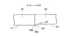
ここで、本実施形態では、図3および図7に示すように、クリーニング液供給面F2は、インク吐出面F1よりも高い位置に配置されている。また、クリーニング液供給面F2は、ワイパー35がインク吐出面F1を拭くときのインク吐出面F1に対するワイパー35の食い込み量(オーバーラップ量)以下の高さだけインク吐出面F1よりも高い位置に配置されている。具体的には、ワイパー35がインク吐出面F1を拭くときのインク吐出面F1に対するワイパー35の食い込み量は、例えば1.0mm以上1.5mm以下に設定されている。クリーニング液供給面F2は、インク吐出面F1よりも例えば0.8mm高い位置に配置されている。なお、クリーニング液供給面F2は、インク吐出面F1よりも約0.2mm以上高い位置に配置されることが好ましい。 Here, in the present embodiment, as shown in FIGS. 3 and 7, the cleaning liquid supply surface F2 is arranged at a position higher than the ink ejection surface F1. Further, the cleaning liquid supply surface F2 is arranged at a position higher than the ink ejection surface F1 by a height equal to or less than the bite amount (overlap amount) of the wiper 35 with respect to the ink ejection surface F1 when the wiper 35 wipes the ink ejection surface F1. Has been done. Specifically, when the wiper 35 wipes the ink ejection surface F1, the amount of the wiper 35 biting into the ink ejection surface F1 is set to, for example, 1.0 mm or more and 1.5 mm or less. The cleaning liquid supply surface F2 is arranged at a position higher than the ink ejection surface F1, for example, by 0.8 mm. The cleaning liquid supply surface F2 is preferably arranged at a position higher than the ink ejection surface F1 by about 0.2 mm or more.

また、クリーニング液供給面F2とインク吐出面F1との境界部分には、ワイピング方向の下流側に向かって下方に傾斜する傾斜面63aを有するとともに、クリーニング液供給面F2よりも下方に突出する段差部63が設けられている。段差部63はクリーニング液供給部材60に一体で設けられており、傾斜面63aはクリーニング液供給面F2に連続して形成されている。 Further, the boundary portion between the cleaning liquid supply surface F2 and the ink ejection surface F1 has an inclined surface 63a that inclines downward toward the downstream side in the wiping direction, and a step protruding downward from the cleaning liquid supply surface F2. A unit 63 is provided. The step portion 63 is integrally provided with the cleaning liquid supply member 60, and the inclined surface 63a is continuously formed on the cleaning liquid supply surface F2.

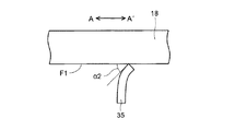
図7および図8に示すように、クリーニング液供給部材60は、傾斜面63aのクリーニング液供給面F2およびインク吐出面F1に対する傾斜角α1(図7参照)が、インク吐出面F1をワイパー35が拭いている状態でのワイパー35の先端部のインク吐出面F1に対する圧接角α2(図8参照)よりも小さくなるように形成されている。具体的には、ワイパー35の先端部のインク吐出面F1に対する圧接角α2は、約45°に設定されている。傾斜面63aのクリーニング液供給面F2およびインク吐出面F1に対する傾斜角α1は、15°以上45°未満に設定されていることが好ましく、30°以上40°未満に設定されていることがより好ましい。 As shown in FIGS. 7 and 8, in the cleaning liquid supply member 60, the inclination angle α1 (see FIG. 7) with respect to the cleaning liquid supply surface F2 and the ink ejection surface F1 of the inclined surface 63a is set on the ink ejection surface F1 by the wiper 35. The tip of the wiper 35 in the wiped state is formed so as to be smaller than the pressure contact angle α2 (see FIG. 8) with respect to the ink ejection surface F1. Specifically, the pressure contact angle α2 of the tip of the wiper 35 with respect to the ink ejection surface F1 is set to about 45 °. The inclination angle α1 with respect to the cleaning liquid supply surface F2 and the ink ejection surface F1 of the inclined surface 63a is preferably set to 15 ° or more and less than 45 °, and more preferably 30 ° or more and less than 40 °. ..

傾斜角α1を圧接角α2よりも小さく形成しているため、図9に示すように、ワイパー35をワイピング方向(図9の左方向)に移動させた際に、ワイパー35の先端のワイピング方向の下流側のコーナー部35aのみが傾斜面63aに接触する。すなわち、ワイパー35のワイピング方向の下流側の側面35bは、傾斜面63aに接触しない。 Since the inclination angle α1 is formed smaller than the pressure contact angle α2, as shown in FIG. 9, when the wiper 35 is moved in the wiping direction (leftward in FIG. 9), the tip of the wiper 35 is in the wiping direction. Only the corner portion 35a on the downstream side comes into contact with the inclined surface 63a. That is, the side surface 35b on the downstream side of the wiper 35 in the wiping direction does not come into contact with the inclined surface 63a.

図7に示すように、傾斜面63aのワイピング方向の下流端63bは、インク吐出面F1と面一、又はインク吐出面F1よりも低い位置に配置されている。傾斜面63aの下流端63bがインク吐出面F1よりも低い位置に配置される場合、傾斜面63aの下流端63bは、クリーニング液供給面F2とインク吐出面F1との段差の1/2(=約0.4mm)以下の高さだけインク吐出面F1よりも低い位置に配置されることが好ましく、ここでは、約0.2mmだけインク吐出面F1よりも低い位置に配置されている。 As shown in FIG. 7, the downstream end 63b of the inclined surface 63a in the wiping direction is arranged flush with the ink ejection surface F1 or at a position lower than the ink ejection surface F1. When the downstream end 63b of the inclined surface 63a is arranged at a position lower than the ink ejection surface F1, the downstream end 63b of the inclined surface 63a is 1/2 (=) of the step between the cleaning liquid supply surface F2 and the ink ejection surface F1. It is preferable that the ink is arranged at a position lower than the ink ejection surface F1 by a height of about 0.4 mm) or less, and here, it is arranged at a position lower than the ink ejection surface F1 by about 0.2 mm.

次に、本実施形態のインクジェット記録装置100における、メンテナンスユニット19を用いた記録ヘッド17の回復動作について説明する。なお、以下で説明する記録ヘッド17の回復動作は、制御部110(図1参照)からの制御信号に基づいて記録ヘッド17、メンテナンスユニット19、供給ポンプ72等の動作を制御することによって実行される。 Next, the recovery operation of the recording head 17 using the maintenance unit 19 in the inkjet recording apparatus 100 of the present embodiment will be described. The recovery operation of the recording head 17 described below is executed by controlling the operations of the recording head 17, the maintenance unit 19, the supply pump 72, etc. based on the control signal from the control unit 110 (see FIG. 1). To.

記録ヘッド17の回復動作を行う場合、先ず、図10に示すように、制御部110(図1参照)は記録部9の下方に位置する第1搬送ユニット5を下降させる。そして、制御部110は第2搬送ユニット12の下方に配置されたメンテナンスユニット19を水平移動させて記録部9と第1搬送ユニット5との間に配置する。この状態では、メンテナンスユニット19のワイパー35(図8参照)は記録ヘッド17のインク吐出面F1およびクリーニング液供給面F2(図3参照)よりも下方に配置されている。 When performing the recovery operation of the recording head 17, first, as shown in FIG. 10, the control unit 110 (see FIG. 1) lowers the first transport unit 5 located below the recording unit 9. Then, the control unit 110 horizontally moves the maintenance unit 19 arranged below the second transfer unit 12 and arranges it between the recording unit 9 and the first transfer unit 5. In this state, the wiper 35 (see FIG. 8) of the maintenance unit 19 is arranged below the ink ejection surface F1 and the cleaning liquid supply surface F2 (see FIG. 3) of the recording head 17.

(クリーニング液供給動作)
ワイピング動作(後述の拭き取り動作)に先立って、制御部110(図1参照)によって供給ポンプ72(図6参照)が駆動(オン)され、図11に示すようにクリーニング液23が記録ヘッド17に供給される。クリーニング液23が所定量供給されると、供給ポンプ72が停止(オフ)され、供給ポンプ72の流入口と流出口との間は遮断される。
(Cleaning liquid supply operation)
Prior to the wiping operation (wiping operation described later), the supply pump 72 (see FIG. 6) is driven (on) by the control unit 110 (see FIG. 1), and the cleaning liquid 23 is sent to the recording head 17 as shown in FIG. Be supplied. When a predetermined amount of the cleaning liquid 23 is supplied, the supply pump 72 is stopped (off), and the inlet and outlet of the supply pump 72 are cut off.

(インク押出動作)
また、ワイピング動作(後述の拭き取り動作)に先立って、図11に示すように、制御部110(図1参照)によってインク22が記録ヘッド17に供給される。供給されたインク22はインク吐出口18aから強制的に押出(パージ)される。このパージ動作により、インク吐出口18a内の増粘インク、異物や気泡がインク吐出口18aから排出される。このとき、パージインク22はインク吐出口18aの存在するインク吐出領域R1の形状に沿ってインク吐出面F1に押出される。なお、図では、理解を容易にするために、インク(パージインク)22にハッチングを施している。
(Ink extrusion operation)
Further, prior to the wiping operation (wiping operation described later), the ink 22 is supplied to the recording head 17 by the control unit 110 (see FIG. 1) as shown in FIG. The supplied ink 22 is forcibly extruded (purged) from the ink ejection port 18a. By this purging operation, thickening ink, foreign matter and air bubbles in the ink ejection port 18a are discharged from the ink ejection port 18a. At this time, the purge ink 22 is extruded to the ink ejection surface F1 along the shape of the ink ejection region R1 in which the ink ejection port 18a exists. In the figure, the ink (purge ink) 22 is hatched for easy understanding.

(拭き取り動作)
制御部110は図12に示すように、ワイパー35を上昇させて記録ヘッド17のクリーニング液供給部材60の上流側傾斜面62に所定の圧力でワイパー35を接触させる。このとき、ワイパー35の上面がインク吐出面F1よりも約1.0mm以上約1.5mm以下だけ高くなるように、ワイパー35を上昇させる。これにより、インク吐出面F1に対するワイパー35の食い込み量(オーバーラップ量)が約1.0mm以上約1.5mm以下になるとともに、クリーニング液供給面F2に対するワイパー35の食い込み量が約0.2mm以上約0.7mm以下になる。なお、ワイパー35を上昇させた時点では、ワイパー35は上流側傾斜面62に圧接されていなくてもよい。すなわち、ワイパー35を図12よりも右側の位置で上昇させてもよい。
(Wipe operation)
As shown in FIG. 12, the control unit 110 raises the wiper 35 to bring the wiper 35 into contact with the upstream inclined surface 62 of the cleaning liquid supply member 60 of the recording head 17 at a predetermined pressure. At this time, the wiper 35 is raised so that the upper surface of the wiper 35 is higher than the ink ejection surface F1 by about 1.0 mm or more and about 1.5 mm or less. As a result, the amount of the wiper 35 biting into the ink ejection surface F1 (overlap amount) is about 1.0 mm or more and about 1.5 mm or less, and the amount of the wiper 35 biting into the cleaning liquid supply surface F2 is about 0.2 mm or more. It will be about 0.7 mm or less. When the wiper 35 is raised, the wiper 35 does not have to be in pressure contact with the upstream inclined surface 62. That is, the wiper 35 may be raised at a position on the right side of FIG.

ワイパー35の先端がクリーニング液供給部材60の上流側傾斜面62に圧接した状態から、制御部110はワイパー35を図13に示すようにクリーニング液供給面F2に沿ってインク吐出領域R1の方向(矢印A方向)に移動させる。これにより、ワイパー35は、クリーニング液23を保持した状態でインク吐出領域R1の方向に移動する。 From the state where the tip of the wiper 35 is in pressure contact with the upstream inclined surface 62 of the cleaning liquid supply member 60, the control unit 110 directs the wiper 35 in the direction of the ink ejection region R1 along the cleaning liquid supply surface F2 as shown in FIG. Move in the direction of arrow A). As a result, the wiper 35 moves in the direction of the ink ejection region R1 while holding the cleaning liquid 23.

ワイパー35の先端がクリーニング液供給領域R2を通過すると、供給ポンプ72の流入口と流出口との間は連通状態に切り替えられる。 When the tip of the wiper 35 passes through the cleaning liquid supply region R2, the communication state is switched between the inflow port and the outflow port of the supply pump 72.

ワイパー35は、クリーニング液23を保持した状態を維持しながら段差部63の傾斜面63aを左方向(矢印A方向)に移動する。なお、図9に示すように、ワイパー35が傾斜面63aの下方をワイピング方向(矢印A方向)に移動する際、ワイパー35の先端のコーナー部35aのみが傾斜面63aに接触しながら移動する。 The wiper 35 moves the inclined surface 63a of the step portion 63 in the left direction (direction of arrow A) while maintaining the state of holding the cleaning liquid 23. As shown in FIG. 9, when the wiper 35 moves below the inclined surface 63a in the wiping direction (direction of arrow A), only the corner portion 35a at the tip of the wiper 35 moves while contacting the inclined surface 63a.

そして、図14に示すように、ワイパー35は、クリーニング液23を保持した状態を維持しながらインク吐出面F1を左方向(矢印A方向)に移動する。このとき、クリーニング液23およびインク(パージインク)22によって、インク吐出面F1に付着して固化したインク滴(廃インク)が溶解し、ワイパー35によって拭き取られる。そして、ワイパー35は、さらに左方向(矢印A方向)に移動し、インク吐出領域R1に対してクリーニング液供給領域R2とは反対側の位置に到達すると、左方向への移動が停止される。なお、ワイパー35によって拭き取られたクリーニング液23および廃インクは、メンテナンスユニット19に設けられたクリーニング液回収トレイ(不図示)に回収される。 Then, as shown in FIG. 14, the wiper 35 moves the ink ejection surface F1 to the left (direction of arrow A) while maintaining the state of holding the cleaning liquid 23. At this time, the cleaning liquid 23 and the ink (purge ink) 22 dissolve the ink droplets (waste ink) that have adhered to and solidified on the ink ejection surface F1, and are wiped off by the wiper 35. Then, the wiper 35 further moves in the left direction (direction of arrow A), and when it reaches a position opposite to the cleaning liquid supply area R2 with respect to the ink ejection area R1, the movement in the left direction is stopped. The cleaning liquid 23 and waste ink wiped off by the wiper 35 are collected in a cleaning liquid recovery tray (not shown) provided in the maintenance unit 19.

(離間動作)
拭き取り動作の実行後、図15に示すように、制御部110はワイパー35を下降させてインク吐出面F1から離間させる。
(Separation operation)
After executing the wiping operation, as shown in FIG. 15, the control unit 110 lowers the wiper 35 to separate it from the ink ejection surface F1.

最後に、制御部110は、記録部9と第1搬送ユニット5との間に配置されたメンテナンスユニット19を水平移動させて第2搬送ユニット12の下方に配置し、第1搬送ユニット5を所定の位置まで上昇させる。このようにして、記録ヘッド17の回復動作を終了する。 Finally, the control unit 110 horizontally moves the maintenance unit 19 arranged between the recording unit 9 and the first transfer unit 5 and arranges it below the second transfer unit 12, and determines the first transfer unit 5. Raise to the position of. In this way, the recovery operation of the recording head 17 is completed.

本実施形態では、上記のように、記録ヘッド17は、インク吐出面F1に対してワイピング方向の上流側に配置され、クリーニング液23を供給する複数のクリーニング液供給口60aが開口するクリーニング液供給面F2を含む。これにより、クリーニング液供給口60aからクリーニング液23を供給した後、ワイパー35をクリーニング液供給口60aよりもワイピング方向上流側からインク吐出面F1に沿って移動させることによって、ワイパー35でクリーニング液23を保持しながらインク吐出面F1を拭くことができる。このため、インク吐出面F1を清浄化することができる。 In the present embodiment, as described above, the recording head 17 is arranged on the upstream side in the wiping direction with respect to the ink ejection surface F1, and the cleaning liquid supply is opened by the plurality of cleaning liquid supply ports 60a for supplying the cleaning liquid 23. Includes surface F2. As a result, after the cleaning liquid 23 is supplied from the cleaning liquid supply port 60a, the wiper 35 is moved along the ink ejection surface F1 from the upstream side in the wiping direction with respect to the cleaning liquid supply port 60a, whereby the cleaning liquid 23 is moved by the wiper 35. The ink ejection surface F1 can be wiped while holding the above. Therefore, the ink ejection surface F1 can be cleaned.

また、クリーニング液供給面F2は、インク吐出面F1よりも高い位置に配置されている。これにより、クリーニング液供給面F2に対するワイパー35の圧接力を抑制することができるので、ワイパー35の先端がクリーニング液供給口60aの縁部により損傷するのを抑制することができる。なお、クリーニング液供給面F2は、インク吐出面F1に対するワイパー35の食い込み量以下の高さだけインク吐出面F1よりも高い位置に配置されているので、ワイパー35がクリーニング液供給面F2に接触せずにクリーニング液23がクリーニング液供給面F2に残るのを抑制することができる。 Further, the cleaning liquid supply surface F2 is arranged at a position higher than the ink ejection surface F1. As a result, the pressure contact force of the wiper 35 with respect to the cleaning liquid supply surface F2 can be suppressed, so that the tip of the wiper 35 can be prevented from being damaged by the edge portion of the cleaning liquid supply port 60a. Since the cleaning liquid supply surface F2 is arranged at a position higher than the ink discharge surface F1 by a height equal to or less than the amount of the wiper 35 biting into the ink discharge surface F1, the wiper 35 comes into contact with the cleaning liquid supply surface F2. It is possible to prevent the cleaning liquid 23 from remaining on the cleaning liquid supply surface F2.

また、クリーニング液供給面F2とインク吐出面F1との境界部分には、ワイピング方向の下流側に向かって下方に傾斜する傾斜面63aを有する段差部63が設けられている。これにより、ワイパー35がクリーニング液供給面F2からインク吐出面F1に移動する際に、クリーニング液供給面F2とインク吐出面F1との境界部分にクリーニング液23が残るのを抑制することができる。 Further, at the boundary portion between the cleaning liquid supply surface F2 and the ink ejection surface F1, a step portion 63 having an inclined surface 63a that inclines downward toward the downstream side in the wiping direction is provided. As a result, when the wiper 35 moves from the cleaning liquid supply surface F2 to the ink discharge surface F1, it is possible to prevent the cleaning liquid 23 from remaining at the boundary portion between the cleaning liquid supply surface F2 and the ink discharge surface F1.

また、上記のように、傾斜面63aのクリーニング液供給面F2に対する傾斜角α1は、インク吐出面F1をワイパー35が拭いている状態でのワイパー35の先端部のインク吐出面F1に対する圧接角α2よりも小さい。これにより、ワイパー35が傾斜面63aに圧接した状態でワイピング方向に移動する際にワイパー35はインク吐出面F1に対する圧接角α2以上に撓まないため、ワイパー35は先端のワイピング方向下流側のコーナー部35aのみが傾斜面63aに接触しながら移動する。すなわち、ワイパー35の側面35bは、傾斜面63aに接触しない。このため、クリーニング液23が傾斜面63aに残るのを抑制することができる。 Further, as described above, the inclination angle α1 of the inclined surface 63a with respect to the cleaning liquid supply surface F2 is the pressure contact angle α2 of the tip of the wiper 35 with respect to the ink ejection surface F1 when the wiper 35 wipes the ink ejection surface F1. Smaller than As a result, when the wiper 35 moves in the wiping direction while being in pressure contact with the inclined surface 63a, the wiper 35 does not bend beyond the pressure contact angle α2 with respect to the ink ejection surface F1, so that the wiper 35 is a corner on the downstream side of the tip in the wiping direction. Only the portion 35a moves while contacting the inclined surface 63a. That is, the side surface 35b of the wiper 35 does not come into contact with the inclined surface 63a. Therefore, it is possible to prevent the cleaning liquid 23 from remaining on the inclined surface 63a.

また、上記のように、傾斜角α1は、15°以上45°未満である。これにより、ワイパー35の先端のワイピング方向下流側のコーナー部35aのみを容易に傾斜面63aに接触させることができる。 Further, as described above, the inclination angle α1 is 15 ° or more and less than 45 °. As a result, only the corner portion 35a on the downstream side of the tip of the wiper 35 in the wiping direction can be easily brought into contact with the inclined surface 63a.

また、上記のように、傾斜面63aの下流端63bは、インク吐出面F1と面一、又はインク吐出面F1よりも低い位置に配置されている。これにより、ワイパー35が傾斜面63aからインク吐出面F1に移動する際に、ワイパー35の先端がヘッド部18のワイピング方向の上流端(インク吐出面F1の上流端)により損傷するのを抑制することができる。また、ワイパー35が傾斜面63aからインク吐出面F1に移動する際に、傾斜面63aとインク吐出面F1との境界部分にクリーニング液23が残るのを抑制することができる。 Further, as described above, the downstream end 63b of the inclined surface 63a is arranged flush with the ink ejection surface F1 or at a position lower than the ink ejection surface F1. As a result, when the wiper 35 moves from the inclined surface 63a to the ink ejection surface F1, the tip of the wiper 35 is prevented from being damaged by the upstream end of the head portion 18 in the wiping direction (upstream end of the ink ejection surface F1). be able to. Further, when the wiper 35 moves from the inclined surface 63a to the ink ejection surface F1, it is possible to prevent the cleaning liquid 23 from remaining at the boundary portion between the inclined surface 63a and the ink ejection surface F1.

また、上記のように、傾斜面63aの下流端63bは、クリーニング液供給面F2とインク吐出面F1との段差の1/2以下の高さだけインク吐出面F1よりも低い位置に配置されている。これにより、傾斜面63aの下流端63bがインク吐出面F1よりも下方に突出しすぎるのを抑制することができる。このため、ワイパー35が傾斜面63aからインク吐出面F1に移動する際に、ワイパー35の先端が段差部63の下流端63bにより損傷するのを抑制することができる。また、ワイパー35が傾斜面63aからインク吐出面F1に移動する際に、傾斜面63aとインク吐出面F1との境界部分(段差部63の下流側)にクリーニング液23が残るのを抑制することができる。 Further, as described above, the downstream end 63b of the inclined surface 63a is arranged at a position lower than the ink ejection surface F1 by a height of 1/2 or less of the step between the cleaning liquid supply surface F2 and the ink ejection surface F1. There is. As a result, it is possible to prevent the downstream end 63b of the inclined surface 63a from protruding too much downward from the ink ejection surface F1. Therefore, when the wiper 35 moves from the inclined surface 63a to the ink ejection surface F1, it is possible to prevent the tip of the wiper 35 from being damaged by the downstream end 63b of the step portion 63. Further, when the wiper 35 moves from the inclined surface 63a to the ink ejection surface F1, it is possible to prevent the cleaning liquid 23 from remaining on the boundary portion (downstream side of the step portion 63) between the inclined surface 63a and the ink ejection surface F1. Can be done.

また、上記のように、記録ヘッド17は、インク吐出面F1を有するヘッド部18と、クリーニング液供給面F2を有するクリーニング液供給部材60と、によって構成されている。これにより、ヘッド部18にクリーニング液供給口60aを形成する場合に比べて、クリーニング液供給口60aを容易に形成することができる。 Further, as described above, the recording head 17 is composed of a head portion 18 having an ink ejection surface F1 and a cleaning liquid supply member 60 having a cleaning liquid supply surface F2. As a result, the cleaning liquid supply port 60a can be easily formed as compared with the case where the cleaning liquid supply port 60a is formed in the head portion 18.

また、上記のように、傾斜面63aは、クリーニング液供給部材60に設けられている。これにより、ヘッド部18に傾斜面63aを形成する場合に比べて、傾斜面63aを容易に形成することができる。 Further, as described above, the inclined surface 63a is provided on the cleaning liquid supply member 60. As a result, the inclined surface 63a can be easily formed as compared with the case where the inclined surface 63a is formed on the head portion 18.

なお、今回開示された実施形態は、すべての点で例示であって制限的なものではないと考えられるべきである。本発明の範囲は、上記した実施形態の説明ではなく特許請求の範囲によって示され、さらに特許請求の範囲と均等の意味および範囲内でのすべての変更が含まれる。 It should be noted that the embodiments disclosed this time are exemplary in all respects and are not considered to be restrictive. The scope of the present invention is shown by the scope of claims rather than the description of the above-described embodiment, and further includes all modifications within the meaning and scope equivalent to the scope of claims.

例えば、上記実施形態では、クリーニング液供給口60aが形成されたクリーニング液供給部材60をヘッド部18とは別体で設けた例について示したが、本発明はこれに限らない。クリーニング液供給部材60を設けず、クリーニング液供給口60aをヘッド部18に形成してもよい。すなわち、クリーニング液供給面F2、傾斜面63aおよびインク吐出面F1の全てをヘッド部18に設けてもよい。この場合、クリーニング液供給部材60とヘッド部18との間の寸法公差や組立誤差を考慮する必要がないので、傾斜面63aの下流端63bをインク吐出面F1と面一に配置することができる。 For example, in the above embodiment, the cleaning liquid supply member 60 in which the cleaning liquid supply port 60a is formed is provided separately from the head portion 18, but the present invention is not limited to this. The cleaning liquid supply port 60a may be formed in the head portion 18 without providing the cleaning liquid supply member 60. That is, all of the cleaning liquid supply surface F2, the inclined surface 63a, and the ink ejection surface F1 may be provided on the head portion 18. In this case, since it is not necessary to consider the dimensional tolerance and the assembly error between the cleaning liquid supply member 60 and the head portion 18, the downstream end 63b of the inclined surface 63a can be arranged flush with the ink ejection surface F1. ..

また、上記実施形態では、傾斜面63aを有する段差部63を、クリーニング液供給部材60に設ける例について示したが、ヘッド部18に設けてもよい。 Further, in the above embodiment, although the example in which the step portion 63 having the inclined surface 63a is provided on the cleaning liquid supply member 60 is shown, the step portion 63 may be provided on the head portion 18.

また、上記実施形態では、クリーニング液23およびインク(パージインク)22を用いて記録ヘッド17の回復動作を行う例について示したが、クリーニング液23だけを用いて記録ヘッド17の回復動作を行ってもよい。すなわち、インク押出動作を行わなくてもよい。 Further, in the above embodiment, the recovery operation of the recording head 17 is performed using the cleaning liquid 23 and the ink (purge ink) 22, but the recovery operation of the recording head 17 is performed using only the cleaning liquid 23. May be good. That is, it is not necessary to perform the ink extrusion operation.

17 記録ヘッド
18 ヘッド部(インク吐出ヘッド部)
18a インク吐出口
22 インク
23 クリーニング液
35 ワイパー
60 クリーニング液供給部材(クリーニング液供給ヘッド部)
60a クリーニング液供給口
63 段差部
63a 傾斜面
63b 下流端
100 インクジェット記録装置
F1 インク吐出面
F2 クリーニング液供給面
S 用紙(記録媒体)
α1 傾斜角
α2 圧接角
17 Recording head 18 Head (ink ejection head)
18a Ink ejection port 22 Ink 23 Cleaning liquid 35 Wiper 60 Cleaning liquid supply member (cleaning liquid supply head)
60a Cleaning liquid supply port 63 Stepped portion 63a Inclined surface 63b Downstream end 100 Inkjet recording device F1 Ink ejection surface F2 Cleaning liquid supply surface S Paper (recording medium)
α1 tilt angle α2 pressure contact angle

Claims (8)

記録媒体上にインクを吐出する複数のインク吐出口が開口するインク吐出面を含む記録ヘッドと、
前記インク吐出面を所定方向に拭くワイパーと、
を備え、
前記記録ヘッドは、前記インク吐出面に対して前記インク吐出面をワイパーが拭く方向であるワイピング方向の上流側に配置され、クリーニング液を供給するクリーニング液供給口が開口するクリーニング液供給面を含み、
前記クリーニング液供給面は、前記インク吐出面に対するワイパーのオーバーラップ量以下の高さだけ前記インク吐出面よりも高い位置に配置されており、
前記クリーニング液供給面と前記インク吐出面との境界部分には、前記ワイピング方向の下流側に向かって下方に傾斜する傾斜面を有する段差部が設けられていることを特徴とするヘッドクリーニング機構。
A recording head including an ink ejection surface in which a plurality of ink ejection ports for ejecting ink onto a recording medium are opened, and a recording head.
A wiper that wipes the ink ejection surface in a predetermined direction,
With
It said recording head is arranged the ink ejection surface to the ink discharge surface on the upstream side of the wiping direction in which wiping wiper cleaning liquid supply surface torque leaning liquid supply port to supply the cleaning liquid is opened Including
The cleaning liquid supply surface is arranged at a position higher than the ink ejection surface by a height equal to or less than the overlap amount of the wiper with respect to the ink ejection surface.
A head cleaning mechanism characterized in that a step portion having an inclined surface that inclines downward toward the downstream side in the wiping direction is provided at a boundary portion between the cleaning liquid supply surface and the ink ejection surface.
前記傾斜面の前記クリーニング液供給面に対する傾斜角は、前記インク吐出面を前記ワイパーが拭いている状態での前記ワイパーの先端部の前記インク吐出面に対する圧接角よりも小さいことを特徴とする請求項1に記載のヘッドクリーニング機構。 The angle of inclination of the inclined surface with respect to the cleaning liquid supply surface is smaller than the pressure contact angle of the tip of the wiper with respect to the ink ejection surface when the wiper wipes the ink ejection surface. Item 1. The head cleaning mechanism according to item 1. 前記傾斜角は、15°以上45°未満であることを特徴とする請求項2に記載のヘッドクリーニング機構。 The head cleaning mechanism according to claim 2, wherein the inclination angle is 15 ° or more and less than 45 °. 前記傾斜面の前記ワイピング方向の下流端は、前記インク吐出面と面一、又は前記インク吐出面よりも低い位置に配置されていることを特徴とする請求項1〜3のいずれか1項に記載のヘッドクリーニング機構。 According to any one of claims 1 to 3, the downstream end of the inclined surface in the wiping direction is arranged flush with the ink ejection surface or at a position lower than the ink ejection surface. The described head cleaning mechanism. 前記傾斜面の前記ワイピング方向の下流端は、前記クリーニング液供給面と前記インク吐出面との段差の1/2以下の高さだけ前記インク吐出面よりも低い位置に配置されていることを特徴とする請求項4に記載のヘッドクリーニング機構。 The downstream end of the inclined surface in the wiping direction is arranged at a position lower than the ink ejection surface by a height of 1/2 or less of a step between the cleaning liquid supply surface and the ink ejection surface. The head cleaning mechanism according to claim 4. 前記記録ヘッドは、前記インク吐出面を有するインク吐出ヘッド部と、前記クリーニング液供給面を有するクリーニング液供給ヘッド部と、によって構成されていることを特徴とする請求項1〜5のいずれか1項に記載のヘッドクリーニング機構。 Any one of claims 1 to 5, wherein the recording head is composed of an ink ejection head portion having the ink ejection surface and a cleaning liquid supply head portion having the cleaning liquid supply surface. The head cleaning mechanism described in the section. 前記傾斜面は、前記クリーニング液供給ヘッド部に設けられていることを特徴とする請求項6に記載のヘッドクリーニング機構。 The head cleaning mechanism according to claim 6, wherein the inclined surface is provided on the cleaning liquid supply head portion. 請求項1〜7のいずれか1項に記載のヘッドクリーニング機構を備えることを特徴とするインクジェット記録装置。 An inkjet recording apparatus comprising the head cleaning mechanism according to any one of claims 1 to 7.
JP2017145320A 2017-07-27 2017-07-27 Head cleaning mechanism and inkjet recording device equipped with it Active JP6900817B2 (en)

Priority Applications (1)

Application Number Priority Date Filing Date Title
JP2017145320A JP6900817B2 (en) 2017-07-27 2017-07-27 Head cleaning mechanism and inkjet recording device equipped with it

Applications Claiming Priority (1)

Application Number Priority Date Filing Date Title
JP2017145320A JP6900817B2 (en) 2017-07-27 2017-07-27 Head cleaning mechanism and inkjet recording device equipped with it

Publications (3)

Publication Number Publication Date
JP2019025709A JP2019025709A (en) 2019-02-21
JP2019025709A5 JP2019025709A5 (en) 2020-05-14
JP6900817B2 true JP6900817B2 (en) 2021-07-07

Family

ID=65477266

Family Applications (1)

Application Number Title Priority Date Filing Date
JP2017145320A Active JP6900817B2 (en) 2017-07-27 2017-07-27 Head cleaning mechanism and inkjet recording device equipped with it

Country Status (1)

Country Link
JP (1) JP6900817B2 (en)

Family Cites Families (4)

* Cited by examiner, † Cited by third party
Publication number Priority date Publication date Assignee Title
JPH07314732A (en) * 1994-05-24 1995-12-05 Canon Inc Ink jet recorder
KR20060001713A (en) * 2004-06-30 2006-01-06 삼성전자주식회사 Ink cartridge with cleaning liquid injecting means and the ink-jet printer therewith
JP2007083496A (en) * 2005-09-21 2007-04-05 Fuji Xerox Co Ltd Liquid droplet delivering head, liquid droplet delivering apparatus and method for cleaning liquid droplet delivering head
JP6156563B1 (en) * 2016-09-16 2017-07-05 富士ゼロックス株式会社 Image forming apparatus

Also Published As

Publication number Publication date
JP2019025709A (en) 2019-02-21

Similar Documents

Publication Publication Date Title
JP6597650B2 (en) Inkjet recording device
US10611159B2 (en) Head cleaning mechanism and ink-jet recording apparatus provided with the same
JP6969274B2 (en) Head cleaning mechanism and inkjet recording device equipped with it
JP6900817B2 (en) Head cleaning mechanism and inkjet recording device equipped with it
JP6708297B2 (en) Recording head recovery system, inkjet recording apparatus including the same, and recording head recovery method
JP2018134824A (en) Recovery system of recording head and ink jet recording apparatus with the same
JP6589893B2 (en) Head cleaning mechanism and ink jet recording apparatus having the same
JP2018099829A (en) Head cleaning mechanism and inkjet recording device including the same
JP6583238B2 (en) Recording head, head cleaning mechanism including the same, and ink jet recording apparatus
JP6579090B2 (en) Recording head and ink jet recording apparatus provided with the same
JP6589891B2 (en) Head cleaning mechanism and ink jet recording apparatus having the same
JP6575501B2 (en) Inkjet recording device
JP7009837B2 (en) Recording head and inkjet recording device equipped with it
JP6680193B2 (en) Head cleaning mechanism and inkjet recording apparatus including the same
JP6702439B2 (en) Recording head and ink jet recording apparatus including the same
JP2019025740A (en) Recording head and inkjet recording apparatus including the same
JP2019018355A (en) Recording head and inkjet recording device including the same
JP6662279B2 (en) Printhead recovery system, ink jet printing apparatus including the same, and printhead recovery method
JP2018118441A (en) Recovery system of recording heads and inkjet recording device including the same
JP6760151B2 (en) Head cleaning mechanism and an inkjet recording device equipped with it
JP6673254B2 (en) Head cleaning mechanism and ink jet recording apparatus having the same
JP6617738B2 (en) Head cleaning mechanism and ink jet recording apparatus having the same
JP2019018354A (en) Recording head and inkjet recording device including the same
JP2020196187A (en) Ink jet recording device
JP2020196188A (en) Ink jet recording device

Legal Events

Date Code Title Description
A521 Written amendment

Free format text: JAPANESE INTERMEDIATE CODE: A523

Effective date: 20200401

A621 Written request for application examination

Free format text: JAPANESE INTERMEDIATE CODE: A621

Effective date: 20200624

A977 Report on retrieval

Free format text: JAPANESE INTERMEDIATE CODE: A971007

Effective date: 20210427

TRDD Decision of grant or rejection written
A01 Written decision to grant a patent or to grant a registration (utility model)

Free format text: JAPANESE INTERMEDIATE CODE: A01

Effective date: 20210518

A61 First payment of annual fees (during grant procedure)

Free format text: JAPANESE INTERMEDIATE CODE: A61

Effective date: 20210531

R150 Certificate of patent or registration of utility model

Ref document number: 6900817

Country of ref document: JP

Free format text: JAPANESE INTERMEDIATE CODE: R150