JP6899528B2 - Traffic management equipment, traffic management system and traffic management method - Google Patents
Traffic management equipment, traffic management system and traffic management method Download PDFInfo
- Publication number
- JP6899528B2 JP6899528B2 JP2017136000A JP2017136000A JP6899528B2 JP 6899528 B2 JP6899528 B2 JP 6899528B2 JP 2017136000 A JP2017136000 A JP 2017136000A JP 2017136000 A JP2017136000 A JP 2017136000A JP 6899528 B2 JP6899528 B2 JP 6899528B2
- Authority
- JP
- Japan
- Prior art keywords
- information
- traffic
- vehicle detector
- traffic management
- vehicle
- Prior art date
- Legal status (The legal status is an assumption and is not a legal conclusion. Google has not performed a legal analysis and makes no representation as to the accuracy of the status listed.)
- Active
Links
Images


Classifications
-
- G—PHYSICS
- G08—SIGNALLING
- G08G—TRAFFIC CONTROL SYSTEMS
- G08G1/00—Traffic control systems for road vehicles
-
- G—PHYSICS
- G08—SIGNALLING
- G08G—TRAFFIC CONTROL SYSTEMS
- G08G1/00—Traffic control systems for road vehicles
- G08G1/07—Controlling traffic signals
- G08G1/08—Controlling traffic signals according to detected number or speed of vehicles
Landscapes
- Physics & Mathematics (AREA)
- General Physics & Mathematics (AREA)
- Traffic Control Systems (AREA)
Description
本発明は、対象エリア内に設置された車両感知器により取得した車両感知器情報に基づいて、対象エリア内の交通管理を行う交通管理装置、交通管理システムおよび交通管理方法に関するものである。 The present invention relates to a traffic management device, a traffic management system, and a traffic management method for performing traffic management in a target area based on vehicle detector information acquired by a vehicle detector installed in the target area.
交通管理システム(交通管制システム)では、交通渋滞の緩和、交通事故の減少および交通公害の抑制などを目的として、交通流の配分および誘導を適切に行うための交通管理が行われており、具体的には、対象とする道路網の交通状況を把握して、その道路網の交通状況に基づいて、交差点に設置された信号制御機を制御する交通信号制御や、交通状況を表す交通情報、例えば渋滞や旅行時間などに関する情報を、道路に設置された交通情報板に表示して、車両の運転者に提供する交通情報提供が行われている。 In the traffic management system (traffic control system), traffic management is performed to appropriately distribute and guide traffic flows for the purpose of alleviating traffic congestion, reducing traffic accidents, and controlling traffic pollution. Specifically, traffic signal control that grasps the traffic condition of the target road network and controls the signal controller installed at the intersection based on the traffic condition of the road network, and traffic information indicating the traffic condition, For example, information on traffic congestion and travel time is displayed on a traffic information board installed on a road, and traffic information is provided to the driver of the vehicle.
このような交通管理は、車両感知器で収集される情報に依存しており、交通管理を適切に行うには、道路網にある程度の密度で車両感知器を設置する必要がある。このため、これまでに整備された車両感知器が膨大な数に達し、車両感知器の運用維持に莫大な費用を要する状況となっており、国および都道府県における近年の厳しい財政状況のもとで深刻な問題となりつつある。そこで、車両感知器の設置数を削減して、車両感知器の設置数が少ない状態でも、実用上十分な精度で交通管理を行うことができる技術が望まれる。 Such traffic management depends on the information collected by the vehicle detector, and in order to properly manage the traffic, it is necessary to install the vehicle detector at a certain density in the road network. For this reason, the number of vehicle detectors that have been installed so far has reached an enormous number, and the operation and maintenance of vehicle detectors requires enormous costs. Under the severe financial situation in recent years in the national and prefectural governments. Is becoming a serious problem. Therefore, it is desired to reduce the number of vehicle detectors installed so that traffic management can be performed with practically sufficient accuracy even when the number of vehicle detectors installed is small.
このような要望に対して、従来、対象エリア内に単位エリアを設定して、車両感知器情報および信号制御実績情報に基づいて、単位エリアを対象として交通流モデルを用いた推計処理を行って、単位エリア内の交通状況を推計して、その単位エリアごとの交通状況に関する情報に基づいて、交通管理を行う技術が知られている(特許文献1参照)。 In response to such a request, conventionally, a unit area is set in the target area, and estimation processing using a traffic flow model is performed for the unit area based on vehicle detector information and signal control performance information. , A technique for estimating the traffic condition in a unit area and performing traffic management based on the information on the traffic condition for each unit area is known (see Patent Document 1).
さて、前記従来の技術では、境界位置に車両感知器が配置されるように単位エリアを設定して、その単位エリア内の交通状況を推計するようにしており、これにより、単位エリア内の車両感知器を廃止することができる。一方、交通管理システムでは、既設の車両感知器による車両感知器情報を入力情報として信号制御などの交通管理が行われている。このため、既設の車両感知器を廃止すると、交通管理の制御内容を大幅に変更する必要が生じ、費用が莫大になるという課題があった。 By the way, in the above-mentioned conventional technique, a unit area is set so that a vehicle detector is arranged at a boundary position, and a traffic condition in the unit area is estimated, whereby a vehicle in the unit area is estimated. The detector can be abolished. On the other hand, in the traffic management system, traffic management such as signal control is performed by using the vehicle detector information by the existing vehicle detector as input information. For this reason, if the existing vehicle detector is abolished, it becomes necessary to drastically change the control contents of traffic management, and there is a problem that the cost becomes enormous.
そこで、本発明は、信号制御などの交通管理の制御内容を大幅に変更することなく、車両感知器を削減することができる交通管理装置、交通管理システムおよび交通管理方法を提供することを主な目的とする。 Therefore, the main invention of the present invention is to provide a traffic management device, a traffic management system, and a traffic management method capable of reducing the number of vehicle detectors without significantly changing the control contents of traffic management such as signal control. The purpose.
本発明の交通管理装置は、エリア内に設置された車両感知器により取得した車両感知器情報に基づいて、エリア内の交通管理を行う交通管理装置であって、前記車両感知器から前記車両感知器情報を受信する通信部と、前記車両感知器情報に基づいて、前記エリア内の交通管理に係る情報処理を行う制御部と、を備え、前記制御部は、前記車両感知器情報、および前記エリア内に設置された信号制御機に関する信号制御実績情報に基づいて、前記エリアを対象として交通流モデルを用いた推計処理を行って、前記エリア内の交通状況に関する情報を取得し、前記エリアの交通状況に関する情報に基づいて、前記エリア内の所定の位置に車両感知器が設置されたとみなす仮想車両感知器により取得したものとして取り扱う仮想車両感知器情報を生成する構成とする。 Traffic management system of the present invention, based on the acquired vehicle detector information by vehicle detectors installed in the d rear, a traffic management device that performs traffic management in e rear, the from the vehicle detector a communication unit that receives vehicle detectors information, based on said vehicle detector information, before and a control unit for performing information processing according to the traffic management disappeared in the rear, wherein, prior Symbol vehicle sensing vessel information, and based on the signal control record information about the installed signal controllers before disappeared within the rear, before the target disappeared rear performs estimation processing using the traffic flow model, before disappeared in the rear to obtain information about traffic conditions, before based on the information on traffic conditions disappeared rear, treated as acquired by the virtual vehicle detectors regarded as vehicle detector is installed at a predetermined position before disappear in the rear virtual The configuration is such that vehicle detector information is generated.
また、本発明の交通管理システムは、エリア内に設置された車両感知器と、この車両感知器により取得した車両感知器情報に基づいて、エリア内の交通管理を行う交通管理装置と、を備える交通管理システムであって、前記交通管理装置は、前記車両感知器から前記車両感知器情報を受信する通信部と、前記車両感知器情報に基づいて、前記エリア内の交通管理に係る情報処理を行う制御部と、を備え、前記制御部は、前記車両感知器情報、および前記エリア内に設置された信号制御機に関する信号制御実績情報に基づいて、前記エリアを対象として交通流モデルを用いた推計処理を行って、前記エリア内の交通状況に関する情報を取得し、前記エリアの交通状況に関する情報に基づいて、前記エリア内の所定の位置に車両感知器が設置されたとみなす仮想車両感知器により取得したものとして取り扱う仮想車両感知器情報を生成する構成とする。 Furthermore, traffic management system of the present invention, the vehicle detectors installed in the d rear, based on the acquired vehicle sensor information by the vehicle detectors, and traffic management device that performs traffic management in e rear, a traffic management system comprising, the traffic management system includes a communication unit that receives the vehicle detector information from the vehicle detector, on the basis of the vehicle detector information, the traffic control before disappeared in the rear and a control unit for performing information processing according, wherein, on the basis of the signal control result information about the previous SL vehicle detector information, and pre disappeared installed signal controller in the rear, before disappeared rear performs estimation processing using the traffic flow model as target, before to obtain information about traffic conditions disappeared within rear, front on the basis of information on traffic conditions disappeared rear, predetermined prior disappeared in the rear The configuration is such that the virtual vehicle detector information to be treated as acquired by the virtual vehicle detector which is considered to have the vehicle detector installed at the position is generated.
また、本発明の交通管理方法は、交通管理装置において、エリア内に設置された車両感知器により取得した車両感知器情報に基づいて、エリア内の交通管理を行う交通管理方法であって、前記車両感知器情報、および前記エリア内に設置された信号制御機に関する信号制御実績情報に基づいて、前記エリアを対象として交通流モデルを用いた推計処理を行って、前記エリア内の交通状況に関する情報を取得し、前記エリアの交通状況に関する情報に基づいて、前記エリア内の所定の位置に車両感知器が設置されたとみなす仮想車両感知器により取得したものとして取り扱う仮想車両感知器情報を生成し、前記車両感知器情報および前記仮想車両感知器情報に基づいて、前記信号制御機を制御する信号制御情報を生成する構成とする。 Furthermore, traffic management method of the present invention, in the traffic management system, based on the acquired vehicle detector information by vehicle detectors installed in the d rear, a traffic management method for performing traffic management in e Rear , before SL on the basis of the signal control result information relating to vehicle detectors information, and pre disappeared installed signal controller in the rear, before the target disappeared rear performs estimation processing using the traffic flow model, before to obtain information about traffic conditions disappeared within rear, front on the basis of information on traffic conditions disappeared rear, acquired by the virtual vehicle detectors regarded as vehicle detector is installed at a predetermined position before disappear in the rear The virtual vehicle detector information to be handled is generated, and the signal control information for controlling the signal controller is generated based on the vehicle detector information and the virtual vehicle detector information.
本発明によれば、単位エリア内の所定の位置に設定された仮想車両感知器により収集したものとして取り扱う仮想車両感知器情報を生成する。これにより、信号制御などの交通管理の制御内容を大幅に変更することなく、車両感知器を削減することができる。 According to the present invention, virtual vehicle detector information to be treated as collected by a virtual vehicle detector set at a predetermined position in a unit area is generated. As a result, the number of vehicle detectors can be reduced without significantly changing the control contents of traffic management such as signal control.
前記課題を解決するためになされた第1の発明は、エリア内に設置された車両感知器により取得した車両感知器情報に基づいて、エリア内の交通管理を行う交通管理装置であって、前記車両感知器から前記車両感知器情報を受信する通信部と、前記車両感知器情報に基づいて、前記エリア内の交通管理に係る情報処理を行う制御部と、を備え、前記制御部は、前記車両感知器情報、および前記エリア内に設置された信号制御機に関する信号制御実績情報に基づいて、前記エリアを対象として交通流モデルを用いた推計処理を行って、前記エリア内の交通状況に関する情報を取得し、前記エリアの交通状況に関する情報に基づいて、前記エリア内の所定の位置に車両感知器が設置されたとみなす仮想車両感知器により取得したものとして取り扱う仮想車両感知器情報を生成する構成とする。 First aspect of the present invention made for solving the above problem is based on the acquired vehicle detector information by vehicle detectors installed in the d rear, a traffic management device that performs traffic management in e Rear includes a communication unit that receives the vehicle detector information from the vehicle detector, on the basis of the vehicle detector information, and a control unit for performing information processing according to the traffic management before disappeared in the rear, the control parts are pre-SL based on the signal control result information relating to vehicle detectors information, and pre disappeared installed signal controller in the rear, before the target disappeared rear performs estimation processing using the traffic flow model , before to obtain information about traffic conditions disappeared within rear, front on the basis of information on traffic conditions disappeared rear, virtual vehicle detectors regarded as vehicle detector is installed at a predetermined position before disappear in the rear It is configured to generate virtual vehicle detector information to be treated as acquired by.
これによると、エリア内の所定の位置に設定された仮想車両感知器により収集したものとして取り扱う仮想車両感知器情報を生成する。これにより、信号制御などの交通管理の制御内容を大幅に変更することなく、車両感知器を削減することができる。 According to this, it generates a virtual vehicle detectors information handled as a collection by the virtual vehicle detectors that are set in place in the area. As a result, the number of vehicle detectors can be reduced without significantly changing the control contents of traffic management such as signal control.
また、第2の発明は、前記制御部は、前記仮想車両感知器情報として、前記仮想車両感知器を設定した位置における交通量および占有率を取得する構成とする。 Further, in the second invention, the control unit is configured to acquire the traffic volume and the occupancy rate at the position where the virtual vehicle detector is set as the virtual vehicle detector information.
これによると、信号制御などの交通管理を適切に行うことができる。 According to this, traffic management such as signal control can be appropriately performed.
また、第3の発明は、前記制御部は、境界位置に前記車両感知器が配置されて、この車両感知器により前記エリアに流入する交通量に関する情報を取得可能なように、前記エリアを設定する構成とする。 A third aspect of the present invention is the control unit, the disposed vehicle detector is a boundary position, as capable of acquiring information about traffic amount flowing before disappeared rear by the vehicle detector, before Symbol a configuration to set the area.
これによると、エリア内の交通状況を精度良く推計することができる。 According to this, it is possible to accurately estimate the traffic situation in the area.
また、第4の発明は、前記制御部は、前記エリア内に設置された廃止予定の車両感知器の位置に前記仮想車両感知器を設定する構成とする。 A fourth aspect of the present invention is the control unit configured to set the virtual vehicle detectors in the position of the vehicle detectors of the installed deprecated before disappeared within rear.
これによると、エリア内に設置された車両感知器を廃止して、その車両感知器による車両感知器情報の代わりに仮想車両感知器情報を用いて、信号制御などの交通管理を行うことにより、車両感知器を削減することができる。 According to this, it abolished the vehicle detectors installed in the d rear, using the virtual vehicle detector information instead of vehicle detector information by the vehicle detector, by performing the traffic management, such as signal control , Vehicle detectors can be reduced.
また、第5の発明は、前記制御部は、前記仮想車両感知器情報に基づいて、前記信号制御機を制御するための信号制御情報を生成し、前記通信部は、前記信号制御情報を前記信号制御機に送信する構成とする。 Further, in the fifth invention, the control unit generates signal control information for controlling the signal controller based on the virtual vehicle detector information, and the communication unit generates the signal control information. It is configured to be transmitted to the signal controller.
これによると、信号制御の制御内容を大幅に変更することなく、車両感知器を削減することができる。 According to this, it is possible to reduce the number of vehicle detectors without significantly changing the control content of the signal control.
また、第6の発明は、前記制御部は、前記車両感知器の設置状況に関する情報、および道路網の構成に関する情報に基づいて、前記エリアを決定する構成とする。 Further, the sixth invention, the control unit, information regarding the installation schedule for Symbol vehicle detectors, and based on information about the configuration of the road network, before a configuration that determines the disappeared rear.
これによると、適切なエリアを決定することができる。そして、交通管理装置自体がエリアを決定することから、ユーザがエリアを決定する手間を省くことができるため、ユーザの利便性を高めることができる。なお、ユーザがエリアを決定して、ユーザにより入力されたエリアに関する情報に基づいてエリアを設定する処理がエリア設定部で行われるようにしてもよい。 According to this, it is possible to determine the appropriate area. Then, by determining a traffic management device itself Gae rear, it is possible to avoid having to determine the user Gae rear, it is possible to improve the convenience of the user. Incidentally, to determine the user Gae rear, may be performed by the processing Gae rear setting unit that sets a d rear on the basis of information about the e rear input by the user.
また、第7の発明は、前記制御部は、前記車両感知器情報、前記信号制御実績情報、および前記エリア内の道路網の構成に関する情報に基づいて、前記エリア内の交通状況を推計する構成とする。 The invention of seventh, the control unit, the vehicle detector information, based on said signal control performance information, and pre disappeared information about the configuration of the road network in the rear, the traffic situation before disappeared in the rear It is configured to estimate.
これによると、エリア内の交通状況を精度良く推計することができる。 According to this, it is possible to accurately estimate the traffic situation in the area.
また、第8の発明は、エリア内に設置された車両感知器により取得した車両感知器情報に基づいて、エリア内の交通管理を行う交通管理装置であって、前記車両感知器から前記車両感知器情報を受信する通信部と、前記車両感知器情報に基づいて、前記エリア内の交通管理に係る情報処理を行う制御部と、を備え、前記制御部は、前記車両感知器情報、および前記エリア内に設置された信号制御機に関する信号制御実績情報に基づいて、前記エリアを対象として交通流モデルを用いた推計処理を行って、前記エリア内の交通状況に関する情報を取得し、前記エリアの交通状況に関する情報に基づいて、前記エリア内の所定の位置に車両感知器が設置されたとみなす仮想車両感知器により取得したものとして取り扱う仮想車両感知器情報を生成する構成とする。 The invention of eighth, based on the acquired vehicle detector information by vehicle detectors installed in the d rear, a traffic management device that performs traffic management in e rear, the from the vehicle detector a communication unit that receives vehicle detectors information, based on said vehicle detector information, before and a control unit for performing information processing according to the traffic management disappeared in the rear, wherein, prior Symbol vehicle sensing vessel information, and based on the signal control record information about the installed signal controllers before disappeared within the rear, before the target disappeared rear performs estimation processing using the traffic flow model, before disappeared in the rear to obtain information about traffic conditions, before based on the information on traffic conditions disappeared rear, treated as acquired by the virtual vehicle detectors regarded as vehicle detector is installed at a predetermined position before disappear in the rear virtual The configuration is such that vehicle detector information is generated.
これによると、第1の発明と同様に、信号制御などの交通管理の制御内容を大幅に変更することなく、車両感知器を削減することができる。 According to this, as in the first invention, the number of vehicle detectors can be reduced without significantly changing the control contents of traffic management such as signal control.
また、第9の発明は、交通管理装置において、エリア内に設置された車両感知器により取得した車両感知器情報に基づいて、エリア内の交通管理を行う交通管理方法であって、前記車両感知器情報、および前記エリア内に設置された信号制御機に関する信号制御実績情報に基づいて、前記エリアを対象として交通流モデルを用いた推計処理を行って、前記エリア内の交通状況に関する情報を取得し、前記エリアの交通状況に関する情報に基づいて、前記エリア内の所定の位置に車両感知器が設置されたとみなす仮想車両感知器により取得したものとして取り扱う仮想車両感知器情報を生成し、前記車両感知器情報および前記仮想車両感知器情報に基づいて、前記信号制御機を制御する信号制御情報を生成する構成とする。 Also, ninth aspect of the traffic management system, based on the acquired vehicle detector information by vehicle detectors installed in the d rear, a traffic management method for performing traffic management in e rear, front serial based on the signal control result information relating to vehicle detectors information, and pre disappeared installed signal controller in the rear, before the target disappeared rear performs estimation processing using the traffic flow model, before disappear to obtain information about traffic conditions in the rear, front on the basis of information on traffic conditions disappeared rear, one obtained by the virtual vehicle detectors regarded as vehicle detector is installed at a predetermined position before disappear in the rear The virtual vehicle detector information to be handled is generated, and the signal control information for controlling the signal controller is generated based on the vehicle detector information and the virtual vehicle detector information.
これによると、第1の発明と同様に、信号制御などの交通管理の制御内容を大幅に変更することなく、車両感知器を削減することができる。 According to this, as in the first invention, the number of vehicle detectors can be reduced without significantly changing the control contents of traffic management such as signal control.
以下、本発明の実施の形態を、図面を参照しながら説明する。 Hereinafter, embodiments of the present invention will be described with reference to the drawings.
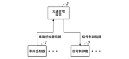
図1は、本実施形態に係る交通管理システムの全体構成図である。 FIG. 1 is an overall configuration diagram of a traffic management system according to the present embodiment.
この交通管理システム(交通管制システム)は、車両感知器1と、信号制御機2と、交通管理装置3と、を備えている。
This traffic management system (traffic control system) includes a
車両感知器1は、例えば超音波式車両感知器および光学式車両感知器(光ビーコン)などであり、道路上の車両を感知して、道路における車両の通行状況を表す車両感知器情報(交通量および占有率)を生成する。この車両感知器情報は、車両感知器1から交通管理装置3に送信される。
The
信号制御機2は、交通管理装置3から送信される信号制御情報に基づいて、信号灯器の動作を制御する。
The
交通管理装置3は、交通管制システムの中央装置であり、車両感知器1から送信される車両感知器情報に基づいて、信号制御機2の制御を行うための信号制御情報を生成するとともに、対象エリア内の交通情報を生成する。
The
次に、交通管理装置3の概略構成について説明する。図2は、交通管理装置3の概略構成を示すブロック図である。
Next, the schematic configuration of the
交通管理装置3は、第1の交通管理部11と、第2の交通管理部12と、を備えている。第1の交通管理部11は、交通管理に係る既存の機能を実現するものであり、第2の交通管理部12は、交通管理に係る新規の機能を実現するものである。このような構成とすることで、交通管理装置3における既存の構成要素に手を加えることなく、交通管理装置3に新たな機能を付加することができる。
The
第1の交通管理部11は、通信部21と、制御部22と、記憶部23と、を備えている。
The first
通信部21は、車両感知器1および信号制御機2と通信を行い、車両感知器1から送信される車両感知器情報を受信し、また、信号制御情報を信号制御機2に送信する。
The
記憶部23は、車両感知器情報、信号制御実績情報、車両感知器配置情報、および道路網構成情報を記憶する。また、記憶部23は、制御部22を構成するプロセッサで実行されるプログラムを記憶する。
The
車両感知器情報は、車両感知器1で収集された車両の通行状況を表す情報であり、具体的には、交通量、すなわち、単位時間(例えば5分)ごとに車両感知器1の位置を通過した車両の台数や、占有率(時間占有率)、すなわち、単位時間内に車両感知器1の位置に車両が存在していた時間の割合などである。
The vehicle detector information is information that represents the traffic status of the vehicle collected by the
信号制御実績情報は、過去および現在運用中の信号制御で用いられた信号制御情報(信号制御パラメータや各ステップ(階梯)の実績値)である。信号制御情報は、交通信号の表示タイミングを決定する要素となる信号制御パラメータの情報であり、具体的には、サイクル長、スプリット、オフセット、およびオフセットの基準となる交差点の番号などを有する制御指令情報やステップ(階梯)毎の実行した秒数、および交差点の番号などで構成される制御実行情報である。 The signal control actual information is the signal control information (signal control parameters and actual values of each step (step)) used in the signal control in the past and present operation. The signal control information is information on signal control parameters that are elements that determine the display timing of a traffic signal, and specifically, a control command having a cycle length, a split, an offset, an intersection number that serves as a reference for the offset, and the like. It is control execution information composed of information, the number of seconds executed for each step (step), the number of intersections, and the like.
車両感知器配置情報は、車両感知器1が設置された位置に関する情報であり、具体的には、車両感知器1が設置されたリンクの番号、リンクの終端から車両感知器1までの距離などである。
The vehicle detector arrangement information is information regarding the position where the
道路網構成情報は、道路網を構成するノードおよびリンクの接続形態や、各リンクの車線数などに関する情報であり、具体的には、リンク(道路)に関する情報として、リンク番号、車線数、リンク長、方向別付加車線(右折専用車線など)の有無および長さなどであり、また、ノード(交差点)に関する情報として、ノード番号、信号現示と通行権付与流入路の関係に関する情報などである。 The road network configuration information is information on the connection form of nodes and links constituting the road network, the number of lanes of each link, and specifically, as information on links (roads), a link number, the number of lanes, and a link. The length, the presence / absence and length of additional lanes for each direction (right turn lane, etc.), and as information on nodes (intersections), information on the relationship between node numbers, signal indications, and inflow routes for which traffic rights are granted. ..
制御部22は、信号制御情報生成部31を備えている。この制御部22は、単一または複数のプロセッサで構成され、信号制御情報生成部31は、記憶部23に記憶されたプログラムをプロセッサで実行することで実現される。
The control unit 22 includes a signal control
信号制御情報生成部31は、車両感知器1から取得した車両感知器情報と、第2の交通管理部12で取得した仮想車両感知器情報とに基づいて、信号制御機2を制御するための信号制御情報を生成する。具体的には、信号制御パラメータ(サイクル長、スプリットおよびオフセット)を算出する。
The signal control
第2の交通管理部12は、制御部41と、記憶部42と、を備えている。
The second
記憶部42は、車両感知器情報、信号制御実績情報、車両感知器配置情報、道路網構成情報、交通状況推計用設定情報、単位エリア定義情報、仮想車両感知器情報生成用設定情報、交通状況詳細情報、仮想車両感知器情報、および信号制御情報を記憶する。また、記憶部42は、制御部41を構成するプロセッサで実行されるプログラムを記憶する。
The storage unit 42 contains vehicle detector information, signal control record information, vehicle detector arrangement information, road network configuration information, traffic condition estimation setting information, unit area definition information, virtual vehicle detector information generation setting information, and traffic status. Stores detailed information, virtual vehicle detector information, and signal control information. Further, the storage unit 42 stores a program executed by the processor constituting the
交通状況推計用設定情報は、交通状況を推計する際に必要となる各種の条件に関する情報である。具体的には、交通状況を推計する際の推計期間、すなわち、交通状況を推計する際に入力する情報(車両感知器情報および信号制御実績情報)の期間である。また、交通状況推計用設定情報は、交通流モデルのパラメータ、例えば、リンクやノードの交通流率(単位時間あたりに通過する車両の台数)、各リンクの法定速度、ならびに各リンクにおける車線の数、車線の幅員および右折レーンの有無などに関する情報である。 The traffic condition estimation setting information is information on various conditions required for estimating the traffic condition. Specifically, it is an estimation period when estimating the traffic condition, that is, a period of information (vehicle detector information and signal control actual information) to be input when estimating the traffic condition. In addition, the setting information for traffic condition estimation includes the parameters of the traffic flow model, for example, the traffic flow rate of links and nodes (the number of vehicles passing per unit time), the legal speed of each link, and the number of lanes in each link. , Information on lane width and the presence or absence of a right turn lane.
単位エリア定義情報は、交通状況を推計する単位となる単位エリアに関する情報であり、具体的には、単位エリアの番号(識別情報)、単位エリアに含まれるリンクの番号、単位エリアに含まれる交差点の番号などである。 The unit area definition information is information about a unit area that is a unit for estimating traffic conditions. Specifically, the unit area number (identification information), the link number included in the unit area, and the intersection included in the unit area. Such as the number of.
仮想車両感知器情報生成用設定情報は、仮想車両感知器情報を生成する際に必要となる各種の条件に関する情報である。この情報は、仮想車両感知器の位置情報、具体的には、仮想車両感知器が設定されたリンクの番号(識別情報)や、リンクの終端からの位置などである。また、この情報は、仮想車両感知器情報を生成する際の収集期間、すなわち、交通状況の推計結果として出力される交通状況詳細情報のうち、仮想車両感知器情報の生成に使用する期間などである。 The setting information for generating virtual vehicle detector information is information related to various conditions required when generating virtual vehicle detector information. This information includes the position information of the virtual vehicle detector, specifically, the link number (identification information) in which the virtual vehicle detector is set, the position from the end of the link, and the like. In addition, this information is collected during the period when the virtual vehicle detector information is generated, that is, the period used for generating the virtual vehicle detector information among the detailed traffic condition information output as the estimation result of the traffic condition. is there.
交通状況詳細情報(図9参照)は、交通状況の推計結果に関する情報であり、各車両の走行軌跡、すなわち各車両の位置の時間的な推移状況(各時刻における各車両の位置)を表す情報であり、具体的には、車両ごとの車両ID、通過時刻、通過位置(リンク番号、リンク終端からの距離など)などである。 The detailed traffic condition information (see FIG. 9) is information on the estimation result of the traffic condition, and represents the traveling locus of each vehicle, that is, the temporal transition status of the position of each vehicle (the position of each vehicle at each time). Specifically, it is a vehicle ID, a passing time, a passing position (link number, a distance from the link end, etc.) for each vehicle.
仮想車両感知器情報は、所定の位置に設定された仮想車両感知器により収集したものとして取り扱われる情報であり、具体的には、車両感知器情報と同様に、交通量および占有率などである。 The virtual vehicle detector information is information that is treated as being collected by a virtual vehicle detector set at a predetermined position, and specifically, like the vehicle detector information, it is traffic volume, occupancy rate, and the like. ..
信号制御情報は、信号制御機2を制御するための、信号制御パラメータ(サイクル長、スプリットおよびオフセット)である。
The signal control information is a signal control parameter (cycle length, split and offset) for controlling the
制御部41は、入力情報取得部51と、単位エリア設定部52と、交通状況推計部53と、仮想車両感知器情報生成部54と、を備えている。この制御部41は、単一または複数のプロセッサで構成され、制御部41の各部は、記憶部42に記憶されたプログラムをプロセッサで実行することで実現される。
The
入力情報取得部51は、第1の交通管理部11から必要な情報を収集するものであり、本実施形態では、第1の交通管理部11から、車両感知器情報、信号制御実績情報、車両感知器配置情報、および道路網構成情報を取得して、それらの情報を記憶部42に記憶する。
The input
単位エリア設定部52は、記憶部42の車両感知器配置情報および道路網構成情報に基づいて、対象エリア内に、交通状況推計部53において交通状況を推計する際の単位となる単位エリア(図4参照)を設定する。
The unit
交通状況推計部53は、記憶部42の交通状況推計用設定情報に基づいて、交通流モデルを用いた推計処理を行い、単位エリア内の交通状況を推計し、交通状況詳細情報(図9参照)、具体的には、各車両の走行軌跡、すなわち各車両の位置の時間的な推移状況を表す情報を生成する。
The traffic
仮想車両感知器情報生成部54は、交通状況推計部53で取得した交通状況詳細情報に基づいて、所定の位置に設定された仮想車両感知器により収集したものとして取り扱われる仮想車両感知器情報(交通量および占有率)を生成する。
The virtual vehicle detector
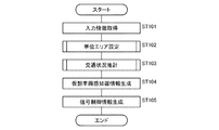
次に、交通管理装置3で行われる処理の手順について説明する。図3は、交通管理装置3で行われる処理の手順を示すフロー図である。
Next, the procedure of the processing performed by the
交通管理装置3では、まず、第2の交通管理部12の入力情報取得部51において、第1の交通管理部11から、車両感知器情報、信号制御実績情報、車両感知器配置情報、および道路網構成情報を取得して、それらの情報を記憶部42に記憶する(ST101)。
In the
次に、単位エリア設定部52において、記憶部42の車両感知器配置情報および道路網構成情報に基づいて、対象エリア内に単位エリアを設定する(ST102)。
Next, the unit
次に、交通状況推計部53において、記憶部42の交通状況推計用設定情報に基づいて、交通流モデルを用いて単位エリア内の交通状況を推計して、交通状況詳細情報を生成する(ST103)。
Next, the traffic
次に、仮想車両感知器情報生成部54において、交通状況推計部53で取得した交通状況詳細情報に基づいて、仮想車両感知器情報を生成する(ST104)。
Next, the virtual vehicle detector
次に、第1の交通管理部11の信号制御情報生成部31において、車両感知器1から取得した車両感知器情報と、仮想車両感知器情報生成部54で取得した仮想車両感知器情報とに基づいて、信号制御情報を生成する(ST105)。
Next, in the signal control
次に、単位エリア設定部52で行われる処理について説明する。図4は、単位エリア設定部52で設定される単位エリアの一例を示す説明図である。
Next, the processing performed by the unit
単位エリア設定部52は、対象エリア内に、交通状況推計部53において交通状況を推計する際の単位となる単位エリアを設定し、この単位エリアを対象として、交通状況推計部53において、交通流モデルを用いた交通状況の推計が行われる。
The unit
道路網は、ノード(交差点)およびそのノードを結ぶリンク(道路)により構成され、リンクには車両感知器1が設置されている。また、ノードには必要に応じて図示しない信号制御機2が設置されている。
The road network is composed of nodes (intersections) and links (roads) connecting the nodes, and a
ここで、本実施形態では、単位エリアが、単位エリア内の交通状況の推計が可能なように設定される。特に本実施形態では、単位エリアの境界位置に車両感知器1が配置されて、単位エリアに流入する交通量を計測することができるように単位エリアが設定される。すなわち、単位エリアの境界に位置するリンクに車両感知器1が配置されて、その境界に位置するリンクごとに流入量(内向きの交通量)を計測することができるように単位エリアが設定される。
Here, in the present embodiment, the unit area is set so that the traffic condition in the unit area can be estimated. In particular, in the present embodiment, the
なお、単位エリアでは、流入する交通量を取得することが重要であり、単位エリアに流入する交通量を取得することで、交通流モデルを用いた推計処理により単位エリア内の交通状況の推計が可能となり、単位エリアからの流出量は、交通流モデルを用いた推計処理による推計結果として取得することができる。 In addition, it is important to acquire the inflowing traffic volume in the unit area, and by acquiring the inflowing traffic volume, the traffic situation in the unit area can be estimated by the estimation process using the traffic flow model. This makes it possible, and the amount of runoff from the unit area can be obtained as an estimation result by estimation processing using a traffic flow model.
また、単位エリアの境界に位置する全てのリンクについて流入量を取得するとよいが、必ずしも単位エリアの境界に位置する全てのリンクについて流入量を取得する必要はない。例えば、住宅地の小さな道路のように交通量が少ないリンクでは、現地調査で取得した交通量の実績値に基づく定数で流入量を与えればよく、また、交通流モデルのパラメータで調整するようにしてもよく、このようにしても、実用上十分な精度で単位エリア内の交通状況を推計することができる。 Further, it is preferable to acquire the inflow amount for all the links located at the boundary of the unit area, but it is not always necessary to acquire the inflow amount for all the links located at the boundary of the unit area. For example, for a link with low traffic volume such as a small road in a residential area, the inflow volume may be given by a constant based on the actual value of the traffic volume acquired in the field survey, and it should be adjusted by the parameters of the traffic flow model. Even in this way, it is possible to estimate the traffic condition in the unit area with practically sufficient accuracy.
また、車両感知器1の配置に変更が生じた場合や、道路網の構成に変更が生じた場合、例えば、車両感知器1の廃止や新設があった場合や、道路が新設された場合には、単位エリアを設定し直す更新処理が行われる。
In addition, when the arrangement of the
次に、仮想車両感知器について説明する。図5は、車両感知器1および仮想車両感知器の配置状況の一例を示す説明図である。
Next, the virtual vehicle detector will be described. FIG. 5 is an explanatory diagram showing an example of the arrangement state of the
本実施形態では、図4に示したように、境界位置に車両感知器1が配置されるように単位エリアを設定して、その単位エリア内の交通状況を推計する。これにより、単位エリア内の任意の位置の交通状況を取得することができる。したがって、境界位置の車両感知器1は必要であるが、単位エリアの内部に位置する車両感知器1は不要となる。このため、境界位置に既設の車両感知器1がない場合には、その位置に車両感知器1を新設し、単位エリアの内部に位置する車両感知器1は廃止することができる。
In the present embodiment, as shown in FIG. 4, a unit area is set so that the
一方、信号制御では、既設の車両感知器1による車両感知器情報を入力情報として制御が行われ、既設の車両感知器1を廃止すると、制御内容を大幅に変更する必要が生じる。そこで、本実施形態では、廃止予定の車両感知器1が設置されている位置に仮想車両感知器を設定して、その仮想車両感知器により収集したものとして取り扱うことができる仮想車両感知器情報を、推計した交通状況に基づいて生成する。これにより、信号制御の制御内容を大幅に変更することなく、車両感知器1を削減することができる。
On the other hand, in signal control, vehicle detector information by the existing
図5(A)に示すように、既設の車両感知器1が存在する場合、図5(B)に示すように、単位エリアを設定すると、既設の車両感知器1のうち、境界位置の車両感知器1は残し、単位エリアの内部に位置する車両感知器1を廃止して、その位置に仮想車両感知器を設定する。また、境界位置に車両感知器1がない場合には、その位置に車両感知器1を新設する。
As shown in FIG. 5 (A), when the existing
なお、図5に示す重要交差点は、横(東西)の流入路と縦(南北)の流入路とで交通の取り合いが発生する交差点であり、信号制御パラメータを生成する際の最小単位となるサブエリア内に1つ設定される。図5に示す例では、この重要交差点において、幹線道路となる横の流入路の他に、従道路となる縦の流入路にも、車両感知器1が設置されている。
The important intersection shown in FIG. 5 is an intersection where traffic competition occurs between the horizontal (east-west) inflow road and the vertical (north-south) inflow road, and is a sub that is the minimum unit when generating signal control parameters. One is set in the area. In the example shown in FIG. 5, at this important intersection, the
ところで、仮想車両感知器情報に基づいて信号制御を行うにあたっては、まず、既設の車両感知器1による車両感知器情報と仮想車両感知器情報とを比較することで、仮想車両感知器情報の精度を確認し、必要な精度を確保できていない場合には、交通状況推計のパラメータを調整し、必要な精度が確認されると、仮想車両感知器情報に基づく制御に移行して、単位エリアの内部に位置する不要な車両感知器1を徐々に廃止するようにするとよい。
By the way, in performing signal control based on the virtual vehicle detector information, first, the accuracy of the virtual vehicle detector information is obtained by comparing the vehicle detector information by the existing
なお、フェイルセーフの観点から、単位エリアの内部に位置する車両感知器1でも、重要交差点に関係する車両感知器1は残しておくようにしてもよい。
From the viewpoint of fail-safe, even in the
次に、単位エリア設定部52で行われる処理の手順について説明する。図6は、単位エリア設定部52で行われる処理の手順を示すフロー図である。
Next, the procedure of the processing performed by the unit
単位エリア設定部52では、まず、記憶部42の車両感知器配置情報に基づいて、既設の車両感知器1の配置状況を確認する(ST201)。また、記憶部42の道路網構成情報に基づいて、道路網の構成を確認する(ST202)。
The unit
次に、仮想車両感知器情報を生成する対象となる仮想車両感知器の位置、すなわち、既設の車両感知器1のうちで廃止可能な車両感知器1の位置を確認する(ST203)。
Next, the position of the virtual vehicle detector for which the virtual vehicle detector information is generated, that is, the position of the
次に、既設の車両感知器1の配置状況と、仮想車両感知器の位置とに基づいて、交通状況を推計する単位となる単位エリアの範囲を決定して、その単位エリアの範囲に関する単位エリア定義情報を生成する(ST204)。このとき、単位エリアの境界位置に車両感知器1が配置されて、この車両感知器1により単位エリアに流入する交通量を取得可能なように、単位エリアが設定される。
Next, based on the arrangement status of the existing
次に、交通状況推計部53で行われる処理について説明する。図7は、交通状況推計部53で用いられる交通流モデルの一例を説明する説明図である。図7(A)は、リンク(道路)に設定されるブロックを説明するものであり、図7(B)は、交通量−密度曲線を表すグラフであり、図7(C)は、隣接するブロック間の交通密度の移動状況を模式的に表したものである。
Next, the processing performed by the traffic
交通状況推計部53は、単位エリアを対象として交通流モデルを用いた推計処理により、単位エリア内の交通状況を推計する。
The traffic
この交通状況の推計では、任意の地点での渋滞の発生状況、道路網の構成、および各リンクの車線数なども考慮する必要があるため、ミクロな車両や車線の取扱いが可能な交通流モデルが必要であり、例えば、東京大学生産技術研究所などで構成される研究グループで開発されたAVENUE(an Advanced & Visual Evaluator for road Networks in Urban arEas)が好適である。 In this traffic situation estimation, it is necessary to consider the occurrence of traffic congestion at any point, the composition of the road network, the number of lanes of each link, etc., so a traffic flow model that can handle micro vehicles and lanes For example, AVENUE (an Advanced & Visual Evaluator for road Networks in Urban arEas) developed by a research group composed of the Institute of Production Technology of the University of Tokyo is suitable.
図7は、AVENUEで用いられるブロック密度法を説明するものであり、このブロック密度法では、図7(A)に示すように、リンク(道路)にブロックを等間隔に設定し、各ブロック内に存在する車両の台数で交通状況を表現する。図7(A)に示す例では、2つの交差点を結ぶリンクが2本の車線を有し、各車線にブロックが設定されている。 FIG. 7 describes a block density method used in AVENUE. In this block density method, as shown in FIG. 7A, blocks are set at equal intervals on a link (road), and blocks are set in each block. The traffic situation is expressed by the number of vehicles existing in. In the example shown in FIG. 7A, the link connecting the two intersections has two lanes, and a block is set in each lane.
ブロック密度法では、図7(B)に示すように、リンクの交通容量(リンク容量)Qc、ジャム密度Kjおよび自由流速度Vfにより決定される交通量−密度曲線が設定され、この交通量−密度曲線に基づいて、図7(C)に示すように、隣接する上流側のブロックi+1と下流側のブロックiとの間の流量(移動交通量)Qi+1,iを求める。具体的には、図7(B)に示す交通量−密度曲線に基づいて、各ブロックの密度から、各ブロックの流出可能量Aout i+1および流入可能量Ain iを求め、その最小値をブロック間の流量Qi+1,iとする。この隣接するブロック間の流量の計算をすべてのブロックを対象にして行う。 In the block density method, as shown in FIG. 7B, a traffic volume-density curve determined by the traffic capacity (link capacity) Qc of the link, the jam density Kj, and the free flow velocity Vf is set, and this traffic volume- Based on the density curve, as shown in FIG. 7C, the flow rate (moving traffic volume) Qi + 1, i between the adjacent upstream block i + 1 and the downstream block i is obtained. Specifically, based on the traffic volume-density curve shown in FIG. 7B, the outflow possible amount A out i + 1 and the inflow possible amount A in i of each block are obtained from the density of each block, and the minimum values thereof are calculated. Let the flow rates between blocks Q i + 1, i . The flow rate between adjacent blocks is calculated for all blocks.
このようにして、ブロック密度法では、各リンクにおける交通量を算出することができるが、さらに、このブロック密度法に、離散的な待ち行列モデルを組み合わせたハイブリッドブロック密度法では、車両の走行状況を1台ずつ再現し、さらに運転者の経路選択行動も取り入れることができ、これにより、各リンクの交通状況を詳細に推計することができる。 In this way, the block density method can calculate the traffic volume at each link, but in the hybrid block density method that combines this block density method with a discrete queuing model, the driving situation of the vehicle Can be reproduced one by one, and the route selection behavior of the driver can also be incorporated, so that the traffic condition of each link can be estimated in detail.
次に、交通状況推計部53で行われる処理の手順について説明する。図8は、交通状況推計部53で行われる処理の手順を示すフロー図である。
Next, the procedure of the processing performed by the traffic
交通状況推計部53では、まず、記憶部42の交通状況推計用設定情報(推計期間)に基づいて、記憶部42の車両感知器情報の中から、推計期間に含まれる車両感知器情報(単位エリアへの流入交通量)を、推計入力情報として取得する(ST301)。また、記憶部42の信号制御実績情報の中から、推計期間に含まれる信号制御実績情報(信号制御パラメータの実績値)を、推計入力情報として取得する(ST302)。なお、推計期間は、推計時点Tより期間N1だけ過去に遡った時点T1(=T−N1)から推計時点Tまでの期間である。
In the traffic
次に、記憶部42の単位エリア定義情報、道路網構成情報、および交通状況推計用設定情報に基づいて、対象とする単位エリアに関する道路網の構成および交通流モデルのパラメータ(交通流率など)を設定する(ST303)。 Next, based on the unit area definition information, the road network configuration information, and the traffic condition estimation setting information of the storage unit 42, the road network configuration and the traffic flow model parameters (traffic flow rate, etc.) regarding the target unit area are used. Is set (ST303).
次に、推計入力情報、すなわち、推計期間の車両感知器情報および信号制御実績情報を交通流モデルに適用して、推計期間における単位エリア内の交通状況を推計する(ST304)。このとき、推計時点T1から順次、推計入力情報を交通流モデルに適用して、推計期間N1における推計結果を取得する。この推計処理は、単位エリアごとに行われ、単位エリアごとの推計結果が得られ、対象とする全ての単位エリアごとの推計結果が、交通状況詳細情報として記憶部42に記憶される。 Next, the estimation input information, that is, the vehicle detector information and the signal control performance information during the estimation period is applied to the traffic flow model to estimate the traffic condition within the unit area during the estimation period (ST304). At this time, the estimation input information is sequentially applied to the traffic flow model from the estimation time point T1 to acquire the estimation result in the estimation period N1. This estimation process is performed for each unit area, the estimation results for each unit area are obtained, and the estimation results for all the target unit areas are stored in the storage unit 42 as detailed traffic condition information.
次に、仮想車両感知器情報生成部54で行われる処理について説明する。図9は、交通状況推計部53で取得した交通状況詳細情報を示す説明図である。
Next, the processing performed by the virtual vehicle detector
交通状況推計部53は、交通流モデルを用いた推計処理により交通状況を推計し、これにより、図9に示すような交通状況詳細情報が得られる。この交通状況詳細情報は、各車両の走行軌跡、すなわち各車両の位置の時間的な推移状況を表している。仮想車両感知器情報生成部54は、図9に示す交通状況詳細情報に基づいて、仮想車両感知器情報を生成する。本実施形態では、仮想車両感知器情報として、仮想車両感知器が設定された位置の交通量および占有率を取得する。
The traffic
図9に示す例では、各ノード(交差点)N1〜N8を結ぶリンク(道路)L1〜L7のうち、リンクL2,L5,L7に仮想車両感知器が設定されており、この仮想車両感知器が設定された位置の交通状況詳細情報から、各仮想車両感知器に対応する仮想車両感知器情報(交通量および占有率)を生成する。本実施形態では、時点Tを基準にした収集期間、具体的には、時点Tから所定時間だけ過去に遡った期間における交通状況詳細情報から、時点Tの仮想車両感知器情報を生成する。なお、収集期間は、交通管理の単位時間(例えば5分)またはその整数倍とするとよい。 In the example shown in FIG. 9, of the links (roads) L1 to L7 connecting the nodes (intersections) N1 to N8, a virtual vehicle detector is set at the links L2, L5, and L7, and the virtual vehicle detector is set. Virtual vehicle detector information (traffic volume and occupancy rate) corresponding to each virtual vehicle detector is generated from the detailed traffic condition information at the set position. In the present embodiment, the virtual vehicle detector information of the time point T is generated from the detailed traffic condition information in the collection period based on the time point T, specifically, the period retroactively by a predetermined time from the time point T. The collection period may be a unit time of traffic management (for example, 5 minutes) or an integral multiple thereof.
ここで、図9に示す交通状況詳細情報は、各車両の走行状況を再現したものであり、各車両の挙動を把握することができ、特に、仮想車両感知器が設定された位置に注目することで、仮想車両感知器の位置を車両がどのように通過したかを把握することができる。これにより、仮想車両感知器の位置での交通量、すなわち、単位時間内に通過した車両の台数を取得することができる。また、仮想車両感知器の位置での占有率(時間占有率)、すなわち、単位時間内に車両が存在していた時間の割合を取得することができる。 Here, the detailed traffic condition information shown in FIG. 9 reproduces the traveling condition of each vehicle, and can grasp the behavior of each vehicle. In particular, pay attention to the position where the virtual vehicle detector is set. This makes it possible to grasp how the vehicle has passed the position of the virtual vehicle detector. As a result, it is possible to acquire the traffic volume at the position of the virtual vehicle detector, that is, the number of vehicles that have passed within a unit time. Further, the occupancy rate (time occupancy rate) at the position of the virtual vehicle detector, that is, the ratio of the time during which the vehicle was present within the unit time can be acquired.
以上のように、本出願において開示する技術の例示として、実施形態を説明した。しかしながら、本開示における技術は、これに限定されず、変更、置き換え、付加、省略などを行った実施形態にも適用できる。また、上記の実施形態で説明した各構成要素を組み合わせて、新たな実施形態とすることも可能である。 As described above, embodiments have been described as an example of the techniques disclosed in this application. However, the technique in the present disclosure is not limited to this, and can be applied to embodiments in which changes, replacements, additions, omissions, etc. have been made. It is also possible to combine the components described in the above embodiments to form a new embodiment.
例えば、前記の実施形態では、交通状況の推計結果から取得した仮想車両感知器情報を用いて信号制御を行うようにしたが、仮想車両感知器情報を用いて、車両の運転者に提供する交通情報を生成するようにしてもよい。この場合も、信号制御の場合と同様に、交通情報を生成するための現行の制御内容を大幅に変更することなく、車両感知器を削減することができる。 For example, in the above embodiment, the signal control is performed using the virtual vehicle detector information acquired from the estimation result of the traffic condition, but the traffic provided to the driver of the vehicle by using the virtual vehicle detector information. Information may be generated. In this case as well, as in the case of signal control, the number of vehicle detectors can be reduced without significantly changing the current control contents for generating traffic information.
また、前記の実施形態では、既設の車両感知器の廃止を前提にして、その既設の車両感知器の代わりになる仮想車両感知器を設定して、その仮想車両感知器に関する仮想車両感知器情報を生成するようにしたが、信号制御の精度を向上させるなど、交通管制システムの機能を高める目的で、既設の車両感知器とは別の位置に仮想車両感知器を設定して、その仮想車両感知器に関する仮想車両感知器情報と、既設の車両感知器による車両感知器情報とに基づいて制御を行うようにしてもよい。 Further, in the above-described embodiment, on the premise that the existing vehicle detector is abolished, a virtual vehicle detector that replaces the existing vehicle detector is set, and virtual vehicle detector information regarding the virtual vehicle detector is set. However, for the purpose of improving the function of the traffic control system, such as improving the accuracy of signal control, a virtual vehicle detector is set at a position different from the existing vehicle detector, and the virtual vehicle is set. Control may be performed based on the virtual vehicle detector information regarding the detector and the vehicle detector information by the existing vehicle detector.
また、本実施形態では、交通管理装置を、交通管理に係る既存の機能を実現する第1の交通管理部と、交通管理に係る新規の機能を実現する第2の交通管理部とで分けて構成し、既存の機能に新規の機能を付加するようにしたが、第1の交通管理部の機能と第2の交通管理部の機能をひとつにまとめて、既存の装置(第1の交通管理部)と入れ替えるように交通管理装置を構成するようにしてもよい。 Further, in the present embodiment, the traffic management device is divided into a first traffic management unit that realizes an existing function related to traffic management and a second traffic management unit that realizes a new function related to traffic management. It was configured to add new functions to existing functions, but the functions of the first traffic management department and the second traffic management department were combined into one and the existing equipment (first traffic management). The traffic management device may be configured so as to replace the part).
また、前記の実施形態では、交通管理装置自身で単位エリアの範囲を決定するようにしたが、ユーザが単位エリアの範囲を決定して、ユーザにより入力された単位エリアに関する情報に基づいて単位エリアを設定する処理が交通管理装置で行われるようにしてもよい。 Further, in the above-described embodiment, the range of the unit area is determined by the traffic management device itself, but the user determines the range of the unit area, and the unit area is based on the information regarding the unit area input by the user. The process of setting may be performed by the traffic management device.
本発明に係る交通管理装置、交通管理システムおよび交通管理方法は、信号制御などの交通管理の制御内容を大幅に変更することなく、車両感知器を削減することができる効果を有し、対象エリア内に設置された車両感知器により取得した車両感知器情報に基づいて、対象エリア内の交通管理を行う交通管理装置、交通管理システムおよび交通管理方法などとして有用である。 The traffic management device, the traffic management system, and the traffic management method according to the present invention have an effect that the number of vehicle detectors can be reduced without significantly changing the control contents of the traffic management such as signal control, and the target area. It is useful as a traffic management device, a traffic management system, a traffic management method, etc. that manages traffic in the target area based on the vehicle detector information acquired by the vehicle detector installed inside.
1 車両感知器
2 信号制御機
3 交通管理装置
21 通信部
22 制御部
23 記憶部
41 制御部
42 記憶部
1
Claims (9)
前記車両感知器から前記車両感知器情報を受信する通信部と、
前記車両感知器情報に基づいて、前記エリア内の交通管理に係る情報処理を行う制御部と、を備え、
前記制御部は、
前記車両感知器情報、および前記エリア内に設置された信号制御機に関する信号制御実績情報に基づいて、前記エリアを対象として交通流モデルを用いた推計処理を行って、前記エリア内の交通状況に関する情報を取得し、
前記エリアの交通状況に関する情報に基づいて、前記エリア内の所定の位置に車両感知器が設置されたとみなす仮想車両感知器により取得したものとして取り扱う仮想車両感知器情報を生成することを特徴とする交通管理装置。 Based on the acquired vehicle detector information by vehicle detectors installed in the d rear, a traffic management device that performs traffic management in e rear,
A communication unit that receives the vehicle detector information from the vehicle detector, and
On the basis of the vehicle detector information, and a control unit for performing information processing according to the traffic management before disappeared in the rear,
Wherein,
Before SL based on the signal control result information relating to vehicle detectors information, and pre disappeared installed signal controller in the rear, before performing the estimation processing using the traffic flow model disappeared rear as a target, before Symbol to obtain information about the traffic situation in the d rear,
The front based on the information on traffic conditions disappeared rear, generates a virtual vehicle detectors information handled as acquired by the virtual vehicle detectors regarded as vehicle detector is installed at a predetermined position before disappear in the rear A traffic management device featuring.
前記通信部は、前記信号制御情報を前記信号制御機に送信することを特徴とする請求項1に記載の交通管理装置。 The control unit generates signal control information for controlling the signal controller based on the virtual vehicle detector information.
The traffic management device according to claim 1, wherein the communication unit transmits the signal control information to the signal controller.
前記交通管理装置は、
前記車両感知器から前記車両感知器情報を受信する通信部と、
前記車両感知器情報に基づいて、前記エリア内の交通管理に係る情報処理を行う制御部と、を備え、
前記制御部は、
前記車両感知器情報、および前記エリア内に設置された信号制御機に関する信号制御実績情報に基づいて、前記エリアを対象として交通流モデルを用いた推計処理を行って、前記エリア内の交通状況に関する情報を取得し、
前記エリアの交通状況に関する情報に基づいて、前記エリア内の所定の位置に車両感知器が設置されたとみなす仮想車両感知器により取得したものとして取り扱う仮想車両感知器情報を生成することを特徴とする交通管理システム。 A vehicle detectors installed in the d rear, based on the acquired vehicle sensor information by the vehicle detector, a traffic management system comprising a traffic management device that performs traffic management in e rear, a,
The traffic management device is
A communication unit that receives the vehicle detector information from the vehicle detector, and
On the basis of the vehicle detector information, and a control unit for performing information processing according to the traffic management before disappeared in the rear,
Wherein,
Before SL based on the signal control result information relating to vehicle detectors information, and pre disappeared installed signal controller in the rear, before performing the estimation processing using the traffic flow model disappeared rear as a target, before Symbol to obtain information about the traffic situation in the d rear,
The front based on the information on traffic conditions disappeared rear, generates a virtual vehicle detectors information handled as acquired by the virtual vehicle detectors regarded as vehicle detector is installed at a predetermined position before disappear in the rear A traffic management system featuring.
前記車両感知器情報、および前記エリア内に設置された信号制御機に関する信号制御実績情報に基づいて、前記エリアを対象として交通流モデルを用いた推計処理を行って、前記エリア内の交通状況に関する情報を取得し、
前記エリアの交通状況に関する情報に基づいて、前記エリア内の所定の位置に車両感知器が設置されたとみなす仮想車両感知器により取得したものとして取り扱う仮想車両感知器情報を生成し、
前記車両感知器情報および前記仮想車両感知器情報に基づいて、前記信号制御機を制御する信号制御情報を生成することを特徴とする交通管理方法。 A traffic management system, based on the acquired vehicle detector information by vehicle detectors installed in the d rear, a traffic management method for performing traffic management in e rear,
Before SL based on the signal control result information relating to vehicle detectors information, and pre disappeared installed signal controller in the rear, before performing the estimation processing using the traffic flow model disappeared rear as a target, before Symbol to obtain information about the traffic situation in the d rear,
Before based on the information on traffic conditions disappeared rear, generates a virtual vehicle detectors information handled as acquired by the virtual vehicle detectors regarded as vehicle detector is installed at a predetermined position before disappear in the rear,
A traffic management method comprising generating signal control information for controlling the signal controller based on the vehicle detector information and the virtual vehicle detector information.
Priority Applications (2)
| Application Number | Priority Date | Filing Date | Title |
|---|---|---|---|
| JP2017136000A JP6899528B2 (en) | 2017-07-12 | 2017-07-12 | Traffic management equipment, traffic management system and traffic management method |
| PCT/JP2018/020685 WO2019012832A1 (en) | 2017-07-12 | 2018-05-30 | Traffic management device, traffic management system, and traffic management method |
Applications Claiming Priority (1)
| Application Number | Priority Date | Filing Date | Title |
|---|---|---|---|
| JP2017136000A JP6899528B2 (en) | 2017-07-12 | 2017-07-12 | Traffic management equipment, traffic management system and traffic management method |
Publications (3)
| Publication Number | Publication Date |
|---|---|
| JP2019020799A JP2019020799A (en) | 2019-02-07 |
| JP2019020799A5 JP2019020799A5 (en) | 2020-08-20 |
| JP6899528B2 true JP6899528B2 (en) | 2021-07-07 |
Family
ID=65002117
Family Applications (1)
| Application Number | Title | Priority Date | Filing Date |
|---|---|---|---|
| JP2017136000A Active JP6899528B2 (en) | 2017-07-12 | 2017-07-12 | Traffic management equipment, traffic management system and traffic management method |
Country Status (2)
| Country | Link |
|---|---|
| JP (1) | JP6899528B2 (en) |
| WO (1) | WO2019012832A1 (en) |
Families Citing this family (3)
| Publication number | Priority date | Publication date | Assignee | Title |
|---|---|---|---|---|
| WO2021058100A1 (en) * | 2019-09-25 | 2021-04-01 | Huawei Technologies Co., Ltd. | Multisensory learning system for traffic prediction |
| CN110969871B (en) * | 2019-12-18 | 2020-11-24 | 浙江大学 | Intelligent traffic light control system and control method |
| JP7347367B2 (en) * | 2020-08-11 | 2023-09-20 | トヨタ自動車株式会社 | Energy supply system, information processing device, and method |
Family Cites Families (5)
| Publication number | Priority date | Publication date | Assignee | Title |
|---|---|---|---|---|
| JP2006343814A (en) * | 2005-06-07 | 2006-12-21 | Sumitomo Electric Ind Ltd | Traffic control system and on-vehicle device to transmit information to this system |
| JP6404572B2 (en) * | 2014-02-05 | 2018-10-10 | パナソニック株式会社 | Signal control apparatus, signal control system, and signal control method |
| JP6292555B2 (en) * | 2014-09-19 | 2018-03-14 | パナソニックIpマネジメント株式会社 | Traffic management device, traffic management system, and traffic management method |
| JP6226300B2 (en) * | 2014-09-19 | 2017-11-08 | パナソニックIpマネジメント株式会社 | Traffic information generating apparatus and traffic information generating method |
| SG11201705958PA (en) * | 2015-02-23 | 2017-08-30 | Sumitomo Electric Industries | Traffic index generation device, traffic index generation method, and computer program |
-
2017
- 2017-07-12 JP JP2017136000A patent/JP6899528B2/en active Active
-
2018
- 2018-05-30 WO PCT/JP2018/020685 patent/WO2019012832A1/en active Application Filing
Also Published As
| Publication number | Publication date |
|---|---|
| JP2019020799A (en) | 2019-02-07 |
| WO2019012832A1 (en) | 2019-01-17 |
Similar Documents
| Publication | Publication Date | Title |
|---|---|---|
| Genders et al. | Impact of connected vehicle on work zone network safety through dynamic route guidance | |
| US9599488B2 (en) | Method and apparatus for providing navigational guidance using the states of traffic signal | |
| JP4969814B2 (en) | Road traffic situation grasp system | |
| Geroliminis et al. | Prediction of arrival profiles and queue lengths along signalized arterials by using a Markov decision process | |
| WO2015166876A1 (en) | Traffic signal control device, traffic signal control method, and computer program | |
| JP6899528B2 (en) | Traffic management equipment, traffic management system and traffic management method | |
| JP7028167B2 (en) | Traffic control support system, traffic control support method and program | |
| CN102288193A (en) | Motor vehicle travel route determination method based on historical data | |
| JP2009259158A (en) | Traffic state simulation device, and program | |
| CN104537851A (en) | Real-time feedback dynamic traffic signal control system | |
| JP2005182219A (en) | Traffic signal controller and traffic signal control method and storage medium | |
| Knoop | Introduction to traffic flow theory: An introduction with exercises | |
| CN113223293B (en) | Road network simulation model construction method and device and electronic equipment | |
| Yang et al. | Effects of left-turn waiting areas on capacity and level of service of signalized intersections | |
| Hans et al. | Clustering approach for assessing the travel time variability of arterials | |
| KR101123967B1 (en) | Traffic congestion prediction system, prediction method and recording medium thereof | |
| KR102329826B1 (en) | Device and method for artificial intelligence-based traffic signal control | |
| EP3594920A1 (en) | Method for generating a traffic control signal | |
| JP5898553B2 (en) | Traffic flow prediction device, traffic flow prediction method, and traffic flow prediction program | |
| JP7276964B2 (en) | TRAFFIC INDICATOR CALCULATION DEVICE, CALCULATION METHOD, TRAFFIC SIGNAL CONTROL SYSTEM, AND COMPUTER PROGRAM | |
| JP7225303B2 (en) | Accident forecast system and accident forecast method | |
| JP2018018210A (en) | Signal control device, signal control system, signal control method and program | |
| JP6655831B2 (en) | Signal control device and signal control method | |
| JP6292555B2 (en) | Traffic management device, traffic management system, and traffic management method | |
| CN112797994A (en) | Method for determining estimated arrival time of route, and related device and server |
Legal Events
| Date | Code | Title | Description |
|---|---|---|---|
| A521 | Written amendment |
Free format text: JAPANESE INTERMEDIATE CODE: A523 Effective date: 20200709 |
|
| A621 | Written request for application examination |
Free format text: JAPANESE INTERMEDIATE CODE: A621 Effective date: 20200709 |
|
| TRDD | Decision of grant or rejection written | ||
| A01 | Written decision to grant a patent or to grant a registration (utility model) |
Free format text: JAPANESE INTERMEDIATE CODE: A01 Effective date: 20210427 |
|
| A61 | First payment of annual fees (during grant procedure) |
Free format text: JAPANESE INTERMEDIATE CODE: A61 Effective date: 20210526 |
|
| R151 | Written notification of patent or utility model registration |
Ref document number: 6899528 Country of ref document: JP Free format text: JAPANESE INTERMEDIATE CODE: R151 |