JP6896712B2 - Channel configuration for coexistence on shared communication media - Google Patents
Channel configuration for coexistence on shared communication media Download PDFInfo
- Publication number
- JP6896712B2 JP6896712B2 JP2018515299A JP2018515299A JP6896712B2 JP 6896712 B2 JP6896712 B2 JP 6896712B2 JP 2018515299 A JP2018515299 A JP 2018515299A JP 2018515299 A JP2018515299 A JP 2018515299A JP 6896712 B2 JP6896712 B2 JP 6896712B2
- Authority
- JP
- Japan
- Prior art keywords
- resource elements
- uplink control
- access terminal
- uplink data
- signaling
- Prior art date
- Legal status (The legal status is an assumption and is not a legal conclusion. Google has not performed a legal analysis and makes no representation as to the accuracy of the status listed.)
- Active
Links
- 238000004891 communication Methods 0.000 title claims description 85
- 230000011664 signaling Effects 0.000 claims description 117
- 238000000034 method Methods 0.000 claims description 59
- 238000013475 authorization Methods 0.000 claims description 37
- 241000700159 Rattus Species 0.000 description 39
- 230000015654 memory Effects 0.000 description 31
- 230000005540 biological transmission Effects 0.000 description 20
- 238000013461 design Methods 0.000 description 19
- 238000010586 diagram Methods 0.000 description 12
- 238000005516 engineering process Methods 0.000 description 12
- 230000006870 function Effects 0.000 description 9
- 238000001514 detection method Methods 0.000 description 4
- 230000007774 longterm Effects 0.000 description 3
- 230000007246 mechanism Effects 0.000 description 2
- 239000013589 supplement Substances 0.000 description 2
- 230000002747 voluntary effect Effects 0.000 description 2
- 230000009286 beneficial effect Effects 0.000 description 1
- 230000000903 blocking effect Effects 0.000 description 1
- 239000000969 carrier Substances 0.000 description 1
- 230000001413 cellular effect Effects 0.000 description 1
- 230000008859 change Effects 0.000 description 1
- 125000004122 cyclic group Chemical group 0.000 description 1
- 238000009792 diffusion process Methods 0.000 description 1
- 230000002045 lasting effect Effects 0.000 description 1
- 239000006249 magnetic particle Substances 0.000 description 1
- 238000004519 manufacturing process Methods 0.000 description 1
- 230000003287 optical effect Effects 0.000 description 1
- 239000002245 particle Substances 0.000 description 1
- 230000008569 process Effects 0.000 description 1
- 238000012545 processing Methods 0.000 description 1
- 238000013468 resource allocation Methods 0.000 description 1
- 230000004044 response Effects 0.000 description 1
- 230000003595 spectral effect Effects 0.000 description 1
- 238000001228 spectrum Methods 0.000 description 1
- 230000032258 transport Effects 0.000 description 1
Images


Classifications
-
- H—ELECTRICITY
- H04—ELECTRIC COMMUNICATION TECHNIQUE
- H04W—WIRELESS COMMUNICATION NETWORKS
- H04W72/00—Local resource management
- H04W72/20—Control channels or signalling for resource management
- H04W72/21—Control channels or signalling for resource management in the uplink direction of a wireless link, i.e. towards the network
-
- H—ELECTRICITY
- H04—ELECTRIC COMMUNICATION TECHNIQUE
- H04W—WIRELESS COMMUNICATION NETWORKS
- H04W72/00—Local resource management
- H04W72/04—Wireless resource allocation
- H04W72/044—Wireless resource allocation based on the type of the allocated resource
- H04W72/0446—Resources in time domain, e.g. slots or frames
-
- H—ELECTRICITY
- H04—ELECTRIC COMMUNICATION TECHNIQUE
- H04W—WIRELESS COMMUNICATION NETWORKS
- H04W72/00—Local resource management
- H04W72/20—Control channels or signalling for resource management
- H04W72/23—Control channels or signalling for resource management in the downlink direction of a wireless link, i.e. towards a terminal
-
- H—ELECTRICITY
- H04—ELECTRIC COMMUNICATION TECHNIQUE
- H04W—WIRELESS COMMUNICATION NETWORKS
- H04W76/00—Connection management
- H04W76/20—Manipulation of established connections
- H04W76/27—Transitions between radio resource control [RRC] states
-
- H—ELECTRICITY
- H04—ELECTRIC COMMUNICATION TECHNIQUE
- H04W—WIRELESS COMMUNICATION NETWORKS
- H04W72/00—Local resource management
- H04W72/12—Wireless traffic scheduling
- H04W72/1215—Wireless traffic scheduling for collaboration of different radio technologies
-
- H—ELECTRICITY
- H04—ELECTRIC COMMUNICATION TECHNIQUE
- H04W—WIRELESS COMMUNICATION NETWORKS
- H04W74/00—Wireless channel access
- H04W74/08—Non-scheduled access, e.g. ALOHA
- H04W74/0808—Non-scheduled access, e.g. ALOHA using carrier sensing, e.g. carrier sense multiple access [CSMA]
Landscapes
- Engineering & Computer Science (AREA)
- Computer Networks & Wireless Communication (AREA)
- Signal Processing (AREA)
- Mobile Radio Communication Systems (AREA)
Description
関連出願の相互参照
[0001]本出願は、本出願の譲受人に譲渡され、その全体が参照により本明細書に明確に組み込まれる、2015年9月24日に出願された「Channel Configuration in a Shared Communication Medium」と題する米国仮出願第62/222,867号の利益を主張する。
Cross-reference of related applications
[0001] The application is referred to as "Channel Configuration in a Shared Communication Medium" filed on September 24, 2015, which is transferred to the assignee of this application and is expressly incorporated herein by reference in its entirety. Claim the interests of US Provisional Application No. 62 / 222,867.
[0002]本開示の態様は、一般に電気通信に関し、より詳細には、共有通信媒体上での動作などに関する。 [0002] Aspects of the present disclosure relate generally to telecommunications, and more specifically to operations on shared communication media and the like.
[0003]ワイヤレス通信システムは、音声、データ、マルチメディアなど、様々なタイプの通信コンテンツを提供するために広く展開されている。典型的なワイヤレス通信システムは、利用可能なシステムリソース(たとえば、帯域幅、送信電力など)を共有することによって複数のユーザとの通信をサポートすることが可能な多元接続システムである。そのような多元接続システムの例としては、符号分割多元接続(CDMA)システム、時分割多元接続(TDMA)システム、周波数分割多元接続(FDMA)システム、および直交周波数分割多元接続(OFDMA)システムなどがある。これらのシステムは、しばしば、第3世代パートナーシッププロジェクト(3GPP(登録商標):Third Generation Partnership Project)によって提供されるロングタームエボリューション(LTE(登録商標):Long Term Evolution)、第3世代パートナーシッププロジェクト2(3GPP2:Third Generation Partnership Project 2)によって提供されるウルトラモバイルブロードバンド(UMB:Ultra Mobile Broadband)およびエボリューションデータオプティマイズド(EV−DO:Evolution Data Optimized)、米国電気電子技術者協会(IEEE)によって提供される802.11などの規格に準拠して展開される。 [0003] Wireless communication systems are widely deployed to provide various types of communication content, such as voice, data, and multimedia. A typical wireless communication system is a multiple access system that can support communication with multiple users by sharing available system resources (eg, bandwidth, transmit power, etc.). Examples of such multiple access systems include code division multiple access (CDMA) systems, time division multiple access (TDMA) systems, frequency division multiple access (FDMA) systems, and orthogonal frequency division multiple access (OFDA) systems. is there. These systems are often provided by the 3GPP (3GPP®: Third Generation Partnership Project) Long Term Evolution (LTE®: Long Term Evolution), 3rd Generation Partnership Project 2 ( 3GPP2: Ultra Mobile Broadband (UMB) and Evolution Data Optimized (EV-DO) provided by Third Generation Partnership Project 2), provided by the American Association of Electrical and Electronic Engineers (IEEE) It is developed in accordance with standards such as 802.11.
[0004]セルラーネットワークでは、「マクロセル」アクセスポイントが、ある地理的エリアにわたる多数のユーザに接続性およびカバレージを与える。地理的領域にわたって良好なカバレージを与えるために、マクロネットワーク展開が、慎重に計画され、設計され、インプリメントされる。住居およびオフィスビルのためになど、屋内または他の特定の地理的カバレージを改善するために、追加の「スモールセル」、一般的に、低電力アクセスポイントが、従来のマクロネットワークを補うために最近展開され始めた。スモールセルアクセスポイントはまた、漸進的キャパシティ増大、よりリッチなユーザエクスペリエンスなどを与え得る。 [0004] In cellular networks, "macrocell" access points provide connectivity and coverage to a large number of users across a geographic area. Macro network deployments are carefully planned, designed and implemented to provide good coverage across geographic areas. Additional "small cells", generally low power access points, have recently been added to supplement traditional macro networks to improve indoor or other specific geographic coverage, such as for residential and office buildings. It has begun to be deployed. Small cell access points can also provide gradual capacity growth, a richer user experience, and more.
[0005]スモールセルLTE動作が、たとえば、ワイヤレスローカルエリアネットワーク(WLAN)技術によって使用される無認可国内情報インフラストラクチャ(U−NII:Unlicensed National Information Infrastructure)帯域などの無認可周波数スペクトルに拡張された。スモールセルLTE動作のこの拡張は、LTEシステムのスペクトル効率、したがってキャパシティを増加させるように設計される。しかしながら、それは、一般に、同じ無認可帯域を利用する他の無線アクセス技術(RAT)、最も顕著には、一般に「Wi−Fi(登録商標)」と呼ばれるIEEE802.11x WLAN技術の動作と共存する必要があり得る。 [0005] Small cell LTE operations have been extended to unlicensed frequency spectra, such as the Unlicensed National Information Infrastructure (U-NII) band used by wireless local area network (WLAN) technology. This extension of small cell LTE operation is designed to increase the spectral efficiency, and thus capacity, of the LTE system. However, it needs to co-exist with the operation of other wireless access technologies (RATs) that generally utilize the same unlicensed band, most notably the IEEE802.11x WLAN technology commonly referred to as "Wi-Fi®". possible.
[0006]以下の概要は、本開示の様々な態様の説明を助けるためのみに与えられる概観であり、態様の限定ではなく、態様の例示のみのために与えられる。 [0006] The following summary is an overview provided solely to aid in the description of the various aspects of the present disclosure, and is provided solely for the purpose of exemplifying aspects, not limiting the embodiments.
[0007]一例では、通信方法が開示される。本方法は、たとえば、アップリンク制御チャネルを搬送するためのリソースエレメントのセットを選択することと、リソースエレメントの選択されたセットに関連する1つまたは複数の構成パラメータを含む構成メッセージを1つまたは複数のアクセス端末に送信することと、リソースエレメントの選択されたセットを介して1つまたは複数のアクセス端末からアップリンク制御シグナリングを受信することとを含み得る。 [0007] In one example, the communication method is disclosed. The method, for example, selects a set of resource elements to carry an uplink control channel and one or more configuration messages containing one or more configuration parameters associated with the selected set of resource elements. It may include sending to multiple access terminals and receiving uplink control signaling from one or more access terminals via a selected set of resource elements.
[0008]別の例では、通信装置が開示される。本装置は、たとえば、少なくとも1つのプロセッサと、少なくとも1つのプロセッサに結合された少なくとも1つのメモリと、少なくとも1つのトランシーバとを含み得る。少なくとも1つのプロセッサおよび少なくとも1つのメモリは、アップリンク制御チャネルを搬送するためのリソースエレメントのセットを選択するように構成され得る。少なくとも1つのトランシーバは、リソースエレメントの選択されたセットに関連する1つまたは複数の構成パラメータを含む構成メッセージを1つまたは複数のアクセス端末に送信することと、リソースエレメントの選択されたセットを介して1つまたは複数のアクセス端末からアップリンク制御シグナリングを受信することとを行うように構成され得る。 [0008] In another example, the communication device is disclosed. The device may include, for example, at least one processor, at least one memory coupled to at least one processor, and at least one transceiver. At least one processor and at least one memory may be configured to select a set of resource elements to carry the uplink control channel. At least one transceiver sends a configuration message containing one or more configuration parameters associated with a selected set of resource elements to one or more access terminals, and through the selected set of resource elements. It may be configured to receive uplink control signaling from one or more access terminals.
[0009]別の例では、別の通信装置が開示される。本装置は、たとえば、アップリンク制御チャネルを搬送するためのリソースエレメントのセットを選択するための手段と、リソースエレメントの選択されたセットに関連する1つまたは複数の構成パラメータを含む構成メッセージを1つまたは複数のアクセス端末に送信するための手段と、リソースエレメントの選択されたセットを介して1つまたは複数のアクセス端末からアップリンク制御シグナリングを受信するための手段とを含み得る。 [0009] In another example, another communication device is disclosed. The device provides, for example, a means for selecting a set of resource elements to carry an uplink control channel and a configuration message containing one or more configuration parameters associated with the selected set of resource elements. It may include means for transmitting to one or more access terminals and means for receiving uplink control signaling from one or more access terminals via a selected set of resource elements.
[0010]別の例では、少なくとも1つのプロセッサによって実行されたとき、少なくとも1つのプロセッサに通信のための動作を実施させる一時的または非一時的コンピュータ可読媒体が開示される。本コンピュータ可読媒体は、たとえば、アップリンク制御チャネルを搬送するためのリソースエレメントのセットを選択するためのコードと、リソースエレメントの選択されたセットに関連する1つまたは複数の構成パラメータを含む構成メッセージを1つまたは複数のアクセス端末に送信するためのコードと、リソースエレメントの選択されたセットを介して1つまたは複数のアクセス端末からアップリンク制御シグナリングを受信するためのコードとを含み得る。 [0010] In another example, a temporary or non-transitory computer-readable medium that causes at least one processor to perform an operation for communication when executed by at least one processor is disclosed. The computer-readable medium is, for example, a configuration message containing code for selecting a set of resource elements to carry an uplink control channel and one or more configuration parameters associated with the selected set of resource elements. Can include a code for transmitting to one or more access terminals and a code for receiving uplink control signaling from one or more access terminals via a selected set of resource elements.
[0011]別の例では、別の通信方法が開示される。本方法は、たとえば、アクセスポイントから、アップリンク制御チャネルのための1つまたは複数の構成パラメータを含む構成メッセージを受信することと、構成メッセージに基づいて、アップリンク制御チャネルを搬送するように構成されたリソースエレメントのセットを決定することと、リソースエレメントの決定されたセットを介してアクセスポイントにアップリンク制御シグナリングを送信することとを含み得る。 [0011] In another example, another communication method is disclosed. The method is configured to, for example, receive a configuration message from an access point that includes one or more configuration parameters for the uplink control channel and to carry the uplink control channel based on the configuration message. It may include determining a determined set of resource elements and sending uplink control signaling to the access point through the determined set of resource elements.
[0012]別の例では、別の通信装置が開示される。本装置は、たとえば、少なくとも1つのプロセッサと、少なくとも1つのプロセッサに結合された少なくとも1つのメモリと、少なくとも1つのトランシーバとを含み得る。少なくとも1つのトランシーバは、アクセスポイントから、アップリンク制御チャネルのための1つまたは複数の構成パラメータを含む構成メッセージを受信するように構成され得る。少なくとも1つのプロセッサおよび少なくとも1つのメモリは、構成メッセージに基づいて、アップリンク制御チャネルを搬送するように構成されたリソースエレメントのセットを決定するように構成され得、ここにおいて、少なくとも1つのトランシーバは、リソースエレメントの決定されたセットを介してアクセスポイントにアップリンク制御シグナリングを送信するようにさらに構成される。 [0012] In another example, another communication device is disclosed. The device may include, for example, at least one processor, at least one memory coupled to at least one processor, and at least one transceiver. At least one transceiver may be configured to receive a configuration message from the access point that includes one or more configuration parameters for the uplink control channel. At least one processor and at least one memory can be configured to determine a set of resource elements configured to carry uplink control channels based on configuration messages, where at least one transceiver is used. , Further configured to send uplink control signaling to the access point through a determined set of resource elements.
[0013]別の例では、別の通信装置が開示される。本装置は、たとえば、アクセスポイントから、アップリンク制御チャネルのための1つまたは複数の構成パラメータを含む構成メッセージを受信するための手段と、構成メッセージに基づいて、アップリンク制御チャネルを搬送するように構成されたリソースエレメントのセットを決定するための手段と、リソースエレメントの決定されたセットを介してアクセスポイントにアップリンク制御シグナリングを送信するための手段とを含み得る。 [0013] In another example, another communication device is disclosed. The device transports, for example, a means for receiving a configuration message containing one or more configuration parameters for an uplink control channel from an access point and an uplink control channel based on the configuration message. It may include means for determining a set of resource elements configured in, and means for transmitting uplink control signaling to the access point through the determined set of resource elements.
[0014]別の例では、少なくとも1つのプロセッサによって実行されたとき、少なくとも1つのプロセッサに通信のための動作を実施させる別の一時的または非一時的コンピュータ可読媒体が開示される。本コンピュータ可読媒体は、たとえば、アクセスポイントから、アップリンク制御チャネルのための1つまたは複数の構成パラメータを含む構成メッセージを受信するためのコードと、構成メッセージに基づいて、アップリンク制御チャネルを搬送するように構成されたリソースエレメントのセットを決定するためのコードと、リソースエレメントの決定されたセットを介してアクセスポイントにアップリンク制御シグナリングを送信するためのコードとを含み得る。 [0014] In another example, another temporary or non-transitory computer-readable medium is disclosed that causes at least one processor to perform an operation for communication when executed by at least one processor. The computer-readable medium carries the uplink control channel based on, for example, a code for receiving a configuration message containing one or more configuration parameters for the uplink control channel from an access point and the configuration message. It may include code for determining a set of resource elements configured to do so and code for transmitting uplink control signaling to the access point through the determined set of resource elements.
[0015]添付の図面は、本開示の様々な態様の説明を助けるために提示され、態様の限定ではなく、態様の例示のみのために与えられる。
[0027]本開示は、一般に共有通信媒体上での動作に関する。そのような通信媒体への干渉および不確かなアクセスの可能性に照らしてフレキシビリティを与えるために、物理アップリンク制御チャネル(PUCCH)などのアップリンク制御チャネルは、それらのリソース割当てに関して動的に構成され得る。所与の時間におけるアップリンク制御チャネルのためのアクセスポイントによって選択されたリソースが、構成メッセージなどを介してアクセスポイントによってサービスされているアクセス端末と協調され得る。構成メッセージは、ブロードキャスト/マルチキャストシグナリングとユニキャストシグナリングの両方を含む様々な方法で送られ得、サブフレーム識別子、シンボル期間識別子、サブキャリア識別子などを含み得る。 [0027] The present disclosure generally relates to operation on a shared communication medium. Uplink control channels, such as physical uplink control channels (PUCCH), are dynamically configured with respect to their resource allocation to provide flexibility in the light of possible interference and uncertain access to such communication media. Can be done. The resources selected by the access point for the uplink control channel at a given time can be coordinated with the access terminal being serviced by the access point, such as through a configuration message. Configuration messages can be sent in a variety of ways, including both broadcast / multicast signaling and unicast signaling, and can include subframe identifiers, symbol period identifiers, subcarrier identifiers, and the like.
[0028]また、PUCCHなどのアップリンク制御チャネルを物理アップリンク共有チャネル(PUSCH)などのアップリンクデータチャネルと多重化するための追加の拡張が与えられる。たとえば、アップリンクデータチャネルのためのリソースをアクセス端末に割り当てる許可メッセージが、さらに、アップリンク制御チャネルの動的構成に関するアップリンクデータチャネルのタイミング(たとえば、PUCCHによってさまざまに占有され得る、異なるサブキャリアインターレース中のPUSCHの異なる開始時間)を識別し得る。別の例として、アクセス端末が所与のシンボル期間中に制御シグナリングのために指定されない場合でも、アクセス端末はそのシンボル期間中にあるシグナリング(たとえば、ダミー信号)を送信するように構成され得、それは、通信媒体上での連続動作を維持し、後でスケジュールされるアップリンクデータシグナリングに関して阻止されることを回避するのを助け得る。別の例として、アップリンク制御チャネルの送信電力が、(たとえば、カバレージエリアに一致するかまたは実質的に一致するように)アップリンクデータチャネルの送信電力に結合され得る。 [0028] Also, additional extensions are provided for multiplexing uplink control channels such as PUCCH with uplink data channels such as physical uplink shared channels (PUSCH). For example, an authorization message that allocates resources for an uplink data channel to an access terminal can further be occupied by different subcarriers for uplink data channel timing (eg, PUCCH) for dynamic configuration of the uplink control channel. Different start times of PUSCH during interlacing) can be identified. As another example, an access terminal may be configured to transmit signaling (eg, a dummy signal) during that symbol period, even if the access terminal is not designated for control signaling during that symbol period. It can help maintain continuous operation on the communication medium and avoid being blocked for later scheduled uplink data signaling. As another example, the transmit power of the uplink control channel can be combined with the transmit power of the uplink data channel (eg, to match or substantially match the coverage area).
[0029]説明の目的で提供される様々な例を対象とする以下の説明および関連する図面において、本開示のより具体的な態様が提供される。本開示の範囲から逸脱することなく、代替態様が考案され得る。さらに、より関連する詳細を不明瞭にしないように、本開示のよく知られている態様は詳細に説明されないことがあるか、または省略されることがある。 [0029] More specific embodiments of the present disclosure are provided in the following description and related drawings, which cover various examples provided for purposes of explanation. Alternative embodiments can be devised without departing from the scope of the present disclosure. Moreover, well-known aspects of the present disclosure may not be described in detail or may be omitted so as not to obscure more relevant details.
[0030]以下で説明される情報および信号は、多種多様な技術および技法のいずれかを使用して表され得ることを当業者は諒解されよう。たとえば、以下の説明全体にわたって言及され得るデータ、命令、コマンド、情報、信号、ビット、シンボル、およびチップは、部分的に特定の適用例、部分的に所望の設計、部分的に対応する技術などに応じて、電圧、電流、電磁波、磁界または磁性粒子、光場または光学粒子、あるいはそれらの任意の組合せによって表され得る。 Those skilled in the art will appreciate that the information and signals described below may be represented using any of a wide variety of techniques and techniques. For example, data, instructions, commands, information, signals, bits, symbols, and chips that may be referred to throughout the following description may include partially specific applications, partially desired designs, partially corresponding technologies, and the like. Depending on the voltage, current, electromagnetic wave, magnetic field or magnetic particle, light field or optical particle, or any combination thereof.
[0031]さらに、多くの態様が、たとえば、コンピューティングデバイスの要素によって実施されるべき一連のアクションに関して説明される。本明細書で説明される様々なアクションは、特定の回路(たとえば、特定用途向け集積回路(ASIC))によって、1つまたは複数のプロセッサによって実行されるプログラム命令によって、あるいは両方の組合せによって実施され得ることを認識されよう。さらに、本明細書で説明される態様の各々について、任意のそのような態様の対応する形式は、たとえば、説明されるアクションを実施する「ように構成された論理」としてインプリメントされ得る。 [0031] In addition, many aspects are described, for example, with respect to a series of actions to be performed by an element of a computing device. The various actions described herein are performed by a particular circuit (eg, an application specific integrated circuit (ASIC)), by program instructions executed by one or more processors, or by a combination of both. You will be recognized to get. Moreover, for each of the embodiments described herein, the corresponding form of any such embodiment can be implemented, for example, as "logic configured to" perform the actions described.
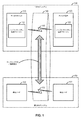
[0032]図1は、「1次(primary)」無線アクセス技術(RAT)システム100と「競合(competing)」RATシステム150とを含むものとして例として示されている、例示的なワイヤレスネットワーク環境を示すシステムレベル図である。各システムは、概して、様々なタイプの通信(たとえば、音声、データ、マルチメディアサービス、関連する制御シグナリングなど)に関係する情報を含む、ワイヤレスリンクを介して受信および/または送信することが可能な、異なるワイヤレスノードから構成され得る。1次RATシステム100は、ワイヤレスリンク130を介して互いに通信しているアクセスポイント110とアクセス端末120とを含むものとして示されている。競合RATシステム150は、別個のワイヤレスリンク132を介して互いに通信している2つの競合ノード152を含むものとして示されており、1つまたは複数のアクセスポイント、アクセス端末、または他のタイプのワイヤレスノードを同様に含み得る。一例として、1次RATシステム100のアクセスポイント110およびアクセス端末120は、ロングタームエボリューション(LTE)技術に従ってワイヤレスリンク130を介して通信し得、競合RATシステム150の競合ノード152は、Wi−Fi技術に従ってワイヤレスリンク132を介して通信し得る。各システムは、地理的領域全体にわたって分散された任意の数のワイヤレスノードをサポートし得、図示されたエンティティは単に説明の目的で示されていることが諒解されよう。
[0032] FIG. 1 is an exemplary wireless network environment shown as an example as including a "primary" wireless access technology (RAT) system 100 and a "competing"
[0033]別段に記載されていない限り、「アクセス端末」および「アクセスポイント」という用語は、特定のRATに固有のものでも、それに限定されるものでもない。概して、アクセス端末は、ユーザが通信ネットワークを介して通信することを可能にする任意のワイヤレス通信デバイス(たとえば、モバイルフォン、ルータ、パーソナルコンピュータ、サーバ、エンターテインメントデバイス、モノのインターネット(IOT:Internet of Things)/すべてのモノのインターネット(IOE:Internet of Everything)対応デバイス、車両内通信デバイスなど)であり得、代替的に、異なるRAT環境では、ユーザデバイス(UD)、移動局(MS)、加入者局(STA)、ユーザ機器(UE)などと呼ばれることがある。同様に、アクセスポイントは、アクセスポイントがそれにおいて展開されるネットワークに応じて、アクセス端末と通信している際に1つまたは複数のRATに従って動作し得、代替的に、基地局(BS)、ネットワークノード、ノードB、発展型ノードB(eNB)などと呼ばれることがある。そのようなアクセスポイントは、たとえば、スモールセルアクセスポイントに対応し得る。「スモールセル」は、概して、フェムトセル、ピコセル、マイクロセル、ワイヤレスローカルエリアネットワーク(WLAN)アクセスポイント、他の小さいカバレージエリアアクセスポイントなどを含むかまたは場合によってはそのように呼ばれることがある、低電力アクセスポイントのクラスを指す。スモールセルは、近傍内の数ブロックまたは地方環境における数平方マイルをカバーし得るマクロセルカバレージを補うために展開され得、それにより、改善されたシグナリング、漸進的キャパシティ増大、よりリッチなユーザエクスペリエンスなどにつながり得る。 [0033] Unless otherwise stated, the terms "access terminal" and "access point" are not specific to or limited to a particular RAT. In general, access terminals are any wireless communication device that allows users to communicate over a communication network (eg, mobile phones, routers, personal computers, servers, entertainment devices, the Internet of Things (IOT). ) / Internet of Everything (IOE) -enabled devices, in-vehicle communication devices, etc.), and instead, in different RAT environments, user devices (UD), mobile stations (MS), subscribers. It may be called a station (STA), a user device (UE), or the like. Similarly, the access point may operate according to one or more RATs while communicating with the access terminal, depending on the network in which the access point is deployed, and instead, the base station (BS),. It may be called a network node, a node B, an advanced node B (eNB), or the like. Such an access point may correspond to, for example, a small cell access point. "Small cells" generally include or are sometimes referred to as femtocells, picocells, microcells, wireless local area network (WLAN) access points, other small coverage area access points, etc., low. Refers to the class of power access points. Small cells can be deployed to supplement macro cell coverage that can cover a few blocks in the neighborhood or a few square miles in a rural environment, thereby improving signaling, gradual capacity increase, richer user experience, etc. Can lead to.
[0034]図1に戻ると、1次RATシステム100によって使用されるワイヤレスリンク130と、競合RATシステム150によって使用されるワイヤレスリンク132とは、共有通信媒体140を介して動作し得る。このタイプの通信媒体は、(たとえば、1つまたは複数のキャリアにわたる1つまたは複数のチャネルを包含する)1つまたは複数の周波数、時間、および/または空間通信リソースから構成され得る。一例として、通信媒体140は、無認可周波数帯域の少なくとも一部分に対応し得る。異なる認可周波数帯域が、(たとえば、米国における連邦通信委員会(FCC)などの政府機関によって)いくつかの通信のために予約済みであるが、いくつかのシステム、特に、スモールセルアクセスポイントを採用するものは、Wi−Fiを含むWLAN技術によって使用される無認可国内情報インフラストラクチャ(U−NII)帯域などの無認可周波数帯域に動作を拡張した。
Returning to FIG. 1, the
[0035]通信媒体140の共有により、ワイヤレスリンク130とワイヤレスリンク132との間のクロスリンク干渉(cross-link interference)の可能性がある。さらに、いくつかのRATおよびいくつかの管轄区域(jurisdiction)は、通信媒体140へのアクセスのために競合または「リッスンビフォアトーク(LBT)」を必要とし得る。一例として、クリアチャネルアセスメント(CCA)プロトコルが使用され得、それにおいて、各デバイスは、それ自体の送信のために通信媒体を奪取する(および、いくつかの場合には予約する)前に、媒体検知を介して共有通信媒体上の他のトラフィックの不在を確認する。いくつか設計では、CCAプロトコルは、通信媒体をRAT内トラフィックとRAT間トラフィックとにそれぞれ与えるための別個のCCAプリアンブル検出(CCA−PD:CCA Preamble Detection)機構とCCAエネルギー検出(CCA−ED:CCA Energy Detection)機構とを含み得る。欧州通信規格協会(ETSI)は、たとえば、無認可周波数帯域など、いくつかの通信媒体上の、それらのRATにかかわらずすべてのデバイスについての競合を規定する。
[0035] Due to the sharing of the
[0036]以下でより詳細に説明されるように、アクセスポイント110および/またはアクセス端末120は、上記で手短に説明された動的チャネル構成技法を与えるかまたはさもなければサポートするように、本明細書の教示に従ってさまざまに構成され得る。たとえば、アクセスポイント110はアップリンクチャネル構成マネージャ112を含み得、アクセス端末120はアップリンクチャネル構成マネージャ122を含み得る。アップリンクチャネル構成マネージャ112および/またはアップリンクチャネル構成マネージャ122は、通信媒体140上の異なるアップリンクチャネルの構成を管理するために異なる方法で構成され得る。
[0036] As described in more detail below, the
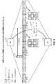
[0037]図2は、アクセスポイント110/アクセス端末120と競合RATシステム150との間での競合ベースアクセスを可能にするために、通信媒体140上に1次RATシステム100のためにインプリメントされ得る、例示的な仮想時分割複信(TDD)フレーム構造を示す。
FIG. 2 may be implemented for the primary RAT system 100 on the
[0038]図示されたフレーム構造は、システムフレーム番号ヌメロロジー(system frame number numerology)に従って番号付けされ(RF N、N+1、N+2など)、同じく参照のために番号付けされ得る(たとえば、SF0、SF1など)それぞれのサブフレーム(SF)に分割された、一連の無線フレーム(RF)を含む。各それぞれのサブフレームはさらにスロット(図2に図示せず)に分割され得、スロットはさらにシンボル期間に分割され得る。一例として、LTEフレーム構造は、10個のサブフレームからそれぞれ構成された1024個の番号付けされた無線フレームに分割されたシステムフレームを含み、それらはともに(たとえば、1msサブフレームを有する10ms無線フレームの場合、10.24秒持続する)システムフレームサイクルを構成する。その上、各サブフレームは2つのスロットを備え得、各スロットは6つまたは7つのシンボル期間を備え得る。フレーム構造の使用は、よりアドホックなシグナリング技法よりもデバイスの間のより自然で効率的な協調を与え得る。 [0038] The illustrated frame structures are numbered according to system frame number numerology (RF N, N + 1, N + 2, etc.) and can also be numbered for reference (eg, SF0, SF1, etc.). ) Includes a series of radio frames (RF) divided into each subframe (SF). Each respective subframe can be further subdivided into slots (not shown in FIG. 2), and the slots can be further subdivided into symbol periods. As an example, the LTE frame structure includes system frames divided into 1024 numbered radio frames, each composed of 10 subframes, both of which (eg, a 10 ms radio frame having a 1 ms subframe). In the case of, it constitutes a system frame cycle (lasting 10.24 seconds). Moreover, each subframe may have two slots, and each slot may have six or seven symbol periods. The use of frame structures can provide more natural and efficient coordination between devices than more ad hoc signaling techniques.
[0039]図2の例示的なフレーム構造は、各サブフレームが異なる時間にダウンリンク(D)、アップリンク(U)、またはスペシャル(S)サブフレームとしてさまざまに動作され得るという点で、TDDである。概して、ダウンリンクサブフレームは、ダウンリンク情報をアクセスポイント110からアクセス端末120に送信するために予約され、アップリンクサブフレームは、アップリンク情報をアクセス端末120からアクセスポイント110に送信するために予約され、スペシャルサブフレームは、ガード期間によって分離されたダウンリンク部分とアップリンク部分とを含み得る。ダウンリンク、アップリンク、およびスペシャルサブフレームの異なる配置は、異なるTDD構成と呼ばれることがある。上記のLTE例に戻ると、LTEフレーム構造のTDD変形態は、7つのTDD構成(TDD構成(Config)0〜TDD構成6)を含み、各構成は、ダウンリンク、アップリンク、およびスペシャルサブフレームの異なる配置を有する。たとえば、異なるトラフィックシナリオに適応するために、いくつかのTDD構成はより多くのダウンリンクサブフレームを有し得、いくつかはより多くのアップリンクサブフレームを有し得る。図2の図示の例では、LTEにおけるTDD構成3と同様であるTDD構成が採用される。採用された特定のTDD構成は、システム情報ブロック(SIB)メッセージ、制御領域中でTDDフレームフォーマットを示すための新しい物理チャネルなど(たとえば、LTEにおけるSIB−1メッセージ)を使用して、アクセスポイント110によってブロードキャストされ得る。
[0039] The exemplary frame structure of FIG. 2 is TDD in that each subframe can be operated differently as a downlink (D), uplink (U), or special (S) subframe at different times. Is. Generally, the downlink subframe is reserved for transmitting downlink information from the
[0040]各TDD構成は異なるが、すべてのTDD構成にわたって同じである、1つまたは複数のサブフレームがあり得る。これらのサブフレームは、本明細書ではアンカーサブフレーム(anchor subframe)と呼ばれる。再び上記のLTE例に戻ると、TDD構成TDD構成0〜TDD構成6の各々にわたる各無線フレームにおいて、サブフレームSF0はダウンリンクサブフレームであり、SF1はスペシャルサブフレームであり、SF2はアップリンクサブフレームであり、SF5はダウンリンクサブフレームである。図示の例では、アンカーサブフレームは、各無線フレームのサブフレームSF0、SF1、SF2、およびSF5に同様に対応するが、具体的なアンカーキャリア指定は、異なるシステムにわたって変動し得ることが諒解されよう。
[0040] Each TDD configuration may be different, but there may be one or more subframes that are the same across all TDD configurations. These subframes are referred to herein as anchor subframes. Returning to the above LTE example again, in each radio frame covering each of TDD configurations TDD configurations 0 to
[0041]図2の例示的なフレーム構造は、各サブフレームが、通信媒体140にアクセスするための競合プロシージャにより、所与のインスタンスにおける1次RATシグナリングによって占有されることがあるかまたは占有されないことがあるという点で、仮想である。概して、アクセスポイント110またはアクセス端末120が、所与のサブフレームについての競合に勝つことができない場合、そのサブフレームは無音化され得る。
[0041] In the exemplary frame structure of FIG. 2, each subframe may or may not be occupied by primary RAT signaling in a given instance by a competing procedure for accessing the
[0042]競合プロセス中のあるポイントにおいて、通信媒体140はクリアになり(たとえば、CCAクリア)、アクセスポイント110は、たとえば、それを奪取する。ある持続時間(たとえば、1つの無線フレーム)を有する送信機会(TXOP)のためにそれ自体のために通信媒体140を予約するために、アクセスポイント110は、競合RATシステム150のために定義されたチャネル予約メッセージ(RSV)202を送り得る。チャネル予約メッセージ202は、1次RAT動作のために通信媒体140を予約するために、通信媒体140を介して(たとえば、アクセスポイント110にも属する競合RAT固有トランシーバを介して)送信され得る。例示的なチャネル予約メッセージは、たとえば、競合Wi−Fi RATのための、802.11aデータパケット、自己への送信可(CTS2S:Clear-to-Send-to-Self)メッセージ、送信要求(RTS:Request-to-Send)メッセージ、送信可(CTS)メッセージ、物理レイヤコンバージェンスプロトコル(PLCP)ヘッダ(たとえば、レガシー信号(L−SIG)、高スループット信号(HT−SIG)、または超高スループット信号(VHT−SIG))など、または当該の他の競合RATのために定義された他の同様のメッセージを含み得る。チャネル予約メッセージ202は、アクセスポイント110がそれのためにアクセスを求めて競合した、ターゲットTXOPの持続時間に対応する持続時間指示(たとえば、ネットワーク割当てベクトル(NAV:Network Allocation Vector))を含み得る。
[0042] At some point during the competing process, the
[0043]通信媒体140上でのアップリンク動作を可能にするのを助けるために、アクセスポイント110は、物理アップリンク制御チャネル(PUCCH)として図2に示され、以下で例として説明される、アップリンク制御チャネルを静的にではなく動的に構成し得る。これは、競合RATシステム150によって作成される潜在的干渉またはチャネル阻止シナリオに応答して、フレキシビリティを与え得る。
[0043] To help enable uplink operation on the
[0044]図2にさらに示されているように、各アップリンクサブフレームは、通信媒体140上での時間(たとえば、所与のシンボル期間)リソースと周波数(たとえば、所与のサブキャリア)リソースとの異なる組合せに対応するいくつかのリソースエレメント204を含み得る。アクセスポイント110は、PUCCHを搬送するためのリソースのセットを動的に選択し得る。図示の例では、アクセスポイント110は、リソースエレメントの1つのセットを用いてPUCCHの第1のインスタンス(構成206)を構成し、リソースエレメントの別のセットを用いてPUCCHの第2のインスタンス(構成208)を構成し得る。
[0044] As further shown in FIG. 2, each uplink subframe is a time (eg, given symbol period) resource and a frequency (eg, given subcarrier) resource on the
[0045]アクセス端末シグナリングをPUCCH構成と協調させるために、アクセスポイント110は、たとえば、リソースエレメントの選択されたセットに関連する1つまたは複数の構成パラメータを含む構成メッセージ210を、アクセス端末120に送り得る。構成メッセージ210は、周期的に、またはイベント駆動ベースで送られ得る。例として、構成メッセージ210は、所与のTXOP中の各無線フレームの最初に送られ得る。
[0045] To coordinate access terminal signaling with the PUCCH configuration, the
[0046]図3は、構成メッセージ210の例示的なインプリメンテーションを示す。この例では、構成メッセージ210は、関連する部分において、所与のインプリメンテーションのについて適宜に、サブフレーム識別子302と、シンボル期間識別子304と、サブキャリア識別子306と、(1つまたは複数の)他の識別子308とを含む。単一の構成メッセージ210は、単に説明の目的で示されており、異なる設計およびシナリオでは、様々な識別子が、信号の異なるセット中で、別個の個々の信号としてなど送信(ブロードキャストまたはユニキャスト)され得るか、または適宜に完全に省略され得ることが諒解されよう。
[0046] FIG. 3 shows an exemplary implementation of
[0047]サブフレーム識別子302は、リソースエレメントの選択されたセットが位置する1つまたは複数のアップリンクサブフレームを識別するために使用され得る。たとえば、再び図2を参照すると、サブフレーム識別子302は、第1の構成206に関連するアップリンクサブフレーム、第2の構成208に関連するアップリンクサブフレーム、またはその両方を識別し得る。概して、識別されたアップリンクサブフレームは、構成メッセージ210がその中で送られるTXOP(たとえば、第1の構成206に関連するアップリンクサブフレーム)内にあるか、または構成メッセージ210がその中で送られるTXOP(たとえば、第2の構成208に関連するアップリンクサブフレーム)外にあり得る。
[0047] The
[0048]シンボル期間識別子304は、リソースエレメントの選択されたセットが位置する1つまたは複数のシンボル期間を識別し得る。たとえば、シンボル期間識別子304は、サブフレーム識別子302によって識別されるアップリンクサブフレーム内のPUCCHのための開始位置および持続時間を識別し得る。いくつかの設計では、開始位置または持続時間のみが明示的に識別され、もう一方が(たとえば、割り当てられたPUCCHフォーマットに基づいて)暗示されるかまたはさもなければあらかじめ決定され得る。シンボル期間の数は、(たとえば、異なるサイズのペイロードのための短いPUCCHフォーマットと、より長いPUCCHフォーマットの両方をカバーするために、2つ、7つ、または14個のシンボル期間にわたる)フレキシブル動作を可能にするように動的に構成され得る。シンボル期間はまた、基準シンボル期間とペイロードシンボル期間の両方を含み得る(たとえば、2つのシンボル期間にわたるPUCCHの場合、第1のシンボル期間は基準シンボルのために使用され得、第2のシンボル期間はPUCCHペイロードを搬送し得る)。
[0048] The
[0049]サブキャリア識別子306は、リソースエレメントの選択されたセットが位置する1つまたは複数のサブキャリアを識別し得る。たとえば、サブキャリア識別子306は、シンボル期間識別子304によって識別されるシンボル期間内にPUCCHを搬送する特定の1つまたは複数の周波数を識別し得る。別の例として、サブキャリア識別子306は、シンボル期間識別子304によって識別されるシンボル期間内にPUCCHを搬送するチャネル帯域幅にわたる周波数のインターレースを識別し得る。
The
[0050]構成メッセージ210は、個々のアクセス端末を対象とするユニキャストシグナリングとアクセス端末のグループに共通のブロードキャスト/マルチキャストシグナリングの両方を含む、様々な方法で送られ得る。たとえば、構成メッセージ210は、個々の無線リソース制御(RRC)メッセージとして別々に各アクセス端末に送られ得る。別の例として、構成メッセージ210は、共通ダウンリンク制御情報(DCI)メッセージとしてまとめて各アクセス端末に送られ得る。どのアクセス端末がそれの構成とともにPUCCH上での送信のために指定されるかを示す新しいDCIフォーマットが定義され得る。DCIフォーマットは、共通メッセージ中で1つまたは複数のアクセス端末のための情報を伝達するために使用され得る。
[0050]
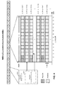
[0051]図4は、関連する部分において、PUCCHなどのアップリンク制御チャネルを、例として物理アップリンク共有チャネル(PUSCH:Physical Uplink Shared Channel)として示されているアップリンクデータチャネルと多重化するための例示的なサブフレーム構造を示すリソースマップである。概して、PUSCHは、時間領域においてサブフレームを構成するシンボル期間(たとえば、ノーマルサイクリックプレフィックスの場合は14個のシンボル期間)の全部または一部分にわたり、周波数領域においてサブキャリアのセットから形成される1つまたは複数のサブキャリアインターレースにわたり得る。 [0051] FIG. 4 is for multiplexing an uplink control channel, such as a PUCCH, with an uplink data channel, for example, shown as a Physical Uplink Shared Channel (PUSCH) in a relevant portion. It is a resource map showing an exemplary subframe structure of. In general, a PUSCH is one formed from a set of subcarriers in the frequency domain over all or part of the symbolic periods that make up the subframe in the time domain (eg, 14 symbol periods in the case of a normal cyclic prefix). Or get over multiple subcarrier interlaces.
[0052]図示の例では、サブフレームを構成するリソースエレメントは、様々なリソースブロック(RB)にグループ化され、(インターレース#1〜#10として示されている)10個のインターレースに分離され、PUCCHおよびPUSCHは、RBおよびインターレースのそれぞれのサブセットを占有する。インターレーシング構造の例として、100個のRBをもつ20MHzチャネル帯域幅の場合、10個ごとのRBからなる10個のRBのセットが、各インターレースに専用であり得る。物理的ランダムアクセスチャネル(PRACH:Physical Random Access Channel)、サウンディング基準信号(SRS:Sounding Reference Signal)チャネルなどの他のチャネル(図示せず)が、他のRBおよびインターレースを占有し得る。
In the illustrated example, the resource elements that make up the subframe are grouped into various resource blocks (RBs) and separated into 10 interlaces (indicated as
[0053]アクセスポイント110は、先行するサブフレーム中の許可メッセージ410などを介してPUSCHのためのリソースエレメントのサブセットをアクセス端末120に割り当てることができる。しかしながら、図示のように、PUSCHは、対応するインターレースが動的に割り当てられたPUCCH(または何らかの他のチャネル)によって共有されるかどうかに応じて、異なるシンボル期間中に開始し得る。図示の例では、PUSCHは、PUCCHが第1および第2のシンボル期間を占有するインターレース#1では第3のシンボル期間において開始するが、PUCCHを含んでいないインターレース#2では第1のシンボル期間において開始し得る。
[0053] The
[0054]アクセス端末120が所与のインターレース中のPUSCHのロケーションを識別することを支援するために、許可メッセージ410は、PUSCHを搬送するリソースエレメントのセットのためのサブフレーム内の開始時間(たとえば、シンボル期間)を識別する1つまたは複数のPUSCHタイミングパラメータ412をさらに含み得る。上記の例に戻ると、タイミングパラメータ412は、インターレース#1中のPUSCHのための開始時間としてそのインターレース中の第3のシンボル期間を識別し、インターレース#2中のPUSCHのための開始時間としてそのインターレース中の第1のシンボル期間を識別し得、以下同様である。この情報に基づいて、アクセス端末120は、それに応じて、レートマッチングをも実施し得る。
[0054] To help the
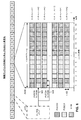
[0055]図5は、関連する部分において、PUCCHなどのアップリンク制御チャネルをPUSCHなどのアップリンクデータチャネルと多重化するための別の例示的なサブフレーム構造を示すリソースマップである。この例では、各インターレースの最初の2つのシンボル期間はPUCCHのために構成され、第1のアクセス端末(AT−1)に割当てられるが、各インターレースの残りのシンボル期間はPUSCHのために構成され、例としてアクセス端末120として示されている第2のアクセス端末(AT−2)に少なくとも部分的に割り当てられる。このシナリオは、たとえば、アクセス端末が、同じサブフレーム中のPUCCHとPUSCHの両方の上で送信するのを制限されるいくつかのシステムにおいて起こり得る。
[0055] FIG. 5 is a resource map showing another exemplary subframe structure for multiplexing an uplink control channel, such as PUCCH, with an uplink data channel, such as PUSCH, in a relevant portion. In this example, the first two symbol periods of each interlace are configured for PUCCH and are assigned to the first access terminal (AT-1), while the remaining symbol periods of each interlace are configured for PUSCH. , As an example, assigned at least partially to a second access terminal (AT-2), which is shown as
[0056]図示のように、別個の割当ておよび潜在的サブフレーム制限にもかかわらず、アクセス端末120は、最初の2つのシンボル期間中にPUCCHを介してシグナリングを送り得る。いくつかの展開では、通信媒体140のための競合要件は、アクセスを求めて再競合しなければならないことを回避するために連続占有を要求し得る。最初の2つのシンボル期間中にPUCCHを介してシグナリングを送ることによって、アクセス端末120は、PUSCHに至る必要とされる送信連続性を維持し、通信媒体140へのアクセスを求めて再競合しなければならないことを回避し得る。再競合は、他のアクセス端末(AT−1)がPUSCHの直前に媒体140を占有することにより、困難であり得る。
[0056] As shown, the
[0057]ダミー信号502などが、最初の2つのシンボル期間中にアクセス端末120によって使用され得る。一例として、ダミー信号502は、ダミー信号502を他のアクセス端末(AT−1)によるPUCCHシグナリングと区別するために、アクセス端末120に関連し、アクセスポイント110に知られているシグネチャを有し得る。シグネチャは、ダミー信号の一部として送られる基準信号のために使用される拡散シーケンスの形態であり得る。別の例として、ダミー信号502は、同じくダミー信号502を他のアクセス端末(AT−1)によるPUCCHシグナリングと区別するために、ダミーシグナリングのために予約された1つまたは複数の所定のインターレースを占有し得る。実際のPUSCHデータ信号504は、次の指定されたシンボル期間中にアクセス端末120によって送信され得る。
[0057] A
[0058]図6は、関連する部分において、PUCCHなどのアップリンク制御チャネルをPUSCHなどのアップリンクデータチャネルと多重化するための電力制御方式を示すリソースマップである。この例では、いくつかのインターレース(たとえば、奇数番号のインターレース#1、#3など)の最初の2つのシンボル期間は、PUCCHを搬送するように構成され、他のシンボル期間および他のインターレースは、図示のようにPUSCHまたは他のチャネルを搬送するように構成される。図示されたサブフレームの第1のシンボル期間中に、PUCCHとPUSCHとはサブキャリアインターレースにわたって多重化される。図示されたサブフレームの第2のシンボル期間中に、PUCCHとPUSCHとは多重化されない。
[0058] FIG. 6 is a resource map showing a power control method for multiplexing an uplink control channel such as PUCCH with an uplink data channel such as PUSCH in a related portion. In this example, the first two symbol periods of some interlaces (eg, odd-numbered
[0059]図示のように、アクセスポイント110は2つのチャネルのための送信電力を設定し、PUCCHとPUSCHとを搬送するアップリンクサブフレームより前の先行するダウンリンクサブフレーム中になど、アクセス端末120ならびにサービスされている他のアクセス端末に、対応する電力制御コマンド610を送信し得る。電力制御コマンド610は、直接または間接的にのいずれかで、PUCCHとPUSCHの一方または両方のための送信電力を示し得、別個のPUSCH送信電力602およびPUCCH送信電力604が、説明の目的で示されている。一例として、電力制御コマンド610は、チャネルの一方または両方のための設定点(a set-point)、チャネル間のオフセットなどを含み得る。
As shown, the
[0060]さらに示されているように、PUCCH送信電力は、PUSCH送信電力とは無関係ではなく、PUSCH送信電力に基づいて設定され得る。たとえば、PUCCHは、概してより低い送信電力を必要とするが、PUSCH送信電力に一致するかまたは実質的に一致するように送信電力をブーストすることは有益であり得る。2つのチャネルにわたるより均一な送信電力は、より緩和しやすいより均一な干渉パターンを生じ得、アクセスポイント110とアクセス端末120の両方におけるより簡単なインプリメンテーションをも可能にし得る。PUCCHがPUSCHなしに送信される図示の例の第2のシンボル期間の場合のように、PUCCHとPUSCHとが同じシンボル期間中に送信されないときでも、PUCCH送信電力をブーストすることは、通信媒体140が、アクセスポイント110の完全なカバレージエリア上で1次RATシステム100によって占有されたままであることを可能にし、したがって、競合RATシステム150が通信媒体140の一部分を奪取するのを防ぎ得る。
[0060] As further indicated, the PUCCH transmit power is not independent of the PUSCH transmit power and can be set based on the PUSCH transmit power. For example, PUCCH generally requires lower transmit power, but it can be beneficial to boost transmit power to match or substantially match PUSCH transmit power. More uniform transmit power across the two channels can result in more uniform interference patterns that are easier to mitigate and can also allow easier implementation at both the
[0061]概して、PUCCHおよびPUSCHは、すべてのシンボル期間およびサブキャリアにわたって一定の電力を用いて送信され得る。送信電力はまた、各チャネルのカバレージエリアを少なくとも総電力制約内で最大にし、さらに、1次RATシステム100による通信媒体140へのアクセスを保持するために選定され得る。また、PUCCHおよびPUSCHはここでは説明の目的で説明されるが、サウンディング基準信号(SRS)チャネル、チャネル状態情報基準信号(CSI−RS)チャネルなどの他の制御チャネルを含む、他のチャネルのための電力制御は、それらのカバレージエリアに一致するかまたは実質的に一致するように同様の様式で実施され得ることが諒解されよう。
[0061] In general, PUCCH and PUSCH can be transmitted with constant power over all symbol periods and subcarriers. The transmit power may also be selected to maximize the coverage area of each channel, at least within the total power constraint, and to retain access to the
[0062]図7は、上記で説明された技法による、通信の例示的な方法を示す流れ図である。方法700は、たとえば、共有通信媒体上で動作するアクセスポイント(たとえば、図1に示されているアクセスポイント110)によって実施され得る。一例として、通信媒体は、LTE技術デバイスとWi−Fi技術デバイスとの間で共有される無認可無線周波数帯域上の1つまたは複数の時間、周波数、または空間リソースを含み得る。
[0062] FIG. 7 is a flow diagram illustrating an exemplary method of communication by the technique described above.
[0063]図示のように、アクセスポイントは、アップリンク制御チャネルを搬送するためのリソースエレメントのセットを選択し(ブロック702)、リソースエレメントの選択されたセットに関連する1つまたは複数の構成パラメータを含む構成メッセージを1つまたは複数のアクセス端末に送信する(ブロック704)。アクセスポイントは、次いで、リソースエレメントの選択されたセットを介して1つまたは複数のアクセス端末からアップリンク制御シグナリングを受信する(ブロック706)。 [0063] As shown, the access point selects a set of resource elements to carry the uplink control channel (block 702) and one or more configuration parameters associated with the selected set of resource elements. A configuration message containing the above is sent to one or more access terminals (block 704). The access point then receives uplink control signaling from one or more access terminals via a selected set of resource elements (block 706).
[0064]上記でより詳細に説明されたように、アクセスポイントはまた、アップリンク制御チャネルの構成を動的に変化させ得る。たとえば、アクセスポイントは、アップリンク制御チャネルを搬送するためのリソースエレメントの他のセットを選択し、リソースエレメントの他の選択されたセットに関連する1つまたは複数の他の構成パラメータを含む他の構成メッセージを1つまたは複数のアクセス端末に送信し、リソースエレメントの他の選択されたセットを介して1つまたは複数のアクセス端末からアップリンク制御シグナリングを受信し得る。 [0064] As described in more detail above, the access point can also dynamically change the configuration of the uplink control channel. For example, the access point selects another set of resource elements to carry the uplink control channel and contains one or more other configuration parameters associated with the other selected set of resource elements. Configuration messages may be sent to one or more access terminals and uplink control signaling may be received from one or more access terminals via another selected set of resource elements.
[0065]一例として、1つまたは複数の構成パラメータは、リソースエレメントの選択されたセットが位置する1つまたは複数のアップリンクサブフレームを識別するサブフレーム識別子、リソースエレメントの選択されたセットが位置する1つまたは複数のシンボル期間を識別するシンボル期間識別子、リソースエレメントの選択されたセットが位置する1つまたは複数のサブキャリアを識別するサブキャリア識別子、またはそれらの組合せを含み得る。 [0065] As an example, one or more configuration parameters are subframe identifiers that identify one or more uplink subframes where the selected set of resource elements is located, the location of the selected set of resource elements. It may include a symbol period identifier that identifies one or more symbol periods, a subcarrier identifier that identifies one or more subcarriers in which a selected set of resource elements is located, or a combination thereof.
[0066]構成メッセージは、異なる方法で送信され得る(ブロック704)。たとえば、構成メッセージは、個々のRRCメッセージとして別々に1つまたは複数のアクセス端末の各々に送信され得る。別の例として、構成メッセージは、共通DCIメッセージとしてまとめて1つまたは複数のアクセス端末の各々に送信され得る。 [0066] The configuration message may be transmitted in different ways (block 704). For example, the configuration message may be sent separately to each of one or more access terminals as individual RRC messages. As another example, the configuration message may be collectively transmitted as a common DCI message to each of one or more access terminals.
[0067]いくつかの設計またはシナリオでは、アクセスポイントはまた、アップリンクデータチャネルを構成し得る。たとえば、アクセスポイントは、アップリンクデータチャネルを搬送するためのリソースエレメントの他のセットを選択し、アップリンクデータチャネルを搬送するリソースエレメントの選択されたセットは、アップリンク制御チャネルを搬送するリソースエレメントの選択されたセットと共通サブフレーム中で多重化される(随意のブロック708)。アクセスポイントは、次いで、アップリンクデータチャネルを搬送するリソースエレメントの選択されたセットのためのサブフレーム内の開始時間を識別する許可メッセージを1つまたは複数のアクセス端末に送信し(随意のブロック710)、アップリンクデータチャネルを搬送するリソースエレメントの選択されたセットを介して、1つまたは複数のアクセス端末からアップリンクデータシグナリングを受信する(随意のブロック712)。許可メッセージは、たとえば、アップリンクデータチャネルを搬送するリソースエレメントの選択されたセットの第1のサブキャリアインターレースのための第1の開始時間と、アップリンクデータチャネルを搬送するリソースエレメントの選択されたセットの第2のサブキャリアインターレースのための第2の開始時間とを識別し得る。 [0067] In some designs or scenarios, the access point may also configure an uplink data channel. For example, the access point selects another set of resource elements to carry the uplink data channel, and the selected set of resource elements to carry the uplink data channel is the resource element to carry the uplink control channel. Multiplexed in a common subframe with the selected set of (optional block 708). The access point then sends a permission message identifying the start time within the subframe for the selected set of resource elements carrying the uplink data channel to one or more access terminals (optional block 710). ), Receive uplink data signaling from one or more access terminals via a selected set of resource elements that carry the uplink data channel (optional block 712). The authorization message is, for example, the first start time for the first subcarrier interlace of the selected set of resource elements that carry the uplink data channel, and the selection of the resource element that carries the uplink data channel. It can be distinguished from the second start time for the second subcarrier interlace of the set.
[0068]いくつかの設計またはシナリオでは、アクセス端末が所与のシンボル期間中に制御シグナリングのために指定されない場合でも、アクセスポイントは、そのシンボル期間中にアクセス端末からアップリンク制御シグナリングを受信し得る。たとえば、アクセスポイントは、第1のシンボル期間中に、アップリンク制御チャネルを搬送するリソースエレメントの選択されたセットの少なくとも一部分を、第1のアクセス端末に割り当て、第2のシンボル期間中に、アップリンクデータチャネルを搬送するリソースエレメントの選択されたセットの少なくとも一部分を、第2のアクセス端末に割り当てることができる。アクセスポイントは、次いで、第1のシンボル期間の間に、アップリンク制御チャネルを搬送するリソースエレメントの選択されたセットの割り当てられた部分を介して、第2のアクセス端末からシグナリングを受信し得る。一例として、受信されたシグナリングは、第2のアクセス端末に関連するシグネチャを有するか、またはダミーシグナリングのために予約されたサブキャリアインターレース上で受信された、ダミー信号を備え得る。 [0068] In some designs or scenarios, the access point receives uplink control signaling from the access terminal during that symbol period, even if the access terminal is not specified for control signaling during that symbol period. obtain. For example, the access point allocates at least a portion of a selected set of resource elements carrying the uplink control channel to the first access terminal during the first symbol period and is up during the second symbol period. At least a portion of a selected set of resource elements carrying a linked data channel can be assigned to a second access terminal. The access point may then receive signaling from the second access terminal via an assigned portion of a selected set of resource elements carrying the uplink control channel during the first symbol period. As an example, the signal received may comprise a dummy signal having a signature associated with a second access terminal or received on a subcarrier interlace reserved for dummy signaling.
[0069]いくつかの設計またはシナリオでは、アクセスポイントは、(たとえば、カバレージエリアに一致するかまたは実質的に一致するように)アップリンク制御チャネルの送信電力をアップリンクデータチャネルの送信電力に結合し得る。たとえば、アクセスポイントは、アップリンクデータチャネルのための第1の送信電力を設定し、アップリンクデータチャネルのための第1の送信電力に基づいて、アップリンク制御チャネルのための第2の送信電力を設定し、アップリンク制御チャネルのための少なくとも第2の送信電力を示す電力制御コマンドを1つまたは複数のアクセス端末に送信し得る。 [0069] In some designs or scenarios, the access point combines the transmit power of the uplink control channel with the transmit power of the uplink data channel (for example, to match or substantially match the coverage area). Can be done. For example, the access point sets a first transmit power for the uplink data channel and a second transmit power for the uplink control channel based on the first transmit power for the uplink data channel. Can be set to send a power control command indicating at least a second transmit power for the uplink control channel to one or more access terminals.
[0070]図8は、上記で説明された技法による、通信の別の例示的な方法を示す流れ図である。方法800は、たとえば、共有通信媒体上で動作するアクセス端末(たとえば、図1に示されているアクセス端末120)によって実施され得る。一例として、通信媒体は、LTE技術デバイスとWi−Fi技術デバイスとの間で共有される無認可無線周波数帯域上の1つまたは複数の時間、周波数、または空間リソースを含み得る。
[0070] FIG. 8 is a flow diagram illustrating another exemplary method of communication, according to the techniques described above.
[0071]図示のように、アクセス端末は、アクセスポイントから、アップリンク制御チャネルのための1つまたは複数の構成パラメータを含む構成メッセージを受信し(ブロック802)、構成メッセージに基づいて、アップリンク制御チャネルを搬送するように構成されたリソースエレメントのセットを決定する(ブロック804)。アクセス端末は、次いで、リソースエレメントの決定されたセットを介してアクセスポイントにアップリンク制御シグナリングを送信する(ブロック806)。 [0071] As shown, the access terminal receives from the access point a configuration message containing one or more configuration parameters for the uplink control channel (block 802), and based on the configuration message, uplinks. Determine the set of resource elements configured to carry the control channel (block 804). The access terminal then sends uplink control signaling to the access point via a determined set of resource elements (block 806).
[0072]上記でより詳細に説明されたように、アクセス端末はまた、アップリンク制御チャネルの構成が変化したと動的に決定し得る。たとえば、アクセス端末は、アクセスポイントから、アップリンク制御チャネルのための1つまたは複数の他の構成パラメータを含む他の構成メッセージを受信し、他の構成メッセージに基づいて、アップリンク制御チャネルを搬送するように構成されたリソースエレメントの他のセットを決定し、リソースエレメントの他の決定されたセットを介してアクセスポイントにアップリンク制御シグナリングを送信し得る。 As described in more detail above, the access terminal may also dynamically determine that the configuration of the uplink control channel has changed. For example, an access terminal receives from an access point another configuration message containing one or more other configuration parameters for the uplink control channel and carries the uplink control channel based on the other configuration message. It may determine another set of resource elements configured to do so and send uplink control signaling to the access point through the other determined set of resource elements.
[0073]一例として、1つまたは複数の構成パラメータは、リソースエレメントの決定されたセットが位置する1つまたは複数のアップリンクサブフレームを識別するサブフレーム識別子、リソースエレメントの決定されたセットが位置する1つまたは複数のシンボル期間を識別するシンボル期間識別子、リソースエレメントの決定されたセットが位置する1つまたは複数のサブキャリアを識別するサブキャリア識別子、またはそれらの組合せを含み得る。 [0073] As an example, one or more configuration parameters are subframe identifiers that identify one or more uplink subframes where a determined set of resource elements is located, where a determined set of resource elements is located. It may include a symbol period identifier that identifies one or more symbol periods, a subcarrier identifier that identifies one or more subcarriers in which a determined set of resource elements is located, or a combination thereof.
[0074]構成メッセージは、異なる方法で受信され得る(ブロック802)。たとえば、構成メッセージは、アクセスポイントから個々のRRCメッセージとして受信され得る。別の例として、構成メッセージは、アクセスポイントから共通DCIメッセージとして受信され得る。 [0074] Configuration messages can be received in different ways (block 802). For example, configuration messages can be received from access points as individual RRC messages. As another example, the configuration message may be received from the access point as a common DCI message.
[0075]いくつかの設計またはシナリオでは、アクセス端末はまた、アップリンクデータチャネルの構成を決定し得る。たとえば、アクセス端末は、アクセスポイントから、アップリンクデータチャネルのためのサブフレーム内の開始時間を識別する許可メッセージを受信し(随意のブロック808)、許可メッセージに基づいて、アップリンクデータチャネルを搬送するように構成されたリソースエレメントの他のセットを決定し、アップリンクデータチャネルを搬送するリソースエレメントの決定されたセットが、アップリンク制御チャネルを搬送するリソースエレメントの決定されたセットとサブフレーム中で多重化される(随意のブロック810)。アクセス端末は、次いで、アップリンクデータチャネルを搬送するリソースエレメントの決定されたセットを介してアクセスポイントにアップリンクデータシグナリングを送信する(随意のブロック812)。許可メッセージは、たとえば、アップリンクデータチャネルを搬送するリソースエレメントの決定されたセットの第1のサブキャリアインターレースのための第1の開始時間と、アップリンクデータチャネルを搬送するリソースエレメントの決定されたセットの第2のサブキャリアインターレースのための第2の開始時間とを識別し得る。 [0075] In some designs or scenarios, the access terminal may also determine the configuration of the uplink data channel. For example, the access terminal receives an authorization message from the access point that identifies the start time in the subframe for the uplink data channel (optional block 808) and carries the uplink data channel based on the authorization message. Determines the other set of resource elements that are configured to, and the determined set of resource elements that carry the uplink data channel is in the subframe with the determined set of resource elements that carry the uplink control channel. It is multiplexed with (optional block 810). The access terminal then sends uplink data signaling to the access point via a determined set of resource elements that carry the uplink data channel (optional block 812). The authorization message was determined, for example, the first start time for the first subcarrier interlace of the determined set of resource elements to carry the uplink data channel and the resource element to carry the uplink data channel. It can be distinguished from the second start time for the second subcarrier interlace of the set.
[0076]いくつかの設計またはシナリオでは、アクセス端末が所与のシンボル期間中に制御シグナリングのために指定されない場合でも、アクセス端末は、そのシンボル期間中にアップリンク制御シグナリングを送信し得る。たとえば、アクセス端末は、アクセスポイントから、第1のシンボル期間中に、アップリンク制御チャネルを搬送するリソースエレメントの決定されたセットのいずれの割当ても受信しないが、アクセスポイントから、第2のシンボル期間中に、アップリンクデータチャネルを搬送するリソースエレメントの決定されたセットの少なくとも一部分の割当てを受信し得る。それにもかかわらず、アクセス端末は、第1のシンボル期間の間に、アップリンク制御チャネルを搬送するリソースエレメントの決定されたセットの割り当てられた部分を介して、アクセスポイントにシグナリングを送信し得る。一例として、送信されたシグナリングは、シグナリングを送信するアクセス端末に関連するシグネチャを有するか、またはダミーシグナリングのために予約されたサブキャリアインターレース上で送信された、ダミー信号を備え得る。 [0076] In some designs or scenarios, an access terminal may transmit uplink control signaling during that symbol period, even if the access terminal is not designated for control signaling during that symbol period. For example, the access terminal does not receive any allocation of a determined set of resource elements carrying the uplink control channel from the access point during the first symbol period, but from the access point during the second symbol period. In, an allocation of at least a portion of a determined set of resource elements carrying an uplink data channel may be received. Nevertheless, the access terminal may transmit signaling to the access point via an assigned portion of a determined set of resource elements carrying the uplink control channel during the first symbol period. As an example, the transmitted signaling may comprise a dummy signal having a signature associated with the access terminal transmitting the signaling or transmitted over a subcarrier interlace reserved for dummy signaling.
[0077]いくつかの設計またはシナリオでは、アクセス端末は、(たとえば、カバレージエリアに一致するかまたは実質的に一致するように)アップリンク制御チャネルの送信電力をアップリンクデータチャネルの送信電力に結合し得る。たとえば、アクセス端末は、アクセスポイントから電力制御コマンドを受信し、電力制御コマンドに基づいて第1の送信電力においてアップリンクデータチャネルを介してアップリンクデータシグナリングを送信し、電力制御コマンドと第1の送信電力とに基づいて第2の送信電力においてアップリンク制御チャネルを介してアップリンク制御シグナリングを送信し得る。 [0077] In some designs or scenarios, the access terminal combines the transmit power of the uplink control channel with the transmit power of the uplink data channel (eg, to match or substantially match the coverage area). Can be done. For example, the access terminal receives a power control command from the access point and, based on the power control command, transmits uplink data signaling over the uplink data channel at the first transmit power, with the power control command and the first. Uplink control signaling may be transmitted over the uplink control channel at the second transmit power based on the transmit power.
[0078]一般性のために、アクセスポイント110およびアクセス端末120は、図1では、それぞれ、アップリンクチャネル構成マネージャ112およびアップリンクチャネル構成マネージャ122を含むものとして関連する部分においてのみ示されている。しかしながら、アクセスポイント110およびアクセス端末120は、本明細書で説明される動的チャネル構成技法を与えるかまたはさもなければサポートするように様々な方法で構成され得ることが諒解されよう。
[0078] For generality, the
[0079]図9は、1次RATシステム100のアクセスポイント110およびアクセス端末120の例示的な構成要素をより詳細に示すデバイスレベル図である。図示のように、アクセスポイント110およびアクセス端末120はそれぞれ、概して、少なくとも1つの指定されたRATを介して他のワイヤレスノードと通信するための(通信デバイス930および950によって表される)ワイヤレス通信デバイスを含み得る。通信デバイス930および950は、指定されたRATに従って信号(たとえば、メッセージ、指示、情報、パイロットなど)を送信および符号化するため、および逆に、信号を受信および復号するためにさまざまに構成され得る。
[0079] FIG. 9 is a device level diagram showing in more detail exemplary components of the
[0080]通信デバイス930および950は、たとえば、それぞれの1次RATトランシーバ932および952、ならびに、いくつかの設計では、それぞれ、(たとえば、競合RATシステム150によって採用されるRATに対応する)(随意の)コロケートされた2次RATトランシーバ934および954など、1つまたは複数のトランシーバを含み得る。本明細書で使用される「トランシーバ」は、送信機回路、受信機回路、またはそれらの組合せを含み得るが、すべての設計において送信機能と受信機能の両方を与える必要があるとは限らない。たとえば、完全な通信を与えることが必要でないとき、コストを低減するために、いくつかの設計では、低機能受信機回路が採用され得る(たとえば、低レベルスニッフィングのみを与える無線チップまたは同様の回路)。さらに、本明細書で使用される「コロケートされた(co-located)」(たとえば、無線機、アクセスポイント、トランシーバなど)という用語は、様々な配置のうちの1つを指し得る。たとえば、同じハウジング中にある構成要素、同じプロセッサによってホストされる構成要素、互いの定義された距離内にある構成要素、および/またはインターフェース(たとえば、イーサネット(登録商標)スイッチ)を介して接続された構成要素、ここで、インターフェースは、必要とされるコンポーネント間通信(たとえば、メッセージング)のレイテンシ要件を満たす。
[0080] The
[0081]アクセスポイント110およびアクセス端末120はそれぞれ、概して、それらのそれぞれの通信デバイス930および950の動作(たとえば、指示すること、変更すること、有効にすること、無効にすることなど)を制御するための(通信コントローラ940および960によって表される)通信コントローラをも含み得る。通信コントローラ940および960は、それぞれ、1つまたは複数のプロセッサ942および962、ならびにプロセッサ942および962に結合された1つまたは複数のメモリ944および964を含み得る。メモリ944および964は、オンボードキャッシュメモリとして、別個の構成要素として、組合せとしてなどのいずれかで、データ、命令、またはそれらの組合せを記憶するように構成され得る。プロセッサ942および962ならびにメモリ944および964は、スタンドアロン通信構成要素であり得るか、またはアクセスポイント110およびアクセス端末120のそれぞれのホストシステム機能の一部であり得る。
[0081] The
[0082]アップリンクチャネル構成マネージャ112とアップリンクチャネル構成マネージャ122とは、異なる方法でインプリメントされ得ることが諒解されよう。いくつかの設計では、それに関連する機能の一部または全部が、少なくとも1つのプロセッサ(たとえば、プロセッサ942のうちの1つまたは複数および/またはプロセッサ962のうちの1つまたは複数)、少なくとも1つのメモリ(たとえば、メモリ944のうちの1つまたは複数および/またはメモリ964のうちの1つまたは複数)、(たとえば、トランシーバ932および934の1つまたは複数ならびに/またはトランシーバ952および954の1つまたは複数)、あるいはそれらの組合せによってインプリメントされるか、またはさもなければそれらの指示においてインプリメントされ得る。他の設計では、それに関連する機能の一部または全部が、一連の相互に関係する機能モジュールとしてインプリメントされ得る。
It will be appreciated that the uplink
[0083]したがって、図1〜図8に関して上記で説明された動作を実施するために図9中の構成要素が使用され得ることが諒解されよう。たとえば、アクセスポイント110は、プロセッサ942とメモリ944とを介して、アップリンク制御チャネルを搬送するためのリソースエレメントのセットを選択し得る。アクセスポイント110は、1次RATトランシーバ932を介して、リソースエレメントの選択されたセットに関連する1つまたは複数の構成パラメータを含む構成メッセージをアクセス端末120に送信し得る。アクセスポイント110は、1次RATトランシーバ932を介して、アクセス端末120から、リソースエレメントの選択されたセットを介してアップリンク制御シグナリングを受信し得る。さらに、アクセスポイント110は、プロセッサ942とメモリ944とを介して、アップリンクデータチャネルを搬送するためのリソースエレメントの他のセットを選択し得る。アクセスポイント110は、次いで、1次RATトランシーバ932を介して、アップリンクデータチャネルを搬送するリソースエレメントの選択されたセットのためのサブフレーム内の開始時間を識別する許可メッセージをアクセス端末120に送信し得る。アクセスポイント110は、1次RATトランシーバ932を介して、アップリンクデータチャネルを搬送するリソースエレメントの選択されたセットを介して、アクセス端末120からアップリンクデータシグナリングを受信し得る。
It will therefore be appreciated that the components in FIG. 9 can be used to perform the operations described above with respect to FIGS. 1-8. For example,
[0084]別の例として、アクセス端末120は、プロセッサ962とメモリ964とを介して、アクセスポイント110から、アップリンク制御チャネルのための1つまたは複数の構成パラメータを含む構成メッセージを受信し得る。アクセス端末120は、プロセッサ962とメモリ964とを介して、構成メッセージに基づいて、アップリンク制御チャネルを搬送するように構成されたリソースエレメントのセットを決定し得る。アクセス端末120は、次いで、1次RATトランシーバ952を介して、リソースエレメントの決定されたセットを介してアクセスポイント110にアップリンク制御シグナリングを送信し得る。さらに、アクセス端末は、1次RATトランシーバ952を介して、アクセスポイント110から、アップリンクデータチャネルのためのサブフレーム内の開始時間を識別する許可メッセージを受信し得る。アクセス端末120は、プロセッサ962およびメモリ964を介して、許可メッセージに基づいて、アップリンクデータチャネルを搬送するように構成されたリソースエレメントの他のセットを決定し得る。アクセス端末120は、次いで、1次RATトランシーバ952を介して、アップリンクデータチャネルを搬送するリソースエレメントの決定されたセットを介してアクセスポイント110にアップリンクデータシグナリングを送信し得る。
[0084] As another example, the
[0085]図10は、一連の相互に関係する機能モジュールとして表されたアップリンクチャネル構成マネージャ112をインプリメントするための例示的なアクセスポイント装置を示す。図示の例では、装置1000は、選択するためのモジュール1002と、送信するためのモジュール1004と、受信するためのモジュール1006と、選択するための(随意の)モジュール1008と、送信するための(随意の)モジュール1010と、受信するための(随意のモジュール1012とを含む。
[0085] FIG. 10 shows an exemplary access point device for implementing the Uplink
[0086]選択するためのモジュール1002は、アップリンク制御チャネルを搬送するためのリソースエレメントのセットを選択するように構成され得る。送信するためのモジュール1004は、リソースエレメントの選択されたセットに関連する1つまたは複数の構成パラメータを含む構成メッセージを1つまたは複数のアクセス端末に送信するように構成され得る。受信するためのモジュール1006は、次いで、リソースエレメントの選択されたセットを介して1つまたは複数のアクセス端末からアップリンク制御シグナリングを受信するように構成され得る。
[0087]上記でより詳細に説明されたように、アップリンク制御チャネルの構成は動的に変化させられ得、構成メッセージは、異なる方法で送信され得る。一例として、1つまたは複数の構成パラメータは、リソースエレメントの選択されたセットが位置する1つまたは複数のアップリンクサブフレームを識別するサブフレーム識別子、リソースエレメントの選択されたセットが位置する1つまたは複数のシンボル期間を識別するシンボル期間識別子、リソースエレメントの選択されたセットが位置する1つまたは複数のサブキャリアを識別するサブキャリア識別子、またはそれらの組合せを含み得る。 [0087] As described in more detail above, the configuration of uplink control channels can be dynamically varied and configuration messages can be transmitted in different ways. As an example, one or more configuration parameters are a subframe identifier that identifies one or more uplink subframes where the selected set of resource elements is located, and one where the selected set of resource elements is located. Alternatively, it may include a symbol period identifier that identifies multiple symbol periods, a subcarrier identifier that identifies one or more subcarriers in which a selected set of resource elements is located, or a combination thereof.
[0088]図10に戻ると、選択するための(随意の)モジュール1008は、アップリンクデータチャネルを搬送するためのリソースエレメントの他のセットを選択するように構成され得、アップリンクデータチャネルを搬送するリソースエレメントの選択されたセットは、アップリンク制御チャネルを搬送するリソースエレメントの選択されたセットと共通サブフレーム中で多重化される。送信するための(随意の)モジュール1010は、アップリンクデータチャネルを搬送するリソースエレメントの選択されたセットのためのサブフレーム内の開始時間を識別する許可メッセージを1つまたは複数のアクセス端末に送信するように構成され得る。受信するための(随意の)モジュール1012は、アップリンクデータチャネルを搬送するリソースエレメントの選択されたセットを介して、1つまたは複数のアクセス端末からアップリンクデータシグナリングを受信するように構成され得る。許可メッセージは、たとえば、アップリンクデータチャネルを搬送するリソースエレメントの選択されたセットの第1のサブキャリアインターレースのための第1の開始時間と、アップリンクデータチャネルを搬送するリソースエレメントの選択されたセットの第2のサブキャリアインターレースのための第2の開始時間とを識別し得る。
Returning to FIG. 10, the (optional)
[0089]また、上記でより詳細に説明されたように、アクセス端末が所与のシンボル期間中に制御シグナリングのために指定されない場合でも、アップリンク制御シグナリングは、そのシンボル期間中にアクセス端末から受信され得る。さらに、アップリンク制御チャネルの送信電力が、(たとえば、カバレージエリアに一致するかまたは実質的に一致するように)アップリンクデータチャネルの送信電力に結合され得る。 Also, as described in more detail above, uplink control signaling is provided from the access terminal during that symbol period, even if the access terminal is not designated for control signaling during that symbol period. Can be received. In addition, the transmit power of the uplink control channel can be coupled to the transmit power of the uplink data channel (eg, to match or substantially match the coverage area).
[0090]図11は、一連の相互に関係する機能モジュールとして表されたアップリンクチャネル構成マネージャ122をインプリメントするための例示的なアクセス端末装置を示す。図示の例では、装置1100は、受信するためのモジュール1102と、決定するためのモジュール1104と、送信するためのモジュール1106と、受信するための(随意の)モジュール1108と、決定するための(随意の)モジュール1110と、送信するための(随意の)モジュール1112とを含む。
[0090] FIG. 11 shows an exemplary access terminal device for implementing the uplink
[0091]受信するためのモジュール1102は、アクセスポイントから、アップリンク制御チャネルのための1つまたは複数の構成パラメータを含む構成メッセージを受信するように構成され得る。決定するためのモジュール1104は、構成メッセージに基づいて、アップリンク制御チャネルを搬送するように構成されたリソースエレメントのセットを決定するように構成され得る。送信するためのモジュール1106は、リソースエレメントの他の決定されたセットを介してアクセスポイントにアップリンク制御シグナリングを送信するように構成され得る。
[0091]
[0092]上記でより詳細に説明されたように、アップリンク制御チャネルの構成は動的に変化させられ得、構成メッセージは、異なる方法で受信され得る。一例として、1つまたは複数の構成パラメータは、リソースエレメントの決定されたセットが位置する1つまたは複数のアップリンクサブフレームを識別するサブフレーム識別子、リソースエレメントの決定されたセットが位置する1つまたは複数のシンボル期間を識別するシンボル期間識別子、リソースエレメントの決定されたセットが位置する1つまたは複数のサブキャリアを識別するサブキャリア識別子、またはそれらの組合せを含み得る。 As described in more detail above, the configuration of the uplink control channel can be dynamically varied and the configuration message can be received in different ways. As an example, one or more configuration parameters are a subframe identifier that identifies one or more uplink subframes where a determined set of resource elements is located, and one where a determined set of resource elements is located. Alternatively, it may include a symbol period identifier that identifies multiple symbol periods, a subcarrier identifier that identifies one or more subcarriers in which a determined set of resource elements is located, or a combination thereof.
[0093]図11に戻ると、受信するための(随意の)モジュール1108は、アクセスポイントから、アップリンクデータチャネルのためのサブフレーム内の開始時間を識別する許可メッセージを受信するように構成され得る。決定するための(随意の)モジュール1110は、許可メッセージに基づいて、アップリンクデータチャネルを搬送するように構成されたリソースエレメントの他のセットを決定するように構成され得、アップリンクデータチャネルを搬送するリソースエレメントの決定されたセットは、アップリンク制御チャネルを搬送するリソースエレメントの決定されたセットとサブフレーム中で多重化される。送信するための(随意の)モジュール1112は、アップリンクデータチャネルを搬送するリソースエレメントの決定されたセットを介してアクセスポイントにアップリンクデータシグナリングを送信するように構成され得る。許可メッセージは、たとえば、アップリンクデータチャネルを搬送するリソースエレメントの決定されたセットの第1のサブキャリアインターレースのための第1の開始時間と、アップリンクデータチャネルを搬送するリソースエレメントの決定されたセットの第2のサブキャリアインターレースのための第2の開始時間とを識別し得る。
Returning to FIG. 11,
[0094]また、上記でより詳細に説明されたように、アクセス端末が所与のシンボル期間中に制御シグナリングのために指定されない場合でも、アップリンク制御シグナリングは、そのシンボル期間中に送信され得る。さらに、アップリンク制御チャネルの送信電力が、(たとえば、カバレージエリアに一致するかまたは実質的に一致するように)アップリンクデータチャネルの送信電力に結合され得る。 [0094] Also, as described in more detail above, uplink control signaling may be transmitted during a given symbol period, even if the access terminal is not designated for control signaling during that symbol period. .. In addition, the transmit power of the uplink control channel can be coupled to the transmit power of the uplink data channel (eg, to match or substantially match the coverage area).
[0095]図10〜図11のモジュールの機能は、本明細書の教示に一致する様々な方法でインプリメントされ得る。いくつかの設計では、これらのモジュールの機能は、1つまたは複数の電気的構成要素としてインプリメントされ得る。いくつかの設計では、これらのブロックの機能は、1つまたは複数のプロセッサ構成要素を含む処理システムとしてインプリメントされ得る。いくつかの設計では、これらのモジュールの機能は、たとえば、1つまたは複数の集積回路(たとえば、ASIC)の少なくとも一部分を使用してインプリメントされ得る。本明細書で説明されたように、集積回路は、プロセッサ、ソフトウェア、他の関係する構成要素、またはそれらの何らかの組合せを含み得る。したがって、異なるモジュールの機能は、たとえば、集積回路の異なるサブセットとして、ソフトウェアモジュールのセットの異なるサブセットとして、またはそれらの組合せとしてインプリメントされ得る。また、(たとえば、集積回路のおよび/またはソフトウェアモジュールのセットの)所与のサブセットは、機能の少なくとも一部分を2つ以上のモジュールに与え得ることを諒解されよう。 [0095] The functionality of the modules of FIGS. 10-10 11 can be implemented in various ways consistent with the teachings herein. In some designs, the functionality of these modules can be implemented as one or more electrical components. In some designs, the functionality of these blocks can be implemented as a processing system that includes one or more processor components. In some designs, the functionality of these modules can be implemented, for example, using at least a portion of one or more integrated circuits (eg, ASICs). As described herein, integrated circuits can include processors, software, other related components, or any combination thereof. Thus, the functionality of different modules can be implemented, for example, as different subsets of integrated circuits, as different subsets of a set of software modules, or as a combination thereof. It will also be appreciated that a given subset (eg, of an integrated circuit and / or set of software modules) can provide at least a portion of its functionality to more than one module.
[0096]さらに、図10〜図11によって表された構成要素および機能ならびに本明細書で説明された他の構成要素および機能は、任意の適切な手段を使用してインプリメントされ得る。そのような手段はまた、少なくとも部分的に、本明細書で教示された対応する構造を使用してインプリメントされ得る。たとえば、図10〜図11の構成要素「のためのモジュール」に関連して上記で説明された構成要素はまた、同様に指定された機能「のための手段」に対応し得る。したがって、いくつかの態様では、そのような手段のうちの1つまたは複数は、アルゴリズムとして含む、本明細書で教示されたプロセッサ構成要素、集積回路、または他の好適な構造のうちの1つまたは複数を使用してインプリメントされ得る。当業者は、本開示では、上記に記載された文章において、同様に擬似コードによって表され得るアクションのシーケンスにおいて表されたアルゴリズムを認識されよう。たとえば、図10〜図11によって表された構成要素および機能は、ロード動作、比較動作、復帰動作、IF−THEN−ELSEループなどを実施するためのコードを含み得る。 [0096] Further, the components and functions represented by FIGS. 10-10 and other components and functions described herein can be implemented using any suitable means. Such means can also be implemented, at least in part, using the corresponding structures taught herein. For example, the components described above in connection with the components "modules for" of FIGS. 10-10 may also correspond to the similarly specified function "means for". Thus, in some embodiments, one or more of such means is one of the processor components, integrated circuits, or other suitable structures taught herein, including as an algorithm. Or it can be implemented using multiple. Those skilled in the art will recognize in the text described above the algorithms represented in the sequence of actions that may also be represented by pseudocode. For example, the components and functions represented by FIGS. 10 to 11 may include code for performing a load operation, a comparison operation, a return operation, an IF-THEN-ELSE loop, and the like.
[0097]本明細書における「第1」、「第2」などの名称を使用した要素への言及は、それらの要素の数量または順序を概括的に限定するものでないことを理解されたい。むしろ、これらの名称は、本明細書において2つ以上の要素またはある要素の複数の事例を区別する便利な方法として使用され得る。したがって、第1および第2の要素への言及は、そこで2つの要素のみが採用され得ること、または第1の要素が何らかの方法で第2の要素に先行しなければならないことを意味しない。また、別段に記載されていない限り、要素のセットは1つまたは複数の要素を備え得る。さらに、明細書または特許請求の範囲において使用される「A、B、またはCのうちの少なくとも1つ」または「A、B、またはCのうちの1つまたは複数」または「A、B、およびCからなるグループのうちの少なくとも1つ」という形式の用語は、「AまたはBまたはCあるいはこれらの要素の任意の組合せ」を意味する。たとえば、この用語は、A、またはB、またはC、またはAおよびB、またはAおよびC、またはAおよびBおよびC、または2A、または2B、または2Cなどを含み得る。 [0097] It should be understood that references to elements using names such as "first", "second", etc. herein do not generally limit the quantity or order of those elements. Rather, these names can be used herein as a convenient way to distinguish between two or more elements or multiple cases of an element. Thus, references to the first and second elements do not mean that only two elements can be employed there, or that the first element must somehow precede the second element. Also, unless otherwise stated, a set of elements may comprise one or more elements. In addition, "at least one of A, B, or C" or "one or more of A, B, or C" or "A, B, and" as used in the specification or claims. The term "at least one of the group consisting of C" means "A or B or C or any combination of these elements". For example, the term may include A, or B, or C, or A and B, or A and C, or A and B and C, or 2A, or 2B, or 2C.
[0098]上記の記述および説明に鑑みて、本明細書で開示された態様に関して説明された様々な例示的な論理ブロック、モジュール、回路、およびアルゴリズムステップは、電子ハードウェア、コンピュータソフトウェア、または両方の組合せとしてインプリメントされ得ることを、当業者は諒解されよう。ハードウェアとソフトウェアのこの互換性を明確に示すために、様々な例示的な構成要素、ブロック、モジュール、回路、およびステップが、概してそれらの機能に関して上記で説明された。そのような機能がハードウェアとしてインプリメントされるか、ソフトウェアとしてインプリメントされるかは、特定の適用例および全体的なシステムに課される設計制約に依存する。当業者は、説明された機能を特定の適用例ごとに様々な方法でインプリメントし得るが、そのようなインプリメンテーションの決定は、本開示の範囲からの逸脱を生じるものと解釈されるべきではない。 [0098] In view of the above description and description, the various exemplary logical blocks, modules, circuits, and algorithm steps described with respect to aspects disclosed herein are electronic hardware, computer software, or both. Those skilled in the art will appreciate that it can be implemented as a combination of. To articulate this compatibility of hardware and software, various exemplary components, blocks, modules, circuits, and steps have been generally described above with respect to their functionality. Whether such functionality is implemented as hardware or software depends on the specific application and the design constraints imposed on the overall system. One of ordinary skill in the art may implement the described functionality in various ways for each particular application, but decisions on such implementation should be construed as causing deviations from the scope of this disclosure. Absent.
[0099]したがって、たとえば、装置または装置の構成要素は、本明細書で教示された機能を与えるように構成され得る(あるいはそのように動作可能にされるかまたは適応され得る)ことが諒解されよう。これは、たとえば、その機能を与えるように装置または構成要素を製造する(たとえば、作製する)ことによって、その機能を与えるように装置または構成要素をプログラムすることによって、あるいは何らかの他の好適なインプリメンテーション技法の使用によって、達成され得る。一例として、集積回路は、必須の機能を与えるために作製され得る。別の例として、集積回路は、必須の機能をサポートするために作製され、次いで、必須の機能を与えるように(たとえば、プログラミングによって)構成され得る。また別の例として、プロセッサ回路は、必須の機能を与えるためのコードを実行し得る。 [0099] Thus, for example, it is understood that a device or component of a device may be configured (or made or adapted to operate as such) to provide the functions taught herein. Yeah. This can be done, for example, by manufacturing (eg, making) a device or component to provide that function, by programming the device or component to provide that function, or some other suitable implementation. It can be achieved by using the application technique. As an example, integrated circuits can be made to provide essential functionality. As another example, an integrated circuit can be constructed to support essential functionality and then be configured to provide essential functionality (eg, by programming). As another example, a processor circuit may execute code to provide essential functionality.
[00100]さらに、明細書で開示された態様に関して説明された方法、シーケンスおよび/またはアルゴリズムは、ハードウェアで直接実施されるか、プロセッサによって実行されるソフトウェアモジュールで実施されるか、またはそれらの2つの組合せで実施され得る。ソフトウェアモジュールは、ランダムアクセスメモリ(RAM)、フラッシュメモリ、読取り専用メモリ(ROM)、消去可能プログラマブル読取り専用メモリ(EPROM)、電気的消去可能プログラマブル読取り専用メモリ(EEPROM(登録商標))、レジスタ、ハードディスク、リムーバブルディスク、CD−ROM、または当技術分野で知られている、一時的または非一時的の任意の他の形態の記憶媒体中に常駐し得る。例示的な記憶媒体は、プロセッサが記憶媒体から情報を読み取り、記憶媒体に情報を書き込むことができるように、プロセッサに結合される。代替として、記憶媒体はプロセッサと一体であり得る(たとえば、キャッシュメモリ)。 [00100] Further, the methods, sequences and / or algorithms described with respect to the aspects disclosed herein are implemented directly in hardware, in software modules executed by a processor, or theirs. It can be carried out in combination of the two. Software modules include random access memory (RAM), flash memory, read-only memory (ROM), erasable programmable read-only memory (EPROM), electrically erasable programmable read-only memory (EEPROM®), registers, and hard disks. , Removable disk, CD-ROM, or any other form of storage medium known in the art, either temporary or non-temporary. An exemplary storage medium is coupled to the processor so that the processor can read information from the storage medium and write the information to the storage medium. Alternatively, the storage medium can be integrated with the processor (eg, cache memory).
[00101]したがって、たとえば、本開示のいくつかの態様が、通信のための方法を実施する一時的または非一時的コンピュータ可読媒体を含むことができることも諒解されよう。 [00101] Thus, it will also be appreciated that, for example, some aspects of the present disclosure may include temporary or non-transitory computer-readable media that implement methods for communication.
[00102]上記の開示は、様々な例示的な態様を示しているが、添付の特許請求の範囲によって定義される範囲から逸脱することなく、様々な変更および修正が、示された例に対して行われ得ることに留意されたい。本開示は、具体的に示された例のみに限定されるものではない。たとえば、別段に記載されていない限り、本明細書で説明された本開示の態様による方法クレームの機能、ステップおよび/またはアクションは、特定の順序で実施されなくてもよい。さらに、いくつかの態様は、単数形で説明または請求されていることがあるが、単数形への限定が明示的に述べられていない限り、複数形が企図される。
以下に、本願出願の当初の特許請求の範囲に記載された発明を付記する。
[C1]
アップリンク制御チャネルを搬送するためのリソースエレメントのセットを選択することと、
リソースエレメントの前記選択されたセットに関連する1つまたは複数の構成パラメータを含む構成メッセージを1つまたは複数のアクセス端末に送信することと、
リソースエレメントの前記選択されたセットを介して前記1つまたは複数のアクセス端末からアップリンク制御シグナリングを受信することと
を備える、通信方法。
[C2]
前記アップリンク制御チャネルを搬送するためのリソースエレメントの他のセットを選択することと、
リソースエレメントの前記他の選択されたセットに関連する1つまたは複数の他の構成パラメータを含む他の構成メッセージを前記1つまたは複数のアクセス端末に送信することと、
リソースエレメントの前記他の選択されたセットを介して前記1つまたは複数のアクセス端末からアップリンク制御シグナリングを受信することと
をさらに備える、[C1]に記載の方法。
[C3]
前記1つまたは複数の構成パラメータは、リソースエレメントの前記選択されたセットが位置する1つまたは複数のアップリンクサブフレームを識別するサブフレーム識別子、リソースエレメントの前記選択されたセットが位置する1つまたは複数のシンボル期間を識別するシンボル期間識別子、リソースエレメントの前記選択されたセットが位置する1つまたは複数のサブキャリアを識別するサブキャリア識別子、またはそれらの組合せを含む、[C1]に記載の方法。
[C4]
前記構成メッセージが、個々の無線リソース制御(RRC)メッセージとして別々に前記1つまたは複数のアクセス端末の各々に送信される、[C1]に記載の方法。
[C5]
前記構成メッセージが、共通ダウンリンク制御情報(DCI)メッセージとしてまとめて前記1つまたは複数のアクセス端末の各々に送信される、[C1]に記載の方法。
[C6]
アップリンクデータチャネルを搬送するためのリソースエレメントの他のセットを選択することと、ここにおいて、前記アップリンクデータチャネルを搬送するリソースエレメントの前記選択されたセットが、前記アップリンク制御チャネルを搬送するリソースエレメントの前記選択されたセットと共通サブフレーム中で多重化される、
前記アップリンクデータチャネルを搬送するリソースエレメントの前記選択されたセットのための前記サブフレーム内の開始時間を識別する許可メッセージを前記1つまたは複数のアクセス端末に送信することと、
前記アップリンクデータチャネルを搬送するリソースエレメントの前記選択されたセットを介して、前記1つまたは複数のアクセス端末からアップリンクデータシグナリングを受信することと
をさらに備える、[C1]に記載の方法。
[C7]
前記許可メッセージが、前記アップリンクデータチャネルを搬送するリソースエレメントの前記選択されたセットの第1のサブキャリアインターレースのための第1の開始時間と、前記アップリンクデータチャネルを搬送するリソースエレメントの前記選択されたセットの第2のサブキャリアインターレースのための第2の開始時間とを識別する、[C6]に記載の方法。
[C8]
第1のシンボル期間中に、前記アップリンク制御チャネルを搬送するリソースエレメントの前記選択されたセットの少なくとも一部分を、第1のアクセス端末に割り当てることと、
第2のシンボル期間中に、前記アップリンクデータチャネルを搬送するリソースエレメントの前記選択されたセットの少なくとも一部分を、第2のアクセス端末に割り当てることと、
前記第1のシンボル期間の間に、前記アップリンク制御チャネルを搬送するリソースエレメントの前記選択されたセットの前記割り当てられた部分を介して、前記第2のアクセス端末からシグナリングを受信することと
をさらに備える、[C6]に記載の方法。
[C9]
前記受信されたシグナリングが、前記第2のアクセス端末に関連するシグネチャを有するか、またはダミーシグナリングのために予約されたサブキャリアインターレース上で受信された、ダミー信号を備える、[C8]に記載の方法。
[C10]
前記アップリンクデータチャネルのための第1の送信電力を設定することと、
前記アップリンクデータチャネルのための前記第1の送信電力に基づいて、前記アップリンク制御チャネルのための第2の送信電力を設定することと、
前記アップリンク制御チャネルのための少なくとも前記第2の送信電力を示す電力制御コマンドを前記1つまたは複数のアクセス端末に送信することと
をさらに備える、[C6]に記載の方法。
[C11]
少なくとも1つのプロセッサと、
前記少なくとも1つのプロセッサに結合された少なくとも1つのメモリと、前記少なくとも1つのプロセッサおよび前記少なくとも1つのメモリが、アップリンク制御チャネルを搬送するためのリソースエレメントのセットを選択するように構成された、
リソースエレメントの前記選択されたセットに関連する1つまたは複数の構成パラメータを含む構成メッセージを1つまたは複数のアクセス端末に送信することと、リソースエレメントの前記選択されたセットを介して前記1つまたは複数のアクセス端末からアップリンク制御シグナリングを受信することとを行うように構成された少なくとも1つのトランシーバと
を備える、通信装置。
[C12]
前記少なくとも1つのプロセッサおよび前記少なくとも1つのメモリが、前記アップリンク制御チャネルを搬送するためのリソースエレメントの他のセットを選択するようにさらに構成され、
前記少なくとも1つのトランシーバが、リソースエレメントの前記他の選択されたセットに関連する1つまたは複数の他の構成パラメータを含む他の構成メッセージを前記1つまたは複数のアクセス端末に送信することと、リソースエレメントの前記他の選択されたセットを介して前記1つまたは複数のアクセス端末からアップリンク制御シグナリングを受信することとを行うようにさらに構成された、[C11]に記載の装置。
[C13]
前記1つまたは複数の構成パラメータは、リソースエレメントの前記選択されたセットが位置する1つまたは複数のアップリンクサブフレームを識別するサブフレーム識別子、リソースエレメントの前記選択されたセットが位置する1つまたは複数のシンボル期間を識別するシンボル期間識別子、リソースエレメントの前記選択されたセットが位置する1つまたは複数のサブキャリアを識別するサブキャリア識別子、またはそれらの組合せを含む、[C11]に記載の装置。
[C14]
前記少なくとも1つのトランシーバが、前記構成メッセージを個々の無線リソース制御(RRC)メッセージとして別々に前記1つまたは複数のアクセス端末の各々に送信するようにさらに構成された、[C11]に記載の装置。
[C15]
前記少なくとも1つのトランシーバが、前記構成メッセージを共通ダウンリンク制御情報(DCI)メッセージとしてまとめて前記1つまたは複数のアクセス端末の各々に送信するようにさらに構成された、[C11]に記載の装置。
[C16]
前記少なくとも1つのプロセッサおよび前記少なくとも1つのメモリが、アップリンクデータチャネルを搬送するためのリソースエレメントの他のセットを選択するようにさらに構成され、ここにおいて、前記アップリンクデータチャネルを搬送するリソースエレメントの前記選択されたセットが、前記アップリンク制御チャネルを搬送するリソースエレメントの前記選択されたセットと共通サブフレーム中で多重化され、
前記少なくとも1つのトランシーバが、前記アップリンクデータチャネルを搬送するリソースエレメントの前記選択されたセットのための前記サブフレーム内の開始時間を識別する許可メッセージを前記1つまたは複数のアクセス端末に送信することと、前記アップリンクデータチャネルを搬送するリソースエレメントの前記選択されたセットを介して、前記1つまたは複数のアクセス端末からアップリンクデータシグナリングを受信することとを行うようにさらに構成された、[C1]に記載の装置。
[C17]
前記許可メッセージが、前記アップリンクデータチャネルを搬送するリソースエレメントの前記選択されたセットの第1のサブキャリアインターレースのための第1の開始時間と、前記アップリンクデータチャネルを搬送するリソースエレメントの前記選択されたセットの第2のサブキャリアインターレースのための第2の開始時間とを識別する、[C16]に記載の装置。
[C18]
前記少なくとも1つのプロセッサおよび前記少なくとも1つのメモリが、第1のシンボル期間中に、前記アップリンク制御チャネルを搬送するリソースエレメントの前記選択されたセットの少なくとも一部分を、第1のアクセス端末に割り当てることと、第2のシンボル期間中に、前記アップリンクデータチャネルを搬送するリソースエレメントの前記選択されたセットの少なくとも一部分を、第2のアクセス端末に割り当てることとを行うようにさらに構成され、
前記少なくとも1つのトランシーバが、前記第1のシンボル期間の間に、前記アップリンク制御チャネルを搬送するリソースエレメントの前記選択されたセットの前記割り当てられた部分を介して、前記第2のアクセス端末からシグナリングを受信するようにさらに構成された、[C16]に記載の装置。
[C19]
前記受信されたシグナリングが、前記第2のアクセス端末に関連するシグネチャを有するか、またはダミーシグナリングのために予約されたサブキャリアインターレース上で受信された、ダミー信号を備える、[C18]に記載の装置。
[C20]
前記少なくとも1つのプロセッサおよび前記少なくとも1つのメモリが、前記アップリンクデータチャネルのための第1の送信電力を設定することと、前記アップリンクデータチャネルのための前記第1の送信電力に基づいて、前記アップリンク制御チャネルのための第2の送信電力を設定することとを行うようにさらに構成され、
前記少なくとも1つのトランシーバが、前記アップリンク制御チャネルのための少なくとも前記第2の送信電力を示す電力制御コマンドを前記1つまたは複数のアクセス端末に送信するようにさらに構成された、[C16]に記載の装置。
[C21]
アップリンク制御チャネルを搬送するためのリソースエレメントのセットを選択するための手段と、
リソースエレメントの前記選択されたセットに関連する1つまたは複数の構成パラメータを含む構成メッセージを1つまたは複数のアクセス端末に送信するための手段と、
リソースエレメントの前記選択されたセットを介して前記1つまたは複数のアクセス端末からアップリンク制御シグナリングを受信するための手段と
を備える、通信装置。
[C22]
前記1つまたは複数の構成パラメータは、リソースエレメントの前記選択されたセットが位置する1つまたは複数のアップリンクサブフレームを識別するサブフレーム識別子、リソースエレメントの前記選択されたセットが位置する1つまたは複数のシンボル期間を識別するシンボル期間識別子、リソースエレメントの前記選択されたセットが位置する1つまたは複数のサブキャリアを識別するサブキャリア識別子、またはそれらの組合せを含む、[C21]に記載の装置。
[C23]
アップリンクデータチャネルを搬送するためのリソースエレメントの他のセットを選択するための手段と、ここにおいて、前記アップリンクデータチャネルを搬送するリソースエレメントの前記選択されたセットが、前記アップリンク制御チャネルを搬送するリソースエレメントの前記選択されたセットと共通サブフレーム中で多重化される、
前記アップリンクデータチャネルを搬送するリソースエレメントの前記選択されたセットのための前記サブフレーム内の開始時間を識別する許可メッセージを前記1つまたは複数のアクセス端末に送信するための手段と、
前記アップリンクデータチャネルを搬送するリソースエレメントの前記選択されたセットを介して、前記1つまたは複数のアクセス端末からアップリンクデータシグナリングを受信するための手段と
をさらに備える、[C21]に記載の装置。
[C24]
第1のシンボル期間中に、前記アップリンク制御チャネルを搬送するリソースエレメントの前記選択されたセットの少なくとも一部分を、第1のアクセス端末に割り当てるための手段と、
第2のシンボル期間中に、前記アップリンクデータチャネルを搬送するリソースエレメントの前記選択されたセットの少なくとも一部分を、第2のアクセス端末に割り当てるための手段と、
前記第1のシンボル期間の間に、前記アップリンク制御チャネルを搬送するリソースエレメントの前記選択されたセットの前記割り当てられた部分を介して、前記第2のアクセス端末からシグナリングを受信するための手段と
をさらに備える、[C23]に記載の装置。
[C25]
前記アップリンクデータチャネルのための第1の送信電力を設定するための手段と、 前記アップリンクデータチャネルのための前記第1の送信電力に基づいて、前記アップリンク制御チャネルのための第2の送信電力を設定するための手段と、
前記アップリンク制御チャネルのための少なくとも前記第2の送信電力を示す電力制御コマンドを前記1つまたは複数のアクセス端末に送信するための手段と
をさらに備える、[C23]に記載の装置。
[C26]
少なくとも1つのプロセッサによって実行されたとき、前記少なくとも1つのプロセッサに通信のための動作を実施させるコードを備える非一時的コンピュータ可読媒体であって、前記非一時的コンピュータ可読媒体が、
アップリンク制御チャネルを搬送するためのリソースエレメントのセットを選択するためのコードと、
アップリンク制御チャネルを搬送するためのリソースエレメントのセットを選択するためのコードと、
リソースエレメントの前記選択されたセットに関連する1つまたは複数の構成パラメータを含む構成メッセージを1つまたは複数のアクセス端末に送信するためのコードと、 リソースエレメントの前記選択されたセットを介して前記1つまたは複数のアクセス端末からアップリンク制御シグナリングを受信するためのコードと
を備える、非一時的コンピュータ可読媒体。
[C27]
前記1つまたは複数の構成パラメータは、リソースエレメントの前記選択されたセットが位置する1つまたは複数のアップリンクサブフレームを識別するサブフレーム識別子、リソースエレメントの前記選択されたセットが位置する1つまたは複数のシンボル期間を識別するシンボル期間識別子、リソースエレメントの前記選択されたセットが位置する1つまたは複数のサブキャリアを識別するサブキャリア識別子、またはそれらの組合せを含む、[C26]に記載の非一時的コンピュータ可読媒体。
[C28]
アップリンクデータチャネルを搬送するためのリソースエレメントの他のセットを選択するためのコードと、ここにおいて、前記アップリンクデータチャネルを搬送するリソースエレメントの前記選択されたセットが、前記アップリンク制御チャネルを搬送するリソースエレメントの前記選択されたセットと共通サブフレーム中で多重化される、
前記アップリンクデータチャネルを搬送するリソースエレメントの前記選択されたセットのための前記サブフレーム内の開始時間を識別する許可メッセージを前記1つまたは複数のアクセス端末に送信するためのコードと、
前記アップリンクデータチャネルを搬送するリソースエレメントの前記選択されたセットを介して、前記1つまたは複数のアクセス端末からアップリンクデータシグナリングを受信するためのコードと
をさらに備える、[C26]に記載の非一時的コンピュータ可読媒体。
[C29]
第1のシンボル期間中に、前記アップリンク制御チャネルを搬送するリソースエレメントの前記選択されたセットの少なくとも一部分を、第1のアクセス端末に割り当てるためのコードと、
第2のシンボル期間中に、前記アップリンクデータチャネルを搬送するリソースエレメントの前記選択されたセットの少なくとも一部分を、第2のアクセス端末に割り当てるためのコードと、
前記第1のシンボル期間の間に、前記アップリンク制御チャネルを搬送するリソースエレメントの前記選択されたセットの前記割り当てられた部分を介して、前記第2のアクセス端末からシグナリングを受信するためのコードと
をさらに備える、[C28]に記載の非一時的コンピュータ可読媒体。
[C30]
前記アップリンクデータチャネルのための第1の送信電力を設定するためのコードと、 前記アップリンクデータチャネルのための前記第1の送信電力に基づいて、前記アップリンク制御チャネルのための第2の送信電力を設定するためのコードと、
前記アップリンク制御チャネルのための少なくとも前記第2の送信電力を示す電力制御コマンドを前記1つまたは複数のアクセス端末に送信するためのコードと
をさらに備える、[C28]に記載の非一時的コンピュータ可読媒体。
[C31]
アクセスポイントから、アップリンク制御チャネルのための1つまたは複数の構成パラメータを含む構成メッセージを受信することと、
前記構成メッセージに基づいて、前記アップリンク制御チャネルを搬送するように構成されたリソースエレメントのセットを決定することと、
リソースエレメントの前記決定されたセットを介して前記アクセスポイントにアップリンク制御シグナリングを送信することと
を備える、通信方法。
[C32]
前記アクセスポイントから、前記アップリンク制御チャネルのための1つまたは複数の他の構成パラメータを含む他の構成メッセージを受信することと、
前記他の構成メッセージに基づいて、前記アップリンク制御チャネルを搬送するように構成されたリソースエレメントの他のセットを決定することと、
リソースエレメントの前記他の決定されたセットを介して前記アクセスポイントにアップリンク制御シグナリングを送信することと
さらに備える、[C31]に記載の方法。
[C33]
前記1つまたは複数の構成パラメータは、リソースエレメントの前記決定されたセットが位置する1つまたは複数のアップリンクサブフレームを識別するサブフレーム識別子、リソースエレメントの前記決定されたセットが位置する1つまたは複数のシンボル期間を識別するシンボル期間識別子、リソースエレメントの前記決定されたセットが位置する1つまたは複数のサブキャリアを識別するサブキャリア識別子、またはそれらの組合せを含む、[C31]に記載の方法。
[C34]
前記構成メッセージが、前記アクセスポイントから個々の無線リソース制御(RRC)メッセージとして受信される、[C31]に記載の方法。
[C35]
前記構成メッセージが、前記アクセスポイントから共通ダウンリンク制御情報(DCI)メッセージとして受信される、[C31]に記載の方法。
[C36]
前記アクセスポイントから、アップリンクデータチャネルのためのサブフレーム内の開始時間を識別する許可メッセージを受信することと、
前記許可メッセージに基づいて、前記アップリンクデータチャネルを搬送するように構成されたリソースエレメントの他のセットを決定することと、ここにおいて、前記アップリンクデータチャネルを搬送するリソースエレメントの前記決定されたセットが、前記アップリンク制御チャネルを搬送するリソースエレメントの前記決定されたセットと前記サブフレーム中で多重化される、
前記アップリンクデータチャネルを搬送するリソースエレメントの前記決定されたセットを介して前記アクセスポイントにアップリンクデータシグナリングを送信することとをさらに備える、[C31]に記載の方法。
[C37]
前記許可メッセージが、前記アップリンクデータチャネルを搬送するリソースエレメントの前記決定されたセットの第1のサブキャリアインターレースのための第1の開始時間と、前記アップリンクデータチャネルを搬送するリソースエレメントの前記決定されたセットの第2のサブキャリアインターレースのための第2の開始時間とを識別する、[C36]に記載の方法。
[C38]
前記アクセスポイントから、第1のシンボル期間中に、前記アップリンク制御チャネルを搬送するリソースエレメントの前記決定されたセットのいずれの割当ても受信しないことと、
前記アクセスポイントから、第2のシンボル期間中に、前記アップリンクデータチャネルを搬送するリソースエレメントの前記決定されたセットの少なくとも一部分の割当てを受信することと、
前記第1のシンボル期間の間に、前記アップリンク制御チャネルを搬送するリソースエレメントの前記決定されたセットの前記割り当てられた部分を介して、前記アクセスポイントにシグナリングを送信することと
をさらに備える、[C36]に記載の方法。
[C39]
前記送信されたシグナリングが、前記シグナリングを送信するアクセス端末に関連するシグネチャを有するか、またはダミーシグナリングのために予約されたサブキャリアインターレース上で送信された、ダミー信号を備える、[C38]に記載の方法。
[C40]
前記アクセスポイントから電力制御コマンドを受信することと、
前記電力制御コマンドに基づいて第1の送信電力において前記アップリンクデータチャネルを介してアップリンクデータシグナリングを送信することと、
前記電力制御コマンドと前記第1の送信電力とに基づいて第2の送信電力において前記アップリンク制御チャネルを介してアップリンク制御シグナリングを送信することと
をさらに備える、[C36]に記載の方法。
[C41]
アクセスポイントから、アップリンク制御チャネルのための1つまたは複数の構成パラメータを含む構成メッセージを受信するように構成された少なくとも1つのトランシーバと、
少なくとも1つのプロセッサと、
前記少なくとも1つのプロセッサに結合された少なくとも1つのメモリとを備え、前記少なくとも1つのプロセッサおよび前記少なくとも1つのメモリが、前記構成メッセージに基づいて、前記アップリンク制御チャネルを搬送するように構成されたリソースエレメントのセットを決定するように構成され、
ここにおいて、前記少なくとも1つのトランシーバが、リソースエレメントの前記決定されたセットを介して前記アクセスポイントにアップリンク制御シグナリングを送信するようにさらに構成された、通信装置。
[C42]
前記少なくとも1つのトランシーバが、前記アクセスポイントから、前記アップリンク制御チャネルのための1つまたは複数の他の構成パラメータを含む他の構成メッセージを受信するようにさらに構成され、
前記少なくとも1つのプロセッサおよび前記少なくとも1つのメモリが、前記他の構成メッセージに基づいて、前記アップリンク制御チャネルを搬送するように構成されたリソースエレメントの他のセットを決定するようにさらに構成され、
前記少なくとも1つのトランシーバが、リソースエレメントの前記他の決定されたセットを介して前記アクセスポイントにアップリンク制御シグナリングを送信するようにさらに構成された、[C41]に記載の装置。
[C43]
前記1つまたは複数の構成パラメータは、リソースエレメントの前記決定されたセットが位置する1つまたは複数のアップリンクサブフレームを識別するサブフレーム識別子、リソースエレメントの前記決定されたセットが位置する1つまたは複数のシンボル期間を識別するシンボル期間識別子、リソースエレメントの前記決定されたセットが位置する1つまたは複数のサブキャリアを識別するサブキャリア識別子、またはそれらの組合せを含む、[C41]に記載の装置。
[C44]
前記少なくとも1つのトランシーバが、前記アクセスポイントから前記構成メッセージを個々の無線リソース制御(RRC)メッセージとして受信するようにさらに構成された、[C41]に記載の装置。
[C45]
前記少なくとも1つのトランシーバが、前記アクセスポイントから前記構成メッセージを共通ダウンリンク制御情報(DCI)メッセージとして受信するようにさらに構成された、[C41]に記載の装置。
[C46]
前記少なくとも1つのトランシーバが、前記アクセスポイントから、アップリンクデータチャネルのためのサブフレーム内の開始時間を識別する許可メッセージを受信するようにさらに構成され、
前記少なくとも1つのプロセッサおよび前記少なくとも1つのメモリが、前記許可メッセージに基づいて、前記アップリンクデータチャネルを搬送するように構成されたリソースエレメントの他のセットを決定するようにさらに構成され、ここにおいて、前記アップリンクデータチャネルを搬送するリソースエレメントの前記決定されたセットが、前記アップリンク制御チャネルを搬送するリソースエレメントの前記決定されたセットと前記サブフレーム中で多重化され、
前記少なくとも1つのトランシーバが、前記アップリンクデータチャネルを搬送するリソースエレメントの前記決定されたセットを介して前記アクセスポイントにアップリンクデータシグナリングを送信するようにさらに構成された、[C41]に記載の装置。
[C47]
前記許可メッセージが、前記アップリンクデータチャネルを搬送するリソースエレメントの前記決定されたセットの第1のサブキャリアインターレースのための第1の開始時間と、前記アップリンクデータチャネルを搬送するリソースエレメントの前記決定されたセットの第2のサブキャリアインターレースのための第2の開始時間とを識別する、[C46]に記載の装置。
[C48]
前記少なくとも1つのトランシーバが、前記アクセスポイントから、第1のシンボル期間中に、前記アップリンク制御チャネルを搬送するリソースエレメントの前記決定されたセットのいずれの割当ても受信しないことと、前記アクセスポイントから、第2のシンボル期間中に、前記アップリンクデータチャネルを搬送するリソースエレメントの前記決定されたセットの少なくとも一部分の割当てを受信することと、前記第1のシンボル期間の間に、前記アップリンク制御チャネルを搬送するリソースエレメントの前記決定されたセットの前記割り当てられた部分を介して、前記アクセスポイントにシグナリングを送信することとを行うようにさらに構成された、[C46]に記載の装置。
[C49]
前記送信されたシグナリングが、前記シグナリングを送信するアクセス端末に関連するシグネチャを有するか、またはダミーシグナリングのために予約されたサブキャリアインターレース上で送信された、ダミー信号を備える、[C48]に記載の装置。
[C50]
前記少なくとも1つのトランシーバが、前記アクセスポイントから電力制御コマンドを受信することと、前記電力制御コマンドに基づいて第1の送信電力において前記アップリンクデータチャネルを介してアップリンクデータシグナリングを送信することと、前記電力制御コマンドと前記第1の送信電力とに基づいて第2の送信電力において前記アップリンク制御チャネルを介してアップリンク制御シグナリングを送信することとを行うようにさらに構成された、[C46]に記載の装置。
[C51]
アクセスポイントから、アップリンク制御チャネルのための1つまたは複数の構成パラメータを含む構成メッセージを受信するための手段と、
前記構成メッセージに基づいて、前記アップリンク制御チャネルを搬送するように構成されたリソースエレメントのセットを決定するための手段と、
リソースエレメントの前記決定されたセットを介して前記アクセスポイントにアップリンク制御シグナリングを送信するための手段と
を備える、通信装置。
[C52]
前記1つまたは複数の構成パラメータは、リソースエレメントの前記決定されたセットが位置する1つまたは複数のアップリンクサブフレームを識別するサブフレーム識別子、リソースエレメントの前記決定されたセットが位置する1つまたは複数のシンボル期間を識別するシンボル期間識別子、リソースエレメントの前記決定されたセットが位置する1つまたは複数のサブキャリアを識別するサブキャリア識別子、またはそれらの組合せを含む、[C51]に記載の装置。
[C53]
前記アクセスポイントから、アップリンクデータチャネルのためのサブフレーム内の開始時間を識別する許可メッセージを受信するための手段と、
前記許可メッセージに基づいて、前記アップリンクデータチャネルを搬送するように構成されたリソースエレメントの他のセットを決定するための手段と、ここにおいて、前記アップリンクデータチャネルを搬送するリソースエレメントの前記決定されたセットが、前記アップリンク制御チャネルを搬送するリソースエレメントの前記決定されたセットと前記サブフレーム中で多重化される、
前記アップリンクデータチャネルを搬送するリソースエレメントの前記決定されたセットを介して前記アクセスポイントにアップリンクデータシグナリングを送信するための手段と
をさらに備える、[C51]に記載の装置。
[C54]
前記アクセスポイントから、第1のシンボル期間中に、前記アップリンク制御チャネルを搬送するリソースエレメントの前記決定されたセットのいずれの割当ても受信しないための手段と、
前記アクセスポイントから、第2のシンボル期間中に、前記アップリンクデータチャネルを搬送するリソースエレメントの前記決定されたセットの少なくとも一部分の割当てを受信するための手段と、
前記第1のシンボル期間の間に、前記アップリンク制御チャネルを搬送するリソースエレメントの前記決定されたセットの前記割り当てられた部分を介して、前記アクセスポイントにシグナリングを送信するための手段と
をさらに備える、[C53]に記載の装置。
[C55]
前記アクセスポイントから電力制御コマンドを受信するための手段と、
前記電力制御コマンドに基づいて第1の送信電力において前記アップリンクデータチャネルを介してアップリンクデータシグナリングを送信するための手段と、
前記電力制御コマンドと前記第1の送信電力とに基づいて第2の送信電力において前記アップリンク制御チャネルを介してアップリンク制御シグナリングを送信するための手段と
をさらに備える、[C53]に記載の装置。
[C56]
少なくとも1つのプロセッサによって実行されたとき、前記少なくとも1つのプロセッサに通信のための動作を実施させるコードを備える非一時的コンピュータ可読媒体であって、前記非一時的コンピュータ可読媒体が、
アクセスポイントから、アップリンク制御チャネルのための1つまたは複数の構成パラメータを含む構成メッセージを受信するためのコードと、
前記構成メッセージに基づいて、前記アップリンク制御チャネルを搬送するように構成されたリソースエレメントのセットを決定するためのコードと、
リソースエレメントの前記決定されたセットを介して前記アクセスポイントにアップリンク制御シグナリングを送信するためのコードと
を備える、非一時的コンピュータ可読媒体。
[C57]
前記1つまたは複数の構成パラメータは、リソースエレメントの前記決定されたセットが位置する1つまたは複数のアップリンクサブフレームを識別するサブフレーム識別子、リソースエレメントの前記決定されたセットが位置する1つまたは複数のシンボル期間を識別するシンボル期間識別子、リソースエレメントの前記決定されたセットが位置する1つまたは複数のサブキャリアを識別するサブキャリア識別子、またはそれらの組合せを含む、[C56]に記載の非一時的コンピュータ可読媒体。
[C58]
前記アクセスポイントから、アップリンクデータチャネルのためのサブフレーム内の開始時間を識別する許可メッセージを受信するためのコードと、
前記許可メッセージに基づいて、前記アップリンクデータチャネルを搬送するように構成されたリソースエレメントの他のセットを決定するためのコードと、ここにおいて、前記アップリンクデータチャネルを搬送するリソースエレメントの前記決定されたセットが、前記アップリンク制御チャネルを搬送するリソースエレメントの前記決定されたセットと前記サブフレーム中で多重化される、
前記アップリンクデータチャネルを搬送するリソースエレメントの前記決定されたセットを介して前記アクセスポイントにアップリンクデータシグナリングを送信するためのコードと
をさらに備える、[C56]に記載の非一時的コンピュータ可読媒体。
[C59]
前記アクセスポイントから、第1のシンボル期間中に、前記アップリンク制御チャネルを搬送するリソースエレメントの前記決定されたセットのいずれの割当ても受信しないためのコードと、
前記アクセスポイントから、第2のシンボル期間中に、前記アップリンクデータチャネルを搬送するリソースエレメントの前記決定されたセットの少なくとも一部分の割当てを受信するためのコードと、
前記第1のシンボル期間の間に、前記アップリンク制御チャネルを搬送するリソースエレメントの前記決定されたセットの前記割り当てられた部分を介して、前記アクセスポイントにシグナリングを送信するためのコードと
をさらに備える、[C58]に記載の非一時的コンピュータ可読媒体。
[C60]
前記アクセスポイントから電力制御コマンドを受信するためのコードと、
前記電力制御コマンドに基づいて第1の送信電力において前記アップリンクデータチャネルを介してアップリンクデータシグナリングを送信するためのコードと、
前記電力制御コマンドと前記第1の送信電力とに基づいて第2の送信電力において前記アップリンク制御チャネルを介してアップリンク制御シグナリングを送信するためのコードと
をさらに備える、[C58]に記載の非一時的コンピュータ可読媒体。
[00102] The above disclosure shows various exemplary embodiments, but with respect to the examples in which various changes and amendments are shown without departing from the scope defined by the appended claims. Note that this can be done. The present disclosure is not limited to the specific examples. For example, unless otherwise stated, the functions, steps and / or actions of method claims according to aspects of the present disclosure described herein may not be performed in a particular order. In addition, some embodiments may be described or claimed in the singular, but the plural is contemplated unless a limitation to the singular is explicitly stated.
The inventions described in the claims of the original application of the present application are described below.
[C1]
Choosing a set of resource elements to carry the uplink control channel and
Sending a configuration message containing one or more configuration parameters related to the selected set of resource elements to one or more access terminals.
To receive uplink control signaling from the one or more access terminals via the selected set of resource elements.
A communication method that includes.
[C2]
Selecting another set of resource elements to carry the uplink control channel and
Sending other configuration messages, including one or more other configuration parameters related to the other selected set of resource elements, to the one or more access terminals.
To receive uplink control signaling from the one or more access terminals via the other selected set of resource elements.
The method according to [C1], further comprising.
[C3]
The one or more configuration parameters are a subframe identifier that identifies one or more uplink subframes in which the selected set of resource elements is located, and one in which the selected set of resource elements is located. Or according to [C1], which comprises a symbol period identifier that identifies a plurality of symbol periods, a subcarrier identifier that identifies one or more subcarriers in which the selected set of resource elements is located, or a combination thereof. Method.
[C4]
The method according to [C1], wherein the configuration message is separately transmitted as an individual radio resource control (RRC) message to each of the one or more access terminals.
[C5]
The method according to [C1], wherein the configuration message is collectively transmitted as a common downlink control information (DCI) message to each of the one or more access terminals.
[C6]
Selecting another set of resource elements to carry the uplink data channel, and here the selected set of resource elements carrying the uplink data channel, carries the uplink control channel. Multiplexed in a common subframe with the selected set of resource elements,
Sending an authorization message to the one or more access terminals identifying the start time within the subframe for the selected set of resource elements carrying the uplink data channel.
To receive uplink data signaling from the one or more access terminals via the selected set of resource elements that carry the uplink data channel.
The method according to [C1], further comprising.
[C7]
The authorization message is the first start time for the first subcarrier interlace of the selected set of resource elements carrying the uplink data channel and the resource element carrying the uplink data channel. The method according to [C6], which identifies the second start time for the second subcarrier interlace of the selected set.
[C8]
Assigning at least a portion of the selected set of resource elements carrying the uplink control channel to the first access terminal during the first symbol period.
To allocate at least a portion of the selected set of resource elements carrying the uplink data channel to the second access terminal during the second symbol period.
To receive signaling from the second access terminal via the assigned portion of the selected set of resource elements carrying the uplink control channel during the first symbol period.
The method according to [C6], further comprising.
[C9]
[C8], wherein the received signaling has a signature associated with the second access terminal or comprises a dummy signal received on a subcarrier interlace reserved for dummy signaling. Method.
[C10]
Setting the first transmit power for the uplink data channel and
Setting a second transmit power for the uplink control channel based on the first transmit power for the uplink data channel.
To transmit a power control command indicating at least the second transmission power for the uplink control channel to the one or more access terminals.
The method according to [C6], further comprising.
[C11]
With at least one processor
The at least one memory coupled to the at least one processor, and the at least one processor and the at least one memory are configured to select a set of resource elements for carrying the uplink control channel.
Sending a configuration message containing one or more configuration parameters related to the selected set of resource elements to one or more access terminals, and the one via the selected set of resource elements. Or with at least one transceiver configured to receive uplink control signaling from multiple access terminals.
A communication device.
[C12]
The at least one processor and the at least one memory are further configured to select another set of resource elements for carrying the uplink control channel.
That the at least one transceiver sends another configuration message to the one or more access terminals, including one or more other configuration parameters associated with the other selected set of resource elements. The device according to [C11], further configured to receive uplink control signaling from said one or more access terminals via said other selected set of resource elements.
[C13]
The one or more configuration parameters are a subframe identifier that identifies one or more uplink subframes in which the selected set of resource elements is located, and one in which the selected set of resource elements is located. Or according to [C11], which comprises a symbol period identifier that identifies a plurality of symbol periods, a subcarrier identifier that identifies one or more subcarriers in which the selected set of resource elements is located, or a combination thereof. apparatus.
[C14]
The device according to [C11], wherein the at least one transceiver is further configured to transmit the configuration message separately as individual radio resource control (RRC) messages to each of the one or more access terminals. ..
[C15]
The device according to [C11], wherein the at least one transceiver is further configured to collectively transmit the configuration message as a common downlink control information (DCI) message to each of the one or more access terminals. ..
[C16]
The at least one processor and the at least one memory are further configured to select another set of resource elements for carrying the uplink data channel, wherein the resource element for carrying the uplink data channel. The selected set of is multiplexed in a common subframe with the selected set of resource elements carrying the uplink control channel.
The at least one transceiver sends an authorization message to the one or more access terminals identifying the start time within the subframe for the selected set of resource elements carrying the uplink data channel. It is further configured to receive uplink data signaling from the one or more access terminals via the selected set of resource elements carrying the uplink data channel. The device according to [C1].
[C17]
The authorization message is the first start time for the first subcarrier interlace of the selected set of resource elements carrying the uplink data channel and the resource element carrying the uplink data channel. The device according to [C16], which identifies the second start time for the second subcarrier interlace of the selected set.
[C18]
The at least one processor and the at least one memory allocate at least a portion of the selected set of resource elements carrying the uplink control channel to the first access terminal during the first symbol period. And, during the second symbol period, at least a portion of the selected set of resource elements carrying the uplink data channel is further configured to allocate to the second access terminal.
The at least one transceiver from the second access terminal via the assigned portion of the selected set of resource elements carrying the uplink control channel during the first symbol period. The device according to [C16], further configured to receive signaling.
[C19]
[C18], wherein the received signaling has a signature associated with the second access terminal or comprises a dummy signal received on a subcarrier interlace reserved for dummy signaling. apparatus.
[C20]
Based on the at least one processor and the at least one memory setting a first transmit power for the uplink data channel and the first transmit power for the uplink data channel. Further configured to do with setting a second transmit power for the uplink control channel.
In [C16], the at least one transceiver is further configured to transmit a power control command indicating at least the second transmit power for the uplink control channel to the one or more access terminals. The device described.
[C21]
Means for selecting a set of resource elements to carry the uplink control channel, and
A means for sending a configuration message containing one or more configuration parameters related to the selected set of resource elements to one or more access terminals.
As a means for receiving uplink control signaling from the one or more access terminals via the selected set of resource elements.
A communication device.
[C22]
The one or more configuration parameters are a subframe identifier that identifies one or more uplink subframes in which the selected set of resource elements is located, and one in which the selected set of resource elements is located. 21. The symbol period identifier that identifies a plurality of symbol periods, a subcarrier identifier that identifies one or more subcarriers in which the selected set of resource elements is located, or a combination thereof, according to [C21]. apparatus.
[C23]
Means for selecting another set of resource elements for transporting the uplink data channel, and where the selected set of resource elements for transporting the uplink data channel is the uplink control channel. Multiplexed in a common subframe with the selected set of resource elements to carry,
Means for sending to the one or more access terminals an authorization message identifying the start time within the subframe for the selected set of resource elements carrying the uplink data channel.
As a means for receiving uplink data signaling from the one or more access terminals via the selected set of resource elements carrying the uplink data channel.
21. The apparatus according to [C21].
[C24]
Means for allocating at least a portion of the selected set of resource elements carrying the uplink control channel to the first access terminal during the first symbol period.
Means for allocating at least a portion of the selected set of resource elements carrying the uplink data channel to the second access terminal during the second symbol period.
Means for receiving signaling from the second access terminal via the assigned portion of the selected set of resource elements carrying the uplink control channel during the first symbol period. When
The apparatus according to [C23].
[C25]
A second for the uplink control channel based on the means for setting the first transmit power for the uplink data channel and the first transmit power for the uplink data channel. Means for setting the transmission power and
As a means for transmitting a power control command indicating at least the second transmission power for the uplink control channel to the one or more access terminals.
The apparatus according to [C23].
[C26]
A non-transitory computer-readable medium comprising code that causes the at least one processor to perform an operation for communication when executed by at least one processor.
Code for selecting a set of resource elements to carry the uplink control channel, and
Code for selecting a set of resource elements to carry the uplink control channel, and
The code for sending a configuration message containing one or more configuration parameters related to the selected set of resource elements to one or more access terminals and the said via the selected set of resource elements. With code to receive uplink control signaling from one or more access terminals
A non-transitory computer-readable medium.
[C27]
The one or more configuration parameters are a subframe identifier that identifies one or more uplink subframes in which the selected set of resource elements is located, and one in which the selected set of resource elements is located. 26. The symbol period identifier that identifies a plurality of symbol periods, a subcarrier identifier that identifies one or more subcarriers in which the selected set of resource elements is located, or a combination thereof, according to [C26]. Non-temporary computer readable medium.
[C28]
The code for selecting another set of resource elements to carry the uplink data channel, and here the selected set of resource elements carrying the uplink data channel, sets the uplink control channel. Multiplexed in a common subframe with the selected set of resource elements to carry,
A code for sending an authorization message identifying the start time within the subframe for the selected set of resource elements carrying the uplink data channel to the one or more access terminals.
With the code for receiving uplink data signaling from the one or more access terminals via the selected set of resource elements carrying the uplink data channel.
The non-transitory computer-readable medium according to [C26], further comprising.
[C29]
A code for allocating at least a portion of the selected set of resource elements carrying the uplink control channel to the first access terminal during the first symbol period.
A code for allocating at least a portion of the selected set of resource elements carrying the uplink data channel to the second access terminal during the second symbol period.
A code for receiving signaling from the second access terminal via the assigned portion of the selected set of resource elements carrying the uplink control channel during the first symbol period. When
The non-transitory computer-readable medium according to [C28], further comprising.
[C30]
A second for the uplink control channel based on the code for setting the first transmit power for the uplink data channel and the first transmit power for the uplink data channel. The code for setting the transmission power and
A code for transmitting a power control command indicating at least the second transmission power for the uplink control channel to the one or more access terminals.
The non-transitory computer-readable medium according to [C28], further comprising.
[C31]
Receiving a configuration message from the access point that contains one or more configuration parameters for the uplink control channel,
Determining the set of resource elements configured to carry the uplink control channel based on the configuration message.
To send uplink control signaling to the access point via the determined set of resource elements.
A communication method that includes.
[C32]
Receiving from the access point other configuration messages containing one or more other configuration parameters for the uplink control channel.
Determining another set of resource elements configured to carry the uplink control channel based on the other configuration message.
To send uplink control signaling to the access point via the other determined set of resource elements.
The method according to [C31], further comprising.
[C33]
The one or more configuration parameters are a subframe identifier that identifies one or more uplink subframes in which the determined set of resource elements is located, and one in which the determined set of resource elements is located. Or according to [C31], which includes a symbol period identifier that identifies a plurality of symbol periods, a subcarrier identifier that identifies one or more subcarriers in which the determined set of resource elements is located, or a combination thereof. Method.
[C34]
The method according to [C31], wherein the configuration message is received from the access point as an individual radio resource control (RRC) message.
[C35]
The method according to [C31], wherein the configuration message is received from the access point as a common downlink control information (DCI) message.
[C36]
Receiving an authorization message from the access point identifying the start time in the subframe for the uplink data channel.
Based on the authorization message, the determination of another set of resource elements configured to carry the uplink data channel, and here the determination of the resource element carrying the uplink data channel. The set is multiplexed in the subframe with the determined set of resource elements carrying the uplink control channel.
The method according to [C31], further comprising transmitting uplink data signaling to the access point via the determined set of resource elements carrying the uplink data channel.
[C37]
The authorization message is the first start time for the first subcarrier interlace of the determined set of resource elements carrying the uplink data channel and the resource element carrying the uplink data channel. The method according to [C36], which distinguishes the second start time for the second subcarrier interlace of the determined set.
[C38]
Not receiving any allocation of the determined set of resource elements carrying the uplink control channel from the access point during the first symbol period.
Receiving from the access point an allocation of at least a portion of the determined set of resource elements carrying the uplink data channel during the second symbol period.
To transmit signaling to the access point via the assigned portion of the determined set of resource elements carrying the uplink control channel during the first symbol period.
The method according to [C36], further comprising.
[C39]
[C38], wherein the transmitted signaling has a signature associated with the access terminal transmitting the signaling, or comprises a dummy signal transmitted on a subcarrier interlace reserved for dummy signaling. the method of.
[C40]
Receiving power control commands from the access point
To transmit uplink data signaling through the uplink data channel at the first transmission power based on the power control command.
To transmit uplink control signaling through the uplink control channel at a second transmit power based on the power control command and the first transmit power.
The method according to [C36], further comprising.
[C41]
With at least one transceiver configured to receive a configuration message from the access point that contains one or more configuration parameters for the uplink control channel.
With at least one processor
It comprises at least one memory coupled to the at least one processor, the at least one processor and the at least one memory being configured to carry the uplink control channel based on the configuration message. Configured to determine the set of resource elements
Here, a communication device further configured such that the at least one transceiver transmits uplink control signaling to the access point via the determined set of resource elements.
[C42]
The at least one transceiver is further configured to receive from the access point other configuration messages containing one or more other configuration parameters for the uplink control channel.
The at least one processor and the at least one memory are further configured to determine another set of resource elements configured to carry the uplink control channel based on the other configuration message.
The device according to [C41], wherein the at least one transceiver is further configured to transmit uplink control signaling to the access point via the other determined set of resource elements.
[C43]
The one or more configuration parameters are a subframe identifier that identifies one or more uplink subframes in which the determined set of resource elements is located, and one in which the determined set of resource elements is located. Or a symbol period identifier that identifies a plurality of symbol periods, a subcarrier identifier that identifies one or more subcarriers in which the determined set of resource elements is located, or a combination thereof, according to [C41]. apparatus.
[C44]
The device according to [C41], wherein the at least one transceiver is further configured to receive the configuration message from the access point as individual radio resource control (RRC) messages.
[C45]
The device according to [C41], wherein the at least one transceiver is further configured to receive the configuration message from the access point as a common downlink control information (DCI) message.
[C46]
The at least one transceiver is further configured to receive an authorization message from the access point that identifies the start time within a subframe for the uplink data channel.
The at least one processor and the at least one memory are further configured to determine another set of resource elements configured to carry the uplink data channel based on the authorization message. , The determined set of resource elements carrying the uplink data channel is multiplexed in the subframe with the determined set of resource elements carrying the uplink control channel.
[C41], wherein the at least one transceiver is further configured to transmit uplink data signaling to the access point via the determined set of resource elements carrying the uplink data channel. apparatus.
[C47]
The authorization message is the first start time for the first subcarrier interlace of the determined set of resource elements carrying the uplink data channel and the resource element carrying the uplink data channel. The device according to [C46], which identifies the second start time for the second subcarrier interlace of the determined set.
[C48]
The at least one transceiver receives from the access point during the first symbol period any allocation of the determined set of resource elements carrying the uplink control channel and from the access point. , The uplink control during the first symbol period and receiving an allocation of at least a portion of the determined set of resource elements carrying the uplink data channel during the second symbol period. The device according to [C46], further configured to transmit signaling to the access point via the assigned portion of the determined set of resource elements carrying a channel.
[C49]
[C48], wherein the transmitted signaling has a signature associated with the access terminal transmitting the signaling, or comprises a dummy signal transmitted on a subcarrier interlace reserved for dummy signaling. Equipment.
[C50]
The at least one transceiver receives a power control command from the access point and transmits uplink data signaling through the uplink data channel at a first transmit power based on the power control command. , Further configured to transmit uplink control signaling through the uplink control channel at a second transmit power based on the power control command and the first transmit power, [C46. ] The device described in.
[C51]
A means for receiving a configuration message from an access point containing one or more configuration parameters for an uplink control channel, and
Means for determining a set of resource elements configured to carry the uplink control channel based on the configuration message.
As a means for transmitting uplink control signaling to the access point via the determined set of resource elements.
A communication device.
[C52]
The one or more configuration parameters are a subframe identifier that identifies one or more uplink subframes in which the determined set of resource elements is located, and one in which the determined set of resource elements is located. Or according to [C51], which includes a symbol period identifier that identifies a plurality of symbol periods, a subcarrier identifier that identifies one or more subcarriers in which the determined set of resource elements is located, or a combination thereof. apparatus.
[C53]
A means for receiving an authorization message from the access point that identifies the start time within a subframe for the uplink data channel.
Means for determining another set of resource elements configured to carry the uplink data channel based on the authorization message, and here the determination of the resource element carrying the uplink data channel. The set is multiplexed in the subframe with the determined set of resource elements carrying the uplink control channel.
As a means for transmitting uplink data signaling to the access point via the determined set of resource elements carrying the uplink data channel.
The apparatus according to [C51].
[C54]
Means for not receiving any allocation of the determined set of resource elements carrying the uplink control channel from the access point during the first symbol period.
A means for receiving an allocation of at least a portion of the determined set of resource elements carrying the uplink data channel from the access point during the second symbol period.
A means for transmitting signaling to the access point via the assigned portion of the determined set of resource elements carrying the uplink control channel during the first symbol period.
The apparatus according to [C53].
[C55]
A means for receiving a power control command from the access point and
A means for transmitting uplink data signaling through the uplink data channel at the first transmission power based on the power control command, and
A means for transmitting uplink control signaling through the uplink control channel at a second transmit power based on the power control command and the first transmit power.
The apparatus according to [C53].
[C56]
A non-transitory computer-readable medium comprising code that causes the at least one processor to perform an operation for communication when executed by at least one processor.
From the access point, the code for receiving a configuration message containing one or more configuration parameters for the uplink control channel, and
Based on the configuration message, a code for determining a set of resource elements configured to carry the uplink control channel, and
With code for sending uplink control signaling to the access point via the determined set of resource elements
A non-transitory computer-readable medium.
[C57]
The one or more configuration parameters are a subframe identifier that identifies one or more uplink subframes in which the determined set of resource elements is located, and one in which the determined set of resource elements is located. Or according to [C56], which comprises a symbol period identifier that identifies a plurality of symbol periods, a subcarrier identifier that identifies one or more subcarriers in which the determined set of resource elements is located, or a combination thereof. Non-temporary computer readable medium.
[C58]
From the access point, the code for receiving an authorization message identifying the start time in the subframe for the uplink data channel, and
Based on the authorization message, the code for determining another set of resource elements configured to carry the uplink data channel, and here the determination of the resource element carrying the uplink data channel. The set is multiplexed in the subframe with the determined set of resource elements carrying the uplink control channel.
With code for transmitting uplink data signaling to the access point through the determined set of resource elements that carry the uplink data channel.
The non-transitory computer-readable medium according to [C56].
[C59]
A code for not receiving any allocation of the determined set of resource elements carrying the uplink control channel from the access point during the first symbol period.
A code for receiving at least a portion of the allocation of the determined set of resource elements carrying the uplink data channel from the access point during the second symbol period.
With a code for transmitting signaling to the access point via the assigned portion of the determined set of resource elements carrying the uplink control channel during the first symbol period.
The non-transitory computer-readable medium according to [C58], further comprising.
[C60]
A code for receiving a power control command from the access point and
A code for transmitting uplink data signaling via the uplink data channel at the first transmission power based on the power control command.
A code for transmitting uplink control signaling via the uplink control channel at a second transmit power based on the power control command and the first transmit power.
The non-transitory computer-readable medium according to [C58], further comprising.
Claims (13)
第1のシンボル期間中に、前記アップリンク制御チャネルを搬送する前記リソースエレメントの第1のセットの少なくとも一部分を、第1のアクセス端末に割り当てることと、
前記リソースエレメントの第1のセットに関連する1つまたは複数の構成パラメータを含む構成メッセージを前記第1のアクセス端末に送信することと、
アップリンクデータチャネルを搬送するためのリソースエレメントの第2のセットを選択すること、ここにおいて、前記リソースエレメントの第2のセットが、前記リソースエレメントの第1のセットと共通サブフレーム中で多重化される、と、
第2のシンボル期間中に、前記リソースエレメントの第2のセットの少なくとも一部分を、第2のアクセス端末に割り当てることと、
前記リソースエレメントの第2のセットのための前記サブフレーム内の開始時間を識別する許可メッセージを前記第2のアクセス端末に送信することと、
前記第1のシンボル期間の間、前記リソースエレメントの第1のセットの前記割り当てられた一部分を介して、前記第2のアクセス端末からの信号および前記第1のアクセス端末からのアップリンク制御シグナリングを受信すること、ここにおいて、前記信号が、物理アップリンク制御チャネル(PUCCH)シグナリングからの前記信号と区別するために前記第2のアクセス端末に関連するシグネチャを有するか、またはPUCCHシグナリングからの前記信号と区別するために予約されたサブキャリアインターレース上で受信される、と、
前記リソースエレメントの第2のセットの前記割り当てられた一部分を介して、前記第2のアクセス端末からのアップリンクデータシグナリングを受信することと
を備える、通信方法。 Choosing the first set of resource elements to carry the uplink control channel,
Allocating at least a portion of the first set of resource elements carrying the uplink control channel to the first access terminal during the first symbol period.
To send a configuration message containing one or more configuration parameters related to the first set of resource elements to the first access terminal.
Choosing a second set of resource elements to carry the uplink data channel, where the second set of said resource elements is multiplexed in a common subframe with the first set of said resource elements. Will be done,
During the second symbol period, at least a portion of the second set of said resource elements is assigned to the second access terminal.
Sending an authorization message identifying the start time within the subframe for the second set of resource elements to the second access terminal.
During the first symbol period, the signal from the second access terminal and the uplink control signaling from the first access terminal are transmitted via the allocated portion of the first set of resource elements. Receiving , where the signal has a signature associated with the second access terminal to distinguish it from the signal from physical uplink control channel (PUCCH) signaling, or said signal from PUCCH signaling. Received on a subcarrier interlace reserved to distinguish it from, and
A communication method comprising receiving uplink data signaling from the second access terminal via the allocated portion of the second set of resource elements.
前記リソースエレメントの第3のセットに関連する1つまたは複数の他の構成パラメータを含む他の構成メッセージを前記1つまたは複数のアクセス端末に送信することと、
前記リソースエレメントの第3のセットを介して前記1つまたは複数のアクセス端末からアップリンク制御シグナリングを受信することと
をさらに備える、請求項1に記載の方法。 Selecting a third set of resource elements to carry the uplink control channel and
Sending other configuration messages, including one or more other configuration parameters related to the third set of resource elements, to the one or more access terminals.
The method of claim 1, further comprising receiving uplink control signaling from the one or more access terminals via a third set of resource elements.
前記アップリンクデータチャネルのための前記第1の送信電力に基づいて、前記アップリンク制御チャネルのための第2の送信電力を設定することと、
前記アップリンク制御チャネルのための少なくとも前記第2の送信電力を示す電力制御コマンドを前記1つまたは複数のアクセス端末に送信することと
をさらに備える、請求項1に記載の方法。 Setting the first transmit power for the uplink data channel and
Setting a second transmit power for the uplink control channel based on the first transmit power for the uplink data channel.
The method of claim 1, further comprising transmitting a power control command indicating at least the second transmit power for the uplink control channel to the one or more access terminals.
第1のシンボル期間中に、前記アップリンク制御チャネルを搬送する前記リソースエレメントの第1のセットの少なくとも一部分を、第1のアクセス端末に割り当てるための手段と、
前記リソースエレメントの第1のセットに関連する1つまたは複数の構成パラメータを含む構成メッセージを第1のアクセス端末に送信するための手段と、
アップリンクデータチャネルを搬送するためのリソースエレメントの第2のセットを選択するための手段、ここにおいて、前記リソースエレメントの第2のセットが、前記リソースエレメントの第1のセットと共通サブフレーム中で多重化される、と、
第2のシンボル期間中に、前記リソースエレメントの第2のセットの少なくとも一部分を、第2のアクセス端末に割り当てるための手段と、
前記リソースエレメントの第2のセットのための前記サブフレーム内の開始時間を識別する許可メッセージを前記第2のアクセス端末に送信するための手段と、
前記第1のシンボル期間の間、前記リソースエレメントの第1のセットの前記割り当てられた一部分を介して、前記第2のアクセス端末からの信号および前記第1のアクセス端末からのアップリンク制御シグナリングを受信するための手段、ここにおいて、前記信号が、物理アップリンク制御チャネル(PUCCH)シグナリングからの前記信号と区別するために前記第2のアクセス端末に関連するシグネチャを有するか、またはPUCCHシグナリングからの前記信号と区別するために予約されたサブキャリアインターレース上で受信される、と、
前記リソースエレメントの第2のセットの前記割り当てられた一部分を介して、前記第2のアクセス端末からのアップリンクデータシグナリングを受信するための手段と
を備える、通信装置。 A means for selecting a first set of resource elements for carrying an uplink control channel, and
Means for allocating at least a portion of the first set of resource elements carrying the uplink control channel to the first access terminal during the first symbol period.
Means for sending a configuration message containing one or more configuration parameters related to the first set of resource elements to the first access terminal.
A means for selecting a second set of resource elements for carrying an uplink data channel, wherein the second set of resource elements is in a common subframe with the first set of resource elements. It will be multiplexed,
Means for allocating at least a portion of the second set of said resource elements to the second access terminal during the second symbol period.
Means for sending a permission message identifying a start time within the subframe for the second set of resource elements to the second access terminal.
During the first symbol period, the signal from the second access terminal and the uplink control signaling from the first access terminal are transmitted via the allocated portion of the first set of resource elements. Means for Receiving , where the signal has a signature associated with the second access terminal to distinguish it from the signal from physical uplink control channel (PUCCH) signaling, or from PUCCH signaling. Received on a subcarrier interlace reserved to distinguish it from the signal ,
A communication device comprising means for receiving uplink data signaling from the second access terminal via the allocated portion of the second set of resource elements.
アクセスポイントから、アップリンク制御チャネルのための1つまたは複数の構成パラメータを含む構成メッセージを受信することと、
前記構成メッセージに基づいて、前記アップリンク制御チャネルを搬送するように構成されたリソースエレメントの第1のセットを決定することと、
前記アクセスポイントから、アップリンクデータチャネルのためのサブフレーム内の開始時間を識別する許可メッセージを受信することと、
前記許可メッセージに基づいて、前記アップリンクデータチャネルを搬送するように構成されたリソースエレメントの第2のセットを決定すること、ここにおいて、前記アップリンクデータチャネルを搬送する前記リソースエレメントの第2のセットが、第1のアクセス端末のための前記アップリンク制御チャネルを搬送する前記リソースエレメントの第1のセットの一部分と前記サブフレーム中で多重化される、と、
前記アクセスポイントから、第1のシンボル期間中に、前記リソースエレメントの第1のセットの割り当てのいずれも受信しないことと、
前記アクセスポイントから、第2のシンボル期間中に、前記アップリンクデータチャネルを搬送する前記リソースエレメントの決定された第2のセットの少なくとも一部分の割り当てを受信することと、
前記アクセスポイントに、前記第1のシンボル期間の間に、前記第1のアクセス端末に割り当てられた前記リソースエレメントの第1のセットの前記一部分を介した信号、および前記リソースエレメントの第2のセットを介したアップリンクデータシグナリングを送信すること、ここにおいて、前記信号が、物理アップリンク制御チャネル(PUCCH)シグナリングからの前記信号と区別するために前記第2のアクセス端末に関連するシグネチャを有するか、またはPUCCHシグナリングからの前記信号と区別するために予約されたサブキャリアインターレース上で送信される、と
を備える、通信方法。 This is a communication method using a second access terminal.
Receiving a configuration message from the access point that contains one or more configuration parameters for the uplink control channel,
Based on the configuration message, determining a first set of resource elements configured to carry the uplink control channel.
Receiving an authorization message from the access point identifying the start time in the subframe for the uplink data channel.
Based on the authorization message, determining a second set of resource elements configured to carry the uplink data channel, wherein the second set of resource elements carrying the uplink data channel. The set is multiplexed in the subframe with a portion of the first set of said resource elements carrying the uplink control channel for the first access terminal.
Not receiving any of the allocations of the first set of resource elements from the access point during the first symbol period.
Receiving from the access point an allocation of at least a portion of a determined second set of said resource elements carrying the uplink data channel during the second symbol period.
A signal to the access point via the portion of the first set of resource elements assigned to the first access terminal during the first symbol period, and a second set of resource elements. transmitting the uplink data signaling-ring through, wherein the signal is a signature associated with the second access terminal to distinguish between the signal from the physical uplink control channel (PUCCH) signaling A communication method comprising: or transmitted over a subcarrier interrace reserved to distinguish it from said signal from PUCCH signaling.
前記他の構成メッセージに基づいて、前記アップリンク制御チャネルを搬送するように構成されたリソースエレメントの他のセットを決定することと、
リソースエレメントの前記他の決定されたセットを介して前記アクセスポイントにアップリンク制御シグナリングを送信することと
さらに備える、請求項9に記載の方法。 Receiving from the access point other configuration messages containing one or more other configuration parameters for the uplink control channel.
Determining another set of resource elements configured to carry the uplink control channel based on the other configuration message.
9. The method of claim 9 , further comprising transmitting uplink control signaling to the access point via said other determined set of resource elements.
アクセスポイントから、アップリンク制御チャネルのための1つまたは複数の構成パラメータを含む構成メッセージを受信するための手段と、
前記構成メッセージに基づいて、前記アップリンク制御チャネルを搬送するように構成されたリソースエレメントの第1のセットを決定するための手段と、
前記アクセスポイントから、アップリンクデータチャネルのためのサブフレーム内の開始時間を識別する許可メッセージを受信するための手段と、
前記許可メッセージに基づいて、前記アップリンクデータチャネルを搬送するように構成されたリソースエレメントの第2のセットを決定するための手段、ここにおいて、前記アップリンクデータチャネルを搬送する前記リソースエレメントの第2のセットが、第2のアクセス端末のための前記アップリンク制御チャネルを搬送する前記リソースエレメントの第1のセットの一部分と前記サブフレーム中で多重化される、と、
前記アクセスポイントから、第2のシンボル期間中に、前記アップリンクデータチャネルを搬送する前記リソースエレメントの決定された第2のセットの少なくとも一部分の割り当てを受信することと、
前記アクセスポイントから、第1のシンボル期間中に、前記リソースエレメントの第1のセットの割り当てがいずれも受信されないとき、前記アクセスポイントに、前記第1のシンボル期間の間に、前記第1のアクセス端末のための前記アップリンク制御チャネルを搬送する前記リソースエレメントの第1のセットの一部分を介した信号、および前記第2のシンボル期間の間に、前記リソースエレメントの第2のセットを介したアップリンクデータシグナリングを送信するための手段、ここにおいて、前記信号が、物理アップリンク制御チャネル(PUCCH)シグナリングからの前記信号と区別するために前記第2のアクセス端末に関連するシグネチャを有するか、またはPUCCHシグナリングからの前記信号と区別するために予約されたサブキャリアインターレース上で送信される、と
を備える、通信装置。 It is a communication device in the second access terminal,
A means for receiving a configuration message from an access point containing one or more configuration parameters for an uplink control channel, and
Means for determining a first set of resource elements configured to carry the uplink control channel based on the configuration message.
A means for receiving an authorization message from the access point that identifies the start time within a subframe for the uplink data channel.
Means for determining a second set of resource elements configured to carry the uplink data channel based on the authorization message, wherein the resource element carrying the uplink data channel is the first. set 2 is the multiplexed first set portion of the resource elements that carry uplink control channel in the subframe for the second access terminal, and,
Receiving from the access point an allocation of at least a portion of a determined second set of said resource elements carrying the uplink data channel during the second symbol period.
From the access point, during a first symbol period, when the assignment of the first set of resource elements is not received any, to the access point, during the first symbol period, the first access Signaling through a portion of the first set of said resource elements carrying the uplink control channel for the terminal , and up via the second set of said resource elements during the second symbol period. Means for transmitting link data signaling , where the signal has a signature associated with the second access terminal to distinguish it from the signal from physical uplink control channel (PUCCH) signaling, or. A communication device comprising: transmitted on a reserved subcarrier interrace to distinguish it from said signal from PUCCH signaling.
Applications Claiming Priority (5)
| Application Number | Priority Date | Filing Date | Title |
|---|---|---|---|
| US201562222867P | 2015-09-24 | 2015-09-24 | |
| US62/222,867 | 2015-09-24 | ||
| US15/272,125 | 2016-09-21 | ||
| US15/272,125 US10257851B2 (en) | 2015-09-24 | 2016-09-21 | Channel configuration for co-existence on a shared communication medium |
| PCT/US2016/053218 WO2017053642A1 (en) | 2015-09-24 | 2016-09-23 | Channel configuration for co-existence on a shared communication medium |
Publications (3)
| Publication Number | Publication Date |
|---|---|
| JP2018533289A JP2018533289A (en) | 2018-11-08 |
| JP2018533289A5 JP2018533289A5 (en) | 2019-10-10 |
| JP6896712B2 true JP6896712B2 (en) | 2021-06-30 |
Family
ID=57113744
Family Applications (1)
| Application Number | Title | Priority Date | Filing Date |
|---|---|---|---|
| JP2018515299A Active JP6896712B2 (en) | 2015-09-24 | 2016-09-23 | Channel configuration for coexistence on shared communication media |
Country Status (9)
| Country | Link |
|---|---|
| US (1) | US10257851B2 (en) |
| EP (1) | EP3354098B1 (en) |
| JP (1) | JP6896712B2 (en) |
| KR (1) | KR20180057700A (en) |
| CN (1) | CN108141872B (en) |
| BR (1) | BR112018005985A2 (en) |
| CA (1) | CA2997429C (en) |
| ES (1) | ES2831698T3 (en) |
| WO (1) | WO2017053642A1 (en) |
Families Citing this family (38)
| Publication number | Priority date | Publication date | Assignee | Title |
|---|---|---|---|---|
| WO2015077973A1 (en) * | 2013-11-29 | 2015-06-04 | Qualcomm Incorporated | Methods and apparatus for interference mitigation in wireless communication system |
| EP3387777B1 (en) * | 2015-12-07 | 2021-08-18 | Telefonaktiebolaget LM Ericsson (PUBL) | Uplink control channel configuration for unlicensed carriers |
| US9854569B2 (en) * | 2015-12-07 | 2017-12-26 | Telefonaktiebolaget L M Ericsson (Publ) | Uplink control channel configuration for unlicensed carriers |
| US10524237B2 (en) * | 2016-03-07 | 2019-12-31 | Samsung Electronics Co., Ltd. | Control signaling for supporting multiple services in advanced communication systems |
| CN109478992B (en) * | 2016-06-08 | 2022-05-31 | 瑞典爱立信有限公司 | Method for providing contention-free random access resources for NB-IOT |
| US10862727B2 (en) * | 2016-06-16 | 2020-12-08 | Lg Electronics Inc. | Method for transmitting and receiving physical uplink control channel in wireless communication system, and device for supporting same |
| WO2018021100A1 (en) * | 2016-07-26 | 2018-02-01 | 京セラ株式会社 | Wireless terminal |
| CN115633410A (en) * | 2016-08-05 | 2023-01-20 | Lg 电子株式会社 | Method for transmitting and receiving signal in wireless communication system and apparatus therefor |
| KR102606781B1 (en) * | 2016-09-02 | 2023-11-27 | 삼성전자 주식회사 | Method and apparatuss for efficient transmission and reception a data in a wireless communication system |
| EP3619997B1 (en) * | 2017-05-05 | 2023-01-18 | Motorola Mobility LLC | Physical control channel structure |
| CN108112078B (en) * | 2017-06-20 | 2023-08-29 | 中兴通讯股份有限公司 | Method, device and storage medium for configuring initial symbol position of uplink data channel |
| CN111630916A (en) * | 2017-11-16 | 2020-09-04 | 株式会社Ntt都科摩 | User terminal and wireless communication method |
| US10517045B2 (en) | 2017-11-17 | 2019-12-24 | Qualcomm Incorporated | Techniques for power control using carrier aggregation in wireless communications |
| US20200358577A1 (en) * | 2018-01-12 | 2020-11-12 | Ntt Docomo, Inc. | User terminal and radio communication method |
| US10772132B2 (en) * | 2018-02-08 | 2020-09-08 | Qualcomm Incorporated | PRACH configuration on NR-U |
| CN110958095B (en) * | 2018-09-27 | 2022-06-14 | 华为技术有限公司 | Communication method and device |
| JP7265333B2 (en) * | 2018-10-05 | 2023-04-26 | 大王製紙株式会社 | Method for producing molded body of cellulose fiber |
| US10812216B2 (en) | 2018-11-05 | 2020-10-20 | XCOM Labs, Inc. | Cooperative multiple-input multiple-output downlink scheduling |
| US10432272B1 (en) | 2018-11-05 | 2019-10-01 | XCOM Labs, Inc. | Variable multiple-input multiple-output downlink user equipment |
| US10756860B2 (en) | 2018-11-05 | 2020-08-25 | XCOM Labs, Inc. | Distributed multiple-input multiple-output downlink configuration |
| US10659112B1 (en) | 2018-11-05 | 2020-05-19 | XCOM Labs, Inc. | User equipment assisted multiple-input multiple-output downlink configuration |
| WO2020112840A1 (en) | 2018-11-27 | 2020-06-04 | XCOM Labs, Inc. | Non-coherent cooperative multiple-input multiple-output communications |
| US11063645B2 (en) | 2018-12-18 | 2021-07-13 | XCOM Labs, Inc. | Methods of wirelessly communicating with a group of devices |
| US10756795B2 (en) | 2018-12-18 | 2020-08-25 | XCOM Labs, Inc. | User equipment with cellular link and peer-to-peer link |
| US11330649B2 (en) | 2019-01-25 | 2022-05-10 | XCOM Labs, Inc. | Methods and systems of multi-link peer-to-peer communications |
| US10756767B1 (en) | 2019-02-05 | 2020-08-25 | XCOM Labs, Inc. | User equipment for wirelessly communicating cellular signal with another user equipment |
| US11032841B2 (en) | 2019-04-26 | 2021-06-08 | XCOM Labs, Inc. | Downlink active set management for multiple-input multiple-output communications |
| US10756782B1 (en) | 2019-04-26 | 2020-08-25 | XCOM Labs, Inc. | Uplink active set management for multiple-input multiple-output communications |
| US10686502B1 (en) | 2019-04-29 | 2020-06-16 | XCOM Labs, Inc. | Downlink user equipment selection |
| US10735057B1 (en) | 2019-04-29 | 2020-08-04 | XCOM Labs, Inc. | Uplink user equipment selection |
| US11228963B2 (en) * | 2019-07-12 | 2022-01-18 | Qualcomm Incorporated | Multi-link communication |
| US11411778B2 (en) | 2019-07-12 | 2022-08-09 | XCOM Labs, Inc. | Time-division duplex multiple input multiple output calibration |
| US11695604B2 (en) * | 2020-02-28 | 2023-07-04 | Qualcomm Incorporated | Enhancements for provided guard signals in IAB network |
| US11411779B2 (en) | 2020-03-31 | 2022-08-09 | XCOM Labs, Inc. | Reference signal channel estimation |
| CN115699605A (en) | 2020-05-26 | 2023-02-03 | 艾斯康实验室公司 | Interference aware beamforming |
| CA3195885A1 (en) | 2020-10-19 | 2022-04-28 | XCOM Labs, Inc. | Reference signal for wireless communication systems |
| WO2022093988A1 (en) | 2020-10-30 | 2022-05-05 | XCOM Labs, Inc. | Clustering and/or rate selection in multiple-input multiple-output communication systems |
| CN116980907A (en) * | 2022-04-20 | 2023-10-31 | 大唐移动通信设备有限公司 | Information processing method, device and equipment |
Family Cites Families (12)
| Publication number | Priority date | Publication date | Assignee | Title |
|---|---|---|---|---|
| JP4661406B2 (en) * | 2005-07-05 | 2011-03-30 | 富士ゼロックス株式会社 | Liquid crystal device driving method and liquid crystal device driving apparatus |
| WO2007044316A1 (en) * | 2005-10-06 | 2007-04-19 | Interdigital Technology Corporation | Method and apparatus for controlling uplink transmission power for ofdma based evolved utra |
| WO2008062338A1 (en) * | 2006-11-20 | 2008-05-29 | Koninklijke Philips Electronics, N.V. | Displaying anatomical tree structures |
| US8462951B2 (en) * | 2007-01-18 | 2013-06-11 | Apple Inc. | Method and apparatus for reducing probability of detection, improving jamming resistance and security for broadband wireless systems |
| GB2464426B (en) * | 2007-08-14 | 2013-06-26 | David Stuckey Invest Pty Ltd | Closure means |
| US8033779B2 (en) * | 2008-01-31 | 2011-10-11 | Canrig Drilling Technology Ltd. | Pipe handling apparatus and methods |
| US20100029282A1 (en) * | 2008-07-31 | 2010-02-04 | Qualcomm Incorporated | Resource partitioning in heterogeneous access point networks |
| KR20140023419A (en) * | 2009-03-17 | 2014-02-26 | 노키아 지멘스 네트웍스 오와이 | Configuring the transmission of periodic feedback information on a physical uplink shared channel(pusch) |
| CA2766391C (en) * | 2009-07-01 | 2021-04-20 | Gen-Probe Incorporated | Methods and compositions for multiplex nucleic acid amplification |
| KR101757301B1 (en) * | 2009-12-22 | 2017-07-12 | 엘지전자 주식회사 | Apparatus for performing comp communication using a precoded sounding reference signal, and method for same |
| WO2012169756A2 (en) * | 2011-06-06 | 2012-12-13 | 엘지전자 주식회사 | Multiplexing method for signals related to a plurality of terminals in a wireless communication system applying carrier aggregation techniques and apparatus therefor |
| US9743432B2 (en) | 2013-09-23 | 2017-08-22 | Qualcomm Incorporated | LTE-U uplink waveform and variable multi-subframe scheduling |
-
2016
- 2016-09-21 US US15/272,125 patent/US10257851B2/en active Active
- 2016-09-23 CA CA2997429A patent/CA2997429C/en active Active
- 2016-09-23 CN CN201680055243.2A patent/CN108141872B/en active Active
- 2016-09-23 ES ES16778584T patent/ES2831698T3/en active Active
- 2016-09-23 BR BR112018005985A patent/BR112018005985A2/en unknown
- 2016-09-23 KR KR1020187011526A patent/KR20180057700A/en active Search and Examination
- 2016-09-23 WO PCT/US2016/053218 patent/WO2017053642A1/en active Application Filing
- 2016-09-23 JP JP2018515299A patent/JP6896712B2/en active Active
- 2016-09-23 EP EP16778584.9A patent/EP3354098B1/en active Active
Also Published As
| Publication number | Publication date |
|---|---|
| US20170094680A1 (en) | 2017-03-30 |
| CN108141872B (en) | 2021-05-28 |
| WO2017053642A1 (en) | 2017-03-30 |
| EP3354098B1 (en) | 2020-08-12 |
| EP3354098A1 (en) | 2018-08-01 |
| US10257851B2 (en) | 2019-04-09 |
| JP2018533289A (en) | 2018-11-08 |
| ES2831698T3 (en) | 2021-06-09 |
| CA2997429C (en) | 2024-02-20 |
| KR20180057700A (en) | 2018-05-30 |
| CA2997429A1 (en) | 2017-03-30 |
| CN108141872A (en) | 2018-06-08 |
| BR112018005985A2 (en) | 2018-10-09 |
Similar Documents
| Publication | Publication Date | Title |
|---|---|---|
| JP6896712B2 (en) | Channel configuration for coexistence on shared communication media | |
| JP7117427B2 (en) | Unblocking and Enhanced Contention Between Access Terminals for Coexistence on a Shared Communication Medium | |
| CN107926038B (en) | Method and apparatus for enhanced channel reservation for coexistence on a shared communication medium | |
| JP6869957B2 (en) | Re-competition-based coexistence on shared communication media | |
| JP6783859B2 (en) | Signaling random access channel parameters on shared communication media | |
| CN107926051B (en) | Communication method, communication apparatus, and non-transitory computer-readable medium | |
| JP6843836B2 (en) | Re-competition-based coexistence on shared communication media | |
| WO2017214292A1 (en) | Preamble design on a shared communication medium | |
| CN109076586B (en) | Radio Access Technology (RAT) aggregation over a shared communication medium | |
| CN113170313A (en) | Compact frequency reuse coloring for unlicensed new radios (NR-U) |
Legal Events
| Date | Code | Title | Description |
|---|---|---|---|
| A521 | Request for written amendment filed |
Free format text: JAPANESE INTERMEDIATE CODE: A523 Effective date: 20190830 |
|
| A621 | Written request for application examination |
Free format text: JAPANESE INTERMEDIATE CODE: A621 Effective date: 20190830 |
|
| A977 | Report on retrieval |
Free format text: JAPANESE INTERMEDIATE CODE: A971007 Effective date: 20200826 |
|
| A131 | Notification of reasons for refusal |
Free format text: JAPANESE INTERMEDIATE CODE: A131 Effective date: 20201006 |
|
| A521 | Request for written amendment filed |
Free format text: JAPANESE INTERMEDIATE CODE: A523 Effective date: 20210105 |
|
| TRDD | Decision of grant or rejection written | ||
| A01 | Written decision to grant a patent or to grant a registration (utility model) |
Free format text: JAPANESE INTERMEDIATE CODE: A01 Effective date: 20210511 |
|
| A61 | First payment of annual fees (during grant procedure) |
Free format text: JAPANESE INTERMEDIATE CODE: A61 Effective date: 20210609 |
|
| R150 | Certificate of patent or registration of utility model |
Ref document number: 6896712 Country of ref document: JP Free format text: JAPANESE INTERMEDIATE CODE: R150 |
|
| R250 | Receipt of annual fees |
Free format text: JAPANESE INTERMEDIATE CODE: R250 |