JP6892111B2 - Direct inverse identification method and device for multi-input multi-output system, program and storage medium, multi-input multi-output reverse filter device and method - Google Patents
Direct inverse identification method and device for multi-input multi-output system, program and storage medium, multi-input multi-output reverse filter device and method Download PDFInfo
- Publication number
- JP6892111B2 JP6892111B2 JP2017104831A JP2017104831A JP6892111B2 JP 6892111 B2 JP6892111 B2 JP 6892111B2 JP 2017104831 A JP2017104831 A JP 2017104831A JP 2017104831 A JP2017104831 A JP 2017104831A JP 6892111 B2 JP6892111 B2 JP 6892111B2
- Authority
- JP
- Japan
- Prior art keywords
- input
- output
- inverse
- filter
- source
- Prior art date
- Legal status (The legal status is an assumption and is not a legal conclusion. Google has not performed a legal analysis and makes no representation as to the accuracy of the status listed.)
- Active
Links
Images


Landscapes
- Stereophonic System (AREA)
Description
本発明は、多入力多出力系の直接逆同定方法及び装置及びプログラム及び記憶媒体、多入力多出力逆フィルタ装置及び方法に関する。 The present invention relates to a direct inverse identification method and apparatus for a multi-input multi-output system, a program and a storage medium, and a multi-input multi-output inverse filter apparatus and method.
逆システムの同定が行われる例として、通信分野の自動等化器や音響分野のトランスオーラルシステムがある。伝送中に生ずる信号のひずみを補償する等化器は1入力1出力系の逆システムであり、バイノーラル録音された音源をステレオスピーカで再現するトランスオーラルシステムで用いる逆フィルタは2入力2出力系の逆システムに対応する。
音響的に臨場感を再現する方法としては、距離による音量の減衰や両耳間強度差により音像定位を再現する音量差、音波が到達する時間の差によって音像定位を再現する時間差などの方法に加え、周波数特性、位相、残響の変化によって再現する方法があるが、バイノーラル録音は実際に人間の耳で聞くように録音することで実際の臨場感も含め録音するものがある。
Examples of reverse system identification include automated equalizers in the field of communications and transoral systems in the field of acoustics. The equalizer that compensates for the signal distortion that occurs during transmission is the reverse system of the 1-input 1-output system, and the reverse filter used in the transoral system that reproduces the binoral recorded sound source with a stereo speaker is the 2-input 2-output system. Corresponds to the reverse system.
As a method of acoustically reproducing the sense of presence, there are methods such as a volume difference that reproduces sound image localization due to the attenuation of volume due to distance and a difference in sound intensity between both ears, and a time difference that reproduces sound image localization due to the difference in the time that sound waves reach. In addition, there is a method of reproducing by changing the frequency characteristics, phase, and reverberation, but there is also a binaural recording that includes the actual presence by recording as if it were actually heard by the human ear.
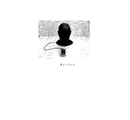
図1に、ダミーヘッドを用いたバイノーラル録音の説明図を示す。
バイノーラル録音では、例えば、人間の頭部形状を模したダミーヘッドと呼ばれる人形の両耳部分にマイクを埋め込んで録音する。この音源をヘッドホンやイヤホンにより聴取した場合、録音時の情報がそのまま再現されるため高臨場感が得られる。
FIG. 1 shows an explanatory diagram of binaural recording using a dummy head.
In binaural recording, for example, microphones are embedded in both ears of a doll called a dummy head that imitates the shape of a human head. When this sound source is listened to by headphones or earphones, the information at the time of recording is reproduced as it is, so that a high sense of presence can be obtained.
しかし、イヤフォンやヘッドフォンの装着は使用者に負担となり、閉塞感も与える。このバイノーラル音源を左右2つのスピーカを用いて耳元で再現する方法がトランスオーラル再生である。
図2に、トランスオーラルシステムの説明図を示す。
トランスオーラル再生を実現するためには、スピーカから耳元へ至るクロストーク成分をキャンセルするために未知の2入力2出力系(H)の逆システムが必要となる[非特許文献1]。この逆システムの推定値が図2の逆フィルタG^となる。このとき、逆フィルタの伝達関数行列G^は次の関係式を満たすことが望まれる。なお、記号上に付される”^”は、推定値の意味であり、入力の都合上、文字の右上に記載するが、数式で示すように、文字の真上に記載されたものと同一である。
However, wearing earphones and headphones is a burden on the user and gives a feeling of blockage. Transoral reproduction is a method of reproducing this binaural sound source at the ear using two left and right speakers.
FIG. 2 shows an explanatory diagram of the transoral system.
In order to realize transoral reproduction, an unknown 2-input 2-output system (H) reverse system is required to cancel the crosstalk component from the speaker to the ear [Non-Patent Document 1]. The estimated value of this inverse system is the inverse filter G ^ of FIG. At this time, it is desired that the transfer function matrix G ^ of the inverse filter satisfies the following relational expression. In addition, "^" attached on the symbol means an estimated value, and it is described in the upper right corner of the character for convenience of input, but as shown in the mathematical formula, it is the same as the one described directly above the character. Is.

従来法[非特許文献2、非特許文献3等]では、まず未知の2入力2出力系を同定し、その結果を用いて逆フィルタ、すなわち逆システムを求めると云った2段階方式をとっていた。そのため、誤差が2重に蓄積すると共に系の変動の影響を受け易いことが想定される。
In the conventional method [Non-Patent
この課題の解決のため2入力2出力系のバイノーラル音声再生方法が提案されているが[特許文献1、特許文献2]、多入力多出力系には対応できていなかった。
また、4入力4出力系の音響再生装置が考案されているが[特許文献3]、順方向の同定を行ってから、その結果を用いて逆同定を行うと云った従来法と同じ2段階方式をとっていた。よって、従来のトランスオーラルシステムと同様の課題を抱えている。さらに、この装置の逆フィルタは固定無限インパルス応答ディジタルフィルタ又は固定IIR(Infinite Impulse Response)デジタルフィルタを用いているため、生活空間での日常使いは困難な場合が想定される。
そのため、複数の試聴者が同じ臨場感を体感できるトランスオーラル再生を実用的なレベルで実現できず、現在まで商品化されていない。また、MIMO通信、地震の振動再現、ロボットの逆キネマティクスなどへの展開も進んでいない。
To solve this problem, a binaural audio reproduction method of a 2-input 2-output system has been proposed [
Further, although a 4-input 4-output system sound reproduction device has been devised [Patent Document 3], the same two steps as the conventional method in which forward identification is performed and then inverse identification is performed using the result. It was a method. Therefore, it has the same problems as the conventional transoral system. Further, since the inverse filter of this device uses a fixed infinite impulse response digital filter or a fixed IIR (Infinite Impulse Response) digital filter, it is expected that daily use in a living space may be difficult.
Therefore, transoral reproduction that allows a plurality of listeners to experience the same sense of presence cannot be realized at a practical level, and has not been commercialized until now. In addition, the development of MIMO communication, vibration reproduction of earthquakes, reverse kinematics of robots, etc. has not progressed.
以上のように、従来は、順方向の伝達関数行列Hを求めてから逆フィルタG^を求めていた(後述の図6参照)。よって、2段階の処理となり、系の変動による誤差や数値誤差の蓄積が無視できない場合が想定される。
また、従来は、入出力が3チャンネル以上の場合に実用的な逆フィルタG^を求めるための方法や、そのような逆フィルタG^を用いた逆システム又はトランスオーラスシステム等が存在しなかった。
As described above, conventionally, the inverse filter G ^ has been obtained after obtaining the transfer function matrix H in the forward direction (see FIG. 6 described later). Therefore, it is a two-step process, and it is assumed that errors due to system fluctuations and accumulation of numerical errors cannot be ignored.
Further, conventionally, there has been no method for obtaining a practical inverse filter G ^ when the input / output is 3 channels or more, an inverse system using such an inverse filter G ^, a trans-aurus system, or the like. ..
本発明は、以上の点に鑑み、未知の多入力多出力系の逆システム・逆フィルタを入出力データから直接同定することを目的とする。 In view of the above points, it is an object of the present invention to directly identify an unknown multi-input multi-output system inverse system / inverse filter from input / output data.
本発明の第1の解決手段によると、
多入力多出力逆フィルタ装置のための多入力多出力系の直接逆同定方法であって、
前記多入力多出力逆フィルタ装置は、
第1〜第[M×M]の逆フィルタG^11〜G^MM
と(Mは、2以上の整数)、
第1〜第Mの出力部U1〜UMと、
を備え、
逆フィルタG^1i,・・・,G^Miは、ソースSi(i=1,・・・,M)を入力し、
出力部Uiは、逆フィルタG^i1,・・・,G^iMの出力の加算値を出力し、
処理部は、前記多入力多出力系を伝達系とした入出力測定値を入力し、
処理部は、逆フィルタG^ij(i,j=1,・・・,M)の各フィルタ係数の推定値g^ij kを、以下の式(6)〜式(11)に従う直接逆同定法による処理を実行して、前記多入力多出力系の入出力測定値から直接同定する、
多入力多出力系の直接逆同定方法が提供される。
According to the first solution of the present invention
A direct inverse identification method for multi-input multi-output systems for multi-input multi-output inverse filter devices.
The multi-input multi-output reverse filter device is
First to first [M × M] inverse filters G ^ 11 to G ^ MM
And (M is an integer greater than or equal to 2),
An
With
For the inverse filter G ^ 1i , ..., G ^ Mi , the source S i (i = 1, ..., M) is input, and the source S i (i = 1, ..., M) is input.
The output unit U i outputs the added value of the outputs of the inverse filters G ^ i 1 , ..., G ^ iM, and outputs the added value.
The processing unit inputs input / output measurement values using the multi-input multi-output system as a transmission system.
The processing unit directly reverse-identifies the estimated value g ^ ij k of each filter coefficient of the inverse filter G ^ ij (i, j = 1, ..., M) according to the following equations (6) to (11). Perform processing by the method and identify directly from the input / output measured values of the multi-input multi-output system.
A direct inverse identification method for a multi-input multi-output system is provided.
g^ij k:N次元ベクトル;j番目のソースからi番目の伝達系の入力又は出力部への逆フィルタのフィルタ係数の推定値。
Kj s,k:N×1行列;j番目のソースを処理する逆フィルタを求めるためのフィルタゲイン。
Yj k:1×N行列;j番目の伝達系の出力又は入力部の出力系列。
e〜i k:i番目の時間領域の誤差
k:時間のインデックス
g ^ ij k : N-dimensional vector; an estimated value of the filter coefficient of the inverse filter from the j-th source to the input or output of the i-th transmission system.
K j s, k : N × 1 matrix; filter gain for finding the inverse filter that processes the j-th source.
Y j k: 1 × N matrix; j-th output or input of the output sequence of the transmission system.
e ~i k: error of the i-th time domain k: index of the time
本発明の第2の解決手段によると、
多入力多出力逆フィルタ装置のための多入力多出力系の直接逆同定装置であって、
前記多入力多出力逆フィルタ装置は、
第1〜第[M×M]の逆フィルタG^11〜G^MM
と(Mは、2以上の整数)、
第1〜第Mの出力部U1〜UMと、
を備え、
逆フィルタG^1i,・・・,G^Miは、ソースSi(i=1,・・・,M)を入力し、
出力部Uiは、逆フィルタG^i1,・・・,G^iMの出力の加算値を出力し、
多入力多出力系の前記直接逆同定装置は、
処理部と、
記憶部と、
を備え、
前記処理部は、前記多入力多出力系を伝達系とした入出力測定値を入力し、
前記処理部は、逆フィルタG^ij(i,j=1,・・・,M)の各フィルタ係数の推定値g^ij kを、以下の式(6)〜式(11)に従う直接逆同定法による処理を実行して、前記多入力多出力系の入出力測定値から直接同定する、
多入力多出力系の直接逆同定装置が提供される。
According to the second solution of the present invention
A direct inverse identification device for a multi-input multi-output system for a multi-input multi-output reverse filter device.
The multi-input multi-output reverse filter device is
First to first [M × M] inverse filters G ^ 11 to G ^ MM
And (M is an integer greater than or equal to 2),
An
With
For the inverse filter G ^ 1i , ..., G ^ Mi , the source S i (i = 1, ..., M) is input, and the source S i (i = 1, ..., M) is input.
The output unit U i outputs the added value of the outputs of the inverse filters G ^ i 1 , ..., G ^ iM, and outputs the added value.
The direct inverse identification device of the multi-input multi-output system is
Processing unit and
Memory and
With
The processing unit inputs input / output measurement values using the multi-input multi-output system as a transmission system.
The processing unit directly reverses the estimated value g ^ ij k of each filter coefficient of the inverse filter G ^ ij (i, j = 1, ..., M) according to the following equations (6) to (11). Perform processing by the identification method to identify directly from the input / output measured values of the multi-input multi-output system.
A direct inverse identification device for a multi-input multi-output system is provided.
g^ij k:N次元ベクトル;j番目のソースからi番目の伝達系の入力又は出力部への逆フィルタのフィルタ係数の推定値。
Kj s,k:N×1行列;j番目のソースを処理する逆フィルタを求めるためのフィルタゲイン。
Yj k:1×N行列;j番目の伝達系の出力又は入力部の出力系列。
e〜i k:i番目の時間領域の誤差
g ^ ij k : N-dimensional vector; an estimated value of the filter coefficient of the inverse filter from the j-th source to the input or output of the i-th transmission system.
K j s, k : N × 1 matrix; filter gain for finding the inverse filter that processes the j-th source.
Y j k: 1 × N matrix; j-th output or input of the output sequence of the transmission system.
e ~i k: i-th error in the time domain
本発明の第3の解決手段によると、
多入力多出力逆フィルタ装置のための多入力多出力系の直接逆同定プログラムであって、
前記多入力多出力逆フィルタ装置は、
第1〜第[M×M]の逆フィルタG^11〜G^MM
と(Mは、2以上の整数)、
第1〜第Mの出力部U1〜UMと、
を備え、
逆フィルタG^1i,・・・,G^Miは、ソースSi(i=1,・・・,M)を入力し、
出力部Uiは、逆フィルタG^i1,・・・,G^iMの出力の加算値を出力し、
処理部が、前記多入力多出力系を伝達系とした入出力測定値を入力するステップと、
処理部が、逆フィルタG^ij(i,j=1,・・・,M)の各フィルタ係数の推定値g^ij kを、以下の式(6)〜式(11)に従う直接逆同定法による処理を実行して、前記多入力多出力系の入出力測定値から直接同定するステップと、
前記処理部が、同定した各フィルタ係数の推定値g^ij kを、記憶部に記憶するステップと、
をコンピュータに実行させるための多入力多出力系の直接逆同定プログラムが提供される。
According to the third solution of the present invention
A direct inverse identification program for multi-input multi-output systems for multi-input multi-output inverse filter devices.
The multi-input multi-output reverse filter device is
First to first [M × M] inverse filters G ^ 11 to G ^ MM
And (M is an integer greater than or equal to 2),
An
With
For the inverse filter G ^ 1i , ..., G ^ Mi , the source S i (i = 1, ..., M) is input, and the source S i (i = 1, ..., M) is input.
The output unit U i outputs the added value of the outputs of the inverse filters G ^ i 1 , ..., G ^ iM, and outputs the added value.
A step in which the processing unit inputs input / output measurement values using the multi-input multi-output system as a transmission system, and
The processing unit directly reverse-identifies the estimated value g ^ ij k of each filter coefficient of the inverse filter G ^ ij (i, j = 1, ..., M) according to the following equations (6) to (11). The step of executing the processing by the method and identifying directly from the input / output measured values of the multi-input multi-output system,
And storing said processing unit, an estimate g ^ ij k of each filter coefficients identified in the storage unit,
A direct inverse identification program for a multi-input, multi-output system is provided to allow a computer to execute.
g^ij k:N次元ベクトル;j番目のソースからi番目の伝達系の入力又は出力部への逆フィルタのフィルタ係数の推定値。
Kj s,k:N×1行列;j番目のソースを処理する逆フィルタを求めるためのフィルタゲイン。
Yj k:1×N行列;j番目の伝達系の出力又は入力部の出力系列。
e〜i k:i番目の時間領域の誤差
g ^ ij k : N-dimensional vector; an estimated value of the filter coefficient of the inverse filter from the j-th source to the input or output of the i-th transmission system.
K j s, k : N × 1 matrix; filter gain for finding the inverse filter that processes the j-th source.
Y j k: 1 × N matrix; j-th output or input of the output sequence of the transmission system.
e ~i k: i-th error in the time domain
本発明の第4の解決手段によると、
多入力多出力逆フィルタ装置のための多入力多出力系の直接逆同定プログラムを記録したコンピュータ読み取り可能な記録媒体であって、
前記多入力多出力逆フィルタ装置は、
第1〜第[M×M]の逆フィルタG^11〜G^MM
と(Mは、2以上の整数)、
第1〜第Mの出力部U1〜UMと、
を備え、
逆フィルタG^1i,・・・,G^Miは、ソースSi(i=1,・・・,M)を入力し、
出力部Uiは、逆フィルタG^i1,・・・,G^iMの出力の加算値を出力し、
処理部が、前記多入力多出力系を伝達系とした入出力測定値を入力するステップと、
処理部が、逆フィルタG^ij(i,j=1,・・・,M)の各フィルタ係数の推定値g^ij kを、以下の式(6)〜式(11)に従う直接逆同定法による処理を実行して、前記多入力多出力系の入出力測定値から直接同定するステップと、
前記処理部が、同定した各フィルタ係数の推定値g^ij kを、記憶部に記憶するステップと、
をコンピュータに実行させるための多入力多出力系の直接逆同定プログラムを記録したコンピュータ読み取り可能な記録媒体が提供される。
According to the fourth solution of the present invention
A computer-readable recording medium that records a direct inverse identification program for a multi-input, multi-output system for a multi-input, multi-output reverse filter device.
The multi-input multi-output reverse filter device is
First to first [M × M] inverse filters G ^ 11 to G ^ MM
And (M is an integer greater than or equal to 2),
An
With
For the inverse filter G ^ 1i , ..., G ^ Mi , the source S i (i = 1, ..., M) is input, and the source S i (i = 1, ..., M) is input.
The output unit U i outputs the added value of the outputs of the inverse filters G ^ i 1 , ..., G ^ iM, and outputs the added value.
A step in which the processing unit inputs input / output measurement values using the multi-input multi-output system as a transmission system, and
The processing unit directly reverse-identifies the estimated value g ^ ij k of each filter coefficient of the inverse filter G ^ ij (i, j = 1, ..., M) according to the following equations (6) to (11). The step of executing the processing by the method and identifying directly from the input / output measured values of the multi-input multi-output system,
And storing said processing unit, an estimate g ^ ij k of each filter coefficients identified in the storage unit,
A computer-readable recording medium is provided that records a direct inverse identification program for a multi-input, multi-output system for causing a computer to execute.
g^ij k:N次元ベクトル;j番目のソースからi番目の伝達系の入力又は出力部への逆フィルタのフィルタ係数の推定値。
Kj s,k:N×1行列;j番目のソースを処理する逆フィルタを求めるためのフィルタゲイン。
Yj k:1×N行列;j番目の伝達系の出力又は入力部の出力系列。
e〜i k:i番目の時間領域の誤差
g ^ ij k : N-dimensional vector; an estimated value of the filter coefficient of the inverse filter from the j-th source to the input or output of the i-th transmission system.
K j s, k : N × 1 matrix; filter gain for finding the inverse filter that processes the j-th source.
Y j k: 1 × N matrix; j-th output or input of the output sequence of the transmission system.
e ~i k: i-th error in the time domain
本発明の第5の解決手段によると、
多入力多出力系を伝達系とする多入力多出力逆フィルタ装置であって、
第1〜第[M×M]の逆フィルタG^11〜G^MM
と(Mは、2以上の整数)、
第1〜第Mの出力部U1〜UMと、
を備え、
逆フィルタG^1i,・・・,G^Miは、ソースSi(i=1,・・・,M)を入力し、
出力部Uiは、逆フィルタG^i1,・・・,G^iMの出力の加算値を出力し、
処理部により、前記多入力多出力系を伝達系とした入出力測定値を入力し、以下の式(6)〜式(11)に従う直接逆同定法による処理を実行して、前記多入力多出力系の入出力測定値から直接同定した各フィルタ係数の推定値g^ij kが、逆フィルタG^ij(i,j=1,・・・,M)に設定された、多入力多出力逆フィルタ装置が提供される。
According to the fifth solution of the present invention
It is a multi-input multi-output inverse filter device that uses a multi-input multi-output system as a transmission system.
First to first [M × M] inverse filters G ^ 11 to G ^ MM
And (M is an integer greater than or equal to 2),
An
With
For the inverse filter G ^ 1i , ..., G ^ Mi , the source S i (i = 1, ..., M) is input, and the source S i (i = 1, ..., M) is input.
The output unit U i outputs the added value of the outputs of the inverse filters G ^ i 1 , ..., G ^ iM, and outputs the added value.
The processing unit inputs input / output measurement values using the multi-input multi-output system as a transmission system, executes processing by the direct inverse identification method according to the following equations (6) to (11), and executes the multi-input multi-output system. Multi-input multi-output in which the estimated value g ^ ij k of each filter coefficient directly identified from the input / output measurement values of the output system is set in the inverse filter G ^ ij (i, j = 1, ..., M). An inverse filter device is provided.
g^ij k:N次元ベクトル;j番目のソースからi番目の伝達系の入力又は出力部への逆フィルタのフィルタ係数の推定値。
Kj s,k:N×1行列;j番目のソースを処理する逆フィルタを求めるためのフィルタゲイン。
Yj k:1×N行列;j番目の伝達系の出力又は入力部の出力系列。
e〜i k:i番目の時間領域の誤差
g ^ ij k : N-dimensional vector; an estimated value of the filter coefficient of the inverse filter from the j-th source to the input or output of the i-th transmission system.
K j s, k : N × 1 matrix; filter gain for finding the inverse filter that processes the j-th source.
Y j k: 1 × N matrix; j-th output or input of the output sequence of the transmission system.
e ~i k: i-th error in the time domain
本発明の第6の解決手段によると、
多入力多出力系を伝達系とする多入力多出力逆フィルタ装置を用いた多入力多出力逆フィルタ方法であって、
前記多入力多出力逆フィルタ装置は、
第1〜第[M×M]の逆フィルタG^11〜G^MM
と(Mは、2以上の整数)、
第1〜第Mの出力部U1〜UMと、
を備え、
逆フィルタG^1i,・・・,G^Miは、ソースSi(i=1,・・・,M)を入力し、
出力部Uiは、逆フィルタG^i1,・・・,G^iMの出力の加算値を出力し、
処理部により、前記多入力多出力系を伝達系とした入出力測定値を入力し、以下の式(6)〜式(11)に従う直接逆同定法による処理を実行して、前記多入力多出力系の入出力測定値から直接同定した各フィルタ係数の推定値g^ij kが、逆フィルタG^ij(i,j=1,・・・,M)に設定された、多入力多出力逆フィルタ装置を用いた多入力多出力逆フィルタ方法が提供される。
According to the sixth solution of the present invention
This is a multi-input multi-output reverse filter method using a multi-input multi-output reverse filter device that uses a multi-input multi-output system as a transmission system.
The multi-input multi-output reverse filter device is
First to first [M × M] inverse filters G ^ 11 to G ^ MM
And (M is an integer greater than or equal to 2),
An
With
For the inverse filter G ^ 1i , ..., G ^ Mi , the source S i (i = 1, ..., M) is input, and the source S i (i = 1, ..., M) is input.
The output unit U i outputs the added value of the outputs of the inverse filters G ^ i 1 , ..., G ^ iM, and outputs the added value.
The processing unit inputs input / output measurement values using the multi-input multi-output system as a transmission system, executes processing by the direct inverse identification method according to the following equations (6) to (11), and executes the multi-input multi-output system. Multi-input multi-output in which the estimated value g ^ ij k of each filter coefficient directly identified from the input / output measurement values of the output system is set in the inverse filter G ^ ij (i, j = 1, ..., M). A multi-input multi-output inverse filter method using an inverse filter device is provided.
g^ij k:N次元ベクトル;j番目のソースからi番目の伝達系の入力又は出力部への逆フィルタのフィルタ係数の推定値。
Kj s,k:N×1行列;j番目のソースを処理する逆フィルタを求めるためのフィルタゲイン。
Yj k:1×N行列;j番目の伝達系の出力又は入力部の出力系列。
e〜i k:i番目の時間領域の誤差
g ^ ij k : N-dimensional vector; an estimated value of the filter coefficient of the inverse filter from the j-th source to the input or output of the i-th transmission system.
K j s, k : N × 1 matrix; filter gain for finding the inverse filter that processes the j-th source.
Y j k: 1 × N matrix; j-th output or input of the output sequence of the transmission system.
e ~i k: i-th error in the time domain
本発明によると、未知の多入力多出力系の逆システム・逆フィルタを入出力データから直接同定することができる。
According to the present invention, an unknown multi-input multi-output system inverse system / inverse filter can be identified directly from input / output data.
A.概要
本発明及び/又は本実施の形態によると、例えば、以下の方法又は装置を提供することができる。
1) 多入力多出力系の逆システムを入出力データから直接実時間で同定する方法・装置。
2) 上記で求めた逆フィルタを用いて多入力多出力系の等化器を構築する方法・装置。
3) 上記の逆フィルタを用いて複数の人が高臨場感を共有できる音場再生方法・装置。
4) 上記の逆フィルタを用いて所望の出力を与えるシステムの入力を生成する方法・装置。
未知のM入力M出力系HのM×M個の経路の伝達関数をそれぞれHij, i,j=1,・・・,Mとし、z変換された系の入力をU1,・・・,UM、系の出力をY1,・・・,YMとすれば次のように表すことができる。ここで、Mは、予め定められた2以上の整数であり、本発明及び/又は本実施の形態は、特に、Mが3以上の整数とした多入力多出力系にも適用することができる。
A. Overview According to the present invention and / or the present embodiment, for example, the following methods or devices can be provided.
1) A method / device for identifying the reverse system of a multi-input multi-output system directly from input / output data in real time.
2) A method / device for constructing a multi-input multi-output equalizer using the inverse filter obtained above.
3) A sound field reproduction method / device that allows multiple people to share a high sense of presence using the above inverse filter.
4) A method / apparatus for generating a system input that gives a desired output using the above inverse filter.
The transfer functions of the M × M paths of the unknown M input M output system H are set to H ij , i, j = 1, ···, M, respectively, and the inputs of the z-transformed system are U 1 , ···. , U M , If the output of the system is Y 1 , ..., Y M , it can be expressed as follows. Here, M is a predetermined integer of 2 or more, and the present invention and / or the present embodiment can be applied particularly to a multi-input multi-output system in which M is an integer of 3 or more. ..
本発明及び/又は本実施の形態の特徴のひとつとしては、例えば、事前にHij, i,j=1,・・・,Mを求めることなく、直接、次式を満たす逆フィルタG^ij, i,j=1,・・・,Mを求めることである。
One of the features of the present invention and / or the present embodiment is, for example, an inverse filter G ^ ij that directly satisfies the following equation without obtaining H ij, i, j = 1, ..., M in advance. , I, j = 1, ..., M.
また、G^ij、Ui、Yjは、それぞれ、g^ij k、ui k、yj kのz変換である。
なお、記号の上に付される”^”は、推定値の意味である。また、”〜”、”U”等は、便宜上付加した記号である。これらの記号は、入力の都合上、文字の右上に記載するが、数式で示すように、文字の真上に記載されたものと同一である。また、数式中太字で標記される記号、Y、H、U、G、g、L、C、I,K、R等は行列であり、本来数式で示すように太文字で記されるものであるが、出願形式の制約上、普通の文字で記載する。
Further, G ^ ij , U i , and Y j are z-transforms of g ^ ij k , u i k , and y j k, respectively.
The "^" attached above the symbol means an estimated value. Further, "~", "U" and the like are symbols added for convenience. These symbols are written in the upper right corner of the letters for convenience of input, but as shown in the mathematical formula, they are the same as those written directly above the letters. In addition, the symbols marked in bold in the mathematical formula, Y, H, U, G, g, L, C, I, K, R, etc. are matrices, and are originally written in bold as shown in the mathematical formula. However, due to restrictions on the application format, it will be written in ordinary characters.
B.直接逆同定法
図7は、M入力M出力系の直接逆同定法の説明図を示す。
ここでは、M入力M出力系の一例として、音響系について説明するが、本発明及び/又は本実施の形態は、通信系、振動系、制御系等に適用することができる。例えば、通信系、振動系、制御系等の場合には、スピーカとマイクを、対応する送信機・送信部・送信器等の出力部と、対応する受信機・受信器・受信部・測定部・検出部等の入力部等に置き換えればよく、また、音源を、対応する信号源・送信源・情報源等のソースに置き換えればよい。ただし、例えば、伝達系への各入力Uiのソース(例、音源)Xiは互いに無相関とする。本実施の形態では、U1,...,UMの無相関性を用いて、通過領域の等化とクロストークキャンセルを並列分散的に実行している。U1+...+UMと重なっていても、U1,...,UMが無相関であれば、それぞれ別々に処理できる。
なお、順方向の同定(順同定)では、U1,...,UMが無相関であれば、入力信号の相関行列はブロック対角行列となり、並列分散的に実行することができる。本実施の形態(逆同定)では、U1,...,UMを無相関としても、一般に逆システムの入力信号Y1,...,YMの相関行列がブロック対角行列となる保証はない。
B. Direct inverse identification method
FIG. 7 shows an explanatory diagram of the direct inverse identification method of the M input M output system.
Here, the acoustic system will be described as an example of the M input M output system, but the present invention and / or the present embodiment can be applied to a communication system, a vibration system, a control system, and the like. For example, in the case of a communication system, a vibration system, a control system, etc., a speaker and a microphone are used as an output unit such as a corresponding transmitter / transmitter / transmitter and a corresponding receiver / receiver / receiver / measurement unit. -The sound source may be replaced with an input unit such as a detection unit, or the sound source may be replaced with a source such as a corresponding signal source, transmission source, or information source. However, for example, the sources (eg, sound sources) X i of each input U i to the transmission system are uncorrelated with each other. In this embodiment, U 1, ..., using a de-correlation of the U M, running equalization and crosstalk cancellation passage area parallel distributed manner. U 1 +. .. .. Even if it overlaps with + U M , U 1 ,. .. .. If , UM are uncorrelated, they can be processed separately.
In the forward identification (forward identification), U 1 , ... .. .. If UM is uncorrelated, the correlation matrix of the input signal is a block diagonal matrix and can be executed in parallel and distributed. In this embodiment (reverse identification), U 1 , ... .. .. Even uncorrelated U M, the
直接逆同定法は、スピーカ等の伝達系・未知系Hへの入力からマイク等の伝達系・未知系Hの出力への信号到達時間差による相関行列のブロック対角化 The direct inverse identification method is a block diagonalization of the correlation matrix based on the difference in signal arrival time from the input to the transmission system / unknown system H such as a speaker to the output of the transmission system / unknown system H such as a microphone.
![]()
![]()
[記号の説明]
g^ij k:N次元ベクトル;j番目のソース(例、音源)からi番目の伝達系・未知系Hへの入力(例、スピーカ等の出力部)への逆フィルタのフィルタ係数の推定値。
Kj s,k:N×1行列;j番目のソース(例、音源)を処理する逆フィルタを求めるためのフィルタゲイン。
Yj k:1×N行列;j番目の伝達系・未知系Hからの出力(例、マイク等の入力部の出力系列)。
N:タップ数(インパルス応答長)
k:時間のインデックス
E〜 i:時間領域の誤差e〜i kのz変換
[Explanation of symbols]
g ^ ij k : N-dimensional vector; estimated value of the filter coefficient of the inverse filter from the j-th source (eg, sound source) to the input to the i-th transmission system / unknown system H (eg, output part of a speaker, etc.) ..
K j s, k : N × 1 matrix; filter gain for finding the inverse filter that processes the j-th source (eg, sound source).
Y j k: 1 × N matrix; j-th output from the transmission system, the unknown system H (eg, the output sequence of the input unit such as a microphone).
N: Number of taps (impulse response length)
k: time of the index E ~ i: z conversion of error e ~i k of time domain
ここで、直接逆同定法の式(6)〜(7)のフィルタゲインK1 s,k〜KM s,kが式(9)〜(10)のフィルタゲインK1 s,k〜KM s,kと等しいこと、すなわちフィルタ係数はM×M個あるが、フィルタゲインはM個で済むことが示される。
次に、式(6)〜式(11)の直接逆同定法によって得られた逆フィルタG^が未知の多入力多出力系Hの逆システムになること(すなわち、合成システムG^H=HG^がオールパス特性をもつという証明)を示す。
図7のU1に注意すればG^11,・・・,G^1Mは次式を満たすことがわかる。
Here, the filter gain K 1 s of the formula directly opposite identification method (6) ~ (7), k ~K M s, k is the filter gain K 1 s of formula (9) ~ (10), k ~K M It is shown that it is equal to s and k , that is, there are M × M filter coefficients, but only M filter gains are required.
Next, the inverse filter G ^ obtained by the direct inverse identification methods of equations (6) to (11) becomes the inverse system of the unknown multi-input multi-output system H (that is, the synthesis system G ^ H = HG). Proof that ^ has all-pass characteristics) is shown.
If attention is paid to U 1 in FIG. 7, it can be seen that G ^ 11 , ..., G ^ 1M satisfies the following equation.
この両辺に右からU1を掛け、期待値をとれば次式を得る。
Multiply these two sides by U 1 from the right, and take the expected value to obtain the following equation.
以上により、直接逆同定法が平均収束すれば(E{g^ij k}=E{g^ij k−1})、
From the above, if the direct inverse identification method converges on average (E {g ^ ij k } = E {g ^ ij k-1 }),
特に、直接逆同定法では適応フィルタとしてJ−高速H∞フィルタを用いると効果的である。J−高速H∞フィルタをベースにした直接逆同定法の場合、各フィルタゲインKi s,k, i=1,・・・,M は次の再帰式で更新される。なお、Ki s,kは、他にも適宜の適応フィルタ等のアルゴリズム・処理により求めても良い(例えば、特許第4067269号公報、特許第4444919号公報、特許第5196653号公報、等参照)。
In particular, in the direct inverse identification method, it is effective to use a J- fast H ∞ filter as an adaptive filter. When the J - fast H ∞ reverse identification method directly that is based on the filter, the
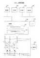
図8は、M入力M出力系の入力再生及び逆フィルタ装置の説明図を示す。
多入力多出力系を伝達系とする多入力多出力逆フィルタ装置200は、逆フィルタG^11〜G^MM、出力部(U1〜UM 参照)と、逆フィルタG^i1,・・・,G^iMからの出力を入力して加算して出力部に出力する加算器i(i=1,・・・,M)と、を備える。逆フィルタG^1i,・・・,G^Miは、ソースSi(i=1,・・・,M)を入力し、出力部(Ui 参照)は、加算器1〜Mの出力を出力する。
FIG. 8 shows an explanatory diagram of an input reproduction and inverse filter device of the M input M output system.
Multiple-input multiple-output
再生時は、図8のように図7で求めた逆フィルタG^を用いて構築したM×Mトランスオーラルシステム等のM×MシステムHG^にソース(例、音源)S1,・・・,SMを入力すれば、G^H=HG^=z-DIの関係式より、各入力部(例、マイク)の位置でそれぞれY1≒z-DS1,・・・,YM≒z-DSMが現れる。この際、S1,・・・,SMは互いに無相関である必要はない。
なお、S1からの信号(例、音)はY1だけに伝わり、同様にS2,・・・,SMからの信号(例、音)はそれぞれY2,・・・,YMだけに伝わるようにすることをトランスオーラル再生と言う。ソースの信号(例、音源の音)を逆フィルタG^で処理した後に出力部(例、スピーカ)(U1〜UM 参照)から出力すれば、S1からの信号(例、音)はY2〜YMには伝わらない。これをクロストークキャンセルと言う。
以上の逆同定からトランスオーラル再生までの手順を、後述の図9のフローチャートに示した。
At the time of reproduction, the source (eg, sound source) S 1 , ... To the M × M system HG ^ such as the M × M transoral system constructed by using the inverse filter G ^ obtained in FIG. 7 as shown in FIG. , SM is input, and from the relational expression of G ^ H = HG ^ = z- DI , Y 1 ≒ z -DS 1 ,, ..., Y at the position of each input unit (eg, microphone), respectively. M ≈ z -DS M appears. In this case, S 1, ···, S M need not be mutually uncorrelated.
The signal (e.g., sound) from S 1 is transmitted to only Y 1, similarly S 2, · · ·, signals (e.g., sound) from S M, each Y 2, ···, Y M only Transoral reproduction is the process of transmitting to the sound. Signal source if the output from the output unit after processing (for example, sound source sound) in the inverse filter G ^ (e.g., a speaker) (see U 1 ~U M), the signal from S 1 (e.g., sound) is not transmitted to the Y 2 ~Y M. This is called crosstalk cancellation.
The procedure from the above reverse identification to transoral regeneration is shown in the flowchart of FIG. 9 described later.
C.多入力多出力系の直接同定法の装置及び方法
図3は、逆同定装置の構成図である。
逆同定装置100は、中央処理装置(CPU)である処理部101、入力部102、出力部103、表示部104及び記憶部105を有する。また、処理部101、入力部102、出力部103、表示部104及び記憶部105は、スター又はバス等の適宜の接続手段で接続されている。記憶部105は、測定値、予め定められた値、未知・既知のデータ、逆フィルタに関するデータ(フィルタ係数等)、処理部101により計算された各種データ等が記憶され、処理部101により、記憶部105に対して、それらの各データ等が必要に応じて書込み及び/又は読み出しされる。
C. Devices and methods for direct identification of multi-input, multi-output systems
FIG. 3 is a block diagram of the inverse identification device.
The
図4は、逆同定装置の他の構成図である。
逆同定装置100’では、測定部107が入出力を測定し、それらの測定値を入力部102又はI/F106を介して、記憶部105に入力するようにした点が、主に図3の逆同定装置100と異なる。なお、記憶部105は、例えば、逆フィルタに関するデータを記憶する逆フィルタデータファイル151、入出力データを記憶する入出力測定値ファイル152、等の適宜のファイルを含むようにしてもよい(図3においても同様)。また、入出力測定値ファイル152等のファイルは、例えば、リングバッファを用いても良い。
FIG. 4 is another configuration diagram of the inverse identification device.
In the inverse identification device 100', the
図9に、直接逆同定法を用いたM×Mトランスオーラル再生のフローチャートを示す。以下に各ステップの処理について説明する。
(S1) 処理部101は、フィルタゲインKi s,kの再帰変数を初期化する。たとええば、処理部101は、式(29)に示すような初期条件を記憶部105から読み出し、又は、初期条件を入力部102から入力し、Ri e,−1,R,ρ,γf,ε0,K〜i −1,P^i 0|−1,L〜i −1,Ri r,−1等に初期値を代入(式(29))する。なお、k=0とする。
(S2) 処理部101は、システムの入出力{ui k},{yi k}を測定する。なお、システムの入出力は、処理部101が予め複数のkについてのデータを測定して記憶部105に保存しておき、kに従い、処理の際にその都度データを読み出すようにしてもよい。
(S3) 処理部101は、フィルタゲインKi s,kを式(23)から式(28)により計算する。
(S4) 処理部101は、直接逆同定法で、g^ij kを式(6)から式(11)により求める。
(S5) 処理部101は、各フィルタ係数の推定値が収束したとき(||g^ij k−g^ij k−1||≒0)、トランスオーラル再生の処理(S7)へ移行する。一方、各フィルタ係数の推定値が収束しないとき、ステップS6へ移行する。
(S6) 処理部101は、時間のインデックスkに1を加え、ステップS2に戻る。
FIG. 9 shows a flowchart of M × M transoral reproduction using the direct inverse identification method. The processing of each step will be described below.
(S1) The
(S2)
(S3)
(S4) The
(S5) When the estimated values of the filter coefficients have converged (|| g ^ ij k − g ^ ij k-1 || ≈ 0), the
(S6) The
(S7)トランスオーラル再生の処理(S7)へ移行すると、図8に示したM入力M出力系の逆フィルタG^ijの特性を、求めたg^ij k=[g^ij k(0),・・・,g^ij k(N−1)]Tに設定することにより、多入力多出力系の逆フィルタ装置を構築する。構築された逆フィルタ装置は、各々のソース{Si}(音源等)を多入力する。
(S8)逆フィルタ装置は、M×Mトランスオーラル再生のためにG^Sを計算して、出力する。
(S9)逆フィルタ装置は、計算したG^Sを各々の出力部{Ui 参照}(スピーカ等)から多出力する。
(S7) After shifting to the transoral reproduction process (S7), the characteristics of the inverse filter G ^ ij of the M input M output system shown in FIG. 8 were obtained by g ^ ij k = [g ^ ij k (0)). , ..., g ^ ij k (N-1)] By setting to T , a multi-input multi-output system inverse filter device is constructed. The constructed inverse filter device inputs a large number of each source {S i } (sound source, etc.).
(S8) The inverse filter device calculates and outputs G ^ S for M × M transoral reproduction.
(S9) inverse filter apparatus multiple output the calculated G ^ S from each of the output section {See U i} (speaker etc.).
なお、処理部101は、各ステップで求めた適宜の中間値、最終値、測定値及び/又は計算値等を必要に応じて適宜記憶部105に記憶し、また、記憶部105から読み出すようにしてもよい。
The
トランスオーラルシステムでは、G^は{g^ij k}のz変換、Sは{sik}のz変換をそれぞれの成分にもつ。その掛けたものG^Sの逆z変換はg^ij kとsikの畳み込みg^ij k*sikとなる。インパルス応答{g^ij k}をもつシステムに信号{sik}を入力すると、線形システムの出力はg^ij k*sikとなる。例えば、音源Sを予め求めた逆フィルタG^で処理(G^S)してからスピーカに出力すれば、右の音源の音は右のマイク、左の音源の音は左のマイクにしか届かないようにできる。これは合成システムHG^=G^Hが入力をそのまま出力するシステムになることを利用している。よって、G^Sはスピーカへ出力する前に音源Sの前処理をしている。 In the transoral system, G ^ has a z-transform of {g ^ ij k }, and S has a z-transform of {s ik } for each component. The inverse z-transform of the over ones G ^ S is the convolution g ^ ij k * s ik of g ^ ij k and s ik. When a signal {s ik } is input to a system having an impulse response {g ^ ij k }, the output of the linear system is g ^ ij k * s ik . For example, if the sound source S is processed (G ^ S) by the inverse filter G ^ obtained in advance and then output to the speaker, the sound of the right sound source reaches only the right microphone and the sound of the left sound source reaches only the left microphone. You can avoid it. This utilizes the fact that the synthesis system HG ^ = G ^ H becomes a system that outputs the input as it is. Therefore, G ^ S preprocesses the sound source S before outputting it to the speaker.
図10に、2人の試聴者で同じ音源(SL,SR)の臨場感を共有して楽しむことができる4x4トランスオーラルシステムの説明図を表す。
同様にチャンネル数を増やせば、原理的には3人、4人、・・・でも同じ音源の臨場感を共有できる。
例えば、図10の左側の音源(SL,SR)を日本語放送、右側の音源(SL,SR)を英語放送にすれば、同じ空間において左右のテレビ視聴者がそれぞれの言語でテレビを見ることもできる。
Figure 10 represents the same sound source (S L, S R) illustration of 4x4 transaural system that can be enjoyed by sharing realism at two listening person.
Similarly, if the number of channels is increased, in principle, three people, four people, and so on can share the same sense of presence of the sound source.
For example, the left side of the sound source (S L, S R) in FIG. 10 the Japanese broadcast, the right side of the sound source (S L, S R) if the English broadcast, the left and right of television viewers in the same space in each language You can also watch TV.
D. 実験例
(1) 3×3トランスオーラルシステム
図11に、3入力3出力系の直接逆同定法と3×3トランスオーラルシステムの検証実験の例の説明図を示す。
また、図12から図17にそのときの各スピーカからの各マイクの信号の説明図を示す。
図12は、左スピーカから左マイクの伝達信号を表す図、図13は、右または中央スピーカから左マイクの伝達信号を表す図、図14は、中央スピーカから中央マイクの伝達信号を表す図、図15は、右または左スピーカから中央マイクの伝達信号を表す図、図16は、右スピーカから右マイクの伝達信号を表す図、また、図17は、左または中央スピーカから右マイクの伝達信号を表す図、である。
これより、本発明及び/又は本実施の形態によって3入力3出力系でもクロストークキャンセルが良好に行われることが確認できた。
D. Experimental example
(1) 3 × 3 Transoral System FIG. 11 shows an explanatory diagram of an example of a direct inverse identification method of a 3-input 3-output system and a verification experiment of a 3 × 3 transoral system.
Further, FIGS. 12 to 17 show explanatory diagrams of signals of each microphone from each speaker at that time.
FIG. 12 is a diagram showing a transmission signal from the left speaker to the left microphone, FIG. 13 is a diagram showing a transmission signal from the right or center speaker to the left microphone, and FIG. 14 is a diagram showing a transmission signal from the center speaker to the center microphone. FIG. 15 is a diagram showing the transmission signal of the central microphone from the right or left speaker, FIG. 16 is a diagram showing the transmission signal of the right microphone from the right speaker, and FIG. 17 is a diagram showing the transmission signal of the right microphone from the left or center speaker. It is a figure showing.
From this, it was confirmed that the crosstalk cancellation is satisfactorily performed even in the 3-input 3-output system according to the present invention and / or the present embodiment.
(2) 4×4トランスオーラルシステム
図18に、4入力4出力系の直接逆同定法と4×4トランスオーラルシステムの検証実験の例の説明図を示す。
また、図5は、スピーカーSP1、SP2、SP3、SP4からマイクMic1への伝達特性の図を表している。
この例では、SP1からMic1への伝達特性は200Hz以上はほぼ平坦となり、良好な通過特性を示している。一方、SP2、SP3、SP4からマイクMic1への伝達特性は200Hz以上でほぼ10〜20dB利得が減衰しており、クロストークがキャンセルされている様子がわかる。
(2) 4 × 4 Transoral System FIG. 18 shows an explanatory diagram of an example of a direct inverse identification method of a 4-input 4-output system and a verification experiment of a 4 × 4 transoral system.
Further, FIG. 5 shows a diagram of transmission characteristics from the speakers SP1, SP2, SP3, and SP4 to the microphone Mic1.
In this example, the transfer characteristics from SP1 to Mic1 are almost flat above 200 Hz, showing good passage characteristics. On the other hand, the transmission characteristics from SP2, SP3, and SP4 to the microphone Mic1 are such that the gain of about 10 to 20 dB is attenuated at 200 Hz or higher, and it can be seen that the crosstalk is cancelled.
E.実施の形態の効果、本発明/本実施の形態の応用等
図6は、本発明及び/又は本実施の形態と従来法との違いを示す説明図である。
本実施の形態によると、未知の多入力多出力系の逆システムを1回の実時間同定で可能とすることができる。また、本実施の形態によると、逆同定で得られた逆フィルタを用いて、多入力多出力系の等化器の構築や所望の出力を与えるシステムの入力の生成を可能とすることができる。特に、本実施の形態によると、複数の人が高臨場感を共有できる音場再生を実現することができる。
E. Effects of embodiments, applications of the present invention / embodiments, etc.
FIG. 6 is an explanatory diagram showing a difference between the present invention and / or the present embodiment and the conventional method.
According to this embodiment, an unknown multi-input multi-output reverse system can be enabled with a single real-time identification. Further, according to the present embodiment, it is possible to construct an equalizer of a multi-input multi-output system and generate an input of a system that gives a desired output by using the inverse filter obtained by the inverse identification. .. In particular, according to the present embodiment, it is possible to realize sound field reproduction in which a plurality of people can share a high sense of presence.
以上のように、本発明及び/又は本実施の形態によると、例えば、未知の多入力多出力系の逆システムを入出力データから直接実時間で同定する方法が提供される。本発明及び/又は本実施の形態によると、例えば、複数の人が共通の音源あるいは異なる音源を高臨場感で楽しむ音場再生装置の実用化が可能となる。また、上述では、多入力多出力系の一例として、主に音響系について説明したが、本発明及び/又は本実施の形態は、例えば、通信系、振動系、制御系等にも適用することができる。そして、本発明及び/又は本実施の形態によると、例えば、その成果は光通信の等化器、MIMO通信システムにおける空間多重化、地震の再現、ロボットの制御などの課題解決に大きく貢献する。 As described above, according to the present invention and / or the present embodiment, for example, a method for identifying an unknown reverse system of a multi-input multi-output system directly from input / output data in real time is provided. According to the present invention and / or the present embodiment, for example, it is possible to put into practical use a sound field reproducing device in which a plurality of people enjoy a common sound source or different sound sources with a high sense of presence. Further, in the above description, the acoustic system has been mainly described as an example of the multi-input multi-output system, but the present invention and / or the present embodiment may be applied to, for example, a communication system, a vibration system, a control system, and the like. Can be done. According to the present invention and / or the present embodiment, for example, the result greatly contributes to solving problems such as an equalizer of optical communication, spatial multiplexing in a MIMO communication system, reproduction of an earthquake, and control of a robot.
本発明及び/又は本実施の形態の直接逆同定方法又は直接逆同定装置・システムは、その各手順をコンピュータに実行させるための直接逆同定プログラム、直接逆同定プログラムを記録したコンピュータ読み取り可能な記録媒体、直接逆同定プログラムを含みコンピュータの内部メモリにロード可能なプログラム製品、そのプログラムを含むサーバ等のコンピュータ、等により提供されることができる。
The direct reverse identification method or the direct reverse identification device / system of the present invention and / or the present embodiment is a computer-readable record of a direct reverse identification program and a direct reverse identification program for causing a computer to execute each procedure. It can be provided by a medium, a program product that includes a direct inverse identification program and can be loaded into the internal memory of the computer, a computer such as a server that includes the program, and the like.
100 逆同定装置
101 処理部
102 入力部
103 出力部
104 表示部
105 記憶部
200 逆フィルタ装置
100
Claims (15)
前記多入力多出力逆フィルタ装置は、
第1〜第[M×M]の逆フィルタG^11〜G^MM
と(Mは、2以上の整数)、
第1〜第Mの出力部と、
を備え、
逆フィルタG^1i,・・・,G^Miは、ソースSi(i=1,・・・,M)を入力し、
第iの出力部は、逆フィルタG^i1,・・・,G^iMの出力の加算値を出力し、
処理部は、前記多入力多出力系を伝達系とした入出力測定値を入力し、
前記処理部は、逆フィルタG^ij(i,j=1,・・・,M)の各フィルタ係数の推定値g^ij kを、以下の式(6)〜式(11)に従う直接逆同定法による処理を実行して、前記多入力多出力系の入出力測定値から直接同定する、
多入力多出力系の直接逆同定方法。
g^ij k:N次元ベクトル;j番目のソースからi番目の伝達系の入力又は出力部への逆フィルタのフィルタ係数の推定値。
Kj s,k:N×1行列;j番目のソースを処理する逆フィルタを求めるためのフィルタゲイン。
Yj k:1×N行列;j番目の伝達系の出力又は入力部の出力系列。
e〜i k:i番目の時間領域の誤差
k:時間のインデックス
u i k−D :i番目の伝達系の入力 (Dはサンプル遅れを表す。)
A direct inverse identification method for multi-input multi-output systems for multi-input multi-output inverse filter devices.
The multi-input multi-output reverse filter device is
First to first [M × M] inverse filters G ^ 11 to G ^ MM
And (M is an integer greater than or equal to 2),
The first to third output units and
With
For the inverse filter G ^ 1i , ..., G ^ Mi , the source S i (i = 1, ..., M) is input, and the source S i (i = 1, ..., M) is input.
The i-th output unit outputs the added value of the outputs of the inverse filters G ^ i1 , ..., G ^ iM, and outputs the added value.
The processing unit inputs input / output measurement values using the multi-input multi-output system as a transmission system.
The processing unit directly reverses the estimated value g ^ ij k of each filter coefficient of the inverse filter G ^ ij (i, j = 1, ..., M) according to the following equations (6) to (11). Perform processing by the identification method to identify directly from the input / output measured values of the multi-input multi-output system.
Direct inverse identification method for multi-input multi-output systems.
g ^ ij k : N-dimensional vector; an estimated value of the filter coefficient of the inverse filter from the j-th source to the input or output of the i-th transmission system.
K j s, k : N × 1 matrix; filter gain for finding the inverse filter that processes the j-th source.
Y j k: 1 × N matrix; j-th output or input of the output sequence of the transmission system.
e ~i k: error of the i-th time domain k: index of the time
u i k-D: i-th input of the transmission system (D represents a sample delay.)
前記処理部が、フィルタゲインKi s,kの再帰変数を初期化するステップと、
前記処理部が、前記多入力多出力系の入力及び出力の測定値を入力するステップと、
前記処理部が、フィルタゲインKi s,kを計算するステップと、
前記処理部が、各フィルタ係数の推定値g^ij kを前記式(6)〜式(11)により求める直接逆同定法による処理を実行するステップと、
前記処理部が、各フィルタ係数の推定値g^ij kが収束するまで、時間のインデックスkに1を加えて前記入力するステップ、前記計算するステップ、及び前記処理を実行するステップを繰り返し、収束した推定値g^ij kを記憶部に記憶するステップと、
を含むことを特徴とする多入力多出力系の直接逆同定方法。
In the direct inverse identification method of the multi-input multi-output system according to claim 1,
Wherein the processing unit comprises the steps of filter gain K i s, the k recursive variable is initialized,
A step in which the processing unit inputs input and output measurement values of the multi-input multi-output system, and
Wherein the processing unit includes a calculating filter gain K i s, the k,
Wherein the processing unit is performing a process by direct inverse identification method determined by the estimate of the filter coefficients g ^ ij k of the equation (6) to (11),
The processing unit repeats the step of adding 1 to the time index k, the step of calculating, and the step of executing the processing until the estimated value g ^ ij k of each filter coefficient converges, and converges. The step of storing the estimated value g ^ ij k in the storage unit,
A method for direct inverse identification of a multi-input multi-output system, which comprises.
前記処理部が、前記計算するステップにおいて、前記フィルタゲインKi s、k, i=1,・・・,M を以下の式(23)から式(28)の再帰式により更新することを特徴とする多入力多出力系の直接逆同定方法。
Wherein the processing unit is, in the step of calculating, updating the filter gain K i s, k, i = 1, ···, from the following equation M (23) by a recursive formula of Equation (28) A direct inverse identification method for a multi-input, multi-output system.
前記処理部が、初期値を以下の式(29)により定めることを特徴とする多入力多出力系の直接逆同定方法。
Wherein the processing unit, the multi-input multi-output system directly opposite identification method, characterized in that determined by the equation (29) below the initial value.
前記Mは3以上の整数であることを特徴とする多入力多出力系の直接逆同定方法。
In the direct inverse identification method of the multi-input multi-output system according to any one of claims 1 to 4.
A direct inverse identification method for a multi-input multi-output system, wherein M is an integer of 3 or more.
さらに、求めた各フィルタ係数の推定値g^ij kにより設定された逆フィルタG^11〜G^MMを用いた前記多入力多出力逆フィルタ装置により、等化器を構築すること、又は、MIMOシステム若しくはその他の通信システムにおける空間多重化を行うことを特徴とする多入力多出力系の直接逆同定方法。
In the direct inverse identification method of the multi-input multi-output system according to any one of claims 1 to 5.
Further, an equalizer can be constructed by the multi-input multi-output inverse filter device using the inverse filters G ^ 11 to G ^ MM set by the estimated value g ^ ij k of each obtained filter coefficient. A direct inverse identification method for a multi-input, multi-output system, characterized by spatial multiplexing in MIMO systems or other communication systems.
さらに、求めた各フィルタ係数の推定値g^ij kにより設定された逆フィルタG^11〜G^MMを用いた前記多入力多出力逆フィルタ装置により、複数の人が高臨場感を共有できる音場再生を行うことを特徴とする多入力多出力系の直接逆同定方法。
In the direct inverse identification method of the multi-input multi-output system according to any one of claims 1 to 5.
Further, the multi-input multi-output inverse filter device using the inverse filters G ^ 11 to G ^ MM set by the estimated value g ^ ij k of each obtained filter coefficient allows a plurality of people to share a high sense of presence. A direct inverse identification method for a multi-input multi-output system characterized by performing sound field reproduction.
前記ソースSiは音源であり、
前記出力部はスピーカであり、
前記多入力多出力逆フィルタ装置は、前記出力部からの音をクロストークキャンセルし、トランスオーラル再生を実現することを特徴とする多入力多出力系の直接逆同定方法。
In the direct inverse identification method of the multi-input multi-output system according to claim 7.
The source Si is a sound source and
The output unit is a speaker.
The multiple-input multiple-output inverse filter device, crosstalk canceling sound from the output unit, the multi-input multi-output system directly opposite identification method, characterized in that to realize a transaural playback.
さらに、求めた各フィルタ係数の推定値g^ij kにより設定された逆フィルタG^11〜G^MMを用いた前記多入力多出力逆フィルタ装置により、所望の出力を与えるシステムの入力を生成することを特徴とする多入力多出力系の直接逆同定方法。
In the direct inverse identification method of the multi-input multi-output system according to any one of claims 1 to 5.
Further, the multi-input multi-output inverse filter device using the inverse filters G ^ 11 to G ^ MM set by the estimated value g ^ ij k of each obtained filter coefficient generates the input of the system that gives a desired output. A direct inverse identification method for a multi-input, multi-output system.
前記多入力多出力逆フィルタ装置は、
第1〜第[M×M]の逆フィルタG^11〜G^MM
と(Mは、2以上の整数)、
第1〜第Mの出力部と、
を備え、
逆フィルタG^1i,・・・,G^Miは、ソースSi(i=1,・・・,M)を入力し、
第iの出力部は、逆フィルタG^i1,・・・,G^iMの出力の加算値を出力し、
多入力多出力系の前記直接逆同定装置は、
処理部と、
記憶部と、
を備え、
前記処理部は、前記多入力多出力系を伝達系とした入出力測定値を入力し、
前記処理部は、逆フィルタG^ij(i,j=1,・・・,M)の各フィルタ係数の推定値g^ij kを、以下の式(6)〜式(11)に従う直接逆同定法による処理を実行して、前記多入力多出力系の入出力測定値から直接同定する、
多入力多出力系の直接逆同定装置。
g^ij k:N次元ベクトル;j番目のソースからi番目の伝達系の入力又は出力部への逆フィルタのフィルタ係数の推定値。
Kj s,k:N×1行列;j番目のソースを処理する逆フィルタを求めるためのフィルタゲイン。
Yj k:1×N行列;j番目の伝達系の出力又は入力部の出力系列。
e〜i k:i番目の時間領域の誤差
k:時間のインデックス
u i k−D :i番目の伝達系の入力 (Dはサンプル遅れを表す。)
A direct inverse identification device for a multi-input multi-output system for a multi-input multi-output reverse filter device.
The multi-input multi-output reverse filter device is
First to first [M × M] inverse filters G ^ 11 to G ^ MM
And (M is an integer greater than or equal to 2),
The first to third output units and
With
For the inverse filter G ^ 1i , ..., G ^ Mi , the source S i (i = 1, ..., M) is input, and the source S i (i = 1, ..., M) is input.
The i-th output unit outputs the added value of the outputs of the inverse filters G ^ i1 , ..., G ^ iM, and outputs the added value.
The direct inverse identification device of the multi-input multi-output system is
Processing unit and
Memory and
With
The processing unit inputs input / output measurement values using the multi-input multi-output system as a transmission system.
The processing unit directly reverses the estimated value g ^ ij k of each filter coefficient of the inverse filter G ^ ij (i, j = 1, ..., M) according to the following equations (6) to (11). Perform processing by the identification method to identify directly from the input / output measured values of the multi-input multi-output system.
A direct inverse identification device for multi-input, multi-output systems.
g ^ ij k : N-dimensional vector; an estimated value of the filter coefficient of the inverse filter from the j-th source to the input or output of the i-th transmission system.
K j s, k : N × 1 matrix; filter gain for finding the inverse filter that processes the j-th source.
Y j k: 1 × N matrix; j-th output or input of the output sequence of the transmission system.
e ~i k: i-th error in the time domain
k: Time index
u i k-D: i-th input of the transmission system (D represents a sample delay.)
前記多入力多出力逆フィルタ装置は、
第1〜第[M×M]の逆フィルタG^11〜G^MM
と(Mは、2以上の整数)、
第1〜第Mの出力部と、
を備え、
逆フィルタG^1i,・・・,G^Miは、ソースSi(i=1,・・・,M)を入力し、
第iの出力部は、逆フィルタG^i1,・・・,G^iMの出力の加算値を出力し、
処理部が、前記多入力多出力系を伝達系とした入出力測定値を入力するステップと、
前記処理部が、逆フィルタG^ij(i,j=1,・・・,M)の各フィルタ係数の推定値g^ij kを、以下の式(6)〜式(11)に従う直接逆同定法による処理を実行して、前記多入力多出力系の入出力測定値から直接同定するステップと、
前記処理部が、同定した各フィルタ係数の推定値g^ij kを、記憶部に記憶するステップと、
をコンピュータに実行させるための多入力多出力系の直接逆同定プログラム。
ここで、
g^ij k:N次元ベクトル;j番目のソースからi番目の伝達系の入力又は出力部への逆フィルタのフィルタ係数の推定値。
Kj s,k:N×1行列;j番目のソースを処理する逆フィルタを求めるためのフィルタゲイン。
Yj k:1×N行列;j番目の伝達系の出力又は入力部の出力系列。
e〜i k:i番目の時間領域の誤差
k:時間のインデックス
u i k−D :i番目の伝達系の入力 (Dはサンプル遅れを表す。)
A direct inverse identification program for multi-input multi-output systems for multi-input multi-output inverse filter devices.
The multi-input multi-output reverse filter device is
First to first [M × M] inverse filters G ^ 11 to G ^ MM
And (M is an integer greater than or equal to 2),
The first to third output units and
With
For the inverse filter G ^ 1i , ..., G ^ Mi , the source S i (i = 1, ..., M) is input, and the source S i (i = 1, ..., M) is input.
The i-th output unit outputs the added value of the outputs of the inverse filters G ^ i1 , ..., G ^ iM, and outputs the added value.
A step in which the processing unit inputs input / output measurement values using the multi-input multi-output system as a transmission system, and
The processing unit directly reverses the estimated value g ^ ij k of each filter coefficient of the inverse filter G ^ ij (i, j = 1, ..., M) according to the following equations (6) to (11). A step of performing processing by the identification method and directly identifying from the input / output measured values of the multi-input multi-output system, and
And storing said processing unit, an estimate g ^ ij k of each filter coefficients identified in the storage unit,
A direct inverse identification program for a multi-input, multi-output system that allows a computer to execute.
here,
g ^ ij k : N-dimensional vector; an estimated value of the filter coefficient of the inverse filter from the j-th source to the input or output of the i-th transmission system.
K j s, k : N × 1 matrix; filter gain for finding the inverse filter that processes the j-th source.
Y j k: 1 × N matrix; j-th output or input of the output sequence of the transmission system.
e ~i k: i-th error in the time domain
k: Time index
u i k-D: i-th input of the transmission system (D represents a sample delay.)
前記多入力多出力逆フィルタ装置は、
第1〜第[M×M]の逆フィルタG^11〜G^MM
と(Mは、2以上の整数)、
第1〜第Mの出力部と、
を備え、
逆フィルタG^1i,・・・,G^Miは、ソースSi(i=1,・・・,M)を入力し、
第iの出力部は、逆フィルタG^i1,・・・,G^iMの出力の加算値を出力し、
処理部が、前記多入力多出力系を伝達系とした入出力測定値を入力するステップと、
前記処理部が、逆フィルタG^ij(i,j=1,・・・,M)の各フィルタ係数の推定値g^ij kを、以下の式(6)〜式(11)に従う直接逆同定法による処理を実行して、前記多入力多出力系の入出力測定値から直接同定するステップと、
前記処理部が、同定した各フィルタ係数の推定値g^ij kを、記憶部に記憶するステップと、
をコンピュータに実行させるための多入力多出力系の直接逆同定プログラムを記録したコンピュータ読み取り可能な記録媒体。
g^ij k:N次元ベクトル;j番目のソースからi番目の伝達系の入力又は出力部への逆フィルタのフィルタ係数の推定値。
Kj s,k:N×1行列;j番目のソースを処理する逆フィルタを求めるためのフィルタゲイン。
Yj k:1×N行列;j番目の伝達系の出力又は入力部の出力系列。
e〜i k:i番目の時間領域の誤差
k:時間のインデックス
u i k−D :i番目の伝達系の入力 (Dはサンプル遅れを表す。)
A computer-readable recording medium that records a direct inverse identification program for a multi-input, multi-output system for a multi-input, multi-output reverse filter device.
The multi-input multi-output reverse filter device is
First to first [M × M] inverse filters G ^ 11 to G ^ MM
And (M is an integer greater than or equal to 2),
The first to third output units and
With
For the inverse filter G ^ 1i , ..., G ^ Mi , the source S i (i = 1, ..., M) is input, and the source S i (i = 1, ..., M) is input.
The i-th output unit outputs the added value of the outputs of the inverse filters G ^ i1 , ..., G ^ iM, and outputs the added value.
A step in which the processing unit inputs input / output measurement values using the multi-input multi-output system as a transmission system, and
The processing unit directly reverses the estimated value g ^ ij k of each filter coefficient of the inverse filter G ^ ij (i, j = 1, ..., M) according to the following equations (6) to (11). A step of performing processing by the identification method and directly identifying from the input / output measured values of the multi-input multi-output system, and
And storing said processing unit, an estimate g ^ ij k of each filter coefficients identified in the storage unit,
A computer-readable recording medium that records a direct inverse identification program for a multi-input, multi-output system that allows a computer to execute.
g ^ ij k : N-dimensional vector; an estimated value of the filter coefficient of the inverse filter from the j-th source to the input or output of the i-th transmission system.
K j s, k : N × 1 matrix; filter gain for finding the inverse filter that processes the j-th source.
Y j k: 1 × N matrix; j-th output or input of the output sequence of the transmission system.
e ~i k: i-th error in the time domain
k: Time index
u i k-D: i-th input of the transmission system (D represents a sample delay.)
第1〜第[M×M]の逆フィルタG^11〜G^MM
と(Mは、2以上の整数)、
第1〜第Mの出力部と、
を備え、
逆フィルタG^1i,・・・,G^Miは、ソースSi(i=1,・・・,M)を入力し、
第iの出力部は、逆フィルタG^i1,・・・,G^iMの出力の加算値を出力し、
処理部により、前記多入力多出力系を伝達系とした入出力測定値を入力し、以下の式(6)〜式(11)に従う直接逆同定法による処理を実行して、前記多入力多出力系の入出力測定値から直接同定した各フィルタ係数の推定値g^ij kが、逆フィルタG^ij(i,j=1,・・・,M)に設定された、多入力多出力逆フィルタ装置。
g^ij k:N次元ベクトル;j番目のソースからi番目の伝達系の入力又は出力部への逆フィルタのフィルタ係数の推定値。
Kj s,k:N×1行列;j番目のソースを処理する逆フィルタを求めるためのフィルタゲイン。
Yj k:1×N行列;j番目の伝達系の出力又は入力部の出力系列。
e〜i k:i番目の時間領域の誤差
k:時間のインデックス
u i k−D :i番目の伝達系の入力 (Dはサンプル遅れを表す。)
It is a multi-input multi-output inverse filter device that uses a multi-input multi-output system as a transmission system.
First to first [M × M] inverse filters G ^ 11 to G ^ MM
And (M is an integer greater than or equal to 2),
The first to third output units and
With
For the inverse filter G ^ 1i , ..., G ^ Mi , the source S i (i = 1, ..., M) is input, and the source S i (i = 1, ..., M) is input.
The i-th output unit outputs the added value of the outputs of the inverse filters G ^ i1 , ..., G ^ iM, and outputs the added value.
The processing unit inputs input / output measurement values using the multi-input multi-output system as a transmission system, executes processing by the direct inverse identification method according to the following equations (6) to (11), and executes the multi-input multi-output system. Multi-input multi-output in which the estimated value g ^ ij k of each filter coefficient directly identified from the input / output measurement values of the output system is set in the inverse filter G ^ ij (i, j = 1, ..., M). Inverse filter device.
g ^ ij k : N-dimensional vector; an estimated value of the filter coefficient of the inverse filter from the j-th source to the input or output of the i-th transmission system.
K j s, k : N × 1 matrix; filter gain for finding the inverse filter that processes the j-th source.
Y j k: 1 × N matrix; j-th output or input of the output sequence of the transmission system.
e ~i k: i-th error in the time domain
k: Time index
u i k-D: i-th input of the transmission system (D represents a sample delay.)
さらに、逆フィルタG^i1,・・・,G^iMからの出力を入力して加算し、加算値を前記出力部に出力する加算器i(i=1,・・・,M)を備えたことを特徴とする多入力多出力逆フィルタ装置。
In the multi-input multi-output inverse filter device according to claim 13.
Further, it is provided with an adder i (i = 1, ..., M) that inputs and adds the outputs from the inverse filters G ^ i1 , ..., G ^ iM and outputs the added value to the output unit. A multi-input, multi-output reverse filter device.
前記多入力多出力逆フィルタ装置は、
第1〜第[M×M]の逆フィルタG^11〜G^MM
と(Mは、2以上の整数)、
第1〜第Mの出力部と、
を備え、
逆フィルタG^1i,・・・,G^Miは、ソースSi(i=1,・・・,M)を入力し、
第iの出力部は、逆フィルタG^i1,・・・,G^iMの出力の加算値を出力し、
処理部により、前記多入力多出力系を伝達系とした入出力測定値を入力し、以下の式(6)〜式(11)に従う直接逆同定法による処理を実行して、前記多入力多出力系の入出力測定値から直接同定した各フィルタ係数の推定値g^ij kが、逆フィルタG^ij(i,j=1,・・・,M)に設定された、多入力多出力逆フィルタ装置を用いた多入力多出力逆フィルタ方法。
g^ij k:N次元ベクトル;j番目のソースからi番目の伝達系の入力又は出力部への逆フィルタのフィルタ係数の推定値。
Kj s,k:N×1行列;j番目のソースを処理する逆フィルタを求めるためのフィルタゲイン。
Yj k:1×N行列;j番目の伝達系の出力又は入力部の出力系列。
e〜i k:i番目の時間領域の誤差
k:時間のインデックス
u i k−D :i番目の伝達系の入力 (Dはサンプル遅れを表す。)
This is a multi-input multi-output reverse filter method using a multi-input multi-output reverse filter device that uses a multi-input multi-output system as a transmission system.
The multi-input multi-output reverse filter device is
First to first [M × M] inverse filters G ^ 11 to G ^ MM
And (M is an integer greater than or equal to 2),
The first to third output units and
With
For the inverse filter G ^ 1i , ..., G ^ Mi , the source S i (i = 1, ..., M) is input, and the source S i (i = 1, ..., M) is input.
The i-th output unit outputs the added value of the outputs of the inverse filters G ^ i1 , ..., G ^ iM, and outputs the added value.
The processing unit inputs input / output measurement values using the multi-input multi-output system as a transmission system, executes processing by the direct inverse identification method according to the following equations (6) to (11), and executes the multi-input multi-output system. Multi-input multi-output in which the estimated value g ^ ij k of each filter coefficient directly identified from the input / output measurement values of the output system is set in the inverse filter G ^ ij (i, j = 1, ..., M). Multi-input multi-output reverse filter method using a reverse filter device.
g ^ ij k : N-dimensional vector; an estimated value of the filter coefficient of the inverse filter from the j-th source to the input or output of the i-th transmission system.
K j s, k : N × 1 matrix; filter gain for finding the inverse filter that processes the j-th source.
Y j k: 1 × N matrix; j-th output or input of the output sequence of the transmission system.
e ~i k: i-th error in the time domain
k: Time index
u i k-D: i-th input of the transmission system (D represents a sample delay.)
Priority Applications (1)
| Application Number | Priority Date | Filing Date | Title |
|---|---|---|---|
| JP2017104831A JP6892111B2 (en) | 2017-05-26 | 2017-05-26 | Direct inverse identification method and device for multi-input multi-output system, program and storage medium, multi-input multi-output reverse filter device and method |
Applications Claiming Priority (1)
| Application Number | Priority Date | Filing Date | Title |
|---|---|---|---|
| JP2017104831A JP6892111B2 (en) | 2017-05-26 | 2017-05-26 | Direct inverse identification method and device for multi-input multi-output system, program and storage medium, multi-input multi-output reverse filter device and method |
Publications (2)
| Publication Number | Publication Date |
|---|---|
| JP2018201125A JP2018201125A (en) | 2018-12-20 |
| JP6892111B2 true JP6892111B2 (en) | 2021-06-18 |
Family
ID=64668360
Family Applications (1)
| Application Number | Title | Priority Date | Filing Date |
|---|---|---|---|
| JP2017104831A Active JP6892111B2 (en) | 2017-05-26 | 2017-05-26 | Direct inverse identification method and device for multi-input multi-output system, program and storage medium, multi-input multi-output reverse filter device and method |
Country Status (1)
| Country | Link |
|---|---|
| JP (1) | JP6892111B2 (en) |
-
2017
- 2017-05-26 JP JP2017104831A patent/JP6892111B2/en active Active
Also Published As
| Publication number | Publication date |
|---|---|
| JP2018201125A (en) | 2018-12-20 |
Similar Documents
| Publication | Publication Date | Title |
|---|---|---|
| EP0434691B1 (en) | Improvements in or relating to sound reproduction systems | |
| EP1800518B1 (en) | Improved head related transfer functions for panned stereo audio content | |
| JP4780119B2 (en) | Head-related transfer function measurement method, head-related transfer function convolution method, and head-related transfer function convolution device | |
| JP4644715B2 (en) | Audio system and method for acoustic echo cancellation | |
| CN108141691B (en) | Adaptive reverberation cancellation system | |
| JP5863975B2 (en) | Apparatus and method for listening room equalization using scalable filter processing structure in wave domain | |
| Masiero et al. | A framework for the calculation of dynamic crosstalk cancellation filters | |
| JP3565846B2 (en) | Adaptive sound system and sound reproduction system | |
| TW202027517A (en) | Spectral defect compensation for crosstalk processing of spatial audio signals | |
| Mertins et al. | Room impulse response reshaping and crosstalk cancellation using convex optimization | |
| Wang et al. | A stereo crosstalk cancellation system based on the common-acoustical pole/zero model | |
| JP6892111B2 (en) | Direct inverse identification method and device for multi-input multi-output system, program and storage medium, multi-input multi-output reverse filter device and method | |
| Kim et al. | Crosstalk cancellation in virtual acoustic imaging systems for multiple listeners | |
| JP2558445B2 (en) | Multi-channel controller | |
| GB2221595A (en) | Improvements in or relating to sound reproduction systems | |
| JP5163685B2 (en) | Head-related transfer function measurement method, head-related transfer function convolution method, and head-related transfer function convolution device | |
| JP2016092562A (en) | Audio processing device and method, and program | |
| JP6075783B2 (en) | Echo canceling apparatus, echo canceling method and program | |
| CN117676418B (en) | Sound field equalization method and system for mixed phase system | |
| US10743126B2 (en) | Method and apparatus for controlling acoustic signals to be recorded and/or reproduced by an electro-acoustical sound system | |
| WO2010020149A1 (en) | Obtaining filter method and filter | |
| Kabzinski et al. | Design of Crosstalk Cancellation Filters: Combining Inverse Filtering and Optimal Control | |
| JP6695738B2 (en) | Signal conversion coefficient calculation device, signal conversion device, and program | |
| CN117676418A (en) | Sound field equalization method and system for mixed phase system | |
| JP2000081902A (en) | Separate estimating device of transmission characteristic of multiple linear transmission route, separate estimating method and record medium in which method thereof is recorded as readable program |
Legal Events
| Date | Code | Title | Description |
|---|---|---|---|
| A621 | Written request for application examination |
Free format text: JAPANESE INTERMEDIATE CODE: A621 Effective date: 20200421 |
|
| A977 | Report on retrieval |
Free format text: JAPANESE INTERMEDIATE CODE: A971007 Effective date: 20210127 |
|
| A131 | Notification of reasons for refusal |
Free format text: JAPANESE INTERMEDIATE CODE: A131 Effective date: 20210209 |
|
| A521 | Written amendment |
Free format text: JAPANESE INTERMEDIATE CODE: A523 Effective date: 20210225 |
|
| A711 | Notification of change in applicant |
Free format text: JAPANESE INTERMEDIATE CODE: A711 Effective date: 20210301 |
|
| A521 | Written amendment |
Free format text: JAPANESE INTERMEDIATE CODE: A821 Effective date: 20210301 |
|
| TRDD | Decision of grant or rejection written | ||
| A01 | Written decision to grant a patent or to grant a registration (utility model) |
Free format text: JAPANESE INTERMEDIATE CODE: A01 Effective date: 20210518 |
|
| A61 | First payment of annual fees (during grant procedure) |
Free format text: JAPANESE INTERMEDIATE CODE: A61 Effective date: 20210520 |
|
| R150 | Certificate of patent or registration of utility model |
Ref document number: 6892111 Country of ref document: JP Free format text: JAPANESE INTERMEDIATE CODE: R150 |