JP6888236B2 - Rotatable seat cradle - Google Patents
Rotatable seat cradle Download PDFInfo
- Publication number
- JP6888236B2 JP6888236B2 JP2018519682A JP2018519682A JP6888236B2 JP 6888236 B2 JP6888236 B2 JP 6888236B2 JP 2018519682 A JP2018519682 A JP 2018519682A JP 2018519682 A JP2018519682 A JP 2018519682A JP 6888236 B2 JP6888236 B2 JP 6888236B2
- Authority
- JP
- Japan
- Prior art keywords
- cradle
- yoke
- seat
- seat cradle
- pair
- Prior art date
- Legal status (The legal status is an assumption and is not a legal conclusion. Google has not performed a legal analysis and makes no representation as to the accuracy of the status listed.)
- Active
Links
- 230000007935 neutral effect Effects 0.000 claims description 22
- 230000008878 coupling Effects 0.000 claims description 15
- 238000010168 coupling process Methods 0.000 claims description 15
- 238000005859 coupling reaction Methods 0.000 claims description 15
- 230000007704 transition Effects 0.000 claims description 15
- 210000000689 upper leg Anatomy 0.000 description 20
- 210000004197 pelvis Anatomy 0.000 description 16
- 208000008035 Back Pain Diseases 0.000 description 6
- 210000004705 lumbosacral region Anatomy 0.000 description 6
- 208000007623 Lordosis Diseases 0.000 description 5
- 210000002414 leg Anatomy 0.000 description 5
- 230000008901 benefit Effects 0.000 description 4
- 230000037396 body weight Effects 0.000 description 3
- 239000013536 elastomeric material Substances 0.000 description 3
- 210000001624 hip Anatomy 0.000 description 3
- 206010023509 Kyphosis Diseases 0.000 description 2
- 208000002193 Pain Diseases 0.000 description 2
- 230000005484 gravity Effects 0.000 description 2
- 210000004394 hip joint Anatomy 0.000 description 2
- 230000006872 improvement Effects 0.000 description 2
- 230000001939 inductive effect Effects 0.000 description 2
- 230000007774 longterm Effects 0.000 description 2
- 230000004044 response Effects 0.000 description 2
- 210000000115 thoracic cavity Anatomy 0.000 description 2
- 208000008930 Low Back Pain Diseases 0.000 description 1
- 206010028836 Neck pain Diseases 0.000 description 1
- 208000000875 Spinal Curvatures Diseases 0.000 description 1
- 208000003443 Unconsciousness Diseases 0.000 description 1
- 230000002411 adverse Effects 0.000 description 1
- 229940079593 drug Drugs 0.000 description 1
- 239000003814 drug Substances 0.000 description 1
- 230000000694 effects Effects 0.000 description 1
- 229920002457 flexible plastic Polymers 0.000 description 1
- 230000005802 health problem Effects 0.000 description 1
- 230000000977 initiatory effect Effects 0.000 description 1
- 238000002347 injection Methods 0.000 description 1
- 239000007924 injection Substances 0.000 description 1
- 239000000463 material Substances 0.000 description 1
- 239000002991 molded plastic Substances 0.000 description 1
- 229920003023 plastic Polymers 0.000 description 1
- 239000004033 plastic Substances 0.000 description 1
- 230000001144 postural effect Effects 0.000 description 1
- 230000001737 promoting effect Effects 0.000 description 1
- 230000011514 reflex Effects 0.000 description 1
- 230000000284 resting effect Effects 0.000 description 1
- 210000001693 sacrococcygeal joint Anatomy 0.000 description 1
- 210000000954 sacrococcygeal region Anatomy 0.000 description 1
- 230000008093 supporting effect Effects 0.000 description 1
Images


Classifications
-
- A—HUMAN NECESSITIES
- A47—FURNITURE; DOMESTIC ARTICLES OR APPLIANCES; COFFEE MILLS; SPICE MILLS; SUCTION CLEANERS IN GENERAL
- A47C—CHAIRS; SOFAS; BEDS
- A47C1/00—Chairs adapted for special purposes
- A47C1/12—Theatre, auditorium, or similar chairs
- A47C1/121—Theatre, auditorium, or similar chairs having tipping-up seats
- A47C1/122—Theatre, auditorium, or similar chairs having tipping-up seats tipping-up sideways
-
- A—HUMAN NECESSITIES
- A47—FURNITURE; DOMESTIC ARTICLES OR APPLIANCES; COFFEE MILLS; SPICE MILLS; SUCTION CLEANERS IN GENERAL
- A47C—CHAIRS; SOFAS; BEDS
- A47C1/00—Chairs adapted for special purposes
- A47C1/12—Theatre, auditorium, or similar chairs
-
- A—HUMAN NECESSITIES
- A47—FURNITURE; DOMESTIC ARTICLES OR APPLIANCES; COFFEE MILLS; SPICE MILLS; SUCTION CLEANERS IN GENERAL
- A47C—CHAIRS; SOFAS; BEDS
- A47C3/00—Chairs characterised by structural features; Chairs or stools with rotatable or vertically-adjustable seats
- A47C3/02—Rocking chairs
- A47C3/025—Rocking chairs with seat, or seat and back-rest unit elastically or pivotally mounted in a rigid base frame
- A47C3/0255—Rocking chairs with seat, or seat and back-rest unit elastically or pivotally mounted in a rigid base frame pivotally mounted in the base frame, e.g. swings
-
- A—HUMAN NECESSITIES
- A47—FURNITURE; DOMESTIC ARTICLES OR APPLIANCES; COFFEE MILLS; SPICE MILLS; SUCTION CLEANERS IN GENERAL
- A47C—CHAIRS; SOFAS; BEDS
- A47C3/00—Chairs characterised by structural features; Chairs or stools with rotatable or vertically-adjustable seats
- A47C3/12—Chairs characterised by structural features; Chairs or stools with rotatable or vertically-adjustable seats with shell-shape seat and back-rest unit, e.g. having arm rests
-
- A—HUMAN NECESSITIES
- A47—FURNITURE; DOMESTIC ARTICLES OR APPLIANCES; COFFEE MILLS; SPICE MILLS; SUCTION CLEANERS IN GENERAL
- A47C—CHAIRS; SOFAS; BEDS
- A47C7/00—Parts, details, or accessories of chairs or stools
- A47C7/36—Support for the head or the back
- A47C7/40—Support for the head or the back for the back
- A47C7/46—Support for the head or the back for the back with special, e.g. adjustable, lumbar region support profile; "Ackerblom" profile chairs
-
- A—HUMAN NECESSITIES
- A47—FURNITURE; DOMESTIC ARTICLES OR APPLIANCES; COFFEE MILLS; SPICE MILLS; SUCTION CLEANERS IN GENERAL
- A47C—CHAIRS; SOFAS; BEDS
- A47C7/00—Parts, details, or accessories of chairs or stools
- A47C7/56—Parts or details of tipping-up chairs, e.g. of theatre chairs
- A47C7/563—Parts or details of tipping-up chairs, e.g. of theatre chairs provided with a back-rest moving with the seat
-
- Y—GENERAL TAGGING OF NEW TECHNOLOGICAL DEVELOPMENTS; GENERAL TAGGING OF CROSS-SECTIONAL TECHNOLOGIES SPANNING OVER SEVERAL SECTIONS OF THE IPC; TECHNICAL SUBJECTS COVERED BY FORMER USPC CROSS-REFERENCE ART COLLECTIONS [XRACs] AND DIGESTS
- Y10—TECHNICAL SUBJECTS COVERED BY FORMER USPC
- Y10S—TECHNICAL SUBJECTS COVERED BY FORMER USPC CROSS-REFERENCE ART COLLECTIONS [XRACs] AND DIGESTS
- Y10S297/00—Chairs and seats
- Y10S297/07—Rocker/recliner
Landscapes
- Health & Medical Sciences (AREA)
- Dentistry (AREA)
- General Health & Medical Sciences (AREA)
- Chair Legs, Seat Parts, And Backrests (AREA)
- Chairs Characterized By Structure (AREA)
- Chairs For Special Purposes, Such As Reclining Chairs (AREA)
- Special Chairs (AREA)
Description
本発明は姿勢向上シートクレードルに関し、前記姿勢向上シートクレードルは、好ましい実施形態では、地面に接続されたスタンドに枢動可能に接続されるか又は椅子ベースに接続されたヨークに枢動可能に接続され、且つ前記スタンド又は前記ヨークに対して回転可能である。この回転可能シートクレードルは、使用者の骨盤仙腸関節から前記使用者の上体体重の荷重を除き、同時に、中立の脊椎着席姿勢(neutral spine sitting posture)を促進し、骨盤前傾(anterior pelvic tilt)及び腰部前弯(lumbar lordosis)を誘起し、それにより使用者の着座中の快適さ及び姿勢を最良にするように構成される。 The present invention relates to a posture-enhancing seat cradle, wherein in a preferred embodiment, the posture-improving seat cradle is pivotally connected to a stand connected to the ground or to a yoke connected to a chair base. And is rotatable with respect to the stand or the yoke. This rotatable seat cradle removes the load of the user's upper body weight from the user's pelvic sacrococcygeal joint and at the same time promotes a neutral spine sitting posture and anterior pelvic. It is configured to induce tilt and lumbar pelvis, thereby maximizing the comfort and posture of the user during sitting.
背痛は、大多数の人が人生のある時点で患う蔓延している健康問題である。米国疼痛医学会(American Academy of Pain Medicine)によれば、背痛によって米国人は年に何十億ドルもの損害を被っていると見積もられており、医師の外来診療数において背痛は感冒に次ぐ第2位である。背痛は、長期の着席姿勢に起因する多くの副作用のうちの一つであることが長い間知られてきた。中立の脊椎姿勢が最適な着席姿勢であると、人間工学の分野の専門家によって考えられている。解剖学的には、中立の脊椎姿勢は、脊椎の頸部及び腰部が適度に前方に凸状(前弯(lordosis))であり且つ脊椎の胸部及び仙骨部が適度に後方に凸状(後弯(kyphosis))である最適な脊柱弯曲と定義されている。 Back pain is a prevalent health problem that affects the vast majority of people at some point in their lives. According to the American Academy of Pain Medicine, back pain is estimated to cost Americans billions of dollars a year, and back pain is an impact on the number of outpatient clinics for doctors. It is the second place after. Back pain has long been known to be one of the many side effects of long-term sitting posture. The neutral spinal posture is considered by experts in the field of ergonomics to be the optimal sitting posture. Anatomically, the neutral spinal posture is such that the neck and lumbar region of the spine are moderately anteriorly convex (lordosis) and the thoracic and sacral regions of the spine are moderately posteriorly convex (posterior). It is defined as the optimal spinal curvature, which is kyphosis.
補助なしの無意識的な着座姿勢における傾向は、着席者の骨盤が仙骨後弯に続発してシート表面上で後方に揺れ、それにより腰椎の反射アロードシス(reflex alordosis)が開始されるというものである。腰椎のアロードシスは、胸部脊椎部及び仙骨脊椎部の両方の、反射に不随する姿勢補償(reflex concomitant postural compensations)を誘起し、それにより上背及び首の痛みがもたらされる可能性がある。腰椎のアロードシスにより、身体の重心が中立の姿勢重力線(postural gravity line)の前方に移動され、それにより腰椎椎間板構造(lumbar spine disc structures)に有害に荷重がかけられ、着席者が下背痛にかかりやすくなるということが文書で十分に裏付けられている。人間工学の分野で働く大多数の人々は、中立の脊椎姿勢が最適な着席姿勢であることで意見が一致している。大多数の人々はまた、骨盤前傾及び腰部前弯の両方を促進することによって中立の脊椎姿勢が助長されることでも意見が一致している。脊椎の牽引が、背痛を軽減するための効果的な方法として長い間一般に受け入れられてきた。脊椎の牽引により、脊椎の軟組織及び硬組織構造の荷重が除かれ、それにより長期の着席に関連するこれらの組織の圧縮力が緩和され、それに関連する痛みが緩和され得る。 The tendency in the unassisted unconscious sitting position is that the pelvis of the seated person sways posteriorly on the seat surface following the sacral kyphosis, thereby initiating reflex arodosis of the lumbar spine. .. Lumbar arodsis induces reflex-concomitant postural compensation in both the thoracic and sacral spine, which can lead to upper back and neck pain. Lumbar spine arodesis moves the body's center of gravity anterior to the neutral gravity line, which adversely loads the lumbar disc structures and causes the seated person to have lower back pain. It is well documented that it is easy to get sick. The vast majority of people working in the field of ergonomics agree that a neutral spinal posture is the optimal sitting posture. The majority of people also agree that promoting both pelvic anteversion and lumbar lordosis promotes a neutral spinal posture. Spinal traction has long been generally accepted as an effective way to reduce back pain. Spinal traction can relieve the load on the soft and hard tissue structures of the spine, thereby relieving the compressive forces of these tissues associated with long-term sitting and the associated pain.
確認し得る限りにおいて、回転可能シートクレードルであって、骨盤支持中間部分から上向きに傾斜した脚部支持前部部分を有し、且つ腰椎支持背部部分をさらに含み、それにより、前傾した着席者に応じたシートクレードルの回転が動的な骨盤前傾及び動的な腰部前弯を促進し、同時に前記着席者の骨盤から前記着席者の上体体重の荷重を除いて、中立の脊椎着座姿勢に向けて前記着席者の背中を効果的に位置付ける、回転可能シートクレードルは知られていない。 As far as it can be seen, it is a rotatable seat cradle with a leg support anterior portion that is inclined upward from the pelvic support intermediate portion, and further includes a lumbar support back portion, whereby a seated person leaning forward. The rotation of the seat cradle in response promotes dynamic pelvic anteversion and dynamic lumbar lordosis, while simultaneously removing the load of the seated person's upper body weight from the seated person's pelvis in a neutral spine sitting position. There is no known rotatable seat cradle that effectively positions the seated person's back towards.
本明細書中で開示されるのは、独立のシートとしての、又は静止スタンドに枢動可能に結合され且つ前記静止スタンドに対して回転可能なシートとしての、様々なシーティング適用例を有するシートクレードルである。前記シートクレードルは望ましくは、プラスチック材料から成形された一体形シェルとして製造される。前記シートクレードルは、使用者がその下背をもたせ掛ける腰部支持背部と、前記使用者がその脚をもたせ掛ける湾曲し下向きに傾斜した大腿部支持前部と、前記腰部支持背部と前記大腿部支持前部との間に位置する中間の深い骨盤支持バケットであってその中に前記使用者の骨盤が受け入れられる骨盤支持バケットとを含む。湾曲し上向きに傾斜した移行壁が、前記骨盤支持バケットと前記下向きに傾斜した大腿部支持前部との間に連続的に延在する。前記クレードルの前記大腿部支持前部は、使用者がその体重を前記クレードルの前部に移動させた場合の、前記大腿部支持前部に対する回転力を受け入れるように、外向きに片持ち状に突出する。したがって、前傾している使用者によって、前記使用者の股関節と実質的に軸方向で整列したピボットにおける、前記シートクレードルの対応する前方への時計回りの回転が引き起こされる。そのような回転によって、前記シートクレードルの前記腰部支持背部及び前記骨盤支持バケットは持ち上げられ且つ回転され、それにより、前記使用者の骨盤の前傾が動的に且つ有利に誘起され、前記使用者の背中は中立の脊椎姿勢に向けて位置付けられ、前記中立の脊椎姿勢において、前記使用者の着座中の快適さが促進される。 Disclosed herein are seat cradle with various seating applications, either as a stand-alone seat or as a seat pivotally coupled to and rotatable with respect to the stationary stand. Is. The sheet cradle is preferably manufactured as an integral shell molded from a plastic material. The seat cradle includes a waist support back on which the user leans on its lower back, a curved and downwardly inclined thigh support front on which the user leans on its legs, and a waist support back and thigh. An intermediate deep pelvic support bucket located between the anterior part and the support portion, including a pelvic support bucket in which the user's pelvis is received. A curved, upwardly sloping transition wall extends continuously between the pelvic support bucket and the downwardly sloping anterior thigh support. The thigh support anterior portion of the cradle cantilever outward so as to receive a rotational force with respect to the thigh support anterior portion when the user shifts its weight to the anterior portion of the cradle. It protrudes like a shape. Thus, a forward leaning user causes a corresponding forward clockwise rotation of the seat cradle in a pivot that is substantially axially aligned with the user's hip joint. Such rotation lifts and rotates the lumbar support back and the pelvis support bucket of the seat cradle, thereby dynamically and advantageously inducing the user's pelvic forward tilt. The back is positioned towards a neutral spinal posture, in which the user's sitting comfort is facilitated.
第1のシーティング適用例において、前記回転可能シートクレードルはスタンドに枢動可能に結合され且つ前記スタンドを基準にして回転可能である。前記スタンドは、地面に固定されるか、上昇した表面の上に設置されるか、又は従来の椅子のシート上に単に置かれてもよい。前記スタンドは一対の直立したブレースを有し、前記一対の直立したブレースはそれらの第1の端において、前記シートクレードルの対向する両側部における支持ブッシュに枢動可能に結合される。平坦なベースが、各直立したベースの反対側の端に位置し、支持表面上に置かれる。前記回転可能シートクレードルは、前記スタンドによって前記支持表面の上方で懸架され、その結果、使用者がその体重を移動させた場合、前記シートクレードルは前記スタンド及び前記スタンドがその上に置かれた支持表面を基準にして回転する。 In the first seating application, the rotatable seat cradle is pivotally coupled to and rotatable relative to the stand. The stand may be fixed to the ground, placed on an elevated surface, or simply placed on a conventional chair seat. The stand has a pair of upright braces, the pair of upright braces being pivotally coupled to support bushes on opposite sides of the seat cradle at their first ends. A flat base is located at the opposite end of each upright base and rests on the supporting surface. The rotatable seat cradle is suspended above the support surface by the stand so that when the user shifts its weight, the seat cradle is the support on which the stand and the stand are placed. Rotate with respect to the surface.
別のシーティング適用例において、前記回転可能シートクレードルはヨークに結合され、前記ヨークは従来の椅子のベースに、通常の椅子シートの代わりに接続される。前記ヨークは、前記シートクレードルの底部の下方で横方向に伸びるU字形のベースであって椅子ベースのシートプレートに固定されるU字形のベースと、前記シートクレードルの対向する両側部に位置する一対の上向きのストラットとを含む。結合穴が、前記ヨークの前記上向きのストラットのそれぞれを通して形成される。バネ記憶を有するエラストマー材料から製造されたクレードル位置付けストッパーが、各結合穴内に受け入れられ、前記ヨークの各ストラットの外側に取り付けられた円筒状結合スリーブによって囲繞され所定の位置に保持される。前記クレードル位置付けストッパーは、前記回転可能シートクレードルの対向する両側部における各ピボット支持ブッシュ上に取り付けられ、それにより前記シートクレードルは前記ヨークに結合される。静止位置制限キーが、前記ヨークの前記上向きのストラットのそれぞれにおいて形成された前記結合穴内に突出し、前記結合穴内に受け入れられた前記クレードル位置ストッパーのそれぞれにおいて形成されたノッチ内に位置付けられる。使用者がその体重を移動させた場合、前記回転可能シートクレードルは前記ヨークを基準にして対応して回転し、前記クレードルの対向する両側部に取り付けられた前記クレードル位置ストッパーは、各結合穴内で同時に回転する。前記シートクレードルは、前記クレードルと共に回転する前記クレードル位置付けストッパーが移動して、前記ストッパー内に形成された前記ノッチ内に突出するそれぞれの静止位置制限キーと係合するまで、時計回り方向又は反時計回り方向に回転する。 In another seating application, the rotatable seat cradle is coupled to a yoke, which is connected to the base of a conventional chair instead of a regular chair seat. The yoke is a U-shaped base that extends laterally below the bottom of the seat cradle and is fixed to the seat plate of the chair base, and a pair of U-shaped bases located on opposite sides of the seat cradle. Includes upward struts. Bonding holes are formed through each of the upward struts of the yoke. A cradle positioning stopper made from an elastomeric material with spring memory is received in each coupling hole and is enclosed and held in place by a cylindrical coupling sleeve attached to the outside of each strut of the yoke. The cradle positioning stopper is mounted on each pivot support bush on opposite sides of the rotatable seat cradle, whereby the seat cradle is coupled to the yoke. The stationary position limiting key projects into the coupling holes formed in each of the upward struts of the yoke and is positioned in the notches formed in each of the cradle position stoppers received in the coupling holes. When the user shifts his weight, the rotatable seat cradle rotates correspondingly with respect to the yoke, and the cradle position stoppers attached to opposite sides of the cradle are within each coupling hole. Rotate at the same time. The seat cradle is clockwise or counterclockwise until the cradle positioning stopper that rotates with the cradle moves and engages with each stationary position limiting key that projects into the notch formed within the stopper. Rotate in the clockwise direction.
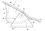
図面の図1〜図5を最初に参照すると、本発明の利点を提供する単純な低コストの回転可能シートクレードル1の第1の好ましい実施形態が示されている。シートクレードル1は望ましくは、従来のブロー成形又は射出成形プラスチックから一体形シェルとして製造される。シートクレードル1は、概して直立した腰部支持背部3であって前記クレードル内に着座した使用者の背中がそれに対接して受け入れられる、腰部支持背部3を含む。シートクレードル1は、腰部支持背部3の反対側の、クレードル1の前方前縁に位置する大腿部支持前部5も含む。使用者の脚は大腿部支持前部5上に載る。シートクレードル1の腰部支持背部3と大腿部支持前部5との間には、着座した使用者の骨盤がその中に受け入れられる深い概してU字形の骨盤支持バケット7が位置する。使用者の下部脊椎は腰部支持背部3の部分4によって係合され、部分4は、骨盤支持バケット7において隣接する後方に突出している部分より前に位置するように、大腿部支持前部5に向けて内向きに及び前方に突出するようにシートクレードル1内に成形される(図5において最も良く示されている)。
First, with reference to FIGS. 1 to 5 of the drawing, a first preferred embodiment of a simple low cost
シートクレードル1は、骨盤支持バケット7から延び(co−extensive)且つ骨盤支持バケット7の上方に垂直に上昇する、一対の対向する側壁8及び10を有する。一対の軸方向で整列された穴(それらのうちの1つ11のみが図2及び図3に示されている)が、シートクレードル1の側壁8及び10を通して形成される。ピボット支持ブッシュ12が、側壁8及び10を通して形成された軸方向で整列された穴11を囲繞し強化するように、各側壁8及び10の外側に固定される。回転可能シートクレードル1の対向する側壁8及び10における穴11及びピボット支持ブッシュ12は、それぞれのピボット(例えば段付きボルト、そのうちの1つ13のみが図1に示されている)をそれらの中に受け入れて、それにより直線状枢動軸14(図2において最も良く示されている)であってその周りでシートクレードル1がそれに加えられる回転力に応じて回転可能な、直線状枢動軸14を確立するように位置付けられる。直線状枢動軸14は、使用者の股関節と実質的に軸方向で整列してシートクレードル1の側壁8と10との間でシートクレードル1を横方向に横断して伸び、その結果、前記クレードルが空の場合、図1及び図3に示すように、クレードル1は前記枢動軸の対向する両側において等しく重みをかけられ、それにより中立位置にバランスされる。
The
図1及び図5において最も良く示されているように、回転可能シートクレードル1はスタンド16に枢動可能に結合される。前記シートクレードルが結合される特定のスタンド16は本発明を限定するものと考えられるべきではない。単なる例として、図1及び図5のスタンド16は、任意の好適な平坦な表面(図5の参照番号20によって図式的に表されている)上に置かれたか又はそれに固定された平坦なベース18を含む。回転可能シートクレードル1がその上に置かれる表面20の形状及び高さ(存在する場合)は、シートクレードルの適用例に応じて選択できる問題である。
As best shown in FIGS. 1 and 5, the
一対の直立したブレース(それらのうちの1つ22のみが図1及び図5に示されている)が、スタンド16の平坦なベース18の各対向する端から垂直上向きに突出する。それぞれの直立したブレース22は、シートクレードル1の側壁8及び10のうちの対応する1つにおける外側ピボット支持ブッシュ12のうちの1つによって囲繞され支持される前述のピボット(例えば段付きボルト13)のうちの1つを保持する。このようにして、回転可能シートクレードル1は、スタンド16によってその平坦なベース18の上方で懸架され、したがって、スタンド16及び前記スタンドがその上に置かれたか又は固定された表面(例えば20)を基準にして(図2の)枢動軸14の周りで前後に回転可能である。
A pair of upright braces, only one of which 22 is shown in FIGS. 1 and 5, project vertically upward from each opposing end of the
回転可能シートクレードル1の重要な詳細として、図1、図3及び図5に示すその中立位置において、支持表面に最も近い骨盤支持バケット7の底部は、大腿部支持前部5の頂部より下方に位置する。より具体的には、上向きに傾斜した移行壁23が、骨盤支持バケット7と大腿部支持前部5との間に連続的且つ互いから(co−extensively)延在する。上向きに傾斜した移行壁23が大腿部支持前部5と接合する移行点は、骨盤支持バケット7の前記底部より上方に、予想される使用者のサイズに応じた距離(図3においてDで示されている)だけ間隔をあけられる。すなわち、シートクレードル1の距離Dは、小さな子供についてはより短くなり、大きな及び/又は長身の人についてはより大きくなる。
As an important detail of the
その上、上向きに傾斜した移行壁23の傾斜は、上向きに傾斜した移行壁23が大腿部支持前部5と接合する前述の移行点を通る水平基準線25に対して45度以下の理想的な角度(図3において24で示されている)を形成する。結果として、クレードル1の大腿部支持前部5は、前記クレードルの前方前縁において、上向きに傾斜した移行壁23から外向きに片持ち状に突出する。したがって、回転可能クレードル1内に着座した使用者の前方移動により、使用者の脚が、対応する回転押力を、片持ち状に突出した大腿部支持前部5に対して時計回り方向に加えることがもたらされ、それにより前記クレードルは、(図2の)枢動軸14の周りで、前記クレードルが枢動可能に結合されたスタンド16に対して回転する。
Moreover, the inclination of the upwardly
図5を特に参照すると、回転可能シートクレードル1内に着座した使用者であって、前記使用者の背中は腰部支持背部3に対接して位置し、前記使用者の脚は片持ち状に突出した大腿部支持前部5上に載り、前記使用者の骨盤は骨盤支持バケット7によって受け入れられた、使用者が示されている。シートクレードル1は、その中立の重量バランスのとれた位置であって、すぐ前で説明したように使用者がその体重を前方に移動させてそれにより大腿部支持前部5に対して前述の押力を加えた場合に、時計回り方向に回転するための準備ができた、中立の重量バランスのとれた位置にある。
With particular reference to FIG. 5, the user is seated in the
所望により存在する姿勢矯正パッド26が、使用者の下背に係合し使用者の脊椎を直立姿勢に駆り立てるために、シートクレードル1の腰部支持背部3から内向きに延在する。これと同じ点に関して、使用者がその体重をシートクレードル1内で大腿部支持前部5に向けて前方に移動させた場合、シートクレードル1の対応する時計回りの回転によって使用者の腰部及び骨盤が上向き及び前方に持ち上げられて、腰部前弯及び骨盤前傾が動的に誘起される。前述の理由で、クレードル1内での使用者の姿勢は、中立の脊椎姿勢に向けて有利に位置付けられる。シートクレードル1の回転により、腰部支持背部3の前方に突出した部分4は使用者の下背内に突き出され、使用者の腰椎に、骨盤から離れる方向の上向きの及び前方への牽引力を提供し、それにより、使用者の着座した骨盤から使用者の体重の荷重が実質的に除かれる。代替として、腰部支持背部3の前方に突出した部分4は平坦にされ除去されてもよく、姿勢矯正パッド26が、使用者の下背内への受け入れのために大腿部支持前部5に向けて突出するようにサイズ決定され位置付けられてもよい。いずれの場合も、本明細書中で開示される回転可能シートクレードル1は、着座した使用者の姿勢及び快適さを向上するように適合される。
A desired
図6及び図7は、先に図1〜図5を参照しながら説明した回転可能シートクレードル1のシーティング適用例の一例を示す。図6及び図7において、シートクレードル1は、互いに並んで整列された複数の同一のシートクレードルと連結されて、競技場、劇場、空港待合室などにおける対応する数の占有者のための快適な屋外用又は屋内用グループシーティング配置を形成している。図6は、着座のための準備ができた中立の重量バランスのとれた位置にある複数のシートクレードル1のそれぞれを示す。図7は、前記シートクレードルが使用されていない場合にコンパクトな収納位置までそれらの枢動軸14(図2)の周りを下向きの時計回り方向に回転されたシートクレードル1を示す。もちろん、占有者の数に応じて、複数の回転可能シートクレードル1のうちの様々なものが、図6及び図7の中立位置及び収納位置まで選択的に回転されてもよい。
6 and 7 show an example of a seating application example of the
図6及び図7に示す例において、各シートクレードル1は、一対のスタンド16−1及び16−2によって地面に枢動可能に結合されており且つ地面の上方で懸架されており、前記一対のスタンド16−1及び16−2は、対応する一対の垂直に直立したブレース22−1及び22−2がクレードルの対向する両側部に位置するように、図1及び図5に示すものと同様に間隔をあけられ対面して整列されて保持されている。平坦なベース18−1及び18−2が、スタンド16−1及び16−2の一対のブレース22−1及び22−2のうちの各1つから水平に延在して地面に固定されている。したがって、シートクレードル1がその上に置かれる図5に示す上昇した表面20は、ここでは省略されていることが理解され得る。所望により存在する一対のアーム28が、一対の直立したブレース22−1及び22−2のうちの各1つに取り付けられており、その上に、前記シートクレードル内に着座した人の腕が載ってもよい。
In the examples shown in FIGS. 6 and 7, each
図面の図8〜図11は、図1〜図5を参照しながら先に説明した回転可能シートクレードル1の別のシーティング適用例を示す。同一の参照番号が、図1〜図5及び図8〜図11に示すシートクレードル1の同一の特徴を示すために使用される。シートクレードル1は、その最も単純な適用例においては、図1、図6、及び図7に示したようなスタンドに枢動可能に結合される必要はない。この場合、シートクレードル1は、例えば図11において30で示されているものなどの従来の椅子の上に単に置かれてもよく、またそこから取り去られてもよい。したがって、シートクレードル1の腰部支持背部3は、椅子30の背部32に隣接して位置し、クレードル1の大腿部支持前部5は、椅子シート34の前部の上に載る。シートクレードル1の骨盤支持バケット7は、椅子背部32の底部及び椅子シート34の後部の両方に対接して位置して示されている。図11の椅子30上に置かれたシートクレードル1内に着座しその体重を移動させている人は有利には、単独の椅子に着席し揺動している間は必ずしも得られない上述の姿勢向上の利益を受ける。
8 to 11 of the drawings show another seating application example of the
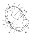
回転可能シートクレードル1は、図1、図6、及び図7に示すスタンド16に枢動可能に結合されるのではなく、図8、図9、及び図10に示すヨーク40に結合された状態で椅子30の上に据えられてもよく、またそこから取り去られてもよい。ヨーク40は好ましくは可撓性プラスチックから製造され、比較的平坦なベース42と、互いに間隔をあけられ対向して整列されて位置しており且つバネ記憶を有している一対の上向きの側壁44とを含む。一対の円筒状カプラー46が、上向きの側壁44から互いに向けて内向きに対面している。ヨーク40は、前記ヨークが図10に示すように椅子30の上に据えられた場合にベース42に支持及び安定性を提供するための、前記ベースから外向きに突出する前側ノーズ48を含む。
The
回転可能シートクレードル1は、最初にヨーク40の可撓性側壁44を外向きに曲げ、次にその円筒状カプラー46を、前記シートクレードルの側壁8及び10から突出しているピボット支持ブッシュ12(図9において最も良く示されている)のうちの各1つと囲繞係合するように位置付けることによって、図8に示すようにヨーク40に枢動可能に且つ取り外し可能に結合される。シートクレードル1とヨーク40との組み合わせは、平坦なベース42及びそこから延在する前側ノーズ48がシート34とじかに接触して位置するように、且つ(図11に示すシーティング配置の場合のように)クレードル1の腰部支持背部3が椅子背部32に隣接して位置するように、椅子30のシート34上に置かれる。使用者がその体重をシートクレードル1内で前後に移動させた場合、前記シートクレードルはその枢動軸(図9において14で示されている)の周りでヨーク40に対して回転して、対応する力を椅子30に伝える。しかし使用者は有利には、単独の椅子からは必ずしも得られない、上述のように回転可能シートクレードル1によって提供される姿勢向上の利益を与えられる。
The
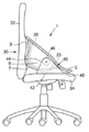
次に図面の図12〜図17を参照すると、本明細書中で開示される回転可能シートクレードル1が、異なる椅子(図13において75で示されており且つ最も良く示されている)に取り付けられた場合の別のシーティング適用例において示されている。この場合、シートクレードル1はヨーク50に結合されており且つ前記ヨークに対して回転可能であり、ヨーク50は椅子75に固定されている。再び、同一の参照番号が、図12〜図17に示すシートクレードル1の同一の特徴を示すために使用されている。次に開示するように、シートクレードル1は、椅子75の通常のシートに取って代わるように、前記椅子の既存のベース72にヨーク50を用いて固定される。
Next, referring to FIGS. 12-17 of the drawings, the
ヨーク50は、その底部に位置するU字形のベース52と、互いに間隔をあけられ対面して整列されて配置された一対の上向きの垂直に延在するストラット54とを含む。アウトストレッチされた(outstretched)クレードル支持アーム56が、ヨーク50の各側において各上向きのストラット54から延びて接続されそこから第1の方向に延在する。アームパッド支持ブレース58が、各ストラット54から延びて接続されそこから第2の方向に延在する。延びて接続されたクレードル支持アーム56及びアームパッド支持ブレース58は、ヨーク50の上向きのストラット54のそれぞれから第1の方向及び第2の方向に延在して、それらの間に約90度の角度を形成する。
The
ヨーク50に結合された回転可能シートクレードル1を有する図13〜図17の組み立てられた椅子構成において、ヨーク50の底部に位置するU字形のベース52は、前記シートクレードルの下で横方向に横断して伸びてプレート77に接続されており、前記プレート77は、椅子75のベース72であって通常の椅子シートが本発明の回転可能シートクレードル1によって取って代わられていなければ前記通常の椅子シートがそこにおいて接続されていたであろうベース72によって支持されている。ベース52から垂直上向きに立つストラット54は、シートクレードル1のそれぞれの側壁8及び10に沿って伸びる。ストラット54から第1の方向に延在するアウトストレッチされたクレードル支持アーム56は、シートクレードル1の後部における腰部支持背部3の背後で互いに延びて且つ連続的に接続される。クレードル1内に着座中に使用者がその腕をもたせ掛けることが可能なアームパッド60は、第2の方向にストラット54から延在するアームパッド支持ブレース58によって支えられる。
In the assembled chair configuration of FIGS. 13-17 with the
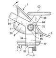
結合穴62(図12において最も良く示されている)が、ヨーク50の対向する両側部を通して、上向きのストラット54とクレードル支持アーム56及びアームパッド支持ブレース58との交差部において形成される。短い静止位置制限キー64が、ストラット54から各結合穴62内に半径方向に突出する。円筒状結合スリーブ66(やはり図12において最も良く示されている)が、ヨーク50の各上向きのストラット54の外側に、結合穴62を囲繞するように取り付けられる(例えば溶接される)。
A coupling hole 62 (best shown in FIG. 12) is formed at the intersection of the
クレードル位置ストッパー(例えばグロメット)68であってその中に形成されたノッチ70を有するクレードル位置ストッパー68が、円筒状結合スリーブ66によって囲繞係合され且つ支持された受け入れのために各結合穴62を通して位置付けられるような寸法に作られる。ストッパー68が結合穴62内に位置しスリーブ66によって保持された状態で、静止位置制限キー64は、前記ストッパー内に形成されたノッチ70内に対応して位置する。クレードル位置ストッパー68は、すぐ後で説明する利点のために、バネ記憶を有するエラストマー材料から形成されてもよい。図14及び図15において最も良く示されているように、ヨーク50の上向きのストラット54によって支えられるクレードル位置ストッパー68は、回転可能シートクレードル1の側壁8及び10の外側上に位置するピボット支持ブッシュ12のうちの各1つに固定され(例えば粘着的に接着されるか又はピン留めされ)、それによりクレードル1はヨーク50に結合される。
A cradle position stopper (eg, grommet) 68 with a
図13は、回転可能シートクレードル1内に着座した使用者を示し、前記シートクレードル1はヨーク50に枢動可能に結合されており、前記ヨーク50は先に説明したように椅子75に固定して接続されている。やはり先に説明したように且つ例として、図13に示す椅子75は、従来のベース72と一組のローラー73とを有する。前記椅子は前述のシートプレート77も有する。しかし、使用者の体重を支持するシートの代わりに、回転可能シートクレードル1とヨーク50との組み合わせが、シートプレート77において椅子70のベース72に接続されている。
FIG. 13 shows a user seated in a
図13〜図15は、中立の(すなわち重量バランスのとれた)位置に位置しているシートクレードル1を示す。この場合、ヨーク50の上向きのストラット54のそれぞれにおける静止位置制限キー64は、クレードル1の対向する側壁8及び10に隣接する各クレードル位置付けストッパー68内に形成されたノッチ70の中央付近に位置している。シートクレードル1とヨーク50とは、クレードル1にそのピボット支持ブッシュ12において接続されたクレードル位置ストッパー68が、ヨーク50のストラット54内に形成された各結合穴62内で回転可能であるように、互いに結合されていることが理解され得る。したがって、シートクレードル1は、ヨーク50及びヨーク50が固定して接続された椅子70を基準にして前後に回転可能である。
13 to 15 show the
この点に関して、図16は、使用者がその体重を後方に移動させた場合にヨーク50を基準にして反時計回り方向に回転されたシートクレードル1を示す。この場合、シートクレードル1の対向する両側部(それらのうちの1つ8のみが可視である)に位置するクレードル位置ストッパー68は、それぞれの静止位置制限キー(それらのうちの1つ64のみが可視である)が、対応するストッパー68の一方の端に、ノッチ70の一方の端において係合するまでクレードル1と共に回転される。同時に、シートクレードル1の腰部支持背部3は、背部3の背後に位置するヨーク50のアウトストレッチされたクレードル支持アーム56に係合する。図16の反時計回り方向でのシートクレードル1の追加の回転は、クレードル位置ストッパー68のうちの各1つによる静止位置制限キー64との、及びクレードル支持アーム56による腰部支持背部3との、同時係合によって阻止される。
In this regard, FIG. 16 shows the
図17は、使用者がその体重を前方に移動させた場合にヨーク50を基準にして時計回り方向に回転されたシートクレードル1を示す。クレードル位置ストッパー68はこの場合、各静止位置制限キー64が、対応するクレードル位置ストッパー68の反対側の端に、ノッチ70の反対側の端において係合するまでシートクレードル1と共に回転され、クレードル1の腰部支持背部3は、ヨーク50のアウトストレッチされたクレードル支持アーム56から離れるように回転する。図17の時計回り方向でのシートクレードル1におけるいかなる追加の回転も、クレードル位置付けストッパー68による静止位置制限キー64との係合によって阻止される。
FIG. 17 shows a
上記に示したように、回転可能シートクレードル1の対向する両側部(例えば8)に取り付けられるクレードル位置ストッパー68は、エラストマー材料から製造されてもよい。この場合、クレードル1が図16及び図17の反時計回り方向又は時計回り方向のいずれかに回転されると、静止位置制限キー64は、回転してそれと係合する各クレードル位置付けストッパー68の一方の端に、対応して押し付けられる。したがって、ストッパー68は最初に圧縮されエネルギーを蓄積する。使用者が前記クレードルを出た場合、ストッパー68が膨張する際にそのバネ記憶特性により、クレードル1はヨーク50を基準にして図13及び図14に示す中立位置に向けて回転するように駆り立てられる。
As shown above, the
本明細書中で開示された回転可能シートクレードルはそのシーティング適用例に関係なく、有利には、使用者の背中への継続的な支持を提供し、同時に、着座した中立の脊椎姿勢と、動的な骨盤前傾と、動的な腰部前弯と、使用者の着座した骨盤から使用者の上体体重の荷重を効果的に除くように使用者の腰椎に加えられる動的な牽引力とを促進し、それにより使用者は、特に前記クレードル内で前傾しているときに最大の快適さを経験することが可能である。 The rotatable seat cradle disclosed herein, regardless of its seating application, advantageously provides continued support to the user's back, while at the same time a seated neutral spinal posture and movement. Pelvic anteversion, dynamic lumbar lordosis, and dynamic traction applied to the user's lumbar spine to effectively remove the load of the user's upper body weight from the user's seated pelvis. Promotes, thereby allowing the user to experience maximum comfort, especially when leaning forward within the cradle.
Claims (6)
使用者が中に着座する一体形で回転可能なシートクレードルであって、前記椅子ベースによって保持されるシートクレードルと、
前記椅子ベースと一体形で回転可能な前記シートクレードルとの間に接続されたヨークであって、一対の直立したストラットを含むヨークと、を備える組み合わせであって、
前記シートクレードルは、
第1の端における背部と、
前記第1の端と反対側の端における前部と、
前記背部と前記前部との間に位置する中間バケットと、
互いに間隔をあけられ対向して位置する一対の側部と、を含み、
前記シートクレードルは、前記背部が実質的に垂直であり、前記中間バケットの底部が実質的に水平であり、前記前部が前記中間バケットの前記底部より上方に位置する、中立位置を有し、
前記シートクレードルは前方向に回転するように構成され、
前記ヨークの前記一対の直立したストラットのそれぞれは、後方向に延在するクレードル支持アームであって、前記シートクレードルの前記背部の背後であって、前記背部から間隔をあけられた位置において互いに接合して、前記シートクレードルが前記クレードル支持アームに向かって後方向へ回転するときに前記シートクレードルの前記背部に係合して、前記シートクレードルのさらなる回転を防止するクレードル支持アームを有し、
前記一対の直立したストラットのそれぞれは、上方向に延在するアームレストであって、上に前記使用者の腕が載せられるアームレストをさらに有し、
前記ヨークは、
前記一対の直立したストラットのそれぞれを通して形成された結合穴と、
前記結合穴内それぞれに位置するクレードルカプラーであって、前記シートクレードルの前記一対の側部の各1つに固定して取り付けられたクレードルカプラーと、を含み、
前記クレードルカプラーは前記結合穴内で回転し、前記シートクレードルは前記ヨークに対して前記前方向及び前記後方向に自由に回転する、組み合わせ。 With a chair base
An integrally rotatable seat cradle on which the user sits, with the seat cradle held by the chair base.
A combination comprising a yoke connected to the chair base and the rotatable seat cradle integrally with a yoke containing a pair of upright struts.
The sheet cradle is
The back at the first end and
The front part at the end opposite to the first end,
An intermediate bucket located between the back and the front,
Includes a pair of sides that are spaced apart from each other and located opposite each other.
The seat cradle has a neutral position in which the back is substantially vertical, the bottom of the intermediate bucket is substantially horizontal, and the front is located above the bottom of the intermediate bucket.
The seat cradle is configured to rotate forward and
Each of the pair of upright struts in the yoke is a rearwardly extending cradle support arm that joins each other behind the back of the seat cradle and at intervals from the back. The seat cradle thus has a cradle support arm that engages with the back of the seat cradle as it rotates backwards towards the cradle support arm to prevent further rotation of the seat cradle.
Each of the pair of upright struts is an upwardly extending armrest, further comprising an armrest on which the user's arm rests.
The yoke is
With the connecting holes formed through each of the pair of upright struts,
A cradle coupler located in each of the coupling holes, including a cradle coupler fixedly attached to each one of the pair of side portions of the sheet cradle.
A combination in which the cradle coupler rotates in the coupling hole and the sheet cradle freely rotates in the anterior and posterior directions with respect to the yoke.
Applications Claiming Priority (3)
| Application Number | Priority Date | Filing Date | Title |
|---|---|---|---|
| US14/747,040 US10314400B2 (en) | 2015-06-23 | 2015-06-23 | Rotatable seat cradle |
| US14/747,040 | 2015-06-23 | ||
| PCT/US2016/038480 WO2016209798A1 (en) | 2015-06-23 | 2016-06-21 | Rotatable seat cradle |
Publications (3)
| Publication Number | Publication Date |
|---|---|
| JP2018519144A JP2018519144A (en) | 2018-07-19 |
| JP2018519144A5 JP2018519144A5 (en) | 2019-07-11 |
| JP6888236B2 true JP6888236B2 (en) | 2021-06-16 |
Family
ID=57585599
Family Applications (1)
| Application Number | Title | Priority Date | Filing Date |
|---|---|---|---|
| JP2018519682A Active JP6888236B2 (en) | 2015-06-23 | 2016-06-21 | Rotatable seat cradle |
Country Status (6)
| Country | Link |
|---|---|
| US (2) | US10314400B2 (en) |
| EP (1) | EP3310211A4 (en) |
| JP (1) | JP6888236B2 (en) |
| KR (1) | KR20180043248A (en) |
| AU (2) | AU2016284054B2 (en) |
| WO (1) | WO2016209798A1 (en) |
Families Citing this family (8)
| Publication number | Priority date | Publication date | Assignee | Title |
|---|---|---|---|---|
| US20160374468A1 (en) * | 2015-06-29 | 2016-12-29 | Ipic-Gold Class Entertainment, Llc | Theater Seating |
| IT201700058665A1 (en) * | 2017-05-30 | 2018-11-30 | Maddalena Maria Martera | OSCILLATING ARMCHAIR WITH ASSIGNED POSTURE |
| CN114007465A (en) * | 2019-04-16 | 2022-02-01 | 赫尔曼米勒有限公司 | Actively engaged chair for user |
| WO2020247435A1 (en) | 2019-06-05 | 2020-12-10 | Davis Furniture Industries, Inc. | Improved tilting chair |
| KR102278981B1 (en) * | 2019-12-24 | 2021-07-16 | 한화큐셀앤드첨단소재 주식회사 | An outdoor chair made of glass fiber mat reinforced thermoplastics in which a seat is turned itself over |
| US11154136B2 (en) * | 2020-03-12 | 2021-10-26 | Davis Furniture Industries, Inc. | Double shell seat |
| US11825949B2 (en) | 2021-05-04 | 2023-11-28 | Michael David Collier | Ergonomic motion chair |
| US11229291B1 (en) | 2021-05-04 | 2022-01-25 | Michael David Collier | Ergonomic motion chair |
Family Cites Families (43)
| Publication number | Priority date | Publication date | Assignee | Title |
|---|---|---|---|---|
| US1688587A (en) * | 1926-07-08 | 1928-10-23 | Frans J Liljedahl | Rocking-chair |
| US2779389A (en) * | 1953-09-17 | 1957-01-29 | Benjimen H Pearl | Convertible high chair swing |
| US3142514A (en) * | 1962-03-05 | 1964-07-28 | Jonathan J Ginat | Chair |
| US3711152A (en) * | 1971-08-11 | 1973-01-16 | Casey Sirpak Inc | Health chair |
| US4500137A (en) | 1982-01-21 | 1985-02-19 | Morehouse Laurence E | Physiological chair |
| US4529247A (en) * | 1982-04-15 | 1985-07-16 | Herman Miller, Inc. | One-piece shell chair |
| US4545613A (en) * | 1983-03-18 | 1985-10-08 | Cosco, Inc. | Car seat carrier |
| DE3325372A1 (en) | 1983-07-14 | 1985-01-24 | Basf Ag, 6700 Ludwigshafen | METHOD FOR THE PRODUCTION OF PURE ADIPINO ACID MONOESTERS |
| US5050931A (en) * | 1986-04-10 | 1991-09-24 | Steelcase Inc. | Controlled deflection front lip for seating |
| US4852945A (en) | 1986-04-24 | 1989-08-01 | Rowles John W | Comprehensive contour chair apparatus |
| JPS6357958A (en) | 1986-08-26 | 1988-03-12 | Mazda Motor Corp | Stepless speed changer with belt |
| US5368359A (en) * | 1988-08-31 | 1994-11-29 | Eakin; Byron C. | Acoustical chair with sound enhancing hood |
| US5024485A (en) * | 1990-07-05 | 1991-06-18 | Berg Joseph A | Front and back adjustable rocking seat support arrangement for seat having relatively adjustable sections |
| US5318346A (en) * | 1991-05-30 | 1994-06-07 | Steelcase Inc. | Chair with zero front rise control |
| US5383709A (en) * | 1992-12-03 | 1995-01-24 | Zoetech, Inc. | Orthopedic chair with forwardly and rearwardly inclined positions |
| DE9303674U1 (en) | 1993-03-12 | 1993-05-19 | Kraus, Berthold, 6600 Saarbruecken, De | |
| US5516134A (en) * | 1994-09-20 | 1996-05-14 | Perfect Season, Inc. | Seat for a wheeled vehicle |
| US5509719A (en) * | 1994-11-04 | 1996-04-23 | Cosco, Inc. | Multi-position chair |
| US6050642A (en) * | 1996-05-13 | 2000-04-18 | Erb; Scott C. | Multi-direction reclining and stretching chair |
| US5738409A (en) * | 1997-01-08 | 1998-04-14 | Bursik; Thomas A. | Rocking chair construction |
| US5984409A (en) * | 1998-04-10 | 1999-11-16 | Somatron Corporation | Reclining chair assembly |
| US6168233B1 (en) * | 2000-03-15 | 2001-01-02 | Isidoro Natalio Markus | Reclinable seating using a torsion bar |
| US6325455B1 (en) * | 2000-05-11 | 2001-12-04 | Homedics, Inc. | Reclining chair |
| US6394547B1 (en) | 2000-06-23 | 2002-05-28 | David J. Vik | Ergonomic chair |
| US7081052B2 (en) * | 2003-03-26 | 2006-07-25 | Graco Children's Products Inc. | Foldable swing having rotatable handles |
| US6969429B2 (en) * | 2003-07-08 | 2005-11-29 | Muhlhan Surface Protection International Gmbh | Method for removing blast media and colored residues comprising an aqueous slurry suspension |
| US6974188B2 (en) * | 2003-08-13 | 2005-12-13 | Cosco Management, Inc. | Chair with pivotable chair back |
| DE102004002231B3 (en) * | 2004-01-07 | 2005-04-14 | Gunter Kubatsch | Seat has base frame with central column terminating in a domed bearing and swashplate |
| US7607738B2 (en) | 2005-09-15 | 2009-10-27 | Matthew Wayne Gregory | Contoured seat and method |
| JP4931421B2 (en) | 2006-01-10 | 2012-05-16 | 株式会社デルタツーリング | Seat structure |
| US20070222266A1 (en) * | 2006-03-21 | 2007-09-27 | Ditto Sales, Inc. | Nestable and stackable chair |
| ITVR20060060A1 (en) * | 2006-03-30 | 2007-09-30 | Inglesina Baby Spa | STRUCTURE OF CHAIRS |
| WO2007129906A1 (en) * | 2006-05-10 | 2007-11-15 | Proesch Jon Olav | Device for furniture |
| US8251382B2 (en) * | 2007-06-06 | 2012-08-28 | Wonderland Nurserygoods Co., Ltd. | Stroller and seat assembly mechanism for a stroller |
| US7850238B2 (en) * | 2007-07-16 | 2010-12-14 | Erb Scott C | Dynamic furniture |
| US7677663B1 (en) * | 2007-09-27 | 2010-03-16 | Anthony Charles, legal representative | Safety seat assembly |
| US10034548B2 (en) * | 2009-01-23 | 2018-07-31 | Backjoy Orthotics, Llc | Apparatus and system for dynamically correcting posture |
| EP2381817B1 (en) | 2009-01-23 | 2013-07-10 | Backjoy Orthotics, LLC | Method and apparatus for dynamically correcting posture |
| US20100269352A1 (en) * | 2009-04-28 | 2010-10-28 | Progressive International Corporation | Y peeler |
| CN102727001B (en) * | 2011-03-31 | 2015-04-29 | 王鲲 | High chair |
| US8926017B2 (en) * | 2012-09-06 | 2015-01-06 | James E. Grove | Chair with integral pivoting lumbar and seat cushion portions |
| GB2511031A (en) * | 2012-12-22 | 2014-08-27 | Roger Hollest | A rocking chair |
| JP2014237414A (en) * | 2013-06-10 | 2014-12-18 | トヨタ紡織株式会社 | Vehicular seat |
-
2015
- 2015-06-23 US US14/747,040 patent/US10314400B2/en active Active
-
2016
- 2016-06-21 KR KR1020187001906A patent/KR20180043248A/en not_active Application Discontinuation
- 2016-06-21 EP EP16815129.8A patent/EP3310211A4/en not_active Withdrawn
- 2016-06-21 AU AU2016284054A patent/AU2016284054B2/en active Active
- 2016-06-21 JP JP2018519682A patent/JP6888236B2/en active Active
- 2016-06-21 WO PCT/US2016/038480 patent/WO2016209798A1/en unknown
-
2019
- 2019-05-06 US US16/403,954 patent/US11089874B2/en active Active
-
2021
- 2021-06-22 AU AU2021204204A patent/AU2021204204A1/en not_active Abandoned
Also Published As
| Publication number | Publication date |
|---|---|
| WO2016209798A1 (en) | 2016-12-29 |
| EP3310211A4 (en) | 2021-07-14 |
| US11089874B2 (en) | 2021-08-17 |
| JP2018519144A (en) | 2018-07-19 |
| AU2016284054A1 (en) | 2018-02-15 |
| US10314400B2 (en) | 2019-06-11 |
| AU2016284054B2 (en) | 2021-04-01 |
| US20160374471A1 (en) | 2016-12-29 |
| KR20180043248A (en) | 2018-04-27 |
| AU2021204204A1 (en) | 2021-07-15 |
| US20190254430A1 (en) | 2019-08-22 |
| EP3310211A1 (en) | 2018-04-25 |
Similar Documents
| Publication | Publication Date | Title |
|---|---|---|
| JP6888236B2 (en) | Rotatable seat cradle | |
| US4555139A (en) | Patient's defined-motion chair | |
| JP5442792B2 (en) | Lumbar support cushion | |
| US7243935B2 (en) | Wheelchair having a pivot provision adjacent the knee of a user | |
| EP2156766B1 (en) | Chair (variants) | |
| US20120175928A1 (en) | Seating assembly with pivoting motion | |
| US6655731B2 (en) | Therapeutic chair | |
| JP2020108780A (en) | Adjustable ergonomic chair | |
| WO2011087232A2 (en) | Supporting device of posture correction chair | |
| US9867472B2 (en) | Active dynamic chair | |
| WO2017193211A1 (en) | Lounge chair with ergonomic features | |
| KR102250315B1 (en) | move chair | |
| US673100A (en) | Invalid's walking-chair. | |
| KR101071058B1 (en) | Folding type supporter apparatus of chair | |
| US5181764A (en) | Chair and seat apparatus, and methods of constructing and utilizing same | |
| ES2672935T3 (en) | Hospital armchair equipped with a system to help patients to sit and get up | |
| JP7440901B2 (en) | Training equipment, training methods, and training chairs | |
| KR102290271B1 (en) | Multi-function Chair | |
| US6773066B2 (en) | Control for a seat, and a seat incorporating it | |
| KR102189736B1 (en) | the chair for the body portion attaching type task in which the breastplate is included | |
| JP2011024689A (en) | Standing-up support chair | |
| KR200423526Y1 (en) | Wheel chair for physically handcapped person | |
| KR200371218Y1 (en) | Tiltable-chair for the upper body | |
| KR200222794Y1 (en) | A invertable-chair for the upper body. | |
| TWM535506U (en) | Lumbar-supporting cushion |
Legal Events
| Date | Code | Title | Description |
|---|---|---|---|
| A521 | Request for written amendment filed |
Free format text: JAPANESE INTERMEDIATE CODE: A523 Effective date: 20180131 |
|
| A711 | Notification of change in applicant |
Free format text: JAPANESE INTERMEDIATE CODE: A711 Effective date: 20180525 |
|
| A521 | Request for written amendment filed |
Free format text: JAPANESE INTERMEDIATE CODE: A821 Effective date: 20180525 |
|
| A521 | Request for written amendment filed |
Free format text: JAPANESE INTERMEDIATE CODE: A523 Effective date: 20190606 |
|
| A621 | Written request for application examination |
Free format text: JAPANESE INTERMEDIATE CODE: A621 Effective date: 20190606 |
|
| A977 | Report on retrieval |
Free format text: JAPANESE INTERMEDIATE CODE: A971007 Effective date: 20200730 |
|
| A131 | Notification of reasons for refusal |
Free format text: JAPANESE INTERMEDIATE CODE: A131 Effective date: 20200811 |
|
| A521 | Request for written amendment filed |
Free format text: JAPANESE INTERMEDIATE CODE: A523 Effective date: 20201110 |
|
| TRDD | Decision of grant or rejection written | ||
| A01 | Written decision to grant a patent or to grant a registration (utility model) |
Free format text: JAPANESE INTERMEDIATE CODE: A01 Effective date: 20210420 |
|
| A61 | First payment of annual fees (during grant procedure) |
Free format text: JAPANESE INTERMEDIATE CODE: A61 Effective date: 20210430 |
|
| R150 | Certificate of patent or registration of utility model |
Ref document number: 6888236 Country of ref document: JP Free format text: JAPANESE INTERMEDIATE CODE: R150 |
|
| S531 | Written request for registration of change of domicile |
Free format text: JAPANESE INTERMEDIATE CODE: R313531 |
|
| S533 | Written request for registration of change of name |
Free format text: JAPANESE INTERMEDIATE CODE: R313533 |
|
| R350 | Written notification of registration of transfer |
Free format text: JAPANESE INTERMEDIATE CODE: R350 |